1
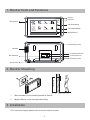
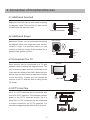
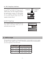
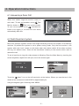
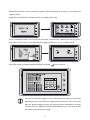
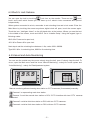
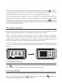
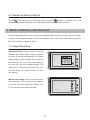
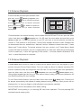
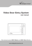
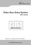
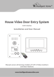
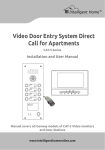
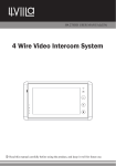
Cronus Video Door Phone
2-wire Series
Installation and User Manual
Main Menu
Manual
Monitor
1
Monitor
3
Memory
Playback
4
Intelligent Home
2
Album
Intercom
User Setup
Multimedia
Close
02/12/2010 Thu.10:41AM
Image Recording Version
1
2
3
4
Monitor ...
Manual Monitor
Intercom
User Setup
Close
i About
No Memory Version
Digital Touch Screen 7 inch Monitor
www.intelligenthomeonline.com
PRECAUTIONS
●● Read this manual through before using the product.
●● Slots or openings in the back of the monitor, are provided for ventilation
and to ensure reliable operation of the video monitor or equipment and
to protect if from overheating. These openings must not be blocked or
covered. The monitor should never be placed near or over a radiator or
heat register and should not be placed in a built-in installation such as a
bookcase unless proper ventilation is provided.
●● All parts should be protected from violence vibration. Prevent impacts,
knocking and dropping.
●● Clean the LCD monitor with Plastic Protection cleaner only.
●● Image distortion may occur if the video door phone is mounted too close
to magnetic field e. g. Microwaves, TV, computer etc.
●● Please keep away the video door monitor from wet, high temperature,
dust, and caustic and oxidation gas in order to avoid any unpredictable
damage.
●● Do NOT open the device in any condition, call the administrator for help
if there is any problem or mulfunction happens.
CONTENT
1. Monitor Parts and Functions - - - - - - - - - - - - - - - - - - - - - - - - - - - 1
2. Monitor Mounting- - - - - - - - - - - - - - - - - - - - - - - - - - - - - - - - - - - - 1
3. Installation- - - - - - - - - - - - - - - - - - - - - - - - - - - - - - - - - - - - - - - - - - 1
4. Connection of Peripheral Devices - - - - - - - - - - - - - - - - - - - - - - - 2
5. Cable usage - - - - - - - - - - - - - - - - - - - - - - - - - - - - - - - - - - - - - - - - - 3
6. Operation Instructions - - - - - - - - - - - - - - - - - - - - - - - - - - - - - - - - 4
7. Built-in Memory and SD Card- - - - - - - - - - - - - - - - - - - - - - - - - - - 8
8. Specifications- - - - - - - - - - - - - - - - - - - - - - - - - - - - - - - - - - - - - - - 10
1. Monitor Parts and Functions
Screen
Indicator
Microphone
Manual
Monitor
Memory
Playback
Intercom
Monitor
User Setup
Album
Multimedia
Close
02/12/2010 Thu.10:41AM
Intelligent Home
UNLOCK Button
TALK/MON Button
MENU Button
Mounting Hook
Speaker
Peripheral Devices
Connection Port
BT1
BT2
EH
GND
VD
DIP Switches
DIPS
ON
123456
L1
L2
Mounting Hook
SD card slot
145~160 cm
2. Monitor Mounting
1. Use the screws to fix the mounting bracket on the wall;
2. Hang the Monitor on the mounting bracket firmly.
3. Installation
For connection diagram please refer to the door station manual.
-1-
4. Connection of Peripheral Devices
4.1 Additional Doorbell
Additional Door Bell can be connected according
SW+
SWEXT-RING
GND
VIDEO
the diagram below. There will be no video on the
monitor when this door bell used.
Door bell call button
4.2 Additional Ringer
Additional Ringer can be connected according
External Ringer
the diagram below. One ringer per video monitor.
Locate a ringer in a position where you are
unlikely to hear the ringing of the monitors like a
garage, shed, garden or porch.
-
SW+
SWEXT-RING
GND
VIDEO
+
12Vdc 300mA
4.3 Connection To a TV
Each monitor can be connected to a TV with
Television
antenna cable according the diagram below. The
core of antenna cable must be connected to the
Video and the shield to the GND. When the door
station rings you don’t have to walk to the monitor
to see the visitor. Instead you can change AV
channel on the TV and see who is calling on the
SW+
SWEXT-RING
GND
VIDEO
video cable
TV screen.
4.4 CCTV Interface
AC
Up to 2 x CCTV cameras can be connected with
one DCU CCTV Interface. This interface provides
power to the CCTV cameras as well. Up to a
three DCU CCTV Interfaces can be connected
to support maximum six CCTV cameras. For
connection diagram please refer to DCU manual.
-2-
ON
123456
DCU
ON
1234
4.5 TPC Telephone Interface
TPC Telephone Interface Allows you to callforward from a door station to a mobile phone or
to telephone
landline phone. One TPC Telephone Interface
to telephone
network
per house system required. For Flats system
one TPC Telephone Interface per flat required.
For connection diagram please refer to TPC
TPC
telephone Interface manual.
4.6 IPC IP Interface
IPC IP Interface Allows you to connect your door
entry system to the Internet. Allows you to see
and answer the door via web.
5. Cable usage
The best cable for this system is 2-wire twisted pair cable; 2-wire stranded core such as power
flex cable or certain speaker cables. CAT5 or CAT6 can be used as well (not recommended) if
all cores are paired up in two sets of cores.
Cable type
Max. distance(meters)
RVV 2 * 1.5 mm2
300 (Non-shielded, Twisted)
RVV 2 * 1.0 mm2
200 (Non-shielded, Twisted)
RVV 2 * 0.75 mm2
150 (Non-shielded, Twisted)
-3-
6. Operation Instructions
6.1 Answering a Door Call
When door station rings the monitor comes on
with video. To start conversation, touch
Monitor button or
Talk/
1:1
Talk icon on the screen.
To end conversation touch
Talk/Monitor
button once again or, monitor will shut down
automatically after 90s.
Home
6.2 Multi Monitors System
Most multi monitors systems contain one Image Recording monitor and number of No Memory
monitors. By default the system is set to power saving mode. Only the first monitor in the
system, with code “zero” comes on with video when door station called. All the other monitors
will ring, but without video. Video will be transferred instantly to the monitor which used to
answer the call.
To set all monitors to ring with video please do following: Enter the Main Menu by touching the
screen anywhere; digital clock will open, touch the screen again.
22/04/2011
11 : 44
Fri.
AM
i
Touch the “
About” icon on the left hand side, at the bottom. Where you see the text in the
middle of the screen,touch and HOLD for approximately 2s
Using the keypad, type in following code: 8006#.
Input Code Number:[- - - -]
1
4
7
i
Exit
Exit
-4-
*
2
5
8
0
3
6
9
#
Home
Repeat this process on ALL monitors in system. After completing all monitors, your system will
ring with video.
Image Recording Monitor settings can be accessed similar way.
Intelligent Home
Touch “Intelligent Home” icon on the left hand side, at the bottom. Where you see the text in
the middle of the screen, touch and HOLD for approximately 2s. Go to “Installer Setup”.
Using the keypad, program desired settings and press
icon to save it.
You may increase the power on the combined power supply if needed by
adjusting power on the PS5 to a higher power (maximum 32V). If you feel
that one power supply provides not enough power (depends on number
of video monitors, additional devices and distances) you may need to add
a second combined power supply.
-5-
6.3 Electric Lock Release
You can open the lock by touching
Lock icon on the monitor. There are two
icons
Lock1 and Lock2 which means you can have up to 2 electric locks connected and opened
independently.
When system connected to a lock, remember to set unlocking time and a lock mode. Enter the
Main Menu by touching the screen anywhere; digital clock will open, touch the screen again.
Touch the icon “Intelligent Home” on the left hand side, at the bottom. Where you see the text
in the middle of the screen, touch and HOLD. Go to ‘Installer Setup’. Using the keypad, type in
following codes:
8010 # for Power-on-to open lock;
8011 # for Power-off-to open lock.
Next step to set the unlocking time between 1~9s, codes 8021~8029#.
Type 8021 # for 1s unlocking time, 8029 for 9s unlocking time.
6.4 Manual and Auto Monitoring
You can see the outside any time even nobody rings the bell, even if nobody rings the bell. To
do so, open the Main menu and find icons “Manual Monitoring”- mainly for house system and
“Auto Monitoring” - mainly for Flats/Apartment system.
Manual monitoring allows choosing door station or CCTV cameras (if connected) manually.
Camera 1 is representing main door station.
Camera 2 could be second door station or DCU CCTV Interface with two CCTV cameras
connected.
Camera 3 could be third door station or DCU with two CCTV cameras.
Camera 4 could be forth door station or DCU with two CCTV cameras.
-6-
When CCTV monitored manually it will work the following way: for example
Camera 2
is connected to a DCU with two CCTV cameras, so it will show video from CCTV cameras
switching between two of them every 20 sec for as long as monitoring time was set.
Auto monitoring will show in sequence all door stations/CCTV cameras connected with time
interval was set by additional software. To set the monitoring time for “Manual Monitoring” please
do following: go to Main menu and then to Manual Monitoring. You will see the
Monitoring
Time. Using the digital keypad set desired monitoring time following by #. Monitoring time could
be set for a maximum 99min 99s.
6.5 Intercom Function
There are two types of Intercom between monitors. Each one of them depends on system
settings. Please decide before you do the programming, which way you prefer.
TYPE 1. Intercom by “Name list” allows you to call to a specific monitor in the system.
Programming should be done by DIP switches. Name list could be created with additional
software which is a little bit complicated. Monitor numbers could be used instead of names. You
will have to memorise or make a note what number represents which room.
TYPE 2. Intercom “Inner Call” when you started a call from one of the monitors, then all
monitors in the system will ring. Programming should be done via menu (Master, Slave
monitors)
Home
02/12/2010 Thu.10:41AM
6.6 Ring Tone Settings
Touch
User setup icon on the main menu and you will see different ring tones for door
station, Intercom, Day and Night rings which can be selected and saved.
6.7 Screen Settings
Screen settings, such as brightness, colour, scene and talk volume are accessible when the
monitor is in monitoring state. Touch
Talk/Monitor button and then the
Change parameters as desired and save your settings.
-7-
Adjust icon.
6.7 Restore to Factory Default
Touch
User setup icon on the main menu and then
Restore to Default icon. Clock
settings and pictures stored will not be affected by restoring to the factory default.
7. Built-in Memory and SD Card
Cronus Image Recording version has been equipped with an internal memory (about 120 Mb,
enough to store approximately 800 pictures) together with a SD card reader which supports
Micro SD card for a maximum 16 Gb.
7.1 Image Recording
Auto Recording: When someone rings the
doorbell, the monitor takes a picture (default)
or series of pictures automatically. To change
3
1
default setting, open the Main menu and find
Multi Media icon. Then touch the Memory
0
icon and you will see a digital keypad. The
Cancel
options are: 1/4/8 pictures taken every 1.5s.
All other digits are invalid. Press # to save
your setting.
Manual Recording: can be initiated at any
time manually. To do so touch the Capture
DS1
00:03
icon while monitoring the door station or a
Talking
1:1
Standard
Screen
Unlock
CCTV camera and it will be recorded.
Talk
Recording...
Capture
Home
-8-
7.2 Pictures Playback
To see recorded pictures open the Main menu
and then touch
Touch
touch
and
Delete icon to delete selected
pictures or touch
Touch
pictures.
Memory Playback icon.
icon to scroll the pictures,
to delete all pictures.
Zoom icon to zoom selected
Home
Pictures stored in the internal memory can be copied onto the SD card. To do so, open the “Main
Multimedia icon. Put SD card into card reader slot and then touch
menu” and then touch
Memory to SD icon. To view the pictures on your PC you have to convert pictures recorded by
monitor in TVS format to a JPG format. T-views Photo software should be used. Software can
be downloaded from our website from “Manuals” section. Software contains two tools, T-views
Memo and T-views Album. To transfer pictures from your monitor, use T-views Memo. Make
sure the SD card is inserted in your PC or laptop before you start work. Select the pictures (press
Ctrl+A to select all) ->>click the right key of the mouse - >>choose transfer selected to JPG
item - >>save the pictures on computer.
7.2 Pictures Playback
T-views Album tool should be used to create picture albums which can be played on your
monitor using the Picture Frame feature. To do so create an album in software importing JPG
pictures (maximum 800) and copy them onto SD card. To set Picture Frame time parameters
Multimedia icon and then
Album Options icon.
open the Main menu and then touch
Using digital keypad type the time you want picture frame to play your pictures (maximum 99
min 99s) followed by # to save settings.
Album icon. Pictures will
To use Picture frame feature, open the Main menu then touch
be played automatically with speed of loading determined by pixel size. Each picture will be
displayed for 5 s. Use your finger to slide left/right to view pictures manually.
Picture Frame will be interrupted by door station calling.
IMPORTANT: avoid putting in, or removing SD card under operation. This may damage SD
card and internal memory chip.
-98-
8. Specifications
●● Power consumption: Standby 15mA; Working status 400mA
●● Monitor screen: 7 Inch TFT-LCD Touch screen
●● Display Resolutions: 800 x 480pixels
●● Built-in Memory: 120 MB >800 pcs
●● Picture Memo: >30000pcs(2G SD card)
●● Monitor Dimension: H125 × W225 × D23 mm
-10-
Note:
WARRANTY CARD
NB Please keep this document safe, as it is proof of your Warranty
Your Video door system comes with a one year Manufacturers Warranty. When
used normally, the following services are offered:
1. Replacement for malfunctioning parts in first three months
2. Repair free of charge for malfunctioning parts in first year
The following actions will void the Warranty:
1. Damage to the device during installation
2. Damage to the device through misuse
3. Opening and/or disassembling the device
4. Attempting to force the device to perform functions for which it is not intended
5. Attaching the device to power supplies other than thoserecommended by the
manufacturer
Distributor for Warranty purposes:
Intelligent Home Online Ltd
34a High Street
Hornsey
London
N87NX
+44 (0)20 83482040
www.intelligenthomeonline.com
Product:_____________________________________________
Purchaser Name: ______________________________________
Invoice N: ____________________________________________
Purchase Date_________________________________________
Cronus 2-wire V1 2012-08-11
The design and specifications can be changed without notice to the user.
Right to interpret and copyright of this manual are preserved.
www.intelligenthomeonline.com