1
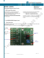
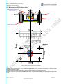
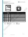
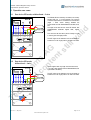
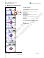
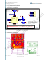
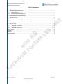
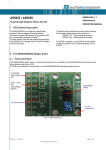
austriamicrosystems AG
is now
ams AG
The technical content of this austriamicrosystems application note is still valid.
Contact information:
Headquarters:
ams AG
Tobelbaderstrasse 30
8141 Unterpremstaetten, Austria
Tel: +43 (0) 3136 500 0
e-Mail: [email protected]
Please visit our website at www.ams.com
AS5040 8-bit Programmable Magnetic Rotary Encoder
AS5050-AB-v1.1
Adapterboard
AS5050 / AS5055
Programmable Magnetic Rotary Encoder
OPERATION MANUAL
1 VDD General Description
The AS5055 is available in a small QFN 16-pin 4x4x0.85mm
package and specified over an operating temperature of -20
to +85°C.
am
lc s
on A
te G
nt
st
il
2 The AS5050/AS5055 Adapter board
2.1
al
id
The absolute angle measurement provides instant indication
of the magnet’s angular position with a resolution of:
AS5050: 0.35° = 1024 positions per revolution
AS5055: 0.09° = 4096 positions per revolution
lv
The AS5050/AS5055 is is a single-chip magnetic rotary
encoder IC with low voltage and low power features.
It includes 4 integrated Hall elements, a high resolution ADC
and a smart power management controller.
The angle position, alarm bits and magnetic field information
are transmitted over a standard 3-wire or 4-wire SPI interface
to the host processor.
Board description
The AS5050/AS5055 adapter board is a simple circuit allowing test and evaluation of the AS5050/AS5055 rotary encoder quickly
without building a test fixture or PCB.
The PCB can be attached to a microcontroller or to the AS5050/AS5055-DB Demoboard as external device.
J1 connector
Power supply
SPI
3 wire – 4 wire
SPI
communication
selection
4 x 2.6mm
mounting holes
Figure 1: AS5050 Adapterboard
Te
ch
ni
INT/ output EN input
ca
AS5050/AS5055
encoder
Revision 1.1, May 2010
Page 1 of 10
www.austriamicrosystems.com
AS5050 / AS5055 Magnetic Rotary Encoder
Adapterboard Operation Manual
2.2
Mounting the AS5050 adapter board
Rotating shaft and magnet holder
Bearing
Not ferromagnetic (plastic, brass, copper,
stainless steel, aluminum…)
Casing
M2~M2.5 Screw + nut
Figure 2: AS5050 adapter board mounting and dimension
Te
ch
ni
ca
am
lc s
on A
te G
nt
st
il
lv
AS5050-AB PCB
al
id
Spacer
A diametric magnet must be placed over on under the AS5050/AS5055 encoder, and should be centered on the middle of the
package with a tolerance of 0.5mm.
The airgap between the magnet and the encoder casing should be maintained in the range 0.5mm~2mm.
The magnet holder must not be ferromagnetic. Materials as brass, copper, aluminum, stainless steel are the best choices to make
this part.
Revision 1.1, May 2010
Page 2 of 10
www.austriamicrosystems.com
AS5050 / AS5055 Magnetic Rotary Encoder
Adapterboard Operation Manual
3 AS5050/AS5055 and adapter board pinout
VDDp
VDD
INT/
GND
MOSI
SCK
MISO
SS/
J1
JP2
al
id
3W – 4W
JP1
Int-EN/
AS505x
Pin#
Pin#
Symbol
Type
Description
Board
J1 - 1
7
VDDp
S
Peripheral power supply, 1.8V ~ VDD
J1 - 2
9
VDD
S
Analog and digital power supply, 3.0 ~ 3.6V
J1 - 3
10
GND
S
Supply ground
J1 - 4
11
INT/
DIO
J1 - 5
15
MOSI
DI
SPI bus data input
J1 - 6
16
MISO
DO
SPI bus data output
J1 - 7
8
SCK
DI_PD
SPI Clock Schmitt trigger
J1 - 8
8
SS/
DI_PD
SPI Slave Select, active LOW
JP1
7
Wire_Mode
S
JP2
1
INT_EN/
DO_OD
am
lc s
on A
te G
nt
st
il
Board
AS5050/
AS5055
lv
Figure 3: AS5050/AS5055 adapter board connectors and encoder pinout
Interrupt output. Active LOW, when conversion is finished
3 wire mode or 4 wire mode SPI communication
Close: enable INT/ output
Pin 1 is the AS505x En_INT/ input. Can be used for interrupt daisy chain (see chapter 4.3)
Table 1: Pin description
ca
digital output open drain
digital output
digital input pull-down
digital input pull-up
S
DI
DO_T
ST
supply pin
digital input
digital output / tri-state
Schmitt-Trigger input
Te
ch
ni
Pin types: DO_OD
DO
DI_PD
DI_PU
Revision 1.1, May 2010
Page 3 of 10
www.austriamicrosystems.com
AS5050 / AS5055 Magnetic Rotary Encoder
Adapterboard Operation Manual
4 Operation use cases
4.1
One device SPI mode, unidirectional – 3 wire
al
id
The AS5050-AB can be directly connected to an industry
standard SPI port of a microcontroller. The minimum
connection requirement for unidirectional communication
(angle + alarm values reading) between the
microcontroller and the AS5050/AS5055 are MISO, SCK,
SS/.
The angle will be read at each 16-bit SPI transfer. See
AS5050/AS5055 datasheet register table, register
3FFFh.
This value must be read with a period of 600µs or more
in order to get a new angle position.
4.2
am
lc s
on A
te G
nt
st
il
lv
The INT/ signal can be attached o the microcontroller to
indicate that a new angle position has been calculated.
One device SPI mode,
bidirectional – 4 wire
If other registers than only angle value have to be read,
or in order to write registers into the AS5050/AS5055, the
signal MOSI is necessary.
Te
ch
ni
ca
The INT/ signal can be attached o the microcontroller to
indicate that a new angle position has been calculated.
Revision 1.1, May 2010
Page 4 of 10
www.austriamicrosystems.com
AS5050 / AS5055 Magnetic Rotary Encoder
Adapterboard Operation Manual
4.3
Multi devices SPI Daisy chain mode
The AS5050/AS5055 can be daisy chained, using 4 wires
only for SPI communication.
lv
al
id
In this configuration with n x encoders, the sequence will
be processed as follow:
- MCU sets SS/ = 0
- MCU shifts n x 16-bit (e.g. READ command FFFFh)
through the chain
- MCU sets SS/=1
At that point all the n x encoders have received the
READ command FFFFh.
- MCU sets SS/=0
- MCU shifts n x 16-bit (e.g. NOP command 0000h)
- MCU sets SS/=1
At that point the n x 16-bit received on MISO are the n x
angle values.
Te
ch
ni
ca
am
lc s
on A
te G
nt
st
il
If an interrupt is needed, the signal INT/ can be daisy
chained as shown on the diagram on the left. The final
INT/ signal connected to the MCU will go LOW only if all
the n x encoders INT/ = 0. The n x 16-bit angle readout
can be performed here.
Revision 1.1, May 2010
Page 5 of 10
www.austriamicrosystems.com
AS5050 / AS5055 Magnetic Rotary Encoder
Adapterboard Operation Manual
5 Firmware coding
The following source code fits the 4-Wire application (chapter 4.2).
The function void spiReadData() reads/writes 3 values from
- Send command READ AGC / Receive value unknown
- Send command READ Angle / Receive value AGC
- Send command NOP (no operation) / Receive value ANGLE
the AS5050/AS5055
The function static
stream.
al
id
If a READ ANGLE only is necessary in a loop, the procedure can be reduced to one line:
- Send command READ Angle / Receive value Angle (T-1)
u8 spiCalcEvenParity(ushort value) is optional, it calculates the parity bit of the 16-bit SPI
am
lc s
on A
te G
nt
st
il
lv
/*!
*****************************************************************************
* Reads out chip data via SPI interface
*
* This function is used to read out cordic value from chips supporting SPI
* interface.
*****************************************************************************
*/
#define SPI_CMD_READ 0x8000
/*!< flag indicating read attempt when using SPI interface */
#define SPI_REG_DATA 0x7ffe
/*!< data register when using SPI */
#define SPI_REG_AGC
0x7ff0
/*!< agc register when using SPI */
#define SPI_REG_CLRERR 0x6700
/*!< clear error register when using SPI */
void spiReadData()
{
u16 dat;
ushort angle, agcreg;
ubyte agc;
ushort value;
bit alarmHi, alarmLo;
// 16-bit data buffer for SPI communication
/* Send READ AGC command. Received data is thrown away: this data comes from the precedent
command (unknown)*/
dat = SPI_CMD_READ | SPI_REG_AGC;
dat |= spiCalcEvenParity(dat);
spiTransfer((u8*)&dat, sizeof(u16));
ca
/* Send READ ANGLE command. Received data is the AGC value, from the precedent command */
dat = SPI_CMD_READ | SPI_REG_DATA;
dat |= spiCalcEvenParity(dat);
spiTransfer((u8*)&dat, sizeof(u16));
agcreg = dat;
}
ni
/* Send NOP command. Received data is the ANGLE value, from the precedent command */
dat = 0x0000;
// NOP command.
spiTransfer((u8*)&dat, sizeof(u16));
angle = dat >> 2;
Te
ch
if (((dat >> 1) & 0x1) || ((agcreg >> 1) & 0x1))
{
/* error flag set - need to reset it */
dat = SPI_CMD_READ | SPI_REG_CLRERR;
dat |= spiCalcEvenParity(dat);
spiTransfer((u8*)&dat, sizeof(u16));
}
else
{
agc = (agcreg >> 2) & 0x3f;
// AGC value (0..63)
value = (dat >> 2) & 0x3fff;
// Angle value (0..4095 for AS5055)
angle = (value * 360) / 4095;
// Angle value in degree (0..359.9°)
alarmLo = (dat >> 14) & 0x1;
alarmHi = (dat >> 15) & 0x1;
}
}
Revision 1.1, May 2010
Page 6 of 10
www.austriamicrosystems.com
AS5050 / AS5055 Magnetic Rotary Encoder
/*!
*****************************************************************************
* Calculate even parity of a 16 bit unsigned integer
*
* This function is used by the SPI interface to calculate the even parity
* of the data which will be sent via SPI to the encoder.
*
* \param[in] value : 16 bit unsigned integer whose parity shall be calculated
*
* \return : Even parity
*
*****************************************************************************
*/
static u8 spiCalcEvenParity(ushort value)
{
u8 cnt = 0;
u8 i;
am
lc s
on A
te G
nt
st
il
lv
for (i = 0; i < 16; i++)
{
if (value & 0x1)
{
cnt++;
}
value >>= 1;
}
return cnt & 0x1;
al
id
Adapterboard Operation Manual
Te
ch
ni
ca
}
Revision 1.1, May 2010
Page 7 of 10
www.austriamicrosystems.com
AS5050 / AS5055 Magnetic Rotary Encoder
Adapterboard Operation Manual
6 AS5050 adapter board hardware
AS5050-AB-1.1 schematics
JP1
VDDp Jumper3
1
3
GND
J1
2
SS/
SCK
MISO
MOSI
Int_INT/
Int_INT/
GND
VDDp
13
14
15
16
1
2
3
4
VSS
Wire
INT/
TM
MOSI
MISO
SCK
SS/
MOSI
MISO
SCK
SS/
VDD
VDDp
INT_en/
Test
R1
15R
GND
C2
100n
JP2
2
GND
JP2: Extern INT/ enable
- Closed: Interrupt output enabled (default)
- Open: Secondary device INT/ output on pin 1
(daisy chain)
am
lc s
on A
te G
nt
st
il
Note:
1
Plane
TB3
8
TB2
7
TB1
6
TB0
5
GND
Header 8
C1
4.7u
12
11
10
9
GND
17
GND
VDD
VDDp
VDD
U1
8
7
6
5
4
3
2
1
al
id
JP1: SPI wire mode:
1-2: 4 wires SPI
2-3: 3 wires SPI
lv
6.1
AS5055
Jumper2
AS5050-AB-1.1
On AS5050/AS5055-AB version 1.0, U1 pin 16 is connected to VSS, inducing a higher current consumption of
the IC. This has been fixed on v1.1 or higher.
AMS
1.1
Figure 4: AS5050-AB-1.1 adapterboard schematics
AS5050-AB-1.1 PCB layout
Te
ch
ni
ca
6.2
Figure 5: AS5050-AB-1.0 adapter board layout
Revision 1.1, May 2010
Page 8 of 10
www.austriamicrosystems.com
AS5050 / AS5055 Magnetic Rotary Encoder
Adapterboard Operation Manual
Table of contents
VDD General Description .................................................................................................................................................. 1
The AS5050/AS5055 Adapter board ................................................................................................................................. 1
2.1
Board description...................................................................................................................................................... 1
2.2
5
6
AS5050/AS5055 and adapter board pinout....................................................................................................................... 3
Operation use cases.......................................................................................................................................................... 4
4.1
One device SPI mode, unidirectional – 3 wire .......................................................................................................... 4
4.2
One device SPI mode, bidirectional – 4 wire ............................................................................................................ 4
4.3
Multi devices SPI Daisy chain mode......................................................................................................................... 5
al
id
3
4
Mounting the AS5050 adapter board........................................................................................................................ 2
Firmware coding ................................................................................................................................................................ 6
AS5050 adapter board hardware ...................................................................................................................................... 8
6.1
AS5050-AB-1.0 schematics...................................................................................................................................... 8
6.2
lv
1
2
AS5050-AB-1.0 PCB layout...................................................................................................................................... 8
Te
ch
ni
ca
am
lc s
on A
te G
nt
st
il
Table of contents........................................................................................................................................................................ 9
Copyrights ................................................................................................................................................................................ 10
Disclaimer................................................................................................................................................................................. 10
Contact Information .................................................................................................................................................................. 10
Revision 1.1, May 2010
Page 9 of 10
www.austriamicrosystems.com
AS5050 / AS5055 Magnetic Rotary Encoder
Adapterboard Operation Manual
Copyrights
Copyright © 1997-2010, austriamicrosystems AG, Schloss Premstaetten, 8141 Unterpremstaetten, Austria-Europe.
Trademarks Registered ®. All rights reserved. The material herein may not be reproduced, adapted, merged, translated,
stored, or used without the prior written consent of the copyright owner.
All products and companies mentioned are trademarks or registered trademarks of their respective companies.
Disclaimer
am
lc s
on A
te G
nt
st
il
lv
al
id
Devices sold by austriamicrosystems AG are covered by the warranty and patent indemnification provisions appearing in its
Term of Sale. austriamicrosystems AG makes no warranty, express, statutory, implied, or by description regarding the
information set forth herein or regarding the freedom of the described devices from patent infringement. austriamicrosystems
AG reserves the right to change specifications and prices at any time and without notice. Therefore, prior to designing this
product into a system, it is necessary to check with austriamicrosystems AG for current information. This product is intended
for use in normal commercial applications. Applications requiring extended temperature range, unusual environmental
requirements, or high reliability applications, such as military, medical life-support or lifesustaining equipment are specifically
not recommended without additional processing by austriamicrosystems AG for each application.
The information furnished here by austriamicrosystems AG is believed to be correct and accurate. However,
austriamicrosystems AG shall not be liable to recipient or any third party for any damages, including but not limited to
personal injury, property damage, loss of profits, loss of use, interruption of business or indirect, special, incidental or
consequential damages, of any kind, in connection with or arising out of the furnishing, performance or use of the technical
data herein. No obligation or liability to recipient or any third party shall arise or flow out of austriamicrosystems AG rendering
of technical or other services.
Contact Information
Headquarters
austriamicrosystems AG
A-8141 Schloss Premstaetten, Austria
Tel: +43 (0) 3136 500 0
Fax: +43 (0) 3136 525 01
Te
ch
ni
ca
For Sales Offices, Distributors and Representatives, please visit:
http://www.austriamicrosystems.com
Revision 1.1, May 2010
Page 10 of 10
www.austriamicrosystems.com
Mouser Electronics
Authorized Distributor
Click to View Pricing, Inventory, Delivery & Lifecycle Information:
ams:
AS5055A-DK-AB AS5055-AB