1
System
DISTRIBUTEUR CONSEIL DEPUIS 1985
In-Sight Track & Trace
®
User Manual
Legal Notices
The software described in this document is furnished under license, and may be used or copied only in accordance
with the terms of such license and with the inclusion of the copyright notice shown on this page. Neither the
software, this document, nor any copies thereof may be provided to, or otherwise made available to, anyone other
than the licensee. Title to, and ownership of, this software remains with Cognex Corporation or its licensor. Cognex
Corporation assumes no responsibility for the use or reliability of its software on equipment that is not supplied by
Cognex Corporation. Cognex Corporation makes no warranties, either express or implied, regarding the described
software, its merchantability, non-infringement or its fitness for any particular purpose.
The information in this document is subject to change without notice and should not be construed as a commitment
by Cognex Corporation. Cognex Corporation is not responsible for any errors that may be present in either this
document or the associated software.
Companies, names, and data used in examples herein are fictitious unless otherwise noted. No part of this
document may be reproduced or transmitted in any form or by any means, electronic or mechanical, for any
purpose, nor transferred to any other media or language without the written permission of Cognex Corporation.
Cognex P/N 597-0050-02
Copyright © 2009 - 2010 Cognex Corporation. All Rights Reserved.
This product is covered by one or more of the below listed US and foreign patents. http://www.cognex.com/patents
will list any relevant subsequently issued patents.
5481712, 5742037, 5825913, 5845007, 5861910, 5909504, 5943441, 5949905, 5960125, 5978080, 5978081,
5995648, 6005978, 6137893, 6141033, 6154567, 6215915, 6236769, 6282328, 6301396, 6327393, 6381366,
6381375, 6408109, 6421458, 6457032, 6459820, 6490600, 6658145, 6687402, 6690842, 6771808, 6804416,
6836567, 6850646, 6856698, 6859907, 6931602, 6941026, 6959112, 6963338, 6975764, 6985625, 6993192,
7006712, 7016539, 7043081, 7058225, 7065262, 7069499, 7088862, 7107519, 7164796, 7175090, 7181066,
7251366, 7380016, 7412106, 7427028, 7636449, 5751853 JP 3927239
Cognex, In-Sight, EasyBuilder, VisionView, DataMan and DVT are registered trademarks of Cognex Corporation.
The Cognex logo is a trademark of Cognex Corporation.
Other product and company names mentioned herein are the trademarks, or registered trademarks, of their
respective owners.
i
ii
Table of Contents
Track & Trace Overview
Description........................................................................................................................................... 1
Contents .............................................................................................................................................. 2
Requirements ...................................................................................................................................... 3
Getting Started
Install Track & Trace............................................................................................................................ 5
Set Up the Image................................................................................................................................. 7
Setting Up Track & Trace
Track & Trace Setup Overview............................................................................................................ 9
IMAGE SETTINGS Screen................................................................................................................ 10
LOCATION TOOLS Screen............................................................................................................... 13
Pattern Fixture ........................................................................................................................ 13
Label Position ......................................................................................................................... 13
Label Edges............................................................................................................................ 14
ID CODE 1 and ID CODE 2 Screens ................................................................................................ 16
ID Code Reading Settings ...................................................................................................... 16
Data Validation Settings ......................................................................................................... 18
Data Matrix Code Grading Settings........................................................................................ 19
OCV LINES Screen ........................................................................................................................... 21
Fixture OCV Lines .................................................................................................................. 21
OCV Line Settings .................................................................................................................. 21
DATE FORMAT Screen ......................................................................................................... 24
TRAIN FONTS Screen ........................................................................................................... 25
ON-SCREEN DISPLAY Screen ........................................................................................................ 26
Language................................................................................................................................ 26
Images.................................................................................................................................... 26
Display Items .......................................................................................................................... 27
COMMUNICATION Screen ............................................................................................................... 29
Ethernet Communication Channel 1 / Channel 2 ................................................................... 29
Digital Outputs ........................................................................................................................ 30
Save Images via FTP ............................................................................................................. 30
OUTPUT FORMAT Screen ............................................................................................................... 32
Data Groups ........................................................................................................................... 32
Inspection Results .................................................................................................................. 33
INPUT FORMAT Screen ................................................................................................................... 36
Operating Track & Trace
CHANGE BATCH Screen.................................................................................................................. 39
Enter New Batch Information.................................................................................................. 39
STATISTICS Screen ......................................................................................................................... 40
Batch Statistics ....................................................................................................................... 40
Operator Statistics .................................................................................................................. 40
Appendix A - Font Training
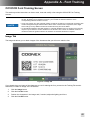
OCV/OCR Font Training Screen ....................................................................................................... 41
Image Tab .............................................................................................................................. 41
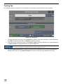
Training Tab ........................................................................................................................... 42
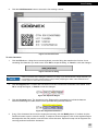
Font Tab ................................................................................................................................. 45
iii
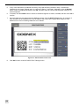
Difference Table Tab .............................................................................................................. 47
Appendix B - User Authentication
User Authentication ........................................................................................................................... 49
Creating In-Sight Users ......................................................................................................... 49
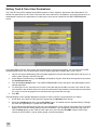
Setting Track & Trace User Permissions................................................................................ 50
Idle Timeout ....................................................................................................................................... 51
Appendix C - Creating an Audit Trail
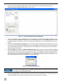
Creating an Audit Trail ....................................................................................................................... 53
Configure the Cognex Audit Message Demo Application....................................................... 53
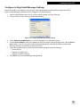
Configure In-Sight Audit Message Settings ............................................................................ 55
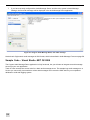
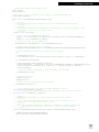
Sample Code – Visual Studio .NET C# 2008 ......................................................................... 56
Audit Message Format ........................................................................................................... 58
Event Messages ..................................................................................................................... 59
Change Messages.................................................................................................................. 60
Schema for Audit Messages................................................................................................... 61
Appendix D - Integrating the HMI Display Control
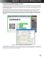
Integrating the HMI Display Control................................................................................................... 63
HMI Display Control Prerequisites.......................................................................................... 64
Adding the HMI Display Control to your Application ............................................................... 64
Using the HMI Display Control – Properties ........................................................................... 66
Programming the HMI Display Control ................................................................................... 66
iv
Track & Trace Overview
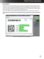
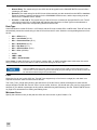
Description
In-Sight® Track & Trace works with your In-Sight vision system to form comprehensive identification and data
verification solution for labels on pharmaceutical and medical device packages. Combining high-performance ID
code reading, online quality grading for Data Matrix codes, and high reliability printed text verification, Track &
Trace has everything needed for product serialization applications. And with full support for GS1 data standards,
Track & Trace is prepared for the coming global traceability requirements.
Track & Trace features a ready-to-deploy user interface that makes it easy to configure and monitor runtime
operation using the Cognex VisionView® Operator Interface Panel or VisionView PC software. Developers can
quickly embed this same interface into a PC-based HMI or custom application interface using the included .NET
control.
Figure 1-1: Example Track & Trace Run Time Display
1
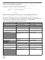
Contents
In-Sight Track & Trace includes several components, described in the following table:
Table 1-1: In-Sight Track & Trace Product Contents
Component
Description
In-Sight Track & Trace Single Unit Job
The essential component of In-Sight Track & Trace, this job file is pre-configured to inspect and
validate the data printed on a single label or package. Running on your In-Sight vision system, the
Single Unit job provides the user interface for configuring all inspection and communications
parameters, monitoring runtime performance, and initiating a batch changeover. A pre-trained font to
work with the sample labels is also included in the job file.
A license must be installed on each vision system that will run the Track & Trace job. Contact your
Cognex representative for details.
Cognex HMI Display Control
This .NET control integrates the Track & Trace user interface into a custom Windows application. The
"touch screen" friendly look-and-feel of the HMI Display Control is similar to that of the Cognex
VisionView Operator Interface Panel. An API is provided to expose selected features of the HMI
Display Control, based on the operator controls required in your deployment.
The In-Sight Software Development Kit (ISDK) is recommended for custom applications requiring
more comprehensive access and control of In-Sight vision systems than is provided with the HMI
Display Control. Contact your Cognex representative for details.
Cognex HMI Display Control Sample
Application
This executable program demonstrates the capabilities of the Cognex HMI Display Control for hosting
the Track & Trace user interface in your application. Source code is provided to help speed up your
integration. The HMI Display Control Sample application can also be used to help you start learning
how to set sup the Track & Trace Single Unit job for your inspection application.
Cognex Audit Message Demo Sample
Application
The Cognex Audit Message Demo demonstrates how audit messages can be received from one or
more vision systems on the network. Audit messages are time stamped data records (XML format) that
contain changes to system parameters, user logins and other system events, as necessary for FDA 21
CFR Part 11 compliance. Your application software constructs an audit message server to retrieve new
In-Sight audit messages, which you can then archive to a database or write to an audit trail file.
Cognex Audit Message Server Sample
Track & Trace installs a Visual Studio 2008 project containing sample code for an audit message
server at C:\Program Files\Cognex\In-Sight\In-Sight Track and Trace 1.0.1\Cognex Audit Message
Server\Sample Code.
In-Sight Explorer Configuration Utility
When In-Sight Explorer 4.4.0 or higher is already installed on a PC, the In-Sight Explorer Configuration
Utility can set default view to Spreadsheet View and enable the Audit Message Settings dialog in InSight Explorer.
Sample Labels
A printable PDF file containing 30 sample labels is provided, along with a set of 30 images of these
labels (.bmp format).
2
Track & Trace Overview
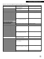
Requirements
The following table lists the requirements for installing and operating In-Sight Track & Trace:
Table 1-2: In-Sight Track & Trace Requirements
Requirement
Notes
In-Sight Micro series or 5000 series vision Track & Trace supports the following models :
systems running firmware 4.4.0 and
•
In-Sight Micro 1100, 1110*, 1400, 1410*, 1403, 1413*
higher1
•
In-Sight 5100, 5110*, 5400, 5401, 5403, 5410*, 5411*, 5413*, 5600, 5603, 5604,
5605, 5610*, 5613*
2
In-Sight Explorer software 4.4.0 and
higher
1
In-Sight Explorer is used to manage vision system network settings, update firmware, manage users,
enable Audit Message Settings, and more.
VisionView Operator Interface Panel
running firmware 1.3.0 and higher and
VisionView Operator Interface Panel and VisionView PC software support the following Track & Trace
features:
•
Font training
VisionView PC software 1.3.0 and higher3
•
Require In-Sight User Name to logon after timeout
•
Portuguese user interface (all the documentation is also available in Portuguese)
PC with 1GB RAM and Microsoft Windows Microsoft Windows Vista SP1 and Windows 7 are also supported.
XP SP3 (32-bit edition)
Microsoft Visual Studio 2008
Required to integrate the Cognex HMI Display Control into your HMI or custom application.
1. In-Sight firmware/software version 4.3.4 may work properly with Track & Trace 1.0.1; however, Cognex only tests and supports
Track and Trace 1.0.1 with In-Sight Explorer 4.4.0 and higher.
2. Track & Trace pattern fixture and label position inspection features are not available on In-Sight ID reader models (indicated by '*').
3. VisionView firmware/software version 1.2.0 may work properly with Track & Trace 1.0.1; however, Cognex only tests and supports
Track and Trace 1.0.1 with VisionView 1.3.0 and higher.
3
4
Getting Started
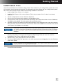
Install Track & Trace
This section describes how to install the In-Sight Track & Trace software on your In-Sight vision system and on the
PC that will be used to host the user interface. The following instructions assume that your In-Sight vision system
has 4.4.0 or later firmware version installed and is already available on the network.
1.
Install In-Sight Track & Trace 1.0.1 software.
2.
Install In-Sight Explorer 4.4.0 or later software. (This is only necessary if 4.4.0 or later is not already
installed.)
3.
Launch In-Sight Explorer from the Windows Start Menu.
4.
Log on to the vision system and navigate to the Spreadsheet View.
5.
From the Sensor menu, open the Active Cells Limit dialog and increase the number of cells to 7168 cells.
Click OK to exit the dialog. The vision system will automatically reboot.
6.
Locate the Track & Trace license you received from Cognex. From the Sensor menu, open the Licensing
dialog and enter the license in the Enter a new license field. Click the Add button to add the license to the
vision system. Click Close to exit the dialog.
NOTE
The license is a unique 48 character alphanumeric string encoded with the MAC address of a specific
vision system. You must install a license on every vision system that will run the Track & Trace job. If
you receive a “The license is not valid” error message, the license you are trying to enter is not valid for
the current vision system. Please contact the Cognex representative who issued the license for further
assistance.
7.
From the File menu, select the Open Job dialog. Navigate to the In-Sight Track & Trace installation
directory; the default is: C:\Program Files\Cognex\In-Sight\In-Sight Track and Trace 1.0.1\Job File.
Highlight the Track_Trace_Single.job file and click Open.
8.
Save the Track_Trace_Single.job file to the vision system.
9.
From the In-Sight Network tree, right-click on the vision system and select Properties. Note the IP address
of the vision system.
NOTE
For more information on using In-Sight Explorer, refer to the In Sight® Explorer Help, an online HTML
Help file provided on the In-Sight Explorer CD-ROM.
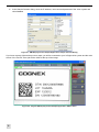
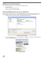
10. To verify that the installation was successful, launch the Cognex HMI Display Control Sample application
from the Windows Start Menu.
5
11. In the Sample Controls dialog, enter the IP address, user name and password of the vision system and
click Connect.
Figure 2-1: HMI Display Control Sample Application, Sample Controls Dialog
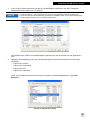
If you have correctly followed the previous steps, you will be connected to your In-Sight vision system and the main
screen of the Track & Trace job will be visible at the top of the image.
Figure 2-2: Cognex HMI Display Control Sample Application, Status Panel
6
Getting Started
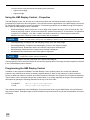
Set Up the Image
Before you can begin configuring Track & Trace, you need to obtain an image of a label. Click the Adjust Image
button, then click Focus to enter live acquisition mode. Position a label in the image, focus the lens and adjust the
image brightness until you have a clear image of the label data.
NOTE
You can also load an image or a job file on a vision sensor by dragging-and-dropping it onto the image
area of the Cognex HMI Display Control Sample application.
Figure 2-3: Live Acquisition Mode
7
8
Setting Up Track & Trace
This chapter describes how to configure Track & Trace to inspect label data and to output the results to an MES,
serialization database or PLC.
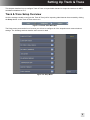
Track & Trace Setup Overview
All of the settings needed to configure the Track & Trace job for inspecting label data can be accessed by clicking
the Setup button on the Track & Trace main menu.
Figure 3-1: Track & Trace Main Menu
The Setup menu presents the list of screens you will use to configure all of the inspection and communications
settings. The following sections describe each screen in detail
Figure 3-2: Setup Menu
9
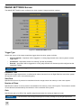
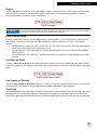
IMAGE SETTINGS Screen
The IMAGE SETTINGS screen configures the vision system’s image acquisition settings.
Figure 3-3: IMAGE SETTINGS Screen
Trigger Type
Selects the source of the image acquisition trigger when the vision system is Online:
•
Camera (default) – Acquisition will be triggered on a rising edge sensed at the vision system’s camera
trigger input.
•
Continuous – Acquisition will be “free running” (as fast as possible).
•
External – Acquisition will be triggered on a rising edge sensed at a discrete input bit configured as the
Acquisition Trigger.
NOTE
Continuous trigger is intended for demonstration mode only, and should not be used during production.
Exposure Time
Specifies the image exposure time, in milliseconds; when connected to an In-Sight 5604 line scan vision system,
the exposure time is set in microseconds (µsec).
Start Row
Specifies the first row of pixels to be transferred from the image sensor into memory on the vision system.
Number of Rows
Specifies the number of rows of pixels to be transferred into memory on the vision system. The maximum number
of rows allowed is determined by the resolution of the connected vision system.
Gain
Specifies the gain (0 to 255) of the amplifier stage that precedes the analog-to-digital converter.
NOTE
10
When connected to an In-Sight 5604 line scan vision system, the Gain setting may be incremented by
0.25 increments, with the range remaining from 0 to 255, providing for very fine gain adjustments.
Setting Up Track & Trace
Orientation
Selects the orientation of the image
•
Normal (default)
•
Mirrored horizontally
•
Flipped vertically
•
Rotated 180 degrees
NOTE
The In-Sight 5604 line scan vision system only supports Normal and Mirrored horizontally Orientation
settings. Choosing Flipped or Rotated will have no effect.
Line Trigger Type
Specifies the type of encoder. The Line Trigger Type control is supported only when connected to an In-Sight 5604
line scan vision system.
•
Hardware Encoder: specifies that the Steps Per Line setting and an external hardware encoder that will
be used to drive the line triggers.
•
Software Encoder (default): specifies that the Line Period setting will be used as a clock to drive the line
triggers at a defined interval.
Line Period/Steps Per Line
Specifies the time between lines in either microseconds (µsec) when the Line Trigger Type is set to Software
Encoder, or encoder steps when the Line Trigger Type is set to Hardware Encoder. The Line Period/Steps Per
Line control is supported only when connected to an In-Sight 5604 line scan vision system.
•
Line Period: specifies the period of time, in microseconds, per image line; 10.0 to 1,000,000 µsec (default
= 40 µsec) when the Line Trigger Type is set to Software Encoder.
•
Steps Per Line: specifies the number of encoder steps per image line; 0.25 to 256 (default = 40 µsec)
when the Line Trigger Type is set to Hardware Encoder.
NOTE
• To prevent missing line triggers, the Line Period value must be set so that the shortest time between
any two lines is 21.47 µsec greater than the Exposure setting (at a minimum of 1.33 µsec).
• The Steps Per Line value should be incremented by 0.5 for single line hardware encoders, and 0.25
for quadrature hardware encoders.
Encoder Acquisition Timeout
Specifies the maximum amount of time, in milliseconds, to acquire an image (0 to 300,000; default = 60,000). If the
image acquisition has not been completed within the specified time, the acquisition will be aborted and an
Acquisition Error will be issued. The Encoder Acquisition Timeout control is supported only when connected to an
In-Sight 5604 line scan vision system.
Clip Mode
Specifies an action if an image acquisition trigger is received, but the specified number of lines have not yet been
acquired. The Clip Mode control is supported only when connected to an In-Sight 5604 line scan vision system.
• When either Fill Black or Reduce Image Lines are selected, the In-Sight 5604 line scan vision system
may only receive acquisition triggers from the Camera Trigger.
NOTE
• The Fill Black option requires roughly 2 µsec per line of fill (e.g. 0.2 milliseconds for 100 lines). For
time critical applications, select the Reduce Image Lines option, or, if using the Fill Black option, keep
the fill under a few hundred lines.
•
No Clipping (default): specifies that the image trigger will be ignored and an "Acquisition error" event will
be generated.
•
Fill Black: specifies that the remaining lines will be filled with black pixels, and a new image will be
immediately started. An "Acquisition error" event will not be generated.
11
•
Reduce Image Lines: specifies that the current image will be reduced to the size of the number of rows
currently acquired, and a new image will be immediately started.
NOTE
12
For more information, see the AcquireImage topic in the In-Sight Explorer® Help file.
Setting Up Track & Trace
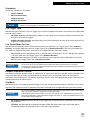
LOCATION TOOLS Screen
The LOCATION TOOLS screen provides optional tools that can help to locate the ID codes and OCV lines in the
image and check that the label itself is positioned correctly. By default, all the controls in the LOCATION TOOLS
screen are disabled.
NOTE
Location Tools are not available on In-Sight ID readers. When a Track & Trace job is loaded on an InSight ID reader, all of the selections in the LOCATION TOOLS screen will be inaccessible.
Figure 3-4: LOCATION TOOLS Screen
Pattern Fixture
The Pattern Fixture tool can be used to train a model of a feature that is present on every label. The position of this
pattern can then be used as a fixture from which to locate the ID codes and text printed on the label. Check the
Pattern Fixture box to train a model that can be used as a fixture.
Model
Click the X/Y button to select the area of the image containing the feature that will be trained as a model, then click
the Train button to teach the model. Make sure you select a feature that will be present in every image.
Search Region
Click the X/Y button to select the area of the image in which to search for a pattern that matches the trained model.
During operation, the pattern must be present within the Region to be found. If Pattern is selected as the Fixture for
the ID codes or OCV lines and the model cannot be found, the inspection will fail.
Minimum Score
Specifies the minimum acceptable score for finding the pattern in the image. If the Actual Score is lower than the
specified Minimum, the inspection will fail. Default = 60.
Label Position
Optionally, the Label Position tool can inspect whether a label has been correctly applied to a package. You can
configure the Label Position tool by locating label edges, an ID code or a pattern, and defining the range of
13
tolerances for the label position or skew. If the label is located outside of the specified area and/or at greater than
the specified angle, the inspection will fail even if the label can be located.
•
Label Edges (default): The label position will be determined relative to the edges of the image. Configure
the label edges using the Vertical and Horizontal Edges controls.
•
ID Code 1: The label position will be determined relative to the position of ID Code 1 in the image.
•
Pattern: The label position will be determined relative to the position of the pattern in the image.
NOTE
ID CODE 2 cannot be used for the Label Position tool.
Vertical Offset and Horizontal Offset
Specify the position tolerance by adjusting the Range (-) and Range (+) values, which defines minimum and
maximum allowable distance (in pixels) from the reference point. When None is selected for the Fixture (default),
the reference point is the upper-left corner of the image. When ID Code 1 is the selected Fixture, the reference
point is the upper-left corner of the code. When Pattern is the selected Fixture, the reference point is the center of
the pattern.
NOTE
• The Vertical and Horizontal Offset controls will not be enabled when the Label Position box is
unchecked, or when the Vertical and/or Horizontal Edge boxes are unchecked.
• If both the Vertical Offset and the Horizontal Offset checkboxes are disabled, the Label Position
tool only inspects whether the selected Label Position option has been found or not.
The location (in pixels, below Actual) will be displayed for each edge of the selected Label Position option that can
be located. When Edges are used without a fixture, or Pattern or ID code is used without Edges, the displayed
location will be relative to the image. When a pattern or ID code is used to fixture Edges, the displayed location will
be relative to the pattern or ID code. If one or both Offset checkboxes are enabled and an edge cannot be found, or
if an edge is located outside of the specified tolerance, the inspection will fail. The Range of offset varies depending
on the resolution of the camera.
NOTE
If Label Edges is the selected Label Position tool, and each edge of the label cannot be located, “Edge
Not Found” will be displayed.
Angle
If either the vertical or horizontal edge of the selected Label Position option can be found, the angle of the label (in
degrees, below Actual) will be displayed. Specify the angle tolerance by adjusting the Range (-) and Range (+)
values, which defines minimum and maximum allowable rotation (in degrees) of the label in the image. If the
checkbox is enabled and an angle is outside of the specified tolerance, the inspection will fail. Angle: -180 to 180,
default = -5.0 (Range -) and 5.0 (Range +).
Label Edges
The Label Edges controls are enabled only when Label Edges is the selected Label Position tool.
Vertical Edge and Horizontal Edge
Click the X/Y buttons to position and size the regions in which to search for the vertical and horizontal edges of the
label. If one or both edge checkboxes are enabled and an edge cannot be found, the inspection will fail.
NOTE
• If the Vertical Edge checkbox is disabled, the Horizontal Offset control is grayed out. If the
Horizontal Edge checkbox is disabled, the Vertical Offset control is grayed out.
• If both the Vertical Edge and Horizontal Edge checkboxes are disabled, the Label Position
inspection will always pass.
Fixture
Optionally, the Fixture tool can be used to inspect whether the label is positioned correctly relative to a nearby,
visible feature on the package regardless of where the package is in the image. If the fixture cannot be located, the
inspection will fail.
14
Setting Up Track & Trace
•
None (default): No Fixture will be used. The label position will be located by its Vertical and/or Horizontal
Edge locations in the image.
•
Pattern: The label position will be located by its Vertical and/or Horizontal Edge locations relative to the
trained Pattern in the image.
•
ID Code 1:The label position will be located by its Vertical and/or Horizontal Edge locations relative to the
position of the ID code in the image.
• Always reposition the Vertical and Horizontal Edges after selecting Pattern or ID Code 1 for the
Fixture. Otherwise, selecting a fixture may cause the Vertical and Horizontal Edge’s regions to shift to
new locations in the image that do not contain the edges, and inspection may fail.
NOTE
• When attempting to reposition the Vertical and Horizontal Edges, the regions may be out of the image
area. In this circumstance, press the Pan/Zoom button to enter Pan/Zoom mode (if using the Cognex
HMI Display Control or VisionView application). Click the Zoom Out button repeatedly until the
region appears within the image area, and click OK. Then, reposition the region using Interactive
Graphics Mode.
15
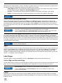
ID CODE 1 and ID CODE 2 Screens
Track & Trace can read up to two 1D or 2D codes on a single label or package, validate the encoded data, and
grade the quality of Data Matrix codes. Each ID code is set up using separate screens; ID CODE 1 and ID CODE
2. The contents of both screens are identical. By default, all the controls in the ID CODE 1 and the ID CODE 2 are
disabled.
Figure 3-5: ID CODE 1 Screen
ID Code Reading Settings
The following settings must be configured to read an ID code, which is a pre-requisite for validating the encoded
data and for grading the quality of a Data Matrix code.
Enable
Check this box to use the ID code. When the check box is disabled, the ID Code will not be used in determining the
overall inspection result. However, the inspection will fail if the ID Code is disabled, but ID Code has been selected
as the Label Position tool in the LOCATION TOOLS screen, as the Fixture or as a Data Source in the OCV LINES
screen.
Name
Enter the name of the ID Code. This name appears in the title of the ID CODE screen, which is useful if ID CODE
1 and ID CODE 2 are configured to read different code types. The default name for the ID CODE 1 screen is "Data
Matrix", and the default name for the ID CODE 2 screen is "Code 2".
Fixture
Specifies whether the Pattern Fixture trained in the LOCATION TOOLS screen or the ID code configured in the ID
CODE 1 screen will be used to position the ID code Region in the image.
•
None (default): Fixture will not be used. A fixture is usually not necessary when reading a 2D code, such
as Data Matrix.
•
Pattern: The Pattern Fixture will be used. A Pattern Fixture is most useful when reading a 1D barcode.
•
ID Code 1 (ID CODE 2 screen only): The ID code will be used.
16
Setting Up Track & Trace
Figure 3-6: Position and Size the ID Code Region
Region
Click the X/Y button to define the area of the image in which to search for the ID code. Move and resize the region
using the buttons in the panel on the right, or directly using the interactive region graphic displayed on top of the
image.
NOTE
• Always reposition the ID code Region after selecting Pattern or ID Code 1 for the Fixture. Otherwise,
selecting the Pattern or the ID Code 1 Fixture may cause the ID code Region to shift to a new
location in the image that does not contain the ID code, and reading may fail.
Code Type
Select the type of 2D code or 1D barcode to read.
•
Learn Mode
•
Data Matrix
•
Pharmacode
•
Code 128 (including GS1-128)
•
Code I2of5 (including GS1 ITF-14)
•
Code 39
•
EAN
•
GS1 DataBar (formerly called RSS)
•
UPC
•
QR Code
To automatically learn the Code Type, select Learn Mode from the list and then click the Learn button. A “Code
Learned <type>)” message will be displayed when learning is successful. If “Code Not Learned” is displayed, this
indicates that Track & Trace could not determine the Code Type for some reason (for example, because the ID
code is located outside of the Region).
Read Timeout
Specifies the maximum amount of time (in milliseconds) allowed to read the ID code. The inspection will fail if the
ID code cannot be read before the Read Timeout has been reached. The maximum Read Timeout is 2000
milliseconds.
17
Data Validation Settings
Optionally, the data contained in the ID code can be validated to ensure that it has been encoded according to
either the GS1 or the FDA serialized National Drug Code (sNDC) standard, and that the decoded data matches the
data that is expected.
NOTE
• ID Code 1 must be used for codes that contain GS1 or sNDC data. If ID Code 2 is used for GS1 or
sNDC data, and GS1 Data or sNDC Data is a selected Data Group in the OUTPUT FORMAT screen,
the data will not appear in the output string.
• The NDC number can also be included as part of the GTIN data element in a GS1 code. If this is the
case, select GS1 for the Data Format.
Data Format
•
GS1
Select GS1 if the data in the ID code has been encoded according to GS1 standards (http://www.gs1.org/).
The encoded data must meet the following requirements:
• The data string must begin with the FNC1 symbology identifier character (which is never displayed or
printed).
• All of the data elements in the ID code must be preceded by a valid GS1 Application Identifier (AI),
which is a two or three digit number, depending on the AI.
• All of the data elements must contain the correct number of characters for their corresponding AI.
• For AIs that specify variable-length data, an FNC1 field separator must immediately follow the data
element.
•
sNDC
Select sNDC if the data in the ID code has been encoded according to FDA serialized National Drug Code
(http://www.fda.gov/downloads/RegulatoryInformation/Guidance/UCM206075.pdf). The encoded data
must meet the following requirements:
• The data string must consist of a 10-digit NDC number immediately followed by a unique serial number
of up to 20 alphanumeric characters.
• The three sections of the NDC number can be separated by a space or a dash; however, the data string
must not contain any other special formatting, application identifiers or checksum characters.
•
None
Select None if the data in the ID code was not encoded according to either the GS1 or the FDA serialized
National Drug Code (sNDC) standard.
NOTE
If the encoded data fails to meet one or more of the requirements, the ID code is not compliant with the
selected Data Format. The inspection will fail even though the contents of the ID code can be read.
Match Read Result
The data contained in the ID code can be compared to a known data string. If the decoded data does not match the
expected data, the inspection will fail.
•
Manual Entry: The match string will be typed into the CHANGE BATCH screen when a new batch is
initiated.
•
Ethernet: The match string will be received over the network from the MES or a serialization database.
Ethernet Communication Channel 1 must be configured in the COMMUNICATION screen, and the input
string must be configured in the FORMAT INPUT screen.
•
None: The decoded data does not need to be compared to a known data string.
Check Serial Number
When the Data Format is GS1 or sNDC and the ID code contains a serial number (for example, GS1 Application
Identifier 21), the serial number can be checked to ensure that it is valid for the current batch.
18
Setting Up Track & Trace
•
S/N Fixed: The serial number contained in the ID code must match a known serial number. The match
string will be received over Ethernet from the MES or serialization database, or entered manually in the
CHANGE BATCH screen, depending on the current Match Read Result selection.
•
S/N Different Than Previous: The serial number in the current inspection must be different than the serial
number that was read in the previous inspection.
•
S/N Within Range: The serial number must be included within a defined range of values. The minimum
and maximum values for the range will be received over Ethernet from the MES or serialization database,
or entered manually in the CHANGE BATCH screen, depending on the current Match Read Result
selection.
•
Don’t Check S/N: The serial number does not need to be checked, the Data Format is None, or the GS1
data in the code does not include a serial number.
Data Matrix Code Grading Settings
Optionally, Track & Trace can grade the quality of 2D Data Matrix codes while the vision system is operating
Online. This feature can be used to detect changes in the quality of the ID code, which could indicate that the
printing system requires servicing.
NOTE
Online grading detects relative changes in Data Matrix code quality, but it does not measure absolute
quality. A verifier is needed to accurately measure the quality of a Data Matrix code. Contact your
Cognex representative for information on DataMan verifiers.
Figure 3-7: Data Matrix Code Grading Settings
Grading
Selects the standard to use for Online of grading Data Matrix code quality. Typically, ISO 15415 grading metrics
should be selected for Online quality inspection of Data Matrix codes printed on pharmaceutical and medical
device packaging.
Select ISO 16022 grading metrics if more rigorous code quality inspection is required. However, the ISO 16022
grading standard requires a precisely controlled lighting system to ensure accurate results, and is generally better
suited to Offline code quality inspection.
AIM Process Control and AIM Contract Compliance are used to grade direct part marks (DPM), such as on
medical instruments.
19
Select None (default) if the ID code type is not Data Matrix, or if quality grading is not required.
Minimum Grade
Select the minimum grade (A - F) required for passing the Data Matrix code quality inspection. Each of the
Individual Grades must meet or exceed the Minimum Grade, or the inspection will fail. For example, if the
Minimum Grade is C, then all of the nine individual metrics must score C or better or the inspection will fail.
Select Individual Grades to specify the minimum grade for quality metric. This allows you to fine tune the Data
Matrix code quality inspection criteria by requiring higher or lower grades for specific metrics. For example, the
Grid non uniformity metric could have a minimum grade of D, and all the other metrics have minimum grades of C.
Individual Grades
If the Minimum Grade is set to Individual Grades, a minimum grade can be individually specified for each of the
nine quality metrics:
•
Contrast
•
Fixed Pattern Damage
•
Modulation
•
Grid Non Uniformity
•
Horizontal growth
•
Vertical growth
•
Non Uniformity
•
Unused EC
•
RefDecode
During inspection, each quality metric must score at or above its specified grade, or the inspection will fail.
NOTE
20
For more information on Data Matrix code grading, see the “Verifying 2D Symbol Quality” topic in the
In-Sight Explorer® Help file.
Setting Up Track & Trace
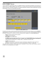
OCV LINES Screen
Track & Trace can verify up to six lines of printed text on a single label or package.
Figure 3-8: OCV LINES Screen
Fixture OCV Lines
For reliable OCV performance, the position of the printed text in the image must be highly repeatable from one
image to the next. Using a fixture ensures that the Region for each OCV line will always be located around the text,
even if the text position varies slightly in successive images.
•
ID Code 1: OCV lines will be fixtured relative to the location of ID Code 1 in the image. This selection offers
the fastest performance if a Data Matrix code is printed on the label.
•
Pattern: OCV lines will be fixtured relative to the location of the Pattern in the image, if a model was
trained in the LOCATION TOOLS screen.
•
None: ID Code 1 is not enabled, or a Pattern Fixture is not supported on the vision system.
OCV Line Settings
Up to six OCV lines can be included in the inspection. Each OCV Line is configured individually.
Line #
Enable the checkbox next to each of the lines that will be configured to verify printed text. If the checkbox for a Line
is disabled, that line will not be included in the inspection. By default, all the checkboxes are disabled.
Name
Enter a name reference for the OCV line. Optionally, when the Use Name as Prefix box is checked this name will
be added to the OCV match string for the OCV line.
Data Source
Every OCV line must have a match string to specify the characters to match during the inspection. The match
string for all OCV lines can be from the same Data Source, or OCV lines can have different data sources.
21
•
Manual Entry: The match string for the OCV line will be typed into the CHANGE BATCH screen before
initiating a new batch.
•
Ethernet: The match string for the OCV lines will be received over the network from the MES or database.
Ethernet Channel 1 must be configured in the COMMUNICATION screen, and the input string must be
defined in the FORMAT INPUT screen.
•
ID Code 1 or ID Code 2: The match string for the OCV line is contained in the specified ID code. The ID
code must contain GS1 or sNDC data that matches the printed text. A Data Type must be selected to
automatically extract the corresponding data from the ID code.
Data Type
If the Data Source is either ID Code 1 or ID Code 2 and the ID code contains GS1 or sNDC data, Track & Trace will
automatically extract the match string for the OCV line from the ID code. Select the corresponding data item from
the list:
•
GS1 - GTIN (AI 01)
•
GS1 - Lot Number (AI 10)
•
GS1 - Production Date (AI 11)
•
GS1 - Best Before (AI 15)
•
GS1 - Exp Date (AI 17)
•
GS1 - Serial Number (AI 21)
•
GS1 - Price (AI 390n)
•
CIP13
•
sNDC - NDC
•
sNDC - Serial Number
Select None if neither ID Code 1 nor ID Code 2 contains GS1- or sNDC-compliant data. In this case, the entire
string contained in the ID code will be used as the match string for the OCV line.
• The Data Type will be ignored if Manual Entry or Ethernet are specified for the Data Source.
NOTE
• Select the CIP13 Data Type when the ID code contains a GS1 GTIN, but the printed text is in the
CIP13 format. The CIP13 Data Type will automatically strip the leading 0 from the GTIN so that it can
be used as the match string for the printed CIP13.
Font
Select the font to use for this OCV line. Track & Trace supports up to four fonts in a single job, and there is no
requirement that the same font be used for all lines.
The Track_Trace_Single.job includes a pre-trained font (Font #4, Demo), which are designed to work with the
sample images included with Track & Trace. In most cases, however, you should train your own font using actual
samples of your labels or packages as they will be marked during manufacturing. See the TRAIN FONTS Screen
on page 25 for instructions on training and editing fonts.
Minimum Score
Specify the minimum score (0-100) that the OCV line must receive to pass. Default = 70.
22
Setting Up Track & Trace
Region
Click the X/Y button to define the area of the image in which to locate the OCV line. The Region should be sized
large enough to contain all of the characters, but not so large that it encompasses any potentially confusing
background features, or portions of other characters.
Figure 3-9: Region
NOTE
Always reposition the Region for each OCV Line after selecting Pattern for the Fixture. Otherwise,
selecting the Pattern Fixture may cause the OCV Line Regions to shift to a new location in the image
that does not contain the printed text, and the inspection may fail.
Current Match String
For each enabled OCV line, the Current Match String will be displayed if it can be determined. A blank Current
Match String for an OCV Line indicates that the match string cannot be determined for one of the following
reasons:
•
The Data Source is set to ID Code 1 or ID Code 2, but the code cannot be read. Go to the appropriate ID
CODE screen and verify that the settings are correct.
•
The Data Source is set to Manual Entry, but the match string has not yet been entered in the CHANGE
BATCH screen.
•
The Data Source is set to Ethernet. The match string will be updated after a batch changeover has been
initiated.
Use Name as Prefix
Check the Use Name as Prefix box to include the Name of the OCV Line in the match string that will be used to
inspect the printed text. The Region for each OCV Line must be resized to include all of the characters in the match
string.
Figure 3-10: Use Name as Prefix
Use Comma for Decimal
Check the Use Comma for Decimal checkbox if a comma (,) is used to represent a decimal point in an OCV line
containing price. This checkbox is only enabled when the GS1 - Price Data Type is selected.
Tune Fonts
Click Tune Fonts to rescale the fonts for each OCV Line based on the characters in the current image. This step is
necessary if you have made any changes to your optical or mechanical configuration such that the size of the
characters in the image is different than when the font was initially trained, or if the printed font size has changed.
23
DATE FORMAT Screen
The GS1 standard formats all date values as YYMMDD. But dates on pharmaceutical labels are often printed in a
different format. The DATE FORMAT screen allows you to convert the GS1 date format to the actual format that is
printed on the label. This makes it possible to use the date information contained in a GS1-standard ID code as the
match string for OCV lines of printed date information.
Figure 3-11: DATE FORMAT Screen
To convert a GS1 date to match the format of the text printed on your label, make selections from the Setup the
Date Format lists to define the format of the GS1 date as it is printed on your label, including separator characters,
punctuation and spacing. For reference, the auto-generated result is displayed in the Converted Date field.
•
Empty: No date information will be included.
•
Year(YY): The two-digit year.
•
Month(MM): The two-digit month.
•
Cust(MM): The month, converted according to the entries in the Custom Month table. For example, if MM
is “12”, the default Cust(MM) would be “Dec”. If needed, click on each entry in the Month custom table to
change the text for each month, for example “DEC” or “December” instead of “Dec”.
•
Day(DD): The two-digit day.
•
String: User-definable text. This selection must be used when the printed date contains spacing or
punctuation, or the year is printed in YYYY format (see examples in Table 3-1 on page 25).
Using these above selections in various combinations, it is possible to convert a GS1 date to match the format of
the date as it is actually printed on your labels.
24
Setting Up Track & Trace
Table 3-1: GS1 Date Conversion Examples
Printed Date
Format
Date Format Selections
MM/YY
Month(MM)
String “/”
Year(YY)
Empty
Empty
Empty
Empty
MM/YYYY
Month(MM)
String “/”
String “20”
Year(YY)
Empty
Empty
Empty
DD/MM/YYYY
Day(DD)
String “/”
Month(MM)
String “/”
String “/20”
Year(YY)
Empty
DD.MM.YY
Day(DD)
String”.”
Month(MM)
String “.”
Year(YY)
Empty
Empty
Month-YYYY
Cust(MM)
String “-“
String “20”
Year(YY)
Empty
Empty
Empty
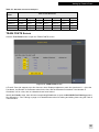
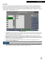
TRAIN FONTS Screen
Click the Train Fonts button to open the TRAIN FONTS screen.
Figure 3-12: TRAIN FONTS Screen
A Track & Trace job supports up to four fonts at a time. Displayed adjacent to each font (numbered 1 – 4) are the
Font Name, the Number of Characters trained in the font, and the Character Set trained. If the Number of
Characters is 0 for a font, then no characters have been trained.
Identify the Font # to train, then click the corresponding Font button to open the OCV/OCR Font Training screens.
See Appendix A - Font Training on page 41 for detailed instructions for training and editing fonts using the Track &
Trace interface.
25
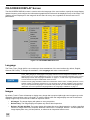
ON-SCREEN DISPLAY Screen
The ON-SCREEN DISPLAY screen is used to select the language of the user interface, specify the image display
update frequency, and configure the informational graphics and text that will be displayed on top of the image. The
graphics and text displayed on the image will be the same for every user, regardless of their access level or
permissions.
Figure 3-13: ON-SCREEN DISPLAY Screen
Language
The Track_Trace_Single.job file can contain up to three translations of the user interface (by default, English,
German and French). To change the translation, click Language and make a new selection.
NOTE
• This Language selection only changes the localization of the text contained in the
Track_Trace_Single.job. Changing this Language selection will not change the localization of the
Status Panel in the Cognex HMI Display Control. To change the language localization of the Cognex
HMI Display Control, see Language Localization on page 71, or refer to the Cognex HMI Display
Control Reference help file installed with Track & Trace.
• Several user language translation tables are included with Track & Trace, including German, French,
Spanish, Italian, Portuguese and Korean. If your language is not already available in the Language
list, you can replace the languages in a Track & Trace job with up to three different languages. For
information on how to replace the language tables, see Language Localization on page 71.
Images
By default, Track & Trace will attempt to display every image that is acquired (although some images may not be
displayed if the acquisition rate is very high). To reduce network traffic the image display rate can be reduced to
display images only at set intervals or after an inspection failure.
•
All Images: The image display will update on every acquisition.
•
Defects Only: The image display will update only after a failed inspection.
•
Defects / 50 /100 /200 /500: The image display will update after every failed inspection, or after a specified
number of images have been acquired, whichever comes first. For example, Defects / 100 will update the
image display after every 100 acquisitions, or whenever an inspection failure occurs.
26
Setting Up Track & Trace
Display Items
Click the check box next to an item to include it in the on-screen display. For most items you can select the Display
Color and define the Image Position. Note that for some items, the Display Color and Image Position are
determined automatically.
Inspection Result
Displays the overall pass/fail result for the inspection. PART OK is displayed in the color you choose if all of the
individual inspections pass. DEFECT ON [failed inspections] is displayed in red if one or more individual
inspections fail.
Statistics
Displays the Total number of inspections, Passed inspections and Failed inspections for the current batch. The
counters are automatically reset to zero when a new batch is initiated.
Batch Details
Displays the Name and Current Match String for each of the OCV lines enabled in the OCV LINES screen.
Regions
Displays the search regions for the Pattern Fixture, ID Code 1 and ID Code 2, and OCV lines, if enabled.
Line Speed
Displays the inspection rate, in parts per minute.
Processing Time
Displays the speed of the last inspection, in milliseconds.
ID Code – Result String
Displays the data contents of the ID code after a successful read. If the Data Type for the ID code is GS1, the
Result String will be displayed with the GS1 application identifiers included.
ID Code – GS1 Data
Displays the data contents of a GS1-standard ID code after a successful read. The data is displayed along with the
descriptions for its GS1 application identifiers. The Data Type of the ID code must be GS1.
ID Code – sNDC Data
Displays the data contents of an sNDC-standard ID code after a successful read. The Data Type of the ID code
must be sNDC.
ID Code – Overall Grade
Displays the overall quality Grade Value (A – F) after successfully reading a Data Matrix code. Grading must be
enabled in the corresponding ID CODE screens. The grade is displayed in red if it scores below the specified
Minimum Grade.
ID Code – Individual Grades
Displays the individual quality grades (A – F) for each of the 9 quality metrics after successfully reading a Data
Matrix code. Grading must be enabled in the corresponding ID CODE screens. Individual Grades are displayed in
red if they score below their specified minimums.
Figure 3-14: ID Code - Individual Grades
27
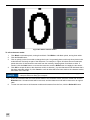
ID Code – Grading Graphics
Displays color-coded error graphics on top of the Data Matrix code after a successful read. Grading must be
enabled in the corresponding ID CODE screens.
A colored square indicates the grade for the Modulation metric, according to the quality grading standard selected
in the ID CODE screen. The color of the square is determined by the grade:
•
No square – A
•
Blue square – B or C
•
Yellow square – D
•
Red square – F
A red X represents a bit error, which is a white bit where a black bit is expected and vice-versa.
OCV – Characters
Displays a box around each character position in each OCV line, and the character that was matched at each
position. Correctly matched characters are displayed in green and incorrect matches are displayed in red.
Figure 3-15: OCV - Characters
OCV – Character Scores
Displays the match score for each character in each OCV line.
OCV – Match String/Region
Displays the Region and Match String for each OCV line. If one or more character matches are incorrect, the
Region, the Match String and the incorrectly matched characters will be displayed in red.
28
Setting Up Track & Trace
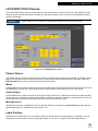
COMMUNICATION Screen
Before Track & Trace can exchange data with MES software, a database or PLC, the appropriate settings must be
configured in the COMMUNICATION screen.
Figure 3-16: COMMUNICATION Screen
Ethernet Communication Channel 1 / Channel 2
Track & Trace can receive batch setup information and send out inspection results over Ethernet. Incoming batch
setup information is defined in the INPUT FORMAT screen. Outgoing inspection results are defined in the
OUTPUT FORMAT screen.
Mode
For each Ethernet Communication Channel, select the protocol and specify if it will be used to send or receive
data. Both Channel 1 and Channel 2 support standard TCP/IP. Channel 1 also supports protocols used to
exchange data with the most commonly used PLCs, including EIP, PROFINET, and Modbus TCP/IP. Additionally,
Channel 1 supports receiving batch information using the Native Mode command, Send Message.
NOTE
The Send Message command must be issued in the format SM"[Batch Data]"2. Batch Data is userdefined in the INPUT FORMAT screen. Example: SM"@1-00012345679995-10JA28A-1212311234567890181/"2.
Channel 1 can be configured for Receive only, Send only or Send/Receive. Channel 2 can be Unused or
configured for Send Only.
Note the following:
•
When Modbus is the selected Mode for Channel 1, the byte order must also be selected. Choose Big
Endian, Little Endian, Big Endian (16-bit swap), or Little Endian (16-bit swap) to match the settings
used by the remote device.
•
When Channel 1 is Receive only or Send/Receive, check Acknowledge to return a message
acknowledgement to the sender when a message is received with the correct input format. If a message is
received with an incorrect input format, Track & Trace will reply with a “FORMAT ERROR” message. In this
case, verify that the format of the input string (as defined in the FORMAT INPUT screen) matches that of
the message that is actually being received.
29
•
When Native Mode is the selected Mode for Channel 1, the Acknowledge checkbox is disabled.
NOTE
For more information on these communications protocols, see the Communications Reference topic in
the In-Sight® Explorer Help file.
Port, Packet Type, Timeout
For each Channel, configure the Port, Packet type, and Timeout settings to match the settings used by the devices
with which Track & Trace is communicating.
Digital Outputs
Track & Trace allows up to 10 digital outputs to be used to signal pass/fail conditions to a PLC, switch or other
automation control. The 10 outputs are represented along two rows, numbered Line 0 – 4 and Line 5 – 9. For each
output line, select the pass/fail condition on which the output line will be activated. The available conditions are:
•
Unused: The output will never be activated.
•
Part OK: The overall inspection passed.
•
Part NOK: The overall inspection failed.
•
Read C1 OK: ID Code 1 was read successfully.
•
Read C1 NOK: ID Code 1 could not be read.
•
Grade C1 OK: ID Code 1 passed the code quality inspection.
•
Grade C1 NOK: ID Code 1 failed the code quality inspection.
•
Read C2 OK: ID Code 2 was read successfully.
•
Read C2 NOK: ID Code 2 could not be read.
•
Grade C2 OK: ID Code 2 passed the code quality inspection.
•
Read C2 NOK: ID Code 2 failed the code quality inspection.
•
OCV OK: All of the enabled OCV Lines were successfully verified.
•
OCV NOK: One or more of the enabled OCV Lines could not be verified.
•
Position OK: The Label Position inspection passed.
•
Position NOK: The Label Position inspection failed.
NOTE
The number of available outputs depends on whether an In-Sight I/O module is connected to the vision
system. Without an I/O module, only the two, built-in high speed outputs on the vision system are
available. See your Cognex representative to increase the number of outputs available to your vision
system using an In-Sight I/O module.
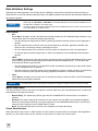
Save Images via FTP
Check the Save Images via FTP box to enable Track & Trace to transmit inspection images to a remote FTP
server for archiving or Offline failure analysis.
Host Name
Enter the host name (or IP address) of the FTP server on the network where the image files will be saved.
User Name, Password
Enter the login credentials for the FTP server where the image will be saved. The user does not need to exist on
the vision system.
Format
Select BMP to save images in Windows bitmap format (.BMP extension). Select JPEG to save images in standard
encoded format (.JPG extension).
30
Setting Up Track & Trace
Filename
Specify the format of the image filename by defining the contents of up to five fields.
•
Empty: The field will not be used.
•
String: The field will contain user-definable text.
•
Lot Number: The field will consist of the lot number extracted from the GS1-standard ID code (if
available).
•
OCV Line 1…6: The Name of the selected OCV Line, as specified in the OCV LINES screen.
•
Date/Time: The vision system date and time. Requires that the vision system is setup to have its time set
by an SNTP server on the network.
•
MAC Address: The unique identifier of the vision system.
•
Host Name: The network name of the vision system.
•
Counter: The 6-digit number of the last inspection, in nnnnnn format. When Counter is also a selection in
the OUTPUT FORMAT Screen, this allows inspection results to be associated with the corresponding
image.
Folder
Specify the folder location on the FTP server where the images will be saved.
Part OK, Part NOK
Check Part NOK to save images from failed inspections. Check Part OK to save images from passed inspections.
NOTE
For more information, see the WriteImageFTP topic in the In-Sight Explorer® Help file.
31
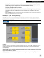
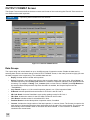
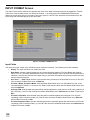
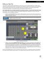
OUTPUT FORMAT Screen
The Output Format screen defines the data contents and format of the result string that Track & Trace sends out
over Ethernet after each inspection.
NOTE
If Ethernet Communication Channel 1 is set to Send or Send/Receive and Channel 2 is enabled, the
output string will be transmitted on both channels.
Figure 3-17: OUTPUT FORMAT Screen
Data Groups
The output string can include data from up to six different sets of inspection results. Enable the data sets by
selecting them from the six lists at the top of the OUTPUT FORMAT screen, in the order (from left to right) you want
the data to appear in the output string. The available data sets are:
•
Empty: No data will be included at this position.
•
String: Prepends a user-defined text string to the succeeding data in the output string. When String is a
selected Data Group and the Sep Char checkbox is enabled, a separator character is not appended to the
text string. For example, if String "Test", Counter (with a current value of "000000") and Insp.Result are
the selected Data Groups and the Sep Char checkbox is enabled, the Sample Output would be
"Test000000-1".
•
Insp. Result: Outputs a 1 if the overall inspection passed, or a 0 if the inspection failed.
•
ID Result: Includes pass/fail and read results for ID Code 1 and ID Code 2.
•
2D Code Grade: Includes Data Matrix code quality grading results for ID Code 1.
•
GS1 Data: Includes the values for the GS1 data encoded in the ID codes.
•
OCV Result: Includes results for all enabled OCV lines.
•
Position Result: Includes label position inspection results, if enabled.
•
Counter: Includes the 6-digit number of the last inspection, in nnnnnn format. The Counter is equal to the
total number of inspections that have been performed since the start of the current batch. The counter will
automatically reset to 000001 when a new batch has been initiated, or if the maximum of 999999 is
reached in the current batch.
32
Setting Up Track & Trace
•
Custom: Includes user-defined data in the output string. The custom data is defined in cell A300 of the
Track & Trace job file.
•
sNDC Data: Includes the values for the sNDC data encoded in the ID codes.
• If Ethernet Communication Channel 1 is set to Send or Send/Receive and Channel 2 is enabled, the
output string will be transmitted on both channels.
NOTE
• ID Code 1 must be used for codes that contain GS1 or sNDC data. If ID Code 2 is used for GS1 or
sNDC data, and GS1 Data or sNDC Data is a selected Data Group, the data will not appear in the
output string.
Inspection Results
As described in the preceding section, the inspection results that are available to include in the output string
depends on which Data Sets have been selected.
ID Code 1 / ID Code 2
If ID Result is one of the selected Data Sets, either or both of the ID Code 1 and ID Code 2 inspection results are
enabled, depending on which ID codes are enabled. Inspection results for each ID code are configured separately.
Check Pass/Fail to send the result of the ID Code read. The result will be 1 if the ID code was read successfully
and 0 if the ID code could not be read.
Check Match OK/NOK to send the result of the Match Read Result inspection for the ID Code. The result will be 1
if the ID code passed the Match Read Result inspection, or if Match Read Result in the ID CODE screen is set to
None. The result will be 0 if the ID code fails the Match Read Result inspection.
All or part of the ID Code read result can be included in the output string. Select Full String to include the entire
read result in the output. Select Partial String to transmit a substring. If Partial String is selected, the starting and
ending position of the substring must be defined:
•
Index Start Char: Specify the position in the Full String of the first character of the substring. For example,
if the Full String is of the format nnnnnnaaa and you want to output only the alpha characters, the Index
Start Char would be 6 because the first alpha character is the 7th character in the Full String (indexing
starts at 0).
•
# of Chars: Specify the number of characters to include in the Partial String. In the previous example of the
string nnnnnnaaa, the # of Chars would be 3 to include all of the alpha characters.
Code Grades
If one of the selected Data Sets includes 2D Code Grade, the Grading inspections results for ID Code 1 are
enabled.
NOTE
Grading inspection results for ID Code 2 cannot be included in the output string.
Check the Pass/Fail box to send the result of the ID Code 1 Grading inspection. The result will be 1 if the overall
grade for the ID Code 1 Grading inspection meets or exceeds the Minimum Grade. The result will be 0 if the overall
grade for the Grading inspection falls below the Minimum Grade.
Check Overall Grade to include the overall letter grade (A – F) for the Grading inspection.
Check Individual Grades to include the letter grade (A – F) for each of the 9 quality metrics measured during the
Grading inspection. The Individual Grades are concatenated in the following order:
•
Contrast
•
Fixed Pattern Damage
•
Modulation
•
Grid Non-uniformity
•
Horizontal Growth
•
Vertical Growth
33
•
Non-Uniformity
•
Unused Error Correction
•
Reference Decode
Check Numeric Values to include the actual measurements on which the individual quality metrics are graded, in
the form n.nnn.
NOTE
For information on how the quality metrics are measured and graded, refer to the Verifying Symbol
Quality topic in the In-Sight Explorer® Help file.
GS1 Data
If one of the selected Data Sets includes GS1 Data, the output string can contain the values for up to five GS1 Data
items, in any order you choose:
•
GTIN
•
Lot Number
•
Production date
•
Best Before date
•
Exp Date
•
Serial Number
•
Price
sNDC Data
If one of the selected Data Sets includes sNDC Data, the output string can contain the values for up to two sNDC
Data items, in any order you choose:
•
sNDC - NDC
•
sNDC - Serial Number
OCV Result
If OCV Result is one of the selected Data Sets, the output string can contain OCV inspection results.
Check the first Pass/Fail box to include the overall OCV inspection result in the output string. The result will be 1 if
all of the individual OCV line inspections pass. The result will be 0 if one or more OCV line inspections fail.
To include inspection results for each of the individual OCV lines:
•
Check the second Pass/Fail box to include the inspection results for each OCV line. For each OCV line,
the result will be 1 if the inspection passes. The result will be 0 if the inspection fails.
•
Check String to include the match string that was used for each OCV line inspection. The String will follow
the Pass/Fail result for the OCV line in the output string, if checked.
•
Check Char Scores to include the match scores (00 – 99) at each character position, for each OCV line.
The Char Scores will follow the Pass/Fail and String results in the output string, if checked.
Position Result
If Position Result is one of the selected Data Sets, the output string can contain the Label Position inspection
results.
Check the first Pass/Fail box to include the Label Position inspection result in the output string. The result will be 1
if the label position is within the tolerances specified in the LOCATION TOOLS screen. The result will be 0 if the
vertical or horizontal position of the label or the label rotation is outside of the specified tolerances.
To include the actual label position data in the output string:
•
Check Horizontal Offset to include the image pixel row at which the label edge was located.
•
Check Vertical Offset to include the image pixel column at which the label edge was located.
•
Check Angle Value to include the angle of rotation for the label in the image.
All label position data is in the form nnnn.nn.
34
Setting Up Track & Trace
Insp. Result
If Insp. Result is one of the selected Data sets, the output string can contain the overall Track & Trace inspection
result, and for failed inspections, an error code to indicate failure cause.
Check Pass/Fail to include the overall inspection result in the output string. The result will be 1 if all of the
individual inspections pass. The result will be 0 if one or more of the individual inspections
Check Error Code to include a numeric identifier in the output string when the inspection fails. The Error Code is a
6-digit counter in the form of nnnnnn. Every failed inspection will increment the counter by one. The Error Code
resets to 000000 when a new batch is initiated. The Error Code is always 000000 for passed inspection results.
Separator
Specify the ASCII decimal values for the starting, ending and separator characters that will be used to format the
output string.
NOTE
When String is selected in the Data Groups and the Sep Char checkbox is enabled, a separator
character is not appended to the text string.
35
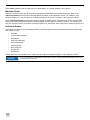
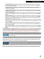
INPUT FORMAT Screen
The Input Format screen defines the contents and order of the batch information that will be supplied to Track &
Trace from a remote data source over Ethernet Channel 1, as configured in the COMMUNICATION screen.
Whenever a new input string is received by the vision system, Track & Trace will parse the information from the
input string and automatically set up the new batch.
-
Figure 3-18: INPUT FORMAT Screen
Input Fields
The input string can contain up to 8 different items of batch information. The following items are available:
•
Empty: The input field does not contain any data.
•
New Batch: Initiates a batch changeover and resets the batch statistics. The New Batch data must be
either 1 or 0. If 1, the batch statistics will be reset. If 0, batch statistics will not be reset. When New Batch is
selected, it must be the first item in the input string, or the batch information will not be processed correctly
and the inspection will fail.
•
OCV Line 1 … OCV Line 6: Sets the current match string contents for the specified OCV Line #. The OCV
Line must have its Data Source set to Ethernet.
•
ID Code 1 Match, ID Code 2 Match: Sets the Match Read Result for a non-GS1/sNDC ID code. In the
corresponding ID CODE (1 or 2) screen, the Data Format must be None and the Match Read Result must
be set to Ethernet.
•
ID Code GTIN: Sets the data string that will be matched against the read result of an ID code containing a
GS1 GTIN (01). One ID code must have its Match Read Result set to Ethernet and its Data Format set to
GS1.
•
ID Code Lot Number: Sets the data string that will be matched against the read result of an ID code
containing a GS1 lot/batch number (10). One ID code must have its Match Read Result set to Ethernet
and its Data Format set to GS1.
•
ID Code Production Date: Sets the data string that will be matched against the read result of an ID code
containing a GS1 Production Date (11). One ID code must have its Match Read Result set to Ethernet and
its Data Format set to GS1.
36
Setting Up Track & Trace
•
ID Code Best Before: Sets the data string that will be matched against the read result of an ID code
containing a GS1 Best Before date (15). One ID code must have its Match Read Result set to Ethernet
and its Data Format set to GS1.
•
ID Code Exp Date: Sets the data string that will be matched against the read result of an ID code
containing a GS1 Expiration Date (17). One ID code must have its Match Read Result set to Ethernet and
its Data Format set to GS1.
•
ID Code Serial Number: Sets the data string that will be matched against the read result of an ID code
containing a GS1 Serial Number (21). One ID code must have its Match Read Result set to Ethernet and
its Data Format set to GS1.
•
ID Code S/N Max Value: Sets the highest serial number value allowed. One ID code must have its Match
Read Result set to Ethernet, its Data Format set to GS1 and its Check Serial Number set to S/N Within
Range.
•
ID Code S/N Min Value: Sets the lowest serial number value allowed. One ID code must have its Match
Read Result set to Ethernet, its Data Format set to GS1 and its Check Serial Number set to S/N Within
Range. This item is available only when S/N Within Range is the selected Check Serial Number option in
the ID CODE 1 and/or ID CODE 2 screens.
•
ID Code Price: Sets the data string that will be matched against the read result of an ID code containing a
GS1 Price information (390n). One ID code must have its Match Read Result set to Ethernet and its Data
Format set to GS1.
•
sNDC - Serial Number: Sets the data string that will be matched against the read result of an ID code
containing a sNDC Serial Number. One ID code must have its Match Read Result set to Ethernet and its
Data Format set to sNDC.
•
sNDC - S/N Max Value: Sets the highest serial number value allowed. One ID code must have its Match
Read Result set to Ethernet, its Data Format set to sNDC and its Check Serial Number set to S/N Within
Range.
“Not Valid for Ethernet” is displayed to the right of input field selections that are invalid because Ethernet Channel
1 is not configured in the COMMUNICATIONS screen or because of incorrect settings in the ID CODE 1, ID CODE
2 or OCV LINES screens. If ERROR: One or more of the selected fields are not valid for Ethernet input is
displayed in the INPUT FORMAT screen, an invalid input field has been selected. Correct the settings in the
appropriate screens, then return to the INPUT FORMAT screen and select from among the valid input fields.
NOTE
The entire match string must be set to match the results of ID Code read. For example, if a GS1 Matrix
Code contains GTIN, Lot Number, Expiration Date and Serial Number, set the ID Code GTIN, ID Code
Lot Number, ID Code Exp Date and ID Code Serial Number. If only a part of the match string is set, the
inspection will fail.
Start, End and Separator Characters
Specify the ASCII decimal values for the starting, ending and separator characters that will included in the input
string received by Track & Trace. The character values you select will depend on the format of the data at the
output source, for example, your MES software or serialization database.
NOTE
A Separator Character is required when one or more variable length Data Items are selected. All Data
Item selections are variable length with the exception of ID Code GTIN and ID Code Expiration Date.
Input Format
The selected data items, including start character, field separator character and end character(s) are listed in the
parsing order of the input string. The actual data string received over Ethernet is displayed immediately below.
37
38
Operating Track & Trace
This chapter describes how to initiate a batch changeover using the Track & Trace user interface and how to
monitor Track & Trace operation during production.
CHANGE BATCH Screen
Figure 4-1: Track & Trace Main Menu
To initiate a new batch, click the Change Batch button on the main menu, which opens the CHANGE BATCH
screen.
Figure 4-2: CHANGE BATCH Screen
Enter New Batch Information
Before initiating a batch change, the information for the new batch must be supplied to Track & Trace.
Each item of batch information that must be typed in manually or that will be received remotely from an Ethernet
source is listed in the Data Item column. The yellow highlighted fields in the New Batch column indicate the batch
information that must be entered manually.
•
The fields in the top half of the screen are for entering the match strings for OCV lines, if the Data Source
for one or more OCV lines is set to Manual Entry in the OCV LINES screen.
•
The fields in the bottom half of the screen are used to enter the batch information that will be used to match
the read result of the ID code, if Match Read Result is set to Manual Entry in at least one of the ID CODE 1
or ID CODE 2 screens.
Click on each field to open the on-screen keyboard and enter/edit the new information. For reference, the typed in
information for the current batch is displayed in the Current Batch column.
NOTE
• Batch information items that will be supplied from a remote source over Ethernet are listed in the
Data Item column. However, the corresponding entry fields in the New Batch column will be disabled
because user input is not required.
• The entire match string must be entered to match the results of ID Code read. If only a part of the
match string is entered, the inspection will fail.
39
Change Batch
To manually initiate a batch change, click the CHANGE button. The Current Batch information will be updated, and
all of the inspection statistics will be reset to zero.
STATISTICS Screen
Track & Trace maintains statistics of all inspections performed for the current batch. To view the statistics for the
current batch, click the Statistics button on the main menu, which opens the STATISTICS screen.
Figure 4-3: STATISTICS Screen
Batch Statistics
The Batch Statistics display the overall pass/fail statistics for the current batch, and maintains a count of defects for
each of the OCV lines and ID codes that are enabled. Batch Statistics are reset to zero when a new batch is
initiated.
Operator Statistics
The Operator Statistics can be used to maintain a subset of statistics beginning from a particular point in time. For
example, a line supervisor might be interested in seeing the pass/fail statistics for all inspections performed while
they are logged on to Track & Trace. Click the Reset button to reset the Operator Statistics at any time; the Batch
Statistics are not affected.
40
Appendix A - Font Training
OCV/OCR Font Training Screen
This section provides instructions on how to train, view and modify a font using the OCV/OCR Font Training
screens.
• A maximum of eight instances of each character may be extracted to train each character model in
the font. By adding more character instances, you increase the variation tolerance of the
corresponding character model in the font.
NOTE
• A font may contain up to 255 character models, as well as 8 instances of a particular character; each
model is assigned a single-character label. When either of these limits is surpassed, the In-Sight
sensor will ignore any additional character models and they will not be added.
• An OCV/OCR application with little variation in character attributes from one image to the next may
require only one instance of each character to be extracted. The number of character instances
needed increases as greater tolerance to variations in character attributes is required.
Image Tab
The Image tab allows you to obtain images of the characters that you will use to train the font.
Figure A-1: Image Tab
If you already have an image of the characters to use for training the font, proceed to the Training Tab section.
Otherwise, to obtain an image of the characters:
1.
Click the Image button.
2.
Click the Live On button.
3.
Position the characters in the image and, if needed, adjust the lighting and focus.
4.
Click the Live Off button.
41
Training Tab
The Training tab allows characters to be extracted from an image to create models of each character.
Figure A-2: Training Tab
1.
To change the name of the font, click the Edit button. Edit the Font Name using the on-screen keyboard.
Click OK to accept the new name, or Cancel to undo the changes.
2.
Select the correct Polarity for the font. Click Dark on Light to train dark characters on a light background
or Light on Dark to train light characters on a dark background.
NOTE
3.
42
Ensure that you set the correct Polarity for your characters before adding characters to the font; Polarity
cannot be changed once character models have been added to the font.
By default, All Characters will be added to the font, even if instances of one or more of the characters
already exist in the font. Click New Characters if you want to add only new characters to the font.
Font Training
4.
Click the Add Characters button to access the font training controls.
Figure A-3: Add Characters
To train characters:
1.
Click the Edit button. Using the on-screen keyboard, enter the String that matches the first line of text
containing the characters you wish to train. Click OK to accept the String, or Cancel to undo the changes.
Figure A-4: Enter the String
NOTE
2.
When possible, do not add a single character to a trained font. Doing so eliminates spacing information,
which is important when reading the character in a string. If you do need to train a single character, you
must Modify the segment (as described in step 4 below), adjusting the width of the character box to
include space on each side of the character.
Click the Region button. Position and size the box so that it encloses the characters to be trained. Click
OK to accept the Region, or Cancel to undo the changes.
Figure A-5: Adjust the Region
3.
Click the Segment button. The characters in the Region will be separated into individual character
instances and assigned a label, based on the specified String that was entered.
Figure A-6: Segmented Characters
4.
If any of the characters have not been segmented correctly, click the Modify button. If needed, click the
Pan/Zoom button to pan or zoom the image. To adjust an incorrect segment, click on the segment Region
and adjust the size and position to surround the correct character. Repeat this step until all segments are
correctly positioned around the characters.
43
5.
If any of the characters are labeled incorrectly, verify that the String entered in step 1 matches the
characters in the image. Repeat step 1 to correct the String, if necessary. Alternately, click the Relabel
button, select a mislabeled character, click OK, and then enter the correct character label using the onscreen keyboard.
6.
If needed, click the Delete button to select an individual segment to delete, click OK, and then click Yes to
confirm.
7.
Once all characters are segmented and labeled correctly, click the Add To Font button. An instance of
each character in the selected line of text is added to the current font. Repeat these steps for each
additional line of text containing characters to be trained.
Figure A-7: Add Characters to the Font
8.
44
Click OK to return to the OCV/OCR Font Training screen.
Font Training
Font Tab
The Font tab is used to view and edit character models in a trained font. All characters, including spaces and
punctuation, are segmented and given character models. When a character model is selected in the Characters
list, the trained Instances for that model are also listed. The indicator adjacent to each character instance is
<character label>:<instance number>. For example, in Figure A-8, the second instance of character '0' is indicated
by '0:1' (instance numbering begins at zero).
Figure A-8: Font Tab
1.
The Enable checkbox specifies whether a character model is used in the font, and which instances of each
character are used to build the model. To disable a character model or character instance, highlight the
model or instance and uncheck the checkbox.
2.
If a character model or instance is incorrect, highlight the mislabeled model or instance and click the
Relabel button to correct the label. If a character model is selected, Relabel will change the name of every
instance for that model. If a single character instance is selected, then only that instance will be relabeled
and moved to the corresponding character model.
3.
To delete a character model, or individual instances from a character model, highlight the model or
instance and click the Delete button.
NOTE
4.
Deleting a character model will permanently delete all trained instances of that character.
Click the Edit button to view a close-up of the selected character model or instance in the Image Editor.
Character models can be edited; character instances can only be viewed.
45
Figure A-9: Edit a Character Model
To edit a character model:
1.
Click Black to edit white pixels, turning them black. Click White to edit black pixels, turning them white.
2.
Click the Pencil button.
3.
Click on pixel(s) in the font model to change their color. It is generally best to edit only those pixels in the
model that are obviously not part of the character. For example, in Figure A-9 there are two extraneous
pixels above the '0' that should be removed from the model by changing them from black to white. If
needed, click the Undo button to reverse the last action, and the Redo button to reapply the last action.
4.
Click OK to accept all edits to the character model; an asterisk (*) by the character model indicates that it
has been manually edited. Or, click Cancel to undo all edits that have been made to the character model
and return to the Font tab.
NOTE
Use the Image Editor sparingly. Better OCV results will be achieved by training the font using good
examples rather than editing poor examples.
5.
If you are unsatisfied with the manual edits made to the character model, select the model and click the
Rebuild button. All manual edits will be removed, and the character model will be restored to its original
state.
6.
To start over and remove all character models and instances from the font, click the Delete All button.
46
Font Training
Difference Table Tab
The Difference Table tab displays the difference of the scores for the two selected characters, comparing each
character model with all other models. The higher the score difference between two characters, the less likely that
those characters will be confused for one another during the OCV inspection. This data is useful because it
indicates any weaknesses in the trained font that could negatively impact performance.
In the example below, the score difference between the character models for '7' and '4' is significantly higher at 87,
which indicates that it is very unlikely that these two characters would ever be confused for the current font. At the
other extreme, the score difference between the character models for the '8' and the '5' is only 29. Thus, this
character pair is more vulnerable to confusion.
1.
Specify the Scoring Mode difference table to display (Speed or Accuracy). As mentioned previously, the
higher the difference score, the less likely the two selected characters will be confused as being the same
character during the inspection.
NOTE
In-Sight Track & Trace performs OCV using the Accuracy Reading Mode. Click the Accuracy button to
display the correct Difference Table for Track & Trace. If Speed is selected, the scores displayed in the
Difference Table will not be accurate.
Figure A-10: Difference Table Tab
2.
Specify a value from the Highlight Differences Value numeric control. All character model comparisons
scoring at or below the Differences Value will be highlighted, indicating which character model pairs are
most likely to be confused for one another. Click the up/down arrow buttons to increase or decrease the
threshold for highlighting score differences, or click the numbered button to type in the value using the onscreen keyboard. A warning indicates the number of character model comparisons scoring below the
Differences Value. In Figure A-10, the message "6 Warnings" is displayed because there are six character
model pairs in the font that score below the Differences Value.
Click on each highlighted pair to view the character models side-by-side. The Selected Characters field displays
the models of each character being compared. The comparison may reveal that the character models were not
47
trained correctly or that the character models were trained under poor imaging conditions or using low quality
characters.
NOTE
48
If a character has been disabled in the Font tab, no score will be displayed.
Appendix B - User Authentication
User Authentication
Before a user can log in to Track & Trace to configure batch settings, change a batch, or view batch statistics they
must exist as a user on every In-Sight vision system they will need to access. After a user has been created on the
vision system, their ability to interact with the Track & Trace user interface is determined by the Track & Trace user
permissions that have been defined for them.
Creating In-Sight Users
In-Sight users are created using In-Sight Explorer software. Each In-Sight vision system supports up to 16 users.
Every In-Sight user is assigned an Access Level:
•
Full access level users have complete, unrestricted access to the vision system, including the ability to
change system settings. Job files can be created, modified, loaded or saved, and all In-Sight Explorer
software selections are available. However, the ability of Full access level users to interact with the Track &
Trace user interface is determined by their Track & Trace user permissions. The default
In-Sight admin user account has Full access.
•
Protected access level users have limited access to the vision system, but without the ability to change
system settings. Protected access level users can switch to live video mode, toggle the Online/Offline
status of the vision system (if permitted by their Allow Online/Offline privileges) and open or save jobs (if
permitted by their FTP Read/Write privileges). The ability of Protected access level users to interact with
the Track & Trace user interface is determined by their Track & Trace User Permissions. The default InSight operator user account has Protected access.
•
Locked access level users can login to the vision system to monitor its operation, and have no ability to
change system settings or to interact with the Track & Trace user interface. The default In-Sight monitor
user account has Locked access.
Only In-Sight users with a Full or Protected access level can interact with the Track & Trace user interface,
regardless of their Track & Trace user permissions. In-Sight users with a Locked access level can log on to the
Track & Trace user interface to monitor its operation; however, all of the controls will be disabled. Except for
administrators who require access to vision system settings, most users who will log on to In-Sight through the
Track & Trace user interface should have a Protected access level.
NOTE
For instructions on creating and maintaining users on In-Sight vision systems, refer to the User List topic
in the In Sight® Explorer Help file.
49
Setting Track & Trace User Permissions
The Track & Trace job file supports three different types of users: Operator, Supervisor and Administrator. The
default user permissions in the Track & Trace job are most restrictive for an Operator, and most permissive for an
Administrator. However, the permissions for each type of user can be modified in the USER PERMISSIONS
screen.
Figure B-1: USER PERMISSIONS Screen
If you are installing Track & Trace for the first time and want to set user permissions, you can access the USER
PERMISSIONS screen from the HMI Display Control sample application installed with Track & Trace:
1.
Launch the Cognex HMI Display Control sample application from the Windows Start Menu and log on to a
vision system running a Track & Trace job.
2.
In the Sample Controls dialog, click Dialog in the Symbolic Tag list. Scroll down through the list and select
the UserPermissions tag.
3.
Click the Perform Action button. The USER PERMISSIONS screen will open in the HMI Display Control
sample application.
4.
For each type of user, check the box for each control that they will be able to access in the Track & Trace
user interface, and uncheck the box for each control that will be inaccessible. Controls that are unchecked
for a type of user will be grayed out for all users who log on with that user type.
5.
Click OK.
The HMI Display Control sample application can also be used to test the user permissions you define:
1.
Scroll down to the bottom of the Symbolic Tag list and click UserGp (User Group).
2.
Select the UserGroup tag then click the Set Value button. The default value is 2 (Administrator). Change
the value to 0 (Operator) or 1 (Supervisor) and click OK.
3.
If you changed the UserGroup tag value to 0, the Setup button on the Track & Trace main menu in the HMI
Display Control window will be grayed out and inaccessible. If you changed the UserGroup tag value to 1,
click the Setup button on the Track & Trace main menu, then click the ID CODE 1 button. Most of the
controls in the ID CODE 1 screen will be grayed out and inaccessible.
50
User Authentication
4.
Repeat steps 6 and 7, but this time change the UserGroup tag value back to 2 in order to restore access to
all controls in the Track & Trace user interface.
NOTE
• In order to apply Track & Trace user permissions, the UserGroup symbolic tag must be set
programmatically whenever a user logs in to the Track & Trace interface from your custom
application. Refer to the Examples section on page 67 for more information.
• The USER PERMISSIONS screen is designed to be accessed programmatically using the HMI
Display Control. Refer to the Examples section on page 67 for information on how to open the USER
PERMISSIONS screen from your custom application
Idle Timeout
To prevent unauthorized users from changing Track & Trace settings, a timeout can be set to automatically log the
previous user off of the vision system after a period of inactivity. If a user is automatically logged out, the next user
to log on must enter their user name and password in order to access Track & Trace. The steps to set the idle
timeout differ, depending on which user interface is used to log on to an In-Sight vision system running Track &
Trace.
See the VisionView® Software Manual for details on how to set the idle timeout for the VisionView Operator
Interface Panel or the VisionView PC software.
To set the idle timeout for the HMI Display Control in your application, refer to Appendix D - Integrating the HMI
Display Control on page 63.
NOTE
When using In-Sight Explorer to log on to the vision system running a Track & Trace job, no idle timeout
is available.
51
52
Appendix C - Creating an Audit Trail
Creating an Audit Trail
In-Sight Track & Trace supports FDA 21 CFR Part 11 validation with the ability to automatically generate timestamped audit messages that can be archived in your audit trail log file or compliance database. Audit messages
are supported for the following types of activity:
•
In-Sight system events, such as startup, user logon and logoff, switching into Online and Offline operation
and job changes.
•
Changes to In-Sight system settings.
•
Changes to settings in a Track & Trace job, and batch changes.
Creating an audit trail for your In-Sight Track & Trace installations requires four steps:
1.
Install and configure an audit message server on a PC. An audit message server “listens” for audit
messages sent from one or more vision systems on the network. Cognex provides sample code for
developers to create an audit message server when audit messages need to be recorded in a compliance
database or written to an audit trail log file. Track & Trace also includes the Cognex Audit Message Demo,
which writes audit messages in XML format to a plain text log file.
2.
Configure Audit Message Settings on your In-Sight vision systems.
3.
Connect to the audit message server from your database or logging application to collect audit messages
received from In-Sight vision systems.
4.
Import audit messages into your compliance database or audit trail log file.
The remainder of this section provides setup instructions, audit message specifications, and audit message server
sample code for creating an audit trail for In-Sight Track & Trace vision systems.
NOTE
When using the Cognex Audit Message Demo application or the Cognex Audit Message Server Sample
application on the Windows 7 operating system, if the User Account Control (UAC) settings are not
disabled, run the application as an administrator.
Configure the Cognex Audit Message Demo Application
See Sample Code – Visual Studio .NET C# 2008 on page 56 if you will create your own audit message server. But
first, it is recommended that you configure the Cognex Audit Message Demo to see how audit messaging works.
• The Cognex Audit Message Demo application included in the Track & Trace installer is for
demonstration and test purposes and not intended for deployment.
NOTE
• If Track & Trace 1.0.0 is already installed on your PC, you must uninstall the Cognex Audit Message
Service from your PC using the system tray uninstall option before using the Cognex Audit Message
Demo application.
53
1.
Launch the Cognex Audit Message Demo from the Windows Start menu (the default location is
Programs\Cognex\In-Sight\In-Sight Track & Trace 1.0.1\).
Figure C-1: Cognex Audit Message Demo Application
2.
The Server Address is the IP address of the PC. If more than one network IP address is available on the
PC, you can select a different IP address for the Audit Message Server. Click the Select button to see the
IP addresses that are available on the PC, and select the IP address for the Audit Message Server from
the list.
3.
Check the Use local time for message box to time stamp audit messages with the date and time of the
PC. This ensures that all audit messages received from In-Sight vision systems on the network will have a
correct time stamp even if those vision systems are not configured to use an SNTP server, or the SNTP
server becomes unavailable.
4.
Click the Add button to open the Add Audit Message Port dialog. Enter an unused TCP/IP port between
1024 and 65535 (the default is 5753). This is the port at which your database or audit trail logging software
will connect in order to collect audit messages from In-Sight vision systems. Multiple vision systems can
send messages to the same Audit Message Port, or multiple Audit Message Ports can be added, one for
each vision system that has been configured for audit messaging.
Figure C-2: Add Audit Message Port
NOTE
5.
54
The following TCP/IP ports are within the allowed range, but they are reserved by In-Sight and can not
be entered: 1069 (In-Sight Protocol), 1070 (Machine Status data), 1212 (Upgrade port), 2222 and 44818
(EtherNet/IP), and 50000 (DataChannel).
Check the Log to File box. At the prompt, enter a filename for the log file (with .txt or .log file extension). If
you added multiple TCP/IP ports in the previous step, create a log file for each port.
Creating an Audit Trail
Configure In-Sight Audit Message Settings
Before an In-Sight vision system running Track & Trace can generate and send audit messages, the vision
system’s Audit Messaging Settings must be configured in In-Sight Explorer.
1.
Open In-Sight Explorer and log on to a vision system running a Track & Trace job.
2.
From the Sensor menu, select Audit Message Settings.
Figure C-3: In-Sight Audit Message Settings dialog
3.
Check Enable Audit Messages to turn audit messaging on for this vision system.
4.
For the Server Address, enter the IP address of the PC running the audit message server, and the Server
Port number. If you are using the Cognex Audit Message Demo, enter the IP Address and the Audit
Message Port you configured in the previous section.
5.
Select the message types for which this vision system will generate audit messages:
• System Events
• Changes to Tagged Cells
• Changes to System Settings
6.
Click OK to close the Audit Message Settings dialog.
55
7.
If you have correctly configured the Audit Message Server and the vision system’s Audit Message
Settings, the first audit message will be displayed in the Audit Message Demo application.
Figure C-4: Cognex Audit Message Demo, first audit message
Notice that In-Sight sends audit messages in XML format, which is described in Audit Message Format on page 58.
Sample Code – Visual Studio .NET C# 2008
The Cognex Audit Message Demo application is fully functional, but you will want to integrate an audit message
server into your own application.
Track & Trace includes the source code for a basic audit message server. This sample logs audit messages to a
file, but you can modify it as needed to collect audit messages and convert the XML data for your compliance
database or audit trail logging system.
56
Creating an Audit Trail
// Sample Audit Message Server Application
using System;
using System.IO;
// Make sure to add a reference in your project to "Cognex.AuditMsg.dll"
using Cognex.AuditMsg;
public class SampleAuditMessageServerApplication
{
/// <summary>
/// This console application shows how to use the Cognex Audit Message Server.
/// </summary>
/// <remarks>
/// The messages received from devices will be displayed to the Console window as well
/// as written to a file that is saved on exit.
/// </remarks>
public static void Main()
{
// Create file for logging audit messages
_logFile = new FileStream(@"C:\logFile.txt", FileMode.Create, FileAccess.ReadWrite);
_logWriter = new StreamWriter(_logFile);
// Setup the server on port number 5753
AuditMsgServer auditMsgServer = new AuditMsgServer(5753);
// Handle audit messages that are received
auditMsgServer.MessageReceived += new AuditMessageEventHandler(AuditMessageReceived);
// Start the server, allowing it to receive audit messages
try
{
auditMsgServer.Start();
} catch (Exception ex) { Console.WriteLine("Server failed to start: " + ex.Message); }
if (auditMsgServer.IsRunning)
{
Console.WriteLine("Audit Message Server\n");
Console.WriteLine("
Listening on {0}:{1}", auditMsgServer.Address, auditMsgServer.Port);
Console.WriteLine("\nWaiting for a connection.....\nPress any Key to abort\n");
Console.ReadKey();
}
// Stop the server, preventing it from receiving audit messages
auditMsgServer.Stop();
// Close the log file
_logWriter.Close();
_logFile.Close();
}
// Dispose of all resources used by the server
auditMsgServer.Dispose();
/// <summary>The log file that saves the audit messages,</summary>
private static FileStream _logFile;
/// <summary>The writer used for writing audit messages to the log file.</summary>
private static StreamWriter _logWriter;
}
/// <summary>
/// Handles the processing of an audit message received from a device.
/// </summary>
/// <param name="sender">The server instance that sent the message.</param>
/// <param name="args">The audit message.</param>
/// <remarks>
/// NOTE: This method is called on a thread pool thread in a console application.
///
In a windowed application, this will be called on the GUI thread.
/// </remarks>
static void AuditMessageReceived(object sender, AuditMessageEventArgs args)
{
_logWriter.Write(args.AuditMessageXml);
Console.WriteLine(args.AuditMessageXml);
}
57
Audit Message Format
In-Sight audit messages are in XML format, which provides maximum flexibility for converting the data into records
for your compliance database or entries in your audit trail log file.
Audit Message Header
All Audit Messages are preceded by an XML declaration, containing the date and time; the name of the currently
logged on user; the Host Name of the vision system; the name of the PC (or VisionView Operator Interface Panel)
from which the action was initiated; and a message ID. This information is relayed in the attributes of the XML
<AuditMessage> tag.
<?xml version="1.0" encoding="UTF-8"?>
<AuditMessage date="2009-08-17" time="10:54:47-07:00" user="admin" system="ism1400_010203"
connection="PC1" id="3">
</AuditMessage>
XML Declaration
The Audit Message includes an XML declaration to indicate the formatting of the message as UTF-8.
Example: <?xml version="1.0" encoding="UTF-8"?>
Date
The date attribute follows the ISO 8601 calendar date format: YYYY-MM-DD.
Example: date="2009-08-17"
Time
The time attribute follows the ISO 8601 time format: hh:mm:ss±hh:mm.
Example: time="10:54:47-07:00"
User
The user attribute is a string containing the user name that is currently logged on to the vision system. If no user is
currently logged on, an empty string "" is returned.
Example: user="admin"
System
The system attribute is a string containing the vision system host name.
Example: system="ism1400_010203"
Connection
The connection attribute is a string containing a description of the connection to the vision system. If no connection
is established – during startup, for example – an empty string "" is returned.
Typically, the string is the host name of the PC or VisionView Operator Interface Panel through which the user is
logged on to the vision system. There are two exceptions:
•
NativeMode: Indicates the message was generated as a result of a Native Mode command using telnet to
port 23.
•
DiscreteInput: Indicates the message was generated as a result of a signal on the hardware input lines
(either serial or internal).
Examples:
connection="NativeMode"
connection="DiscreteInput"
connection="PC17689"
connection=""
58
Creating an Audit Trail
ID
The ID attribute is a non-zero positive integer indicating the sequence number of the Audit Message from a
particular vision system. This number starts at 1 when the vision system starts up, and increments with each
message sent. When combined with the Date, Time and System attributes, every audit message sent can be
uniquely identified.
NOTE
IDs can be repeated in messages from different vision systems or when a vision system is restarted.
Example: id="3"
Event Messages
Types of Events
If an In-Sight system event occurs (logging on or off of a vision system, loading or saving a job file, transitioning
from Online to Offline mode, system startup or firmware update), an event message type is generated. Certain
events (start up, load job, save job, failed logon attempt and firmware update) convey additional information, with
<value> tags surrounding the additional data.
NOTE
In-Sight firmware version 4.4.1 and higher generates audit messages for failed logon attempts.
When a logon attempt fails, the following information is displayed within <value> tag:
•
Invalid Password: The password entered is incorrect.
•
Invalid Username: The User Name entered does not exist in the User List.
•
System Locked: The vision system is locked by another user. This information is usually displayed when
a firmware update is in process.
•
Access Not Permitted For User: The user is not authorized access to the vision system.
•
Spreadsheet View Access Not Permitted: The user does not have access to the Spreadsheet View on
the vision system. This information is usually displayed when the user has access to the EasyBuilder View.
•
Unspecified Failure: The logon attempt is unsuccessful for unknown reasons.
NOTE
For ore information on user names, passwords and access levels, see the "User List Dialog" topic in the
In-Sight® Explorer Help File.
XML Format of Event Messages:
<?xml version="1.0" encoding="UTF-8"?>
<AuditMessage date="2009-09-01" time="10:36:55-07:00" user="admin" system="ism1400_010203"
connection="PC1" id="8">
<event type="LogOn" success="true" />
</AuditMessage>
<?xml version="1.0" encoding="UTF-8"?>
<AuditMessage date="2009-09-01" time="10:36:55-07:00" user="admin" system="ism1400_010203"
connection="PC1" id="11">
<event type="LogOn" success="false">
<value>Invalid Password</value>
</event>
</AuditMessage>
<?xml version="1.0" encoding="UTF-8"?>
<AuditMessage date="2009-09-01" time="11:34:53-07:00" user="" system="ism1400_010203"
connection="" id="1">
<event type="StartUp" success="true" />
<value>4.04.01 Beta (045)</value>
</event>
</AuditMessage>
59
Change Messages
If a change occurs (to In-Sight system settings, or tagged cells in the job spreadsheet), a change message is
generated. A single XML format is used to communicate these various types of changes.
System change
If a system setting (any setting stored in the In-Sight vision system’s proc.set file) is modified, a system message is
generated. The Audit Message includes the name of the setting that was changed, and the new value.
Example:
<?xml version="1.0" encoding="UTF-8"?>
<AuditMessage date="2009-09-01" time="14:52:48-07:00" user="admin" system=“ism1400_010203”
connection="PC1" id="6">
<change type="system" name="TimeService">
<newValue>Pacific Standard Time</newValue>
</change>
</AuditMessage>
Data or Formula Change
If a cell in a job spreadsheet has been assigned an Audit Message Symbolic Tag, and that cell is edited (e.g.,
changes are made to the cell's formula, or the user changes the value of an interactive control), a data or formula
message is generated; both the old and new values are included in the message.
Example Data Change:
<?xml version="1.0" encoding="UTF-8"?>
<AuditMessage date="2009-09-01" time="14:52:48-07:00" user="admin" system=“ism1400_010203”
connection="PC1" id="6">
<change type="data" name="FruitListBox">
<newValue>0, apple</newValue>
<oldValue>1, orange</oldValue>
</change>
</AuditMessage>
Example Formula Change:
<?xml version="1.0" encoding="UTF-8"?>
<AuditMessage date="2009-09-01" time="14:52:48-07:00" user="admin" system=“ism1400_010203”
connection="PC1" id="6">
<change type="formula" name="FruitListBox">
<newValue>ListBox("apple", "orange", "banana", "grape")</newValue>
<oldValue>ListBox("apple", "orange", "banana")</oldValue>
</change>
</AuditMessage>
60
Creating an Audit Trail
Schema for Audit Messages
<?xml version="1.0" encoding="UTF-8"?>
<xs:schema id="CognexAuditMessage" xmlns:xs="http://www.w3.org/2001/XMLSchema">
<xs:element name="AuditMessage">
<xs:complexType>
<xs:sequence>
<xs:element name="change" minOccurs="0" maxOccurs="1">
<xs:complexType>
<xs:sequence>
<xs:element name="newValue" type="xs:string" minOccurs="0" maxOccurs="1"/>
<xs:element name="oldValue" type="xs:string" minOccurs="0" maxOccurs="1"/>
</xs:sequence>
<xs:attribute name="type" type="xs:string" use="required" />
<xs:attribute name="name" type="xs:string" use="required" />
</xs:complexType>
</xs:element>
<xs:element name="event" minOccurs="0" maxOccurs="1">
<xs:complexType>
<xs:sequence>
<xs:element name="value" type="xs:string" minOccurs="0" maxOccurs="1"/>
</xs:sequence>
<xs:attribute name="type" type="xs:string" use="required" />
<xs:attribute name="success" type="xs:boolean" />
</xs:complexType>
</xs:element>
</xs:sequence>
<xs:attribute name="date" type="xs:date" use="required" />
<xs:attribute name="time" type="xs:time" use="required" />
<xs:attribute name="user" type="xs:string" use="required" />
<xs:attribute name="system" type="xs:string" use="required" />
<xs:attribute name="connection" type="xs:string" use="required" />
<xs:attribute name="id" type="xs:positiveInteger" use="required" />
</xs:complexType>
</xs:element>
</xs:schema>
61
62
Appendix D - Integrating the HMI Display Control
Integrating the HMI Display Control
The Cognex HMI Display Control (CnxHmiDisplay) is a .NET control that allows developers to seamlessly integrate
the In-Sight Track & Trace user interface into a custom application. For example, the Track & Trace interface can
be integrated into an HMI that also hosts the user interfaces to other devices on the same packaging line such as a
printer or a weigh station.
The “touch screen” friendly, look-and-feel of the HMI Display Control is similar to that of the Cognex VisionView
Operator Interface Panel. Interactive graphical elements in the HMI Display Control provide easy access to
essential functionality for interacting with the vision system, such as adjusting the image or switching the vision
system Online and Offline. By simply dropping the HMI Display Control into a .NET application and setting a few
properties, users have the power to view and interact with Track & Trace from within the context of your custom
application.
Figure D-1: Cognex HMI Display Control Sample Application
The HMI Display Control provides a rich API to access various Track & Trace and In-Sight vision system features
and functions. To help you get started, use the Cognex HMI Display Control Sample application to understand how
to integrate Track & Trace into your own application.
63
HMI Display Control Prerequisites
The following are requirements for use of the Cognex HMI Display Control:
•
Visual Studio 2008:
•
VB.NET or C# programming experience
•
Cognex Track & Trace software installation
Adding the HMI Display Control to your Application
When you install In-Sight Track & Trace, a sample HMI application is also loaded as shown in Figure D-1. This
section describes the steps necessary to develop a new application that consumes the HMI Display Control.
1.
Start Microsoft Visual Studio and create a new Windows Application project.
Figure D-2: New Project Dialog
2.
If it is not already visible, open the Toolbox (View menu > Toolbox). In the Cognex In-Sight Components
tab, right-click Choose Items….
Figure D-3: Toolbox
64
Integrating the HMI Display Control
3.
In the Choose Toolbox Items dialog locate the CnxHmiDisplay component in the .NET Framework
Components tab and make sure it is checked.
NOTE
If the CnxHmiDisplay component is missing from the list of components, it can also be manually located
by selecting Browse… then navigating to the Track & Trace installation folder and selecting the
Cognex.Cnx.Components.dll assembly (by default the installation folder is C:\Program Files\Cognex\
In-Sight\In-Sight Track & Trace 1.0.0\Cognex HMI Control).
Figure D-4: Choose Toolbox Items
Once added to the Toolbox, the CnxHmiDisplay component can then be inserted into the application’s
form.
4.
Adding the CnxHmiDisplay to the form automatically adds several required references to the project,
specifically:
• Cognex.Cnx.Controls
• Cognex.Cnx.Components
• Cognex.Cnx.Core
• Cognex.Cnx.Framework
There are two additional references that need to be added. Under the Project menu, select Add
Reference….
Figure D-5: Add Reference Dialog
65
You will need to locate and select the following two references:
• Cognex.Cnx.InSight
• Cognex.InSight
Using the HMI Display Control – Properties
The HMI Display Control can be used in a mode that emulates the VisionView Operator Interface Panel. No
programming is required in this configuration. The connection and the appearance of the HMI Display Control can
be configured simply using the control’s properties. The following properties are available through the Properties
pane when the HMI Display Control is selected:
•
AutoConnectString: Allows connection to an In-Sight vision system running a Track & Trace job file. The
format of the string is either “IP,username,password” (without the quotes) or “IP,username” if no password
is required. For example, “192.168.0.1,admin” will allow connection to a vision system located at IP
address 192.168.0.1 that has a user named admin and no password.
NOTE
A successful connection requires that a valid Track & Trace job is loaded on the target In-Sight vision
system. If a valid Track & Trace job is not loaded there will be no error, but the control will not connect.
•
LiveImageQuality: Configures the sub-sampling (if any) of the live video image.
•
OnlineImageQuality: Configures the sub-sampling (if any) of the inspected image.
•
OperatorControls: Determines which user interface components are displayed.
•
ShowFilmstrip: Determines if the image history filmstrip is displayed.
•
ShowStatusPanel: Determines if the status panel is displayed.
NOTE
•
It is highly recommended that ShowStatusPanel be set to True to determine if a connection to an
In-Sight vision system has been established.
StatusLevelStyle: Sets the visual style of the status panel widgets.
These properties can be accessed directly in the control’s property sheet. The usage of these properties is defined
in the CnxHmiDisplay class reference.
Programming the HMI Display Control
In addition to the properties available in the HMI Display Control property sheet, the control has additional
properties and methods that can be accessed programmatically. In order to fully make use of these members,
access to additional classes is needed. All of these classes are defined in the Cognex.Cnx.Components assembly.
These classes can be accessed using a fully qualified path, or by simply importing the Cognex.Cnx.Components
namespace by placing the following statement at the top of the form code:
For VB.NET
Imports Cognex.Cnx.Components
For C#
using Cognex.Cnx.Components
The methods and properties of the HMI Display Control are listed in the Cognex HMI Display Control Reference
help documentation. Example usages of these members are provided below; consult the documentation for further
information.
66
Integrating the HMI Display Control
Examples
The following examples assume a control has already been added with the default name CnxHmiDisplay1.
Manually establishing a connection to a Track & Trace vision system at IP address 192.168.1.1
CnxHmiDisplay1.Connect("192.168.1.1, admin")
Determine if the Track & Trace vision system has a valid job loaded
bIsValid = CnxHmiDisplay1.IsValidJob
Setting the idle time (in minutes) before an operator user is logged out (default is 10 minutes)
CnxHmiDisplay1.IdleTimeout = iTimeout
The timeout can be disabled by specifying a value of zero.
NOTE
Retrieving the name of an available display view
myBrowseName = CnxHmiDisplay1.AvailableViews(index).BrowseName
Switching to a display view by name
CnxHmiDisplay1.SelectView(myBrowseName)
Services
As noted previously, the Track & Trace job and In-Sight vision system are independent of the HMI Display Control.
Services provide a way for the HMI Display Control to access the job and vision system to perform job-related
actions such as changing jobs and job configuration. The services that are available are provided as members of
the display control, and include:
·
ChangeJobService
(for accessing Track & Trace jobs)
·
LiveAcquisitionService
(for setting a vision system’s live video mode)
·
OnlineOfflineService
(for setting a vision system’s in/out inspection mode)
·
ResultsService
(for retrieving or modifying job parameters)
·
TrainFontScreenService
(for training the OCV font)
For example:
Retrieving available jobs from a connected Track & Trace vision system
myJobNames = CnxHmiDisplay1.ChangeJobService.GetJobNames()
Setting the current Track & Trace vision system job (not as the startup job)
CnxHmiDisplay1.ChangeJobService.ChangeJob(myJobName, False)
Symbolic Tags
Services also provide the ability to retrieve and modify values in the job, as well as to display various dialog boxes
that enable advanced configuration. This level of access is gained through the use of tags along with the services.
Tags identify the specific items within the job. The following are two code examples of accessing and using tags to
perform actions:
Retrieving symbolic tags available in a Track & Trace job
(collection of Cognex.Cnx.ComponentModel.CnxTaggedResultMetadata)
myTags = CnxHmiDisplay1.ResultsService.SymbolicTags()
Retrieving a value corresponding to a symbolic tag
CnxHmiDisplay1.ResultsService.GetValue(myTag.BrowseName)
67
Setting the value corresponding to a symbolic tag
CnxHmiDisplay1.ResultsService.SetValue(myTag.BrowseName, valueString)
Changing user access level using the UserGP.UserGroup tag
cnxHmiDisplay1.ResultsService.SetValue("UserGP.UserGroup", iLevel)
where iLevel can have the following values:
0 (Operator)
1 (Supervisor)
2 (Administrator)
Displaying a dialog to modify user access permissions using the Dialog.UserPermissions tag
cnxHmiDisplay1.ResultsService.PerformAction("Dialog.UserPermissions”)
A list of the most useful symbolic tags in a Track & Trace job, along with their related services (either the
ResultsService or the TrainFontScreenService) are provided below. To see all of the symbolic tags available in the
Track & Trace job, refer to the Symbolic Tag list in the HMI Display Control Sample application.
Table D-1: Track & Trace Symbolic Tag Names (Single Unit Job)
Tag
Description
Required Service and Method
Job Information
JobVersion
Gets the job version information.
ResultsService.GetValue()
Stat.Batch.Total
Gets the actual batch statistic: count of total
parts.
ResultsService.GetValue()
Stat.Batch.Good
Gets the actual batch statistic: count of passed
parts.
ResultsService.GetValue()
Stat.Batch.Bad
Gets the actual batch statistic: count of failed
parts.
ResultsService.GetValue()
Stat.Batch.Defect.OcvLine1
Gets the actual batch statistic: count of defects
for OCV line 1…6.
ResultsService.GetValue()
Stat.Batch.Defect.Pattern
Gets the actual batch statistic: count of defects
for pattern search.
ResultsService.GetValue()
Stat.Batch.Defect.Code1
Gets the actual batch statistic: count of defects
for ID code 1…2.
ResultsService.GetValue()
Stat.Operator.Total
Gets the actual operator statistic: count of total
parts.
ResultsService.GetValue()
Stat.Operator.Good
Gets the actual operator statistic: count of
passed parts.
ResultsService.GetValue()
Stat.Operator.Bad\
Gets the actual operator statistic: count of failed ResultsService.GetValue()
parts.
Stat.Operator.Defect.OcvLine1
Gets the actual operator statistic: count of
defects for OCV line 1…6.
Batch Statistics
Stat.Batch.Defect.OcvLine2
Stat.Batch.Defect.OcvLine3
Stat.Batch.Defect.OcvLine4
Stat.Batch.Defect.OcvLine5
Stat.Batch.Defect.OcvLine6
Stat.Batch.Defect.Code2
Operator Statistics
Stat.Operator.Defect.OcvLine2
Stat.Operator.Defect.OcvLine3
Stat.Operator.Defect.OcvLine4
Stat.Operator.Defect.OcvLine5
Stat.Operator.Defect.OcvLine6
68
ResultsService.GetValue()
Integrating the HMI Display Control
Table D-1: Track & Trace Symbolic Tag Names (Single Unit Job) (Cont.)
Tag
Description
Required Service and Method
Stat.Operator.Defect.Pattern
Gets the actual operator statistic: count of
defects for pattern search.
ResultsService.GetValue()
Stat.Operator.Defect.Code1
Gets the actual operator statistic: count of
defects for ID code 1…2.
ResultsService.GetValue()
Stat.Operator.Defect.Code2
Stat.Operator.Reset
Reset the actual operator statistic.
ResultsService.PerformAction()
Gets the actual batch information for OCV line
1…6.
ResultsService.GetValue()
Gets the actual batch information for ID code 1
field 1…5 to compare with the GS1 data.
ResultsService.GetValue()
Batch Information (current batch)
BatchInfo.OcvLine1.ActualString
BatchInfo.OcvLine2.ActualString
BatchInfo.OcvLine3.ActualString
BatchInfo.OcvLine4.ActualString
BatchInfo.OcvLine5.ActualString
BatchInfo.OcvLine6.ActualString
BatchInfo.IDCode1Field1.ActualString
BatchInfo.IDCode1Field2.ActualString
BatchInfo.IDCode1Field3.ActualString
BatchInfo.IDCode1Field4.ActualString
BatchInfo.IDCode1Field5.ActualString
BatchInfo.IDCode2.ActualString
Gets the actual batch information for ID code 2. ResultsService.GetValue()
Batch Information (new batch)
BatchInfo.OcvLine1.NewString
BatchInfo.OcvLine2.NewString
Sets the new batch information for OCV line
1…6
ResultsService.SetValue()
Sets the new batch information for ID code 1
field 1…5 to compare with the GS1 data.
ResultsService.SetValue()
Sets the new batch information for ID code 2 to
compare with the encoded data.
ResultsService.SetValue()
BatchInfo.OcvLine3.NewString
BatchInfo.OcvLine4.NewString
BatchInfo.OcvLine5.NewString
BatchInfo.OcvLine6.NewString
BatchInfo.IDCode1Field1.NewString
BatchInfo.IDCode1Field2.NewString
BatchInfo.IDCode1Field3.NewString
BatchInfo.IDCode1Field4.NewString
BatchInfo.IDCode1Field5.NewString
BatchInfo.IDCode2.NewString
Batch Information (names)
BatchInfo.OcvLine1.Name
BatchInfo.OcvLine2.Name
BatchInfo.OcvLine3.Name
Gets the name of OCV line 1…6 describing data ResultsService.GetValue()
printed on that line. For example “GTIN”, “Expiry
Date” or “Lot Number”.
BatchInfo.OcvLine4.Name
BatchInfo.OcvLine5.Name
BatchInfo.OcvLine6.Name
BatchInfo.IDCode1Field1.Name
BatchInfo.IDCode1Field2.Name
Gets the name of field 1…5 of code 1. For
ResultsService.GetValue()
example “GTIN”, “Expiry Date” or “Lot Number”.
BatchInfo.IDCode1Field3.Name
BatchInfo.IDCode1Field4.Name
BatchInfo.IDCode1Field5.Name
BatchInfo.IDCode2.Name
Gets the name of ID code 2.
ResultsService.GetValue()
69
Table D-1: Track & Trace Symbolic Tag Names (Single Unit Job) (Cont.)
Tag
Description
Required Service and Method
Batch Information (flags)
BatchInfo.OcvLine1.Valid
BatchInfo.OcvLine2.Valid
Gets a flag indicating that OCV line 1…6 is used. ResultsService.GetValue()
Returns “True” or “False”.
BatchInfo.OcvLine3.Valid
BatchInfo.OcvLine4.Valid
BatchInfo.OcvLine5.Valid
BatchInfo.OcvLine6.Valid
BatchInfo.IDCode1Field1.Valid
BatchInfo.IDCode1Field2.Valid
BatchInfo.IDCode1Field3.Valid
Gets a flag indicating that field 1…5 for code 1 is ResultsService.GetValue()
used to compare with the GS1 data. Returns
“True” or “False”.
BatchInfo.IDCode1Field4.Valid
BatchInfo.IDCode1Field5.Valid
BatchInfo.IDCode2.Valid
Gets a flag indicating that ID code 2 is used.
Returns “True” or “False”.
ResultsService.GetValue()
Accesses the “Change” button that applies and
activates any new batch information.
ResultsService.PerformAction()
Batch Information (buttons)
BatchInfo.ChangeBatch
Dialog Boxes
Dialog.Statistics
Opens the “Statistics” dialog box.
ResultsService.PerformAction()
Dialog.Batch
Opens the BATCH screen.
ResultsService.PerformAction()
Dialog.ImageSettings
Opens the IMAGE SETTINGS screen.
ResultsService.PerformAction()
Dialog.LocationTools
Opens the LOCATION TOOLS screen to
configure the PatMax or PatFind search tool.
ResultsService.PerformAction()
Dialog.IDCode1
Opens the ID CODE 1 screen.
ResultsService.PerformAction()
Dialog.IDCode2
Opens the ID CODE 2 screen.
ResultsService.PerformAction()
Dialog.OcvLines
Opens the OCV LINES screen.
ResultsService.PerformAction()
Dialog.Display
Opens the ON-SCREEN DISPLAY screen.
ResultsService.PerformAction()
Dialog.Communication
Opens the COMMUNICATION screen.
ResultsService.PerformAction()
Dialog.InputFormat
Opens the INPUT FORMAT screen.
ResultsService.PerformAction()
Dialog.OutputFormat
Opens the OUTPUT FORMAT screen.
ResultsService.PerformAction()
Dialog.DateFormat
Opens the DATE FORMAT screen.
ResultsService.PerformAction()
Dialog.TrainFonts
Opens the TRAIN FONTS screen.
ResultsService.PerformAction()
Dialog.UserPermissions
Opens the USER PERMISSIONS screen.
ResultsService.PerformAction()
Opens the OCV/OCR Font Training screen for
font 1…4.
TrainFontScreenService.ShowScreen()
Localized.SelectedLanguage
Gets and sets the index of the selected
language. Valid values are 0, 1 and 2.
ResultsService.GetValue() and
ResultsService.SetValue()
Localized.LanguageName1
Gets the name of language 1…3.
ResultsService.GetValue()
Font Training
Font.Dialog.TrainFont1
Font.Dialog.TrainFont2
Font.Dialog.TrainFont3
Font.Dialog.TrainFont4
Localization
Localized.LanguageName2
Localized.LanguageName3
Localization
UserGP.UserName
Gets the name of the current user.
ResultsService.GetValue()
UserGP.UserGroup
Gets and sets current user access level. Valid
values are 0, 1 and 2.
ResultsService.GetValue() and
ResultsService.SetValue()
70
Integrating the HMI Display Control
Language Localization
As noted in at the beginning of this section, the HMI Display Control and the Track & Trace job are distinct and
independent. Consequently, modifying the language in one does not affect the language in the other; both the HMI
Display Control and the Track & Trace job need to be localized, as required.
Changing the language used for the HMI Display Control (but not the Track & Trace job) is performed using the
following sequence:
Cognex.Cnx.CnxApplication.Culture = CnxHmiDisplay.InstalledCultures(i)
cnxHmiDisplay1.Refresh()
Changing the language in the job requires the use of the Result service and the Localized group of tags.
Specifically:
cnxHmiDisplay1.ResultsService.SetValue("Localized.SelectLanguage”, iLang)
where iLang can have the value of 0, 1, or 2
The default set of languages that are included in the Track & Trace job are English (0), French (1), and German (2).
It is possible to modify these and localize for a different set of three languages. If this is necessary, please contact
your local Cognex representative for assistance.
71
System
DISTRIBUTEUR CONSEIL DEPUIS 1985
72
2 rue René Laennec 51500 Taissy France
Fax: 03 26 85 19 08, Tel : 03 26 82 49 29
Email: [email protected]
Site web : www.hvssystem.com
P/N 597-0050-02