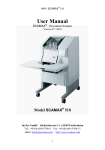
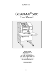
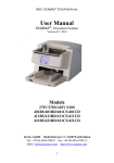
Download SCAMAX - InoTec
Transcript
Technical Manual Document Scanner SCAMAX ® H04 Issued 31.01.2013 (TW) SCAMAX®H04 Technical Manual 1/2012 1 Table of Contents Technical Manual 1 Technical Data and Safety Notices.................................................................................................... 3 1.1 TECHNICAL DATA ............................................................................................................................. 3 1.2 SAFETY NOTICES ............................................................................................................................. 3 2 SYSTEM STRUCTURE ........................................................................................................................ 4 3 SCANNER STRUCTURE AND PRINCIPAL OF OPERATION ........................................................... 5 3.1 OPENING COVERS ............................................................................................................................ 7 3.2 PAPER TRANSPORT .......................................................................................................................... 8 3.2.1 Input Hopper Table (Hopper) with Hopper Motor ................................................................... 8 3.2.2 Paper Feeder ........................................................................................................................ 10 3.2.2.1 Adjusting the Paper Feeder ............................................................................................................. 12 3.2.3 Paper Guide .......................................................................................................................... 14 3.2.4 Paper Transport Rollers and Bearings ................................................................................. 14 3.2.5 Paper Ejection Path .............................................................................................................. 16 3.2.6 Output Hopper ...................................................................................................................... 17 3.2.7 Paper Former ........................................................................................................................ 18 3.2.8 Drive Mechanism .................................................................................................................. 18 3.3 THE BASE UNIT .............................................................................................................................. 20 3.4 POWER SUPPLY ............................................................................................................................. 21 3.4.1 Power Supply Unit ................................................................................................................ 22 3.4.2 Power Supply and PCB for Power Supply ............................................................................ 22 3.5 CONTROLLER-I/O BOARD ............................................................................................................... 23 3.5.1 Exchanging the Controller-I/O Board ................................................................................... 26 3.5.2 Wiring Diagram Controller T2 Rev.B – I/O´s ........................................................................ 27 3.5.3 Wiring Diagram Controller T2 Rev.C – I/O´s ........................................................................ 28 3.5.4 Wiring Diagram Controller T3 Rev.A – I/O´s ........................................................................ 29 3.5.5 Basic Programming Controller-I/O Board ............................................................................. 30 3.6 I/O-510 BOARD .............................................................................................................................. 31 3.7 SCSI-BOARD AND ACDP-BOARD ................................................................................................... 33 3.7.1 SCSI160-2 Pentium / SCSI160-Board ................................................................................. 34 3.7.2 ACDP-Board ......................................................................................................................... 36 3.8 TOUCHSCREEN COMMUNICATION PANEL (TSCP) ............................................................................ 38 3.8.1 Replacing the TSCP ............................................................................................................. 38 3.8.2 Service Functions in the TSCP ............................................................................................. 39 3.8.3 Basic Programming TSCP .................................................................................................... 42 3.9 ULTRASOUND DOUBLE FEED SENSOR ............................................................................................. 44 3.10 ENDORSER ................................................................................................................................. 45 3.11 FOOT SWITCH ............................................................................................................................ 46 3.12 ILLUMINATION SYSTEM ................................................................................................................ 47 3.12.1 Mirror Adjustment ................................................................................................................. 48 3.13 CCD LINEAR CAMERA ................................................................................................................ 49 3.13.1 Camera Board....................................................................................................................... 51 3.13.2 Camera Faults ...................................................................................................................... 51 3.13.3 Replacing the Camera Board ............................................................................................... 52 3.13.4 Replacing the CCD Chip ....................................................................................................... 53 3.13.5 Camera Alignment ................................................................................................................ 54 4 COMMUNICATION ............................................................................................................................. 57 ® 5 SCAMAX ERROR CODES ............................................................................................................... 58 SCAMAX®H04 Technical Manual 1/2012 2 1 Technical Data and Safety Notices 1.1 Technical Data Scan speed at dpi Sheets per Minute (A4; portrait; simplex) Sheets per Minute (A4; landscape; simplex) Pages per Minute (A4; portrait; duplex) Pages per Minute (A4; landscape; duplex) Paper Feeder Stack height (in mm) Document width in mm (min - max) Document length in mm (min - max) RAM dependant Double feed control User interface SCSI interface Resolution Image Output 1.2 180 230 360 460 Auto feed Single sheet feed (hand feed) PSC – PaperSurfaceControl 45 28 - 320 60 - unlimited Ultrasound sensor TSCP - TouchScreen Communication Panel Full text display Menu user definable Ultra160 SCSI 200, 300 and 400 dpi 8 bit grey 1 bit binary MDIT Multi Dimensional Intelligent Thresholding Dimensions (width, height, depth) Weight Options 200 850mm, 1280mm, 1050mm 110kg Double sided scanning (duplex) Endorser Color Drop out – Filters Microfilm Unit (16mm Rollfilm) Footswitch Safety Notices Unplug power cable before opening right hand side cover. Warning: There are dangerous moving parts inside the scanner. Keep your fingers and other body parts away. Warning: 2-pole Fuse. Caution! Risk of explosion if the battery is not correctly replaced. Dispose of used batteries as per instructions. SCAMAX®H04 Technical Manual 1/2012 3 SCAMAX®H04 Technical Manual 1/2012 RS232Service 9 SCSI-3 68 EMV-Housing 2 2 DC 115/230V~ 50/60Hz Config-SCSI-Board SCSI-3 RS232-Service 25 Camera-Control, Power LVD-Video-Back Xilinx FPGA RS232Service 25 pin SUB-D Plug 1 14 2 15 3 16 4 17 5 18 6 19 7 20 8 21 9 22 10 23 11 24 12 25 13 1 Reset 2 LStart 3 I2C-Data 4 I2C-CLK 5 Reserve1 6 Reserve2 7 Reserve3 8 Reserve4 9 S-TxD 10 S-RxD 11 C-TxD 12 C-RxD 13 FtSwitch1 14 FtSwitch2 15 0V 16 0V 17 0V 18 0V 19 0V 20 0V 21 +24V 22 +24V 23 +24V 24 +24V 25 +24V 26 n.c. 26 pin Connector RS232-Command Camera-Control, Power LVD-Video SUB-D-50 (like SCSI-2) FIFO's Converter LVD-Video-Front RS232-Command Camera-Control CCD DC-DC-Converter Camera - Back 5000 Pixel +24V SCSI - Image Processing Board (J&K) ACDP-Board Automatic Treshold, Deskew, Crop, Despeckle, Compression (TIFF-G4, JPEG) DC 5 Fuses Switch Fan SUB-D-50 (like SCSI-2) 9pin SUB-D-Socket 1 n.c. 2 TxD 3 RxD 4 n.c. 5 0V 6 n.c. 7 n.c. 8 FtSwitch1 9 FtSwitch2 SUB-D-50, HalfPitch 1 Reset 2 LStart 3 I2C-DATA 4 I2C-CLK 5 Reserver1 6 Reserver2 7 Reserver3 8 Reserver4 9 +24V 10 +24V 11 +24V 12 +24V 13 +24V 14 VD0+ 15 VD1+ 16 VD2+ 17 VD3+ 18 VD4+ 19 VD5+ 20 VD6+ 21 VD7+ 22 VGATE+ 23 HGATE+ 24 VCLK+ 25 0V 26 0V 27 0V 28 0V 29 0V 30 0V 31 0V 32 0V 33 0V 34 +24V 35 +24V 36 +24V 37 +24V 38 +24V 39 VD040 VD141 VD242 VD343 VD444 VD545 VD646 VD747 VGATE48 HGATE49 VCLK50 0V 2 2 PCB for Power Supply Fire Enclosure Enable Lamps +24V 14 40 Transmitter Xilinx FPGA I/O´s 1 9 2 10 3 11 4 12 5 13 6 14 7 15 8 15 pin. Sub-D plug 20pin. Connector 1 I2C_SCL 2 I2C_SDA 3 LCD_RXD 4 LCD_RTS 5 LCD_TXD 6 LCD_CTS 7 n.c. 8 n.c. 9 0V 10 0V 11 RESET 12 NMI 13 0V 14 0V 15 +3V3 16 +3V3 17 +5V 18 +5V 19 +24V 20 +24V Panel-Ctrl, Power 1 0V 2 End. Status 3 0V 4 End. In1 5 +42V 6 End. In2 7 +24V 8 T1Out 9 +24V 10 R1In 11 End. Prten 12 R2In 13 End. Out1 14 0V 15 End. Out2 16 n.c. 16 pin. Connector CCD Bezeichnung SUB-D-50 (like SCSI-2) 4 Maßstab H04 Gerät Elektronik Baugruppe Blockschaltbild SCSI Datum 27.04.05 Inverter KZ. CCFL Power Inverter Power SB 0299DV Zchn.Nr. Touchpanel Control LCD 320x240 / Touchpanel LCD Control Display Prozessor Display/Touchpanel Camera-Control, Power LVD-Video Xilinx FPGA DC-DC-Converter SUB-D-50 (like SCSI-2) FIFO's Converter 5000 Pixel +24V Camera - Front InoTec GmbH Biedrichstr. 11 61200 Wölfersheim Receiver Ultra Sonic Doublesheet barrier Mitsubishi M30624 16MHz DC-DC-Converter Controller Typ2 I/O´s Table I/O´s RS232, Power 15 pin. Sub-D DC-DCConverter Endorser 16 pin Pfosten +24V +42V 15 Printhead DC-DC-Converter I/O 510 2 SYSTEM STRUCTURE SCSI Scanner Block Diagram Connector 26pin 3 SCANNER STRUCTURE AND PRINCIPAL OF OPERATION Scanner Structure ® The SCAMAX H04 scanner consists of the following main sub-assemblies: - The paper transport, which pulls the documents in, transports them through the scanner and deposits them in the output hopper. It consists of the auto feeder that can be set to single sheet feed or auto feed, the paper separation and the paper transport itself. - The illumination unit. - The optical sub-assembly consisting of two mirrors and a lens for each side of the page. ® - The CCD-camera 1, which scans the front of the document, is present in every SCAMAX scanner. - The CCD-camera 2, which scans the back of the document, is only present in duplex scanners. - The controller board manages all operations of the scanner. - The TouchScreen Communication Panel or TSCP facilitates operation of the unit. - The power supply unit provides all voltages required by the scanner. - The ultrasound sensor detects double feeds. An optional sub-assembly is the endorser, which prints user selectable information such as date, time, barcode and so on, on the back of documents after the actual scan process. Principal of Operation A single document or a stack of documents is/are placed in the input hopper. The presence of documents is detected by a photocell housed in the input hopper plate. When the scan-PC issues a scan command the single sheet or top sheet of a batch is pulled into the scanner by the feeder belts. The sheet travels through two guide rails into the first transport roller pair and then enters the scan area. The second transport roller pair grips it, passes the sheet over a guide rail to the five yellow transport belts, which transport it to the output hopper. A halogen lamp (two lamps in the case of a duplex scanner) illuminates the document in the scan area via a lens and mirror system. The reflected light, carrying the image information, travels via a further mirror into a lens and onto the CCD chip. Since the sheet is in constant motion the entire page is thus scanned line by line. The CCD chip converts the light containing the image information into an analogue electrical signal. The camera’s electronics process this signal and transmit it via the SCSI interface to the PC. ® The following page shows a cut-away view of the SCAMAX H04 document scanner: SCAMAX®H04 Technical Manual 1/2012 5 Cut-away view and optical path SCAMAX®H04 Technical Manual 1/2012 6 3.1 Opening Covers This chapter only covers the right hand side door and the bottom cover. Only authorised personnel are allowed to open these covers. Opening and/or removing the other covers is described in the User Manual. !Warning! Some elements inside the scanner will get very hot during operation. Stay away from hot parts to prevent burns. !Warning! Inside the scanner are dangerous, moving parts. Keep fingers and other body parts away. Opening the right hand side door The right hand side door is secured to the inside panel with a screw. The screw is located on the right hand side inside panel behind the front cover. Screw securing the door Opening the bottom cover The bottom cover is held in place by two quick-release screws. These are located on the front side, just below the table. Use a screwdriver to undo the quick-release screws. Support the cover with the other hand to prevent it falling down. SCAMAX®H04 Technical Manual 1/2012 7 3.2 Paper Transport The paper transport consists of the following components: - Paper input hopper (Stacker) incl. Stacker motor - Paper feeder - Paper guides - Paper transport rollers - Paper conveyor to transport paper to output hopper - Paper output hopper - Main drive mechanism 3.2.1 Input Hopper Table (Hopper) with Hopper Motor The removal and handling of the table are described in detail in the User Manual. The input hopper can be used for both hand and automatic feed (batch feed). Height adjustment is accomplished by a DC motor with gearbox (hopper motor) that drives a shaft fitted with an excentre disc at each end. The excentre discs are to be found underneath the table behind the metal cover. To get access to the motor the bottom metal cover has to be unscrewed (see illustration 1 – view of table from underneath). Two microswitches (Hopper Up, Hopper Down) turn off the motor at the respective locations. These switches are located behind the metal cover on the right hand side underneath the table (illustration 2). Hopper motor Hopper Up Down Excentre disc Paper In Sensor Illustration 1 SCAMAX®H04 Technical Manual 1/2012 Illustration 2 8 Principal of operation - Hopper Several switches and sensors control the hopper motor: - Switch „Auto/Manual“ (via TSCP – Feed Mode) - Paper In Sensor (photocell in input hopper plate) - Hopper Sensor (photocell on top of feeder belts) - Hopper Up (micro-switch controlling top position of stacker) - Hopper Down (micro-switch controlling bottom position of hopper) The controller board communicates with the stacker motor in the following circumstances: 1. The hopper is in its bottom position and the button „Manual“ (hand feed) is pressed. The motor runs until the pin in the input hopper plate triggers the top micro-switch. This also lifts the feeder belts, thus activating the hopper sensor causesing the motor to stop and singnaling paper to be scanned. 2. The hopper is in its top position and the button „Auto“ (batch mode) is pressed. The motor runs until the bottom micro-switch is triggered. As soon as the paper sensor detects paper the plate drives upwards, and vice versa. If a batch of paper is inserted into the hopper the plate is driven upwards until the feeder belts are lifted, causing the hopper sensor to be triggered. As the paper height diminishes during scanning the plate is driven upwards step-by-step (triggered by the hopper sensor. This procedure is repeated until the top micro-switch is triggered by the plate’s pin. Once the last sheet of paper has been pulled in, which uncovers the paper sensor, the plate drives to the bottom. Lifting the feeder belt assembly (activating the hopper sensor) always stops the hopper motor. Diagnosing faults in the stacker A range of faults can occur in the stacker. The faults described in this section can occur in any switching condition of the hopper. Faults in the micro-switches are often caused by bent switch leafs. In this case the plate pin will no longer activate the switch. Fault Plate doesn’t move Plate moves continually Plate drops down SCAMAX®H04 Cause Start sensor defective - permanent (low), motor defective, fault in cable, fault in controller, hopper sensor doesn’t work Hopper down switch doesn’t work Gear wheel on motor or plastic teeth on pull-rod loose Technical Manual 1/2012 9 3.2.2 Paper Feeder The paper feeder is activated via an electromagnetic clutch. A brake is fitted to the end of the drive shaft, which prevents the inadvertend feeding of the following sheet (due to inertia of the initial feed rollers). Adjustment of the brake is accomplished by a spring mechanism. The adjustment aid is fastened to the rear feed roller using a grub screw, screwing it into the drill hole provided. Using the set-wheel the brake should be set in such a way that the feed rollers are moving when the spring reaches the first marker (see illustration). Brake Electromagnetic clutch Microswitch Feeder Reference Set-wheel for brake adjustment Drive motor Push-back rollers Stepper motor Feeder adjustment Extensions of different weights can be fitted to the end of the feeder belts arms. These will increase the pressure of the belts onto the paper. See User Manual. Paper separation depends on many factors, especially slipperiness and traction of documents in relation to each other. Increasing pressure for one paper type can be successful, but with a different paper type it can lead to more feeding troubles. The separation rollers play an important part in paper separation. Their role is to prevent feeding of two or more sheets of paper. The separation rollers are fitted with yellow friction linings. Their distance from the feeder belts is adjustable according to paper thickness. They turn slowly in the opposite direction to the paper travel. They are driven from an additional DC Motor via a toohts belt. White friction linings are available for difficult to separate papers. These are papers that have an inherent tendency to stick to each other (i.e. self-carbonising paper). Please note that the service life of the white linings is much shorter than the yellow linings. The distance of the separation roller to the feeder belts is set via the TSCP. Values from 1 to 15 can be selected, where the setting of 10 should be set for 80-gsm paper. To achieve this the entire adjustment range can be shifted in twelve steps via parameters. This tolerance is necessary to compensate for manufacturing inaccuracies. The separation rollers are held in position by two tension springs that act against the force of two concentric discs powered via a drive shaft that is turned by a stepper motor and a toothed belt. When switching on the scanner (or on reset) the stepper motor performs an initialisation run that activates the micro-switch on the right concentric disc. The position determined is also the point adopted when separation is switched off, i.e. the greatest distance between separation rollers and feeder belts. SCAMAX®H04 Technical Manual 1/2012 10 SCAMAX®H04 Technical Manual 1/2012 11 3.2.2.1 Adjusting the Paper Feeder Drive input hopper plate to bottom position (Input Mode Batch). Set side paper guides to max opening using the set wheel. Remove front cover and guide plate (upper plate) above feeder belts. Setting the input hopper plate height Bend the leaf on the top micro-switch (hopper up) to make the plate stop max. 1 mm above the feeder guide plate. To reach the switch remove the metal cover on the right hand side below the table. (Chapter 3.2.1 Input Hopper Table illustration 2) Feed roller adjustment Drive input hopper plate to top position (Input Mode Manuel). Loosen the lock nuts on the feeder assembly. Manipulate the grub screws in such a way that an 80 gsm sheet of paper fits snugly between the two outer belts and plate. The fit should be such that just a hint of friction is felt. Fasten the lock nuts whilst holding the grub screws in position with an allen wrench to prevent them from turning with the nuts. Next, drive the plate to the bottom position and up again and check the distance between belts and plate again. Insert a batch of paper and, using the ‚Test Run’ mode, process the stack. Ensure that the last sheet in the stack is pulled in properly. If the last sheet doesn’t feed or only partially feeds, the feeder belt assembly has to be set a little bit lower. Setting the stacker sensor Drive input hopper plate to bottom position. Loosen the two fixing screws on the hopper sensor to enable movement of it in the elongated slots. Insert template. The hopper must stop in the position where the angled face of the template and the feed ledge are at the same height. Fastening screws Hopper Sensor Grub screws with lock nuts Feed ledge leaf spring The leaf spring in the middle of the feed ledge should be bent in such a way that the paper is lifted slightly at the edge of the ledge and fed between the feeder belts an the separation rollers. The highest point of the spring should be 0.1 mm from the rearmost feeder belt point and the end of the spring should point slightly downwards. See illustration on next page – detail . SCAMAX®H04 Technical Manual 1/2012 12 Separation rollers adjustment The separation rollers must be adjusted in such a way that 80-gsm paper, at a paper thickness setting of 10, is separated cleanly. To test the correct setting insert a stack of paper and feed it in auto mode. The setting is correct when no double feed occurs when you push the top sheet towards the feeder with your hand. When the paper thickness is set to 11 and the same procedure repeated a double feed should occur. (The above statement is only true with new yellow friction linings and new feeder belts!) If this condition is not obtained change the feeder settings via the feeder parameters (Chapter 3.8.2 TSCP Service Functions - Parameters – Feeder adjustment). For example: If paper is separated cleanly at a setting of 7 (three factors lower) the parameter has to be increased by three and vice versa. The only valid parameters are from 0 to 11! SCAMAX®H04 Technical Manual 1/2012 13 3.2.3 Paper Guide To guide the paper between the front and rear roller pairs a paper guide rail is employed. The paper guide rail is held in place by a spring-loaded ball that slots into the left scanner sidewall, as well as an indentation on the bottom of the left leading edge. Additionally, a pin fits into the drill hole within the green handle. An insertion guide is provided by a metal pin screwed to the bottom right hand paper roller bearing, which fits into the cutout in the right-hand side of the rail. Also refer to User Manual. The start sensor is mounted on the paper guide rail. The signal is transmitted to the controller via the contact plug as shown. Guide cutout Start Sensor Contact plug 3.2.4 Paper Transport Rollers and Bearings The paper guide rail is positioned between the paper transport rollers one set before and one set behind the paper guide rail The two top rollers have a conical shape, i.e. the diameter at the centre of the roller is greater than at the outer edges. Two drive rollers power the bottom rollers. A flat belt runs over the drive rollers. The rear roller, when seen in the direction of paper travel, is 0.1 mm smaller, which causes the rear transport rollers to pull the paper a little faster then the front transport rollers thus stretching the paper in the scan aperture. This prevents paper from bending and helps when scanning crumpled paper. The front drive roller has the number 1 stamped on its face, the rear one the number 2. The top rollers are passive (free spinning). They are pushed down onto the bottom rollers by a spring. The top rollers must be moveable upwards. In special circumstances problems can be encountered with papers containing aggressive ink, dyes or other solutions, for example self-carbonising paper. This can cause swelling of the rubber rollers, especially in the area where the feeder belts and pushback rollers ‘squeeze’ the paper. Special rubber rollers, made from acid-resistant material, are available as an optional extra. SCAMAX®H04 Technical Manual 1/2012 14 Replacing the rollers or bearings Switch off scanner! For the top rollers or bearing: Open both side doors. Remove drive belt, loosen set rings from the right hand end of the top rollers and remove. Remove screws from left top bearing and pull-off bearing whilst slightly lifting the spring with pin. After removing the bearing remove the spring (Illustration 1). The top rollers can now be removed by pulling them to the left. Next, remove the right hand bearing the similar way. The only difference here being that the clutch stop must be unscrewed from the rear drill hole using a suitable tool (Illustration 2). Fitting the new parts is done in reverse order. The roller shafts should have no axial play. spring with pin clutch stop with drill hole Set rings Drive rollers 1 and 2 Illustration 1 Illustration 2 For the bottom rollers or bearings: Open both side doors. Remove drive belt, loosen drive rollers at the right hand end of the bottom rollers and remove. Remove screws of bottom left hand bearing and remove bearing. The bottom rollers can now be removed by pulling them to the left. Next, remove right hand bearing. Here the contact plug for the start sensor and the guide pin for the paper guide rail are fitted. These two parts must be transferred to the new bearing. Fitting the new parts is done in reverse order. The roller shafts should have no axial play. SCAMAX®H04 Technical Manual 1/2012 15 3.2.5 Paper Ejection Path This assembly consists of three stainless steel transport rollers 20 and three aluminium transport rollers 50. The steel rollers run in silicon dampened ball bearings. The bearing mountings of the rear top roller have elongated fastening holes, allowing for tensioning of the transport belts. All rollers have ball-shaped guides on which the belts run. Drive is provided by the transport stepper motor, which drives the bottom rearmost roller via a toothed belt. Additionally, this roller is equipped with nine rubber sleeves. The transport belts run across three guide plates and provide drive for all the other rollers. The rear and top guide plates are adjustable via the elongated slots provided in the sidewalls. The bottom guide plate is fastened to the chasis by a shaft at rear end. At the front it rests on adjustable spring-loaded balls. The plate must be adjusted in such a way that the transport belts first touch it about 20 mm behind the first transport roller. View through the opening adjacent to the first transport roller. Spring loaded balls Opening for checking plate adjustment SCAMAX®H04 Technical Manual 1/2012 16 Replacing the transport belts Normally, the transport belts do not need to be replaced. Should replacement be necessary, however, proceed as follows: Switch off scanner! Open both side doors and the rear cover. Loosen the bearing housing of the rear top steel transport roller and slacken of transport belts. Remove all transport roller bearings on the left hand side of the scanner. The old belts can now be pulled off across the ends of the rollers and the new ones fitted keeping the new belts facing the same way as the old ones rubber side touches the guide plate). Align belts across rollers and re-fit all parts. The transport belts’ tension is checked by using a help tool (spring balance with slotted metal strip) on the two outermost belts. The end of the slotted metal strip should lift off the rearmost belt when the spring reaches the first marker (see illustration). Check the position of the bottom plate and adjust as necessary (see previous page). Tension roller 3.2.6 Output Hopper The output hopper consists of the output hopper plate with adjustable lower paper stop, the two paper guides, the paper hold-down tongue and the antistatic brush. The paper hold-down device and antistatic brush are fixed to the top cover. The front part of the top cover can be lifted up to remove any paper jams that might occur. Removal of the output hopper is described in chapter Kapitel 3.13.4 Replacing the CCD chip. The output hopper’s principal of operation is described in detail in the User Manual. SCAMAX®H04 Technical Manual 1/2012 17 3.2.7 Paper Former To ensure proper stacking of ejected documents these should receive a certain pre-tensioning. The amount of tensioning can be adjusted via the wire that lies across the toper guide plate (under the flap in the top cover). The basic setting is 0.5 mm between plate and wire. Adjustment of the paper former is done via the right hand service aperture. Loosen the two nuts underneath the top paper guide plate. Adjust the distance wire – plate to 0.5 mm and fasten nuts. The wire must run parallel to the plate and have the same radius. Feeler gauge 0.5mm Fastenings Paper former Paper former 3.2.8 Drive Mechanism Two separate drives power the paper transport system. A stepper motor drives the feed rollers and rubber paper roller via a flat belt. Paper transport speed is automatically adjusted according to the resolution selected. A parameter (Chapter 3.8.2 TSCP Service Functions - Motor Calibration) synchronises this action. A second stepper motor powers the paper eject path via a toothed belt. To ensure a ‘clean’ handover of the paper between these two systems the speed of the paper eject path is slightly higher than the highest speed of the rubber transport rollers (i.e. lowest scan resolution). The speed of the paper eject path is constant, it does not adjust to the scan resolution. The stepper motors are mounted to the right sidewall using rubber cushioning. This reduces noise emission. Tension of the drive belt is adjusted by moving the stepper motor. Insufficient tension can, due to the belt slipping, cause stretched images or the software to report oversize images. It could also cause the scanner to send an error message via the Flow Control if this feature is activated. SCAMAX®H04 Technical Manual 1/2012 18 SCAMAX®H04 Technical Manual 1/2012 19 3.3 The Base Unit ® The Scamax H04 has automatic heigh adjustment. Specific positions for up to six users can be stored in the scanner. Further information on this subject can be found in the User Manual. Height adjustment is via a chain drive located in the base unit. A DC motor drives, via four chains, three shafts that drive the top unit up and down. Two microswitches serve as top and bottom limit switches, a third one provides the reference position. Tightening of the two right hand chains is accomplished on the motor mounting plate. To adjust the tension loosen the two screws on the motor mounting plate and the two screws on the tension sheets. Then move the tension sheets till the chains have the required tension and fasten the screws. The two left hand chains are tightened the same way. The tension plates for them are on the left hand side of the scanner under the chain guard. The chains should be tightened evenly but not too tight. Tension sheets Left hand side Tension sheets Right hand side SCAMAX®H04 Technical Manual 1/2012 20 SCAMAX®H04 Technical Manual 1/2012 N PE L F10 T1AL PTC PFRA.400.X Power Supply SMD 600PS 24 AC 100-260V St 10 21 Mains Connector with Filter T6,3 AL T6,3 AL Limited Power +24V_Motor +24V_IN Fan DC 23,5V RC 10 k 10 k 150 150 PTC PFRA.400.X PTC PFRA.400.X PTC PFRA.400.X PCB for Power Supply F2 T8AL F1 T8AL F3 T3,15AL F5 T3,15AL F4 T3,15AL 150 150 7 5 9 4 6 8 1 12 2 10 3 11 St 1 Fire enclosure Power M 22 24 3 4 St 3 Maßstab H04 Gerät Elektronik Baugruppe Wiring AC/DC Bezeichnung Datum 30.03.2011 InoTec GmbH Biedrichstr. 11 61200 Wölfersheim Drive Motor Separation Roller Lamp Back Lamp Front 2 1 40 KZ. TW 0299CV Zchn.Nr. I/O 510 St 5 St 20 St 3 Controller I/O 3.4 Power Supply 3.4.1 Main Power Switch Unit The main power switch unit contains: - a fuse holder with two semi-delay fuses T 6.3A/250V, 5X20mm (the fuse holder can be removed by using a screwdriver) - a LC mains filter - a mains switch - a socket for the power cable Warning: 2-pole Fuse! 3.4.2 Power Supply and PCB for Power Supply The power supply works with an input voltage of 100V – 240V. There is a potentiometer on the power supply that allows adjustment of the output voltage. The output voltage must be set to 23,5 ± 0,2V when both lamps are switched on! Spare parts supplied are preset to these values but need to be checked. Please note: changing the output voltage can damage sub-assemblies! PCB for Power Supply incl. PCB Limited Power Power Supply with Fan A too high current, caused by a defective DC Drive Motor Separation Roller, can destroy the PCB I/O 510. For this reason, from the serial nr. 169H18 a PCB Limited Power is used. This board can also be retrofitted. Potentiometer Fuses on the PCB for Power Supply: Fuse on the PCB Limited Power: SCAMAX®H04 F1 – F2 = T8A/250V F3 – F5 = T3.15A/250V F10 = T1A/250V Technical Manual 1/2012 22 3.5 Controller-I/O Board The Controller-I/O Board contains a microprocessor with appropriate peripheral switching (Memory, Flash) and a FPGA (programmable logic with Flash). Drivers convert their signals into those required by the various clients, like motors and so on. Correspondingly, signals from sensors and switches are converted. The following components are connected to the Controller-I/O Board: - Touchscreen - Ultrasound Doublefeed Detector - Stepper motor Feeder drive - Stepper motor Feeder adjustment - Endorser (optional) - SCSI Board - Footswitch - Power supply - Paper Out Sensor (photocell in the rear guide sheet) - Hopper Sensor (photocell at the initial feed rollers) - Start Sensor (photocell on the paper guide rail) - I/O 510 Board SCAMAX®H04 Technical Manual 1/2012 23 Controller T2 Rev.B Stepper Motors Feeder (51) Drive (52) Endorser DIPSwitch Display Ultrasound Sensor SCSI-Board I/O 510 24V Paper Out Sensor Hopper Sensor Start Sensor Battery CR2025 Controller T2 Rev.C Stepper Motors Feeder (51) Drive (52) Endorser I-Button Display DIPSwitch Ultrasound Sensor SCSI-Board I/O 510 24V Hopper Sensor SCAMAX®H04 Paper Out Sensor Start Sensor Technical Manual 1/2012 24 Controller T3 Rev.A Endorser Barcode Stepper Motors Feeder (51) Drive (52) I-Button Endorser 6602 HP Display Ultrasound Sensor DIPSwitch SCSI-Board I/O 510 24V Paper Out Sensor Hopper Sensor Start Sensor SCAMAX model H04 do not offer the possibility of entering an option code. Speed and/or colour are not upgradeable in these scanners. However, it is possible that a Rev.C Controller or higher will be fitted to these scanners. In that case an "Old-Option” will be required to reset the controller to the functionality of a Rev.B controller. Problem: When shipping such a part a code with a validity of ten (10) days is included! This enables the user to operate the scanner normally BUT he must ensure that he secures an unlimited code in those ten days. This code cannot be entered in the usual way, since a H04 scanner is not equipped with the ‚Options Management’ in the service functions. To bridge this hurdle a general options password has been programmed into the firmware. This password can also be used with all other scanner types. When touching the "Config" key the system asks for a password. Enter "optmgnt" at this point. Entering this password transports the user directly to Options Management, regardless of which scanner model/type is being worked on. A precondition for this to work is that a current firmware is installed in the scanner! Additionally, the hardware flag for 510 must be set using ScanDiag – Settings. SCAMAX®H04 Technical Manual 1/2012 25 3.5.1 Exchanging the Controller-I/O Board All activities have to be performed in accordance with current ESD regulations! ® There are different ways of exchanging the SCAMAX H04 controller. !!!Warning!!! Before removing the controller you should write down all parameter values. If that is not possible do to a dead controller board, you will be able to obtain these values from InoTec (call the Service-Hotline +49 (0)6036 – 970816). Subsequently, an update of all components must be performed. After changing the controller it is necessary, regardless of version, to perform first a Gain and then a White Calibration! Controller 2 Rev.B replaced by a Controller 2 Rev.B With Rev. B all relevant data are stored on the board. After replacing the board the following tasks have to be performed: Load the previously saved parameter file using the service program ScanDiag. If necessary, i.e. no parameter file available, input the serial number and the following parameters: - Feeder parameter - Motor parameter including Start Delay Front and Back (or recalibrate). All other none-standard settings must also be re-entered. Controller 2 Rev.B replaced by a Controller 2 Rev.C In Rev. C controllers all parameters are managed in the I-Button. Thus it is necessary to initially store all parameters required for the particular scanner in the I-Button (same procedure as described above). Enable Old-Option – refer description for Controller T3 Rev.A. Controller 2 Rev.B replaced by a Controller 3 Rev.A Same procedure as described above. Enable Old-Option – refer description for Controller T3 Rev.A. The cables supplied with the part are of no importance, i.e. can be discarded. Controller 2 Rev.C replaced by a Controller 2 Rev.C In this case the I-Button is already in hand. This I-Button contains all required parameters and options. Once the controller has been exchanged the I-Button from the ‚old’ controller must be fitted to the new one. The blank I-Button supplied with the new controller should be returned to us soonest. Controller 2 Rev.C replaced by a Controller 3 Rev.A Same procedure as described above. The cables supplied with the part are of no importance, i.e. can be discarded. Controller 3 Rev.A replaced by a Controller 3 Rev.A Same procedure as described above. The cables supplied with the part are of no importance, i.e. can be discarded. SCAMAX®H04 Technical Manual 1/2012 26 SCAMAX®H04 Technical Manual 1/2012 9 SCSIBoard 50 Camera Front Fan ACDPBoard Camera Back 16 50 St 4 St 5 4 2 St [51] 1 14 3 4 2 St [52] 13 1 3 26 Microfim Unit Controller T2 Rev. B St 20 c no nc I/O 510 Rev.B 26 Feeder Reference St 3 Paper In Sensor 27 4 2 3 no nc nc c Hopper Up no Microfilm Lighting Clutch or rd br gr wt bk vio gn bl 2-gn Paper Out Sensor Hopper Sensor Start Sensor StartSensor Connector Housing Female 4-vio 14 4 2 3 Paper Flow Sensor 40 Fan Back Limite d Power Fan Front 23,5V GND Fan 23,5V GND PowerSupply Fire enclosure Drive Motor Separation Rollers PCB for PowerSupply M c rd M bk Hopper Motor 11 10 9 8 7 6 5 4 3 2 1 St 1 6 13 5 12 4 11 3 10 2 9 1 15 bl rd gn bk c nc no c c no nc nc no 1 3 2 4 5 6 bk rd bk gn Maßstab H04 Gerät Elektronik Baugruppe Datum Wiring Controller T2 Rev.B I/O´s Bezeichnung 31.03.2011 InoTec GmbH Biedrichstr. 11 61200 Wölfersheim MF 4 MF 3 MF 2 MF 1 B2 B1 32 31 30 29 28 27 26 25 24 23 22 21 20 19 18 17 16 15 14 13 12 11 10 9 8 7 6 5 4 3 2 1 rd bk rd rd bk br rd A2 A1 St 6 St 5 St 2 Hopper Down Document Table St 9 5 4 3 2 1 4 St 10 2 3 4 St 11 2 3 4 St 12 2 3 St 8 3-bl Inverter Power Inverter 14 4 LCD Control Touchpanel CCFL Control Power LCD 320x240 / Touchpanel Display Prozessor Pin 15+16 not connected Enable Lamp Front Foot Switch 1 36 Endorser gn 6 4 bl 1 rd bk 3 wt/bl 6 4 gn/ye 1 or/bk br/rd 3 St 6 18 Enable Lamp Back Foot Switch 2 Print Head (br) (rd) (ye) Stepper Feeder [51] (alt) (or) Stepper Drive [52] Ultra Sonic Teach in Double Sheet Sensor Pin 1+2 not connected c KZ. TW 0299BV Stepper Microfilm Stepper Belt Motor Up/Down nc Zchn.Nr. M M M no Rotation Sensor Limit Switch Down Reference Switch Limit Switch Up 3.5.2 Wiring Diagram Controller T2 Rev.B – I/O´s SCAMAX®H04 Technical Manual 1/2012 9 SCSIBoard 50 Camera Front Fan ACDPBoard Camera Back 16 50 St 4 St 5 4 2 St 1 [51] 1 4 3 4 2 St [52] 1 13 3 1 2 3 4 26 Microfim Unit I/O 510 Rev B. 26 c no Paper In Sensor 28 4 2 3 no nc nc c Hopper Up Hopper Down no Clutch Hopper Sensor Microfilm Lighting gr wt bk Pin 15+16 not connected or rd br vio gn bl 4 Inverter 14 Paper Out Sensor Start Sensor 4 2 3 Paper Flow Sensor 40 LCD 320x240 / Touchpanel LCD Control Touchpanel Control 14 Display Prozessor Fan Back CCFL Power Inverter Power Fan Front 23,5V GND PCB for PowerSupply Fan 23,5V GND PowerSupply Fire enclosure Drive Motor Separation Rollers Limited Power M c rd M bk Hopper Motor 11 10 9 8 7 6 5 4 3 2 1 St 1 6 13 5 12 4 11 3 10 2 9 1 15 gn bk bl rd c nc no c c no nc nc no 1 3 2 4 5 6 bk rd bk rd Maßstab H04 Gerät Elektronik Baugruppe Wiring Controller T2 Rev.C Bezeichnung Datum 31.03.2011 InoTec GmbH Biedrichstr. 11 61200 Wölfersheim MF 4 MF 3 MF 2 MF 1 B2 B1 32 31 30 29 28 27 26 25 24 23 22 21 20 19 18 17 16 15 14 13 12 11 10 9 8 7 6 5 4 3 2 1 rd rd rd bk bk br rd A2 A1 St 6 St 5 St 2 St 7 nc St 21 St 8 Feeder Reference St 2 5 St 3 Document Table Controller T2 Rev.C St 22 St 20 1 St 9 5 4 3 2 St 2 4 4 St 1 2 1 3 St 17 4 St 1 2 0 3 4 St 1 2 2 3 S t 2 3 2-gn StartSensor Connector Housing Female 3-bl 4-vio 18 Enable Lamp Back Foot Switch 1 36 Endorser 4 IC 26 on St 6 Pin 1+2 not connected Enable Lamp Front Foot Switch 2 Print Head (br) (rd) bl rd 1 bk 3 gn (ye) 6 wt/bl 6 4 gn/ye 1 or/bk br/rd 3 Stepper Feeder [51] (alt) (or) Stepper Drive [52] Ultra Sonic Teach in Double Sheet Sensor c KZ. TW 0299EV Stepper Microfilm Stepper Belt Motor Up/Down nc Zchn.Nr. M M M no Rotation Sensor Limit Switch Down Reference Switch Limit Switch Up 3.5.3 Wiring Diagram Controller T2 Rev.C – I/O´s SCAMAX®H04 Technical Manual 1/2012 Foot Switch 1 Foot Switch 2 Print Head Endorser HP 36 9 Endorser Barcode (br) 4 6 SCSI‐ Board 50 Teach in Camera Front rd 1 bk 3 bl (ye) (rd) gn wt/bl 6 4 gn/ye 1 or/bk br/rd 3 Stepper Feeder [51] (alt) (or) Stepper Drive [52] Ultra Sonic Double Sheet Sensor 16 ACDP‐ Board Camera Back Fan 16 50 2 St 1 14 2 St 1 13 St 5 3 1 on 2 3 4 26 Controller T3 Rev.A St 34 St 4 4 [51] 3 [52] 4 IC 26 St 6 Microfim Unit St 20 Terminal St 29 St 9 1 5 4 3 2 26 3 St 12 3 4 St 11 3 4 St 10 4 2‐gn StartSensor Connector Housing Female 3‐bl 4‐vio c no nc I/O 510 Rev B. Feeder Reference St 7 wt bk or rd br gr bl vio gn Paper Out Sensor Hopper Sensor Start Sensor Paper In Sensor 4 2 3 no nc nc c Hopper Up Hopper Down no Inverter 40 14 Touchpanel Control 4 LCD 320x240 / Touchpanel 14 Pin 15+16 not connected LCD Control Display Prozessor 4 4 2 Limited Power 3 23,5V GND Fan Back Fan Front Fan 23,5V GND Power‐ Supply Fire enclosure Drive Motor Separation Rollers MF‐Encoder PCB for Power‐ Supply M Paper Flow Sensor CCFL Power Inverter Power St 2 11 10 Fire enclosure 4 3 2 1 12 PLL Back 9 c rd M bk Hopper Motor St 1 11 10 9 8 7 6 5 4 3 2 1 6 13 5 12 4 11 3 10 2 9 1 15 8 7 6 c 5 Maßstab H04 Gerät Elektronik Baugruppe Wiring Controller T3 ab Rev.A Bezeichnung Datum bk rd bk rd 5 3 6 1 or br sw ws ge rt M KZ. nc 29 TW 0299FV Stepper Microfilm M Stepper Belt Motor Up/Down no Rotation Sensor c Zchn.Nr. M Limit Switch Down Reference Switch 2 31.03.2011 St 1 1 Limit Switch Up 4 1 3 2 4 5 6 2 ~230V MF_EVG_Control 3 Trafo 1 4 ~14V 2 3 4 nc no c c no nc nc no PLL Front InoTec GmbH Biedrichstr. 11 61200 Wölfersheim MF 4 MF 3 MF 2 MF 1 B 2 bk B 1 gn 32 31 30 29 28 27 26 25 24 23 22 21 20 19 18 17 16 15 14 13 12 11 10 9 8 7 6 5 4 3 2 1 rd rd rd bk bk br rd A 2 rd A 1 bl St 6 St 5 St 2 Clutch St 8 Document Table 2 2 2 St 3 Pin 1+2 not connected 18 3.5.4 Wiring Diagram Controller T3 Rev.A – I/O´s 3.5.5 Basic Programming Controller-I/O Board If, for some reason the controller’s program has been corrupted a basic programming must be performed. -- Controller Update refer to Service Program ScanDiag.-- Basic programming using Flashsta connect PC’s COM port to scanner via serial cable into 9-pin socket at back of scanner switch off scanner open right hand side door set DIP switches 1 and 2 on the controller board (blue) to ON switch on scanner start flasher software ..\Flasher-Tool\Flashsta.exe select Com port and click OK (change nothing else) the following window must appear to show connection is OK if this window does not appear check connections and DIP switch settings, close all programs, restart scanner and PC and try again. Using „Refer...“ select the Motorola file to be programmed ..\Controller2-Firmware\Contr2_Vxxxx.mot, the following window will be shown click OK and enter 7 x 00 into the ID fields SCAMAX®H04 Technical Manual 1/2012 30 3.6 click OK, if asked to enter Baud rate always enter 9600 or set Baud rate to 9600 in settings start Flash using E.P.R (Erase, Program and ReadCheck) when finished close program set DIP switches 1 and 2 back to OFF restart scanner I/O-510 Board The I/O-510 board is an extension board to the Controller-I/O Board and is connected to it via two ribbon cables. The following components are connected to the I/O-510 Board: Feeder reference (sets reference position for paper thickness selection). - Electromagnetic clutch - Microfilm illumination (optional) - Enable lamp front/back (used to turn off lamps during scan pauses) - Paper flow sensor (photocell in bottom guide sheet – also used to start microfilming) - Rear fan - Front fan (up to ser.nr. 0168H18 including DC motor drive for separation rollers) - Power supply - Microswitch for height adjustment: Rotation sensor (counts motor revolutions) Limit switch up (top stop switch) Limit switch down (bottom stop switch) Reference switch (sets reference position for height adjustment) - DC motor drive height adjustment - Stepper motor paper return drive - Stepper motor microfilm (optional) - Input hopper: Hopper motor (DC motor for input hopper plate) Hopper Up Hopper Down Paper In Sensor - Microfilm modul (optional) Wiring block diagram see next page Manually Height Adjustment Input hopper Controller Motor Paper Return Drive SCAMAX®H04 Technical Manual 1/2012 31 32 GND 31 Feeder Reference 30 +24V 29 Clutch 28 (Microfilm enable Lamp Back) 27 GND 26 (Microfilm enable Lamp Front) 25 GND 24 Enable Lamp Front 23 GND 22 Enable Lamp Back 21 GND 20 +24V 19 +5V 18 GND PaperFlowSensor 17 START PaperFlowSensor 16 +5V PaperFlowSensor 15 Jumper Wire to 14 14 GND Interlock Switch 13 Fan Back GND (Relais Lamp Enable Back – Rev. A) 12 Fan Back +24V 11 Fan Front / Feeder Drive GND (Relais Lamp Enable Front – Rev. A) 10 Fan Front / Feeder Drive +24V 9 (In +24V - Rev. - A) 8 (In GND - Rev. - A) 7 GND 6 Rot. Switch Height Adjustment 5 Ref. Switch Height Adjustment 4 In +24V 3 In GND 2 Limit Switch Up Height Adjustment 1 Motor Height Adjustment SCAMAX®H04 Technical Manual 1/2012 32 3.7 SCSI-Board and ACDP-Board The SCSI and ACDP boards are located inside a metal housing beneath the scanner. A drawer allows the housing to be pulled out to the right. Remove any SCSI and service cables before pulling the drawer out. Warning: pay attention to SCSI Termination! Ensure the scanner height is high enough so the drawer that holds the SCSI housing can be opened. All activities have to be performed in accordance with current ESD regulations! To exchange the boards first remove the housing screws and all retaining screws on plugs. The top cover of the housing can now be slowly pulled out to the right. Be careful not to pull the wires connecting the fan too hard. Warning: Fan connection! Up to three boards are located inside the housing. The top one or two are the ACDP boards, the bottom one is the SCSI board. Carefully separate the boards and transfer the memory chip from the old SCSI board to the new one. Compare DIP switch settings. Replacing the boards is done in reverse order. Warning: Do not squash the fan’s cable! SCAMAX®H04 Technical Manual 1/2012 33 3.7.1 SCSI160-2 Pentium / SCSI160-Board SCSI160-2 P-Board SCSI160-Board H04 scanners can be equipped with two different image boards. Specifically these are: SCSI160-Board. Memory: 512 MB. Additional one ACDP-Board must be installed (refer next chapter ACDP-Board). SCSI160-2 Pentium-Board – is the successor of the SCSI160-Board. Memory: 1GB. No ACDP-Board required. Option 510 must be enabled! !!!Attention!!! If a SCSI160 Board is replaced with a SCSI160-2 Board the driver must be updated as well! If a SCSI Firmware update is required proceed as follows (SCSI160 only): Connect scanner via SCSI to the PC, start scanner, then start PC (during the PC’s boot process the scanner must be displayed as a SCSI device) Program Start ..\SCSI-Firmware\SCSI160Flashxxxx.exe „Scanner found“ must be displayed in the bottom left hand corner Select „Load Firmware“ and scsi160_Txxx.scs, then „Write Flash“ and till flash has finished SCAMAX®H04 Technical Manual 1/2012 34 SCSI160 Board – DIP Switch and Status LEDs DIP-Switch DIP SW1: Off On DIP SW2: DIP SW3: DIP SW4: DIP SW5: DIP SW6: Off Off Off Off Off On DIP SW7,8: Off,Off On,Off Off,On On,On - start Firmware - force Serial Flash Update - Intern – default: Off - Intern – default: Off - Intern – defaulf: Off - Intern – default: Off - fast RAM test - thorough RAM test - 128 MB DRAM (1 bank / single sided) - 256 MB DRAM (2 banks / double sided) - 256 MB DRAM (1 bank / single sided) - 512 MB DRAM (2 banks / double sided) Scamax H04 When changing memory configuration DIP switch settings must be changed accordingly. Status LEDs LED 1 2 3 4 Colour Red Green Yellow Status on on on off Yellow on off LED 1 LED 3 LED 2 LED 4 Description Single-Ended SCSI (slow) LVD SCSI (fast) Termination voltage present Termination voltage missing SCSI access in progress no SCSI access If LED1 and LED2 are off a prohibited operation status is indicated (f. example HVD-SCSI). If LED 4 is continuouly on it indicates that communication is hanged. The cause could be a defective or incorrect SCSI cable. SCAMAX®H04 Technical Manual 1/2012 35 3.7.2 ACDP-Board ® Each SCAMAX H04 is fitted with an ACDP-Board if a SCSI160 Board is installed. This board is used to speed up image processing during the scan process. The ACDP-Board are located in the SCSI housing and is plugged into the SCSI-Board. Exchanging the ACDP board refer to previous chapter - Exchanging SCSI Board - on how to replace this board. Notice: Currently it is not necessary to fit a second ACDP board in the H04 scanner. SCAMAX®H04 Technical Manual 1/2012 36 SCSI160-ACDP-Board Jumper Settings There are five Jumpers on the ACDP-Board. The Jumpers must be set in one of two positions: Primary-ACDP-Board Secondary-ACDP-Board When using only one ACDP-Board you may use the setting for a “Primary-ACDP-Board”. (However the other setting will work too!). When using two ACDP-Boards one must be a “Primary-ACDP-Board” and the other must be a “Secondary-ACDP-Board”. It does not matter which board is mounted first to the SCSI160-Board. DIP-Switch and RAM The ACDP-Board requires two 256MB 184pin DDRAM-Modules (2.5V). The modules must be PC1600 (100MHz) CL2 (CAS Latency 2) modules. Presently most available DDRAM-Types are PC2100 (133MHz), PC2700 (166MHz) or even PC3200 (200MHz) modules. Normally these modules will work at the lower PC1600 speed with CL2 though they are defines for a CL of 2,5 or 3 when running at full speed. Nevertheless it may be wise to read the data book to check if CL2 is OK at 100MHz. 256 MB modules are available as Double-Sided-Modules or as Single-Sided-Modules. When using Double-Sided-Modules the complete DIP-Switch must be set to the OFF-Position. When using Single-Sided-Modules DIP-Switch 4 and 8 must be ON. Double-Sided 256MB Module SCAMAX®H04 Single-Sided 256MB Module Technical Manual 1/2012 37 3.8 Touchscreen Communication Panel (TSCP) Operation of the TSCP is covered extensively in the User Manual. Chapter 3.8.2 only covers the service area. The TSCP is fixed to the hinged display housing from behind. It consists of the touch screen, an inverter and the processor board. 3.8.1 Replacing the TSCP All activities have to be performed in accordance with current ESD regulations! CAUTION: Inverter carries high voltages! Switch off the scanner! Open display housing and unscrew metal cover. The processor board and inverter can now be unscrewed from the plate. The touch screen is fastened to the plate from the other side. Lift the connectors of the two foil cables and remove these cables. Caution, bending the cable can cause breaks in the cable. Touch screen on backside Inverter Dip switch Processor board 10-pin post connector for basic programming SCAMAX®H04 Technical Manual 1/2012 38 3.8.2 Service Functions in the TSCP Select ‘service functions’ from the Configuration Menu and enter the service password. The following menu items will be displayed: SCSI Settings - SCSI-ID: - Termination Power: - Termination: - Disconnect: - Negotiation: - Transfer Mode: - Serial Number: - Version Number: - ACDP-Boards: - Level: SCSI160 only - Optioncode: - Set to Defaults: Address that the PC uses to communicate with the scanner For SCSI specialists only. For SCSI specialists only. For SCSI specialists only. For SCSI specialists only. For SCSI specialists only. SCSI-Board internal serial number. Firmware Version SCSI-Board. Optional boards for faster image processing. Shows enabled options: A = Bitonal. B = Bitonal, Greyscale. C = Bitonal, Colour (deskew and cropping only bitonal). D = Bitonal, Greyscale, Colour. 0/1 = ext. Index on/off. Since the H04 has a ACDP board as standard greyscale and image processing are already enabled and no further enabling is required. To enable the Speed Option with SCSI160-2 Resets all values to original factory settings. Change Password Change the service area’s password. Adjust Touchpanel Adjust the touch screen by pressing the four corners and the middle. Gain Calibration - Gain Calibration: Starts a Gain Calibration. Insert white calibration paper in landscape mode. - Select Camera: Select front, back or both cameras. - Target Value: Calibration reference value (default 240). Can be changed for testing purposes. - Set Default - Target Value: Changes the default value. - Set to Defaults Reset value to factory setting. - Gain Values: Displays gain values after calibration. Notice: Gain calibration adjusts hardware tolerances for the analogue to digital conversion in the CCD array. A gain calibration has to be performed every time some change has been made to the optics (replacement/adjustment of camera, CCD chip, mirrors, lamps, or when great differences in the signal curves are encountered. A gain calibration MUST always be followed by a white calibration. SCAMAX®H04 Technical Manual 1/2012 39 White Calibration Notice: - White Calibration: Starts a White Calibration Insert white calibration paper in landscape mode. - Select Camera: Select front, back or both cameras. - Target Value: Calibration reference value (default 260) for certain applications it might be beneficial to set the value higher, for example to obtain a lighter image background. - Set Default - Target Value: Changes the default value. - Set to Defaults: Reset value to factory setting. - Check Width: Adjustable width for Plausibility Test. A white calibration automatically adjusts optical differences of individual pixels. Values attained are stored in the scanner for front and back separately. A white calibration has to be performed every time some change has been made to the optics (replacement/adjustment of camera, CCD chip, mirrors, lamps, or when great differences in the signal curves are encountered. Prior to executing the white calibration the scanner executes a plausibility test. This test checks that all pixel values are at least half of the target value (see Target Value) and whether the paper inserted has the required width (see Check Width). If either test fails the scanner will display an error message. Motor Calibration - Auto Motor Calibration: Automatic setting of motor parameters. Insert A4 paper in portrait and squarely, start Process and repeat five times. - Motor Parameter: displays the motor parameter determined. It can also be changed by entering a value. - Start Delay Front: Delay of start sensor until front camera recognises paper. Needed when the scan has to be started only by the sensor, or when a white scan background is used (refer also to Skew Offset Sensor). - Start Delay Back: Delay of start sensor until back camera recognises paper. Needed when the scan has to be started only by the sensor, or when a white scan background is used (refer also to Skew Offset Sensor). Optical Resolution - Measure Resolution: Show Inputs Active inputs have a black background. Test Outputs Pressing „select“ switches on the respective output. Pressing “select” again resets the output. Show Video Values Displays the camera signal values for the middle of the CCD array. Used to quickly check the video signals or function of the cameras. Insert white paper. SCAMAX®H04 Starts measurement process to determine optical resolution. Value must be 400dpi (-1%). Insert white A4 paper in landscape mode. - Optical Resolution Front: Displays measured paper width in dpi. - Optical Resolution Back: Displays measured paper width in dpi. Technical Manual 1/2012 40 Parameters To correctly position the pushback rollers at a paper thickness setting of „10“ (see chapter 3.2.2.1 Adjusting the Paper Feeder - Separation Rollers Adjustment). - Time Out Paper Input: Timeout from paper sensor until camera recognises paper (in ms). - Stop Delay Transport: Run-on time for transport motor after scan stop or out of paper (in ms). - Stop Delay Light/s: Run-on time for the lamps after scan stop (in seconds, 3600 max.) - V-Gate Threshold: Min. 16 pixel must be above this threshold for the camera to recognise paper (scanstart – data transfer). - Skew Offset Sensor: Scan start delay can be shortened in 0,1mm steps to force scanning earlier (for scan start via sensor only). - Start on Sensor: The Scan start is always triggered by the Start Sensor. - Flow Control Enable: Flow Control active or not active. - Model InoTec: Sets the scanner name to InoTec instead of Scamax. - Speed Belt Motor: Allows changing of the transport motor’s speed. This option is designed to circumvent a possible noisy resonance frequency. Only values between 470 and 490 will be effective. - Warm-up Lamp: Warm-up phase of 1 minute after the scanner has been switched on. - Moiré Suppression: The moiré effect is caused by the layering of repeated Information (dots/lines) on the document during the scanner's digital imaging process. This generates unwanted asymmetrical structures in the scanned image. Enabling the moiré filter reduces this effect. - Input hopper down after pause: Pushing the 'PAUSE' key causes the input hopper plate to drive down. - Input hopper down after error: On 'ERROR' the input hopper plate will drive down. - Double Feed Handling: If Double Feed Handling is activate one can choose, in case a double feed is detected, whether the relevant image is saved or erased. Clear Settings SCAMAX®H04 - Feeder Adjustment: TSCP is reset to factory settings. Technical Manual 1/2012 41 3.8.3 Basic Programming TSCP Should the program residing on the TSCP become corrupted for any reason (unsuccessful update or the like) a basic programming has to be done. -- Update refer service program ScanDiag.-- Basic programming via Flashsta Aids necessary: Adapter 9-pinsocket to 10-pin post connector – via ribbon cable switch off scanner open output hopper plate. When viewed from the top the processor board is located on the right hand side (inside behind the touch panel) sonnect serial cable 1:1 via adapter to 10-pin post connector on the processor board (top right) shift DIP switches (blue, bottom left on processor board) 1 and 2 (the 2 bottom switches) to the right (ON) switch on scanner start flasher software ..\Flasher-Tool\Flashsta.exe select COM port and press OK (don’t change anything else) to confirm connection is Ok the following window must appear: If this window doesn’t appear check all connections and DIP switches, close all programs, restart scanner and PC and repeat the process. Use „Refer...“ to select the Motorola file to be programmed ..\ Display-Firmware\ dispprozRevxxxxx.mot and the following window will appear SCAMAX®H04 Technical Manual 1/2012 42 select OK and enter 7 x 00 into the ID fields press OK, should the system ask for the baud rate always enter 9600 or use Settings to set the baud rate to 9600 start Flash using E.P.R (Erase, Program and ReadCheck) when finished close the program switch off the scanner reset DIP switches 1 and 2 to the left (OFF), remove cable restart scanner. SCAMAX®H04 Technical Manual 1/2012 43 3.9 Ultrasound Double Feed Sensor The ultrasound double feed sensor detects when two or more sheets of paper are fed at the same time. It stops the scanner and displays an error message. It is fitted in the initial feed path to the left of the red feeder belts. The assembly consists of the ultrasound transmitter, receiver and control board. Transmitter and receiver are mounted on separate strips behind the second roller pair. The controller board is mounted on the right above the paper drive motor. Principal of Operation: The paper pulled in travels between the ultrasound transmitter and receiver. Transmitter and receiver are aligned to each other in a straight line, but located at an angel of 60° to the paper surface. The distance between transmitter and receiver is about 40 mm. The paper travels at a distance of about 7 mm from the transmitter. The ultrasound waves generated by the transmitter (>20 kHz) pass through the paper and are received by the receiver. The controller card calculates the resulting rate of suppression (reduction in amplitude). IMPORTANT NOTE: the thickness of the paper has no significance – what matters is the air between the sheets of paper. Depending on the scan client used an error message might also appear on the scan PC’s monitor. The TSCP will display an error message that has to be acknowledged by pressing „OK“. If a sheet of paper is still in the scanner pressing the “Transport” key will eject it. Reciever Ultrasound Controller Sheet Transmitter SCAMAX®H04 Technical Manual 1/2012 44 3.10 Endorser The endorser prints on the back of documents as a post-scan operation such information as date, time, sequence number, barcode, and so on. Settings are made via the TSCP and are described in detail in the User Manual. The endorser consists of the complete print unit and an endorser processor board. Print Unit The print unit (print head) can be found under the top cover on the scanner´s backside. It is fixed to a guide rod and can be moved from side to side. A motor moves the ink cartridge from its standby position, where the nozzles are covered, to the print position and vice versa. Supported inkjet cartridges are: CANON BC 01P Endorser Processor Board The processor board’s function is to translate text information received from the controller into pixel patterns and to activate the required nozzles in the cartridge during the print process. The controller ensures that the processor board adjusts printing to the respective paper transport speed according to the resolution selected in each scan process. The processor board is mounted at the top right hand inside panel (behind side door). SCAMAX®H04 Technical Manual 1/2012 45 3.11 Foot Switch Two-foot switches can be connected to the scanner. Their function can be freely defined. Further information can be found in the User Manual! The foot switch plugs into the service connector. If two foot switches are to be used simultaneously, or one foot switch and the service cable, the following adapter must be used. SCAMAX®H04 Technical Manual 1/2012 46 3.12 Illumination System ® The illumination system in the Scamax H04 consists of a halogen lamp and a lens – mirror system. One unit each is fitted for the front and back page. A sliding lampholder contains the halogen lamp and a concave mirror. The concave mirror reflects the light through a condensor lens into the interrior of the scanner. Heat dissipation is achieved by a glass heat shield behind the condensor lens and a fan mounted on the right hand side of the scanner. The concentrated light is converted to a narrow light beam by a cylinder mirror. It is then reflected by a second mirror (deviation mirror of illumination path) into the CCD chip’s read area. A third mirror (deviation mirror of beam path) projects the light reflected from the paper through a lens onto the CCD chip. SCAMAX®H04 Technical Manual 1/2012 47 3.12.1 Mirror Adjustment Switch on scanner, connect PC to service port, start service program ScanDiag, go to ‘Scope” and insert white calibration paper into the scan area. First adjust the cylinder mirror in such a way that the light beam hits the second mirror dead centre. To achieve this loosen the bottom retaining screws of the front side cylinder mirror (the top retaining screws for the back side cylinder mirror) located on the sidewalls of the scanner. Move the mirror in the elongated slots to suit and immediately fasten retaining screws. Observe the changes through the service opening on the left hand scanner side and through the roller bearings on the right hand scanner side (illustration 1). If the light beam is adjusted too low, black spots might appear in the image. If the beam is adjusted too high it might result in unwanted reflections. Then loosen the retaining screws of the second mirror and adjust the mirror in such a way that the light beam falls directly into the scan aperture. Observe the signal curve in the service program until it reaches its peak. Fasten the retaining screws (illustration 2). After lightly loosening the screws on the lamp slider the signal curve can be brought into a straight form by moving the slider slightly to the left or right (illustration 3). Finaly turn the setscrew on the deflection mirror in front of the kamera to the right until the signal collapses. Then turn it back a third of a turn (illustration 4). Illustration 1 Illustration 2 Screws on the lamp slider Illustration 3 Illustration 4 SCAMAX ® H04 Technical Manual 1/2012 48 3.13 CCD Linear Camera The CCD linear camera consists of a lens unit mounted on an aluminium plate and a CCD linear sensor with associated electronic components fixed in a metal housing, which is attached to the aluminium plate. The document to be scanned is illuminated in the scan area. The CCD linear sensor captures the reflected light containing the image information, after it has been refracted by two mirrors and passed through the lens. CCD stands for Charge Coupled Device. It is an electronic component containing capacitor elements arranged in parallel. The capacitors convert the amount of light received into electrical current, the voltage generated being proportional to the amount of light detected. An analogue-to-digital converter translates the charge for each pixel into an 8-bit digital value. This process runs with a clock speed of 40 MHz. The read of the CCD line and conversion to digital values takes place across two channels, one for even numbered pixels and the other for odd numbered pixels. With color two channels per color are used. The CCD chip used in this case has 5000 light sensitive pixel elements. It is sufficient to scan an A3 page in portrait mode (4,670 pixels) at an optical resolution of 400 dpi (dots per inch). To achieve this the optical reduction must be such that a width of 1 inch (25.4 mm) is imaged on 400 pixels of the CCD chip (see illustration on next page). The following table shows which pixel elements are deleted for lower resolutions: 400 dpi X X X 300 dpi X X 200 dpi X X X X X X X X X X X X X X X X X X The scan speed, i.e. paper transport speed, is automatically adjusted depending on the resolution selected. At 200 dpi only half the number of lines are required compared to 400 dpi. Thus the paper can be transported at twice the speed. SCAMAX®H04 Technical Manual 1/2012 49 Schematic of optical reduction 5000 Pixel 400 Pixel CCD-Chip Lens Sheet max. 317.5mm SCAMAX®H04 Technical Manual 1/2012 25.4mm (1 Inch) 50 3.13.1 Camera Board The camera electronic contains a FPGA (programmable logic with Flash). -- FPGA Update refer to service program ScanDiag.-If a board is used as backside camera the two pins at the right hand bottom of the middle connector (10 pin) must be bridged using a jumper. No jumper is needed for the front side. Camera type 5 bitonal Jumper for backside 3.13.2 Camera Faults The service program ScanDiag is used to determine whether a fault is present in the camera or the CCD chip (using Pixel Increment 1). Despite the camera being physically recognised it is possible that no data or wrong data is transmitted. This is indicated by an unexpected wave pattern, heavy noise or absence of a channel (refer chapter 3.13.5 – illustration 5 that shows optimum wave form). If a fault is diagnosed it cannot be ascertained for certain whether the fault is in the camera or on the CCD chip. Therefore several different solutions are possible. In most cases, the easiest way to success is replacing the camera board. This has the added advantage that the optical alignment of the camera is retained. SCAMAX®H04 Technical Manual 1/2012 51 3.13.3 Replacing the Camera Board All activities have to be performed in accordance with current ESD regulations! Switch off the scanner at the main switch! Open left hand side door. All work on the front side is performed through the top service opening. The backside camera is best reached if the scanner is set to its top height (Display – Height Adjustment). Unplug camera and ground cables, remove cover from the back of the camera board housing and loosen the board’s fasteners (2 Phillips screws at the connector and 3 knurled nuts on the board itself). Camera Front Camera Back Phillips screws Knurled nuts Carefully pull the board and housing from the CCD chip backwards. Ensure the board is pulled back straight; otherwise the pins on the CCD could be bent. Replace the board in situ, i.e. in the housing. Secure it using the screws on the sides, and then carefully fit it back into place. The board is pushed into place on the CCD-chip in the vicinity of the IC-socket. Finally fasten it using the knurled hand-nuts. Refit the lid, plug in the cable and switch on scanner. In service functions, first execute a gain calibration and follow it with a white calibration. Use the ScanDiag service program to check all signals or scan an InoTec test sheet. If the problem still exists re-fit the old board and replace the CCD chip as described next chapter. SCAMAX®H04 Technical Manual 1/2012 52 3.13.4 Replacing the CCD Chip All activities have to be performed in accordance with current ESD regulations! Switch off the scanner! To replace the CCD chip it is necessary to remove the entire camera unit (consisting of the board, EMV casing, board mounting plate and CCD chip) from the scanner. Undo the four mounting screws M4x10 and remove the EMV casing together with the board mounting plate. To perform this task it is necessary to remove the output hopper. Open the top cover that incorporates the paper hold-down device. Remove the side guides by undoing the left hand fastening screws. The hopper plate is fixed to the left and right hand sidewalls by 2 Phillips screws each side. Once the screws have been removed the plate can be pulled out towards the front. Fastening camera mounting plate Fastening hopper plate both sides Fastening side guides Loosen the four hexagon screws next to the lens and remove EMV housing including board mounting plate by pulling it backwards. Unscrew IC retaining strips and mark the position of the CCD linear array on the board mounting plate. This makes the later adjustment easier. Board mounting plate IC retaining strips SCAMAX®H04 CCD linear array Technical Manual 1/2012 53 Using a screwdriver or similar flat tool remove the CCD from it’s socket. Insert the new CCD linear array into the IC socket and align it according to the markings made earlier. CAUTION! Ensure correct polarity is maintained. Reinstall the IC retaining strips. CCD linear array must be completely free of dust and grease. Clean it! Insert the complete camera unit into the camera adjustment frame. Make sure the side with the two springs is the leading side. Next, insert the third spring by lightly tipping the plate and then press the camera unit into the three springs until it slides behind the three grub screws. Make sure the springs are not damaged during this process. Insert third spring Direction of pressure downwards and sideways Grub screw C Grub screws A and B 3.13.5 Camera Alignment Switch on scanner and start the service program ScanDiag. Go to ‘Scope’ and select either the front or back camera. Aligning Camera Straightness Insert a white sheet of paper and transport it to the scan aperture. The edge of the sheet must be aligned parallel to the lower edge of the scan aperture (view across the upper deflection mirror through the cutout, see illustration 2+3 next page). Then move the sheet step by step into the scan aperture until the signal wave travels upwards. By turning the grub screws A+B a quarter turn each time to adjust the camera until the left and right hand side of the signal rise simultaneously (illustration 1) when the sheet enters the scan aperture (illustration 4). Make sure you do not turn one grub screw a lot more than the other. Right side rises before left: fasten left grub screw – and/or loosen right grub screw. Left side rises before right: loosen left grub screw – and/or fasten right grub screw. If, with the sheet inserted, the signal gets noticeably worse during the camera adjustment (camera looks at paper guide rail), return it to its original position. You should then attempt to achieve the desired adjustment by turning the other grub screw. Ensure you leave enough space in the camera adjustment frame to allow for any subsequent final adjustment. When both sides deflect evenly transport the paper completely into the scan aperture. Turn the setscrew on the deflection mirror in front of the kamera to the right until the signal collapses. Then turn it back a third of a turn. SCAMAX®H04 Technical Manual 1/2012 54 Illustration 1 Illustration 2 Visual angle to align the paper Abb. 3 Scan aperture Paper edge Paper guide rail Illustration 4 SCAMAX®H04 Technical Manual 1/2012 Illustration 5 55 Focus and Centring pre-adjustment Focus pre-adjustment is performed using an InoTec test sheet. The test sheet is to be inserted in the centre of the input hopper (paper guides must fit snugly) and moved so far that the centre line on the sheet is inside the scan aperture. Use the „Center“ function to zoom into the middle. Loosen the grub screw in the lens housing, then turn the lens housing until the deflection reaches its maximum. Tighten the grub screw. Centring pre-adjustment is performed using a white sheet. The sheet is to be inserted in portrait mode in the centre of the input hopper (paper guides must fit snugly) and moved into the scan area Then select the red channel, display settings „All“ and „Pixel Increment 1“. „Centring“ will now display the deviation from the middle in pixels. Use the grub-screw (C) to adjust the signal to 0 (deviation max. +/- 5 pixels).Securely tighten camera screws. Perform Gain and White Calibration! Centre and focus setting Completed white calibration Focus is checked by scanning at 400 dpi. All image manipulation options (cropping, deskew, filter, and so on) must be switched off and a fixed threshold must be used. Use the InoTec test sheet for this procedure. Focus is OK when the direction of the DIN test targets (screw heads) are at least 50% recognisable at a value of 60 and the raster of the greyscale is dissolved in 5 to 8 fields. Refocusing is required if these values are not reached. In any case the aim is to achieve the best result possible. Using the outer image edges to check centring and re-adjust as necessary. SCAMAX®H04 Technical Manual 1/2012 56 4 COMMUNICATION If communication problems arise between the scanner and the scan software (usually caused by some incompatibility of the standard ISIS or TWAIN) these can be analysed using a trace file. The trace file can be created at various points within the communication path (refer diagram on next page). To determine the PC configuration a status file can be generated by the scan PC. To do this start the DPUSTAT32.exe program found on the driver CD in the folder Utils. DPUSTAT32.exe SCAMAX®H04 Twain-Driver (InoTec_M03.ds) Twain-Application ISIS-Driver (Ino_M03.pxn) ISIS-Application Aspi DPU-Driver (JuK_Spti.di2) API Software Hardware DPU-Scan Adaptec 29160 Service RS 232 SCSI-Board (128-512 MB) Service Controller RS 232 Command SCSI 160 RS 232 I/O PC Scanner Display RS 232 Mechanic/ Optic Endorser Communication Pathes I²C Camera Front Video I²C Camera Back Video …\PIXTRAN\Ino_M03.cfg [DEBUG] LogFile=C:\isis.log …\DpuDrvs\DPU.INI DiagOutput=1 TraceMessage=1 [TWDPU.DS] LogEnabled=1 TraceForward=1 LogFileName=C:\twain.log …\DpuDrvs\DPU.INI [DPUINIT] LogEnabled=1 LogFileName=C:\dpu.log LogDbgOut=1 ScanDiag.exe >>Trace Analyze Tools The actual fault analysis is done by InoTec. Please email the trace and/or status file generated to [email protected] . Technical Manual 1/2012 57 5 SCAMAX® ERROR CODES ® SCAMAX Error Codes of the displayed Error Massages and their causes from Controller V2.08.10 and Display V2.16.02 Error Message : Paper Jam in Scan Area – Remove all Documents Error Code : Possible Cause : #6 PaperOut* is reached too late after SensorStart* (M03 only) or PaperFlow* (H04 only) has been triggered. This error is caused by a document jamming in either the scan slot or subsequent paper transport path. Error Code : Possible Cause : #17 SensorStart* is triggered prior to the camera having been activated (initialised) or when the VGate* from the previous document is still active. This error is caused by a document jamming in the scan slot or when the document has been pulled too far into the feeder by the previous document. Code #17 can only occur when the Paper Option „Oversize“ (PreLines) is active. If this paper option is inactive error #18 will be displayed. Error Code : Possible Cause : #18 SensorStart* is triggered before the VGate* from the previous document has been terminated. This error is caused by a document jamming in the scan slot or when the document has been pulled too far into the feeder by the previous document. Error Code : Possible Cause : #31 PaperFlow* (H04 only) is reached too late after the SensorStart* has been triggered. This error is caused by a document jamming in the scan slot or subsequent paper transport path. Error Message : Paper Jam in Transport Path – Remove all Documents Error Code : Possible Cause : #9 The number of lines for a document are greater at the PaperOut* than at the SensorStart*. The error is caused by a document jamming in the paper transport path. Error Message : Document not fed – Re-stack Input Hopper Error Code : Possible Cause : #2 TimeOut at the feeder. Time delay between clutch activation and triggering of the SensorStart*. This error occurs if a document is not pulled into the feeder for a predefined time span. Error Code : Possible Cause : #8 PaperOut* (M03 only) or PaperFlow* (H04 only) is triggered without an active VGate*. This error can occur when a document is still inside the scanner after a previous paper jam, or when a VGate* is triggered due to a faulty lamp. SCAMAX®H04 Technical Manual 1/2012 58 Error Message : Double Feed prior to Scan – Re-stack Input Hopper Error Code : Possible Cause : #3 The double feed sensor has been triggered prior to one of the VGates* being activated. The documents have not yet reached the scan slot. Error Message : Double Feed during Scanning – Re-scan Document Error Code : Possible Cause : #11 The double feed sensor has been triggered whilst a Front-VGates* is active. Documents are already in the scan slot and will be transported through the scanner. Error Message : Document too long – Check Settings & re-scan Document Error Code : Possible Cause : #4 Document is too long at SensorStart*. This error can only occur when driver option „Error on Oversize“ has been chosen. Error Code : Possible Cause : #5 Document exceeds the max. length of 65,000 lines at SensorStart*. Error Message : Last Document ejected NOT scanned – please check! Error Code : Possible Cause : #7 PaperOut* is reached too early after SensorStart* (M03 only) or PaperFlow* (H04 only) have been triggered. This error is caused by an additional document in the paper transport path. Error Code : Possible Cause : #14 The document is shorter than the min. length (60 mm) at SensorStart* or SensorStart* switches off too early. This error can be caused by very short documents or when documents have very large holes (large punch holes, clearview windows, etc). Error Code : Possible Cause : #28 Front-VGate* is active without a preceeding SensorStart*. This error is usually caused by a remnant from a jammed document remaining in the front side scan area (torn bits of paper), when a document visibly runs past SensorStart* or the sensor is defective. Error Code : Possible Cause : #29 Back-VGate* is active without a preceeding SensorStart*. This error is usually caused by a remnant from a jammed document remaining in the back side scan area (torn bits of paper), or on the rear deflection mirror (M03). It can also occur when a document visibly runs past the SensorStart*. Error Code : Possible Cause : #30 PaperOut* is triggered without a preceeding SensorStart*. This error can occur when there is an additional document in the paper transport path. Error Code : Possible Cause : #32 PaperFlow* (H04 only) is reached too early after SensorStart* has been triggered. This error occurs when there is an additional document in that part of the paper transport path. Error Message : Endorser Error: <Cause of Error> Error Code : Possible Cause : #16 Failure of a function in the Intelligent Endorser Barcode. The respective cause of the failure is displayed in the error message. SCAMAX®H04 Technical Manual 1/2012 59 Microfilm Error Codes Error Message : Shutter no Function – Please call Supervisor Error Code : Possible Cause : #22 (H04 with MF module only) The microfilm cassette’s shutter is not working. Error Message : No Film Transport – Please call Supervisor Error Code : Possible Cause : #23 (H04 with MF module only) The film inserted is not being transported. The usual cause is an incorrectly inserted film reel. Error Message : Unknown Microfilm Error – Please call Supervisor Error Code : Possible Cause : #24 (H04 with MF module only) Undefined microfilm sequence error. Most likely caused by a hardware error. Error Message : No Film Cassette – Please insert Cassette Error Code : Possible Cause : #25 (H04 with MF module only) Check for cassette. Error Message : End of Film or empty Cassette – Please check Film Error Code : Possible Cause : #26 (H04 with MF module only) The cassette inserted is empty or the film that had been inserted has been used. Error Message : Wrong Lens – Please change Lens Error Code : Possible Cause : #27 (H04 with MF module only) The lens selected does not match the reduction ratio chosen in the given mode. Error Message : Receiver Reel Blocked – Please Check Film! Error Code : Possible Cause : #34 (H04 with MF module only since Controller V2.12.01) The Receiver Reel delivered no pulse since 100 cm of filmed documents. * These are fixed terms for sensors. SensorStart denotes the sensor located in the middle of the scan background. VGate is a signal produced by the camera when a document is recognised. PaperFlow denotes the sensor located in the paper guide plate inside the H04 scanner. PaperOut denotes the sensor located in the paper guide plate at the back of the scanner. SCAMAX®H04 Technical Manual 1/2012 60


