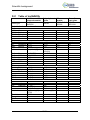
1
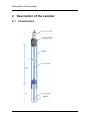
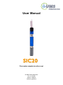
User Manual
S I C 20
Pore water sampler (suction cup)
© UMS GmbH München
Art. no. SIC20
Version 10/2010
Authors: ge/tk/ma
SIC20
Content
1
SIC20
1.1
1.2
1.3
1.4
1.5
2
Safety instructions and warnings
Content of delivery
Foreword
Intended Use
Guarantee
Description of the sampler
2.1
2.2
2.3
2.4
2.5
3
4
4
4
4
5
5
6
Construction
The SIC20 cup
Acrylic glass shaft
Suction tube
Protection tube
6
7
7
7
7
Soil water extraction
8
3.1
Extraction methods
3.1.1
The simple method
3.1.2
The constant vacuum method
3.1.3
Tension controlled extraction
3.2
Experiences and recommendations
3.2.1
Sandy soils
3.2.2
Vacuum ranges
3.2.3
Pore clogging
3.2.4
Achievable sample amounts
3.3
Further notes
8
8
9
9
10
10
10
11
11
12
4
13
Vacuum systems
4.1
4.1.1
4.1.2
4.1.3
4.1.4
4.2
4.3
4.4
4.4.1
4.4.2
4.5
4.5.1
4.5.2
4.5.3
4.6
4.7
4.8
Sampling bottles
Sampling bottle cap
Suitable material
Volumes
Overflow protector
Solution storage
Vacuum buffer bottle
Suction tubes
Tube material
Suction tube dimension
Vacuum tubes
Setup for discontinuous sampling
Setup for constant vacuum method
Setup for Tensiometer controlled vacuum
Level differences
Collection interval
Power management
2/44
13
13
13
14
14
15
15
16
16
16
16
17
17
18
19
20
20
SIC20
5
Installation and operation
5.1
5.2
5.2.1
5.2.2
5.2.3
5.2.4
5.2.5
5.2.6
5.3
5.4
5.4.1
5.4.2
6
6.1
6.2
7
7.1
7.2
7.3
21
Rinsing
Installation
Auger
Slurrying the cup
Jacket tubes
Installation angle
Drilling
Lay the tubes
Assembly and start-up
Collecting sampled solution
Discontinuous method
Continuous method
21
21
21
22
22
22
23
23
23
24
24
24
Service and maintenance
25
Empty suction cups before frost
Cleaning and storage
25
25
Protecting the measuring site
26
Theft and vandalism
Cable and tube protection
Frost
26
26
26
8
Troubleshooting
27
9
Scientific background
28
9.1
Supporting institutes
9.2
Table of suitability
9.3
UMS sampler types
9.3.1
Suction cups
9.3.2
Suction plates
9.3.3
Lysimeter KL2
28
29
30
30
31
31
10 Appendix
32
10.1
10.2
10.3
10.4
32
33
36
37
Technical specifications
Accessories
Glossary
Units
11 Reference list
38
12 Index
40
Your addressee at UMS
44
3/44
SIC20
1 SIC20
1.1
Safety instructions and warnings
Please pay attention to the following possible causes of risk:
Caution! Use only implosion-proof sampling bottles. Danger of
injury!
The ceramic cup is fragile. Excessive load, bending or force can
lead to the break.
Never touch the ceramic cup. Grease, oil or sweat will disturb the
quality.
1.2
Content of delivery
The delivery of a SIC20 includes:
SIC20 pore water sampler with suction tube (standard tube
length 5 m) inside reinforced protection tube
1.3
Foreword
Measuring systems must be reliable and durable and should require
a minimum of maintenance to achieve target-oriented results and
keep the servicing low. Moreover, the success of any technical
system is directly depending on a correct operation.
At the beginning of a measuring task or research project the target,
all effective values and the surrounding conditions must be defined.
This leads to the demands for the scientific and technical project
management which describes all quality related processes and
decides on the used methods, the technical and measurement tools,
the verification of the results and the modelling.
The continuously optimized correlation of all segments and it's
quality assurance are finally decisive for the success of a project.
So please do not hesitate to contact us for further support and
information. We wish you good success with your projects.
Yours,
Georg von Unold
4/44
SIC20
1.4
Intended Use
Pore water samplers are designed to extract soil water from
saturated and non saturated soils. To extract a soil water solution, a
negative pressure has to be applied. The cups are made of a special
ceramic with constant and defined pore distribution with small
chemical activity and adsorption.
1.5
Guarantee
UMS gives a guarantee of 12 months against defects in manufacture
or materials used. The guarantee does not cover damage through
misuse or inexpert servicing or circumstances beyond our control.
The guarantee includes substitution or repair and package but
excludes shipping expenses. Please contact UMS or our
representative before returning equipment. Place of fulfilment is
Munich, Gmunder Str. 37!
5/44
Description of the sampler
2 Description of the sampler
2.1
Construction
SIC20
6/44
Description of the sampler
2.2
The SIC20 cup
The cup consists of Siliciumcarbide. The special manufacturing
process guarantees homogeneous porosity with good water
conductivity and very high firmness. Compared to conventional
porous ceramic the cup is much more durable.
The bubble point is higher than 2 bar.
The cup has been tested by the Technical University Munich, Center
of Life and Food Sciences Weihenstephan, department forest
nutrition and water balance. The applied test procedure has been
proposed to the DIN-NORM committee NAW12/UA5/AK4 for
implementation as a DIN standard.
Suitability as been approved for:
Nitrate
Chloride
Calcium
Kalium
Nickel
Iron
Copper
DOC
Sulphate
Sodium
Aluminium
Phosphate
Magnesia
Chromium
It is not suitable for:
Heavy metals (see chapter “Scientific background”)
Before first use treat the cup as described in chapter “Rinsing”.
2.3
Acrylic glass shaft
With the shaft it is possible to install the sampler in the required
depth. The shaft consists of an extremely resistant Acrylic material
with highest durability against bending, scratches, breakage.
2.4
Suction tube
The suction tube is made of teflon, outer diameter is 3.2 mm and the
inner diameter 1.6 mm. Normally the suction tube is connected to a
sampling bottle with vacuum.
2.5
Protection tube
The reinforced protection tube prevents that the suction tube is
bended or damaged by rodent bite.
7/44
Soil water extraction
3 Soil water extraction
3.1
Extraction methods
To extract soil water in the unsaturated zone the soil water tension
(retention force) has to be surpassed by the sampler‘s potential - a
vacuum needs to be applied.
The vacuum should be as close as possible to the in-situ soil water
tension, as i.e. carbon will fall out in high vacuum.
Variations of the pressure difference between the sampler’s inside
and outside will lead to different filtration results - thus, memory
effects occur. This is prevented by a tension controlled vacuum unit.
Please note that water can only be extracted if water is available.
The bigger the soil pores are, the less water is available at rising
tensions!
Sampling is possible in stony soils up to pF 1, in sandy soils up to pF
2, and in clay soils up to pF 2.7.
Suction cups always act as chemical and physical filter. High
vacuum applied at soils close to saturation cause transport of small
particles into the sampler‘s pores. There is nearly no chance to
reverse this process even by applying pressure, as around the cup
an area of small particles will get accumulated.
The effective active suction force is the difference of soil water
tension and applied vacuum.
UMS offers three different vacuum methods - the most suitable will
depend on your task.
3.1.1
The simple method
Discontinuous evacuation is the simplest method. Evacuate your
sampling bottle down to approx. 50 kPa. If the soil water tension is
lower than 50 kPa, soil water solution will be extracted until vacuum
and soil water tension are equalized. When the samples are
collected, the bottle is evacuated again.
Applications
For qualitative analysis of soil water
Benefits
8/44
Soil water extraction
Low cost
Easy handling
Limits
Discontinuous sampling
Undefined sampling
Tools
Pore water samplers
Hand-operated vacuum floor pump VPS-1 or portable vacuum
case VacuPorter
3.1.2
The constant vacuum method
A constant vacuum is continuously maintained by a regulated
vacuum pump. The vacuum can be set between atmospheric
pressure and 85 kPa.
Leachate samplers for example are supplied with approx. 6 kPa,
while pore water samplers in silt and loam are supplied with 10 to 30
kPa. As clay soils retain water even at higher tensions a vacuum
from 30 to 85 kPa could be applicable.
Applications
Long term monitoring projects
Studies on leachate
Soil water extraction from a certain pore size with a vacuum
which is exactly suitable to the pore size.
Benefits
Defined sampling
Limits
Constant vacuum ignores changing soil water tensions
Tools
Pore water or leachate samplers
Vacuum station VS without controlling Tensiometer
3.1.3
Tension controlled extraction
A Tensiometer measures the soil water tension. The programmable
vacuum station VS automatically supplies a vacuum in
9/44
Soil water extraction
correspondence to the measured tension. Due to the numerous
functions of the unit an optimal adaptation to the sampling task is
possible.
Benefits
Constant sorption and constant filter effects
Prevents memory effects
Limits
Takes samples from various pore sizes depending on the current
vacuum
Tools
Pore water or leachate samplers
Vacuum station VS with controlling Tensiometer
3.2
Experiences and recommendations
3.2.1
Sandy soils
When sampling in coarsely to medium grained sandy soils it can be a
problem that, in the unsaturated range, the water content often is too
low to extract a sufficient amount of solution.
In sandy soils the method with constant vacuum should be applied
as drainage water occurrences are only short. Drainage water will
rush trough quickly and either no solution is won, or only some
solution is extracted by chance.
In contrary, if there are only sand fractions up tp 50% the sampled
amount can be quite high [Riess 1993].
3.2.2
Vacuum ranges
If the applied vacuum is too high the soil around the cup is drained,
and with unfilled soil pores the conductivity drops considerably. The
effect depends on the soil type and is the most significant in sandy
soils.
Therefore, the vacuum should only be as low as necessary. In
general it is sufficient to apply a vacuum which is 20 kPa lower than
the soil water tension (see chapter “Extraction methods”).
10/44
Soil water extraction
With the discontinuous method (consecutive vacuum - no vacuum cycles) the natural water movement is disturbed. Especially in sandy
soils it can happen that the capillary contact ruptures with a
decreasing vacuum.
3.2.3
Pore clogging
Over an extended period of time the ceramic pores might get
clogged by fine particles. To flush the ceramic while installed
normally is just a temporarily solution as the fine material is only
flushed into the area right around the ceramic.
Therefore, clogging should be prevented right from the beginning by
keeping the flow-through low and constant, for example with
Tensiometer controlled vacuum and with a vacuum just a low as
necessary [Riess 1993].
3.2.4
Achievable sample amounts
You can expect the following sample amounts:
Maximum: in free water and with a vacuum of 50 kPa
approximately 5 ml per 10 minutes.
Minimum: in sandy loam soil with 50 kPa approximately 5 ml per
hour.
In high-flow ceramics the flow rate is max. three times as high.
11/44
Soil water extraction
3.3
Further notes
Interfering sorption effects get smaller over a longer period.
In case sampled solution should be stored with protective gas.
As suction cups have a small catchment area heterogeneous
soils cause some difficulties. Depending on the hydraulic contact
to primary or secondary pores (cracks, macro pores) diverse
water is sampled.
As samples can only be extracted from moist soil no sampling is
possible in hot and dry seasons.
Mouse holes can cause some troubles as soil water quickly flows
into deeper layers where it might accumulate [Riess 1993].
Please observe the following:
Long tubes and bubbles in tubes cause a certain resistance. This
has to considered when planning your suction tube system.
To avoid incorrect regulation the vacuum should be measured
close to the pump and not next to the suction cup.
Pump and vacuum units have to be protected from water intrusion
by sufficient measures (overflow protection, adequate volume,
water sensors on vacuum ports).
All parts of a vacuum system have to be implosion proof.
Suction cups should not be installed too close to Tensiometers.
Provide sufficient space between samplers, Tensiometers and soil
moisture probes.
If suction cups and sampling bottle are installed at different levels
you must consider the potential difference when selecting your
vacuum. Please read chapter “Level difference”.
12/44
Vacuum systems
4 Vacuum systems
4.1
4.1.1
Sampling bottles
Sampling bottle cap
The sampling bottle normally picks
up the suction tube of a sampler and
a vacuum tube to evacuate the
bottle.
The cap of the sampling bottle has 3
tube nozzles.
The left (blue) tube as seen on the
photo is the vacuum tube.
The right tube is the suction tube of
the sampler. Insert this tube far
enough into the bottle so the silicone
tube section will not get in contact
with the sampled solution.
The third nozzle is not open but optionally can be used for
connecting another suction tube or to conduct the vacuum to another
sampling bottle. To do so, cut off the tip of the nozzle. Cut off the
upmost section for a thin suction tube or the lower section for a
thicker vacuum tube.
4.1.2
Suitable material
Glass is the best material for sampling, storage and transportation. If
a vacuum is applied to a glass bottle it must be implosion proof.
Glass bottles must have a plastic coating as an implosion protection.
UMS supplied sampling bottles type SF are implosion proof.
Bottles made of polyethylene, polypropylene or polyamide normally
are not suitable for applying a vacuum, but, depending on the
substances, can be used for transportation or storage of the solution.
13/44
Vacuum systems
4.1.3
Volumes
UMS bottles are available with a volume of half
litre (SF-500), 1 litre (SF-1000) or 2 litres (SF2000).
Which size is the best depends on the
application:
1. What sample amounts are expected during
which interval?
2. Are several samplers connected to the bottle
for getting a mixed sample?
3. With discontinuous sampling the sampling
bottle is also the vacuum buffer. Note that the
vacuum is already used up when the bottle is
only partially filled with solution. Therefore, the
sampling bottle should have 3 times of the
volume you want to sample at least with the
discontinuous sampling method.
4.1.4
Overflow protector
An optional overflow protector which is inserted into the sampling
bottle is available for usage in automatic vacuum systems (see left
photo).
The valve consists of a capillary membrane which is permeable to air
when dry, but tight if it gets wet. The overflow protector prevents that
soil water solution is drawn out of the sampling bottle and into the
vacuum unit. As soon as the sampling bottle is full the protector
closes. Thus, this bottle is cut off from the vacuum system while the
other bottles still continue to work.
Simply attach the SF-protect to the end of the vacuum tube. The
protector opens up again as soon as the sampling bottle is emptied.
If the overflow protection valve SF-protect is used the flow resistance
is higher. Therefore, an additional buffer bottle (2 liter) should be
inserted before the vacuum unit.
Note that then the vacuum system has to have a main line, and each
sampling bottle is connected to the mail line with T-fittings (see right
photo).
14/44
Vacuum systems
The purpose of the overflow protection is to prevent damages to the
vacuum unit and to avoid that solution from one bottle contaminates
other bottles in case of unexpected incidents. It is not intended as an
automatic stop switch, mainly because the membrane has to
completely dry off before it again is permeable to vacuum.
Therefore, the size of the sampling bottles and the collection interval
should ensure that no overflow occurs at all.
A further buffer bottle still is recommendable.
4.2
Solution storage
The soil water samples should be stored dark and at soil
temperature. Therefore, the sampling bottles can be placed in a
buried box, so the storage temperature is identical to the soil
temperature, and the samples are protected against sunlight.
The sampled solution should be stored dark and at soil
temperature to prevent algae growth, for example inside a buried
box.
4.3
Vacuum buffer bottle
In automatic vacuum systems it is recommendable to insert a buffer
bottle before the input of the vacuum pump. It prevents that water
enters the pump in case a sampling bottle overflow. It also serves as
a vacuum buffer.
UMS vacuum units VS to VS-pro (not the VacuPorter) have a water
intrusion detector which will shut off the pump when water enters the
15/44
Vacuum systems
vacuum port. Note that the unit remains shut down until the detector
has completely dried out again.
4.4
Suction tubes
4.4.1
Tube material
Suitable material for the suction tube (also check the suitability list in
the appendix):
Polyethylene, polypropylene or polyamide: for anions and
cations.
Stainless-steel capillary tubes: for all substances but not for
metals and heavy metals.
UMS samplers are designed that the sampled solution will not have
contact to any material other than the cup material and the suction
tube material if connected properly.
4.4.2
Suction tube dimension
In general suction tubes should be as short as possible for the
following reasons:
Little dead volume and real-time sampling.
Low reflow with rising water tension as the solution left inside the
tube is always drawn back into the soil.
Least possible flow resistance.
Air bubbles inside the tube create a high flow resistance which will
be highest in thin and long tubes. In a 20 meter long tube with an
inner diameter of 1.6 mm the flow resistance in worst case can be up
to 50 kPa.
Please refer to chapter „Installation“ for instructions how to install the
suction tubes.
4.5
Vacuum tubes
Observe the following points about the vacuum tube:
Keep vacuum tubes as short as possible. With longer tubes the
risk of leakage, damage or rodent bite rises.
16/44
Vacuum systems
The distance between the pump/vacuum unit can be up to 200
meters. In a tight system the pumped volume will be low and
pressure drop is neglectable.
Recommendable inner diameter for a vacuum tube is 4 to 10
mm. Select the inner diameter depending on the tube lengths,
number of samplers and the sampling method.
You must ensure that the complete system is tight.Possible setups
As described in chapter „Extraction methods“ there are three
possible sampling methods. Following some suggestions how to
assemble a system depending on the sampling method.
4.5.1
Setup for discontinuous sampling
A soil water sampler is connected to a sampling
bottle. The sampling bottle is evacuated, for
example with the vacuum floor pump VPS-2 or
the VacuPorter. Solution is extracted from the soil
until the decreasing vacuum drops below the soil
water tension.
Note: the sample amount can be max. 2/3 of the
bottle volume.
4.5.2 Setup for constant vacuum
method
Each soil water sampler is connected to a sampling bottle. With a
vacuum tube network several sampling bottles are connected to a
vacuum controlling unit like the VS units. The vacuum units are set to
the desired vacuum and keep up a constant vacuum by controlling
and re-establishing the vacuum.
Note the following when connecting sampling bottles:
Several sampling bottles can be connected in a row by using the
third tube connection on the sampling bottle cap (upper scheme on
the next page), or by using T-fittings (lower scheme).
If a sampling bottle is equipped with an overflow protection valve
(see chapter above) you must use T-fittings as a blocked valve
would block the whole system.
17/44
Vacuum systems
In systems with automatic vacuum units sufficient measures should
be applied to avoid that the pump draws up water or the system gets
blocked by overflowing bottles.
Fig: Sampling bottles connected in row using 3rd nozzle on the cap
Fig: Sampling bottles connected to main vacuum line with T-fittings,
Tensiometer and overflow valves are optional
4.5.3
Setup for Tensiometer controlled vacuum
Samplers, sampling bottles and vacuum tubes are connected the
same way as with the constant vacuum method (see figures above).
A controlling Tensiometer is connected to the VS unit and the
vacuum is regulated in dependence of the current soil water tension.
18/44
Vacuum systems
4.6
Level differences
It is recommendable to place the sampling bottle at the same height
as the suction cup. Consider the following if this is not the case.
If a sampling bottle is placed in a higher level than the suction cup
(left figure) the level difference causes a pulling water column which
reduces the effective vacuum on the sampler. If for example the
suction cup is 1 meter beneath the level of the bottle the vacuum at
the sampler is approximately 10 kPa lower than the vacuum inside
the bottle.
To compensate the level difference when the sampling bottle is
higher than the suction cup add 1 kPa to the vacuum for each 10
cm of level difference (or exactly 0.98 kPa per 10 cm water
column).
Accordingly, if the sampling bottle is lower than the suction cup, for
example in a manhole (right figure), the effective vacuum on the
sampler is higher than inside the bottle - if the tube is completely
filled with water. In a normal situation there will be vapor and bubbles
inside the tube. Therefore, you do not reduce the vacuum so solution
is extracted even with bubbles inside the tube.
Do not compensate the level difference if the sampling bottle is
lower than the suction cup.
19/44
Vacuum systems
4.7
Collection interval
It depends on the research task how often the extracted solution
should be collected from the sampling bottles.
For long term monitoring studies an interval of 1 to 2 weeks might be
applicable. If you want to specifically gain the peaks from intense
rain incidents the collection time should be shorter.
If you want to know the chronological change of the sample amount
you can place the sampling bottle on a scale and log the weight with
a data logger, or insert a vacuum-tight tipping counter with logger
before the sampling bottle.
4.8
Power management
A soil water extraction system which cannot be supplied by mains
power requires either battery, solar or wind energy. It is necessary to
establish a power management plan in consideration of amount and
intervals of extraction, possible leakage and shut-down.
20/44
Installation and operation
5 Installation and operation
5.1
Rinsing
Always rinse each ceramic cup or plate with 500 to 2000 ml deionised water, and then condition them with the adequate soil water
solution.
If there is enough time before the first samples should be analyzed
you can do without rinsing and then discard the samples from the
first week, or at least 1000 ml.
It might be considerable to discard an amount of 500 to 2000 ml of
your first won samples.
When charged with high amounts of acidity sintered ceramic
materials corrode and release Aluminium. Therefore, we strictly
oppose to rinse the ceramics with acid solution, although this is
recommended in some literature.
We do not recommend to rinse the cup with hydrochloric acid as
this might destruct the cup. This will breach the warranty!
Before installation it is recommendable to immerse ceramic cups
in de-ionised water for some time, preferably over night, so the
pores will be water saturated.
5.2
5.2.1
Installation
Auger
The ceramic cup has to have a good capillary contact to the soil
matrix. Therefore, the ceramic cup should fit into the drilling as tight
as possible. To achieve this, the auger tip should exactly have the
same diameter as the cup.
The shaft itself should have a space of 1 to 2 mm for easy insertion,
low disturbance and possibility to control the fitting of the cup.
UMS offers the special gouge auger TB-20 with a tapered tip as an
accessory. This auger has a diameter of 20 mm on the first 5 cm of
the tip, and 22 mm on the further section.
21/44
Installation and operation
5.2.2
Slurrying the cup
It is only recommendable to slurry the ceramic cup in a highly sandy
or stony soil. Slurry the cup with a paste made of the soil taken from
the bottom of the augered hole. Optionally you may use washed
quartz sand (mesh size 1200).
Mix a viscous paste with water and fill it into the hole with a properly
sized pipe. In horizontal installations blow the paste into the pipe.
Note that fine material might be washed out by heavy drainage
water. Then, the cup might lose it's capillary contact to the soil. In
this case repeat the slurrying.
Also note that sandy soils drain quickly (see pF/wc curve for sandy
soils). Therefore, soil solution can only be extracted with a suction
cup at low soil water tension (pF < 2 or unbound water). Sandy soils
drier than -10 kPa only have small volumetric content of water as
large pores are already vented.
5.2.3
Jacket tubes
Specially in coarse sand or pebbly soils it might be necessary to
install jacket tubes as a drilled hole collapses before the suction cup
is inserted.
If the samplers are installed in jacket tubes ensure that condensed
water or leachate is conducted away from the suction cup. In
horizontal installation a decline of 3% towards the manhole is
suitable.
Note that the jacket tubes should not be installed closer than 50 cm
away from the suction cup.
If the jacket tubes are installed with percussion drilling machine the
final 100 cm should not be rammed but manually drilled to prevent
compaction of the soil.
Beside in compact sand also drilling rockets can be used.
5.2.4
Installation angle
The sampler should be installed in a way that the major flow path is
not disturbed by the sampler’s shaft.
If for example the flow path is vertical the shaft should be installed
with an angle of at least 20° away from the vertical line.
22/44
Installation and operation
5.2.5
Drilling
Put a mark on the auger to drill to the proper depth.
Take away the organic layer with a shovel to avoid that the auger
pushes organic material into lower layers.
Drill the hole.
If required insert the slurry paste into the hole with a pipe.
Immediately insert the sampler. In pebbly soils you only have 10
seconds until the slurry paste might drain away.
Do not use force when inserting the shaft. Do not use tools or a
hammer.
The SIC20 sampler has a black mark on the top end of the shaft. If
the shaft is not installed vertically this mark should point upwards then the opening of the suction tube inside the cup is at the lowest
position of the cup.
In case put pack the organic layer and tighten the soil to close the
gap between the shaft and the augered hole.
Push the supplied rubber surface water retaining disk over the
shaft to prevent that surface water runs along the shaft. Optionally
the top part of the hole can be sealed with swellable Bentonite
pellets.
5.2.6
Lay the tubes
Tubes should be buried in a depth of at least 10 cm. If the system
should work year round the suction tubes have to be installed in a
frost free depth.
UMS supplied samplers have a reinforced protective tube which
protects the suction tube. It is recommendable to insert tubes without
a protective tube in proper plastic protection tubes.
5.3
Assembly and start-up
Insert each suction tube into a sampling bottle. In a discontinuous
system attach your vacuum pump to each sampling bottle, create the
required vacuum and then lock the bottle.
In an extended vacuum system connect all sampling bottles with
vacuum tubes and with your vacuum unit. Start to evacuate the
23/44
Installation and operation
system. Please refer to the manual of your vacuum unit for
instructions.
A vacuum should assemble. If no vacuum is established, check your
system for leaks.
With the first won solution the system is flushed. Discard the first
samples.
5.4
5.4.1
Collecting sampled solution
Discontinuous method
UMS sampling bottles are either plugged with
a clamp or with a fitting as seen the photo.
Open the vacuum tube to vent the bottle.
Screw off the cap and collect the sample, or
replace the bottle with a clean one.
Put back the bottle cap and evacuate the
bottle with your pump. Now bend the vacuum
tube to seal it and remove your pump.
Reattach the fitting or the clamp.
5.4.2
Continuous method
In a system with continuous vacuum, switch off the vacuum unit.
Then vent the system. Now collect all samples from the sampling
bottles and reassemble the system.
In case check the Tensiometer readings and the sampled amounts
and adjust the settings of your vacuum unit.
24/44
Service and maintenance
6 Service and maintenance
6.1
Empty suction cups before frost
If suction cups should remain installed during periods with
temperatures below freezing point, they must be emptied to prevent
frost damage. Please note, that in times free of snow but with air
temperatures below 0°C, the area of frost declines from the soil
surface into deeper soil horizons.
Required tools for emptying: One retaining tube clamp for each
suction cup, a syringe (50 ml) and a vacuum pump.
How to proceed:
With the vacuum pump, completely extract the water left in the
suction cup.
Attach the syringe to the extraction tube. Press 20 ml of air into
the cup to achieve a positive pressure of approx. 100 hPa.
Lock the extraction tube with a tube clamp to keep up the
overpressure.
As soon as water inside the extraction tube is frozen, the suction
cup cannot be emptied anymore. The ceramic cup might be
damaged by the frozen water.
6.2
Cleaning and storage
For cleaning, wipe of the shaft with a moist cloth. The suction cups
should be stored in a position where a deformation of the shaft is
avoided.
Do not touch the ceramic with your fingers.
25/44
Protecting the measuring site
7 Protecting the measuring site
7.1
Theft and vandalism
The site should be protected against theft and vandalism as well as
against any farming or field work. Therefore, the site should be
fenced and signposts could give information about the purpose of the
site.
7.2
Cable and tube protection
Cables and tubes should be protected against rodents with plastic
protection tubes. UMS offers dividable protection tubes as
accessory. For long term studies we recommend to dig cables and
tubes a few centimetres below soil surface inside protection tubes.
7.3
Frost
For all-season operation install suction tubes in a frost-free depth
and the sampling bottles in an insulated and buried box.
26/44
Troubleshooting
8 Troubleshooting
If no or only a little amount of water is extracted over a longer period
of time please check the following:
If you have an automatic regulation, for example with the VS
vacuum station, and the pump repeatedly switches on the reason
could be a leak in the system. Check all tubes and connections
for tightness.
Sampling cups have a very small sphere of influence. Depending
on their hydraulic contact the sampler either extracts water from
the primary pores or, specially in heterogeneous soils, the
secondary pores (cracks, macro pores). Therefore, results can
turn out variously in extremely heterogeneous soils.
As water can only be extracted from a moist soil results can be
poor during summer or in dry soils.
Pathways caused by mouse holes or roots quickly conduct water
into lower horizons where the water accumulates [Riess 1993].
Fine particles can clog the ceramic pores over the time. To flush
the ceramic while installed will only have a short-lived success as
the particles are only moved into the surrounding soil. Clogging
should be diminished from the beginning by keeping the flow rate
as low and as constant as possible, for example by a tension
controlled vacuum. The vacuum should only be as high as
required. Test have shown that these measures reduce clogging
[Riess 1993].
27/44
Scientific background
9 Scientific background
9.1
Supporting institutes
The recommendations in this manual were written in cooperation
with the following institutes:
Österreichischen Bundesamt für Wasserwirtschaft
Petzenkirchen, Österreichischen Arbeitsgruppe Lysimeter,
http://www.lysimeter.at/
University of Hohenheim and Technical University Munich,
Forschungszentrum für Umwelt und Gesundheit Neuherberg,
Bayerischen Landesanstalt für Wald und Forstwirtschaft
Bayerischen Landesamt für Wasserwirtschaft.
These recommendations compile some basic information and
experiences for the extraction of soil water. This cannot be
exhaustive and cannot replace detailed consulting as the complete
process, sampling conditions, soil type, extraction method and
intervals, sample storage and last but not least the analysis have to
be designed in accordance with the individual task.
Note:
The information for suitability of materials on the following page base
on experienced data, laboratory analysis or (unevaluated) citation in
literature. It was initially created in a UMS workshop about soil water
sampling in the year 2000 and is elaborated since. The list is
published in all conscience but makes no claim to be complete, and
therefore cannot replace specific consulting. Please do not hesitate
to contact us.
Furthermore, we would be grateful to learn about your experiences
and recommendations.
28/44
Scientific background
9.2
Table of suitability
Al2O3 ceramic
sintered material
SK20
UMS type:
SKPE25
Suitable for determination of ...
Anions:
NO3- Nitrate
+++
SO42- Sulphate
+++
PO43- Phosphate +++
ClChloride
+++
Polyethylene/
Nylon
Silicon
carbide
SIC20, SIC40
SIC300
Borosilicate glass
SG25
SPG120
+++
+++
+++
+++
+++
+++
+++
+++
+++
+++
+++
+++
+++
+++
+++
+++
+ [1]
++
+++
+++
+++
+++
+++
+++
+++
+++
+++
+++
SPE20
Cations:
Ca2+ Calcium
K+
Potassium
Na+
Sodium
NH4+ Ammonium
Al3+
Aluminium
+ [1]
+ [1]
++[1]
+++
---(critical [2])
Cu2+
Cr2+
Fe2+
Mg2+
Ni2+
---[3] [5][8]
-- [2]
---
++ [1]
++ [1]
+ [1]
+++
++(critical with
pH<2[1])
+++
+++
+++
+++
+++
+ [1]
++ [2]
---
+ [1]
+++
+++
+++
+++
-
+++
+++
+++
++ [8]
++ [1]
++[3]
+ [1]
++
++
+
+
--- [6]
--- [5] [6]
+[6]
+[6]
-
-
+ (Atrazin) [3]
[7][8]
/
/
+(Atrazin) [7]
/
/
/
/
/
-
/
/
Copper
Chromium
Iron
Magnesia
Nickel
Elements
S
Sulphur
P
Phosphorus
Si
Silicon
DOC
TOC
Humins:
Heavy metals:
Cd
Cadmium
Pb
Lead
Herbicides
Pesticides
Fungicides
PAK
Trace elements
29/44
+++
+++
Scientific background
Literature source
[1] Göttlein, 1996
[2] Grossmann et al., 1987
[3] Klotz, Unold, 2000
[4] Riess, 1993
[5] Guggenberger und Zech 1992
[6] Haberhauer 1997
[7] Schroll 1996
[8] Klotz, 1997
9.3
9.3.1
Caption
--- completely unsuitable
-- unsuitable
- only for experts, requires good knowledge
and suitable conditioning of the suction cups
/
no experiences
+ limited suitability
++ suitable after conditioning and sufficient
forerun for flushing
+++suitable after sufficient forerun for flushing
UMS sampler types
Suction cups
SK20
SK20 simple ceramic cup with removable shaft. For continuous and
discontinuous extraction. Suitable for determination of nitrate and
common organic and inorganic substances.
SIC20
Pore water sampler SIC20 with removable shaft like the SK20, but
with a SiC silicon carbide cup instead of the ceramic cup. SiC is
sintered at 2500°C and is less absorbent/desorbent than ceramic or
borosilicate. The bubble point 90 kPa. UMS SiC cups are patented.
SPE20
Instead of a ceramic cup the SPE20 pore water sampler has a
porous PE-nylon-membrane which is specially suitable for heavy
metals and whenever ceramics are inappropriate.
SKPE25
The sampled solution is stored inside the shaft and is collected by
applying a pressure to the additional tube. With ceramic cup.
SG25
Pore water sampler with porous borosilicate glass cup. Borosilicate
is suitable for phosphate and DOC. Available with a diameter of 20
mm or 25 mm
30/44
Scientific background
9.3.2
Suction plates
SIC300
Suction plate made of porous silicon carbide for laboratory use or
field leachate sampling. The plate is backed with a butyl rubber foil
and a bottom tube connector to apply a 6 kPa vacuum. Bubble point
is 10 kPa.
SPG120
Leachate sampling plate made of porous borosilicate glass. Suitable
for phosphate and DOC. With tube connector ending inside the
plate’s center. Utility patented.
9.3.3
Lysimeter KL2
The leachate bucket can be buried in situ to collect leachate - or can
be used as a laboratory soil column and lysimeter. On the bottom of
the polyethylene bucket a 0.5 bar high flow ceramic plate is fixed.
31/44
Appendix
10 Appendix
10.1 Technical specifications
Technical Specifications SIC20
Shaft
PMMA 20 mm
Extraction tube
teflon, inside - 1.6 mm, outside- 3.2
mm
Protective tube
PVC, with reinforced fabric, 11 x 5 mm
Cup type
Silicium-Carbid-Cup
Cup size
Length: 60 mm 0,8, 20 mm - 0.5
Active surface
34 cm2 1
Filling volume
8 ml
1
Cup porosity
45 % 2 %
Pore size
Approx.: 2 m
32/44
Appendix
10.2 Accessories
Description
Portable vacuum case without regulation, internal pump for
max. vacuum -85 kPa (-0.85 bar) or pressure max. 3.5 bar,
rechargeable battery 7 Ah, particle filter, gauges for vacuum
and pressure, in watertight storm case 30x25x13 cm, 4.8 kg;
supplied incl. recharger 230 VAC
Please order additionally: Mains recharger 110 VAC ... 230
VAC, for VacuPorter, incl. set of international plug adapters
Hand-operated vacuum floor pump, volume 410 ml per
stroke, achievable vacuum 0
-80 kPa, aluminum body,
steel foot, height 57 cm, weight 2 kg, for evacuation of larger
volumes
VacuPorter
VPS-2
Sampling bottle
Sampling bottle 500 ml, implosion protected, with screw cap
for up to 3 tubes
Sampling bottle 1000 ml, implosion protected, with screw cap
for up to 3 tubes
Sampling bottle 2000 ml, implosion protected, with screw cap
for up to 3 tubes
Spare cap for sampling bottle GL45, blue
Clip for wall mounting of sampling bottles
Art. no.
VacuPorter
vp.110VAC
VPS-2
SF-box
SF-500
SF-1000
SF-2000
SFK
SF-CLIP
PVC-box for 6 sampling bottles, L 400 x B 300 x H 350 mm, SF-BOX
incl. 6 lead-throughs PG9
Insulated box, dimension outside 600 x 400 x 365 mm, inside SF-ISOBOX
510 x 310 x 300 mm, incl. 14 lead-throughs PG9 for
protective tubes
SF-Protect
Automatic overflow valve for sampling bottles
33/44
Appendix
SF-protect
VS-pro
VS-single
Vacuum systems
2-channel vacuum unit for two adjustable vacuum circuits
0...-85 kPa, one controllable with optional Tensiometer T4 or
T8, display keypad, Aluminum enclosure 26x16x22cm, IP66,
incl. tensioLink connector tL-8/USB-Mini and software
tensioVIEW
2-channel vacuum system, without display/keypad,
adjustable vacuum pump 0 -85 kPa, for two constant
vacuum circuits, one controllable with optional Tensiometer
T4 or T8, Aluminium enclosure 26x16x22cm, IP66, incl.
tensioLINK connector tL-8/USB-Mini and software
tensioVIEW
1-channel vacuum system, incl. adjustable vacuum pump 0
-85 kPa, for one constant vacuum circuit, controllable with
optional Tensiometer T4 or T8, Aluminium enclosure
26x16x22cm, IP66, tensioLINK interface RS485 for external
data logger connection
34/44
VS-pro
VS-twin
VS-single
Appendix
b.TB-20 TBE-100
Special gouge auger, shaped tip for UMS-Tensiometers and b.TB-20
UMS-suction cups, diameter 20 mm, length 1250 mm, with
hammering head (without elongation)
Gouge auger elongation 100 cm for Tensiometer and suction b.TBE-100
cup augers
Cable protection tube, inner diam. 8,7 mm, max. cable diam.
4 mm, dividable
Cable protection tube, inner diam. 12,5 mm, max. cable
diam. 7 mm, dividable
Cable protection tube, inner diam. 24,2 mm, max. cable
diam. 14 mm, dividable
Cable protection tube, inner diam. 30,0 mm, max. cable
diam. 18 mm, dividable
35/44
ks.DN-10
ks.DN-14
ks.DN-23
ks.DN-37
Appendix
10.3 Glossary
Suction cup, pore water sampler or lysimeter
Different terms are common. In this context it is an instrument
consisting of a hydrophilic membrane, shaft and suction tube which
is used to extract soil water solution from unsaturated zones.
We do not use the term lysimeter for pore water samplers as we
define a lysimeter as a monolithic soil column.
Lysimeter
Container with defined surface, filled with soil and with at least one
outlet. Used for quantification of water and substance flows,
decay/reaction processes and simulation.
Tensiometer
Instrument for measuring soil water tension.
Vacuum
Pressure below atmospheric pressure.
36/44
Appendix
10.4 Units
pF
hPa
kPa=J/kg
MPa
bar
psi
%rH
1
-10
-1
-0,001
-0,01
-0,1450
99,9993
2,01
-100
-10
-0,01
-0,1
-1,4504
99,9926
2.53
-330
-33
-0,033
-0,33
-4,9145
99,9756
Tensiometer
2.93
ranges*
-851
-85,1
-0,085
-0,85
-12,345
3
-1.000
-100
-0,1
-1
-14,504
99,9261
4
-10.000
-1.000
-1
-10
-145,04
99,2638
-15.136
-1.513
-1.5
-15
-219,52
98,8977
5
-100.000
-10.000
-10
-1 00
-1.450,4 92,8772
Air-dry**
6
-1.000.000
-100.000
-100
-1 000
-14.504
47,7632
Oven-dry
7
-10.000.000 -1.000.000 -1.000 -10 000 -145.038
0,0618
Wet
Field
capacity
Permanent
4.18
wilting point
* standard measuring range of Tensiometers
** depends on air humidity
Note: 1 kPa corresponds to 9,81 cm water column
37/44
Reference list
11 Reference list
Czeratzki, W.; 1971: Saugvorrichtung für kapillar gebundenes
Bodenwasser. Landforschung Völkerode 21, 13-14
DVWK; 1990: Gewinnung von Bodenwasserproben mit Hilfe der
Saugkerzenmethode. DVWK Merkblätter, Heft 217
DVWK; 1980: Empfehlungen zum Bau und Betrieb von Lysimetern
Grossmann,
J.;
Quentin,
K.-E.;
Udluft,
P.;
1987:
Sickerwassergewinnung mittels Saugkerzen – eine Literaturstudie.
Z. Pflanzenernährung u. Bodenkunde 150, 281-261
G.HENZE, 1999: Umweltdiagnostik mit Mikrosystemen, Verlag
Wiley-VCH, ISBN 3-527-29846-0.
RAMSPACHER,
P.,
1993:
Erste
Erfahrungen
mit
tensiometergesteuerten Unterdrucklysimetern zur Erstellung von
Sickerwasserbilanzen (Lysimeterstation Wagna), Bericht über die 3.
Gumpensteiner Lysimetertagung „Lysimeter und ihre Hilfe zur
umweltschonenden
Bewirtschaftung
landwirtschaftlicher
Nutzflächen“, BAL Gumpenstein, 20.-21.4.1993, S. 67-72.
HARTGE, HORN, 1992: Die physikalische Untersuchung von
Böden, Verlag Enke, ISBN 3 432 82123 9.
FEICHTINGER, F., 1992: Erste Erfahrungen beim Einsatz eines
modifizierten Feldlysimeters, Bericht über die 2. Gumpensteiner
Lysimetertagung „Praktische Ergebnisse aus der Arbeit mit
Lysimetern“, BAL Gumpenstein, 28.-29.4.1992, S. 59-62.
KLAGHOFER, E., 1994: Antworten auf die 7 Fragen an uns
Lysimeterbetreiber,
Bericht
über
die
4.
Gumpensteiner
Lysimetertagung „Übertragung von Lysimeterergebnissen auf
landwirtschaftlich genutzten Flächen und Regionen“, BAL
Gumpenstein, 19.-20.4.1994, S. 5-7.
ROTH, D., R. GÜNTHER und S. KNOBLAUCH, 1994: Technische
Anforderungen an Lysimeteranlagen als Voraussetzung für die
Übertragbarkeit von Lysimeterergebnissen auf landwirtschaftliche
Nutzflächen, Bericht über die 4. Gumpensteiner Lysimetertagung
„Übertragung von Lysimeterergebnissen auf landwirtschaftlich
38/44
Reference list
genutzten Flächen
20.4.1994, S. 9-21.
und
Regionen“,
BAL
Gumpenstein,
19.-
SCHWABACH, H. und H. ROSENKRANZ, 1996: Lysimeteranlage
Hirschstetten - Instrumentierung und Datenerfassung, Bericht über
die 6. Gumpensteiner Lysimetertagung „Lysimeter im Dienste des
Grundwasserschutzes“, BAL Gumpenstein, 16.-17.4.1996, S. 41-45.
KRENN, A., 1997: Die universelle Lysimeteranlage Seibersdorf Konzeption, Bericht über die 7. Gumpensteiner Lysimetertagung
„Lysimeter und nachhaltige Landnutzung“, BAL Gumpenstein, 7.9.4.1997, S. 33-36.
EDER, G., 1999: Stickstoffausträge unter Acker- und Grünland,
gemessen mit Schwerkraftlysimetern und Sickerwassersammlern,
Bericht über die 8. Gumpensteiner Lysimetertagung „Stoffflüsse und
ihre regionale Bedeutung für die Landwirtschaft“, BAL Gumpenstein,
13.-14.4.1999, S. 93-99.
KUNTZE,
ROESCHMANN,
SCHWERDTFEGER,
Bodenkunde, Verlag UTB Ulmer, ISBN 3-8001-2563-3.
1988:
Starr, J.L.; Meisinger, J.J. ; Parkin, T.B.; 1991: Experience and
knowledge gained from vadose zone sampling. In: NASH, R.G.;
Leslie A.R. (Eds.): Groundwater Residue Sampling Design. Am.
Chem. Soc. Symp. Series 465, 279-289
Udluft, P.; Quentin, K.-E.; Grossmann, J.; 1988: Gewinnung von
Sickerwasser
mittels
Saugkerzen
–
Verbesserung
der
Probenahmetechnik und Minimierung der Veränderung der
chemischen und physikalischen Eigenschaften des Sickerwassers.
Abschlußbericht zum Forschungsvorhaben DU 3/10-1. Institut für
Wasserchemie der TU München.
39/44
Index
12 Index
A
I
Air bubbles ......................................16
auger...............................................23
implosion proof ...............................13
in-situ soil water tension ...................8
B
J
black mark.......................................23
buffer bottle .....................................15
buried box .......................................26
jacket tubes.....................................22
L
C
leakage ...........................................20
Level differences.............................19
capillary contact ..............................21
clay soils ...........................................8
constant vacuum method............9, 17
M
D
maintenance .....................................4
memory effects .................................8
de-ionised water..............................21
DIN-NORM........................................7
discontinuous sampling...................17
drainage water ................................10
N
NAW12/UA5/AK4..............................7
F
O
frost-free..........................................26
organic layer ...................................23
overflow valve .................................14
G
P
Guarantee .........................................5
Pore clogging..................................11
40/44
Index
protection tube ..................................7
protection tubes ..............................26
T
R
Technical specifications..................32
Tensiometer controlled vacuum......18
Tension controlled extraction............9
Rinsing ............................................21
U
S
UMS Workshop...............................28
unsaturated zone ..............................8
sample amounts..............................11
sampling bottle................................13
sand fraction ...................................10
sandy soils ........................................8
Sandy soils......................................10
shaft ..................................................7
simple method...................................8
sorption effects................................12
stony soils .........................................8
suction tube.......................................7
suction tubes...................................16
Suitability...........................................7
V
vacuum tubes .................................16
W
water conductivity .............................7
water intrusion detector ..................15
41/44
Index
42/44
Index
43/44
Your addressee at UMS
Your addressee at UMS
Sales:
Georg v. Unold
Tel:+49-89-126652-15
Email: [email protected]
About this manual:
Thomas Keller
Tel:+49-89-126652-19
Email: [email protected]
UMS GmbH
D-81379 München
Gmunderstr. 37
email: [email protected]
Ph.: +49-89-126652-0
Fax: +49-89-126652-20
Strictly observe rules for disposal of
equipment containing electronics.
Within the EU: disposal through municipal
waste prohibited - return electronic parts
back to UMS.
Rücknahme nach Elektro G
WEEE-Reg.-Nr. DE 69093488
44/44