1
MVX9000 AF Drives
User Manual
Safety Instructions
Safety Messages
For the best results with the MVX9000 inverter, carefully read this manual and all of
the warning labels attached to the inverter before installing and operating it, and follow
the instructions exactly. Keep this manual handy for quick reference.
Definitions and Symbols
A safety instruction (message) includes a hazard alert symbol and a signal word,
WARNING or CAUTION. Each signal word has the following meaning:
HIGH VOLTAGE: This symbol indicates high voltage. It calls your attention
to items or operations that could be dangerous to you and other persons
operating this equipment. Read the message and follow the instructions
carefully.
This symbol is the “Safety Alert Symbol.” It occurs with either of two signal
words: CAUTION or WARNING, as described below.
WARNING: Indicates a potentially hazardous situation which, if not
avoided, can result in serious injury or death.
CAUTION: Indicates a potentially hazardous situation which, if not avoided,
can result in minor to moderate injury, or serious damage to the product.
The situation described in the CAUTION may, if not avoided, lead to serious
results. Important safety measures are described in CAUTION (as well as
WARNING).
Hazardous High Voltage
HIGH VOLTAGE: Motor control equipment and electronic controllers are
connected to hazardous line voltages. When servicing drives and electronic
controllers, there may be exposed components with housings or
protrusions at or above line potential. Extreme care should be taken to
protect against shock.
Stand on an insulating pad and make it a habit to use only one hand when
checking components. Always work with another person in case an
emergency occurs. Disconnect power before checking controllers or
performing maintenance. Be sure equipment is properly grounded. Wear
safety glasses whenever working on electronic controllers or rotating
machinery.
Cutler-Hammer MVX9000 User Manual
i
Safety Instructions
Warnings, Notes and Cautions
Always read this manual thoroughly before using MVX9000 AC
Motor Drives.
HIGH VOLTAGE!
Be sure to ground the unit. Otherwise, there is danger of
electric shock and/or fire.
HIGH VOLTAGE!
Wiring work shall be carried out only by qualified personnel.
Otherwise, there is a danger of electric shock or fire.
WARNING!
AC input power must be disconnected before any
maintenance. Do not connect or disconnect wires and
connectors while power is applied to the circuit. Maintenance
must be performed by qualified technicians.
WARNING!
A hazardous voltage charge may still remain in the DC-link
capacitor even if the power has been turned off. To avoid
personal injury, do not remove the cover of the AC drive until
all “DISPLAY LED” lights on the digital keypad are off. Please
note that there are live components exposed within the AC
drives. Do not touch these live parts.
WARNING!
The AC drive may be destroyed beyond repair if incorrect
cables are connected to the input/output terminals. Never
connect the AC drive output terminals T1, T2, and T3 directly to
the AC main circuit power supply.
WARNING!
Hazardous Voltage
Before opening the AC drive covers:
Disconnect all power to the AC drive.
Wait five minutes for DC bus capacitors discharge.
Any Electrical or mechanical modification to this equipment
without prior written consent of Eaton Cutler-Hammer will void
all warranties and may result in a safety hazard in addition to
voiding the UL listing.
ii
Cutler-Hammer MVX9000 User Manual
Safety Instructions
WARNING!
Wait at least 2 minutes after all display lamps have gone out,
and then confirm that the capacitors have fully discharged by
measuring the voltage between B1 and Ground using a multi
meter set to measure DC.
WARNING!
Opening the Drive voids the warranty!
WARNING!
Make sure that all screws are tightened to the proper torque
rating shown in Table 3-2.
WARNING!
This equipment should be installed, adjusted, and serviced by
qualified electrical maintenance personnel familiar with the
construction and operation of the equipment and the hazards
involved. Failure to observe this precaution could result in
bodily injury.
WARNING!
“Use 75℃ Cu wire only” or equivalent.
WARNING!
“Suitable for use on a circuit capable of delivering not more
than 5,000 rms symmetrical amperes, 240 V maximum.”
WARNING!
“Suitable for use on a circuit capable of delivering not more
than 5,000 rms symmetrical amperes, 480 V maximum.”
WARNING!
Disconnect AC power before proceeding!
CAUTION!
There are highly sensitive MOS components on the printed
circuit boards. These components are especially sensitive to
static electricity. To avoid damage to these components, do
not touch these components or the circuit boards with metal
objects or your bare hands.
Cutler-Hammer MVX9000 User Manual
iii
Safety Instructions
CAUTION!
Ground the MVX9000 using the ground terminal. The
grounding method must comply with the laws of the country
where the AC drive is to be installed. Refer to the Basic Wiring
Diagram in Chapter 3.
CAUTION!
Do not connect the AC power to the T1, T2, T3 terminals, it will
damage the AC drive.
CAUTION!
Be sure to install the unit on flame-resistant material such as a
steel plate. Otherwise, there is the danger of fire.
CAUTION!
Be sure to install the unit on a perpendicular wall which is not
subject to vibration. Otherwise, it may fall and cause injury to
personnel.
CAUTION!
Be sure not to let the foreign matter enter vent openings in the
inverter housing, such as wire clippings, spatter from welding,
metal shavings, dust, etc. Otherwise, there is the danger of fire.
CAUTION!
Be sure not to install or operate an inverter which is damaged
or has missing parts. Otherwise, it may cause injury to
personnel.
CAUTION!
Be sure to install the inverter in a well-ventilated room which
does not have direct exposure to sunlight, a tendency for high
temperature, high humidity or dew condensation, high levels of
dust, corrosive gas, explosive gas, inflammable gas,
grinding-fluid mist, salt damage, etc. Otherwise, there is the
danger of fire.
CAUTION!
Be sure that the input voltage matches the inverter
specifications:
• Single/Three phase 200 to 240 V 50/60 Hz (up to 2.2k/W)
• Three phase 200 to 230 V 50/60 Hz (above 2.2kW)
• Three phase 380 to 460 V 50/60 Hz
iv
Cutler-Hammer MVX9000 User Manual
Safety Instructions
CAUTION!
Be sure not to connect an AC power
supply to the output terminals.
Otherwise, there is the danger of
injury and/or fire.
Note:
L1, L2, L3: Three-phase 200 to 230V 50/60 Hz
Three-phase 380 to 460V 50/60 Hz
Any two inputs: Single-phase 200 to 240V 50/60 Hz
CAUTION!
The operation of the inverter can be easily changed from low
speed to high speed. Be sure to check the capability and
limitations of the motor and machine before operating the
inverter. Otherwise, there is the danger of injury.
CAUTION!
If you operate a motor at a frequency higher than the inverter
standard default setting (50Hz/60Hz), be sure to check the
motor and machine specifications with the respective
manufacturer. Only operate the motor at elevated frequencies
after getting their approval. Otherwise, there is the danger of
equipment damage.
Cutler-Hammer MVX9000 User Manual
v
Safety Instructions
This page intentionally left blank.
vi
Cutler-Hammer MVX9000 User Manual
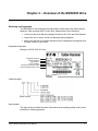
Table of Contents
Safety Instructions ...............................................................................................................i
Safety Messages ...............................................................................................................................................i
Definitions and Symbols ................................................................................................................................i
Hazardous High Voltage....................................................................................................................................i
Warnings, Notes and Cautions......................................................................................................................... ii
Table of Contents ..............................................................................................................vii
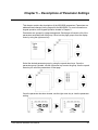
Chapter 1
– Introduction ............................................................................................. 1-1
Chapter 2
– Overview of the MVX9000 Drive ............................................................. 2-1
Receiving and Inspection ............................................................................................................................. 2-1
Digital Keypad Operation ............................................................................................................................. 2-3
Chapter 3
– Storage and Installation .......................................................................... 3-1
Storage ......................................................................................................................................................... 3-1
Environment ................................................................................................................................................. 3-1
Mounting Area .............................................................................................................................................. 3-2
Wiring............................................................................................................................................................ 3-3
Applicable Codes.......................................................................................................................................... 3-3
Basic Wiring Diagram ................................................................................................................................... 3-4
External Wiring.......................................................................................................................................... 3-5
Control Terminal Wiring (Factory Settings) .................................................................................................. 3-6
Main Circuit Wiring ....................................................................................................................................... 3-7
Motor Operation Precautions ....................................................................................................................... 3-9
Chapter 4
– Start-up Procedures ................................................................................ 4-1
Step-by-Step Installation .............................................................................................................................. 4-1
Mounting Location..................................................................................................................................... 4-1
Inverter Mounting ...................................................................................................................................... 4-3
Wiring Preparation .................................................................................................................................... 4-4
Wiring the Inverter to Incoming Power...................................................................................................... 4-8
Wiring the Motor to the Inverter Output .................................................................................................... 4-8
Powerup Test............................................................................................................................................ 4-9
Chapter 5
– Descriptions of Parameter Settings....................................................... 5-1
Parameter Groups ........................................................................................................................................ 5-3
Cutler-Hammer MVX9000 User Manual
vii
Table of Contents
Group 20 — Basic Grouping (Quick Start) ................................................................................................... 5-4
Group 30 — Inputs........................................................................................................................................ 5-6
Group 40 — Outputs...................................................................................................................................5-24
Group 50 — AC Drive Control ....................................................................................................................5-28
Group 60 — Motor Control..........................................................................................................................5-45
Group 70 — Protective Functions...............................................................................................................5-49
Group 80 — Display....................................................................................................................................5-54
Group 90 — Communications.....................................................................................................................5-58
Chapter 6
– Maintenance and Inspection................................................................... 6-1
Periodic Inspection........................................................................................................................................ 6-1
Periodic Maintenance ................................................................................................................................... 6-1
Chapter 7
– Troubleshooting and Fault Information ................................................. 7-1
Common Problems and Solutions ................................................................................................................ 7-1
Warning codes .............................................................................................................................................. 7-4
MVX9000 Parameter Listing .........................................................................................................................B-1
20 — BASIC GROUPING (Quick Start) ....................................................................................................B-1
30 — INPUTS............................................................................................................................................B-2
40 — OUTPUTS........................................................................................................................................B-4
50 — DRIVE CONTROL ...........................................................................................................................B-5
60 — MOTOR CONTROL.........................................................................................................................B-8
70 — PROTECTIVE..................................................................................................................................B-9
80 — KEYPAD/DISPLAY ....................................................................................................................... B-10
90 — COMMUNICATION PARAMETERS............................................................................................. B-12
Fuse Specification Chart.............................................................................................................................. C-1
Wiring Table ................................................................................................................................................. C-2
All Braking Resistors & Braking Units Used in AC Drives ........................................................................... C-3
EMI Filter Cross Reference.......................................................................................................................... C-4
EMI Filters .................................................................................................................................................... C-5
Din Rail Adapter (P/N: MVXDR) .................................................................................................................. C-9
Remote Kit (P/N: MVXRM) ........................................................................................................................ C-10
Extension Input/Output (P/N: MVXEIO)..................................................................................................... C-10
viii
Cutler-Hammer MVX9000 User Manual
Chapter 1 – Introduction
This chapter describes the purpose and contents of this manual and the intended
audience. This chapter also explains conventions used in this manual and lists related
publications.
How to Use This Manual
The purpose of this manual is to provide you with information necessary to install, set
parameters, troubleshoot, and maintain the AC motor drives. To guarantee safe
operation of the equipment, read the safety guidelines at the beginning of this manual
before connecting power to the AC motor drives. Keep this operating manual handy
and distribute to all users for reference.
Chapter 1 – Introduction is the chapter you are reading now.
Chapter 2 – Overview of the MVX9000 Drive describes receiving and inspection
procedures and provides an introduction to digital keypad operation.
Chapter 3 – Storage and Installation describes planning for drive installation and drive
mounting. This chapter also includes requirements and connections for wiring.
Chapter 4 – Start-up Procedures provides a detailed explanation of digital keypad
operation.
Chapter 5 – Descriptions of Parameter Setting provides detailed explanations for all
parameter settings.
Chapter 6 – Maintenance and Inspection describes maintenance procedures.
Chapter 7 – Troubleshooting and Fault Information lists the fault displays,
descriptions, and corrective actions.
Appendix A – Technical Data lists standard specifications.
Appendix B – Summary of Parameter Settings provides brief descriptions of all
parameters and their settings.
Appendix C – Accessories provides information about circuit breakers, fuses, braking
resistors, and other accessories for the Cutler-Hammer MVX9000 Drives.
Appendix D – Dimensions displays keypad and drive dimensions.
Appendix E – is a Declaration of Conformity.
Cutler-Hammer MVX9000 User Manual
1-1
Chapter 1 – Introduction
Intended Audience
The audience for this manual has:
Knowledge of standard electrical wiring practices, electronic components, and
electrical schematic symbols.
The audience for this manual will install, start-up, and service the Cutler-Hammer
MVX9000 Drives.
Conventions Used in this Manual
Listed below are terms and language conventions used in this manual. These terms
and conventions are defined here to help you understand their meanings and
applications throughout this manual.
Digital Keypad Display
The Digital Keypad display is an LED readout of drive parameter selections and drive
operation status. Letters or numbers appear in the display according to which keys you
press.
Digital Keypad Keys
Digital Keypad keys are flat, labeled, push-button-type devices that allow you to select
drive parameters, and monitor drive operation.
Parameter
A parameter is selected through the Digital Keypad. Parameters in this manual are
expressed as Parameter Group Number, a decimal (.), and a Parameter number.
Press
Press a key on the Digital Keypad Control Panel to select a parameter. Refer to
Chapter 2 – Overview of the MVX9000 Drive, Digital Keypad.
1-2
Cutler-Hammer MVX9000 User Manual
Chapter 1 – Introduction
Warranty and Liability Information
CUTLER-HAMMER warrants the product delivered in the CUTLER-HAMMER
shipping package to be free from defects in material and workmanship, under normal
use and service, for twenty four (24) months from date of manufacturing. Products
that fail during this period will be repaired or replaced at CUTLER-HAMMER’s
discretion, with the same or a functionally equivalent product, provided the original
purchaser (A) returns the failed product, and (B) provides proof of original date of
purchase. This warranty does not apply, in the judgment of CUTLER-HAMMER, to
damage caused during shipment, handling, storage, or accidental misuse. The
original purchaser of the product must obtain a Return Material Authorization (RMA)
number from CUTLER-HAMMER prior to returning any defective product. (When
purchased through an Authorized Distributor, the Distributor should supply an RMA
number to their customer.)
The maximum liability of this warranty is limited to the purchase price of the product. In
no event, regardless of cause, shall CUTLER-HAMMER be liable (a) for penalties or
penalty clauses of any description, or (b) for certification not otherwise specifically
provided herein and/or indemnification of purchaser or others for costs, damages or
expenses, each arising out of or related to the product or services of any order or (c)
for any damages resulting from loss of profits, use of products or for any incidental
indirect or consequential damages, even if advised of the possibility of such damages.
Related Publications
Brochure (Publication Number: BR04002001E)
Technical Document (Publication Number: TD04002001E)
Manual (Publication Number: 5011614100)
Contact Name, Number:
Eaton Corporation
Cutler-Hammer Business Unit
1000 Cherrington Parkway
Moon Township, PA 15108-4312
Tel: 1-800-525-2000
www.cutler-hammer.eaton.com
Cutler-Hammer MVX9000 User Manual
1-3
Chapter 1 – Introduction
This page intentionally left blank.
1-4
Cutler-Hammer MVX9000 User Manual
Chapter 2 – Overview of the MVX9000 Drive
Receiving and Inspection
This MVX9000 AC drive has gone through quality control tests at the factory before
shipment. After receiving the AC motor drive, please check for the following:
Check to make sure that the package includes an AC drive and User Manual.
Inspect the unit to insure it was not damaged during shipment.
Make sure that the part number indicated on the nameplate corresponds with
the part number of your order.
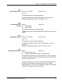
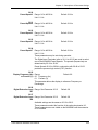
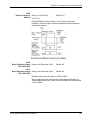
Nameplate Information
Example of 0.5HP 230V AC drive
Catalog Number
Style Number
Input Spec.
Output Spec.
Output frequency Rang
Serial Number Bar Code
XXXXXX
Catalog Number
Style Number
The style number contains the same information as the catalog number, and is used
internally for ordering purposes.
Cutler-Hammer MVX9000 User Manual
2-1
Chapter 2 – Overview of the MVX9000 Drive
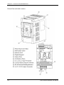
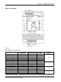
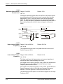
External Parts and Label Locations
2-2
Cutler-Hammer MVX9000 User Manual
Chapter 2 – Overview of the MVX9000 Drive
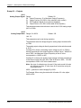
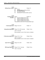
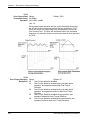
Digital Keypad Operation
The digital keypad includes the display panel and the keypad. The display panel
provides the parameter display and shows the operation status of the AC drive. The
keypad provides programming and control interface.
Description of Digital Keypad
MVX9000 KEYPAD
LED Indicators
Lamp lights during Run
Stop, Fwd, Rev operations
LED Indicators
Lamp Lights to indicated
Frequency Input, Hz Output,
Amps and User Defined units
F
RUN
STOP
FWD
REV
H
LED Display
Indicates motor and
drive parameter
A
U
Potentiometer
For setting input speed
command
START Key
Start Command
START
Up, Down, and Right/Left Keys
Scrolls display, enter/exit
Parameter mode, change
parameter settings
+
STOP
RESET
ENTER
STOP/RESET
Stop command and
reset the drive after a
fault occurs
ENTER Key
Enter key used in
Parameter mode to enter
and change values
Explanation of the LED Indicators
LED Displays
RUN
STOP
FWD
REV
Red lamp lights during REV operation.
Red lamp lights during FWD operation.
Red lamp lights by pressing STOP.
Red lamp lights by pressing RUN.
F
———
Lamp lights to indicate input frequency reference
H
———
Lamp lights to indicate output Hz
A
———
Lamp lights to indicate output amps
U
———
Lamp lights to indicate user defined units
Cutler-Hammer MVX9000 User Manual
2-3
Chapter 2 – Overview of the MVX9000 Drive
Table 2-1 Keypad Operators
Start
This button operates as Start button for normal operation.
Motor START from the panel; active control place has to be selected at ‘Panel’
Enter
This button in the parameter edit mode is used to enter the programming mode and enter
the parameter selection.
used for parameter edit confirmation, acceptance (confirmation) of the edited
parameter value with exit from parameter edit mode
Stop / Reset
This button has two integrated operations. The button operates as Stop button for normal
operation. In the parameter edit mode it is used to cancel previous action and back-up one
step, and in fault mode it is used to reset the fault.
Stop
motor STOP from the panel; active control place has to be selected at ‘Panel’
Reset
used for active fault resetting
- fault history is reset if ENTER is pressed on the ‘Fault History’ menu group in ‘Main
Menu’ or
- if ENTER is pressed while in the ‘Fault History’ menu
in programming mode press RESET key to cancel previous action and back up one
step
Left Arrow
navigation button, movement to left
in display mode, enter parameter group mode
in parameter edit mode, exits mode, backs up one step
cancels edited parameter (exit from a parameter edit mode)
Right Arrow
navigation button, movement to right
enter parameter group mode
enter parameter mode from group mode
Up and Down Arrows
move either up or down the group list in order to select the desired group menu.
move either up or down the parameter list in order to select the desired parameter in
the group.
increasing/decreasing of reference value on the keyboard (when selected).
Speed POT
increase/decrease reference value on the keypad (when selected)
2-4
Cutler-Hammer MVX9000 User Manual
Chapter 2 – Overview of the MVX9000 Drive
Explanation of Display Messages
Table 2-2
Displayed Message
Descriptions
The AC drive Input Frequency Reference.
The Actual Operation Frequency at the output terminals T1, T2, and T3.
The output current present at the output terminals T1, T2, and T3.
The value of the user defined units.
The output voltage present at the output terminals T1, T2, and T3.
The temperature of the unit.
The AC drive forward run status.
The AC drive reverse run status.
Parameter group selection.
The specific parameter selection.
“End” displays for approximately 1 second if input has been accepted. After a parameter
value has been set, the new value is automatically stored in memory.
“Err” displays, if the input is invalid.
Cutler-Hammer MVX9000 User Manual
2-5
Chapter 2 – Overview of the MVX9000 Drive
This page intentionally left blank.
2-6
Cutler-Hammer MVX9000 User Manual
Chapter 3 – Storage and Installation
Storage
The AC drive should be stored in the shipping carton before installation. In order to
retain the warranty coverage, the AC drive should be stored properly when it is not to
be used for an extended period of time. Some storage suggestions are:
Store in a clean and dry location free from direct sunlight or corrosive fumes.
Store within an ambient temperature range of -20 °C to +60 °C.
Store within a relative humidity range of 0% to 90% and non-condensing
environment.
Store within an air pressure range of 86 kPA to 106kPA.
Environment
Operation
Air Temperature:
1/2 HP-5HP
7.5 HP-10HP
Relative Humidity:
Atmosphere pressure:
Installation Site Altitude:
Vibration:
-10°C to +50°C (14°F to 122°F),
-10°C to +40°C (14°F to 104°F)
0% to 90%, no condensation allowed
86 to 106 kPa
below 1000m
Maximum 9.80 m/s2 (1G) at less than 20Hz
Maximum 5.88 m/s2 (0.6G) at 20Hz to 50Hz
Storage
Temperature:
Relative Humidity:
Atmosphere pressure:
-20°C to +60°C (-4°F to 140°F)
Less than 90%, no condensation allowed
86 to 106
Temperature:
Relative Humidity:
Atmosphere pressure:
Vibration:
-20°C to +60°C (-4°F to 140°F)
Less than 90%, no condensation allowed
86 to 106 kPa
Maximum 9.80 m/s2 (1G) at less than 20Hz,
Maximum 5.88 m/s2 (0.6G) at 20Hz to 50Hz
Transportation
Pollution Degree
UL Type 0,
Pollution Degree 2:
Relative Humidity:
Atmosphere pressure:
Cutler-Hammer MVX9000 User Manual
good for a factory type environment
Less than 90%, no condensation allowed
86 to 106
3-1
Chapter 3 – Storage and Installation
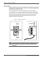
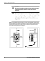
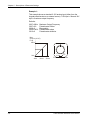
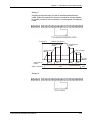
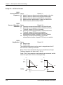
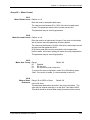
Mounting Area
Improper installation of the AC drive will greatly reduce its life. Be sure to observe the
following precautions when selecting a mounting location. Failure to observe these
precautions may void the warranty!
Do not mount the AC drive near heat-radiating elements or in direct sunlight.
Do not install the AC drive in a place subjected to high temperature, high humidity,
excessive vibration, corrosive gases or liquids, or airborne dust or metallic particles.
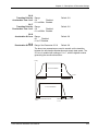
Mount the AC drive vertically and do not restrict the air flow to the heat sink fins.
The AC drive generates heat. Allow sufficient space around the unit for heat
dissipation as shown in the figure below:
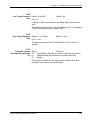
Figure 3-1 Mounting in an Enclosure
Air Flow
F
RUN
STOP
FWD
REV
H
A
U
START
+
STOP
RESET
ENTER
When mounting in an enclosure, allow for the recommended free
space. Failure to allow adequate air flow may result in drive over
temperature.
3-2
Cutler-Hammer MVX9000 User Manual
Chapter 3 – Storage and Installation
Wiring
DANGER!
Hazardous Voltage
Before opening the AC drive covers:
Disconnect all power to the AC drive.
Wait five minutes for DC bus capacitors discharge.
Any Electrical or mechanical modification to this equipment without prior
written consent of Eaton Cutler-Hammer will void all warranties and may result
in a safety hazard in addition to voiding the UL listing.
Short Circuit Withstand:
Suitable for use on a circuit capable of delivering not more than 5,000 rms symmetrical
amperes; for all 460V Models, the maximum is 480 Volts; for all 230V Models, the
maximum is 240 Volts.
Applicable Codes
All MVX9000 AC drives are Underwriters Laboratories, Inc. (UL) and Canadian
Underwriters Laboratories (cUL) listed, and therefore comply with the requirements of
the National Electrical Code (NEC) and the Canadian Electrical Code (CEC).
Installation intended to meet the UL and cUL requirements must follow the instructions
provided in “Wiring Notes” as a minimum standard. Follow all local codes that exceed
UL and cUL requirements. Refer to the technical data label affixed to the AC drive and
the motor nameplate for electrical data.
The "Line Fuse Specification" in Appendix C, lists the recommended fuse part number
for each MVX9000 part number. These fuses (or equivalent) must be used on all
installations where compliance with U.L. standards is required.
According to the Low Voltage Directive 73/23/EEC and the Amendment Directive
93/68/EEC Digital Keypad, the following AC Motor Drives, MVXF50A0-2,
MVX001A0-2, MVX002A0-2, MVX003A0-2, MVX005A0-2, MVX007A0-2,
MVX001A0-4, MVX002A0-4, MVX003A0-4, MVX005A0-4, MVX007A0-4,
MVX010A0-4, is herewith confirmed to comply with the requirements set out in the
Council Directive 73/23/EEC for electrical equipment used within certain voltage limits
and the Amendment Directive 93/68/EEC. For the evaluation of the compliance with
this Directive, the following standard was applied: EN 50178.
According to the Electromagnetic Compatibility 89/336/EEC and the Amendment
Directive 93/68/EEC, the following equipment, AC Motor Drive, MVXF50A0-2,
MVX001A0-2, MVX002A0-2, MVX003A0-2, MVX005A0-2, MVX007A0-2,
MVX001A0-4, MVX002A0-4, MVX003A0-4, MVX005A0-4, MVX007A0-4,
MVX010A0-4, is herewith confirmed to comply with the requirements set out in the
Council Directive 89/336/EEC for electromagnetic compatibility and the Amendment
Directive 93/68/EEC. For the evaluation of the compliance with this Directive, the
following standard was applied: EN61800-3, EN55011, EN50081-2, EN50082-2,
EN61000-4-2, EN61000-4-3, EN61000-4-4, EN61000-4-5, EN61000-4-6,
EN61000-4-8.
Cutler-Hammer MVX9000 User Manual
3-3
Chapter 3 – Storage and Installation
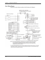
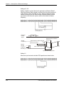
Basic Wiring Diagram
Users must connect wiring according to the following circuit diagram.
3-4
Cutler-Hammer MVX9000 User Manual
Chapter 3 – Storage and Installation
External Wiring
Items
Input Power
Fuse
Explanations
Please follow the specific power supply
requirement shown in Appendix A.
Please check the Fuse Specification table in
Appendix C for proper fuse selection.
Magnetic
contactor
(Optional)
Please do not use a Magnetic contactor as the
ON/OFF switch of the AC drive, this will reduce
the operating life of the AC drive. The contactor
should only be used as a safety device for
disconnecting power to the drive.
Line/Load
Reactor
(Optional)
To improve the power factor. An AC Reactor may
be necessary when capacity is above 1000kVA,
and the wiring distance is within 10m.
EMI filter
(Optional)
Used to reduce the electromagnetic interference.
Braking
Resistor
(Optional)
Used to reduce stopping time of the motor. Please
refer to the Breaking Resistor table in Appendix C
for specific Braking Resistors.
Note: Please refer to Appendix C for more details on the Circuit Breaker and Fuse
Specification tables.
Cutler-Hammer MVX9000 User Manual
3-5
Chapter 3 – Storage and Installation
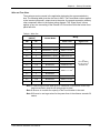
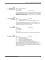
Control Terminal Wiring (Factory Settings)
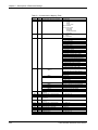
RO3 RO2 RO1
DI1 DI2 DI3 DI4 DI5 DI6 COM AO+ AI1 +10V AI2 COM DO1 DOC
Factory setting:
inverter running
N.O. Relay output
Factory Setting
N.C. Relay output
4~20mA
Run/Stop
Reverse/Forward
Preset speed 1
Preset speed 2
Preset speed 3
Reset
Digital output
Bias
Potentiometer
Full scale voltmeter
0 to 10 VDC
Factory setting:
output frequency
Wire type: 75℃, copper only.
Note: For Wire Gauge and Torque tightening specifications, please refer to the
next page.
Table 3-1
Terminal symbols
RO1 - RO2
Terminal name
Digital Output Relay
RO3 - RO2
Digital Output Relay
D01 - DCM
RJ - 12
+10V - COM
AI1 - COM
AI2 - COM
AO+ - COM
DI1 - COM
DI2 - COM
to
Digital photocouple output
Serial communication port
DI6 - GND
Analog voltage input
Analog current input
Analog frequency/current meter
Digital input 1
Digital input 2
to
Remarks
Refer to 40.04 Relay output contact
RO1-RO2 (N.C. Contact)
RO3-RO2 (N.O. Contact)
Refer to 40.03
RS-485 serial communication interface
Power Supply (+10 V)
0 to +10 V Input
0-20mA or 4 to 20mA Input
0 to +10 V Output
Refer to 30.11
Digital input 6
Note: Use twisted-shielded, twisted-pair or shielded-lead wires for the control
signal wiring. It is recommended to run all signal wiring in a separate steel
conduit. The shield wire should only be connected at the drive. Do not
connect shield wire on both ends.
3-6
Cutler-Hammer MVX9000 User Manual
Chapter 3 – Storage and Installation
Main Circuit Wiring
Table 3-2
Wire Type: 75°C Copper Only
Catalog Number
MVXF50A0-2 (1 phase)
MVXF50A0-2 (3 phase)
MVX001A0-2 (1 phase)
MVX001A0-2 (3 phase)
MVX002A0-2 (1 phase)
MVX002A0-2 (3 phase)
MVX003A0-2 (1 phase)
MVX003A0-2 (3 phase)
MVX005A0-2
MVX007A0-2
MVX001A0-4
MVX002A0-4
MVX003A0-4
MVX005A0-4
MVX007A0-4
MVX010A0-4
Voltage,
Horsepower
240 VAC, 0.5 Hp
240 VAC, 0.5 Hp
240 VAC, 1 Hp
240 VAC, 1 Hp
240 VAC, 2 Hp
240 VAC, 2 Hp
240 VAC, 3 Hp
240 VAC, 3 Hp
240 VAC, 5 Hp
240 VAC, 7.5 Hp
480 VAC, 1 Hp
480 VAC, 2 Hp
480 VAC, 3 Hp
480 VAC, 5 Hp
480 VAC, 7.5 Hp
480 VAC, 10 Hp
Cutler-Hammer MVX9000 User Manual
Max. Current(A)
(Input/Output)
6.3
3.2
11.5
6.3
15.7
9
27
15
19.6
28
4.2
5.7
6
8.5
14
23
Wire Gauge
(AWG)
12-14
12-14
12-14
12-14
12
12-14
8
8-12
8-10
8
12-14
12-14
12-14
8-14
8-12
8-10
Torque Rating
(kgf-cm)
14
15
14
15
3-7
Chapter 3 – Storage and Installation
Wiring Notes
Please read prior to Installation
CAUTION!
Do not connect the AC power to the T1, T2, T3
terminals, it will damage the AC drive.
WARNING!
Make sure that all screws are tightened to the proper
torque rating shown in Table 3-2.
During installation, follow all local electrical, construction, and
safety codes for the country in which the drive is installed.
Make sure that the appropriate protective devices (circuit breaker
or fuses) are connected between the power supply and AC drive.
Make sure that the leads are connected correctly and the AC drive
is properly grounded.
Use ground leads that comply with AWG/MCM standards and
keep them as short as possible.
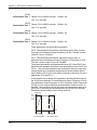
Multiple MVX9000 units can be installed in one location. All the
units should be grounded directly to a common ground terminal.
The MVX9000 ground terminals may also be connected in parallel,
as shown in the figure below. Make sure there are no ground
loops.
Yes
Yes
No
Forward
running
When the AC drive output terminals U/T1, V/T2, and W/T3 are
connected to the motor terminals T1, T2, and T3, respectively, the
motor will rotate counterclockwise (as viewed from the shaft ends
of the motor) when a forward operation command is received. To
reverse the direction of motor rotation, switch over any of the two
motor leads.
Make sure that the power source is capable of supplying the
correct voltage and required current to the AC drive.
Do not attach or remove wiring when power is applied to the AC
drive.
Do not inspect components unless the inside “POWER” lamp has
turned off.
3-8
Cutler-Hammer MVX9000 User Manual
Chapter 3 – Storage and Installation
Do not monitor the signals on the circuit board while the AC drive
is in operation.
For the single-phase rated AC drives, the AC power can be
connected to any two of the three input terminals R/L1, S/L2, T/L3.
Note: This drive is not intended for the use with single-phase
motors.
Route the power and control wires separately, or at a 90 degree
angle to each other.
If a filter is required for reducing EMI (Electro Magnetic
Interference), install it as close as possible to the AC drive. EMI
can also be reduced by lowering the Carrier Frequency.
If the AC drive is installed in the place where a load reactor is
needed, install the filter close to U/T1, V/T2, W/T3 side of AC drive.
Do not use a Capacitor or L-C Filter (Inductance-Capacitance) or
R-C Filter (Resistance-Capacitance), unless approved by
Cutler-Hammer.
When using a GFCI (Ground Fault Circuit Interrupt), select a
current sensor with sensitivity of 200mA, and not less than
0.1-second detection to avoid nuisance tripping.
Motor Operation Precautions
When using the AC drive to operate a standard 3-phase induction
motor, notice that the energy loss is greater than for an inverter
duty motor.
Avoid running a standard induction motor at low speed. Under
these conditions, the motor temperature may rise above the motor
rating due to limited airflow produced by the motor’s fan.
When the standard motor operates at low speed, the output load
must be decreased.
If 100% output torque is desired at low speed, it may be necessary
to use a special “inverter-duty” rated motor.
Cutler-Hammer MVX9000 User Manual
3-9
Chapter 3 – Storage and Installation
This page intentionally left blank.
3-10
Cutler-Hammer MVX9000 User Manual
Chapter 4 – Start-up Procedures
This chapter will explain the installation of the MVX9000 Microdrive. Be sure to read
and follow all instructions for a successful installation.
WARNING!
This equipment should be installed, adjusted, and serviced by
qualified electrical maintenance personnel familiar with the
construction and operation of the equipment and the hazards
involved. Failure to observe this precaution could result in
bodily injury.
Step-by-Step Installation
1. Read all instructions and warnings associated with mounting the MVX9000.
2. Select a suitable mounting location.
3. Check the inverter mounting dimensions for footprint and mounting hole locations.
4. Connect the wiring for the inverter input.
5. Connect the wiring to the motor.
6. Perform a power-up test.
7. Make observations and re-check the installation.
Mounting Location
Step 1: Study the following caution messages associated with mounting the inverter.
CAUTION!
Be sure to install the unit on flame-resistant material such as a
steel plate. Otherwise, there is the danger of fire.
CAUTION!
Be sure to install the unit on a perpendicular wall which is not
subject to vibration. Otherwise, it may fall and cause injury to
personnel.
CAUTION!
Be sure not to let the foreign matter enter vent openings in the
inverter housing, such as wire clippings, spatter from welding,
metal shavings, dust, etc. Otherwise, there is the danger of fire.
Cutler-Hammer MVX9000 User Manual
4-1
Chapter 4 – Start-up Procedures
CAUTION!
Be sure not to install or operate an inverter which is damaged
or has missing parts. Otherwise, it may cause injury to
personnel.
CAUTION!
Be sure to install the inverter in a well-ventilated room which
does not have direct exposure to sunlight, a tendency for high
temperature, high humidity or dew condensation, high levels of
dust, corrosive gas, explosive gas, inflammable gas,
grinding-fluid mist, salt damage, etc. Otherwise, there is the
danger of fire.
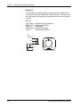
Step 2: The installation should be made on a solid, non-flammable, vertical surface
that is a relatively clean and dry environment. In order to ensure enough room for air
circulation around the inverter to aid in cooling, maintain the specified clearance
around the inverter specified in the diagram.
Air Flow
F
RUN
STOP
FWD
REV
H
A
U
START
+
STOP
RESET
ENTER
4-2
Cutler-Hammer MVX9000 User Manual
Chapter 4 – Start-up Procedures
Please observe this checklist while mounting the inverter:
The ambient temperature must be in the range of –10 to 50ºC (1/2 to 5hp).
The ambient temperature must be in the range of –10 to 40ºC (7.5 to 10hp). If
the range will be up to 50ºC, set the carrier frequency to 2.1 kHz or less and
derate the output current to 80% or less. Chapter 5 covers how to change
parameters such as the carrier frequency.
Keep any other heat-producing equipment as far away from the inverter as
possible.
When installing the inverter in an enclosure, maintain the clearance around the
inverter and verify that its ambient temperature is within specification when the
enclosure door is closed.
Do not open the main front panel door at any time during operation.
Step 3: Before proceeding to the wiring section, temporarily cover the inverter’s
ventilation openings. Paper and masking tape is all that is needed to do this. This will
prevent harmful debris such as wire clippings and metal shavings from entering the
inverter during installation.
Inverter Mounting
Step 4: Locate the applicable drawing in the Appendix for the inverter unit.
Dimensions are given in inches (millimeters) format.
Note: Some inverter housings require two mounting screws, while others require
four. Be sure to use lock washers or other means to ensure screws do not
loosen due to vibration.
Cutler-Hammer MVX9000 User Manual
4-3
Chapter 4 – Start-up Procedures
Wiring Preparation
Step 5: It is very important to perform the wiring steps carefully and correctly. Before
proceeding, please study the caution and warning messages below.
WARNING!
“Use 75℃ Cu wire only” or equivalent.
WARNING!
“Suitable for use on a circuit capable of delivering not more
than 5,000 rms symmetrical amperes, 240 V maximum.” For
models with suffix B.
WARNING!
“Suitable for use on a circuit capable of delivering not more
than 5,000 rms symmetrical amperes, 480 V maximum.” For
models with suffix C.
HIGH VOLTAGE!
Be sure to ground the unit. Otherwise, there is danger of
electric shock and/or fire.
HIGH VOLTAGE!
Wiring work shall be carried out only by qualified personnel.
Otherwise, there is a danger of electric shock or fire.
4-4
Cutler-Hammer MVX9000 User Manual
Chapter 4 – Start-up Procedures
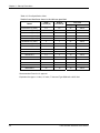
Wire and Fuse Sizes
The maximum motor currents in the application determine the recommended wire
size. The following table gives the wire size in AWG. The Power/Motor column applies
to the inverter input power, output wires to the motor, the ground connection, and any
other component shown in the system wiring diagram. The “Signal Lines” column
applies to any wire connecting to the External I/O Connection inside the bottom front
panel half-door.
Table 4-1 Wire Size
Motor Output
(kW/HP)
Wiring
Inverter Model
kW
HP
Power Lines
0.4
1/2
MVXF50A0-2
AWG14 / 2.1 mm2
.75
1
MVX001A0-2
AWG14 / 2.1 mm2
1.5
2
MVX002A0-2 (1 phase)
AWG12 / 3.3 mm2
1.5
2
MVX002A0-2 (3 phase)
AWG14 / 2.1 mm2
2.2
3
MVX003A0-2 (1 phase)
AWG 8 / 8.4 mm2
2.2
3
MVX003A0-2 (3 phase)
AWG12 / 3.3 mm2
3.7
5
MVX005A0-2
AWG10 / 5.3 mm2
5.5
7-1/2
MVX007A0-2
AWG8 / 8.4 mm2
0.75
1
MVX001A0-4
1.5
2
MVX002A0-4
2.2
3
MVX003A0-4
4.0
5
MVX005A0-4
AWG14 / 2.1 mm2
5.5
7-1/2
MVX007A0-4
AWG12 / 3.3 mm2
7.5
10
MVX010A0-4
AWG10 / 5.3 mm2
AWG14 / 2.1 mm
Signal Lines
(*)
18 to 20 AWG /
2
0.14 to 0.75 mm
shielded wire
2
Note 1: Field wiring must be made by a UL-listed and CSA-certified closed-loop
terminal connector sized for the wire gauge involved.
Note 2: Be sure to consider the capacity of the circuit breaker to be used.
Note 3: Be sure to use larger wires for the power lines in the distance exceeds 20
meters.
Cutler-Hammer MVX9000 User Manual
4-5
Chapter 4 – Start-up Procedures
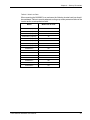
Table 4-2 Fuse Specification Chart
Smaller fuses than those shown in the table are permitted.
Line Fuse
Model
Input
Current (A)
Output
Current (A)
I (A)
Bussmann P/N
MVXF50A0-2 (1 phase)
6.3
2.5
25
JJN-25
MVXF50A0-2 (3 phase)
3.2
2.5
10
JJN-10
MVX001A0-2 (1 phase)
11.5
5
45
JJN-45
MVX001A0-2 (3 phase)
6.3
5
20
JJN-20
MVX002A0-2 (1 phase)
15.7
7
60
JJN-60
MVX002A0-2 (3 phase)
9
7
25
JJN-25
MVX003A0-2 (1 phase)
27
10
100
JJN-100
MVX003A0-2 (3 phase)
15
10
40
JJN-40
MVX005A0-2
19.6
17
60
JJN-60
MVX007A0-2
28
25
100
JJN-100
MVX001A0-4
4.2
3
10
JJS-10
MVX002A0-4
5.7
4
15
JJS-15
MVX003A0-4
6
5
20
JJS-20
MVX005A0-4
8.5
8.2
30
JJS-30
MVX007A0-4
14
13
50
JJS-50
MVX010A0-4
23
18
70
JJS-70
Recommended Fuses for UL approval
Equivalent fuse types = J class, CC class, T class and Type BS88 with a 600V limit.
4-6
Cutler-Hammer MVX9000 User Manual
Chapter 4 – Start-up Procedures
Table 4-3 Heat Loss Data
When mounting the MVX9000 in an enclosure the following inverter heat loss should
be considered. Failure to provide adequate cooling may cause premature failure of the
inverter and/or overtemperature faults.
Model
Watts Lost at 9 kHz
MVXF50A0-2 (1 phase)
20
MVXF50A0-2 (3 phase)
20
MVX001A0-2 (1 phase)
38
MVX001A0-2 (3 phase)
38
MVX002A0-2 (1 phase)
75
MVX002A0-2 (3 phase)
75
MVX003A0-2 (1 phase)
110
MVX003A0-2 (3 phase)
110
MVX005A0-2
185
MVX007A0-2
275
MVX001A0-4
38
MVX002A0-4
75
MVX003A0-4
110
MVX005A0-4
185
MVX007A0-4
275
MVX010A0-4
375
Cutler-Hammer MVX9000 User Manual
4-7
Chapter 4 – Start-up Procedures
Wiring the Inverter to Incoming Power
Step 6: In this step, connect the wiring to the input of the inverter. First determine
whether the inverter model requires three-phase power only, or if it can accept either
singe-phase or three-phase power. All models have the same power connector
(Ground). Refer to the specifications label (on
terminals labeled L1, L2, L3 and
the side of the inverter) for the acceptable power source types! For inverters
which can accept single-phase power, use terminals L1 and L2.
CAUTION!
Be sure that the input voltage matches the inverter
specifications:
• Single/Three phase 200 to 240 V 50/60 Hz (up to 2.2k/W)
• Three phase 200 to 230 V 50/60 Hz (above 2.2kW)
• Three phase 380 to 460 V 50/60 Hz
CAUTION!
Be sure not to connect an AC power
supply to the output terminals.
Otherwise, there is the danger of injury
and/or fire.
Note:
L1, L2, L3: Three-phase 200 to 230V 50/60 Hz
Three-phase 380 to 460V 50/60 Hz
Any two inputs: Single-phase 200 to 240V 50/60 Hz
Wiring the Motor to the Inverter Output
Step 7: Connect the three phase AC induction motor to the output of the inverter. The
motor must be a three phase induction motor. It should also come with a chassis
ground lug. If the motor does not have three power input leads, stop the installation
and verify the motor type. Other guidelines for wiring the motor include:
Use an inverter-grade motor for maximum motor life (1600 V insulation).
For standard motors, use the AC reactor accessory if the wiring between the
inverter and motor exceeds 30 feet (10 meters) in length.
Connect the motor to the terminals indicated on the inverter. The terminals are labeled
T1, T2, and T3. Connect the chassis ground lug on the inverter. The motor chassis
ground must also connect to the same point. Use a star ground (single point)
arrangement, and never daisy-chain the grounds (point-to-point).
Use the same wire gauge on the motor and chassis ground wiring as you used on the
power input wiring in the previous step. After completing the wiring:
Check all wire connections both at the inverter and motor to make sure they
are secure.
Close all access doors.
Remove any covering placed on the inverter ventilation openings.
4-8
Cutler-Hammer MVX9000 User Manual
Chapter 4 – Start-up Procedures
Powerup Test
Step 8: After wiring the inverter and motor, perform a powerup test. The procedure
that follows is designed for the first-time use of the drive. Verify the following conditions
before conducting the powerup test:
•
The previous steps in this chapter have been followed.
•
The inverter is new, and securely mounted to a non-flammable vertical surface.
•
The inverter is connected to a power source and motor.
•
No additional wiring of the inverter connectors or terminals has been done.
•
The power supply is reliable, and the motor is a known working unit.
•
The motor is mounted, and is not connected to any load.
The following instructions apply to the powerup test, or to any time the inverter is
powered and operating. Please study the following instructions and messages before
proceeding with the powerup test.
1. The power supply must have fusing suitable for the load. Check the fuse size chart
presented in Step 5 if necessary.
2. Be sure you have access to a disconnect switch for the drive input power if
necessary. However, do not turn off power to the inverter during its operation
unless it is an emergency.
3. Turn the inverter’s front panel potentiometer to the MIN position (fully
counterclockwise).
CAUTION!
The operation of the inverter can be easily changed from low
speed to high speed. Be sure to check the capability and
limitations of the motor and machine before operating the
inverter. Otherwise, there is the danger of injury.
CAUTION!
If you operate a motor at a frequency higher than the inverter
standard default setting (50Hz/60Hz), be sure to check the
motor and machine specifications with the respective
manufacturer. Only operate the motor at elevated frequencies
after getting their approval. Otherwise, there is the danger of
equipment damage.
Cutler-Hammer MVX9000 User Manual
4-9
Chapter 4 – Start-up Procedures
Powering the Inverter
If you have followed all the steps, cautions and warnings up to this point, you’re ready
to apply power. After doing so, the following events should occur:
•
The numeric (7-segment) LEDs will illuminate.
•
The Hz, Stop and Fwd LEDs will illuminate.
If the motor starts running unexpectedly or any other problem occurs, press the STOP
button. Only if necessary should you remove power to the inverter as a remedy.
Note: If the inverter has been previously powered and programmed, the LEDs
(other than the POWER LED) may illuminate differently than as indicated
above. If necessary, you can initialize all parameters to the factory default
settings. See the initialization instructions in the Programming section.
4-10
Cutler-Hammer MVX9000 User Manual
Chapter 5 – Descriptions of Parameter Settings
This chapter contains the descriptions of the MVX9000 parameters. Parameters are
addressed and changed via the keypad for the MVX9000. For more information on
keypad operation, see Keypad Operation located in Chapter 2.
Parameters are grouped in a page arrangement. Each page will contain a list of the
parameters associated with that group. Move into the page groups from the display
menu by using the right arrow key.
Select the desired parameter group by using the up and down keys. Once the
parameter group is located, use the right arrow key to enter the group. Use the up and
down keys to scroll the parameters on that page.
Once the parameter has been located, use the right arrow key to view the parameter
setting.
Cutler-Hammer MVX9000 User Manual
5-1
Chapter 5 – Descriptions of Parameter Settings
Use the ENTER key to enter the programming mode. The displayed parameter will
flash indicating the parameter can be changed.
Use the up and down keys to change the parameter setting. Press ENTER to enter the
new parameter setting.
If the parameter change is successful, the keypad will display the END message and
return to the parameter number display. If the parameter change is unsuccessful the
keypad will display an error (Err) message, the parameter will not be changed, and the
parameter number will again be displayed.
Note: some parameters cannot be changed while in the Run/Start mode.
Successful
Parameter Change
Unsuccessful
Parameter Change
To exit the programming mode, press the left arrow key to return to the display mode.
5-2
Cutler-Hammer MVX9000 User Manual
Chapter 5 – Descriptions of Parameter Settings
Parameter Groups
The parameters are grouped according to the following descriptions:
10 Reserved (and not displayed)
20 Basic Grouping (Start Up) ................................................................. 5-4
30 Inputs................................................................................................. 5-6
40 Outputs ............................................................................................ 5-24
50 AC Drive Control ............................................................................. 5-28
60 Motor Control................................................................................... 5-45
70 Protective Functions ........................................................................ 5-49
80 Display............................................................................................. 5-54
90 Communications.............................................................................. 5-58
Cutler-Hammer MVX9000 User Manual
5-3
Chapter 5 – Descriptions of Parameter Settings
Group 20 — Basic Grouping (Quick Start)
20.01
Motor Nameplate Range: 10.0 to 400.0Hz
Frequency
Unit: 0.1Hz
Default: 60.0
This value should be set according to the rated frequency of the motor
as indicated on the motor nameplate. Motor nameplate Frequency
determines the volts/hertz ratio.
For example: if the drive is rated for 460 VAC output and the Motor
nameplate Frequency is set to 60Hz, the drive will maintain a constant
ratio of 7.66 v/Hz. The setting value must equal to or greater than
the Mid-Point Frequency (50.07).
20.02
Motor Nameplate Voltage Range: 230V series 2.0 to d 255V
Default: 230.0
Range: 460V series 2.0 to d 510V
Default: 460.0
This parameter determines the motor nameplate voltage of the AC
drive. The motor nameplate voltage setting must be smaller than or
equal to the rated voltage of the motor as indicated on the motor
nameplate. The setting value must equal to or greater than the
Mid-Point Voltage (50.08).
20.03
Default: 01
Source of Master Range:
Frequency 00 Master Frequency determined by digital keypad on the drive.
01 Master Frequency determined by keypad potentiometer.
02 Master Frequency determined by 0-10V on terminal AI1.
03 Master Frequency determined by 4-20mA on terminal AI2.
04 Master Frequency determined by RS485.
20.04
Default: 00
Source of Operation Range:
Command 00 Operating commands determined by the Digital Keypad.
01 Operating commands determined by the External Control
Terminals. Keypad STOP key is enabled.
02 Operating commands determined by the External Control
Terminals. Keypad STOP key is not enabled.
03 Operating commands determined by the RS-485 communication
interface. Keypad STOP key is enabled.
04 Operating commands determined by the RS-485 communication
interface. Keypad STOP key is not enabled.
5-4
Cutler-Hammer MVX9000 User Manual
Chapter 5 – Descriptions of Parameter Settings
20.05
Motor Rated Current Default: xx.x A
Enter the motor’s nameplate rated amps.
The value must be between 30 to 120% of the drive’s rated output
current. This parameter sets the drive’s output current limit.
This parameter may be set during operation.
20.06
Minimum Output Range: 0.1 to 20.0Hz
Frequency
Unit: 0.1Hz
Default: 1.5
This parameter sets the Minimum Output Frequency of the AC
drive. This parameter must be equal to or less than the Mid-Point
Frequency (50.07).
20.07
Maximum Output Range: 50.0 to 400.0 Hz
Frequency
Unit: 0.1Hz
Default: 60.0
This parameter determines the AC drive’s Maximum Output
Frequency. All the AC drive accelerations and decelerations are scaled
to correspond to this maximum output frequency.
20.08 / 20.09
Acceleration Time 1 Range: 0.01 to 600.00 sec
Default: 10.00 sec
Deceleration Time 1 Unit: 0.01 second
These parameters may be set during operation.
20.08 is used to determine the time required for the AC drive to ramp
from 0 Hz to its Maximum Output Frequency (20.07). The rate is linear
unless S-Curve is “Enabled.”
20.09 is used to determine the time required for the AC drive to
decelerate from the Maximum Output Frequency (20.07) down to 0 Hz.
The rate is linear unless S-Curve is “Enabled.”
Cutler-Hammer MVX9000 User Manual
5-5
Chapter 5 – Descriptions of Parameter Settings
Group 30 — Inputs
30.01
Minimum Reference Range: 0.0 to 10.0 V
Value (0-10V)
Unit: 0.1
Default: 0.0
This parameter sets the analog voltage input value referenced to the
Minimum Output Frequency (50.09).
30.02
Maximum Reference Range: 0.0 to 10.0 V
Value (0-10V)
Unit: 0.1
Default: 10.0
This parameter sets the analog voltage input value referenced to the
Maximum Output Frequency (50.04).
30.03
Invert Reference Signal Range:
(0-10V) 00: Not inverted
01: Inverted
30.04
Minimum Reference Range: 0.0 to 20.0 mA
Value (4-20mA)
Unit: 0.1
Default: 00
Default: 4.0
This parameter sets the analog current input value referenced to the
Minimum Output Frequency (50.09).
30.05
Maximum Reference Range: 0.0 to 20.0 mA
Value (4-20mA)
Unit: 0.1
Default: 20.0
This parameter sets the analog current input value referenced to the
Maximum Output Frequency (50.04).
30.06
Invert Reference Signal Range:
(4-20mA) 00: Not inverted
01: Inverted
5-6
Default: 00
Cutler-Hammer MVX9000 User Manual
Chapter 5 – Descriptions of Parameter Settings
30.07
Potentiometer Offset Range: 0.0 to 100.0%
Default: 0.0 %
Unit: 0.1%
This parameter may be set during operation.
This parameter provides a frequency offset for the analog input.
Example: Potentiometer Offset = (10hz/60hz) x 100
30.08
Potentiometer Bias Range:
Positive Bias
Polarity 00
01
Negative Bias
Default: 00
This parameter may be set during operation.
This parameter sets the Potentiometer Bias Frequency to be positive or
negative.
30.09
Potentiometer Slope Range: 0.1 to 300.0%
Default: 100.0
Unit: 0.1%
This parameter may be set during operation.
This parameter sets the slope (or ratio) of analog input vs. output
frequency.
Example: Potentiometer Slope = (1-30.07) x 100% = 83.3%
30.10
Default: 00
Potentiometer Direction Range:
00
Forward motion only
01
Reverse motion enable (must be in negative bias)
This parameter allows the user to select direction via the analog input
command. Setting of 01 allows both forward and reverse direction as
shown in example 5 below.
The above parameters (Pr. 30.07 to 30.10) are used when the source
of frequency command is the analog input AI1, AI2, or keypad
potentiometer (0 to +10V DC or 4 to 20mA DC). Refer to the following
examples for programming these parameters.
Cutler-Hammer MVX9000 User Manual
5-7
Chapter 5 – Descriptions of Parameter Settings
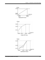
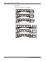
Example 1:
This example shows a standard 0-10V analog input (either from the
keypad potentiometer or an external source). A 0V input = 0hz and 10V
input = maximum output frequency.
Defaults:
20.07=60Hz
30.07=0%
30.08=0
30.09=100%
30.10=0
Maximum Output Frequency
Potentiometer Offset
Bias polarity
Potentiometer slope
Potentiometer direction
Max.
Output (20.07)
Freq.
60Hz
30
0
0Hz
0V
4mA
5-8
0V
5V
12mA
10V
20mA
Hz
60
10V
Potentiometer Scale
Cutler-Hammer MVX9000 User Manual
Chapter 5 – Descriptions of Parameter Settings
Example 2:
This example shows a 10Hz positive offset with full use of the 0-10V
analog input or potentiometer scale. A 0V input = 10Hz and 10V input =
maximum output frequency.
Defaults:
20.07=60Hz
30.07=16.7%
30.08=0
30.09=83.3%
30.10=0
Maximum Output Frequency
(10hz/60hz) x 100=Potentiometer Offset
Bias polarity
Potentiometer Slope
Potentiometer Direction
Calculation of Potentiometer Slope
30.09=(1-30.07) x 100% = 83.3%
Max.
Output (20.07)
Freq.
35
60Hz
10Hz
0
Bias
Adjustment
0Hz 0V
4mA
Cutler-Hammer MVX9000 User Manual
0V
5V
12mA
10V
20mA
Hz
60
10V
Potentiometer Scale
5-9
Chapter 5 – Descriptions of Parameter Settings
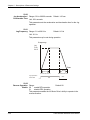
Example 3:
This example shows an analog command range of 0 to 5 Volts, with an
output of 0hz to Maximum Output Frequency.
Defaults:
20.07=60Hz
30.07=0%
30.08=0
30.09=200%
30.10=0
Maximum Output Frequency
Potentiometer Offset
Bias polarity
Potentiometer Slope
Potentiometer direction
Calculation of gain
30.09=(1-
10V
) x 100% = 200%
5V
Max.
Output (20.07)
Freq.
60Hz
Gain adjustment
30
30Hz
0
0V
0Hz 0V
5-10
5V
Hz
60
5V
Potentiometer Scale
Cutler-Hammer MVX9000 User Manual
Chapter 5 – Descriptions of Parameter Settings
Example 4:
In this example a 1-volt negative bias is used. In a noisy environment, it
is advantageous to use negative bias to provide a noise margin (1V in
this example).
Defaults:
20.07=60Hz
30.07=10%
30.08=1
30.09=100%
30.10=0
Maximum Output Frequency
(6/60) x 100% = Potentiometer Offset
Bias polarity
Potentiometer Slope
Potentiometer Direction
Max.
Output (20.07)
Freq.
24
60Hz
54Hz
It's 0Hz
within
this
range.
0Hz
Negative
0V 1V
bias 6Hz
Cutler-Hammer MVX9000 User Manual
10V
0
0V
Hz
54
10V
Potentiometer Scale
5-11
Chapter 5 – Descriptions of Parameter Settings
Example 5:
In this example, the analog input or potentiometer is programmed to
run a motor in both the forward and reverse directions. A motor will be
idle (0hz) when the analog input or potentiometer is at the mid-point of
its scale.
Defaults:
20.07=60Hz
30.07=100%
30.08=1
30.09=200%
30.10=1
Maximum Output Frequency
Potentiometer Offset
Bias polarity
Potentiometer Slope
Potentiometer Direction
Max.
Output (20.07)
Freq.
60Hz
FWD
30Hz
0V
REV.
FWD.
0Hz
5V
10V
30Hz
REV
60Hz
5-12
0
0V
Hz
60
10V
Potentiometer Scale
Cutler-Hammer MVX9000 User Manual
Chapter 5 – Descriptions of Parameter Settings
30.11
Digital Input Terminal
(DI1, DI2)
Range:
01
DI1: FWD / STOP
DI2: REV / STOP
02
Default: 02
Two Wire Operation mode
DI1: RUN / STOP
DI2: REV / FWD
03
3-Wire Operation mode
DI1: RUN
DI2: REV / FWD
DI3: STOP
Setting 01
Setting 02
Setting 03
Cutler-Hammer MVX9000 User Manual
5-13
Chapter 5 – Descriptions of Parameter Settings
30.12
Default: 05
Digital Input Terminal Range:
Not Used
(DI3) 00
01
External Fault (N.O.)
02
External Fault (N.C.)
03
External Reset (N.O.)
04
External Reset (N.C.)
05
Preset Speed Switch 1
06
Preset Speed Switch 2
07
Preset Speed Switch 3
08
Jog
09
2nd Acceleration/Deceleration time selection
10
Control Location - I/O terminals
11
Control Location - keypad
12
Control Location - communication
13
Increase Master Frequency
14
Decrease Master Frequency
15
Forward / Reverse
16
Parameter Lock
17
Acceleration / Deceleration Inhibit
18
Run Enable
19
PAUSE (N.O.)
20
PAUSE (N.C.)
21
PID Disable
22
Run PLC
23
Pause PLC
24
Counter input
25
Counter reset
26
First / Second source of Master Frequency
30.13
Digital Input Terminal Range: See Parameter 30.12
(DI4)
Default: 06
30.14
Digital Input Terminal Range: See Parameter 30.12
(DI5)
Default: 07
30.15 Range: See Parameter 30.12
Digital Input Terminal
(DI6)
5-14
Default: 03
Cutler-Hammer MVX9000 User Manual
Chapter 5 – Descriptions of Parameter Settings
Explanations:
Digital Input Terminal
Settings 01,02
When an External Fault input signal is received, the AC drive output will
turn off, the drive will display “E.F” on digital keypad, and the motor will
coast to a stop. Normal operation will resume after the External Fault is
cleared and the AC drive is reset.
Settings 03,04
The External Reset has the same function as the Reset key on the
Digital keypad. It is used to reset the drive after a fault.
Cutler-Hammer MVX9000 User Manual
5-15
Chapter 5 – Descriptions of Parameter Settings
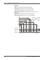
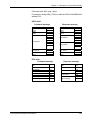
Settings 05, 06, 07
These three inputs select the preset speeds defined by P30.18 to
P30.24.
Switch 1
Switch 2
Switch 3
P 30.18
ON
OFF
OFF
P 30.19
OFF
ON
OFF
P 30.20
ON
ON
OFF
P 30.21
OFF
OFF
ON
P 30.22
ON
OFF
ON
P 30.23
OFF
ON
ON
P 30.24
ON
ON
ON
RO3 RO2 RO1
DI1 DI2 DI3 DI4 DI5 DI6 COM AO+ AI1 +10V AI2 COM DO1 DOC
07:Multi Speed 3
06:Multi Speed 2
05:Multi Speed 1
Freq.
30.18
30.22
Step 1
Step 5
30.23
30.19
Step 6
Step 2
30.21
30.20Step 4
30.24
Step 3
Step 7
Time
Master Freq.
Switch 1
Switch 2
Switch 3
Operation
Command
5-16
ON
ON
ON
ON ON
ON
ON ON
ON ON ON ON
ON
OFF
Cutler-Hammer MVX9000 User Manual
Chapter 5 – Descriptions of Parameter Settings
Setting 08
Jog operation may only be initiated while the motor is stopped. (Refer
to P50.20, P50.21)
Setting 09
Digital input terminals (DI3-DI6) may be used to change from the first to
the second accel/decel time.
Settings 10, 11, 12
Used to select the Operation Command location of the AC drive.
Cutler-Hammer MVX9000 User Manual
5-17
Chapter 5 – Descriptions of Parameter Settings
Settings 13, 14
Setting 13 and 14 enables the digital input terminal to incrementally
increase/decrease the Master Frequency each time an input is
received.
Setting 15
A digital input may be used to select direction.
Setting 16
A digital input terminal may be used to disable users from changing the
parameters.
5-18
Cutler-Hammer MVX9000 User Manual
Chapter 5 – Descriptions of Parameter Settings
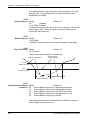
Setting 17
A digital input terminal may be used for acceleration/deceleration
inhibit. When the command is received, acceleration and deceleration
is stopped and the AC drive maintains a constant speed. See diagram
below.
Frequency
Master Frequency
Acceleration
inhibit
Deceleration
inhibit
Acceleration
inhibit
Deceleration
inhibit
Actual operation frequency
Time
Accel/Decel
inhibit
Start command
ON
ON
ON
ON
OFF
ON
Setting 18
Cutler-Hammer MVX9000 User Manual
5-19
Chapter 5 – Descriptions of Parameter Settings
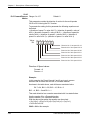
Settings 19, 20
Setting 19 allows an input terminal to generate an “External Pause”.
When the External Pause signal is received, the AC drive will stop all
output and the motor will coast to a stop. When the External Pause
control is removed, the AC drive will start its speed search function,
synchronize with the motor speed, and then accelerate to Master
frequency.
External
Pause
signal
Output
frequency
Output
voltage
Capacitor
discharge
OFF
ON
OFF
Speed search starts with the
reference value
Speed synchronization
detection
50.25
Min. base-block time
Speed search operation
Setting 21
Allows an input terminal to disable PID operation as shown below.
5-20
Cutler-Hammer MVX9000 User Manual
Chapter 5 – Descriptions of Parameter Settings
Settings 22, 23
A setting of 22, allows an input terminal to enable the AC drives internal
PLC program and a setting of 23, allows an input terminal to pause the
PLC program.
Settings 24
A digital input terminal may be used to increase the AC drive’s internal
counter. When an input is received, the counter is increased by 1. The
counter input may be connected to an external Pulse Signal Generator
to count a process or unit of material. See the diagram below.
Cutler-Hammer MVX9000 User Manual
5-21
Chapter 5 – Descriptions of Parameter Settings
Settings 25
A digital input terminal may be used to reset the counter as shown
below.
Settings 26
A digital input terminal may be used to select the first or second Source
of Master Frequency as shown below.
RO3 RO2 RO1
DI1 DI2 DI3 DI4 DI5 DI6 COM AO+ AI1 +10V AI2 COM DO1 DOC
26:First/second source of frequency command
30.16
Final Count Value Range: 00 to 9999
Default: 00
This parameter defines the final count value for the MVX9000 internal
counter. The counter is incremented by a low-to-high transition on a
Digital Input Terminal: DI3 to DI6.
A selected Digital/Relay Output Terminal may be programmed to
activate upon completion of the final count.
30.17
Intermediate Count Value Range: 00 to 9999
Default: 00
This parameter sets the intermediate count value for the MVX9000
internal counter. The counter is incremented by a low-to-high transition
on a Digital Input Terminal: DI3 to DI6. The count will start at c01.
A selected Digital/Relay Output Terminal may be programmed to
activate upon completion of the intermediate count.
30.18
Preset Speed 1 Range: 0.0 to 400.0 Hz
Unit: 0.1 Hz
30.19
Preset Speed 2 Range: 0.0 to 400.0 Hz
Default: 0.0 Hz
Default: 0.0 Hz
Unit: 0.1 Hz
5-22
Cutler-Hammer MVX9000 User Manual
Chapter 5 – Descriptions of Parameter Settings
30.20
Preset Speed 3 Range: 0.0 to 400.0 Hz
Default: 0.0 Hz
Unit: 0.1 Hz
30.21
Preset Speed 4 Range: 0.0 to 400.0 Hz
Default: 0.0 Hz
Unit: 0.1 Hz
30.22
Preset Speed 5 Range: 0.0 to 400.0 Hz
Default: 0.0 Hz
Unit: 0.1 Hz
30.23
Preset Speed 6 Range: 0.0 to 400.0 Hz
Default: 0.0 Hz
Unit: 0.1 Hz
30.24
Preset Speed 7 Range: 0.0 to 400.0 Hz
Default: 0.0 Hz
Unit: 0.1 Hz
These parameters may be set during operation.
The Digital Input Terminals (refer to 30.11 to 30.15) are used to select
one of the MVX9000 Preset Speeds. The speeds (frequencies) are
determined by 30.18 to 30.24.
Preset Speeds 30.18 to 30.24 in conjunction with 50.46 to 50.52
provide the process logic control (PLC) function.
30.25
Display Frequency (Hz) Range:
or Percent (%) 00 Frequency (hz)
01 Percent (%)
Default: 00
This parameter allows the display to reference Frequency or
Percentage.
30.26
Digital Extension Input Range: See Parameter 30.12
DI7
Default: 00
30.27
Digital Extension Input Range: See Parameter 30.12
DI8
Default: 00
Available settings are the same as 30.12 to 30.15
These parameters select the function of the optional extension I/O.
These parameters are not visible on the MVX9000 until the extension
I/O is installed.
Cutler-Hammer MVX9000 User Manual
5-23
Chapter 5 – Descriptions of Parameter Settings
Group 40 — Outputs
40.01
Default: 00
Analog Output Signal Range:
00 Output Frequency (0 to Maximum Output Frequency)
01 Output Current (0 to 250% of the rated AC drive current)
02 PID Feedback Signal (0 to maximum feedback)
03 Output Power (0 to 100% of the rated AC drive power)
This parameter selects the reference value for the 0-10V analog output
(AO+ to COM).
40.02
Analog Output Gain Range: 0 to 200%
Default: 100
Unit: 1%
This parameter may be set during operation.
The parameter sets the voltage range for analog output terminals AO+
to COM.
The analog output voltage is directly proportional to the selection made
in 40.01.
If setting 00 is chosen, the analog output voltage on AO+ to COM is
directly proportional to the output frequency of the AC drive. With 40.02
set at 100%, the Maximum Output Frequency of the AC drive
corresponds to +10VDC on AO.
If setting 01 is chosen, the analog output voltage is directly proportional
to the output current of the AC drive. With 40.02 set to 100%, +10 VDC
corresponds to 250% of AC drive rated current.
Note: Any type of voltmeter may be used. If the meter reads full scale
at a voltage less than 10 volts, then 40.02 should be set by the
following formula:
40.02 = ((meters full scale voltage)/10)×100%
For Example: When using the meter with full scale of 5 volts, adjust
40.02 to 50%
5-24
Cutler-Hammer MVX9000 User Manual
Chapter 5 – Descriptions of Parameter Settings
40.03
Digital Output Terminal Range: 00 to 20
D01
Default: 02
40.04
Default: 03
Relay Output Terminal Range: 00 to 20
Not Used
RO1, RO2, RO3 00
01
Ready
02
Inverter Running
03
Inverter Fault
04
Warning (See warning codes in Chapter 7)
05
At speed
06
Zero Speed
07
Above desired frequency (40.05)
08
Below desired frequency (40.05)
09
PID supervision
10
Over voltage supervision
11
Over heat supervision
12
Over current stall supervision
13
Over voltage stall supervision
14
Low voltage indication
15
PLC program running
16
PLC program step complete
17
PLC program completion
18
PLC program pause
19
Terminal count value attained
20
Preliminary count value attained
21
Reverse direction notification
22
Under current detection
Cutler-Hammer MVX9000 User Manual
5-25
Chapter 5 – Descriptions of Parameter Settings
Function Explanations:
00
Not Used: all unused output terminals of the AC drive should be set to 00.
01
Ready: The output terminal will be active when the drive has no faults and is ready to run.
02
Inverter Running: The output terminal will be active when the drive is generating an output
from the T1, T2, T3 terminals.
03
Inverter Fault: The output terminal will be activated when faults occur (oc, ov, oH, oL, oL1, EF,
cF3, HPF, ocA, ocd, ocn, GF).
04
Warning: The output terminal will be active when there is a fault with communication or PID
feedback.
05
At Speed: The output terminal will be active when the drive output frequency reaches the
value set by your command source.
06
Zero Speed: The output terminal will be active when the drives U, V, W terminals are
generating no output.
07
Above Desired Frequency: The output terminal will be active when the output frequency is
above the desired frequency (40.05).
08
Below Desired Frequency: The output terminal will be active when the output frequency is
below the desired frequency (40.05).
09
PID supervision
10
Over Voltage Warning: The output terminal will be active when output voltage of the drive
exceeds 90% of the maximum voltage limit.
11
Over Heat Warning: The output terminal will be active when temperature of the drive exceeds
90% of the maximum heat limit.
12
Over Current Stall Warning: The output terminal is active when the Over current stall function
is enabled.
13
Over Voltage Stall Warning: The output terminal will be active when the over voltage stall
function is enabled.
14
Low Voltage: The output will be active when the input voltage drops below the minimum
voltage limit.
15
PLC Program running: The output terminal will be active when the PLC function is running.
16
PLC Program Step complete: The output terminal will be active when each PLC step is
completed.
17
PLC Program Completed: The output terminal will be active when the PLC function has
completed and stopped.
18
PLC Program Pause: The output terminal will be active when the PLC function has been
paused.
Final count value attained: The output terminal will be active when the count reaches the
19
setting in 30.16.
Intermediate count value attained: The output terminal will be active when the count reaches
20
the setting in 30.17.
21
Reverse direction notification: The output terminal will be active when the drive is in reverse.
Under current detection: The output terminal will be active when the output current is under Pr.
22
70.11 and the time has exceeded Pr. 70.13.
5-26
Cutler-Hammer MVX9000 User Manual
Chapter 5 – Descriptions of Parameter Settings
40.05
Desired Frequency Range: 0.0 to 400.0 Hz
Attained
Unit: 0.1Hz
Default: 0.0
If a Digital/Relay output terminal is set to function as Desired
Frequency, then the output will be activated when the programmed
frequency is attained.
40.06
Relay Extension Output Range: See Parameter 40.03
RO4, RO5, RO6
Default: 00
40.07
Relay Extension Output Range: See Parameter 40.03
RO7, RO8, RO9
Default: 00
Available settings are the same as 40.03 to 40.04.
These parameters select the function of the optional extension I/O.
These parameters are not visible on the MVX9000 until the extension
I/O is installed.
Cutler-Hammer MVX9000 User Manual
5-27
Chapter 5 – Descriptions of Parameter Settings
Group 50 — AC Drive Control
50.01
Default: 01
Source of Master Range:
Frequency 00 Master Frequency determined by digital keypad on the drive.
01 Master Frequency determined by keypad potentiometer.
02 Master Frequency determined by 0-10V on terminal AI1
03 Master frequency determined by 4-20mA on terminal AI2
04 Master frequency determined by RS485
50.02
Default: 00
Source of Operation Range:
Command 00 Operating commands determined by the Digital Keypad.
01 Operating commands determined by the External Control
Terminals. Keypad STOP key is enabled.
02 Operating commands determined by the External Control
Terminals. Keypad STOP key is not enabled.
03 Operating commands determined by the RS-485
communication interface. Keypad STOP key is enabled.
04 Operating commands determined by the RS-485
communication interface. Keypad STOP key is not enabled.
50.03
Stop Method Range:
00 Ramp to stop
01 Coast to stop
Default: 00
This parameter determines how the motor is stopped when the AC
drive receives a valid stop command.
Ramp: The AC drive decelerates the motor to the Minimum Output
Frequency based on the time set in Pr. 50.12.
Coast: The AC drive stops the output instantly upon command, and the
motor free spins until it comes to a complete stop.
Hz
Hz
Freq.
Freq.
Motor
Speed
Motor
Speed
Operation
command
Stops according
to deceleration
time
ON
OFF
Ramp
5-28
Time
Time
Free running
to stop
ON
OFF
Coast
Cutler-Hammer MVX9000 User Manual
Chapter 5 – Descriptions of Parameter Settings
50.04
Maximum Output Range: 50.0 to 400.0 Hz
Frequency
Unit: 0.1Hz
Default: 60
This parameter determines the AC drive’s Maximum Output
Frequency. All the AC drive accelerations and decelerations are scaled
to correspond to this maximum output frequency.
50.05
Motor Nameplate Range: 10.0 to 400.0Hz
Frequency
Unit: 0.1Hz
Default: 60
This value should be set according to the rated frequency of the motor
as indicated on the motor nameplate. Motor Nameplate Frequency
determines the volts/hertz ratio.
For example: if the drive is rated for 460 VAC output and the Motor
Nameplate Frequency is set to 60Hz, the drive will maintain a constant
ratio of 7.66 v/Hz. The setting value must equal to or greater than
the Mid-Point Frequency (50.07).
50.06
Motor Nameplate Voltage Range: 230V series 0.1 to 255.0V
Default: 230.0
Range: 460V series 0.1 to 510.0V
Default: 460.0
This parameter determines the motor nameplate voltage of the AC
drive. The motor nameplate voltage setting must be smaller than or
equal to the rated voltage of the motor as indicated on the motor
nameplate. The setting value must equal to or greater than the
Mid-Point Voltage (50.08).
50.07
Mid-Point Output Range: 0.1 to 400.0Hz
Frequency
Unit: 0.1Hz
Default: 1.5
The parameter sets the Mid-Point Frequency of V/F curve. With this
setting, the V/F ratio between Minimum Frequency and Mid-Point
frequency can be determined. This parameter must be equal to or
greater than Minimum Output Frequency (50.09) and equal to or
less than Motor Nameplate Frequency (50.05).
During Sensorless Vector this parameter is disabled.
Cutler-Hammer MVX9000 User Manual
5-29
Chapter 5 – Descriptions of Parameter Settings
50.08
Mid-Point Output Voltage Range: 230V series 0.1 to 255V Default: 10.0
Range: 460V series 0.1 to 510V Default: 20.0
The parameter sets the Mid-Point Voltage of any V/F curve. With this
setting, the V/F ratio between Minimum Frequency and Mid-Point
Frequency can be determined. This parameter must be equal to or
greater than Minimum Output Voltage (50.10) and equal to or less
than Motor Nameplate Voltage (50.06).
During Sensorless Vector this parameter is disabled.
50.09
Minimum Output Range: 0.1 to 20.0Hz
Frequency
Unit: 0.1Hz
Default: 1.5
This parameter sets the Minimum Output Frequency of the AC drive
V/F curve. This parameter must be equal to or less than the Mid-Point
Output Frequency (50.07).
50.10
Minimum Output Voltage Range: 230V series 0.1 to 50V
Default: 10.0
Range: 460V series 0.1 to 100V Default: 20.0
This parameter sets the Minimum Output Voltage of the AC drive V/F
curve. This parameter must be equal to or less than Mid-Point Output
Voltage (50.08).
During Sensorless Vector this parameter is disabled.
Below are three examples of how a V/F curve may change due to the
setting of parameters 50.04 to 50.10.
50.11
Range:
Default: 00
Sensorless Vector 00: Disabled
Enable 01: Enabled
This parameter enables the Sensorless Vector function. When the
drive is set for Sensorless Vector the starting torque will be 150% at
1hz. Also the Mid-Point Output Frequency, Mid-Point Output Voltage,
and Minimum Output Voltage are disabled. For the best results, please
conduct the following.
1. Set the correct motor nameplate voltage and Base Frequency
2. Conduct an Auto tune. (See parameter 60.03)
3. Set the Minimum output Frequency (50.09) to 0.1Hz
5-30
Cutler-Hammer MVX9000 User Manual
Chapter 5 – Descriptions of Parameter Settings
Cutler-Hammer MVX9000 User Manual
5-31
Chapter 5 – Descriptions of Parameter Settings
50.12
Acceleration Time 1 Range: 0.01 to 600.00 seconds
Default: 10s
Unit: 0.01 seconds
50.13
Deceleration Time 1 Range: 0.01 to 600.00 seconds
Default: 10s
Unit: 0.01 seconds
50.14
Acceleration Time 2 Range: 0.01 to 600.00 seconds
Default: 10s
Unit: 0.01 seconds
50.15
Deceleration Time 2 Range: 0.01 to 600.00 seconds
Default: 10s
Unit: 0.01 seconds
These parameters may be set during operation.
50.12: This parameter sets the time required for the AC drive to ramp
from 0 Hz to its Maximum Output Frequency (50.04). The rate is linear
unless S-Curve is “Enabled.”
50.13: This parameter sets the time required for the AC drive to
decelerate from the Maximum Output Frequency (50.04) down to 0 Hz.
The rate is linear unless S-Curve is “Enabled.”
The second acceleration and deceleration times (50.14 and 50.15) are
identical to the standard acceleration and deceleration times (50.12 and
50.13). The second acceleration and deceleration times are used only
when a Digital input terminal is programmed to select between times 1
and 2 (Refer to 30.12 to 30.15) or when a frequency other than 0 is set in
parameters 50.16 and 50.17.
In the diagram shown below, the acceleration and deceleration times of
the AC drive are between 0 Hz and Maximum Output Frequency (50.04).
If the Maximum Output Frequency is 60 Hz, Minimum Output Frequency
(50.09) is 1.0Hz, and acceleration and deceleration times are set to 10
seconds. The actual time for the AC drive to accelerate from start-up to
60 Hz is 9.83 seconds and the deceleration time is also 9.83 seconds.
Remember the drive always starts timing from 0Hz.
Frequency
Max.
Output
Freq.
50.04
Time
50.12 or 50.14
Acceleration Time
5-32
50.13 or 50.15
Deceleration Time
Cutler-Hammer MVX9000 User Manual
Chapter 5 – Descriptions of Parameter Settings
50.16
Transition Point for Range:
Disabled
Acceleration Time 1 to 2 0.0
0.1 to 400hz Enabled
Default: 0.0
50.17
Transition Point for Range:
Disabled
Deceleration Time 1 to 2 0.0
0.1 to 400Hz Enabled
Default: 0.0
50.18
Acceleration S-Curve Range:
00
Disabled
01 to 07 Enabled
Default: 00
50.19
Deceleration S-Curve Range: See Parameter 50.18
Default: 00
The above two parameters are used to smooth out the transition
between the acceleration/deceleration and steady state speed. The
S-Curve is enabled with settings of 1 to 7, with the highest number
generating the smoothest transition.
Freq.
S curve Enabled
Time
S-curve
characteristics
S-curve
characteristics
S curve Disabled
Normal Acceleration Time
1 or 2
Cutler-Hammer MVX9000 User Manual
Normal Deceleration Time
1 or 2
5-33
Chapter 5 – Descriptions of Parameter Settings
50.20
Jog Acceleration / Range: 0.01 to 600.00 seconds
Deceleration Time
Unit: 0.01 seconds
Default: 1.00 sec
This parameter sets the acceleration and deceleration time for the Jog
operation.
50.21
Jog Frequency Range: 0.1 to 400.0 Hz
Default: 6.0 Hz
Unit: 0.1 Hz
This parameter may be set during operation.
Frequency
Jog
Freq.
50.21
Time
50.20
50.20
Acceleration time
Jog Operation
Command
ON
50.22
Reverse Operation Range:
enable REV operation
Enable 00
01
disable REV operation
Deceleration time
OFF
Default: 00
This parameter enables the AC Motor Drive’s ability to operate in the
reverse direction.
5-34
Cutler-Hammer MVX9000 User Manual
Chapter 5 – Descriptions of Parameter Settings
50.23
Default: 00
Momentary Power Loss Range:
Operation stops after momentary power loss
and Flying Start 00
Operation continues after momentary power loss and flying
Operation 01
start search starts with the Master Frequency reference value
02
Operation continues after momentary power loss and flying
start search starts with the minimum frequency
50.24
Maximum Allowable Range: 0.3 to 5.0 seconds
Power Loss Time (Ride
Unit: 0.1seconds
Through)
Default: 2.0 sec
During a power loss, if the power loss time is less than the time defined
by this parameter, the AC drive will resume operation. If the Maximum
Allowable Power Loss Time is exceeded, the AC drive output is then
turned off.
If the power loss occurs while the AC drive is under heavy load, it is
possible that all available ride through power will be dissipated in the
motor and the AC drive will shut down quickly (less than 1 second).
50.25
Pause Time after Range: 0.3 to 10 seconds
Momentary Power loss
Unit: 0.1 seconds
(delay before restart)
Default: 0.5 sec
When a momentary power loss is detected, the AC drive waits for a
specified time interval determined by 50.25 before resuming operation.
This time interval should be set to a value where the residual output
voltage due to regeneration is nearly zero, before the drive resumes
operation.
This parameter also determines the wait time after performing an
external PAUSE and Fault Reset function.
Cutler-Hammer MVX9000 User Manual
5-35
Chapter 5 – Descriptions of Parameter Settings
50.26
Maximum Speed Search Range: 30 to 200%
Current Level
Unit: 1%
Default: 150%
Following a momentary power failure, the AC drive will start its speed
search operation, only if the output current is greater than the value
determined by 50.26. When the output current is less than that of
50.26, the AC drive output frequency is at a “speed synchronization
point”. The drive will begin to accelerate or decelerate the motor back to
the operating frequency at which it was running prior to the power
failure.
Max. Allowable Power Loss Time
Input
Power
Output
Power
Output
Voltage
50.24
Allowable Max. power loss time
50.24
speed synchronization
detection
50.23=01
Speed search starts with
the Master Frequency
50.23=02
Speed search starts with
minimum output frequency
Baseblock
Time
Baseblock
Time
50.25
50.24
speed search
50.27
Upper Limit of Output Range: 0.1Hz to 400.0Hz
Frequency
Unit: 0.1Hz
Default: 400.0 Hz
This parameter must be equal to or greater than the Lower Limit of
Output Frequency 50.28.
50.28
Lower Limit of Output Range: 0.0Hz to 400.0Hz
Frequency
Unit: 0.1Hz
Default: 0.0 Hz
The Upper and Lower Limit parameters are to prevent operation at
frequencies where machine damage may occur.
If the Upper Limit of Output Frequency is set at 50Hz and the Maximum
Output Frequency is set at 60Hz, the actual Maximum Output
Frequency will be limited to 50Hz.
If the Lower limit of Output Frequency is set at 10Hz, and the Minimum
Output Frequency is set at 1.0Hz, then any Command Frequency
between 1-10Hz will generate a 10Hz output from the drive.
This parameter must be equal to or less than the Upper Limit of Output
Frequency 50.27.
5-36
Cutler-Hammer MVX9000 User Manual
Chapter 5 – Descriptions of Parameter Settings
50.29
Skip Frequency 1 Range: 0.0 to 400.0 Hz
Default: 0.0
Unit: 0.1 Hz
50.30
Skip Frequency 2 Range: 0.0 to 400.0 Hz
Default: 0.0
Unit: 0.1 Hz
50.31
Skip Frequency 3 Range: 0.0 to 400.0 Hz
Default: 0.0
Unit: 0.1 Hz
These three parameters determine the three Skip Frequencies that, in
conjunction with 50.32, Skip Frequency Bandwidth, will cause the AC
motor drive to skip operation at each frequency band.
50.32
Skip Frequency Range: 0.0 to 20.0 Hz
Bandwidth
Unit: 0.1 Hz
Default: 0.0
This parameter determines the frequency band for a given Skip
Frequency. Half of the Skip Frequency Band is above the Skip
Frequency and the other half is below. Programming this parameter to
0.0 disables all skip frequencies.
output
freq.
50.29
50.30
Adjustable
range
50.31
0
Speed command
frequency
Decelerating
Accelerating
50.33
Auto Restart After Fault Range: 00 to 10
50.32
Freq. to
be skipped
Default: 00
Number of times to restart
After a fault occurs (allowable faults: over-current OC, over-voltage
OV), the AC drive can be reset/restarted automatically up to 10 times.
Setting this parameter to 0 will disable the reset/restart operation after
any fault has occurred. When enabled, the AC drive will restart using
the speed search function, which starts at the Master Frequency
reference value. To set the fault recovery time after a fault, please see
50.25, Pause Time.
Cutler-Hammer MVX9000 User Manual
5-37
Chapter 5 – Descriptions of Parameter Settings
50.34
Default: 00
PID Set-Point Location Range:
00
Disable
01
Keypad (based on setting of 20.03)
02
AI1 (external 0-10V)
03
AI2 (external 4-20mA)
04
Parameter 50.43 (non-variable set point)
50.35
Default: 00
Feedback Signal Range:
Positive Feedback AI1 (0-10V)
Selection 00
01
Negative Feedback AI1 (0-10V)
02
Positive Feedback AI2 (4-20mA)
03
Negative Feedback AI2 (4-20mA)
This parameter selects the PID analog feedback type.
50.36
P (Gain) adjustment Range: 0.0 to 10.0
50.37
I (Integration) adjustment Range: 0.0 to 100.0 seconds
Default: 1.0
Default: 1.0sec
Units: 0.1seconds
When parameter is set to 0.0 the function is disabled.
50.38
D (Derivative) adjustment Range: 0.0 to 1.0 sec
Default: 0.0sec
Units: 0.1 seconds
When parameter is set to 0.0 the function is disabled.
50.39
Upper Limit of Integral Range: 00 to 100%
Control
Default: 100%
50.40
PID Output Delay Filter Range: 0.0 to 2.5 seconds
Time
Units: 0.1seconds
Default: 0.0sec
5-38
Cutler-Hammer MVX9000 User Manual
Chapter 5 – Descriptions of Parameter Settings
50.41
4 - 20mA Input Loss Range: 0.1 to 3600 seconds
Disabled
Detection Time 00
Default: 60sec
Units: 0.1second
If the 4-20mA input falls below 4mA, the drive will consider this a loss of
input speed command. Upon loss of 4-20mA, the AC drive will begin to
record time. If the time set in 50.41 is reached, the AC drive will follow
the operation selection in 50.42.
50.42
Default: 00
4 – 20mA Input Loss Range:
Warn and Stop operation
Operation 00
01
Warn and continue to run at last known speed command
This parameter selects the operation of the AC drive after a loss of
4-20mA input is detected and the time set in 50.41 is reached. This
parameter is disabled if 30.04 is set to 0.0mA.
50.43
PID Set-Point Range:
0.1 to 400.0hz
00hz Disabled
Default: 00hz
Units: 0.1hz
This parameter sets the frequency target value for the PID function.
50.44
Default: 00
PLC Operation Mode Range:
00
Disable PLC operation
01
Execute one program cycle
02
Continuously execute program cycles
03
Execute one program cycle step by step
04
Continuously execute program cycles step by step
This parameter selects the function of the PLC operation. The PLC
program may be used in lieu of any External Controls, Relays or
Switches. The AC drive will change speeds and directions according to
the user’s programming.
Cutler-Hammer MVX9000 User Manual
5-39
Chapter 5 – Descriptions of Parameter Settings
Example 1
50.44 = 1: Execute one cycle of the PLC program.
30.18 to 30.24: Frequency of 1st to 7th step speeds.
30.12 to 30.15: Digital Input Terminals (set one to 22).
40.03 to 40.04: Digital/Relay Output Terminals (may be set to 15
through 18).
50.45: Direction of operation for 1st to 7th step speed.
50.46 to 50.52: Operation time of 1st to 7th step speeds.
Frequency
30.21
60Hz
30.22
50Hz
30.20
40Hz
30.15=22
40.03=15
40.04=16
50.44=01
50.45=00
50.46=10
50.47=12
50.48=15
50.49=15
50.50=08
50.51=17
50.52=17
30.23
30Hz
30.19
20Hz
15Hz
10Hz
30.18=10 Hz
30.19=20 Hz
30.20=40 Hz
30.21=60 Hz
30.22=50 Hz
30.23=30 Hz
30.24=15 Hz
30.24
30.18
0Hz
50.46
50.47
50.48
50.49
50.50
50.51
50.52
Program operation
command
Program operation
output indication
Program step
complete
Program operation
completed
5-40
Cutler-Hammer MVX9000 User Manual
Chapter 5 – Descriptions of Parameter Settings
Example 2 (50.44 = 01) Execute one cycle through the PLC
program:
In this example, the PLC program runs continuously. It should be noted
that the times of reverse motion may be shorter than expected, due to
the acceleration/deceleration time.
Frequency
30.21
60Hz
30.23
50Hz
30.20
40Hz
30.18=10 Hz
30.19=20 Hz
30.20=40 Hz
30.21=60 Hz
30.22=50 Hz
30.23=30 Hz
30.24=15 Hz
30.15=22
40.03=15
40.04=16
50.44=01
50.45=34
50.46=10
50.47=12
50.48=15
50.49=15
50.50=08
50.51=17
50.52=17
FWD
15Hz
10Hz
50.52
30.18
50.47
30.24
Time
0Hz
REV
20Hz
50.49
50.46
30.19
30Hz
50.50
50.51
50.48
30.23
Application Note:
Changing the value of Jog parameters 50.20 and 50.21 will interrupt
PLC program execution. PLC program execution will not be interrupted
when other parameter values are changed.
Cutler-Hammer MVX9000 User Manual
5-41
Chapter 5 – Descriptions of Parameter Settings
50.45
PLC Forward/Reverse Range: 0 to 127
Motion
Default: 0
This parameter controls the direction of motion for the multi-speeds
30.18 to 30.24 during the PLC function.
To generate the setting for this parameter the following equation must
be solved.
= (direction of speed 7 x value of bit 7) + (direction of speed 6 x value of
bit 6) + (direction of speed 5 x value of bit 5) + (direction of speed 4 x
value of bit 4) + (direction of speed 3 x value of bit 3) + (direction of
speed 2 x value of bit 2) + (direction of speed 1 x value of bit 1)
Value
Bit
64 32 16 8 4
2
1
7 6 5 4 3 2 1
Direction bit of 1st speed 30. 18
Direction bit of 2nd speed 30.19
Direction bit of 3rd speed 30.20
Direction bit of 4th speed 30.21
Direction bit of 5th speed 30.22
Direction bit of 6th speed 30.23
Direction bit of 7th speed 30.24
Direction of Speed values:
Forward = 0
Reverse = 1
Example:
In this example, the Preset Speeds 6 and 2 are to go in reverse
direction and all others are to move in a forward direction.
As shown in the table above, each bit has an associated value.
Bit 7 = 64, Bit 6 = 32, Bit 5 = 16, Bit 4 = 8
Bit 3 = 4, Bit 2 = 2 and Bit 1 = 1
Then each direction has a number associated with it as stated below.
Use the number 0 for a Forward direction.
Use the number 1 for a Reverse direction.
With the above information the equation can be solved.
= (0 x 64)+(1 x 32)+(0 x 16)+(0 x 8)+(0 x 4)+(1 x 2)+(0 x 1)
= 0+32+0+0+0+2+0
50.45 = 34 for this example
5-42
Cutler-Hammer MVX9000 User Manual
Chapter 5 – Descriptions of Parameter Settings
50.46
Time Duration of 1st Range: 0 to 9999
Preset Speed
Unit: 1 sec
Default: 0
50.47
Time Duration of 2nd Range: 0 to 9999
Preset Speed
Unit: 1 sec
Default: 0
50.48
Time Duration of 3rd Range: 0 to 9999
Preset Speed
Unit: 1 sec
Default: 0
50.49
Time Duration of 4th Range: 0 to 9999
Preset Speed
Unit: 1 sec
Default: 0
50.50
Time Duration of 5th Range: 0 to 9999
Preset Speed
Unit: 1 sec
Default: 0
50.51
Time Duration of 6th Range: 0 to 9999
Preset Speed
Unit: 1 sec
Default: 0
50.52
Time Duration of 7th Range: 0 to 9999
Preset Speed
Unit: 1 sec
Default: 0
50.46 to 50.51 set the operation time of each Preset Speed during the
PLC operation mode.
The maximum value of these parameters is 9999 seconds and is
displayed as 9999.
Note: If a time is set to “0” (0 Sec), the corresponding speed will be
skipped. This is used to reduce the number of program steps.
50.53
Default: 00
Auto Acceleration Range:
Linear acceleration and deceleration
Deceleration 00
01
Auto acceleration and linear deceleration
02
Linear acceleration and auto deceleration
03
Auto acceleration and deceleration
04
Auto acceleration and deceleration, but limited by
50.12 to 50.15
Linear acceleration and deceleration times are based on 50.12 to 50.15
If this parameter is set to 03, the AC drive will accelerate and
decelerate in the fastest and smoothest means possible by
automatically adjusting the time of acceleration and deceleration.
Cutler-Hammer MVX9000 User Manual
5-43
Chapter 5 – Descriptions of Parameter Settings
If the application has a high duty cycle of starts and stops or the load
changes often, it is recommended to use linear Acceleration and
Deceleration for stability.
50.54
Default: 0.0
Sleep Frequency Range:
0.0
Disabled
0.1 to 400hz Enabled
The Master Frequency point where the AC drive begins to “Sleep” and
stop its output. Note: The sleep frequency must be smaller than or
equal to the wake frequency.
50.55
Default: 0.0
Wake Frequency Range:
0.0 to 400hz
The Master Frequency point where the drive begins to output again.
50.56
Default: 1.0
Sleep Time Delay Range:
0.0 to 600 sec.
The time delay before going into a sleep mode.
Frequency Command
Actual running
output frequency
50.55
Wake Frequency
50.54
Sleep Frequency
50.56
0Hz
Sleep Time Delay
50.57
Default: 00
Second Source of Master Range:
Second Master Frequency by digital keypad up/down
Frequency 00
01
Second Master Frequency by keypad potentiometer
02
Second Master Frequency by 0 to +10V input on AI1
03
Second Master Frequency by 4 to 20mA input on AI2
04
Second Master Frequency by RS-485
This parameter determines the Second Source of Master Frequency
when a digital input switch is used.
5-44
Cutler-Hammer MVX9000 User Manual
Chapter 5 – Descriptions of Parameter Settings
Group 60 — Motor Control
60.01
Motor Rated Current Default: xx.x A
Enter the motor’s nameplate rated amps.
The value must be between 30 to 120% of the drive’s rated output
current. This parameter sets the drive’s output current limit.
This parameter may be set during operation.
60.02
Motor No-Load Current Default: xx.x A
Enter the motor’s no load current in Amps. If the motor no load amps
are not known, leave this parameter at factory default.
The value must be between 0 to 99% of the drive’s rated output current
and also less than parameter 60.01.
60.02 has a great effect on how accurate the slip compensation
function works. An incorrect setting will cause poor slip compensation.
This parameter may be set during operation.
60.03
Default: 00
Motor Auto Tuning Range:
00
Disabled
01
DC test only
02
DC test and no load current test
To conduct the auto tuning feature, select 01 or 02 and then press
“Start”. If the motor is loaded, it is recommended to select 01.
60.04
Motor’s Stator Range: 00 to 65535 m Ohms
Resistance
Units: milli-ohms
Default: 00
This parameter determines the motor’s line-to-line resistance. The
value may be entered manually or via the Auto Tune feature 60.03.
This value should be entered when using Sensorless Vector control.
Cutler-Hammer MVX9000 User Manual
5-45
Chapter 5 – Descriptions of Parameter Settings
60.05
DC Braking Current Level Range: 0 to 100%
Default: 00
Unit: 1%
This parameter determines the amount of DC Braking Current applied
to the motor during start-up and stopping. When setting DC Braking
current, please note that 100% is equal to the rated output current of
the drive. It is recommended to start with a low DC Braking Current
Level and then increase until proper holding torque has been attained.
60.06
DC Braking Time upon a Range: 0.0 to 5.0 seconds
Start
Unit: 0.1seconds
Default: 0.0
This parameter determines the duration of time that the DC Braking
Current will be applied to the motor upon a start command of the AC
drive. DC Braking will be applied for the time set in this parameter until
the Minimum Frequency is reached during acceleration.
60.07
DC Braking Time upon a Range: 0.0 to 25.0 seconds
Stop
Unit: 0.1seconds
Default: 0.0
This parameter determines the duration of time that the DC braking
current will be applied to the motor upon a stop command of the AC
drive.
Parameter 50.03 must be set to RAMP to stop, for DC braking to be
enabled.
5-46
Cutler-Hammer MVX9000 User Manual
Chapter 5 – Descriptions of Parameter Settings
60.08
Frequency Point for DC Range: 0.0 to 60.0Hz
Braking
Unit: 0.1Hz
Default: 0.0
This parameter determines the Frequency Point for DC Braking to
begin upon a stop command.
Master
Frequency
Min. output
Freq.
Operation
command
60.08
60.06
Start-point
for DC
braking
time(s)
60.07
OFF
ON
DC Braking Current %
60.05
Note: DC Braking during Start-up is used for loads that may move
before the AC drive starts, such as fans and pumps. These loads
may also be moving in the wrong direction. Under such
circumstances, DC Braking can be executed to hold the load in
position before applying a forward motion.
DC Braking during stopping is used to decrease stopping time and also
to hold a stopped load in position. For high inertia loads, a dynamic
braking resistor may be needed for quick decelerations.
60.09
Torque Compensation Range: 00 to 10%
Default: 00%
Units: %
This parameter selects the % of increased voltage upon acceleration of
the AC drive. This is helpful during start-up to obtain a higher initial
starting torque. Increased voltage to the motor also increases current
and heat. Always start with a low Torque Compensation value and
slowly increase until sufficient starting torque is achieved.
This parameter may be set during operation.
Cutler-Hammer MVX9000 User Manual
5-47
Chapter 5 – Descriptions of Parameter Settings
60.10
Slip Compensation Range: 0.00 to 10.00
Default: 0.00 for V/F
Default: 1.00 for vector
An increasing load on an asynchronous motor will cause an increase in
motor slip. This Slip Compensation parameter may be used to
compensate for the nominal slip within a range of 0 to 10%.
When the output current of the AC drive is greater than the motor
no-load current (60.02) the AC drive will adjust its output frequency to
help keep rotor speed constant. The maximum increase in output
frequency is determined by the setting of this parameter. A setting of
5% will increase output frequency from 60hz to 63hz percentage.
This parameter may be set during operation.
60.11
PWM Carrier Frequency Range:
01
fc= 1KHz
02
fc= 2KHz
03
fc= 3KHz
:
15
Default: 09
:
:
fc= 15KHz
The parameter selects the carrier frequency for the PWM (Pulse-Width
Modulated) function.
Carrier Frequency
Acoustic Noise
Electromagnetic
Noise, Leakage
Current
Heat Dissipation
1KHz
Significant
Minimal
Minimal
15KHz
Minimal
Significant
Significant
From the above table, we see that the carrier frequency for the PWM
function has a significant influence on the electromagnetic noise, heat
dissipation of the AC drive, and the acoustic noise of the motor.
5-48
Cutler-Hammer MVX9000 User Manual
Chapter 5 – Descriptions of Parameter Settings
Group 70 — Protective Functions
70.01
Default: 01
Over-voltage Stall Range:
Disable Over-Voltage Stall Prevention
Prevention 00
01
Enable Over-Voltage Stall Prevention
During deceleration, the AC drive’s DC bus voltage may exceed its
maximum allowable value due to motor regeneration. When this
function is enabled, the AC drive will stop decelerating, and maintain a
constant output frequency. The drive will resume deceleration when
the voltage drops below the factory-preset value.
Note: With moderate inertia loads, over-voltage during deceleration
will not occur. For application with high inertia loads, the AC
drive will automatically extend the deceleration time. If
deceleration time is critical for the application, then a dynamic
braking resistor should be used.
70.02
Over-Current Stall Range:
Prevention during 00: disable
Acceleration 20 to 200%: enable
Default: 150%
Unit: 1%
A setting of 100% is equal to the Rated Output Current of the drive.
Under certain conditions, the AC drive output current may increase
abruptly, and exceed the value specified by 70.02. This is commonly
caused by a rapid acceleration or excessive loading on the motor.
When 70.02 is enabled, the AC drive will stop accelerating and
maintain a constant output frequency. The AC drive will only resume
acceleration when the current drops below the value set in 70.02.
Cutler-Hammer MVX9000 User Manual
5-49
Chapter 5 – Descriptions of Parameter Settings
70.03
Over-Current Stall Range:
Prevention during 00:disable
Operation 20 to 200%: enable
Default: 150%
Unit: 1%
During steady-state operation with the motor load rapidly increasing,
the AC drive output current may exceed the limit specified in 70.03.
When this occurs, the output frequency will decrease to prevent an
Over Current Fault. The drive will accelerate back to the command
frequency only when the output current drops below the level specified
by 70.03.
70.04
Default: 00
Over-Torque Detection Range:
Over-Torque detection disabled
Mode(OL2) 00
01
Over-Torque detection enabled during constant speed
operation, and operation halted after Over-Torque
Detection
02
Over-Torque detection enabled during constant speed
operation, and operation continues after Over-Torque
Detection
03
Over-Torque Detection enabled during operation, and
operation halted after Over-Torque Detection
04
Over-Torque detection enabled during acceleration, and
operation continues after Over-Torque Detection
5-50
Cutler-Hammer MVX9000 User Manual
Chapter 5 – Descriptions of Parameter Settings
70.05
Over-Torque Detection Range: 30 to 200%
Level
Unit: 1%
Default: 150
A setting of 100% is proportional to the Rated Output Current of the
drive.
This parameter sets the Over-Torque Detection level in 1% increments.
(The AC drive rated current is equal to 100%.)
70.06
Over-Torque Detection Range: 0.1 to 10.0sec
Time
Unit: 0.1 sec
Default: 0.1sec
This parameter sets the Over-Torque Detection Time in units of 0.1
seconds.
70.07
Default: 01
Electronic Thermal Range:
Inverter Motor (auxiliary fan cooled or high temp rated motor)
Overload Relay Selection 00
Standard Motor (self cooled motor, shaft mounted fan)
(I2t) 01
02
Disable
This function is used to limit the output power of the AC drive when
powering a “self-cooled” motor at low speed.
Cutler-Hammer MVX9000 User Manual
5-51
Chapter 5 – Descriptions of Parameter Settings
70.08
Electronic Thermal Motor Range: 30 to 300 seconds
Overload
Unit: 1 seconds
Default: 60sec
This parameter can be set during operation.
The parameter determines the time required to activate the I2t
electronic thermal motor overload function. The graph below shows I2t
curves for, 150% output power for 1 minute.
Operation
time(min)
5
60Hz or more
4
50Hz
3
10Hz
2
5Hz
1
0
Load
factor
(%)
20 40
60
80 100 120 140 160 180 200
70.09
Default: 00
Auto Voltage Regulation Range:
AVR function enabled
(AVR) 00
01
AVR function disabled
02
AVR function disabled during deceleration
03
AVR function disabled upon a stop command
The AVR function automatically regulates the AC drive’s output voltage
to meet the value set in 50.06 (Motor Nameplate Voltage).
Example: If 50.06 is set at 200 VAC and the input voltage is varying
between 200V to 264VAC, the drive’s output voltage will automatically
be limited to 200 VAC.
Without AVR function, the motor nameplate voltage may vary between
180V to 264VAC, due to the input voltage varying between 180V to 264
VAC.
Selecting value 2 enables the AVR function and also disables the AVR
function during deceleration. This offers a quicker deceleration and is
most commonly used.
5-52
Cutler-Hammer MVX9000 User Manual
Chapter 5 – Descriptions of Parameter Settings
70.10
Default: 00
Auto energy-saving Range:
00
Disable auto energy-saving operation
01
Enable auto energy-saving operation
Output Voltage
100%
70%
With energy-saving enabled, the
drive automatically adjust the output
voltage based on the output power
level. The maximum output voltage
reduction is 30%.
Output voltage
Frequency base
70.11
Under Current Detection Range:
Value 0.0 Disabled
0.1 to No Load Amps
Default: 0.0
The under current detection level of the AC drive. The value must be
smaller than or equal to Motor No-Load current (Pr. 60.02).
70.12
Under Current Detection Range:
Mode 0 or 1
Default: 0
Setting 0 = If the output current falls below Pr. 70.11, then the drive will
generate an output fault via one of the digital outputs.
Setting 1 = If the output current falls below Pr. 70.11, then the drive will
generate an output fault, the drive will stop and show “Uc” on the
keypad display.
70.13
Default: 1.0
Under Current Detection Range:
Time 0.0 to 20.0 sec.
The parameter determines the delay time before an under current
output fault will occur.
Cutler-Hammer MVX9000 User Manual
5-53
Chapter 5 – Descriptions of Parameter Settings
Group 80 — Display
80.01
Software Version Default: xx.x
This parameter is read-only and shows the software version of the AC
motor drive.
80.02
AC Drive Rated Current Default: xx.x
Display
This parameter is read only and shows the rated current of the AC
drive.
80.03
Default: xx
Manufacturer Model Range:
Information 00 MVXF50#0-2 (230V 3-Phase/1-Phase 0.5Hp input)(2.5A output)
01 MVX001#0-2 (230V 3-Phase/1-Phase 1.0Hp input)(5A output)
02 MVX002#0-2 (230V 3-Phase/1-Phase 2.0Hp input)(7A output)
03 MVX003#0-2 (230V 3-phase/1-Phase 3.0Hp input)(10A output)
04 MVX005#0-2 (230V 3-Phase 5.0Hp input)(17A output)
05 MVX075#0-2 (230V 3-Phase 7.5Hp input)(25A output)
06 Reserved
07 Reserved
08 MVX001#0-4 (460V 3-Phase 1Hp input) (3A output)
09 MVX002#0-4 (460V 3-Phase 2Hp input) (4A output)
10 MVX003#0-4 (460V 3-Phase 3Hp input) (5A output)
11 MVX005#0-4 (460V 3-phase 5Hp input) (8.2A output)
12 MVX075#0-4 (460V 3-Phase 7.5Hp input) (13A output)
13 MVX010#0-4 (460V 3-Phase 10Hp input) (18A output)
This parameter is read only and displays the drive model number.
5-54
Cutler-Hammer MVX9000 User Manual
Chapter 5 – Descriptions of Parameter Settings
80.04
Default: 00
Present Fault Record Range:
00
(no fault occurred)
01
Over-current (oc)
02
Over-voltage (ov)
03
Overheat (oH)
04
Overload (oL)
05
Overload 1 (oL1)
06
Overload 2 (oL2)
07
External Fault (EF)
08
CPU failure 1 (CF1)
09
CPU failure 2 (CF2)
10
CPU failure 3 (CF3)
11
Hardware Protection Failure (HPF)
12
Over-current during acceleration (OCA)
13
Over-current during deceleration (OCd)
14
Over-current during steady state operation (OCn)
15
Ground fault or fuse failure (GFF)
16
Reserved
17
3 Phase input power loss
18
External Pause Function (bb)
19
Auto Adjustable accel/decel failure (cFA)
20
Software protection code (codE)
80.05
Second Most Recent Range: See Parameter 80.04
Fault Record
Default: 00
80.06
Third Most Recent Fault Range: See Parameter 80.04
Record
Default: 00
80.07
Default: 00
Keypad Start Up Display Range:
00
Command Frequency (F)
01
Output Frequency (H)
02
Output Current (A)
03
User Defined Unit (U)
04
Output Voltage (u)
05
Unit Temperature (t)
06
Forward Reverse Direction (Frd) or (rEu)
Counter (c) [Displayed only when enabled]
PLC Steps [Displayed only when enabled]
PID Feedback [Displayed only when enabled]
Cutler-Hammer MVX9000 User Manual
5-55
Chapter 5 – Descriptions of Parameter Settings
80.08
User Defined Multiplier Range: 0.01 to 160.00
Default: 1.00
Unit: 0.01
The User Defined Multiplier selects the multiplying factor for the
user-defined unit.
The display value is calculated as follows:
Display value = output frequency x User Defined Multiplier
The display window is only capable of showing four digits, yet by using
the decimals in the display area, 4 digit numbers are displayed. The
decimal points change the value of the number as shown below.
Display
9999
999.9
9999.
Number Represented
The absence of a decimal point indicates a four-digit integer.
A single decimal point between the middle and the right-most numbers
is a true decimal point; it separates ones and tenths as in “30.5” (thirty
and one-half).
A single decimal point after the right-most number is not a true decimal
point; instead it indicates that a zero follows the right-most number.
For example, the number 12300 would be displayed as “1230.”
This parameter can be set during operation.
80.09
External Terminal Scan Range: 1 to 20
Time
Unit: 2msec
Default: 1
This function scans the I/O terminals to help eliminate false signals due
to noise.
Actual Scan Time= 80.09 X 2 m seconds
80.10
Parameter Lock and Range:
Configuration 00
01
02 to 09
10
Default: 00
All parameters may be set and displayed
All parameters are read-only
Not used
Resets all parameters to the factory defaults
This parameter allows the user to return all parameters to Defaults.
80.11
Run Elapsed Time (Days) Units: Days (read only)
5-56
Cutler-Hammer MVX9000 User Manual
Chapter 5 – Descriptions of Parameter Settings
80.12
Run Elapsed Time Units: Minutes (read only)
(Minutes)
80.13
Power On Elapsed Time Units: Days (read only)
(Days)
80.14
Power On Elapsed Time Units: Minutes (read only)
(Minutes)
80.15
Default: 00
Automatic Scroll Display Range:
00
Disable
01
Scroll every 5 seconds after a 1 minute delay
02
Scroll every 15 seconds after a 1 minute delay
This parameter selects the automatic display scroll mode. If parameter
80.15 is set to 01 or 02, the display will scroll through all available views
and repeat.
Cutler-Hammer MVX9000 User Manual
5-57
Chapter 5 – Descriptions of Parameter Settings
Group 90 — Communications
90.01
Default: 0
Communication Protocol Range:
0
Modbus ASCII mode, <7,N,2>
1
Modbus ASCII mode, <7,E,1>
2
Modbus ASCII mode, <7,O,1>
3
Modbus RTU mode, <8,N,2>
4
Modbus RTU mode, <8,E,1>
5
Modbus RTU mode, <8,O,1>
This parameter may be set during operation.
90.02
Communication Address Range: 01 to 254
Default: 01
If the AC drive is controlled by RS-485 serial communication, the
communication address must be set via this parameter.
RS485
Computer
01
02
03
This parameter may be set during operation.
90.03
Default: 01
Transmission Speed Range:
00
Baud rate 4800 (data transmission speed: bits / sec)
01
Baud rate 9600 (data transmission speed: bits / sec)
02
Baud rate 19200 (data transmission speed: bits / sec)
03
Baud rate 38400 (data transmission speed: bits / sec)
Users may set parameters and control the operation of the AC drive via
the RS-485 serial interface. This parameter is used to set the
transmission speed between the PC and the MVX9000.
This parameter may be set during operation.
5-58
Cutler-Hammer MVX9000 User Manual
Chapter 5 – Descriptions of Parameter Settings
90.04
Default: 03
Transmission Fault Range:
Display Fault and Continue Operating
Treatment 00
01
Display Fault and RAMP to Stop
02
Display Fault and COAST to Stop
03
No Fault Displayed and Continue Operating
90.05
Over-time Detection Range:
(Watch Dog Timer) 0.1-120.0 seconds
0.0
Disable
Default: 0.0
This parameter is used for communication loss. When this parameter
is set to any value over 0.0, the timer is enabled. The value set in this
parameter is the time allowed between two command strings.
Cutler-Hammer MVX9000 User Manual
5-59
Chapter 5 – Descriptions of Parameter Settings
Table 5-1 Communication Mapping Table
Modbus Groups Description
0705H
90.06 Communication frequency reference
0706H
90.07 Communication command
0707H
90.08
Communication for EF/RESET
0708H
90.09
Status monitor for error code
0709H
90.10
Status monitor for AC drive
(Bit 0-1)
(Bit 2)
(Bit 3-4)
5-60
070AH
90.11
070BH
070CH
070DH
90.12
90.13
90.14
070EH
90.15
070FH
0710H
0711H
0712H
0713H
0714H
0715H
0716H
90.16
90.17
90.18
90.19
90.20
90.21
90.22
90.23
(Bit 5-7)
(Bit 8)
(Bit 9)
(Bit 10)
(Bit 11)
(Bit 12-15)
Status monitor for communication
frequency
Status monitor for output frequency
Status monitor for output current
Status monitor for user defined
(Low word)
Status monitor for user defined
(Hi word)
Status monitor for output voltage
Status monitor for unit temperature
Status monitor for DC bus voltage
Status monitor for multi-step
Status monitor for time of PLC operation
Status monitor for counter
Feedback Signal
PID Setpoint
Range
0.0 to 400.0Hz
Bit 0-1: 00 no function
01 Stop
10 Run
11 JOG + Run
Bit 2-3: Reserved
Bit 4-5: 00 no function
01 Forward
10 Reverse
11 Change direction
Bit 6-15: Reserved
Bit 0: 1 EF On
Bit 1: 1 Reset
Bit 2-15: Reserved
00: No Fault occurred
01: Over-current (oc)
02: Over-voltage (ov)
03: Overheat (oH)
04: Overload (oL)
05: Overload 1 (oL1)
06: Overload 2 (oL2)
07: External Fault (EF)
08: CPU failure 1 (CF1)
09: CPU failure 2 (CF2)
10: CPU failure 3 (CF3)
11: Hardware Protection Failure (HPF)
12: Over-current during accel (OCA)
13: Over-current during decel (OCd)
14: Over-current during steady state (OCn)
15: Ground fault or fuse failure (GFF)
16: Under Voltage (Lv)
17: 3 Phase Input Power Loss (PHL)
18: External Base-Block (bb)
19: Auto Adjust accel/decel failure (cFA)
20: Software protection code (codE)
00 Stop
01: Decelerate during the drive stopping
10: The drive standby
11: Run
1: JOG active
00: FWD
01: REV to FWD
10: FWD to REV
11: REV
Reserved
1: Source of frequency by communication
1: Source of frequency by AI
1: Source of operation by communication
1: Parameters have been locked
Reserved
0.0 to 400.0 Hz (%)
0.0 to 400.0 Hz (%)
0.0 to Max Amps
0.00 to 655.35
00 to 65535
0.0 to Max Vac
0.0 to Max degree C
0.0 to Max Vdc
0 to Max step
00 to 65535
00 to 65535
0.0 to 400.0 Hz (%)
0.0 to 400.0 Hz (%)
Cutler-Hammer MVX9000 User Manual
Chapter 5 – Descriptions of Parameter Settings
Computer Control
There is a built-in RS-485 serial interface (RJ-12 Jack) at the top of the
drive near the Input power.
The pins are defined below:
6
1
1: +15V
2: GND
3: SG4: SG+
5: NC
6: Reserved (for communication keypad)
Each MVX9000 AC drive has a pre-assigned communication address
specified by 90.02. The computer then controls each AC drive
according to its address.
The MVX9000 can be set up to communicate on a Modbus network
using one of the following modes: ASCII (American Standard Code for
Information Interchange) or RTU (Remote Terminal Unit). Users can
select the desired mode along with the serial port communication
protocol in 90.01 and 90.03.
Code Explanation
ASCII mode:
Each 8-bit data is the combination of two ASCII characters. For
example, a 1-byte data: 64 Hex, shown as ‘64’ in ASCII, consists of ‘6’
(36Hex) and ‘4’ (34Hex).
Character ‘0’
‘1’
‘2’
‘3’
‘4’
‘5’
‘6’
‘7’
ASCII
code
31H
32H
33H
34H
35H
36H
37H
Character ‘8’
‘9’
‘A’
‘B’
‘C’
‘D’
‘E’
‘F’
ASCII
38H
code
RTU mode:
39H
41H
42H
43H
44H
45H
46H
30H
Each 8-bit data is the combination of two 4-bit hexadecimal characters.
For example, 64 Hex.
Cutler-Hammer MVX9000 User Manual
5-61
Chapter 5 – Descriptions of Parameter Settings
Data Format
10-bit character frame (For 7-bit character):
( 7.N.2 : Pr.92=0)
Start
bit
0
1
2
3
4
5
6
Stop
bit
Stop
bit
7-bit character
10-bit character frame
( 7.E.1: Pr.92=1)
Start
bit
0
1
2
3
4
5
6
Even Stop
parity bit
7-bit character
10-bit character frame
( 7.O.1:Pr.92=2)
Start
bit
0
1
2
3
4
5
6
Odd
Stop
parity bit
7-bit character
10-bit character frame
11-bit character frame (For 8-bit character):
( 8.N.2:Pr.92=3)
Start
bit
0
1
2
3
4
5
6
7
Stop Stop
bit
bit
6
7
Even Stop
parity bit
6
7
Odd Stop
parity bit
8-data bits
11-bits character frame
( 8.E.1:Pr.92=4)
Start
bit
0
1
2
3
4
5
8-data bits
11-bits character frame
( 8.O.1:Pr.92=5)
Start
bit
0
1
2
3
4
5
8-data bits
11-bits character frame
5-62
Cutler-Hammer MVX9000 User Manual
Chapter 5 – Descriptions of Parameter Settings
Communication Protocol
STX
02H
ADR ADR CMD CMD 0 1 ...... N-1 N ETX CHK CHK
1
0
1
0
1
0
Address
CMD Data characters
03H Check Sum
ASCII Mode
STX
ADR 1
ADR 0
CMD 1
CMD 0
DATA
(n-1)
……
DATA 0
LRC
CHK 1
LRC
CHK 0
END 1
END 0
Start character: (3AH)
Communication address:
8-bit address consists of 2 ASCII codes
Contents of data:
Maximum: 20-word registers
LRC check sum:
8-bit check sum consists of 2 ASCII codes
END characters:
END 1 = CR (0DH), END 0 = LF (0AH)
RTU Mode
START
ADR
CMD
DATA
(n-1)
…….
A silent interval of more than 10 ms
Communication address:
8-bit address
Command code:
8-bit command
Contents of data:
Maximum: 20-word registers
DATA 0
CRC CHK
CRC check sum:
Low
CRC CHK 16-bit check sum consists of 2 8-bit characters
High
END
A silent interval of more than 10 ms
Cutler-Hammer MVX9000 User Manual
5-63
Chapter 5 – Descriptions of Parameter Settings
ADR (Communication Address)
Valid communication addresses are in the range of 0 to 254. A
Communication address equal to 0 means broadcast to all AC drives.
In this case, the MVX9000 will not reply with any message to the
master device.
For example, communication to MVX9000 with address 16 decimal:
ASCII mode: (ADR 1, ADR 0)=’1’,’0’ => ‘1’=31H, ‘0’=30H
RTU mode: (ADR)=10H
CMD (Command code) and DATA (data characters)
The format of data characters depends on the command code. The
available command codes are described as follows: Command code:
03H, read N words. The maximum value of N is 12. For example,
reading continuous 2 words from starting address 2102H of AMD with
address 01H.
ASCII mode:
Command message:
Response message:
STX
ADR 1
ADR 0
CMD 1
CMD 0
‘:’
‘0’
‘1’
‘0’
‘3’
STX
ADR 1
ADR 0
CMD 1
CMD 0
‘:’
‘0’
‘1’
‘0’
‘3’
‘2’
‘1’
‘0’
‘2’
‘0’
‘0’
‘0’
‘2’
‘D’
‘7’
CR
LF
Number of data
(Count by byte)
Content of starting data
address
2102H
‘0’
‘4’
‘1’
‘7’
‘7’
‘0’
‘0’
‘0’
‘0’
‘0’
‘7’
‘1’
CR
LF
Starting data address
Number of data
(Count by word)
LRC CHK 1
LRC CHK 0
END 1
END 0
Content of data address
2103H
LRC CHK 1
LRC CHK 0
END 1
END 0
RTU mode:
Command message:
01H
ADR
01H
CMD
03H
CMD
03H
Starting data address
21H
02H
00H
02H
6FH
F7H
Number of data
(Count by byte)
Content of data address
2102H
Content of data address
2103H
CRC CHK Low
CRC CHK High
04H
Number of data
(count by word)
CRC CHK Low
CRC CHK High
5-64
Response message:
ADR
17H
70H
00H
00H
FEH
5CH
Cutler-Hammer MVX9000 User Manual
Chapter 5 – Descriptions of Parameter Settings
Command code: 06H, write 1 word
For example, writing 6000 (1770H) to address 0100H of MVX9000 with
address 01H.
ASCII mode:
Command message:
STX
ADR 1
ADR 0
CMD 1
CMD 0
Data address
LRC CHK 1
LRC CHK 0
END 1
END 0
Response message:
‘:’
‘0’
‘1’
‘0’
‘6’
‘0’
‘1’
‘0’
‘0’
‘1’
‘7’
‘7’
‘0’
STX
ADR 1
ADR 0
CMD 1
CMD 0
‘7’
‘1’
CR
LF
LRC CHK 1
LRC CHK 0
END 1
END 0
Data address
Data content
RTU mode:
Command message:
‘:’
‘0’
‘1’
‘0’
‘6’
‘0’
‘1’
‘0’
‘0’
‘1’
‘7’
‘7’
‘0’
‘7’
‘1’
CR
LF
Response message:
ADR
01H
ADR
01H
CMD
06H
CMD
06H
Data address
01H
00H
17H
70H
86H
22H
Data content
CRC CHK Low
CRC CHK High
Cutler-Hammer MVX9000 User Manual
CRC CHK Low
01H
00H
17H
70H
86H
CRC CHK High
22H
Data address
Data content
5-65
Chapter 5 – Descriptions of Parameter Settings
CHK (check sum)
ASCII mode:
LRC (Longitudinal Redundancy Check) is calculated by summing up,
module 256, the values of the bytes from ADR1 to last data character
then calculating the hexadecimal representation of the 2’s-complement
negation of the sum.
For example, reading 1 word from address 0401H of the AC drive with
address 01H
STX
ADR 1
ADR 0
CMD 1
CMD 0
Starting data address
Number of data
LRC CHK 1
LRC CHK 0
END 1
END 0
‘:’
‘0’
‘1’
‘0’
‘3’
‘0’
‘4’
‘0’
‘1’
‘0’
‘0’
‘0’
‘1’
‘F’
‘6’
CR
LF
01H+03H+04H+01H+00H+01H=0AH,
the 2’s-complement negation of 0AH is
F6H.
RTU mode:
ADR
01H
CMD
03H
Starting address
21H
02H
00H
02H
6FH
F7H
Number of data
(count by word)
CRC CHK Low
CRC CHK High
CRC (Cyclical Redundancy Check) is calculated by the following steps:
Step 1: Load a 16-bit register (called CRC register) with FFFFH.
Step 2: Exclusive OR the first 8-bit byte of the command message with
the low order byte of the 16-bit CRC register, putting the result in the
CRC register.
Step 3: Shift the CRC register one bit to the right with MSB zero filling.
Extract and examine the LSB.
Step 4: If the LSB of CRC register is 0, repeat step 3, else Exclusive or
the CRC register with the polynomial value A001H.
5-66
Cutler-Hammer MVX9000 User Manual
Chapter 5 – Descriptions of Parameter Settings
Step 5: Repeat step 3 and 4 until eight shifts have been performed.
When this is done, a complete 8-bit byte will have been processed.
Step 6: Repeat steps 2 to 5 for the next 8-bit byte of the command
message.
Continue doing this until all bytes have been processed. The final
contents of the CRC register are the CRC value. When transmitting the
CRC value in the message, the upper and lower bytes of the CRC
value must be swapped, i.e. the lower order byte will be transmitted
first.
The following is an example of CRC generation using C language. The
function takes two arguments:
Unsigned char* data
Unsigned char length
a pointer to the message buffer
the quantity of bytes in the message buffer
The function returns the CRC value as a type of unsigned integer.
Unsigned int crc_chk(unsigned char* data, unsigned char length){
int j;
unsigned int reg_crc=0xFFFF;
while(length--){
reg_crc ^= *data++;
for(j=0;j<8;j++){
if(reg_crc & 0x01){ /* LSB(b0)=1 */
reg_crc=(reg_crc>>1) ^ 0xA001;
}else{
Reg_crc=reg_crc>>1;
}
}
}
return reg_crc;
}
Cutler-Hammer MVX9000 User Manual
5-67
Chapter 5 – Descriptions of Parameter Settings
Communication program of PC:
The following is a simple example of how to write a communication
program for Modbus ASCII mode on a PC using C language.
#include<stdio.h>
#include<dos.h>
#include<conio.h>
#include<process.h>
#define PORT 0x03F8 /* the address of COM1 */
/* the address offset value relative to COM1 */
#define THR 0x0000
#define RDR 0x0000
#define BRDL 0x0000
#define IER 0x0001
#define BRDH 0x0001
#define LCR 0x0003
#define MCR 0x0004
#define LSR 0x0005
#define MSR 0x0006
unsigned char rdat[60];
/* read 2 data from address 2102H of AC drive with address 1 */
unsigned char tdat[60]={':','0','1','0','3','2','1','0',’2',
'0','0','0','2','D','7','\r','\n'};
void main(){
int i;
outportb(PORT+MCR,0x08);
/* interrupt enable */
outportb(PORT+IER,0x01);
/* interrupt as data in */
outportb(PORT+LCR,(inportb(PORT+LCR) | 0x80));
/* the BRDL/BRDH can be access as LCR.b7==1 */
outportb(PORT+BRDL,12);
/* set baudrate=9600,
12=115200/9600*/
outportb(PORT+BRDH,0x00);
outportb(PORT+LCR,0x06);
/* set protocol, <7,N,2>=06H
<7,E,1>=1AH, <7,O,1>=0AH
<8,N,2>=07H, <8,E,1>=1BH
<8,O,1>=0BH */
for(i=0;i<=16;i++){
while(!(inportb(PORT+LSR) & 0x20)); /* wait until THR empty */
outportb(PORT+THR,tdat[i]);
/* send data to THR */
}
i=0;
while(!kbhit()){
if(inportb(PORT+LSR) & 0x01){ /* b0==1, read data ready */
rdat[i++]=inportb(PORT+RDR); /* read data form RDR */
} } }
5-68
Cutler-Hammer MVX9000 User Manual
Chapter 6 – Maintenance and Inspection
Modern AC drives are based on solid state electronics technology. Preventive
maintenance is required to operate this AC drive in optimal condition, and to ensure a
long life. A monthly check up of the AC drive by a qualified technician is
recommended. Before the check up, always turn off the AC Input Power to the unit.
Wait at least 2 minutes after all display lamps have gone out, and then confirm
that the capacitors have fully discharged by measuring the voltage between B1
and Ground using a multi meter set to measure DC.
Periodic Inspection
Check the following periodically to detect:
Whether the motors are operating as expected.
Whether the installation environment is abnormal.
Whether the cooling system is operating as expected.
Whether any irregular vibration or sound occurred during the
operation.
Whether the motors are overheating during the operation.
Note: Always check the input voltage of the AC drive with a Voltmeter.
Periodic Maintenance
WARNING!
Disconnect AC power before proceeding!
1. Tighten the AC drive input and output power screws if necessary.
These screws might loosen due to vibration or temperature
changes.
2. Check if the conductors or insulators are corroded and damaged.
3. Check the insulation resistance with Mega-ohm meters.
4. If the AC drive is not to be used for a long periods of time, turn the
power on at least once every two years and confirm that it still
functions properly. To confirm functionality, disconnect the motor
and energize the AC drive for at least 5 hours before attempting to
run a motor with it.
5. Clean off any dust and dirt with a vacuum cleaner. Place special
emphasis on cleaning the ventilation ports and PCBs. Always keep
these areas clean, as accumulation of dust and dirt can cause
unforeseen failures.
Cutler-Hammer MVX9000 User Manual
6-1
Chapter 6 – Maintenance and Inspection
This page intentionally left blank.
6-2
Cutler-Hammer MVX9000 User Manual
Chapter 7 – Troubleshooting and Fault Information
The AC drive has a comprehensive fault diagnostic system that includes several
different alarms and fault messages. Once a fault is detected, the corresponding
protective functions will be activated. The following faults are displayed as shown on
the AC drive digital keypad display. The three most recent faults can be read on the
digital keypad display by viewing 80.04 through 80.06.
Note: Faults can be cleared by resetting at the keypad or with the Input Terminal.
Common Problems and Solutions
Fault Name
Fault Descriptions
Corrective Actions
1. Check that the motor horsepower corresponds to the AC drive
output power.
2. Check the wiring connections between the AC drive and motor
for possible short circuits.
The AC drive detects an abnormal
3. Increase the acceleration time (20.08).
increase in current.
4. Check for possible excessive loading conditions at the motor.
5. If there are any abnormal conditions when operating the AC drive
after a short circuit is removed, it should be sent back to
manufacturer.
1. Check that the input voltage falls within the rated AC drive input
voltage.
The AC drive detects that the DC
bus voltage has exceeded its
maximum allowable value.
2. Check for possible voltage transients.
3. Bus over-voltage may also be caused by motor regeneration.
Either increase the deceleration time or add an optional braking
resistor.
4. Check whether the required braking power is within the specified
limits.
1. Make sure that the ambient temperature falls within the specified
temperature range.
The AC drive temperature sensor
detects excessive heat.
2. Make sure that the ventilation holes are not obstructed.
3. Remove any foreign objects from the heatsink and check for
possible dirty heat sink fins.
4. Provide enough spacing for adequate ventilation.
The AC drive detects that the DC
bus voltage has fallen below its
minimum value.
Cutler-Hammer MVX9000 User Manual
Check that the input voltage falls within the rated AC drive’s input
voltage.
7-1
Chapter 7 – Troubleshooting and Fault Information
Fault Name
Fault Descriptions
Corrective Actions
The AC drive detects excessive
1. Check if the motor is overloaded.
drive output current.
Note: The AC drive can withstand 2. Reduce the torque compensation setting in 60.09.
up to 150% of the rated current for
3. Replace the AC drive with one that has a higher output capacity
a maximum of 60 seconds.
(next HP size).
1. Check for possible motor overload.
2. Check electronic thermal overload setting.
Internal electronic overload trip
3. Increase motor capacity.
4. Reduce the current level so that the drive output current does not
exceed the value set by the Motor Rated Current (60.01).
Motor overload. Check the
1. Reduce the motor load.
parameter settings (70.04 through
2. Adjust the over-torque detection setting to an appropriate setting.
70.06)
Over-current during acceleration:
1. Short-circuit at motor output.
2. Torque boost too high.
3. Acceleration time too short.
4. AC drive output capacity is too
small.
Over-current during deceleration:
1. Short-circuit at motor output.
2. Deceleration time too short.
3. AC drive output capacity is too
small.
Over-current during steady state
operation:
1. Short-circuit at motor output.
2. Sudden increase in motor
loading.
3. AC drive output capacity is too
small.
1. Check for possible poor insulation at the output line.
2. Decrease the torque boost setting in 60.09.
3. Increase the acceleration time.
4. Replace the AC drive with one that has a higher output capacity
(next HP size).
1. Check for possible poor insulation at the output line.
2. Increase the deceleration time.
3. Replace the AC drive with one that has a higher output capacity
(next HP size).
1. Check for possible poor insulation at the output line.
2. Check for possible motor stall.
3. Replace the AC drive with one that has a higher output capacity
(next HP size).
1. Switch off power supply.
Internal memory cannot be
programmed.
2. Check whether the input voltage falls within the rated AC drive
input voltage.
Switch the AC drive back on.
Internal memory cannot be read.
1. Check the connections between the main control board and the
power board.
2. Reset the drive to factory defaults.
Hardware protection failure
7-2
Return the drive to the factory.
Cutler-Hammer MVX9000 User Manual
Chapter 7 – Troubleshooting and Fault Information
Fault Name
Fault Descriptions
Software protection failure
Drive’s internal circuitry is
abnormal.
Corrective Actions
Return the drive to the factory.
1. Switch off power supply.
2. Check whether the input voltage falls within the rated AC drive
input voltage. Switch on the AC drive.
The external terminal DI1-COM
goes from OFF to ON.
When external terminal DI1-COM is closed, the drive’s output will be
turned off and will display EF.
Auto acceleration/deceleration
failure
Don’t use the auto acceleration/ deceleration function.
Ground fault:
The AC drive output is abnormal.
When the output terminal is
Ground fault:
grounded (short circuit current is
50% more than the AC drive rated 1. Check whether the IGBT power module is damaged.
current), the AC drive power
2. Check for possible poor insulation on the output wires or on the
module may be damaged. The
motor.
short circuit protection is provided
for AC drive protection, not user
protection.
External Pause.
AC drive output is turned off.
1. When the external input terminal (pause) is active, the AC drive
output will be turned off.
2. Disable this (pause) and the AC drive will begin to work again.
Cutler-Hammer MVX9000 User Manual
7-3
Chapter 7 – Troubleshooting and Fault Information
Warning codes
Warning Name
Warning Descriptions
Corrective Actions
Illegal command code. The
The corrective action can be set with the Transmission Fault
command code received in the
Treatment parameter 90.04.
command message is not
available for the AC drive.
Illegal data address. The data
address received in the command
message is not available for the
AC drive.
Illegal data value. The data value
received in the command message
is not available for the AC drive.
Slave device failure. The AC drive
is unable to perform the requested
action.
Communication time out
Motor overload. Check the
1. Reduce the motor load.
parameter settings 70.04 - 70.06. 2. Adjust the over-torque detection setting to an appropriate
setting.
PID feedback loss
The corrective action can be set with treatment of the
erroneous feedback signals parameter 50.42.
Auto Tune Error
Check whether the AC drive's wiring is correct.
Copy Keypad check error for
Check whether the communication wiring is correct and
saving the date of each parameter. function is normal. It allows copying when the voltage and
horsepower is the same.
The Drive check error for saving to Check whether the communication wiring is correct and
the drive.
function is normal. It allows copying when the voltage and
horsepower is the same.
Under current fault.
Check parameters 70.11 to 70.13.
7-4
Cutler-Hammer MVX9000 User Manual
Appendix A – Technical Data
Voltage Class
Model Number MVX_ _ _AO-_
Max. Applicable Motor Output (kW)
Max. Applicable Motor Output (HP)
Rated Output Capacity (kVA)
Rated Output Current (A)
Output Rating
Max. Output Voltage (V)
Rated Frequency (Hz)
Rated Voltage
Frequency Tolerance
Input Rating
1 phase/3 phase Rated Input
Current
Control System
Output Frequency Resolution
Overload Endurance
Control
Acceleration/Deceleration Time
Characteristics
Torque Characteristics
V/F Pattern
Stall Prevention Level
Keypad
Frequency
Setting
External Signal
Operating
Characteristics
Operation
Setting
Signal
Keypad
External Signal
Digital Input Signal
Digital Output Indication
Analog Output Signal
Other Functions
Protection
Cooling Systems
Installation Location
Pollution Degree
Environment
Ambient Temperature
Storage Temperature
Ambient Humidity
Vibration
Cutler-Hammer MVX9000 User Manual
230V Series
002
003
1.5
2.2
2
3
2.7
3.8
7
10
Proportional to input voltage
0.1 to 400 Hz
180 to 264 VAC
50/60 Hz ±5%
F50
0.4
0.5
1
2.5
001
0.75
1
1.9
5
6.3/3.2
11.5/6.3
15.7/9
27/15
005
3.7
5
6.5
17
007
5.5
7.5
9.5
25
19.6
28
SPWM (Sinusoidal Pulse Width Modulation)
0.1Hz
150% of rated current for 1 minute
0.01 to 600.00 seconds
Including the auto-torque, auto-slip compensation; starting torque can
be 150% at 1Hz in vector, 3Hz in V/F
Adjustable V/F pattern or sensorless vector
Set to percentage of rated current
Set by UP, DOWN keys or potentiomenter
Potentiometer-5KW/0.5W, 0 to +10VDC or 0 to +5V (Input impedance
47KW), RS-485 interface, 4 to 20mA (Input impedance 250Ω), 1 to 7
step speeds, PID feedback
Set by START, STOP, RIGHT and LEFT keys
FWD/STOP, REV/STOP (RUN/STOP, FWD/REV), 3-wire control,
serial communication
Multi-step selections 1 to 7, Jog, acceleration/deceleration inhibit,
first/second acceleration/deceleration switch, counter, External BB
(Pause), PLC operation. Terminals have 5V potential and must be
brought to DC common to enable (Sinking).
Operating, Up to frequency, Desired frequency, Non-zero B.B.,
Abnormal indication, Local/Remote indication, PLC, Low Voltage.
Analog frequency/current signal output.
AVR, S-Curve, Over-Voltage, Over-Current stall prevention, Fault
records checking, Carrier Frequency adjustable, DC injection braking,
Momentary power loss restart, Frequency limit setting, Parameter
lock/reset, Frequency input operation method selection, Reverse run
inhibit, etc.
Self-testing, Over-voltage, Over-current, Under-voltage, Overload,
2
Overheating, External Fault, Ground Fault, I t.
Forced air-cooling
Altitude 1,000 m or lower, keep from corrosive gasses, liquid and dust
2
-10℃ to 50℃ (Non-Condensing and not frozen)-10℃ to 40℃ for the
models of 5.5kW and higher
-20℃ to 60℃
Below 90% RH (non-condensing)
9.80665 m/s2 (1G) less than 20Hz, 5.88m/s2 (0.6G) at 20 to 50Hz
A-1
Appendix A – Technical Data
Voltage Class
Model Number MVX_ _ _AO-_
Max. Applicable Motor Output (kW)
Max. Applicable Motor Output (HP)
Rated Output Capacity (kVA)
Rated Output Current (A)
Output Rating
Max. Output Voltage (V)
Rated Frequency (Hz)
Rated Voltage
Input Rating
Frequency Tolerance
3 phase Rated Input Current
Control System
Output Frequency Resolution
Overload Endurance
Control
Acceleration/Deceleration Time
Characteristics
Torque Characteristics
V/F Pattern
Stall Prevention Level
Keypad
Frequency
Setting
External Signal
Operating
Characteristics
Operation
Setting
Signal
Keypad
External Signal
Digital Input Signal
Digital Output Indication
Analog Output Signal
Other Functions
Protection
Cooling Systems
Installation Location
Pollution Degree
Environment
Ambient Temperature
Storage Temperature
Ambient Humidity
Vibration
A-2
460V Series
001
002
003
005
007
010
0.75
1.5
2.2
3.7
5.5
7.5
1
2
3
5
7.5
10
2.3
3.1
3.8
6.2
9.9
13.7
3
4
5
8.2
13
18
Proportional to input voltage
0.1 to 400 Hz
342 to 528 VAC
50/60 Hz ±5%
4.2
5.7
6
8.5
14
23
SPWM (Sinusoidal Pulse Width Modulation)
0.1Hz
150% of rated current for 1 minute
0.01 to 600.00 seconds
Including the auto-torque, auto-slip compensation; starting torque can
be 150% at 1Hz in vector, 3Hz in V/F
Adjustable V/F pattern or sensorless vector
Set to percentage of rated current
Set by UP, DOWN keys or potentiomenter
Potentiometer-5KW/0.5W, 0 to +10VDC or 0 to +5V (Input impedance
47KW), RS-485 interface, 4 to 20mA (Input impedance 250Ω), 1 to 7
step speeds, PID feedback
Set by START, STOP, RIGHT and LEFT keys
FWD/STOP, REV/STOP (RUN/STOP, FWD/REV), 3-wire control,
serial communication
Multi-step selections 1 to 7, Jog, acceleration/deceleration inhibit,
first/second acceleration/deceleration switch, counter, External BB
(Pause), PLC operation. Terminals have 5V potential and must be
brought to DC common to enable (Sinking).
Operating, Up to frequency, Desired frequency, Non-zero B.B.,
Abnormal indication, Local/Remote indication, PLC, Low Voltage.
Analog frequency/current signal output.
AVR, S-Curve, Over-Voltage, Over-Current stall prevention, Fault
records checking, Carrier Frequency adjustable, DC injection braking,
Momentary power loss restart, Frequency limit setting, Parameter
lock/reset, Frequency input operation method selection, Reverse run
inhibit, etc.
Self-testing, Over-voltage, Over-current, Under-voltage, Overload,
2
Overheating, External Fault, Ground Fault, I t.
Forced air-cooling
Altitude 1,000 m or lower, keep from corrosive gasses, liquid and dust
2
-10℃ to 50℃ (Non-Condensing and not frozen)-10℃ to 40℃ for the
models of 5.5kW and higher
-20℃ to 60℃
Below 90% RH (non-condensing)
9.80665 m/s2 (1G) less than 20Hz, 5.88m/s2 (0.6G) at 20 to 50Hz
Cutler-Hammer MVX9000 User Manual
Appendix B – Parameter Tables
MVX9000 Parameter Listing
20 — BASIC GROUPING (Quick Start)
Modbus Groups
Page
#
Description
Range
0000H
20.01
50.05
5-4
Motor Nameplate Frequency
10.0 to 400.0 Hz
0001H
20.02
50.06
5-4
Motor Nameplate Voltage
230V drives:
460V drives:
default
User
settings
60.0
2.0 to 255 V
2.0 to 510 V
230
460
00: Master frequency determined by digital
keypad up/down
01: Master frequency determined by keypad
potentiometer
0002H
20.03
50.01
5-4
Source of Master Frequency
02: Master frequency determined by 0 to +10V
input on AI terminal
01
03: Master frequency determined by 4 to 20mA
input on AI terminal
04: Master frequency determined by RS-485
communication interface
00: Operation commands by digital keypad
01: Operation commands by external control
terminals, keypad STOP is effective
0003H
20.04
50.02
5-4
Source of Operation
command
02: Operation commands by external control
terminals, keypad STOP is ineffective
00
03: Operation commands by RS-485 interface,
keypad STOP is effective
04: Operation commands by RS-485 interface,
keypad STOP is ineffective
0004H
20.05
60.01
5-5
Motor Rated Current
30 to 120 %
FLA
0005H
20.06
50.09
5-5
Minimum Output Frequency
0.1 to 20.0 Hz
1.5
0006H
20.07
50.04
5-5
Maximum Output Frequency
50.0 to 400.0 Hz
60.0
0007H
20.08
50.12
5-5
Acceleration Time 1
0.01 to 600.0 sec
10.0
0008H
20.09
50.13
5-5
Deceleration Time 1
0.01 to 600.0 sec
10.0
Cutler-Hammer MVX9000 User Manual
B-1
Appendix B – Parameter Tables
30 — INPUTS
Modbus Groups
0100H
0101H
30.01
30.02
0102H
30.03
0103H
30.04
0104H
30.05
0105H
30.06
0106H
0107H
0108H
30.07
30.08
30.09
0109H
30.10
010AH
30.11
010BH
010CH
010DH
010EH
B-2
30.12
30.13
30.14
30.15
Page
#
Description
Range
5-6
5-6
Minimum reference value (0-10V) 0.0 to 10.0 V
Maximum reference value (0-10V) 0.0 to 10.0 V
00: Not inverted
5-6 Invert reference signal (0-10V)
01: Inverted
Minimum reference value
5-6
0.0 to 20.0 mA
(4-20mA)
Maximum reference value
5-6
0.0 to 20.0 mA
(4-20mA)
00: Not inverted
5-6 Invert reference signal (4-20mA)
01: Inverted
5-7 Potentiometer Offset
0.0 to 100.0 %
5-7 Potentiometer Bias Polarity
00: Positive , 01: Negative
5-7 Potentiometer Slope
0.1 to 300.0 %
00: Forward Motion Only
5-7 Potentiometer Direction
01: Reverse Motion Enable
01: DI1-FWD / STOP, DI2-REV / STOP
02: DI1-RUN / STOP, DI2-REV / FWD
5-13 Digital Input Terminal (DI1, DI2)
03: DI1 - RUN momentary (N.O.), DI2 REV / FWD, DI3 - STOP momentary (N.C.)
Digital Input Terminal (DI3)
Digital Input Terminal (DI4)
5-14
Digital Input Terminal (DI5)
Digital Input Terminal (DI6)
00: Not used
01: External Fault (N.O.)
02: External Fault (N.C.)
03: External Reset (N.O.)
04: External Reset (N.C.)
05: Multi-Speed 1
06: Multi-Speed 2
07: Multi-Speed 3
08: Jog
09: Second Acceleration/Deceleration Time
10: Control Place: I/O Terminal
11: Control Place: Keypad
12: Control Place: Communication
13: Increase Speed
14: Decrease Speed
15: Forward/Reverse
16: Parameter Lock
17: Acceleration/Deceleration l Prohibit
18: Run Enable
19: Base Block (N.O.)
20: Base Block (N.C.)
21: PID Disable
22: Run PLC Program
23: Pause PLC Program
24: Counter Trigger signal
25: Counter Reset
26: First / second Source of Master
Frequency
User
default settings
0.0
10.0
00
4.0
20.0
00
0.0
00
100.0
00
02
05
06
07
03
Cutler-Hammer MVX9000 User Manual
Appendix B – Parameter Tables
Modbus Groups
Page
#
5-22
5-22
5-22
5-22
5-23
5-23
5-23
5-23
5-23
Description
Range
Final Count Value
Intermediate Count Value
1st Preset Speed
2nd Preset Speed
3rd Preset Speed
4th Preset Speed
5th Preset Speed
6th Preset Speed
7th Preset Speed
00 to 9999
00 to 9999
0.0 to 400.0 Hz (100.0%)
0.0 to 400.0 Hz (100.0%)
0.0 to 400.0 Hz (100.0%)
0.0 to 400.0 Hz (100.0%)
0.0 to 400.0 Hz (100.0%)
0.0 to 400.0 Hz (100.0%)
0.0 to 400.0 Hz (100.0%)
00: Frequency (Hz)
01: Percentage (%)
same 30.12 to 30.15
same 30.12 to 30.15
010FH
0110H
0111H
0112H
0113H
0114H
0115H
0116H
0117H
30.16
30.17
30.18
30.19
30.20
30.21
30.22
30.23
30.24
0118H
30.25
5-23 Display Hz or %
0119H
011AH
30.26
30.27
5-23 Extension Input DI7
5-23 Extension Input DI8
Cutler-Hammer MVX9000 User Manual
default
User
settings
00
00
0.0
0.0
0.0
0.0
0.0
0.0
0.0
00
00
00
B-3
Appendix B – Parameter Tables
40 — OUTPUTS
Modbus Groups
Page
#
Description
0200H
40.01
5-24 Analog Output Signal
0201H
40.02
5-24 Analog Output Gain
0202H
0203H
40.03
40.04
Digital Output Terminal
(DO1-DCM)
5-25
Relay Output Terminal
(RO1, RO2, RO3)
0204H
40.05
0205H
40.06
0206H
40.07
B-4
5-27 Desired Frequency Attained
Digital Output (RO4, RO5,
5-27
RO6)
Digital Output (RO7, RO8,
5-27
RO9)
Range
00: Frequency Hz
01: Current A
02: Feedback signal 0-100
03: Output Power 0-100%
00 to 200 %
00: Not used
01: Ready
02: Inverter Running
03: Inverter Fault
04: Warning (PID feedback loss,
communication fault)
05: At speed
06: Zero speed
07: Above Desired Frequency (40.05)
08: Below Desired Frequency (40.05)
09: PID supervision
10: Over Voltage Warning
11: Over Heat Warning
12: Over Current Stall Warning
13: Over Voltage Stall Warning
14: Low voltage
15: PLC Program running
16: PLC Program Step completed
17: PLC Program completed
18: PLC Operation paused
19: Final count value attained
20: Intermediate count value attained
21: Reverse direction notification
22: Under current detection
0.0 to 400.0 Hz
User
default settings
00
100
02
03
0.0
same as 40.03 to 40.04
0
same as 40.03 to 40.04
0
Cutler-Hammer MVX9000 User Manual
Appendix B – Parameter Tables
50 — DRIVE CONTROL
Modbus Groups
Page
#
Description
Range
User
default settings
00: Master Frequency determined by digital
keypad up/down
01: Master Frequency determined by keypad
potentiometer
0300H
50.01
5-28 Source of Master Frequency
02: Master Frequency determined by 0 to
+10V input on AI1 terminal
01
03: Master Frequency determined by 4 to
20mA input on AI2 terminal
04: Master Frequency determined by RS-485
communication interface
00: Operation command by digital keypad
01: Operation command by external control
terminals, keypad STOP is effective
0301H
50.02
5-28
Source of Operation
Command
02: Operation command by external control
terminals, keypad STOP is ineffective
00
03: Operation command by RS-485 interface,
keypad STOP is effective
04: Operation command by RS-485 interface,
keypad STOP is ineffective
0302H
50.03
5-28 Stop Methods
0303H
50.04
5-29 Maximum Output Frequency
0304H
50.05
5-29 Motor Nameplate Frequency
0305H
50.06
5-29 Motor Nameplate Voltage
0306H
50.07
5-29 Mid-point Frequency
0307H
50.08
5-30 Mid-point Voltage
0308H
50.09
5-30 Minimum Output Freq
0309H
50.10
5-30 Minimum Output Voltage
00: Ramp to Stop
01: Coast to Stop
50.0 to 400.0 Hz
00
60.0
10.0 to 400.0 Hz
60.0
230V
0.1 to 255.0 V
230.0
460V
0.1 to 510.0 V
460.0
0.1 to 400.0 Hz
1.5
230V
0.1 to 255.0 V
10.0
460V
0.1 to 510.0 V
20.0
0.1 to 20.0 Hz
1.5
230V
0.1 to 50.0 V
10.0
460V
0.1 to 100.0 V
20.0
00: Disable
030AH
50.11
5-30 Sensorless Vector Enable
030BH
50.12
5-32 Acceleration Time 1
030CH
50.13
5-32 Deceleration Time 1
0.01 to d 600.0 sec
10.00
030DH
50.14
5-32 Acceleration Time 2
0.01 to d 600.0 sec
10.00
030EH
50.15
5-32 Deceleration Time 2
0.01 to d 600.0 sec
10.00
030FH
50.16
Transition Point for Acceleration 0.0:Disable
5-33
1 to Acceleration 2
Above min freq.: Enable, 0.0 to 400.0 Hz
0.0
0310H
50.17
5-33
Transition Point for Deceleration 0.0:Disable
1 to Deceleration 2
Above min freq.: Enable, 0.0 to 400.0 Hz
0.0
01: Enable
0.01 to d 600.0 sec
00
10.00
0311H
50.18
5-33 Acceleration S-curve
00 to 07
00
0312H
50.19
5-33 Deceleration S-curve
00 to 07
00
0313H
50.20
5-34
0314H
50.21
5-34 Jog Frequency
Jog Acceleration / Deceleration
0.01 to d 600.0 sec
Time
Cutler-Hammer MVX9000 User Manual
0.1 to 400.0 Hz
1.00
6.0
B-5
Appendix B – Parameter Tables
Modbus Groups
0315H
50.22
Page
#
Description
5-34 Reserve Operation Enable
Range
00: Enable Reverse Operation
01: Disable Reverse Operation
User
default settings
00
00: Stop operation after momentary power loss
Momentary Power Loss (Ride 01: Continue operation after momentary power
loss, speed search from Speed Reference
Through)
02: Continue operation after momentary power
loss, speed search from Minimum Speed
0316H
50.23
5-35
00
0317H
50.24
5-35
Maximum Allowable Power
Loss Time
0.3 to 5.0 sec
2.0
0318H
50.25
5-35
Pause Time after Momentary
Power Loss
0.3 to 10.0 sec
0.5
0319H
50.26
5-36
Maximum Speed Search
Current Level
30 to 200 %
150
031AH
50.27
5-36
Upper Limit of Output
Frequency
0.1 to 400.0 Hz
400.0
031BH
50.28
5-36
Lower Limit of Output
Frequency
0.0 to 400.0 Hz
0.0
031CH
50.29
5-37 Skip Frequency 1
0.0 to 400.0 Hz
0.0
031DH
50.30
5-37 Skip Frequency 2
0.0 to 400.0 Hz
0.0
031EH
50.31
5-37 Skip Frequency 3
0.0 to 400.0 Hz
0.0
031FH
50.32
5-37 Skip Frequency Bandwidth
0.1 to 20.0 Hz
0.0
0320H
50.33
5-37 Auto Restart After Fault
00 to 10
00
5-38 PID Set Point Location
00: Disable
01: Keypad (based on 20.03 setting)
02: AI1 (external 0-10V)
03: AI2 (external 4-20mA)
04: PID set point (50.43)
00
00
0321H
50.34
0322H
50.35
5-38 Feedback Signal Selection
00: Positive AI1 (0-10V)
01: Negative AI1 (0-10V)
02: Positive AI2 (4-20mA)
03: Negative AI2 (4-20mA)
0323H
50.36
5-38 P Gain Adjustment
0.0 to 10.0
1.0
0324H
50.37
5-38 I Gain Adjustment
0.00 to 100.0 sec
1.00
0325H
50.38
5-38 D Gain Adjustment
0.00 to 1.0 sec
0.00
0326H
50.39
5-38 Upper Limit of Integral Control 00 to 100%
100
0327H
50.40
5-38 PID Output Delay Filter Time
0.0 to 2.5 sec
0.0
0328H
50.41
5-39
00: Disable
0.1 to 3600 sec
60
0329H
50.42
5-39 4-20mA Input Loss Operation
032AH
50.43
5-39 PID Set Point
4-20mA Input Loss Detection
Time
00: Warn and Inverter Stop
01: Warn and Continue Operation
0.0 to 400.0 Hz (100.0%)
00
0.0
00: Disable PLC performing
01: Execute one program cycle
032BH
50.44
5-39 PLC Operation Mode
02: Continuously execute program cycles
03: Execute one program cycle step by step
00
04: Continuously execute program cycles step
by step
032CH
B-6
50.45
5-42 PLC Forward/Reserve Motion 00 to 127
00
Cutler-Hammer MVX9000 User Manual
Appendix B – Parameter Tables
Modbus Groups
Page
#
032DH
50.46
5-43
032EH
50.47
5-43
032FH
50.48
5-43
0330H
50.49
5-43
0331H
50.50
5-43
0332H
50.51
5-43
0333H
50.52
5-43
0334H
50.53
Description
Time Duration of 1st Preset
Speed
Time Duration of 2nd Preset
Speed
Time Duration of 3rd Preset
Speed
Time Duration of 4th Preset
Speed
Time Duration of 5th Preset
Speed
Time Duration of 6th Preset
Speed
Time Duration of 7th Preset
Speed
Range
User
default settings
0 to 9999
0
0 to 9999
0
0 to 9999
0
0 to 9999
0
0 to 9999
0
0 to 9999
0
0 to 9999
0
00: Linear Acceleration/Deceleration
01: Auto Acceleration, Linear Deceleration
02: Linear Acceleration/Auto Deceleration
5-43 Auto Acceleration/Deceleration
03: Auto Acceleration/Deceleration
00
04: Auto Acceleration/Deceleration Stall
Prevention (Limited by 50.12 to 50.15)
0335H
50.54
5-44 Sleep Frequency
0.0 Disabled
0.1 to 400Hz Enabled
0.0
0336H
50.55
5-44 Wake Frequency
0.1 to 400Hz
0.0
0337H
50.56
5-44 Sleep Time Delay
0.0 to 600 sec.
1.0
00: Master Frequency determined by
digital keypad up/down
01: Master Frequency determined by
keypad potentiometer
02: Master Frequency determined by 0 to
+10V input on AI terminal with jumpers
03: Master Frequency determined by 4 to
20mA input on AI terminal with jumpers
04: Master Frequency determined by
RS-485 communication interface
00
0338H
50.57
5-44
Second Source of Master
Frequency
Cutler-Hammer MVX9000 User Manual
B-7
Appendix B – Parameter Tables
60 — MOTOR CONTROL
0400H
0401H
60.01
60.02
Page
Description
#
5-45 Motor Rated Current
5-45 Motor No-Load Current
0402H
60.03
5-45 Motor Auto Tuning
0403H
60.04
0404H
60.05
0405H
60.06
0406H
60.07
0407H
60.08
0408H
0409H
040AH
60.09
60.10
60.11
Modbus Groups
B-8
Motor’s Stator Resistance
5-45 (calculated via auto tune or
entered manually)
5-46 DC Braking Current Level
DC Braking Time upon
5-46
Start-up
DC Braking Time upon
5-46
Stopping
Frequency-point for DC
5-47
Braking
5-47 Torque Compensation
5-48 Slip Compensation
5-48 PWM Carrier Frequency
Range
30 to 120 %
00 to 99 %
00: Disable
01: DC test
02: DC test and no load test
User
default settings
FLA
0.4* FLA
00
00 to 65535 m Ohms
00
00 to 100%
00
0.0 to 5.0 sec
0.0
0.0 to 25.0 sec
0.0
0.0 to 60.0Hz
0.0
00 to 10
0.00 to 10.00
1 to 15 KHz
00
0.0
9
Cutler-Hammer MVX9000 User Manual
Appendix B – Parameter Tables
70 — PROTECTIVE
Modbus Groups
Page
#
Description
Range
00: Disable
User
default settings
0500H
70.01
5-49 Over-voltage Stall Prevention
0501H
70.02
5-49
Over Current Stall Prevention 00: Disable
during Acceleration
20 to 200 %
150
0502H
70.03
5-50
Over Current Stall Prevention 00: Disable
during Operation
20 to 200 %
150
01: Enable
01
00: Disabled
01: Enabled during constant speed operation,
drive halted after fault
0503H
70.04
5-50
Over-Torque Detection Mode
(OL2)
02: Enabled during constant speed operation,
operation continues after fault
00
03:Enabled during operation, drive halted after
fault
04: Enabled during operation, operation
continues after fault
0504H
70.05
5-51 Over-Torque Detection Level
0505H
70.06
5-51 Over-Torque Detection Time
0506H
0507H
Electronic Thermal Overload
Relay
70.07
5-51
70.08
Electronic Thermal Motor
5-52
Overload Time
30 to 200 %
150
0.1 to 10.0 sec
0.1
00: Constant Torque
01: Variable Torque
01
02: Inactive
30 to 300 sec
60
00: AVR enabled
0508H
70.09
5-52 Auto Voltage Regulation (AVR)
01: AVR disabled
02: AVR disabled during deceleration
00
03: AVR disabled during stop
00: Disable
0509H
70.10
5-53 Auto Energy-Saving
050AH
70.11
5-53 Under Current Detection Value
050BH
70.12
5-53 Under Current Detection Mode 0 or 1
050CH
70.13
5-53 Under Current Detection Time 0.0 to 20.0 sec.
Cutler-Hammer MVX9000 User Manual
01: Enable
0.0 Disable
0.1 to No Load Amps
00
0.0
0
1.0
B-9
Appendix B – Parameter Tables
80 — KEYPAD/DISPLAY
0600H
80.01
Page
Description
#
5-54 Software Version
0601H
80.02
5-54
Modbus Groups
Range
AC Drive Rated Current
Display
User
default settings
##.#
00: MVXF50#0-2 (230V 1ph/3ph 0.5HP)
01: MVX001#0-2 (230V 1ph/3ph 1.0HP)
02: MVX002#0-2 (230V 1ph/3ph 2.0HP)
03: MVX003#0-2 (230V 1ph/3ph 3.0HP)
04: MVX005#0-2 (230V 3ph 5.0HP)
05: MVX007#0-2 (230V 3ph 7.5HP)
0602H
80.03
5-54
Manufacturer Model
Information
06: Reserved
##
07: Reserved
08: MVX001#0-4 (460V 3ph 1.0HP)
09: MVX002#0-4 (460V 3ph 2.0HP)
10: MVX003#0-4 (460V 3ph 3.0HP)
11: MVX005#0-4 (460V 3ph 5.0HP)
12: MVX007#0-4 (460V 3ph 7.5HP)
13: MVX010#0-4 (460V 3ph 10HP)
0603H
80.04
0604H
80.05
5-55 Present Fault Record
Second Most Recent Fault
5-55
Record
00: No Fault occurred
00
01: Over-current (oc)
00
02: Over-voltage (ov)
03: Overheat (oH)
04: Overload (oL)
05: Overload 1 (oL1)
06: Overload 2 (oL2)
07: External Fault (EF)
08: CPU Failure 1 (CF1)
09: CPU Failure 2 (CF2)
0605H
80.06
5-55
Third Most Recent Fault
Record
10: CPU Failure 3 (CF3)
11: Hardware Protection Failure (HPF)
00
12: Over-current During Accel (OCA)
13: Over-current During Accel (OCd)
14: Over-current During Steady State (OCn)
15:Ground Fault or Fuse Failure (GFF)
16: Reserved
17: 3 Phase Input Power Loss
18: External Pause Function (bb)
19: Auto Adjust Accel/Decel Failure (cFA)
20: Software Protection Code (codE)
B-10
Cutler-Hammer MVX9000 User Manual
Appendix B – Parameter Tables
Modbus Groups
Page
#
Description
Range
User
default settings
00: Command Frequency ("F")
01: Output Frequency ("H")
02: Output Current ("A")
0606H
80.07
03: User Defined ("U")
Keypad Display selection
04: Output Voltage (u)
(also order of appearance
5-55
when scrolling through display 05: Unit Temperature (t)
modes)
06: Forward/Reverse Direction ("Frd / rEv")
00
display only when enabled: Counter ("c")
display only when enabled: PLC steps
xx
display only when enabled: PID Feedback
0607H
80.08
5-56 User Defined Multiplier
0.01 to 160.00
0608H
80.09
5-56 External Terminal Scan Time
01 to 20
80.10
Parameter Lock and
5-56
Configuration
1.00
01
00: All parameters can be set and read
0609H
01: All parameters are read only
00
10: Reset all parameters to the factory defaults
060AH
80.11
5-56 Elapsed Time (Run): Day
0 to 65535 (show 6553.)
0
060BH
80.12
5-57 Elapsed Time (Run): Minutes
0 to 65535 (show 6553.)
0
060CH
80.13
5-57 Elapsed Time (Power on): Day 0 to 65535 (show 6553.)
0
060DH
80.14
5-57
060EH
80.15
Elapsed Time (Power on):
Minutes
5-57 Automatic Display Scroll
Cutler-Hammer MVX9000 User Manual
0 to 65535 (show 6553.)
0
00: Disable
01: Scroll every 5 seconds after 1 minute
delay
02: Scroll every 15 seconds after 1 minute
delay
00
B-11
Appendix B – Parameter Tables
90 — COMMUNICATION PARAMETERS
Modbus Groups
Page
#
Description
Range
User
default settings
00: MODBUS ASCII mode < 7 data bits,no
parity,2 stop bits >
01: MODBUS ASCII mode < 7 data bits,even
parity,1 stop bit >
0700H
90.01
5-58 Communication Protocol
02: MODBUS ASCII mode < 7 data bits,odd
parity,1 stop bit >
03: MODBUS RTU mode < 8 data bits,no
parity,2 stop bits >
00
04: MODBUS RTU mode < 8 data bits,even
parity,1 stop bit >
05: MODBUS RTU mode < 8 data bits,odd
parity,1 stop bit >
0701H
90.02
0702H
90.03
0703H
90.04
0704H
90.05
B-12
5-58 RS-485 Communication
01 to d 254
00: 4800 baud
01: 9600 baud
5-58 Transmission Speed
02: 19200 baud
03: 38400 baud
00: Display fault and continue operating
01: Display fault and RAMP to stop
5-59 Transmission Fault Treatment
02: Display fault and COAST to stop
03: No fault displayed and continue operating
0.0: Disable
5-59 Over time Detection
0.0~120.0 sec
01
01
03
0.0
Cutler-Hammer MVX9000 User Manual
Appendix C – Accessories
Fuse Specification Chart
Smaller fuses than those shown in the table are permitted.
Model
Input
Output
Current (A) Current (A)
Line Fuse
I (A)
Bussmann P/N
MVXF50A0-2 (1 phase)
6.3
2.5
25
JJN-25
MVXF50A0-2 (3 phase)
3.2
2.5
10
JJN-10
MVX001A0-2 (1 phase)
11.5
5
45
JJN-45
MVX001A0-2 (3 phase)
6.3
5
20
JJN-20
MVX002A0-2 (1 phase)
15.7
7
60
JJN-60
MVX002A0-2 (3 phase)
MVX003A0-2 (1 phase)
MVX003A0-2 (3 phase)
MVX005A0-2
MVX007A0-2
MVX001A0-4
MVX002A0-4
MVX003A0-4
MVX005A0-4
MVX007A0-4
MVX010A0-4
9
27
15
19.6
28
4.2
5.7
6
8.5
14
23
7
10
10
17
25
3
4
5
8.2
13
18
25
100
40
60
100
10
15
20
30
50
70
JJN-25
JJN-100
JJN-40
JJN-60
JJN-100
JJS-10
JJS-15
JJS-20
JJS-30
JJS-50
JJS-70
Recommended Fuses for UL approval
Equivalent fuse types = J class, CC class, T class and Type BS88 with a 600V limit.
Cutler-Hammer MVX9000 User Manual
C-1
Appendix C – Accessories
Wiring Table
Catalog Number
MVXF50A0-2 (1 phase)
MVXF50A0-2 (3 phase)
MVX001A0-2 (1 phase)
MVX001A0-2 (3 phase)
MVX002A0-2 (1 phase)
MVX002A0-2 (3 phase)
MVX003A0-2 (1 phase)
MVX003A0-2 (3 phase)
MVX005A0-2
MVX007A0-2
MVX001A0-4
MVX002A0-4
MVX003A0-4
MVX005A0-4
MVX007A0-4
MVX010A0-4
C-2
Voltage,
Horsepower
240 VAC, 0.5 Hp
240 VAC, 0.5 Hp
240 VAC, 1 Hp
240 VAC, 1 Hp
240 VAC, 2 Hp
240 VAC, 2 Hp
240 VAC, 3 Hp
240 VAC, 3 Hp
240 VAC, 5 Hp
240 VAC, 7.5 Hp
480 VAC, 1 Hp
480 VAC, 2 Hp
480 VAC, 3 Hp
480 VAC, 5 Hp
480 VAC, 7.5 Hp
480 VAC, 10 Hp
Max. Current(A)
(Input/Output)
6.3
3.2
11.5
6.3
15.7
9
27
15
19.6
28
4.2
5.7
6
8.5
14
23
Wire Gauge
(AWG)
12-14
12-14
12-14
12-14
12
12-14
8
8-12
8-10
8
12-14
12-14
12-14
8-14
8-12
8-10
Torque Rating
(kgf-cm)
14
15
14
15
Cutler-Hammer MVX9000 User Manual
Appendix C – Accessories
All Braking Resistors & Braking Units Used in AC Drives
Note: Please only use CUTLER-HAMMER recommended values. Other resistor
values will void Cutler-Hammer’s warranty. Please contact the nearest
Cutler-Hammer representative near you for use of the special resistors. The
resistors should be at least 10 cm away from AC drive to avoid possible
noise.
Applicable
Motor
Voltage
230 V
Series
460 V
Series
Full Load
Specification
Torque kgf-m
Resistors
Braking Resistors
Model
No of
Units
Used
Braking
Torque
10%ED%
Minimum
Resistance
rates
HP
kW
1/2
0.37
0.216
80W 200Ω
K13-000034-0821
1
220%
100Ω
1
0.75
0.427
80W 200Ω
K13-000034-0821
1
125%
80Ω
2
1.5
0.849
300W 70Ω
K13-000034-0824
1
125%
55Ω
3
2.2
1.262
300W 70Ω
K13-000034-0824
1
125%
35Ω
5
3.7
2.08
400W 40Ω
K13-000034-0825
1
125%
25Ω
7.5
5.5
3.111
250W 60Ω
K13-000034-0826
1
125%
16Ω
1
0.75
0.427
80W 750Ω
K13-000034-0841
1
125%
260Ω
2
1.5
0.849
300W 250Ω
K13-000034-0843
1
125%
190Ω
3
2.2
1.262
300W 250Ω
K13-000034-0843
1
125%
145Ω
5
3.7
2.08
400W 150Ω
K13-000034-0844
1
125%
95Ω
7.5
5.5
3.111
250W 200Ω
K13-000034-0845
1
125%
60Ω
10
7.5
4.148
350W 225Ω
K13-000034-0846
1
125%
45Ω
Note: Braking Torque 10% Estimated Duty%: braking torque at 10% duty cycle in
(%).
Cutler-Hammer MVX9000 User Manual
C-3
Appendix C – Accessories
EMI Filter Cross Reference
Model of AC Drive
MVXF50A0-2
MVX001A0-2
MVX002A0-2
MVX003A0-2
MVXF50A0-2
MVX001A0-2
MVX002A0-2
MVX003A0-2
MVX001A0-4
MVX002A0-4
MVX003A0-4
MVX005A0-2
MVX007A0-2
MVX005A0-4
MVX007A0-4
MVX010A0-4
hp/Voltage
1/2 hp, 230Vac, Single phase
1 hp, 230Vac, Single phase
2 hp, 230Vac, Single phase
3 hp, 230Vac, Single phase
1/2 hp, 230Vac, Three phase
1 hp, 230Vac, Three phase
2 hp, 230Vac, Three phase
3 hp, 230Vac, Three phase
1 hp, 460Vac, Single phase
2 hp, 460Vac, Single phase
3 hp, 460Vac, Single phase
5 hp, 230Vac, Three phase
7-1/2 hp, 230Vac, Three phase
5 hp, 460Vac, Three phase
7-1/2 hp, 460Vac, Three phase
10 hp, 460Vac, Three phase
EMI Filter
K13-000034-0111
K13-000034-0111
K13-000034-0111
K13-000034-0112
K13-000034-0113
K13-000034-0113
K13-000034-0113
K13-000034-0113
K13-000034-0114
K13-000034-0114
K13-000034-0114
K13-000034-0115
K13-000034-0115
K13-000034-0116
K13-000034-0116
K13-000034-0117
If users want to operate the AC motor drive in coordination with the EMI filters
manufactured by CUTLER-HAMMER, refer to the above table for the appropriate I/O
terminals of the applicable filters.
The filter will cause a high leakage circuit.
Grounding is required.
C-4
Cutler-Hammer MVX9000 User Manual
Appendix C – Accessories
EMI Filters
POWER-IN
EMI Filter (K13-000034-0111) Used on 0.5-2 HP/230V Single Phase Models.
POWER-IN
EMI Filter (K13-000034-0112) Used on 3 HP/230V Single Phase Models.
Cutler-Hammer MVX9000 User Manual
C-5
Appendix C – Accessories
EMI Filter (K13-000034-0113) Used on 0.5-3 HP/230V Three Phase Models.
EMI Filter (K13-000034-0115) Used on 1-3 HP/460V Three Phase Models.
C-6
Cutler-Hammer MVX9000 User Manual
Appendix C – Accessories
EMI Filter (K13-000034-0116) Used on 5-7.5 HP/230V Three Phase Models.
EMI Filter (K13-000034-0117) Used on 5-7.5 HP/460V Three Phase Models.
Cutler-Hammer MVX9000 User Manual
C-7
Appendix C – Accessories
EMI Filter (K13-000034-0118) Used on 10 HP/460V Three Phase Models.
C-8
Cutler-Hammer MVX9000 User Manual
Appendix C – Accessories
Din Rail Adapter (P/N: MVXDR)
Units: mm [inches]
To mount the drive on a Din Rail adapter, place the drive and mounting plate on the rail and
push the lever toward the rail.
For Models: MVXF50A0-2, MVX001A0-2, MVX002A0-2, MVX001A0-4, MVX002A0-4,
MVX003A0-4
Cutler-Hammer MVX9000 User Manual
C-9
Appendix C – Accessories
Remote Kit (P/N: MVXRM)
5 meter keypad cable
Unit: mm [ft’ in”]
26.5
[1.04'']
5000
[16'5'']
36.5
[1.44'']
16.4
[0.65'']
15.0
[0.59'']
36.4
[1.43'']
26.0
[1.02'']
23.0
[0.91'']
27.8
[1.09'']
38.0
[1.50'']
14.4
[0.56'']
Extension Input/Output (P/N: MVXEIO)
Unit: mm [inches]
73.9 [2.91]
26.4 [1.04]
10.5 [0.41]
50.0 [1.97]
90.0 [3.54]
35.5 [1.40]
60.0 [2.36]
25.20 [0.99]
RO7
RO8
RO9
RO4
RO5
RO6
RO7
DI8
DI7
COM
DI8
RO8
Terminal
Terminal name
Remarks
symbols
R04-R05 Digital Output Relay Refer to User Manual 40.04
RO9
RO4
RO5
RO6
DI7
COM
R07-R08 Digital Output Relay Refer to User Manual 40.04
Relay output contact
R09-R08 Digital Output Relay R07-R08 (N.C. Contact)
R09-R08 (N.O. Contact)
DI7 - COM Digital input 7
Refer to User Manual 30.12
DI8 - COM Digital input 8
3.0 [0.12]
MVXEIO
R06-R05 Digital Output Relay
C-10
Cutler-Hammer MVX9000 User Manual
Appendix D – Dimensions
Appendix D – Dimensions
Digital Keypad
Unit: mm [inches]
60.0 [2.36]
F
RUN
STOP
FWD
30.5 [1.20]
2.0 [0.08]
37.6 [1.48]
23.3 [0.92]
64.6 [2.54]
REV
H
A
STOP
RESET
41.5 [1.63]
START
+
56.5 [2.22]
88.0 [3.46]
46.0 [1.81]
U
ENTER
M4*P0.7*D4.8 (3X)
For Mounting Screws.
2.3*D4.8 (2X)
Connection Holes For
Extension Cable Screws.
Cutler-Hammer MVX9000 User Manual
D-1
Appendix D – Dimensions
Digital Keypad – Mounting Panel A
Unit: mm [inches]
HOLE DIMENSION FOR MOUNTING
Remove Adhesive Paper
5.0 [0.20] (3X)
Cut Out For The
Extension Cabel.
32.5 [1.28]
64.8 [2.55]
1.8 [0.07]
40.0 [1.57]
18.0 [0.71]
Thickness:
1.0~3.0 [0.04~0.12]
37.6 [1.48]
Water Resistant Gasket
(Adhesive Paper Backing)
D-2
Cutler-Hammer MVX9000 User Manual
Appendix D – Dimensions
MVXF50A0-2 (230V 1ph/3ph 0.5HP)
MVX001A0-2 (230V 1ph/3ph 1.0HP)
MVX002A0-2 (230V 1ph/3ph 2.0HP)
MVX001A0-4 (460V 3ph 1.0HP)
MVX002A0-4 (460V 3ph 2.0HP)
MVX003A0-4 (460V 3ph 3.0HP)
Unit: mm [inches]
F
RUN
STOP
FWD
REV
H
A
U
START
+
STOP
RESET
ENTER
Cutler-Hammer MVX9000 User Manual
D-3
Appendix D – Dimensions
MVX003A0-2 (230V 1ph/3ph 3.0HP)
MVX005A0-2 (230V 3ph 5.0HP)
MVX007A0-2 (230V 3ph 7.5HP)
MVX005A0-4 (460V 3ph 5.0HP)
MVX007A0-4 (460V 3ph 7.5HP)
MVX010A0-4 (460V 3ph 10HP)
Unit: mm [inches]
F
RUN
STOP
FWD
REV
H
A
U
START
+
STOP
RESET
ENTER
D-4
Cutler-Hammer MVX9000 User Manual
Appendix E – Declaration of Conformity
EC Declaration of Conformity
According to the Low Voltage Directive 73/23/EEC and the Amendment Directive
93/68/EEC Digital Keypad
For the following equipment:
AC Motor Drive
(Product Name)
MVXF50A0-2, MVX001A0-2 , MVX002A0-2 , MVX003A0-2, MVX005A0-2 , MVX007A0-2,
MVX001A0-4, MVX002A0-4, MVX003A0-4, MVX005A0-4, MVX007A0-4, MVX010A0-4
(Model Name)
is herewith confirmed to comply with the requirements set out in the Council Directive
73/23/EEC for electrical equipment used within certain voltage limits and the Amendment
Directive 93/68/EEC. For the evaluation of the compliance with this Directive, the following
standard was applied:
EN 50178
The following manufacturer/importer is responsible for this declaration:
Eaton Cutler-Hammer
(Company Name)
31-1, Shien Pan Road, Kuei San Industrial Zone, Taoyuan Shien,Taiwan 333
(Company Address)
Cutler-Hammer MVX9000 User Manual
E-1
Appendix E – Declaration of Conformity
EC Declaration of Conformity
According to the Electromagnetic Compatibility 89/336/EEC and the Amendment
Directive 93/68/EEC
For the following equipment:
AC Motor Drive
(Product Name)
MVXF50A0-2, MVX001A0-2 , MVX002A0-2 , MVX003A0-2, MVX005A0-2 , MVX007A0-2,
MVX001A0-4, MVX002A0-4, MVX003A0-4, MVX005A0-4, MVX007A0-4, MVX010A0-4
(Model Designation)
is herewith confirmed to comply with the requirements set out in the Council Directive
89/336/EEC for electromagnetic compatibility and the Amendment Directive 93/68/EEC. For
the evaluation of the compliance with this Directive, the following standard was applied:
EN61800-3, EN55011, EN50081-2, EN50082-2, EN61000-4-2, EN61000-4-3, EN61000-4-4,
EN61000-4-5, EN61000-4-6, EN61000-4-8
The following manufacturer/importer is responsible for this declaration:
Eaton Cutler-Hammer
(Company Name)
31-1, Shien Pan Road, Kuei San Industrial Zone, Taoyuan Shien, Taiwan 333
(Company Address)
E-2
Cutler-Hammer MVX9000 User Manual
Cutler-Hammer, a part of Eaton Corporation, is a worldwide leader
providing customer-driven solutions. From power distribution and electrical
control products to industrial automation, Cutler-Hammer utilizes advanced
product development, world-class manufacturing, and offers global
engineering services and support.
For more information on Cutler-Hammer products, call 1-800-525-2000 or
1-616-982-1059, for engineering services call 1-800-498-2678, or visit our
web site at www.cutler-hammer.eaton.com.
For Cutler-Hammer Adjustable Frequency Drives technical information and
support, please call 1-800-322-4986.
Eaton Corporation
Cutler-Hammer business unit
1000 Cherrington Parkway
Moon Township, PA 15108-4312
USA
tel: 1-800-525-2000
www.cutler-hammer.eaton.com
© 2002 Eaton Corporation
All Rights Reserved
Printed in USA
December 2002