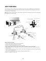
1
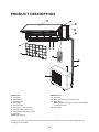
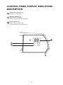
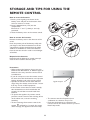
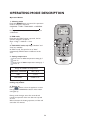
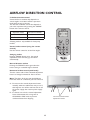
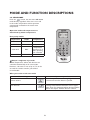
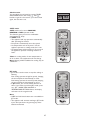
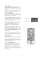
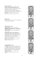
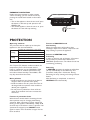
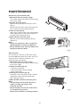
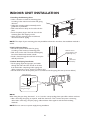
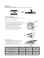
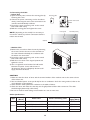
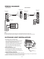
BEFORE USING THE APPLIANCE
To make the most out of your new appliance, please read the user instructions carefully and keep them
handy for future consultation.
SAFETY PRECAUTIONS
• Never block the air inlet or outlet of indoor and
outdoor unit.
• Physically or mentally disabled people, children
and people without any experience with the
product are only allowed to use the appliance if
they have had specific training on how to
operate the appliance by a person responsible
for their security and well-being. The appliance
is not intended for use by disabled people and
very young children without supervision.
• Children should be supervised to ensure that
they do not play with the appliance (including
remote control).
• The Installation and service/repair must be
performed by a qualified technician, in
compliance with the producer's instructions and
following local safety norms. Do not repair or
replace any parts of the appliance unless it is
specifically written in the user instructions.
• Do not pull the power supply cord to remove it
from the socket. Do not twist or press the
power supply cord, and make sure it is not
broken.
• Do not touch the power plug, circuit breaker
and emergency button when your hands are
wet.
• Do not insert your fingers or foreign substances
into the air inlet/outlet of indoor&outdoor unit.
AIR CONDITIONER PRECAUTIONS
Please strictly follow the below instructions:
• Long and direct exposure to cool air might be
harmful to health. It is advisable to set the
louvers in order to avoid direct cool air and
deflect it within the room.
• Upon malfunctioning first turn the appliance off
by pressing the ON/OFF button on the remote
control, then disconnect it from power supply.
• Do not switch the appliance on and off too often
as this can damage the appliance.
• Do not place any objects on the outdoor unit.
• Disconnect the air conditioner from the power
supply if it is to be left unused for a long period
of time or during a thunder/lightning storm.
• This product contains Fluorinated Greenhouse
Gases covered by the Kyoto Protocol, the
refrigerant gas being in a hermetically sealed
system. Refrigerant gas: R410a has a Global
Warming Potential (GWP) 1975.
28
SAFEGUARDING THE ENVIRONMENT
• This appliance has been made of recyclable or
re-usable material. Scrapping must be carried
out in compliance with local waste disposal
regulations. Before scrapping it, make sure to
cut off the mains cord so that the appliance
cannot be re-used.
• For more detailed information on handling and
recycling of this product, contact your local
authorities who deal with the separate collection
of rubbish or the shop where you bought the
appliance.
SCRAPPING OF APPLIANCE
• This appliance is marked according to the
European Directive 2002/96/EC, Waste
Electrical and Electronic Equipment (WEEE).
• By ensuring that this product is disposed of
correctly, you will help to prevent potentially
negative consequences for the environment and
for human health.
• The symbol
on the product or on the
documents accompanying the product indicates
that this appliance should not be treated as
household waste, but must be given to the
appropriate local gathering place where electric
and electronic appliances are stored and
recycled.
SCRAPPING OF PACKAGING
• The packaging can be 100% recycled as
confirmed by the recycling symbol
. The
various parts of the packaging must not be
dispersed in the environment, but must be
scrapped in line with local authority regulations.
29
PRODUCT DESCRIPTION
Outdoor unit
11. Air Intake
12. Pipes and Power Connection Cord
13. Drain Hose
Note: Condensate water drains at COOLING
or DRY operation.
14. Air Outlet
Indoor unit
1. Air Intake
2. Front Panel
3. Display panel
4. Air Outlet
5. Electrical box
6. Emergency control button
7. Vertical Adjustment Louver
8. Horizontal Adjustment Louver
9. Air Filter
10. Remote Control
Images in the user instructions are based on external views of standard models, shape and design vary
according to the model.
30
CONTROL PANEL DISPLAY INDICATORS
DESCRIPTION
Temperature indicator (1)
Displays set temperature.
Running indicator (2)
It lights up during operation.
It flashes during outside unit defrosting.
Timer indicator (3)
It lights up during the set time.
It goes off when timer operation ends.
31
REMOTE CONTROL FUNCTIONS
AND INDICATORS
1.
ON/OFF BUTTON
Starts and/or Stops the appliance by pressing
this button.
2. MODE BUTTON
Used to select the operation mode.
3. FAN BUTTON
Used to select fan speed in sequence auto,
high, medium or low.
4-5. TEMPERATURE BUTTON
Used to select the room temperature. Used
to set time in timer mode and real time clock.
6. 6TH SENSE BUTTON
Sets or cancels 6th sense operation.
7. SWING BUTTON
Stops or starts vertical adjustment louver
swinging and sets the desired up/down airflow
direction.
8. SLEEP BUTTON
Sets or cancels Sleep Mode operation.
9. AROUND U BUTTON
When you press this button, the remote
control transmits signal of the actual room
temperature around itself to the indoor unit
every 10 minutes. Therefore please keep the
remote control in a location where it can
transmit the signal to the indoor unit properly.
Press once to set and press again to cancel.
10. TIMER ON/CLOCK BUTTON
Used to set the current time.
Used to set or cancel the timer on operation.
11 TIMER OFF BUTTON
Used to set or cancel the timer off operation.
q
e
w
u
y
a
h
r
t
i
d
f
o
g
s
12. JET BUTTON
Used to start or stop the fast cooling.
13. DIM BUTTON
Used to turn on or turn off display light on
indoor unit.
14. POWER SAVE BUTTON
Used to start or stop the power save
operation.
15. SUPER SILENT BUTTON
Used to start or stop the super silent
operation. This function is available only on
certain models. Models without this function
don't have the button on the remote control.
INDICATOR SYMBOLS ON RC DISPLAY
Cooling indicator
6th Sense indicator
Dry indicator
Sleep indicator
Fan only indicator
Around U indicator
Heating indicator
Jet indicator
Signal transmission
Auto fan speed
ON
High fan speed
OFF
Medium fan speed
Display set timer
Display current time
Display set temperature
Low fan speed
Power save indicator
Super silent indicator
32
STORAGE AND TIPS FOR USING THE
REMOTE CONTROL
How to insert the batteries
1. Insert a pin and gently press down on the
battery cover and push in the direction of the
arrow to remove, as shown.
2. Insert 2 AAA batteries (1.5V) into the
compartment.
Ensure that "+" and "-" polarity is correctly
positioned.
3. Close the battery cover on the remote control.
How to remove the batteries
Remove the battery cover in the direction of the
arrow.
Press the positive pole of the battery softly with
your fingers, then draw the batteries out of the
compartment. All this should be done by adults,
children are forbidden to remove the batteries
from the remote control in order to avoid danger
of swallow.
Disposal of the batteries
Please discard the batteries as sorted municipal
waste at the accessible collection point.
Precautions
• When replacing the batteries, do not use new
batteries with old batteries, or different types of
batteries as this may cause the remote control
to malfunction.
• If you do not expect to use the remote control
for some time, take the batteries out to prevent
leakage of battery acid in the remote control.
• Operate the remote control within effective
range. Keep the remote control at least 1 meter
from any TV set or HI-FI equipment.
• If the remote control does not work normally,
take the batteries out and reinstall after 30
seconds. If it still does not work install new
batteries.
• To operate the appliance by remote control,
point the remote control at the receiving device
on the indoor unit, to ensure receiving
sensibility.
• To send a message from remote control, the
Signal receptor
• The remote control will operate the air
conditioner at a distance of up to 7m.
• Each time the batteries are replaced in the
remote control, the remote control is pre-set at
Heat Pump mode.
symbol
will flash for 1 second. On receipt
of the message, the appliance will emit a beep.
33
OPERATING MODE DESCRIPTION
Operation Modes:
1. Selecting mode
Each time MODE button is pressed, the operation
mode is changed in sequence:
COOLING → DRY → FAN ONLY → HEATING
↑
Heating mode is not available for cooling only air
conditioners.
2. FAN mode
Each time the "FAN" button is pressed, the fan
speed is changed in sequence:
Auto → High → Medium → Low
↑
At "FAN ONLY" mode, only "High","Medium" and
"Low" are available.
At "DRY" mode, Fan speed is set at "Auto"
automatically, "FAN" button is ineffective in this
case.
4
1
3. Setting temperature
Press once to raise temperature setting by 1
raise °C
Press once to lower temperature setting by 1
lower °C
Range of available set temperature
*HEATING, COOLING
18°C~32°C
DRY
+/-7°C
FAN ONLY
unable to set
*Note: Heating mode is NOT available for
cooling only models.
4. Turning on
Press
button, when the appliance receives
the signal, the RUNNING indicator of the indoor
unit lights up.
During mode changes wait a few seconds and
repeat the operation if the unit does not respond
at once.
When selection the heating operation, air flow will
start after 2-5 minutes.
34
3
2
AIRFLOW DIRECTION CONTROL
5. Airflow direction control
Vertical airflow is automatically adjusted to a
certain angle in accordance with the operation
mode after turning on the unit.
The direction of airflow can be also adjusted to
your own requirement by pressing the "SWING"
button of the remote control.
Operation mode
Direction of airflow
COOLING, DRY
horizontal
*HEATING, FAN ONLY
downward
*Heating mode is only available for heat pump
models.
Vertical airflow control (using the remote
control)
Use the remote control to set the flow angles.
Swinging airflow
Pressing "SWING" button once, the vertical
adjustment louver will swing up and down
automatically.
Desired direction airflow
Pressing the "SWING" button again when the
louvers swing to a suitable angle as desired.
Horizontal airflow control (with hands)
Turn the control rods of the horizontal adjustment
louvers to change horizontal air flow as shown.
Note: The shape of the unit may look different
from that of the air conditioner you have selected.
A - Do not turn the vertical adjustment louvers
manually, otherwise malfunction may occur. If
that happens, turn off the unit first and cut off
the power supply, then restore power supply
again.
B - It is better not to let the vertical adjustment
louver tilt downward for a long time at
COOLING or DRY mode to prevent
condensed water from dripping.
control rod of horizontal
adjustment louvers
35
MODE AND FUNCTION DESCRIPTIONS
6th SENSE MODE
Press the
button, the unit enters 6th sense
mode directly regardless of the unit is on or off.
In this mode, temperature and fan speed are
automatically set based on the actual room
temperature.
Operation mode and temperature are
determined by indoor temperature.
Heat pump models
Indoor
Operation
temperature
mode
21°C or below
HEATING
21°C-23°C
FAN ONLY
23°C-26°C
DRY
Over 26°C
COOLING
Target
temperature
22°C
Room
temperature
decrease 1.5°C
after operating
for 3 minutes
26°C
Button is ineffective in Jet mode.
Note: Temperature, airflow and direction are
controlled automatically in 6th sense mode.
However, a decrease or rise of up to 7°C can be
set with the remote control if you still feel
uncomfortable.
What you can do in 6th sense mode
Your feeling
Uncomfortable because of unsuitable
air flow volume.
Uncomfortable because of unsuitable
flow direction.
button
adjustment procedure
Indoor fan speed alternates among High, Medium
and Low each time this button is pressed.
Press it once, the vertical adjustment louver swings
to change vertical airflow direction. Press it again,
swings stops. For horizontal airflow direction please
refer to the chapter "Airflow direction control".
36
Clock function
You can adjust the real time by pressing TIMER
ON/CLOCK button, then using
and
buttons to get the correct time, press this button
again, the real time is set.
SLEEP mode
SLEEP mode can be set in COOLING,
HEATING or DRY operation mode.
This function gives you a more comfortable
environment for sleep.
In SLEEP mode,
• The appliance will stop operation automatically
after operating for 8 hours.
• Fan speed is automatically set at low speed.
• Set temperature will rise by max 1°C if the
appliance operates in cooling mode for 1 hour.
• Set temperature will decrease by 3°C at most if
the appliance operates in heating mode for 3
hours.
*Note: In cooling mode, if room temperature is
26°C or above, set temperature will not change.
Note: Heating is NOT available for cooling only air
conditioner.
JET mode
• JET mode is used to start or stop fast cooling or
Heating.
Fast cooling operates at high fan speed, changing
the set temperature automatically to 18°C.
Fast heating operates at auto fan speed,changing
the set temperature automatically to 32 °C.
• In JET mode, you can set airflow direction or
timer. If you want to quit from JET mode, press
any - JET , MODE, FAN, ON/OFF or
TEMPERATURE SETTING button, the display
will return to the original mode.
Note:
• SLEEP and 6th Sense buttons are not available in
JET mode.
• The appliance will continue working in JET mode
if you don't quit from it by pressing any of the
buttons mentioned.
37
Timer function
It is convenient to set the timer on by pressing the
TIMER ON/CLOCK button to achieve a
comfortable room temperature at the time you get
home.
You can also set timer off by pressing the TIMER
OFF button to enjoy a good sleep at night.
How to set TIMER ON
TIMER ON/CLOCK button can be used to set the
timer programming as wished in order to switch on
the appliance at your desired time.
i) Press TIMER ON/CLOCK button for 3 seconds,
when "ON 12:00" flashes on the LCD, then you
can press the
or
buttons to select your
desired time for appliance on.
Increase
ON
Decrease
Press the
or
button once to increase or
decrease the time setting by 1 minute.
Press the
or
button for 5 seconds to
increase or decrease the time setting by 10
minutes.
Press the
or
button for a longer time to
increase or decrease the time by 1 hour.
Note: If you don't see the time in 10 seconds after
you press TIMER ON/CLOCK button, the remote
control will exit the TIMER ON mode
automatically.
ii) When your desired time displayed on LCD,
press the TIMER ON/CLOCK button and confirm
it.
A "beep" can be heard.
"ON" stops flashing.
The TIMER indicator on the indoor unit lights up.
iii) After the time set displayed for 5 seconds the
clock will be displayed on the LCD of the remote
control instead of set timer.
How to cancel TIMER ON
Press the TIMER ON/CLOCK button again, a
"beep" can be heard and the indicator disappears,
the TIMER ON mode has been canceled.
Note: It is similar to set the TIMER OFF, you can
make the appliance switch off automatically at your
desired time.
38
Around U function
When you press this button,
will display,
remote control transmits the actual room
temperature around it to the indoor unit, and the
appliance will operate according to this
temperature to let you feel more comfortable.
Please keep the remote control in a location where
it can transmit the signal to the indoor unit
properly.
Press once to set and press again to cancel.
DIM function
Press this button to turn on or turn off display light
on indoor unit control panel.
POWER SAVE function
POWER SAVE mode can be available in
COOLING, HEATING, DRY and FAN ONLY
operation mode.
When pressing this button,
will display on
remote control.
POWER SAVE function under COOLING,
HEATING and DRY mode, the appliance will set
the temperature at 25°C with low fan speed.
POWER SAVE function under FAN ONLY mode:
the appliance will set at low fan speed.
Change mode or press the power save button
again to cancel this function.
Note: Fan speed and temperature can not be
adjusted under this mode.
SUPER SILENT function
Press
button to let the unit operate at low
noise level to get a quiet and comfortable room
environment.
will display on remote control.
Note: Super silent function
will be off when
pressing MODE button, or pressing SUPER
SILENT button again.
This function may not be available on some
models.
39
EMERGENCY OPERATION
Under emergency situation or when remote
control is missing, you can control the unit by
pressing the on/off swith located on the indoor
unit.
• Turn on the appliance: when the unit is off, press
this button, it will start up and operate in 6th
SENSE mode.
• Turn off the appliance: when the unit is on, press
this button, the unit will stop working.
on/off switch
PROTECTION
Operating condition
The protective device maybe trip and stop the
appliance in the cases listed below.
Features of COOLING mode
Anti-freezing
When the temperature of the indoor heat
exchanger drops to 0° or below, compressor will
stop working to protect the appliance.
Outdoor air temperature is over 24°C
Outdoor air temperature is below -10°C
Room temperature is over 27°C
Outdoor air temperature is over *43°C
Cooling
Room temperature is below 21°C
Dehumidifying Room temperature is below 18°C
Heating
Features of HEATING mode
Preheating
In order to prevent cool air blowing, 2-5 minutes
are necessary to preheat the indoor unit at
HEATING operation start. The indoor fan will not
work during preheating.
*For Tropical (T3) Climate condition models, the
temperature point is 52°C instead of 43°C.
If the air conditioner runs in COOLING or DRY
mode with door or window opened for a long
time when relative humidity is above 80%, dew
may drip down from the outlet.
Defrosting
In HEATING operation the appliance will defrost
(de-ice) automatically to raise efficiency. This
procedure usually lasts 6-10 minutes. During
defrosting, fan stops running and running indicator
flashes.
After defrosting is completeed, it returns to
HEATING mode automatically.
Noise pollution
• Install the appliance at a place that can bear its
weight in order to operate more quietly
• Install the outdoor unit at a place where the air
discharged and the operation noise would not
disturb your neighbours.
• Do not place any obstacles in front of the air
outlet of the outdoor unit lest it increases the
noise level.
Features of protection device
Wait at least 3 minutes before restarting the unit
after operation stops or changing mode during
operation. After connecting to power supply and
turning on the appliance immediately, a delay of 20
seconds may occur before it starts to operate. If all
operation has stopped, press ON/OFF button
again to restart. Timer should be set again if it has
been cancelled.
40
MAINTENANCE
Clean front panel of Indoor Unit
1. Disconnect from the power supply
Turn off the appliance first before disconnecting
from power supply.
2. Remove the front panel
Open the front panel as shown by the arrow
(Fig. A).
Pull the slots at the side of the front panel with
force to take out the front panel (Fig. B).
3. Clean the front panel
Wipe it with a soft and dry cloth. Use lukewarm
water (below 40°C) to clean if the appliance is
very dirty. After cleaning let it dry.
4. Refit and close the front panel.
Refit and close the front panel by pushing it
downward.
Note:
• Do not use substances such as gasoline or
polishing powder to clean the appliance.
• Do not sprinkle water onto the indoor unit
Dangerous! Electric shock!
Fig. A
Fig. B
Clean Air filter
It is necessary to clean the air filter after using it
for about 100 hours.Clean the air filter every two
weeks if the air conditioner operates in an
extremely dusty environment.
1. Disconnect from the power supply
Turn off the appliance first before disconnecting
from power supply.
2. Take out air filter (Fig. C).
1. Open the front panel.
2. Press the handle of the filter gently.
3. Slide out the filter.
3. Cleaning the air filter (Fig. D)
If the filter is very dirty, clean it with a solution
of lukewarm water and neutral detergent.
After cleaning let it dry.
4. Refit the filter and close the front panel.
Note:
• To avoid injury, do not touch the fins of
indoor unit with your fingers after
removing the filter.
• Do not attempt to clean the inside of the
air conditioner by yourself.
• Do not clean the filter in washing machine.
Fig. C
Fig. D
41
TROUBLESHOOTING
Operation problems are often due to minor causes, please check and refer to the
following chart before contacting the service. This may save time and unnecessary
expenses.
Trouble
Analysis
Does not run
• Is the protection device or fuse blown?
• Please wait for 3 minutes and start again, protection device may be preventing
unit to work.
• Are the remote control batteries low?
• Is the plug not properly plugged?
No cooling or
heating air
•
•
•
•
Ineffective control
• Has there been a strong interference (from excessive static electricity discharge,
power supply voltage abnormality)? Note that operation will be abnormal, in this
case unplug from the power supply and re-plug after 2-3 seconds.
Does not operate
immediately
• 3 minute delay will occur when changing mode during operation.
Peculiar smell
• This smell may come from another source such as furniture, cigarette etc, which
is sucked in the unit and blown out with the air.
A sound of running
water
• Normal behaviour caused by the flow of refrigerant in the air conditioner.
• Defrosting sound in heating mode.
Cracking sound
• The sound may be generated by the expansion or contraction of the front panel
due to temperature changes.
Mist sprays from
the outlet
• Mist is present in the room with low temperature? Normal behaviour due to
cool air discharged from indoor unit during COOLING or DRY operation
mode.
Running indicator
flashes but indoor
fan stops.
• The unit is shifting from heating mode to defrost. The indicator will light off and
return to heating mode.
Is the air filter dirty?
Are the intakes and outlets of the air conditioner blocked?
Is the temperature set properly?
Are doors or windows open?
Note: If the problems still have, turn off the appliance and disconnect from power supply,
then contact the nearest Whirlpool Authorized Service Center. Do not attempt to move,
repair, disassemble, or modify the appliance by yourself.
42
INSTALLATION INSTRUCTIONS
Installation diagram
Distance from ceiling
should be over 200mm
Distance from wall
should be over 50mm
Distance from the wall
should be over 50mm
Indoor unit
Distance from floor
should be over 2500mm
Outdoor unit
Air intake distance from
the wall should be over
250mm
Air intake distance from
the wall should be over
250mm
Ai
shor out
uld let
be dist
ov anc
er e f
50 rom
0m
m the
wa
ll
Over 250mm
NOTE: The figure above is only a simple presentation of the unit, it may not match the external
appearance of the product you purchased. Installation must be performed in accordance with the national
wiring standards by authorized service people only.
43
Select the best location
Location for Installing Indoor Unit
• Where there is no obstacle near the air outlet
and air can be easily blown to every corner of
room.
• Where piping and wall hole can be easily
arranged.
• Observe the required distance from ceiling and
wall according to the installation diagram.
• Where the air filter can easily be removed.
• Keep the unit and remote control 1m or more
from television, radio etc.
• To prevent the effects of a fluorescent lamp,
keep the unit as far as possible from it.
• Do not put anything near the air inlet that could
obstruct it.
• In a place that can bear the weight and will not
increase operating noise and vibrations.
• The indoor unit is not suitable to be installed in
areas used for laundry.
Indoor unit
Height should
be less than 5m
Pipe length is
3~15 meters
Location for Installing Outdoor Unit
• Install in a convenient and well-ventilated place.
• Avoid installing it where flammable gas could
leak.
• Observe the required distance from the wall
according to the installation diagram.
• The distance between Indoor and outdoor unit
should be 5 meters and can go up to maximum
15 meters with additional refrigerant charge.
• Do not install the outdoor unit in a dirty or
greasy place, near a vulcanization gas exit.
• Avoid installing it at the roadside where it could
be soiled with muddy water.
• A fixed base where operating noise will not
increase.
• Where the air outlet is not obstructed.
• The installation position shall be able to
withstand the weight and vibration of the
outdoor unit and ensure safe installation;
• Where drained water does not become any
problem.
Outdoor unit
Outdoor unit
Height should be less
than 5m
Pipe length is
3~15 meters
Indoor unit
Model
Standard tubing
Length (m)
Limit of Tubing
Length (m)
9K/12K/18K
5
15
44
Limit of Elevation Required extra
Difference H (m) refrigerant when
the connecting
tube over 5m
(g/m)
5
20
INSTALLATION SERVICE
Before installation
1. Please read this manual carefully before
installation.
2. The appliance must be installed according to
national wiring rules and according to this
manual by qualified technicians.
3. Any change of installation position must be
handled by professionals;
4. Check the product to verify that it has not been
damaged before installation.
5. Mount with the lowest moving parts of indoor
unit at least 2.5m above floor or grade Level.
6. After installing, the consumer must operate the
appliance correctly according to this manual,
keep a suitable storage for maintenance and
move of it in the future.
SAFETY PRECAUTION
1. The power supply must be of rated voltage
with special circuitry for the appliance. The
normal operating range of voltage is
90%~110% of rated voltage. The diameter of
the power cord must comply with
requirements.
2. The user power supply shall have a reliable
grounding terminal. It is prohibited to connect
the grounding wire to the following items: 1)
Water Supply Pipe 2) Gas Pipe 3) Sewage Pipe
4) Other positions that are considered unsafe
3. Ensure safe grounding and a grounding wire
connected with the special grounding system of
the building, installed by professionals. The
appliance must be fitted with electrical leakage
protection switch and an air switch with
sufficient capacity (Refer to the following
chart). The air switch must also have a
magnetic and a thermal tripping function to
ensure protection in case of short-circuit and
overload.
Type
Inverter
Model
Required Capacity of air
break switch
9k
16A
12k
16A
18k
25A
24k
32A
6. An all-pole disconnection switch having a
contact separation of at least 3mm in all poles
should be connected in fixed wiring.
7. Risk of electric shock can cause injury or death:
Disconnect all electric power supplies before
servicing.
8. The connection of power cord and the cable
connection between indoor unit and outdoor
unit shall be in accordance with the wiring
diagram attached on the appliance.
9. Once installation is completed, the electric
components must not be accessible to the
users.
10. Use two or more people to move and install
the appliance to avoid excessive weight hazard.
11. After unpacking the air conditioner, keep all
packaging materials well out of the reach of
children.
12. According to the character of refrigerant
(R410a), the pressure of the tube is very high,
so be sure to careful when you install and
repair the appliance.
4. Make sure that the power supply cord is long
enough to allow the right connection. Do not
use any extension cord for power supply.
5. If the supply cord is damaged, it must be
replaced by the manufacturer or its service
agent or a similarly qualified person in order to
avoid a hazard;
45
INDOOR UNIT INSTALLATION
1. Installing the Mounting Plate
• Select a location to install the mounting plate
according to the indoor unit location and piping
direction.
• Adjust the mounting plate horizontally with a
gradienter or plumb line.
• Drill holes 32mm in deep on the wall to fix the
plate.
• Insert the plastic plugs in the hole, then fix the
mounting plate with tapping screws.
• Check that the mounting plate is well fixed.
Then drill a hole for piping.
Tapping screw
Mounting plate
NOTE: The shape of your mounting plate may be different from the one above, but installation method is
similar.
Wall hole sleeve
(hard polythene tube
prepared by user)
Outdoor
Indoor
2. Drill a Hole for Piping
• Decide the position of the hole for piping
according to the location of mounting plate.
• Drill a hole on the wall. The hole should slightly
be inclined downward toward outside.
• Install a sleeve through the wall hole to keep the
wall tidy and clean.
5mm
(downward
inclination)
3. Indoor Unit Piping Installation
• Fit the piping (liquid and gas pipe) and cables
through the wall hole from outside or fit them
from inside after completing indoor piping and
cables connections so as to connect to outdoor unit.
• Decide whether saw off the plastic part in accordance with the piping direction (as shown below).
Piping direction
trough
4
Unloading
piece
Saw the unloading piece off
along the trough
1
3
2
NOTE:
When fixing the pipe along directions 1, 2 or 4, saw the corresponding plastic part off the indoor unit base.
• After connecting the piping as required, install the drain hose. Then connect the power connecting
cable. After connecting, wrap the piping, cable and drain hose together with thermal insulating
materials.
NOTE: Do not connect to power supply during installation.
46
IMPORTANT:
Piping Joints Thermal Insulation:
Wrap the piping joints with thermal insulating materials and then wrap with a vinyl tape.
Wrapped with vinyl type
Thermal insulation
Thermal Insulation piping:
a. Place the drain hose under the piping.
b. Insulation material: polythene foam over 6mm in thickness.
NOTE: Drain hose is prepared by user.
Large pipe
• Drain hose should point downward for easy drain Power connecting
flow. Do not twist the drain pipe, leave it sticking cable
out or waving around, do not immerse the end in
water. If an extension drain hose is connected to the
drain pipe, make sure to be thermally insulated
when passing it through the indoor unit.
• When the piping is directed to the right, piping,
power cable and drain hose should be thermally
insulated and fixed at the rear of the unit.
Thermally
insulated tube
Small pipe
Drain hose
(prepared by user)
Piping Connection:
a. Connect indoor unit pipes with two wrenches. Pay
special attention to the torque allowed as shown
below to prevent the pipes, connectors and flare
nuts from being deformed and damaged.
b. At first fingers-tighten them, then use the wrenches.
Pipe size
Torque
Nut width
Min. thickness
Liquid Side (1/4 inch)
1.5~2kg.m
17mm
0.5mm
Liquid Side (3/8 inch)
3.1~3.5kg.m
22mm
0.6mm
Gas Side (3/8 inch)
3.1~3.5kg.m
22mm
0.6mm
Gas Side (1/2 inch)
5.0~5.5kg.m
24mm
0.8mm
Gas Side (5/8 inch)
6.0~6.5kg.m
27mm
0.8mm
47
4. Connecting the Cable
• Indoor Unit
1) Open the front panel, remove the covering plate by
loosening the screw.
2) Connect the power connecting cord to the indoor
unit by connecting the wires to the terminals on the
control board individually as follows.
3) Secure the power connecting cord on the control
board with cable clamp.
4) Refit the covering plate and tighten the screw.
Covering plate
Power Connection
Cable
Front panel
NOTE: (depending on the model) It is necessary to
remove the cabinet to perform connections with the
indoor unit terminal.
Terminal (inside)
Cabinet
Indoor unit
• Outdoor Unit
1) Remove the access door from the unit by loosening
the screw. Connect the wires to the terminals on
the control board individually in accordance with
the indoor unit connection.
2) Secure the power connecting cord on the control
board with cable clamp.
3) Refit the access door in the original position and
tighten the screw.
4) Use a recognized circuit breaker for 24K model
between the power source and the unit. A
disconnecting device to adequately disconnect all
supply lines must be fitted.
Access door
Terminal
(inside)
Outdoor unit
CAUTION:
1. Make sure that the colour of wires and the terminal number of the outdoor unit are the same as those
of the indoor unit.
2. Use an individual power circuit specifically for the air conditioner. As for the wiring method, refer to the
circuit diagram on the appliance.
3. Check that the cable specification conforms to the table as follows.
4. Check the wires and make sure that they are all tightly fastened after cable connection. The cable
should be tighly fastened by cable clamp.
5. Be sure to install an earth leakage circuit breaker in a wet or moist area.
Cable Specifications
Type
Inverter
Capacity
(Btu/h)
Power cord
Power connecting cable
Main power
supply (Note)
9k
H05VV-F, 3G x 1.0 mm² / 1.5 mm²
H07RN-F, 4G 1.0 mm² / 1.5 mm²
To indoor
12k
H05VV-F, 3G x 1.0 mm² / 1.5 mm²
H07RN-F, 4G 1.0 mm² / 1.5 mm²
To indoor
18k
H07RN-F, 3G 2.5 mm²
H07RN-F, 4G 1.5 mm²
To indoor
24k
H07RN-F, 3G 2.5 mm²
H07RN-F, 4G 2.5 mm²
To indoor
48
WIRING DIAGRAM
• 18K/24K Models
• 9K/12K Models
Outdoor unit
Indoor unit
Terminal
Indoor unit
Terminal
Outdoor unit
Terminal
Terminal
Yellow/Green
Yellow/Green
Blue (Gray)
Yellow/Green
Blue (Gray)
1(N)
Brown
2(L)
3(SI)
Brown
Power connecting cord
1(N)
2(L)
Black
3(SI)
Black
Yellow/Green
Blue (Gray)
Blue (Gray)
Brown
Brown
Power connecting
cord
Black
Black
BN
BU
Evaporator
YE/GN
YE/GN
Indoor unit control board
BN
AC L-IN
BU
Power supply
AC N-IN
Power supply
Note:
For 9k, 12k models, the power supply are connected from indoor unit with a plug.
For 18k, 24k models, the power supply are connected from indoor unit with a circuit breaker.
OUTDOOR UNIT INSTALLATION
1. Install Drain Port and Drain Hose
The condensate drains from the outdoor unit when
the unit operates in heating mode. In order not to
disturb your neighbours and protect the
environment, install a drain port and a drain hose to
direct the condensate water. Just install the drain
port on the chassis of the outdoor unit, then
connect a drain hose to the port as shown in the
figure on the right .
Chassis
2. Install and Fix Outdoor Unit
Drain port
Fix with bolts and nuts tightly on a flat and strong
floor. If installed on the wall or roof, make sure to
fix the supporter well to prevent it from shaking due
Drain hose
(prepare by user)
to serious vibration or strong wind.
3. Outdoor Unit Piping Connection
• Remove the valve caps from the 2-way and 3-way valve.
• Connect the pipes to the 2-way and 3-way valves separately according to the required torque.
4. Outdoor Unit Cable Connection (see previous page)
49
AIR PURGING
Air containing moisture remaining in the refrigeration cycle may cause a malfunction on the compressor.
After connecting the indoor and outdoor units, evacuate air and moisture from refrigerant cycle using a
vacuum pump, as shown below.
Note: Because the system pressure is high and also to protect the environment, be sure not to discharge
the refrigerant to the air directly.
Connect to indoor unit
3-way valve diagram
Open position
Vacuum pump
Connect to outdoor unit
Spindle
Needle
r unit
Indoo
Service port cap
Refrigerant flow direction
2-way valve
Valve core
3-way valve
(6) Open 1/4 turn
(7) Turn to fully open the valve
(7) Turn to fully
open the valve
Valve cap
(1) Turn
(1) Turn
Service port
(8) Tighten
(8) Tighten
(2) Turn
(8) Tighten
Valve cap
How to Purge Air Tubes:
1. Unscrew and remove caps from 2 and 3-way valves.
2. Unscrew and remove cap from service valve.
3. Connect vacuum pump flexible hose to the service valve.
4. Start vacuum pump for 10-15 minutes until it reaches an absolute vacuum of 10 mm Hg.
5. With vacuum pump still running close the low pressure knob on vacuum pump manifold. Then stop
vacuum pump.
6. Open 2-way valve 1/4 turn, then close it after 10 seconds. Check tightness of all joints using liquid soap
or an electronic leak detector.
7. Turn 2 and 3-way valves stem. Disconnect vacuum pump flexible hose.
8. Replace and tighten all valve caps.
50
AFTER SALES SERVICE
If repair work has to be carried out, contact the
Customer Care Centre (Use of original spare
parts and a proper repair is guarenteed).
You will need to present the original invoice.
Failure to comply with these instructions
could compromise the safety and quality of
your product.
Before contacting the Customer Care Centre:
1. Try to solve the problem yourself based on the
descriptions given in the "Troubleshooting".
2. Turn the appliance off and restart it to see if the
fault persists.
If after carrying out the above checks, the
fault persists, contact the Customer Care
Centre.
Please give:
• a short description of the fault;
• the exact model of the air conditioner;
• the service number (this is the number found
below the word Service on service sticker which
is located on the side or on the bottom of the
indoor unit).
The service number can also be found in the
warranty booklet;
• your full address;
• your telephone number.
51