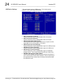
1
IOS-7400 Industrial Computer with 1.6MHz Intel® Atom processor USER’S MANUAL ACROMAG INCORPORATED 30765 South Wixom Road P.O. BOX 437 Wixom, MI 48393-7037 U.S.A. Tel: (248) 295-0310 Fax: (248) 624-9234 Email: [email protected] Web: http://www.acromag.com Copyright 2010-2011, Acromag, Inc., Printed in the USA. Data and specifications are subject to change without notice. 8500-879-D13C019 2 I/O SERVER User’s Manual Industrial PC __________________________________________________________________ TABLE OF CONTENTS IMPORTANT SAFETY CONSIDERATIONS You must consider the possible negative effects of power, wiring, component, sensor, or software failure in the design of any type of control or monitoring system. This is very important where property loss or human life is involved. It is important that you perform satisfactory overall system design and it is agreed between you and Acromag, that this is your responsibility. 1.0 General Information The information in this manual may change without notice. Acromag makes no warranty of any kind with regard to this material, including, but not limited to, the implied warranties of merchantability and fitness for a particular purpose. Further, Acromag assumes no responsibility for any errors that may appear in this manual and makes no commitment to update, or keep current, the information contained in this manual. No part of this manual may be copied or reproduced in any form without the prior written consent of Acromag, Inc. KEY FEATURES………………………………………... BOARD CONTROL SOFTWARE…………………….. SIGNAL INTERFACE PRODUCTS…………………… 4 5 5 2.0 PREPARATION FOR USE UNPACKING AND INSPECTION…………………….. BOARD CONFIGURATION……………………………. Default Hardware Configuration………………. IOS MODULE INSTALLATION……………………….. FRONT PANEL FIELD I/O CONNECTOR…………… 10/100 Ethernet Connection……………………. VGA Video Connection………………………….. Serial Connections………………………………. USB Ports………………………………………….. Audio Jacks……………………………………….. IOS Modules Field I/O…………………………… REAR PANEL FIELD CONNECTORS……………….. ® CompactFlash …………………………………… Power & LEDs…………………………………….. OPTIONAL 2.5” DRIVE………………………………… 2.5” IDE Drive Installation………………………. NON-ISOLATION CONSIDERATIONS………………. 6 6 6 7 8 8 9 9 10 10 11 11 11 12 12 12 13 3.0 BIOS MAIN MENU……………………………………………... Passwords………………………………………… STANDARD CMOS FEATURES……………………… ADVANCED BIOS FEATURES……………………….. ADVANCED CHIPSET FEATURES………………….. Integrated Peripherals………………………………… ONCHIP IDE DEVICE…………………………………... ONBOARD DEVICE……………………………………. SUPERIO DEVICE……………………………………… USB DEVICE SETTINGS………………………………. POWER MANAGEMENT SETUP…………………….. PnP/PCI CONFIGURATIONS…………………………. PC HEALTH STATUS………………………………….. FREQUENCY/VOLTAGE CONTROL………………… BIOS RECOVERY PROCEDURE…………………….. 14 15 16 17 19 20 21 22 23 24 25 25 26 26 27 ________________________________________________________________________ Acromag, Inc. Tel:248-295-0310 Fax:248-624-9234 Email:[email protected] http://www.acromag.com I/O SERVER User’s Manual Industrial PC ___________________________________________________________________ TABLE OF CONTENTS 4.0 SYSTEM OVERVIEW I/O Server Internal Ethernet Switch………………… I/O Server Power Supply Fuse………………………. IDE (PATA) Hard Drive Connections……………….. MLC vs. SLC Flash…………………………………….. CARRIER BOARD OVERVIEW………………………. PCI Bus Interface………………………………… IOS Carrier Board Registers…………………… IOS Logic Interface………………………………. IOS Carrier Board Clock Circuitry…………….. PCI Interrupts……………………………………... IOS Modules Power-On Reset…………………. IOS Modules Power Supply Fuses……………. 3 28 28 28 29 29 29 29 30 30 30 30 30 5.0 ACCESSING THE IOS CARRIER PCI Configuration Address Space………………….. PCI Configurations Transactions…………………… PCI Configuration Registers…………………………. MEMORY MAP………………………………………….. Carrier Status/Control Register……………….. IOS Interrupt Pending Register………………... Clock Control Register………………………….. IOS Module Interrupt Space……………………. IOS Module ID Space……………………………. IOS Module I/O Space…………………………… IOS Module Memory Space…………………….. GENERATING INTERRUPTS…………………………. 31 31 31 32 34 36 36 36 37 37 37 37 6.0 SERVICE AND REPAIR SERVICE AND REPAIR ASSISTANCE……………… PRELIMINARY SERVICE PROCEDURE……………. WHERE TO GET HELP………………………………… 38 38 38 7.0 SPECIFICATIONS PHYSICAL……………………………………………….. ELECTRICAL……………………………………………. ENVIRONMENTAL……………………………………... 39 39 42 APPENDIX IOS-7400 BLOCK DIAGRAM…………………………. IOS-CARRIER FUSE LOCATION DRAWING………. SYSTEM I/O PORTS MEMORY MAP………………... SYSTEM IRQ ASSIGMENTS………………………….. SYSTEM 1MB MEMORY MAP………………………... 44 45 46 47 48 Trademarks are the property of their respective owners. ________________________________________________________________________ Acromag, Inc. Tel:248-295-0310 Fax:248-624-9234 Email:[email protected] http://www.acromag.com 4 I/O SERVER User’s Manual Industrial PC __________________________________________________________________ 1.0 GENERAL INFORMATION The I/O Server Industrial computer provides users with a mobile rugged computing option with a wide variety of integrated I/O connections. The ® IOS-7400 has a built in 1.6MHz Intel Atom processor with 1GB of DDR2 RAM and features two Ethernet ports, four USB ports, audio, video, and two COM ports. The I/O Server’s built in carrier card allows for users to select up to four plug-in I/O modules that provide a wide range of industrial input/output including digital, analog inputs, analog outputs, counter-timer modules, and a module with a customer programmable FPGA. All these items are packaged in a small rugged fanless form factor with an extended operating temperature range. Refer to the table below for available I/O Server models. Table 1.1: I/O Server Basic Models MODEL Front I/O Type Front I/O Connector OPERATING TEMPERATURE RANGE ® IOS-7200 IOS-7400 AMD Geode LX800 500MHz 512MB DDR ® Intel Atom N270 1.6GHz 1GB DDR2 -30C to +75C -30C to +75C Both models are available with a -WIN suffix. These versions include an ® ® 8GB Industrial CompactFlash with a Windows Embedded Standard image and license. The I/O Server and IOS modules are suitable for use in Class I, Division 2, Groups A, B, C, and D hazardous locations or non-hazardous locations only. The following models are the available IOS modules, which are cULus listed and can only be used in the IOS-7200 & IOS-7400 I/O Server. All IOS models operate at the full operating temperate of the base I/O Server unit. Refer to the individual manuals for each of the IOS modules for further information. Models: IOS-220-8, IOS-220-16, IOS-231-8, IOS-231-16, IOS-320, IOS330, IOS-341, IOS-EP201, IOS-EP202, IOS-EP203, IOS-EP204, IOS-520, IOS-521, IOS-560, IOS-560-I, IOS-571, IOS-572, IOS-408, IOS-409, IOS440-2, IOS-445, IOS-470, IOS-482, IOS-483, and IOS-484. KEY FEATURES Rugged Embedded PC – The IOS-7400 includes an embedded ® 1.6GHz Intel Atom processor with 1GB of installed DDR2 RAM. This is a low power fanless design with high-reliability operation that is shock and vibration resistant. High-density, Interchangeable I/O – Each I/O server supports up to four separate IOS module to enable mix and match flexibility for a wide variety of field I/O. Extended Temperature Range – The IOS-7400 has a wide operating temperature range even with four IOS modules installed under a full system load. ________________________________________________________________________ Acromag, Inc. Tel:248-295-0310 Fax:248-624-9234 Email:[email protected] http://www.acromag.com I/O SERVER User’s Manual Industrial PC ___________________________________________________________________ Standard Peripheral Connection – The I/O Server provides two standard RS232 serial ports, two switched Ethernet ports, four USB, audio, and video ports for peripheral connections. Windows Embedded Standard – The IOS-7400-WIN model includes ® ® a Windows Embedded Standard (based upon Windows XP SP3) ® image installed on an 8GB Industrial CompactFlash . Windows Drivers – The IOSSW-DEV-WIN software support package contains low-level driver and Windows 32 Dynamic Link Libraries that are compatible with many programming environments. Linux Drivers – The IOSSW-API-LNX software support package contains the Linux OS Getting Started Guide and IOS modules Linux device drivers are available from Acromag. Wide Operating Voltage – The I/O Server has a 9-32V DC input. External isolated AC/DC power supplies are available from Acromag. 5 ® ® The IOS-7400-WIN model includes an 8GB industrial CompactFlash ® that contains a licensed Microsoft Windows Embedded Standard image. The image includes many of the standard Windows components and is suitable for the majority of customer applications. This allows users to quickly develop their application in a familiar environment. Device drivers for Acromag IOS modules are sold separate as described in the following section. BOARD CONTROL SOFTWARE ® Windows Embedded Standard Acromag provides a software product (sold separately) to facilitate the ® development of Windows Embedded Standard applications interfacing with I/O Server Modules installed on Acromag Industrial I/O Server systems. This software (Model IOSSW-DEV-WIN) consists of low-level driver and Windows 32 Dynamic Link Libraries (DLLS) that are compatible with a number of programming environments including Visual C++, Visual Basic.NET, Borland C++ Builder and others. The DLL functions provide a high-level interface to the IOS carrier and modules eliminating the need to perform low-level reads/writes of registers, and the writing of interrupt handlers. IOS MODULE Win32 DRIVER SOFTWARE Acromag provides a software product (sold separately) consisting of IOS module Linux support software. This software (Model IOSSW-APILNX) is composed of Linux libraries designed to support applications accessing I/O Server Modules installed on Acromag Industrial I/O Server systems. The software is implemented as a library of “C” functions which link with existing user code. IOS MODULE LINUX SOFTWARE Acromag provides the following interface products for the I/O Server. Note that all connections to field signals are made through the IOS carrier board which passes them to the individual IOS modules. SIGNAL INTERFACE PRODUCTS Model 5028-438: SCSI-2 50 Pin Shielded Cable. A round 50-pin cable with SCSI-2 plug connectors at both ends for connecting I/O Server to Model 5028-378 termination panels. CABLES ________________________________________________________________________ Acromag, Inc. Tel:248-295-0310 Fax:248-624-9234 Email:[email protected] http://www.acromag.com 6 I/O SERVER User’s Manual Industrial PC __________________________________________________________________ TERMINATION PANEL Refer to Acromag’s website www.acromag.com for more information on compatible products. 2.0 PREPARATION FOR USE UNPACKING AND INSPECTION Model 5028-378: DIN-rail mountable panel provides 50 screw terminals for universal field I/O termination. Connects to Acromag IOS-7400 via SCSI-2 50 pin shielded cable (Model 5028-438) Upon receipt of this product, inspect the shipping carton for evidence of mishandling during transit. If the shipping carton is badly damaged or water stained, request that the carrier's agent be present when the carton is opened. If the carrier's agent is absent when the carton is opened and the contents of the carton are damaged, keep the carton and packing material for the agent's inspection. For repairs to a product damaged in shipment, refer to the Acromag Service Policy to obtain return instructions. It is suggested that salvageable shipping cartons and packing material be saved for future use in the event the product must be shipped. This board is physically protected with packing material. However, it is recommended that the unit be visually inspected for evidence of mishandling prior to applying power. Refer to the specifications for loading and power requirements. Be sure that the system power supplies are able to accommodate the power requirements of the system board, plus the installed IOS modules, within the voltage tolerances specified. ENVIRONMENTAL CONSIDERATIONS The I/O Server is designed to operate in areas with little or no air circulation. However to facilitate conduction cooling of the unit, it must be orientated such that heat fins are on top or the side of the device (in reference to the floor). Orientating the object with the heat fins facing downward may cause the internal temperature to rise above the maximum operating temperature. BOARD CONFIGURATION Remove power from the system before installing any IOS modules, cables, and/or field wiring. Default Hardware Configuration Upon receipt, customer can use the I/O Server once an appropriate operating system has been installed. Warnings WARNING – EXPLOSION HAZARD – Do not disconnect equipment unless power has been removed or area the area is known to be nonhazardous. WARNING – EXPLOSION HAZARD – Substitution of any components may impair suitability for Class I, Division 2. WARNING – EXPLOSION HAZARD – The area must be known to be non-hazardous before servicing/replacing the unit and before installing. ________________________________________________________________________ Acromag, Inc. Tel:248-295-0310 Fax:248-624-9234 Email:[email protected] http://www.acromag.com I/O SERVER User’s Manual Industrial PC ___________________________________________________________________ To install the IOS modules, first remove all power from the device. The IOS Carrier is not hot swappable. Failure to power down the I/O Server prior to removing the IOS carrier will result in board damage. To remove the IOS Carrier turn the two Captive screws counterclockwise on the front panel until they are free of the enclosure. Then pull the IOS Carrier out from the enclosure. The IOS Carrier slides out on guide rails. Note that some force is required to remove the IOS Carrier, especially if IOS modules are already installed. Refer to the picture below. 7 IOS Module Installation DANGER: The IOS Carrier is NOT hot swappable. Power must be removed from the device before removing the IOS Carrier. Figure 2.1: IOS Carrier Removal. To remove the Carrier turn the 2 captive screws to the left until they are detached from the faceplate. Then pull out the IOS carrier. IOS Carrier Captive Screws (2x) Once the IOS Carrier has been removed install the IOS modules onto the Carrier board. The modules are keyed to avoid incorrect installation. No further hardware is required to secure the IOS modules. The four slots are marked as A, B, C or D. Note the slot location of each module as this information is necessary to access the IOS module from software. Refer to Section 4.0 for further information on accessing the IOS modules. Figure 2.2a: IOS Module Installation To install the IOS Modules firmly press them into any of the four available slots. IOS Modules are keyed to avoid incorrect installation. ________________________________________________________________________ Acromag, Inc. Tel:248-295-0310 Fax:248-624-9234 Email:[email protected] http://www.acromag.com 8 I/O SERVER User’s Manual Industrial PC __________________________________________________________________ Figure 2.2b: IOS Module Installation To install the IOS Modules firmly press them into any of the four available slots. IOS Modules are keyed to avoid incorrect installation. Note: Inserting the IOS Carrier may require considerable force. After IOS module installation, slide the IOS Carrier back into the enclosure via the guide rails until the front panel is flush against the faceplate. Note that considerable force is required to push the carrier and the mating connector together. Once the panel is flush, turn the two captive screws clockwise until tight. Front Panel Field I/O Connector The I/O Server front panel has many of the same connections as a standard personal computer. This includes Ethernet, audio, video, USB, and serial ports. Access to these ports is obtained though the Operating System. The front panel also provides user access to the IOS carrier board which contains the IOS modules as well as the corresponding I/O connections (ports). Information regarding these ports is contained in the following section. 10/100 Ethernet Connection There are two RJ45 10/100 Ethernet ports available on the front of the I/O Server. These two ports connect to an internal three port switch. The third port of the switch connects to the processor unit. The two external ports can be used independently of the processor. Refer to the specifications settings for further information on the Ethernet port settings. The two Ethernet ports are shown below. Figure 2.3: Ethernet Ports The pin outs for the Ethernet connector from left to right are numbered one through eight in order. The upper left yellow LED on each port indicates connection speed. A blinking yellow LED indicates a 10Mbps connection while a solid yellow LED indicates a 100Mbps connection. The upper right Green LED is solid when a link is established and blinks as data is transferred. ________________________________________________________________________ Acromag, Inc. Tel:248-295-0310 Fax:248-624-9234 Email:[email protected] http://www.acromag.com I/O SERVER User’s Manual Industrial PC ___________________________________________________________________ Ethernet RJ45 Connections Pin Description Pin Pin Description Rx+ 1 Rx1 TX+ 3 NC 1 NC 5 Tx2 2 NC 7 NC Pin 2 4 6 8 The I/O Server has one 15 pin DSUB connecter for a standard Video Graphics Array (VGA) video connection. The resolution of the display is dependent on the model and is provided in the specification section of this manual. This output is intended to be plugged directly into a compatible monitor. Monitors with only Digital Visual Interface (DVI) inputs will require an external VGA to DVI convertor. The pin connections and description for the video connection are shown in the figures and table below. 9 Table 2.1: Ethernet Port Connections 1. These pins are shorted internally. 2. These pins are shorted internally. VGA Video Connection Figure 2.4: Video (VGA) Port with pin out. VGA Video Pin Connections Pin Description Pin Pin Description 1 Red Out Green Out 3 Blue Out NC 5 Ground Ground 7 Ground Ground 1 9 +5V Ground 11 No Connect DCC Data Out 13 Horizontal Sync Vertical Synch 15 Clock Data Out Pin 2 4 6 8 10 12 14 The I/O Server has two 9 pin DSUB connectors on the front panel for standard serial connections. Control of these ports is obtained through the operating system via standard Intel addressing. Refer to the Processor Memory Map & Interrupt Request Assignments located in the Appendix for the specific address and IRQ designations. Address locations and IRQ settings may be altered in the system BIOS. Refer to Section 3.0 for more information on BIOS settings. The pin connections and description for the serial connections are shown in the figures and table below. Table 2.2: Video Port Connections 1. This signal has an internal fuse. Serial Connections Figure 2.5: Serial Port and pin numbering. ________________________________________________________________________ Acromag, Inc. Tel:248-295-0310 Fax:248-624-9234 Email:[email protected] http://www.acromag.com 10 I/O SERVER User’s Manual Industrial PC __________________________________________________________________ Table 2.3: Serial Port Connections USB Ports Figure 2.6: USB Port and pin numbering. Table 2.4: USB Port Connections. 1. The 5V has an internal 500mA current limiter. Audio Jacks Serial Port Pin Connections Pin Description Pin DCD 1 Receive Data 2 Transmit Data 3 DTR 4 Ground 5 DSR 6 RTS 7 CTS 8 RI 9 The I/O Server has four USB 2.0 compliant ports. The four ports labeled USB1, USB2, and USB3/4, are all high retention USB ports. These ports require an additional 50% of force to insert and remove the cable connections as compared to the standard USB ports. Each USB port can source up to 500mA of current. USB devices that exceed the maximum current are automatically disabled via the hardware. The pin connections and description for the USB connections are shown in the figures and table below. High Retention USB Ports High Retention USB Ports USB Port Pin Connections Pin Description Pin 1 1 5V 2 Data3 Data+ 4 Ground The I/O Server has two 3.5mm audio jacks. There is an 8Ω stereo audio line out that generally connects to headphones or externally powered speakers. This jack is indicated by the headphone symbol. There is also a high impedance mono microphone input jack. This connector is indicated by the microphone symbol. Figure 2.7: Audio Out and Microphone jacks ________________________________________________________________________ Acromag, Inc. Tel:248-295-0310 Fax:248-624-9234 Email:[email protected] http://www.acromag.com I/O SERVER User’s Manual Industrial PC ___________________________________________________________________ 11 WARNING: - Explosion Hazard – The headset and microphone connectors are not for use in the Division 2 area. Use of these connections in a Division 2 area could result in an explosion. The IOS Carrier board front panel provides four 50 pin SCSI 2 connectors to access the IOS modules’ Field I/O. Each slot on the IOS Carrier has a corresponding field I/O connector as marked on the front panel A, B, C, and D. These signals are defined by the individual IOS module that is plugged into the corresponding slot. Pin 1 of the IOS module Field I/O corresponds directly to Pin 1 of the SCSI 2 connection pictured below. PIN 25 PIN 1 IOS Modules Field I/O Figure 2.8: SCSI 50 pin connector pin out PIN 26 PIN 50 The back side of the I/O Server provides access to the DC power ® terminal, CompactFlash , and status LED’s. Rear Panel Field Connections Figure 2.9: Rear Panel with ® CompactFlash slot, Status LED’s and DC Power Terminal. ® To insert a CompactFlash device firmly push a compatible card with ® its face up into the slot. The CompactFlash has a left side ejector. The ® ejector requires two depressions to eject a CompactFlash card. Note that ® CompactFlash is not hot swappable. Power must be removed from the system prior to inserting or removing a card. The top LED when green indicates that power has been applied to the terminal and the internal DC/DC convertor is functioning. When the bottom ® LED is yellow this indicates hard drive activity on either the CompactFlash or the optional 2.5” drive. CompactFlash® ® WARNING: CompactFlash cards are not hot swappable. Power must be removed from the I/O Server prior to inserting ® or removing a CompactFlash card. ________________________________________________________________________ Acromag, Inc. Tel:248-295-0310 Fax:248-624-9234 Email:[email protected] http://www.acromag.com 12 I/O SERVER User’s Manual Industrial PC __________________________________________________________________ Power & LEDs The power input has am internal 10A fuse and internal polarity protection. WARNING: Double check the power supply wiring connections prior to powering up the unit. The 9-32V DC input power connector is a 5.08mm 3 pin terminal block. The terminal screws into the rear panel to a mating connector to provide a rugged connection. The three pins provided are DC-, Earth Ground, and DC+. Each pin is labeled on the back panel. Users should connect the positive polarity of the DC 9-32V input to the DC+ connection. The return (or negative) of the DC supply is connected to the port DC-. The Earth Ground pin is isolated from internal power connections and is connected to the enclosure. User should connect this terminal to an external Earth Ground connection or DC-. Note that the I/O Server may draw up to 7A of current which mandates use or 22 gauge (non-bundled) wire or larger. The DC input has an internal 10A fuse and reverse polarity protection. However if these stopgap measures are required, the I/O Server may require factory repair. Acromag recommends an external fuse and/or current limiting power supply for additional protection. Optional 2.5” Drive The 2.5” IDE drive must be set as a SLAVE. The I/O Server includes an internal 2.5” IDE connection for an additional (or primary) hard drive. This drive MUST BE SET AS A SLAVE ® even if it is the only drive present. The CompactFlash slot is hardwired as the IDE master. Refer to Section 4.0 the System Overview for more information. The 2.5” drive (not sold by Acromag) should have shock and vibration and temperature specifications equal to the I/O Server. If there are any discrepancies between these specifications, then the less stringent specification holds. As such Acromag recommends use of a Solid State Drive. Refer to Section 4.0 for a discussion on the various types of flash drives available. Instructions for installing the optional flash drive are below. 2.5” IDE Drive Installation To install the optional flash drive, first remove power and all cables. Then remove the IOS Carrier as outlined in the IOS Module Installation Section. Once the IOS Carrier is removed, set it aside and turn the unit so that the bottom is facing up. Then remove the 6x 4-40 Flathead screws on the bottom using a Philips screwdriver. Once the bottom face plate is removed, screw the hard drive using the four 3mm Philips flat head screws provided by Acromag to the inside of the bottom face plate. Note that the IDE connector must be facing the close edge of the panel. Refer to picture below. Figure 2.10: Bottom Plate with Hard drive attached. ________________________________________________________________________ Acromag, Inc. Tel:248-295-0310 Fax:248-624-9234 Email:[email protected] http://www.acromag.com I/O SERVER User’s Manual Industrial PC ___________________________________________________________________ 13 Then replace the bottom panel with the hard drive attached by sliding it in to the IDE connector. Then replace the six Philips flat head screws on the bottom. Figure 2.11: Replacing the bottom panel by sliding in the hard drive. Once the bottom has been replaced and secured, install the IOS Carrier and reattach any cables and power to complete installation. The I/O Server is non-isolated, since there is electrical continuity between the logic and field I/O grounds. As such, the field I/O connections are not isolated from the system. Care should be taken in designing installations without isolation to avoid noise pickup and ground loops caused by multiple ground connections. Note that some IOS modules such as the IOS-440 and IOS-445 do provide Field I/O isolation from the system. Refer to the individual IOS modules instruction manual for further information. Non-Isolation Considerations ________________________________________________________________________ Acromag, Inc. Tel:248-295-0310 Fax:248-624-9234 Email:[email protected] http://www.acromag.com 14 I/O SERVER User’s Manual Industrial PC __________________________________________________________________ 3.0 BIOS BIOS SETTINGS SHOULD ONLY BE MODIFIED BY ADVANCED USERS. Main Menu This Section provides the information regarding the AwardBIOS 6.0 and the available user options on the IOS-7400 models. The IOS-7400 ships with optimum BIOS settings and they should only be modified by an advanced technical user. To access the system BIOS settings, press the [DEL] button immediately after power-on or reset. The sections below describe the various settings in the BIOS. The system BIOS contains some features that are not available in the I/O Server. Options that are Unused are indicated via a red. This is the main menu that will appear on the screen when entering the system BIOS. Use the arrow keys to navigate the screen and press [ENTER] to select the sub-menu or next action. Use the [ESC] key to return to the previous menu. Help information is available for each item in the right pane of the window. Remember to save any changes via the [F10] key or the option in the main menu. Standard CMOS Features This menu includes date, time, and hard drive identifications. Advanced BIOS Features This menu includes Boot priority and options. Advanced Chipset Features This menu includes all chipset configuration options. Do not modify these settings. Integrated Peripherals This menu includes IDE and USB settings. Power Management Setup This menu includes all power management settings. PnP/PCI Configurations This menu includes PCI device configuration settings. Do not modify these settings. PC Health Status This page includes the system voltage and temperature monitoring information. Frequency/Voltage Control This menu contains CPU host clock control. ________________________________________________________________________ Acromag, Inc. Tel:248-295-0310 Fax:248-624-9234 Email:[email protected] http://www.acromag.com I/O SERVER User’s Manual Industrial PC ___________________________________________________________________ Load Optimized Defaults This selection loads default BIOS values. Note that this option should only be selected if the IOS-7400 no longer functions due to user changes to the BIOS. Set Password This menu allows you to establish, change or disable passwords. Creating a Password 1. Choose the Set Password option from the Main Menu and press [ENTER]. 2. When you see Enter Password, enter the desired password and press [ENTER]. 3. At the Confirm Password prompt, retype the desired password, then press [ENTER]. 15 Passwords WARING: Once a BIOS password is set the I/O Server will only boot when the password is entered. If the password is lost of forgotten, there is no recovery and the system will be unusable. Changing a Password 1. Choose the Set Password option from the main menu and press [ENTER]. 2. When you see Enter Password, enter the existing password and press [ENTER]. 3. You will see the Confirm Password prompt, type it in again, and press [ENTER]. 4. Select Set Password again, and at the Enter Password prompt, enter the new password and press [ENTER]. 5. At the Confirm Password prompt, retype the new password, and press [ENTER]. Disabling a Password 1. Choose the Set Password option from the main menu and press [ENTER]. 2. When you see the Enter Password prompt, enter the existing password and press [ENTER]. 3. You will see Confirm Password, type it in again, and press [ENTER]. 4. Select Set Password again, and at the Enter Password prompt, DO NOT enter anything - just press [ENTER]. 5. At the Confirm Password prompt, again, DO NOT type in anything - just press [ENTER]. Save & Exit Setup This selection will save BIOS settings and exit the setup screen. Exit Without Saving This selection ignores all user changes and exits the setup screen. ________________________________________________________________________ Acromag, Inc. Tel:248-295-0310 Fax:248-624-9234 Email:[email protected] http://www.acromag.com 16 I/O SERVER User’s Manual Industrial PC __________________________________________________________________ Standard CMOS Features This is the Standard CMOS features sub-menu. Users can modify the system date and time here. Use the Halt on Menu to disable keyboard or video errors on power-up. Date The date format is <weekday>, <month>, <day>, <year>. Enter the month using numbers 1-12 (January through December), the day 1-31, and the year 1999-2098. The BIOS will automatically select the correct weekday. Time The system time format is <hours>:<minutes>:<seconds>, based on the 24-hour time. Enter the hours (0-23), minutes (0-59), and seconds (0-59). IDE Channel 0/1 Master/Slave ® These are the IDE drives present in your system. If a CompactFlash card is installed in your system it will display as IDE channel 0 Master. If the 2.5” optional hard drive is installed it will be the IDE Channel 0 Slave. IDE Channel 1 is not used in the IOS-7400. Press "Enter" for automatic device detection. Drive A [None] There is no floppy drive in the IOS-7400. This will always display none. Video [EGA/VGA] Select video type. Note that the IOS-7400 only supports VGA monitors. Halt on This item determines whether the I/O server boot sequence will stop if an error is detected during power up. No Errors: The system boot process will not stop for any error All Errors: Whenever the BIOS detects a non-fatal error the system boot process will be stopped. All, But Keyboard: The system boot process will stop for all but keyboard errors. (Default value) All, But Diskette: The I/O Server does not have a floppy drive so this selection will act the same as all errors. All, But Disk/Key: The I/O Server does not have a floppy drive so this selection will act the same as All, But Keyboard. Base/Extended/Total Memory Displays system memory information. ________________________________________________________________________ Acromag, Inc. Tel:248-295-0310 Fax:248-624-9234 Email:[email protected] http://www.acromag.com I/O SERVER User’s Manual Industrial PC ___________________________________________________________________ The advanced BIOS Features sub-menu allows changes to the Boot ® priority between the CompactFlash , optional 2.5” drive, and any attached bootable USB devices. Blank Boot [Disabled] This item allows the user to enable/disable BIOS reporting at powerup. POST Beep [Disabled] This Post beep feature is not available on the I/O Server and will never sound regardless of this setting. CPU Feature This menu includes advanced CPU options. Do not modify these settings. Hard Disk Boot Priority This item allows the user to select the boot sequence between the ® CompactFlash and the optional 2.5” drive. Note that if both drives are bootable, you must set the priority here. USB Boot Priority This item allows the user to select the boot sequence for any attached bootable USB devices. Virus Warning[Disabled] This item is not installed and should be disabled. CPU L3 Cache/ Hyper-Threading Technology [Enabled] Do not modify this setting. Quick Power On Self Test [Enabled] This field speeds up the Power-On Self Test (POST) routine by skipping redundant testing. 17 Advanced BIOS Features If more then one bootable Hard Disk or USB drive is connected to the system, use these options to set boot priority between the devices. ® The CompactFlash is considered a Hard Disk and is by default the first boot device. ________________________________________________________________________ Acromag, Inc. Tel:248-295-0310 Fax:248-624-9234 Email:[email protected] http://www.acromag.com 18 I/O SERVER User’s Manual Industrial PC __________________________________________________________________ To change the boot device select the desired device as the first boot device. First/Second/Third Boot Device Hard Disk: Sets boot priority to hard disks. CDROM: This option is not installed on the I/O Server. USB devices: Sets boot priority for USB devices that emulate hard drives such as Flash drives or external hard drives. USB-FDD: Sets boot priority for USB Floppy drives. USB-ZIP: Sets boot priority for USB Zip drives. USB-CDROM: Sets boot priority for USB-DVD/CDROM. LAN Sets boot priority to the local area network. (Network Boot) Boot Up NumLock Status [On] This item allows the user to activate the Number Lock key during the boot process. Gate A20 Option [Fast] Do not modify this setting. Typematic Rate Setting [Disabled] This is a keyboard control item. When enabled it automatically repeats keystrokes when a key is held down based upon the following settings. o Typematic Rate (Chars/Sec) This controls the speed at which the system registers auto repeated keystrokes. The eight settings are: 6, 8, 10, 12, 15, 20, 24 and 30. o Typematic Delay (msec) This item sets the key press delay time before auto repeat begins. The four delay rate options are: 250, 500, 750 and 1000 milliseconds. Security Option [Setup] If a password is enabled, then the setup selection will require password to change BIOS settings. The system selection requires the correct password prior to booting. APIC Mode/ MPS Version Control for OS These items are not used on the IOS-7400 and the settings have no effect on system operation. OS Select For DRAM > 64 MB [Non-OS2] Only change this setting to OS2 if the system is running the OS/2 operating system. Note that this operating system is not supported by Acromag. Full Screen LOGO Show [Enabled] This item, if enabled, displays the full screen logo at power-up. Summary Screen Show [Enabled] This item, if enabled, displays the BIOS test summary screen at powerup. ________________________________________________________________________ Acromag, Inc. Tel:248-295-0310 Fax:248-624-9234 Email:[email protected] http://www.acromag.com I/O SERVER User’s Manual Industrial PC ___________________________________________________________________ This sub-menu contains advanced system options. Only video settings may be changed here. DO NOT MODIFY ANY OTHER SETTINGS. 19 Advanced Chipset Features WARNING: Changes to the Advanced Chipset Features sub menu will make the system unstable or inoperable. Only the VGA Settings can be modified by the user. DO NOT MODIFY ANY OF THE PRECEDING SETTINGS. On-Chip Frame Buffer Size [8MB] This item allows the user to adjust the size of the on-chip graphics of memory buffer. Selections are 1MB or 8MB. DVMT Mode [DVMT] This item allows the user to enable Intel’s Dynamic Video Memory Technology (DVMT) support on the graphics chipset. Selections are DVMT, FIXED, and Both. DVMT allows for the operating system to dynamically allocated memory to either the video or system as necessary. DVMT/FIXED Memory Size [128MB] This item allows the user to adjust the DVMT/FIXED graphics memory size. Boot Display [CRT] This item selects the display type and should always be set to CRT. Panel Type [ 800 x 600, 18bits] This item is not supported on the I/O Server. LCD BackLight [High Active] This item is not supported on the I/O Server. ________________________________________________________________________ Acromag, Inc. Tel:248-295-0310 Fax:248-624-9234 Email:[email protected] http://www.acromag.com 20 I/O SERVER User’s Manual Industrial PC __________________________________________________________________ Integrated Peripherals ® This menu controls advanced settings for the CompactFlash /Optional 2.5” Drive, USB ports, serial ports, and LAN. OnChip IDE Device This item enables users to set IDE Device options for PIO and DMA access modes. Onboard Device This item enables users to enable/disable the LAN. Super IO Device This item enables users to set the COM port options. USB Device Setting This item enables users to set the USB options. ________________________________________________________________________ Acromag, Inc. Tel:248-295-0310 Fax:248-624-9234 Email:[email protected] http://www.acromag.com I/O SERVER User’s Manual Industrial PC ___________________________________________________________________ ® The OnChip IDE Device allows changes to the CompactFlash and ® optional 2.5” drive settings. Note that the CompactFlash is the IDE Primary Master and the 2.5” drive is the IDE Primary Slave. No IDE Secondary or SATA ports are available on the IOS-7400. 21 OnChip IDE Device IDE HDD Block Mode [Enabled] This item allows the user to enable block mode for both the ® CompactFlash and/or the 2.5” Drive. IDE DMA transfer access [Enabled] This item allows the user to enable DMA access on the ® CompactFlash and/or the 2.5” Drive. On-Chip Primary PCI IDE [Enabled] This item must be enabled. IDE HDD Primary Master/Slave PIO/UDMA [ Auto] ® This item allows the user to set PIO/UDMA mode for CompactFlash ® and the 2.5” Drive. Please note that not all CompactFlash or Hard Drives will support these options. On-Chip Secondary PCI IDE/ IDE Secondary Master/Slave PIO/UDMA These items are not used on the IOS-7400. On-Chip Serial ATA /Speed Settings/ IDE MODE These options are not used on the IOS-7400. ________________________________________________________________________ Acromag, Inc. Tel:248-295-0310 Fax:248-624-9234 Email:[email protected] http://www.acromag.com 22 I/O SERVER User’s Manual Industrial PC __________________________________________________________________ Onboard Device The Onboard Device menu only allows for control of the onboard LAN controller. Note that disabling this device only disables the connection between the processor and the internal Ethernet switch located in the IOS7400. The two external Ethernet ports will still operate as a switch with external connections. Refer to Section 4.0 System Overview for more information on Ethernet operation. ________________________________________________________________________ Acromag, Inc. Tel:248-295-0310 Fax:248-624-9234 Email:[email protected] http://www.acromag.com I/O SERVER User’s Manual Industrial PC ___________________________________________________________________ 23 SuperIO Device The SuperIO Device page allows changes to the COM ports. Onboard Serial Port 1/2 This item allows the user to adjust COM port 1 & 2 address and IRQ. Note that these changes only affect the two external COM ports located on the IOS-7400. IOS modules that support serial connections will not be changed. UART Mode Select [Normal] This item allows the user to adjust serial port UART mode. Currently the IOS-7400 only supports Normal mode. RxD/TxD /IR/ UR2 / Parallel/ EPP/ ECP These settings are not supported by the IOS-7400. PWRON After PWR-Fail [Off] This option is not supported by the IOS-7400. ________________________________________________________________________ Acromag, Inc. Tel:248-295-0310 Fax:248-624-9234 Email:[email protected] http://www.acromag.com 24 I/O SERVER User’s Manual Industrial PC __________________________________________________________________ USB Device Settings This menu allows control of USB devices. This includes speed, keyboard, mouse, and storage functionality. USB 1.0 Controller [ Enabled] This item allows the user to enable/disable USB 1.0 Controller. USB 2.0 Controller [Enabled] This item allows the user to enable/disable USB 2.0 Controller. USB Operation Mode [High Speed] This item allows the user to adjust USB devices to operate at either High (USB 2.0) or Full/Low (USB 1.1/1.0) speed. USB Keyboard Function [Enabled] This item allows the user to enable/disable support for USB keyboards. USB Mouse Function [Enabled] This item allows the user to enable/disable support for USB mouse. USB Storage Function [Enabled] This item allows the user to enable/disable support of USB Mass Storage devices. This includes external hard drives or flash drives. USB Mass Storage Device Boot Setting This item lists USB Mass Storage devices connected and allows the user to set the type of device that is attached. This is required only if the manufacturer of the device fails to include the information within the USB device itself. ________________________________________________________________________ Acromag, Inc. Tel:248-295-0310 Fax:248-624-9234 Email:[email protected] http://www.acromag.com I/O SERVER User’s Manual Industrial PC ___________________________________________________________________ The Power Management Screen controls advanced power saving techniques. Please note that the majority of these items are not supported by the IOS-7400. Acromag recommends that the power savings options provided in the desired operating system (Windows/Linux) be used in place of BIOS settings. The picture below is shown for reference only. The PnP/PCI Configuration page controls the DMA and IRQ settings for the system. These items should not be modified. The screen shot is shown for reference purposes only. 25 Power Management Setup PnP/PCI Configurations ________________________________________________________________________ Acromag, Inc. Tel:248-295-0310 Fax:248-624-9234 Email:[email protected] http://www.acromag.com 26 I/O SERVER User’s Manual Industrial PC __________________________________________________________________ PC Health Status The PC Health Status screen allows users to enable/disable automatic temperature shutdown. It also displays temperature and voltage information from the processor. Frequency/Voltage Control The Frequency/Voltage Control screen allows changes to the CPU clock and PCI clock settings. These items are set to the optimized defaults and changes are not recommended. This menu is shown for reference only. ________________________________________________________________________ Acromag, Inc. Tel:248-295-0310 Fax:248-624-9234 Email:[email protected] http://www.acromag.com I/O SERVER User’s Manual Industrial PC ___________________________________________________________________ If any errors are made when entering settings in the system BIOS, the system may become unstable or inoperable. Should this occur follow the following procedure to restore the default BIOS settings. Note that this procedure only requires that a keyboard is attached to the IOS-7400. No monitor, bootable drive, or mouse is required. 27 BIOS Recovery Procedure Bios Recovery Procedure 1. Reset the system by cycling the DC power input. 2. Immediately after turning on power, hit the DEL key for about 15 seconds to enter Setup. 3. Press the Right Arrow key. 4. Press the Down Arrow key. 5. Press the Down Arrow key. 6. Press ENTER. 7. Press the Y key. 8. Press ENTER. 9. Press F10. 10. Press the Y key. 11. Press ENTER. ________________________________________________________________________ Acromag, Inc. Tel:248-295-0310 Fax:248-624-9234 Email:[email protected] http://www.acromag.com 28 I/O SERVER User’s Manual Industrial PC __________________________________________________________________ 4.0 SYSTEM OVERVIEW WARNING: Per specifications, only the USB ports are switchable while power is applied to the system. I/O Server Internal Ethernet Switch This Section provides information regarding system design and operating information for the I/O Server. Reference the block diagram below as you read this material. The I/O Server has an embedded Intel N270 1.6GHz CPU. Intel chipsets 946GSE and ICH7M are used for I/O and memory interfaces. The board supports up to 1GB of 533/667MHz DDR2 in a SODIMM socket. The I/O Server has an integrated graphics engine Intel GMA950 with support for Microsoft DirectX 9.1 Additional interfaces include VGA, AC97 audio, 10/100 LAN, PCI Bus, Primary IDE Bus, four USB Ports, two Serial ports. Support circuitry is provided for all of these interfaces. None of the I/O Connectors on the I/O Server are isolated (i.e. connector and power logic commons have a direct electrical connection). The I/O Server has an internal 10/100 “unmanaged” Ethernet Switch. This switch is designed to work automatically right out of the box with no special programming or setup. The standard settings for the switch are described in the table below. This is a three port switch. One port is connected to the processor unit. The operating system of the I/O Server will always detect a minimal connection to an Ethernet port. The remaining two ports are connected to the external RJ45 jacks on the Front Panel of the I/O Server. Due to this internal switch, the bandwidth from the I/O Server processing unit to the Field is the same as a single Ethernet port. BASIC (DEFAULT) DEVICE OPERATION Automatic MDI/MDI-X. Automatic Polarity. Automatic Half/Full Duplex. Automatic 10M/100M. Automatic Address Learning. Automatic Address Migration. Automatic Address Aging using 5 minute period (300±75s). Flow Controls Enabled. Half-Duplex Back Pressure Applies. Standard Half-Duplex Back-Off Applies. Switch will check that frame length conforms to maximum size limit. Yellow LED indicate Speed 100M ON/10M OFF Green LED indicate Link ON/Activity Blinking I/O Server Power Supply Fuse The 9V to 32V DC supply lines to the I/O server is fused with a current limit of 10 Amps. The fuse is a standard 3AG size. A blown fuse can be identified by non-functional power status LED. The fuse on the motherboard is not easily accessible. An external fuse or current limiting power supplied is recommended. Acromag’s PS5R-S line of isolated AC/DC power supplies work well for this application. Contact Acromag for further information. IDE (PATA) – Hard Drive Connections The Primary IDE (or PATA) hard drive interface along with power is ® physically routed on the PCB boards to both the CompactFlash and optional 2.5” drive. This approach removes any internal cables and the inherent disadvantages associated with them such as lower shock and ® vibration tolerance. The CompactFlash slot is hard-wired as the Primary IDE Master. Therefore to prevent contention the optional 2.5” drive must always be set as a Slave (via jumpers) prior to installation. To prevent ________________________________________________________________________ Acromag, Inc. Tel:248-295-0310 Fax:248-624-9234 Email:[email protected] http://www.acromag.com I/O SERVER User’s Manual Industrial PC ___________________________________________________________________ 29 degradation of the I/O Server environmental specifications, Acromag recommends use of a Solid State (Flash) 2.5” Hard drive. These drives are available from manufacturers such as Transcend or SanDisk and have no mechanical parts. Consequently they have superior shock and vibration and temperature specifications when compared to conventional hard drives. There are two types of flash available on the market: multi-level cell (MLC) and single level cell (SLC). MLC Flash is available in higher densities and at a lower cost. However, it comes at a cost of read/write access speed, and low endurance. Endurance for a Flash drive is defined as the number of write cycles to a bit before the bit may loose its charge causing a bit error. SLC flash, while in lower densities at a higher cost, is faster. Additionally it has a far greater endurance (x10) and operates over the extended temperature range. New technology and assorted benchmark tests from vendors have blurred the lines of read and write speed advantages. However, with the greater endurance and larger temperature range, SLC flash is geared towards the embedded market. ® Acromag supplies an 8GB SLC CompactFlash card with the IOS-7400WIN model. MLC vs. SLC Flash The carrier board is a PCI bus slave/target board providing support for up to four IOS modules. The carrier board’s PCI bus interface allows the IOS-7400 to control and communicate with IOS modules that are present on the IOS Carrier. IOS module field I/O connections link through to the field I/O SCSI2 50 pin connectors. Instructions for removing the IOS Carrier board and installing IOS modules are provided in Section 2.0 of this manual. CARRIER BOARD OVERVIEW The PCI bus interface is implemented in the logic of the carrier board’s PCI bus target interface chip. The PCI bus interface chip implements PCI specification version 2.2 as an interrupting slave including 8-bit and 16-bit data transfers to the IOS modules. 32-bit IOS data transfers will be treated as two 16-bit data transfers. PCI Bus Interface The carrier board registers are implemented in the logic of the carrier board’s FPGA. An outline of the functions provided by the carrier board registers includes: Identifying if memory space is enabled in the Carrier Identification Bits. Selecting either an 8MHz or 32MHz clock for each IOS module in the Clock Control Register. Monitoring the error signal received from each IOS module is possible via the IOS Error Bit. Enabling of PCI bus interrupt requests from each IOS module is possible via the IOS Module Interrupt Enable Bit. Enabling of interrupt generation upon an IOS module access time out is implemented via the Time Out Interrupt Enable Bit. Monitoring an IOS module access time out is possible via the IOS Module Access Time Out Status Bit. Identify pending interrupts via the carrier’s IOS Module Interrupt Pending Bit. Lastly, pending interrupts can be individually monitored via the IOS Module Interrupt Pending Register. IOS Carrier Board Registers ® The 8GB CompactFlash shipped with the IOS-7400-WIN uses SLC Flash. Note that the IOS carrier board is not hot-swappable ________________________________________________________________________ Acromag, Inc. Tel:248-295-0310 Fax:248-624-9234 Email:[email protected] http://www.acromag.com 30 I/O SERVER User’s Manual Industrial PC __________________________________________________________________ IOS Logic Interface The IOS logic interface is also implemented in the carrier board’s FPGA. The PCI bus address and data lines are linked to the address and data of the IOS logic interface. The PCI bus to IOS logic interface link allows a PCI bus master to: Access up to 64 ID Space bytes for IOS module identification via 8-bit or 16-bit data transfers using the PCI bus. Access up to 128 I/O Space bytes of IOS data via 8-bit or 16-bit data transfers. Access up to 8M Bytes of Memory Space data via 8-bit or 16-bit data transfers. Access IOS module interrupt space via 8-bit or 16-bit PCI bus data transfers. Respond up to two interrupt requests per IOS module. IOS Carrier Board Clock Circuitry Each IOS module can be individually controlled with either an 8MHz or 32MHz clock. Refer to the IOS modules User’s Manual to determine clock speed support. PCI Interrupts Interrupts may be initiated from an IOS module. However, the carrier board will only pass an interrupt generated by an IOS module to the PCI bus if the carrier board has been first enabled for interrupts. Each IOS module can initiate two interrupts which can be individually monitored on the carrier board. After interrupts are enabled on the carrier board via the Interrupt Enable Bits, an IOS module generated interrupt is recognized by the carrier board and is recorded in the carrier board’s Interrupt Pending Register. A carrier board pending interrupt will cause the board to pass the interrupt to the PCI bus provided the Interrupt Enable bit of the carrier’s Status Register has been enabled. The PCI interrupt request line assigned by the system will then be asserted. The I/O Server will respond to the asserted interrupt line by executing the interrupt service routine corresponding to the interrupt line asserted. IOS Modules Power-On Reset The carrier board will provide an asynchronous reset signal to all IOS modules for at least 200ms following power-up. IOS Modules Power Supply Fuses The +5V supply line to each of the IOS modules are individually fused with a current limit of, at minimum, 2 amps imposed by the fuses. In addition, the +12V, and -12V supply lines to each of the IOS modules are individually fused with a current limit of, at minimum, 1 amp imposed by the fuses. A blown fuse can be identified by visible inspection or by use of an ohm meter. The fuses can be located via the IOS Fuse Location Drawing found in the Appendix of this manual. Note that fuse type and current limit may vary. Contact Acromag for further details. ________________________________________________________________________ Acromag, Inc. Tel:248-295-0310 Fax:248-624-9234 Email:[email protected] http://www.acromag.com I/O SERVER User’s Manual Industrial PC ___________________________________________________________________ The IOS Carrier and subsequently the IOS modules must be accessed thought the PCI bus. The PCI bus is defined to address three distinct address spaces: I/O, memory, and configuration space. The IOS modules can be accessed via the PCI bus memory space only. 31 5.0 ACCESSING THE IOS CARRIER The IOS carrier is a Plug-and-Play PCI board. As a Plug-and-Play card the IOS Carrier board’s base address and system interrupt request line are assigned by system software upon power-up via the configuration registers. A PCI bus configuration access is used to access a PCI card’s configuration registers. When the computer is first powered-up, the computer’s system configuration software scans the PCI bus to determine what PCI devices are present. The software also determines the configuration requirements of the PCI card. PCI Configuration Address Space The system software accesses the configuration registers to determine how many blocks of memory space the carrier board requires. It then programs the carrier board’s configuration registers with the unique memory address range assigned. The configuration registers are also used to indicate that the IOS carrier board requires an interrupt request line. The system software then programs the configuration registers with the interrupt request line assigned to the IOS carrier. The PCI bus is designed to recognize certain I/O accesses initiated by the host processor as a configuration access. Configuration uses two 32bit I/O ports located at addresses 0CF8 and 0CFC hex. These two ports are: 32-bit configuration address port, occupying I/O addresses 0CF8 through 0CFB hex. 32-bit configuration data port, occupying I/O addresses 0CFC through 0CFF hex. PCI Configuration Transactions Configuration space, shown in Table 5.1, is accessed by writing a 32-bit long-word into the configuration address port that specifies the PCI bus, the carrier board on the bus, and the configuration register on the carrier board being accessed. A read or write to the configuration data port will then cause the configuration address value to be translated to the requested configuration cycle on the PCI bus. Accesses to the configuration data port determine the size of the access to the configuration register addressed and can be either an 8, 16, or 32-bit operation. Any access to the Configuration address port that is not a 32-bit access is treated like a normal computer I/O access. Thus, computer I/O devices using 8 or 16-bit registers are not affected because they will be accessed as expected. The PCI specification requires software driven initialization and configuration via the Configuration Address space. This PCI carrier board provides 256 bytes of configuration registers for this purpose. The PCI carrier board contains the configuration registers, shown in Table 5.2, to facilitate Plug-and-Play compatibility. PCI Configuration Registers ________________________________________________________________________ Acromag, Inc. Tel:248-295-0310 Fax:248-624-9234 Email:[email protected] http://www.acromag.com 32 I/O SERVER User’s Manual Industrial PC __________________________________________________________________ The Configuration Registers are accessed via the Configuration Address and Data Ports. The most important Configuration Registers are the Base Address Registers and the Interrupt Line Register, which must be read to determine the base address, assigned to the carrier board and the interrupt request line that goes active on a carrier interrupt request. Table 5.1: Configuration Address Port BIT 31 30-24 23-16 15-11 10-8 7-2 1-0 Table 5.2: Configuration Registers MEMORY MAP Reg. Num. 0 1 2 3 4 5 6 7 8:10 11 12 13 14 15 FUNCTION Enables accesses to Configuration Data to be translated to configuration cycles on the PCI bus. Reserved, Return 0 when read. Bus Number Choose a specific PCI bus in the system. Zero if only one item on the PCI bus. Device Number Choose a specific device/PCI board on the bus. Function Number Choose a specific function in a device. Function number is zero for the IOS carrier. Register Number Used to indicate which PCI Configuration Register to access. The Configuration Registers and their corresponding register numbers are given in Table 3.2. Read Only bits that return 0. D31 D24 D23 D16 D15 D8 D7 D0 Device ID=1024 Vendor ID= 10B5 Status Command Class Code Rev ID BIST Header Latency Cache Base Addr. Memory Mapped Configuration Registers Base Address for I/O Mapped Configuration Registers PCIBar2: Base Address for Carrier/IO/ID/INT Space PCIBar3: Base Address for Memory Space Not Used Subsystem ID Subsystem Vendor ID Not Used Reserved Reserved Max_Lat Min_Gnt Inter. Pin Inter. Line This carrier board consumes a 1K byte block and a 64M byte block of memory. The 1K byte block of memory consumed by the board is composed of blocks of memory for the ID, I/O and INT spaces corresponding to four IOS modules. In addition, a small portion of the 1K byte address space contains registers specific to the function of the IOS carrier board. The 64M byte block of memory is composed of the Memory Space for up to four IOS modules. The carrier board is configured to map this 1K byte and 64M byte block of memory into 32-bit memory space. The system configuration software will allocate space by writing the assigned addresses into the corresponding Base Address registers of the Configuration Registers. The memory map for IOS Carrier board is shown in Tables 5.3. ________________________________________________________________________ Acromag, Inc. Tel:248-295-0310 Fax:248-624-9234 Email:[email protected] http://www.acromag.com I/O SERVER User’s Manual Industrial PC ___________________________________________________________________ PCIBar2 + D15 (Hex) 0001 0003 0005 0007 0009 000B 000D 000F 0011 0013 0015 0017 0019 001B 003F 0041 007F 0081 00BF 00C1 00FF 0101 013F 0141 017F 0181 01FF 0201 027F 0281 02FF 0301 037F 0381 03FF High Byte D08 D07 Low Byte D00 Carrier Board Status / Control Register IOS Interrupt Pending Register IOS A Interrupt 0 Select Space IOS A Interrupt 1 Select Space IOS B Interrupt 0 Select Space IOS B Interrupt 1 Select Space IOS C Interrupt 0 Select Space IOS C Interrupt 1 Select Space IOS D Interrupt 0 Select Space IOS D Interrupt 1 Select Space 1 Not Used 1 Not Used Clock Control Register Not Used 1 IOS A ID Space IOS B ID Space Not Used 1 IOS A ID Space IOS B ID Space IOS C ID Space IOS C ID Space IOS D ID Space IOS D ID Space Not Used 1 Not Used 1 IOS A I/O Space IOS A I/O Space IOS B I/O Space IOS B I/O Space IOS C I/O Space IOS C I/O Space IOS D I/O Space IOS D I/O Space Not Used 1 Not Used 1 PCIBar2 + (Hex) 0000 0002 0004 0006 0008 000A 000C 000E 0010 0012 0014 0016 0018 001A 003E 0040 007E 0080 00BE 00C0 00FE 0100 013E 0140 017E 0180 01FE 0200 027E 0280 02FE 0300 037E 0380 03FE 33 Table 5.3: IOS Carrier Board Memory Map 1. The board will return “0” for all addresses that are not used. ________________________________________________________________________ Acromag, Inc. Tel:248-295-0310 Fax:248-624-9234 Email:[email protected] http://www.acromag.com 34 I/O SERVER User’s Manual Industrial PC __________________________________________________________________ Table 5.3: IOS Carrier Board Memory Map Continued PCIBar3 High Byte Low Byte PCIBar3 + D15 D08 D07 D00 + (Hex) (Hex) 0000001 0000000 IOS A Memory Space 07FFFFF 07FFFFE 0800001 0800000 IOS B Memory Space 0FFFFFF 0FFFFFE 1000001 1000000 IOS C Memory Space 17FFFFF 17FFFFE 1800001 1800000 IOS D Memory Space 1FFFFFF 1FFFFFE 2000001 2000000 Not Used 3FFFFFF 3FFFFFE 1. The board will return “0” for all addresses that are not used. The IOS carrier board’s base addresses are determined through the PCI Configuration Registers. The addresses given in the memory map are relative to the base addresses (PCIBar2, PCIBar3) of the IOS Carrier as shown in Table 5.2. The addresses within each IOS module are specific to that IOS module. Refer to the IOS module’s User Manual for information relating to the IOS specific addressing. The Carrier registers, IOS Identification (ID) spaces, IOS Input/Output (IO), IOS Interrupt spaces, and Memory (MEM) spaces are accessible via the PCI bus space as given in Tables 5.3. A 32-bit PCI bus access will result in two 16-bit accesses to the IOS module. A 16-bit or 8-bit PCI bus access results in a single 16-bit or 8-bit access to the IOS module respectively. Carrier Status/Control Register - (Read/Write, PCIBar2 + 00H) The Carrier Board Status Register reflects and controls functions globally on the carrier board. This includes monitoring the IOS Error signal, enabling, disabling, or monitoring IOS and timeout interrupts, performing a software reset for the carrier board and IOS modules, and identifying if memory space is enabled. ________________________________________________________________________ Acromag, Inc. Tel:248-295-0310 Fax:248-624-9234 Email:[email protected] http://www.acromag.com I/O SERVER User’s Manual Industrial PC ___________________________________________________________________ BIT 15-12 11-09 08 Write Only 07-06 05 Read And Write 04 Read Only 03 Read And Write 02 Read And Write 01 Read Only 00 Read Only 35 FUNCTION Carrier Identification: These bits are used for carrier identification. Writing to these bits will result in the data being stored. Reading these bits will result in the inverse of the stored value. Reset Condition: “1011”. Not Used (bits read as logic “0”) Software Reset Writing a “1” to this bit causes a software reset. Writing a “0” or reading this bit has no effect. When set, the software reset pulse will have a duration of 1s (microsecond). Not Used (bits read as logic “0”) IOS Module Access Time Out Interrupt Pending This bit will be "1" when there is an IOS Module Access Time Out interrupt pending. This bit will be "0" when there is no interrupt pending. Reset condition: Set to "0". Writing a “1” to this bit will release the pending interrupt. IOS Module Access Time Out Status Status bit to indicate that the last IOS module access has timed out. This bit only reflects the last IOS module access. “0” if last IOS module access did not time out. “1” if last IOS module access did time out. Time Out Interrupt Enable When set to “1”, this bit will enable the carrier board to generate an interrupt upon time out of an IOS module access. The default setting or reset condition is “0” (interrupt generation upon time out disabled). The interrupt service routine, in responding to the Time Out Access interrupt, will need to set this bit to 0 to clear the pending interrupt request. IOS Module Interrupt Enable When set to “1”, this bit will enable the generation of IOS module interrupts. The default setting or reset condition is “0” (IOS module interrupt generation disabled). Interrupts must also be supported and configured on the IOS module. IOS Module Interrupt Pending This bit will be "1" when there is an interrupt pending. This bit will be "0" when there is no interrupt pending. Polling this bit will reflect the IOS Module’s pending interrupt status, even if the IOS Module Interrupt Enable bit is set to "0". Reset condition: Set to "0". IOS Module Error This bit will be "1" when there is an active IOS Module Error signal. This bit will be "0" when all IOS module Error signals are inactive. This bit allows the user to monitor the Error signals of IOS modules A through D. Refer to your IOS module specific documentation to see if the error signal is supported and what it indicates. Reset condition: Set to "0". ________________________________________________________________________ Acromag, Inc. Tel:248-295-0310 Fax:248-624-9234 Email:[email protected] http://www.acromag.com 36 I/O SERVER User’s Manual Industrial PC __________________________________________________________________ IOS Interrupt Pending Register - (Read, PCIBar2 + 02H) The IOS Interrupt Pending Register is used to individually identify pending IOS module interrupts or a pending carrier board generated interrupt as a result of IOS module time out access. If multiple IOS module interrupts are pending, software must determine the order in which they are serviced. MSB D7 IOS D Int1 Pend D6 IOS D Int0 Pend MSB D15 D14 Not Used (bits read as logic “0”) All Bits IOS Interrupt Pending (Read) Clock Control Register (Read/Write, PCIBar2 + 018H) D4 IOS C Int0 Pend D13 D12 Time Out Interrupt Pend D3 IOS B Int1 Pend D11 D2 IOS B Int0 Pend D10 D1 IOS A Int1 Pend LSB D0 IOS A Int0 Pend D9 LSB D8 Not Used (bits read as logic “0”) A bit will be a “1” when the corresponding interrupt is pending. A bit will be a “0” when its corresponding interrupt is not pending. Polling this bit will reflect the IOS module’s pending interrupt status, even if the IOS modules interrupt enable bit is set to “0”. Reset Condition: Set to "0". An IOS module pending interrupt bit will be cleared if its corresponding interrupt request signal is inactive. The Clock Control Register is used to select the operational frequency of individual IOS modules. A “0” (default) indicates that the IOS module is supplied with an 8MHz clock. A “1” indicates that the IOS module is supplied a 32MHz clock. A reset will set all bits of this register to “0”. MSB D15 D4 Not Used IOS Module Interrupt Space - (Read Only) D5 IOS C Int1 Pend D3 IOS D CLK D2 IOS C CLK D1 IOS B CLK LSB D0 IOS A CLK The Interrupt space for each IOS module is fixed at two 16-bit words. Interrupt 0 select space is read, typically by an interrupt service routine, to respond to an interrupt request via the IOS Module’s INTREQ0* signal. Likewise interrupt 1 select space is read to respond to an interrupt request via the IOS Module’s INTREQ1* signal. An access to an interrupt select space results in the IOS module serving up an interrupt vector. In addition, access to the interrupt space will cause some IOS modules to release their interrupt request. See each IOS module’s User Manual for details. ________________________________________________________________________ Acromag, Inc. Tel:248-295-0310 Fax:248-624-9234 Email:[email protected] http://www.acromag.com I/O SERVER User’s Manual Industrial PC ___________________________________________________________________ Each IOS module contains identification (ID) information that resides in the ID space. This area of memory contains at most 64 bytes of information. Both fixed and variable information may be present within the ID ROM. Variable information may include unique information required for the IOS module. The identification Section for each IOS module is located in the carrier board memory map per Table 5.3. Refer to the documentation of the specific IOS module for information about ID Space contents. The I/O space on each IOS module is fixed at 128, 16-bit words (256 bytes). The four IOS module I/O spaces are accessible at fixed offsets from PCIBar2. IOS modules may not fully decode their I/O space and may use byte or word only accesses. See each IOS module’s User Manual for details. Each IOS module may contain up to 8M bytes of Memory Space arranged into 16-bit words. The four IOS module Memory spaces are accessible at fixed offset from PCIBar3. IOS modules may not fully decode their Memory space and may use only byte or word accesses. See each IOS module’s User Manual for details. Interrupt requests originate from the carrier board in the case of an access time out and from the IOS modules. Each IOS may support 0, 1, or 2 interrupt requests. Upon an IOS module interrupt request, the carrier board passes the interrupt request on to the processor unit, provided that the carrier board is enabled for interrupts within the Carrier Board Status Register. 1. Clear the interrupt enable bits in the Carrier Board Status Register by writing a "0" to bit 2/bit 3. 2. Write an Interrupt Service Routine appropriate for your application and perform any other IOS specific configuration required. 3. Determine the IRQ line assigned to the carrier during system configuration (within the configuration register). 4. The IOS module asserts an interrupt request to the carrier board (asserts interrupt request line IntReq0* or IntReq1*). 5. The carrier board drives PCI bus interrupt request signal INTA# active. 6. The interrupt service routine starts. Refer to the software documentation for connecting the ISR to the IOS module Interrupts. 7. Interrupt service routine determines which IOS module caused the interrupt by reading the carrier board interrupt pending register. If multiple interrupts are pending, the interrupt service routine software determines which IOS module to service first. 8. Perform desired IOS module operations in the ISR and re-enable interrupts. 37 IOS Module ID Space- (Read Only) IOS Module I/O Space (Read/Write) IOS Module Memory Space (Read/Write) GENERATING INTERRUPTS Sequence of Events for an Interrupt ________________________________________________________________________ Acromag, Inc. Tel:248-295-0310 Fax:248-624-9234 Email:[email protected] http://www.acromag.com 38 I/O SERVER User’s Manual Industrial PC __________________________________________________________________ 6.0 SERVICE AND REPAIR Surface-Mounted Technology (SMT) boards are generally difficult to repair. It is highly recommended that a non-functioning board be returned to Acromag for repair. The board can be easily damaged unless special SMT repair and service tools are used. Further, Acromag has automated test equipment that thoroughly checks the performance of each board. When a board is first produced and when any repair is made, it is tested, placed in a burn-in room at elevated temperature, and retested before shipment. SERVICE AND REPAIR ASSISTANCE Please refer to Acromag's Service Policy Bulletin or contact Acromag for complete details on how to obtain parts and repair. PRELIMINARY SERVICE PROCEDURE Before beginning repair, be sure that all of the procedures in Section 2, Preparation For Use, have been followed. Also, refer to the documentation of your carrier/CPU board to verify that it is correctly configured. Replacement of the board with one that is known to work correctly is a good technique to isolate a faulty board. CAUTION: POWER MUST BE TURNED OFF BEFORE REMOVING OR INSERTING BOARDS WHERE TO GET HELP www.acromag.com If you continue to have problems, your next step should be to visit the Acromag worldwide web site at http://www.acromag.com. Our web site contains the most up-to-date product and software information. Choose the “Support” hyperlink in our website’s top navigation row or look for product specific information by searching for the specific model under question using the search box: An email question can be submitted through the “Contact Us” hyperlink at the top of any web page. Acromag’s application engineers can also be contacted directly for technical assistance via telephone or FAX through the numbers listed at the bottom of this page. When needed, complete repair services are also available. ________________________________________________________________________ Acromag, Inc. Tel:248-295-0310 Fax:248-624-9234 Email:[email protected] http://www.acromag.com I/O SERVER User’s Manual Industrial PC ___________________________________________________________________ 39 7.0 SPECIFICATIONS Single IOS-7400 Depth Width Length 76.2 mm (3.0 in) 182.9 mm (7.3 in) 299.7 mm (11.8 in) IOS-7400: 6.00lbs (2.72Kg) No IOS modules included. Shipping Weight: TBD PHYSICAL Unit Weight (Including all mounting hardware) ELECTRICAL ® CPU: Embedded Intel ATOM N270 1.6 GHz processor Front Side Bus: 533 MHz FSB System Chipset: Intel 945GSE/ ICH7M BIOS: AWARD Processor Technology: DDR2 400/533 MHz Capacity: 1 GB Form Factor: 1 x 200-pin SODIMM socket Memory Chipset: Intel 845GSE Power: +5V (pin 9) 500mA Max (internally fused) Resolution: Supports up to 2048 x 1536 Display Connector: VGA 9 Pin Housing: Polyester Glass Filled Metal Shell: Steel Plating: Gold Flash Chipset: Intel 82562GZ Internal Unmanaged switch: Micrel KS8995 Connector: Five shielded RJ-45 sockets, 8-pin, 10BaseT/100BaseTX. Wiring: Ports are wired MDI-X and include automatic MDI-X/MDI crossover. Data Rate: Auto-negotiated, 10Mbps or 100Mbps. Compliance: IEEE 802.3, 802.3u, 802.3x. Duplex: Auto-negotiated, Full or Half Duplex. Port Status Indicators: Two LED’s per port – Yellow and green. Yellow indicates speed, and green indicates link status and activity. Maximum Message Length/Frame Size: 1536 bytes. Illegal Frame Detection: Frames less than 64 bytes and more than maximum are discarded. Flow Control: IEEE 802.3x flow control on both transmit an receive is enabled. Half-Duplex Back Pressure (Non IEEE 802.3 standard): Uses carrier sense deference during heavy traffic to unburden resources. Half-Duplex Backoff: Binary exponential per IEEE 802.3. Address Learning: Automatic, storage of up to 1K (1024) MAC addresses. Address Aging: Automatic, enabled for 5 minutes. Address Migration: Automatic. Frame Retry w/Collision: Will drop frame after 16 collisions. Late Collision Detection: Transmit packet is dropped if collision occurs after 512 bit times of transmission. Late collisions are usually indicative of illegal cable length. Ethernet ________________________________________________________________________ Acromag, Inc. Tel:248-295-0310 Fax:248-624-9234 Email:[email protected] http://www.acromag.com 40 I/O SERVER User’s Manual Industrial PC __________________________________________________________________ USB Connector: Four shielded USB Type A sockets, 4-pin Housing: High Temperature Thermoplastic Metal Shell: Copper Alloy Plating: Gold Flash Compliance: USB 2.0. Current Limit: 500mA Maximum each port Over Current Disable: Port automatically disabled if current draw is greater than 600mA. Insertion Cycles: 1500 minimum Retention: Ports 1 & 2 15N minimum (Class 1, DIV II) Audio Chipset: Realtek ALC203 AC97 Codec Power Output: 250mW at 8Ω load typical. Total Harmonic Distortion+Noise: THD+N at 1kHz at 200mW continuous average output power into 8Ω: 0.5% (max) Connector: 3.5mm Stereo Jack Housing: PBT Metal Shell: Brass Plating: Tin Contact Resistance: 50mΩ Maximum Insertion Cycles: 5000 minimum Microphone: Mono Input Audio Out: Stereo Output (2 channels) Serial Connector: Two shielded male DB9 Com Ports. Housing: Polyester Glass Filled Metal Shell: SPCC Plating: Gold Flash Compliance: Compatible with EIA/TIA-232F communications standard. Maximum Cable Length: 15M (50 feet) typical, limited to a cable capacitive load of 2500pF. DRIVERS: Output Voltage Swing................±5.4V Typical, ±5V Minimum (Loaded with 3KΩ to ground). Output Short Circuit Current.....±60mA Max. Output Resistance....................300Ω Minimum. 10MΩ Typical Output Slew Rate (+3 to -3V)....6V/us Min to 30V/us Max (CL =1501000pF, RL = 3KΩ to 7KΩ). Output Leakage Current: ±25uA Max RECEIVERS: Data Rate.......................................Up to 250 Kbps. Input Voltage Range......................±25V DC Maximum. Input High Threshold.....................1.8V Minimum, 2.4V Maximum. Input Low Threshold......................0.8V Minimum, 1.5V Maximum. Input Resistance............................3KΩ to 7KΩ. Input Hysteresis.............................0.5V IOS Carrier IOS Carrier Module: Holds Four Acromag IOS modules. Insertion Cycles: Recommend users do not exceed 30 insertion cycles. Connectors: Four 50-pin female SCSI-2 on front panel. ________________________________________________________________________ Acromag, Inc. Tel:248-295-0310 Fax:248-624-9234 Email:[email protected] http://www.acromag.com I/O SERVER User’s Manual Industrial PC ___________________________________________________________________ 41 IOS Slot Fuses (Replacement part number): +5 Volts………………………….. 4 Amps (Littlefuse/R429004) +12 Volts………………………… 3 Amps (Littlefuse/R429003) -12 Volts…………………………. 3 Amps (Littlefuse/R429003) Note: These fuses are rated higher than needed to handle the in-rush currents and avoid nuisance fuse replacements. ® Form Factor: Type I/II CompactFlash 50 pin Card. Socket has left side ejector. IOS-7400-WIN: This models ships with an 8GB Industrial SLC ® CompactFlash . Temp: -40C to 85C MTBF: > 4,000,000 hours CompactFlash Power Requirements: 9-32V DC, 30W Typical, 60W Maximum. Keep DC power cables less than 10m in length. Divide power by your voltage to calculate max current. Then select a supply that can deliver an inrush current of at least twice this amount. Power ® The PS5R-S line Universal AC/DC power supplies sold by Acromag meet the I/O Server power requirements. Specifically the 24V models PS5RSD24 (60W) or preferably PS5R-SE24 (90W). The PS5R-SD24 (60W) provides up to 2.5A of current at 24V. The PS5R-SE24 (90W) provides up to 3.75A of current at 24V. Like many modern power supplies, the PS5R-S series have overcurrent features to assist with the large inrush current at power-up and a good dynamic load response to adapt to processes such as heavy processor, USB, or video use that require significant increases in power consumption. Failure to provide at minimum 60W power supplies and/or inrush capabilities at least twice the input current (Iinrush =2* Vin/60) can result in device reset or failure. Note that if the external supply falls below 8.2V, then the I/O Server immediately shutdowns to prevent damage to internal components. Power Requirements IOS-7400 Processor + 1G DDR Other Controls I/O ® CompactFlash Slot Optional Hard Drive IOS Modules 1 TYP 11.5W 2.12W 0.63W 2 MAX 25W 6W 1.5W 1.5W 3 20W Table 7.1: Power Requirements. 1. Typical Operating conditions at 25C running test program that exercises all I/O ports. 2. This is the maximum amount of power allotted to each device via the internal supplies. 3. This includes +5V, -12V, and +12V power from all 4 IOS modules. Certain combinations of IOS modules will exceed the allotted power and may cause overheating. Refer to the individual IOS modules User’s manuals for power usage specifications. Form Factor: 2.5” Hard Drive Bus: Parallel EIDE. Not compatible with SATA. Current: 300mA Maximum Compliance: ATA-6. Optional 2.5” Drive ________________________________________________________________________ Acromag, Inc. Tel:248-295-0310 Fax:248-624-9234 Email:[email protected] http://www.acromag.com 42 I/O SERVER User’s Manual Industrial PC __________________________________________________________________ BIOS Battery Back-up BIOS Battery: Lithium Coin Cell #BR2032, 3 Volts/190mA, 20mm Diameter x 3.2mm height. CAUTION, Battery may explode if mistreated. Do not recharge, disassemble or dispose of in fire. CAUTION: Risk of Explosion if battery is replaced by an incorrect type. Dispose of used batteries according to local disposal jurisdiction." ENVIRONMENTAL Maximum Surrounding Air Temperature: -30C to +75C, T-Code: T3C Relative Humidity: 5-95% Non-Condensing. Storage Temperature: -40C to 85C. Non-Isolated: Power and field commons have a direct electrical connection. Shock & Vibration Immunity: Surface mounted unit with all cables attached except USB Ports 3 and 4 Sinusoidal Vibration: IEC 60068-2-6: 10-500 Hz, 5G, 2 Hours/axis Random Vibration: IEC 60068-2-64: 10-500 Hz, 5G-rms, 2 Hours/axis Operating Shock: IEC 60068-2-27: 30g, 11 ms half sine, 18 shocks at 6 orientations 50g, 3ms half sine, 18 shocks at 6 orientations WARNING: - Explosion Hazard – Do not disconnect equipment unless power has been removed or the area is known to be non-hazardous. Agency Approvals: FCC Class A, CE (EMC Directive 2004/108/EC). WARNING: - The area must be known to be nonhazardous before servicing /replacing the unit and before installing. Electromagnetic Compatibility (EMC) Minimum Immunity per European Norm EN61000-6-2:2001 Electrostatic Discharge (ESD) Immunity: 4KV direct contact and 8KV air-discharge to the enclosure port per IEC61000-4-2. Radiated Field Immunity (RFI): 10V/M, 80 to 1000MHz AM and 900MHz keyed carrier, per IEC61000-4-3. Electrical Fast Transient Immunity (EFT): 2KV to power, and 1KV to signal I/O per IEC61000-4-4. Conducted RF Immunity (CRFI): 10Vrms, 150KHz to 80MHz, per IEC61000-4-6. Electromagnetic Interference Immunity (EMI): Inputs/outputs have demonstrated resistance to inadvertent state changes with interference from switching solenoids, commutator motors, and drill motors. Surge Immunity: 0.5KV to power per IEC61000-4-5. By the standard, this test is not applicable to DC power input ports intended to be permanently connected to cables less than 10m in length. Further, this test is not applicable to I/O ports that interface via cables whose total length is less than 30m. ________________________________________________________________________ Acromag, Inc. Tel:248-295-0310 Fax:248-624-9234 Email:[email protected] http://www.acromag.com I/O SERVER User’s Manual Industrial PC ___________________________________________________________________ 43 Emissions per European Norm EN61000-6-4:2001 Radiated Frequency Emissions: 30 to 1000MHz per CISPR11 Class A WARNING: This is a Class A product. In a domestic environment, this product may cause radio interference in which the user may be required to take adequate measures. Mean Time Between Failures: Contact the Factory. Reliability Prediction ________________________________________________________________________ Acromag, Inc. Tel:248-295-0310 Fax:248-624-9234 Email:[email protected] http://www.acromag.com 44 I/O SERVER User’s Manual Industrial PC __________________________________________________________________ APPENDIX IOS-7400 Block Diagram Atom N270 1.6GHz Processor FSB53 3 DDR2 533/667mHzu p to 1GB Analog RGB VGA Connector 945GSE DMI Audio 3.5mm Jack LPC Bus AC97 Codec ALC203 Super I/O W83627DHG COM x2 Microphone 3.5mm jack Serial Port (x2) ICH7-M USB 2.0 USB (4 ports) LCI Internal connection BIOS PCI Bus 32bit 33MHz IOS CARRIER B C Primary IDE Compact® Flash (Master) IOS Modules (x4) A LAN (82562GZ) D Ethernet switch KSZ8995 RJ45 Port 1 RJ45 Port 2 2.5” Drive (Slave) Field I/O SCSI 50 pin (x4) ________________________________________________________________________ Acromag, Inc. Tel:248-295-0310 Fax:248-624-9234 Email:[email protected] http://www.acromag.com I/O SERVER User’s Manual Industrial PC ___________________________________________________________________ 45 APPENDIX IOS Carrier Fuse Location Diagram ________________________________________________________________________ Acromag, Inc. Tel:248-295-0310 Fax:248-624-9234 Email:[email protected] http://www.acromag.com 46 I/O SERVER User’s Manual Industrial PC __________________________________________________________________ APPENDIX System I/O Ports ADDR. RANGE(HEX) 0000 - 0CF7 0000 - 000F Note that not all listed resources are available for use on the IOS-7400. 0010 - 001F 0020 - 0021 0022 - 003F 0040 - 0043 0044 - 005F 0060 - 0060 0061 - 0061 0062 - 0063 0064 - 0064 0065 - 006F 0070 - 0073 0074 - 007F 0080 - 0090 0091 - 0093 0094 - 009F 00A0 - 00A1 00A2 - 00BF 00C0 - 00DF 00E0 - 00EF 00F0 - 00FF 01F0 - 01F7 0274 - 0277 0279 - 0279 02F8 - 02FF 0378 - 037F 03B0 - 03BB 03C0 - 03DF 03F6 - 03F6 03F8 - 03FF 04D0 - 04D1 0500 - 051F 0778 - 077B 0880 - 088F 0A78 - 0A7B 0B78 - 0B7B 0BBC - 0BBF 0D00 - FFFF 0E78 - 0E7B 0F78 - 0F7B 0FBC - 0FBF DEVICE PCI bus Direct memory access controller Motherboard resources Programmable interrupt controller Motherboard resources System timer Motherboard resources Standard 101/102-Key or Microsoft Natural PS/2 Keyboard System speaker Motherboard resources Standard 101/102-Key or Microsoft Natural PS/2 Keyboard Motherboard resources System CMOS/real time clock Motherboard resources Direct memory access controller Motherboard resources Direct memory access controller Programmable interrupt controller Motherboard resources Direct memory access controller Motherboard resources Numeric data processor Primary IDE Channel ISAPNP Read Data Port ISAPNP Read Data Port Communications Port (COM2) Printer Port (LPT1) Intel Corporation US15 Embedded Graphics Intel Corporation US15 Embedded Graphics Primary IDE Channel Communications Port (COM1) Motherboard resources Intel® SCH Family SMBus Controller Printer Port (LPT1) Motherboard resources Motherboard resources Motherboard resources Motherboard resources PCI bus Motherboard resources Motherboard resources Motherboard resources ________________________________________________________________________ Acromag, Inc. Tel:248-295-0310 Fax:248-624-9234 Email:[email protected] http://www.acromag.com I/O SERVER User’s Manual Industrial PC ___________________________________________________________________ D000 - DFFF DF00 - FF3F E000 - EFFF FB00 - FB0F FC00 - FC1F FD00 - FD1F FE00 - FE1F FF00 - FF07 Interrupt# NMI IRQ 0 IRQ 1 IRQ 2 IRQ 3 IRQ 4 IRQ 5 IRQ 6 IRQ 7 IRQ 8 IRQ 9 IRQ 10 IRQ 11 IRQ 12 IRQ 13 IRQ 14 IRQ 15 IRQ 16 IRQ 17 IRQ 18 IRQ 19 Intel® SCH Family PCI Express Root Port 3 - 8112 Intel® PRO/100 VE Network Connection Intel® SCH Family PCI Express Root Port 1 - 8110 Standard Dual Channel IDE Controller Intel® SCH Family USB Universal Host Controller – 8116 Intel® SCH Family USB Universal Host Controller – 8115 Intel® SCH Family USB Universal Host Controller – 8114 Intel® Corporation US15 Embedded Graphics Interrupt source Parity error detected System timer / High precision event timer Standard 101/102-Key or Microsoft Natural PS/2 Keyboard Available Communications Port (COM2) Communications Port (COM1) Available Available Available System CMOS/real time clock Microsoft ACPI-Compliant System Available Available PS/2 Compatible Mouse Numeric data processor Primary IDE Channel Available Intel® SCH Family PCI Express Root Port 1 - 8110 Intel® SCH Family USB Universal Host Controller - 8114 Microsoft UAA Bus Driver for High Definition Audio SDA Standard Compliant SD Host Controller Intel® PRO/100 VE Network Connection Intel® SCH Family PCI Express Root Port 3 - 8112 Intel® SCH Family USB Universal Host Controller - 8115 SDA Standard Compliant SD Host Controller Intel® SCH Family USB Universal Host Controller - 8116 SDA Standard Compliant SD Host Controller Intel® SCH Family USB2 Enhanced Host Controller 8117 USB and Ethernet IRQ is automatically set by the system 47 APPENDIX System I/O Ports Note that not all listed resources are available for use on the IOS-7400. System IRQ Assignments Note that not all listed resources are available for use on the IOS-7400. ________________________________________________________________________ Acromag, Inc. Tel:248-295-0310 Fax:248-624-9234 Email:[email protected] http://www.acromag.com 48 I/O SERVER User’s Manual Industrial PC __________________________________________________________________ APPENDIX 1st MB Memory Map Note that not all listed resources are available for use on the IOS-7400. Addr. range (Hex) Device 00000000 - 0009FFFF 000A0000 - 000BFFFF 000A0000 - 000BFFFF 000C0000 - 000DFFFF 000E0000 - 000EFFFF 000F0000 - 000FFFFF 00100000 - 7F6DFFFF 7F6E0000 - 7F7FFFFF 7F800000 - FEBFFFFF D8000000 - DFFFFFFF E0000000 - EFFFFFFF FDA00000 - FDCFFFFF FDCC0000 - FDCDFFFF FDCFF000 - FDCFFFFF FDD00000 - FDEFFFFF FDF00000 - FDF7FFFF FDFC0000 - FDFDFFFF FDFF8000 - FDFFBFFF FDFFC000 - FDFFC0FF FDFFD000 - FDFFD0FF FDFFE000 - FDFFE0FF FDFFF000 - FDFFF3FF FEC00000 FED00000 FED00000 FED13000 FED20000 FEE00000 FFB00000 FFB80000 FFF00000 - FEC00FFF - FED000FF - FED003FF --FED1DFFF - FED8FFFF - FEE00FFF - FFB7FFFF - FFBFFFFF - FFFFFFFF Device System board PCI bus Intel Corporation US15 Embedded Graphics PCI bus PCI bus System board System board System board PCI bus Intel Corporation US15 Embedded Graphics Motherboard resources Intel(R) SCH Family PCI Express Root Port 3 - 8112 Intel(R) PRO/100 VE Network Connection Intel(R) PRO/100 VE Network Connection Intel(R) SCH Family PCI Express Root Port 1 - 8110 Intel Corporation US15 Embedded Graphics Intel Corporation US15 Embedded Graphics Microsoft UAA Bus Driver for High Definition Audio SDA Standard Compliant SD Host Controller SDA Standard Compliant SD Host Controller SDA Standard Compliant SD Host Controller Intel(R) SCH Family USB2 Enhanced Host Controller - 8117 System board System board High precision event timer System board System board System board System board Intel(R) 82802 Firmware Hub Device System board ________________________________________________________________________ Acromag, Inc. Tel:248-295-0310 Fax:248-624-9234 Email:[email protected] http://www.acromag.com