
1
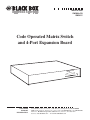
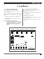
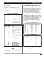
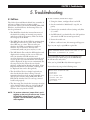
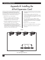
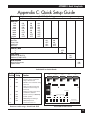
© Copyright 2000. Black Box Corporation. All rights reserved.
1000 Park Drive • Lawrence, PA 15055-1018 • 724-746-5500 • Fax 724-746-0746
MARCH 2000
SW540A-R3
SW541C
Code Operated Matrix Switch
and 4-Port Expansion Board
D
PERATE
CODE O SWITCH
MATRIX
STATUS
6 7 8
3 4 5
0 1 2
CUSTOMER
SUPPORT
INFORMATION
PWR
Order toll-free in the U.S. 24 hours, 7 A.M. Monday to midnight Friday: 877-877-BBOX
FREE technical support, 24 hours a day, 7 days a week: Call 724-746-5500 or fax 724-746-0746
Mail order: Black Box Corporation, 1000 Park Drive, Lawrence, PA 15055-1018
Web site: www.blackbox.com • E-mail: [email protected]
Code Operated Matrix Switch
FEDERAL COMMUNICATIONS COMMISSION
RADIO FREQUENCY INTERFERENCE STATEMENT
This equipment generates, uses, and can radiate radio frequency energy and if not installed
and used properly, that is, in strict accordance with the manufacturer’s instructions, may cause
interference to radio communication. It has been tested and found to comply with the limits for
a Class A computing device in accordance with the specifications in Subpart J of Part 15 of FCC
rules, which are designed to provide reasonable protection against such interference when
the equipment is operated in a commercial environment. Operation of this equipment in a
residential area is likely to cause interference, in which case the user at his own expense will
be required to take whatever measures may be necessary to correct the interference.
Caution:
Changes or modifications not expressly approved by the party responsible for
compliance could void the user’s authority to operate the equipment.
This digital apparatus does not exceed the Class A limits for radio noise emission from digital apparatus set out in
the Radio Interference Regulation of Industry Canada.
Le présent appareil numérique n’émet pas de bruits radioélectriques dépassant les limites applicables aux appareils
numériques de la classe A prescrites dans le Règlement sur le brouillage radioélectrique édicté par Industrie Canada.
TRADEMARKS
HP® is a registered trademark of Hewlett-Packard.
LaserJet™ is a registered trademark of Hewlett-Packard.
DEC® is a registered trademark of Compaq Corporation.
This product is CE certified. This certificate indicates that the product is suitable for use in commercial
and light industrial environments as defined in EN 50081-1:1992.
NOTE
Shielded interface cables must be used with this product. Call Technical Support at 724-746-5500
for guidance in choosing cables.
2
CONTENTS
Contents
Hardware Section
1. Specifications......................................................................................5
2. Introduction .......................................................................................6
3. Installation..........................................................................................7
3.1 Setting the Internal DIP Switches ..............................................7
3.2 Configuring the Shunt Jumpers for DTE or DCE ....................9
3.3 Connecting Devices to the Switch’s Parts ................................10
4. Operation .........................................................................................11
4.1 Front-Panel Indicators ..............................................................11
4.2 Reset Button ..............................................................................11
4.3 ASCII Control Codes ................................................................11
4.4 Break Detection ........................................................................14
5. Troubleshooting...............................................................................15
5.1 Self-Tests ....................................................................................15
5.2 Sample Test Program ................................................................16
Appendix A ASCII Codes ..................................................................17
Appendix B Installing the 4-Port Expansion Card...........................18
Appendix C Quick Setup Guide.........................................................19
LINKUP Software
1. Introduction .....................................................................................21
1.1 What Is LINKUP? ......................................................................21
12. Hardware Requirements...........................................................21
2. Setup and Configuration.................................................................23
2.1 Files on the LINKUP disk .........................................................23
2.2 Making a Backup Copy .............................................................23
2.3 Installing the LINKUP Files on Your Hard Drive....................24
2.4 Modifying your AUTEXEC.BAT File .......................................24
2.5 Default Settings .........................................................................25
2.6 Configuring the COMS, LINKUP, and DOS ...........................25
3. Running LINKUP ............................................................................27
3.1 Hints for Using LINKUP and the COMS ................................27
3.2 Sending Data with DOS ............................................................27
3.3 Sending Data with Your Application Programs.......................27
4. Troubleshooting...............................................................................29
3
Code Operated Matrix Switch
Hardware Section
D
PERATE
CODE O SWITCH
MATRIX
0 1 2
4
STATUS
6 7 8
3 4 5
PWR
CHAPTER 1: Specifications
1. Specifications
Leads Supported — 1-8, 20, 22
Connectors — Base Unit: (5) DB25S 25-pin sub-D female; Unit with 4-Port
Expansion Board: (9) DB25S 25-pin sub-D female
Indicators — 10 LEDs: (1) Power, (9) Port Activity showing Receive activity
Interface — Asynchronous RS-232C/V.24 DTE/DCE (each port individually
selectable)
Speeds — 110 to 19,200 bps (each port individually selectable)
Memory — 31K buffer
Enclosure — Steel
Operating Temperature — 32 to 113°F (0 to 45°C)
Storage Temperature — -4 to 158°F (-20 to 70°C)
Humidity — 0 to 95% relative, noncondensing
Mean Time Between Failures — 20,000 hours for standard Switch (Ground Benign
Environment), 16,000 hours for standard Switch with 4-Port Expansion Board
Power — 115-VAC, 60 Hz, at 175 mA (230-VAC, 50-Hz version available)
Size — 2.3"H x 11.2"W x 12.1"D (5.8 x 28.4 x 30.7 cm)
Weight — 9.6 lb. (4.3 kg) for standard Switch, 10.2 lb. (4.6 kg) for standard Switch
with 4-Port Expansion Board
The Code Operated Matrix Switch (COMS for short) is a versatile microprocessor-
5
Code Operated Matrix Switch
2. Introduction
controlled electronic switch. It allows any of its
ports to communicate with any other connected
port, or any pair of ports to communicate
simultaneously.
For example, a number of terminals or
computers can share several peripheral devices,
such as printers or modems. A simple code from
any terminal or computer links it to the desired
peripheral.
Here’s another application: one computer is
connected to a laser printer, while another
computer is simultaneously connected to a dotmatrix printer. Later, the printers could be swapped
(as in an X-switch configuration) without the need
to change or move any cables.
The standard Code Operated Matrix Switch has
five ports that support any combination of input,
output, or bidirectional devices. The Switch has 32K
of RAM with approximately 31K devoted to
buffering. The 4-Port Expansion Board
(Model SW541-C) provides four additional
input/output ports (see Appendix B for
instructions on setting it up).
6
This manual includes a quick-reference section,
Appendix C. If you’re familiar with the operation of
the COMS, use the charts in that section to set up
the Switch. If not, proceed through Sections 3, 4,
and 5.
NOTE: This manual will take you through installation, operation, and troubleshooting for the
Code Operated Matrix Switch in both the
five-port and nine-port versions. See
Appendix B for instructions on setting up
the 4-Port Expansion Board.
You’ll need an edged or pointed object small
enough to set DIP switches to install the Switch.
These are the steps to follow for installation:
1. Set the internal option DIP switches.
2. Configure shunt jumpers for DTE or DCE.
3. Connect devices to the switch ports.
4. Supply power to the Code Operated Matrix
Switch.
CHAPTER 3: Installation
3. Installation
3.1.1 INDIVIDUAL PORT CONFIGURATIONS
A number of options can be configured for each
port individually. You can select:
3.1 Setting the Internal DIP Switches
Remove the cover of the Switch’s enclosure to
expose the PC board.
• Baud rate: 110, 300, 600, 1200, 2400, 4800, 9600,
or 19,200 bps
• Parity: Even, odd, or none
• Data bits per word: 7 or 8
• Flow Control: Hardware (DTR/CTS) or software
(X-ON/X-OFF)
• Break detection: Break to disconnect or ignore
breaks
Figure 1 shows the location of the Code Operated
Matrix Switch’s internal DIP switches. There are two
types:
1. Individual Port Switches (see Section 3.1.1)
2. System Switches (these apply to all ports; see
Section 3.1.2)
NOTE: DIP Switches may have different
designators to indicate the “ON” and “OFF”
settings. In this manual, “ON” is equivalent
to “Closed” and “OFF” is equivalent to
“Open.”
(BACK)
PORT 4
PORT 3
PORT 2
PORT 1
PORT 0
DTE
DTE
DTE
DTE
DTE
DCE
DCE
DCE
DCE
DCE
W1
J7
R1
J1
U20
U23
RESET BUTTON
VR1
S1
INDIVIDUAL PORT SWITCHES
SYSTEM SWITCHES
(SWF & SWG)
SW
G
PORT 4
PORT 3
PORT 2
PORT 1
PORT 0
SW
E
SW
D
SW
C
SW
B
SW
A
SW
F
OFF
OFF
OFF
OFF
OFF
OFF
OFF
STATUS INDICATORS
CH0CH1CH2CH3CH4CH5CH6CH7CH8
PWR
(FRONT)
Fig. 1. Internal Switch Locations for the Standard Code Operated Matrix Switch
7
Code Operated Matrix Switch
On the standard 5-port model, the DIP switches that
correspond to each port are:
•
•
•
•
•
Port 0: SWA
Port 1: SWB
Port 2: SWC
Port 3: SWD
Port 4: SWE
3.1.2 SYSTEM CONFIGURATIONS
In the lower left corner of the printed circuit board
are two DIP switch banks, SWF and SWG, for
configuring the system. Switch SWG is reserved for
future use. Switch SWF uses the first four positions,
with Positions 5 through 8 reserved for future use.
The settings and functions of the first four positions
of SWF are given in Table 2. Check the chart, and
then use a pointed object, such as a small
screwdriver, to set the bank.
For the 4-Port Expansion Board:
•
•
•
•
Table 1 lists the individual options and settings for
each port switch.
Port 5: SWH
Port 6: SWI
Port 7: SWJ
Port 8: SWK
Table 1. Switch Port Options (Individual Port Switch Banks)
Option
1
2
3
Switch Position Settings
4
5
6
7
8
Baud Rate
110
300
600
1200
2400
4800
9600
19,200
ON
OFF
ON
OFF
ON
OFF
ON
OFF
ON
ON
OFF
OFF
ON
ON
OFF
OFF
ON
ON
ON
ON
OFF
OFF
OFF
OFF
Parity
No Parity
Even Parity
Odd Parity
No Parity
ON
OFF
ON
OFF
ON
ON
OFF
OFF
Data Bits/Word
7
8
OFF
ON
Flow Control
Hardware (DTR/CTS)
Software (X-ON/X-OFF)
ON
OFF
Break Detection
Break to Disconnect
Ignore Breaks
8
ON
OFF
CHAPTER 3: Installation
3.2 Configuring Shunt Jumpers for DTE or DCE
Lead Pass-Through
This function allows the COS II either to pass
hardware-handshake leads to connected devices or
to block them. If they are blocked, the leads will still
be used to regulate the internal buffer of the
Switch. The following table shows the behavior of
the COS II for different combinations of devices.
Table 2. Leads Passed Through.
Port 1
Port 2
Leads Passed
DTE
DTE
DTE
DCE
DCE
DTE
DCE
DCE
Port 1 DCD to Port 2 RTS
Port 2 DCD to Port 1 RTS
Port 1 DCD to Port 2 DCD
Port 2 RTS to Port 1 RTS
Port 1 RTS to Port 2 RTS
Port 2 RTS to Port 1 DCD
Port 1 RTS to Port 2 DCD
Port 2 RTS to Port 1 DCD
Table 3. Settings and Functions for Switch SWF
Switch
Position
1
Switch
Setting
ON
OFF
2
ON
OFF
3
4
5-8
ON
OFF
ON
OFF
Function
Reverts to attention string of
@ and switches to factory
defaults when reset or repowered.
Maintains user-set attention
upon reset.
Limits port name changes and
attention-character changes
to Port 0 only.
All ports can change port
names and attention
characters.
Perform self-test (see
Section 5)
Normal operation.
DCD (RTS) passed through.
DCD (RTS) blocked.
Reserved for future use.
NOTE
Each of the five (or nine) ports has a bank of shunt
jumpers located next to its port connector on the
rear of the internal board or boards. (See Fig. 1 for
their location.) These jumpers allow each port to be
configured as either Data Terminal Equipment
(DTE) or Data Communications Equipment
(DCE). You don’t need a crossover cable to connect
your equipment to the Code Operated Matrix
Switch—just standard straight-through cabling.
Shunt jumpers are fragile. When removing them,
use a small flathead screwdriver or IC remover. With
a screwdriver, use a gentle motion, prying from one
end of the shunt. When installing, press down
gently only after you have made sure all pins are
above holes.
Table 3. Input and Output Signals
Signal
Pin Direction as DTE Direction as DCE
TXD
RXD
RTS
CTS
DSR
DCD
DTR
RI
2
3
4
5
6
8
20
22
Output
Input
Output
Input
N/A
Input
Output
Input
Input
Output
Input
Output
Output
Output
Input
N/A
Table 4. DIP Shunt Settings
Connecting straight cable to:
PC w/25-pin connector
DEC™ computer
Data General computer
Most printers (ex: HP®
LaserJet®)
DTE devices
Modem
HP minicomputer
DCE devices
Set DIP Shunt to:
DCE
DCE
DCE
DCE
DCE
DTE
DTE
DTE
NOTE: If you use a cross-pinned cable, set the DIP
shunt setting to the opposite of the one
recommended above.
To use the saving function of the
SW540A-R3, DIP switch F position 1
must be OFF.
9
Code Operated Matrix Switch
3.3Connecting Devices to the Ports
After you configure the internal switches and
jumpers, connect the Code Operated Matrix Switch
to the input/output devices:
1. Replace the Switch’s cover.
2. Connect the input/output device cables to
Ports 0-4 (or 0-8 if you have the 4-Port
Expansion Board) of the COMS.
3. Plug the wall-mounted power supply into a
suitable outlet.
10
The Switch is now ready. Go on to Chapter 4 to
learn about the Switch’s controls and indicators.
You’ll control your switch mostly through ASCII
codes you send from the devices connected to it.
There are, however, mechanical controls and
indicators on the Code Operated Matrix Switch.
This chapter begins with the mechanical controls,
Sections 4.1 and 4.2, and then treats the character
codes in the sections that follow.
CHAPTER 4: Operation
4. Operation
4.1Front-Panel Indicators
4.3 ASCII Control Codes
There are a total of ten LEDs, located on the
Switch’s right front panel: nine port status LEDs
and one power LED.
The Code Operated Matrix Switch accepts commands from any port. (No one port is designated
as a master port.) A single command consists of the
attention string, followed by a command sequence
that may be from one to three characters long. The
Help screen, shown in Fig. 2., presents all the
command sequences for the Switch.
Power LED: This indicator lights when the power
is on.
Port Status LEDs: The nine status LEDs accommodate the 4-Port Expansion Board as well as the
standard 5-port Switch. A port’s LED flickers
momentarily, indicating activity, whenever that port
receives data. The LED will flash only if a link is established and actual data (not commands) is being
received.
4.2 Reset Button
Figure 1 shows the location of the reset button.
Use this button to reset the Code Operated Matrix
Switch. Any time you change the internal switch
settings, press the reset button to activate the
changes. While the Code Operated Matrix Switch
is resetting, it does not process data.
Disconnecting power from the Code Operated
Matrix Switch also resets it.
A third way to reset the switch is to use the
Remote Reset command. See RR in Section 4.3.2.
4.3.1 THE ATTENTION STRING
The ATTENTION string is a character string,
0 to 8 characters in length, that must precede all
commands. Enter the character string via the SET
ATTENTION command. The factory default is the
character @. To change the attention string, see the
A (Set Attention String) command in the next section.
4.3.2 THE COMMANDS
?—Help
When the Code Operated Matrix Switch receives an
ATTENTION string followed by a ? (question mark),
it sends the HELP screen out to the port that issued the
command. See Fig. 2 on the next page.
Q—Query
When the Code Operated Matrix Switch receives
an ATTENTION string followed by a Q, it sends
the STATUS screen out to the port that issued
the command. (See Fig. 3.)
11
Code Operated Matrix Switch
HELP SCREEN
COMMAND NAME
DESCRIPTION
Attention Character must precede all commands
L<x><y>
U<x><y>
<y>
DA
T<x><y>
B<x>
A<x><z>
CR)
N<x><z>
Q
S
RL
RR
?
<BREAK>
LINK
UNLINK
Make regular link from port <x> to port <y>
Remove regular or transparent link port <x> to port
DISCONNECT ALL
TRANSPARENT LINK
SEND BREAK
SET ATTENTION
Disconnects all regular and transparent links
Make transparent link from port <x> to port <y>
Send break out port <x>
Set port <x> attention to <z> (up to 8 characters,
SET PORT NAME
QUERY
SAVE
RELOAD
REMOTE RESET
HELP
BREAK CONDITION
Set port <x> name to <z> (up to 8 chars, CR)
Query box for status
Save Connection Matrix
Reload factory default settings
Return unit to power up configuration
Displays help screen
Remove a regular or transparent link
Fig. 2. The Help Screen
The STATUS screen shows PORT NAMES, which
ports are LINKED to other ports, which links are
TRANSPARENT, (a transparent link does not honor
the Attention command), ACTIVITY (the presence
of buffered characters), and the ATTENTION
strings for each port.
L — Link
When the Code Operated Matrix Switch receives an
ATTENTION string followed by an L and two PORT
NUMBERS, it attempts to set up a bi-directional link
between these two ports. If either of these ports is
already linked, the Code Operated Matrix Switch
sends a message to the port that issued the
command, indicating that the link was not made.
Otherwise, the two ports link and the Code Operated
Matrix Switch sends a message to the port that issued
the command, indicating that it made the link.
Port
0
1
2
3
4
5
6
7
8
Name
Linked To
.......
.......
.......
.......
.......
.......
.......
.......
.......
NOTE: Any port can issue the Link command, even
if that port is not one of the two ports being
linked. For example, Port 1 could issue a
command to link Port 2 and Port 5.
U — Unlink
When the Code Operated Matrix Switch receives an
ATTENTlON string followed by a U and two PORT
NUMBERS, it attempts to break a bi-directional link
between these two ports (“unlink”). If these two
ports are not linked to each other, the Code
Operated Matrix Switch sends a message to the port
that issued the command, indicating that the unlink
was not made. Otherwise, the two ports will be
unlinked and the Code Operated Matrix Switch
sends a message to the port that issued the
command, indicating that the unlink was successful.
Transparent
N
N
N
N
N
N
N
N
N
Fig. 3. The Status Screen
12
Activity
N
N
N
N
N
N
N
N
N
Attention String
@
@
@
@
@
@
@
@
@
CHAPTER 4: Operation
NOTE: Any port can issue the Unlink command,
even if that port is not one of the two ports
that will be unlinked. For example, Port 5
could command Port 2 and Port 3 to unlink.
NOTE: Any port can issue the Send Break
command. For example, Port 3 could issue a
command to send a break out Port 4.
A — Set Attention
DA — Disconnect All
When the Code Operated Matrix Switch receives an
ATTENTION string followed by DA, it will break
every link currently defined. The buffers are
purged, and any data in them is lost.
T — Transparent Link
A TRANSPARENT LINK is similar to a REGULAR
LINK, with only this exception: When a port is
transparently linked, the Switch will no longer
honor an ATTENTION string from that port. The
ATTENTION string is treated as data, to allow all
data to pass between two ports. If you want to break
a Transparent Link, you must enable break
detection (see Section 4.4), then send a break to
the switch from either of the devices attached to the
transparently linked ports (see B—Send Break). You
can also send the U—Unlink command from one of
the unattached ports.
When the Code Operated Matrix Switch receives
an ATTENTION string followed by a T and two
PORT NUMBERS, it attempts to set up a bidirectional TRANSPARENT link between these two
ports. If either of these ports is already linked, the
Code Operated Matrix Switch sends a message to
the port that issued the command, indicating that
the link was not made. Otherwise, the two ports link
and the Code Operated Matrix Switch sends a
message to the port that issued the command
indicating that the link was successful.
NOTE: Any port can issue the Transparent Link
command, even if that port is not one of the
two ports being transparently linked. For
example, Port 1 could issue a command to
transparently link Port 2 to Port 5.
B — Send Break
The Switch uses a break condition to unlink a pair
of ports. When it receives an ATTENTION string
followed by a B and a PORT NUMBER, it sends a
250-millisecond break condition out the indicated
port. Then it sends a message to the port that issued
the command, indicating that the break was sent.
When the Code Operated Matrix Switch receives an
ATTENTION string followed by an A and a Port
number, it echoes the A and the port number to
the indicated port. The Code Operated Matrix
Switch then waits for a 0- to 8-character
ATTENTION string followed by Return. If control
characters are entered, they will appear on the
screen as ^<letter>, where <letter> is the key you
pressed while holding down the control key. If a
zero-length ATTENTION string is entered for a
port, you will no longer be able to send commands
from that port.
NOTE: Any port can issue the Set Attention
command. For example, Port 5 could issue a
command to set the attention string for
Port 6. If you need more security, you can
designate Port 0 as the only port capable of
changing an attention string, by setting
Switch F’s Position 2 to ON.
N — Set Port Name
When the Code Operated Matrix Switch receives an
ATTENTION string followed by an N and a PORT
NUMBER, it echoes the N and the PORT NUMBER
to the indicated port. The Code Operated Matrix
Switch then waits for a 1 to 8 character PORT
NAME followed by Return.
NOTE: Any port can issue the Set Port Name
command. For example, Port 7 could issue a
command to set the port name for Port 8.
You can designate Port 0 as the only port
capable of changing a Port Name, by setting
Switch F’s Position 2 to ON.
S — Save
When the Code Operated Matrix Switch receives an
ATTENTION string followed by an S, it will save the
current connection matrix in nonvolatile memory.
This will preserve any combination of regular and
transparent links. After this Save operation is
completed, the links you saved will be restored any
time the Switch is reset.
13
Code Operated Matrix Switch
RL — Reload
4.4 Break Detection
When the Code Operated Matrix Switch receives an
ATTENTION string followed by RL, it returns to its
factory-default settings. All port names are replaced
with spaces, and all attention strings revert to the
default @. Any data that may be in the buffers is
purged.
When the Code Operated Matrix Switch detects an
incoming break condition, it will either act on it or
ignore it, depending on how DIP Switch Position 8
is set on each port. If Position 8 is ON, then when
any port on the Code Operated Matrix Switch is
linked to another port and receives a break
condition, the two ports will be unlinked. The Code
Operated Matrix Switch sends a message to the port
that requested the break condition, to indicate that
the unlink was successful. Otherwise, the Code
Operated Matrix Switch sends a message to the
requesting port to indicate that the unlink was
unsuccessful, since that port was not linked initially.
RR — Remote Reset
When the Code Operated Matrix Switch receives an
ATTENTION string followed by RR, it resets itself,
as though you had pushed the reset button or
turned the power off and back on. Any links you’ve
saved with the Save command will be restored.
Sometimes cable noise can be perceived as a
break, so unless you want a break to be a port’s
normal method of disconnection, you should
configure that port to ignore breaks. Set DIP
Switch Position 8 to ON.
14
CHAPTER 5: Troubleshooting
5. Troubleshooting
5.1 Self-Tests
The Code Operated Matrix Switch has a number of
self-tests to ensure that its circuitry is fully
operational. These tests check the RAM, LEDs, DIP
Switches, and Serial Ports. An Interrupt Test can
also be performed.
• The RAM Test checks the internal memory of
the Switch by writing an internal test pattern,
and then reads it for accuracy. This test checks
the integrity of the RAM.
• The LED Test checks the LEDs by turning them
all OFF, then ON one at a time, then all ON,
then OFF one at a time. This test tells you
whether the LEDs are working normally or
whether any are shorted. The test runs
continuously until you press any key to exit.
• The DIP Switch Test reads the DIP switches and
displays their settings on the screen. This test
tells you whether the DIP switches and
associated circuitry are operating normally and
are set up the way you want them. The settings
will be displayed on the screen continuously until you press any key. Then the test checks
whether an Expansion Board is installed. (If an
Expansion Board is not installed, readings will
be displayed but can be disregarded.)
• The Serial Port Test is a simple loopback test
that checks whether data is being correctly
transmitted and received on any particular port.
This test also checks, using DTR/CTS/RI or
RTS/DCD, whether the box can loop control
leads back properly.
To run a self-test, follow these steps:
1. Using the shunt, configure Port 0 as DCE.
2. Set the terminal to 9600 baud, 1 stop bit, no
parity.
3. Connect the terminal to Port 0, using only Pins
2, 3, and 7.
4. Set DIP Switch 3 on Switch F to the ON position
(the switch is OFF for normal operation).
5. Power the switch on.
6. When a self-test is run, this message will appear:
Type in your reply: capital R or capital O.
**CODE OPERATED MATRIX SWITCH SELF TEST V 1.0**
RUN TESTS (R)EPEATEDLY OR (O)NCE?
If you select R, the tests you select from the next
menu will repeat until you press the BREAK key.
O will run tests only once.
After you’ve picked R or O, this menu appears:
If you select A, you get the following tests:
WHICH TESTS SHOULD BE RUN?
(R)AM TEST
(L)ED TEST
(D)IP SWITCH TEST
(S)ERIAL PORT TEST
(I)NTERRUPT TEST
(A)LL TESTS
• The Interrupt Test checks the interrupt circuitry
of the Switch. During this test, the letter A will
appear on the screen. A message will indicate
whether the test passed or failed.
NOTE: To perform a data test, jumper Pins 2 and 3
together on the port you want to test. To test
DTR/CTS/RI, jumper Pins 20, 5, and 22
together. To test RTS/DCD, jumper Pins 4
and 8 together.
15
Code Operated Matrix Switch
SERIAL PORT TEST (EXPANSION BOARD IS
INSTALLED)
RAM TEST 64K RAM IS GOOD
LED TEST IN PROGRESS, ALL LEDS SHOULD TURN ON
AND OFF. PRESS ANY KEY TO EXIT
DIP SWITCH TEST (MAIN BOARD) HIT ANY KEY TO GO
TO NEXT TEST
SWITCHES ARE DISPLAYED IN BINARY (0 = OFF, 1 =
ON)
SWG
SWF
SWE
SWD
00000010
00100000
10000101 10000100 10000100
SWC
SWB
SWA
1000010110000101
SWJ
11101101
SWI
11110101
PORT
PORT
PORT
PORT
PORT
PORT
PORT
PORT
PORT
0
1
2
3
4
5
6
7
8
DATA
DTR/CTS/RI
RTS/DCD
FAILED
FAILED
FAILED
FAILED
FAILED
FAILED
FAILED
FAILED
FAILED
FAILED
FAILED
FAILED
FAILED
FAILED
FAILED
FAILED
FAILED
FAILED
*
FAILED
FAILED
FAILED
FAILED
FAILED
FAILED
FAILED
FAILED
SERIAL PORT TEST FAILED
EXPANSION BOARD IS INSTALLED
DIP SWITCH TEST (EXPANSION BOARD) HIT ANY KEY
TO
GO TO NEXT TEST
SWITCHES ARE DISPLAYED IN BINARY (0 = OFF, 1 =
ON)
SWK
11111101
PORT#
SWH
11100101
INTERRUPT TEST IN PROGRESS
A
INTERRUPT TEST PASSED
The tests are performed at 9600 bps, no parity, and
1 stop bit. The serial-port test will return a “*” for
every section that passes the test, and a “FAILED”
message otherwise. To perform a proper serial-port
test, you must tie together Pins 2 and 3 for the data
portion, Pins 20, 5, and 22 for the DTR/CTS/RI
portion, and Pins 4 and 8 for the RTS/DCD portion
for each port you wish to test.
5.2 Sample Test Program
Here is a sample test program written in BASIC for the Code Operated Matrix Switch. When run, this
program will output a test message on each port. To run this program, connect the PC to Port 0. REM
statements (“Remarks”) are optional, and the attention character is the default @.
100REM**CODE OPERATED MATRIX SWITCH TEST**
110OPEN "COM1:9600,N,8,1,CS,DS"AS1
120P=49
130PRINT #1,CHR$(64);
140PRINT #1,"L0";
150PRINT #1,CHR$(P)
160T=P-48
170PRINT #1,"THIS IS A TEST OF PORT #"T
180FOR I=1 TO 250
190NEXT I
200PRINT #1,CHR$(64);
210PRINT #1,"U0";
220PRINT #1,CHR$(P)
230P=P+1
240FOR I=1 TO 250
250NEXT I
260IF P=57 THEN GOTO 120 ELSE GOTO 130
16
:REM**
:REM**
:REM**
:REM**
:REM**
:REM**
:REM**
:REM**
:REM**
:REM**
:REM**
:REM**
:REM**
:REM**
:REM**
:REM**
SET UP COM 1 PC PORT**
SET PORT # TO 1 (DECIMAL 49)**
SEND ATTENTION CHAR (@) **
SEND LINK COMMAND**
SEND PORT # OUT COM 1**
CONVERT DEC. TO ACTUAL PORT #**
SENDS MESSAGE OUT COM 1**
DELAY**
LOOP**
SEND ATTENTION CHAR (@)**
SEND UNLINK COMMAND**
SEND PORT # OUT COM 1**
INCREMENT PORT #**
DELAY**
LOOP**
LOOPBACK FOR NEXT PORT**
APPENDIX A: ASCII Codes
Appendix A: ASCII Codes
CONTROL CHARACTERS
NUMBERS AND SYMBOLS
OCTAL HEX DECIMAL
0
0
0
NUL
1
1
1
SOH
2
2
2
STX
3
3
3
ETX
4
4
4
EOT
5
5
5
ENQ
6
6
6
ACK
7
7
7
BEL
10
8
8
BS
11
9
9
HT
12
A
10
LF
13
B
11
VT
14
C
12
FF
15
D
13
CR
16
E
14
SO
17
F
15
SI
20 10
16
DLE
21 11
17
DC1
22 12
18
DC2
23 13
19
DC3
24 14
20
DC4
25 15
21
NAK
26 16
22
SYN
27 17
23
ETB
30 18
24
CAN
31 19
25
EM
32 1A
26
SUB
33 1B
27
ESC
34 1C
28
FS
35 1D
29
GS
36 1E
30
RS
37 1F
31
US
OCTAL
40
41
42
43
44
45
46
47
50
51
52
53
54
55
56
57
60
61
62
63
64
65
66
67
70
71
72
73
74
75
76
77
HEX
20
21
22
23
24
25
26
27
28
29
2A
2B
2C
2D
2E
2F
30
31
32
33
34
35
36
37
38
39
3A
3B
3C
3D
3E
3F
DECIMAL
32
33
34
35
36
37
38
39
40
41
42
43
44
45
46
47
48
49
50
51
52
53
54
55
56
57
58
59
60
61
62
63
SP
!
"
#
$
%
&
'
(
)
*
+
,
.
/
0
1
2
3
4
5
6
7
8
9
:
;
<
=
>
?
LOWER CASE
UPPER CASE
OCTAL
100
101
102
103
104
105
106
107
110
111
112
113
114
115
116
117
120
121
122
123
124
125
126
127
130
131
132
133
134
135
136
137
HEX DECIMAL
40
64
41
65
42
66
43
67
44
68
45
69
46
70
47
71
48
72
49
73
4A
74
4B
75
4C
76
4D
77
4E
78
4F
79
50
80
51
81
52
82
53
83
54
84
55
85
56
86
57
87
58
88
59
89
5A
90
5B
91
5C
92
5D
93
5E
94
5F
95
@
A
B
C
D
E
F
G
H
I
J
K
L
M
N
O
P
Q
R
S
T
U
V
W
X
Y
Z
[
\
]
^
-
OCTAL
140
141
142
143
144
145
146
147
150
151
152
153
154
155
156
157
160
161
162
163
164
165
166
167
170
171
172
173
174
175
176
177
HEX DECIMAL
60
96
61
97
62
98
63
99
64 100
65 101
66 102
67 103
68 104
69 105
6A 106
6B 107
6C 108
6D 109
6E 110
6F 111
70 112
71 113
72 114
73 115
74 116
75 117
76 118
77 119
78 120
79 121
7A 122
7B 123
7C 124
7D 125
7E 126
7F 127
`
a
b
c
d
e
f
g
h
i
j
k
l
m
n
o
p
q
r
s
t
u
v
w
x
y
z
{
|
}
~
del
17
Code Operated Matrix Switch
Appendix B: Installing the
4-Port Expansion Card
Before you begin, follow standard procedures for
grounding any accumulated static electricity, to
prevent damage to the circuits of the main and
expansion boards. Also, shut off the Switch’s power
by unplugging the wall-mounted transformer.
5. Screw the 8 screwlocks into the holes along the
row of expansion ports. Also set screws into the
standoffs.
6. Set the baud rate, parity, word size, flow
control, and break-detection capacity with DIP
Switch Banks SWH through SWK. Use the chart
on the next page.
1. Remove the cover of the Switch.
2. Make sure you have set Ports 0 through 5
properly for DTE or DCE operation. Refer
to Section 3.2 of the manual for details.
7. Set each expansion port for DTE or DCE
operation with the DIP shunts. For precautions
and more information on shunts, see Section
3.2 (page 8).
3. Install the standoffs in the two holes that run
along the midline of the main board.
8. Replace the cover of the Switch.
4. Insert the Expansion Board’s row of RS-232
connectors into the row of holes at the rear of the
Switch. Make sure the connector that projects
from the bottom of the Expansion Board is seated
firmly in the socket of the main board.
9. Connect your additional devices to the Switch.
10. Plug the wall-mounted transformer into its
AC socket.
(BACK)
PORT 8
PORT 7
PORT 6
PORT 5
DTE
DTE
DTE
DTE
DCE
DCE
DCE
DCE
INDIVIDUAL PORT SWITCHES
(PORTS 5 THRU 8)
PORT 8
OFF
PORT 7
OFF
SWK
OFF
SWJ
(FRONT)
The 4-Port Expansion Board
18
PORT 6
PORT 5
OFF
SWI
SWH
APPENDIX C: Quick Setup Guide
Appendix C: Quick Setup Guide
Option
1
2
3
Switch Position Settings
4
5
6
7
8
Baud Rate
110
300
600
1200
2400
4800
9600
19,200
ON
OFF
ON
OFF
ON
OFF
ON
OFF
ON
ON
OFF
OFF
ON
ON
OFF
OFF
ON
ON
ON
ON
OFF
OFF
OFF
OFF
Parity
No Parity
Even Parity
Odd Parity
No Parity
ON
OFF
ON
OFF
ON
ON
OFF
OFF
Data Bits/Word
7
8
OFF
ON
Flow Control
Hardware (DTR/CTS)
Software (X-ON/X-OFF)
ON
OFF
Break Detection
Break to Disconnect
Ignore Breaks
ON
OFF
Individual Port Switch Banks
Switch
Position
1
Switch
Setting
ON
OFF
(BACK)
Function
PORT 4
Reverts to factory-set attention
string of @ when reset
Maintains user-set attention string
when reset
PORT 3
PORT 2
PORT 1
PORT 0
DTE
DTE
DTE
DTE
DTE
DCE
DCE
DCE
DCE
DCE
W1
J7
R1
J1
U20
U23
2
3
OFF
All ports can change port names
and attention characters
DCD (RTS) passed through
OFF
DCD (RTS) blocked
PORT 4
PORT 3
PORT 2
PORT 1
PORT 0
SW
E
SW
D
SW
C
SW
B
SW
A
SW
F
OFF
ON
SW
G
OFF
Normal operation
OFF
OFF
S1
INDIVIDUAL PORT SWITCHES
SYSTEM SWITCHES
(SWF & SWG)
OFF
Perform self-test (see Section 5)
OFF
ON
RESET BUTTON
VR1
OFF
5-8
Limits port name changes and
attention-character changes to
Port 0 only
OFF
4
ON
STATUS INDICATORS
CH0CH1CH2CH3CH4CH5CH6CH7CH8
PWR
Reserved for future use
(FRONT)
Functions and Settings, Switch Bank SWF
Internal Board Locations
19
LINKUP Software
for the Code Operated Matrix Switch
LINKUP
PC SUPPORT PROGRAM
Version 2.0
©Copyright 1992. Black Box Corporation. All rights reserved.
Introduction
1. Introduction
1.1What Is LINKUP?
LINKUP is a support program included with the
Code Operated Matrix Switch (COMS). It works
with either the older versions of the COMS (SW540
and SW540A-R2) or the current version (SW540AR3).
You don’t need LINKUP to operate the COMS.
However, it can be very useful when you need to
execute a COMS command (for example, to make
or break a link between two COMS ports). It’s
especially useful when you don’t have a terminalemulation program to perform these functions.
LINKUP is a user-friendly, menu-driven program
with a quick-help window and an on-line user’s
manual for the COMS. The program lets you
execute every COMS command, run diagnostic
tests, or enter a dumb-terminal emulation program
(so you can communicate directly with the COMS if
you wish).
With LINKUP, you can check to see whether a
shared device is in use by someone else. If it’s free,
LINKUP will help you create a link from your
computer to the device. Once you are linked
through the COMS, you can exit from LINKUP.
Your regular application programs can now use the
shared device as if it were connected directly to
your computer—for example, you can print to a
shared printer from your word-processing program.
Figure 1 shows how the menus in LINKUP are
arranged.
1.2Hardware Requirements
LINKUP runs on the IBM® PC family of computers,
including the PC/XT™ and AT®, and on any true
IBM compatible with a disk drive capable of reading
a 360K diskette. Since it’s a text-based program, it
runs on any 80-column monitor.
21
Code Operated Matrix Switch
MAIN MENU
Links (view/make/break)
Terminal Emulation Mode
Display User’s Manual
Other Options Menu
OTHER OPTIONS MENU
Diagnostic Tests
COM Port Settings
Special Commands
LINK MENU
View Current Links
Make Regular Link
Make Transparent Link
Unlink Linked Ports
Break Your Trans./Reg. Link
DIAGNOSTIC TEST MENU
Test PC’s 232 Outputs
Loop Back Test
Test SW540’s 232 Outputs
Test SW540 Baud Rate
COM PORT SETTINGS MENU
SPECIAL COMMANDS MENU
View/Set Attention Strings
Set Port Name
Send Break to COMS
Send Break out COMS Port
Save Links in NVR
Disconnect All Lines
Reload Factory Defaults
Restore Saved Links/Reset
Display Software Version
22
Set COM Port
Set Baud Rate
Set Word Structure
Setup and Configuration
2. Setup and Configuration
2.1 Files on the LINKUP Disk
There are five files on your LINKUP disk:
1. LINKUP.EXE: The executable version of the
program.
2. LINKUP.CFG: A data file that keeps your
current configuration of the program (baud
rate, data bits, and so on).
2.2.1 MAKING A BACKUP WITH DISKCOPY
1. Format a blank 360K diskette, to match the
format of the LINKUP diskette).
2. Place the LINKUP diskette in Drive A.
3. To make a backup copy, type:
A:
(makes Drive A: the current working directory)
3. LINKUP.DOC: The on-line user’s manual for
the COMS.
diskcopy
4. README.BBC: The LINKUP user’s manual
(this manual you’re reading).
When DOS prompts you to “enter target disk,”
place your new blank disk in Drive A.
5. INSTALL.BAT: The automatic installation
program to install LINKUP on your hard drive.
2.2 Making a Backup Copy
We encourage you to share this program with all
other users of the Code Operated Matrix Switch,
and to make a backup copy for your protection. You
may copy the disk freely, as long as:
• You make no changes to any file on this diskette.
• Each copy you make includes all files on the
original diskette.
• You include the following copyright notice on
all copies.
“Copyright © 1992. Black Box Corporation. All
rights reserved.”
2.2.2
MAKING A BACKUP WITH COPY
NOTE: You must have two disk drives to make a
backup with COPY.
1. Format a blank diskette and place it in Drive B.
2. Place the LINKUP diskette in drive A.
3. To make a backup copy, type:
A:\
(makes Drive A the current working directory)
copy *.* B:
(copies all files from the LINKUP disk to the
blank disk in Drive B)
DOS gives you two ways to make a backup copy. If
you have only one disk drive, use the DISKCOPY
command. If you have two disk drives, you’ll
probably find it more convenient to use COPY. (If
your disk drive can’t format a blank disk to match
the format of the LINKUP disk, you’ll have to use
the COPY command.) See your DOS manual for
help with any of the DOS commands used below.
23
Code Operated Matrix Switch
2.3 Installing the LINKUP Files
on Your Hard Drive
The batch program INSTALL.BAT will
automatically install the LINKUP files on your hard
drive. If you prefer to do the installation yourself,
skip to the next section.
2.3.1
INSTALLING THE LINKUP FILES
AUTOMATICALLY
1. Place your backup copy of the LINKUP disk in
Drive A.
2. Type the following DOS commands at the
command prompt:
A:\
(makes Drive A the current working directory)
INSTALL
(executes the INSTALL program)
3. The program will tell you what to do from here.
2.3.2 INSTALLING THE LINKUP FILES YOURSELF
1. If you’ve been using a previous version of
LINKUP, make sure you delete all the old
LINKUP files from your hard drive. They would
probably be in a directory called “LINKUP.”
2. Place your backup copy of the LINKUP disk in
Drive A.
3. Type the following DOS commands at the
command prompt:
2.4 Modifying Your AUTOEXEC.BAT File
You might need to use a number of DOS commands
to set up your system for LINKUP. If you add them
to your AUTOEXEC.BAT file, they’ll run
automatically when you turn your machine on, and
you won’t have to type them in again every time you
run LINKUP. Reboot your PC after modifying your
AUTOEXEC.BAT file.
If you don’t know how to create or edit the
AUTOEXEC.BAT file, See your DOS manual’s
sections on the AUTOEXEC.BAT file and the DOS
editor program EDLIN.
2.4.1 DOS PATH AND APPEND COMMANDS
You might want to add these lines to your
AUTOEXEC.BAT file so you can access LINKUP
files from any directory or drive on your machine.
Otherwise, you can access LINKUP only if you make
your working directory the directory LINKUP was
installed in.
path = c:\linkup
(allows DOS to find the .exe file in this
directory)
append = c:\linkup
(allows DOS to find the data files in this
directory)
NOTE: The path “c:\linkup” is for example only.
Use the directory name you selected when
you installed LINKUP (see Section 2.3).
c:\
md linkup
If the “append.com” file is not in directory “c:\”
then your path statement must first include the
directory of this file. Separate directories with a
semicolon.
(makes a new directory called “linkup”—or
whatever name you prefer—unless a directory
by that name already exists)
If a path or append statement already exists in your
AUTOEXEC.BAT file, just add the following to the
end of that existing statement:
(makes Drive C the current working directory)
copy a:*.* c:\linkup
(copies files from Drive A: to the directory on
the hard drive)
24
;c:\linkup
Setup and Configuration
2.4.2 DOS MODE COMMAND
The MODE command can be used to configure
communications (COM) port parameters and to
redirect parallel printer output to a COM port.
DOS MODE COM Command. You’ll need to add a
MODE COM command to your AUTOEXEC.BAT
file if:
• You will be using the DOS print command to
send data to the COMS.
• You will be using an application that does not
allow you to set the baud rate and word
structure of your COM port.
If you meet either of those conditions, add the
following command to your AUTOEXEC.BAT file:
2.5 Default Settings
The COMS hardware and LINKUP support
program should be shipped from the factory with
the following default configuration:
Code Operated Matrix Switch:
• 19,200 baud, 7 data, no parity, X-ON/X-OFF
flow control (all ports)
• attention string “@” (all ports)
• <break> sequences are ignored (for example, a
port’s link will not be broken on <break>)
• a user-set attention string remains if the COMS
is reset
MODE COM1:9600,N,8,1
• all ports can change port names and attention
strings
(specifies asynchronous communications
parameters as 9600 baud, no parity, 8 data bits,
1 stop bit)
• the COMS is in Normal Operation (not running
its internal self-test)
DOS MODE LPT Command. You’ll need to add a
MODE LPT command to your AUTOEXEC.BAT
file if:
• You will be using the DOS print command to
send data to the COMS and you do not want to
enter “COM1” or “COM2” at the PRINTcommand prompt (“list device [PRN]: ”).
• You will be using an application program that
does not allow you to select a COM port as your
print/list device.
If you meet either of those conditions, add the
following command to your AUTOEXEC.BAT file:
MODE LPT1:=COM1
(redirects printer output from Parallel Printer
Port 1 to Communications Port 1)
NOTE: You must use the MODE COM command to
specify the asynchronous communications
mode before you can redirect parallel printer
output to the COM port with the MOD LPT
command. See your DOS manual for more
information on the MODE command.
• DCD and RTS are not passed through between
linked ports
LINKUP Program:
• 19,200 baud, 7 data, no parity, flow control N/A
• attention string “@”
• COM Port #1
DOS COM Port:
Use the DOS MODE COM command in your
AUTOEXEC.BAT file to set your computer’s
defaults for baud rate and word structure for any
communication (COM) port.
2.6 Configuring the COMS, LINKUP, and DOS
The Code Operated Matrix Switch (COMS),
LINKUP Support Program, and DOS must all be
initially configured to use the same:
• PC COM port (for example, COM1)
• baud rate (for example, 9600)
• word structure:
• data bits (for example, 8)
25
Code Operated Matrix Switch
• parity (for example, none)
• stop bits (for example, 1)
Configure the COMS with internal DIP switches
and shunt jumpers (see the hardware section in the
front of this manual for more detail).
To configure LINKUP, install the program. Then
use the built-in menu commands to configure the
support software (see Fig. 1, “Menus in the Linkup
Software,” for more details).
For DOS, use the MODE COM command to
configure COM port parameters (see Section 2.4.2,
“DOS MODE Command,” for more details).
26
Running LINKUP
3. Running LINKUP
To run the program, just type “LINKUP” at the DOS
command prompt.
3.2 Sending Data with DOS
NOTE: If you haven’t told DOS where the LINKUP
files are (via the path and append
statements in your AUTOEXEC.BAT file),
first make the directory that holds the
LINKUP files your working directory.
You can use the DOS PRINT command to send data
through the COMS unit. The PRINT command will
let you send a file out your PC’s COM port using the
baud rate and word structure defined by the last
MODE COM command (see Section 2.4.2, “DOS
MODE Command”). The PRINT command configures the COM port for hardware flow control.
3.1 Hints for Using LINKUP and the Code
Operated Matrix Switch
When you’re using the COMS and LINKUP, it helps
to keep these recommendations in mind:
• Give each port on the COMS a unique,
descriptive name.
• Select the default attention string (“@”) on all
COMS ports and LINKUP programs. It’ll be
easier to keep track of.
• Before making a link, check to make sure the
desired port is not already in use
• Before breaking someone else’s link, make sure
that user has finished.
• When you can, make a Transparent Link instead
of a Regular Link. Making a Transparent Link
will often eliminate problems related to the
content of the data.
• After your link is made, exit LINKUP and use
your regular application program or the DOS
PRINT command to send or receive data
through the COMS unit.
• After all your data has passed through the
COMS unit, reenter LINKUP and break your
Transparent Link with the BREAK YOUR LINK
menu option in the Link Menu.
Example:
PRINT <filename.ext>
NOTE: We do not recommend using the DOS COPY
command (for example, “COPY filename.ext
COM1”) because it does not support flow
control.
If you used a MODE LPT command to redirect
parallel-printer output to a COM port, then just use
the default (“PRN”) value at the next DOS prompt
for list device. Otherwise, enter “COM1” as the list
device the first time you execute the print
command.
3.3 Sending Data with Your Application
Programs
You can also send data through the COMS unit with
commands in your application programs.
For some applications, like communications
packages, you can configure the COM port parameters (including flow control) and use a
transmit/send or receive/ capture command to
transfer data through the COM port. These
programs usually have options to use standard
protocols (like the XMODEM protocol) to transfer
files between two PCs’ COM ports.
27
Code Operated Matrix Switch
Most other application programs are designed to
send data to an attached parallel printer. With these
programs, you need to redirect the parallel printer
output to a communications (COM) port and
configure the COM ports parameters. There are
two ways to redirect the output:
1. Many programs will prompt you for a print/list
device. If yours does, you may be able to enter
“COM1” or “COM2” and have the program
itself redirect the print data out the
communications port.
28
2. You can redirect parallel printer output out the
COM port of your choice with the DOS MODE
LPT command (see Section 2.4.2, “DOS Mode
Command”). Then, when your application tries
to send data to the printer port, DOS will
redirect the data to the COM port.
In most cases, application programs like these will
use the communications parameters for baud rate
and word structure set up in the last DOS MODE
COM command. (See Section 2.4.2.) Most of these
programs will also use hardware flow control.
Troubleshooting
4. Troubleshooting
Diagnostic tests are available as menu options in the
LINKUP program to assist you in testing your COM
port, your cable connecting to the COMS, and the
COMS port, and to determine the baud rate (but
not the parity setting) of the COMS port.
Make sure the COMS unit’s BREAK DETECTION
option is set to “Break to Disconnect” for your port.
See the COMS user’s manual to find out which
Switch Bank is assigned to your port, then make
sure position 8 is ON.
You can diagnose and solve many software problems
yourself. For information on hardware problems,
refer to the troubleshooting section in the COMS
user’s manual.
PROBLEM: The SAVE LINKS IN NVR menu option in
LINKUP isn’t working.
PROBLEM: None of the LINKUP commands that
communicate with the COMS unit are working.
Make sure that your computer is cabled correctly to
the COMS unit.
Make sure that both the COMS unit and the
LINKUP program are configured for the same baud
rate and word structure.
Check out the attention strings:
• Make sure the COMS port’s attention string
matches the attention string used by the
LINKUP support program.
• You might try having a user at another station
change your COMS port’s attention string to the
default of “@” with the “View/Set Attention
Strings” command.
• Or you can set Switch Bank SWF Position 1 on
the COMS to “ON” (so that all attention strings
will default to “@” when the COMS is reset) and
reset the unit. After this, your COMS port
should be using the attention string “@.”
• Now change your LINKUP program’s attention
string to “@” with the “View/Set Attention
Strings” command (make sure you change only
the LINKUP program’s attention string).
• If you want users to be able to save their
attention-string changes, remember to turn SWF
Position 1 to “OFF” and reset the COMS again.
COMS units with product codes earlier than SW540R2 don’t have this feature, so they simply ignore this
command.
PROBLEM: These commands aren’t working:
• DISCONNECT ALL LINES
• RELOAD FACTORY DEFAULTS
• RESTORE SAVED LINKS/RESET
COMS units with product codes earlier than
SW540A-R3 don’t have these features, so they
simply ignore these commands.
PROBLEM: The SET NAME and SET ATTENTION
menu options in LINKUP aren’t working.
If your COMS is configured to allow only the user
attached to Port 0 to change names, no other users
will be able to use these commands. (Switch Bank
SWF Position 2 should be OFF to allow any port to
change port names and attention strings)
PROBLEM: I successfully made the link to my printer
with LINKUP, but when I send my file it is not received
correctly or it is not received at all.
Make sure the DOS MODE COM command in your
AUTOEXEC.BAT file is configuring the correct
COM port for the same baud rate and word
structure that the COMS unit is using. Also check
whether you need to configure the COMS unit,
LINKUP, and DOS to use 8-bit data (for graphics
data).
PROBLEM: Just a few of the LINKUP commands don’t
work correctly (like the “Break Your Trans./Reg. Link”
command).
29
Code Operated Matrix Switch
PROBLEM: I’m still having problems.
If you still need help, check these sources:
• Your COMS user’s manual for information on
hardware problems.
• LINKUP’s on-line help information.
• Your DOS manual for help on any of the DOS
commands, and also on EDLIN (the editing program you can use to create or change your
AUTOEXEC.BAT file).
NOTE: You have to configure the COMS, LINKUP,
and DOS only once, not every time you run
LINKUP.
The COM port on your computer is connected to
the COMS with a serial communications cable. In
order for the LINKUP and DOS to successfully
communicate with the COMS, make sure you follow
these recommendations:
• Set the COMS DTE/DCE shunt jumper in the
DCE position.
• Connect the PC COM port to the COMS port
with a straight-through cable (not a null-modem
cable).
• Make sure your cable supports these signals:
TXD, RXD, CTS, DSR, GND, DCD, and DTR.
30
Important Configuration Notes:
• Your COMS port, LINKUP, and DOS must be
configured exactly the same way (see the
instructions above for more details).
• The fastest data speed possible with DOS MODE
COM commands is 9600 bps.
• If you’re sending graphics data, you’ll probably
need to configure everything for an “8-bit” (data
bits) word length.
• DOS and many application programs use
hardware flow control (CTS input Pin 5). See
the COMS manual for how to configure the
COMS unit for hardware flow control.
• The attention string configured in LINKUP
must match the attention string for your COMS
port.
• The COMS unit’s BREAK DETECTION option
for your port must be set to “BREAK TO DISCONNECT” in order for the LINKUP support
program to execute all of its menu options.


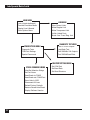


![2013 Gun List internet copy[2]](http://vs1.manualzilla.com/store/data/005851443_1-16b4e1bd3fc391c408d2005c48a2e336-150x150.png)