1
MITSUBISHI ELECTRIC
MELSEC FX Series
Programmable Controllers
User's Manual
(CC-Link V2)
FX3U-64CCL
01 07 2010
JY997D30401
Version E
MITSUBISHI ELECTRIC
INDUSTRIAL AUTOMATION
Safety Precautions
(Read these precautions before using.)
Before installation, operation, maintenance or inspection of this product, thoroughly read through and
understand this manual and the associated manuals. Also, take care to handle the module properly and
safely.
This manual classifies the safety precautions into two categories:
and
.
Indicates that incorrect handling may cause hazardous conditions, resulting in death or severe
injury.
Indicates that incorrect handling may cause hazardous conditions, resulting in medium or slight
personal injury or physical damage.
Depending on the circumstances, procedures indicated by
may also cause severe injury. In
any case, it is important to follow all usage directions. Store this manual in a safe place so that it can be taken
out and read whenever necessary. Always forward it to the end user.
1. DESIGN PRECAUTIONS
Reference
•
•
•
For the status of each station when the main unit stops calculation or when a communication error occurs in the
data link, thoroughly read the description of data link processing time in the CC-Link master module manual.
Construct an interlock circuit in the sequence program using the communication status information (BFM, SB, SW)
so that the system always works conservatively.
Erroneous outputs and malfunctions may cause accidents.
1) Setting to hold or clear the input information against data link error.
Remote outputs (RY) and remote registers (RWw) are held or cleared in accordance with the setting of BFM
#32.
0 (default): Data prior to the error is held.
Other than 0: Data prior to the error is cleared.
2) Setting to hold or clear the data against a stop in the main unit.
Remote inputs (RX) and remote registers (RWr) are held or cleared in accordance with the setting of BFM #33.
0 (default): Data prior to the stop is held.
Other than 0: Data prior to the stop is cleared.
When executing control (data changes) to an operating PLC, construct an interlock circuit in the sequence program
so that the entire system operates conservatively.
In addition, when executing control such as program changes and operation status changes (status control) to an
operating PLC, thoroughly read the manual and sufficiently confirm safety in advance.
Especially in control from external equipment to a PLC in a remote place, problems in the PLC may not be able to
be handled promptly due to abnormality in data transfer.
Construct an interlock circuit in the sequence program. At the same time, determine the actions in the system
between the external equipment and the PLC (Master station contains) for protection against abnormalities in data
transfer.
Make sure to include the following safety circuits outside the PLC to ensure safe system operation even during
external power supply problems or PLC failure.
Otherwise, malfunctions may cause serious accidents.
1) Above all, the following components should be included: an emergency stop circuit, a protection circuit, an
interlock circuit for opposite movements (such as normal vs. reverse rotation), and an interlock circuit (to prevent
damage to the equipment at the upper and lower positioning limits).
2) Note that when the PLC main unit detects an error during self diagnosis, such as a watchdog timer error, all
outputs are turned off. Also, when an error that cannot be detected by the PLC main unit occurs in an input/
output control block, output control may be disabled.
External circuits and mechanisms should be designed to ensure safe machinery operation in such cases.
16
Reference
•
•
Observe the following items. Failure to do so may cause incorrect data-writing through noise to the PLC and result
in PLC failure, machine damage or other accident.
1) Do not bundle the control line together with or lay it close to the main circuit or power line. As a guideline, lay the
control line at least 100mm (3.94") or more away from the main circuit or power line.
Noise may cause malfunctions.
2) Ground the shield wire or shield of a shielded cable. Do not use common grounding with heavy electrical
systems (refer to Subsection 5.1.2).
Do not apply excessive pressure to the power supply terminal block or CC-Link connection terminal block.
Excessive pressure may cause damage or error.
(1)
16
26
Safety Precautions
(Read these precautions before using.)
2. INSTALLATION PRECAUTIONS
Reference
•
Make sure to cut off all phases of the power supply externally before attempting installation or wiring work.
Failure to do so may cause electric shock or damage to the product.
23
Reference
•
•
•
•
•
•
•
•
Use the product within the generic environment specifications described in PLC main unit manual (Hardware
Edition). Never use the product in areas with excessive dust, oily smoke, conductive dusts, corrosive gas (salt air,
Cl2, H2S, SO2, or NO2), flammable gas, vibration or impacts, or expose it to high temperature, condensation, or
rain and wind. If the product is used in such conditions, electric shock, fire, malfunctions, deterioration or damage
may occur.
Do not touch the conductive parts of the product directly.
Doing so may cause device failures or malfunctions.
Install the product securely using a DIN rail or mounting screws.
Install the product on a flat surface.
If the mounting surface is rough, undue force will be applied to the PC board, thereby causing nonconformities.
When drilling screw holes or wiring, make sure that cutting and wiring debris do not enter the ventilation slits.
Failure to do so may cause fire, equipment failures or malfunctions.
Be sure to remove the dust proof sheet from the PLC's ventilation port when installation work is completed.
Failure to do so may cause fire, equipment failures or malfunctions.
Make sure to attach the top cover, offered as an accessory, before turning on the power or initiating operation after
installation or wiring work.
Failure to do so may cause electric shock.
Connect extension cables securely to their designated connectors.
Loose connections may cause malfunctions.
23
3. WIRING PRECAUTIONS
Reference
•
Make sure to cut off all phases of the power supply externally before attempting wiring work.
Failure to do so may cause electric shock or damage to the product.
26
Reference
•
•
•
•
•
•
•
Connect the DC power supply wiring to the dedicated terminals described in this manual.
If an AC power supply is connected to a DC input/output terminal or DC power supply terminal, the PLC will burn
out.
Perform class D grounding (grounding resistance: 100 or less) to the grounding terminal on the 64CCL with a wire
as thick as possible.
Do not use common grounding with heavy electrical systems (refer to Subsection 5.1.2).
Make sure to attach the top cover, offered as an accessory, before turning on the power or initiating operation after
installation or wiring work.
Failure to do so may cause electric shock.
When drilling screw holes or wiring, make sure that cutting and wiring debris do not enter the ventilation slits.
Failure to do so may cause fire, equipment failures or malfunctions.
For the CC-Link system, use CC-Link dedicated cables.
The performance of the CC-Link system cannot be guaranteed with any cable other than CC-Link dedicated cables.
For the maximum total extension length and the cable length between stations, observe the specification described
in the CC-Link master module manual.
With wiring outside the specification range, normal data transfer cannot be guaranteed.
Do not bundle the CC-Link exclusive cable together with or lay it close to the main circuit, high-voltage line, or load
line. As a guideline, lay the control line at least 100mm (3.94") or more away from the main circuit, high-voltage line,
or load line.
Otherwise, noise disturbance and/or surge induction are likely to take place.
Make sure to fix communication cables and power cables connected to the module by placing them in the duct or
clamping them.
Cables not placed in duct or not clamped may hang or shift, allowing them to be accidentally pulled, which may
result in malfunction or damage to the module and the cables.
(2)
26
Safety Precautions
(Read these precautions before using.)
Reference
•
•
When disconnecting a communication/power cable connected to the module, do not hold the cable area.
For a cable connected to a terminal block, loosen screws of the terminal block, then disconnect the cable.
If a cable is pulled while it is connected to a module, the module may malfunction or the module and the cable may
be damaged.
Make sure to properly wire the extension equipment in accordance with the following precautions.
Failure to do so may cause electric shock, equipment failures, a short-circuit, wire breakage, malfunctions, or
damage to the product.
- The disposal size of the cable end should follow the dimensions described in the manual.
- Tightening torque should follow the specifications in the manual.
26
4. STARTUP AND MAINTENANCE PRECAUTIONS
Reference
•
•
•
Do not touch any terminal while the PLC's power is on.
Doing so may cause electric shock or malfunctions.
Before cleaning or retightening terminals, cut off all phases of the power supply externally.
Failure to do so may cause electric shock.
Before modifying or disrupting the program in operation or running the PLC, carefully read through this manual and
the associated manuals and ensure the safety of the operation.
An operation error may damage the machinery or cause accidents.
26
Reference
•
•
•
Do not disassemble or modify the PLC.
Doing so may cause fire, equipment failures, or malfunctions.
For repair, contact your local Mitsubishi Electric distributor.
Turn off the power to the PLC before connecting or disconnecting any extension cable.
Failure to do so may cause equipment failures or malfunctions.
Turn off the power to the PLC before attaching or detaching the following devices.
Failure to do so may cause equipment failures or malfunctions.
- Display module, peripheral devices, expansion boards, and special adapters
- Terminal blocks, I/O extension units/blocks and special function units/blocks
27
5. DISPOSAL PRECAUTIONS
Reference
•
Please contact a certified electronic waste disposal company for the environmentally safe recycling and disposal of
your device.
16
6. TRANSPORTATION PRECAUTIONS
Reference
•
The PLC is a precision instrument. During transportation, avoid impacts larger than those specified in the general
specifications of the PLC main unit manual.
Failure to do so may cause failures in the PLC.
After transportation, verify the operations of the PLC.
(3)
16
MEMO
(4)
FX3U-64CCL User's Manual
FX3U-64CCL
User’s Manual
Manual number
JY997D30401
Manual revision
E
Date
7/2010
Foreword
This manual describes the FX3U-64CCL CC-Link interface block and should be read and understood before
attempting to install or operate the hardware.
Store this manual in a safe place so that you can take it out and read it whenever necessary. Always forward
it to the end user.
This manual confers no industrial property rights or any rights of any other kind, nor does it confer any patent licenses. Mitsubishi
Electric Corporation cannot be held responsible for any problems involving industrial property rights which may occur as a result of
using the contents noted in this manual.
© 2008 MITSUBISHI ELECTRIC CORPORATION
1
FX3U-64CCL User's Manual
Outline Precautions
• This manual provides information for the use of the FX3U-64CCL CC-Link interface block. The manual has
been written to be used by trained and competent personnel. The definition of such a person or persons is
as follows;
1) Any engineer who is responsible for the planning, design and construction of automatic equipment using
the product associated with this manual should be of a competent nature, trained and qualified to the
local and national standards required to fulfill that role. These engineers should be fully aware of all
aspects of safety with aspects regarding to automated equipment.
2) Any commissioning or maintenance engineer must be of a competent nature, trained and qualified to the
local and national standards required to fulfill the job. These engineers should also be trained in the use
and maintenance of the completed product. This includes being familiar with all associated manuals and
documentation for the product. All maintenance should be carried out in accordance with established
safety practices.
3) All operators of the completed equipment should be trained to use that product in a safe and coordinated
manner in compliance with established safety practices. The operators should also be familiar with
documentation that is connected with the actual operation of the completed equipment.
Note: the term 'completed equipment' refers to a third party constructed device that contains or uses the
product associated with this manual.
• This product has been manufactured as a general-purpose part for general industries, and has not been
designed or manufactured to be incorporated in a device or system used in purposes related to human life.
• Before using the product for special purposes such as nuclear power, electric power, aerospace, medicine
or passenger movement vehicles, consult with Mitsubishi Electric.
• This product has been manufactured under strict quality control. However when installing the product
where major accidents or losses could occur if the product fails, install appropriate backup or failsafe
functions into the system.
• When combining this product with other products, please confirm the standards and codes of regulation to
which the user should follow. Moreover, please confirm the compatibility of this product with the system,
machines, and apparatuses to be used.
• If there is doubt at any stage during installation of the product, always consult a professional electrical
engineer who is qualified and trained in the local and national standards. If there is doubt about the
operation or use, please consult the nearest Mitsubishi Electric distributor.
• Since the examples within this manual, technical bulletin, catalog, etc. are used as reference; please use it
after confirming the function and safety of the equipment and system. Mitsubishi Electric will not accept
responsibility for actual use of the product based on these illustrative examples.
• The content, specification etc. of this manual may be changed for improvement without notice.
• The information in this manual has been carefully checked and is believed to be accurate; however, if you
notice any doubtful point, error, etc., please contact the nearest Mitsubishi Electric distributor.
Registration
• The company name and the product name to be described in this manual are the registered trademarks or
trademarks of each company.
2
FX3U-64CCL User's Manual
Table of Contents
Table of Contents
SAFETY PRECAUTIONS .................................................................................................. (1)
Standards................................................................................................................................... 6
Certification of UL, cUL standards ....................................................................................................... 6
Compliance with EC directive (CE Marking) ........................................................................................ 6
Associated Manuals................................................................................................................ 10
Generic Names and Abbreviations Used in the Manual ...................................................... 11
Reading the Manual ................................................................................................................ 13
1. Introduction
1.1
1.2
1.3
1.4
Outline........................................................................................................................................... 14
External Dimensions and Part Names .......................................................................................... 14
Terminal layout.............................................................................................................................. 15
Power and status LEDs................................................................................................................. 15
2. Specification and function
2.1
2.2
2.3
2.4
14
16
General specifications................................................................................................................... 17
Power supply specification............................................................................................................ 17
Performance specification............................................................................................................. 17
Communication function................................................................................................................ 18
2.4.1 Data transfer between 64CCL and master station ........................................................................ 18
2.4.2 Summary of accessing the FX3G/FX3U/FX3UC main unit from another station
QCPU (Q mode) station. ............................................................................................................... 18
2.4.3 The accessing path to the FX3G/FX3U/FX3UC from another QCPU (Q mode) controller ............. 19
3. System Configuration
20
3.1 General configuration.................................................................................................................... 20
3.2 CC-Link network configuration ...................................................................................................... 21
3.3 Applicable PLC.............................................................................................................................. 21
3.3.1 Connectable PLC .......................................................................................................................... 21
3.3.2 Corresponding Q Series controllers when accessing via another station QCPU (Q mode).......... 21
3.4 Connection with PLC..................................................................................................................... 22
4. Installation
23
4.1 DIN rail mounting .......................................................................................................................... 24
4.2 Direct mounting ............................................................................................................................. 25
3
FX3U-64CCL User's Manual
5. Wiring, Start-up procedure
Table of Contents
26
5.1 Power supply wiring ...................................................................................................................... 28
5.1.1 Power supply wiring....................................................................................................................... 28
5.1.2 Grounding...................................................................................................................................... 28
5.2 Start-up procedure ........................................................................................................................ 29
5.2.1 64CCL summary start-up procedure ............................................................................................. 29
5.2.2 Hardware test ................................................................................................................................ 30
5.3 CC-Link wiring............................................................................................................................... 31
5.3.1 CC-Link cabling ............................................................................................................................. 31
5.3.2 Wiring with CC-Link cabling........................................................................................................... 31
5.4 Screw size and tightening torque .................................................................................................. 32
5.4.1 Terminal screw size and tightening torque .................................................................................... 32
5.4.2 Terminal block mounting screw size and tightening torque........................................................... 32
6. FX3U-64CCL setting (switch setting)
33
6.1 Station number setting .................................................................................................................. 33
6.2 Transmission rate setting, hardware test ...................................................................................... 34
6.3 Number of occupied stations, expanded cyclic setting ................................................................. 34
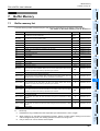
7. Buffer Memory
35
7.1 Buffer memory list ......................................................................................................................... 35
7.2 Buffer memory details ................................................................................................................... 36
7.2.1 [BFM#0 to #7] Remote I/O (RX/RY) .............................................................................................. 36
7.2.2 [BFM#8 to #23] Remote register (RWw/RWr) ............................................................................... 37
7.2.3 [BFM#24] Transmission rate, hardware test set value .................................................................. 38
7.2.4 [BFM#25] Communication status .................................................................................................. 39
7.2.5 [BFM#26] CC-Link model code ..................................................................................................... 39
7.2.6 [BFM#27] Set value of host station number .................................................................................. 40
7.2.7 [BFM#28] Number of occupied stations, expanded cyclic set value ............................................. 40
7.2.8 [BFM#29] Error code ..................................................................................................................... 41
7.2.9 [BFM#30] FX Series model code................................................................................................... 42
7.2.10 [BFM#32, #33] Treatment of link data ......................................................................................... 42
7.2.11 [BFM#36] Unit status ................................................................................................................... 42
7.2.12 [BFM#60 to 63] Consistency control............................................................................................ 43
7.2.13 [BFM#64 to 77] Remote input (RX) ............................................................................................. 46
7.2.14 [BFM#120 to 133] Remote output (RY) ....................................................................................... 48
7.2.15 [BFM#176 to 207] Remote register RWw.................................................................................... 50
7.2.16 [BFM#304 to 335] Remote register RWr ..................................................................................... 51
7.2.17 [BFM#512 to 543] Link special relay (SB) ................................................................................... 52
7.2.18 [BFM#768 to 1279] Link special register (SW) ............................................................................ 53
8. Program Example
55
8.1 System configuration..................................................................................................................... 55
8.2 Communication data sequence..................................................................................................... 57
8.3 FX3G/FX3U/FX3UC PLC program example .................................................................................. 58
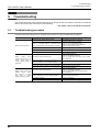
9. Troubleshooting
62
9.1 Troubleshooting procedure ........................................................................................................... 62
9.2 LED status check .......................................................................................................................... 63
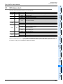
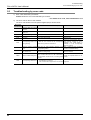
9.3 Troubleshooting by error code ...................................................................................................... 64
4
FX3U-64CCL User's Manual
Appendix A: Version Information
Table of Contents
65
Appendix A-1 Version information .............................................................................................. 65
Appendix A-1-1 Version check method .................................................................................................. 65
Appendix A-1-2 Version upgrade history................................................................................................ 65
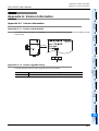
Appendix B: Differences with FX2N-32CCL
Appendix B-1
Appendix B-2
Appendix B-3
Appendix B-4
66
Differences with FX2N-32CCL.............................................................................. 66
List of buffer memory compatible with FX2N-32CCL............................................ 67
[BFM#25] Communication status comparison table............................................. 68
[BFM#29] Error code comparison table ............................................................... 69
Warranty................................................................................................................................... 71
Revised History ....................................................................................................................... 72
5
FX3U-64CCL User's Manual
Standards
Standards
Certification of UL, cUL standards
FX3U-64CCL units comply with the UL standards (UL, cUL).
UL, cUL File number :E95239
Regarding the standards that comply with the main unit, please refer to either the FX series product catalog or
consult with your nearest Mitsubishi product provider.
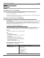
Compliance with EC directive (CE Marking)
This document does not guarantee that a mechanical system including this product will comply with the
following standards.
Compliance to EMC directive and LVD directive for the entire mechanical module should be checked by the
user / manufacturer. For more information please consult with your nearest Mitsubishi product provider.
Regarding the standards that comply with the main unit, please refer to either the FX series product catalog or
consult with your nearest Mitsubishi product provider.
Requirement for Compliance with EMC directive
The following products have shown compliance through direct testing (of the identified standards below) and
design analysis (through the creation of a technical construction file) to the European Directive for
Electromagnetic Compatibility (2004/108/EC) when used as directed by the appropriate documentation.
Attention
• This product is designed for use in industrial applications.
Note
• Manufactured by:
Mitsubishi Electric Corporation
2-7-3 Marunouchi, Chiyoda-ku, Tokyo, 100-8310 Japan
• Manufactured at:
Mitsubishi Electric Corporation Himeji Works
840 Chiyoda-machi, Himeji, Hyogo, 670-8677 Japan
• Authorized Representative in the European Community:
Mitsubishi Electric Europe B.V.
Gothaer Str. 8, 40880 Ratingen, Germany
Type: Programmable Controller (Open Type Equipment)
Models: MELSEC FX3U series manufactured
from March 1st, 2008
FX3U-64CCL
Standard
EN61131-2:2007
Programmable controllers
- Equipment requirements and tests
6
Remark
Compliance with all relevant aspects of the standard.
EMI
• Radiated Emissions
• Conducted Emissions
EMS
• Radiated electromagnetic field
• Fast Transient burst
• Electrostatic discharge
• High-energy surge
• Voltage drops and interruptions
• Conducted RF
• Power frequency magnetic field
FX3U-64CCL User's Manual
Standards
Caution to conform with EC Directives
• Installation in Enclosure
Programmable logic controllers are open-type devices that must be installed and used within conductive
control cabinets. Please use the programmable logic controller while installed within a conductive shielded
control cabinet. Please secure the cabinet door to the control cabinet (for conduction).
Installation within a control cabinet greatly affects the safety of the system and aids in shielding noise from the
programmable logic controller.
• Control cabinet
- The control cabinet must be conductive.
- Ground the control cabinet with the thickest possible grounding cable.
- To ensure that there is electric contact between the control cabinet and its door, connect the cabinet and
its doors with thick wires.
- In order to suppress the leakage of radio waves, the control cabinet structure must have minimal
openings. Also, wrap the cable holes with a shielding cover or other shielding devices.
- The gap between the control cabinet and its door must be as small as possible by attaching EMI gaskets
between them.
Shielding cover
Shielded cable
EMI gasket
Wires*1
*1.
These wires are used to improve the conductivity between the door and control cabinet.
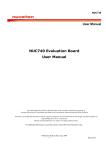
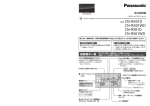
• Configuration example inside control cabinet
L N
Power
cable
24V DC power
supply
Ground
cable
24+ 24Main unit
FX3U-64CCL
DA DB DG SLD
CC-Link dedicated cable
Cable clamp
(AD75CK,
MITSUBISHI)
Ground
cable
Conductive control cabinet
• Wiring simplified diagram
Termi- Master
nating unit
resistor
(Blue)
DA
(White)
DB
(Yellow)
DG
SLD
FG
Other
station
FX3U-64CCL
(Blue)
(White)
(Yellow)
CC-Link
Dedicated
Cable
DA
DB
DG
SLD
(Blue)
(Blue)
(White)
(White)
(Yellow)
(Yellow)
CC-Link
Dedicated
Cable
Terminating
resistor
DA
DB
DG
SLD
FG
7
FX3U-64CCL User's Manual
Standards
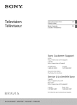
• Notes for compliance with EN61131-2:2007
General notes on the use of the power supply cable.
- The FX3U-64CCL unit requires that the cable used for power supply is 30m or less.
- When the cable used for power supply exceeds 30m, a noise filter (Ex. TDK-Lambda MBS1205-22 or
similar) should be placed on the 24V DC power cabling as close (within 500mm) to the FX3U-64CCL
termination points as possible, refer to following figure.
FX3U-64CCL
24V DC
8
Exceeding 30m
500mm or less
Noise
Filter
24V DC power
supply
FX3U-64CCL User's Manual
Standards
MEMO
9
FX3U-64CCL User's Manual
Associated Manuals
Associated Manuals
Only the installation manual is packed together with the FX3U-64CCL CC-Link interface block.
For a detailed explanation of the FX3U-64CCL CC-Link Interface block, refer to this manual.
For the operation of GX Developer, or hardware information and instructions on the PLC main unit, refer to
the respective manuals.
Refer to these manuals
Refer to the appropriate equipment manual
For a detailed explanation, refer to an additional manual
Title of manual
Document
number
Description
Model code
-
Manual for the Main Module
FX3G Series PLCs Main Unit
Supplied
Manual
FX3G Series
Hardware Manual
JY997D33401
Describes FX3G Series PLC specification for I/O,
wiring and installation extracted from the FX3G
Series User's Manual - Hardware Edition.
For details, refer to FX3G Series User's Manual Hardware Edition.
Additional
Manual
FX3G Series
User's Manual
- Hardware Edition
JY997D31301
Describes FX3G Series PLC specification details for
I/O, wiring, installation and maintenance.
09R521
-
FX3U Series PLCs Main Unit
Supplied
Manual
FX3U Series
Hardware Manual
JY997D18801
Describes FX3U Series PLC specification for I/O,
wiring and installation extracted from the FX3U User's
Manual - Hardware Edition.
For details, refer to FX3U Series User's Manual Hardware Edition.
Additional
Manual
FX3U Series
User's Manual
- Hardware Edition
JY997D16501
Describes FX3U Series PLC specification details for I/
O, wiring, installation and maintenance.
09R516
JY997D28601
Describes FX3UC(D,DSS) Series PLC specification
for I/O, wiring and installation extracted from the
FX3UC Series User's Manual - Hardware Edition.
For details, refer to FX3UC Series User's Manual Hardware Edition.
-
JY997D31601
Describes FX3UC-32MT-LT-2 specification for I/O,
wiring and installation extracted from the FX3UC
User's Manual - Hardware Edition.
For details, refer to FX3UC Series User's Manual Hardware Edition.
-
-
FX3UC Series PLCs Main Unit
Supplied
Manual
FX3UC(D,DSS) Series
Hardware Manual
Supplied
Manual
FX3UC-32MT-LT-2
Hardware Manual
Supplied
Manual
FX3UC-32MT-LT
Hardware Manual
(Only Japanese document)
JY997D12701
Describes FX3UC-32MT-LT specification for I/O,
wiring and installation extracted from the FX3UC
User's Manual - Hardware Edition.
For details, refer to FX3UC Series User's Manual Hardware Edition (Only Japanese document).
Additional
Manual
FX3UC Series
User's Manual
- Hardware Edition
JY997D28701
Describes FX3UC Series PLC specification details
for I/O, wiring, installation and maintenance.
09R519
JY997D16601
Describes FX3G/FX3U/FX3UC Series PLC
programming for basic/applied
instructions and devices.
09R517
Programming for FX3G/FX3U/FX3UC Series
Additional
Manual
FX3G/FX3U/FX3UC Series
Programming Manual
- Basic & Applied
Instruction Edition
Manuals for FX3U-64CCL CC-Link Interface Block
10
Supplied
Manual
FX3U-64CCL
Installation Manual
JY997D29801
Describes FX3U-64CCL CC-Link interface block
specification for installation extracted from the FX3U64CCL User's Manual.
For details, refer to FX3U-64CCL User's Manual.
-
Additional
Manual
FX3U-64CCL
User's Manual
(This Manual)
JY997D30401
Describes FX3U-64CCL CC-Link interface block
details.
09R718
FX3U-64CCL User's Manual
Generic Names and Abbreviations Used in the Manual
Generic Names and Abbreviations Used in the Manual
Generic name or abbreviation
Description
PLC
FX3G series
FX3G PLC or main unit
FX3U series
FX3U PLC or main unit
FX3UC series
FX3UC PLC or main unit
Generic name for FX3G Series PLC
Generic name for FX3G Series PLC main unit
Generic name for FX3U Series PLC
Generic name for FX3U Series PLC main unit
Generic name for FX3UC Series PLC
Generic name for FX3UC Series PLC main unit
Expansion board
Expansion board
Generic name for expansion board
The number of connectable units, however, depends on the type of main unit.
To check the number of connectable units, refer to the User's Manual - Hardware Edition of the main
unit to be used for your system.
Special adapter
Special adapter
Generic name for high-speed input/output special adapter, communication special adapter, and
analog special adapter
The number of connectable units, however, depends on the type of main unit.
To check the number of connectable units, refer to the User's Manual - Hardware Edition of the main
unit to be used for your system.
Extension equipment
I/O extension unit/block
Generic name for input/output powered extension unit and input/output extension block
The number of connectable units, however, depends on the type of main unit.
To check the number of connectable units, refer to the User's Manual - Hardware Edition of the main
unit to be used for your system.
Special function unit/block or
Special extension unit
Generic name for special function unit and special function block
The number of connectable units, however, depends on the type of main unit.
To check the number of connectable units, refer to the User's Manual - Hardware Edition of the main
unit to be used for your system.
Special function unit
Generic name for special function unit
Special function block
Generic name for special function block
The number of connectable units, however, depends on the type of main unit.
To check the number of connectable units, refer to the User's Manual - Hardware Edition of the main
unit to be used for your system.
64CCL
Abbreviated name for FX3U-64CCL
Optional unit
Memory cassette
FX3G-EEPROM-32L, FX3U-FLROM-16, FX3U-FLROM-64, FX3U-FLROM-64L
Battery
FX3U-32BL
FX Series terminal block
FX-16E-TB, FX-32E-TB, FX-16EX-A1-TB, FX-16EYR-TB, FX-16EYT-TB, FX-16EYT-H-TB,
FX-16EYS-TB, FX-16E-TB/UL, FX-32E-TB/UL, FX-16EYR-ES-TB/UL, FX-16EYT-ES-TB/UL,
FX-16EYT-ESS-TB/UL, FX-16EYS-ES-TB/UL
Peripheral unit
Peripheral unit
Generic name for programming software, handy programming panel, and indicator
Programming tool
Programming tool
Generic name for programming software and handy programming panel
Programming software
Generic name for programming software
GX Developer
Generic name for SW
FX-PCS/WIN(-E)
Generic name for FX-PCS/WIN or FX-PCS/WIN-E programming software package
Handy programming panel (HPP)
D5C-GPPW-J/SW
D5C-GPPW-E programming software package
Generic name for FX-30P, FX-20P(-E) and FX-10P(-E)
11
FX3U-64CCL User's Manual
Generic Names and Abbreviations Used in the Manual
Generic name or abbreviation
Description
Indicator
GOT1000 series
Generic name for GT16, GT15, GT11 and GT10
GOT-900 series
Generic name for GOT-A900 series and GOT-F900 series
GOT-A900 series
Generic name for GOT-A900 series
GOT-F900 series
Generic name for GOT-F900 series
ET-940 series
Generic name for ET-940 series
Only manuals in Japanese are available for these products
Manual
12
FX3G Hardware Edition
FX3G Series User's Manual - Hardware Edition
FX3U Hardware Edition
FX3U Series User's Manual - Hardware Edition
FX3UC Hardware Edition
FX3UC Series User's Manual - Hardware Edition
Programming manual
FX3G/FX3U/FX3UC Series Programming Manual - Basic and Applied Instructions Edition
Communication control Edition
FX Series User's Manual - Data Communication Edition
Analog control Edition
FX3G/FX3U/FX3UC Series User's Manual - Analog Control Edition
Positioning control Edition
FX3G/FX3U/FX3UC Series User's Manual - Positioning Control Edition
FX3U-64CCL User's Manual
Reading the Manual
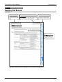
Reading the Manual
Shows the manual title.
Shows the title of the chapter and the title
Indexes the chapter number.
This area shows the
manual title for the current
page.
of the section.
This area shows the title of the chapter and the
title of the section for the current page.
The right side of each page
indexes the chapter number
for the page currently opened.
Shows the reference.
The " " mark indicates
a reference destination
and reference manual.
The above is different from the actual page, as it is provided for explanation only.
13
1 Introduction
FX3U-64CCL User's Manual
1.
1.1
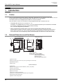
1.1 Outline
Introduction
Outline
The CC-Link interface block FX3U-64CCL (hereinafter called 64CCL) is a special function block to connect
the FX3G/FX3U/FX3UC Series programmable logic controller to a CC-Link network.
The 64CCL works as an intelligent device station on a CC-Link network.
Only one 64CCL unit can be connected to a single programmable logic controller main unit.
• Compatible with CC-Link Ver. 2.00 and Ver. 1.10
The 64CCL is compatible with CC-Link Ver. 2.00, and enables expanded cyclic transmission to facilitate
the handling of applications requiring multiple data processing.
Ver. 1.10 is also supported by the 64CCL.
• When accessing the FX3G/FX3U/FX3UC main unit from another station QCPU (Q mode) with
GX Developer is required. Access is carried out by the QCPU (Q mode) connected to the FX3G/FX3U/
FX3UC main unit via CC-Link. (The corresponding version of GX Developer for FX3U/FX3UC PLCs is
Ver.8.72A or later. The corresponding version of GX Developer for FX3G PLCs is Ver.8.78G or later.)
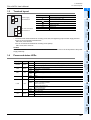
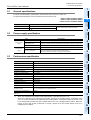
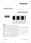
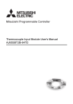
External Dimensions and Part Names
X
7 89
7 89
01
4
56
80(3.15")
(mounting hole pitch)
90(3.55")
10
1
01
23
STATION
NO.
B RATE STATION
BC D E
BC D E
78 9 A
DG SLD
DA DB
[7]
F 012
34 5 6
COM
SETTING
F 012
34 5 6
55(2.17")
X
[6]
9(0.36")
4(0.16")
[9]
23
FX3U-64CCL
[8]
FX3U-64CCL
POWER
[5]
2424+
RUN
ERR.
L RUN
L ERR.
SD
RD
56
[2]
Without top cover
78 9 A
[1]
2-φ4.5 mounting holes
[3]
[4]
4
1.2
[10]
[13] [12] [11]
87(3.43")
Unit: mm (inches)
MASS (Weight): 0.3kg (0.66lbs)
Accessories: Label for indication of
special unit/block number,
Dust Proof sheet,
Manual supplied with product
[1] Extension cable
[2] Direct mounting hole: 2 holes of φ4.5 (0.18") (mounting screw: M4 screw)
[3] POWER LED (green)
[4] Status LEDs
Refer to Section 1.4
[5] Name plate
[6] DIN rail mounting groove (DIN rail: DIN46277, 35mm (1.38") width)
[7] DIN rail mounting hook
[8] Power supply terminal block
[9] Extension connector
[10] CC-Link connection terminal block
[11] Number of occupied stations and expanded cyclic setting switch
[12] Transmission rate setting switch
[13] Station number setting switch
14
1 Introduction
FX3U-64CCL User's Manual
1
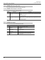
Terminal layout
Terminal name
24-
24+
Power supply
terminal block
Introduction
1.3
1.3 Terminal layout
Description
24+
24V DC power supply, + side
24-
24V DC power supply, - side
2
DA
DA
Send/receive data
DB
Send/receive data
DG
Data ground
SLD
Shield
3
System
Configuration
SLD
DB
DG
CC-Link connection
terminal block
Specification
and function
Ground terminal (Functional ground)
• Terminal screw and terminal block mounting screw size, and tightening torque Power supply terminal
block, CC-Link connection terminal block:
M3 screw, 42 to 58 N.cm
CC-Link connection terminal block mounting screw (black):
M3.5 screw, 66 to 91 N.cm
4
Installation
Caution
CC-Link connection terminal block can be detached or attached. Make sure to cut off all phases of the power
supply externally.
Wiring, Start-up
procedure
1.4
Power and status LEDs
Color
POWER
Green
RUN
Green
Red
L RUN
Green
L ERR.
Red
Green
RD
Green
6
Power is not being supplied from the external power supply (24V DC).
ON
Power is being supplied from the external power supply (24V DC).
OFF
64CCL has failed.
ON
Under 64CCL normal operation.
OFF
No errors.
ON
Error in the settings, error in the parameter details, error with the communication, error with the
H/W.
OFF
Offline.
ON
Data link is being executed.
OFF
No communication error.
Flicker
The switch setting was changed after start.
There is no terminating resistor.
Influence from noise.
ON
There is a data linking error.
There is a setting error.
OFF
Data is not being sent.
ON
Data is being sent.
OFF
Data is not being received.
ON
Data is being received.
7
8
Program
Example
SD
OFF
Description
Buffer Memory
ERR.
Status
FX3U-64CCL
setting (switch
setting)
LED display
5
9
Troubleshooting
A
Version
Information
15
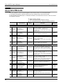
2 Specification and function
FX3U-64CCL User's Manual
2.
Specification and function
DESIGN PRECAUTIONS
•
•
•
•
For the status of each station when the main unit stops calculation or when a communication error occurs in the data link, thoroughly
read the description of data link processing time in the CC-Link master module manual. Construct an interlock circuit in the sequence
program using the communication status information (BFM, SB, SW) so that the system always works conservatively.
Erroneous outputs and malfunctions may cause accidents.
1) Setting to hold or clear the input information against data link error.
Remote outputs (RY) and remote registers (RWw) are held or cleared in accordance with the setting of BFM #32.
0 (default): Data prior to the error is held.
Other than 0: Data prior to the error is cleared.
2) Setting to hold or clear the data against a stop in the main unit.
Remote inputs (RX) and remote registers (RWr) are held or cleared in accordance with the setting of BFM #33.
0 (default): Data prior to the stop is held.
Other than 0: Data prior to the stop is cleared.
When executing control (data changes) to an operating PLC, construct an interlock circuit in the sequence program so that the entire
system operates conservatively.
In addition, when executing control such as program changes and operation status changes (status control) to an operating PLC,
thoroughly read the manual and sufficiently confirm safety in advance.
Especially in control from external equipment to a PLC in a remote place, problems in the PLC may not be able to be handled
promptly due to abnormality in data transfer.
Construct an interlock circuit in the sequence program. At the same time, determine the actions in the system between the external
equipment and the PLC (Master station contains) for protection against abnormalities in data transfer.
Make sure to include the following safety circuits outside the PLC to ensure safe system operation even during external power supply
problems or PLC failure.
Otherwise, malfunctions may cause serious accidents.
1) Above all, the following components should be included: an emergency stop circuit, a protection circuit, an interlock circuit for
opposite movements (such as normal vs. reverse rotation), and an interlock circuit (to prevent damage to the equipment at the
upper and lower positioning limits).
2) Note that when the PLC main unit detects an error during self diagnosis, such as a watchdog timer error, all outputs are turned off.
Also, when an error that cannot be detected by the PLC main unit occurs in an input/output control block, output control may be
disabled.
External circuits and mechanisms should be designed to ensure safe machinery operation in such cases.
DESIGN PRECAUTIONS
•
•
Observe the following items. Failure to do so may cause incorrect data-writing through noise to the PLC and result in PLC failure,
machine damage or other accident.
1) Do not bundle the control line together with or lay it close to the main circuit or power line. As a guideline, lay the control line at
least 100mm (3.94") or more away from the main circuit or power line.
Noise may cause malfunctions.
2) Ground the shield wire or shield of a shielded cable.
Do not use common grounding with heavy electrical systems (refer to Subsection 5.1.2).
Do not apply excessive pressure to the power supply terminal block or CC-Link connection terminal block.
Excessive pressure may cause damage or error.
DISPOSAL PRECAUTIONS
•
Please contact a certified electronic waste disposal company for the environmentally safe recycling and disposal of your device.
TRANSPORTATION PRECAUTIONS
•
16
The product is a precision instrument. During transportation, avoid any impacts. Failure to do so may cause failures in the product.
After transportation, verify the operations of the product.
2 Specification and function
FX3U-64CCL User's Manual
1
General specifications
Item
Specification
Dielectric withstand voltage
Insulation resistance
5M
Between all terminals and ground terminal
or more by 500V DC Megger
3
System
Configuration
2.2
500V AC for one minute
Power supply specification
Item
Internal power
supply
4
24V DC +20% -15% Ripple (p-p) within 5%
Permitted instantaneous
power failure time
Operation continues when the instantaneous power failure is shorter than PS1:1ms.
Current consumption
220mA
Power supply voltage
5V DC
Current consumption
5V DC of PLC is not used.
(5V DC is converted from 24V DC external power supply.)
Make sure to observe the power-on timing and the procedure.
5
Wiring, Start-up
procedure
2.3
Specification
Power supply voltage
Performance specification
Item
6
Specification
Ver.2.00 (Ver.1.10 also
supported.)*1
Intelligent device station
Station number
1 to 64
Transmission rate
156Kbps/625Kbps/2.5Mbps/5Mbps/10Mbps
Transmission distance
In accordance with the CC-Link specification. Refer to the PLC main unit manual for details.
Number of occupied stations
1 to 4 stations
Setting items
Station number, Transmission rate, Number of occupied stations, Expanded cyclic setting
Broadcast polling system
Synchronous method
Flag synchronization method
Encoding method
NRZI method
Transmission path type
Bus (RS-485)
Transmission format
Conforms to HDLC
Error control method
CRC(X16+X12+X5+1)
Connection cable
CC-Link dedicated cable/ CC-Link dedicated high-performance cable/
Ver.1.10 compatible CC-Link dedicated cable
Number of I/O occupied points
8 points
8
Program
Example
Communication method
7
Buffer Memory
Station type
FX3U-64CCL
setting (switch
setting)
CC-Link applicable version
Number of connectable units to the
1
main unit
9
When the expanded cyclic setting is the single setting, it operates using Ver.1.10.
When the expanded cyclic setting is the double, quadruple or octuple setting, it operates using
Ver.2.00. Check the status of the expanded cyclic setting switch of the 64CCL. When the 64CCL is set
to the single setting, please set up the master station as a Ver.1 intelligent device station. When the
64CCL is set to the double, quadruple or octuple, please set up the master station as a Ver.2
intelligent device station.
Troubleshooting
*1.
Installation
External power
supply
2
Specification
and function
For items not listed below, specifications are the same as the of the PLC main unit.
For general specifications, refer to the manual of the PLC main unit.
→ Refer to FX3G Hardware Edition
→ Refer to FX3U Hardware Edition
→ Refer to FX3UC Hardware Edition
Introduction
2.1
2.1 General specifications
A
Version
Information
17
2 Specification and function
FX3U-64CCL User's Manual
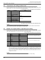
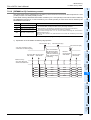
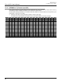
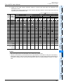
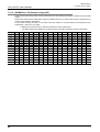
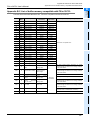
2.4 Communication function
• Expanded cyclic setting and number of link points (The number of points of bit (RX)/(RY) includes system
area points. For details, refer to the Section 7.2.)
CC-Link Ver.1.10
Expanded cyclic setting
Occupies 1 station
Occupies 2 stations
Occupies 3 stations
Occupies 4 stations
CC-Link Ver.2.00
Single
Double
Quadruple
Octuple
bit (RX)
32 points
32 points
64 points
128 points
bit (RY)
32 points
32 points
64 points
128 points
word (RWw)
4 points
8 points
16 points
32 points
word (RWr)
4 points
8 points
16 points
32 points
bit (RX)
64 points
96 points
192 points
bit (RY)
64 points
96 points
192 points
word (RWw)
8 points
16 points
32 points
32 points
word (RWr)
8 points
16 points
bit (RX)
96 points
160 points
bit (RY)
96 points
160 points
word (RWw)
12 points
24 points
word (RWr)
12 points
24 points
bit (RX)
128 points
224 points
bit (RY)
128 points
224 points
word (RWw)
16 points
32 points
word (RWr)
16 points
32 points
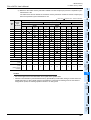
2.4
Communication function
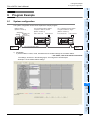
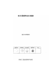
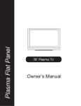
2.4.1
Data transfer between 64CCL and master station
FX3G/FX3U/FX3UC main unit
FX3U extension bus
FX3U-64CCL
BFM (Buffer memory)
M (auxiliary relay) etc.
M (auxiliary relay) etc.
D (data resister) etc.
D (data resister) etc.
TO instruction
FROM instruction
FROM instruction
TO instruction
RX: Remote input
CC-Link
Cyclic,
Expanded cyclic
-
-
-
-
-
Q master station
RX: Remote input
RY: Remote output
RY: Remote output
RWw(Remote register)
RWw(Remote register)
RWr(Remote register)
RWr(Remote register)
Data is transferred using FROM/TO instructions via the buffer memory (or direct specification of buffer
memory) between the FX3G/FX3U/FX3UC PLC and the 64CCL. Data is replaced with internal devices (such as
M, R and D), and used in sequence programs.
Cyclic transmission and extended cyclic transmission are available between the master station and the
64CCL.
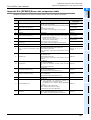
2.4.2
Summary of accessing the FX3G/FX3U/FX3UC main unit from another station QCPU
(Q mode) station.
The FX3G/FX3U/FX3UC which is connected to the 64CCL can be accessed*1 via CC-Link from QCPU (Q
mode) master / local station when GX Developer is used. (The corresponding version of GX Developer for
FX3U /FX 3UC PLCs is Ver.8.72A or later. The corresponding version of GX Developer for FX3G PLCs is
Ver.8.78G or later. For settings, refer to the GX Developer manuals.)
Accessing permits write and read, verify, carry out device batch monitoring and complete device test.
*1.
18
When setting station 64, the accessing function to the FX3G/FX3U/FX3UC PLC main unit cannot be
used.
2 Specification and function
FX3U-64CCL User's Manual
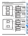
The accessing path to the FX3G/FX3U/FX3UC from another QCPU (Q mode) controller
From the master station/local station of the QCPU (Q mode), the FX 3G/FX3U/FX3UC programmable logic
controller main unit can be accessed. The communication path of CC-Link is illustrated as follows.
(Please refer to the GX Developer manual for routing details)
→ Refer to the GX Developer Operating Manual.
PC
GX Developer
etc.
Q
QCPU
(Q mode) master
station
*1
2
Specification
and function
1) The path when accessing from the master QCPU (Q mode) station
1
Introduction
2.4.3
2.4 Communication function
3
System
Configuration
CC-Link
4
*1.
Installation
FX3G/FX3U/FX3UC
main unit
FX3U64CCL
Direct connection or connection using the GOT transparent mode.
5
Wiring, Start-up
procedure
2) The path when accessing from a local QCPU (Q mode) station
Q
QCPU
(Q mode) master
station
6
FX3U-64CCL
setting (switch
setting)
CC-Link
PC
GX Developer
etc.
7
QCPU
(Q mode)
*1.
Q
local
station
FX3G/FX3U/FX3UC
main unit
Buffer Memory
*1
FX3U64CCL
Direct connection or connection using the GOT transparent mode.
8
Program
Example
9
Troubleshooting
A
Version
Information
19
3 System Configuration
FX3U-64CCL User's Manual
3.
3.1
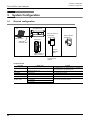
3.1 General configuration
System Configuration
General configuration
PC
FX3G/FX3U PLC
Only one 64CCL is
connectable
FX3U-64CCL
GX Developer
FX3UC PLC
USB cable
RS-232C cable
Other extension
units/blocks
RUN
ERR.
L RUN
L ERR.
SD
RD
POWER
FX3U-64CCL
FX2NC-CNV-IF or
FX3UC-1PS-5V
CC-Link
dedicated
cable
To the CC-Link
network
Component list
Part name
Model name
CC-Link interface block
FX3U-64CCL
PLC
FX3G/FX3U/FX3UC PLC
PC software
GX Developer
PC
FX-USB-AW
RS-232C cable
FX-232AWC-H
PLC programming software
-
USB cable
Remarks
An FX2NC-CNV-IF or FX3UC-1PS-5V is necessary to
connect the 64CCL with the FX3UC PLC.
Connection cable between FX PLC and PC
F2-232CAB-1
FX-422CAB0
20
PC connection cable and interface
3 System Configuration
FX3U-64CCL User's Manual
1
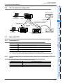
CC-Link network configuration
Introduction
3.2
3.2 CC-Link network configuration
PC
2
Remote I/O station
Specification
and function
Master station
GX Developer
Terminating resistor
(indispensable)
Cyclic transmission
Expanded cyclic transmission
3
System
Configuration
Terminating resistor
(indispensable)
Accessing
via QCPU
PC
4
Local station
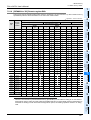
Applicable PLC
3.3.1
Connectable PLC
Model name
Remote device station
5
Wiring, Start-up
procedure
3.3
FX3G/FX3U/FX3UC PLC FX3U-64CCL
Intelligent device station
Installation
GX Developer
6
Applicability
Ver. 1.00 (from the first product) and later
Only one 64CCL unit can be connected to a main unit.
FX3U Series PLC
Ver. 2.20 (from the first product) and later
Only one 64CCL unit can be connected to a main unit.
FX3UC Series PLC*1
Ver. 2.20 (from products manufactured in May, 2005 with SER No. 55****) and later
Only one 64CCL unit can be connected to a main unit.
FX3U-64CCL
setting (switch
setting)
FX3G Series PLC
7
*1.
3.3.2
An FX2NC-CNV-IF or FX3UC-1PS-5V is necessary to connect the 64CCL with the FX3UC PLC.
Corresponding Q Series controllers when accessing via another station QCPU (Q
mode)
QCPU(Q mode) series name
Corresponding model name
Q00JCPU,Q00CPU,Q01CPU
High performance model QCPU
Q02CPU,Q02HCPU,Q06HCPU,Q12HCPU,Q25HCPU
Universal model QCPU
Q02UCPU,Q03UDCPU,Q04UDHCPU,Q06UDHCPU,Q13UDHCPU,Q26UDHCPU
8
Program
Example
CC-Link system master / local unit QJ61BT11N is required.
Basic model QCPU
Buffer Memory
The version number can be checked by monitoring the last three digits of D8001.
9
Troubleshooting
A
Version
Information
21
3 System Configuration
FX3U-64CCL User's Manual
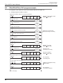
3.4
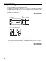
3.4 Connection with PLC
Connection with PLC
The 64CCL connects with an FX3U PLC via an extension cable.
The 64CCL is handled as a special extension block of the PLC. The unit number of the 64CCL is
automatically assigned No.0 to No.7 (Unit No.1 to No.7 is assigned when the main unit is an FX3UC-32MTLT(-2).) starting from the special function unit/block closest to the PLC main unit. (This unit number is used for
the designation of a FROM/TO instruction.)
For details on the assignment of the I/O number and unit number of the PLC, refer to the following manual
corresponding to the connected PLC.
→ FX3G Hardware Edition
→ FX3U Hardware Edition
→ FX3UC Hardware Edition
Other
extension
FX3U-64CCL
units/blocks
FX3G/FX3U PLC
MOTOR-X
START
DOG
INT0
INT1
A
B
MOTOR-Y
START
DOG
INT0
INT1
A
B
RUN
ERR.
L RUN
L ERR.
SD
RD
X-READY
Y-READY
X-ERROR
Y-ERROR
POWER
POWER
FX3U-64CCL
Other
FX3UC PLC FX3U-64CCL extension
units/blocks
RUN
ERR.
L RUN
L ERR.
SD
RD
POWER
MOTOR-X
START
DOG
INT0
INT1
A
B
MOTOR-Y
START
DOG
INT0
INT1
A
B
X-READY
Y-READY
X-ERROR
Y-ERROR
POWER
FX3U-64CCL
FX2NC-CNV-IF
• Only one 64CCL unit can be connected to the FX3G/FX3U/FX3UC PLC.
• An FX2NC-CNV-IF or FX3UC-1PS-5V is necessary to connect the 64CCL with the FX3UC PLC.
• The optional FX0N-65EC (FX0N-30EC) and FX2N-CNV-BC are necessary to lengthen the extension cable.
• The number of I/O points occupied by the 64CCL is eight. Make sure that the total number of I/O points
(occupied I/O points) of the main unit, power extension unit(s) extension block(s) and the number of points
occupied by special function blocks does not exceed the maximum number of I/O points of the PLC.
For information on the maximum number of I/O points of the PLC, refer to the respective product manual.
→ FX3G Hardware Edition
→ FX3U Hardware Edition
→ FX3UC Hardware Edition
22
4 Installation
FX3U-64CCL User's Manual
1
Introduction
4.
Installation
2
Specification
and function
INSTALLATION PRECAUTIONS
•
Make sure to cut off all phases of the power supply externally before attempting installation work.
Failure to do so may cause electric shock or damage to the product.
3
•
•
•
•
•
6
FX3U-64CCL
setting (switch
setting)
7
Buffer Memory
Only one 64CCL unit can be connected to the right side of the main unit, extension unit or extension block.
To connect to an FX 3UC PLC or FX 2NC PLC extension block, the FX 2NC -CNV-IF or FX 3UC -1PS-5V is
necessary.
For details, refer to the respective PLC manual.
→ Refer to the FX3G Hardware Edition
→ Refer to the FX3U Hardware Edition
→ Refer to the FX3UC Hardware Edition
The 64CCL may be installed in a control cabinet with a 35 mm wide DIN46277 DIN rail mounting or M4 screw
direct mounting.
5
Wiring, Start-up
procedure
•
4
Installation
•
•
Use the product within the generic environment specifications described in Section 2.1 of this manual. Never use the product in areas
with excessive dust, oily smoke, conductive dusts, corrosive gas (salt air, Cl2, H2S, SO2 or NO2), flammable gas, vibration or
impacts, or exposed to high temperature, condensation, or rain and wind. If the product is used in such conditions, electric shock, fire,
malfunctions, deterioration or damage may occur.
Do not touch the conductive parts of the product directly.
Doing so may cause device failures or malfunctions.
Install the product securely using a DIN rail or mounting screws.
Install the product on a flat surface.
If the mounting surface is rough, undue force will be applied to the PC board, thereby causing nonconformities.
When drilling screw holes or wiring, make sure that cutting and wiring debris do not enter the ventilation slits.
Failure to do so may cause fire, equipment failures or malfunctions.
Be sure to remove the dust proof sheet from the PLC's ventilation port when installation work is completed.
Failure to do so may cause fire, equipment failures or malfunctions.
Make sure to attach the top cover, offered as an accessory, before turning on the power or initiating operation after installation or
wiring work.
Failure to do so may cause electric shock.
Connect extension cables securely to their designated connectors.
Loose connections may cause malfunctions.
System
Configuration
INSTALLATION PRECAUTIONS
8
Program
Example
9
Troubleshooting
A
Version
Information
23
4 Installation
FX3U-64CCL User's Manual
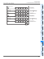
4.1
4.1 DIN rail mounting
DIN rail mounting
The product may be mounted on a 35mm wide DIN46277 (DIN rail).
1
2
Fit the upper edge (A in the figure to the right) of the DIN
rail mounting groove onto the DIN rail.
Push the product onto the DIN rail.
• An interval space of 1 to 2 mm (0.04" to 0.08") between each unit is necessary.
3
Connect the extension cable.
Connect the extension cable (B in the figure to the right) to
the main unit, I/O extension unit/block or special function
unit/block on the left side of the product.
For information on the extension cable connection procedure, refer to the respective product PLC manual.
→ Refer to the FX3G Hardware Edition
→ Refer to the FX3U Hardware Edition
→ Refer to the FX3UC Hardware Edition
• Example of anchoring
1 to 2mm
(0.04" to 0.08")
FX3G/FX3U
Series main unit
1 to 2mm
(0.04" to 0.08")
FX3U-64CCL
Other extension
equipment
DIN rail
1 to 2mm
(0.04" to 0.08")
FX3UC Series
main unit
1 to 2mm
(0.04" to 0.08")
FX3U-64CCL
DIN rail
FX2NC-CNV-IF or
FX3UC-1PS-5V
24
Other extension
equipment
B
4 Installation
FX3U-64CCL User's Manual
1
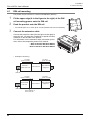
Direct mounting
1
3
System
Configuration
2
Create mounting holes in the mounting surface according to the external dimensions
diagram.
Fit the 64CCL (A in the figure to the right) to
the mounting holes and tighten with M4
screws (B in the figure to the right).
4
FX
3U
-48
M
IN 0
10
→ For dimensions, refer to Section 1.2.
0
10
3
Connect the extension cable.
2
12
1
3
13
4
14
5
15
6
16
11
7
20
17
21
22
23
24
25
PO
PO
WER
WER
2
12
3
13
4
14
5
15
6
16
7
26
27
RU
RU
N
N
BA
BA
TT
TT
ER
RO
RO
R R
ER
20
17
21
22
23
24
25
26
27
5
B
Wiring, Start-up
procedure
Connect the extension cable to the main unit, I/O extension unit/block or special function unit/block on the left side
of the product.
(Refer to Step 3 in Section 4.1.)
For information on the extension cable connection procedure, refer to the respective PLC manual.
1
11
OU
T
Installation
For the screw position and quantity, refer to the dimensioned drawing specified below.
A
B
6
FX3U-64CCL
setting (switch
setting)
→ Refer to the FX3G Hardware Edition
→ Refer to the FX3U Hardware Edition
→ Refer to the FX3UC Hardware Edition
• Example of anchoring
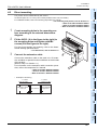
FX3U-64CCL
Buffer Memory
FX3G/FX3U Series
main unit
7
1 to 2mm
(0.04" to 0.08")
1 to 2mm
(0.04" to 0.08")
2
Specification
and function
The product can be installed directly with screws.
An interval space of 1 to 2 mm (0.04" to 0.08") between each unit is necessary.
For installation details, refer to the following respective PLC manual.
→ For mounting hole pitches, refer to Section 1.2.
→ Refer to the FX3G Hardware Edition
→ Refer to the FX3U Hardware Edition
→ Refer to the FX3UC Hardware Edition
Introduction
4.2
4.2 Direct mounting
other extension
equipment
8
Program
Example
(+ shows the M4 screw)
9
Troubleshooting
A
Version
Information
25
5 Wiring, Start-up procedure
FX3U-64CCL User's Manual
5.
Wiring, Start-up procedure
DESIGN PRECAUTIONS
•
•
Observe the following items. Failure to do so may cause incorrect data-writing through noise to the PLC and result in PLC failure,
machine damage or other accident.
1) Do not bundle the control line together with or lay it close to the main circuit or power line. As a guideline, lay the control line at
least 100mm (3.94") or more away from the main circuit or power line.
Noise may cause malfunctions.
2) Ground the shield wire or shield of a shielded cable. Do not use common grounding with heavy electrical systems (refer to
Subsection 5.1.2).
Do not apply excessive pressure to the power supply terminal block or CC-Link connection terminal block.
Excessive pressure may cause damage or error.
WIRING PRECAUTIONS
•
Make sure to cut off all phases of the power supply externally before attempting installation or wiring work.
Failure to do so may cause electric shock.
WIRING PRECAUTIONS
•
•
•
•
•
•
•
•
•
Connect the DC power supply wiring to the dedicated terminals described in this manual.
If an AC power supply is connected to a DC input/output terminal or DC power supply terminal, the PLC will burn out.
Perform class D grounding (grounding resistance: 100 or less) to the grounding terminal on the 64CCL with a wire as thick as
possible.
Do not use common grounding with heavy electrical systems (refer to Subsection 5.1.2).
Make sure to attach the top cover, offered as an accessory, before turning on the power or initiating operation after installation or
wiring work.
Failure to do so may cause electric shock.
When drilling screw holes or wiring, make sure that cutting and wiring debris do not enter the ventilation slits.
Failure to do so may cause fire, equipment failures or malfunctions.
For the CC-Link system, use CC-Link dedicated cables.
The performance of the CC-Link system cannot be guaranteed with any cable other than CC-Link dedicated cables.
For the maximum total extension length and the cable length between stations, observe the specification described in the CC-Link
master module manual.
With wiring outside the specification range, normal data transfer cannot be guaranteed.
Do not bundle the CC-Link exclusive cable together with or lay it close to the main circuit, high-voltage line, or load line. As a
guideline, lay the control line at least 100mm (3.94") or more away from the main circuit, high-voltage line, or load line.
Otherwise, noise disturbance and/or surge induction are likely to take place.
Make sure to fix communication cables and power cables connected to the module by placing them in the duct or clamping them.
Cables not placed in duct or not clamped may hang or shift, allowing them to be accidentally pulled, which may result in malfunction or
damage to the module and the cables.
When disconnecting a communication/power cable connected to the module, do not hold the cable area.
For a cable connected to a terminal block, loosen screws of the terminal block, then disconnect the cable.
If a cable is pulled while it is connected to a module, the module may malfunction or the module and the cable may be damaged.
Make sure to properly wire the extension equipment in accordance with the following precautions.
Failure to do so may cause electric shock, equipment failures, a short-circuit, wire breakage, malfunctions, or damage to the product.
- The disposal size of the cable end should follow the dimensions described in the manual.
- Tightening torque should follow the specifications in the manual.
STARTUP AND MAINTENANCE
PRECAUTIONS
•
•
•
26
Do not touch any terminal while the PLC's power is on.
Doing so may cause electric shock or malfunctions.
Before cleaning or retightening terminals, cut off all phases of the power supply externally.
Failure to do so may cause electric shock.
Before modifying or disrupting the program in operation or running the PLC, carefully read through this manual and the associated
manuals and ensure the safety of the operation.
An operation error may damage the machinery or cause accidents.
5 Wiring, Start-up procedure
FX3U-64CCL User's Manual
1
Introduction
STARTUP AND MAINTENANCE
PRECAUTIONS
•
•
2
Specification
and function
•
Do not disassemble or modify the PLC.
Doing so may cause fire, equipment failures, or malfunctions.
For repair, contact your local Mitsubishi Electric distributor.
Turn off the power to the PLC before connecting or disconnecting any extension cable.
Failure to do so may cause equipment failures or malfunctions.
Turn off the power to the PLC before attaching or detaching the following devices.
Failure to do so may cause equipment failures or malfunctions.
- Display module, peripheral devices, expansion boards, and special adapters
- Terminal blocks, I/O extension units/blocks and special function units/blocks
3
System
Configuration
4
Installation
5
Wiring, Start-up
procedure
6
FX3U-64CCL
setting (switch
setting)
7
Buffer Memory
8
Program
Example
9
Troubleshooting
A
Version
Information
27
5 Wiring, Start-up procedure
FX3U-64CCL User's Manual
5.1 Power supply wiring
5.1
Power supply wiring
5.1.1
Power supply wiring
Stabilized
power supply
DC24V
FX 2NC -CNV-IF
or
FX 3UC -1PS-5V
24+ 24-
FX3G/FX3U
main unit
Stabilized
power supply
DC24V
24+ 24-
FX 3U -64CCL
FX 3UC
main unit
FX 3U -64CCL
Power-on/off timing
The 64CCL power supply should be turned ON simultaneously with or before the power supply of the PLC
main unit. Before turning the power OFF, ensure the safety of the system and then simultaneously turn the
main unit, 64CCL, and other extension equipment (the special extension equipment is included) OFF.
For details, refer to the respective PLC manual.
→ Refer to the FX3G Hardware Edition
→ Refer to the FX3U Hardware Edition
→ Refer to the FX3UC Hardware Edition
5.1.2
Grounding
Ground the cables as follows
• The grounding resistance should be 100
or less.
• Independent grounding should be established whenever possible.
Independent grounding should be performed for best results.
When independent grounding is not configured, perform "shared grounding" as shown in the following
figure.
For details, refer to the respective PLC manual.
→ Refer to the FX3G Hardware Edition
→ Refer to the FX3U Hardware Edition
→ Refer to the FX3UC Hardware Edition
64CCL
Other
equipment
Independent grounding
Best condition
64CCL
Other
equipment
Shared grounding
Good condition
64CCL
Other
equipment
Shared grounding
Not allowed
• The grounding point should be close to the 64CCL, and all grounding wires should be as short as possible.
28
5 Wiring, Start-up procedure
FX3U-64CCL User's Manual
1
Start-up procedure
Before wiring the CC-Link network, use the 64CCL to execute the hardware test.
Refer to the manual of the master unit for details on various procedures including data linking of the CC-Link
system.
64CCL summary start-up procedure
Start
3
Refer to Chapter 3
Examine the system configuration and
network configuration.
System
Configuration
Examination of System Configuration
Refer to Chapter 4
Install the PLC main unit, 64CCL, master
station, power adaptor and dedicated power
supply to the control panel or machine.
Installation
4
Installation
Check the following items before turning the
power ON
2
Specification
and function
5.2.1
Introduction
5.2
5.2 Start-up procedure
Check the following items before turning the
power ON.
- Confirm the input supply voltage.
- Confirm that the RUN/STOP switch of the PLC main unit is set to "STOP".
5
Wiring, Start-up
procedure
Power ON
Refer to Subsection 5.2.2
6
Execute the hardware test of each individual
unit to confirm operations.
FX3U-64CCL
setting (switch
setting)
Individual station operation check
(Hardware test)
Power OFF
Connection of cable wiring
Connection to the CC-Link network with the
64CCL is possible using CC-Link dedicated cables.
Depending on the type of CC-Link dedicated
cable connected, a specific terminating resistor
is used at the end of the cable.
8
Refer to Chapter 6
Refer to Section 1.4
Operation start and operation status check
Set the station number, transmission rate,
number of occupied stations, expanded cyclic
transmission, etc.
Program
Example
The switch setting of 64CCL
Confirm that each unit is installed correctly.
Switch the power supply on and confirm the
operation status and connection status using
LEDs.
9
Write a control program to the FX3G/FX3U/FX3UC
main unit.
Operate the system.
A
Version
Information
End
Troubleshooting
Refer to Chapter 8
Programming
7
Buffer Memory
Refer to Section 5.3
29
5 Wiring, Start-up procedure
FX3U-64CCL User's Manual
5.2.2
5.2 Start-up procedure
Hardware test
Using only the 64CCL, confirm that the hardware operates normally.
Make sure to execute the hardware test before configuring the CC-Link system.
Make sure to execute the hardware test using the 64CCL without any cable connections. Connected
cables disable normal operation of the hardware test.
Check the following items in the hardware test.
Hardware test item
Communication LSI test
ROM test
RAM test
Timer functionality test
Watchdog timer functionality test
• The following sequence outlines the hardware test execution procedure:
1) Power OFF the 64CCL.
2) With the transmission rate to be used, set the rotary switch for the transmission rate setting to the
hardware test status, "A" to "E".
→ For details on the hardware test status for the transmission rate setting rotary switch,
refer to Section 6.2.
3) Set the station number setting switches to " 10: 0" and " 1: 0".
4) Power ON the 64CCL.
5) Confirm the test results using LEDs.
- When the initial communication processing is normally completed: The RUN LED turns ON.
- Normal status: The watchdog timer function is activated, and the RUN LED turns OFF.
- Abnormal status: The ERR. LED flickers to indicate abnormality in the hardware.
30
5 Wiring, Start-up procedure
FX3U-64CCL User's Manual
CC-Link wiring
5.3.1
CC-Link cabling
1
Introduction
5.3
5.3 CC-Link wiring
2
5.3.2
Specification
and function
Use dedicated CC-Link cables in the CC-Link system.
If any other cable is used, the performance of the CC-Link system cannot be guaranteed.
For the specifications of CC-Link dedicated cables, please refer to the CC-Link catalog published by the
CC-Link Partner Association or the following website:
CC-Link Partner Association website: http://www.cc-link.org/
3
Wiring with CC-Link cabling
System
Configuration
Wire the 64CCL to the CC-Link with CC-Link network dedicated cables as follows.
• Wiring example
SLD
FG
Other
station
FX3U-64CCL
(Blue)
(White)
(Yellow)
CC-Link
Dedicated
Cable
DA
DB
DG
SLD
(Blue)
(Blue)
(White)
(White)
(Yellow)
(Yellow)
CC-Link
Dedicated
Cable
Terminating
resistor
4
DA
Installation
Termi- Master
nating unit
resistor
(Blue)
DA
(White)
DB
(Yellow)
DG
DB
DG
SLD
5
FG
Wiring, Start-up
procedure
6
FX3U-64CCL
setting (switch
setting)
7
Buffer Memory
- Connect the [DA] and [DA] terminals, [DB] and [DB] terminals and [DG] and [DG] terminals of each
station respectively with CC-Link dedicated cables.
- Connect the [SLD] terminal of each station to the shielded area of the CC-Link dedicated cables.
- Execute Class D grounding to the [FG] terminal of each station.
- Each station can be wired without regard to the station number sequence.
- Connect a terminating resistor between the [DA] and [DB] terminals of the terminal station. The
terminating resistor is packed together with the master unit.
- The maximum transmission distance and distance among stations for the CC-Link system varies
depending on the specified transmission rate. For details, follow the specifications described in the
manual of the CC-Link master unit.
8
Program
Example
9
Troubleshooting
A
Version
Information
31
5 Wiring, Start-up procedure
FX3U-64CCL User's Manual
5.4 Screw size and tightening torque
5.4
Screw size and tightening torque
5.4.1
Terminal screw size and tightening torque
The power terminals and CC-Link connection terminals on the 64CCL use M3 screws.
Refer to the figures below for cable end treatment.
Set the tightening torque to 0.42 to 0.58 N•m.
Do not tighten terminal screws with a torque exceeding the regulation torque. Failure to do so may cause
equipment failures or malfunctions.
• When one wire is connected to one terminal
3.2(0.13")
Terminal Crimp
screw
terminal
6.2mm(0.24")
or less
3.2(0.13")
Terminal
6.2mm(0.24")
or less
• When two wires are connected to one terminal
3.2(0.13")
6.2mm(0.24")
or less
Terminal Crimp
screw
terminal
6.3mm(0.25")
or more
3.2(0.13")
6.2mm(0.24")
or less
5.4.2
Terminal
6.3mm(0.25")
or more
Terminal block mounting screw size and tightening torque
The CC-Link connection terminal block of the 64CCL can be removed.
(Black) mounting screws for the CC-Link connection terminal block are M3.5 size.
Set the tightening torque to 0.66 to 0.91 N•m.
Do not tighten terminal block mounting screws with a torque exceeding the regulation torque. Failure to do so
may cause equipment failures or malfunctions.
32
6 FX3U-64CCL setting (switch setting)
FX3U-64CCL User's Manual
6.1 Station number setting
1
Introduction
6.
FX3U-64CCL setting (switch setting)
Station number setting
Set the station number using two rotary switches (Setting range: 0 to 9).
The upper left switch specifies the 10's digit ( 10), and the upper right switch specifies the 1's digit ( 1).
• Rotary switch section
3
System
Configuration
6.1
2
Specification
and function
Set the station number, transmission rate, hardware test, number of occupied stations and expanded cyclic
transmission options using the rotary switches provided under the top cover of the 64CCL.
→ For an illustration of the 64CCL without the top cover, refer to Section 1.2.
The setting contents of each switch becomes valid after 64CCL startup. Set the switches while the power to
the PLC and 64CCL is OFF. If the switch settings are changed after 64CCL startup, the L ERR. LED will
flicker. To make the switch setting changes valid, reset the power to the PLC and the 64CCL.
4
Installation
5
Wiring, Start-up
procedure
Set the station number within the range of 1 to 64.
Range
10
0 to 6
1
0 to 9
6
Description
FX3U-64CCL
setting (switch
setting)
Setting items
1 to 64
0 and 65 to 99 results in a setting error.
7
Caution
Buffer Memory
It is necessary to avoid in correctly setting the station number of the 64CCL depending on the number of
occupied stations setting the surrounding stations in the CC-Link network.
8
Program
Example
9
Troubleshooting
A
Version
Information
33
6 FX3U-64CCL setting (switch setting)
FX3U-64CCL User's Manual
6.2
6.2 Transmission rate setting, hardware test
Transmission rate setting, hardware test
Set the transmission rate or execute the hardware test using the "COM SETTING: B RATE" rotary switch
(Setting range: 0 to 4 and A to E) provided in the lower left position.
→ For details on the rotary switch layout, refer to Section 6.1.
Setting
0
Description
Status
Transmission rate 156Kbps
1
Transmission rate 625Kbps
2
Transmission rate 2.5Mbps
3
Transmission rate 5Mbps
4
Transmission rate 10Mbps
5 to 9
Unusable
A
Transmission rate 156Kbps
B
Transmission rate 625Kbps
C
Transmission rate 2.5Mbps
D
Transmission rate 5Mbps
E
Transmission rate 10Mbps
F
Unusable
Online
Unusable
Hardware test
Unusable
For the hardware test, refer to the following.
→ For details on the hardware test, refer to Subsection 5.2.2.
Caution
Set the transmission rate within the specification of the maximum transmission distance and transmission
rate, along with the transmission rate selected in the master station.
6.3
Number of occupied stations, expanded cyclic setting
Set the number of occupied stations and expanded cyclic transmission using the "COM SETTING: STATION"
rotary switch (Setting range: 0 to 9 and C) provided in the lower right position.
→ For the rotary switch layout, refer to Section 6.1.
Setting
Number of occupied stations
Expanded cyclic setting*1
0
1 station
Single
1
2 stations
Single
2
3 stations
Single
3
4 stations
Single
4
1 station
Double
5
2 stations
Double
6
3 stations
Double
7
4 stations
Double
8
1 station
Quadruple
9
2 stations
Quadruple
A, B
Unusable
Unusable
C
1 station
Octuple
Unusable
Unusable
D to F
*1.
Master station setting
Please set up as a Ver.1 intelligent device station.
Please set up as a Ver.2 intelligent device station.
Please set up as a Ver.2 intelligent device station.
-
When the expanded cyclic setting is the single setting, it operates using Ver.1.10.
When the expanded cyclic setting is the double, quadruple or octuple setting, it operates using
Ver.2.00. Check the status of the expanded cyclic setting switch of the 64CCL. When the 64CCL is set
to the single setting, please set up the master station as a Ver.1 intelligent device station. When the
64CCL is set to the double, quadruple or octuple, please set up the master station as a Ver.2
intelligent device station.
Caution
The number of occupied stations setting for the 64CCL affects the station number setting.
34
7 Buffer Memory
FX3U-64CCL User's Manual
7.1 Buffer memory list
1
Buffer Memory
2
Buffer memory list
The table below provides a brief description and reference information for the 64CCL buffer memory.
→ For details on the buffer memory, refer to Section 7.2.
BFM No.
Description
#0 to #7
R/W*1,*2
Subsection 7.2.1
#8 to #23
FROM instruction: remote registers (RWw)
TO instruction: remote registers (RWr)
R/W*1,*2
Subsection 7.2.2
#24
Transmission rate, hardware test set value
R
Subsection 7.2.3
#25
Communication status
R
Subsection 7.2.4
#26
CC-Link model code
R
Subsection 7.2.5
#27
Set value of host station number
R
Subsection 7.2.6
#28
Number of occupied stations, expanded cyclic set value
R
Subsection 7.2.7
#29
Error code
R/W*3
Subsection 7.2.8
Subsection 7.2.9
R
Not available
-
-
#32,#33
Treatment of link data
R/W
Subsection 7.2.10
#34,#35
Not available
-
-
#36
Unit status
R
Subsection 7.2.11
#37 to #59
Not available
-
-
#60 to #63
Consistency control
R/W
Subsection 7.2.12
#64 to #77
The 224 remote inputs (RX000 to RX0DF)
These devices set the ON/OFF data to be sent to the master station when the TO
instruction (or direct buffer memory specification) is executed.
R/W*2
Subsection 7.2.13
#78 to #119
Not available
-
-
#120 to #133
The 224 remote outputs (RY000 to RY0DF)
These devices read the ON/OFF data received from the master station when the
FROM instruction (or direct buffer memory specification) is executed.
R
Subsection 7.2.14
#134 to #175
Not available
-
-
#176 to #207
32 words (RWw00 to RWw1F) of remote registers
These devices set the word data to be sent to the master station when the TO
instruction (or direct buffer memory specification) is executed.
R
Subsection 7.2.15
#208 to #303
Not available
-
-
#304 to #335
32 words (RWr00 to RWr1F) of remote registers
These devices read the word data received from the master station when the FROM
instruction (or direct buffer memory specification) is executed.
R/W*2
Subsection 7.2.16
#336 to #511
Not available
-
-
#512 to #543
Link special relay SB
The operator can check the data link status using the bit information of these
devices.
R
Subsection 7.2.17
#544 to #767
Not available
-
-
#768 to #1279
Link special register SW
The operator can check the data link status using the word information of these
devices.
R
Subsection 7.2.18
#1280-
Not available
-
-
5
6
FX3U-64CCL
setting (switch
setting)
FX Series model code
#31
4
Wiring, Start-up
procedure
#30
3
Installation
Reference
System
Configuration
Read/Write
FROM instruction: remote outputs (RY)
TO instruction: remote inputs (RX)
Specification
and function
7.1
Introduction
7.
7
Buffer Memory
8
Program
Example
9
Troubleshooting
R/W : Read/write is possible
R
: Read only
Read/write is only possible when the expanded cyclic transmission is set to "single."
*2.
When writing to an area without assigned link points, writing is invalid. When reading from an area
without assigned link points, the reading operation results in "0" being read.
*3.
Only a value of "0" can be written and accepted.
35
A
Version
Information
*1.
7 Buffer Memory
FX3U-64CCL User's Manual
7.2 Buffer memory details
7.2
Buffer memory details
7.2.1
[BFM#0 to #7] Remote I/O (RX/RY)
[BFM #0 to #7] Remote inputs/outputs (RX/RY) are compatible with the FX2N-32CCL.
This area is available only when the expanded cyclic transmission is set to "single".
When the expanded cyclic transmission is set to "single", either of the following is available:
a) RX/RY: BFM #0 to #7
b) RX: BFM #64 to #71 and RY: BFM #120 to #127 (within the range of "single" expanded transmission)
1) When the FROM instruction (or reading through direct buffer memory specification) is executed:
Remote outputs (RY) are requited
These devices read the output signal (Remote outputs RY) transmitted from the master station to the
64CCL.
2) When the TO instruction (or writing through direct buffer memory specification) is executed:
Remote inputs (RX) are requited
These devices write the input signal (Remote inputs RX) to be transmitted from the 64CCL to the master
station.
When the TO instruction (or direct buffer memory specification) is executed for writing to an area without
assigned link points, writing is invalid.
When the FROM instruction (or direct buffer memory specification) is executed for reading from an area
without assigned link points, the reading operation results in "0" being read.
The table below shows details for buffer memory allocation.
: User area
: System area -: With no allocation
Number of occupied stations (Expanded cyclic setting : single)
BFM No.
Read (FROM
instruction)
Write (TO
instruction)
#0
RY00-0F
RX00-0F
#1
RY10-1F
RX10-1F
#2
RY20-2F
RX20-2F
-
#3
RY30-3F
RX30-3F
-
#4
RY40-4F
RX40-4F
-
-
#5
RY50-5F
RX50-5F
-
-
#6
RY50-5F
RX60-6F
-
-
-
#7
RY70-7F
RX70-7F
-
-
-
Occupies 1 station
Occupies 2 stations Occupies 3 stations Occupies 4 stations
User area points
16
48
80
System area points
16
16
16
112
16
Total number of points
32
64
96
128
Buffer memory points
(System area is included)
2
4
6
8
Caution
• RX/RY for the upper word in the last station is occupied as the system area.
• When the expanded cyclic transmission is set to "double", "quadruple" or "octuple", writing with the TO
instruction (or direct buffer memory specification) to BFM#0 to #7 is invalid, and reading with the FROM
instruction (or direct buffer memory specification) results in "0".
• Refer to Appendix B for differences between the 64CCL and the FX2N-32CCL.
36
7 Buffer Memory
FX3U-64CCL User's Manual
1
[BFM#8 to #23] Remote register (RWw/RWr)
1) When the FROM instruction (or reading through direct buffer memory specification) is executed:
Remote registers (RWw) are involved
These devices read the data (Remote registers RWw) transmitted from the master station to the 64CCL.
Number of occupied stations (Expanded cyclic setting : single)
BFM No.
Read (FROM
instruction)
Write (TO
instruction)
#8
RWw0
RWr0
#9
RWw1
RWr1
#10
RWw2
RWr2
#11
RWw3
RWr3
#12
RWw4
RWr4
-
#13
RWw5
RWr5
-
#14
RWw6
RWr6
-
#15
RWw7
RWr7
-
#16
RWw8
RWr8
-
-
#17
RWw9
RWr9
-
-
#18
RWwA
RWrA
-
-
#19
RWwB
RWrB
-
-
#20
RWwC
RWrC
-
-
#21
RWwD
RWrD
-
-
-
#22
RWwE
RWrE
-
-
-
#23
RWwF
RWrF
-
-
-
4
8
12
Occupies 2 stations Occupies 3 stations Occupies 4 stations
5
Wiring, Start-up
procedure
6
FX3U-64CCL
setting (switch
setting)
7
Buffer Memory
-
8
16
Program
Example
BFM (word) points
Occupies 1 station
4
Installation
: Applicable -: With no allocation
3
System
Configuration
2) When the TO instruction (or writing through direct buffer memory specification) is executed:
Remote registers (RWr) are involved
These devices write data (Remote registers RWr) to be transmitted from the 64CCL to the master station.
When the TO instruction (or direct buffer memory specification) is executed for writing to an area without
assigned link points, writing is invalid.
When the FROM instruction (or direct buffer memory specification) is executed for reading from an area
without assigned link points, the reading operation results in "0" being read.
The table below shows details for buffer memory allocation.
2
Specification
and function
[BFM #8 to #23] Remote registers (RWw/RWr) are compatible with the FX2N-32CCL.
This area is available only when the expanded cyclic transmission is set to "single".
When the expanded cyclic transmission is set to "single", either of the following is available:
a) RWw/RWr: BFM #8 to #23
b) RWw: BFM #176 to #191 and RWr: BFM #304 to #319 (within the range of "single" expanded cyclic
transmission)
Introduction
7.2.2
7.2 Buffer memory details
Caution
• Refer to Appendix B for differences between the 64CCL and the FX2N-32CCL.
9
Troubleshooting
• When the expanded cyclic transmission is set to "double", "quadruple" or "octuple", writing with the TO
instruction (or direct buffer memory specification) to BFM#8 to #23 is invalid, and reading with the FROM
instruction (or direct buffer memory specification) results in "0".
A
Version
Information
37
7 Buffer Memory
FX3U-64CCL User's Manual
7.2.3
7.2 Buffer memory details
[BFM#24] Transmission rate, hardware test set value
This buffer memory address stores the setting contents of the transmission rate/hardware test switch of the
64CCL.
Setting contents are determined when the 64CCL is started. The contents stored in this buffer memory
address do not change when the setting is changed after startup.
BFM#24 Transmission rate, hardware test set value
Setting
(hexadecimal)
0
38
Description
Status
Transmission rate 156Kbps
1
Transmission rate 625Kbps
2
Transmission rate 2.5Mbps
3
Transmission rate 5Mbps
4
Transmission rate 10Mbps
5 to 9
Unusable
A
Transmission rate 156Kbps
B
Transmission rate 625Kbps
C
Transmission rate 2.5Mbps
D
Transmission rate 5Mbps
E
Transmission rate 10Mbps
F
Unusable
Online
Setting error
Hardware test
Setting error
7 Buffer Memory
FX3U-64CCL User's Manual
1
[BFM#25] Communication status
This buffer memory address stores the communication status of CC-Link communication data as ON/OFF
information of in bits 0 to 15.
The information on the master station PLC is valid only while communication is executed in the link.
BFM#25 Communication status
0
Explanation
0: The receive data does not have a CRC error.
1: The receive data has a CRC error
This bit turns ON when there is a discrepancy with the CRC value due
to unwanted noise or other disruptions affecting the transmission
path.
CRC error
Timeout error
Information for
64CCL
Reserved
0 (Not used)
3
Reserved
0 (Not used)
4
Reserved
0 (Not used)
5
Reserved
0 (Not used)
6
Reserved
0 (Not used)
7
Link execution*1
0: Link non-execution
1: Link execution ( L RUN is ON )
This bit is ON during data link with the master station.
10
Refresh*1
11
Reserved
0 (Not used)
12
Reserved
0 (Not used)
Protocol version
The CC-Link protocol version is stored.
00: Ver.1
01: Ver.2
Reserved
0 (Not used)
14 13
15
*1.
8
When "Link execution (bit 7)" is OFF, the "Master PLC RUN status (bit 8)", "Master PLC error status
(bit 9)" and "Refresh (bit 10)" bits hold their final values from the link execution.
[BFM#26] CC-Link model code
9
Troubleshooting
The CC-Link model code is stored as follows:
BFM#26 CC-Link model code
bit15 to 8
CC-Link coded identification (PLC type)
H01
7
Program
Example
Master PLC error status*1
Buffer Memory
9
6
FX3U-64CCL
setting (switch
setting)
0: Normal
1: Abnormal
This bit turns ON when the PLC connected to the master station has
an error. The status is only valid when the master station CPU's
designated operation condition is shown as "resuming". This bit
operates only during normal data link operation. For details, refer to
Information for the the master unit manual.
master station
0: With no refresh
1: With refresh
This bit operates only during normal data link operation.
Wiring, Start-up
procedure
Master PLC RUN status
4
5
0: During STOP
1: During RUN
This bit is ON when the PLC connected to the master station is in
RUN mode. This bit operates only during normal data link operation.
*1
3
Installation
2
8
7.2.5
0: Normal
1: Timeout error
This error occurs when the next refresh is not given during the
execution of a current refresh.
This bit turns ON when the transmission data send time exceeds the
fixed time for normal reception completion.
the
The line may be shut down, the system may go down,
or the power may be turned OFF.
System
Configuration
1
Description
2
Specification
and function
bit
Introduction
7.2.4
7.2 Buffer memory details
bit7 to 0
CC-Link software version
H01
A
Version
Information
39
7 Buffer Memory
FX3U-64CCL User's Manual
7.2.6
7.2 Buffer memory details
[BFM#27] Set value of host station number
This buffer memory address stores the set value of the host station number and is determined when the
64CCL is started.
The stored value does not change even if the setting is changed after startup.
BFM#27 Set value of host station number
Setting
(decimal)
7.2.7
Description
1 to 64
Host station number
0,65 to 99
Setting error
The set value remains stored even if a setting error occurs.
[BFM#28] Number of occupied stations, expanded cyclic set value
This buffer memory address stores the value set by the rotary switch and is determined when the 64CCL is
started.
The stored value does not change even if the setting is changed after startup.
BFM#28 Number of occupation stations, expanded cyclic set value
Setting
(hexadecimal)
40
Number of occupied stations
Expanded cyclic setting
0
1 station
Single
1
2 stations
Single
2
3 stations
Single
3
4 stations
Single
4
1 station
Double
5
2 stations
Double
6
3 stations
Double
7
4 stations
Double
8
1 station
Quadruple
9
2 stations
Quadruple
A, B
Setting error
Setting error
C
1 station
Octuple
D to F
Setting error
Setting error
7 Buffer Memory
FX3U-64CCL User's Manual
1
[BFM#29] Error code
This buffer memory address stores error code information for the 64CCL.
The following meaning is assigned to the error code handled as the ON/OFF information of bit 0 to bit 15.
BFM#29 Error code
bit
Description
Station number setting error
1
Transmission rate setting error
2
OFF: No errors in the setting
ON: The rotary switch is set outside the allowable setting range.
Occupied station, expanded cyclic Communication state: Stop
Action: Please check the setting of the rotary switch.
setting error
3
Reserved
4
Station number change error
6
0 (Not used)
OFF: No setting change
ON: This bit turns ON when the rotary switch setting is changed after the 64CCL is
Transmission rate change error
started, and turns OFF when the rotary switch is returned to its previous setting.
Occupied station, expanded cyclic Communication state: Continuation
setting change error
Action: Please check the setting of the rotary switch.
7
Reserved
0 (Not used)
8
Errors in internal
power supply
9
Hardware error
OFF: No error
ON: Hardware error
Communication state: Stop
Action: For repair, contact your local Mitsubishi Electric distributor.
10
Module status
OFF: Normal
ON: Abnormal (SB0020)
Data cannot be transferred normally to/from the main unit.
Communication state: Stop
11
Host station operation status
OFF: Normal
ON: Abnormal (BFM#25 b0, 1)
Communication state: Continuation or stop
12
Transient transmission status
OFF: No error
ON: Error(SB0094)
Communication state: Continuation or stop
13
Reserved
0 (Not used)
14
BFM accessibility error
OFF: No error
ON: The executed TO instruction specifies an unavailable area or unassigned remote
I/O (RX/RY) area or remote register (RWw/RWr) area.
Communication state: Continuation
Action: Please check the PLC program.
To reset this bit, write "K0" to BFM #29.
15
Global error
OFF: No error
ON: One of the bits BFM#29 b0-b14 turns on.
Action: Please check the applicable error definition.
OFF: No error
communication ON: Inside communication power supply error
Communication state: Stop
Action: For repair, contact your local Mitsubishi Electric distributor.
3
System
Configuration
5
2
Explanation
Specification
and function
0
Introduction
7.2.8
7.2 Buffer memory details
4
Installation
5
Wiring, Start-up
procedure
6
FX3U-64CCL
setting (switch
setting)
7
Buffer Memory
8
Program
Example
9
Troubleshooting
A
Version
Information
41
7 Buffer Memory
FX3U-64CCL User's Manual
7.2.9
7.2 Buffer memory details
[BFM#30] FX Series model code
The model code of the FX3U-64CCL (K7160) is stored here.
7.2.10 [BFM#32, #33] Treatment of link data
The treatment of link data is defined as follows.
BFM No.
Description
Explanation
#32
This device specifies whether remote outputs (RY) and remote registers (RWw) (input
data from the master station to the 64CCL) are held or cleared when link data is
Holding/clear of input data at data
abnormal.
link error
0 (initial value): Data is held
Except 0: Data is cleared
#33
This device specifies whether remote inputs (RX) and remote registers (RWr) (output
data from the 64CCL to the master station) are held or cleared when the main unit
Forcible clear of output data at main
stops.
unit stop
0 (initial value): Data is held
Except 0: Data is cleared
7.2.11 [BFM#36] Unit status
This buffer memory address stores the 64CCL status.
BFM#36 Unit status
bit
Description
0
Unit error(s)
The error status of the 64CCL is shown.
OFF: Unit normal
ON: Unit error
1
Data link status
The data link status is shown.
OFF: Data link stopped
ON: Data link execution
2 to 14
Use prohibited
15
42
Name
Unit ready
This bit automatically turns ON when the unit becomes ready.
OFF: Unit is not operable, errors in the switch setting
ON: Unit is operable
7 Buffer Memory
FX3U-64CCL User's Manual
7.2 Buffer memory details
1
BFM No.
Description
RX area consistency flag
#61
RY area consistency flag
#62
RWw area consistency flag
#63
RWr area consistency flag
1: Consistency accessibility start
Set the latest data, and stop the buffer memory from being refreshed.
0: Data consistency accessibility is completed or not used.("0" is the initial value.)
Refresh the communication data and buffer memory as required.
(When a device changes from "1" to "0", the unit resumes refreshing the communication
data and buffer memory.)
When any other number is set, these devices do not control the consistency in the same
way as "0".
Consistency control operation examples and a sequence program example are as follows:
4
1) Explanation of RY and RWw consistency flag operation
TO instruction (K1)
TO instruction (K0)
• RY area consistency flag
• RWw area consistency flag
Resume
receiving data
with refresh
5
Receive data
with refresh
Buffer memory
• RY area data area
• RWw area data area
Wiring, Start-up
procedure
Receive data Receive data
with refresh with refresh
The unit refreshes
to obtain the latest
data in accordance
with the consistency
flag, and then stops
refreshing.
Installation
TO instruction (K1)
3
System
Configuration
#60
Explanation
2
Specification
and function
Use these buffer memory addresses for consistency control to send or receive link data composed of 1 word
(16 bits) or more or 2 words (32 bits) or more.
These buffer memory addresses assure data consistency for 1 word (16 bits) or more when read or written by
the FROM/TO instructions, or data consistency for 2 words (32 bits) or more when read or written by the
DFROM/DTO instructions.
Introduction
7.2.12 [BFM#60 to 63] Consistency control
6
BFM
BFM
BFM
BFM
BFM
BFM
BFM
BFM
BFM
BFM
BFM
BFM
BFM
BFM
BFM
BFM
BFM
BFM
BFM
BFM
BFM
BFM
7
Buffer Memory
BFM
FX3U-64CCL
setting (switch
setting)
BFM
8
Program
Example
9
Troubleshooting
A
Version
Information
43
7 Buffer Memory
FX3U-64CCL User's Manual
7.2 Buffer memory details
2) Explanation of RX and RWr consistency flag operation
TO instruction (K1)
TO instruction (K0)
• RX area consistency flag
• RWr area consistency flag
Transmit data with refresh is stopped
with the consistency flag.
TO
instruction
TO
instruction
TO
instruction
TO
TO
TO
TO
instruc- instruc- instruc- instruction
tion
tion
tion
Resume
transmitting data
with refresh
TO
TO
instruc- instruction
tion
Buffer memory
• RX area data area
• RWr area data area
Transmission
area
Transmission
area
Transmission
area
Transmission Transmission Transmission
44
Transmission
area
Transmission
Transmission
area
Transmission
7 Buffer Memory
FX3U-64CCL User's Manual
7.2 Buffer memory details
1
M8000
FNC 78
TO
K
K61
K1
K1
K
K61
K0
K1
FNC 78
TO
K
K62
K1
K1
3
Read processing with
consistency control in the
RWw area
RWw processing read
M8000
K
K62
K0
K1
4
K1
K1
5
Installation
FNC 78
TO
System
Configuration
FNC 78
TO
Specification
and function
M8000
2
Read processing with
consistency control in the
RY area
RY processing read
M8000
Introduction
3) Sequence program example
User sequence processing
M8000
K
K60
Write processing with
consistency control in the
RX area
RX processing write
M8000
FNC 78
TO
K
K60
K0
K1
FNC 78
TO
K
K63
K1
K1
K
K63
K0
Buffer Memory
FNC 78
TO
7
Write processing with
consistency control in the
RWr area
RWr processing write
M8000
6
FX3U-64CCL
setting (switch
setting)
M8000
Wiring, Start-up
procedure
FNC 78
TO
K1
8
: Unit No. of 64CCL enters.
Program
Example
9
Troubleshooting
A
Version
Information
45
7 Buffer Memory
FX3U-64CCL User's Manual
7.2 Buffer memory details
7.2.13 [BFM#64 to 77] Remote input (RX)
Using these remote input (RX) buffer memory addresses, the TO instruction (or direct buffer memory
specification) sets the ON/OFF information to be sent to the master station.
For the buffer memory allocation in accordance with the number of occupied stations and expanded cyclic
transmission, refer to the next page.
1) Details for the buffer memory allocation related to remote inputs (RX)
The table below shows details for the buffer memory allocation related to remote inputs (RX)
BFM No.
46
bit15
bit14
bit13
bit12
bit11
bit10
bit9
bit8
bit7
bit6
bit5
bit4
bit3
bit2
bit1
bit0
#64
RX00F RX00E RX00D RX00C RX00B RX00A RX009 RX008 RX007 RX006 RX005 RX004 RX003 RX002 RX001 RX000
#65
RX01F RX01E RX01D RX01C RX01B RX01A RX019 RX018 RX017 RX016 RX015 RX014 RX013 RX012 RX011 RX010
#66
RX02F RX02E RX02D RX02C RX02B RX02A RX029 RX028 RX027 RX026 RX025 RX024 RX023 RX022 RX021 RX020
#67
RX03F RX03E RX03D RX03C RX03B RX03A RX039 RX038 RX037 RX036 RX035 RX034 RX033 RX032 RX031 RX030
#68
RX04F RX04E RX04D RX04C RX04B RX04A RX049 RX048 RX047 RX046 RX045 RX044 RX043 RX042 RX041 RX040
#69
RX05F RX05E RX05D RX05C RX05B RX05A RX059 RX058 RX057 RX056 RX055 RX054 RX053 RX052 RX051 RX050
#70
RX06F RX06E RX06D RX06C RX06B RX06A RX069 RX068 RX067 RX066 RX065 RX064 RX063 RX062 RX061 RX060
#71
RX07F RX07E RX07D RX07C RX07B RX07A RX079 RX078 RX077 RX076 RX075 RX074 RX073 RX072 RX071 RX070
#72
RX08F RX08E RX08D RX08C RX08B RX08A RX089 RX088 RX087 RX086 RX085 RX084 RX083 RX082 RX081 RX080
#73
RX09F RX09E RX09D RX09C RX09B RX09A RX099 RX098 RX097 RX096 RX095 RX094 RX093 RX092 RX091 RX090
#74
RX0AF RX0AE RX0AD RX0AC RX0AB RX0AA RX0A9 RX0A8 RX0A7 RX0A6 RX0A5 RX0A4 RX0A3 RX0A2 RX0A1 RX0A0
#75
RX0BF RX0BE RX0BD RX0BC RX0BB RX0BA RX0B9 RX0B8 RX0B7 RX0B6 RX0B5 RX0B4 RX0B3 RX0B2 RX0B1 RX0B0
#76
RX0CF RX0CE RX0CD RX0CC RX0CB RX0CA RX0C9 RX0C8 RX0C7 RX0C6 RX0C5 RX0C4 RX0C3 RX0C2 RX0C1 RX0C0
#77
RX0DF RX0DE RX0DD RX0DC RX0DB RX0DA RX0D9 RX0D8 RX0D7 RX0D6 RX0D5 RX0D4 RX0D3 RX0D2 RX0D1 RX0D0
7 Buffer Memory
FX3U-64CCL User's Manual
7.2 Buffer memory details
: System area -: With no allocation
2
Occupies 3 stations Occupies 4 stations
Specification
and function
: User area
Number of occupied stations
BFM
No.
Occupies 1 station
Remote
input
RX number
Occupies 2 stations
Expanded cyclic setting
Single
Double
Quadru
ple
Octuple
Single
Double
1
Introduction
2) Details for the buffer memory allocation related to remote inputs (RX) when the expanded cyclic
transmission is set
The table below shows details for the buffer memory allocation related to remote inputs (RX) when the
expanded cyclic transmission is set.
Quadru
ple
Single
Double
Single
#64
RX00-0F
#65
RX10-1F
#66
RX20-2F
-
-
#67
RX30-3F
-
-
#68
RX40-4F
-
-
-
-
#69
RX50-5F
-
-
-
-
#70
RX60-6F
-
-
-
-
-
-
#71
RX70-7F
-
-
-
-
-
-
#72
RX80-8F
-
-
-
-
-
-
-
-
#73
RX90-9F
-
-
-
-
-
-
-
-
#74
RXA0-AF
-
-
-
-
-
-
-
Double
3
System
Configuration
-
-
-
-
-
-
-
-
-
-
-
#77
RXD0-DF
-
-
-
-
-
-
-
5
-
-
-
-
-
-
-
-
-
-
User area points
16
16
48
112
48
80
176
80
144
112
208
System area points
16
16
16
16
16
16
16
16
16
16
16
Total number of
points
32
32
64
128
64
96
192
96
160
128
224
6
Buffer memory
points
(System area is
included)
2
2
4
8
4
6
12
6
10
8
14
FX3U-64CCL
setting (switch
setting)
-
RXC0-CF
-
Wiring, Start-up
procedure
RXB0-BF
#76
-
Installation
#75
4
7
Caution
• When the TO instruction (or direct buffer memory specification) is executed for writing to an area without
assigned link points, writing is invalid. When the FROM instruction (or direct buffer memory specification) is
executed for reading from an area without assigned link points, the reading operation results in "0" being
read.
Buffer Memory
• RX for the upper word in the last station is occupied as the system area.
8
Program
Example
9
Troubleshooting
A
Version
Information
47
7 Buffer Memory
FX3U-64CCL User's Manual
7.2 Buffer memory details
7.2.14 [BFM#120 to 133] Remote output (RY)
These remote output (RY) buffer memory addresses store the ON/OFF information received from the master
station.
Read these buffer memory addresses using the FROM instruction (or direct buffer memory specification) to
use the stored ON/OFF information.
For the buffer memory allocation in accordance with the number of occupied stations and expanded cyclic
transmission, refer to the next page.
1) Details for the buffer memory allocation related to remote outputs (RY)
The table below shows details for the buffer memory allocation related to remote outputs (RY)
BFM No.
bit15
bit14
bit13
bit12
bit11
bit10
bit9
bit8
bit7
bit6
bit5
bit4
bit3
bit2
bit1
bit0
#120
RY00F RY00E RY00D RY00C RY00B RY00A RY009 RY008 RY007 RY006 RY005 RY004 RY003 RY002 RY001 RY000
#121
RY01F RY01E RY01D RY01C RY01B RY01A RY019 RY018 RY017 RY016 RY015 RY014 RY013 RY012 RY011 RY010
#122
RY02F RY02E RY02D RY02C RY02B RY02A RY029 RY028 RY027 RY026 RY025 RY024 RY023 RY022 RY021 RY020
#123
RY03F RY03E RY03D RY03C RY03B RY03A RY039 RY038 RY037 RY036 RY035 RY034 RY033 RY032 RY031 RY030
#124
RY04F RY04E RY04D RY04C RY04B RY04A RY049 RY048 RY047 RY046 RY045 RY044 RY043 RY042 RY041 RY040
#125
RY05F RY05E RY05D RY05C RY05B RY05A RY059 RY058 RY057 RY056 RY055 RY054 RY053 RY052 RY051 RY050
#126
RY06F RY06E RY06D RY06C RY06B RY06A RY069 RY068 RY067 RY066 RY065 RY064 RY063 RY062 RY061 RY060
#127
RY07F RY07E RY07D RY07C RY07B RY07A RY079 RY078 RY077 RY076 RY075 RY074 RY073 RY072 RY071 RY070
#128
RY08F RY08E RY08D RY08C RY08B RY08A RY089 RY088 RY087 RY086 RY085 RY084 RY083 RY082 RY081 RY080
#129
RY09F RY09E RY09D RY09C RY09B RY09A RY099 RY098 RY097 RY096 RY095 RY094 RY093 RY092 RY091 RY090
#130
RY0AF RY0AE RY0AD RY0AC RY0AB RY0AA RY0A9 RY0A8 RY0A7 RY0A6 RY0A5 RY0A4 RY0A3 RY0A2 RY0A1 RY0A0
#131
RY0BF RY0BE RY0BD RY0BC RY0BB RY0BA RY0B9 RY0B8 RY0B7 RY0B6 RY0B5 RY0B4 RY0B3 RY0B2 RY0B1 RY0B0
#132
RY0CF RY0CE RY0CD RY0CC RY0CB RY0CA RY0C9 RY0C8 RY0C7 RY0C6 RY0C5 RY0C4 RY0C3 RY0C2 RY0C1 RY0C0
#133
RY0DF RY0DE RY0DD RY0DC RY0DB RY0DA RY0D9 RY0D8 RY0D7 RY0D6 RY0D5 RY0D4 RY0D3 RY0D2 RY0D1 RY0D0
48
7 Buffer Memory
FX3U-64CCL User's Manual
7.2 Buffer memory details
: User area
: System area -: With no allocation
Number of occupied stations
Occupies 1 station
Remote
input
RX number
Occupies 2 stations
Occupies 3 stations Occupies 4 stations
Expanded cyclic setting
Single
Double
Quadru
ple
Octuple
Single
Double
Quadru
ple
Single
#120
RY00-0F
#121
RY10-1F
#122
RY20-2F
-
-
#123
RY30-3F
-
-
#124
RY40-4F
-
-
-
-
#125
RY50-5F
-
-
-
-
#126
RY60-6F
-
-
-
-
-
-
#127
RY70-7F
-
-
-
-
-
-
#128
RY80-8F
-
-
-
-
-
-
-
#129
RY90-9F
-
-
-
-
-
-
-
#130
RYA0-AF
-
-
-
-
-
-
-
Double
Single
Double
2
Specification
and function
BFM
No.
1
Introduction
2) Details for the buffer memory allocation related to remote outputs (RY) when the expanded cyclic
transmission is set
The table below shows details for the buffer memory allocation related to remote outputs (RY)
when the expanded cyclic transmission is set.
3
System
Configuration
-
-
-
-
-
-
-
-
-
-
-
#133
RYD0-DF
-
-
-
-
-
-
-
-
-
5
-
-
-
-
-
-
-
-
-
-
User area points
16
16
48
112
48
80
176
80
144
112
208
System area points
16
16
16
16
16
16
16
16
16
16
16
Total number of
points
32
32
64
128
64
96
192
96
160
128
224
6
Buffer memory
points
(System area is
included)
2
2
4
8
4
6
12
6
10
8
14
FX3U-64CCL
setting (switch
setting)
-
RYC0-CF
-
Wiring, Start-up
procedure
RYB0-BF
#132
Installation
#131
4
7
Caution
• When the TO instruction (or direct buffer memory specification) is executed, writing is invalid. When the
FROM instruction (or direct buffer memory specification) is executed for reading from an area without
assigned link points, the reading operation results in "0" being read.
Buffer Memory
• RY for the upper word in the last station is occupied as the system area.
8
Program
Example
9
Troubleshooting
A
Version
Information
49
7 Buffer Memory
FX3U-64CCL User's Manual
7.2 Buffer memory details
7.2.15 [BFM#176 to 207] Remote register RWw
These remote register (RWw) buffer memory addresses store the word information received from the
master station.
Read these buffer memory addresses using the FROM instruction (or direct buffer memory specification)
to use the stored word information.
: Applicable -: With no allocation
Number of occupied stations
BFM
No.
Occupies 1 station
Remote
register
number
Occupies 2 stations
Occupies 3 stations Occupies 4 stations
Expanded cyclic setting
Single
Double
Quadru
ple
Octuple
Single
Double
Quadru
ple
Single
Double
Single
#176
RWw00
#177
RWw01
#178
RWw02
#179
RWw03
#180
RWw04
-
#181
RWw05
-
#182
RWw06
-
#183
RWw07
-
#184
RWw08
-
-
-
#185
RWw09
-
-
-
#186
RWw0A
-
-
-
#187
RWw0B
-
-
-
#188
RWw0C
-
-
-
-
#189
RWw0D
-
-
-
-
#190
RWw0E
-
-
-
-
#191
RWw0F
-
-
-
-
#192
RWw10
-
-
-
-
-
-
-
#193
RWw11
-
-
-
-
-
-
-
#194
RWw12
-
-
-
-
-
-
-
#195
RWw13
-
-
-
-
-
-
-
#196
RWw14
-
-
-
-
-
-
-
#197
RWw15
-
-
-
-
-
-
-
#198
RWw16
-
-
-
-
-
-
-
#199
RWw17
-
-
-
-
-
-
#200
RWw18
-
-
-
-
-
-
-
-
#201
RWw19
-
-
-
-
-
-
-
-
#202
RWw1A
-
-
-
-
-
-
-
-
#203
RWw1B
-
-
-
-
-
-
-
-
#204
RWw1C
-
-
-
-
-
-
-
-
#205
RWw1D
-
-
-
-
-
-
-
-
#206
RWw1E
-
-
-
-
-
-
-
-
#207
RWw1F
-
-
-
-
-
-
-
-
4
8
16
8
16
12
24
16
Buffer memory points
32
32
Double
-
32
Caution
• When the TO instruction (or direct buffer memory specification) is executed, writing is invalid. When the
FROM instruction (or direct buffer memory specification) is executed for reading from an area without
assigned link points, the reading operation results in "0" being read.
50
7 Buffer Memory
FX3U-64CCL User's Manual
7.2 Buffer memory details
1
Using these remote register (RWr) buffer memory addresses, the TO instruction (or direct buffer memory
specification) sets the word information to be sent to the master station.
: Applicable -: With no allocation
2
Occupies 3 stations Occupies 4 stations
Specification
and function
Number of occupied stations
BFM
No.
Occupies 1 station
Remote
register
number
Occupies 2 stations
Expanded cyclic setting
Single
Double
Quadru
ple
Octuple
Single
Double
Quadru
ple
Single
Double
Single
#304
RWr00
#305
RWr01
#306
RWr02
#307
RWr03
#308
RWr04
-
#309
RWr05
-
#310
RWr06
-
#311
RWr07
-
#312
RWr08
-
-
-
#313
RWr09
-
-
-
#314
RWr0A
-
-
-
#315
RWr0B
-
-
-
#316
RWr0C
-
-
-
-
#317
RWr0D
-
-
-
-
#318
RWr0E
-
-
-
-
#319
RWr0F
-
-
#320
RWr10
-
-
-
-
-
-
-
#321
RWr11
-
-
-
-
-
-
-
#322
RWr12
-
-
-
-
-
-
-
#323
RWr13
-
-
-
-
-
-
-
#324
RWr14
-
-
-
-
-
-
-
#325
RWr15
-
-
-
-
-
-
-
#326
RWr16
-
-
-
-
-
-
-
#327
RWr17
-
-
-
-
-
-
-
#328
RWr18
-
-
-
-
-
-
-
-
#329
RWr19
-
-
-
-
-
-
-
-
#330
RWr1A
-
-
-
-
-
-
-
-
#331
RWr1B
-
-
-
-
-
-
-
-
#332
RWr1C
-
-
-
-
-
-
-
-
#333
RWr1D
-
-
-
-
-
-
-
-
#334
RWr1E
-
-
-
-
-
-
-
-
#335
RWr1F
Double
3
System
Configuration
4
Installation
5
-
32
-
-
8
16
32
-
-
-
12
24
16
7
8
Program
Example
16
6
Buffer Memory
8
-
FX3U-64CCL
setting (switch
setting)
4
Wiring, Start-up
procedure
Buffer memory points
Introduction
7.2.16 [BFM#304 to 335] Remote register RWr
32
• When the TO instruction (or direct buffer memory specification) is executed for writing to an area without
assigned link points, writing is invalid. When the FROM instruction (or direct buffer memory specification) is
executed for reading from an area without assigned link points, the reading operation results in "0" being
read.
9
Troubleshooting
Caution
A
Version
Information
51
7 Buffer Memory
FX3U-64CCL User's Manual
7.2 Buffer memory details
7.2.17 [BFM#512 to 543] Link special relay (SB)
The data link status can be checked using these buffer memory addresses for bit information (link special
relays SB).
The table below shows details for the link special relays (SB).
BFM No.
(bit)
SB No.
Name
(
Description
Applicability
: Applicable,
: Not applicable)
Online
#514(b0)
SB0020
Module status
Indicates the module access (module operation) status.
OFF: Normal (Module is operating normally)
ON: Abnormal (Module error has occurred)
#518 (b0)
SB0060
Host mode
Indicates the mode setting status of the transmission rate/
hardware test setting switch for the host.
OFF: Online
ON: Not online
#518 (b1)
SB0061
Host type
Indicates the type of the host station currently operating.
OFF: Setting errors
ON: Intelligent device station (station numbers 1 to 64)
Indicates the setting status of host occupied stations.
#518
(b6, b7)
52
SB0066
SB0067
Number of host
occupied
stations
Switch
status
Number of
occupied
stations
SB0066
SB0067
1 station
OFF
OFF
2 stations
OFF
ON
3 stations
ON
ON
4 stations
ON
OFF
Indicates the switch setting status.
setting OFF: Normal
ON: Setting error exists
(the error code is stored in SW006A)
#518
(b10)
SB006A
#518
(b14)
Host
station Indicates the host data link operation status.
SB006E operation
OFF: Being executed
status
ON: Not being executed
#519 (b0)
SB0070
Indicates the data link status.
Master station
OFF: Data link control by the master station
information
ON: Data link control by the standby master station
#519 (b7)
SB0077
Parameter
receive status
#519 (b8)
SB0078
Host
station Detects changes to the host setting switch during data linking.
switch change OFF: No changes detected
detection
ON: Changes detected
#521 (b0)
SB0090
Indicates the line status of the host.
Host line status OFF: Normal
ON: Abnormal (line disconnection)
Indicates the parameter receive status from the master station.
OFF: Receive complete
ON: Receive not complete
Offline
7 Buffer Memory
FX3U-64CCL User's Manual
7.2 Buffer memory details
1
The operator can check the data link status using these buffer memory addresses for word information (link
special registers SW).
The table below shows details of link special registers (SW).
SW No.
Name
Description
Online
Offline
Details regarding the unit status are stored.
0: OFF
1: ON
3
System
Configuration
b15 b14 b13 b12 b11 b10 b9 b8 b7 b6 b5 b4 b3 b2 b1 b0
0 0
0 0 0 0
LINE(ERROR) : Cable is disconnected or
the transmission path is
affected by noise.
TIME(ERROR) : Responses cannot be
received from any
of the stations due to
cable disconnection or
noise affecting the
transmission path.
SW0058 Module status
4
Installation
#856
PRM(ERROR) : Invalid parameter value.
5
ERR.
RUN
Wiring, Start-up
procedure
M/S(ERROR) : Duplicate master station
on the same line.
SW(ERROR) : Error in switch settings.
: Error occurrence.
: The module is operating
normally.
6
0
SW0059
Transmission
rate setting
b8 b7 b6 b5 b4 b3 b2 b1 b0
~
0
0
0
0
7
10Mbps
Buffer Memory
#857
FX3U-64CCL
setting (switch
setting)
Stores the contents of the transmission rate setting.
0: Cancel
1: Set
b15
2
Specification
and function
BFM No.
Applicability
( : Applicable,
: Not
applicable)
Introduction
7.2.18 [BFM#768 to 1279] Link special register (SW)
5Mbps
2.5Mbps
625kbps
8
156kbps
#865
Stores the station number of the host that is currently in operation.
1 to 64: Intelligent device station
Host
station 0 or 65 or more: Errors in the setting
SW0061
number
Update timing: When SB0061 changes.
Stores the information that be comes valid when the 64CCL is started.
(Changes to the rotary switch are not reflected after the 64CCL is started.)
9
Troubleshooting
#864
Stores the mode setting status.
0: Online
2: Offline
Mode setting
SW0060
6: Hardware test
status
Update timing: When SB0060 changes.
Stores the information that be comes valid when the 64CCL is started.
(Changes to the rotary switch are not reflected after the 64CCL is started.)
Program
Example
Stores the information that be comes valid when the 64CCL is started.
(Changes to the rotary switch are not reflected after the 64CCL is started.)
A
Version
Information
53
7 Buffer Memory
FX3U-64CCL User's Manual
7.2 Buffer memory details
(
BFM No.
SW No.
Name
Description
Applicability
: Applicable,
: Not
applicable)
Online
Stores the operation setting status of the module.
0: OFF
1: ON
b15 b14 b13 b12 b11 b10 b9 b8 b7 b6 b5 b4 b3 b2 b1 b0
0 0
#866
0
0
0
0
0
0
Number of occupied stations
00 : Occupies 1 station
10 : Occupies 2 stations
11 : Occupies 3 stations
01 : Occupies 4 stations
Module
SW0062 operating
status
Expanded cyclic setting
00 : Single
01 : Double
10 : Quadruple
11 : Octuple
#872
Host
SW0068 parameter
status
#874
SW006A
Stores the switch setting status.
Switch setting 0 : Normal
status
Other than 0: Stores the error code (Refer to error code).
Update timing: Updated individually without regard to link special relays (SB).
#877
SW006D
Max. link scan Stores the maximum value of the link scan time (in 1 ms units).
time
Update timing: Updated individually without regard to link special relays (SB).
#878
SW006E
Current
link Stores the current value of the link scan time (in 1 ms units).
scan time
Update timing: Updated individually without regard to link special relays (SB).
#879
SW006F
Min. link scan Stores the minimum value of the link scan time (in 1 ms units).
time
Update timing: Updated individually without regard to link special relays (SB).
#912
SW0090 Line status
#1096
SW0148
#1097
Host
SW0149 parameter
mode
54
Parameter
mode
Stores the parameter setting status.
0 : Normal
Other than 0: Stores the error code (Refer to error code).
Stores the line status.
0: Normal
1: Data link cannot be performed (disconnected)
Update timing: When SB0090 changes.
Indicates in which mode the network is operating.
0: Remote net ver.1 mode
2: Remote net ver.2 mode
Indicates in which mode the host is operating.
0: Remote net ver.1 mode
2: Remote net ver.2 mode
Offline
8 Program Example
FX3U-64CCL User's Manual
8.1 System configuration
1
8.1
System configuration
2
Specification
and function
Program Example
Introduction
8.
The system configuration shown below explains the sample program.
Master station
(Station number 0)
Ver.1 intelligent device station
occupies 2 stations, single
(Station number 5)
FX 3U main unit
FX 3U main unit
FX 3U-64CCL
A
3
System
Configuration
Q02HCPU
QJ61BT11N
Q62P
QY10
(Y20~3F)
Ver.2 intelligent device station
occupies 4 stations, double
(Station number 1)
FX 3U-64CCL
B
0 1 2 34 5 6 7
8 9 ABCDEF
4
CC-Link dedicated cable
Terminating
resistor
•Example 1 for the master station settings
5
Wiring, Start-up
procedure
1) Preparation
a) Set the station number, mode, transmission and condition settings for the master station.
→ For details, refer to the master unit manual.
The settings, as shown in the following figure, are configured in GX Developer.
Installation
Terminating
resistor
6
FX3U-64CCL
setting (switch
setting)
7
Buffer Memory
8
Program
Example
9
Troubleshooting
A
Version
Information
55
8 Program Example
FX3U-64CCL User's Manual
8.1 System configuration
•Example 2 for the master station settings
-
When the setting of the 64CCL is the single setting, please set up the master station as a Ver.1
intelligent device station. When the setting of the 64CCL are the double setting, the quadruple
setting, or the octuple setting, please set up the master station as a Ver.2 intelligent device station.
b) Set the station number, number of occupied stations/expanded cyclic transmission and transmission
rate/hardware test for the 64CCL.
Item
Station number
64CCL settings "A" for station number 1
No. 1 (rotary switch)
Number of occupied stations
4 stations / double
/ expanded cyclic setting
56
64CCL settings "B" for station number 5
No. 5 (rotary switch)
2 stations / single
Transmission rate /
hardware test setting
Align the transmission rate setting to match the setting in the master station.(rotary switch)
Number of remote points and
number assignment
The number of points and
assigned
numbers
are
determined by the number of
occupied stations/expanded
cyclic transmission setting.
Number of remote points and numbers for "4 stations/
double"
Remote input: RX00 to CF (208 points) User area
Remote input: RXD0 to DF (16 points) System area
Remote output: RY00 to CF (208 points) User area
Remote output: RYD0 to DF (16 points) System area
Remote register: RWr 00 to 1F (32 points) for write
Remote register: RWw 00 to 1F (32 points) for read
Number of remote points and numbers for "2 stations/
single"
Remote input: RX00 to 2F (48 points) User area
Remote input: RX30 to 3F (16 points) System area
Remote output: RY00 to 2F (208 points) User area
Remote output: RY30 to 3F (16 points) System area
Remote register: RWr 00 to 07 (8 points) for write
Remote register: RWw 00 to 07 (8 points) for read
8 Program Example
FX3U-64CCL User's Manual
1
Communication data sequence
Communication through remote inputs and remote outputs is executed as follows in the sample program.
Master PLC
Master station (station number 0)
Remote input (RX)
BFM#64(RX0F-RX00)
-
-
TO
M323-M100
BFM#77(RX7F-RXD0)
RXDF-RXD0
X10DF
X10E0
FX 3U PLC
Remote output (RY)
RXEF-RXE0
-
3
-
M623-M400
BFM#133(RYDF-RYD0)
Remote output (RY)
Y1000
RY0F-RY00
Intelligent device station (station number 5)
FX 3U -64CCL B
FX 3U PLC
BFM#3(RX3F-RX30)
Y111F RY11F-RY110
TO
M163-M100
Remote output (RY)
BFM#0(RY0F-RY00)
-
FROM
5
M463-M400
Wiring, Start-up
procedure
CC-Link
Scan
BFM#3(RY3F-RY30)
(When the Ver.1 area
is used)
Communication through remote registers is executed as follows in the sample program.
Master station (station number 0)
W0
Remote register (RWr)
RWr0
BFM#304(RWr0)
-
-
RWr1F
BFM#335(RWr1F)
D41-D10
7
Remote register (RWw)
RWr20
-
BFM#176(RWw0)
RWr27
-
W27
TO
FROM
D81-D50
BFM#207(RWw1F)
W1000
BFM#8(RWr0)
RWw20
-
W1027
Remote register (RWr)
RWw1F
-
W101F
W1020
BFM#15(RWr7)
TO
D17-D10
9
RWw27
Remote register (RWw)
FROM
Troubleshooting
BFM#8(RWw0)
-
CC-Link
Scan
8
Program
Example
Intelligent device station (station number 5)
FX 3U -64CCL B
FX 3U PLC
RWw0
6
Buffer Memory
W1F
W20
Intelligent device station (station number 1)
FX 3U -64CCL A
FX 3U PLC
FX3U-64CCL
setting (switch
setting)
Master PLC
4
Installation
BFM#0(RX0F-RX00)
RYEF-RYE0
-
Y10DF
Y10E0
Remote input (RX)
RYDF-RYD0
System
Configuration
BFM#120(RY0F-RY00) FROM
X111F RX11F-RX110
2
Specification
and function
Remote input (RX)
X1000
RX0F-RX00
Intelligent device station (station number 1)
FX 3U -64CCL A
Introduction
8.2
8.2 Communication data sequence
D57-D50
BFM#15(RWw7)
(When the Ver.1 area
is used)
A
Version
Information
57
8 Program Example
FX3U-64CCL User's Manual
8.3
8.3 FX3G/FX3U/FX3UC PLC program example
FX3G/FX3U/FX3UC PLC program example
For programs in the master PLC, refer to the manual of the CC-Link master unit.
1) Sample program for station number 1
*Read communication status, error code and unit status
M8000
FNC 79
FROM
K0
K25
K4M0
K1
Read the communication status
BFM#25 M15~M0
M0 CRC error
Y000
M1 Timeout error
Y001
M7 Link execution
Y002
M8 During the master PLC RUN
Y003
Display the communication
status (according to necessity)
M9 Errors in the master PLC
Y004
M10 Refresh
Y005
M13 M14 Protocol version
Y006
M8000
FNC 79
FROM
K0
K29
K4M20
K1
M35 Global error
Y007
M8000
FNC 79
FROM
K0
*Read remote output RY and remote register RWw
M8000
FNC 78
K0
TO
Unit ready, Link execution
M55 M7
M8000
To next page
58
FNC 79
FROM
K0
FNC 78
TO
K0
Read the error code
BFM#29 M35~M20
Output the error
(according to necessity)
K36
K4M40
K1
Read the unit status
BFM#36 M55~M40
K61
K1
K1
RY consistency
accessibility start
K120 K4M400
K61
K0
K14
K1
BFM#133~ #120(RYDF~RY00)
M623~M400
RY consistency
accessibility completed
8 Program Example
FX3U-64CCL User's Manual
8.3 FX3G/FX3U/FX3UC PLC program example
1
Introduction
From previous page
M8000
M8000
K0
FNC 79
FROM
K0
K176
D50
FNC 78
TO
K0
K62
K0
K62
K1
K1
RWw consistency
accessibility start
2
K32
K1
BFM#207~#176(RWw1F~RWw00)
D81~D50
RWw consistency
accessibility completed
3
System
Configuration
M400
Utilization of the read
result
User sequence processing
M607
Specification
and function
Unit ready, Link execution
M55 M7
FNC 78
TO
4
Installation
*Write remote input RX and remote register RWr
X000
User sequence processing
X027
M8000
M8000
Unit ready, Link execution
M55 M7
K1
K1
RX consistency
accessibility start
6
FNC 78
TO
K0
K64
K4M100
K14
FNC 78
TO
K0
K60
K0
K1
RX consistency
accessibility completed
RWr consistency
accessibility start
FNC 78
TO
K0
K63
K1
K1
FNC 78
TO
K0
K304
D10
K32
FNC 78
TO
K0
K63
K0
K1
M323~M100
D41~D10
BFM#77~#64
(RXDF~RX00)
7
BFM#335~#304
(RWr1F~RWr00)
8
Program
Example
M8000
K60
Buffer Memory
M8000
K0
FX3U-64CCL
setting (switch
setting)
Unit ready, Link execution
M55 M7
FNC 78
TO
5
Wiring, Start-up
procedure
This section determines
the value of the remote registers
to set depending on the
ON/OFF write condition of the
remote inputs
RWr consistency
accessibility completed
9
END
Troubleshooting
A
Version
Information
59
8 Program Example
FX3U-64CCL User's Manual
8.3 FX3G/FX3U/FX3UC PLC program example
2) Sample program for station number 5
The contents of the communication status, error code and unit
status read program are same as those for station number 1
shown above.
*Read remote output RY and remote register RWw
M8000
Unit ready, Link execution
M55 M7
M8000
M8000
Unit ready, Link execution
M55 M7
M8000
FNC 78
TO
K0
K61
K1
K1
RY consistency
accessibility start
FNC 79
FROM
K0
K0
K4M400
K4
BFM#3~#0(RY3F~RY00,Ver.1
area) M463~M400
FNC 78
TO
K0
K61
K0
K1
RY consistency
accessibility completed
FNC 78
TO
K0
K62
K1
K1
RWw consistency
accessibility start
FNC 79
FROM
K0
K8
D50
K8
BFM#15~#8(RWw7~RWw0,
Ver.1 area) D57~D50
FNC 78
TO
K0
K62
K0
K1
RWw consistency
accessibility completed
M400
User sequence processing
Utilization of the read
result
M447
*Write remote input RX and remote register RWr
X000
User sequence processing
X027
To next page
60
This section determines
the value of the remote
registers to set depending
on the ON/OFF write condition
of the remote inputs
8 Program Example
FX3U-64CCL User's Manual
8.3 FX3G/FX3U/FX3UC PLC program example
1
Introduction
From previous page
M8000
Unit ready, Link execution
M55 M7
M8000
M8000
K60
K1
K1
RX consistency
accessibility start
K0
K0
K4M100
K4
M163~M100 BFM#3~#0
(RX3F~RX00, Ver.1 area)
FNC 78
TO
K0
K60
K0
K1
RX consistency
accessibility completed
FNC 78
TO
K0
K63
K1
K1
RWr consistency
accessibility start
FNC 78
TO
K0
K8
D10
K8
D17~D10 BFM#15~#8
(RWr7~RWr0, Ver.1 area)
K1
RWr consistency
accessibility completed
FNC 78
TO
K0
K63
K0
2
3
4
Installation
FNC 78
TO
System
Configuration
Unit ready, Link execution
M55 M7
K0
Specification
and function
M8000
FNC 78
TO
END
5
Wiring, Start-up
procedure
6
FX3U-64CCL
setting (switch
setting)
7
Buffer Memory
8
Program
Example
9
Troubleshooting
A
Version
Information
61
9 Troubleshooting
FX3U-64CCL User's Manual
9.
9.1 Troubleshooting procedure
Troubleshooting
This chapter describes major problems that may occur during the CC-Link system construction and lists the
items to be checked and confirmed for troubleshooting.
→ For details, refer to the master unit manual.
9.1
Troubleshooting procedure
The table below lists the items to be checked and confirmed for each troubleshooting problems.
Problem
Checkpoint
Is external power supply (24V) supplied?
64CCL cannot be linked.
Action
The POWER LED display is checked.
The following description is checked.
Is there an error in the station number setting, the
Check the error code BFM#29 b0-b2.
number of occupied stations / expanded cyclic
Check the switch setting status (SW006A).
setting, or transmission rate / hardware test setting?
Check the master station setting
Can the master station carry out link stop?
The LED display of the master station is checked.
Is it a reserved station?
The setting of the master station is checked.
Is the CC-Link cable wired correctly?
Cable wiring is checked.
Use the following method:
Check the LED display of the unit.
Check the station data link status of the master
station (SW0080).
Is the 64CCL performing data link?
Master
station
cannot
receive data stored in the
remote inputs (RX) or Is data being written to the correct addresses of the
Check the sequence program.
remote registers (RWr) of remote inputs (RX) or remote registers (RWr)?
the 64CCL.
Is it a reserved station?
Check the parameters.
Are there any station numbers that are overlapped? Check the station number setting.
Use the following method:
Check the LED display of the unit.
Check the station data link status of the master
station (SW0080).
Is the 64CCL performing data link?
Master station cannot turn
ON/OFF remote outputs
(RY) of 64CCL, or cannot Is data being read from the correct addresses of the
Check the sequence program.
write
data
to
remote remote outputs (RY) or remote registers (RWw)?
registers (RWw) of 64CCL.
Is it a reserved station?
Check the parameters.
Are there any station numbers that are overlapped? Check the station number setting.
62
9 Troubleshooting
FX3U-64CCL User's Manual
1
LED status check
Introduction
9.2
9.2 LED status check
The table below describes details for the LED statuses.
LED display
Color
RUN
Green
ERR.
Red
L RUN
Green
Power is not being supplied from the external power supply.
ON
Power is being supplied from the external power supply.
OFF
64CCL has failed.
ON
Under 64CCL normal operation.
OFF
No errors.
ON
Error in the settings, error in the parameter details, error with the communication,
errors with the hardware.
OFF
Offline.
ON
Data link is being executed.
OFF
L ERR.
RD
Green
Green
Flicker
No communication error.
The switch setting was changed after start.
There is no terminating resistor.
Influence from noise.
ON
There is a data linking error.
There is a setting error.
OFF
Data is not being sent.
ON
Data is being sent.
OFF
Data is not being received.
ON
Data is being received.
3
4
Installation
SD
Red
2
System
Configuration
Green
Status
OFF
Specification
and function
POWER
Status
5
Wiring, Start-up
procedure
The POWER, RUN, L RUN, SD and RD LEDs are ON while the data link status is normal.
→ For details on troubleshooting by LED, refer to the master unit manual.
When the RUN LED does not light up and the hardware test is not set, the hardware may have an error.
For repair, contact your local Mitsubishi Electric distributor.
6
FX3U-64CCL
setting (switch
setting)
7
Buffer Memory
8
Program
Example
9
Troubleshooting
A
Version
Information
63
9 Troubleshooting
FX3U-64CCL User's Manual
9.3
9.3 Troubleshooting by error code
Troubleshooting by error code
1) Error codes detected by the 64CCL.
BFM#29 stores the error code detected by the 64CCL.
→ For details error code, refer to Subsection 7.2.8
2) The error code on the CC-Link network
The error code stored in the link special register (SW) is shown below.
Error code
(hexadecimal)
Error definition
The cause of the error occurrence (details)
B110
Transient data can not be
A line error has occurred.
received.
Check the line.
B111
Transient data
order error
A line error has occurred.
Check the line.
B112
Transient data length error
A line error has occurred.
Check the line.
B113
Transient data ID error
A line error has occurred.
Check the line.
B115
Link error
A line error has occurred.
Check the line.
B201
Check the communication status of
other stations, whether or not a
Corresponding station error A data link error occurred at the corresponding
temporary error invalid station is
during sending
station during transient transmission.
specified, or if the corresponding
station is stopped.
B771
Transient request overload There are too many transient requests to the Wait a while and then retransmit
error
corresponding station.
(transient overloaded status).
BBC1
transmission rate/hardware The transmission rate/hardware test switch is The transmission rate/hardware test
test switch error
outside the setting range.
switch is modified.
BBC2
Station number setting error
4B03
Corresponding related error
receiving
The station number switch setting of the module is
Check the station number and the
set to a value other than "1 to 64". Alternatively,
number of occupied stations for the
the final station number is set to a value greater
module.
than 64.
•
•
64
Error corrective action
The specified route is not supported by the
Check whether the specified route is
specified CPU unit version.
supported.
The communication target CPU is not mounted.
Appendix A: Version Information
FX3U-64CCL User's Manual
Appendix A-1 Version information
1
Introduction
Appendix A: Version Information
2
Specification
and function
Appendix A-1 Version information
Appendix A-1-1 Version check method
3
System
Configuration
The 64CCL version is shown as "VERSION" on the label attached to the right side of the module as seen
from the front.
4
Right side
Installation
5
Wiring, Start-up
procedure
Version
Appendix A-1-2 Version upgrade history
6
The table below shows the version upgrade history for the 64CCL.
FX3U-64CCL
setting (switch
setting)
Version
Ver.1.00
Contents of version upgrade
First product
7
Buffer Memory
8
Program
Example
9
Troubleshooting
A
Version
Information
65
Appendix B: Differences with FX2N-32CCL
FX3U-64CCL User's Manual
Appendix B-1 Differences with FX2N-32CCL
Appendix B: Differences with FX2N-32CCL
This appendix describes the major differences between the 64CCL and the FX2N-32CCL.
Appendix B-1 Differences with FX2N-32CCL
FX2N-32CCL
FX3U-64CCL
CC-Link applicable version
Ver.1.00
Ver.2.00 (Ver.1.10 also supported.)
Station type
Remote device station
Data area
RX: BFM#0 to #7
RY: BFM#0 to #7
RWw: BFM#8 to #23
RWr: BFM#8 to #23
Intelligent device station
RX: BFM#0 to #7 (Expanded cyclic setting: single)
BFM#64 to #87
RY: BFM#0 to #7 (Expanded cyclic setting: single)
BFM#120 to #143
RWw: BFM#8 to #23 (Expanded cyclic setting: single)
BFM#176 to #239
RWr: BFM#8 to #23 (Expanded cyclic setting: single)
BFM#304 to #367
• The FX2N-32CCL supports only CC-Link Ver. 1.00. The 64CCL supports CC-Link Ver. 1.10 and CC-Link
Ver. 2.00.
• The FX2N-32CCL operates as a remote device station. The 64CCL operates as an intelligent device
station. The station type set in the master station is different.
• In the FX2N-32CCL (CC-Link Ver. 1.00), remote inputs (RX) and remote outputs (RY) are allocated to BFM
#0 to #7, and remote registers (RWr and RWw) are allocated to BFM #8 to #23. The 64CCL holds not only
the buffer memory area compatible with the FX2N-32CCL but also the expanded area (BFM #64 to #87,
#120 to #143, #176 to #239 and #304 to #367) to support CC-Link Ver. 2.00.
• In the 64CCL, only the expanded area is available when the expanded cyclic transmission is set to
"double", "quadruple" or "octuple".
• Either the area compatible with the FX2N-32CCL (BFM #0 to #23) or expanded area is available when the
expanded cyclic transmission is set to "single".
• Several settings and statuses are added to the buffer memory area #24 to #31. For details, refer to the
following page and to Section 7.2.
66
Appendix B: Differences with FX2N-32CCL
FX3U-64CCL User's Manual
Appendix B-2 List of buffer memory compatible with FX2N-32CCL
B
Differences with
FX2N-32CCL
Appendix B-2 List of buffer memory compatible with FX2N-32CCL
The table below describes BFM #0 to #31 , which are compatible with the FX2N-32CCL.
BFM No.
Read/
Write
Read (FROM
instruction)
Write (TO
instruction)
#0
R/W
#1
R/W
Remote RX, RY
RY00-0F
RX00-0F
Remote RX, RY
RY10-1F
#2
RX10-1F
R/W
Remote RX, RY
RY20-2F
RX20-2F
#3
R/W
Remote RX, RY
RY30-3F
RX30-3F
#4
R/W
Remote RX, RY
RY40-4F
RX40-4F
#5
R/W
Remote RX, RY
RY50-5F
RX50-5F
#6
R/W
Remote RX, RY
RY60-6F
RX60-6F
#7
R/W
Remote RX, RY
RY70-7F
RX70-7F
#8
R/W
Remote register
RWw0
RWr0
#9
R/W
Remote register
RWw1
RWr1
#10
R/W
Remote register
RWw2
RWr2
#11
R/W
Remote register
RWw3
RWr3
#12
R/W
Remote register
RWw4
RWr4
#13
R/W
Remote register
RWw5
RWr5
#14
R/W
Remote register
RWw6
RWr6
#15
R/W
Remote register
RWw7
RWr7
#16
R/W
Remote register
RWw8
RWr8
#17
R/W
Remote register
RWw9
RWr9
#18
R/W
Remote register
RWwA
RWrA
#19
R/W
Remote register
RWwB
RWrB
#20
R/W
Remote register
RWwC
RWrC
#21
R/W
Remote register
RWwD
RWrD
#22
R/W
Remote register
RWwE
RWrE
#23
R/W
Remote register
RWwF
RWrF
#24
R
Transmission rate set Rotary
switch
value
setting value
#25
R
Communication status
Communication
status stage
The communication status is stored.
Several settings are added to the settings available
for the FX2N-32CCL.
#26
R
CC-Link model code
H0101
The CC-Link model code is stored.
#27
R
Set value of host station Rotary
switch
number
setting value
#28
R
Number of occupied
Rotary
switch
stations,
expanded
setting value
cyclic set value
#29
R
Error code
Error code
Error information is stored.
Several settings are added to the settings available
for the FX2N-32CCL.
#30
R
FX Series model code
K7160
The model code K7160 of 64CCL is stored.
(The model code of FX2N-32CCL is K7040.)
#31
R
Not available
Description
----
Explanation (compatibility etc.)
FX2N-32CCL compatible area
The rotary switch setting information is stored.
Several settings are added to the settings available
for the FX2N-32CCL.
Writing is
impossible.
The rotary switch setting information is stored.
The rotary switch setting information is stored.
Several settings are added to the settings available
for the FX2N-32CCL.
----
67
Appendix B: Differences with FX2N-32CCL
FX3U-64CCL User's Manual
Appendix B-3 [BFM#25] Communication status comparison table
Appendix B-3 [BFM#25] Communication status comparison table
BFM#25 the difference in 64CCL and FX2N-32CCL of the communication status is as follows.
BFM#25 Communication status
bit
0
CRC error
Explanation of 64CCL
BFM#25 of
FX2N-32CCL
0 : The receive data does not have a CRC error.
1 : The receive data has a CRC error.
This bit turns ON when there is a discrepancy with the Mentioned similar
CRC value due to unwanted noise or other disruptions
affecting the transmission path.
0 : Normal
1 : Timeout error
This error occurs when the next refresh is not given
during the execution of a current refresh.
Mentioned similar
This bit turns ON when the transmission data send time
Information for the exceeds the fixed time for normal reception completion.
The line may be shut down, the system may go down,
64CCL
or the power may be turned OFF.
1
Timeout error
2
Reserved
0 (Not used)
Reserved
3
Reserved
0 (Not used)
Reserved
4
Reserved
0 (Not used)
Reserved
5
Reserved
0 (Not used)
Reserved
6
Reserved
0 (Not used)
Mentioned similar
7
Link execution
0 : Link non-execution*1
1 : Link execution ( L RUN is ON )
This bit is ON during data link with the master station.
Mentioned similar
8
Master PLC RUN
status
0 : During STOP
1 : During RUN
This bit is ON when the PLC connected to the master Mentioned similar
station is in RUN mode. This bit operates only during
normal data link operation.
9
0 : Normal
1 : Abnormal
This bit turns ON when the PLC connected to the master
Master PLC error
station has an error. The status is only valid when the Reserved
status
master station CPU's designated operation condition is
Information for the shown as "resuming." For details, refer to the master unit
master station
manual.
10
Refresh
0 : With no refresh
1 : With refresh
Reserved
11
Reserved
0 (Not used)
Reserved
12
Reserved
0 (Not used)
Reserved
Protocol version
The CC-Link protocol version is stored.
00 : Ver.1
01 : Ver.2
Reserved
Reserved
0 (Not used)
Reserved
14 13
15
*1.
68
Description of 64CCL
When "Link execution (bit 7)" is OFF, the "Master PLC RUN status (bit 8)", "Master PLC error status
(bit 9)" and "Refresh (bit 10)" bits hold their final values from the link execution.
Appendix B: Differences with FX2N-32CCL
FX3U-64CCL User's Manual
Appendix B-4 [BFM#29] Error code comparison table
B
Differences with
FX2N-32CCL
Appendix B-4 [BFM#29] Error code comparison table
BFM#29 The difference in 64CCL and FX2N-32CCL of the error status is as follows.
BFM#29 Error code
bit
0
1
2
3
4
5
6
Description of 64CCL
Explanation of 64CCL
Station number setting error
OFF: No errors in the setting
ON: The rotary switch is set outside the allowable setting
Transmission rate setting error
range.
Communication state: Stop
Occupied station, expanded cyclic setting Action: Please check the setting of the rotary switch.
error
Reserved
0 (Not used)
BFM#29 of
FX2N-32CCL
Error in setting of station
No. set switch
Error in setting of baud
rate set switch
Reserved
Reserved
Error in change of station
OFF: No setting change
Station number change error
ON: This bit turns ON when the rotary switch setting is No. set switch
changed after the 64CCL is
Error in change of baud
Transmission rate change error
started, and turns OFF when the rotary switch is rate set switch
returned to its previous setting.
Occupied station, expanded cyclic setting Communication state: Continuation
Reserved
change error
Action: Please check the setting of the rotary switch.
7
Reserved
0 (Not used)
8
OFF: No error
ON: Inside communication power supply error
Errors in internal communication power
External 24 V is not
Communication state: Stop
supplied.
supply
Action: For repair, contact your local Mitsubishi Electric
distributor.
Reserved
Hardware error
OFF: No error
ON: Hardware error
Communication state: Stop
Reserved
Action: For repair, contact your local Mitsubishi Electric
distributor.
10
Module status
OFF: Normal
ON: Abnormal (SB0020)
Data cannot be transferred normally to/from the main Reserved
unit.
Communication state: Stop
11
Host station operation status
OFF: Normal
ON: Abnormal (BFM#25 b0, 1)
Communication state: Continuation or stop
Reserved
12
Transient transmission status
OFF: No error
ON: Error(SB0094)
Communication state: Continuation or stop
Reserved
13
Reserved
0 (Not used)
Reserved
14
BFM accessibility error
OFF: No error
ON: The executed TO instruction specifies an
unavailable area or unassigned remote
I/O (RX/RY) area or remote register (RWw/RWr)
Reserved
area.
Communication state: Continuation
Action: Please check the PLC program.
To reset this bit, write "K0" to BFM #29.
15
Global error
OFF: No error
ON: One of the bits BFM#29 b0-b14 turns on.
Action: Please check the applicable error definition.
9
Reserved
69
Appendix B: Differences with FX2N-32CCL
FX3U-64CCL User's Manual
Appendix B-4 [BFM#29] Error code comparison table
MEMO
70
FX3U-64CCL User's Manual
Warranty
Warranty
Please confirm the following product warranty details before using this product.
1. Gratis Warranty Term and Gratis Warranty Range
If any faults or defects (hereinafter "Failure") found to be
the responsibility of Mitsubishi occurs during use of the
product within the gratis warranty term, the product shall be
repaired at no cost via the sales representative or
Mitsubishi Service Company. However, if repairs are
required onsite at domestic or overseas location, expenses
to send an engineer will be solely at the customer's
discretion. Mitsubishi shall not be held responsible for any
re-commissioning, maintenance, or testing on-site that
involves replacement of the failed module.
[Gratis Warranty Term]
The gratis warranty term of the product shall be for one
year after the date of purchase or delivery to a designated
place. Note that after manufacture and shipment from
Mitsubishi, the maximum distribution period shall be six (6)
months, and the longest gratis warranty term after
manufacturing shall be eighteen (18) months. The gratis
warranty term of repair parts shall not exceed the gratis
warranty term before repairs.
[Gratis Warranty Range]
1)
2)
The range shall be limited to normal use within the
usage state, usage methods and usage environment,
etc., which follow the conditions and precautions, etc.,
given in the instruction manual, user's manual and
caution labels on the product.
Even within the gratis warranty term, repairs shall be
charged for in the following cases.
a) Failure occurring from inappropriate storage or
handling, carelessness or negligence by the user.
Failure caused by the user's hardware or software
design.
b) Failure caused by unapproved modifications, etc.,
to the product by the user.
c) When the Mitsubishi product is assembled into a
user's device, Failure that could have been
avoided if functions or structures, judged as
necessary in the legal safety measures the user's
device is subject to or as necessary by industry
standards, had been provided.
d) Failure that could have been avoided if
consumable parts (battery, backlight, fuse, etc.)
designated in the instruction manual had been
correctly serviced or replaced.
e) Relay failure or output contact failure caused by
usage beyond the specified Life of contact
(cycles).
f) Failure caused by external irresistible forces such
as fires or abnormal voltages, and failure caused
by force majeure such as earthquakes, lightning,
wind and water damage.
g) Failure caused by reasons unpredictable by
scientific technology standards at time of
shipment from Mitsubishi.
h) Any other failure found not to be the responsibility
of Mitsubishi or that admitted not to be so by the
user.
2. Onerous repair term after discontinuation of
production
1)
Mitsubishi shall accept onerous product repairs for
seven (7) years after production of the product is
discontinued.
Discontinuation of production shall be notified with
Mitsubishi Technical Bulletins, etc.
2)
Product supply (including repair parts) is not available
after production is discontinued.
3. Overseas service
Overseas, repairs shall be accepted by Mitsubishi's local
overseas FA Center. Note that the repair conditions at
each FA Center may differ.
4. Exclusion of loss in opportunity and secondary
loss from warranty liability
Regardless of the gratis warranty term, Mitsubishi shall not
be liable for compensation of damages caused by any
cause found not to be the responsibility of Mitsubishi, loss
in opportunity, lost profits incurred to the user or third
person by Failures of Mitsubishi products, special
damages and secondary damages whether foreseeable or
not , compensation for accidents, and compensation for
damages to products other than Mitsubishi products,
replacement by the user, maintenance of on-site
equipment, start-up test run and other tasks.
5. Changes in product specifications
The specifications given in the catalogs, manuals or
technical documents are subject to change without prior
notice.
6. Product application
1)
In using the Mitsubishi MELSEC programmable logic
controller, the usage conditions shall be that the
application will not lead to a major accident even if any
problem or fault should occur in the programmable
logic controller device, and that backup and fail-safe
functions are systematically provided outside of the
device for any problem or fault.
2)
The Mitsubishi programmable logic controller has
been designed and manufactured for applications in
general industries, etc. Thus, applications in which the
public could be affected such as in nuclear power
plants and other power plants operated by respective
power companies, and applications in which a special
quality assurance system is required, such as for
Railway companies or Public service purposes shall
be excluded from the programmable logic controller
applications.
In addition, applications in which human life or
property that could be greatly affected, such as in
aircraft, medical applications, incineration and fuel
devices, manned transportation, equipment for
recreation and amusement, and safety devices, shall
also be excluded from the programmable logic
controller range of applications.
However, in certain cases, some applications may be
possible, providing the user consults their local
Mitsubishi representative outlining the special
requirements of the project, and providing that all
parties concerned agree to the special circumstances,
solely at the users discretion.
71
FX3U-64CCL User's Manual
Revised History
Revised History
72
Date
Revision
Description
3/2008
A
First Edition
6/2008
B
• The access function description for the FX3U/FX3UC main unit via another station
QCPU (Q mode) (Section 1.1, Subsection 2.4.2, Subsection 2.4.3, etc.) is added.
• FX3G Series PLC was added.
• Errors are corrected.
12/2008
C
• When in QCPU (Q mode) and using the main unit access function to connect to a
PLC, for the FX3G PLC refer to the appendix [Section 1.1, Subsection 2.4.2,
Subsection 2.4.3]
• Errors are corrected.
5/2009
D
• Notice for details of the expanded cyclic setting and the setting of the master station
was added. [Section 2.3, Section 6.3]
• The access function for the main unit via another station QCPU (Q mode) using the
GOT transparent mode was added. [Subsection 2.4.3]
• Errors are corrected.
7/2010
E
• Power supply specifications description modified.
• The reguirement for EN61131-2: 2007 conformance is added.
• Clerical error correction
FX3U-64CCL
USER’S MANUAL
HEAD OFFICE: TOKYO BUILDING, 2-7-3 MARUNOUCHI, CHIYODA-KU, TOKYO 100-8310, JAPAN
HIMEJI WORKS: 840, CHIYODA CHO, HIMEJI, JAPAN
MODEL
FX3U-64CCL-U-E
MODEL CODE
09R718
JY997D30401E
(MEE)
Effective July 2010
Specifications are subject to change without notice.
MITSUBISHI ELECTRIC
HEADQUARTERS
EUROPEAN REPRESENTATIVES
EUROPEAN REPRESENTATIVES
MITSUBISHI ELECTRIC EUROPE B.V.
EUROPE
German Branch
Gothaer Straße 8
D-40880 Ratingen
Phone: +49 (0)2102 / 486-0
Fax: +49 (0)2102 / 486-1120
MITSUBISHI ELECTRIC EUROPE B.V. CZECH REPUBLIC
Czech Branch
Avenir Business Park, Radlická 714/113a
CZ-158 00 Praha 5
Phone: +420 - 251 551 470
Fax: +420 - 251-551-471
MITSUBISHI ELECTRIC EUROPE B.V.
FRANCE
French Branch
25, Boulevard des Bouvets
F-92741 Nanterre Cedex
Phone: +33 (0)1 / 55 68 55 68
Fax: +33 (0)1 / 55 68 57 57
MITSUBISHI ELECTRIC EUROPE B.V.
IRELAND
Irish Branch
Westgate Business Park, Ballymount
IRL-Dublin 24
Phone: +353 (0)1 4198800
Fax: +353 (0)1 4198890
MITSUBISHI ELECTRIC EUROPE B.V.
ITALY
Italian Branch
Viale Colleoni 7
I-20041 Agrate Brianza (MB)
Phone: +39 039 / 60 53 1
Fax: +39 039 / 60 53 312
MITSUBISHI ELECTRIC EUROPE B.V.
POLAND
Poland Branch
Krakowska 50
PL-32-083 Balice
Phone: +48 (0)12 / 630 47 00
Fax: +48 (0)12 / 630 47 01
MITSUBISHI ELECTRIC EUROPE B.V.
SPAIN
Spanish Branch
Carretera de Rubí 76-80
E-08190 Sant Cugat del Vallés (Barcelona)
Phone: 902 131121 // +34 935653131
Fax: +34 935891579
MITSUBISHI ELECTRIC EUROPE B.V.
UK
UK Branch
Travellers Lane
UK-Hatfield, Herts. AL10 8XB
Phone: +44 (0)1707 / 27 61 00
Fax: +44 (0)1707 / 27 86 95
JAPAN
MITSUBISHI ELECTRIC CORPORATION
Office Tower “Z” 14 F
8-12,1 chome, Harumi Chuo-Ku
Tokyo 104-6212
Phone: +81 3 622 160 60
Fax: +81 3 622 160 75
MITSUBISHI ELECTRIC AUTOMATION, Inc.
USA
500 Corporate Woods Parkway
Vernon Hills, IL 60061
Phone: +1 847 478 21 00
Fax: +1 847 478 22 53
GEVA
AUSTRIA
Wiener Straße 89
AT-2500 Baden
Phone: +43 (0)2252 / 85 55 20
Fax: +43 (0)2252 / 488 60
TEHNIKON
BELARUS
Oktyabrskaya 16/5, Off. 703-711
BY-220030 Minsk
Phone: +375 (0)17 / 210 46 26
Fax: +375 (0)17 / 210 46 26
ESCO DRIVES & AUTOMATION
BELGIUM
Culliganlaan 3
BE-1831 Diegem
Phone: +32 (0)2 / 717 64 30
Fax: +32 (0)2 / 717 64 31
Koning & Hartman b.v.
BELGIUM
Woluwelaan 31
BE-1800 Vilvoorde
Phone: +32 (0)2 / 257 02 40
Fax: +32 (0)2 / 257 02 49
INEA BH d.o.o.
BOSNIA AND HERZEGOVINA
Aleja Lipa 56
BA-71000 Sarajevo
Phone: +387 (0)33 / 921 164
Fax: +387 (0)33/ 524 539
AKHNATON
BULGARIA
4 Andrej Ljapchev Blvd. Pb 21
BG-1756 Sofia
Phone: +359 (0)2 / 817 6004
Fax: +359 (0)2 / 97 44 06 1
INEA CR d.o.o.
CROATIA
Losinjska 4 a
HR-10000 Zagreb
Phone: +385 (0)1 / 36 940 - 01/ -02/ -03
Fax: +385 (0)1 / 36 940 - 03
AutoCont C.S. s.r.o.
CZECH REPUBLIC
Technologická 374/6
CZ-708 00 Ostrava-Pustkovec
Phone: +420 595 691 150
Fax: +420 595 691 199
B:ELECTRIC, s.r.o.
CZECH REPUBLIC
Mladoboleslavská 812
CZ-197 00 Praha 19 - Kbely
Phone: +420 286 850 848, +420 724 317 975
Fax: +420 286 850 850
Beijer Electronics A/S
DENMARK
Lykkegårdsvej 17, 1.
DK-4000 Roskilde
Phone: +45 (0)46/ 75 76 66
Fax: +45 (0)46 / 75 56 26
Beijer Electronics Eesti OÜ
ESTONIA
Pärnu mnt.160i
EE-11317 Tallinn
Phone: +372 (0)6 / 51 81 40
Fax: +372 (0)6 / 51 81 49
Beijer Electronics OY
FINLAND
Jaakonkatu 2
FIN-01620 Vantaa
Phone: +358 (0)207 / 463 500
Fax: +358 (0)207 / 463 501
UTECO A.B.E.E.
GREECE
5, Mavrogenous Str.
GR-18542 Piraeus
Phone: +30 211 / 1206 900
Fax: +30 211 / 1206 999
MELTRADE Ltd.
HUNGARY
Fertő utca 14.
HU-1107 Budapest
Phone: +36 (0)1 / 431-9726
Fax: +36 (0)1 / 431-9727
Beijer Electronics SIA
LATVIA
Vestienas iela 2
LV-1035 Riga
Phone: +371 (0)784 / 2280
Fax: +371 (0)784 / 2281
Beijer Electronics UAB
LITHUANIA
Savanoriu Pr. 187
LT-02300 Vilnius
Phone: +370 (0)5 / 232 3101
Fax: +370 (0)5 / 232 2980
ALFATRADE Ltd.
MALTA
99, Paola Hill
Malta- Paola PLA 1702
Phone: +356 (0)21 / 697 816
Fax: +356 (0)21 / 697 817
INTEHSIS srl
MOLDOVA
bld. Traian 23/1
MD-2060 Kishinev
Phone: +373 (0)22 / 66 4242
Fax: +373 (0)22 / 66 4280
HIFLEX AUTOM.TECHNIEK B.V.
NETHERLANDS
Wolweverstraat 22
NL-2984 CD Ridderkerk
Phone: +31 (0)180 – 46 60 04
Fax: +31 (0)180 – 44 23 55
Koning & Hartman b.v.
NETHERLANDS
Haarlerbergweg 21-23
NL-1101 CH Amsterdam
Phone: +31 (0)20 / 587 76 00
Fax: +31 (0)20 / 587 76 05
Beijer Electronics AS
NORWAY
Postboks 487
NO-3002 Drammen
Phone: +47 (0)32 / 24 30 00
Fax: +47 (0)32 / 84 85 77
Sirius Trading & Services srl
ROMANIA
Aleea Lacul Morii Nr. 3
RO-060841 Bucuresti, Sector 6
Phone: +40 (0)21 / 430 40 06
Fax: +40 (0)21 / 430 40 02
Craft Con. & Engineering d.o.o.
SERBIA
Bulevar Svetog Cara Konstantina 80-86
SER-18106 Nis
Phone:+381 (0)18 / 292-24-4/5
Fax: +381 (0)18 / 292-24-4/5
INEA SR d.o.o.
SERBIA
Izletnicka 10
SER-113000 Smederevo
Phone: +381 (0)26 / 617 163
Fax: +381 (0)26 / 617 163
AutoCont Control s.r.o.
SLOVAKIA
Radlinského 47
SK-02601 Dolny Kubin
Phone: +421 (0)43 / 5868210
Fax: +421 (0)43 / 5868210
CS MTrade Slovensko, s.r.o.
SLOVAKIA
Vajanskeho 58
SK-92101 Piestany
Phone: +421 (0)33 / 7742 760
Fax: +421 (0)33 / 7735 144
INEA d.o.o.
SLOVENIA
Stegne 11
SI-1000 Ljubljana
Phone: +386 (0)1 / 513 8100
Fax: +386 (0)1 / 513 8170
Beijer Electronics AB
SWEDEN
Box 426
SE-20124 Malmö
Phone: +46 (0)40 / 35 86 00
Fax: +46 (0)40 / 35 86 02
Omni Ray AG
SWITZERLAND
Im Schörli 5
CH-8600 Dübendorf
Phone: +41 (0)44 / 802 28 80
Fax: +41 (0)44 / 802 28 28
GTS
TURKEY
Bayraktar Bulvari Nutuk Sok. No:5
TR-34775 Yukarı Dudullu-Ümraniye-İSTANBUL
Phone: +90 (0)216 526 39 90
Fax: +90 (0)216 526 3995
CSC Automation Ltd.
UKRAINE
4-B, M. Raskovoyi St.
UA-02660 Kiev
Phone: +380 (0)44 / 494 33 55
Fax: +380 (0)44 / 494-33-66
MITSUBISHI
ELECTRIC
FACTORY AUTOMATION
EURASIAN REPRESENTATIVES
Kazpromautomatics Ltd.
Mustafina Str. 7/2
KAZ-470046 Karaganda
Phone: +7 7212 / 50 11 50
Fax: +7 7212 / 50 11 50
KAZAKHSTAN
MIDDLE EAST REPRESENTATIVES
TEXEL ELECTRONICS Ltd.
ISRAEL
2 Ha´umanut, P.O.B. 6272
IL-42160 Netanya
Phone: +972 (0)9 / 863 39 80
Fax: +972 (0)9 / 885 24 30
CEG INTERNATIONAL
LEBANON
Cebaco Center/Block A Autostrade DORA
Lebanon - Beirut
Phone: +961 (0)1 / 240 430
Fax: +961 (0)1 / 240 438
AFRICAN REPRESENTATIVE
CBI Ltd.
Private Bag 2016
ZA-1600 Isando
Phone: + 27 (0)11 / 977 0770
Fax: + 27 (0)11 / 977 0761
SOUTH AFRICA
Mitsubishi Electric Europe B.V. /// FA - European Business Group /// Gothaer Straße 8 /// D-40880 Ratingen /// Germany
Tel.: +49(0)2102-4860 /// Fax: +49(0)2102-4861120 /// [email protected] /// www.mitsubishi-automation.com