1
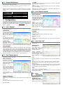
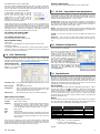
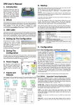
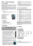
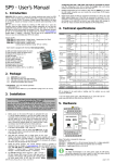
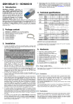
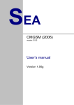
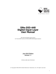
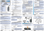
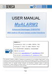
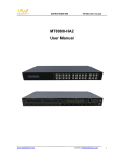
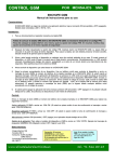
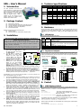
SP6 – User’s Manual 4. Technical specifications Parameter 1. Introduction You have purchased the device for remote monitoring of 9 digital inputs and remote control of 8 digital outputs using SMS text messages. The device SP6 is highly versatile and can be configured using PC program SP Init, which is supplied on CD. The program SP Init requires Windows 98, Windows 2000, Windows XP or Windows Vista. 2. Package Content 1pc 1pc 1pc 1pc 1pc SP6 module for DIN rails Antenna (product no. GSM-ANT12, with SMA connector) CD with configuration tool SP Init and documentation USB cable, type A-B (for configuration) Printed documentation SP6 BOX has different base device and antenna: 1pc SP6 BOX module 1pc Antenna (product no. GSM-ANT01S, magnetic, 5dB) 3. Installation Dimensions Power supply Logical inputs DC any polarity Logical outputs DC, AC Temperature 5.1 GSM Green Disabled PIN usage is useful when making first tests with SP6 device. For real application you can use SIM PIN protection, but you need to configure the SP6 device first (using SP Init). SND RCV ERR Yellow Yellow Red 4. d VCC ICC |VIN| 5. 6. 7. 8. 9. 10. Install software SP Init from the provided CD to your computer PC. Insert CD into your computer and wait until the introductory screen pops up. In the menu select installation software SP Init and follow the wizard instructions. Then select installation of USB driver (on the entry screen) and install it. At the final page of installer, before click on button [Finish], make sure than checkbox “Launch the CP210x VCP Driver installer” is checked! The driver creates a new virtual serial port on your PC, you can check this by clicking on Control panels System Hardware Device Manager COM and LPT ports. Connect your PC with the SP6 using the supplied USB cable. Launch software SP Init (Start Programs SEA SP Init SP Init). Read configuration from SP6 by clicking button [Read] in bottom left corner of main window. Enter correct PIN for your SIM card (panel “General”). On tab “User List” enter your phone number to and your name instead of user Smith. Click button [Save] in the bottom part of the screen. Allow a while for the program to locate the device and wait until the configuration is saved. Now disconnect USB cable. Yellow LED RCV indicates a SMS text message is received and processed. Yellow LED SND on the right hand side of the device indicates a SMS text message is being sent. Connector JP1 is used to connect special service module SM2, which may display states of the SP6 device for diagnostic. Inputs (signals to SP6) are supplied to connector JP3 and outputs (signals from SP6) are connected to connector JP4. Recommended connection of these signals can be seen in chapter “Inputs and outputs”. If the status of any input is changed, the device sends a SMS text message to your mobile in the form “Input1 is on” (depends on configuration). SP6 – User’s Manual mm mm 85 8+1 12 30 mm V DC A V <4 4 V 8 0,1 VCC = 12V 30 0,4 8 |VIN| IIN VOUT IOUT tA VIN = 12V 5 8 mA V mA °C 50 100 +55 -20 5.2 MEANING SP6 status Normally one short blinks. GSM network status blink 1:1 … SP6 starting up blink shortly 1 per 3 seconds … SP6 is fully operational in GSM network Sending SMS or outgoing voice call Receiving SMS or incoming data connection Error. Use the program SP Init to find the problem. Inputs and outputs Inputs (signals to SP6) are connected to terminal JP3 and outputs (signals from SP6) are connected to terminal JP4. See the diagrams below for connection of these signals. Input PWR WATCH (JP5) can be used as 9th input. This input is labeled PW in SP Init configuration program. C I I I I 5 5 6 7 8 6 7 8 9 6 2 3 8 9 C O O O O 5 5 6 7 8 10 DIn 6 1 2 3 6 7 8 9 10 DOut 10 DIn 1 7 4 7 8 9 10 5 DOut 4 + 5 1 C I I I I 1 1 2 3 4 2 3 4 5 C O O O O 1 1 2 3 4 SP6 - Internal Output Circuits + SP6 - Internal Input Circuits DIn1-4 or DIn5-8 DOut1-4 Max 60V DC, 100mA 8 … 30V DC C 1 2 3 4 DIn1-4 DIn5-8 C 1 2 3 4 3k9 DOut1 Congratulations, you set up device SP6 successfully. To use more functions you have to install software SP Init, see below. Unit LED diodes Insert the active SIM card (= at least one call was made) to any mobile telephone and turn off the requirement of setting the PIN. Usually this option can be found in the mobile phone menu “Setting the telephone protection” or “Setup -> Security -> PIN control”. 3. MAX. 105 60 Front panel contains indication LED diodes. Green 2. TYP. On the front panel of SP6 are located LED diodes, which indicate SP6 states and connectors for connecting digital inputs (Din1 – DIn8), digital input power watch (PWR WATCH JP5), outputs (DOut1 – DOut8), power supply (POWER JP6) and USB (JP7) COLOR First of all put the SIM card into POWER USB JP6 JP7 the SIM card reader and connect the GSM antenna. USB The SP6 device is supplied from 8 V ... 30 V DC power supply. SIM Card J7 Connect the power supply into JP8 SP6 Holder connector JP6 in the upper left GSM STA J4 J2 corner of the device. The polarity is ERR RCV J5 SND J6 J3 shown in the figure on the right. LED STA (status) on the right starts DIn DOut flashing with 2 short subsequent flashes (●● ●●). When flashing changes to 1 short flash (● ●), the PWR LOGICAL PRG SM2 LOGICAL device is ready for operation. Red WATCH INPUTS KAB OUTPUTS JP5 JP3 JP2 JP1 JP4 LED ERR changing its status to on during startup if an error occurred. (Check that PIN was specified correctly in the SP Init configuration program and that the antenna is connected. More information about errors you can find in software SP Init, card Monitoring). Send a SMS text message from your mobile in the form 1234 STATE to the telephone number of the SP6 device. The device will respond with a message describing its status “SP6: Input1=Off, Input2=Off, … , signal=58%”. MIN. 5. Hardware STA 1. Conditions w h SP6 is designed to be used inside a building only! LED Before inserting the SIM card into the SP6 device, it is necessary to disable usage of the “PIN code”! Symbol Width Height (without antenna) Depth Voltage DC Current Count Voltage log. H Voltage log. L Current Count Voltage Current Operational DIn1 DIn5 1k DIn2 DIn6 1k DIn3 DIn7 1k DIn4 DIn8 1k 3k9 DOut2 3k9 DOut3 DOut4 SP6 3k9 SP6 6. Control 6.1 SMS Message control SP6 is controlled via SMS messages of GSM network. Command SMS messages are in form: <PASSWORD> <COMMAND> [<RETURN COMMAND >] Example: 1234 STATE 1234 OUTPUT1 ON … SP6 returns a SMS containing status … SP6 output1 will be switched on. Confirmation SMS will be returned 1234 OUTPUT8 PULSE NOBACK … SP6 pulse on output8 will be generated. No confirmation message will be send It’s possible to write more commands into one command SMS. For higher readability separate commands by semicolon “;” inside command use “=”. 1234 OUTPUT1=ON; OUTPUT2=ON; OUTPUT5=PULSE; Names of inputs and outputs are user definable by SP Init program. Command SMS may look like this: 1234 GATE=OPEN; HEATING=ON; LAMP=BLINK 1 6.2 Status SMS Message Whenever command SMS contains valid password, SP6 always returns status SMS. Status SMS contains following information: <Device Name>: <DigInput1>=<DigInput1Status> <DigInput2>=<Dig Input2Status>...<DigOutput1>=<DigOutput1Status><DigOutput2>= <DigOutput1Status>...<GSM Signal Level> Status SMS message contains information only about selected inputs and outputs. Selection is done in configuration program SP Init by checking the appropriate checkbox. SP6 Status SMS Example Device SP6: Input1=on Input2=off Output1=on Signal=58% Explanation Device Name (user configurable) Logical Input 1 is on Logical Input 2 is off Logical Output 1 is on (closed) GSM Signal level in % For complete local and remote configuration and monitoring of device SP6 is used program SP Init. Configuration/monitoring can be local via USB cable or remote via GSM data connection (CSD). Note: The actual version of SP Init program can be downloaded free of charge from the website www.seapraha.cz (English pages Support GSM-SP6). Card “General” On this card, you can setup PIN code of SIM card, name of station, start-up device event and internal inputs. Initialization Enter 4 to 8 digit PIN code of the SIM card which is inserted in the SP6 device. (Leave PIN field free when usage of the PIN code on the SIM card is disabled) The “name station” identifies the SP6 device. This text is places at the begining of every sent SMS message. Special actions Use button “Actions after turning device on” to specify the text of SMS messages or voice calls which the SP6 device sends on startup (see chapter Inputs Events). Internal inputs The section “Internal Inputs“ is intended for SP6 BOX device only. Changes in this section will have no effect on other variants of SP6 devices. BOX variant contains two internal logical inputs. The first one is “BOX POWER WATCH” (PWB). This input is active whenever main power 230VAC for the BOX is functional. The second is “BATTERY LOW” (BAT), which is active as long as battery is OK. If the device has no main power and battery is near to discharge, this input goes to state inactive (L). Structure of this section is the same as for inputs on page “Digital Inputs”. 7.2 Actions (SMS or voice calls) to be done whenever the transition of input signal occurs. (see chapter „Inputs Events“). Negate In case this checkbox is checked, the meaning of state L (non active) and state H (active) are exchanged. Digital inputs are connected to terminal JP3 – Digital inputs. Digital input PW is connected to terminal JP5 – PWR WATCH. 7.3 Card “Digital Outputs” On this card, you can set up configuration for digital outputs of device SP6. 7. Configuration 7.1 Actions Card “Digital Inputs” On this card, you can set configuration of all digital inputs of SP6 device. (These inputs has only two states: YES – NO) Text in messages Input Name, State L, State H These fields contain names of inputs and and their possible states, which are listed in the status SMS message. Example: When we assign Input as input1, State L as off and State H as on, the part of SMS status message concerning input1 will look like this “input1=on”. Mention in state SMS Text in messages Output Name, State L, State H These fields contains names of outputs and their states, which are listed in the status SMS message and are used in command messages. Example: When we assign Output as output1, State L as off and State H as on, the part of SMS status message concerning output1 will look like this “output1=on”. Mention in state SMS If this checkbox is checked, the output is listed in SMS status message. Impulses Command to begin Command in command message, which begin pulse on output. Duration (h:m:s) Pulse duration on output. Negate If is this checkbox checked, meaning of state L (non active) and state H (active) is exchanged. 7.4 Card “User List” Device SP6 has one central user list. For any action a user is chosen from this central user list. Existing Users Phone number User phone number. This phone number is used for sending SMS messages or voice calls for this user. Attention: Authorization of incoming messages does not depend on the phone number. The phone number is used only for sending SMS (or voice call)! Name User name. This area is not used by SP6 device. It is for your better orientation in list. Code User code. This code is used for authorization incoming command messages. Received SMS are executed only if contains “code” of some user in your user list. Message prefix Text, which is added in front of SMS message for this user. It is used for sending messages e.g. at e-mail. This message is sending on special phone number (e.g. 4616) and first in message is e-mail address. Lists Users who get copy of all STATUS responses Choose users, to whom copy of status massage is sent whenever any status message is about to send. If this checkbox is checked, the status of this input is listed in the status SMS message. 7.5 Change notifications On this card are placed special advanced functions. Actions executed on transitions of the input and delays between transition and action. Numbered events Transition L=>H, Transition H=>L Delay (h:m:s) How long new state must be stable before action is executed. SP6 – User’s Manual Card “Advanced” “Numbered events” can change acting of digital inputs. The SP6 device can create a BUS 2 and STROBE signal from some of digital inputs. One input is changed to STROBE signal with green mark (see picture). When rising edge on this input is detected, the SP6 reads state on inputs with yellow mark as from bus. This number is considered to binary encoded event number and you can choose actions to every number independently. In this example 4 digital inputs are reserved (example right). Inputs from DIn1 to DIn3 are used as a bus and may generate event with number from 0 to 7. Input DIn4 is used as STROBE signal. Functions of other inputs are unchanged. You can use 7 inputs for, so 128 events may be generated at maximum. Typical usage is when the error numbers are sent as a code. This decreases the number of signals needed for communication with e. g. PLC. The signals with a code are called “data” signals. When these signals are valid, they are strobe by a signal called “data valid”. On a rising edge of this signal, the “data signals” are evaluated and adequate event is generated. Any combination of input “data” signal is an independent event which can send SMS and make a voice call On problem with sending SMSs How many attempts are made to send SMS. On problem with Voice call How many attempts are made to make voice call. Expert modem setting Auxiliary digital inputs Here is shown state of auxiliary digital inputs used, only for BOX variant. 7.7 SP Init – Important Terms Explanation PIN (Personal Identification Number – usually four digits number) Only persons with knowledge of PIN can operate a SIM card (in case the PIN usage on a SIM card was activated). Usage of the PIN can be deactivated. Insert the SIM card to your mobile phone and follow the instruction in the mobile phone manual. (Usually the PIN usage can be deactivated in Menu -> Security -> PIN ACCESS CODE – Password for SMS commands, configuration and monitoring of SP6. SP6 accepts only SMS with a valid access code. The password is requested also for connection of SP6 with PC (via USB cable or remotely via data connection of GSM network). Factory setting of access code is „1234“. EVENT = level change in case of logical input. SP6 can reacts on EVENTS by several ACTIONS if was setup this way. SP6 can send SMS messages on selected phone numbers and to make voice calls on selected phone numbers. ACTION = one voice call or one SMS to one user. Any EVENT can contain several ACTIONS. USER LIST = List of all users and their phone numbers which are used for ACTIONS. User names are used only for better clarity. SP6 does not use them any way. Service centre Leave empty. It is for advanced users, which have their own Service Center. Initialization commands AT commands, which sends the SP6 device on startup to GSM modem. Attention! Commands in this area can make device inoperable. Insert the commands only following counsel with device manufacturer! 7.6 Card “Monitoring” Program SP Init enables to watch status of inputs and outputs on PC monitor in tab “Monitoring”. Monitoring can be local via USB cable or remote via GSM data connection. It’s possible to switch on or off digital outputs by clicking on pushbutton [Change] or [Pulse]. It helps to check function of external circuitry. Operational status The SP6 operational status is displayed and permanently refreshed in this window. 7.8 Remote Configuration Remote configuration of device SP6 can be made via GSM data connection (CSD) in the same manner as via USB cable. Connect to your PC GSM modem. The modem has to be connected to serial port of your computer or driver for this modem has to create a virtual one. Start the program SP Init. Before dialing data connection we recommend to create whole configuration for your SP6 device off-line. Select menu [Options] and enter phone number for data connection with SP6 and click [OK]. Select COM port of your GSM modem and push button [Connect]. Data connection will be set up and you may be write configuration by button [Write]. After finishing configuration, close the data connection by pushing button [Disconnect]. 7.9 Automation state Device SP6 is basically a machine with state, i.e. Initialization, Error, Ready, Signal strength GSM signal quality in percent. Configuration State of configuration (basic and main). When is some area “Error”, in the SP6 device miss this configuration. For right function of device must be every area “OK”. GSM operator Name of GSM operator, where is the SP6 device logged in. Digital inputs and outputs Here is shown state of digital inputs and outputs. Terminal Name of input or output Unfiltered Measured values on inputs or outputs device. Measured values on SP6 inputs are filtered to remove bounces and to achieve requested delays. You can find real value of an input in this field. It is useful especially if delay for an input is longer, e.g. 1 hour. Name Name of input Value Measured value Age Values are not monitored continuously. Depending on the load of PC processor, delay between sample in SP6 and in SP Init can be up to 20 second. In this field is possible to see, how “old” is the measured value. If any of outputs is selected, in the part of card are shown buttons to change state of the output or generate pulse on the output. These functions are useful, when testing the external devices connected to the SP6 device. Delay between click on the button and actual change on the output can be up to 20 second. Inputs Events SP6 can be set up to inform about events (=changes) on its logical. SP6 sends information via SMS message or makes a voice call. By the SP Init program is possible to set several actions for each event specifying the phone number – user who will receive a SMS message and who will be called. A various SMS can be sent to and a voice call can be make to more phone numbers from the list. The order of SMS and voice calls depends on a list of actions for each action. Voice call rises the probability the user will not miss received SMS message. Event creating First of all the Event has to be created in the configuration program SP Init. Click by a mouse on the symbol of a key . By pushbutton [+ ADD] select requested action of SP6 (SMS or voice call), write the text of SMS which has to be sent or insert the sequence of DTMF numbers in case of a voice call. Now select a user and add him to a list of users for this event by a click on an arrow [>>]. Please check carefully the number of users for an event. If case the number of users is zero nothing will happen (no SMS will be send). Macros You can use macros in the text of message sent by the SP6 device. It is possible to insert name and state of digital inputs and outputs, name station and GSM signal level. These macros are replaced before sending SMS by actual value. Macro [DINx NAME] [DINx VALUE] [DOUTx NAME] [DOUTx VALUE] [SIGNAL] [STATION] Meaning Name of digital input State of digital input Name of digital output State of digital output GSM signal quality in % Name of station Example of replacement input1 on output8 Off 68% SP6 Char x stands for: 1 to 8 for DINx … as number of digital input 9 for DINx … as PWR WATCH input 1 to 8 for DOUTx … as number of digital output Example: SP6 – User’s Manual 3 SMS in configuration: Alarm. [DIN1 NAME]=[DIN1 signal=[SIGNAL] VALUE], [DIN5 NAME]=[DIN5 VALUE], SMS delivered to user: Office: Alarm. Details: door=open, safe=ok, signal=68% 8. SP6 BOX BOXPWR board contains two mutually insulated power supplies 12VDC working with common transformer from 230V AC power input. External power supply is only the rectifier + capacitor and produces voltage for external circuits of input optocouplers, the connector is blue screw terminals I/O PWR. This power supply is there to be connected with external wires with input or output SP6 signals. Main power supply for SP6 has backup battery 12V/1.2Ah and provides power on after mains fails – PWR connector internal connection type. THIS IS INTERNAL POWER SUPPLY FOR SP6 ONLY AND NO CONNECTION WITH EXTERNAL CABLES IS ALLOWED (DUE TO NOISE SEPARATION REASONS)!!! 9. Frequently Asked Questions 1. What is necessary to use SP6 successfully? SIM card capable to send and receive SMS messages from standard mobile phone and voice / data call incoming and outgoing as well. Please test all these functions in your mobile phone. It’s important to solve all possible problems before using SIM card in SP6. Contact your mobile operator if necessary. Good quality GSM signal in area of installation of SP6 (at least 2 or 3 bars on your mobile phone). If there is a problem with GSM signal quality, try to use another type of external antenna, which can be placed in proper place with better GSM signal and which is connected to SP6 with several meters long coax cable with SMA connector. Sufficient Credit (in case of prepaid SIM card) Cancel all phone calls redirection for a SIM card in SP6 2. What is a phone number of SCA (SCA = Service Center Address) of my mobile operator? (You might deal with this, when it’s not possible to send SMS form your SIM card….) Contact your mobile operator for this information. 3. I tested SP6 with my own SIM card. Now I cannot find SMS messages formerly stored on my SIM card. SMS from your SIM card were processed by SP6 and then deleted. In SP6 any received SMS is deleted just after being analyzed and executed 4. Where can I find more information? See the website www.seapraha.cz (English pages->Support->GSM-SP6). 10. Warranty General warranty period is 12 months after purchase, when eventual malfunction device will be repaired free of charge in SEA company while shipping to SEA is paid by customer and SEA pays for shipping back to customer. For SW there is 24 months warranty under following conditions: Both CPU and PC software is sold “as is”. The software was created by the best software engineers in SEA and was carefully tested both in SEA and also by SEA customers using GSM applications products made in SEA. In spite of making all possible to get error free software it can happen, that the software in CPU or PC programming SW or their mutual interaction has some error under some specific conditions. If such error is found and the description of the problem including configuration file is sent by E-mail to SEA ltd., the error is removed free of charge and SEA will send new SW by E-mail to customer. Green LED signalizes, that power 230V AC is present, that switch power supply EVER to ON state. Pressing OFF or ON pushbuttons has NO effect. SEA ltd. has NO RESPONSIBILITY for any damage, lost, costs and any other problems direct or inducted, caused by such SW error, by eventual device malfunction from any reason or by undelivered SMS from the device. (Version 1.23; 2008-09-18) If 230VAC power is not present, the power supply can be switched ON with ON pushbutton and switched OFF with OFF pushbutton. There is no signalization in this case at BOXPWR board, use LEDs at SP6 to recognize power status. If the battery is discharged, the power supply will go automatically OFF. There is about 20 sec delay after low voltage is detected and the signal is given to SP6, that gives SP6 to send SMS about low power & switching OFF. Connect 230VAC power to gray screw terminals, it may be L and N wire in 230/400V system or L1, L2 wires in 120/230V AC systems. Connect also ground – protection earth to any of 4 green screws terminals. The other green ground terminals might be used for shielding connection, if shielded wires are used for signals to and from SP6. Flat 8 pole cable between SP6 and BOXPWR transfer the signals AC POWER ON and LOW BATTERY to SP6 and so connection “POWER WATCH” terminals at SP6 is not necessary and this input might be used as general purpose 9th input with future SW versions… If you need to activate inputs from dry contacts, connect common terminal of SP6 inputs with negative terminal I/O PWR and the contact connect between corresponding input terminal and positive terminal of I/O PWR. Note, that optocouplers in SP6 are both polarity type and so you can reverse the polarity, if needed. You can use only I/O PWR power supply for optocouplers external circuits. Outputs are equipped with photo MOS relays that can switch AC or DC of any polarity. If you connect some relays or contactors on them, you can do it with long wires, but these must stay insulated from power supply for SP6, otherwise the device may be unreliable due to noise coming into these wires. You can use only I/O PWR power supply for relay coils. If you need to use for input optocouplers or output relays the power supply with backup, that powers SP6 electronics, you must install additional DC/DC converter into SP6 BOX to get separated power. DONOT USE DIRECT CONNECTION, OTHERWISE NOISE PROBLEMS MAY OCCUR! SP6 – User’s Manual 4