1
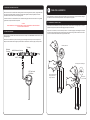
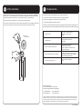
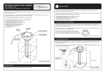
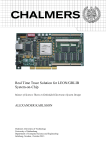
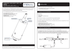
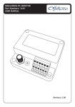
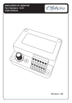
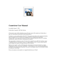
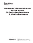
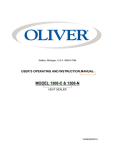
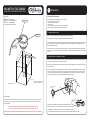
VOLUMETRIC FUEL SENDER
1
INSTALLATION AND OPERATING INSTRUCTIONS
INSTALLATION
Choosing the Sender location
Part Numbers:
3271-xxxx SAE 5 Bolt Mounting
3271N-xxxx 1.5” NPT Thread Mount
3271T-xxxx 1.25” BSP Mounting
Choose a location on the top surface of the fuel tank that
• Is over the deepest part of the tank
• is clear of any internal baffles
• is flat and level
• is within reach of an inspection hatch to facilitate mounting
• Allows installation of the Fuel Sender without bending it.
Rotary Switch
(xxxx is probe length in millimeters)
1.1 SENDER MOUNTING OPTIONS
LED Indicator
The 3271 Sender is available with three different standard mounting options:
The original 3271 fuel sender is mounted using a standard 5 bolt SAE mount.
To mark the SAE 5 bolt holes place the cork mounting gasket at the desired location and mark the central hole and
the 5 mounting bolt holes using a pencil through the holes in the gasket. Please note that the gasket holes are
NOT arranged symmetrically.
Magnet Area
The 3271N fuel sender is mounted using a standard American 1 ½”NPT (Tapered National Pipe Thread) threaded
mount. The 3271T fuel sender is mounted using a standard 1¼” BSP (British Standard Pipe) threaded mount with O
ring seal.
1.2 MEASURING AND CUTTING SENDER TO LENGTH
Carefully measure the depth of the tank vertically from the top surface of the tank through the probe hole to the
level of the fuel pickup tube near the bottom of the tank.
Measure from the underside of the sender body and mark the required probe length on the probe outer tube using
an indelible marker.
Using a sharp hacksaw cut through the probes outer tube and inner rod to length TOGETHER. Do NOT use a pipe
cutter or an angle grinder which could close the outer tube and restrict fuel flow into the tube. Ensure that the
cut is clean and deburred inside the tube as any swaff traped inside the tube could the affect the reading. This
may require the dismantling, cleaing and reasembaling of the tube if necessary.
Fuel tank/container
Make certain sender and fuel
pickup are at the same level.
Support both ends of
Fuel Sender
SAFETY WARNING
Fuel sender should only be installed by a person competent and experienced in working with electrical systems
and fuel tanks. All work involving fuel tanks should be performed with extreme care due to the possibility of
igniting fuel fumes.
THE TANK MUST BE EMPTY, DRY, AND PURGED OF ALL FUMES BEFORE COMMENCING WORK.
IF YOU FAIL TO DO THIS YOU ARE EXPOSING YOURSELF TO A POTENTIALLY FATAL HAZARD.
Before beginning work the battery should be disconnected to avoid the risk of a short circuit, a fire or explosion.
Install the new black plastic insulator supplied in the bag about 5mm
from the end of the inner rod so it that tyhe rod cannot touch the outer tube.
It is ESSENTIAL to ensure that the fuel can flow into the tube easily and freely.
The probe CANNOT measure the fuel level unless the fuel has easy access INTO the probe tube.
1.3 MOUNTING THE SENDER TO THE TANK
2
Either mount the 3271 5 bolt SAE sender and the gasket to the tank using 5mm bolts, washers, spring washers and
nuts. Apply some suitable sealant to the washers and bolt heads. Tighten the bolts progressively around the
circumference of the sender to ensure a liquid tight seal.
Or mount the 3271N or T threaded sender to it’s threaded mounting point and screw down until the O ring makes
a good seal or the taper thread is firmly seated.
CAUTION
ALWAYS OBSERVE THE FUEL TANK DURING INITIAL FILLING AND OPERATION TO ENSURE THERE ARE
NO LEAKS AT THE SENDER MOUNT.
1.4 WIRING AND NETWORK
The plug on the fuel sender cable should be mounted into a T adaptor on the NMEA2000® network as shown in the
following diagram.
TANK LEVEL CALIBRATION
The sender MUST be calibrated to the empty tank AND to the full tank before it can give an accurate reading. It
will NOT be accurate until both steps are done. This is a simple two step process.
2.1 CALIBRATING TO THE EMPTY TANK
The sender must be calibrated to the empty tank value either with the sender in the empty tank, or if it is not
possible to empty the tank, with the sender hanging vertically next to the tank.
Apply power to the network, turn the small rotary switch to “E” and then applying a small magnet to the top of
the sender at the marked point. When the sender detects the magnet it will light the blue LED for 2.5 seconds
and will then measure and remember the empty calibration value.
Ensure that it is mated securely and the retaining ring has been tightened correctly to ensure the junction is
waterproof. Note that this cable length may be extended to a maximum of 6 metres by using micro drop cables.
Set Rotary Dial to ‘E’
To display
F01
ABCDE
NMEA2000 Network Backbone
23456
789
3804 Male
Terminator
3802 T - Adaptor
+12v
3271 Fuel Sender
250-3000mm
Set empty level with a Magnet
Do not touch the metal
casing of the device
during calibration.
LED stays on
for 2.5 seconds
2.2 CALIBRATING TO THE FULL TANK
3
The sender must then be calibrated to the full tank value either with the sender in the full tank, or if it is not
possible to fill the tank, with the sender hanging vertically in a tube of fuel to the desired full level next to the
tank.
Apply power to the network, turn the small rotary switch to “F” and then applying a small magnet to the top of
the sender at the marked point. When the sender detects the magnet it will light the blue LED for 2.5 seconds
and will then measure and remember the full calibration value.
TANK VOLUME CALIBRATION
The 3271 Volumetric Fuel sender can be set to either transmit the remaining tank LEVEL as a percentage or the
remaining tank VOLUME as a percentage.
The 3271 can be user or factory programmed with up to 100 points of volumetric information and to transmit the
remaining fuel VOLUME percentage if the user chooses. This can then be shown on any NMEA2000 Fuel Level
Display.
The user can do this volume calibration using the 3340 Colour Multifunction Display or it can be done by Offshore
Systems from tank drawings or from a 3D CAD model.
Set Rotary Dial to ‘F’
789
When the unit is transmitting the tank VOLUME the blue LED will give a DOUBLE FLASH every 2.5 seconds.
ABCDE
3.1 SELECTING VOLUME OR LEVEL MODE
23456
F01
When the unit is transmitting the tank LEVEL the blue LED will give a SINGLE flash every 2.5 seconds.
The unit can be switched from LEVEL to VOLUME mode very easily. By setting the rotary switch to “C” and
applying the magnet as before, the unit will transmit the tank LEVEL. This will show a single flash.
By setting the rotary switch to “D” and applying the magnet as before the unit will transmit the tank VOLUME.
This will show a double flash.
Set full level with a Magnet
Do not touch the metal
casing of the device
during calibration.
Do not forget to set the rotary switch to the tank instance or number after doing this (see section 4). If the unit
has NOT been programmed with tank volume information then setting it to transmit volume will send the normal
tank level information for safety.
3.2 WATER IN FUEL DETECTION
The fuel sender will detect the presence of water in the fuel and alert the user to the problem. If the probe tube
is in contact with water the sender will cease to transmit the actual fuel level and send tank empty and tank full
alternatively to attract the users attention to the fuel gauge associated with the contaminated tank.
LED stays on
for 2.5 seconds
The user should drain the water out of the contaminated tank and refill with clean fuel. This should remove the
water from the probe tube which will then revert to transmitting the actual tank level.
In the event that the sender is still transmitting the tank empty / tank full signal this means the water contamination was severe enough to be forced into the fuel probe tube. In this case the sender will need to be demounted
from the tank and have the probe outer tube removed and cleaned internally and the probe inner cleaned.
Re-assemble and remount in the normal way.
Operation
4
5
SETTING THE INSTANCE
When the unit is installed the small rotary switch should be set to reflect the fuel tank number. The NMEA2000
standard allows for up to 16 different fuel tanks to be installed on a single network and these should be selected
by using switch positions 0 for the first tank, 1 for the second tank up to 15 for the sixteenth tank.
Once the module has been installed there is no normal operator intervention required.
The unit has a blue LED which flashes every time the sender transmits a signal. If this is not flashing it means that
the unit is not receiving power from the network or that no other device is connected to the network.
TROUBLE SHOOTING
If the sender is sending inaccurate readings then this can ONLY be due to either:
1. The fuel is not free to travel up inside the tube due to a blockage at the bottom
of the probe or a blockage of the air release hole(s) at the top of the tube.
2. The tank LEVEL calibration has been done incorrectly.
There can be no other cause than these. The principle of operation of the sender is based on simple physics and
providing the fuel has free access and the calibration has been done correctly the unit will ALWAYS read correctly.
LED does not flash
Check power is provided to network.
Check cable runs have not been
damaged.
F01
LED flashes rapidly
No display equipment connected to
receive data.
789
Fuel level alternates from 0% to 100%
Probe is shorted out, remove tube
and check for swarf and probe
insulator is fitted. Water contamination, see
“Water in Fuel Detection”.
FI have multiple tanks but only 1 is displayed
Check each rotary switch is addressed to an individual
tank instance and the display is set to receive the
corresponding tank instance. Check the display is
capable of displaying multiple tanks.
Fuel level is not reading correctly.
Carry out “Tank Level Calibration”
process.
23456
ABCDE
Set Rotary Dial
to desired instance
Offshore Systems (UK) Ltd
Unit 10 -11 Milton Business Centre, Wick Drive,
New Milton, Hampshire, BH25 6RH, United Kingdom
Tel: +44(0)1425 610022
Email: [email protected]
Fax: +44(0)1425 614794
Web: www.osukl.com
Copyright © 2013 Offshore Systems (UK) Ltd. All rights reserved.Our policy is one of continuous product improvement so product
specifications are subject to change without notice. Offshore Systems products are designed to be accurate and reliable. However,
they should be used only as aids to vessel monitoring, and not as a replacement for traditional navigation and vessel monitoring
techniques. NMEA2000® is a registered trademark of the National Marine Electronics Association.
DOC NO. 00000 Rev. 1.0