1
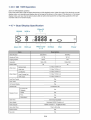
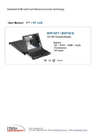
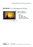
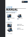
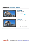
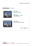
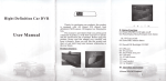
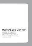
Dedicated KVM switch and rackmount screen technology r User Manual 19” LCD A ■ 1 m .. NPQ919 9U Quad Display "bill * * * ! m * Options : - DC power > R £ C€ REACH ROHS ^ |-T~E^j|""I C^DN^RA.N^f' i-Tech Company LLC TOLL FREE: (888) 483-2418 • EMAIL: [email protected] • WEB: www.iTechLCD.com J Legal Information First English printing, October 2002 Information in this document has been carefully checked for accuracy; however, no guarantee is given to the correctness of the contents. The information in this document is subject to change without notice. We are not liable for any injury or loss that results from the use of this equipment. Safety Instructions Please read all of these instructions carefully before you use the device. Save this manual for future reference. ■ ■ ■ ■ ■ ■ ■ ■ ■ ■ ■ Unplug equipment before cleaning. Don't use liquid or spray detergent; use a moist cloth. Keep equipment away from excessive humidity and heat. Preferably, keep it in an air-conditioned environment with temperatures not exceeding 40° Celsius (104° Fahrenheit). When installing, place the equipment on a sturdy, level surface to prevent it from accidentally falling and causing damage to other equipment or injury to persons nearby. When the equipment is in an open position, do not cover, block or in any way obstruct the gap between it and the power supply. Proper air convection is necessary to keep it from overheating. Arrange the equipment's power cord in such a way that others won't trip or fall over it. If you are using a power cord that didn't ship with the equipment, ensure that it is rated for the voltage and current labeled on the equipment's electrical ratings label. The voltage rating on the cord should be higher than the one listed on the equipment's ratings label. Observe all precautions and warnings attached to the equipment. If you don't intend on using the equipment for a long time, disconnect it from the power outlet to prevent being damaged by transient over-voltage. Keep all liquids away from the equipment to minimize the risk of accidental spillage. Liquid spilled on to the power supply or on other hardware may cause damage, fire or electrical shock. Only qualified service personnel should open the chassis. Opening it yourself could damage the equipment and invalidate its warranty. If any part of the equipment becomes damaged or stops functioning, have it checked by qualified service personnel. What the warranty does not cover ■ Any product, on which the serial number has been defaced, modified or removed. ■ Damage, deterioration or malfunction resulting from: D Accident, misuse, neglect, fire, water, lightning, or other acts of nature, unauthorized product modification, or failure to follow instructions supplied with the product. □ Repair or attempted repair by anyone not authorized by us. □ Any damage of the product due to shipment. □ Removal or installation of the product. □ Causes external to the product, such as electric power fluctuation or failure. □ Use of supplies or parts not meeting our specifications. □ Normal wear and tear. □ Any other causes which does not relate to a product defect. ■ Removal, installation, and set-up service charges. Regulatory Notices Federal Communications Commission (FCC) This equipment has been tested and found to comply with the limits for a Class B digital device, pursuant to Part 15 of the FCC rules. These limits are designed to provide reasonable protection against harmful interference in a residential installation. Any changes or modifications made to this equipment may void the user's authority to operate this equipment. This equipment generates, uses, and can radiate radio frequency energy and, if not installed and used in accordance with the instructions, may cause harmful interference to radio communications. However, there is no guarantee that interference will not occur in a particular installation. If this equipment does cause harmful interference to radio or television reception, which can be determined by turning the equipment off and on, the user is encouraged to try to correct the interference by one or more of the following measures: ■ Re-position or relocate the receiving antenna. ■ Increase the separation between the equipment and receiver. ■ Connect the equipment into an outlet on a circuit different from that to which the receiver is connected. Contents < Part. 1 > NPQ919 1.1 1.2 1.3 Package Content Structure Diagram & Dimension Installation P.1 P.1 P. 3 < Part. 2 > Specifications / OSD 2.1 2.2 Product Specifications On-screen Display Operation (OSD) P.4 P.6 < Part. 3 > Options 3.1 48V, 24V or 12VDC power P.7 < Part. 4 > Quad Display Connection & Operation 4.1 4.2 4.3 4.4 4.5 4.6 4.7 QD QD QD QD QD QD QD Connection ALARM Connection & Operation Remote Control Connection & Operation OSD Operation On-screen Menu VCR Operation Specification P8 P.9 P. 11 P.16 P. 17 P20 P20 < Part 1 > < 1.1 > Package Content NPQ919unit X 1 - 6ft VGA cable X 1 - Power adapter X 1 - Power cord X 1 < 1.2 > Structure Diagram Front view Power adapter Rear view 0 LCD panel © LCD OSD membrane © Quad display control membrane @ Power adapter basket RS-232 Video IN 1 r4 VCR in <o> □ Q> Alarm I/O Power cord VCR out Video Loop 1 ~4 S-Video VGA Option : DC power P.1 o Power < 1.2 > Dimension Front View 379 CD o OJ o rearing |o«-«*«-«i 463 480 UNIT: mm 1mm = 0.03937 inch Bottom View 480 § QQQQ O <Z> 440,6 Model Product Dimension (W x D x H) Packing Dimension (W x D x H) Net Weight Gross Weight NPQ919 480x68,5x399 mm 18.9x2.7x15.7 inch 583 x124 x529 mm 23x4.9x20.8 inch 9.5 kg 20.9 lbs 12.5 kg 27.5 lbs P.2 < 1.3 > Installation Step ■ Mount the display panel with M6 screw set. ■ M6 screw x 8 pcs required ( Left & right side ). M6 screw sets are not provided. Step O Fix the LCD into the rack. P.3 < Part 2 > < 2.1 > Product Specifications AJO Manufacturer 19-inch TFT color LCD Panel Size ( diagonal) 1280x1024 Display pixel ( dots x lines ) 250 Brightness (typ. ) Contrast Ratio (typ. ) 1000:1 Color 16.7 M 85/85/80/80 Viewing Angle (L/R/U/D) 5 Response Time ( ms ) 0.294 Dot pitch ( mm ) 376.32HX 301.06V Display Area ( mm ) Surface treatment Haze 25%, Hard-coating Surface hardness 3H LED Backlight Type 30,000 MTBF ( hrs ) Video Connectivity Regulatory Environmental Conditions Analog VGA Analog 0.7Vp-p Power Supply Range Auto-sensing 100 to 240VAC, 50/60Hz Power Consumption Screen display ON 25W or less Power saving mode 4W or less Power button OFF 1Wor less Safety FCC & CE certified Environmental RoHS2 & REACH compliant Operating Storage Temperature 0 to 50°C degree Humidity 20-90%, non-condensing Temperature -5 to 60°C degree Humidity 5-90%, non-condensing Shock 10G acceleration (11ms duration) Vibration 5-500Hz 1G RMS random P.4 Physical Specification Product ( W x D x H ) 480x68.5x399 mm 18.9x2.7x15.7 inch Packing ( W x D x H ) 583 x124 x529 mm 23x4.9x20.8 inch Net Weight 9.5 kgs/20.9 lbs Gross Weight 12.5 kgs/27.5 lbs DVI-D/VGA Input PC Signal 1280 x 1024 x 60 / 75Hz 1280 x960 x60Hz 1280x760x60/75Hz 1152 x864 x75Hz 1024x768x60/70/75Hz 848 x 480 x 60Hz 800 x 600 x 60 / 72 / 75Hz 720 x 400 x 70Hz 640 x 480 x 60 / 72 / 75Hz 640 x 400 x 70Hz 640 x 350 x 70Hz P.5 < 2.2 > On-screen Display Operation ( OSD ) LCD OSD Menu O Power light • Green = On Orange = Power saving Membrane Switch o Function (!) Power on / off LCD DP Display the OSD menu AV<3 > <e> Scrolls through menu options and adjusts the displayed control (To auto adjustment by pressing the button /^ for 5 seconds) Exit the OSD screen Toggle analog, digital & video connection (DVI-D and video options only) r Ver: G56SN20SSTD701 m Image Brightness [~f~1 I1 \ *\ — 1*1 |J>I Misc OSD Configuration Page ffi K3 * Adjust: ♦ * 1024x768 59.8Hz Contrast Color Temp . ^^^^^m ^^^^^ User Red Green Blue Select: ♦ + Set: ®/l=J Image: for the brightness, contrast, color temp, red, green, and blue Geometry: for the auto adjust, H position, V position, phase and clock Video: for the colour, tint, sharpness, noise reduction, DCDi and TV Setup J> Misc Audio: for volume, bass, treble, balance, AVL and mute Misc: for the language, OSD position, graphic mode, ratio, reset and timer P.6 Exit:t < Part 3 > < 3.1 > Options : DC Power 12V 24V 48V Input voltage: 12-Volt 24-Volt 48-Volt Input range: 9-18V 18-36V 36 - 75V - No load 50 mA 50 mA 50 mA - Full load 4950 mA 2450 mA 1220 mA Output voltage: 12-Volt 12-Volt 12-Volt Output current: 4.16A 4.16A 4.16A 84% 85% 85% Model Input rating Input current Output rating Efficiency P.7 < Part 4 > < 4.1 > QD Connection rP Camera 1 P Camera 2 Camera 3 DC 12V In 4=> Camera 4 0^ VCR Monitor Processor VCR(DVR) 1. VCR i n : This BNC connector is connected to video output from VCR/DVR. A pre-recorded quad screen signal from a tape can be played back through a VCR/DVR and displayed on the video output channels. Push the VCR button (#2) to switch the device to VCR Playback mode. 2. VCR o u t : This BNC connector is to be connected to the Video in from your VCR/DVR. It will only provide a quad screen video to ensure an un-interrupted video recording for all four cameras. The display video is not affected by the control panel. 3. Terminations : These impedance switches are used to provide proper termination for each camera input. These switches toggle be tween 75Q and Hi-Z impedance. Incorrect termination will degrade the quality of the video signal. All video inputs not "looped through" to another device, the corresponding switches need to be set to 75D termination position. If another device is connected to video out loop through connector set the corresponding termination switch to Hi-Z position. Any device connected to the video out loop through connectors needs to be configure to 75Q video termination. The factory default termination setting is 7 5 0 . 4. C M In, Ch2 In, Ch3 In, and Ch4 In Video IN connectors : These BNC connectors are used to connect to the video out from camera. Four cameras can be connected to these con nectors to form a quad screen in the following mapping order. 1 2 3 4 J 5. Ch1 Out, Ch2 Out, Ch3 Out, and Ch4 Out Video Loop through connectors : These connectors are used to loop video signals from each camera out to other devices. P.8 < 4.2 > QD ALARM Connection & Operation 1. ALARM I/O: This female type 9 pin D-sub connector is used for alarm sensor input and alarm output control connections. It provides Normal Open and Normal Close contacts for alarm out control. Pin Assignment for Alarm Connector (female type) PIN# PIN# PIN# 1 Sensor 1 4 Sensor 4 7 Normal Open Contact 2 Sensor 2 5 Reset In 8 Common Contact 3 Sensor 3 6 GND 9 Normal Close Contact The Alarm Hold Time can be configured from 0 second to 99 minutes through system Setup menu. 2. VCR Connection for Tape Recording Start and Stop Control : Connecting the contacts of VCR RECORD and STOP switch to the alarm output NC and NO contacts will allow you to use an ordinary VCR to record for longer period of time. Combined with alarm sensor detection, the VCR will record only when an alarm sensor is activated. m m ■'H, :: JP i \ 11 _>o / { Recorder SW Y \ O^ COM Stop SW VCR(DVR) L / \\ [fo\\v/l / \ o Stop SW Recorder SW / \ \ _l_ 4 • \COM(GNDorVCC) Alarm triggered start recording NO-^NC Recording stop V J Alarm hold duration recordmg time *. If more than one sensor have been trigged, VCR will start to record after the last trigged event. *. In order to make use of the alarm called full screen display function, the VIDEO IN connector from the VCR has to be connected to LIVE monitor connector of the device. If more than one sensor are trigged, VCR will then record all the events in full screen mode accordingly. P.9 < 4.2 > QD ALARM Connection & Operation 3 Sensor Activated Alarm The unit is equipped with 4 alarm sensor inputs. If any alarm is activated: ■ the built-in buzzer and the alarm output control relay contact will be activated. ■ the quad will switch the corresponding channel indicator LED to blinking mode. ■ a warning message depending on different models will be displayed as follows: Quad output channel (#4) LIVE output channel (#5) Alarm Alarm Blinkinj3 Alarm & Title message3 on the Full screen display of the activated channel. Also display a blinking Alarm message activate3d channel in quad sereien Above mentioned alarm can be cleared by any of the following: 1. Connecting the Alarm Reset In contact, pin #5, of the female type 9 pin D-sub connector (#8) to GND. 2. The Alarm Duration time elapses. 3. If the device is operated under Security Lock ON mode, Push Lock button for 2 seconds to disable the function then push any button in the front panel. 4 Video Loss Alarm Loss of video at any input is automatically detected by the device. The device wil ■ Activate the built-in buzzer. ■ Switch the corresponding channel indicator LED to blinking mode. ■ Display warning message on quad screen: Quad output channel (#4) Video loss ■ The warning message and the buzzer can be cleared by pushing Lock button (#2) for more than 4 seconds if the device is operated under Security lock On mode, or pushing any button on the front panel if the device is operated under Security lock OFF mode. Blinking Video Loss & Title message on the activated channel in quad screen P.10 < 4.3 > QD Remote Control Connection & Operation ALARM I/O vcr RS-232 Cable Wire P.11 < 4.3 > QD Remote Control Connection & Operation The device can be controlled via the male type 9 pin D-sub/RS-232 connector to a computer using ASCII code. 1. Pin assignment of the male type 9 pin D-sub connector: Pin Assignment for Remote Control Connector 1 2 3 4 5 0 0 0 0 0 6 o 7 o 8 o 9o 1 GND 2 RX 3 TX 4 NC 7 VCC 5 NC 8 GND 6 VCC 9 GND When a computer is used to control this device through a RS-232 port, pin 6, 7, 8, and 9 must be disconnected to prevent connecting the VCC and GND signals from the device to the computer. A RS-232 port only uses pin 1, 2, and 3 for control signal transmission. 2. A terminal or computer can be connected to the male type 9 pin D-sub connector on the real panel from it RS232 port to control this device using standard, uppercase ASCII codes. 2.1 The ASCII command codes for the quad are listed in the table below. The transmission protocol is 1200baud rate, 8 data bit, 1 start bit, 1 stop bit, and no parity. Function ASCII Command Code Quad Screen Display E CH 1 A CH2 B CH3 C CH4 D Freeze *1 EA, EB, EC, ED Auto Switching Sequence F VCR/Live G Key Lock *2 H Setup Menu *3 GH Text Select Down *4 (GH)A Text Select Up (GH)B Cursor Left (GH)C Cursor Right (GH)D Alarm Reset I P.12 < 4.3 > QD Remote Control Connection & Operation *1. In order to control the device to operate in Zoom mode, the computer has to first send command code " to switch the signal source from camera to VCR/DVR, at this time the device will automatically zoom channel 1 video from VCR/DVR to full screen. User can then input a correspond ing channel code to zoom any other specific channel. Input the corresponding channel code again to put the specific channel to freeze mode and send the code again to clear the freeze mode. Example: Input GE, (GE) B, (GE) C, and (GE) D for zooming the video signal in channel 1 to 4 from VCR/DVR. Input "A", "B", "C", "D" again to freeze the specific channel. Send command code "G" again to get back to Live input mode. *2. Computer has to send out command code "H" continuously for 2 seconds to switch the device be tween security lock ON and OFF mode. If any alarm is activated under security lock ON mode, the device has to send out command code "H" continuously for more than 4 seconds to clear the alarm. *3. Setup menu is switched ON by sending VCR/DVR and Lock button codes together. *4. Text Select and Cursor Control functions can be performed only under menu Setup mode. 2.2 Right after computer/terminal has sent out the above mentioned control command code to the device, the device will respond with following status code back to computer through RS-232 port: Status Code Quad Status EF EE Status Code Quad Status Device in Quad mode DE CH1 in Sequence mode CH1 in Freeze mode DD CH2 in Sequence mode ED CH2 in Freeze mode DB CH3 in Sequence mode EC CH1 & 2 in Freeze mode D7 CH4 in Sequence mode EB CH3 in Freeze mode CF Quad display in Sequence mode EA CH1 & 3 in Freeze mode E9 CH2 & 3 in Freeze mode E CH1 in Full screen mode E8 CH1, 2, & 3 in Freeze mode D CH2 in Full screen mode E7 CH4 in Freeze mode B CH3 in Full screen mode E6 CH1 & 4 in Freeze mode 7 CH4 in Full screen mode E5 CH2 & 4 in Freeze mode E4 CH1, 2 & 4 in Freeze mode E3 CH3 & 4 in Freeze mode XX-DF Buzzer/VCR ON E2 CH1, 3, & 4 in Freeze mode XX-7F Security lock ON E1 CH2, 3, & 4 in Freeze mode XX-3F Buzzer & Security lock ON (Stop) EO CH1, 2,3, & 4 i n Freeze mode P.13 Attach to above code < 4.3 > QD Remote Control Connection & Operation 2.3 The configuration of the status code for both normal and alarm operations: There are total 2 bytes of the status codes. Byte one, the first 8 bits, shows the current status of the operation modes that the unit is in. Byte two, the second 8 bits, shows the current status of the alarm operations of the unit. BYTE1 BYTE 2 START STOP STOP START BYTE 1: Status code for normal operation modes b7 b6 b5 b4 b3 b2 b1 bO LOCK VCR SEQU QUAD CH4 CH3 CH2 CH1 Channel Select 1110 = CH1 1101 =CH2 1011 =CH3 0111 =CH4 Display Mode 0 = Quad screen display 1 = Full Screen display Auto-sequencing mode 0 = Auto sequencing mode 1 = Quad or full screen mode VCR mode 0 = VCR operation 1 = Live operation Security Lock mode 0 = Security lock ON mode 1 = Security lock OFF mode Menu Setup mode 00 = Menu setup mode P.14 < 4.3 > QD Remote Control Connection & Operation BYTE 2: Status code for alarm operations: The first 4 bits show the sensor activated alarm status of each channel; next 4 bits show the video loss alarm status of each channel. The digit " 1 " means alarm event is detected, and "0" means no alarm event is detected. b3 - bO: Video Loss Alarm b7 - b4: Sensor Activated Alarm b7 b6 b5 b4 b3 b2 b1 bO Ch^4 CH3 CH2 CH1 CH4 CH3 CH2 CH1 Sensor activated Alarm 0001 =CH1 activated 0010 = CH2 activated 0100 = CH3 activated 1000 = CH4 activated Video Loss Alarm 0001 =CH1 activated 0010 = CH2 activated 0100 = CH3 activated 1000 = CH4 activated P.15 < 4.4 > QD OSD Operation © (f) o o d) VCR o Quad Display Control o o o ffi SEQ o a E V A < 1—Selup—1 © @ o B a > © (T) Lock: Security locks out button. Push this button for 2 seconds to enable control panel lock out function. Push this button again for 2 seconds to disable the function. (2) VCR: Push this button to enter into VCR Playback/Zoom operation. In this mode, the output video is displaying the video signal from VCR. When operated in Full Screen display mode, push select buttons (#5) to zoom any specific camera signal pre-recorded on the tape in quad format. Push the select button (#5) again to freeze the expanded picture on the screen. VCR button (#2) Quad button (#4) CH Select button (#5) ON ON OFF ON OFF Push Once Call up specific quadrant from tape in full screen mode ON OFF Push Twice Freeze specific quadrant from tape in full screen mode OFF X X Exit VCR operation and back to normal operation mode Function Display quad video signal from VCR tape #1, #2 Setup buttons: Push these two buttons simultaneously to get into Menu Setup mode and display page 1 of system setup menu. Push these two buttons simultaneously again to display page 2 of the setup menu. Use page 1 to program time/date and camera title and page 2 to configure alarm operations. Under menu setup mode, Channel Select buttons (#5) are used for cursor control and text selection to program the setup menu. Push the setup but tons simultaneously again to save the setting. Push the setup buttons fourth time to get back to ordinary operation mode. CH Select buttons (#5) Setup buttons (#1, #2) Function UP, DOWN < , > Push once Page 1 menu for time / date / title programming Text Selection Cursor Control Push twice Page 2 menu for alarm configuration Text Selection Cursor Control Push the third time Save the settings Yes / No Push the fourth time Exit setup mode, back to normal (5) SEQ.: Push this button to enable full page auto sequencing mode. Push this button again to disable it. (4) Q J : Push this button to switch between Quad/ Full Screen display mode. buttons: When operated in Quad mode, these buttons are used to freeze any specific camera by pushing the corresponding button. When operated in Full Screen display mode, these buttons are used to select specific camera to be displayed in full screen. Quad button (#4) Channel Select buttons (#5) Function ON ON Freeze specific camera video in Quad screen mode OFF ON Call up specific camera video in full screen mode These buttons are also used as cursor control and text select keys under Setup menu mode. P.16 < 4.5 > QD On-screen Menu Right after the unit is turned on, The monitor will display the last setting on the Setup Menu. 1. Page 1 of the Setup Menu - Display Setting Push Setup buttons (#1, #2) simultaneously to display the Setup Menu on the screen. There are total two pages in the Setup Menu. Page 1 is used to program TIME, DATE, and camera TITLE. Page 2 is used to program Alarm Operations. Under this mode, channel selection buttons (#5) on the front panel are used for cursor control and text selection. Use the cursor control buttons "<" and ">" to move the cursor to the location as desired to program, and use the text select but tons " ^ " and " ^ " to choose the right alphanumeric character to program. Page 1: Setting the TIME, DATE, TITLE, and DWELL time: CH TITLE QUAD 1 CH 1 2 CH2 3 CH3 4 CH4 LIVE VIDEO FREEZE VIDEO OUT: TITLE: TIME: 23: 10: 10 DATE: 12-25-2003 DWELL LIVE ON ON ON TIME 03S 03 S 03 S 03 S 03 S ON QUAD ON ON ON 1.1 TITLE setup: The Title menu permits the setup of separate titles for each video channel. 8 characters may be entered for each video channel. The available alphanumeric characters are: 0, 1,2, 3,4,5,6, 7, 8, 9, A, B, C, D, X, Y, Z, . , : , - , / , < , > , ^ , ^ - , space , 1.2 DWELL Time setup: The Dwell time menu permits setting the dwell time for all cameras and the Quad Screen on the LIVE output channel. The menu shows a table of all cameras and associated dwell time. Dwell time can be programmed by setting a number between 00 to 99 for each channel in the menu. ■ 01 through 99: Adds the camera input to the auto switching SEQUENCE, with the corresponding dwell time in seconds. ■ 00: Skips the camera input in the auto switching SEQUENCE. 1.3 TIME/DATE setup: Time and date information can be displayed on the video output channel through both LIVE and QUAD connector. Bot tom of page 1 is used to set the values of time and date and also to enable or disable the display at each output channel. The date and time will display in the "MM-DD-YYYY HH:MM:SS" format for NTSC model and "DD-MM-YYYY HH:MM:SS" format for PAL model. 1.4 TITLE/TIME/DATE disable and enable on LIVE and QUAD video output channel: The Title/Time/Date display on each output channel can be enabled or disabled by setting ON or OFF in the correspond ing entry. P.17 < 4.5 > QD On-screen Menu 2 Page 2 of the setup menu- Alarm Setting Push Setup buttons (#1, #2) simultaneously and push (#1) button again to display page 2 of the setup menu on the screen. This Alarm Setting menu is used to set the desired alarm configuration like sensor type, sensor sensitivity, alarm hold duration, and buzzer. ALARM SETTING CH SENSOR TYPE 1 OPEN NO 2 OPEN NO 3 OPEN NO 4 OPEN NO SENSITIVITY: DURATION: BUZZER: V-LOSS ALARM: V-LOSS RELAY: STATUS ON ON ON ON 0.3 S 30 S ON ON OFF 2.1 Sensor Type: The machine will first detect the type of the sensor connected to the corresponding channel. The result will be displayed in the first column following each channel number. They can be on either OPEN or CLOSE. The menu then allows user to enter a desired type of the sensor for each channel in next column. NO means Normally Open. NC means Normally Close. Then the menu will allow user to enable or disable sensor input for each channel in the next column. ON will enable the contact to detect the alarm status from the input. OFF will ignore the sensor input and disable the alarm detection from the input. Last column on this part of the menu shows the result of the actually detected sensor type and the desired configuration. If the setup type of the sensor is different from the actually connected type of sensor, a blinking "?" message will display. In this case, the buzzer will be activated when you exit the setup operation. 2.2 Alarm Sensitivity: Alarm sensitivity can be programmed to different extent by setting the period of the trigged pulse detected by the sensor. The available settings are 100ms, 200ms, 300ms, 400ms, 500ms, 600ms, 700ms, and 800ms. 2.3 Alarm Hold Duration: The alarm hold duration can be set from 00 second to 59 minutes. The duration can be set to non-stop by choosing " » " . In this mode, the activated alarm can only be reset by connecting the alarm reset contact to ground. 2.4 Buzzer: The device has a build-in buzzer to signal a detected alarm through sound. User can choose to disable the buzzer by setting it to OFF. 2.5 V-Loss Alarm: This entry is used to enable or disable the video loss alarm. The device automatically detects loss of video at any input if this entry is set to ON. User can choose to disable this feature by setting it to OFF for applications like video conferenc ing or others that will need constant video source switching. 2.6 V-Loss Relay Control: The device is equipped with an alarm controlled relay, which can be activated by both sensor trigged alarm and video loss alarm. This entry allows user to disable the relay activation from a loss of video in any camera input. 3 Save the settings and exit Setup Menu mode Push (#1) button again will allow you to save the settings and go back to the normal operation mode and show a quad display on the screen. P.18 < 4.5 > QD On-screen Menu 4: The setup menu can be reset to factory setting by pushing the Setup buttons (#1, #2) and power on the quad simultaneously. The factory setting is as follows: CH TITLE QUAD 1 CH 1 2 CH2 3 CH3 4 CH4 LIVE VIDEO FREEZE VIDEO OUT: TITLE: TIME: 2 3 : 10: 10 DATE: 1 2 - 2 5 - 2 0 0 3 DWELL LIVE ON ON ON TIME 03S 03 S 03 S 03 S 03 S ON QUAD ON ON ON ALARM SETTING CH SENSOR TYPE 1 OPEN NO 2 OPEN NO 3 OPEN NO 4 OPEN NO SENSITIVITY: DURATION: BUZZER: V-LOSS ALARM: V-LOSS RELAY: STATUS ON ON ON ON 0.3 S 30 S ON ON OFF 5. The Quad Display Mode 5.1 Push Quad display button (#4) to switch between Quad screen and Full screen display mode. Right after you turn on the system, the unit is in the quad mode and displays cameras 1-4. 5.2 Use page 1 of the Setup menu to turn the Title display ON/OFF on each channel and also enable and disable the Time and Date display on LIVE and QUAD output channels. 5.3 Under Quad screen mode, push channel select button to freeze each camera input. 6. The Full Screen Display Mode 6.1 Push Quad button (#4) to OFF to enter Full screen display mode. Under this mode, you may call up any spe cific channel in full screen by simply pushing the corresponding channel selection button. 6.2 Push the Quad button (#4) to ON to return to the quad mode. 7. The Still Frame Display Mode 7.1 If the still screen mode is desired, first turn the quad display button (#4) to ON to set the unit to display in the quad mode. At this time you may press any of the four channel selection buttons (#5) to freeze the corresponding channel. 7.2 Under Zoom On VCR playback mode, if the unit is showing quad screen, pushing the channel selection but tons (#5) will call up the specific channel to display in full screen. Push the same channel selection button again to freeze that channel in full screen. 8. The Auto-Sequence Mode Push the Sequence button (#3) to ON to set the device to work as a sequencer. Under this mode, the display sequence first starts with a quad screen and then continues to display each camera input in full screen, and then gets back to quad screen and so on. Press the Sequence button (#3) to OFF to release this mode. P.19 < 4.6 > QD VCR Operation Zoom on VCR playback operation: Push VCR button (#2) to ON will switch the device to VCR playback mode. Under this mode, if the device is on quad display mode, a pr-recorded quad display video in the tape will be shown on the screen. If the device is in Full screen display mode, push any channel select buttons (#5) will select and expand the corresponding quadrants of the pre recorded video to full screen display. < 4.7 > Quad Display Specification RS-232 VCR in <o> Alarm I/O 0 VCR out Video IN 1 74 □<g>000 © <o> Video Loop S-Video VGA Power 1 ~4 Description Item Model Number QD (NTSC) j QD (PAL) Number of Color 16.7 M j 16.7 M Imaging System NTSC : PAL 1024x525 j 1024x625 60 : 50 Resolution Refresh Rate Video Input Video Output Camera Input 1.0 Vpp, 75 Ohm x 4 VCR Input 1.0 Vpp, 75 Ohm x 1 Live Monitor 1.0 Vpp, 75 Ohm x 1 Loop Through Out 1.0 Vpp, 75 Ohm x 4 VCR Output 1.0 Vpp, 75 0 h m x 1 Auto Gain Control Yes Time / Date Yes On Screen Display Yes 8 Character Title Camera Title 2 x Zoom On Yes Playback Display Format QUAD Yes FULL Yes SEQUENCY Yes 0 to 99 Sec Adjustable Dwell Time Alarm Inputs Relay Outputs Selectable NO/NC Contacts x 4 NO/NC contacts x 1 : 1A@DC24VMax. 1 Sec to Non-stop Alarm Hold Time Built-in Buzzer Yes Key Lock Yes P. 20 I-TECH COMPANV i-Tech C o m p a n y LLC TOLL FREE: (888) 483-2418 • EMAIL: [email protected] WEB: w w w . i T e c h L C D . c o m