1
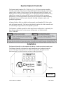
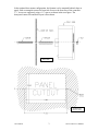
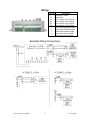
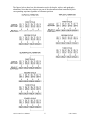
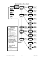
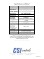
Spartan
By CSI Controls
CSLC-1900
4-20mA Setpoint Controller
User’s Manual
Spartan Setpoint Controller
The Spartan (model number CSLC-1900) is a CULUS 508 Listed setpoint controller,
featuring a powered 4-20 mA input with scalable digital readout, four dry contact relay
outputs, and a scalable 4-20 mA output. The four-character digital LED display will
display process values of 0.00 through 99.99, or 0 through 9999. Each of the four relay
outputs has a unique ON setting and OFF setting, allowing flexibility in setpoint
differential, even allowing normally-closed-type relay operation. For added flexibility,
the Spartan features a built-in output alternator, allowing for duplex, triplex, and
quadraplex applications.
A Battery Back-up Pack is available (sold separately, model number PP-1) that works
with the Spartan controller. This battery plugs directly into the side of the controller and
is automatically charged whenever the Spartan is powered.
The Spartan is available standard in a back-panel mount configuration, or optionally in a
door mount configuration. For door mount configuration, use model number:
CSLC-1900-DM.
Installation
The Spartan Controller is to be mounted only indoors or inside an enclosed control panel.
The Spartan Controller is designed for simple installation on a backpanel using two
screws. The image below shows screw hole size and location. The panel cut-out
dimensions and screw hole locations are shown in the figure below.
All dimensions
shown in inches
CSLC-1900 User’s Manual
2
CSI Controls
In the optional door-mount configuration, the Spartan is to be mounted behind a door or
panel, with a rectangular cutout for front-side access to the front face of the controller.
15/8” screws are suggested, using a 1¼” spacer as shown in the next figure. The
door/panel cutout size and hole layout is also shown.
SIDE VIEW
All dimensions
shown in inches
CSI Controls
3
CSLC-1900 User’s Manual
Wiring
Terminal
L
N
R1
R2
R3
R4
1
2
3
4
5
Description
Power Input, 120Vac
Neutral Input
Relay 1 Output - Dry Contacts
Relay 2 Output - Dry Contacts
Relay 3 Output - Dry Contacts
Relay 4 Output - Dry Contacts
4-20mA Output Negative Signal
4-20mA Output Positive Signal
4-20mA Output Power Supply
4-20mA Input Return Signal
4-20mA Input Power Supply
Example Wiring Connections
CSLC-1900 User’s Manual
4
CSI Controls
Controller Operation
4-Digit Digital
LED Display
Output 1
Relay Status
Menu
Navigation
Buttons
Output 2
Relay Status
Output 3
Relay Status
Output 4
Relay Status
Output Relay Status Indication Lights
Relay status indication lights show the status of the controller’s four output relays. If a
relay is closed, then the corresponding LED will be lit. If a relay is open, then the
corresponding LED will be off.
Alternation Operation
The Spartan Setpoint Controller is equipped with a programmable duplex, triplex, and
quadraplex alternator. By factory default, the alternation is turned off. See the description
of the “ALt” setting in the Setpoint Options Menu for instructions on how to turn on the
alternation feature.
An alternator cycles the same “run” command to a different output on successive run
cycles. In the Spartan, the alternator function works by rotating the relay that each
setpoint controls. At controller power-up, all relays start out in the “off” position.
Whenever one or more of the alternating relay outputs (1 and 2 for duplex; 1, 2, and 3 for
triplex; 1, 2, 3, and 4 for quadraplex) turns on because its setpoint has been reached, the
alternator is “armed”. Once armed, the alternator waits for all alternating relays to turn
off. When this happens, the alternator is triggered to switch, and the control of all
alternating relay outputs rotates to the next setpoint.
(Alternator Operation continued on next page)
CSI Controls
5
CSLC-1900 User’s Manual
The figures below show how this alternation works for duplex, triplex, and quadraplex
alternation. Note that relays that are not part of the alternation remain controlled by their
corresponding setpoints regardless of alternator position.
CSLC-1900 User’s Manual
6
CSI Controls
Tips for Using Alternation
The alternator switches as soon as all alternating relays become in the “off” state. It
does not necessarily designate any of the relays as a “lead” relay or a “lag” relay.
However, to make the Spartan’s alternation work like a standard discrete Duplexer,
Triplexer, or Quadraplexer, the following conventions are suggested when using the
alternator:
• Always make the On 1/OFF1 settings your “Lead” (or, first to turn on) output
settings.
• Always make the On 2/OFF2 settings your “Lag” or “Lag1” (second to turn on)
output settings.
• For triplex and quadraplex alternation, always make the On@3/OFF3 settings your
“Lag2” (third to turn on) output settings.
• For quadraplex alternation, always make the On 4/OFF4 settings your “Lag3” (last to
turn on) output settings.
Note: Be sure that all alternating outputs will all be off at the same time at the end of each
cycle. If the output setpoints are programmed in a way that does not allow all alternating
outputs to be off at the same time, that alternator will never switch. For this reason, it is
suggested not to mix “standard” and “inverted” (On # is lower than OFF#) settings within the
alternating outputs.
CSI Controls
7
CSLC-1900 User’s Manual
Spartan Menu Flow Chart
1nPt
Press & Hold
Menu/Enter
Button
OvtS
SET
CHANGE
On #
SET
CHANGE
To Change Field
MENU
MENU
MENU
ENTER
ENTER
ENTER
1n C
OFF#
MENU
MENU
ENTER
ENTER
SET
CHANGE
To Change Field
SET
OvtC
1nSc
MENU
MENU
MENU
ENTER
ENTER
ENTER
CHANGE
dPon
SET
CHANGE
To Change Field
4 1n
SET
CHANGE
To Change Field
MENU
ENTER
201n
SET
CHANGE
To Change Field
MENU
ENTER
Display Key
1nPt – Scaled Input Value
1n C – Input Current
OvtC – Output Current
OvtS – Output relay setpoints
menu
1nSc – Input scaling menu
SPOP – Setpoint options menu
OPSc – Output scaling menu
btOP – Battery backup operation
settings menu
On # - Relay turn on setpoint, # is
output relay number
OFF# - Relay turn off setpoint, # is
output relay number
dPon – Decimal point setting
4 1n – 4mA input scale setting
201n – 20mA input scale setting
ALt – Alternator setting
4 SP – 4mA output setpoint
20SP – 20mA output setpoint
PFr# - Relay on/off during power
fail, # is output relay
number
PFOc – 4-20mA output current loop
on/off during power fail
PFAr – Power failure alarm relay
selection
CSLC-1900 User’s Manual
SPOP
SET
CHANGE
ALt
SET
CHANGE
To Change Field
MENU
MENU
ENTER
ENTER
OPSc
SET
CHANGE
4 SP
MENU
MENU
ENTER
ENTER
20SP
SET
CHANGE
To Change Field
SET
CHANGE
To Change Field
MENU
ENTER
btOP
SET
CHANGE
PFr#
SET
CHANGE
To Change Field
MENU
MENU
ENTER
ENTER
PFOc
SET
CHANGE
To Change Field
MENU
ENTER
PFAr
SET
CHANGE
To Change Field
MENU
ENTER
8
CSI Controls
Menus
Menu Navigation
To advance to the next menu item, press the “Menu/Enter” button. When in the
display menu, to go to the main menu, push and hold “Menu/Enter” until you see
the “OvtS” appear on the LED screen (about 3 seconds). When in the Main Menu,
to select a submenu, press the “Set/Change” button.
Editing Fields
To edit the setting currently being displayed on the screen, press the “Set/Change”
button. The value that is now being edited will begin to flash. To change this
value, press the “Set/Change” button. To move to the next digit to edit, or to
finish editing the setting, press the “Menu/Enter” button.
Display Menu
Press Menu/Enter Button to change between menu fields
InPt – (Input Level):
Display will alternate showing “InPt” and the current value.
Reads out the scaled input value represented by the 4-20mA input signal.
In C - (Input Current):
Display will alternate showing “In C” and the current value.
Reads out the number of mA currently flowing through the 4-20mA input.
(Possible Values: 0.00 to 20.00)
OVtC - (Output Current):
Display will alternate showing “OvtC” and the current value.
Reads out the number of mA currently flowing through the 4-20mA
output. (Possible Values: 0.00 to 20.00)
User Settings Main Menu
Press and hold Menu/Enter Button for 3 seconds while in the Display Menu
to enter into this menu. Press the Menu/Enter Button to change between
menu fields.
OVtS - (Output relay Setpoints menu):
Press Set/Change button to enter into this sub-menu.
InSc - (Input Scaling settings menu):
Press Set/Change button to enter into this sub-menu.
SPOP - (Setpoint Options menu):
Press Set/Change button to enter into this sub-menu.
CSI Controls
9
CSLC-1900 User’s Manual
OPSc – (Output Scaling settings menu):
Press Set/Change button to enter into this sub-menu.
btOP – (Battery backup Operation settings menu):
Press Set/Change button to enter into this sub-menu.
OutS Output Relay Setpoints Menu
On # - (Relay turn-on setpoint, # is output relay number):
Display will alternate showing “On #” and the current value.
When the scaled input value is equal to the value entered in this field the
corresponding relay will turn on.
Press Set/Change button to change this field.
OFF# - (Relay turn-off setpoint, # is output relay number):
Display will alternate showing “OFF#” and the current value.
When the scaled input value is equal to the value entered in this field the
corresponding relay will turn off.
Press Set/Change button to change this field.
Note: If the ON # setpoint is higher than the OFF# setpoint, then the relay will turn on
when the scaled input value gets up to or above the ON # setting, and turns back off when
the scaled input value gets back down to or below the OFF# setting. If the ON # setpoint is
lower than the OFF# setpoint, then the relay will turn on when the scaled input value gets
down to or below the ON # setpoint, and will turn back off when the scaled input value
gets back up to the OFF# setpoint. The ON # and OFF# setpoints must be at least 2 digit
values apart (Ex: OFF2 = 0058, ON 2 = 0060 or OFF4 = 02.25, ON 4 = 02.27). If they are
not, the program will automatically adjust them so they are.
InSc Input Scaling Settings Menu
dPon - (Decimal Point On):
Display will alternate showing “dPon” and the current value.
Controls whether a decimal point is displayed on scaled input values.
Press Set/Change button to change this field.
Possible Settings:
0 = (Default Setting) The decimal point will not be displayed on scaled
input values. This allows for possible input value scaling of 0
through 9999.
1 = The decimal point will be displayed on scaled input values. This
allows for possible input value scaling of 0.00 through 99.99.
CSLC-1900 User’s Manual
10
CSI Controls
4 In - (4mA Input scale value):
Display will alternate showing “4 In” and the current value.
When the input current is 4mA, the scaled input value will be equal to this
value.
(Possible Values: 0000-9999 or 00.00 through 99.99)
Press Set/Change button to change this field.
20In - (20mA Input scale value)
Display will alternate showing “20In” and the current value.
When the input current is 20mA, the scaled input value will be equal to
this value.
(Possible Values: 0000-9999 or 00.00 through 99.99)
Press Set/Change button to change this field.
Note: The 4mA input scale value and the 20mA input scale value can be any value in the
given range. It is possible to set the 20mA input scale value lower than the 4mA input
scale value. If this is done, the scaled input value will decrease as the 4-20mA input
current increases.
SPOP Setpoint Options Menu
ALt - (Alternator setting):
Display will alternate showing “ALt” and the current value.
Controls whether the relay outputs alternate. See Alternation Operation
section for more details.
Press Set/Change button to change this field.
Possible Settings:
0 = (Default Setting) No alternation. Each relay output turns on and off
according to its corresponding ON and OFF setpoints.
1 = Duplex Alternation. Relay outputs 1 and 2 alternate. Relay outputs 3
and 4 turn on and off according to their corresponding ON and
OFF setpoints.
2 = Triplex Alternation. Relay outputs 1, 2, and 3 alternate. Relay output 4
turns on and off according to its corresponding ON and OFF
setpoints.
3 = Quadraplex Alternation. Relay outputs 1, 2, 3, and 4 alternate.
CSI Controls
11
CSLC-1900 User’s Manual
OutS Output Scaling Settings Menu
4 SP - (4mA output Setpoint):
Display will alternate showing “4 SP” and the current value.
When the scaled input value is equal to this value, the mA output will be
equal to 4mA.
(Possible Values: 0000-9999 or 00.00 through 99.99)
Press Set/Change button to change this field.
20SP - (20mA output Setpoint):
Display will alternate showing “20SP” and the current value.
When the scaled input value is equal to this value, the mA output will be
equal to 20mA.
(Possible Values: 0000-9999 or 00.00 through 99.99)
Press Set/Change button to change this field.
Note: The 4mA output setpoint and the 20mA output setpoint can be any value in the
given range. It is possible to set the 20mA output setpoint lower than the 4mA output
setpoint. If this is done, the 4-20mA output current will decrease as the scaled input value
increases. Also, the user should be aware that the 4mA and 20mA output setpoints can be
set outside the Input Scaling range that is set in the Input Scaling Settings Menu. For
example, if the 4mA Input scale is set to 0000 and the 20mA Input scale is set to 1000,
the 20mA output setpoint can still be set to 1275, even though the system won’t be able
to register any scaled input value above 1000. The 4-20mA output current, in this case,
would never be able to reach the 20mA value.
btOP Battery Backup Operation Settings Menu
PFr# - (Relay On/Off during power fail, # is output relay number):
Display will alternate showing “PFr#” and the current value.
Press Set/Change button to change this field.
Possible Settings:
1 = (Default Setting) The relay will continue normal operation during
power failure (if battery backup pack is plugged into it).
0 = To conserve battery power the relay will turn off during a power
failure.
CSLC-1900 User’s Manual
12
CSI Controls
PFOc - (4-20mA output current loop On/Off during power fail):
Display will alternate showing “PFOc” and the current value.
Press Set/Change button to change this field.
Possible Settings:
1 = (Default Setting) The 4-20mA current loop will continue normal
operation during a power failure (if a battery backup pack is
plugged into it).
0 = To conserve battery power the 4-20mA current loop will turn off
during a power failure.
PFAr - (Power Failure Alarm Relay selection)
Display will alternate showing “PFAr” and the current value.
Press Set/Change button to change this field.
Possible Settings:
0 = (Default Setting) No relays will indicate the power failure condition.
1-4 = Selects which output relay will close to indicate a power failure
condition.
Note: Battery backup pack must be used for this feature to work.
CSI Controls
13
CSLC-1900 User’s Manual
Specifications and Ratings*
Dimensions
Mounting
Weight
3.00"h X 5.25"w X 1.45"d
Backpanel Mount (standard), Door Mount (optional)
0.6 pounds
120VAC only
Power Supply Input
(fuse using 0.5 amp fast blow fuse)
Dry Contact; 3 amp 240VAC (resistive)
R1, R2, R3, R4 Outputs
or 2.88 amp pilot duty
4-20mA Input Power
16Vdc – 24Vdc, 40 mA max.***
Supply (terminal 5)
4-20mA Output Power
10Vdc – 15Vdc, 40 mA max.***
Supply (terminal 3)
Max. Allowed External
Loop Resistance
350 Ohms max.
For Self-Powered
(650 Ohms max. if powered from terminal 5)
4-20mA Output
Internal 4-20mA Output
150 Ohms
Loop Impedance
External 4-20mA Output
9Vdc – 30Vdc
Power Supply Voltage
UL Listed Class 2
Relay Status Indicators
Red LEDs
Fresh Battery Life on a
Power Fail with 1
Relay On, Output
Approx. 9 Hours
Current turned off, and
12 mA input current**
4.5 in-lbs Terminal Torque
Terminal Ratings
Use 12-28AWG copper wire only
Controller Temp Range
-40°F (-40°C) to +185°F (85°C)
Humidity
95% non-condensing
UL Listed (US & Canada)
File #E225901
*Equipment was evaluated at an ambient air temperature of 25°C.
**Battery life will vary greatly depending on the field conditions when the battery
power is being used. The optional battery pack (part number: PP1) automatically
recharges when normal power is restored.
***45mA maximum for terminals 3 and 5 combined.
CSI Controls, 220 Ohio Street, Ashland, Ohio 44805 · Phone 419-281-5767 · FAX 419-289-2535
©2010 CSI
www.CSIcontrols.com
[email protected]
1030833 Jan11