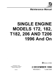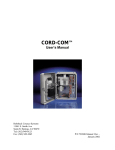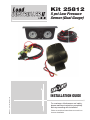
1
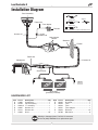
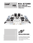
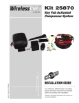
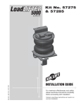
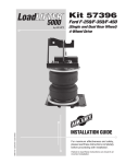
MN-337 • (111107) • ECR 7119
™
Kit 25812
5 psi Low Pressure
Sensor (Dual Gauge)
INSTALLATION GUIDE
For maximum effectiveness and safety,
please read these instructions completely
before proceeding with installation.
Failure to read these instructions can result in an
incorrect installation.
TABLE OF CONTENTS
Introduction . . . . . . . . . . . . . . . . . . . . . . . . . . . . . . . . . . . . . . . 2
Important Safety Notice . . . . . . . . . . . . . . . . . . . . . . . . . . . . . . . . . . . . . . . . . . . . . 2
Notation Explanation . . . . . . . . . . . . . . . . . . . . . . . . . . . . . . . . . . . . . . . . . . . . . . . . 2
Installation Diagram . . . . . . . . . . . . . . . . . . . . . . . . . . . . . . . . 3
Hardware List . . . . . . . . . . . . . . . . . . . . . . . . . . . . . . . . . . . . . . . . . . . . . . . . . . . . . 3
Installing the Load Controller II System . . . . . . . . . . . . . . . . 4
Getting Started . . . . . . . . . . . . . . . . . . . . . . . . . . . . . . . . . . . . . . . . . . . . . . . . . . . . 4
Recommended Compressor Locations . . . . . . . . . . . . . . . . . . . . . . . . . . . . . . . . . . 4
Step by Step Installation . . . . . . . . . . . . . . . . . . . . . . . . . . . . . . . . . . . . . . . . . . . . . 5
Warranty and Returns Policy . . . . . . . . . . . . . . . . . . . . . . . . . 8
Replacement Information . . . . . . . . . . . . . . . . . . . . . . . . . . . . 9
Contact Information . . . . . . . . . . . . . . . . . . . . . . . . . . . . . . . . 9
1
Load Controller II
Introduction
The purpose of this publication is to assist with the installation of the Load Controller II
compressor system.
It is important to read and understand the entire installation guide before beginning installation
or performing any maintenance, service or repair. The information here includes a hardware
list and step-by-step installation information.
Air Lift Company reserves the right to make changes and improvements to its products and
publications at any time. Contact Air Lift Company at (800) 248-0892 or visiti us online at
www.airliftcompany.com for the latest version of this manual.
IMPORTANT SAFETY NOTICE
The installation of this kit does not alter the Gross Vehicle Weight Rating (GVWR) or payload
of the vehicle. Check your vehicle’s owner’s manual and do not exceed the maximum load
listed for your vehicle.
Gross Vehicle Weight Rating: The maximum allowable weight of the fully loaded vehicle
(including passengers and cargo). This number — along with other weight limits, as well
as tire, rim size and inflation pressure data — is shown on the vehicle’s Safety Compliance
Certification Label.
Payload: The combined, maximum allowable weight of cargo and passengers that the truck
is designed to carry. Payload is GVWR minus the Base Curb Weight.
NOTATION EXPLANATION
Hazard notations appear in various locations in this publication. Information which is
highlighted by one of these notations must be observed to help minimize risk of personal injury
or possible improper installation which may render the vehicle unsafe. Notes are used to help
emphasize areas of procedural importance and provide helpful suggestions. The following
definitions explain the use of these notations as they appear throughout this guide.
DANGER
INDICATES IMMEDIATE HAZARDS WHICH WILL RESULT IN SEVERE PERSONAL
INJURY OR DEATH.
WARNING
INDICATES HAZARDS OR UNSAFE PRACTICES WHICH COULD RESULT IN SEVERE
PERSONAL INJURY OR DEATH.
CAUTION
INDICATES HAZARDS OR UNSAFE PRACTICES WHICH COULD RESULT IN DAMAGE
TO THE MACHINE OR MINOR PERSONAL INJURY.
NOTE
2
Indicates a procedure, practice or hint which is important to highlight.
MN-337
Load Controller II
Installation Diagram
Panel Assembly
Adapter #1
Adapter
Adapter #2
Power wire
Fuse
Fuse adapter
Adapter #3 *
Fuse box
In line
15 AMP fuse
Harness #1
* Uses 3/16 (smaller) Female Push On Connector
Low pressure
sensors
Grommet
Firewall
Power wire
Compressor
Harness #2
Check valves
Ground
fig. 1
Air springs
(previously installed)
HARDWARE LIST
Item
A
B
C
D
E
F
Part #
16060
26159
26061A
26087
26110
20225
Description................................Qty
Compressor.................................. 1
Panel assembly ............................ 1
“Y” assembly ................................ 1
Harness #1 ................................... 1
Harness #2 ................................... 1
Hose............................................25’
Item
G
H
I
J
K
L
Part #
20035
24542
24543
24561
24643
20788
Description...............................Qty
Grommet ...................................... 1
Fuse ............................................. 1
Fuse ............................................. 1
Fuse adapter ................................ 1
Red wire......................................16’
Black wire ..................................... 8’
Missing or damaged parts? Call Air Lift customer
service at (800) 248-0892 for a replacement part.
MN-337
3
Load Controller II
Installing the Load Controller II System
GETTING STARTED
This part of the installation should be done after the air spring kit is installed. If you
have any questions, please call Air Lift customer service at (800) 248-0892.
If you are adding this control system to an Air Lift SuperDuty application, then no modifications
to the low pressure sensor are necessary. If you are adding this control system to an Air
Lift 1000 or RideControl application, and if your specific application requires a minimum of
10 p.s.i., then it will be necessary to adjust the low pressure sensor to 10 p.s.i. To increase
the pressure in the low pressure sensor, remove the rubber plug with pliers (fig. 2). Using
an allen wrench, turn the screw clockwise 4 1/4 turns (fig. 3). Push the rubber plug back into
the top of the low pressure sensor. Proceed with the step by step installation instructions.
Do not cut, trim, modify, or disassemble the harness. If you have excess length, simply coil
it up and secure out of the way with the provided tie straps. All preassembled gauge panels
have been 100% leak & function tested. DO NOT attempt to tighten, loosen, or adjust any
fittings or connections. This will likely cause a leak or malfunction and void the warranty.
Remove
rubber cap
Turn allen screw 4 ¼
turns clockwise
fig. 2
fig. 3
RECOMMENDED COMPRESSOR LOCATIONS
Important
LOCATE COMPRESSOR IN DRY, PROTECTED AREA ON VEHICLE.
DIRECT SPLASH OR ExCESSIVE MOISTURE CAN DAMAGE
THE COMPRESSOR AND CAUSE SYSTEM FAILURE.
Disclaimer: If you choose to mount the compressor outside the vehicle please keep in
mind the compressor body must be shielded from direct splash and the intake should be
snorkeled inside the vehicle. If the compressor does not include a remote mount air filter or
if mounting the compressor outside the vehicle, make sure to orient the compressor intake
filter so that all moisture can easily drain.
Please also remember...
• To avoid high heat environments
• To avoid mounting the compressor under the hood.
• To check to be sure the compressor harness #2 will reach the compressor and connect
to harness #1.
• The compressor can be mounted in any position — vertical, upside down, sideways,
etc. (please refer to the instruction manual).
4
MN-337
Load Controller II
STEP BY STEP INSTALLATION
All of the electrical connections are matched by male-to-female push-in terminals. All of the
air line connections will be white- to-white, no tape-to-no tape, indicated by the color band.
The color band also serves as a reference point for installing the air line into the fitting.
Properly installed, the front edge of the color band should be against the collar of the fitting
(fig. 4 and 5).
No tape tee
No tape
air line
Harness #1
White
banded tee
White banded
air line
fig. 4
No tape air line
to no tape tee
Harness #2
Harness #1
Gauge side
White
banded air
line to white
banded tee
fig. 5
Compressor side
Power (red) wires
1. Install the gauge panel. Select a convenient mounting location that has a sturdy rigid
surface. The bottom edge of the dash on either side of the steering wheel is a good
location. Attach the panel to the selected location with the black self-tapping screws.
2. Install the compressor unit.
a. Hold the compressor in the recommended location (fig. 6) and use the provided silver
self tapping screws to attach the mounting brackets to the vehicle.
b. In some cases the mounting area does not provide enough room to use a drill to
drive the screws in. It may be necessary to use the mounting brackets as a template
to drill 13/64” holes through the frame first and then use a 7/16” nut driver to install
the self tapping screws.
NOTE
Attach the ground wire to one of the screws (fig. 1).
c. For box frames: In some cases the frame section will not be wide enough to mount
the compressor legs flat to the rail. Refer to fig. 6 in this situation.
CAUTION
MN-337
DO NOT DRILL ANY HOLES INTO THE FRAME OR THE FLOOR BOARD BEFORE
CHECKING FOR HYDRAULIC LINES, GAS LINES, AND/OR ELECTRICAL WIRES
THAT MAY NEED TO BE MOVED ASIDE. ALSO, WHEN ATTACHING TO THE FLOOR
BOARD, IT IS IMPORTANT TO CHECK WHERE THE SCREWS PROTRUDE THROUGH
THE FLOOR BOARD. IT MAY BE NECESSARY TO TRIM OR COVER THE TOP OF THE
SCREWS INSIDE THE VEHICLE. A SEALER SHOULD BE USED AROUND THE SCREW
5
Load Controller II
TO PREVENT THE ELEMENTS FROM ENTERING THE CAB AREA.
Frame
Floor plan
Compressor
Compressor
L-bracket
fig. 6
Supplied self
tapping screw
¼” Bolt and nut will need to
be provided if the L-bracket
is fabricated.
3. Connect wiring harness #1 to the back of the gauge panel.
a. With your thumb against the front side of the switch, connect the wire by pushing
the female connectors onto the blade connectors on the switch.
b. Match the air line by the color band on the air line to the color band on the tees.
c. Push the air lines onto the “T” fittings until the air line completely covers the barb
(fig. 4). Lubricating the air line will ease pushing the air line over the barb.
d. Do not connect the power wire at this time.
e. Wiring harness #1 also connects the gauge panel to the low pressure sensor
assemblies. The low pressure sensors protect the air springs from failure resulting
from low pressure in the unloaded condition. These sensors are preset to maintain
a MINIMUM pressure of 5 psi in the air springs. The sensors measure the pressure
in each spring and turn on the compressor if the pressure falls below 5 psi.
NOTE
The low pressure sensors are preassembled onto wiring harness #1. The sensors should
be located under the dash inside the vehicle and secured with the provided tie straps.
4. Push the air line coming from the “Y” assembly onto the barb fitting on the compressor.
Make sure the air line covers all barbs. A small amount of water or lubricant and pushing
with a slight circular motion will ease installation (fig. 7).
5. Connect the check valves and power wire on harness #2 to the “Y” assembly as shown
in fig. 1. Do not overtighten the check valve connector. Hand tight is sufficient.
Air line
Harness #2
fig. 7
Barbed fitting/
check valve
Ground
Power (red) wires
6. Route wiring harness #2 from the compressor.
a. Use existing grommets in the floorboard or firewall to route the harness from the
compressor to the low pressure sensors on harness #1.
6
MN-337
Load Controller II
b. In some cases, a hole may have to be drilled to allow access for the harness. Drill
a 1” diameter hole and install the provided grommet (fig. 8). It will be necessary to
seal any grommets or holes that have been cut, drilled or removed so as not to allow
elements to enter the cab area of the vehicle.
c. When routing wiring harness #2 from the compressor, it should not be routed so as
to lay on, or near, the exhaust pipe/muffler/catalytic convertor of the vehicle. Routing
along the top of a crossmember or over a heat shield is recommended.
After the hole is drilled and before
you route the harness to through the
firewall, insert the grommet and “walk”
the material around the inside edge of
the dilled hole. You may have to trim
the grommet to get an exact fit.
(The flexible grommet is in the sealed
parts package.)
fig. 8
7. Connect wiring harness #2 to wiring harness #1 inside the vehicle by connecting the red
wire from harness #2 and the banded and no tape air lines to the low pressure sensors.
See fig. 5 for air line and electrical connection.
8. The next connection is between each air spring and the air line “T” fitting located just
ahead of the check valves in harness #2 (fig. 1 and 7).
a. With the air springs deflated, use a hose cutter or razor blade to cut the air line
already installed between the air springs and the inflation valves.
b. Install the provided “T” fittings (fig. 1) by pushing the air line into each leg of the “T”
until you feel a definite “click”. Each line should go in 9/16”.
c. Connect a single length of air line to the open leg of each “T”. Bring each of the lines
to the “T” fittings in harness #2 just in front of the check valves and connect as shown
in fig. 7.
d. Route the air line across the chassis from the far side over the exhaust system heat
shields and along the frame up to the compressor. Avoid heat sources, sharp edges,
and tight bends.
9. Connect the power wire from harness #1.
a. Route it to the vehicle fuse box.
b. Use a test light to determine which open terminal (accessory, etc.) works only when
the key is in the “on” or accessory position (or refer to the owners manual for an
available accessory fuse). The terminal should have an amperage rating equal to
or higher than the 15 amp in-line fuse.
c. Connection to the fuse terminal will depend on what type of fuse your vehicle uses.
If your vehicle uses the barrel type fuse, use adapter #1. If you have the standard
spade type fuses, use adapter #2. Many late model vehicles use a smaller spade
type fuse which requires adapter #3 (see inset with fig. 1). If adapter #1 or #2 are
used, it will be necessary to cut off the ¼” female connector attached to the power
wire and crimp the smaller 3/16” female connector supplied with this kit.
NOTE
Connect adapter to “HOT” side of the fuse (use a test light to determine). With the ignition
on, the compressor will turn on and fill the system to 10 p.s.i. before shutting off.
10. Connect the gauge light.
a. Attach a ¼” female connector to both the red and black wires.
MN-337
7
Load Controller II
b. Plug the wires into the ¼” male terminals on the back of the gauge light.
c. Route the red wire for the illuminated gauge to harness number one’s fused wire or
to a dash light wire circuit and attach with the quick splice provided.
d. Ground the black wire to an adequate ground. Use the additional wire and connectors
supplied if longer leads are needed (fig. 1).
11. Press the off/on button to inflate both air springs and use the small deflate button to
adjust the pressure. Inflate to 30 p.s.i. (20 p.s.i. for Air Lift 1000 kits). Check all fittings
and inflation valve cores with a solution of 1/5 dish soap to 4/5 water in a spray bottle
for leaks.
12. Recheck air pressure after 24 hours. A 2–4 p.s.i. loss after initial installation is normal.
If pressure has dropped more than 5 p.s.i., re-test for leaks with soapy water solution.
Please read and follow the maintenance and operating tips in the installation manual
that came with your air spring kit.
IMPORTANT: If the compressor runs continually or often, then there is a leak. Disconnect
the compressor at the fuse box and test for leaks with a soapy water solution.
CAUTION
NEVER RUN THE COMPRESSOR LONGER THAN FOUR MINUTES CONTINUOUSLY.
ALLOW AT LEAST FIVE MINUTES FOR COOL DOWN BEFORE STARTING THE
COMPRESSOR AGAIN.
Warranty and Returns Policy
Air Lift Company warrants its products, for the time periods listed below, to the original
retail purchaser against manufacturing defects when used on catalog-listed applications on
cars, vans, light trucks and motorhomes under normal operating conditions for as long as
Air Lift manufactures the product. The warranty does not apply to products that have been
improperly applied, improperly installed, used in racing or off-road applications, used for
commercial purposes, or which have not been maintained in accordance with installation
instructions furnished with all products. The consumer will be responsible for removing
(labor charges) the defective product from the vehicle and returning it, transportation costs
prepaid, to the dealer from which it was purchased or to Air Lift Company for verification.
Air Lift will repair or replace, at its option, defective products or components. A minimum
$10.00 shipping and handling charge will apply to all warranty claims. Before returning
any defective product, you must call Air Lift at (800) 248-0892 in the U.S. and Canada
(elsewhere, (517) 322-2144) for a Returned Materials Authorization (RMA) number.
Returns to Air Lift can be sent to: Air Lift Company • 2727 Snow Road • Lansing, MI •
48917.
Product failures resulting from abnormal use or misuse are excluded from this warranty. The
loss of use of the product, loss of time, inconvenience, commercial loss or consequential
damages is not covered. The consumer is responsible for installation/reinstallation (labor
charges) of the product. Air Lift Company reserves the right to change the design of any
product without assuming any obligation to modify any product previously manufactured.
This warranty gives you specific legal rights and you may also have other rights that vary
from state-to-state. Some states do not allow limitations on how long an implied warranty
lasts or allow the exclusion or limitation of incidental or consequential damages. The above
limitation or exclusion may not apply to you. There are no warranties, expressed or implied
including any implied warranties of merchantability and fitness, which extend beyond this
warranty period. There are no warranties that extend beyond the description on the face
hereof. Seller disclaims the implied warranty of merchantability. (Dated proof of purchase
required.)
8
MN-337
Load Controller II
(Warranty and Returns Policy continued)
Air Lift 1000 .................... Lifetime Limited
RideControl .................... Lifetime Limited
LoadLifter 5000*............. Lifetime Limited
SlamAir ........................... Lifetime Limited
AirCell ............................. Lifetime Limited
Lifestyle & Performance** .... 1 Year Limited
LoadController/Single ...... 2 Year Limited
LoadController/Dual ......... 2 Year Limited
Load Controller (I) ............ 2 Year Limited
Load Controller (II) ........... 2 Year Limited
SmartAir ............................ 2 Year Limited
Wireless AIR...................... 2 Year Limited
WirelessONE ..................... 2 Year Limited
Other Accessories ............ 2 Year Limited
*formerly SuperDuty
**formerly EasyStreet
Replacement Information
If you need replacement parts, contact the local dealer or call Air Lift customer service at
(800) 248-0892. Most parts are immediately available and can be shipped the same day.
Contact Air Lift Company customer service at (800) 248-0892, first if:
• Parts are missing from the kit.
• Need technical assistance on installation or operation.
• Broken or defective parts in the kit.
• Wrong parts in the kit.
• Have a warranty claim or question.
Contact the retailer where the kit was purchased:
• If it is necessary to return or exchange the kit for any reason.
• If there is a problem with shipping if shipped from the retailer.
• If there is a problem with the price.
Contact Information
If you have any questions, comments or need technical assistance contact our customer service
department by calling (800) 248-0892, Monday through Friday, 8 a.m. to 7 p.m. Eastern Time.
For calls from outside the USA or Canada, our local number is (517) 322-2144.
For inquiries by mail, our address is PO Box 80167, Lansing, MI 48908-0167. Our shipping
address for returns is 2727 Snow Road, Lansing, MI 48917.
You may also contact us anytime by e-mail at [email protected] or on the web at
www.airliftcompany.com.
MN-337
9
Need Help?
Contact our customer service department by calling
(800) 248-0892, Monday through Friday, 8 a.m. to
7 p.m. Eastern Time. For calls from outside the USA
or Canada, our local number is (517) 322-2144.
Register your warranty online at
www.airliftcompany.com/warranty
Thank you for purchasing Air Lift products — the professional installer’s choice!
Air Lift Company • 2727 Snow Road • Lansing, MI 48917 or PO Box 80167 • Lansing, MI 48908-0167
Toll Free (800) 248-0892 • Local (517) 322-2144 • Fax (517) 322-0240 • www.airliftcompany.com
Printed in
the USA