1
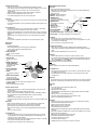
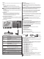
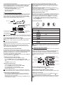
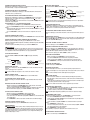
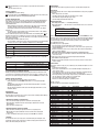
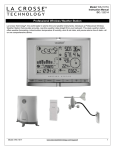
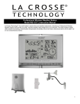
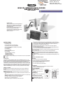
99 Washington Street
Melrose, MA 02176
Phone 781-665-1400
Toll Free 1-800-517-8431
WS831DL WIRELESS DATA LOGGING
WEATHER STATION
USER’S MANUAL
Visit us at www.TestEquipmentDepot.com
INTRODUCTION
Thank you for purchasing General’s Data Logging Wireless
Weather Station. This compact and easy-to-use product
uniquely measures and monitors weather data right at
your immediate location.
It includes a wide range of weather features plus precise
atomic time and perpetual calendar. Weather
measurements include: air temperature, relative humidity,
barometric pressure, wind speed and direction,
rainfall levels and more.
PACKAGE CONTENTS
In this package you will find:
• One Main Unit (receiver)
• One Rain Gauge (remote rain sensor/transmitter)
• One Anemometer (remote wind sensor/transmitter)
• Two Three-Channel Temperature & Humidity Sensor (transmitter)
• One 7.5V AC/DC Adapter
• One CD-ROM disk
• One 6 ft (2m) USB cable
• Mounting Hardware with wrench tool
• One User’s Manual
Required for installation (not included)
- Small Phillips screwdriver
- Anemometer mounting pole
- Small paper clip to reset sensors
NOTE: If any items are missing or damaged, please contact Customer Service before proceeding with
installation.
INSTALLATION
General’s Wireless Data Logging Weather Station operates at 433MHz radio frequency, so no wire
installation is required between the main unit (receiver) and the remote weather sensors (transmitters).
The remote weather sensors include (2) thermo-hygrometer (temperature and humidity) sensors,
anemometer (wind sensor) and a rain gauge (rain sensor). All data measured by these remote sensors
is transmitted to the main unit wirelessly, with the operating range up to 328 feet (100 meters) in the
open area. The Anemometer and a rain gauge must be placed outdoors to measure weather elements.
Remote thermo-hygrometers can be placed indoors or outdoors. If you intend measuring outdoor
temperature and humidity, place the remote sensor outdoors, preferably not in the direct sunlight.
BEFORE YOU BEGIN
The components of this complete Wireless Weather Station operate wirelessly at 433MHz radio
frequency.
No interconnecting wires are required between the main unit (receiver) and the remote sensors
(transmitters). Power up and test communications between all of the sensors and the main unit
BEFORE mounting them outside.
• For most applications alkaline batteries are acceptable where temperatures remain above 32°F
(0°C).
• Avoid using rechargeable batteries. (Rechargeable batteries do not provide correct power levels).
• ALWAYS install batteries in the remote sensors before the main unit.
• Insert batteries matching the polarity in the battery compartment.
• Remove plastic sleeve from LCD display (if any).
• During an initial setup, place the main unit close to the remote sensors.
• After reception is established (all of the remote readings will appear on the main unit’s display),
position the remote sensors and the main unit within the effective transmission range of up to 328
feet (100 meters). Ideally they should be placed within the line of sight of the main unit. See
placement tips in the user manual for each remote sensor.
• Transmission range may be affected by trees, metal structures and electronic appliances.
• The main unit must be placed indoors.
• The effective operating range may be influenced by the surrounding building materials and how
the receiver (main unit) and transmitters (sensors) are positioned.
• Place the remote sensors so that they face the main unit (receiver), minimizing obstructions such as
doors, walls, and furniture.
• Make sure that the remote sensors are easily accessible for cleaning and maintenance.
NOTE: When the temperature falls below freezing, the outdoor sensor batteries may have reduced
voltage and a reduced effective range. We recommend using lithium batteries at temperatures
below 32°F (0°C).
IMPORTANT: We recommend cleaning the remote sensors periodically, as dirt and debris affects sensor
accuracy.
THERMO-HYGROMETER SENSOR
FEATURES
• LCD display of measured temperature and humidity.
• Remote data transmission to the main unit via 433 MHz signal.
• 328 feet (100 meters) transmission range without interference.
• Three (3) transmission channels selection.
• Case can be wall mounted using built-in hanger.
A. LED INDICATOR
• Flashes once when the remote sensor transmits a reading to the main unit.
• Flashes twice when battery power is low.
B. BATTERY COMPARTMENT
• Holds 2 “AA” batteries. (not included)
C. RESET
A
• Resets all readings (requires small
paper clip.)
C
D. CHANNEL SWITCH
• Selects the desired sensor channel from
1 to 3.
E. WALL-MOUNT RECESSED OPENING
• Keeps the remote sensor on the wall.
NOTE: Install the batteries and select the
channel before mounting the sensor.
E
F
D
B
BATTERY INSTALLATION
• Remove the screws from the battery compartment with a small Phillips screwdriver.
• Set the channel 1 through 3. The switch is located in the battery compartment. Set one sensor to
Channel 1 and the second sensor to Channel 2, etc. The sensors must operate on
separatechannels.
• Install 2 “AA” batteries matching the polarities shown in the battery compartment.
• Replace the battery compartment door and secure the screws.
• Secure the thermo-hygrometer remote sensor in the desired location.
MOUNTING
• The remote thermo-hygrometer sensor can be placed on the flat surface or mounted on the wall in
vertical position.
• Use the wall mount hardware and screws provided when mounting the thermo-hygrometer sensor
on the wall.
PLACEMENT TIPS:
• The remote thermo-hygrometer sensor should be placed in the area with a free air circulation
and sheltered from the direct sunlight and an extreme weather conditions.
• Ideally, place the thermo-hygrometer sensor above the natural surfaces (such as a grassy lawn).
• Avoid placing the thermo-hygrometer sensor near sources of heat such as chimneys and heating
elements.
• Avoid areas that collect or radiate heat from the sun, such as metal, brick/concrete structures,
paving,
or patio decks.
• The best location for temperature measurements is 4 feet (1.25meters) above the ground.
RAIN GAUGE
FEATURES
• Precipitation measurement.
• Remote rainfall data transmission to the main unit via 433 MHz signal.
• 100 feet (30 meters) transmission range without interference.
• Built-in installation level.
A. RAIN GAUGE BUCKET
Contains electronic components.
B. KNOB
Secures the top on the rain gauge bucket.
C. RAIN GAUGE FEET
Secures the rain gauge in
place.
D. FUNNEL-SHAPED TOP WITH
D
BATTERY COMPARTMENT
Contains battery compartment
and rainfall counting
electronics.
E
E. BATTERY COMPARTMENT
Holds two “AA” batteries.
F. SCREWS
Secures battery compartment
F
cover.
G. BUILT-IN LEVEL WITH BUBBLE
Ensures level rain gauge
mounting for proper operation.
H. BUCKET SEE-SAW MECHANISM
Collects the rainfall in one of its containers and self-empties once full.
I. PROTECTIVE SCREEN
Protects the rain gauge funnel from debris.
ANEMOMETER (WIND SENSOR)
FEATURES
• Wind speed and wind direction measurement.
• Remote wind speed and wind direction data transmission to the main unit via 433 MHz signal.
• Operating range 100 feet (30 meters).
• Wall or pole mount.
A. WIND VANE - Indicates wind direction.
B. WIND CUPS - Measures wind speed.
A
C. ANEMOMETER BASE
• Holds battery compartment.
• Allows mounting the anemometer vertically.
E
D. ANEMOMETER ARM
D
Connects battery to anemometer
B
head assembly.
E. WIND CUPS SHAFT
G
Holds wind cups on the a
nemometer arm.
F
H
F. BATTERY COMPARTMENT
C
Holds 2 “AA” batteries.
G. WALL MOUNT SCREW OPENINGS - Allows securing the anemometer in place.
H. BATTERY COVER - Secures battery compartment on the anemometer base.
ASSEMBLY
• Slide the wind cups on to the anemometer rotating shaft. Do not use force.
• Insert the Allen Wrench (provided) into the wind cup set screw opening. Tighten the set screw to
secure wind cups to the rotating shaft.
• Test to ensure cups are securely fastened to the shaft.
BATTERY INSTALLATION
• Remove four (4) screws from the battery compartment with a small Phillips screwdriver.
• Open the battery compartment and install 2 “AA” batteries (not included) matching the polarities
shown.
• Replace the battery compartment door and secure the screws.
ALIGNING
• Point the wind direction vane to the north (use a compass or map if necessary).
• Press the button inside the “SET” opening located inside battery compartment with a paper clip.
“SET” selects a new direction for NORTH and, when pressed repeatedly, alternates between the
factory default NORTH and user selected NORTH.
NOTE: Repeat this procedure after changing the batteries.
G
H
I
BATTERY INSTALLATION
• Unlock the funnel-shaped top on the rain gauge by turning both knobs on the sides in an anticlockwise direction.
• Remove the funnel-shaped top lifting it off the rain gauge bucket.
• Remove 7 small screws from the battery compartment cover using a small Phillips screwdriver.
• Insert 2 “AA” batteries (not included), matching the polarities as shown in the battery
compartment.
• Replace the battery compartment door and secure the screws.
• Insert the funnel-shaped top into the rain gauge bucket and secure it in place by turning the knobs
clockwise.
MOUNTING
• Make sure that the rain gauge bucket is level – check inside built-in level for bubble center.
• Place the protective screen over the top to protect the rain gauge from the debris.
• Where practical, mount the rain gauge in place with wood screws (not included).
• Make sure that the rain gauge is in open area where precipitation falls directly into the gauge’s
bucket,
ideally 2-3 feet above the ground.
PLACEMENT TIPS
• The rain gauge should be placed in an open area away from the walls, fences, trees and other
coverings which may reduce the amount of rain falling into the bucket. Additionally, trees and
rooftops may be sources of pollen and debris.
• To avoid the rain shadow effects, place the rain gauge horizontally, on the distance corresponding
to two to four times the height of any nearby obstruction.
• It is important to locate the unit where rain can flow away freely.
MOUNTING
Mount the anemometer onto a vertical surface, using the fittings provided.
PLACEMENT TIPS:
• The anemometer should be mounted in an open area with a free air flow; away from the nearby
trees, buildings or other structures.
• For optimal performance, mount the anemometer at 33 feet (10meters) above the ground in
unobstructed area.
MAIN UNIT
The main unit measures pressure, indoor temperature, humidity, and receives atomic time data from
the US Atomic Clock and outdoor measurements from remote sensors. It should be placed indoors.
FEATURES
TIME
• Precise time and date set via RF signals from US Atomic clock.
• 12 or 24 hour time format.
• Manual adjustment of time and date.
• Calendar displaying date with month and day in 6 languages English, German, French, Italian,
Spanish and Dutch.
• Time Zones for over 100 pre-programmed world cities.
• Moon Phase calendar and historical data for the past and future 39 days.
• Dual crescendo alarms with programmable snooze.
WEATHER
• Weather forecast for the next 12 to 24 hour in seven large icons: Sunny, Partly Cloudy, Cloudy,
Light Rain, Heavy Rain, Unstable Weather and Snowy.
• Barometric pressure in imperial or metric units.
• Altitude adjustment for pressure compensation.
• 24 hour barometric pressure history chart.
• Multiple weather alerts including: Hi/Low temperature, Daily Rainfall, Hi wind gust and Hi wind
speed alerts.
• Indoor/Outdoor Temperature & Humidity in up to 3 remote locations (additional sensors required).
• Dew point and comfort level indicators.
• Wind direction, speed and wind gust averages and memory.
• Rainfall amount with minimum and maximum memory.
• 200 weather records without PC connection.
• PC software (included) and USB port.
• Operating range from 100 feet (30 meters) up to 328 feet (100 meters).
DISPLAY
• Light sensor detects low light conditions and LCD lights up automatically when adapter is connected.
POWER
• Open the battery compartment door on the back of the main unit.
• Insert four (4) “AA” batteries according to the polarities shown and replace the battery
compartment door.
• Connect 7.5V AC/DC adapter provided to the main display unit and plug into the wall power outlet.
NOTE: The AC/DC adaptor connection is required for automatic backlight control. When the main unit
operates solely on the battery power, the auto backlight control functions are disabled.
• When placing the main unit on the table or other horizontal surface, connect the table stand to the
back of the unit.
• When mounting the main unit on the wall or vertical surface, detach the table stand and use the
mounting hardware provided.
PLACEMENT TIPS
• Make sure that the main unit is locating within the operating range of all remote sensors.
• Ideally the remote sensors should be mounted within the line of sight of the main unit.
• Transmission range may be affected by trees, metal structures and electronic appliances.
• Test reception before permanently mounting all the remote sensors.
Avoid placing the main unit in the following areas:
• Direct sunlight and surfaces emitting and radiating heat, such as heating ducts or air conditioners.
• Areas with interference from the wireless devices (such as cordless phones, radio headsets, baby
listening devices) and electronic appliances.
INITIAL SET UP
1. Power up each of the remotes as instructed in previous sections.
2. Then power up the main display.
3. Once the main unit is powered, the display will briefly show all available LCD segments for a
moment.
4. IMPORTANT: Do not press any buttons during the set up process which typically takes about
5-10 minutes.
The display functions will be automatically set including local altitude and pressure parameters. The
display will show the pressure and “inHg” (inches of Mercury) flashing. You will know that the unit
is finished when the display shows the default settings for the pressure and altitude (sea level)
Indoor/outdoor temperature and humidity readings, remote sensors readings, etc.
Many settings can be changed or customized to your preference, after the display has stabilized
• The pressure parameters during Initial Setup (See Pressure and Weather Forecast Window).
• The time, the date and the weekday language (See Clock and Alarm Window).
• The location data will determine the time zone (See Appendix - City Codes).
IMPORTANT: If after the initial setup, the altitude or other parameters are not displayed, or dotted lines
are displayed, for example (—.- -) you may have to restart the main unit to reset the unit.
CONNECTING THE WEATHER STATION TO A PC
To collect data from your weather station, connect the main unit to the computer via the USB cable
provided.
Insert the CD-ROM into available drive and install the software following the software install
instructions for the install wizard.
NOTE: Check our website periodically for useful tips and the latest versions of PC Weather Connect
software.
BUTTONS AND CONTROLS
OPERATION AND WINDOW SELECTION
The main unit has five different operating windows each displaying unique data. When a specific
window is selected the corresponding icon will start flashing. Press the UP ▲ button on the main unit
to cycle through the windows clockwise or DOWN ▼ anti-clockwise.
The basic operation of your weather station has been designed to work straight out of the box 10
minutes after power is provided to the main unit. You will have to select a city location following the
steps identified under INITIAL SETUP before proceeding.
G
F
E
D
C
B
A
I
J
K
L
MAIN UNIT CONTROL BUTTONS
A. UP ▲
B. DOWN ▼
C. SET
D. CHANNEL
E. MEMORY
F. HISTORY
G. ALARM/CHART
- Selects the next available window counter-clockwise.
- Increases parameters.
- Selects the next available window clockwise.
- Decreases parameters.
- Alternates the parameters for the selected window.
- If depressed and held, enters into the programming mode or changes
parameter’s units.
- Pressed again closes programming mode and confirms selected parameters.
- Manually selects the channel # for receiving temperature and humidity
sensor data.
- Enables the temperature and humidity channel auto-scan modes.
- Records: moon phase, temperature, humidity, rainfall and wind records.
Then stores in memory.
- Moon phase: determined by the day of month interval.
- Sets and stores pressure & altitude units in Memory.
- Allows displaying the sea-level pressure history.
- Displays alarm times and programmed alerts for temperature, rainfall and
wind.
- Press and hold, to enter the alarm/alert programming mode.
- Press and hold in pressure and forecast window, to view different bar charts.
H. SENSOR
– AUTO, ON, OFF - Sets the light sensor to: automatic, on or off.
I. SENSITIVITY
– HIGH/LOW
- Adjusts the automatic light sensor sensitivity.
J. LIGHT/SNOOZE - Illuminates the display backlight for 5 seconds.
- Activates Snooze delay for alarms (programmable 1 to 15 minutes).
K. AC/DC ADAPTOR - Connects main unit to the power outlet through the AC to 7.5V DC adapter
INPUT
provided.
L. USB PORT
- USB Port provides PC connectivity.
CLOCK AND ALARMS WINDOW
CLOCK AND CALENDAR DISPLAYS
To alternate your view of the 5 Clock & Calendar displays, briefly press the SET button:
1. Time with the Day of the week.
2. Time with the City abbreviation.
3. Time with the Seconds.
4. Month/ Day/ Year or Day/ Month/ Year.
5. Current UTC Time (Coordinated Universal Time).
SELECTING CLOCK AND ALARM WINDOW
Press main unit UP ▲ or DOWN ▼ until the clock icon
flash.
Radio Controlled
Clock Signal Status
next to the time/date display continues to
Battery Status
Weekly Alarm
Single Alarm
Clock Module icon
Time/Date Display
Weekly/City/Second
Year/UTC time Display
INITIAL SETTINGS: CITY, TIME, DATE AND LANGUAGE
• With the Clock and Alarm icon flashing, press and hold SET button until the day of week language
abbreviation “ENG” will flash.
• Press UP▲ or DOWN ▼ to select the desired language for day of the week in English, German,
French, Italian, Spanish or Dutch.
• Press SET to confirm selection.
• Select the desired City Code flashing (LAX is Los Angeles for example) for your area by pressing
UP▲ or DOWN▼. This will set the unit to the appropriate time zone for your location. Refer to
table, back of this book, for a list of available cities.
• Press SET to confirm the city selection.
• Press UP▲ or DOWN▼ to select the correct year.
• Press SET to confirm year selection.
• Press UP▲ or DOWN▼ to select the correct month.
• Press SET to confirm selection.
• Press UP▲ or DOWN▼ to select the correct date.
• Press SET to confirm selection.
• Press UP▲ or DOWN▼ to select the correct order of month & year. (M…D).
• Press SET to confirm selection.
• Press UP▲ or DOWN▼ to select either 12 hour(AM/PM) or 24 hour time (24:00).
• Press SET to confirm selection.
• Press UP▲ or DOWN▼ to select the correct hour.
• Press SET to confirm selection.
• Press UP▲ or DOWN▼ to select the correct minute.
• Press SET to confirm selection and to complete the initial programming for your weather station.
After programming is completed, the display will return to the default Clock and Alarm Window.
NOTE: If you do not complete this sequence your entries will be lost.
NOTE: Press and hold SET anytime during the setup to return to normal Clock and Alarm Window and
all previous settings will be cancelled.
CUSTOM WEATHER STATION SETTINGS
The basic operation of your weather station has been designed to work right out of the box, 10 minutes
after power is provided to the main unit. To use your station, you will have to complete the steps
identified under INITIAL SETUP while this section of the manual will provide you with additional
operational details and suggestions for custom settings and alarms including:
• The time alarms (Clock and Alarm Window).
• The temperature alerts (Temperature and Humidity Window).
• Daily rainfall alerts (Rain Window).
• Wind alerts (Wind Window).
VIEWING THE PRESSURE, TEMPERATURE AND HUMIDITY BAR CHARTS
The pressure bar graph shows barometric pressure variations over the past 24 hours. This is very
useful for understanding the Barometric trends that are used in weather forecasting. Each bar icon
represents 0.06 inHg.
Alternatively, the bar chart can be used to display 24 hour trend data for Sea Level Pressure, CH 1
Remote temperature or Ch1 Remote humidity.
Select the Pressure and Weather Forecast window, press and hold ALARM/CHART button to toggle the
bar chart title at the right bottom corner of the chart. Alternate between “PRESSURE” “CH1”
temperature (thermometer icon) and “CH1” relative humidity.
PRESSURE AND WEATHER FORECAST WINDOW
Your weather station is designed to accurately display (local) barometric pressure, sea level pressure,
weather forecast and moon phases. Historical statistics can also be viewed, including the sea-level
pressure for the past 24 hours, moon phase for the past and following 39 days, and a selectable
barchart for viewing pressure/ temperature & humidity history. Pressure is displayed inHG (English),
hPa/mBar (scientific) or mmHg (metric). Altitude is displayed in meters or feet.
VIEWING THE MOON PHASE HISTORY
The unit indicates the current moon phase and using the MEMORY control, will permit viewing of past
of future days. Previous moon phases are selected with the minus sign selected: -1 day, -2 days, etc. or
future moon phase are selected based on the days ahead: +1 day, + 2 days, etc up to 39 days.
• After selecting the Pressure and Weather Forecast, press MEMORY, so “+ 0 days” is flashing.
• Press UP▲ or DOWN▼ selecting from today’s date a future (+) or past (-) days and the
corresponding moon phase will be displayed. Press and hold either button for a quick advance.
• To exit, press MEMORY button.
Moon Phase
Weather Forecast
THE MOON PHASE DIAGRAM
History Bar-chart for
Pressure/ Temperature
Humidity
FULL
LAST
NEW
FIRST
WEATHER FORECAST DISPLAYS
Display
Pressure and Weather
Forecast Mode icon
Weather Forecast
Sunny
Local Pressure/
Sea Level Pressure/
Altitude
Partly Cloudy
History Selection for
Pressure and Moon Phase
NOTE: An altitude display of 99o, is actually 990 feet, etc. Pressure can be displayed as: “inHG” (default)
inches of mercury, “mmHG” is millimeters of Mercury and “hPa/mBar” is scientific hectoPascal.
Cloudy
Light Rain
SELECT PRESSURE AND WEATHER FORECAST WINDOW
Press main unit UP▲ or DOWN▼ until the weather forecast icon
begins to flash, upper display left
corner.
NOTE: Wait at least 5 - 10 minutes after initial set up to view a pressure or altitude information.
Heavy Rain
Unstable Weather
Snow
PRESSURE AND ALTITUDE INFORMATION
Briefly press SET button to alternate between the sea level pressure, local pressure and local altitude
settings.
The unit should be set to the default settings of: inHG (Inches of Mercury), and 33 FEET. These
parameters can be changed as desired at a later date, using the steps outlined in the section for
Setting or Changing Pressure and Altitude settings.
CHANGING PRESSURE AND ALTITUDE PARAMETERS
The weather station is designed to measure local pressure and calculate the other two parameters
based on the Local Pressure. Sea Level Pressure and Altitude are interdependent. If you enter altitude, it
will calculate sea level pressure, if you enter sea level pressure, it will automatically calculate altitude.
During initial power up (within the first 5 – 10 minutes) the weather station will not operate.
These parameters can be modified after the display has stabilized.
Select the Pressure and Weather Forecast window. From the main unit: Press UP▲ or DOWN▼ until
the pressure and weather forecast icon
starts flashing.
CHANGING OR SETTING SEA LEVEL PRESSURE
• Press SET until the local pressure with the word “SEA LEVEL” is displayed.
• Press and hold MEMORY until the pressure unit is flashing, inHG, mmHG or hPa/mBar.
• Set the sea level pressure units by pressing the UP▲ or DOWN▼ buttons to adjust the pressure
value.
• Press MEMORY to confirm your selection.
NOTE: The weather forecast accuracy is approximately 70%. Display shows 12 to 24 hour forecast, not
current conditions. The SUNNY icon indicates clear weather, even when displayed during the
night-time.
TEMPERATURE AND HUMIDITY WINDOW
The weather station supports Indoor temperature & humidity & up to three remote temperature and
humidity sensors (only 2 remotes are provided).
Temperature can be displayed in either Celsius (ºC) or Fahrenheit (ºF). The main unit calculates indoor
comfort level - Wet, Comfort or Dry or Dew Point based on temperature & humidity readings.
A temperature alert level is available for each channel. The main unit can be programmed to alarm if
the temperature exceeds or falls below the pre-set upper and lower limits. Thermo-Hygrometer remote
battery status is monitored on the main unit.
Display:
Channel Temp.
Channel and
Reception status
Channel Humidity
Sensor Battery Status
Cycling Display
Comfort Level
Temp. Alert
Indoor Humidity
T mpature and Humidity
Mode Icon
CHANGING OR SETTING ALTITUDE
• Press SET button until the local altitude value will be displayed.
• Press and hold MEMORY until the altitude unit is flashing, FEET or METERS.
• Press and hold SET until the pressure reading is flashing.
• Set the altitude unit in meters or feet by pressing the UP▲ or DOWN▼.
• Press SET to confirm your selection.
NOTE: Locate your altitude with a portable GPS receiver or topographical map. Locate barometric
pressure at: http://weather.noaa.gov/ or, alternatively, from local radio or TV weather channels.
SELECTING TEMPERATURE AND HUMIDITY WINDOW
Press main unit UP▲ or DOWN▼ until the IN icon
on the upper right will flash.
VIEWING THE SEA LEVEL PRESSURE HISTORY
• From any mode, press the HISTORY button. Unit will select the Pressure/ Weather display.
• When the SEA LEVEL is displayed, press HISTORY repeatedly viewing the sea level pressure
history for the past 24 hours in hour increments.
• If no buttons are pressed for 5 seconds, the unit will automatically exit HISTORY and return to the
Pressure and Weather Forecast Window.
CHANNEL AUTO-SCAN DISPLAY:
To enable automatic scan of the different channels, press and hold CHANNEL, until the
icon is
displayed. Channels will be alternately displayed with a 5-second delay.
NOTE: The temperature alerts have a 0.5 ºC deviation to prevent false alarms due to small temperature
fluctuations. Temperature has to fall below (or above) the programmed level(s) to activate the
alert.
Min-Max Display
Indoor Temp.
Dew-point Tempatu
VIEWING TEMPERATURE AND HUMIDITY FOR EACH CHANNEL
At any time simply press the CHANNEL button to recall a different remote thermo hygrometer channel.
TEMPERATURE AND DEW POINT DISPLAYS
With Temperature and Humidity icon flashing, press the SET button to alternate between “temperature
and relative humidity” or “dew point and relative humidity.”
SELECTING WIND WINDOW
Press main unit UP▲ or DOWN▼ until the WIND icon
TEMPERATURE IN CELSIUS OR FAHRENHEIT
With Temperature and Humidity icon flashing, press and hold the SET button to alternate between
temperature: Celsius (ºC) or Fahrenheit (ºF).
Wind Chill Temperture/
Temp. at Wind Sensor
Sensor Battery
Status
ACTIVATING/DEACTIVATING THE TEMPERATURE ALERTS
With Temperature and Humidity icon flashing, press the ALARM/CHART button to recall a current
temperature for the corresponding channel, the upper temperature alert with
icon, or lower
temperature alert with
icon
(if disabled, displays OFF). Once the above alerts have been set, press UP▲ or DOWN▼ until to enable
or disable the corresponding alert.
PROGRAMMING CH1 – CH3 TEMPERATURE ALARMS
• In the Temperature and Humidity Mode, press ALARM/CHART selecting the desired alarm.
• Press and hold ALARM/CHART button until the remote temperature and
or
icon starts
flashing.
• Adjust the temperature digits for the Temperature Alert using the UP▲ or DOWN▼. Press and hold
either button for fast digits advance.
• Press the ALARM/CHART to confirm selection and return to the temperature alert selection
screen.
DISABLING TEMPERATURE ALARM(S)
With the Temperature & Humidity icon flashing, press the ALARM/CHART button to disable the alarm(s).
VIEWING THE MAX/MIN CHANNEL TEMPERATURE AND HUMIDITY
With the Temperature & Humidity icon flashing, press the MEMORY button to recall a current
temperature and humidity, minimum temperature and humidity or maximum temperature and humidity
at the remote location.
To clear the temperature and humidity’s memories, press and hold the MEMORY button.
RAIN WINDOW
The main unit records the total amount of the rainfall for the last hour, 24 hours, past day, past week
and the past month. The rainfall can be displayed in mm or inches. There is a daily rainfall alert that
can be programmed in the unit if the daily rainfall exceeds a pre-programmed limit.
SELECTING RAIN WINDOW
Press main unit UP▲ or DOWN▼ until the RAIN icon
Display:
on the display starts flashing.
Rain Statistic
Rain Icon
Sensor Battery Status
Rain Alert
on the display starts flashing.
Wind Icon
Wind Speed/Guest/
Max. Wind speed/
Max. Guest/
Wind Alert/ Gust Alert
Wind Direction Animate
Compass Display
Wind Direction in Compass
Points/Bearings
NOTE: The wind speed alert is set at 5 mph default and the wind gust alert is set to 7 mph default to
prevent false alerts from small fluctuations.
CONFIGURING WIND DISPLAY
With the Wind icon flashing, press the SET button to alternate between “wind chill with direction in
bearings”, “wind chill with direction in compass points”, “anemometer temperature & wind direction in
compass points” or “anemometer temperature and wind direction in bearings.”
SETTING WIND SPEED IN KM/H, MPH, M/S OR KNOTS
With the icon flashing, press and hold the SET button to set the wind speed units in km/h, mph, m/s or
knots.
VIEWING WIND STATISTICS
With the icon flashing, press the MEMORY button to recall a current wind speed, a daily maximum wind
speed with “DAILY MAX” displayed, a gust speed with a “GUST” displayed and a daily maximum gust
speed with a “GUST DAILY MAX” displayed.
RESETTING THE WIND STATISTICS MEMORY
With the icon flashing, press and hold MEMORY to reset all wind statistics.
ENABLING OR DISABLING THE WIND ALERTS
With the icon flashing, press the ALARM/CHART button to recall a current wind speed, a wind speed
alert with the “ALARM HI” displayed or gust alert with the “GUST ALARM HI” displayed. If the alert is
disabled, “OFF” will be displayed; otherwise the alert value is shown.
When a wind alert is displayed, press UP▲ or DOWN▼ to activate or deactivate it.
WIND ALERT PROGRAMMING
• With the icon flashing, press ALARM/CHART to select the desired alarm.
• Press and hold ALARM/CHART button until alert and corresponding icon will flash.
• Set the alert using UP▲ or DOWN▼. Press and hold either button for fast digits advance.
• Press ALARM/CHART to confirm your selection and return to the wind alert selection screen.
Rainfall
Rain Rate Display
VIEWING RAIN STATISTICS
With the rain icon flashing Press either SET or MEMORY button to recall a rain statistics for the past
hour, past
24 hours, yesterday, past week or past month.
NOTE: Last Hour rainfall value is displayed as a rate of rain in either “inch/hr” or “mm/hr”.
RAINFALL MEMORY RESET
With the icon flashing, press and hold the MEMORY button to reset all rainfall statistics.
SETTING RAIN DISPLAY; INCHES OR MM
With the icon flashing, press and hold the SET button to toggle rainfall data units between mm and
inches.
ENABLING OR DISABLING DAILY RAINFALL ALERT
• With the icon flashing, press the ALARM/CHART button to display either the current rainfall
statistics or the daily rainfall alert with “ALARM HI” displayed.
• If the alert is disabled, the “OFF” will be displayed; otherwise the rainfall alert value will be shown.
• When the rainfall alert is displayed, press the UP▲ or DOWN▼ to enable or disable it.
SETTING UP DAILY RAINFALL ALERT
• With the icon flashing, press ALARM/CHART to display the rainfall alert.
• Press and hold ALARM/CHART until the rainfall alert “ALARM HI” will flash.
• Set the desired value for the Rainfall Alert by using UP▲ or DOWN▼. Press and hold either button
for fast digits advance.
• Press ALARM/CHART to confirm selection and the unit will return to the rainfall alert display.
DISABLING THE DAILY RAINFALL ALERT
In the Daily Rainfall Alert Mode press the ALARM/CHART button to disable the alert.
WIND WINDOW
Wind direction is shown by compass points (i.e. NW) or in bearings starting from north (i.e. 22.5º). The
unit displays anemometer temperature or wind chill, average wind speed (over the past 10 minutes),
gust, and wind other information. It records the maximum wind speed and gusts collected during the
day. Wind speed and gust alerts can be programmed based on pre-configured limits. Wind speed is
displayed in km/h, mph, m/s or knots.
DISABLING THE WIND ALERT
To disable wind alert press ALARM/CHART.
LED BACKLIGHT OPTIONS
The main unit backlight can be turned on, off or automatic depending on light conditions. The
sensitivity of the backlight sensor can be adjusted to high or low using the switch, located on the back
panel.
NOTE: For continuous backlight control the AC/DC adaptor must be plugged in.
TIME ALARM SETTINGS
There are two time alarms available on the main unit: Weekday alarm (W), and Single alarm (S)
• If Weekday alarm is activated, it will sound at the set time and the alarm icon will flash Monday
through Friday.
• If Single day alarm is activated, it will sound at the set time and the alarm icon will flash only for
this specific day and will not activate on subsequent days.
NOTE: The snooze duration for listed alarms can also be programmed up to 15 minutes.
ENABLE/DISABLE TIME ALARMS
• Press the ALARM/CHART to display the Weekday Alarm or Ice Warning Alarm (Pre-Alarm) time. If
these alarms are not set, the abbreviation OFF will be displayed.
• To enable or disable any of these alarms, press UP▲ or DOWN▼.
NOTE: Press SET anytime during alarm programming mode to return to the default clock display.
PROGRAMMING TIME ALARMS
With the Clock and Alarm icon flashing, press the ALARM/CHART to select the desired alarm.
• Press and hold ALARM/CHART button until the hour digit will flash.
• Set the alarm hour using UP▲ or DOWN▼. Press and hold either button for quick digit advance.
• Press ALARM/CHART to confirm selection.
• Set the alarm minutes using UP▲ or DOWN▼. Press and hold either button for quick digit
advance.
• Press ALARM/CHART to confirm selection.
• Set a Snooze interval (all three alarms share same snooze time duration) using UP▲ or DOWN▼.
Press and hold either button for quick digit advance.
• Press ALARM/CHART to confirm your selection.
After programming is completed, the display will return to the alarm selection screen.
DISABLE/ENABLE SNOOZE FUNCTION
To enable a snooze function press LIGHT/SNOOZE button.
NOTE: Alarm will automatically “snooze” if no buttons are pressed after the alarm sounds for 2
minutes.
This will occur three times only.
DISABLE ALARM(S):
Press ALARM/CHART to disable the alarm (s).
NOTE: For weekday alarm, pressing ALARM/CHART will only disable the alarm for the current day. The
alarm will activate again on the next day, Monday through Friday.
ATOMIC TIME RECEPTION
The purpose of the atomic clock is to provide consistently accurate time and date automatically. The
radio controlled clock searches for, and periodically synchronizes to, the NIST (National Institute of
Standards and Technology) Atomic clock signal transmitted from Colorado, throughout the entire
continental United States.
• During night-time hours, atmospheric conditions improve radio signal reception. A single daily
reception is sufficient enough to keep the clock accuracy within milliseconds.
• Unit should be positioned 8 feet (2 meters) from interference sources such as a TV, computer,
microwave, etc.
• The signal reception is weakened within concrete walls found in basements or office buildings.
Place the unit near the window for best reception.
Once the atomic time signal is received, the date and time will be set automatically, and the
icon
will appear. Your atomic clock is programmed to search for the atomic time signal daily each hour
between 1:00 am and 4:30 am. Once the time signal has been successfully received, the time and date
will be updated automatically.
To manually enable or disable the atomic time receiver:
• Press and hold UP - if atomic time reception is activated, a triangular tower icon will start flashing
next to the clock icon. If reception is disabled, the triangular tower icon will disappear.
Icon
Atomic Time Reception Strength
(Flashing)
Undefined data
(no circle)
Reception failed for 24 hours
(one circle)
Weak signal, but can be decoded
Strong signal
REMOTE SENSOR STATUS
The wave icon above the current channel display shows the connection status of the corresponding
remote sensor:
Icon
Status
Searching for the signals from the remote sensor
Corresponding remote sensor signal received successfully
No signals received for over 15 minutes
ACTIVATE SEARCH FOR REMOTE SENSORS
Normally the main display will automatically find and display measurement results from the remote
sensors. However, occasionally other radio transmission sources (TV, Cordless or Cell Phones etc) can
interrupt the sensor signal. If this happens simply press and hold the DOWN button to activate a search.
MEMORY RESET PROCEDURE
These steps will completely reset all of the parameters stored in memory.
• On the main unit press and hold SNOOZE and UP buttons for 4 seconds until the backlight
will flash.
• Press SET button clearing the memory -the main unit will start beeping with 1 second delay.
• Wait until the beeping will cease.
• Disconnect Remove the batteries from the back of the main display unit and wait 10 seconds.
• Reinstall the batteries.
MAINTENANCE
CHANGING BATTERIES
The battery status of each weather sensor is checked every hour. If the low battery indicator lights up,
replace the batteries in the corresponding unit.
CHANGING BATTERIES IN THE MAIN UNIT
• First connect the AC/DC adaptor provided to the main unit to avoid losing any data.
• Remove the battery compartment door at the back and replace all batteries. Do not mix old
and new batteries.
• Replace the battery compartment door.
CHANGING REMOTE SENSOR BATTERIES
• Replace the batteries following the setup instructions for the corresponding sensor.
• When the batteries are properly installed, the remote sensor will resume sending signals
to the main unit.
• To enforce an immediate remote signals search, press and hold DOWN on the main unit.
CLEANING
The main unit and remote sensor casings can be cleaned with a damp cloth. Small parts can be
cleaned with a cotton tip or pipe-cleaner. Never use abrasive cleaning agents and solvents. Do not
immerse units with electronic parts under water.
ANEMOMETER
Assure that wind vane and wind cups spin freely and are free from dirt, debris and spider webs.
RAIN GAUGE
Checking and cleaning the rain sensor in a timely manner will maintain an accuracy of the precipitation
measurements.
• Remove the protective screen and lid.
• Clean with soapy water and a damp cloth, removing dirt, leaves or debris.
• Clean small holes and parts with Q-tips or pipe-cleaner.
• Clean the swinging mechanism with a damp cloth.
TROUBLESHOOTING
Q: “The display shows dashes “—-” for weather parameter(s)”
A: The display will show “- - -” when the wireless connection with the remote sensor is lost for the
following periods:
Thermo-Hygrometer
15 minutes
Anemometer (Wind Sensor):
15 minutes
Rain Gauge (Rain Sensor)
30 minutes
Check or replace the batteries for the corresponding sensor. Then press and hold DOWN button on the
main unit to search for remote signals. If this does not work, check the wireless transmission path from
the corresponding sensor to the main unit and change locations to improve reception. Wireless signals
pass through solid objects and walls, however, whenever possible the sensor should be within
line-of-sight with the main unit.
The following may cause reception problems:
• The remote weather sensor and a main unit are too far from each other.
• The signal shielding materials, such as metal surfaces, concrete walls or dense vegetation, are in
the path of transmission.
• Interference from wireless devices such as: cordless phones, radio headsets and baby listening
devices or electronic appliances.
Q: “My weather station readings are different from TV, radio or official weather reports.”
A: The weather data may vary considerably due to different environmental conditions and placement
of the remote sensors.
If readings are in question, check the sensor placement tips included in this manual.
Q: “The weather forecast is inaccurate.”
A: Weather forecast predicts the weather for the next 12 to 24 hours, and does not reflect current
weather conditions.
PRECAUTIONS
This product is engineered to give you years of satisfactory service if handled carefully. Here are a few
precautions:
• Do not immerse the units in water.
• Do not clean the units with abrasive or corrosive materials that might scratch plastic parts or
corrode electronic circuits.
• Do not subject the product to excessive force, shock, dust, temperature, or humidity, which may
result in malfunctions, shorter lifespan, damaged batteries, and damaged parts.
• Do not tamper with the product’s internal components. Doing so will invalidate the warranty and
may cause damage. The product contains no user-serviceable parts.
• Use only fresh batteries. Do not mix new and old batteries.
• Read the user’s manual thoroughly before operating the product.
Appendix – City Codes
The table below will assist in determining the appropriate time zones.
NORTH AMERICA
Las Vegas, Nev.
Los Angeles, Calif.
Portland, Ore.
San Diego, Calif.
Seattle, Wash.
San Francisco, Calif.
San Jose, Calif.
Vancouver, Canada
Vancouver, B.C., Can.
Denver, Colo.
El Paso, Tex.
Phoenix, Ariz.
Calgary, Alba., Can.
Austin, Tex.
Birmingham, Ala.
Nashville, Tenn.
Chicago, IL
Chihuahua, Mexico
Dallas, Tex.
Houston, Tex.
Memphis, Tenn.
Mexico City, Mexico
Milwaukee, Wis.
Minneapolis, Minn.
Time Zone
Offset
-8
-8
-8
-8
-8
-8
-8
-8
-8
-7
-7
-7
-7
-6
-6
-6
-6
-6
-6
-6
-6
-6
-6
-6
Code
NORTH AMERICA
LAS
LAX
PDX
SAN
SEA
SFO
SJC
VAC
YVR
DEN
ELP
PHX
YYC
AUS
BHM
BNA
CGX
CUU
DAL
HOU
MEM
MEX
MKE
MSP
New Orleans, La.
Oklahoma City, Okla.
San Antonio, Tex.
St. Louis, Mo.
Atlanta, Ga.
Boston, Mass.
Baltimore, Md.
Cleveland, Ohio
Columbus, Ohio
Cincinnati, Ohio
Washington, D.C.
Detroit, Mich.
Havana, Cuba
Indianapolis, Ind.
Jacksonville, Fla.
Miami, Fla.
New York, N.Y.
Philadelphia, Pa.
Pittsburgh, Pa.
Tampa, Fla.
Montreal, Que., Can.
Ottawa, Ont., Can.
Toronto, Ont., Can.
Time Zone
Offset
-6
-6
-6
-6
-5
-5
-5
-5
-5
-5
-5
-5
-5
-5
-5
-5
-5
-5
-5
-5
-5
-5
-5
Code
MSY
OKC
SAT
STL
ATL
BOS
BWI
CLE
CMH
CVG
DCA
DTW
HAV
IND
JAX
MIA
NYC
PHL
PIT
TPA
YMX
YOW
YTZ
ROW
Zone Offset
Addis Ababa, Ethiopia 3
Adelaide, Australia
9.5
Ankara, Turkey
2
Algiers, Algeria
1
Amsterdam, Netherlands 1
Stockholm Arlanda,
1
Sweden
Asunción, Paraguay
-3
Athens, Greece
2
Bucharest, Romania
2
Barcelona, Spain
1
Belgrade, Yugoslavia
1
Beijing, China
8
Berlin, Germany
1
Birmingham, England 0
Bangkok, Thailand
7
Brisbane, Australia
10
Bordeaux, France
1
Bogotá, Colombia
-5
Bremen, Germany
1
Brussels, Belgium
1
Buenos Aires, Argentina -3
Budapest, Hungary
1
Cairo, Egypt
2
Caracas, Venezuela
-4
Calcutta, India
5.5
(as Kolkata)
Córdoba, Argentina
-3
Copenhagen, Denmark 1
Cape Town, South Africa 2
New Delhi, India
5.5
Dakar, Senegal
0
Dublin, Ireland
0
Durban, South Africa
2
Kinshasa, Congo
1
Frankfurt, Germany
1
Glasgow, Scotland
0
Guatemala City,
-6
Guatemala
Hamburg, Germany
1
Helsinki, Finland
2
Hong Kong, China
8
Irkutsk, Russia
8
Jakarta, Indonesia
7
Johannesburg,
2
South Africa
Kingston, Jamaica
-5
Code
ADD
ADL
AKR
ALG
AMS
ARN
ROW
Osaka, Japan
Kuala Lumpur, Malaysia
Lima, Peru -5
Lisbon, Portugal
London, England
La Paz, Bolivia
Zone Offset
9
8
LIM
0
0
-4
ASU
ATH
BBU
BCN
BEG
BEJ
BER
BHX
BKK
BNE
BOD
BOG
BRE
BRU
BUA
BUD
CAI
CCS
CCU
COR
CPH
CPT
DEL
DKR
DUB
DUR
FIH
FRA
GLA
GUA
Liverpool, England
0
Lyon, France
1
Madrid, Spain
1
Melbourne, Australia
10
Milan, Italy
1
Manila, Philippines
8
Moscow, Russia
3
Marseille, France
1
Munich, Germany
1
Montevideo, Uruguay
-3
Naples, Italy
1
Nairobi, Kenya
3
Nanjing (Nanking), China 8
Odessa, Ukraine
2
Omaha, Neb.
-6
Oslo, Norway
1
Paris, France
1
Perth, Australia
8
Prague, Czech
1
Republic
Panama City, Panama -5
Rangoon, Myanmar
6.5
Rio de Janeiro, Brazil -3
Reykjavík, Iceland
0
Rome, Italy
1
Santiago, Chile
-4
Shanghai, China
8
Singapore, Malasia
8
Sofia, Bulgaria
2
São Paulo, Brazil
-3
Salvador, Brazil
-3
PTY
RGN
RIO
RKV
ROM
SCL
SHA
SIN
SOF
SPL
SSA
HAM
HEL
HKG
IKT
JKT
JNB
Sydney, Australia
Tokyo, Japan
Tripoli, Libya
Vienna, Austria
Warsaw, Poland
Zürich, Switzerland
SYD
TKO
TRP
VIE
WAW
ZRH
10
9
2
1
1
1
Code
KIX
KUL
LIS
LON
LPB
LPL
LYO
MAD
MEL
MIL
MNL
MOW
MRS
MUC
MVD
NAP
NBO
NKG
ODS
OMA
OSL
PAR
PER
PRG
KIN
SPECIFICATIONS
Radio Frequency: 433 MHz
RF Reception range: 100-328 feet (30 -100 m)
Barometric Pressure
Measuring Range: 14.75 inHg to 32.44 inHg (500 Hpa to 1100Hpa); (374.5 mmHg to 823.8 mmHg)
Resolution: 0.003 inHg (0.1 Hpa, 0.08 mmHg)
Accuracy: 0.015 inHg (5 Hpa; 0.38 mmHg)
Sampling interval: 20 minutes
Sea level Altitude Compensation Range: -657 ft to 16404 ft (-200m to +5000 m)
Temperature (Indoor)
Operating Range: 14.2° to 140°F (-9.9° to 60°C)
Resolution: 0.2°F (0.1°C)
Accuracy: 2°F (1°C)
Sampling Interval: 10 seconds
Temperature (remote)
Range: -40° to 176°F (-40° to 80°C)
Resolution: 0.2°F (0.1°C)
Accuracy: 2°F (1°C)
Transmitting Interval: around 47 seconds
Humidity (Indoor)
Operating Range: 30% to 80%
Resolution: 1%
Accuracy: 5%
Sampling Interval: 10 seconds
Humidity (Outdoor)
Operating Range: 30% to 80%
Resolution: 1%
Accuracy: 5%
Sampling Interval: 10 seconds
Transmitting Interval: around 47 seconds
Wind Direction
Range: 0° to 360°
Resolution: 22.5°
Accuracy: 11.25°
Starting Threshold: 3mph (4.8 Km/h)
Transmitting interval: 33 seconds
Wind Speed
Range: 0 to 199.9mph (199.9 Km/h, 173.7 Knots, 89.3 m/s)
Resolution: 0.1mph (0.16 Km/h)
Accuracy: (2mph + 5%)
Starting Threshold: 3mph (4.8 Km/h)
Wind/Gust Speed Display Update Interval: 33 seconds
Wind/Gust Sampling Interval: 11 seconds
Rainfall
1h/24h/yesterday range: 0 to 78.73 inch (0 to 1999.9 mm)
Last week/ last month range: 0 to 787.3 inch (0 to 19999 mm)
Resolution: 0.03 inch (0.6578 mm)
Accuracy: +/- 5% +/- 0.03 inch (+/-5%mm +/-0.6875)
Transmitting Interval: 183 seconds
Hardware Requirement for WeatherView PC software
Operating System: Windows 98/NT/2000/ME or XP
Memory size: Ram 128 MB or more
Hard disk size: 100 MB free space or more
Media Device: 1 x CD-Rom drive
Available serial USB port
Power Source (12 “AA” Batteries)
Main unit: 4 x UM-3 or AA 1.5V battery; 7.5V AC/DC power adaptor (200mA; center pin positive)
(2) Remote Thermo Hygrometer: 2 x UM-3 or AA 1.5V battery
Remote Anemometer: 2 x UM-3 or AA 1.5V battery
Remote Rain Gauge: 2 x UM-3 or AA 1.5V battery
Battery life (alkaline)
Main unit: 2 month (without adapter)
Thermo-Hygrometer: over 12 months
Anemometer: 2 years
Rain Gauge: 2 years
Weight (without batteries)
Main unit: 8.15oz (231g)
Remote Thermo-Hygrometer: 2.29oz (65g)
Remote Anemometer: 11.12oz (315g)
Remote Rain gauge: 10.24oz (290g)
Dimensions
Main unit: 7.31 (L) x 5.39 (H) x 1.26 (D) inches / 185.8 (L) x 136.9 (H) x 32 (D) mm
Remote Thermo - Hygrometer: 2.37 (L) x 4 (H) x 1 (D) inches / 60 (L) x 101 (H) x 25 (D) mm
Remote Anemometer: 19.16 (L) x 19.16 (H) x 15.35 (D) inches / 486.6 (L) x 486.6 (H) x 390 (D)mm
Remote Rain gauge: 6.49 (L) x 6.89 (H) x 4.72 (D) inches / 165 (L) x 175 (H) x 119 (D)mm
FCC STATEMENT
This device complies with Part 15 of the FCC Rules. Operation is subject to the following two
conditions: (1) This device may not cause harmful interference, and (2) This device must accept any
interference received, including interference that may cause undesired operation.
Warning: Changes or modification to this unit not expressly approved by the party responsible for
compliance could void the user’s authority to operate the equipment.
NOTE: This equipment had been tested and found to comply with the limits for a Class B Digital device,
pursuant to Part 15 of the FCC Rules. These limits are designed to provide reasonable protection
against harmful interference in a residential installation. This equipment, installed and used in
accordance with the instructions, may cause harmful interference to radio communications.
There is no guarantee that interference will not occur in a particular installation. If this
equipment does cause harmful interference to radio or television reception, which can be
determined by turning the equipment off and on, the user is encouraged to improve or correct
turning the interference by one or more of the following measures:
• Reorient or relocate the receiving antenna.
• Increase the separation between the equipment and receiver.
• Connect the equipment to an outlet on a circuit different from that to which the receiver is connected.
• Consult the dealer or an experienced radio / TV technician for help.
Test Equipment Depot - 800.517.8431 - 99 Washington Street Melrose, MA 02176 - TestEquipmentDepot.com