1
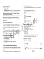
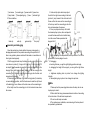
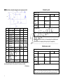
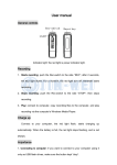
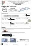
Content
Ⅰ.Brief introduction...................................1
II. Performance Summarize............................1
KD-202C Local examination lamp
III Main technical parameters...........................1
USER MANUAL
IV Security tips and symbol instructions................1
V Working Environment ...............................2
VI Product list.........................................2
V Product
interface..................................2
Ⅷ Assembly and debugging ...........................3
ⅨNote................................................4
Ⅹ Failure Judgment and Eliminating Methods..........4
Ⅺ Replacement of bulbs..............................4
Ⅻ After-sales service warranty ........................4
ⅩⅢTransportation and storage conditions..............4
Ⅹ Ⅳ Electrical schematic diagram and components
list. ..............................................7
9
Ⅰ.Brief introduction
Model:KD-202C
Scope of application:This product is a local auxiliary check lamp,
designed for doctors and nurses in diagnosis and treatment process
which demand higher for local lighting. It is mostly used in outpatient
visit and miniature operation occasion.
Characteristic: Small, can be bent freely, can be used together with
wall clip, ceiling clip, table clip and floor prop, wide serviceability.
Product component: Lamp holder, hose, power box, support parts
and power cord.
the specifications and requirements.
(2) The replacement of fuse protector should be the same with the
mark.
2. The introduction of the following symbols
Attention! Check the random documents
Protect the grounding
Disconnect the power
Connect the power
II. Performance Summarize:
The check lamp is designed with low voltage cold lighting system
and high power LED lighting source, safe and reliable. Lamp holder has
the function of curve transfer and rotating. Convenient, safe and
reliable.
The design and production of this light source strictly executes the
first part of the safety requirements of medical electrical equipment
GB4793.1-2007: general requirements which is guaranteed in safety.
III Main technical parameters:
Input voltage: 100V~245V 50HZ-60HZ
Lamp power: 3W 5W
Input power: ≤10W
Color temperature: 6000K±500K 4500K±500K
Fuse protector:2A
V Working Environment
A. Environmental temperature: -10℃~+40℃
B. Relative humidity : ≤75%
C. The atmosphere: 86.0~106.0kPa
VI Product list
Check lamp: one
power line: one
Fixture: ①table clip□ ②guide rail clip□ ③wall clip□
Floor prop: ①fixed floor prop□ ②lift floor prop
V Product
interface
1.Master device of KD-202C
IV Security tips and symbol instructions
1.When the check lamp is in use, you should always abide by the basic
safety precautions in order to avoid fire, electric shock or the risk of
injury,.
(1) Please read the instructions carefully, and operating according to
9
Picture1
①lock screw ②connecting pin ③power switch ④power box
⑧lamp holder ⑦flare-adjusting ring ⑥hose ⑤indicator light
2. Fixture interface
picture2
table clip
picture3
wall clip
picture4
guide rail clip
picture5
floor prop
Ⅷ Assembly and debugging
Open the packing box, check whether there are missing parts or
damage phenomenon of the products according to the product list. If
there is any problem, please contact with the dealer or manufacturer in
time to get solved properly.
1. Wall hung style check lamp: first determine the position of clip, size
is as shown in picture (2). Using a drill to dig four 10 mm holes with 25
mm depth. Plug the wooden stopper into the hole with a hammer, fix the
hanging fixture with tapping screws. Screw out the lock screw on the
connecting pin of the lamp, insert the connecting pin into the hole and
screw down the screws.
2. Table clip style check lamp: first install the clip (picture 3) in desktop
or mesa satisfying position, lock the fixed screw to make the clip firmed
in the desktop or mesa. Screw out the lock screw on the connecting pin
of the lamp, insert the connecting pin into the hole and screw down
the screws.
9
3. Guide rail clip style check lamp: adjust
the bolt to the right size according to the track
(picture 4), carry forward it into orbit and lock it.
Screw out the lock screw on the connecting pin
of the lamp, insert the connecting pin into the
hole and screw down the screws.
4. Floor prop style check lamp: first install
the chassis pulley in place, then contrapuntal
connect the base and the strut and the lamp.
Lock the screw. Please operate as the
diagram A.B.C.
A
B
E
Install according to the steps above, the lamp can work. Turn on the
power switch, the lamp begins to work.
5. Debugging:
a. bending the hose, you get the right lighting position and angle.
b. debugging the height of the support, you can get the right illume
height.
c. brightness adjusting knob in picture1 can change the lighting
intensity.
d. flare-adjusting ring in picture1 can change the spot size.
Ⅸ Note
1. Please pull out the power plug before clean the lamp, do not use
liquid spray to clean it.
2. When install the lamp, please assemble and reinforce it according
to the instruction of the technical requirements.
3. Do not use the lamp near water.
4. The maintenance, installation, commissioning of the lamp should
be operated by professional.
5. Never put any item on the power line.
6. The light intensity of illumination is higher, you should be cautious
in use with your eyes.
Ⅹ Failure Judgment and Eliminating Methods
Ⅺ Replacement of bulbs
The light bulb of this product is LED, normal life is of about 50000
hours. Generally there is no need to change. If there is any fault, please
inform the manufacturer to get appropriate treatment.
(It should be operated by the professionals)
Fault phenomena
Turn on the power
switch, the indicator is
not bright
Turn on the power
switch, the indicator is
bright but the lamp is
not bright
Fault cause
Power lines have no
electricity
The power cord is not
connected well
Fuse damage
Brightness adjusting
button is not open
Flare-adjusting ring is
not open
Bulb damage
System line fault
Other fault
9
Solution
Connect to the circuit
where there is
electricity supply
Reconnect the power
cord
Change the fuse
Transfer the
brightness adjusting
button to the
maximum
Transfer the
flare-adjusting ring to
the maximum
Contact with the
after-sale service
department for
solution
Contact with the
after-sale service
department for
solution
Contact with the
after-sale service
department for
solution
Ⅻ After-sales service warranty
Warranty of 18 months, provide maintenance service all user’s life.
◆In the warranty period, in normally using, the trouble because of
the product quality, the consumer depends on the warranty slip and
invoice enjoys free maintenance service.
◆If the error caused by refitted or install other functions which is
without our company’s permission, is not within the scope of
warranty.
◆If the model, number, release date is modified, deleted, moved or
unrecognized, will not enjoy the maintenance service.
◆The error caused by human factor such as falling, squeezing, dip
in, wetting, etc. is not within the scope of warranty.
◆Once receiving the goods, please sign and accept it after opening
the package to inspect and confirm whether the instrument is
crushed, scratched or not. Make sure there is no special
unnumbered inside. If the goods are damaged and you did not
inspect before sign it, It will be at your own risk.
ⅩⅢTransportation and storage conditions
A. Environmental temperature: -40℃~55℃
B. Relative humidity : ≤70%
C. The atmosphere: 50Kpa~106Kpa
Warranty card
ⅩⅣElectrical schematic diagram and components list
Company name:
Address
Product
name
Serial
Number
Sale date
N0.
1
2
3
4
5
6
Material name Specification Quantity Remark
Circuit board
1
Bilateral diode DB3
1
Resistance
2.4K/0.25W
1
Resistance
39Ω /0.25W
1
Resistance
47K/0.25W
1
Resistance
100Ω /0.25W
1
Adjustable
2K
1
7
resistance
Capacitance
8
100nf/400V
2
Capacitance
9
473J/630V
1
Power
30W
1
10
transformer
Silicon
BTA06D
1
11
controlled
Fuse
F2A-L250
1
12
Any products may be updated or improved. The change of circuit or
element specifications of the product will not with prior notice.
2012 edition
Phone No.
Model
Manufacture
date
Fault description:
Remark: The warranty of our products is 18 months since the release
date.
(Please truthfully fill in this form, cut it according to the dotted line and
send it back to our company, thank you for your cooperation)
┄┄┄┄┄┄┄┄┄┄┄┄┄┄┄┄┄┄┄┄┄┄┄┄┄┄┄┄┄┄┄
Maintenance card
Company name:
Address
Product
name
Serial
Number
Sale date
Phone No.
Model
Manufacture
date
Fault description:
Remark: You can enjoy seventy percent discount for the maintenance
services even if you use this card over the quality assurance period.
9