1
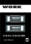
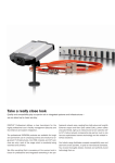
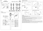
µBEEP
USER MANUAL
Microgate s.r.l.
Via J. Kravogl, 8
39100 BOLZANO
ITALIA
µBeep User Manual
Doc: MGA-µB1998-001
Version: 1.0
Page 2 of 11
INDEX
DESCRIPTION................................................................................................................................................................. 3
CONNECTIONS............................................................................................................................................................... 5
HOW TO USE µBEEP..................................................................................................................................................... 6
FUNCTION MODES ....................................................................................................................................................... 6
SELECTION OF CYCLE TIME ................................................................................................................................. 10
OUTPUTS TOWARDS THE CHRONOMETER ....................................................................................................... 11
THE LCK (LOCK) KEY ............................................................................................................................................... 11
BATTERY RECHARGE ............................................................................................................................................... 11
Doc: MGA-µB1998-001
Version: 1.0
Page 3 of 11
µBeep User Manual
Description
1
14
2
3
4
13
12
5
11
6
7
10
9
8
1. Alphanumeric display 2 lines x 16 characters
2. LAP output
3. GND
4. START output (end of cycle)
5. LCK key (Activates/Disactivates outputs: Beeper and signal lights)
6. ENTER key ( to put into effect modifications and selections)
7. DOWN ARROW key
8. UP ARROW key
9. GND
10. Photocell input
11. Red LED (Synchronized with Red light signal output)
12. Yellow LED (Synchronized with Yellow light signal output)
13. Green LED (Synchronized with Green light signal output)
14. 6 pole Amphenol socket for connection to signal lights
µBeep User Manual
Doc: MGA-µB1998-001
Version: 1.0
Page 4 of 11
1
2
1. BATTERY RECHARGE JACK input ( Vin= 9÷18V)
2. ON/OFF switch
µBeep User Manual
Doc: MGA-µB1998-001
Version: 1.0
Page 5 of 11
Connections
Photocell
Beeper
Chronometer
Signal lights
µBeep User Manual
Doc: MGA-µB1998-001
Version: 1.0
Page 6 of 11
How to use µBeep
As soon as it is switched on the beeper sets itself to a base configuration (Alpine Skiing with a cycle
time of 20 seconds) with all the outputs de-activated, the 3 LEDs on and the time counter blocked.
From this configuration it is possible to set a mode of use suitable for the race to be managed and an
appropriate cycle time.
An arrow ‘→’ appears on the left of the display. If the arrow is on the first line, pressing ENTER
will take you to the selection of function mode, if the arrow is on the second line, to the selection of
cycle time. The arrow can be moved from one line to the other with the “Up Arrow”, “Down
Arrow” keys.
Function modes:
The current program has the following function modes:
MODE 1
Name : Alpine Skiing
Explanation line: “-10R -5G -3<V<3”
Available cycle times:
20s
30s
40s
45s
1 min
1 min 30s
2 min
2 min 30s
This mode emits a long BOOP at -10s from the start with the red light coming on, at –5 countdown
begins with a BIP every second and the yellow light coming on, at –3 the green light comes on
UNTIL +3.
At the end of every cycle an impulse is given on the START output.
Time
Beeper
Lights
-10
-5
-4
-3
-2
-1
0
+3
Long BOOP
BIP
BIP
BIP
BIP
BIP
BIP
RED
YELLOW YELLOW GREEN GREEN GREEN GREEN OFF
MODE 2
Name : Cross-country skiing
Explanation line: "Green from -5 to +5"
Available cycle times :
20s
45s
2 min
30s
1 min
2 min 30s
40s
1 min 30s
This mode emits a long BOOP at -10s from the start, at –5 countdown begins with a BIP every
second and the green light coming on UNTIL +5.
Doc: MGA-µB1998-001
Version: 1.0
Page 7 of 11
µBeep User Manual
At the end of every cycle an impulse is given on the START output.
Time
Beeper
-10
Long BOOP
-5
BIP
-4
BIP
-3
BIP
-2
BIP
-1
BIP
Lights
OFF
GREEN
GREEN
GREEN
GREEN
0
BIP
+5
GREEN GREEN OFF
MODE 3
Name : Rally 0
Explanation line : "-10R -5GP 0<V<+5"
Available cycle times :
20s
45s
30s
1 min
40s
1 min 30s
2 min
2 min 30s
This mode turns on the red light at -10s from the start, at -5 countdown begins with the yellow light
coming on and every second a pixel going off;
At the end of the cycle the green light comes on UNTIL +5 and an impulse is given on the START
output.
Time
Beeper
Lights
-10
OFF
RED
-5
OFF
YELLOW
+
PIXEL
-4
OFF
YELLOW
+
PIXEL
-3
OFF
YELLOW
+
PIXEL
-2
OFF
YELLOW
+
PIXEL
-1
0
+5
OFF
BIP
OFF
YELLOW GREEN GREEN
+
PIXEL
MODE 4
Name : Rally 1
Explanation line : "-10R -5G 0<V<+9"
Available cycle times :
20s
45s
30s
1 min
40s
1 min 30s
2 min
2 min 30s
This mode turns on the red light at –10s from the start, at -5 the yellow light comes on.
At the end of the cycle the green light comes on UNTIL +9 and gives an impulse on the START
output.
Time
Beeper
Lights
-10
OFF
RED
-5
OFF
YELLOW
-4
OFF
YELLOW
-3
OFF
YELLOW
-2
OFF
YELLOW
-1
0
+9
OFF
BIP
OFF
YELLOW GREEN GREEN
µBeep User Manual
Doc: MGA-µB1998-001
Version: 1.0
Page 8 of 11
MODO 5
Name : Rally 2
Explanation line : "-10G -3V +3R "
Available cycle times :
20s
30s
40s
45s
1 min
1 min 30s
2 min
2 min 30s
This mode turns on the yellow light at –10s from the start, at -3 the green light comes on and at +3
the red light comes on and remains on until the next –10.
At the end of the cycle it gives an impulse on the START output.
Time
Beeper
Lights
-10
OFF
YELLOW
-3
OFF
GREEN
0
BIP
GREEN
+3
OFF
RED
MODE 6
Name : Rally 3
Explanation line : "-10R -5GP 0<V<+20"
Available cycle times :
45s
30s
1 min
40s
1 min 30s
2 min
2 min 30s
This mode turns on the red light at –10s from the start, at -5 the yellow light comes on when
countdown begins and a pixel goes off every second.
At the end of the cycle the green light comes on UNTIL +20 and gives an impulse on the START
output
Time
Beeper
Lights
-10
OFF
RED
-5
OFF
YELLOW
+
PIXEL
-4
OFF
YELLOW
+
PIXEL
-3
OFF
YELLOW
+
PIXEL
-2
OFF
YELLOW
+
PIXEL
-1
0
+20
OFF
BIP
OFF
YELLOW GREEN GREEN
+
PIXEL
MODE 7
Name : Rally 4
Explanation line : "-10R -5GP 0<V<+20"
Available cycle times :
45s
30s
1 min
40s
1 min 30s
2 min
2 min 30s
µBeep User Manual
Doc: MGA-µB1998-001
Version: 1.0
Page 9 of 11
This mode turns on the red light at -10s from the start, at –5 the yellow light comes on.
At the end of the cycle the green light comes on UNTIL +10 and gives an impulse on the START
output.
Time
Beeper
Lights
-10
OFF
RED
-5
OFF
YELLOW
-4
OFF
YELLOW
-3
OFF
YELLOW
-2
OFF
YELLOW
-1
0
+10
OFF
BIP
OFF
YELLOW GREEN GREEN
MODE 8
Name : User
Explanation line : Autodefined
Available cycle times : according to the sequence set
This mode allows the user to construct with complete freedom an on/off sequence for signal lights
and sounds inserted within a cycle time.
The sequence is constructed by selecting in succession:
• event time : the beginning/end of the cycle is indicated by T=0. With the arrows the time value
is increased or decreased within a range of variability from –127 to +127.
• type of sound : the following options are possible
1. Silent
2. Bip
3. Boop
4. Long bip
5. Long boop
• type of signal light : the following options are possible
1. Off
2. Red
3. Yellow
4. Green
5. Pixel
6. Yellow+Pixel
The signal light options set for the instant of time are kept until the value of the next event time
selection. The device sets the insertion of the beeper and signal light values for the instant T=0.
On the basis of the value limits of the sequence set, the system then determines the minimum value
permitted for the cycle time. Subsequently the user must select the cycle time from the values
suggested by the device.
Doc: MGA-µB1998-001
Version: 1.0
Page 10 of 11
µBeep User Manual
Example:
The user wishes to construct the following sequence:
-10
-5
Time
OFF
BOOP
Beeper
RED
YELLOW
Lights
with a cycle time of 30 seconds
-1
OFF
GREEN
+5
OFF
OFF
The user must insert the data in the following way:
Time
Beeper
Lights
-10
SILENT
RED
-5
BOOP
YELLOW
-4
SILENT
YELLOW
-1
SILENT
GREEN
0
SILENT
GREEN
+5
SILENT
OFF
Selection of the time cycle
After choosing a function mode or directly selecting time cycle selection from the main menu, the
user must choose the repetition time of the sequence currently set.
For each function mode only those times consistent with the choice entered are presented.
The up and down arrows are used for selection of the time required; when the desired time has been
set, press ‘ENTER’ for confirmation.
Bear in mind that the insertion of an event time with the relative sound and color characteristics
mean the “employment ” of a second. The settings chosen are attributed to a minimum time unit of
one second. This characteristic must be kept in mind in the calculation of the minimum duration of
the cycle.
Example
Time
Beeper
Lights
-10
SILENT
RED
0
BIP
GREEN
In this situation the minimum duration of the cycle is 11 seconds.
-10
-9
1 Sec
0
9 Sec
1 Sec
Minimum T of cycle = 11 seconds
1
µBeep User Manual
Doc: MGA-µB1998-001
Version: 1.0
Page 11 of 11
Outputs towards the chronometer
There are two different modes of operation :
Photocell always active
In this mode in the case of a false start the photocell impulse is transmitted to the START
output of the beeper at any moment of the sequence, while the following end of cycle
impulse is transmitted to the LAP output of the Beeper.
Analysis of the impulses on the start chronometer makes it possible to detect false starts and
times which deviate from the official start.
Active photocell only with yellow signal light active
In this mode the photocell impulses are only retransmitted to the chronometer if they have
been emitted after the yellow signal light has come on. Also in this case false starts are
transmitted to the START output of the beeper whereas the subsequent end of cycle impulse
is transmitted to the LAP output of the Beeper.
Analysis of the impulses on the start chronometer makes it possible to detect false starts and
times which deviate from the official start.
When one of the Rally modes is selected the user must select one of the two work modes.
The LCK (Lock) key
The LCK key makes it possible to disactivate the outputs without losing synchronization of the
cycle time.
When the key is pressed, the letters “LK” appear at the top right of the display to signal the status of
the system.
When the Lock is disactivated, the outputs (Beep and Signal Light Set) will be activated for the next
cycle sequence. When the outputs block is active the indicator LEDs are still lit to give an idea of
the current situation of the sequence.
Battery recharge
To recharge the batteries simply insert a power supply tension between 11 and 18V in the
appropriate jack (see fig3). The complete recharge cycle lasts 8 hours.
When the batteries are low, this is signaled on the display by the appearance of a “B” in the bottom
right corner of the display.
The device can also function with an external power source once more using the recharge jack with
tensions of between 11 and 18V.