1
OPERATOR'S MANUAL
THD SATELLITE COMPASS
MODEL
SC-50
www.furuno.co.jp
The paper used in this manual
is elemental chlorine free.
・FURUNO Authorized Distributor/Dealer
9-52 Ashihara-cho,
Nishinomiya, 662-8580, JAPAN
Telephone : +81-(0)798-65-2111
Fax
: +81-(0)798-65-4200
All rights reserved.
Printed in Japan
A : FEB . 2004
C3 : OCT . 31, 2008
Pub. No. OME-72510-C3
(TATA )
SC-50
*00014854812*
*00014854812*
* 0 0 0 1 4 8 5 4 8 1 2 *
SAFETY INSTRUCTIONS
Safety Instructions for the Operator
WARNING
ELECTRICAL SHOCK HAZARD
Safety Instructions for the Installer
WARNING
Do not open the equipment.
Turn off the power at the switchboard
before beginning the installation.
Only qualified personnel
should work inside the
equipment.
Fire or electrical shock can result if the
power is left on.
Do not disassemble or modify the
equipment.
Fire, electrical shock or serious injury can
result.
Immediately turn off the power at the
switchboard if the equipment is emitting
smoke or fire.
Continued use can cause fatal damage to
the equipment. Contact a FURUNO agent
for service.
Do not place liquid-filled containers on
the top of the processor unit.
Fire or electrical shock may result if the
liquid enters the equipment.
Use the proper fuse.
Use of a wrong fuse can damage the
equipment and cause fire.
CAUTION
No one navigation device should ever
be solely replied upon for the navigation
of a vessel.
Do not install the equipment where it
may get wet from rain or water splash.
Water in the equipment can cause fire,
electrical shock or damage to the equipment.
NOTICE
Observe the following compass safe
distances to prevent interference to a
magnetic compass:
Display unit
SC-502
Processor unit
SC-501
Antenna unit
SC-303
Antenna unit
SC-603
Standard
Compass
Steering
Compass
0.4 m
0.3 m
0.9 m
0.55 m
0.3 m
0.3 m
0.3 m
0.3 m
WARNING LABEL
A warning label is attached to the
processor unit. Do not remove the label.
If the label is missing or damaged,
contact a FURUNO agent or dealer
about replacement.
WARNING
Always confirm position against all available aids to navigation (incl. nautical charts),
for safety of vessel and crew.
To avoid electrical shock, do not
remove cover. No user-serviceable
parts inside.
WARNING LABEL
Name:
Warning Label (1)
Type:
86-003-1011-1
Code No.: 100-236-231
i
TABLE OF CONTENTS
FOREWORD ..................................................................................................................iv
SYSTEM CONFIGURATION ...........................................................................................v
EQUIPMENT LIST..........................................................................................................vi
SPECIFICATIONS .....................................................................................................SP-1
1 INSTALLATION ...................................................................................................... 1-1
1.1
1.2
1.3
1.4
1.5
1.6
1.7
Mounting Considerations..................................................................................................... 1-1
1.1.1 Antenna unit............................................................................................................. 1-1
1.1.2 Display unit, processor unit...................................................................................... 1-3
Installing the Antenna Unit................................................................................................... 1-4
1.2.1 Antenna unit SC-303 ............................................................................................... 1-4
1.2.2 Antenna unit SC-603 ............................................................................................... 1-7
Installing the Processor Unit.............................................................................................. 1-12
1.3.1 Bulkhead mount ..................................................................................................... 1-12
1.3.2 Deck mount............................................................................................................ 1-13
1.3.3 Installation on the underside of a desk .................................................................. 1-14
Installing the Display Unit .................................................................................................. 1-15
1.4.1 Desktop, overhead mounting................................................................................. 1-15
1.4.2 Flush mount ........................................................................................................... 1-15
Wiring................................................................................................................................. 1-17
Initial Settings .................................................................................................................... 1-20
1.6.1 Confirming satellite status...................................................................................... 1-20
1.6.2 Choosing mounting method................................................................................... 1-21
Connection of External Equipment.................................................................................... 1-22
1.7.1 General wiring........................................................................................................ 1-22
1.7.2 Fabrication of cables.............................................................................................. 1-23
2 OPERATION........................................................................................................... 2-1
2.1
2.2
2.3
2.4
2.5
2.6
2.7
2.8
2.9
ii
Controls................................................................................................................................ 2-1
Turning the Power On/Off.................................................................................................... 2-2
Panel Illumination, Display Contrast.................................................................................... 2-2
Choosing a Display.............................................................................................................. 2-3
2.4.1 Description of displays............................................................................................. 2-3
Alarm Setup ......................................................................................................................... 2-6
Confirming Satellite Status .................................................................................................. 2-7
GPS Setup ........................................................................................................................... 2-8
2.7.1 Displaying the GPS setup menu.............................................................................. 2-8
2.7.2 GPS SETUP menu description................................................................................ 2-8
Output Data.......................................................................................................................... 2-9
2.8.1 Heading.................................................................................................................... 2-9
2.8.2 Log pulse ............................................................................................................... 2-13
System Setup .................................................................................................................... 2-14
2.9.1 Geodetic data......................................................................................................... 2-14
2.9.2 Units of measurement............................................................................................ 2-15
2.9.3 Using local time...................................................................................................... 2-15
2.10
2.11
2.12
2.13
2.14
2.9.4 Time format ..........................................................................................................2-15
2.9.5 Demonstration mode ............................................................................................2-16
WAAS/DGPS Setup .........................................................................................................2-17
OTHERS Menu ................................................................................................................2-19
TRIP Menu .......................................................................................................................2-20
Resetting Distance Run ...................................................................................................2-21
Choosing External Heading Source for Backup ...............................................................2-21
3 MAINTENANCE, TROUBLESHOOTING................................................................3-1
3.1
3.2
3.3
3.4
3.5
3.6
3.7
3.8
Preventive Maintenance.....................................................................................................3-1
Troubleshooting .................................................................................................................3-2
Diagnostics ........................................................................................................................3-3
Program Number................................................................................................................3-7
Clearing Data .....................................................................................................................3-7
Replacement of Battery......................................................................................................3-8
Replacement of Fuse .........................................................................................................3-9
Error Messages..................................................................................................................3-9
APPENDIX ................................................................................................................AP-1
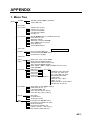
1. Menu Tree............................................................................................................................AP-1
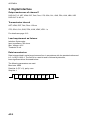
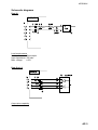
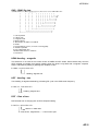
2. Digital Interface ....................................................................................................................AP-2
3. Input/Output Ports................................................................................................................AP-8
4. Parts List and Parts Location .............................................................................................AP-10
5. Geodetic Chart Codes .......................................................................................................AP-12
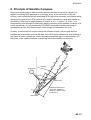
6. Principle of Satellite Compass ...........................................................................................AP-13
7. What is WAAS? .................................................................................................................AP-14
PACKING LIST
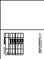
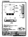
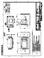
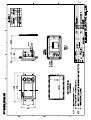
OUTLINE DRAWINGS
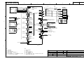
INTERCONNECTION DIAGRAM
INDEX ........................................................................................................................ IN-1
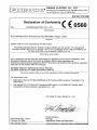
Declaration of Conformity
iii
FOREWORD
A Word to the Owner of the SC-50
FURUNO Electric Company thanks you for purchasing the FURUNO SC-50
THD Satellite Compass. (Hereafter, for sake of brevity, we refer to the SC-50 as
Satellite Compass.) We are confident you will discover why the FURUNO name
has become synonymous with quality and reliability.
For 60 years FURUNO Electric Company has enjoyed an enviable reputation for
quality and reliability throughout the world. This dedication to excellence is
furthered by our extensive global network of agents and dealers.
Your satellite compass is designed and constructed to meet the rigorous
demands of the marine environment. However, no machine can perform its
intended function unless properly installed and maintained. Please carefully read
and follow the operation, installation and maintenance procedures set forth in
this manual.
We would appreciate feedback from you, the end-user, about whether we are
achieving our purposes.
Thank you for considering and purchasing FURUNO.
Features
The SC-50 is a new satellite compass designed with FURUNO’s advanced GPS
kinematic technology. This compass finds a wide range of applications for any
type of ships and mobile units at sea or on land.
The main features are
• Perfect for use as heading sensor for Radar/ARPA, AIS, ECDIS, scanning
sonar
• There are no mechanical parts such as gimbals or rotating motor, thus the
compass is free from routine maintenance
• The performance is not affected by geomagnetism thus it is suitable for use on
any vessel
• No need for speed correction like a gyrocompass
• Short settling time - three minutes
• Meets the following requirements: IMO MSC. 116(73), ISO/FDIS 22090-3,
IMO A. 694(17), IEC 60945 (2002-08), IEC 61162 (2000).
iv
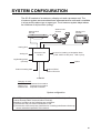
SYSTEM CONFIGURATION
The SC-50 consists of an antenna, a display unit and a processor unit. The
tri-antenna system accommodates three antennas/receiver units and is available
in a low-profile radome type or open type. The tri-antenna system helps reduce
the influence of ship's motion (rolling).
Antenna Unit
SC-603
Antenna Unit
SC-303
Display Unit
SC-502
OR
2
3
Analog pitch
Analog roll
6 ports for Heading or Navigation Data
(5 AD-10/IEC 61162 ports, 1 AD-10 port)
Processor Unit
SC-501
Log/Heading alarm
(Contact)
: Option
External heading data
External DPGS
Beacon Receiver
12-24 VDC
Category of Units
Processor Unit:Protected from weather
Display Unit: Protected from weather
Antenna Unit: Exposed to weather
System configuration
This GPS receiver complies with Canadian standard RSS-210 (Low Power
License-Exempt Radio communication Devices).
Operation is subject to the following two conditions:
(1) this device may not cause interference, and
(2) this device must accept any interference, including interference that may
cause undesired operation of the device.
v
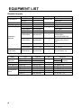
EQUIPMENT LIST
Standard supply
Name
GPS Antenna
Display Unit
Processor Unit
Installation
Materials
Spare Parts
Type
SC-303
SC-603
SC-502
SC-501
CP20-02230*
CP20-02260*
CP20-02231*
Code No.
004-378-110
004-379-660
004-378-050
Qty
CP20-02600
000-041-905
1
CP20-02203*
004-380-660
1
CP20-02201*
004-377-570
1
Antenna base for SC-603
CP20-02202*
004-377-590
1
For SC-603
SP20-01101*
004-379-720
1
For processor unit
Code No.
004-372-110
004-372-120
000-143-559
000-041-405
000-040-720
004-380-820
004-380-830
004-380-840
Qty
Choose one
Remarks
Radome type
Open type
1
1
1
1
TPPX cable
TNC cable
For SC-303
For processor unit:
CP20-02601*,
MJ-A7SPF0006-100
For display unit:
Tapping screw (5X20 4
pcs.)
Optional supply
Name
Antenna
Cable Set
Cable Assy.
Flush Mount F
Flush Mount S
Bird-repellent
fixture
Type
CP20-01700
CP20-01710
TPPX6-3D2V-15M
OP20-29*
OP20-17*
OP20-35
OP20-36
OP20-37
* See packing list at back of manual.
vi
1
1
1
1
1
1
1
Remarks
30 m
3 sets
required
50 m
Antenna cable
For display unit
For display unit
For SC-303, 9 pcs.
For SC-603, 4 pcs.
For SC-603, 1 pc.
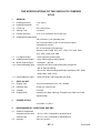
THD SPECIFICATIONS OF THD SATELLITE COMPASS
SC-50
1
GENERAL
1.1
Heading Accuracy
±1.0° (95%)
1.2
Heading Resolution
0.1°
1.3
Follow-up
45°/s rate-of-turn
1.4
Settling Time
3 minutes
1.5
Position Accuracy
10 m, or 5 m (DGPS), 95% of the time
1.6
Heading/Nav Data Output
AD-10 format: 1 port (specialty port)
AD-10 format 5 ports or IEC 61162 format 10 ports
(selectable on menu)
IEC 61162 format is RS-485 level
Sentence: HDT, HDM, ROT, ATT, VDR, VTG, GGA, GNS
GLL, VHW, VBW, HVE, ZDA
1.7
Log Signal Output
1 port, log pulse (pulse signal)
1.8
Heading Alarm Output
1 port, alarm output (contact signal)
1.9
Motion Output Signal
1 port pitch, 1 port roll
1.10 External Heading Input
1 port AD-10 or IEC61162 format (auto recognition)
‐AD-10: backup heading
‐IEC 61162: water tracking speed input (sentence: HDT, HDG,
HDM, VBW, VHW, VLW)
1.11 External Beacon Input
1 port, RTCM SC-104 format (RS-232 level)
2
DISPLAY UNIT
2.1
Display Type
4.5 inch monochrome LCD, 120 x 64 dots
2.2
Effective Area
60 mm (H) x 95 mm (W)
2.3
Contrast
64 levels
2.4
Display Mode
Heading, Nav data, Steering, Compass rose, Rate of turn and
Speed modes
3
POWER SUPPLY
12-24 VDC: 1.2-0.5 A
4
ENVIRONMENTAL CONDITIONS AND EMC
4.1
Ambient Temperature
4.2
Display/Processor Unit
-15°C to +55°C, Designed for protected area
Antenna Unit
-25°C to +70°C, Designed for exposed area
Humidity
93% ±3% at 40°C
SP - 1
E7251S01B
4.3
Waterproofing
Antenna Unit
IPX6
Display Unit
IPX5
Processor Unit
IPX0
4.4
Vibration
IEC 60945
5
COATING COLOR
5.1
Display/Processor Unit
Panel: N3.0 Newtone No.5 (dark gray)
Chassis: 2.5GY5/1.5 (light gray)
5.2
Antenna Unit
N9.5 (white)
SP - 2
E7251S01B
1
INSTALLATION
1.1
Mounting Considerations
1.1.1
Antenna unit
General
• Keep the length of the antenna cable in mind when selecting a mounting
location.
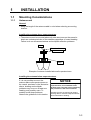
Installing the antenna above superstructures
• The antenna must be mounted above all other structures on the vessel to
obtain an unobstructed view of the satellites regardless of vessel heading.
Failure to do so will cause shadows and multipath reflection problems.
Mast
SC-series Antenna
Radar Antenna
Bridge
Example of antenna installed above all superstructures
Installing the antenna below superstructures
If it is not possible to mount the
antenna above all superstructures on
the vessel, as shown in the illustration
above, shading and multipath
problems may occur on at least one
heading, and possibly more. To
possibly avoid those problems,
observe the guidelines in this section.
NOTICE
If the antenna is installed below any
superstructure, the installation must
be done over a two-day period, following
the procedure in the service manual.
At least 12 hours are required to capture
tracking data to measure multipath indexes
and locate areas of shading.
1-1
1. INSTALLATION
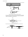
• The horizontal separation between the antenna and masts must be as follows:
Mast diameter
10 cm
30 cm
Separation distance (minimum)
1.5 m
3m
SC-50’s
antenna
Horizontal
separation
distance
Mast, etc.
Mast, etc.
Less than 10°
TOP VIEW
Horizontal separation between antenna and masts
• The field of view above the antenna should be as shown below, ±80° against
zenith. To avoid reflections from masts and the like, locate the antenna well
away from the shadows of the radar mast, etc.
Zenith
-80° +80°
SC-series antenna
SIDE VIEW
Antenna and field of view
• Locate the antenna unit above the radar antenna, out of the radar beam.
SC-series Antenna
Radar Antenna
1-2
1. INSTALLATION
Location influenced
by reflected wave.
Radar Antenna
SC-series
Antenna
Reception blocked by mast.
Bridge
Example of antenna installed below superstructures
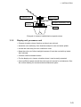
1.1.2
Display unit, processor unit
• Choose a location where vibration and shock are minimal.
• Install the units well away from locations subject to rain and water splash.
• Locate the units away from air conditioner vents.
• Keep the units out of direct sunlight because of heat that can build up inside
their cabinets.
• Choose a well-ventilated location.
• For the display unit, choose a location where it can be easily operated.
• Leave sufficient space around the units to permit access for maintenance. See
the outline drawing for recommended maintenance space.
1-3
1. INSTALLATION
1.2
Installing the Antenna Unit
1.2.1
Antenna unit SC-303
Note: “Bird-repellent fixtures” (supplied) may be attached to the antenna cover to
prevent birds from alighting on the cover. If it is more convenient to attach
them before fixing the antenna unit to the mounting location, do step 9
before fixing the antenna unit.
NOTICE
Fasten the antenna to the mounting
location lastly if it is more convenient
to connect the antenna cable before
mounting the antenna unit.
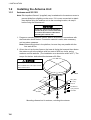
1. Prepare a mounting platform (wood, steel or aluminum) in accordance with
the illustration shown below. If corrosive material is used, take necessary
anti-corrosion measures.
Note: When drilling holes in the platform, be sure they are parallel with the
fore-and-aft line.
2. Orient the unit so the two lines on the base is facing the bow and then fasten
the antenna unit to the platform with four sets of M10 hex. bolts, spring
washers and flat washers. (The installation error should be within ±2.5°.) The
torque for the hex. bolts should be between ±20 2Nm.
NOTICE
Do not open the antenna.
This installation does not require removal
of the antenna cover.
N
U
R
F
U
BOW
240
160
Fixing Hole
(f11 mm)
5-10 mm
Flat Washer
160
240
Mounting dimensions for antenna, orienting the antenna
1-4
Spring Washer
Hex. Bolt
1. INSTALLATION
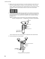
3. Coat exposed parts of nuts, bolts and washers with silicone sealant.
Radome
base
Platform
Coat with
silicone sealant.
Coating bolt, nut and washers with silicone sealant
4. Connect the three coaxial cables coming from the antenna unit to the
appropriate coaxial cables on the antenna cable, referring to the table below.
Cable from antenna
(no. marked on cable)
ANT 1
ANT 2
ANT 3
Cable
TTPX6-3D2V-15M
No color
Yellow
Red
For TNC-PS-3D-15, cable labels are provided from cable 1, 2 and 3 to
differentiate between then.
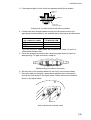
5. Cover the antenna connectors with vulcanizing tape and vinyl tape, for
waterproofing. Tie tape ends with a cable tie.
Waterproofing the antenna connector
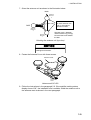
6. Set the joints of the coaxial cables into the cavity in the antenna base.
7. Pass two cable ties (long life, temperature resistant type, local supply)
through the hole shown in the figure below. Fasten them at the locations
shown in the figure below.
Cable Tie
How to fasten the antenna cable
1-5
1. INSTALLATION
8. Set the “cable cover” to the antenna base as shown in the figure below.
Cable Cover
How to insert the cable cover
HOW TO REMOVE CABLE COVER
Insert slotted-head
screwdriver here to
remove cable cover.
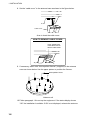
9. If necessary, attach nine “bird-repellent fixtures” (supplied) to the antenna
cover as shown below. Use the paper pattern to position the fixtures.
Bird-repellent fixture
N
U
R
F
U
Antenna unit
10. Follow paragraph 1.6 to set up the equipment. If the status display shows
“OK” the installation Is suitable. If OK is not displayed, relocate the antenna.
1-6
1. INSTALLATION
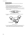
1.2.2
Antenna unit SC-603
Note: “Bird-repellent fixtures” (supplied) may be attached to each antenna
element and the Antenna Cover to prevent birds from alighting on the
antenna. If it is more convenient to attach them before fixing the antenna
unit to the mounting location, do step 10 in “Welding the antenna unit”
before fixing the antenna unit.
Mounting
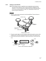
1. Screw in three antenna elements in the Antenna Base. Remove Antenna
Cover and Arm Cover.
Antenna Cover
2
Antenna
Element
3
Arm Cover
(Below arm)
Antenna Base
1
Antenna unit SC-603
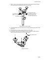
2. Pass the coaxial cable from each antenna element through the center of the
respective arm and then through the hole at the center of the antenna unit.
3. Orient the three antenna elements so that the protrusion on each faces the
bow.
BOW
Nut
Orient the three antenna
elements so the protrusion
on each faces the bow.
Arm Cover S
How to orient the antenna elements
1-7
1. INSTALLATION
4. Making sure each antenna element is correctly oriented, fix each with its nut.
Write the corresponding arm number on each coaxial cable, using a magic
marker. (When connecting with the coaxial cables from the processor unit it is
necessary to match correct antenna element number with coaxial cable
color.)
Arm [1]
1
Arm [2]
2
Arm [3]
3
5. Temporarily fix the pedestal and support plate to the antenna mast as shown
in the illustration below. (The pedestal and support plate will be welded to the
antenna mast after confirming that the installation site is suitable, following
paragraph 2.6.)
Note: If U-bolts are used to temporarily fix the pedestal and support plate,
DO NOT overtighten them – overtightening may deform the pedestal.
BOW
PEDESTAL
Clamp
Support Plate
Antenna Mast
(Local supply
(f50 mm or more)
How to temporarily fix the support plate and pedestal to the antenna mast
6. Set the antenna unit to the pedestal.
2
3
1
Coaxial Cable Identification
Arm [1]: 1
Arm [2]: 2
Arm [3]: 3
Flat Washer
Spring Washer
Nut
Fixing antenna unit to pedestal
1-8
1. INSTALLATION
7. Orient the antenna unit as shown in the illustration below.
BOW
Antenna
Element
2
A number is inscribed
on each antenna arm.
This is the antenna
element number.
PORT
Antenna
Element
3
The bow mark is between
antenna element [1] and [2].
Face the bow mark towards
the bow
Antenna
Element
1
Orienting the antenna unit (top view)
NOTICE
The antenna unit should be positioned
within ±2.5° of the bow.
8. Fasten the Antenna Cover with three screws.
Antenna Cover
2
3
1
Antenna unit SC-603
9. Follow the instructions in the paragraph 2.6. If the satellite tracking status
display shows “OK,” the installation site is suitable. Weld the antenna unit to
the antenna mast as shown in the next paragraph.
1-9
1. INSTALLATION
Welding the antenna unit
The antenna unit may be welded to the antenna mast if the satellite status
display shows “OK.”
1. Unfasten the coaxial cables and dismount the antenna unit.
2. Weld the pedestal and support plate to the antenna mast. Remove the
clamps used to temporarily fasten the pedestal and support plate.
3. Fasten the coaxial cables and fix the antenna unit.
4. Wrap the antenna connector with self-vulcanizing tape and then vinyl tape for
waterproofing as shown in the illustration below. Tie tape ends with cable ties
to prevent unraveling.
Waterproofing the antenna connector
5. Coat the three screws fixing the Antenna Cover S with Three Bond 1211
(supplied).
2
3
Coat screws with
ThreeBond (supplied).
1
Antenna unit SC-603
6. Look at the heading indication on the display. If the heading error is between
5° and 10°, loosen the nut at the center of the antenna unit and adjust
antenna orientation, while watching the heading indication on the display.
1-10
1. INSTALLATION
7. Make a loop in the antenna cable as shown in the illustration below. Fasten
the antenna cable to the antenna mast with cable ties.
Coat bolt threads with
Three Bond. Fasten bolt
with nuts and then coat
nuts with Three Bond also.
Coat with Three
Bond 1211 (supplied).
Fix antenna cable.
Fastening the antenna cable
8. Coat bolt threads and nuts at the bottom of each antenna element with Three
Bond 1211.
9. Paint pedestal and support plate with anti-corrosive paint.
10. If necessary, attach the “bird-repellent fixtures” (supplied) to each antenna
element and the Antenna Cover S as shown below.
Bird-repellent fixture
Antenna element
1-11
1. INSTALLATION
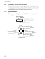
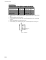
1.3
Installing the Processor Unit
The processor unit should be mounted aligned with the ship’s fore-and-aft line. It
can be mounted on the deck, bulkhead, or on the underside of a desk. Choose a
mounting location which allows you to easily view the power lamp on the top of
the unit and which is within ±2.5° of the ship’s fore-and-aft line.
1.3.1
Bulkhead mount
The processor unit is shipped from the factory ready for bulkhead mounting.
Orient the processor unit as shown below and fix it to the mounting location with
four tapping screws (M5x20). You will set the orientation later on the menu.
Reference Direction
Bulkhead
Mount processor unit so
reference direction is within
±2.5° of fore-and-aft line.
Name Plate (other side)
Direction
A
Direction D
Mounting Method: "Wall"
(Bulkhead)
Mounting Direction: D
Mounting Method: "Wall"
(Bulkhead)
Mounting Direction: A
Direction B
Direction
C
Mounting Method: "Wall"
(Bulkhead)
Mounting Direction: B
Mounting Method: "Wall"
(Bulkhead)
Mounting Direction: C
Bulkhead mount
1-12
1. INSTALLATION
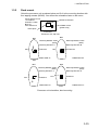
1.3.2
Deck mount
Orient the processor unit as shown below and fix it to the mounting location with
four tapping screws (M5x20). You will set the orientation later on the menu.
Mount processor unit
so reference
direction is within
±2.5° of
fore-and-aft line.
Reference Direction
POWER switch
(power lamp)
Name plate
Connectors
Processor Unit, top view
Bow
Bow
Mounting Method: "Floor"
(Deck)
Mounting Direction: B
Mounting Method: "Floor"
(Deck)
Mounting Direction: A
Starboard
Port
Starboard
Port
DIRECTION "A"
DIRECTION "B"
Stern
Stern
Bow
Bow
Mounting Method: "Floor"
(Deck)
Mounting Direction: C
Port
Starboard
Mounting Method: "Floor"
(Deck)
Mounting Direction: D
Starboard
Port
DIRECTION "C"
Stern
DIRECTION "D"
Stern
Processor unit orientation, deck mounting
1-13
1. INSTALLATION
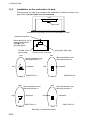
1.3.3
Installation on the underside of a desk
The processor unit may be mounted on the underside of a desk as shown in the
figure below. Do not install it on the overhead.
Desk
Name Plate
Installation of processor unit on the underside of a desk
Reference Direction
Mount processor unit so
reference direction is
within ±2.5° of
fore-and-aft line.
POWER switch
(power lamp)
Name plate (other side)
Connectors
Processor Unit, rear view
Bow
Bow
Mounting Method: Invert
Mounting Direction: B
Mounting Method: Invert
Mounting Direction: A
Starboard
Port
Port
Starboard
DIRECTION "A"
DIRECTION "B"
Stern
Bow
Port
Stern
Bow
Mounting Method: Invert
Mounting Direction: C
Starboard
Port
Starboard
DIRECTION "C"
Stern
DIRECTION "D"
Stern
Mounting on underside of desk
1-14
Mounting Method: Invert
Mounting Direction: D
1. INSTALLATION
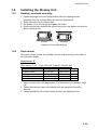
1.4
Installing the Display Unit
1.4.1
Desktop, overhead mounting
1. Fasten the hanger to the mounting location with four tapping screws
(supplied). See the outline drawing for mounting dimensions.
2. Screw the knobs into the display unit.
3. Set display unit to the hanger and tighten the knobs.
4. Run the ground wire between the ground terminal on the display unit and the
ship’s superstructure.
Desktop
Overhead
Display unit mounting methods
1.4.2
Flush mount
Two types of flush mounts are available. See the outline drawing at the back of
the manual for details.
Flush mount “F”
Flush mount “F” kit
Name
Cosmetic Panel
Tapping Screw
Hex Bolt
Spring Washer
Type: OP20-29, Code No: 000-041-405)
Type
20-016-1051
5X20
M6X12
M6
Code No.
100-251-370
000-802-840
000-862-127
000-864-260
Qty
1
4
2
2
1. Make a cutout in the mounting location. The dimensions are 183(W) x 92(H)
mm.
2. Fasten the cosmetic panel to the display unit with hex bolts and spring
washers.
3. Fasten the display unit to the mounting location with tapping screws.
1-15
1. INSTALLATION
Flush mount “S”
Flush mount “S” kit
Name
Flush Mount Fixture
Wing Bolt
Wing Nut
Hex Bolt
Spring Washer
Type: OP20-17, Code No.: 000-040-720)
Type
20-007-2401
M4X30
M4
M6X12
M6
Code No.
100-183-190
000-804-799
000-863-306
000-862-127
000-864-260
Qty
2
4
4
2
2
1. Make a cutout in the mounting location. The dimensions are 167(W) x 92(H)
mm.
2. Place the display unit in the cutout.
3. Fix the display unit to the two flush mount fixtures with hex bolts and spring
washers.
4. Screw the butterfly nut on the butterfly bolt.
5. Fix the display unit with the butterfly bolt and then tighten the butterfly nut.
Flush mount “S”
1-16
1. INSTALLATION
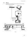
1.5
Wiring
This section covers general wiring. For further details see the interconnection
diagram at the back of this manual.
ANTENNA UNIT
SC-603
ANTENNA UNIT
SC-303
OR
2
3
PROCESSOR UNIT
SC-501
DPYC 1.5
TPPX6-3D2V-15M, 15m
or
TNC-PS-3D-15 (3 pcs.)
12-24 VDC
MJ-A7SPF0006-100,
10m
DISPLAY UNIT
SC-502
*
GPS ANT
1
2
3
DISPLAY
ANTENNA Terminals
GPS ANT1: No color
GPS ANT2: Yellow line
GPS ANT2: Red line
(using cable TPPX6-3D2V-15M)
Cable from display
Ground Terminal
Connect IV-2.0 sq
ground wire to
ship’s superstructure.
Wiring
1-17
1. INSTALLATION
Note 1: Use cable type DPYC-1.5 (or equivalent) for the power cable.
DPYC-1.5
Armor
Sheath
φ = 11.7 mm
Conductor
S = 1.5 mm 2
φ = 1.56 mm
Sectional view of coaxial cable DPYC-1.5
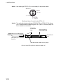
Note 2: The optional antenna cable set (CP20-01700 or CP20-01710) allows
you to extend antenna cable length to 30 m (50 m). See next page for
how to attach the connector.
Wrap each
junction with
tape.
Attach connector
N-P-8DFB in field.
To processor
unit
(OR Open-type
Antenna)
1m
30 or 50 m
1m
Bind the coaxial cables with vinyl tape.
How to install the optional antenna cable set
1-18
1. INSTALLATION
How to attach connector N-P-8DFB
Outer Sheath
Armor Inner Sheath Shield
(Dimensions in millimeters.)
30
50
Cover with heat-shrink tubing and heat.
Cut off insulator and core by 10 mm.
10
Twist shield end.
Slip on clamp nut,
gasket and clamp as shown left.
Clamp Nut Gasket Clamp
(reddish
brown) Aluminum Foil
Fold back shield over clamp and trim.
Trim shield here.
Insulator
Cut aluminum foil at four places,
90 from one another.
Fold back aluminum foil onto shield
and trim.
Trim aluminum
tape foil here.
1
Expose the insulator by 1 mm.
5
Clamp Nut
Pin
Shell
Solder through
the hole.
Expose the core by 5 mm.
Slip the pin onto the conductor.
Solder them together through the
hole on the pin.
Insert the pin into the shell.
Screw the clamp nut into the shell.
(Tighten by turning the clamp nut.
Do not tighten by turning the shell.)
How to attach connector N-P-8DFB
1-19
1. INSTALLATION
1.6
Initial Settings
Follow the procedures in this section to enter initial settings.
NOTICE
Improper menu settings may stop output of
data and display the message "RATE
ERROR." Be sure to enter correct data.
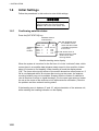
1.6.1
Confirming satellite status
Press the [SAT STATUS] key.
Satellites used for
measurement
SAT TRACKING STATUS
Satellites
being
tracked
TIMER 5 '52"
OK
NO. GOOD STATUS
GPS1 8
8
D3D
GPS2 7
7
D3D
GPS3 8
8
D3D
"OK" displayed when
the "GOOD" column
shows that the number
of satellites acquired is
five or more.
"3D" shown when no
beacon receiver is used.
"W3D" shown when
receving WAAS.
Satellite tracking status display
When the system is turned on for the first time it is in the “cold-start” state, which
means there is no satellite data (almanac data) stored. In this condition it takes
about 12 minutes to find heading. When heading is found the display shows
“OK.” The timer at the top left corner of the screen shows time since power on. If
OK is not displayed within 30 minutes after turning on the power, the antenna
mounting location may not be suitable. Suspect that the number of satellites in
view is less than five due to signal blockage. (For the open-type antenna, loosen
the nut at the center of the antenna unit to adjust antenna orientation.) Resolve
the problem and then recheck tracking status.
If the heading error is between 5° and 10°, adjust orientation of the antenna unit,
while watching the heading indication on the display.
1-20
1. INSTALLATION
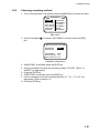
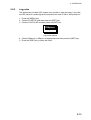
1.6.2
Choosing mounting method
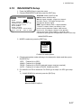
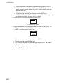
1. Turn on the processor unit and then press the [MENU] key to show the menu.
MAIN MENU
ALARMS
MESSAGES
GPS SETUP
SYS SETUP
SOFT VER.
OTHERS
SATELLITE
WAAS/DGPS
I/O SETUP
INST MENU
ERASE
TRIP MENU
Main menu
2. Use the Omnipad (
key.
) to choose “INST MENU” and then press the [ENT]
INSTALLATION SETUP
MOUNTING
DIRECTION
: WALL
:A
LANGUAGE
: ENG
ROLL OFFSET : 0.0
PITCH OFFSET : 0.0
Installation setup menu
3. “MOUNTING” is selected; press the [ENT] key.
4. Use the Omnipad to choose the mounting method: “FLOOR”, “WALL” or
“INVERT” as appropriate.
5. Press the [ENT] key.
6. “DIRECTION” is selected; press the [ENT] key.
7. Use the Omnipad to choose mounting direction (“A ”, “B ”, “C” or “D”) as
appropriate. Refer to section 1.3.
8. Press the [ENT] key.
1-21
1. INSTALLATION
1.7
Connection of External Equipment
1.7.1
General wiring
All external equipment are terminated on the MAIN Board inside the processor
unit. Turn off the power and unfasten four screws to remove the cover. Connect
wiring from external equipment referring to the interconnection diagram. Use the
terminal opener supplied to open terminal blocks, referring to the instructions
below.
Recommended Cables*:
Power cable:
DPYC-1.5
IEC 61162 equipment: TTYCS-1
AD-10 equipment:
TTYCS-1Q
* Or equivalent
How to insert cores in terminal blocks
Opener
1. Insert opener.
2. Press opener.
3. Insert core.
4. Release opener.
Power Cable
From top: Analog Roll, Analog Pitch, 2-pole. See Note.
LOG/ALARM (Contact signal, 6-pole)
DATA IN (AD-10/IEC 61162-1/2, 5-pole)
BEACON EXT (RTCM SC-104, 3-pole)
DATA OUT6 (AD-10, 4-pole)
DATA OUT1-DATA OUT5 (AD-10/IEC 61162-1/2, 4-pole)
Processor unit, cover opened
Note 1: Attach labels (supplied) to cables to differentiate between them.
Note 2: A plastic sheet is placed across the cable glands of the processor unit to keep out
foreign material. Cut out holes in the plastic where cables are to be lead in.
Note 3: Roll, pitch analog out voltage [V] = 0.0785 x θ (deg.) + 3.5 (θ = roll, pitch angle)
Output example
Roll or pitch angle
0 [deg]
5 [deg]
10 [deg]
20 [deg]
1-22
Analog out voltage
3.5 [V]
3.8925 [V]
4.285 [V]
5.07 [V]
1. INSTALLATION
1.7.2
Fabrication of cables
Cable
Power
cable
DPCY-1.5
(or
equivalent)
Sectional view, fabrication
50
Armor
Armor
Cut the sheath.
Conductor
S = 1.5 mm 2
φ = 1.56 mm
15
6
Vinyl tape
Crimp-on lug
FV1.25-5
FABRICATION
SECTIONAL VIEW
Cable for
AD-10
format
equipment
((JIS cable
TTYCS-1Q
or
equivalent)
Sheath
Sheath
φ = 11.7 mm
Cable for
IEC 61162
format
equipment
(JIS cable
TTYCS-1
or
equivalent)
50
Lay in clamp
where paint
was removed.
3
80
Armor
Braided shield
Armor
Sheath
Shield
φ = 10.1 mm
Conductor
S = 0.75 mm 2
φ = 1.11 mm
8
Twist and cut.
SECTIONAL VIEW (TTYCS-1)
6
Four cores on TTYCS-1Q
Solder
Armor
Sheath
Shield
φ = 11.3 mm
Conductor
S = 0.75 mm2
φ = 1.11 mm
SECTIONAL VIEW (TTYCS-1Q)
Ground wire (70)
15
10
Remove paint by
40 mm, clamp this
part in cable clamp.
Vinyl tape
Ground wire: Fasten to fixing screw on pcb.
FABRICATION
NOTE ON WIRING
1) Ground both this unit
and external equipment.
2) Fabricate braided shield of external equipment as follows:
- IEC 61162-1 input, AD-10 input (photo coupler): Connect to FG(frame ground).
- IEC 61162-2 input (RS-422/485): Connect to SG(signal ground).
Note: The power section of this equipment is insulated so the potential of SG and FG are the
same. If the shielding is not properly done, the data output IC may be damaged.
1-23
1. INSTALLATION
(This page intentionally left blank.)
1-24
2
OPERATION
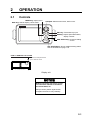
2.1
Controls
MENU key: Opens menu.
DISP key: Selects display; closes menu.
Omnipad: Selects menu items; shifts cursor.
MENU
ENT
ENT key: Terminates key input.
DISP
DIM
DIM key: Adjusts panel illumination,
display contrast.
HDG
SETUP
SATELLITE SAT
COMPASS STATUS
HDG SETUP key: Chooses heading
source. SAT STATUS key: Shows satellite tracking status.
See the illustration on page 1-20.
HOW TO REMOVE THE COVER
Press here and pull toward
you to remove cover.
Display unit
NOTICE
Reduced accuracy may occur in case
of unfavorable satellite constellation,
worsened HDOP, etc.
Always confirm position against other
navigation devices to verify reliability.
2-1
2. OPERATION
2.2
Turning the Power On/Off
Use the power switch on the processor unit to turn the power to the display unit
on and off.
POWER
Switch
Processor unit
A beep sounds and the display starts up with the last-used display.
Note: If backup heading data is used the heading indication flashes until faithful
heading data becomes available.
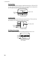
2.3
Panel Illumination, Display Contrast
1. Press the [DIM] key.
DIMMER (1-8)
4
CONTRAST (0-63)
45
EXIT: [ENT]
Dialog box for adjustment of panel illumination, display contrast
2. Press ▲ or ▼ to adjust panel illumination (dimmer).
3. Press ◄ or ► to adjust display contrast.
4. Press the [ENT] key.
2-2
2. OPERATION
2.4
Choosing a Display
Use the [DISP] key to show a display desired.
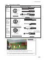
2.4.1
Description of displays
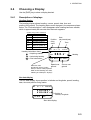
Heading display
The heading display shows heading, course, speed, date, time and
position-fixing status. The heading status mark changes in the sequence shown
below. The “final calculations” mark disappears after heading becomes reliable,
which is approximately 90 seconds after that mark appears.
Position-fixing status indications
2D
2D GPS position fix
3D
3D GPS position fix
D2D
2D DGPS position fix
D3D
3D DGPS position fix
SIM
Simulation mode
W2D
WAAS 2D position fix
W3D
WAAS 3D position fix
Positionfixing
status
3D
Heading Calculation Status
= Acquiring satellite
HDG
= Calculating heading
= Final calculations
SOG
Date
(day/month/year)
Time
04 - 1 - 15
23:54:13
28 3. 0°
0 .0
kt COG
Speed over
When the data
ground
of external sensor is input,
EXT (in reverse video) replaces
HDG on the Heading, Nav data,
Steering and Compass displays.
Heading
1 2 3 .4 °
Course over
ground
Nav data display
The nav data display shows position in latitude and longitude, speed, heading,
date, time and position-fixing status.
3D
04 - 1 - 15
00:00:00
0 °0 0. 0 0 0 ’ N
0 °0 0. 0 0 0 ’ E
SOG
0 .0
kt HDG
2 7 8 .0 °
Position in
Latitude, Longitude
Nav data display
2-3
2. OPERATION
Steering display
The steering display shows heading in digital and analog form. SOG and COG
are also indicated. Note that COG accuracy is low when the own ship speed is
low. The faster the speed, the more accurate the COG.
07:54
3D
27 8. 0°
HDG
Bearing
scale
250
260
270
0 .0
SOG
280
290
kt COG
Lubber’s mark
300
1 2 3 .4 °
Steering display
Compass display
The compass display shows heading by compass direction. Pitch and roll are
also indicated. The compass rose rotates with heading.
3D
23:24:01
HDG
Pitching
0. 0
°
PIT
+0
ROL
+0°
NW
W
N
°
Own ship symbol
SW
NE
S
Rolling
E
SE
Compass display
ROT (Rate-of-Turn) display
The ROT display provides digital and analog indications of rate of turn.
3D
30
ROT
scale
PORT
ROT
ROT
20 10
0
10
STBD
1 2 . 2 °/min
ROT display
2-4
20 30
2. OPERATION
Speed display
Depending on the setting of DISTANCE DISP on the TRIP menu, the Set and
Drift display or the Distance Run display is shown. The current indication
requires a Doppler Speed Log.
Ground speed
3D
SOG
kt
3D
SOG
kt
21.1 2.2
21.1 2.2
22.2
STW
kt
22.2
STW
kt
CURRENT
3 6 . 8° 2 . 5 kt
DISTANCE
Current (direction, speed)
4 5 6. 7 8
nm
Lateral
speed
Speed
relative to
water
Distance run
SOG/STW display
2-5
2. OPERATION
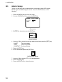
2.5
Alarm Setup
The SC-50 can alert you with audible and visual alarms when GPS signal,
DPGS signal and WAAS signal are lost. To set the DGPS alarm, do the
following:
1. Press the [MENU] key to show the menu.
2. Choose ALARMS and then press the [ENT] key.
ALARMS
BUZZER
DGPS
: LONG
: OFF
Alarm menu
3. BUZZER is selected; press the [ENT] key.
SHORT
LONG
CONSTANT
Buzzer options
4. Use ▲ or ▼ to choose buzzer type desired and then press the [ENT] key.
SHORT:
Two short beeps
LONG:
Three long beeps
CONSTANT: Continuous beep
5. Press the [ENT] key.
6. DPGS is selected; press the [ENT] key.
OFF
ON
DGPS alarm options
7. Use ▲ or ▼ to choose OFF or ON as appropriate.
8. Press the [ENT] key.
9. Press the [DISP] key to close the menu.
2-6
2. OPERATION
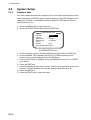
2.6
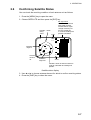
Confirming Satellite Status
You can check the receiving condition of each antenna unit as follows:
1. Press the [MENU] key to open the menu.
2. Choose SATELLITE and then press the [ENT] key.
RX signal level
Horizontal bar extends
with signal strength.
Satellite whose signal
strength extends past
the first vertical line
is used for heading and
position calculation.
PositionNorth
fixing
status
DOP
3D
DOP
1. 5
N
06
02
----
08
9
04
30
--
10
12
Antenna
element
no.
14
18
07
Elevation
angle 5°
23
01
GPS1
Elevation
angle 45°
-05
24
18
134
WAAS
Satellites shown in white on black are
used for calculation of heading and
position.
Satellite status display
3. Use ◄ or ► to choose antenna element for which to confirm receiving status.
4. Press the [DISP] key to close the menu.
2-7
2. OPERATION
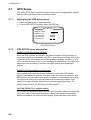
2.7
GPS Setup
The GPS SETUP menu smoothes position and course, averages speed, applies
position offset, and deactivates unhealthy satellites.
2.7.1
Displaying the GPS setup menu
1. Press the [MENU] key to open the menu.
2. Choose GPS SETUP and then press the [ENT] key.
GPS SETUP
SMOOTH POS
SMOOTH S/C
LAT OFFSET
LON OFFSET
DISABLE SV
:
:
:
:
:
0SEC
5SEC
0.000’N
0.000’E
GPS SETUP menu
2.7.2
GPS SETUP menu description
SMOOTH POS (Smoothing position)
When the DOP (Dilution of Precision, the index for position-fixing accuracy) or
receiving condition is unfavorable, the GPS fix may change randomly, even if the
vessel at anchor. This change can be smoothed by averaging a number of GPS
fixes. The setting range is from 0 (no smoothing) to 999 seconds. The higher the
setting the more smoothing. However, too high a setting slows updating of
position.
SMOOTH S/C (Smoothing speed/course)
Ship’s speed and course are directly measured by receiving GPS satellite
signals, independent of positions. The data varies with receiving conditions and
other factors. You can reduce this random variation by increasing the smoothing.
The higher the setting the more that speed and course are smoothed. If the
setting is too high, however, the follow-up to actual values gets slower. The
setting range is from 0 (no smoothing) to 999 seconds.
LAT/LON OFFSET (L/L position offset)
If GPS fixes are erroneous while at anchor, enter a position offset to compensate
for position error. Consult a nautical chart to determine latitude and longitude
differences between the chart and GPS display. Enter that value as the offset.
2-8
2. OPERATION
DISABLE SV (Disable satellite)
Every GPS satellite is broadcasting abnormal satellite number(s) in its Almanac,
which contains general orbital data about all GPS satellites. Using this
information, the GPS receiver automatically eliminates any malfunctioning
satellite from the GPS satellite schedule. However, the Almanac sometimes may
not contain this information. If you hear of an inoperative satellite you can
disable it manually. Enter satellite number in two digits and then press the [ENT]
key. To restore a satellite, enter “00”.
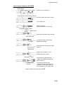
2.8
Output Data
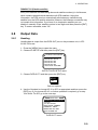
2.8.1
Heading
Heading data is output from the DATA OUT port on the processor unit, in IEC
61162-1/2 format.
1. Press the [MENU] key to open the menu.
2. Choose I/O SETUP and then press the [ENT] key.
OUTPUT DATA SETUP
DATA OUT1: AD-10
DATA OUT2: AD-10
DATA OUT3: IEC
DATA OUT4: IEC
DATA OUT5: IEC
LOG PULSE: 200 P/NM
OUTPUT DATA SETUP menu
3. Choose DATA OUT1 and then press the [ENT] key.
AD-10
IEC
Data out options
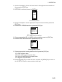
4. Use the Omnipad to choose AD-10 or IEC as appropriate and then press the
[ENT] key. If you choose AD-10, no further operation is required; go to step
18 to finish. For IEC go to the next step.
DATA OUT1
SENTENCE: HDG VTG ROT
HDT HDM
GLL ZDA VHW VBW
BAUD RATE: 4800BPS
INTERVAL: 100mS
NMEA VER: IEC ED2
HDG TALKER: GP
DATA OUT1 menu
2-9
2. OPERATION
5. Choose SENTENCE and then press the [ENT] key.
DATA OUT1
HDT
HDM
ROT
ATT
VDR
VTG
GGA
GNS
GLL
VHW
VBW
HVE
ZDA
DATA OUT1 menu, sentences
6. Use the Omnipad to choose a sentence and then press the [ENT] key.
HDT: True heading (required for radar, AIS, ECDIS, etc.)
HDM: Magnetic heading (HDM is obtained in this equipment by adding the
magnetic variation to HDT.)
ROT: Rate-of-turn data
ATT: True heading, pitching, rolling (FURUNO’s proprietary sentence)
VDR: Set and drift
VTG: Course over ground and ground speed
GGA: Global positioning system (GPS) fix data
GNS: GNSS fix data
GLL: Geographic position, latitude/longitude
VHW: Water speed and heading
VBW: Dual ground/water speed
HVE: GPS antenna up-down motion amplitude (FURUNO proprietary
sentence)
ZDA: Time and date
OFF
ON
7. Use the Omnipad to choose OFF or ON as appropriate and then press the
[ENT] key. Sentences selected for output are marked with an asterisk.
8. Repeat steps 6 and 7 for other items. All sentences cannot be selected. The
message “SENTENCE OVERLOAD” appears when too many sentences
have been selected. Change settings as appropriate. For further information
see page 2-12.
9. Press the [MENU] key to return to the DATA OUT1 menu.
10. Choose BAUD RATE and then press the [ENT] key.
4800BPS
9600BPS
19200BPS
38400BPS
Baud rate options
2-10
2. OPERATION
11. Use the Omnipad to choose the baud rate of the equipment connected and
then press the [ENT] key.
12. INTERVAL is selected; press the [ENT] key.
25ms
100ms
200ms
1S
2S
Tx interval options
13. Use the Omnipad to choose appropriate output interval and then press the
[ENT] key.
14. Choose IEC VERSION and then press the [ENT] key.
IEC ED1
IEC ED2
NMEA 1.5
IEC, NMEA version options
15. Choose appropriate IEC (or NMEA) edition and then press the [ENT] key.
16. Choose HDG TALKER and then press the [ENT] key.
GP
HE
HN
HC
Heading talker options
17. Choose appropriate heading talker and then press the [ENT] key.
GP: GPS navigator talker
HE: North-seeking gyrocompass talker
HN: Non-north seeking gyrocompass talker
HC: Magnetic compass talker
18. Press the [DISP] key to close the menu, or press the [MENU] key to return to
the I/O SETUP menu to setup another output port.
2-11
2. OPERATION
Output sentence limitation
The number of sentences which can be output depends on baud rate and output
interval settings. The maximum number of characters per each data sentences
are shown in the table below and the total number of characters must satisfy the
formula shown below. The number of characters which can be output “N” is
calculated by the following formula
N < 0.083 x T x B
T: Interval (s)
B: Baud rate
Sentence and maximum number of characters
Sentence
HDT
HDM
ROT
ATT
HVE
VTG*
GGA*
GNS*
GLL*
ZDA*
VHW*
VBW*
VDR*
No. of
Characters
19
19
21
34
23
46
66
62
47
36
44
45
35
*: Output is 1 s if interval set is shorter than 1 s.
For example, the baud rate is 4800 bps, interval is 100 ms (= 0.1 s). Therefore,
the number of characters is N <0.083 x 0.1(s) x 4800(bps) = 39.4.
Then, the number of characters which can be output is 39. For sentences
(sentences not having an asterisk in the table) where the output interval is
variable the number of characters is as shown in the table, however sentences
where the output interval is not smaller than 1 s (asterisk-marked sentences in
table) the number of characters which can be output is “number of characters in
table” x “setting interval.”
For the above settings the following applies:
• If both HDT and HDM are selected the total number of characters is 19+19 =
38. Since the count is less than 39 both can be selected.
• If both HDT and VTG are selected the total number of characters is
19+46x0.1=23.6. Since the count is less than 39 both can be selected.
• If HDT, HDM and VTG are selected the total number of characters is
19+19+46x0.1=42.6. In this case, the message “SENTENCE OVERLOAD”
appears.
2-12
2. OPERATION
2.8.2
Log pulse
This equipment provides SOG (speed over ground) in high accuracy. It converts
an SOG value to a pulse signal and outputs at the rate of 200 or 400 pulses/nm.
1. Press the [MENU] key.
2. Choose I/O SETUP and then press the [ENT] key.
3. Choose LOG PULSE and then press the [ENT] key.
200p/nm
400p/nm
Log pulse options
4. Choose 200p/nm or 400p/nm as appropriate and then press the [ENT] key.
5. Press the [DISP] key to close the menu.
2-13
2. OPERATION
2.9
System Setup
2.9.1
Geodetic data
Your unit is preprogrammed to recognize most of the major chart systems of the
world. Although the WGS-84 system (default setting) is the GPS standard, other
categories of charts in other datum still exist. Match the GPS datum with the
chart system you use.
1. Press the [MENU] key to open the menu.
2. Choose SYS SETUP and then press the [ENT] key.
SYSTEM SETUP
DATUM
: WGS84
UNITS
: kt
TIME DIFF
: +00:00
TIME DISP
: 24 HOUR
TEST?
DEMO
: OFF
EXCHANGE BATTERY?
SYSTEM SETUP menu
3. Confirm that the cursor is selecting DATUM and then press the [ENT] key.
4. Choose WGS84 (GPS standard), WGS72 or OTHER according to the
nautical chart you use and then press the [ENT] key.
5. If you chose WGS72 or WGS84, press the [DISP] key to finish. For OTHER,
go to step 6.
6. Press the [ENT] key.
7. Use the Omnipad to enter chart number, referring to the geodetic chart list on
page A-2. Choose location with ◄ or ►; change value with ▲ or ▼.
8. Press the [ENT] key.
9. Press the [DISP] key to close the menu.
2-14
2. OPERATION
2.9.2
Units of measurement
Distance/speed can be displayed in nautical miles/knots, kilometers/kilometers
per hour, or miles/miles per hour.
1.
2.
3.
4.
5.
6.
7.
2.9.3
Press the [MENU] key to open the menu.
Choose SYS SETUP and then press the [ENT] key.
Choose UNITS.
Press the [ENT] key.
Choose unit of measurement combination desired; kt, km/h, mi/h.
Press the [ENT] key.
Press the [DISP] key to close the menu.
Using local time
GPS uses UTC time. If you would rather use local time, enter the time difference
(range: -13:30 to +13:30) between local time and UTC.
1.
2.
3.
4.
5.
Press the [MENU] key to open the menu.
Choose SYS SETUP and then press the [ENT] key.
Choose TIME DIFF and then press the [ENT] key.
Press ▲ or ▼ to display + or – as appropriate.
Enter time difference with the Omnipad. Choose digit with ◄ or ►; change
value with ▲ or ▼.
6. Press the [ENT] key.
7. Press the [DISP] key to close the menu.
2.9.4
Time format
Time can be displayed in 12 hour or 24 hour format.
1.
2.
3.
4.
5.
Press the [MENU] key to open the menu.
Choose SYS SETUP and then press the [ENT] key.
Choose TIME DISP and then press the [ENT] key.
Choose 12HOUR or 24HOUR as appropriate and then press the [ENT] key.
Press the [DISP] key to close the menu.
2-15
2. OPERATION
2.9.5
Demonstration mode
The demonstration mode provides simulated operation of the equipment.
1.
2.
3.
4.
5.
Press the [MENU] key to open the menu.
Choose SYS SETUP and then press the [ENT] key.
Choose DEMO and then press the [ENT] key.
Choose ON or OFF as appropriate and then press the [ENT] key.
Press the [DISP] key to close the menu.
The indication SIM appears at the top of the screen when the demonstration
mode is active. When the demonstration mode is first made active,
SIMULATION MODE appears when the power is turned on and it is erased
when any key is pressed.
2-16
2. OPERATION
2.10
WAAS/DGPS Setup
1. Press the [MENU] key to open the menu.
2. Choose WAAS/DGPS and then press the [ENT] key.
WAAS/DGPS
MODE
: GPS
WAAS SEARCH: AUTO 134
CORRECTIONS DATA SET: 00
DPGS STATION: AUTO
RATE: 000BPS
FREQ: 310.0kHz
STATION: GOOD* DATA:GOOD*
SIG. S: 55.2 dB* SNR: 22.0 dB*
STATION: Shows GOOD or NG.
DATA: Shows GOOD or NG.
SIG. S: Signal Strength. A figure be tween 0
and 99 is shown. The higher the figure the
stronger the beacon signal.
SNR: Signal to Noise Ratio. A figure between
1 and 22 is shown. When your boat is in the
service area of a beacon station, SNR should
be 21 or 22. If the figure is below 21 the position
will be inaccurate. If this happens, check for radar
interference, poor ground and generator noise on own ship.
WAAS/DGPS menu
3. MODE is selected; press the [ENT] key.
GPS
WAAS
DGPS
AUTO
Position fix mode options
4. Choose appropriate mode referring to the description below and then press
the [ENT] key.
GPS: Position fix by GPS
WAAS: Position fix by WAAS
DPGS: Position fix by DGPS (external beacon receiver required)
AUTO: Position fix in order of DGPS, WAAS and GPS
5. For WAAS or AUTO do as below. For DGPS go to step 6; for GPS go to step
8.
1) WAAS SEARCH is selected; press the [ENT] key.
AUTO
MANUAL
WAAS SEARCH options
2-17
2. OPERATION
2) Use the Omnipad to choose WAAS satellite search method, AUTO or
MANUAL as appropriate. For MANUAL, press the [ENT] key, enter WAAS
satellite number, referring to page AP-14 (7. What is WAAS?) and then
press the [ENT] key.
3) CORRECTIONS DATA SET is selected; press the [ENT] key.
CORRECTIONS DATA SET determines how to use the WAAS signal. Use
the default setting “00”. Do step 6 and 7 for DGPS.
6. Choose DPGS STATION and press the [ENT] key.
AUTO
MANUAL
AUTO/MANUAL options
7. Choose MANUAL or AUTO as appropriate and press the [ENT] key. For
AUTO got to step 8. For MANUAL do the following:
1) RATE is selected; press the [ENT] key.
50BPS
100BPS
200BPS
Baud rate options
2) Choose appropriate baud rate and press the [ENT] key.
3) FREQ is selected; press the [ENT] key.
4) The cursor is selecting the hundredths digit so press ▲ or▼ to display
appropriate digit. Press ► to shift the cursor to the tenths place.
5) Set other digits appropriately.
8. Press the [DISP] key to close the menu.
2-18
2. OPERATION
2.11
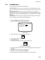
OTHERS Menu
The OTHERS menu contains the following items:
HOLD HDG DATA: Choose whether to display last-used heading data at power
on or not. Because this data is not reliable, the heading indication flashes to alert
you.
HDG RESTORATION: Choose how to restore GPS signal, automatically or
manually, after it is lost. For manual restoration, a key must be pressed to restart
heading output. This is done for safety purposes; for example, when an autopilot
is used.
HDG BACKUP: Choose how long to display backup data when the GPS signal
is lost. (This data is also output to external equipment.)
1. Press the [MENU] key to display the main menu.
2. Choose OTHERS and then press the [ENT] key.
OTHERS
HOLD HDG DATA: OFF
HDG RESTORATION : MAN
HDG BACKUP : 5MIN
Others menu
3. HOLD HDG DATA is selected; press the [ENT] key.
OFF
ON
4. Choose ON or OFF as appropriate.
5. Press the [ENT] key.
6. HDG RESTORATION is selected; press the [ENT] key.
MAN
AUTO
HDG RESTORATION options
7. Use the Omnipad to choose MAN or AUTO as appropriate and then press the
[ENT] key.
8. HDG BACKUP is selected; press the [ENT] key.
9. Choose 1, 2, 3, 4 or 5 minutes as appropriate.
10. Press the [ENT] key followed by the [DISP] key to close the menu.
2-19
2. OPERATION
2.12
TRIP Menu
The TRIP menu functions to
•
•
•
•
•
Choose the indication to show on the SOG/STW display
Choose source of distance run
Reset distance run to zero
Smooth the tide drift indication
Enter smoothing for rate of turn and display range scale
1. Press the [MENU] key to display the main menu.
2. Choose TRIP MENU and then press the [ENT] key.
TRIP MENU
DISTANCE DISP : DSTNC
DISTANCE CALC: GPS
RESET DISTANCE?
DRIFT AVG
: 10SEC
SMOOTH ROT: 2.5 SEC
ROT RANGE: 60°/MIN
TRIP menu
3. Choose DISTANCE DISP and then press the [ENT] key.
4. Choose what to display on the Speed display; distance run (DSTNC) or tide
direction and speed (DRIFT). Press the [ENT] key.
5. Choose DISTANCE CALC and then press the [ENT] key.
6. Choose the source for distance run; GPS, VLW (distance traveled through
water) or VBW (Dual ground/water speed). (VLW requires DS-80 type
Doppler speed log and VBW requires Current indicator or Doppler speed
log.) Press the [ENT] key.
7. Choose DRIFT AVG. and then press the [ENT] key.
8. If tide current and speed data is unstable, enter a smoothing figure to
stabilize the data. The higher the figure the more smoothed the data. A
setting between 0 (no smoothing) and 9999 (seconds) is available.
9. Choose SMOOTH ROT and then press the [ENT] key.
10. Use the Omnipad to enter rate of turn smoothing rate. Choose location with
◄ or ►; change value with ▲ or ▼. The setting range is 0.1 to 30.0
(seconds).
11. Press the [ENT] key.
12. Choose ROT RANGE and the press the [ENT] key.
13. Choose the range of the ROT graph from among 30, 60 and 90 (degree/min.)
and then press the [ENT] key.
14. Press the [DISP] key to close the menu.
2-20
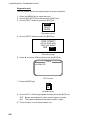
2. OPERATION
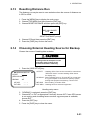
2.13
Resetting Distance Run
The distance run may be reset to zero as below when the source of distance run
is GPS or VBW.
1. Press the [MENU] key to display the main menu.
2. Choose TRIP MENU and then press the [ENT] key.
3. Choose RESET DISTANCE and then press the [ENT] key.
RESET DISTANCE?
ARE YOU SURE?
YES NO
RESET DISTANCE prompt
4. Choose YES and then press the [ENT] key.
5. Press the [DISP] key to close the menu.
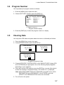
2.14
Choosing External Heading Source for Backup
Choose the source of heading data as below.
CAUTION
Never switch from internal to external
heading while the autopilot is in the
automatic mode. Change to the
manual mode before switching.
1. Press the [HDG SETUP] key.
HEADING SETUP
OFFSET
: +000.0°
(SERVICE ONLY)
: INT
HEADING
INT HDG
EXT HDG
- - - . -°
- - - . -°
OFFSET : Heading offset. See service manual for instructions.
"SERVICE ONLY" means heading offset shown
for display only.
HEADING : Select heading source. Choose INT for normal use.
If a gyrocomapss is connected for primary means,
leaving this equipment as backup, choose EXT.
INT HDG : Bow heading. Includes offset.
EXT HDG : Heading fed from external equipment.
Heading setup menu
2. ”HEADING” is selected; press the [ENT] key.
3. Choose INT or EXT as appropriate. Normally choose INT. If own GPS sensor
is not working and a heading sensor such as a gyrocompass is available,
choose EXT.
4. Press the [ENT] key.
5. Press the [DISP] key to close the menu.
2-21
3
MAINTENANCE,
TROUBLESHOOTING
WARNING
ELECTRICAL SHOCK HAZARD
Do not open the equipment.
Only qualified personnel
should work inside the
equipment.
3.1
Preventive Maintenance
Regular maintenance is important for good performance. A maintenance
program should be established and should include the following points.
• Check connectors and ground terminal on the processor unit and display unit
for tightness.
• Check ground terminal for rust. Clean or replace as necessary.
• Check for water leakage in the antenna cable. Replace the cable if there are
signs of water leakage.
• Remove dust and dirt from the display unit and processor unit with a dry, soft
cloth. For the LCD, wipe it carefully to prevent scratching, using tissue paper
and an LCD cleaner. To remove stubborn dirt, use an LCD cleaner, wiping
slowly with tissue paper so as to dissolve the dirt. Change paper frequently so
the dirt will not scratch the LCD. Do not use chemical cleaners for cleaning they can remove paint and markings.
3-1
3. MAINTENANCE, TROUBLESHOOTING
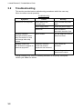
3.2
Troubleshooting
This section provides basic troubleshooting procedures which the user may
follow to restore normal operation.
Troubleshooting
Symptom
Cannot turn on the power.
Cause
Remedy
Power cable on the
processor unit
Firmly connect the power
cable
Power supply failure
Check the power supply.
Blown fuse
Have a qualified
technician check the fuse.
Heading indication
changes randomly when
ship is at anchor or does
not change when ship
moves.
Sensor trouble
Run the diagnostic test2 to
determine cause.
Heading output from
SC-50 does not appear on
external equipment.
Connection between
SC-50 and external
equipment has loosened.
Firmly fasten the
connector.
Sensor trouble
Run the diagnostic test1 to
determine the cause.
If large heading error occurs or heading indication is frequently interrupted,
contact your dealer for advice.
3-2
3. MAINTENANCE, TROUBLESHOOTING
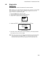
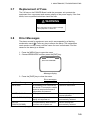
3.3
Diagnostics
Diagnostic test1
The diagnostic test1 checks the equipment for proper operation.
Note: Heading is not output during the diagnostic test, and this is communicated
with an appropriate message. After completing the diagnostic test, turn the
power off and on to update heading data.
1. Press the [MENU] key to open the menu.
2. Choose SYS SETUP and then press the [ENT] key.
3. Choose TEST? and then press the [ENT] key.
TEST1
TEST2
TEST3
Test menu options
4. Confirm that TEST1 is selected and then press the [ENT] key.
TEST START?
(STOP: PWR OFF)
ARE YOU SURE?
YES
NO
Test start prompt
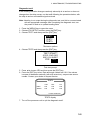
5. Press ◄ to choose YES and then press the [ENT] key. The test proceeds in
the sequence shown on the next page.
Note: The output port test (see next page) is intended for the service technician,
using a special test connector. If TEST1 is conducted without the test
connector, disconnect the DATA IN connector from the processor unit.
3-3
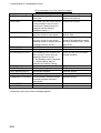
3. MAINTENANCE, TROUBLESHOOTING
ROM, RAM, KEY TEST
OK shown for normal;
NG (No Good) shown for error
GPS receiver
Processor unit
Display unit
ROM
OK
OK
OK
OK
OK
GPS1
GPS2
GPS3
CAL
DISP
CNT=
RAM
OK
OK
OK
OK
OK
PUSH KEY
OK
KEY TEST
Press each key one by
one. Pressed key’s name
appears here if key
is functioning properly.
(STOP: PWR OFF)
Number of
times test
executed
After 3 sec.
OUTPUT TEST
(for serviceman)
OUT1
OUT2
OUT3
OUT4
OUT5
OUT6
AD-10
IEC
-------
------
To stop the test turn
off the power.
After 5 sec.
(For serviceman)
B-EXT
DISP
-OK
All LCD segments go on 2 sec.,
All LCD segments go off 3 sec.
DISPLAY TEST
<LCD CHECK>
ALL ON 2 SEC.
ALL OFF 3 SEC.
PROGRAM NUMBER
DISPLAY
SOFTWARE VERSION
DISPLAY
PROCESS
GPS1
GPS2
GPS3
CNT=
205-1342-**.**
205-1341-**.**
4850263***
4850263***
4850263***
** Program
Version No.
(STOP: PWR OFF)
ROM, RAM, KEY check appears after
3 sec.
Diagnostic test sequence
6. Turn off the processor unit to quit the diagnostic test1.
3-4
3. MAINTENANCE, TROUBLESHOOTING
Diagnostic test2
If the heading indication changes randomly when ship is at anchor or does not
change when the ship moves, run the test2 following the procedure below, with
the ship at anchor and satellite signal received.
Note: Heading is not output during the diagnostic test, and this is communicated
with an appropriate message. After completing the diagnostic test, turn
the power off and on to update heading data.
1. Press the [MENU] key to open the menu.
2. Choose SYS SETUP and then press the [ENT] key.
3. Choose TEST? and then press the [ENT] key.
TEST1
TEST2
TEST3
Test menu options
4. Choose TEST2 and then press the [ENT] key.
TEST START?
(STOP: PWR OFF)
ARE YOU SURE?
YES
NO
Test start prompt
5. Press ◄ to choose YES and then press the [ENT] key.
6. Press the [ENT] key twice. Rate and angle values are 0.0°. If the values
increase or decrease markedly (with ship at anchor), suspect rate sensor
trouble. Contact your dealer to request service.
TEST2
RATE
ANGLE
YAW
ROL
PIT
0.0°
0.0°
0.0°
0.0°
0.0°
0.0°
<STOP: PWR OFF>
TEST2 display
7. Turn off the processor unit to quit the diagnostic test2.
3-5
3. MAINTENANCE, TROUBLESHOOTING
Diagnostic test3
This test checks the buzzer signal/contact for proper operation.
1. Press the [MENU] key to open the menu.
2. Choose SYS SETUP and then press the [ENT] key.
3. Choose TEST? and then press the [ENT] key.
TEST1
TEST2
TEST3
Test menu options
4. Choose TEST3 and then press the [ENT] key.
TEST START?
(STOP: PWR OFF)
ARE YOU SURE?
YES
NO
Test start prompt
6. Press ◄ to choose YES and then press the [ENT] key.
TEST3
ALARM: OFF
TEST3 menu
7. Press the [ENT] key.
OFF
ON
ALARM options
8. Choose OFF or ON as appropriate and then press the [ENT] key.
OFF: Buzzer sound goes off, alarm contact signal is closed.
ON: The buzzer sounds and the alarm contact is open.
9. To quit the test, turn off the processor unit.
3-6
3. MAINTENANCE, TROUBLESHOOTING
3.4 Program Number
You may display the program number as follows:
1. Press the [MENU] key to open the menu.
2. Choose SOFT VER. and then press the [ENT] key.
SOFTWARE VERSION
DISPLAY
PROCESS
GPS1
GPS2
GPS3
205-1342-**.**
205-1341-**.**
4850263***
4850263***
4850263***
** = Program version no.
Program number display
3. Press the [DISP] key to close the program version no. display.
3.5
Clearing Data
You may clear GPS data and system data all at once or individually as follows:
1. Press the [MENU] key to open the menu.
2. Choose ERASE and then press the [ENT] key.
ERASE GPS DATA?
ARE YOU SURE?
YES
NO
ERASE ALL BACKUP
DATA? (DEFAULT)
ARE YOU SURE?
YES
NO
ERASE SYSTEM
DATA? (DEFAULT)
ARE YOU SURE?
YES
NO
Prompts for erasure of data
3. Choose GPS DATA?, SYSTEM DATA? or ALL BACKUP DATA? (clears GPS
and SYSTEM data) as appropriate. One of the following displays appears
depending on your selection.
4. Press ◄ to choose YES and then press the [ENT] key to erase. After data is
erased the message “Completed erasing. Turn off the unit.” is displayed.
Note: MOUNTING, DIRECTION and LANGUAGE in the INST menu, HDG
RESTORATION and HDG BACKUP in the OTHERS menu and
OFFSET in the HEADING SETUP menu are not cleared.
5. Turn off and on the power.
3-7
3. MAINTENANCE, TROUBLESHOOTING
3.6
Replacement of Battery
The processor unit has a battery which stores data when the power is turned off.
When the battery voltage is low, the message “BATTERY!” appears on the
display. Have a qualified technician replace the battery, following the procedure
below. The life of the battery is 3-5 years.
Battery Location
Processor Unit
Type
CR2450-F2ST2L
Code No.
000-144-941
1. Press the [MENU] key to open the menu.
2. Choose SYS SETUP and then press the [ENT] key.
3. Choose “EXCHANGE BATTERY?” and then press the [ENT] key.
EXCHANGE BATT?
ARE YOU SURE?
YES
NO
Prompt for exchanging battery
4. Press ◄ to choose YES and then press the [ENT] key. The following
message appears.
READY FOR
BATTERY CHANGE.
TURN OFF THE
UNIT.
Prompt for turning off the power
5. At this time the contents of the RAM are temporarily moved to the flash
memory. Turn off the power.
6. Have a qualified technician replace the battery.
Note: If the equipped will not be used for a long period of time, save data by
following the above procedure. This will prevent loss of data even if the
battery dies.
3-8
3. MAINTENANCE, TROUBLESHOOTING
3.7
Replacement of Fuse
The 3 A fuse on the POWER Board inside the processor unit protects the
equipment from overcurrent and reverse polarity of the power supply. If the fuse
blows, have a qualified technician check the fuse.
WARNING
Use the proper fuse.
Use of a wrong fuse can result in damage
to the equipment or cause fire.
3.8
Error Messages
The alarm sounds for equipment error and is accompanied by a flashing
exclamation mark ( ). Press any key to silence the alarm. The exclamation
mark remains on the screen until the cause for error is eliminated. Find the
cause for the alarm(s) as follows:
1. Press the [MENU] key to open the menu.
2. Choose MESSAGES and then press the [ENT] key.
MESSAGES
GPS DATA ERROR!
Message display
3. Press the [DISP] key to close the menu.
Error messages
Error Message
ABORTING!
ABORTING CALC!
Meaning
GPS heading error continues for
one minute. For example, satellite
cannot be acquired because of
unfavorable environment.
GPS signal lost for one minute.
Remedy
Check for obstruction.
Press any key to try to restore
normal operation.
BACKUP ERROR!(DISP)
Corrupted backup data found in
display unit at power on.
Default settings are
automatically restored.
BACKUP
ERROR!(PRCSSR)
Corrupted backup data found at
processor unit at power on.
Default settings are
automatically restored.
(Continued on next page)
3-9
3. MAINTENANCE, TROUBLESHOOTING
Error messages (con’t from previous page)
Error Message
BATTERY ALM!
Meaning
Remedy
Have battery replaced at
earliest convenience.
GPS NO FIX!
Voltage of battery in processor
unit is low.
GPS data (from the GPS receiver
in the processor unit) is lost for
one minute. Heading output is
stopped and the heading
indication shows “- - -“.
DGPS data (from external DGPS
receiver) is lost for one minute.
GPS data (from internal GPS
receiver) is lost for one minute.
Heading output is stopped and the
heading indication shows “- - -“.
No GPS data.
HDG ERROR!
Heading error
Request service.
NO HEADING OUTPUT!
Press any key to try to restore
normal operation.
RAM ERROR!
GPS heading error continues for
five* minutes. In this case the
heading indication shows “- -“ and heading output is stopped.
* = default setting. May be
changed by “backup” setting.
RAM problem
Request service.
RATE ERROR(YAW)!
Data output stopped.
Request service.
RATE ERROR(ROLL)!
Data output stopped.
Request service.
RATE ERROR(PITCH)!
Data output stopped.
Request service.
COMMUNICATION ERR!
Communication between display
unit and processor has been
interrupted.
Request service.
WAAS ERROR
WAAS data lost for one minute.
Request service.
ROM ERROR!
ROM problem
Request service.
DATA ERR!
DGPS ERROR!
GPS DATA ERROR!
*: Alarm port goes open when message appears.
3-10
Check GPS receiver.
Ship may not be within DPGS
service area.
Conduct diagnostic test1 and
check if NG appears for results
for GPS receivers GPS1, GPS2
and GPS3.
Check antenna cable.
APPENDIX
1. Menu Tree
MENU
ALARMS
BUZZER (SHORT, LONG, CONSTANT)
DGPS (OFF, ON)
MESSAGES
GPS SETUP
SMOOTH POS (0 SEC)
SMOOTH S/C (5 SEC)
LAT OFFSET (0.000’N)
LON OFFSET (0.000’E)
DISABLE SV
SYS SETUP
DATUM (WGS84, WGS72, OTHER 001 (WGS84))
UNITS (kt, km/h, mi/h)
TIME DIFF (+00:00)
TIME DISP (12 HOUR, 24 HOUR)
TEST? (TEST1, TEST2, TEST3)
DEMO (OFF, ON)
EXCHANGE BATTERY?
SOFT VER.
OTHERS
Default settings in bold italics
HOLD HDG DATA (OFF, ON)
HDG RESTORATION (MAN, AUTO)
HDG BACKUP (1-5 (MIN))
SATELLITE
WAAS/
DGPS
MODE (GPS, WAAS, DGPS, AUTO)
WAAS SEARCH (AUTO, MANUAL)
CORRECTIONS DATA SET (00-99, 00)
DGPS STATION (AUTO, MANUAL)
RATE* (50BPS, 100BPS, 200BPS) *000BPS in default setting.
FREQ (310.0kHz)
I/O SETUP
DATA OUT1
AD-10, IEC
DATA OUT2
DATA OUT3
DATA OUT4
DATA OUT5
LOG PULSE (200, 400 (p/nm))
SENTENCE (HDT, HDM, ROT
ATT, VDR, VTG, GGA, GNS,
GLL, VHW, VBW, HVE, ZDA)
BAUD RATE (4800, 9600,
19200, 38400)
INTERVAL (25ms, 100ms,
200ms, 1S, 2S)
NMEA VER (IEC ED1, IEC ED2, NMEA1.5)
TALKER (GP, HE, HN, HC)
INST MENU
MOUNTING (FLOOR, WALL, INVERT)
DIRECTION (A, B, C, D)
LANGUAGE (ENG, JPN)
ROLL OFFSET (-90.0 to +90.0, 0)
PITCH OFFSET (-90.0 to +90.0, 0)
ERASE
GPS DATA?
SYSTEM DATA?
ALL BACKUP DATA?
TRIP
MENU
DISTANCE DISP (DSTNC, DRIFT)
DISTANCE CALC (GPS, VLW, VBW )
RESET DISTANCE?
DRIFT AVG. (0-9999SEC, 10)
SMOOTH ROT (0.1 - 30.0, 2.5 (sec))
ROT RANGE (30, 60, 90 (°/min))
AP-1
APPENDIX
2. Digital Interface
Output sentences of channel 1
DATA OUT1-5: HDT, HDM, ROT, Patt, Phve, VTG, GGA, GLL, GNS, ZDA, VHW, VBW, VDR
DATA OUT 6: AD-10
Transmission interval
HDT, HDM, ROT, Patt, Phve: 100 ms
VTG, GGA, GLL, GNS, ZDA, VHW, VBW, VDR: 1 s
For details see page 2-12.
Load requirement as listener
Isolation: Optocoupler
Input Impedance: 220 ohms
Max. Voltage: ±15V
Threshold: 4 mA
Data transmission
Data is transmitted in serial asynchronous form in accordance with the standard referenced
in 2.1 of IEC 61162-1. The first bit is a start bit and is followed by data bits,
least-significant-bit as illustrated below.
The following parameters are used:
Baud rate: 4800
Data bits: 8 (D7 = 0), parity none
Stop bits: 1
D0
Start
bit
AP-2
D1
D2
D3
D4
Data bits
D5
D6
D7
Stop
bit
APPENDIX
Schematic diagrams
Data IN
20P8178
J9
FL35
R13
R108
1
1
220
2
FL36
3
4
U7
220
CR1
3
PC-40
5
1SS27
4
5
Load requirements
Isolation:
Optocoupler
Input Impedance: 440 ohm
Max. voltage:
±15V
Data Out 1-6
20P8178
J2
U1 max3043
1
2
3
4
FL5
11
FL6
10
FL7
FL8
13
14
9
15
Output drive capability
Max : 10mA
AP-3
APPENDIX
Data sentences
PFECatt- True heading, pitching, rolling
$PFEC,GPatt,xxx.x,+xx.x,-xx.x<CR><LF>
(Ver. 1.5)
$PFEC,GPatt,xxx.x,+xx.x,-xx.x*hh<CR><LF>
(Ver. 2.0)
Checksum (Ver. 2.0)
Rolling (output to tenths place)
Pitching (output to tenths place)
Heading, true (output to tenths place)
GGA - Global positioning system (GPS) fix data
Time, position and fix related data for a GPS receiver.
Differential reference station ID, 0000-1023
Age of differential GPS data
Units of geoidal separation, m
Geoidal separation
Units of antenna altitude, m
Antenna altitude above/below
mean sea level (geoid)
Horizontal dilution of precision
$GPGGA, hhmmss.ss. 1111.11, a, yyyyy.yy, a, x, xx, x.x, x.x, M, x.x, M, x.x, xxxx*hh<CR><LF>
Number of satellites in use, 11-12, may be
different from the number in view
GPS quality
Longitude - E/W
Latitude - N/S
UTC of position
GLL - Geographic position - latitude/longitude
Latitude and longitude of present vessel position, time of position fix and status.
$--GPGLL, 1111.11, a, yyyyy.yy, a, hhmmss.ss, A, p*hh<CR><LF>
Positioning system indicator*
Status: A = data valid
UTC of position
Longitude, E/W
Latitude, N/S
*A = Autonomous, D = Differential, E = estimated(dead reckoning), M = Manual input, S = Simulator,
N = Data not valid. The Mode indicator field supplements the Status field. The Status field shall be
set to V=invalid for all values of Operating Mode except for A=Autonomous and D=Differential. The
positioning system Mode indicator and Status field shall not be null fields.
AP-4
APPENDIX
GNS - GNNS fix data
$--GNS,hhmmss.ss,llll.lll,a,yyyyy.yyy,a,c--c,xx,x.x,x.x,x.x,x.x,x.x*hh<CR><LF>
|
| |
|
| |
| | | | | | |
|
| |
|
| |
| | | | | | +--- 11
|
| |
|
| |
| | | | | +------ 10
|
| |
|
| |
| | | | +---------- 9
|
| |
|
| |
| | | +-------------- 8
|
| |
|
| |
| | +------------------ 7
|
| |
|
| |
| +---------------------- 6
|
| |
|
| |
+------------------------- 5
|
| |
|
| +------------------------------ 4
|
| |
+-------+--------------------------------- 3
|
+---+--------------------------------------------- 2
+------------------------------------------------------------- 1
1. UTC of position
2. Latitude, N/S
3. Longitude, E/W
4. Mode indicator
5. Total number of satllite in use,00-99
6. HDOP
7. Antenna altitude, metres, re:mean-sea-level(geoid)
8. Geoidal separation
9. Age of differential data
10. Differential reference station ID
11. Checksum
HDM- Heading – magnetic
This sentence is not used in the current version of NMEA and IEC 61162. Some boaters may want the
GPS compass to indicate the magnetic heading when the boat is only fitted with a magnetic compass.
HDG is calculated by adding a geomagnetic variation to HDT.
$--HDM, x.x, M *hh<CR><LF>
Heading, degrees true
HDT - Heading - true
True heading in degrees obtained by processing RF cycle in the GPS carrier frequency.
$--HDT, x.x, T*hh<CR><LF>
Heading, degrees true
ROT – Rate of turn
ROT derived from a changing rate of GPS compass heading.
$--ROT, x.x, A*hh<CR><LF>
Status: A = data valid
Rate of turn, degrees/min, “-” = bow turns to port
AP-5
APPENDIX
VBW - Dual ground/water speed
$--VBW,x.x,x.x,A,x.x,x.x,A,x.x,A,x.x,A*hh<CR><LF>
| | | | | | | | | | |
| | | | | | | | | | +--- 11
| | | | | | | | | +----- 10
| | | | | | | | +-------- 9
| | | | | | | +----------- 8
| | | | | | +-------------- 7
| | | | | +----------------- 6
| | | | +-------------------- 5
| | | +------------------------ 4
| | +--------------------------- 3
| +------------------------------ 2
+---------------------------------- 1
1. Longitudial water speed, knots
2. Transverse water speed, knots
3. Status: water speed, A=data valid V=data invalid
4. Longitudial ground speed, knots
5. Transverse ground speed, knots
6. Status: ground speed, A=data valid V=data invalid
7. Stern transverse water speed, knots
8. Status: stern water speed, A=data valid V=data invalid
9. Stern transverse ground speed, knots
10. Status: stern ground speed, A=data valid V=data invalid
11. Checksum
VDR - Set and drift
$--VDR,x.x,T,x.x,M,x.x,N*hh<CR><LF>
| | | | | | |
| | | | | | +--------- 4
| | | | +--+----------- 3
| | +--+----------------- 2
+--+----------------------- 1
1. Direction, degrees true
2. Direction, degrees magnetic
3. Current speed, knots
4. Checksum
VHW - Water speed and heading
The compass heading to which the vessel points and the speed of the vessel relative to the water.
$--VHW,x.x,T,x.x,M,x.x,N,x.x,K*hh<CR><LF>
| | | | | | | | |
| | | | | | | | +--------- 5
| | | | | | +--+----------- 4
| | | | +--+----------------- 3
| | +---+----------------------- 2
+---+----------------------------- 1
1. Heading, degrees true
2. Heading, degrees magnetic
3. Speed, knots
4. Speed, km/h
5. Checksum
AP-6
APPENDIX
VLW - Distance travelled through the water
The distance travelled, relative to the water.
$--VLW,x.x,N,x.x,N*hh<CR><LF>
| | | | |
| | | | +--------- 3
| | +---+----------- 2
+---+----------------- 1
1. Total cumulative distance, nautical miles
2. Distance since reset, nautical miles
3. Checksum
VTG - Course over ground and ground speed
COG and SOG obtained by processing the GPS signals.
$GPVTG, x.x, T, x.x, M, x.x, N, x.x, K, p*hh<CR><LF>
Positioning mode indicator*
Speed, km/h
Speed, knots
Course degrees magnetic
Course degrees true
*A = Autonomous, D = Differential, E = estimated(dead reckoning), M = Manual input, S = Simulator,
N = Data not valid. The Mode indicator field supplements the Status field. The Status field shall be
set to V=invalid for all values of Operating Mode except for A=Autonomous and D=Differential. The
positioning system Mode indicator and Status field shall not be null fields.
ZDA - Time and date
UTC, day, month, year and local time zone.
$GPZDA. hhmmss.ss, xx, xx, xxxx, xx, xx*hh<CR><LF>
Local zone minutes description, same sign as local hours
Local zone description 00 h to ± 13 h (see note)
Year
Month, 01 to 12
Day, 01 to 31
UTC
NOTE - Zone description if the number of whole hours added to local time to obtain GMT. Zone
description is negative for east longitudes.
AP-7
APPENDIX
3. Input/Output Ports
Port
Label
DATA
OUT1
DATA
OUT2
DATA
OUT3
DATA
OUT4
DATA
OUT5
Terminal Name
I/O
Signal
Remarks
WAGO
231-304/026-000
WAGO
231-304/026-000
WAGO
231-304/026-000
WAGO
231-304/026-000
WAGO
231-304/026-000
O
Heading,
Speed,
Course,
Position,
and
Time
IEC61162(NMEA0183) or AD-10 format
(software)
IEC61162-1 (NMEA0183) Ver1.5, 2.0
IEC61162-2
Talker: GP, HE, HN,HC ( HDT, HDM, ROT
selectable; other sent. GP only)
Speed: 4800, 9600, 19200, 38400 bps
IEC61162 sentences: HDT, HDM, ROT, VTG,
GGA, GLL, GNS, ZDA, VHW, VBW, VDR
( on/off by menu )
IEC61162 (NMEA0183) : sentence output
interval : HDT, HDM, ROT : (25ms, 100ms,
200ms, 1s, 2s, selectable), VTG, GGA, GLL,
GNS, ZDA, VHW, VBW, VDR : (1s, 2s,
selectable)
ATT sentence
Proprietary sentence or FURUNO sentence
Only P sentence : output rate of 25ms,
100ms,200ms, 1s, 2s, selectable
O
O
O
O
ATT sentence – True heading, pitching, rolling
$PFEC,GPatt,xxx.x, +xx.x, +xx.x<CR><LF>
( IEC61162-1 (NMEA0183) Ver1.5 )
$PFEC,GPatt,xxx.x, +xx.x,
+xx.x*hh<CR><LF>
(IEC61162-1 (NMEA0183) ver 2.0,
IEC61162-2)
HVE sentence
Proprietary sentence or FURUNO sentence
Only P sentence : output rate of 25ms,
100ms,200ms, 1s, 2s, selectable
HVE sentence – heave by wave
$PFEC,GPhve,xx.xxx,A<CR><LF>
( IEC61162-1 (NMEA0183) Ver1.5 )
$PFEC,GPhve,xx.xxx,A *hh<CR><LF>
(IEC61162-1 (NMEA0183) ver 2.0,
IEC61162-2)
AD-10 output interval :25ms
Sinal level : IEC61162
Heading data selected in the tech menu is
output.
AP-8
APPENDIX
Port
Label
DATA
OUT6
LOG/
ALARM
DATA IN
Terminal Name
I/O
Signal
Remarks
WAGO
231-304/026-000
WAGO
231-306/026-000
O
Heading
O
LOG
Signal
HDG
alarm
Heading
AD-10 only
AD-10 output interval: 25ms
200 pulse/nm or 400 pulse/nm (software),
0.5A max.
WAGO
231-305/026-000
O
Heading alarm, 0.5A max, normal close
Heading data in either AD-10 or
IEC61162(NMEA0183) format (4800, 9600,
19200, 38400bps) is automatically received.
Priority of IEC61162(NMEA0183) sentence is
HDT>HDG>HDM.
The signal is selected through the menu
during the period of internal heading sensor
failure.
VBW/VHW may be input from a current
indicator.
AP-9
APPENDIX
4. Parts List and Parts Location
This equipment contains complex modules in which fault diagnosis and repair down to
component level are not practical (IMO A.694(17)/8.3.1. Only some discrete components
are used. FURUNO Electric Co., Ltd. believes identifying these components is of no value
for shipboard maintenance; therefore, they are not listed in the manual. Major modules can
be located on the parts location photo on this and then next page.
FURUNO
ELECTRICAL PARTS LIST
SYMBOL TYPE
Model
Unit
SC-50
SC-501
PROCESSOR UNIT
Ref.Dwg.
Blk.No.
Page
CODE No.
REMARKS
SHIPPABLE
ASSEMBLY
PRINTED CIRCUIT BOARD
20P8178, MAIN
20P8181, PWR
MAIN Board
(20P8178)
PWR Board
(20P8181)
Processor Unit, cover removed
AP-10
APPENDIX
FURUNO
Model
Unit
ELECTRICAL PARTS LIST
SC-50/110
SC-502
DISPLAY UNIT
Ref.Dwg.
Blk.No.
SYMBOL TYPE
Page
CODE No.
REMARKS
SHIPPABLE
ASSEMBLY
PRINTED CIRCUIT BOARD
20P8189, CPU
CPU Board
(20P8189)
Display Unit, cover opened
AP-11
APPENDIX
5. Geodetic Chart Codes
001:WGS84
002:WGS72
003:TOKYO
004:NORTH AMERICAN 1927
005:EUROPEAN 1950
006:AUSTRALIAN GEODETIC 1984
007:ADINDAN
008:
009:
010:
011:
012:AFG
013:AIN EL ABD 1970
014:ANNA 1 ASTRO 1965
015:ARC 1950
016:
017:
018:
019:
020:
021:
022:
023:ARC 1960
024:
025:
026:ASCENSION ISLAND 1958
027:ASTRO BEACON "E"
028:ASTRO B4 SOR. ATOLL
029:ASTRO POS 71/4
030:ASTRONOMIC STATION 1952
031:AUSTRALIAN GEODETIC 1966
032:BELLEVUE (IGN)
033:BERMUDA 1957
034:BOGOTA OBSERVATORY
035:CAMPO INCHAUSPE
036:CANTON ISLAND 1966
037:CAPE
038:CAPE CANAVERAL
039:CARTHAGE
040:CHATHAM 1971
041:CHUA ASTRO
042:CORREGO ALEGRE
043:DJAKARTA (BATAVIA)
044:DOS 1968
045:EASTER ISLAND 1967
046:EUROPEAN 1950 (Cont'd)
047:
048:
049:
050:
051:
052:
053:
054:
055:
056:
057:EUROPEAN 1979
058:GANDAJIKA BASE
059:GEODETIC DATUM 1949
060:GUAM 1963
061:GUX 1 ASTRO
062:HJORSEY 1955
063:HONG KONG 1963
064:INDIAN
065:
066:IRELAND 1956
067:ISTS 073 ASTRO 1969
068:JHONSTON ISLAND 1961
069:KANDAWALA
070:KERGUELEN ISLAND
071:KERTAU 1948
072:LA REUNION
073:L.C. 5 ASTRO
074:LIBERIA 1964
075:LUZON
076:
077:MAHE 1971
078:MARCO ASTRO
079:MASSAWA
080:MERCHICH
081:MIDWAY ASTRO 1961
082:MINNA
083:NAHRWAN
084:
085:
086:NAMIBIA
AP-12
:Mean Vallue (Japan, Korea, and Okinawa)
:Mean Vallue (CONUS)
:Mean Vallue
:Australla and Tasmania Island
:Mean Value(Ethiopia and Sudan)
:Ethiopia
:Mall
:Senegal
:Sudan
:Somalla
:Bahrain Island
:Cocos Island
:Mean Value
:Bostswana
:Lesotho
:Malawi
:Swazlland
:Zaire
:Zambla
:Zimbabwe
:Mean Value (Kanya, Tanzania)
:Kenya
:Tanzania
:Ascension Island
:Iwo Jima Island
:Tem Island
:St. Helena Island
:Marcus Island
:Australla and Tasmania Island
:Efate and Erromango Islands
:Bermuda Islands
:Colombla
:Argentina
:Phoenix Islands
:South Africa
:Mean Value (Florida and Bahama Islands)
:Tunisia
:Chatham Island (New Zealand)
:Paraguay
:Brazil
:Sumatra Island (Indonesia)
:Gizo Island (New Georgla Island)
:Easter Island
:Westem Europe
:Cypus
:Egypt
:England, Scotland, Channel, and Shetland
Islands
:England,Ireland, Scotland, and Shetland Islands
:Greece
:Iran
:Italy・・Sardinla
:Italy・・Sicily
:Norway and Finland
:Portugal and Spain
:Mean Value
:Republlc of Maldives
:New Zealand
:Guam Island
:Guadalcanal Island
:Iceland
:Hong kong
:Thailand and Vletnam
:Bangladesh, India, and Nepal
:Ireland
:Diego Garcia
:Jhonston Island
:Sri Lanka
:Kerguelen Island
:West Malaysia and Singapore
:Mascarene Island
:Cayman Brac Island
:Liberia
:Philippines (Exciuding Mindanao Island)
:Mindanao Island
:Mahe Island
:Salvage Islands
:Eritrea (Ethlopia)
:Morocco
:Midway Island
:Nigeria
:Masirah Island(Oman)
:United Arab Emirates
:Saudi Arabia
:Namibla
087:MAPARIMA, BWI
:Trinldad and Tobago
088:NORTH AMERICAN 1927
:Western United States
089:
:Eastern United States
090:
:Alaska
091:
:Bahamas (Excluding San Saivador Island)
092:
:Bahamas・・San Saivador Island
093:
:Canada (Including Newfoundland Island)
094:
:Alberta and British Columbla
095:
:East Canada
096:
:Manitoba and Ontario
097:
:Nothwest Territories and Saskatchewan
098:
:Yukon
099:
:Canal Zone
100:
:Caribbean
101:
:Central America
102:
:Cuba
103:
:Greenland
104:
:Mexico
105:NORTH AMERICAN 1983
:Alaska
106:
:Canada
107:
:CONUS
108:
:Mexico, Central America
109:OBSERVATORIO 1966
:Corvo and Flores Islands (Azores)
110:OLD EGYPTIAN 1930
:Egypt
111:OLD HAWAIIAN
:Mean Value
112:
:Hawaii
113:
:Kaual
114:
:Maui
115:
:Oahu
116:OMAN
:Oman
117:ORDNANCE SURVEY OF GREAT BRITAIN 1936 :Mean Value
118:
:England
119:
:England, Isie of Man, and Wales
120:
:Scotland and Shetland Islands
121:
:Wales
122:PICO DE LAS NIVIES
:Canary Islands
123:PITCAIRN ASTRO 1967
:Pitcaim Island
124:PROVISIONAL SOUTH CHILEAN 1963
:South Chile (near 53゜ s)
125:PROVISIONAL SOUTH AMERICAN 1956
:Mean Value
126:
:Bolivia
127:
:Chile・・Northem Chie (near 19゜ s)
128:
:Chile・・Southem Chile (near 43゜ s)
129:
:Colombia
130:
:Ecuador
131:
:Guyana
132:
:Peru
133:
:Venezuela
134:PUERTO RICO
:Puerto Rico and Virgln Islands
135:QATAR NATIONAL
:Qatar
136:QORNOQ
:South Greenland
137:ROME 1940
:Sardinia Islands
138:SANTNA BRAZ
:Sao Maguel, Santa Maria Islands (Azores)
139:SANTO (DOS)
:Espirlto Santo Island
140:SAPPER HILL 1943
:East Faikland Island
141:SOUTH AMERICAN 1969
:Mean Value
142:
:Argentina
143:
:Bollvia
144:
:Brazil
145:
:Chile
146:
:Colombia
147:
:Ecuador
148:
:Guyana
149:
:Paraguay
150:
:Peru
151:
:Trinldad and Tobago
152:
:Venezuela
153:SOUTH ASIA
:Singapore
154:SOUTHEAST BASE
:Porto Santo and Medeira Islands
155:SOUTHWEST BASE
:Falal, Graclosa,Pico, Sao Jorge, and Terceira
Islands
156:TIMBALAI 1948
:Brunel and East Malaysia (Sarawak and Sadah)
157:TOKYO
:Japan
158:
:Korea
159:
:Okinawa
160:TRISTAN ASTRO 1968
:Tristan da Cunha
161:VITI LEVU 1916
:Vitl Levu Island (Fiji Islands)
162:WAKE-ENIWETOK 1960
:Marshall Islands
163:ZANDERIJ
:Suriname
164:BUKIT RIMPAH
:Bangka and Belltung Islands (Indonesia)
165:CAMP AREA ASTRO
:Camp Mcmurdo Area, Antarctica
166:G. SEGARA
:Kalimantan Islands(Indonesia)
167:HERAT NORTH
:Afghanistan
168:HU-TZU-SHAN
:Taiwan
169:TANANARIVE OBSERVATORY 1925 :Madagascar
170:YACARE
:Uruguay
171:RT-90
:Sweden
172:PULKOVO 1942
:Russia
173:FINNISH KKJ
:Finland
APPENDIX
6. Principle of Satellite Compass
Own ship's heading can be determined by decoding the data in the carrier frequency in
addition to ordinary GPS parameters. In principle, a pair of two antennas A1(ref) and
A2(fore), each connected with an associated GPS engine and processor, are installed along
the ship's fore-and-aft line. GPS systems at A1 and A2 calculate the range and azimuth to
the satellite. Difference in range between A1 and A2 is ∆λ + nλ where λ is 19 cm. “n” is
automatically found during the initialization stage by receiving three satellites. A fraction of a
carrier wavelength, ∆λ, is processed by FURUNO’s advanced kinematic technology in
geographical survey, thus determining a vector (range and orientation) A1 to A2.
In reality, a third antenna is used to reduce the influence of pitch, roll and yaw, and five
satellites are processed to process 3D data. If the GPS signal is blocked by a tall building or
the vessel is under a bridge, the 3-axis solid-state angular rate gyros in the processor unit
take place of the satellite compass, maintaining the current heading continuously.
Heading
Antenna A3
-a
re
o
F
θ
nλ
λ
∆λ
t
or
t
c
Ve
o
de
ci
e
d
ng
di
a
he
n
e
in
tl
f
a
d-
Antenna A2
Difference between the
range from satellite to
antenna 1 and the range
to antenna 2.
Antenna A1
AP-13
APPENDIX B
7. What is WAAS?
WAAS, available in North and South America mainly, is a provider in the worldwide SBAS
(Satellite Based Augmentation System) navigation system. SBAS provides GPS signal
corrections to SBAS users, for even better position accuracy, typically better than three
meters. There are two more SBAS providers, MSAS (Multi-Functional Satellite
Augmentation System) and EGNOS (Euro Geostationary Navigation Overlay Service). All
providers are compatible with one another, thus providing seamless position fixes to SBAS
users. The illustration below shows the coverage area of the SBAS. (Accuracy may be
affected when using a GEO satellite not within your current location.) This manual uses
WAAS for these three providers generically.
MSAS
WAAS
EGNOS
Provider
WAAS
EGNOS
MSAS
AP-14
Satellite type
Inmarsat-3-F4
Inmarsat-3-F3 (POR)
Intelsat Galaxy XV
TeleSat Anik FIR
Inmarsat-3-F2 (AOR-E)
Artemis
Inmarsat-3-F5 (IOR-W)
MTSAT-1R
MTSAT-2
Longitude
142°E
178°E
133°W
107.3°W
15.5°W
21.5°E
25°E
140°E
145°E
Satellite No.
122
134
135
138
120
124
126
129
137
0#/'
6'/2.#6'
ဳ⚕
࿑ᦠ
%#$.'%18'4
㩃㨺㩖㩨㩣㩀㩔㩨㨺
176.+0'
&1%7/'06
+056#..#6+10/#6'4+#.5
70+6
%2
%
/:575
/575
/575ޓ
5%
&'5%4+26+10%1&'ͳ
#;:
㧔⇛࿑ߩኸᴺߪޔෳ⠨୯ߢߔ&ޕ+/'05+105+0&4#9+0)(144'('4'0%'10.;㧕
*':$1.6
5.166'&*'#&
ⷺ㩘㩨㩣㩎ޓ㩇㩢ഀ
(.#69#5*'4
㩚㩀㩨㩁ᐔᐳ㊄
524+0)9#5*'4
㩔㩨㩒ᐳ㊄
$+4&4'2'..'06(+:674'
㠽ࠃߌ
Ꮏ᧚ᢱ
)25#06'00#
)25㨻㩧㩍㩏
࡙࠾࠶࠻
5%
㧼㧭㧯㧷㧵㧺㧳ޓ㧸㧵㧿㨀
36;
A-1
#;: A-2
%#$.'#55;
㩃㨺㩖㩨㩣⚵ຠ
ฬޓޓ⒓
0#/'
⇛ޓޓ࿑
176.+0'
%1&'
01
60%2525&./4
ဳฬ㧛ⷙᩰ
&'5%4+26+105
ᢙ㊂
36;
%2
6;2'
↪ㅜ㧛⠨
4'/#4-5
#6: 㧲㨁㧾㨁㧺㧻ޓ㧱㧸㧱㧯㨀㧾㧵㧯ޓ㧯㧻ޓ㧚㧘㧸㨀㧰
㧔⇛࿑ߩኸᴺߪޔෳ⠨୯ߢߔ&ޓޕ+/'05+105+0&4#9+0)(144'('4'0%'10.;㧕
#6:
ဳᑼ㩄㨺㩎㩨⇟ภ߇㧞Ბߩ႐วޔਅᲑࠃࠅᲑߦઍࠊࠆㆊᷰᦼຠߢࠅޔ߅ߥޓޕߔ߹ߡߞ߇߆ࠄߜߤޔຠ⾰ߪᄌࠊࠅ߹ߖ
ࠎޕ
6916;2'5#0&%1&'5/#;$'.+56'&(14#0+6'/6*'.19'4241&7%6/#;$'5*+22'&+02.#%'1(6*'722'4
241&7%637#.+6;+56*'5#/'
⇟ภ
01
+056#..#6+10/#6'4+#.5
Ꮏ᧚ᢱ
%1&'01
A-3
1
番 号
NO.
略 図
OUTLINE
CODE NO.
004-377-570
CP20-02201
型名/規格
DESCRIPTIONS
CP20-02201
TYPE
1
数量
Q'TY
1/1
20AT-X-9401
用途/備考
REMARKS
20AT-X-9401 -1
FURUNO ELECTRIC CO .,LTD.
(略図の寸法は、参考値です。 DIMENSIONS IN DRAWING FOR REFERENCE ONLY.)
ANTENNA BASE ASSY.(S)
アンテナベース組品(S)
名 称
NAME
INSTALLATION MATERIALS
工事材料表
004-377-570
CODE NO.
A-4
5+.+%1047$$'4
㩃㩚㩆㨺㩣
*':076
ⷺ㩏㨹㩎ޓ㩆㨷
(.#69#5*'4
㩚㩀㩨㩁ਣᐔᐳ㊄
524+0)9#5*'4
ࡃࡀᐳ㊄
$+4&4'2'..'06
(+:674'
㠽㒰ߌ
#66#%*/'062.#6'
ഥ㊄ౕ
/1706+0)$#5'
࿕ቯ↪㊄ౕ㧿
ฬޓޓ⒓
0#/'
⇛ޓޓ࿑
176.+0'
%1&'
01
59㨻㩣㩚㩋㨷㨺㩖㩨)
%1&'
01
/575
%1&'
01
/575
%1&'
01
/575
%1&'
01
41*5
%1&'
01
41*5
%1&'
01
41*5
ဳฬ㧛ⷙᩰ
&'5%4+26+105
%2
6;2'
ᢙ㊂
36;
↪ㅜ㧛⠨
4'/#4-5
#6: 㧲㨁㧾㨁㧺㧻ޓ㧱㧸㧱㧯㨀㧾㧵㧯ޓ㧯㧻ޓ㧚㧘㧸㨀㧰
㧔⇛࿑ߩኸᴺߪޔෳ⠨୯ߢߔ&ޓޕ+/'05+105+0&4#9+0)(144'('4'0%'10.;㧕
#6:
ဳᑼ㩄㨺㩎㩨⇟ภ߇㧞Ბߩ႐วޔਅᲑࠃࠅᲑߦઍࠊࠆㆊᷰᦼຠߢࠅޔ߅ߥޓޕߔ߹ߡߞ߇߆ࠄߜߤޔຠ⾰ߪᄌࠊࠅ߹ߖ
ࠎޕ
6916;2'5#0&%1&'5/#;$'.+56'&(14#0+6'/6*'.19'4241&7%6/#;$'5*+22'&+02.#%'1(6*'722'4
241&7%637#.+6;+56*'5#/'
⇟ภ
01
+056#..#6+10/#6'4+#.5
Ꮏ᧚ᢱ
%1&'01
A-5
0#/'
176.+0'
+056#..#6+10/#6'4+#.5
#%%'5514+'5
70+6
&'5%4+26+10%1&'ͳ
36;
䋨⇛࿑䈱ኸᴺ䈲䇮ෳ⠨୯䈪䈜䇯㩷㩷㪛㪠㪤㪜㪥㪪㪠㪦㪥㪪㩷㪠㪥㩷㪛㪩㪘㪮㪠㪥㪞㩷㪝㪦㪩㩷㪩㪜㪝㪜㪩㪜㪥㪚㪜㩷㪦㪥㪣㪰㪅䋩
#;:
㪫㪮㪦㩷㪫㪰㪧㪜㪪㩷㪘㪥㪛㩷㪚㪦㪛㪜㪪㩷㪤㪘㪰㩷㪙㪜㩷㪣㪠㪪㪫㪜㪛㩷㪝㪦㪩㩷㪘㪥㩷㪠㪫㪜㪤㪅㩷㩷㪫㪟㪜㩷㪣㪦㪮㪜㪩㩷㪧㪩㪦㪛㪬㪚㪫㩷㪤㪘㪰㩷㪙㪜㩷㪪㪟㪠㪧㪧㪜㪛㩷㪠㪥㩷㪧㪣㪘㪚㪜㩷㪦㪝㩷㪫㪟㪜㩷㪬㪧㪧㪜㪩㩷
㪧㪩㪦㪛㪬㪚㪫㪅㩷㪨㪬㪘㪣㪠㪫㪰㩷㪠㪪㩷㪫㪟㪜㩷㪪㪘㪤㪜㪅
ဳᑼ㪆䍘䍎䍢䍼⇟ภ䈏䋲Ბ䈱႐ว䇮ਅᲑ䉋䉍Ბ䈮ઍ䉒䉎ㆊᷰᦼຠ䈪䈅䉍䇮䈬䈤䉌䈎䈏䈦䈩䈇䉁䈜䇯䇭䈭䈍䇮ຠ⾰䈲ᄌ䉒䉍䉁䈞䉖䇯
:575
%2
41*5
(2
A-6
#;: 5%,*-'*-
㪈㪅䍘㪄䍢䍼⇟ภᧃየ䈱㪲㪁㪁㪴䈲䇮ㆬᛯຠ䈱ઍဳᑼ㪆䍘䍎䍢䍼䉕䈚䉁䈜䇯
㪚㪦㪛㪜㩷㪥㪬㪤㪙㪜㪩㩷㪜㪥㪛㪜㪛㩷㪙㪰㩷㩹㪁㪁㩹㩷㪠㪥㪛㪠㪚㪘㪫㪜㪪㩷㪫㪟㪜㩷㪥㪬㪤㪙㪜㪩㩷㪦㪝㩷㪫㪰㪧㪠㪚㪘㪣㩷㪤㪘㪫㪜㪩㪠㪘㪣㪅
5'.(6#22+0)5%4'9
㩎㩡㩇㩊㨹㩕㩩㩧㩒㩆㩨ޓ㩆㨷
Ꮏ᧚ᢱ
%18'4
⼔㩀㩔㩨㨺
ઃዻຠ
&+52.#;70+6
␜ㇱ
࡙࠾࠶࠻
5%,*-'*-
㧼㧭㧯㧷㧵㧺㧳ޓ㧸㧵㧿㨀
&1%7/'06
+056#..#6+10/#6'4+#.5
52#4'2#465
176.+0'
&'5%4+26+10%1&'ͳ
䋨⇛࿑䈱ኸᴺ䈲䇮ෳ⠨୯䈪䈜䇯㩷㩷㪛㪠㪤㪜㪥㪪㪠㪦㪥㪪㩷㪠㪥㩷㪛㪩㪘㪮㪠㪥㪞㩷㪝㪦㪩㩷㪩㪜㪝㪜㪩㪜㪥㪚㪜㩷㪦㪥㪣㪰㪅䋩
#;:
㪫㪮㪦㩷㪫㪰㪧㪜㪪㩷㪘㪥㪛㩷㪚㪦㪛㪜㪪㩷㪤㪘㪰㩷㪙㪜㩷㪣㪠㪪㪫㪜㪛㩷㪝㪦㪩㩷㪘㪥㩷㪠㪫㪜㪤㪅㩷㩷㪫㪟㪜㩷㪣㪦㪮㪜㪩㩷㪧㪩㪦㪛㪬㪚㪫㩷㪤㪘㪰㩷㪙㪜㩷㪪㪟㪠㪧㪧㪜㪛㩷㪠㪥㩷㪧㪣㪘㪚㪜㩷㪦㪝㩷㪫㪟㪜㩷㪬㪧㪧㪜㪩㩷
㪧㪩㪦㪛㪬㪚㪫㪅㩷㪨㪬㪘㪣㪠㪫㪰㩷㪠㪪㩷㪫㪟㪜㩷㪪㪘㪤㪜㪅
ဳᑼ㪆䍘䍎䍢䍼⇟ภ䈏䋲Ბ䈱႐ว䇮ਅᲑ䉋䉍Ბ䈮ઍ䉒䉎ㆊᷰᦼຠ䈪䈅䉍䇮䈬䈤䉌䈎䈏䈦䈩䈇䉁䈜䇯䇭䈭䈍䇮ຠ⾰䈲ᄌ䉒䉍䉁䈞䉖䇯
1/
%2
/,#52(%
%2
52
5%*-
䍘㪄䍢䍼⇟ภᧃየ䈱㪲㪁㪁㪴䈲䇮ㆬᛯຠ䈱ઍဳᑼ㪆䍘䍎䍢䍼䉕䈚䉁䈜䇯
㪚㪦㪛㪜㩷㪥㪬㪤㪙㪜㪩㩷㪜㪥㪛㪜㪛㩷㪙㪰㩷㩹㪁㪁㩹㩷㪠㪥㪛㪠㪚㪘㪫㪜㪪㩷㪫㪟㪜㩷㪥㪬㪤㪙㪜㪩㩷㪦㪝㩷㪫㪰㪧㪠㪚㪘㪣㩷㪤㪘㪫㪜㪩㪠㪘㪣㪅
12'4#6145/#07#.
ขᛒ⺑ᦠ
࿑ᦠ
+056#..#6+10/#6'4+#.5
Ꮏ᧚ᢱ
%#$.'#55;
㩃㨺㩖㩨㩣⚵ຠ/,
Ꮏ᧚ᢱ
52#4'2#465
੍ຠ
੍ຠ
241%'551470+6
Ṷ▚ㇱ
70+6
36;
࡙࠾࠶࠻
0#/'
A-7
#;: 5%,*-'*-
㧼㧭㧯㧷㧵㧺㧳ޓ㧸㧵㧿㨀
5'.(6#22+0)5%4'9
㩎㩡㩇㩊㨹㩕㩩㩧㩒㩆㩨ޓ㩆㨷
6'4/+0#.12'0'4
ᠲ㩤㩔㩨㨺
%#$.'.#$'.
㩃㨺㩖㩨㩣㩡㩗㩨㩣
ฬޓޓ⒓
0#/'
⇛ޓޓ࿑
176.+0'
%1&'
01
:575
%1&'
01
%1&'
01
41*5
ဳฬ㧛ⷙᩰ
&'5%4+26+105
%2
6;2'
ᢙ㊂
36;
↪ㅜ㧛⠨
4'/#4-5
#;: 㧲㨁㧾㨁㧺㧻ޓ㧱㧸㧱㧯㨀㧾㧵㧯ޓ㧯㧻ޓ㧚㧘㧸㨀㧰
㧔⇛࿑ߩኸᴺߪޔෳ⠨୯ߢߔ&ޓޕ+/'05+105+0&4#9+0)(144'('4'0%'10.;㧕
#;:
ဳᑼ㩄㨺㩎㩨⇟ภ߇㧞Ბߩ႐วޔਅᲑࠃࠅᲑߦઍࠊࠆㆊᷰᦼຠߢࠅޔ߅ߥޓޕߔ߹ߡߞ߇߆ࠄߜߤޔຠ⾰ߪᄌࠊࠅ߹ߖ
ࠎޕ
6916;2'5#0&%1&'5/#;$'.+56'&(14#0+6'/6*'.19'4241&7%6/#;$'5*+22'&+02.#%'1(6*'722'4
241&7%637#.+6;+56*'5#/'
⇟ภ
01
+056#..#6+10/#6'4+#.5
Ꮏ᧚ᢱ
%1&'01
A-8
(75'
㩕㨷㨺㩇㩨
()/$8#
2$(
2'4
8'5
#;:
52#4'
5'652'4
8'55'.
4'/#4-5%1&'01
㧔⇛࿑ߩኸᴺߪޔෳ⠨୯ߢߔ&ޓޕ+/'05+105+0&4#9+0)(ޓ144'('4'0%'10.;㧕
&9)01
2'4
5'6
914-+0)
37#06+6;
75'
$1:012
52
6;2'
&9)01
14
6;2'01
(74701'.'%64+%%1.6&
176.+0'
52#4'2#465.+56(14
0#/'1(
2#46
/(450#/'
+6'/
01
5*+201
#;: %1&'01
A-9
*':$1.6
5.166'&
*'#&
ⷺ㩇㩢㩦㩢ޓ㩘㩨㩣㩎
524+0)9#5*'4
㩔㩨㩒ᐳ㊄
5'.(6#22+0)5%4'9
㩎㩡㩇㩊㨹㩕㩩㩧㩒㩆㩨㩆㨷
%15/'6+%2#0'.
ൻ♆㩔㩩㩒㩣
ฬޓޓ⒓
0#/'
⇛ޓޓ࿑
176.+0'
%1&'
01
/:575
%1&'
01
/575
%1&'
01
:575
%1&'
01
ဳฬ㧛ⷙᩰ
&'5%4+26+105
12
ᢙ㊂
36;
↪ㅜ㧛⠨
4'/#4-5
#;: 㧲㨁㧾㨁㧺㧻ޓ㧱㧸㧱㧯㨀㧾㧵㧯ޓ㧯㧻ޓ㧚㧘㧸㨀㧰
㧔⇛࿑ߩኸᴺߪޔෳ⠨୯ߢߔ&ޓޕ+/'05+105+0&4#9+0)(144'('4'0%'10.;㧕
#;:
ဳᑼ㩄㨺㩎㩨⇟ภ߇㧞Ბߩ႐วޔਅᲑࠃࠅᲑߦઍࠊࠆㆊᷰᦼຠߢࠅޔ߅ߥޓޕߔ߹ߡߞ߇߆ࠄߜߤޔຠ⾰ߪᄌࠊࠅ߹ߖ
ࠎޕ
6916;2'5#0&%1&'5/#;$'.+56'&(14#0+6'/6*'.19'4241&7%6/#;$'5*+22'&+02.#%'1(6*'722'4
241&7%637#.+6;+56*'5#/'
⇟ภ
01
+056#..#6+10/#6'4+#.5
Ꮏ᧚ᢱ
6;2'
%1&'01
A-10
⇟ภ
01
⇛ޓޓ࿑
176.+0'
%1&'
01
/:575
%1&'
01
/575
%1&'
01
/:;$5%/$0+
%1&'
01
/:;$5%/$0+
/;$5%/$0+
/;$5%/$0+
%1&'
01
41*5
ဳฬ㧛ⷙᩰ
&'5%4+26+105
ᢙ㊂
36;
12
6;2'
㧲㨁㧾㨁㧺㧻ޓ㧱㧸㧱㧯㨀㧾㧵㧯ޓ㧯㧻ޓ㧚㧘㧸㨀㧰
#;:
ဳᑼ㩄㨺㩎㩨⇟ภ߇㧞Ბߩ႐วޔਅᲑࠃࠅᲑߦઍࠊࠆㆊᷰᦼຠߢߤߜࠄ߆߇ߞߡ߹ߔޔ߅ߥޓޕຠ⾰ߪᄌࠊࠅ߹ߖ
ࠎޕ
6196;2'5#0&%1&'5/#;$'.+56'&6*'$1661/241&%6/#;$'5*+22'&+02.#%'1(6*'612241&7%6
37#.+6;6*'5#/'
↪ㅜ㧛⠨
4'/#4-5
#;: 㧔⇛࿑ߩኸᴺߪޔෳ⠨୯ߢߔ&ޓޕ+/'05+105+0&4#9+0)(144'('4'0%'10.;㧕
*':$1.6
5.166'&
*'#&
ⷺ㩇㩢㩦㩢ޓ㩘㩨㩣㩎
524+0)9#5*'4
㩔㩨㩒ᐳ㊄
9+0)5%4'9
Ⲕ㩘㩨㩣㩎
9+0)076
Ⲕ㩏㨹㩎
(+:+0)2.#6'(14
(.75*/1706
㩖㩡㨹㩆㨷㩙㨽㩧㩎
ฬޓޓ⒓
0#/'
&'5%4+26+10
⚦ᦠ
%1&'01
A-11
D-1
Takahashi T.
Y. Hatai
Y. Hatai
Takahashi T.
D-2
Y. Hatai
Takahashi T.
D-3
Y. Hatai
Takahashi T.
D-4
Y. Hatai
D-5
2/Apr/08 R.Esumi
D-6
D-6
A
SC-502
1
2
3
4
5
6
7
*3
MJ-A7SPF
MJ-A7SPF0006,10m,φ6
DISPLAY
1
2
3
4
5
6
7
*1
TTYCS-1 OR
TTYCS-1Q
*1
IV-2sq.
P
P
*7
AIS
FA-150
IEC61162-1
RD-A
RD-B
GND-ISO
TTYCS-1Q
1
2
*1
TTYCS-1 OR
TTYCS-1Q
P
3,4
P
*7
B
レーダー
オートパイロット
ソナー
IEC61162-1
潮流計
RD-H
RD-C
RADAR
AUTOPILOT
SONAR
CURRENT INDICATOR FG
P
P
*7
*1
TTYCS-1 OR
TTYCS-1Q
P
レーダー DATA-H
ソナー
DATA-C
潮流計
SHIFT-H
SHIFT-C
RADAR
FG
SONAR
CURRENT INDICATOR
TTYCS-1Q
P
*7
*1
TTYCS-1 OR
TTYCS-1Q
P
C
P
*7
*1
TTYCS-1Q
(MAX.10m)
P
P
*7
12-24 VDC
*1
DPYC-1.5
DATA OUT 2
J3
1 DATA2-H/TD3-A
2 DATA2-C/TD3-B
3 SHIFT2-H/TD4-A
4 SHIFT2-C/TD4-B
5 FG
GPS ANT 1
GPS ANT 2
GPS ANT 3
*2
8D-FB-CV,30/50m
*3 *4
N-J-3
*2
NJTP-3DXV,1m
*4
*3
*3
TNC-P-3
TNC-J-3
*3
TNC-P-3
カラーマーク無
TPPX6-3D2V-15M,15m
NO COLOR MARK
OR TNC-PS-3D-15,15m
*3
TNC-P-3
黄線入ケーブル
CABLE W/ YEL-LINE
OR TNC-PS-3D-15,15m
*3
TNC-P-3
*3
TNC-J-3
*3
TNC-P-3
赤線入ケーブル
CABLE W/ RED-LINE
OR TNC-PS-3D-15,15m
*3
TNC-P-3
*3
TNC-J-3
BEACON EXT
J8
RX 1
RS-232C TX 2
SG 3
*1
TTYCS-1Q
6
S-1
空中線部
ANTENNA UNIT
SC-603
GPS ANT 1
GPS ANT 2
GPS ANT 3
選択
SELECT
SC-303
*3 *3
TNC-P-3x3 TNC-J-3x3
ANT 1
外部ビーコンレシーバ
EXT. BEACON RECEIVER
ANT 2
*7
*1
TTYCS-1 OR
TTYCS-1Q
TTYCS-1
演算部
RX
PROCESSOR UNIT
TX
NC
SC-501
SG
+15V
GND
SHIELD
DATA OUT 1
J2
*5
AD-10/IEC61162
1 DATA1-H/TD1-A
RS-485
LEVEL
2 DATA1-C/TD1-B
3 SHIFT1-H/TD2-A
4 SHIFT1-C/TD2-B
5 FG
5
*3 *4
N-P-8DFB
*3
MJ-A7SPF
4
N-P-8DFB
J7(B3)
NC
SG
TX
RX
+15V
GND
SHIELD
表示部
DISPLAY UNIT
3
*3
N-J-3
2
*2
NJTP-3DXV,1m
1
DATA OUT 3
J4
1 DATA3-H/TD5-A
2 DATA3-C/TD5-B
3 SHIFT3-H/TD6-A
4 SHIFT3-C/TD6-B
5 FG
ANT 3
DATA IN
J9
HDG-IN-H/RD-H
IEC61162 HDG-IN-C/RD-C
SHIFT-IN-H
NMEA0183
SHIFT-IN-C
AD-10
FG
DATA OUT 4
J5
1 DATA4-H/TD7-A
2 DATA4-C/TD7-B
3 SHIFT4-H/TD8-A
4 SHIFT4-C/TD8-B
5 FG
DATA OUT 5
J6
1 DATA5-H/TD9-A
2 DATA5-C/TD9-B
3 SHIFT5-H/TD10-A
4 SHIFT5-C/TD10-B
5 FG
DATA OUT 6
J7
1 DATA-H
2 DATA-C
AD-10 ONLY
3 SHIFT-H
4 SHIFT-C
5 FG
1
2
3
4
5
*1
TTYCS-1Q
*7
*1
TTYCS-1
LOG/ALARM
J10
FG 1
PULSE SIGNAL LOG-H 2
200/400 ppm
LOG-C 3
ALARM-H 4
*6
ALARM-C 5
FG 6
*7
*1
TTYCS-1
*1
TTYCS-1
1
2
3
4
5
(NH5P)
ジャイロコンパス
DATA-H
GYROCOMPASS
DATA-C
(AD-10)
SHIFT-H
SHIFT-C
FG
ジャイロコンパス、潮流計など
GYROCOMPASS/CURRENT IND. ETC.
(IEC61162)
レーダーなど
RADAR, ETC.
アラームシステム
MAX.1A
ALARM SYSTEM
*7
ROLL
J11
ROLL 1
SG 2
*1
TTYCS-1Q
PPIソナー
PPI SONAR
PITCH
J12
PITCH 1
SG 2
*7
12-24 VDC
TB1
1 (+)
2 (-)
*1
IV-2sq.
D
注記
*1)造船所手配。
*2)オプション。
*3)工場にて取付済み
*4)防水のためテープで処理すること。
*5)メニュー切替。
*6)方位出力が停止したとき、接点回路がオープンになる。
*7)ケーブルクランプでアースを取る。
NOTE
*1. SHIPYARD SUPPLY.
*2. OPTION.
*3. FITTED AT FACTORY.
*4. TAPE FOR WATERPLOOFING.
*5. SELECT FROM MENU.
*6. IF THE HEADING OUTPUT STOPS, THE CONTACT CIRCUIT OPENS.
*7. GROUND THROUGH CABLE CLAMP.
DRAWN
Apr. 10 '07
CHECKED
Apr. 10 '07
APPROVED
SCALE
T.YAMASAKI
名称
T.TAKENO
MASS
C7251-C01- F
SC-50
サテライトコンパス
相互結線図
Apr.17'07 R.Esumi
kg
DWG No.
TITLE
NAME
SATELLITE COMPASS
INTERCONNECTION DIAGRAM
FURUNO ELECTRIC CO., LTD.
INDEX
A
M
Alarms menu .......................................... 2-6
Maintenance
battery replacement ............................3-8
cleaning ..............................................3-1
fuse replacement ................................3-9
Menu tree ............................................ AP-1
B
Battery replacement ............................... 3-8
C
Compass display .................................... 2-4
Control description ................................. 2-1
D
Data clearing .......................................... 3-7
Demonstration mode ............................ 2-16
Diagnostics
test 1................................................... 3-3
test 2................................................... 3-5
test 3................................................... 3-6
DIM key .................................................. 2-2
DISP key ................................................ 2-3
Distance run display ............................... 2-4
Distance run resetting........................... 2-22
E
Error messages ...................................... 3-9
F
Fuse replacement................................... 3-9
G
Geodetic data....................................... 2-14
GPS setup menu .................................... 2-8
H
Heading
backup.............................................. 2-20
external source for backup................ 2-22
output ................................................. 2-9
restoration......................................... 2-20
Heading display...................................... 2-3
L
Local time............................................. 2-15
Log pulse.............................................. 2-13
N
Nav data display .....................................2-3
O
OTHERS menu.....................................2-20
Output data setup menu .........................2-9
P
Position offset .........................................2-8
Power on/off ...........................................2-2
Program version no. ...............................3-7
R
Rate-of-turn display ................................2-4
ROT range, smoothing .........................2-21
S
SAT STATUS key....................................2-1
Satellite status display ............................2-7
Satellites
disabling .............................................2-9
status display ......................................2-7
Smoothing ..............................................2-8
SOG/STW display ..................................2-5
Steering display ......................................2-4
System configuration ................................. v
System setup menu..............................2-14
T
Time format ..........................................2-15
TRIP menu ...........................................2-21
Troubleshooting......................................3-2
U
Units of measurement...........................2-15
W
WAAS/DGPS menu ..............................2-17
IN-1