1
~
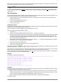
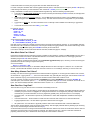
Intelligent Data Logging Products
DT80/80G
DT81
DT82E
DT85/85G
Series 1 & 2
Includes CEM20
User's Manual
A complete guide to:
data acquisition
data logging
programming
sensor wiring
communications
www.datataker.com
®
DT80 Series User’s Manual
© Copyright 2005-2010 Thermo Fisher Scientific Australia Pty Ltd ABN 52 058 390 917
UM-0085-B2
Warranty
Thermo Fisher Scientific Australia Pty Ltd (“Thermo Fisher”) warrants the instruments it manufactures against defects in
either the materials or the workmanship for a period of three years from the date of delivery to the original customer. This
warranty is limited to, and purchaser’s sole remedy for a breach of this warranty is, the replacement or repair of such defects,
without charge, when the instrument is returned to Thermo Fisher or to one of its authorized dealers pursuant to Thermo
Fisher’s return policy procedures.
The obligations set forth above shall be void with respect to any damage to the instrument resulting from accident, abuse,
improper implementation or use, lack of reasonable care, loss of parts, force majeure, or any other third party cause beyond
Thermo Fisher’s control. Any installation, maintenance, repair, service, or alteration to or of, or other tampering with, the
instruments performed by any person or entity other than Thermo Fisher without its prior written approval, or any use of
replacement parts not supplied by Thermo Fisher, shall immediately void and cancel all warranties with respect to the
affected instruments.
Thermo Fisher shall not be liable for any incidental, indirect, special, punitive or consequential loss or damages resulting
from or arising out of the use of the instrument, In no event shall Thermo Fisher’s liability with respect to the instrument, the
use thereof, this warranty statement or any cause of action related thereto, under any circumstances exceed the purchase
price of the instrument actually paid by purchaser.
Where Thermo Fisher supplies to the customer equipment or items manufactured by a third party, then the warranty
provided by the third party manufacturer shall pass through to purchaser, but only to the extent allowed by the original
manufacturer or third party supplier.
EXCEPT AS EXPRESSLY PROVIDED IN THIS WARRANTY STATEMENT, THERMO FISHER DISCLAIMS ALL OTHER
WARRANTIES, WHETHER EXPRESS OR IMPLIED, ORAL OR WRITTEN, WITH RESPECT TO THE INSTRUMENTS,
INCLUDING WITHOUT LIMITATION ALL IMPLIED WARRANTIES OF MERCHANTABILITY OR FITNESS FOR ANY
PARTICULAR PURPOSE. THERMO FISHER DOES NOT WARRANT THAT THE INSTRUMENTS ARE ERROR-FREE
OR WILL ACCOMPLISH ANY PARTICULAR RESULT. ANY ADVICE OR ASSISTANCE FURNISHED BY THERMO
FISHER IN RELATION TO THE INSTRUMENTS SHALL NOT GIVE RISE TO ANY WARRANTY OR GUARANTEE OF ANY
KIND, AND SHALL NOT CONSTITUTE A WAIVER BY THERMO FISHER.
The Purchaser shall be solely responsible for complying with all applicable local, state and Federal laws with respect to the
installation, use and implementation of the equipment.
Trademarks
dataTaker is a registered trademark of Thermo Fisher Scientific Australia Pty Ltd
Adobe® Flash® Player. Copyright © 1996 – 2006 Adobe Systems Incorporated. All Rights Reserved. Protected by U.S.
Patent 6,879,327; Patents Pending in the United States and other countries. Adobe and Flash are either trademarks or
registered trademarks in the United States and/or other countries.
All other brand and product names are trademarks or registered trademarks of their respective holders.
Related Software Products
dEX, DeTransfer, DeLoad, dataTaker ActiveX, dataTaker LabVIEWTM instrument driver
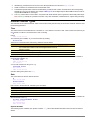
Important: Firmware Version Covered in This Manual
This version of the dataTaker DT80 Series User’s Manual (UM-0085-B2) applies to the DT80 range of data loggers (DT80,
DT80G, DT81, DT82E, DT85 and DT85G, Series 1 and Series 2) running Version 8.04 firmware.
WARNING
dataTaker products are not authorized for use as critical components in any life support system where failure of the product is
likely to affect the system’s safety or effectiveness.
Contents
Contents ......................................................................................................................3
Part A –
The DT80 ..................................................................................12
DT80 Concepts..........................................................................................................12
What is the DT80?.......................................................................................................... 12
The DT80 Product Family............................................................................................... 12
DT80-Friendly Software ................................................................................................. 13
About This Manual ......................................................................................................... 14
A Tour of the DT80's Interfaces...................................................................................... 14
Getting Started ............................................................................................................... 15
Sending Commands ....................................................................................................... 16
Getting Help ................................................................................................................... 16
Designing Your Data Logging System............................................................................ 16
Measurements...........................................................................................................17
What can the DT80 Measure?........................................................................................ 17
Analog Channels – Introduction ..................................................................................... 17
Digital Channels – Introduction....................................................................................... 19
Serial Channels – Introduction ....................................................................................... 20
Programming the DT80 ............................................................................................20
Typical Workflow ............................................................................................................ 20
USB memory devices ..................................................................................................... 22
Format of Returned Data..........................................................................................23
Real-time data ................................................................................................................ 23
Logged Data................................................................................................................... 24
Part B –
Channels ..................................................................................26
Channel Definitions ..................................................................................................26
Channel Numbers .....................................................................................................27
Channel Number Sequence ........................................................................................... 28
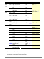
Channel Types ..........................................................................................................28
Internal Channel Types .................................................................................................. 31
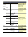
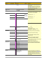
Channel Options .......................................................................................................35
Overview ........................................................................................................................ 35
A Special Channel Option — Channel Factor ................................................................ 35
Multiple Reports ............................................................................................................. 36
Mutually Exclusive Options............................................................................................. 36
Order of Application........................................................................................................ 36
Default Channel Options ................................................................................................ 37
Channel Option Table .................................................................................................... 38
Part C –
Schedules ................................................................................42
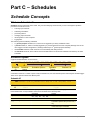
Schedule Concepts ..................................................................................................42
What are Schedules? ..................................................................................................... 42
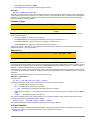
Schedule Syntax ............................................................................................................ 42
UM-0085-B2
DT80 Series User’s Manual
Page 3
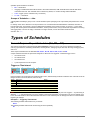
Types of Schedules ..................................................................................................45
General-Purpose Report Schedules (RA, RB,…RK)...................................................... 45
Special-Purpose Report Schedules................................................................................ 49
Immediate Report Schedules ......................................................................................... 49
Statistical Report Schedules........................................................................................... 50
Working with Schedules ..........................................................................................51
Entering Schedules into the DT80 (BEGIN–END).......................................................... 51
Triggering and Schedule Order ...................................................................................... 51
Changing a Schedule Trigger......................................................................................... 51
Halting & Resuming Schedules ...................................................................................... 52
Executing Commands in Schedules............................................................................... 52
Time Triggers — Synchronizing to Midnight................................................................... 52
Part D –
Jobs..........................................................................................54
What is a Job?................................................................................................................ 54
Entering a Job ................................................................................................................ 54
Loading an Existing Job ................................................................................................. 55
Job Structure .................................................................................................................. 55
Job Commands .............................................................................................................. 56
Startup Job ..................................................................................................................... 57
ONINSERT Job .............................................................................................................. 57
Part E –
Manipulating Data ...................................................................58
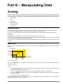
Scaling .......................................................................................................................58
Channel Factor............................................................................................................... 58
Spans (Sn) ..................................................................................................................... 58
Polynomials (Yn) ............................................................................................................ 59
Thermistor Scaling (Tn) .................................................................................................. 59
Intrinsic Functions (Fn) ................................................................................................... 60
Combining Scaling Options ............................................................................................ 60
Calculations ..............................................................................................................61
Channel Variables (nCV)................................................................................................ 61
Calculation Only Channels ............................................................................................. 62
Reference Channels....................................................................................................... 62
Expressions .................................................................................................................... 64
Combining Methods ....................................................................................................... 66
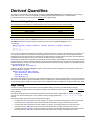
Derived Quantities ....................................................................................................67
Rates and Integrals ........................................................................................................ 67
Edge Timing ................................................................................................................... 67
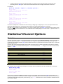
Statistical Channel Options .....................................................................................68
Overview ........................................................................................................................ 68
Statistical Functions ....................................................................................................... 69
Multi Value Statistical Options ................................................................................70
Histogram (Hx:y:m..nCV)................................................................................................ 70
Rainflow Cycle Counting ................................................................................................ 71
Part F –
Alarms ......................................................................................74
Alarm Concepts ........................................................................................................74
UM-0085-B2
DT80 Series User’s Manual
Page 4
Alarm Commands .....................................................................................................74
Alarm Number ................................................................................................................ 75
Alarm Condition .............................................................................................................. 75
Alarm Digital Action Channels ........................................................................................ 77
Alarm Action Text ........................................................................................................... 77
Alarm Action Processes ................................................................................................. 79
Alarm Records ..........................................................................................................82
Real Time Alarm Return ................................................................................................. 82
Logging Alarms .............................................................................................................. 82
Polling Alarm Inputs .................................................................................................83
Part G –
Logging and Retrieving Data .................................................84
Logging Data.............................................................................................................84
Enabling and Disabling Data Logging ............................................................................ 84
How Data and Alarms are Stored................................................................................... 84
Logging Options ............................................................................................................. 86
Factors Which May Prevent Logging.............................................................................. 86
Checking Logging Status ............................................................................................... 87
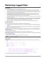
Retrieving Logged Data............................................................................................88
Overview ........................................................................................................................ 88
LISTD – List Available Data ........................................................................................... 88
COPYD – Unload Data................................................................................................... 92
DELD - Delete Logged Data........................................................................................... 99
Background Commands ............................................................................................... 100
Obsolete Commands.................................................................................................... 101
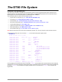
The DT80 File System.............................................................................................102
Internal File System (B:) ............................................................................................... 102
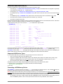
External USB Devices (A:) ........................................................................................... 103
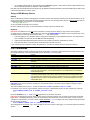
File Commands ............................................................................................................ 104
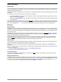
Data Recovery.............................................................................................................. 105
Part H –
DT80 Front Panel...................................................................106
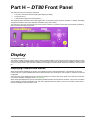
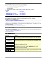
Display .....................................................................................................................106
Displaying Channels and Alarms.................................................................................. 106
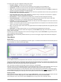
Bar Graph ..................................................................................................................... 107
Controlling what is shown on the display...................................................................... 108
Auto-scrolling................................................................................................................ 108
Auto-acknowledge ........................................................................................................ 108
Pop-up Messages ........................................................................................................ 108
Display Backlight .......................................................................................................... 109
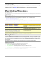
User Defined Functions.......................................................................................... 109
Defining Functions........................................................................................................ 109
Selecting Functions ...................................................................................................... 109
Default Functions ......................................................................................................... 109
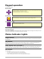
Keypad operation ...................................................................................................110
Special Key Sequences ............................................................................................... 110
Status Indicator Lights ...........................................................................................110
Sample Indicator .......................................................................................................... 110
UM-0085-B2
DT80 Series User’s Manual
Page 5
Disk Indicator................................................................................................................ 110
Power Indicator (not DT80 Series 1) ............................................................................ 110
Attn Indicator ................................................................................................................ 110
Part I –
Web Interface.........................................................................112
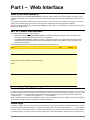
What is the Web Interface? .......................................................................................... 112
dEX vs. Classic Web Interface ..................................................................................... 112
Connecting to the Web Interface .................................................................................. 112
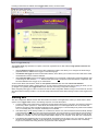
Home Page .................................................................................................................. 112
Starting dEX ................................................................................................................. 113
Browser Requirements ................................................................................................. 114
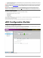
dEX Configuration Builder ..................................................................................... 114
Using the Configuration Builder.................................................................................... 114
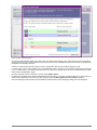
Defining Schedules ...................................................................................................... 116
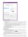
Defining Channels ........................................................................................................ 117
Global Settings ............................................................................................................. 121
Managing Configurations ............................................................................................. 121
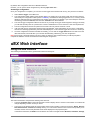
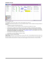
dEX Web Interface ..................................................................................................122
Using the Web Interface ............................................................................................... 122
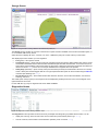
Status Screens ............................................................................................................. 123
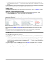
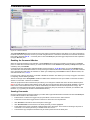
Data Retrieval............................................................................................................... 126
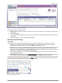
Displaying Real-Time Measurements........................................................................... 129
Command Window ....................................................................................................... 135
Help .............................................................................................................................. 136
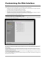
Customising the Web Interface ............................................................................. 137
Overview ...................................................................................................................... 137
The Web Interface Configuration Tool.......................................................................... 137
Status menu ................................................................................................................. 138
Retrieve menu .............................................................................................................. 138
Measurement menu ..................................................................................................... 138
Command menu ........................................................................................................... 138
Help menu .................................................................................................................... 139
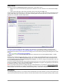
Branding ....................................................................................................................... 139
Security ........................................................................................................................ 140
Preventing Configuration Changes............................................................................... 140
Restoring Factory Settings ........................................................................................... 140
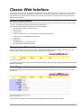
Classic Web Interface............................................................................................. 141
Browser Requirements ................................................................................................. 141
Navigating the Web Interface ....................................................................................... 141
Home Page .................................................................................................................. 141
Channels Page............................................................................................................. 142
Status Page.................................................................................................................. 142
Files Page .................................................................................................................... 143
Help Page..................................................................................................................... 143
Customising the Classic Interface ........................................................................ 144
Web Application Programming Interface (API)............................................................. 144
Server-Side Include (SSI) Directives ............................................................................ 144
Building A Custom Web Page ...................................................................................... 147
UM-0085-B2
DT80 Series User’s Manual
Page 6
Part J –
Modbus Interface...................................................................149
About Modbus .............................................................................................................. 149
Connecting to a Modbus Network ................................................................................ 149
Modbus Registers ........................................................................................................ 150
Putting It All Together ................................................................................................... 153
Part K –
Communications ...................................................................156
Overview..................................................................................................................156
Services........................................................................................................................ 156
Protocols ...................................................................................................................... 156
Physical Ports............................................................................................................... 157
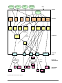
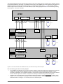
About the Communications Diagram............................................................................ 157
The Command Interface ......................................................................................... 159
Connecting to the Command Interface......................................................................... 159
Command Interface Operation ..................................................................................... 159
Detecting DT80 Presence ............................................................................................ 159
Password Protection .................................................................................................... 159
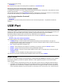
USB Port ..................................................................................................................160
Configuring the USB Port ............................................................................................. 160
About DtUsb ................................................................................................................. 160
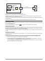
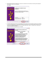
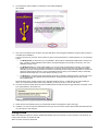
Installing DtUsb ............................................................................................................ 161
Using DtUsb ................................................................................................................. 164
Sleep Mode .................................................................................................................. 166
RS-232 Communications........................................................................................ 166
Direct RS-232 Connection............................................................................................ 166
RS-232 Flow Control .................................................................................................... 167
Sleep Mode .................................................................................................................. 167
Host RS-232 Port .................................................................................................... 168
Configuring the Host RS-232 Port ................................................................................ 168
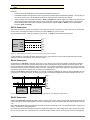
Serial Sensor Port...................................................................................................169
Connecting to the Serial Sensor Port ........................................................................... 169
Configuring the Serial Sensor Port ............................................................................... 171
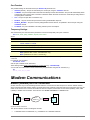
Modem Communications ....................................................................................... 172
Modem (Remote) RS-232 Connection ......................................................................... 172
Automatic Modem Detection ........................................................................................ 173
DT80-to-Modem Cable ................................................................................................. 173
Modem Initialisation...................................................................................................... 173
Powering the DT80’s Modem ....................................................................................... 175
Modem Communications Operation ............................................................................. 175
Setting Up a Remote Connection ................................................................................. 176
Ethernet Communications ..................................................................................... 177
TCP/IP Concepts.......................................................................................................... 177
Connecting to the DT80 Ethernet Port ......................................................................... 178
Ethernet Commands .................................................................................................... 180
How to set up Ethernet ................................................................................................. 181
Accessing the DT80 via the Internet............................................................................. 184
Using the Network Command Interface........................................................................ 186
Using the DT80 FTP Server ......................................................................................... 186
UM-0085-B2
DT80 Series User’s Manual
Page 7
PPP Communications.............................................................................................188
About PPP .................................................................................................................... 188
Setting up PPP ............................................................................................................. 188
Using PPP .................................................................................................................... 196
Part L –
Configuration.........................................................................198
Configuring the DT80 ............................................................................................. 198
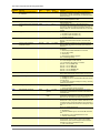
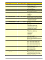
Parameters ................................................................................................................... 198
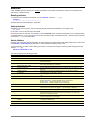
Switches ....................................................................................................................... 201
Profile Settings ............................................................................................................. 202
Setting the System Time .............................................................................................. 205
Automatic Time Adjustment (NTP) ............................................................................... 205
Resetting the DT80 ................................................................................................. 208
Soft Reset..................................................................................................................... 208
Hard Reset ................................................................................................................... 208
Safe Mode .................................................................................................................... 209
Factory Settings ........................................................................................................... 209
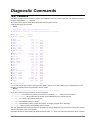
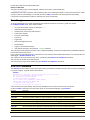
Diagnostic Commands ...........................................................................................210
TEST Command........................................................................................................... 210
Event Logs ................................................................................................................... 211
STATUS Command...................................................................................................... 211
CHARAC Command..................................................................................................... 212
SERVICEDATA Command........................................................................................... 212
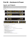
Part M –
Hardware & Power.................................................................213
Inputs and Outputs .................................................................................................213
DT80 Wiring Panel ....................................................................................................... 213
DT80 Front Panel ......................................................................................................... 214
DT80 Side Panel .......................................................................................................... 214
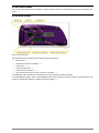
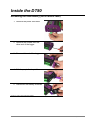
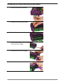
Inside the DT80 ....................................................................................................... 215
Accessing the main battery (not DT80G/DT82E) ......................................................... 215
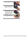
Accessing the lithium memory backup battery ............................................................. 216
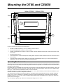
Mounting the DT80 and CEM20 .............................................................................218
Dimensions................................................................................................................... 218
Operating Environment ................................................................................................ 218
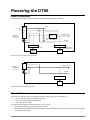
Powering the DT80 ................................................................................................. 219
Power Subsystem ........................................................................................................ 219
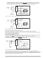
External Power ............................................................................................................. 219
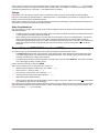
Internal Power (not DT82E).......................................................................................... 220
Power Outputs (DT80/82E Series 2 and DT85) ........................................................... 222
Internal Memory-Backup Battery .................................................................................. 223
Monitoring DT80 Power................................................................................................ 223
Power Consumption ...............................................................................................224
Power Consumption ..................................................................................................... 224
Battery Life ................................................................................................................... 227
Minimising Power Consumption ................................................................................... 228
Sleep Mode..............................................................................................................229
About Sleep Mode ........................................................................................................ 229
UM-0085-B2
DT80 Series User’s Manual
Page 8
Wake Events ................................................................................................................ 229
Controlling Sleep .......................................................................................................... 230
Forced Sleep Mode ...................................................................................................... 230
Part N –
Sensors & Channels.................................................................231
Analog Channels ....................................................................................................231
About the Analog Input Terminals ................................................................................ 231
Voltage ......................................................................................................................... 232
Current ......................................................................................................................... 235
4–20mA Current Loops ................................................................................................ 237
Resistance.................................................................................................................... 237
Bridges ......................................................................................................................... 240
Temperature – Thermocouples .................................................................................... 244
Temperature – Thermistors .......................................................................................... 246
Temperature – RTDs.................................................................................................... 247
Temperature – AD590 Series IC Sensors .................................................................... 248
Temperature – LM35 Series IC Sensors ...................................................................... 249
Temperature – LM135 Series IC Sensors .................................................................... 250
Humidity Sensors ......................................................................................................... 251
Frequency .................................................................................................................... 252
Strain Gauges – Bridge ................................................................................................ 252
Strain Gauges – Vibrating Wire .................................................................................... 253
Strain Gauges – Carlson Meter .................................................................................... 255
Analog Logic State Inputs ............................................................................................ 258
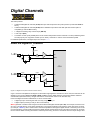
Digital Channels......................................................................................................259
About the Digital I/O Channels ..................................................................................... 259
Digital Inputs................................................................................................................. 260
Digital Outputs .............................................................................................................. 261
Counters – Low Speed ................................................................................................. 265
Counters – High Speed ................................................................................................ 266
Phase Encoders ........................................................................................................... 268
Examples – Digital and Counters ................................................................................. 269
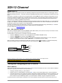
SDI-12 Channel .......................................................................................................270
About SDI-12................................................................................................................ 270
Testing and Configuring an SDI-12 Device .................................................................. 270
Reading Data from SDI-12 Devices ............................................................................. 271
Example ....................................................................................................................... 272
Other Considerations ................................................................................................... 273
Troubleshooting............................................................................................................ 273
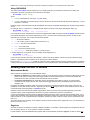
Generic Serial Channel........................................................................................... 275
Connecting to and Configuring the Serial Port ............................................................. 275
Serial Channel Commands .......................................................................................... 275
Serial Channel Operation ............................................................................................. 276
Control String – Output Actions .................................................................................... 278
Control String – Input Actions....................................................................................... 280
Control String – Example ............................................................................................. 282
Schedules..................................................................................................................... 283
Serial Sensor Direct Mode............................................................................................ 284
Serial Interface Power Control...................................................................................... 284
Serial Channel Debugging Tools.................................................................................. 285
UM-0085-B2
DT80 Series User’s Manual
Page 9
Serial Channel Examples ............................................................................................. 285
Modbus Channel .....................................................................................................288
About Modbus .............................................................................................................. 288
Connecting Serial Modbus Sensors ............................................................................. 288
Connecting Network Modbus Sensors ......................................................................... 289
Reading Data from Modbus Devices............................................................................ 290
MODBUS Channel Options .......................................................................................... 291
Block Transfers ............................................................................................................ 292
Examples...................................................................................................................... 292
Troubleshooting............................................................................................................ 293
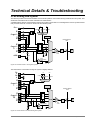
Technical Details & Troubleshooting.................................................................... 294
DT80 Analog Sub-System ............................................................................................ 294
Grounds, Ground Loops and Isolation ......................................................................... 298
Noise Pickup ................................................................................................................ 299
Self-Heating of Sensors ............................................................................................... 299
Getting Optimal Speed from Your DT80....................................................................... 299
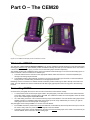
Part O –
The CEM20 .............................................................................300
What is the CEM20? .................................................................................................... 300
Connecting CEM20s .................................................................................................... 300
CEM20 Addresses ....................................................................................................... 302
Powering the CEM20 ................................................................................................... 302
Accessing CEM20 Channels ........................................................................................ 302
CEM20 Temperature Reference .................................................................................. 303
Troubleshooting............................................................................................................ 303
Part P –
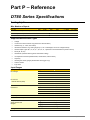
Reference ...............................................................................304
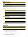
DT80 Series Specifications ....................................................................................304
Analog Inputs ............................................................................................................... 304
Digital Inputs and Outputs ............................................................................................ 305
High Speed Counter Inputs .......................................................................................... 306
Serial Channels ............................................................................................................ 306
Data Manipulation and Logging.................................................................................... 307
Communication Interfaces............................................................................................ 307
Network (TCP/IP) Services........................................................................................... 308
System ......................................................................................................................... 308
CEM20 Specifications.............................................................................................310
Command Summary ...............................................................................................311
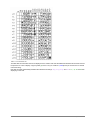
ASCII-Decimal Tables ............................................................................................. 314
RS-232......................................................................................................................317
Signals.......................................................................................................................... 317
Cables .......................................................................................................................... 317
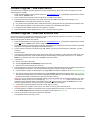
Upgrading DT80 Firmware ..................................................................................... 319
Recommended Preparation ......................................................................................... 319
Firmware Upgrade – USB Flash Device....................................................................... 320
Firmware Upgrade – Host USB or RS232 Port ............................................................ 320
Firmware Upgrade – Remote TCP/IP........................................................................... 321
Reverting Back to Old Firmware................................................................................... 321
UM-0085-B2
DT80 Series User’s Manual
Page 10
In Case of Failed Upgrade ........................................................................................... 321
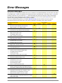
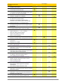
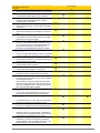
Error Messages.......................................................................................................322
Standard Messages ..................................................................................................... 322
Data Errors ................................................................................................................... 326
DT80 Abnormal Resets ................................................................................................ 326
Glossary ..................................................................................................................327
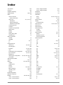
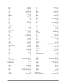
Index ........................................................................................................................337
UM-0085-B2
DT80 Series User’s Manual
Page 11
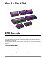
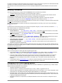
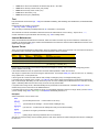
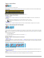
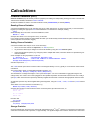
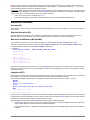
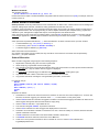
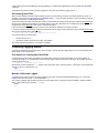
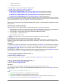
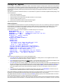
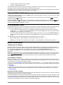
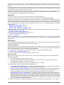
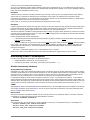
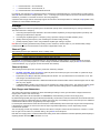
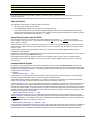
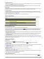
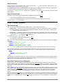
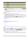
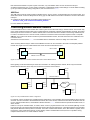
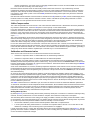
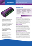
Part A – The DT80
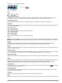
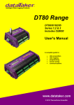
Figure 1: The dataTaker DT80G, DT80 and DT81 (rear), DT85G and DT85 (centre), DT82E and CEM20 (front)
DT80 Concepts
What is the DT80?
The dataTaker DT80 range of data acquisition and logging instruments are tools to measure and record a wide variety of
quantities and values in the real world.
The web based dEX graphical user interface makes it quick and easy to define basic measurement tasks. Logged data can
then be easily extracted via a USB "memory stick", or downloaded using the web interface into files ready for import into
spreadsheets and data analysis tools.
The DT80 range of loggers also include a powerful programming language which allows complex systems to be developed
and monitored.
Extensive sensor support and communications options, and a rugged and low-power design, make the DT80 a very flexible
data logger.
The DT80 Product Family
The DT80 product family includes the following models:
The DT80 is a full-featured data logger,
The DT81 is a lower cost variant of the DT80.
The DT82E is a low cost, low power logger designed for environmental applications.
The DT85 is an expanded and enhanced version of the DT80.
The DT80G and DT85G GeoLoggers are designed for Geotechnical applications.
The CEM20 (Channel Expansion Module) is a 20-channel analog multiplexer which can be used to expand the
number of analog input channels on a DT80/80G or DT85/85G.
UM-0085-B2
DT80 Series User’s Manual
Page 12
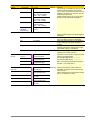
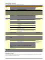
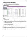
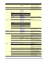
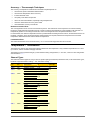
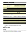
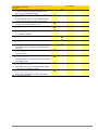
The DT80/80G, DT81, DT82E and DT85/85G loggers all operate in a very similar way. The main differences are as follows:
Feature
DT81
DT82E
DT80 / DT80G
DT85 / DT85G
Analog input channels
Digital I/O channels (open-drain outputs)
Digital I/O channels (logic outputs / SDI-12)
Dedicated RS232/422/485 serial sensor port
Phase encoder inputs
Switched 12V power output
Unswitched external power output
LCD display & keypad
USB communications port
Battery charger for internal/external battery
Internal battery
Modbus master function
1
3
1
1
yes
yes
yes
-
2
3
1
yes
yes
-
5
4
4
yes
2
yes
yes
yes
yes (not DT80G)
yes
16
4
4
yes
2
yes
yes
yes
yes
yes
yes
yes
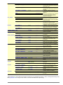
Series 1 and Series 2
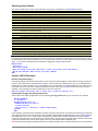
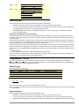
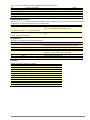
In January 2008, the original DT80, DT81 and DT85 models were superseded by enhanced Series 2 models. The main
differences between the models are as follows:
Feature
Fully isolated analog input pairs (+- and *#
terminals switched independently)
Switched 12V power output
Unswitched external power output
Status LEDs
Classic web interface (HTML)
dEX Enhanced web interface (Flash)
DT81
Series 1
DT81
Series 2
DT80
Series 1
DT80/80G
Series 2
DT85
Series 1
DT85/85G
Series 2
-
yes
-
yes
yes
yes
4
yes
-
yes
4
yes
yes
3
yes
-
yes
4
yes
yes
yes
yes
4
yes
-
yes
yes
4
yes
yes
Series 2 units are clearly labelled as such on the front panel.
Note that all DT82E units are Series 2.
GeoLoggers
The DT80G and DT85G "GeoLoggers" are equivalent to the DT80 and DT85, but also include direct support for vibrating
wire strain gauges, which are widely used in geotechnical applications; see Strain Gauges – Vibrating Wire (P253).
Throughout this manual, references to the DT80 and DT85 also refer to the DT80G and DT85G respectively, unless
otherwise noted.
Channel Expansion Module
The CEM20 is an analog multiplexer designed to work with a DT80 or DT85 Series 2 logger. It provides an easy way to
expand the number of input channels. Up to 15 CEM20 modules can be connected to a DT85, giving a total of 300 input
channels. See The CEM20 (P300).
Note: In this manual, the term DT80 (italics) is used to refer to all products (DT80, DT81 and DT85; Series 1 and Series 2).
If a feature or behaviour is specific to a particular model, this will be made clear in the text.
DT80-Friendly Software
Programming and Configuration
There are three main ways to set up and program the DT80.
dEX is a web based application for programming and monitoring DT80 Series 2 data loggers. dEX is built into the
logger (no installation required) and runs in your web browser. It provides a totally graphical interface, which means
that knowledge of the dataTaker programming language is not required. Channels and schedules are defined simply
by clicking on icons and making selections from menus and dialog boxes; dEX will then generate the required DT80
program and load it onto the logger.
Alternatively, commands entered interactively and then sent to the DT80 via one of its comms ports or a TCP/IP
network. This allows full access to the DT80's capabilities. DeTransfer, or the enhanced web interface's command
window, are the best tools for the job here. They both have separate send and receive windows, a macro facility, and
many other useful features. A standard terminal program (e.g. HyperTerminal) can also be used.
Finally, you can develop a DT80 program off-line (e.g. using a text editor), then transfer it to the DT80 using a USB
memory device or send it as a file using DeTransfer. DeLoad is a Windows based application which allows a
pre-written program to be transferred to the logger using a simple "drag and drop" operation.
UM-0085-B2
DT80 Series User’s Manual
Page 13
Viewing Data and Status
Once the DT80 has been set up, there are a number of options for retrieving data and monitoring status:
The DT80's inbuilt web interface (dEX) provides a convenient way to access current data values and status
information from any web browser. dEX is available on all Series 2 loggers.
A simple HTML-based web interface is also provided on all loggers. This can be customised if required to provide an
application-specific user interface. This interface is designed to operate efficiently on slow communications networks
or on portable devices with a small display screen.
DeTransfer can be used to view real-time and logged data in text format.
DeLoad provides an easy way of collecting logged data, which can then be saved or sent by email.
dataTaker Instrument driver for LabVIEW™ is a set of drivers and documentation which allows dataTaker data
loggers to be incorporated in a LabVIEW environment. LabVIEW is National Instruments' industry-leading graphical
software development environment for measurement and automation applications.
All software is provided on the CD supplied with your DT80, and updates are available from the Datataker website,
www.datataker.com (Support/Downloads section).
About This Manual
This manual is intended for all users of the DT80. It describes:
how to connect sensors and other devices to the DT80's input and output channels.
how to program the DT80 to collect and return data as required.
how to manage the data that the DT80 collects.
The main focus of this manual will be on directly programming the DT80 using its command language. However, most of the
concepts discussed here also apply when building programs using tools such as dEX.
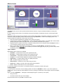
A Tour of the DT80's Interfaces
The DT80's interfaces with the outside world are grouped into three main areas: user interface (top), sensor interface (front)
and communications interface (side). See also Inputs and Outputs (P213).
User Interface
On the top panel of the DT80 you will find controls which allow the user to interact with the unit during operation – without
requiring a host computer:
A 2-line LCD display shows status messages, measured values, and a menu of pre-defined functions (not DT81)
Six keypad buttons allow the user to navigate between the various displayed options (not DT81)
Four status LEDs are provided – the blue Sample LED flashes each time a measurement is taken, the green Disk
LED indicates internal flash disk activity, the red Attn LED indicates various warning conditions, and the green Power
LED flashes at 3 second intervals while the logger is powered and not in low "sleep" mode. The duty cycle of the flash
indicates whether the logger is externally powered (long flashes) or running from its internal battery (short flashes).
(Note that the Power LED is not present on DT80 Series 1.)
A USB socket allows connection of a USB memory device, which provides a convenient way to retrieve data from the
DT80 (or load a program onto it)
Sensor Interface
On the sloping front panel of the DT80 there are two rows of terminal blocks – digital channels on the left, analog channels on
the right. The green terminal blocks can be quickly unplugged from the DT80 without unscrewing the sensor cabling.
This interface includes:
8 digital input/output/counter channels (1D – 8D), 4 of which are SDI-12 compatible (DT81/82E: 4 channels, one of
which is SDI-12 compatible)
an input to wake the DT80 from low power "sleep" mode (WK)
4 counter inputs (or two phase encoder inputs) (1C – 4C) (one phase encoder input on DT81, none on DT82E)
a pair of voltage free relay contact outputs (RELAY A and B)
a general purpose switched 12V 150mA power output (12V) (DT80/81/82E Series 2 and DT85 only)
a general purpose current limited (300mA) power output (PWR OUT), which is derived from the external power input
(DT85 only)
an RS232/422/485 compatible serial port (Tx, Rx, RTS and CTS) (not present on DT81/82E)
digital / power ground terminals (DGND)
a number of analog input channels (5 channels for DT80, 1 channel for DT81, 16 channels for DT85)
an external excitation input (EXT *)
isolated analog ground terminals (AGND on DT80/81, EXT# on DT80 Series 2 and DT85)
UM-0085-B2
DT80 Series User’s Manual
Page 14
(Note that early production DT80 models only had 4 analog inputs.)
Communications/Power Interface
On the left side panel you have a variety of connectivity options:
10-Base-T Ethernet for connection to a host computer or local area network
USB for high speed connection to a host computer (not present on DT82E)
RS232 for connection to host computer or modem
two alternative DC power connectors – a standard plug-pack socket (DC jack) and a 4-pin terminal block (2-pin for
DT82E)
For more details, see Communications (P156)
A threaded earth point is also available on both left and right side panels.
Getting Started
Power
Powering the DT80(P219) discusses the ways to provide power to the DT80. The simplest option is to plug in the supplied AC
adaptor.
All DT80 models except the DT82E include an internal 6V lead-acid battery which can power the logger if the main external
supply is interrupted.
Important The DT80 is shipped with its main internal battery disconnected. We recommend the battery is connected as
soon as practical so that it can charge from the mains adaptor or other external power source. This is achieved by simply
plugging the green power connector, see Powering the DT80 (P219).
Switch On!
When power is connected, you should observe:
the LCD backlight switches on (DT80/85), and the green Power LED starts flashing (DT81/85 and DT80 Series 2)
a brief clicking sound as the unit performs an initial self-calibration
DT80 restarted / Power loss is displayed on the LCD
the front panel LEDs flash a few times then the red Attn LED continues to flash.
The DT80 is warning you that its power has been interrupted. Press any of the front panel keys (or send the command
CATTN) to clear this indication. The Attn LED should stop flashing and the display should now read: DT80 V8.00 / No
current job. This indicates that:
the version of DT80 firmware in use is "8.00" (this number may vary), and
no user program (or "job") has been loaded
The DT80 is now idle and waiting for instructions.
Connecting to a Host Computer
In order to program the DT80, it is generally necessary to connect it to a "host" computer. The easiest option here is to use
the supplied USB cable, or, for the DT82E, the supplied Ethernet cable. Other options are to use a "null-modem" (cross-over)
RS232 cable, or to connect the logger to an Ethernet network. See Communications (P156) for more details of the different
communications options.
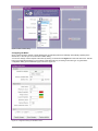
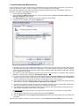
Very briefly, connecting the DT80 via USB involves the following steps:
1.
Install the supplied DtUsb driver software. This allows you to access to DT80's network services via a USB
connection.
2.
Connect the USB cable between the DT80 and the PC.
3.
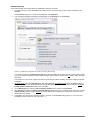
The Windows "New Hardware Found" wizard will then run automatically (if required) to complete the installation of the
necessary drivers.
4.
Your default web browser will then be launched automatically and the dEX home page will be displayed.
To connect to the DT80 using Ethernet:
1.
Connect the Ethernet cable between the DT80 and the PC, or between the DT80 and a socket on your computer's
local area network.
2.
Use the DT80 keypad to scroll down to the "Ethernet" screen. Check that a valid IP address is displayed, e.g.
169.254.3.202
3.
Launch your web browser and type the logger's IP address into the address bar. The dEX home page should be
displayed.
The above is only an brief overview. See USB Port (P160) or Ethernet Communications (P177) for detailed, step by step
instructions.
As an alternative to the dEX web-based interface, you can also install the supplied DeTransfer software, which can be used
UM-0085-B2
DT80 Series User’s Manual
Page 15
to send the text-based commands described in this manual to the logger. DeTransfer can operate over a direct RS2323/USB
connection or a network connection, and will work with Series 1 or Series 2 loggers.
The remainder of this manual will assume you have successfully established a connection between the host PC and the
DT80.
Sending Commands
The DT80 is programmed by sending it textual commands. These commands may be either:
manually entered (using DeTransfer, or the Command screen in dEX), or
generated by the dEX configuration builder, based on details entered using its graphical user interface controls.
Commands are executed by the DT80 only after it receives a carriage-return character ().
Commands are not case-sensitive; that is, they may be entered using either uppercase or lowercase characters.
In this manual all commands are shown in UPPERCASE. Responses from the DT80 are shown like this.
After receiving a command, the DT80 will normally echo the command, after converting it to uppercase. Note that the DT80
does not echo each character as it is received.
After a command has been processed, the DT80 will normally indicate that it is ready for the next one by transmitting a
prompt string, such as:
DT80>
(Command echo and the prompt string can be turned off if required using the /e switch command, see Switches (P201).)
The maximum length of a command is 255 characters.
The general categories of commands are:
channel definitions (P26) (e.g. 2TK("Kiln temp",FF4)) – these define what measurements are to be taken,
how they are to be acquired and how the measured values are to be presented.
schedule definitions (P42) (e.g. RA(DATA:2MB)10S) – these define when a set of measurements are to be taken
and where the results are to be stored
job management commands (P56) (e.g. BEGIN, END, SHOWPROG) – these allow a set of schedule and channel
definitions to be grouped into a single program, or "job", which can then be treated as a unit.
data management commands (P88) (e.g. COPYD, LISTD) – these allow logged data points and alarms to be
retrieved, displayed or deleted.
configuration commands (P198) (e.g. PROFILE) – these allow various aspects of the DT80's operation to be
adjusted to suit particular requirements.
Jobs (sets of commands) are stored in the DT80's internal file system along with the data they generate. Different jobs can
be loaded under manual or program control. In addition, the DT80 can automatically run a particular job every time it is reset
or powered up. See Startup Job (P57).
Getting Help
There are several options for getting help with programming the DT80:
The command HELP topic will display useful summary information on a number of topics. Type HELP by itself to
display a list of available topics. For example, HELP COMMANDS will display a list of DT80 commands.
This user manual, firmware release notes and a list of known issues are automatically installed onto the DT80's
internal file system each time a firmware upgrade is done. In this way you always have access to up-to-date
documentation for the installed firmware version. The easiest way to view these is via the DT80's built-in web
interface.
The Datataker website (www.datataker.com) contains an extensive database of frequently asked questions, code
examples, sensor information, application notes, video tutorials and an online forum.
Designing Your Data Logging System
Data acquisition and data logging are orderly processes and should be undertaken in a systematic way. In order to obtain
effective information efficiently, do the following:
Identify the quantities to be measured.
Select the sensors, considering measurement range, accuracy, stability, ruggedness and cost.
Select the wiring configuration. For example, resistive sensors can be connected in 2, 3 or 4 wire configuration, while
serial sensors can use different electrical standards (RS232/RS485 etc.) and data rates.
Determine sensor output scaling, that is, the relationship between sensor output voltage/current/resistance/etc. and
the actual quantity. For many sensor types this calculation is performed automatically by the DT80 – all you need to do
is specify the appropriate channel type.
Determine how data is to be processed, for example statistical functions such as max/min or histograms may be
required.
UM-0085-B2
DT80 Series User’s Manual
Page 16
Decide on the sample frequency – don't sample faster than you need to.
Calculate the volume of data to be collected.
Decide on the method of data recovery and archiving – real-time data return or logging or both? Will logged data be
unloaded via a comms port, or collected using a USB memory device, or transmitted to an FTP site? How often?
Decide on an appropriate communications technology for setup/maintenance and normal operation: RS232, USB,
Ethernet, modem, none?
Consider the power consumption, including the use of low power “sleep” mode. In the event of a power failure will the
DT80’s internal battery provide adequate running time?
The remainder of this manual will help you address these questions and then generate a suitable program for your DT80.
Measurements
What can the DT80 Measure?
Analog
Using its analog inputs, the DT80 can directly measure the following:
DC voltage (30mV, 300mV, 3V and 30V ranges)
DC current (0.3mA, 3mA and 30mA ranges)
resistance (10Ω, 100Ω, 1kΩ, 10kΩ ranges)
frequency (0.1 to 10,000 Hz)
Many other quantities can be measured by connecting appropriate sensors which convert a physical quantity into
something that the DT80 can measure. The DT80 directly supports:
4-20mA current loop sensors (0 to 100%)
temperature sensors (thermocouples, RTDs, thermistors, IC sensors)
bridges and strain gauges
vibrating wire strain gauges (DT80G/85G only)
This list can be extended by means of user specified scaling calculations.
Digital
The DT80’s digital and counter channels allow the measurement of:
digital input state (contact closure or TTL logic)
pulse count (32 bit)
phase encoder position (32 bit)
Serial
Various “smart sensors” can also be read:
SDI-12 (Serial Data Interface – 1200 baud) based sensor networks
other serial sensor devices with an RS232/422/485 interface, such as weighing machines, barcode scanners
CAN (Controller Area Network) sensors, using the optional dataTaker CANgate CAN to ASCII gateway device. The
use of this product is outside the scope of this manual.
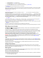
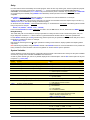
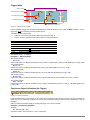
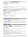
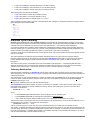
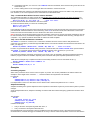
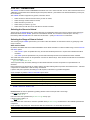
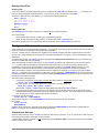
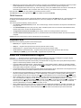
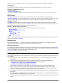
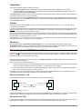
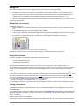
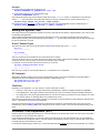
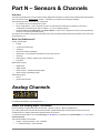
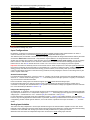
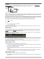
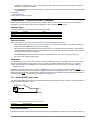
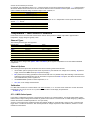
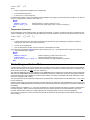
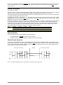
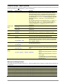
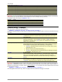
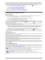
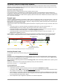
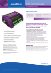
Analog Channels – Introduction
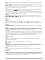
* +1- # * +3- # * +5- #
* +2- # * +4- # * # * #
EXT EXT EXT EXT
ANALOG
RELAY
Figure 2: DT80 analog terminals
Input Terminals
The DT80 provides five analog input channels, numbered 1 to 5. Depending on the wiring configuration used, these allow
between 5 and 15 separate voltages to be measured. The DT81 has one analog input channel, allowing 1-3 separate
voltages to be measured, and the DT82E has two (2-6 separate voltage measurements). Finally, the DT85 has 16 analog
UM-0085-B2
DT80 Series User’s Manual
Page 17
input channels, allowing 16-48 separate voltage measurements.
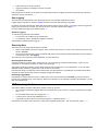
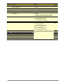
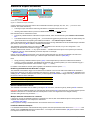
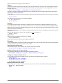
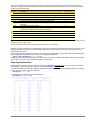
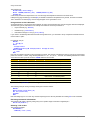
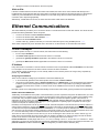
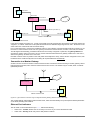
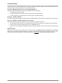
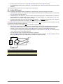
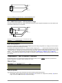
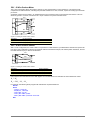
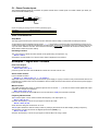
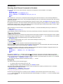
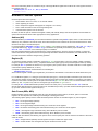
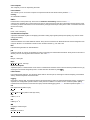
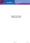
Each analog input channel on a DT80 is a 4-wire connection (see Figure 3) that allows voltage, current, resistance and
frequency to be measured. These are the fundamental signals output by most sensors. It is not necessary to use all four
terminals on each channel— two are often adequate.
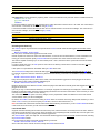
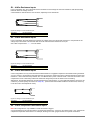
Excite Terminal
Positive Terminal
Negative Terminal
Return Terminal
Figure 3: Analog input channel terminal labels
The exact function of each terminal varies depending on how the channel is programmed. In general terms:
The * ("Excite") terminal can be a voltage input (relative to # terminal), or it can provide sensor excitation (for example,
for resistance measurement) See Sensor Excitation (P19).
The + ("Plus") terminal is a voltage input (relative to – or # terminal)
The – ("Minus") terminal is a voltage input (relative to # terminal)
The # ("Return") terminal is normally used as a common or return terminal. It can also be used as a current input, using
the DT80's internal shunt resistor.
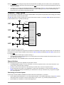
Multiplexers
The DT80's analog input channels are multiplexed. The required input terminals are first connected to the input of the
DT80's instrumentation amplifier and analog to digital converter, then a measurement is taken. The next channel to be
sampled is then switched through to the amplifier and ADC, and so on. Simultaneous sampling of analog channels is not
possible.
Channel definition commands in the DT80 program determine which terminals are used for a particular measurement. For
example, the channel definition 1+V measures the voltage between the + and # terminals on channel 1.
Gain Ranges and Attenuators
The DT80's instrumentation amplifier has three switchable gain settings. These give three basic voltage measurement
ranges (3V, 300mV and 30mV full scale)
The DT80’s default is for its instrumentation amplifier to automatically change gain range to suit the input signal applied to it
by the multiplexers.
If the amplitude of your input signals are known, then the gain can be set manually. Do this by applying the GLx (gain lock)
channel option, which disables autoranging for that channel and sets the gain to a fixed range.
The analog inputs also include switchable 10:1 attenuators, which effectively provide a fourth range (30V).
Warning Maximum input voltage on any analog input is ±35V dc, relative to the AGND/EXT# terminal. If this is exceeded
then permanent damage may occur.
Analog Input Configurations
The basic quantity that the DT80 measures is voltage. Voltages can be measured using two different input configurations:
shared-terminal analog inputs
independent analog inputs
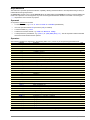
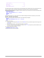
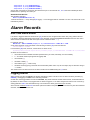
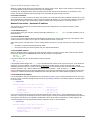
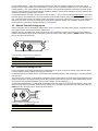
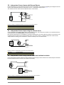
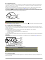
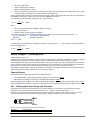
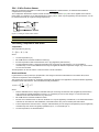
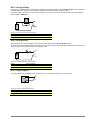
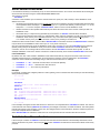
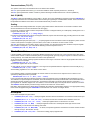
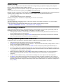
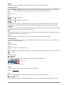
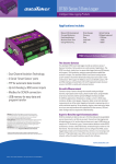
Shared-Terminal Analog Inputs
Sometimes called "single-ended" inputs, a shared-terminal input is one that shares one or more of its terminals with another
input. In Figure 4, the three sensors share channel 1’s # terminal. Each of the three inputs is a shared-terminal input.
Figure 4 Shared-terminal voltage inputs sharing a channel’s # terminal (voltage inputs used as example)
UM-0085-B2
DT80 Series User’s Manual
Page 18
In a shared-terminal configuration, a sensor’s "return" or "negative" wire is usually connected to the channel's # terminal. The
remaining sensor wire (the "positive" or "signal") is connected to any of the channel’s other three terminals. The common
terminal need not be at ground potential – all voltage measurements (shared or unshared) are differential, i.e. only the
difference in voltage between the two terminals is reported.
For shared-terminal inputs, the channel number is given a suffix indicating the terminal to which the positive wire is
connected. For example, a shared-terminal voltage input applied to channel 1 between the + and # terminals is recognized
by the channel definition 1+V.
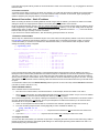
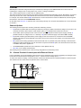
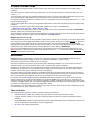
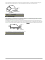
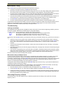
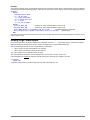
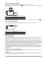
Independent Analog Inputs
An independent input (also known as an "unshared" input) is one that connects to its own terminals and does not share any
of those terminals with any other inputs. For example, in Figure 5, sensor A is connected to channel 1’s + and – terminals,
and sensor B is connected to the other two terminals of the channel. In other words, each sensor’s terminals are independent
of the other’s — no terminal is used by both sensors.
Figure 5 Wiring one or two independent inputs to a single channel (voltage inputs used as example)
Note that each analog input channel can support two independent voltage inputs. In the above example, the channel
definition 1V will read sensor A while 1*V will read sensor B. The channel definition syntax is fully described in Channels
(P26)
Sensor Excitation
Many sensors require excitation (electrical energy) so that they can provide an output signal. For example, to read the
temperature of a thermistor, excitation current is passed through the thermistor to generate a voltage drop that can be
measured.
The DT80 can provide
Voltage source of approx. 4.5V via 1kΩ. Useful for powering some sensors however the supply is not regulated and
consequently liable to drift with temperature
200μA (approx.) current source. Default excitation for resistance measurement. Very stable over environmental
temperature range.
2.5mA (approx.) current source. Default excitation for RTD and bridge measurement. Very stable over environmental
temperature range.
User supplied external excitation EXT* terminal. The user can provide an external excitation which is appropriate to
the sensor being used. (The DT80 Series 2 and DT85 provide two general purpose DC power outputs which may be
connected to the EXT* terminal to provide external excitation if required.)
See the Excitation category in the Table 3: DT80 Channel Options (P41) table.
More Information
For full details on how to connect sensors and make measurements using the DT80's analog inputs, see Analog Channels
(P231).
D WK 12V
1D 2D 3D 4D GND
D
5D 6D 7D 8D GND
1
3
1C 2C 3C 4C D
Tx Rx RTS CTS D
Z A Y B GND
2
4
1PE
2PE
GND
RELAY
A B
5
ANALOG
DIGITAL
Digital Channels – Introduction
Figure 6: DT80 digital terminals
The DT80 provides:
4 bidirectional digital I/O channels (1D-4D) with open drain output driver and pull-up resistor (DT81/82E: 3 channels,
1D-3D)
4 bidirectional digital I/O channels (5D-8D) with tri-stateable output driver and weak pull-down resistor. These
channels may also be used for controlling intelligent sensors using the SDI-12 protocol (DT81/82E: 1 channel, 4D)
1 voltage free latching relay contact output (RELAY)
UM-0085-B2
DT80 Series User’s Manual
Page 19
1 LED output (Attn)
4 hardware counter inputs (1C-4C) which can be used as independent counter channels or as two quadrature (phase
encoder) inputs (DT81: one phase encoder input, shared with inputs 3C and 4C. There are no phase encoder inputs
on the DT82E.)
As with analog channels, channel definition commands are used to specify which digital inputs are to be measured and/or
what digital output states are to be set. For example, the command 1DS will read the digital state (0 or 1) on channel 1D,
while 3DSO=0 will set channel 3D low.
A transition on a digital channel can be used to trigger a schedule. This allows a series of measurements to be made (or
commands executed) in response to a change in digital state.
The DT80 can count the number of pulses received on any digital input. The four dedicated counter inputs provide additional
capabilities:
a higher maximum count rate
the ability to keep counting even if the logger is in low-power "sleep" mode
optional low-level (5mV) input threshold levels
optional decoding of phase-encoded input signals
For more details, see Digital Channels (P259)
Serial Channels – Introduction
The DT80 supports two main classes of "smart sensor":
A wide range of sensors, particularly in the environmental monitoring field, use the SDI-12 protocol. The DT80 fully
supports this protocol making it a simple process to read measured values. See SDI-12 Channel (P270).
The DT80 also provides a generic serial channel.
The serial channel allows a wide variety of sensors and devices to be controlled and polled. The serial channel:
can use the dedicated serial sensor port (not DT81/82E), the host RS232 port, and/or the USB port
supports USB, RS232, RS422 and RS485 signal levels (depending on the port)
supports point-to-point or multi-drop operation (point-to-point only for the host/USB port)
features programmable output (poll) strings and a variety of options for parsing returned data
can trigger execution of a schedule in response to received data
For more details, see Generic Serial Channel (P275).
Programming the DT80
Typical Workflow
When creating a program to send to the DT80, typically the work will follow this order:
Connect Sensors
Sensors & Channels (P231) describes how to measure many different quantities and read many different sensor types using
the DT80’s analog, digital and serial inputs.
The first step is therefore to refer to the sub-section relating to the quantity you wish to measure. This will help you decide on
the most appropriate way to connect the sensor to the DT80.
Define Channels
Programming the DT80 essentially consists of :
defining a series of measurements to take, and
specifying when to take them.
Each measurement definition is referred to as a channel. It is important to be clear on how the word “channel” is used – in
DT80 parlance, it refers to a measurement to be made, not a physical input channel.
For example, if you program the DT80 to measure a voltage on analog input 1, then read the state of digital input 3, then
measure the voltage on analog input 1 again then you have defined three channels. The fact that the first and third channels
both measure the same physical quantity (the voltage on analog input 1) is irrelevant – as far as the DT80 is concerned, they
are two entirely separate measurements.
To specify when measurements are to be made, channel definitions may be grouped into schedule definitions. These
specify whether the channels should be sampled immediately, or periodically, or in response to some event.
To define a channel, you need to specify:
UM-0085-B2
DT80 Series User’s Manual
Page 20
the input number (e.g. 1 for analog input 1)
the channel type (e.g. V to perform a voltage measurement)
any channel options that may be required (listed in parentheses, e.g. (GL3V,FF3)
So to define the three channels mentioned above, you could enter:
1V 3DS 1V
Since we haven’t specified any schedule, these three measurements will be taken immediately, one after the other. Default
settings will be used, since no channel options were specified. By default, the DT80 will then return the measured values in
ASCII form to the host computer, e.g.
1V 234.9 mV
3DS 1 State
1V 233.0 mV
So once you have connected the sensor as described in Sensors (P231), you can then test it out by directly entering a
suitable channel definition.
For example, suppose we want to check the resistance of a resistor. In the section Resistance (P237), several different wiring
configurations are given. In this case we are going to connect the resistor directly to the DT80’s terminals so we don’t need
to worry about lead resistance issues. The simplest 2-wire configuration is therefore suitable, as described in R4 – 2-Wire
Independent Resistance Inputs (P238). We therefore pick an analog input to use, say input 2, and wire the resistor between
the * and # terminals on analog input 2. We can now enter the channel definition:
DT80>2*R
2*R 559.1 Ohm
In this case the channel number is 2* (analog input 2, measuring between * and # terminals) and the channel type is R
(measure resistance) and there were no channel options, so the complete channel definition is 2*R.
Note that a particular physical input can be read using different channel types. For example, a thermocouple can be read as
a thermocouple or as a voltage. The command
1TK 1V
returns both a temperature and a voltage based on two readings of the same sensor.
For more information about how channels (measurements) are specified in the DT80 programming language, see Channels
(P26).
Define Measurement Schedules
A schedule defines when a set of channels should be measured. It consists of a list of channel definitions preceded by a
scan trigger specification. See Schedules (P42).
As a general rule when creating schedules, don’t instruct the DT80 to read channels more frequently than is really
necessary. For example, temperatures generally change slowly so rapid reading does not provide extra useful information.
Up to eleven different schedules can be declared (A to K), each with a different trigger based on a time interval or a digital
input event. The schedule’s trigger can be changed at any time, either manually or under program control.
A list of channels without a trigger specification can be entered at any time. These are scanned immediately, without
affecting other schedules that may be operating. For more information, see Immediate Report Schedules (P49).
Important Whilst a schedule’s trigger can be changed at any time, its channel list cannot be altered without re-entering all
schedules. In fact, all schedules must be entered at the same time, either all on one line or between BEGIN and END
keywords (see Working with Schedules (P51)).
Jobs
A DT80 job is a logical "hold-all" for a group of schedule definitions and other commands. The command BEGIN signifies
the start of a job, and the command END signifies the end of the job. Once a job has been fully entered, the DT80 will activate
all schedules defined therein.
The DT80 can store more than one job (each with its own separate logged data and alarms), but only one can be the
current/active job. See Jobs (P54) for more details.
Scaling and Calculations
The DT80 can scale the channel input data to engineering units by applying intrinsic functions, spans or polynomials.
Arithmetic expressions provide cross-channel and other calculations. Various statistical functions, including averaging and
histogram channel options, can be applied. See Scaling (P58).
Reducing Data
In many instances the volume of the data recorded can be reduced by taking averages, maximums, minimums, standard
deviations, histograms or integrals. See Statistical Channel Options (P68).
Alarms and Conditional Execution
The DT80’s alarm facility is flexible and powerful. Alarms are used to warn of certain conditions (e.g. setpoint exceeded) and
to control the DT80’s operation. Alarms can
control DT80 digital state outputs
UM-0085-B2
DT80 Series User’s Manual
Page 21
initiate execution of DT80 commands
trigger the sending of messages to the host computer.
set variables
Executing DT80 commands from an alarm can be particularly useful in modifying the DT80’s programming in response to
changes in input(s). See Alarms (P74).
Data Logging
The DT80 stores measurements in its internal data store or in a removable USB memory device.
Logging begins only after you issue the LOGON command. Time and date stamping is automatic.
By default, the DT80 overwrites the oldest data with new data once the memory is full. If you prefer to have the logger stop
logging once the memory is full then you need to set the no-overwrite schedule option (NOV) (P43).
For more details see Logging and Retrieving Data (P84)
Selective Logging
To selectively log channels and schedules:
For channels, use the NL (no log) channel option
For schedules, use the LOGONx & LOGOFFx commands
See Enabling and Disabling Data Logging (P84).
Retrieving Data
The DT80 can do two things with the data it measures:
Return it immediately to the host computer, where it can be seen arriving on-screen. This monitoring function is data
return in real time.
Store it in its internal memory and/or an inserted USB memory device ready for retrieval (unload) to the host computer
at a later time. This is data logging.
The DT80 can carry out these functions separately, or at the same time.
Retrieving Real-Time Data
The DT80’s default is to return data in ASCII text form to a connected host computer instantaneously – that is, as it is
measured. (To override this send the /r switch to the data logger (P201)).
The logger's inbuilt dEX software can also display real-time data in tabular form in your web browser, or you can define
mimics to display the data in graphical form such as dials or trend charts.
Note that if the DT80 is configured to take measurements at a rapid rate then it is possible that not all data values will be
returned. All measurements will, however, be logged (if logging is enabled).
Retrieving Logged Data
Data stored in a DT80’s internal memory or USB memory device can be retrieved (or unloaded) by means of the Host
RS-232 port, the Ethernet port, or the USB port. Data can be retrieved for an individual schedule or all schedules, or for all
jobs or an individual job.
USB memory devices
The DT80’s USB port supports USB memory devices, which can be used
as a medium for transferring logged data from the internal memory of a DT80 to a computer (see Retrieving Logged
Data (P88))
as removable data storage. See Logging Data (P84)
to load a job into a DT80. See ONINSERT Job (P57).
to upgrade a DT80’s firmware. See Firmware Upgrade – USB Flash Device (P320).
Data stored on the USB memory device is in a Windows-compatible file structure – see The DT80 File System (P102).
UM-0085-B2
DT80 Series User’s Manual
Page 22
Format of Returned Data
As mentioned earlier, the DT80 can:
make data available to a host computer as it is measured (real-time data), and/or
store data in memory to be retrieved at a later date (logged data)
You can control whether data is returned or logged on a per channel, per schedule or global basis.
Real-time data
Web Access (dEX)
If the DT80 is connected to a host computer via a TCP/IP network then the logger's built in web interface can be used to
display real-time data in any web browser. This may be presented in tabular numeric format, or as graphical "mimic"
displays. See Displaying Real-Time Measurements (P129).
ASCII Data
The DT80 can also return real-time data in ASCII (text) form via its command interface. This can be in one of two formats:
free format mode
fixed format mode (also known as "host mode", or "formatted mode")
The /h switch command selects free format mode (which is the default); /H selects fixed format mode.
Free Format Mode /h
In free format mode, data is returned as human-readable ASCII text. Various settings are available to control how the data is
presented. By default, each channel is printed on a separate line, prefixed by its name (either a standard DT80 channel
name e.g. "3TK", or a user-specified name e.g. "Inlet temp") and followed by appropriate units.
Thus the following program:
RA30S 1V("Pressure~kPa") 2TK 5DS("Valve state")
would result in text similar to the following text being sent to the active communications port:
Pressure 102.3 kPa
2TK 98.0 degC
Valve state 1 State
Pressure 107.3 kPa
2TK 98.2 degC
Valve state 1 State
and so on.
By applying various formatting settings you can get different results. One possible example would be:
/n/c/u/T P33=10 RA30S 1V("Pressure~kPa",FF2) 2TK(FF2) 5DS("Valve state")
which would format the data thus:
12:46:00.029
102.32
12:46:30.017
107.34
97.98
98.22
1
1
In this example, /n/c/u are switch commands (P201) that have been used to switch off output of channel numbers,
channel names and units. The /T switch causes each data record to be prefixed by a timestamp. P33=10 is a parameter
setting (P198) that sets each data value to a fixed width (10 characters). Finally, the FF2 channel option (P41) specifies
that the channel value is to be rounded to 2 decimal places.
Fixed Format Mode /H
Fixed format mode is designed for use with dataTaker host software. Data is still returned in ASCII form, but the record
format is fixed to allow it to be easily parsed by a computer. If /H is specified then both of the above examples will return
data as:
D,081044,"JOB1",2005/03/29,12:46:00,0.0293681,0;A,0,102.322,97.979902,1;0072;065F
D,081044,"JOB1",2005/03/29,12:46:30,0.0170320,0;A,0,107.341,98.220014,1;0072;3BEB
In fixed format mode:
all formatting commands (e.g. FF2, /n, channel names) are ignored – fixed settings are used
all records are prefixed by a header, which specifies that this is a data record (D), from DT80 serial number 081044,
running a job called "JOB1". This is followed a timestamp (date, time, and sub-second time). The 0 indicates that this
is real-time data, the A identifies the schedule, and the 0 is the index within the schedule of the first data value.
floating point data values are always specified to 8 significant digits
each record includes an error-detection code (CRC) on the end. This allows host software to reject corrupted records.
UM-0085-B2
DT80 Series User’s Manual
Page 23
Data records such as the above are only one of several types of fixed format message. A comprehensive description of all
fixed format message types is beyond the scope of this manual.
Logged Data
This section discusses the different formats in which logged data can be retrieved. For details on how to go about retrieving
your data, what mechanisms are available (web, file, FTP etc.) and what commands and options to use, see Retrieving
Logged Data (P88).
CSV Format Data
CSV (comma separated value) is a widely used text based format for transferring data. The DT80 command COPYD can be
used to report logged data in CSV format. Data can be written to either:
the active comms port, so the data appears in the dEX or DeTransfer command window from which the COPYD
command was issued, or
a file on the DT80's internal file system, or
a file on a removable USB device, or
a file on an FTP server
CSV Record Format
By default, the DT80 merges logged data and alarms from multiple schedules into a single file. The file consists of a number
of rows. Each row is terminated by a CR-LF sequence.
Each row consists of a number of fields (columns), separated by commas.
Each row consists of the following fields, in order:
timestamp (e.g. 2010/03/01 09:54:38.000)
timezone. Currently, this field will always have the value "n", meaning "no timezone"
data values for first schedule (zero or more fields, one for each loggable channel). Numeric data values are specified
in "mixed" format (may be either standard or exponential format), to 8 significant digits and trailing zeroes after the
decimal point are trimmed. String values are enclosed in quotes, with any control characters represented in ^c form
(e.g. a CR character would appear as ^M).
alarm number, alarm state (0-3) and alarm text (see Alarm Records (P82)) for first schedule (three fields; only present
if schedule has one or more loggable alarm channels)
data values for second schedule (if any)
alarm number, alarm state and alarm text for second schedule (if any)
(and so on, for each schedule)
The first row in the file is a header row, which contains a descriptive name for each field. For example, the name of a data
value field has the form "chanName (units)", e.g. "Ext Temp (degC)"
The first block of rows after the header row contain all data records for the first schedule. The next block of rows contain all
alarm records for the first schedule. Then comes the data records for the second schedule, and so on.
In other words, the CSV data is generated in schedule order, not in time order. However, once it is loaded into a spreadsheet
it is a trivial exercise to re-sort by the timestamp field.
Example
For example, a typical file might look like:
"Timestamp","TZ","Ext Temp (degC)","2V (mV)","1CV","B.ALnum","B.ALstate","B.ALtext"
2010/03/01 09:54:38.000,n,22.896844,-0.05822
2010/03/01 09:54:39.000,n,22.894454,-0.058563
2010/03/01 09:54:40.000,n,22.899576,-0.057869
2010/03/01 09:54:41.000,n,22.897856,-0.056656
2010/03/01 09:54:42.000,n,22.893504,-0.05735
2010/03/01 09:54:38.233,n,,,3
2010/03/01 09:54:40.249,n,,,4
2010/03/01 09:54:42.237,n,,,1
2010/03/01 09:54:40.249,n,,,,2,1,"trig 22.9"
Variations
To simplify parsing by host applications, the CSV format files generated by the DT80 are essentially fixed format. However
the following parameters may be used to vary the format:
P38 can be used to change the character used as the decimal point. By default, this is set to 46, which is the ASCII
code for a period character (.). For European applications, it is often set to 44, which is the code for comma (,). If this
is set to comma then the data separator is automatically changed to semi-colon (;).
P41 can be used to change the number of decimal places shown for timestamp values (default 3).
For example, setting
UM-0085-B2
DT80 Series User’s Manual
Page 24
P38=44 P41=0
would result in:
"Timestamp";"TZ";"Ext Temp (degC)";"2V (mV)";"1CV";"B.ALnum";"B.ALstate";"B.ALtext"
2010/03/01 09:54:38;n;22,896844;-0,05822
2010/03/01 09:54:39;n;22,894454;-0,058563
2010/03/01 09:54:40;n;22,899576;-0,057869
2010/03/01 09:54:41;n;22,897856;-0,056656
2010/03/01 09:54:42;n;22,893504;-0,05735
2010/03/01 09:54:38;n;;;3
2010/03/01 09:54:40;n;;;4
2010/03/01 09:54:42;n;;;1
2010/03/01 09:54:40;n;;;;2;1;"trig 22.9"
Data in this format can then be readily imported into spreadsheet applications which are set up for a European locale.
Error Values
In the event of an erroneous sample value, e.g. analog input overrange, or calculation error, a textual error string will be
inserted into the CSV data in place of the data value, e.g.
2010/03/01 09:54:40.000,n,OverRange,-0.057869
When this is imported into a spreadsheet application, the non-numeric data value will typically plot as zero.
Native (DBD) Format Data
When the DT80 logs data to its internal memory, it stores it in fixed size data files, one for each schedule. These files have a
.DBD file extension, e.g. DATA_A.DBD.
An alternative way of getting data out of a DT80 is to transfer relevant .DBD files to the host computer. These files can then
be opened using tools such as:
dataTaker dump_dbd (which can convert to CSV format). This utility is available on the dataTaker resource CD or on
the datataker.com website.
third party packages such as DPlot, which provides plotting facilities.
For large data files, it is often significantly faster to transfer data in DBD format, as the DT80 does not need to perform any
data conversion and formatting.
Native format DT80 data files can be saved to files on the DT80 internal file system, a USB memory device or an FTP server.
As with CSV format output, this is done using the COPYD command; the only difference being that a format=dbd option is
specified.
For more details, see Retrieving Logged Data (P88).
Fixed Format Data
Logged data may also be unloaded to a file as fixed format records, as described in Fixed Format Mode /H (P23). This is
primarily intended for use with legacy host applications such as DeLogger.
To retrieve data in fixed format, use COPYD format=fixed.
Free Format Data
Data may also be unloaded in traditional dataTaker "free format" mode, as described in Free Format Mode /h (P23). This
format may be customised using a number of parameter and switch settings.
To retrieve data in fixed format, use COPYD format=free.
UM-0085-B2
DT80 Series User’s Manual
Page 25
Part B – Channels
Channel Definitions
A channel definition defines a measurement to be taken. It is therefore the fundamental building block that you use when
programming the DT80.
Channel definitions are normally enclosed in a schedule definition. The schedule definition specifies when to take the
measurements. The channel definitions specify what to measure, on which terminals and how to sample and process the
data value.
A sample schedule definition is shown below
RA2S
2DS
3R(4W)
2*V(0.1,GL3V,"Speed~km/h",FF0)
9CV(W)=9CV+1
This shows four channel definitions which are part of the "A" schedule. Each time this schedule runs (which will be every 2
seconds), four measurements will be taken:
1.
The logic state of digital channel 2 will be sampled
2.
A resistance connected to analog channel 3 (4-wire connection) will be measured
3.
A voltage connected to analog channel 2 (* and # terminals) will be measured and displayed as a speed value
4.
An internal general purpose variable will be updated (incremented)
Let us now examine the syntax of a channel definition more closely.
A channel definition consists of up to four components
the channel type is a mnemonic code which tells the DT80 what sort of quantity is being measured, or what sort of
sensor is attached. In the above example the channel types are DS (digital state), R (resistance), V (voltage) and CV
(channel variable). A channel definition must always include a channel type.
a channel number prefix is required for most channel types. This specifies which channel to measure. In the above
example we are measuring digital channel 2, analog channel 3, analog channel 2* and internal variable #9
channel options are enclosed in round brackets after the channel type and further specify how the channel is to be
measured and processed. In the above example, the 3R, 2*V and 9CV channels have user-specified options, the
2DS channel does not.
some channel types are "writable" (e.g. internal variables and digital output channels) and therefore allow a value to
be assigned using an expression. In the above example the 9CV channel definition contains an expression.
UM-0085-B2
DT80 Series User’s Manual
Page 26
Channel Numbers
A DT80 channel number identifies a particular channel within a certain class of channels. The following table lists the
various classes of DT80 channels. As can be seen, each class has its own range of channel numbers.
channel class
terminal labels
channel numbers
applicable channel types
analog
1 – 16 (DT85)
1 – 5 (DT80)
1 (DT81)
1 – 20 (CEM20)
1 – 16 (DT85)
1 – 5 (DT80)
1 (DT81)
1 – 2 (DT82E)
n01 – n20
V HV I L R BGI BGV AS F FW Tx AD5xx CU NI
LMx35 LMxx PT3xx TMPxx YSxx
(n = CEM20 number)
digital
1D – 8D (DT80/85)
1D – 4D (DT81)
counter
1C – 4C
relay
LED
serial
RELAY
Attn
TCP/IP
power output
SDI-12
12V
5D – 8D (DT80/85)
4D (DT81/82E)
channel variable
system variable
string
timer
temperature
reference
internal
internal
internal
internal
internal
special
internal
plus optional * +
modifier
1 – 8 (DT80/85)
– #
1 – 4 (DT81/82E)
1–4
1 – 2 (DT80/85)
1 (DT81)
1
1
1 – 3 (DT80/85)
2 – 3 (DT81)
2 (DT82E)
1 (DT80/85 only)
4
1 (DT85 & Ser. 2 only)
5 – 8 (DT80/85)
4 (DT81/82E)
1 – 1000
1 – 53
1 – 50
1–4
no number (DT8x)
1 – 15 (CEM20)
no number
C DB DBO DN DNO DS DSO
HSC
PE
RELAY
WARN
SERIAL MODBUS
SSPORT
MODBUS
SSPWR
SDI12
CV
SV
$
ST
REFT
D T DELAY CALC &name CMRR IBAT R100 VANA
VBAT VC VDD VEXT VLITH VREF VRELAY VSYS
VZERO
The "applicable channel types" column lists the different ways in which a physical input can be measured. For example,
analog channel 1 can be used to measure a voltage (specified by entering 1V), or a PT385 RTD (1PT385) or a frequency
(1F). All of these channel types fall into the analog class, so when we talk about channel 1 we are talking about analog
channel 1.
Because each channel type is a member of one class only, there is never any confusion about which "channel 1" is being
referred to. 1C refers to digital input 1 because, from the above table, the C (counter) channel type is in the digital class.
1HSC, on the other hand, refers to counter input 1 because the HSC (high speed counter) channel type is in the counter
class.
An analog channel number can be suffixed by a modifier character, which identifies the pair of terminals between which to
measure, as shown in the following table:
Modifier
Measure voltage between
none
+ and * and #
+ and #
- and #
# and AGND/EXT# (normally only used for current measurements)
*
+
–
#
Thus the channel ID 3V defines a measurement between the + and – terminals, while 3*V, 3+V and 3-V define
measurements between the *, + or – terminals (respectively) and the # terminal.
UM-0085-B2
DT80 Series User’s Manual
Page 27
Channel Number Sequence
A channel ID that contains two channel numbers separated by two decimal points (for example, 1..3) defines a
continuous sequence of channels. If the channel IDs include terminal modifiers then the sequence will include all terminal
modifiers between that of the first channel ID and that of the second (inclusive, in the order *, +, –, #, and only where valid
for the channel type). For example
Sequence
is equivalent to
1..4V
1#..3#I
1+..3-R(3W)
1V 2V 3V 4V
1#I 2#I 3#I
1+R(3W) 1-R(3W) 2+R(3W) 2-R(3W) 3+R(3W) 3-R(3W)
Channel Types
The following table lists all of the channel types supported by the DT80. For each channel type, the table shows:
the channel type mnemonic (e.g. HV). Remember that in most cases this will be prefixed by a channel number. Refer
to Channel Numbers (P27) for details of the allowable range of channel numbers for each channel type.
whether the channel type is "writable" (shown in the Channel Type column). Writable channel types can be assigned
a value, e.g. 2C=200 or 1CV=(2CV+3)+SIN(5CV)
the default channel options for this channel type. These override the standard default values shown in the channel
option table. See also Channel Options (P35).
what the channel factor does for this channel type
the units in which data will be returned. By default, the indicated units string will be shown on the display and
appended to free format returned data, although it can be overridden if required.
references to further details about the channel type
Category
Channel
Type
Voltage
V
HV
Current
I
Signal\ Sensor Details
Voltage
input ranges are ±3V,
±300mV & ±30mV
Higher Voltage
input ranges are ±30V,
±3V & ±300mV
Current
Default Channel
Options
Channel
Factor
Output
Units
More Information
(U)
scaling
factor
mV
Voltage (P232)
(A)
scaling
factor
V
(100,T)
current
shunt Ω
current
shunt Ω
offset
adjust Ω
mA
Note 1
Note 1, 2
L
4-20mA current loop
(100)
Note 2
Resistance
R
Bridge
BGI
BGV
Resistance by 2, 3 or
4-wire methods, 10k
maximum.
4-wire bridge, 3-wire
simulated bridge
current excitation
4 & 6-wire bridges,
voltage excitation
(I,3W)
F
UM-0085-B2
Resistance (P237)
(V,4W)
Bridges (P240)
Bridges (P240)
Note 4
Vibrating Wire Strain
Gauge frequency
DT80G/85G only
Temperature TB, TC, Thermocouples Type B,
TD, TE, C, D, E, G, J, K, N, R, S
TG, TJ, and T
TK, TN,
TR, TS,
Platinum RTDs
( = 0.00385, 0.00392)
Nickel RTD
( = 0.005001)
Ohm
ppm
arm
resistance
Ω
ppm
offset
adjust ppm
sample
period ms
Note 1
(200,MD350) sample
period ms
Frequency measurement (30,T)
FW
TT
PT385
PT392
NI
%
Note 4
(350,II,
3W)
.
Frequency
Current (P235)
(T)
Note 1
(100,3W,
II)
(1000,3W,
I)
scaling
factor
Hz
Frequency (P252)
Hz
Strain Gauges –
Vibrating Wire (P253)
degC
Temperature –
Thermocouples (P244)
Note 3
0°C resist- degC
Note 3
ance Ω
Temperature – RTDs
(P247)
0°C resist- degC
Note 3
ance Ω
DT80 Series User’s Manual
Page 28
Category
Channel
Type
Signal\ Sensor Details
CU
Copper RTD
( = 0.0039)
YS01
YS02
YS03
YS04
YS05
YS06
YS07
YS16
YS17
AD590
AD592
TMP17
LM135
LM235
LM335
LM34
LM35
LM45
LM50
LM60
TMP35
TMP36
TMP37
T
Thermistors: Yellow
Springs 400XX series
Time, Date
and System writable
Timers
D
Default Channel
Options
Channel
Factor
(100,3W,
II)
(3W,I)
0°C resist- degC
Note 3
ance Ω
Semiconductor current
source types
(Analog Devices)
(100,V,U)
Semiconductor (zener
diode) voltage output
types
(2,V)
Semiconductor voltage
output types
(V)
Note 2
Output
Units
parallel
resistor Ω
degC
current
shunt Ω
degC
scaling
factor
degC
offset
adjust °C
degC
Note 3
Note 3
Note 3
Note 3
More Information
Temperature –
Thermistors (P246)
Temperature – AD590
Series IC Sensors (P248)
Temperature – LM135
Series IC Sensors (P250)
Temperature – LM35
Series IC Sensors (P249)
Note 4
Time of day
Time (P31)
Day or date
writable
1ST
2ST
3ST
4ST
System timers
Increment every
sec (1ST), min (2ST),
hour (3ST), day (4ST)
(60)
(60)
(24)
(7)
range
Counts System Timers (P32)
writable
Delay
DELAY
writable
System Data SV
Delays schedule
execution for nominated
time
System variable
ms
Note 6
some are
writable
Variables
CV
writable
IV
Calculation
Channel variables:
general purpose holders
for data, calculation
results
Integer variables
Temporary holder for
calculation result
&name Last measurement value
for channel called name
$
General purpose text for
headings, etc. (max. 80
writable
characters each)
SERIAL Transmit to and receive
from serial device
CALC
writable
Reference
Text
Serial
Modbus
UM-0085-B2
Delay (P33)
scaling
factor
System Variables (P33)
scaling
factor
Channel Variables (nCV)
scaling
factor
scaling
factor
scaling
factor
Rainflow Cycle Counting
(P61)
(P71)
Calculation Only
Channels (P62)
Reference Channels
(P62)
Text (P32)
State
timeout
ie. P53 specifies (sec)
default timeout
SDI12 Control SDI-12 sensors (AD0,R1)
scaling
factor
using digital channels 5-8
SSPORT Enable/disable serial
delay (ms) State
sensor port (not DT81)
Note 6
writable
MODBUS Read/control Modbus
(MBI,MES,
scaling
sensors
factor
TO3,RT0)
(P53)
DT80 Series User’s Manual
Generic Serial Channel
(P275)
SDI-12 Channel (P270)
Serial Interface Power
Control (P284)
Modbus Channel (P288)
Page 29
Category
Channel
Type
Power
Output
SSPWR
Digital
Input
DS
DN
writable
Default Channel
Options
Signal\ Sensor Details
Enable/disable 12V power
output (DT80 Series 2/DT85
Channel
Factor
Output
Units
delay (ms) State
Note 6
More Information
Controlling 12V Power
Output (P223)
only)
DB
Digital state input (1 bit)
Digital nybble input (4
bits)
Digital byte input (8 bits)
(15)
bit mask
State
Digital Inputs (P260)
Nybble
Note 5
(255)
bit mask
Byte
Note 5
AS
Digital
Output
DSO
writable
DNO
writable
DBO
writable
RELAY
writable
WARN
writable
Counter
C
writable
HSC
writable
PE
(2500)
Digital state input on an
analog channel
Output on a single digital
channel.
Nybble output on a group (15)
of digital channels
Byte output on a group of (255)
digital channels
threshold State
(mV)
delay (ms) State
1=Relay output closed
0=Relay output open
1=Attn LED on
0=Attn LED off
Pulse count on digital
input (0 to range-1)
High Speed Up Counter
(0 to range-1)
Phase Encoder
delay (ms) State
Reference temperature of
DT80 or CEM20 terminal
block
scaling
factor
degC
Terminal voltage of
internal 6V lead acid
battery
Internal Lithium
memory-backup battery
voltage.
Internal main battery
current
Analog 2.5V voltage
source reference
Analog zero voltage
reference
Internal 100 Ohm Shunt
scaling
factor
V
scaling
factor
V
Replace battery if below
2.8V.
scaling
factor
scaling
factor
scaling
factor
scaling
factor
scaling
factor
scaling
factor
scaling
factor
scaling
factor
scaling
factor
mA
Positive if charging,
negative if discharging
Analog Logic State Inputs
(P258)
Digital Outputs (P261)
Note 6
bit mask
Nybble
Note 5
bit mask
Byte
Note 5
Note 6
delay (ms) State
Note 6
range
Counts Counters – Low Speed
(P265)
range
Counts Counters – High Speed
(P266)
Counts Phase Encoders (P268)
writable
REFT
Internal
Maintenance
VBAT
VLITH
IBAT
VREF
VZERO
R100
VANA
VDD
Internal analog 3.8V rail
voltage
Internal 3.3V rail voltage
Internal system supply rail
voltage
VRELAY Internal relay supply
voltage
VEXT
Raw voltage onto system
from external supply
CMRR
Common-mode rejection
ratio at maximum gain
VSYS
Note 3
Temperature –
Thermocouples (P244),
CEM20 Temperature
Reference (P303)
Battery flat if below 5.6V.
V
mV
Ohms
mV
mV
mV
mV
V
dB
Table 1: DT80 Channel Types
Notes
1.
Input termination is on by default (T) for DT80/81 Series 1 for non-attenuated measurements between + and terminals
2.
If the current shunt value is specified (as the channel factor) then that value is used. Otherwise, if the measurement
uses the DT80's internal shunt on the # terminal (e.g. 3#I), then the DT80 uses the actual calibrated resistance of its
shunt. Otherwise, the external shunt is assumed to be 100.0 ohms.
UM-0085-B2
DT80 Series User’s Manual
Page 30
3.
Alternatively, parameter P36 can be set to force all temperatures to be returned in degF, degR or K.
4.
Offset corrections are subtracted from the measured value.
5.
The bitmask specifies which channels are affected by a multi-bit read or write. Channels where the corresponding
bitmask bit is zero are not affected. For example 1DNO(3)=0 will set digital outputs 1D and 2D low but the state of
outputs 3D and 4D will be unchanged.
6.
The delay channel factor can be used in conjunction with the R channel option to generate a fixed width pulse output.
Note: use delay carefully as it prevents execution of any other schedules, measurements or outputs during the delay.
Internal Channel Types
The DT80 has its own internal channels, which can be read in exactly the same way as the obvious "external" channels. Use
the channel types below.
Time
The DT80’s real-time clock/calendar has a resolution of 0.1ms, based on a 24-hour clock. Time is read in the same way as
any channel, but without a channel number. That is, sending
T
returns
Time 11:45:10.213
This channel type is writable, so you can set the time by sending:
T=12:20:00
Time can be in several formats, selected by parameter P39 as follows:
P39=
Format
Example
0 (default)
Hours:minute:seconds.subseconds
P41 controls the number of sub-second digits between 0 and 6;
default is 3 digits
s.s (decimal seconds) since midnight
m.m (decimal minutes) since midnight
h.h (decimal hours) since midnight
11:45:10.003
1
2
3
42310.003
705.1667
11.7528
If the time is assigned to a channel variable (see Channel Variables (nCV) (P61)) then the CV will contain the number of
seconds since midnight, e.g.
T(=1CV) 1CV
Time 17:40:50.748
1CV 63650.7
You can also set the time using a CV, e.g.
1CV=7200 T=1CV
1CV 7200.0
Time 02:00:00.000
See also Setting the System Time(P205).
Date
The current date can also be returned and set:
D
Date 22/05/2005
D=25/12/2010
Date 25/12/2010
Date can be in several formats, selected by P31 as follows:
P31=
Format
0
1 (default)
2
3
Day number
European
North America
ISO
Example
DDDDD
DD/MM/YYYY
MM/DD/YYYY
YYYY/MM/DD
86
28/03/2002
03/28/2002
2002/03/28
If the date is assigned to a channel variable then the CV will contain the number of seconds since 1-Jan-1989. The date can
also be set from a CV, e.g.
D(=1CV) 1CV=1CV+86400 D=1CV
Date 04/03/2010
1CV 668176400.0
Date 05/03/2010
System Variables
The following system variables (see System Variables (P33)) return date related information which can then be tested in
alarms:
UM-0085-B2
DT80 Series User’s Manual
Page 31
12SV returns the current date/time as decimal days since 1-Jan-1989
15SV returns the day number of the year (0-365)
20SV returns the day of the month (1-31)
21SV returns the month (1-12)
22SV returns the year (1989-9999)
Text
Fifty 80-character text channels (1$ – 50$) are available for labelling, data headings, site identification, DT80 identification,
and so on.
Define the string by sending, for example
2$="my text string^M^J"
Then, the string is returned (unloaded) whenever n$ is included in a channel list.
Text channels can also be set based on data returned via the serial channel. Control String – Input Actions (P280)
Control characters may be included in the text string, e.g. ^M for carriage return.
Internal Maintenance
There are several internal maintenance channels, which are read in the same way as normal channels. These allow, for
example, the terminal voltage of the DT80's internal batteries to be measured. See the Internal Maintenance section of the
DT80 Channel Types table (P28).
System Timers
There are four internal reloading system timers, which are read in the same way as channels. The four timers increment at
the following rates, and reset to zero when their range (maximum value) is reached:
System
Timer
Channel
Type
Increments
Every
Default range
Provides
1
2
3
4
1ST
2ST
3ST
4ST
1 second
1 minute
1 hour
1 day
60 (1 minute)
60 (1 hour)
24 (1 day)
7 (1 week)
Second of the minute
Minute of the hour
Hour of the day
Day of the week:
(0 = Sunday, 1= Monday, etc.)
System timers are normally synchronised to the previous midnight or Sunday, and increment at the beginning of each
second, minute, hour or day.
If the DT80's date/time is set, the system timer channels will be updated to match the new time.
The range of a system timer can be set using the channel factor. For example, 2ST(15) will count from 0 to 14, resetting
every quarter hour, on the quarter hour.
If the range is set to 0 then the timer will not reset, except at midnight (1-3ST) or midnight Sunday (4ST)
If a system timer is explicitly set to a value, e.g. 1ST=12, then it will no longer necessarily be synchronised to the actual
time. In this example, after being set 1ST will count up from 12 to 60, at which point it will reset back to 0 and start counting
again. It will always differ from the time-of-day seconds count by a fixed offset.
If a system timer's range is set, it will automatically be resynchronised to the actual time. Therefore 2ST(60) can be
entered at any time to return 2ST to its default behaviour.
If a system timer is set to a value outside its range, it is immediately adjusted so that it is in range. When you enter nST=x,
you are actually doing nST=x mod range. Thus 2ST=62 will actually set 2ST to 2.
Examples
Assume the time is now 12:34:56. Then:
2ST
2ST 34
(34 minutes past the hour – counter resets on the hour)
2ST(0)
2ST 754
(754 minutes since midnight – counter resets at midnight only)
2ST(22)
2ST 6
(754 mod 22 – counter resets at midnight and every 22 minutes thereafter)
2ST=1
2ST 1
(counter is no longer synchronised to midnight)
2ST(22)
2ST 6
(setting range value resynchronises timer to current time)
2ST will now increment every minute, resetting back to 0 each time it reaches 22. When midnight comes around, it will again
be reset to 0.
UM-0085-B2
DT80 Series User’s Manual
Page 32
Delay
It is often useful to insert a fixed delay into a DT80 program. There are two ways of doing this, each for a particular purpose.
As discussed in Executing Commands in Schedules (P52), there is a distinction between channel definitions and
commands. Channel definitions (1V, T, 5SDI12 etc) are executed as part of a schedule. Any commands (U, G, DELDATA
etc.) triggered by the schedule (using ALARM or DO statements) will be queued but not executed until the schedule
completes.
The DELAY=n channel definition will insert a delay of n ms between two channel definitions. For example:
RA20S 1WARN=1 DELAY=1000 1WARN=0
will turn on the Attn LED, wait one second, then turn it off. (There are more better and more compact ways to do this, e.g.
1WARN(1000,R)=1; the above is simply to illustrate a point.)
On the other hand, the PAUSE n command will insert a delay of n ms between two commands. The following will do a similar
thing to the previous example:
RA20S DO{SATTN; PAUSE 1000; CATTN}
In this case the SATTN and CATTN commands are used to turn the Attn LED on and off, rather than the 1WARN channel.
Delay Accuracy
The actual delay will not necessarily be exactly as specified. For delays of 20ms or less it will be close (within 1ms). For
longer delays the resolution is +/- 16ms however it is guaranteed that the duration will be at least the specified time.
For the DELAY channel type, the PT (precise timing) channel option may be specified to force a precise delay time, even if
the duration is greater than 20ms. For example:
DELAY(PT)=1000
Note however that during this time all logger operations including communications, display updates and sampling will be
suspended.
Note Performing long delays using the DELAY channel or the PAUSE command is not recommended as it can prevent the
timely evaluation of other schedules. This is true regardless of whether the PT option is specified.
System Variables
System variables provide various pieces of information about the state of the DT80 and its current job. All system variables
are read-only except where indicated as writable in the table below.
As with any other channel type, SVs are, by default, displayed to one decimal place. Use the FFn channel option to vary this
if required, e.g. 14SV(FF2)
System
Variable
Function
Notes
Writable
1SV
2SV
3SV
4SV
5SV
Free space in the internal file system (B:)
Used space in the internal file system (B:)
Free space in USB memory device (A:)
Used space in USB memory device (A:)
External power status
6SV
7SV
Build number of the DT80’s firmware
Job loaded flag
8SV
9SV
Mains frequency setting in Hz (P11)
in kBytes
in kBytes
in kBytes, 0 if no memory device present
in kBytes, 0 if no memory device present
0 = external power not connected
1 = external power connected
e.g. = 2 for firmware version 6.18.0002
0 = no current job
1 = a job is loaded
Can be used to change P11 within a schedule
10SV
ID of the owning schedule
11SV
Returns 0.0
12SV
13SV
14SV
15SV
16SV
Decimal days since base date (00:00, 1-Jan-1989)
DT80 serial number
Version number of the DT80’s firmware
Day number of the current year (integer)
Host RS-232 port input handshake line states
17SV
Host RS-232 port output handshake line states
18SV
Serial Channel input handshake line states (RS232
USB memory device presence
0 = none
1 = USB memory device inserted
0 = RX schedule
1 = RA schedule
11 = RK schedule
12 = immediate schedule
Can be used as thermocouple reference
channel for cases where the thermocouple
output is already compensated, e.g.
RA1S 11SV(TR) 1TT
UM-0085-B2
e.g. = 6.18 for firmware version 6.18.0002
0 = 1st of January
Bitmask, 0 to 15
8 = RI, 4 = DCD, 2 = DSR, 1 = CTS
Bitmask, 0 to 3
2 = DTR, 1 = RTS
Bitmask, 0 to 1
DT80 Series User’s Manual
Page 33
System
Variable
19SV
20SV
21SV
22SV
25SV
Function
Notes
mode only)
Serial Channel output handshake line states
(RS232 mode only)
Current day of the month
Current month
Current year
Status of a modem connected to the DT80’s Host
RS-232 port
1 = CTS
Bitmask, 0 to 1
1 = RTS
1 - 31
1 - 12
1989 - 5999
0 = no modem connected (direct connection
assumed)
1 = modem connected and no call in progress
2 = modem connected and call in progress
0 = no NTP requests have been attempted
1 = time adjustment in process
2 = last request successful
-1..-5 = last request unsuccessful
in milliseconds
0 = no unloads have been attempted
1 = unload in progress
2 = last unload was successful
-1..-9 = FTP connection error
-10..-19 = transfer error
-20..-29 = source store file error
-99 = unload aborted by user
-1 = no current job; or no storefile has been
created for the specified schedule in the current
job
26SV
Status of last NTP attempt
27SV
29SV
Time discrepancy as at last NTP request
Status of last unload attempt
30SV
31SV
32SV
33SV
Number of logged data records for RX schedule
Number of logged alarm records for RX schedule
Number of logged data records for RA schedule
Number of logged alarm records for RA schedule
Number of logged data records for RK schedule
Number of logged alarm records for RK schedule
52SV
53SV
Writable
Table 2: DT80 System Variables
UM-0085-B2
DT80 Series User’s Manual
Page 34
Channel Options
Overview
All channel types can be modified in various ways by channel options, which define the way in which the input channel is
managed when sampled. There are channel options that specify the type of sensor excitation, the termination of the input
channel, scaling and linearization of the input signal, the format and destination of channel data, fixed channel gain values,
resistance and bridge wiring methods, statistical operations on the channel data, and so on.
As shown below, channel options are placed in round brackets immediately following the channel ID (channel number and
type). If multiple channel options are specified then they should be separated by a comma (no spaces).
RA2S 1TK 3R(4W) 2*V(0.1,GL3V,"Speed~km/h",FF0)
In the above example:
The first channel, 1TK, has no channel options specified so it will measure the thermocouple using default settings.
The second channel (3R) includes the 4W channel option, which specifies that a 4-wire resistance measurement
should be taken.
Finally, the 2*V channel is in this case used to read a speed sensor which outputs a voltage that is directly
proportional to speed (10mV per km/h). The 0.1 channel option is the channel factor, which for a voltage channel is
interpreted as a simple scaling factor (mV * 0.1 = km/h). The GL3V (gain lock) option tells the DT80 to select the 3V
measurement range (rather than auto-ranging). The last two options concern the presentation of the data on the LCD
display and in returned real-time data when in free format (/h) mode. In particular, they define the channel name and
units, and specify that no decimal places be displayed (FF0).
The channel's data will therefore be returned/displayed as:
Speed 72 km/h
instead of the default:
2*V 721.3 mV
Only certain channel options can be applied to each channel type. If an inappropriate channel option is applied (or an
incompatible combination of options), the DT80 notifies by returning an E3 - Channel option error message.
The same channel can be put in the list more than once, with the same or different channel options. The DT80 treats each
occurrence as a separate measurement.
A Special Channel Option — Channel Factor
The DT80’s channel factor channel option is simply a floating point number. This number is interpreted in different ways
depending on the channel type, as indicated by the following table.
Channel Type
Channel Factor’s function
V, HV, Tx, LMx35, CV, SV, CALC, Scaling factor – for example, 1V(5.5) means multiply the reading by 5.5
&name, MODBUS, SDI12, internal
channels e.g. VBAT, REFT
Resistance (ohms) of the external current shunt (the DT80 uses this value and
I, L, AD5xx, TMP17 (current)
BGI (current excited bridge)
BGV (voltage excited bridge)
PT3xx, NI, CU (RTD)
YSxx (thermistor)
R (resistance)
AS (state)
F, FW (frequency)
C, HSC, STx (counter, timer)
DN, DB, DNO, DBO (digital multiple)
DSO, WARN, RELAY, SSPWR
the voltage it measures across the shunt to calculate current flow)
Bridge arm resistance (ohms)
Offset adjustment (ppm)
Resistance of the RTD element at 0°C (ohms)
Value of connected parallel resistance (ohms)
Offset adjustment (ohms)
Logic threshold value (mV)
Sample Period (ms)
Count modulo value (reset after every n counts)
Bitmask (only channels with 1 in bitmask are read/output)
Delay time (ms)
(digital output)
SERIAL
Timeout (sec)
For example, the three channel definitions in the schedule command
RA30S 1V(10.1) 4PT385(200.0) 2DSO(100,R)=0
contain channel factor channel options that instruct the DT80 to do the following:
UM-0085-B2
DT80 Series User’s Manual
Page 35
scale (multiply) the voltage measured on input channel 1 by 10.1
use 200.0 (instead of the default 100.0 at 0°C) when calculating the temperature represented by the signal from
the RTD on channel 4
output a 100ms pulse on digital channel 2.
Multiple Reports
The DT80 samples each channel in the channel list once every scan. However, by adding additional channel option sets
(each set enclosed in round brackets) you can generate additional reports. That is, you can report the same data value in
different ways.
The first channel option set determines how the channel is sampled, and must include all sampling options required for the
channel. These channel options are listed above the configuration line in the Channel Option Table (P38). Second and
subsequent option sets may only contain reporting options (those below the configuration line.
Multiple reports are particularly useful for statistical reports (see Statistical Report Schedules (P50)) in that several different
statistical operations can be performed on the same data set.
For Example:
RA1H 3YS04(II,AV)(MX)(TMX)(MN)(TMN)
defines five option sets. The first option set specifies one sampling option (II – use 2.5mA excitation) and returns the
average temperature value, calculated over the period (1 hour in this case) since the last report scan. The remaining option
sets will return the maximum reading over the same interval, the time at which it occurred, the minimum and the time of
minimum.
Remember that the first option set can contain options from any part of the channel option table, while subsequent option
sets can only contain options from below the configuration line.
Mutually Exclusive Options
Options grouped by a shaded rectangle in the Mutual Exclusions column of the table below are mutually exclusive. If more
than one channel option from a mutual exclusion group is placed in a channel list, only the last one specified is recognised.
Order of Application
The DT80 applies channel options in a specific order, regardless of the order in which they are specified in a channel
definition. The channel option table below lists the channel options more or less in the order of application.
In general terms, the ordering is as follows:
1.
First, the raw value is sampled, taking note of sampling options, i.e. those relating to the physical measurement
process. These include options in the input termination (T, U) , input attenuator (A, NA), resistance/bridge wiring (3W,
4W), gain lock (GL30V, GL3V, GL300MV, GL30MV) and excitation (I, II, V, E, N) categories, along with NSHUNT,
2V, ESn and MDn.
The raw value may then be linearised according to the channel type, e.g. for thermocouples the appropriate
polynomial will be applied to convert millivolts into a temperature value (in the units specified by P36).
The resulting linearised value is then further processed as follows.
2.
The channel factor is then applied, if specified. For most channel types this is a simple scaling (multiplier) value.
3.
A user specified scaling option – a span (Sn), polynomial (Yn), thermistor scaling (Tn) or intrinsic function (Fn) – is
then applied.
4.
The resulting scaled and linearised value may then be manipulated using a data manipulation option – difference
(DF), time difference (DT), rate of change (RC), reading per time (RS) or integrate (IB).
5.
A digital manipulation option for measuring the timing of signal transitions may then be applied (TRR, TRF, TFR,
TFF, TOR or TOF)
6.
The data value processed up to this point may then be used as a reference value for other measurements (TR, BR or
TZ)
7.
The data value may then be accumulated using one or more statistical options (each one in a separate option set).
Statistical channel options include AV, SD, MX, MN, TMX, TMN, DMX, DMN, IMX, IMN, INT, NUM and H (histogram).
8.
Finally, the resultant value after applying the above options (or values if multiple option sets are used) may be stored
in a channel variable using =CV and op=CV options. Return, logging and/or display of the data may be disabled using
the NR, NL, ND and W options, and output formatting can be specified using FFn, FEn and FMn and "name~units".
UM-0085-B2
DT80 Series User’s Manual
Page 36
Default Channel Options
All channel options have default values. The DT80 follows a 3-step procedure to determine what options to apply:
1.
Start with the basic set of default options specified in the channel option table.
2.
If the channel type specifies any default options then they are applied, overriding any conflicting basic default options.
Default options for each channel type are listed in the channel type table refer Table 1: DT80 Channel Types (P30)
3.
Finally, if an option is explicitly specified in the channel definition then that setting is used, overriding any default
setting. If more than one mutually exclusive option is specified then only the last one is used, e.g. 1V(AV,MX) is
interpreted as 1V(MX). (If you want to output both the average and the maximum then use two separate option sets,
i.e. 1V(AV)(MX).)
For example, if you specify:
1R(4W)
then you are really specifying:
1R(U,NA,N,ES0,MD10,FF1,I,3W,4W)
In this case the basic default options are (U,NA,N,ES0,MD10,FF1). The R channel type specifies (I,3W) as its
default options, so the (I) option (200µA excitation) overrides the (N) option (no excitation). Then the user specifies (4W)
which overrides the R channel type's default wiring option setting (3W).
UM-0085-B2
DT80 Series User’s Manual
Page 37
Category
Channel Option
Input
Termination
T
(DT80/81 Series
1 only)
U
Input
Attenuators
A
Mutual
Excl
Channel Option Table
Range of
Option (n)
Function
Terminate +, – inputs with
1M to AGND terminal
Unterminate +, – inputs
Provides input bias current path to ground to
prevent inputs "floating" – particularly when
independent (differential) inputs are used.
Not required on DT80 Series 2 or DT85 as a
ground path is always present.
Attenuators default ON for HV, AS channel
types, OFF for other types.
default
NA
Comment
Enable ÷10 input
attenuators
Disable input attenuators
default
Resistance
and Bridge
Gain lock
3W
3-wire measurement
4W
4-wire measurement
(none)
Auto-range over 3 gain
ranges
default
GL30V
GL3V
GL300MV
GL30MV
Excitation
I
Supply 2.5mA current
excitation on * terminal
V
Supply approx. 4.5V
voltage excitation on *
terminal
E
Connect external
excitation source (EXT *
terminal) to channel's *
terminal
No excitation by DT80
(assumes externally
applied excitation)
Linearise/scale the
measured value
default
Channel
Factor
value
Reference
Offset
2V
Extra Samples ESn
default = 0
Measurement
Delay
MDn
default = 10
Low Threshold LT
UM-0085-B2
Selects between 3V, 300mV, 30mV ranges if
input attenuators disabled
Selects between 30V, 3V, 300mV ranges if
input attenuators enabled
Valid only if input attenuators are enabled
Lock channel gain for
±30V input signal range
Lock channel gain for
±3V input signal range
Lock channel gain for
±300mV input signal
range
Lock channel gain for
±30mV input signal range
Supply 200µA current
excitation on * terminal
II
N
Specifies the number of wires run between
the DT80 and the resistance or bridge. More
wires generally mean better accuracy.
Valid only if input attenuators are disabled
Precision current source. Low excitation
current minimises self-heating in resistive
temperature sensors and allows high
resistances to be measured.
Precision current source. Higher excitation
current allows more accurate measurement
of low resistances (< 700Ω).
Voltage source is not regulated
Excite terminal (*) may be used as a
shared-terminal input channel
depends
on chan
type
A scale factor or other parameter specific to
channel type (see the channel factor column
in Table 1: DT80 Channel Types (P30))
Measure relative to 2.5V
Used with F channel type to set threshold to
rather than 0V
+2.5V (suitable for TTL level input signals)
rather than the default of 0V.
Perform n additional
0 to 30000 Can reduce noise. Total measurement time
is n+1 mains periods. Analog channel types
samples and average
only.
them
After selecting channel,
0 to 30000 Specifies the settling time required before a
sensor can be measured. Default is 350ms
delay for n ms before
starting measurement
for FW channel. Analog channel types only.
Set low input voltage
Valid for 1HSC, 2HSC (DT80/81/85) and
thresholds for high speed
1PE (not DT81) channels.
counters
DT80 Series User’s Manual
Page 38
Mutual
Excl
Range of
Option (n)
Category
Channel Option
Reset
R
Reset channel after
reading
Internal Shunt
NSHUNT
Disconnect internal 100R
shunt between # terminal
and AGND
Force precise timing
(DT80/81 Series
1 only)
Delay
PT
Scaling
Sn
SRn
Yn
Fn
Tn
Data
Manipulation
DF
Valid for DELAY, DSO, WARN and RELAY
channel types. Forces a precise (+/- 1ms)
delay time even for long delays.
Applies a previously-defined span
See Spans (Sn) (P58))
1 to 50
(poly &
span index
Apply reversed span n
is shared) Applies a span in reverse
See Spans (Sn) (P58))
Apply polynomial n
Applies a previously-defined polynomial
See Polynomials (P59)
Function
Apply intrinsic function n. 1 to 7
n
1
1/x
2
√x
3
Ln(x)
4
Log(x)
5
Absolute(x)
6
X2
7
Gray code to binary conversion (16
bit)
Apply thermistor scaling 1 to 20
Applies a previously-defined thermistor
scaling equation
(correction) n
See Thermistor Scaling(P59) and
Temperature – Thermistors(P246)).).
Difference
Returns the difference (xUnits) between the
latest reading and the previous reading
Δx
Apply span n
RS
Reading / time difference
x / Δt
IB
"Integrate"
( x – Δx / 2 ) Δt
Rate of change (xUnits per second). Useful
when the sensor reading is already a
difference (e.g. resetting counters)
"Integration" with respect to time (xUnits .
seconds) between the latest and the previous
readings (area under curve)
TRR
Time from rising edge to
rising edge
Time from rising edge to
falling edge
Time from falling edge to
rising edge
Time from falling edge to
falling edge
Time of rising edge
TRF
TFR
TFF
UM-0085-B2
Valid for C, HSC, ST and CV channel types,
which are reset to 0 after returning their
current value.
Also valid for digital output channel types
(DSO, DNO, DBO) which invert the state of
each bit after returning its value.
Allows # terminal to be used for shared-input
voltage measurements
Time difference (seconds) between the latest
reading and the previous reading
RC
Reference
Channel
Comment
Time difference
Δt
Rate of change
Δx / Δt
DT
Digital
Manipulation
Function
TOR
TOF
TR
Rate of change (xUnits per second) based on
latest and previous readings and their
respective times
Normally used for digital channels.
If used on analog channels then channel
factor is interpreted as a threshold value.
Time of falling edge
Use this channel's value
as thermocouple
reference junction
temperature
DT80 Series User’s Manual
Any non-thermocouple temperature sensor
measuring isothermal block temperature.
If already compensated use 11SV(TR) as
reference channel (11SV always returns 0.0).
TR channel temperature is used for all
subsequent thermocouple measurements in
this schedule
Page 39
Channel Option
Mutual
Excl
Category
Range of
Option (n)
Function
TZ
Use this channel's value
to correct the DT80's
electrical zero
BR
Use this channel's value
as bridge excitation
voltage
Sensor address
Register to read
Configure sensor to
measure continuously
Sensor address (serial)
Sensor address (TCPIP)
Register(s) to read or
write
data type: int16,
unsigned16, int32,
float32, Enron int32,
Enron float32
32-bit word order:
standard, reversed
comms timeout (sec)
max retries
unit id
Input and output actions
SDI-12
ADn
Rnnn
CM
Modbus
ADn
AD"ip-addr"
Rt:rrrrr:b
MBtype
MEorder
TOn
RTn
MUIDn
Serial Channel "commands"
This zero would be measured at the
isothermal block
TZ channel zero is used for all subsequent
thermocouple measurements in this
schedule
BR channel voltage used for all subsequent
BGV measurements in this schedule
0 to 9
1 to 999
TMN
DMX
DMN
IMX
IMN
INT
NUM
Hx:y:m..nCV
Variables
=nCV
See Channel
Variables
(nCV) (P61)
+=nCV
UM-0085-B2
See SDI-12 Channel (P270)
1 to 247
See Modbus Channel (P288)
IP address
0:0 to
4:65536
I, U, L, F,
LE, FE
S, R
1 to 255
0 to 25
0 to 255
ASCII text See Generic Serial Channel (P275)
Rainflow Cycle RAINFLOW
Analysis
CONFIGURATION LINE (see Multiple Reports (P36))
AV
Statistical
Average of channel
readings
See Statistical SD
Standard deviation of
Channel
channel readings
Options (P68) MX
Maximum channel
reading
MN
Minimum channel reading
TMX
Comment
Time of maximum
channel reading
Time of minimum channel
reading
Date of maximum channel
reading
Date of minimum channel
reading
Instant (time and date) of
maximum
Instant (time and date) of
minimum
Integral for channel
(using time in seconds)
See Rainflow Cycle Counting (P71)
These channel options link the channel to the
statistical sub-schedule RS. The channel is
sampled at times determined by the RS
trigger (which defaults to 1S).
At the report time as determined by the report
schedules, the statistical summary is
reported. If insufficient samples have been
taken before the reporting time, an error is
reported (NotYetSet).
.
Number of samples in
statistical calculation
Histogram
x, y ±1e18 Divide data range x to y into discrete buckets
and accumulate in CVs the number of
m, n
samples in each bucket
1-1000
See Histogram (Hx:y:m..nCV) (P70)
Assign channel reading to 1 to 1000 Channel variables are like memory registers
in a calculator. They can be assigned directly
channel variable.
(e.g. 1CV=2.5), or assigned a channel
nCV = reading
Add channel reading to
1 to 1000 reading at scan time (e.g. 1V(=7CV)).
channel variable.
DT80 Series User’s Manual
Page 40
Channel Option
Mutual
Excl
Category
Range of
Option (n)
Function
nCV = nCV + reading
–=nCV
Subtract channel reading 1 to 1000
from channel variable.
nCV = nCV – reading
*=nCV
Multiply channel variable
by channel reading.
nCV = nCV * reading
/=nCV
Divide channel variable by 1 to 1000
channel reading.
nCV = nCV ÷ reading
=m..nCV
(MODBUS
Assign values to a range
of CVs
1 to 1000
Comment
The contents of a variable can also be read,
modified and then updated. For example
1V(/=7CV) means that the value of 7CV is
divided by the reading on channel 1 and the
result is returned to 7CV.
Note that these actions occur only at report
time and not during statistical sampling.
channel only)
Destination
Output Data
Format
NR
No return
NL
No log
ND
No display
W
Working channel
LM
Log alarm measurement
FFn
Fixed-point format
n=decimal places
Exponential format,
n=decimal places
Mixed: FF or FE,
n=significant digits
0 to 7
User-specified name
Default units
User-specified name
User-specified units
ASCII text Allows channel name and/or units to be
overridden for display and free format (/h)
real-time data.
Max 24 characters for user-specified channel
name; 10 characters for units.
default = 1
FEn
FMn
Channels tagged with NR are not returned to
the host computer (they may still be logged or
displayed).
Channels tagged with NL are not logged
(they may still be returned or displayed).
Channels tagged with ND are not displayed
on the LCD (they may still be returned or
logged).
Same as (NR,NL,ND)
Working channels are usually used to hold
intermediate values in calculations.
Log the value being tested in an alarm.
Ignored for non-alarm channels.
0 to 7
0 to 7
BGmin:max
Channel name "name"
and Units
"name~unit"
"name~"
"~unit"
"~"
Specifies numeric format for display and free
format (/h) real-time data.
For example, FF2 returns 71.46 mV
For example, FE2 returns 7.14e1 mV
FMn uses exponential format if exponent is
less than –4 or greater than n
Show value as a bargraph on the display.
User-specified name
No units
No channel name
User-specified units
No channel name
No units
Table 3: DT80 Channel Options
UM-0085-B2
DT80 Series User’s Manual
Page 41
Part C – Schedules
Schedule Concepts
What are Schedules?
Schedules are the workhorses of the DT80. They are the underlying structures that you use to manage the repetitive
processes of the DT80 such as
scanning input channels
evaluating calculations
processing alarms
managing output channels
returning data to a host computer
logging data.
The DT80 supports the following schedules:
11 general purpose schedules, A-K, which can be triggered by a variety of different events
a polled schedule, X, which is normally triggered by a poll command from the host computer (although most of the
other triggers can also be applied to it, making it effectively a 12th general purpose schedule)
the immediate schedule, which executes once immediately after being entered
the statistical schedule, which collects and accumulates data to be returned as statistical summaries by the other
schedules.
Schedule Syntax
A typical schedule definition is shown below:
RA"Test1"("B:",DATA:OV:14D)2S 1TK 6R(4W) 7TT
Schedule
ID
Schedule
Name
Schedule Options
Schedule
Trigger
Channel List
Figure 7: Components of a typical schedule command
A schedule consists of a number of parts. Firstly the Schedule ID, next the schedule options and finally the schedule trigger.
There are no spaces between the different parts
Schedule ID
RA"Test1"("B:",DATA:OV:14D)2S 1TK 3R(4W) 2DS
Schedule
ID
Schedule
Name
Schedule Options
Schedule
Trigger
Channel List
The Schedule ID consists of the letter R ("Report schedule") followed by a letter identifying the schedule.
Each schedule has a unique identifier; these are summarized in the following table:
Schedule ID
Report schedules (P45)
Polled schedule (P49)
Immediate report schedule
No schedule ID
(P49)
Statistical sub-schedule (P50)
UM-0085-B2
Quantity
RA, RB, RC, RD, RE, RF, 11 available
RG, RH, RI, RJ, RK
RX
1 available
RS
Each time you enter an immediate
schedule it replaces the previous one, if
any.
1 available, but is applied to one or more
of the other report schedules
DT80 Series User’s Manual
Page 42
Schedule Name
RA"Test1"("B:",DATA:OV:14D)2S 1TK 3R(4W) 2DS
Schedule
ID
Schedule
Name
Schedule Options
Schedule
Trigger
Channel List
The schedule name is optional, and consists of text (max 20 characters) enclosed in double quotes. This name is used in
reports and is normally used to document the purpose of a given schedule.
Schedule Options
RA"Test1"("B:",DATA:OV:14D)2S 1TK 3R(4W) 2DS
Schedule
ID
Schedule
Name
Schedule Options
Schedule
Trigger
Channel List
Schedule options are enclosed in brackets. They define:
where to log the data and alarms generated by the schedule (i.e. internal file system or removable USB device)
the amount of space to allocate for storing data records, and whether old records are to be overwritten when it is full.
the amount of space to allocate for storing alarm records, and whether old records are to be overwritten when it is full.
For more details on how data logging works, see Logging Data (P84)
The schedule option syntax is as follows:
(Dest,DATA:DataOverwrite:DataSize,ALARMS:AlarmOverwrite:AlarmSize:AlarmWidth)
Item
Possible Values
Explanation
Dest
"A:"
Logged data and alarm information from this schedule will be written
directly to the USB memory device (not normally recommended, see
Logging Options (P86))
Logged data and alarm information from this schedule will be stored
on the internal flash disk (default)
Data for this schedule will be overwritten when the data store is full
(default)
Data will not be overwritten when the data store is full. When the data
store fills logging will stop and the Attn LED will flash
Allocate n bytes for storing data for this schedule
Allocate n kilobytes for storing data for this schedule
Allocate n megabytes for storing data for this schedule
Allocate space for n data records for this schedule
Allocate space for n seconds worth of data for this schedule
Allocate space for n minutes worth of data for this schedule
Allocate space for n hours worth of data for this schedule
Allocate space for n days worth of data for this schedule
Alarms for this schedule will be overwritten when the store is full
(default)
Alarms will NOT be overwritten when the store is full. When the store
fills logging will stop and the ‘Attn’ LED will flash
Allocate n bytes for storing alarms for this schedule
Allocate n kilobytes for storing alarms for this schedule
Allocate n megabytes for storing alarms for this schedule
Allocate space for n alarm records for this schedule
Allocate n bytes for storing each alarm string (default=60 bytes)
"B:"
DataOverwrite
OV
NOV
DataSize
nB
nKB
nMB
nR
nS Note 1
nM Note 1
nH Note 1
nD Note 1
AlarmOverwrite
OV
NOV
AlarmSize
AlarmWidth
nB
nKB
nMB
nR
Wn
Note 1: These are only valid for time-triggered schedules (not for polled or event triggered schedules). Furthermore, if the
schedule rate is changed after the job has started running then the store file may no longer contain data for the indicated time
span.
Default Schedule Options
All schedule options are optional. Default settings are:
Destination is B: (internal flash drive)
New data and alarms overwrite earlier data/alarms once the store file fills
Space allocated for data is 1MB
UM-0085-B2
DT80 Series User’s Manual
Page 43
Space allocated for alarms is 100KB
Space allocated for each logged alarm text string is 60 bytes.
Examples
RA"Fred"(DATA:NOV:15D)15M
Schedule A is given the name "Fred". Data and alarms are stored on the internal drive and sufficient space is allocated for
1440 readings (15 days worth, based on a 15 minute scan rate). In this case earlier data is considered more valuable than
later data, so no-overwrite mode is selected. If any alarms are defined in this schedule they will use the default storage
parameters (100KB, overwrite enabled)
Schedule Trigger
RA"Test1"("A:",DATA:OV:14D)2S 1TK 3R(4W) 2DS
Schedule
ID
Schedule
Name
Schedule Options
Schedule
Trigger
Channel List
All schedules have a trigger, which defines when the schedule is to execute the processes assigned to it. Here are the
DT80’s schedule triggers:
an interval of time, see Trigger on Time Interval (P45)
an external event (such as a digital input transition), see Trigger on External Event (P46)
an internal event (such as a CV changing), see Trigger on Internal Event (P47)
a poll command, see Trigger on Schedule-Specific Poll Command (P47)
Triggers can also be conditional upon an external or internal state (that is, trigger only while a particular external state or
internal state exists) — see Trigger While (P48).
Channel List
RA"Test1"("A:",DATA:OV:14D)2S 1TK 3R(4W) 2DS
Schedule
ID
Schedule
Name
Schedule Options
Schedule
Trigger
Channel List
Most often schedules will be created that instruct the DT80 to carry out channel-related tasks, such as scanning one or more
of its input channels and/or setting one or more of its output channels. When these schedules are created, group the channel
details (their IDs and optional instructions) together in a channel list within the schedule. Figure 7 (P42) shows a typical
schedule — notice its schedule header and channel list components.
A channel list may contain just one channel entry or many, and each channel in the list must be separated from the next by
one or more space characters. Similarly, a schedule’s header must be separated from its channel list by one or more space
characters.
The DT80 processes the channels in a channel list from left to right.
Example — Channel List
The channel list
1V 3R 5..7DS 4TK("Boiler Temp") 3DSO=0
specifies the following channels (each is separated from the next by a space character):
1V — read analog input channel 1 as a voltage
3R — read analog input channel 3 as a resistance
5..7DS — read the state of digital input channels 5 through 7 (inclusive)
4TK("Boiler Temp") — read analog input channel 4 as a type K thermocouple and assign it the name Boiler
Temp
3DSO=0 — set digital state output channel 3 low
Note that the example above is only a channel list and not a complete schedule. Here’s the same channel list used in a
schedule (the schedule header RJ2M has been added):
RJ2M 1V 3R 5..7DS 4TK("Boiler Temp") 3DSO=0
The header identifies the schedule as Report schedule J that runs every 2 Minutes.
A Simple Schedule
A schedule comprises a schedule ID (schedule identifier), a trigger that determines when the schedule runs, and a list of
processes to be carried out every time the schedule runs. For example, the schedule
RA10M 1V 3R
UM-0085-B2
DT80 Series User’s Manual
Page 44
specifies report schedule A as follows:
RA — schedule ID
If logging is enabled then data will be stored to the internal flash disk, 1MB will be allocated and old data will be
overwritten when full. This schedule does not define any alarms, so no alarm storage will be allocated.
10M — trigger (run the schedule every 10 minutes)
1V 3R — channel list
Groups of Schedules — Jobs
A DT80 job is essentially a group of one or more schedules (each specifying a set of processes) that performs the overall
task.
It’s entirely at the user’s discretion how the processes of an overall task are allocated between schedules; there are no
hard-and-fast rules. For example, choose to differentiate schedules on the basis of function or purpose — some collect
primary data, others perform intermediate calculations, others process alarms, and yet others are responsible for returning
and logging data; or choose to assign a schedule to a single channel, such as the DT80’s Serial Channel.
See also Jobs (P21).
Types of Schedules
General-Purpose Report Schedules (RA, RB,…RK)
The DT80 supports eleven general-purpose report schedules, which you use to carry out the repetitive processes of
scanning input channels, evaluating calculations, handling alarms, managing output channels, returning and logging data,
and so on.
These report schedules have the identifiers RA, RB, RC, RD, RE, RF, RG, RH, RI, RJ and RK.
A report schedule executes the processes assigned to it whenever it is triggered. A schedule trigger can be
an interval of time
an external event
an internal event
a poll request from a host computer.
Trigger on Time Interval
0
1
RA2M…
2
3
RA2M…
4
5
RA2M…
6
7
RA2M…
Every 2 minutes
Figure 8: Time interval schedule
Report schedules can be triggered at regular intervals of time, determined by the DT80’s real-time clock. Intervals can be an
integer number of seconds, minutes, hours or days:
Trigger
Run every n
Range
nD
nH
nM
nS
nT
none
Days
Hours
Minutes
Seconds
Milliseconds (Thousandths of seconds)
Continuous
1 – 65535
1 – 65535
1 – 65535
1 – 65535
5 – 65535
Note The schedule first runs on the next multiple of the interval since last midnight (see Time Triggers — Synchronizing to
Midnight (P52)), and subsequently runs every multiple of the interval thereafter. If the interval is not an even multiple of 24
hours, the DT80 inserts a short interval between the last run of the schedule prior to midnight, and the run of the schedule
beginning at midnight.
Examples — Trigger by Time Interval
The following schedule will execute every 5 seconds:
RA5S
The following schedule will execute continuously (as fast as possible):
RG
UM-0085-B2
DT80 Series User’s Manual
Page 45
Trigger on External Event
RA1E…
RA1C(5)…
Any event on
digital input 1
RA1SERIAL"AbC"…
After 5 counts on
counter 1
Text AbC arrives on
Serial Channel
Figure 9: Various external event schedules
Report schedules can also be triggered by external events, which are manifested to the logger as state changes on the
digital input channels nDS, or as pulses on the counter channels nC:
Trigger
Action
nE
n+E
n-E
m..nE
Trigger on a rising or falling transition of digital input channel n
Trigger on a rising transition of digital input channel n
Trigger on a falling transition of digital input channel n
Trigger on a rising or falling transition of any of digital input channels m..n
m..n+E
m..n–E
nC(c)
Trigger on a rising transition of any of digital input channels m..n
Trigger on a falling transition of any of digital input channels m..n
Trigger when low speed counter channel n "wraps around" (i.e. is reset to
0), which will occur when a count value of c is reached.
Trigger when high speed counter channel n "wraps around" (i.e. is reset to
0), which will occur when a count value of c is reached.
Trigger on the arrival of characters (from an external serial device) at the
DT80’s Serial Channel (serial sensor port if n = 1, host port if n = 2). The
trigger can be of the form
1SERIAL"", where any character arriving triggers the schedule (note that
there is no space between ""), or
1SERIAL"AbC", where arrival of the exact string AbC triggers the
schedule.
See Triggering Schedules (P283).
nHSC(c)
nSERIAL"text"
where:
n is a digital channel number
m..n is a sequence of digital channel numbers (see Digital Channels (P259))
text is a string of characters arriving at the DT80’s Serial Channel terminals from an external serial device
Note: For edge triggering the minimum pulse width is approximately 16ms.
Triggering on Preset Counters
If a counter is preset to a value greater than its specified trigger count, the schedule is not triggered. For example, a schedule
set to trigger after 10 counts on digital counter 2 (2C(10)) cannot be triggered if counter 2 is assigned a value of 15.
Examples — Trigger on Digital Channel Event
The schedule header
RC1E
instructs the DT80 to run report schedule C on every transition of digital input 1D.
The following schedule will run whenever digital input 3D receives a low to high (positive/rising) transition:
RA3+E
Examples — Trigger on Counter Event
The following schedule will run on every 100th pulse received on high speed counter input 1C:
RA1HSC(100)
In this case counter 1HSC will count from 0 to 99 then reset to 0, at which time the schedule will trigger. This means that if
you read the value of 1HSC within this schedule then it will generally always read 0.
The following schedule will on every second pulse received on digital input 1D:
RA1C(2)
Examples — Trigger on Serial Channel Event
The following schedule will run if the specific character sequence Pasta8zZ is received on the serial sensor port:
RB1SERIAL"Pasta8zZ"
The following schedule will run each time any string is received on the host port (assuming the port has been configured for
serial channel operation):
RG2SERIAL""
UM-0085-B2
DT80 Series User’s Manual
Page 46
Trigger on Internal Event
RA1CV…
Any change of 1CV
to or from zero
Figure 10: Internal event (CV change) schedule
Report schedules can also be triggered by internal events, this must be specified to the DT80 as channel variables (CVs)
changing value:
Trigger
Action
nCV
n+CV
n–CV
Trigger on any change of nCV to zero or from zero
Trigger on any change of nCV from zero
Trigger on any change of nCV to zero
where n is the channel variable number. (See Channel Variables (nCV) (P61).
Examples — Trigger on Internal Event
The schedule header
RK6CV
instructs the DT80 to run Report schedule K upon any change of channel variable 6 to or from zero. For instance, the
schedule RK
will trigger when 6CV changes from 0.0 to 1.0, from 0.06 to 0.0, or from –1.3 to 0.0
will not trigger when 6CV changes from 0.0 to 0.0, 7.0 to 6.0, or from –112.3 to 0.001.
The schedule header
RK12+CV
instructs the DT80 to run Report schedule K whenever the value of channel variable 12 changes from 0 to any value.
Trigger on Schedule-Specific Poll Command
RAX…
XA poll command from
host computer or DT80 alarm
Figure 11: Polled schedule
Instead of a time or event trigger, the poll trigger (X) can be applied to a report schedule. Then the schedule can be polled
(that is, information requested) at any time by the appropriate schedule-specific poll command Xa (where a is the schedule
letter).
The poll command can be issued
by a host computer, or
by an alarm action (see Using an Alarm to Poll a Schedule (P81)).
See also Digital Outputs (P261)
Example — Trigger on Schedule-Specific Poll Command
The schedule
RDX 1..3TK
samples analog channels 1 to 3 as type K thermocouples (1..3TK) whenever the DT80 receives an XD poll command (that
is, whenever it receives the character sequence XD) either from a connected computer, or by means of an alarm action from
within the DT80.
Using Poll Commands with Standard Report Schedules
0
1
RA2M…
2
3
4
RA2M…
5
6
RA2M…
Every 2 minutes
7
RA2M…
RA2M…
XA
Additional scan triggered by XA poll command
from host computer or DT80 alarm
Figure 12: Polling a time interval schedule
A report schedule defined with a time or event trigger can also be polled by its appropriate poll command at any time. For
example, the report schedule
RC5M 1V 2V 3V
normally runs every 5 minutes (5M), but it can also be run at any time by an XC poll command (from the host computer or an
alarm).
For schedules that have a long interval, this is useful for checking that a sensor is functioning.
UM-0085-B2
DT80 Series User’s Manual
Page 47
Trigger While
While condition
TRUE
Interval-triggered schedules
RA2M…
Event-triggered schedules
RA2M…
RA2M…
RD1C(5)…
RB1E…
Poll-triggered schedules
RJX…
RGX…
RA2M…
RK1CV…
RHX…
RIX…
Only these schedule instances are
enabled ready for triggering.
Figure 13: Schedule "while" condition
A report schedule’s trigger can be enabled or disabled by an external condition. This is called the While condition — that is,
trigger only while the external or internal condition is true.
The While condition can be either
states on one or more of the DT80’s digital input channels (nDS), or
internal conditions specified to the DT80 as states of channel variables:
While clause
Action
:nW
:n~W
:m..nW
:m..n~W
:nCV
:n~CV
Enable schedule While digital input n is high (true)
Enable schedule While digital input n is low (false)
Enable schedule While ANY digital input m to n is high (true)
Enable schedule While ANY digital input m to n is low (false)
Enable schedule While nCV is non-zero
Enable schedule While nCV is zero
Note that the colon (:) is required.
Examples — While Condition
The schedule header
RA1E:2W
instructs the DT80 to run Report schedule A on every transition of digital input 1 (1E) only while digital input 2 is high (:2W).
The schedule header
RD1S:4~W
instructs the DT80 to run Report schedule D every second (1S) while digital input 4 is low (:4~W).
The schedule header
RK2H:9W
instructs the DT80 to run Report schedule K every two hours (2H) while digital input 9 is high (:9W).
The schedule header
RC5M:12CV
instructs the DT80 to run Report schedule C every 5 minutes (5M) while channel variable 12 is not zero (:12CV).
The schedule header
RF6..8E:5W
instructs the DT80 to run Report schedule F on any transition of digital channels D6, D7 or D8 (6..8E) while digital input 5
is high (:5W).
Continuous Report Schedules (No Trigger)
RA…
RA…
RA…
RA…
RA…
RA…
RA…
RA…
RA…
Received by DT80
Figure 14: Continuous schedule
Report schedules that run continuously can be created. These schedules start scanning as soon as they are received by the
DT80 (they are not activated by a trigger), and run until it is stopped (by sending a halt command or resetting the DT80, for
example).
Define a continuous schedule simply by omitting the trigger from a report schedule.
Example — Continuous Schedule
Sending
RA 1TK 2R(3W) 3TT
causes the DT80 to scan channels 1, 6 and 7 continuously.
UM-0085-B2
DT80 Series User’s Manual
Page 48
Special-Purpose Report Schedules
Polled Report Schedule (RX)
RX…
X poll command from
host computer or DT800 alarm
Figure 15: Polled X schedule
The polled schedule is a report schedule with a trigger of "request information now" command issued
by a host computer connected to the DT80 during data acquisition, or
by an alarm action (see Using an Alarm to Poll a Schedule (P81)).
The DT80 supports one polled schedule. It is specified by the RX schedule ID, and triggered by an X poll command (that is,
by an X character followed by CR) sent from the host computer or from an alarm.
Channels, calculations and alarms included in a polled schedule are processed, reported and/or logged once every time the
DT80 receives an X poll command.
Note that underneath, the X schedule is really the same as the general purpose schedules. It can therefore be used as a 12th
general purpose schedule, except that:
the continuous trigger is not available. The syntax RX is treated the same as RXX, i.e. it specifies a polled trigger, not
a continuous trigger,
a single X character can be used to poll the schedule, which is treated the same as XX.
Example — Polled Report Schedule
The schedule
RX 1V 2V
runs once every time the DT80 receives an X (or XX) command.
Immediate Report Schedules
3TK…
3TK…
Send * to re-run
Schedule received by DT80
Figure 16: Immediate schedule
Instead of scanning according to time or event triggers, immediate schedules run immediately — and once only — when
they are received by the DT80.
An immediate schedule is simply a list of input channels, output channels, calculations and/or alarms with no schedule
header (that is, no schedule ID and no trigger). The DT80 executes the list (up to the next carriage return) immediately and
once only.
Note Any data resulting from an immediate schedule is returned to the host computer, but is not logged.
Example — Immediate Report Schedule
Sending
1TK 2R(3W) 3TT
causes the DT80 to immediately scan channels 1, 6 and 7 once only and return the data. Notice that this schedule has no
schedule ID and no trigger.
Cautions for Using Immediate Schedules
When programming the DT80, give an immediate schedule time to execute before issuing a following BEGIN command,
otherwise the immediate schedule’s data may not be returned. Using DeTransfer can be helpful, by inserting a \W wait
command (for example, \W5, which pauses program execution for five seconds — between immediate schedule commands
and a BEGIN command.
If successive immediate schedules are entered too rapidly, then the channels may be appended as if they were part of a
single schedule. Setting P22=13 (see P22 (P199)) can overcome this by ensuring a return character is placed after each
reading.
Re-Running an Immediate Schedule
The last-entered immediate schedule can be run again by sending the * (asterisk) command — that is, by sending a *
character.
UM-0085-B2
DT80 Series User’s Manual
Page 49
Statistical Report Schedules
0
1
2
3
RA3M 1V(AVE)…
4
5
6
RA3M 1V(AVE)…
7
RA3M 1V(AVE)…
Every 3 minutes
Statistical report schedule
Statistical sub-schedule
samples
Statistical sub-schedule
Statistical result
returned every 3 minutes
Figure 17: Statistical and report schedules
A report schedule can instruct the DT80 to return statistical information (average, SD, max., min.,…) for one or more
channels. The DT80 does this by
scanning its input channels and executing calculations at frequent intervals of time, then
retaining intermediate values to produce a statistical data summary at longer intervals.
Note that there are two schedules involved:
The primary statistical data is collected at frequent intervals, which are determined by the statistical sub-schedule
RS.
The statistical data summary (average, SD,…) is returned and logged at longer intervals, which are determined by the
report schedule that is requesting the statistical information — the statistical report schedule.
Think of the statistical sub-schedule as a fast schedule (the slave) running within/below its slower statistical report schedule
(the master). This is why RS is called the statistical sub-schedule.
The statistical sub-schedule has its own interval trigger. The default is one second, but you can change that — see
Redefining the Statistical Sub-Schedule’s Trigger (P50) below.
To return statistical data, include — in any report schedule — a statistical channel option for the specific input channels,
calculations, and so on where statistically scanned is required. For example
RA1H 2TT(AV)
returns, every hour (RA1H), the average of one-second readings (because one second is the default scan rate for the
statistical sub-schedule) taken from the type T thermocouple connected to channel 2 (2TT(AV)).
Note:
Simply including a statistical channel option ((AV) in the example above) invokes the statistical sub-schedule.
There is no need to include RS, the statistical sub-schedule’s ID, anywhere (unless you want to alter RS’s trigger —
see Redefining the Statistical Sub-Schedule’s Trigger (P50) below).
For details of the statistical channel options available, see Statistical Channel Options (P68).
Redefining the Statistical Sub-Schedule’s Trigger
The statistical sub-schedule’s trigger can be altered from its default of one second. Define the statistical sub-schedule’s
trigger in the same way as for report schedules (see Changing a Schedule Trigger (P51)), by using the RS schedule ID and
sending an RS… schedule command to the DT80. If you don’t specify the RS schedule’s trigger in this way, it defaults to once
per second. Here are some examples:
The schedule header
instructs DT80 to accumulate specified statistical data
RS10S
RS1-E
RS
every 10 seconds
on each 1 to 0 transition of digital input 1
continuously
Statistical Sub-Schedule Halt/Go
The statistical sub-schedule can be halted by sending the HS command, and start it again by sending the GS command.
Important Because statistical sampling of channels stops the moment the HS command is sent, be aware that the reported
statistical summaries do not include data from this halt period. This is most significant for the integral summary.
See also Halting & Resuming Schedules (P52).
Multiple Statistical Information for a Channel
If more than one type of statistical information is required for a channel, then each statistical option must be placed in a
separate channel option list. For example, the channel list
1TT(AV)(SD)(MX)
results in periodic average, standard deviation and maximum data for the 1TT channel.
Insufficient Statistical Samples
If no statistical data has been scanned before being reported, then the reported data value will be set to NotYetSet. This
will also occur if insufficient samples have been taken – for example, the standard deviation (SD) option requires at least
two samples to be able to return a value.
UM-0085-B2
DT80 Series User’s Manual
Page 50
This condition may occur when
the statistical sub-schedule is event-triggered
the statistical sub-schedule has been halted
a statistical sub-schedule scan interval is longer than its statistical report scan interval.
Example — Statistical Report Schedule
The command
RS10S RA1H 1TT 2TT(AV)(MX)
sets the statistical sub-schedule’s scan rate to 10 seconds (RS10S). The main report schedule returns three temperature
readings: a spot reading of channel 1 each hour (RA1H 1TT), and the average and maximum over the hour from 10-second
samplings of channel 2.
Working with Schedules
Entering Schedules into the DT80 (BEGIN–END)
Report schedules must be entered into (that is, sent to) the DT80 as a group. Since the schedules and processes that
comprise a job or program often extend over more than one line, you normally enclose them between the keywords BEGIN
and END to designate the beginning and end of the group. Here’s an example:
BEGIN"walrus"
1DSO=1
3CV(W)=2
RA10S
4TT("Oven Temp")
5TT("Flue Temp")
RB1S
2C("Water Flow")
END
A group of schedules such as this is called a job. In the above example, the job has been named "walrus" and comprises two
report schedules, RA (which measures two thermocouples every 10 seconds) and RB (which measures a counter once a
second). Note also the two "immediate" channels (1DSO and 3CV) which are not part of any schedule. These are executed
once only, when the job is entered.
For more details on how jobs are entered and processed, see Jobs (P54)
Triggering and Schedule Order
When different schedules are due to trigger at the same time, the schedules execute in the order of RA, RB,…RK.
When there are statistical channels in a schedule and the statistical sub-schedule is due at the same time as the report
schedule, the statistical sub-schedule runs prior to the report schedules. You cannot change this order.
Channels within schedules are sampled in the order of entry (left to right).
Changing a Schedule Trigger
The schedule’s trigger can be changed at any time simply by sending a new schedule ID and trigger without any channel
definitions. For example, suppose a schedule had been defined as follows:
RA10M 1V 2DS
This will measure a voltage and a digital input every 10 minutes. If you then send:
RA10S
the schedule will then, from that point on, measure every 10 seconds.
Important If any channel definitions are included on the same line (e.g. RA10S 2V) then this will be interpreted as a whole
new job being entered, which will replace the currently running job.
UM-0085-B2
DT80 Series User’s Manual
Page 51
Halting & Resuming Schedules
Schedules can be halted individually or as a group using the following commands:
Command
Function
H
HA, HB … HK
HS
Halt all schedules
Halt RA, RB,…RK schedule
Halt the statistical sub-schedule (see Statistical Sub-Schedule Halt/Go (P50))
Schedules can then be resumed ("GOed") individually or as a group:
Command
Function
G
GA, GB … GK
GS
Resume all schedules
Resume RA, RB,…RK schedule
Resume the statistical sub-schedule (see Statistical Sub-Schedule Halt/Go (P50))
Executing Commands in Schedules
It is important to distinguish between commands and channel definitions. Commands (e.g. H, /S, P11=60, DIRJOB,
COPY etc.) are always executed once only, immediately they are received – even if they appear to be within a schedule
definition.
For example, if you enter
RA1+E 1V HB SATTN 4CV=4CV+1
you might expect that when the schedule was triggered (by a positive going edge on digital input 1) it would measure a
voltage (1V), halt schedule B (HB), switch on the Attn LED (SATTN) and increment a channel variable (4CV=4CV+1).
In fact, the HB and SATTN will execute once only, when the job is entered. The 1V and 4CV=4CV+1 are channel
definitions, so they will execute each time schedule A is triggered.
To execute commands within a schedule, the DO construct can be used. This is actually a special case of the ALARM
statement (see Alarms (P74)) – one where the condition is always true. The syntax is the same as ALARM except that there
is no test condition.
So if the above job was rewritten as:
RA1+E 1V DO{HB SATTN} 4CV=4CV+1
then the following actions would be performed each time schedule A is triggered:
Channel 1V is measured, then channel variable 4CV is incremented
The commands HB and SATTN are queued for execution. They will be actioned "as soon as possible" – once all
schedules that are currently due have completed, and any previously queued commands have been executed.
Note that this means that it is not possible to interleave the execution of commands and channels within a schedule.
Channels are always performed first; commands are executed a short time later.
Commands can also be executed conditionally, using the IF construct (which in fact is just a synonym for ALARMR –
repeating alarm), e.g.
RA1M IF(1CV>3.57){XB}
will test the value of 1CV once a minute. If it exceeds 3.57 then schedule B will be triggered.
For more details on ALARM/IF/DO syntax and usage, see Alarms (P74).
Time Triggers — Synchronizing to Midnight
Time triggers for report schedules function in two different ways depending on the setting of the synchronize-to-midnight
switch (/s or /S, see (P201)).
Synchronize-To-Midnight Switch Enabled
If the synchronize-to-midnight switch is enabled (/S, the DT80’s default), the intervals of all schedules with time triggers are
synchronized to the previous midnight.
When a time-triggered schedule is entered, the schedules first run on the next multiple of the interval since last midnight, and
subsequently run on every multiple of the interval thereafter.
If the interval is not an even multiple of 24 hours, the DT80 inserts a short interval between the last run of the schedule prior
to midnight and the next run of the schedule at midnight.
For example, if you send the schedule
RA10H
to the DT80 at 06:00:00, it first runs at 10:00:00 (4 hours since entry, but 10 hours since midnight) and then at 20:00:00 that
day; then at 00:00:00, 10:00:00 and 20:00:00 the next day; and so on.
If you enter an interval longer than 24 hours then the interval is rounded down to the nearest multiple of 24 hours. So if the
UM-0085-B2
DT80 Series User’s Manual
Page 52
schedule
RA50H
was entered at 09:00 Monday morning then the schedule will first run at 00:00 Wednesday morning, then every 48 hours
thereafter.
Synchronize-To-Midnight Switch Disabled
If the synchronize-to-midnight switch is disabled (/s), the schedules run at intervals relative to the time that the schedule is
entered. For example, if the same RA10H schedule is sent to the DT80 at 09:30:00, it first runs at 19:30:00 that day; then at
05:30:00 and 15:30:00 on the next day; at 01:30:00 and 11:30:00 on the following day; and so on. That is, every 10 hours of
elapsed time.
Note that the base time (the time at which the specified schedule interval begins) is reset whenever:
the schedule rate is changed, or
the schedule is restarted (using the G command), or
the system time is changed (using the D=, T= or DT commands)
UM-0085-B2
DT80 Series User’s Manual
Page 53
Part D – Jobs
What is a Job?
A job is a collection of related schedule definitions and commands which together configure the DT80 to perform a particular
data logging task.
Several different jobs can be stored on the DT80's internal file system, but only one can be active at any one time. Each job
has its own separate data/alarm storage area.
Jobs are identified by their job name, which is a user-defined string of up to 8 characters. If a job name is not specified when
the job is entered, the default name UNTITLED is used.
When the DT80 is first started or reset, there is no active job. The logger is idle and No current job is displayed on the
LCD to indicate this.
To make the logger do something useful, you need to either:
enter a new job, or
run (load) an existing job.
Once a job has been entered or loaded successfully, it becomes the currently active job and its name will be displayed on the
LCD. If you then enter or load a different job, all schedules and channels defined by the original job are cleared and replaced
by those of the new job.
Entering a Job
To enter a new job you send the required commands and schedule definitions to the logger using one of the communications
ports (USB, Ethernet or RS232). Once the complete job has been entered, the DT80 will automatically store the job in its
internal file system and activate it.
To begin entering a new job, the BEGIN command is used. This command:
causes the currently active job to be cleared. All defined schedules will stop running.
specifies the name of the new job, e.g. BEGIN"GOOSE" indicates that the new job will be called "GOOSE". (Just
BEGIN by itself is equivalent to BEGIN"UNTITLED".)
places the DT80 in "job entry mode". After each line of the job is entered the DT80 will output a job> prompt, rather
than the usual DT80> prompt.
As each line of the job is entered the DT80 executes any commands or immediate channels that it finds. Report schedule
definitions, including their constituent channel definitions are recorded but they are not activated just yet.
The END command marks the end of a job. At this point all schedules defined within the job are activated, and the DT80 is no
longer in job entry mode.
If an error occurs during job entry, the DT80 will clear all schedule/channel definitions and ignore the remainder of the job, up
until the END command is seen.
Note In some circumstances the DT80 will not allow a new job to be entered:
if the "fix schedules" switch (P201) is active (/F) – this prevents any change to the currently active job. (Use /f
command to allow the current job to be changed.)
if a different job with the same name already exists, and it has been locked using the LOCKJOB"jobname" command
– this prevents a stored job being accidentally overwritten. (Choose a different job name, or unlock the existing job
using UNLOCKJOB"jobname".)
if a different job with the same name already exists, and it has logged data or alarms – this prevents data from different
jobs (which happen to have the same name) from being mixed up in the one data file. (Choose a different job name, or
delete the existing job's using DELDATA"jobname" and/or DELALARMS"jobname".)
Note An error message will be returned if you attempt to send more than 255 characters on a single line.
Single Line Jobs
As a shortcut, it is also possible to enter a job simply by entering one or more schedule definitions all on one line, e.g.:
RA1S 1TK
The above is then equivalent to:
BEGIN"UNTITLED" RA1S 1TK END
that is, it will create a new job called "UNTITLED".
Note that entering just a schedule trigger (with no channel definitions after it), e.g.
RA2S
does not create a new job – it simply changes the trigger condition for the currently defined A schedule (if any).
It is recommended that, for clarity, BEGIN and END are always included explicitly when entering a job.
UM-0085-B2
DT80 Series User’s Manual
Page 54
Loading an Existing Job
The DT80 can also read job text from a file stored in its internal file system and automatically enter it. This job will then
become the current active job, replacing whatever was previously the current active job.
A new job may be loaded when:
the RUNJOB"jobname" command is issued. This will read the job from the file
B:\JOBS\jobname\PROGRAM.DXC.
the DT80 is reset. By default, the previously active job will be loaded (See Startup Job (P57))
A USB memory device is inserted. If a file A:\ONINSERT.DXC or A:\serialnum\ONINSERT.DXC is present then
any commands therein will be executed. These may include a job definition, in which case the job will become the
current active job. (See ONINSERT Job (P57))
Job Structure
A typical DT80 job is shown below (the line numbers are for reference only and are not part of the job)
1
2
3
4
5
6
7
8
9
10
11
12
13
14
15
16
17
18
19
BEGIN"Boiler01"
' No. 1 Boiler monitoring job for DT80
/n/u/S/e
P22=44
Y10=4.5,0.312"kPa"
S1=0,50,0,100"L/m"
1DSO=0
' Enable sensor power relay
RS5S
03-Dec-2005
RB1M 2..3TT("Temp")
RC(DATA:NOV:365D)15M 1V(Y10,AV) 4#L(S1,AV)
RK10S
ALARM1(1V(Y10)>2.25)3DSO
ALARM1(4TT>110.0)3DSO,1CV"Over Temp ?"{RB5S}"
LOGON
END
Note the following salient points:
Line 1 – the BEGIN command tells the DT80 to clear the current job and prepare to receive a new one.
Line 2 – anything following a single quote character (up to the end of the line) is considered a comment and is
ignored. Blank lines are also ignored.
Line 3-7 – the first part of a job normally consists of commands to set switches and parameters, define polynomials
and spans, and evaluate any immediate channels.
Line 8 – this line sets the scan rate for the statistical sub-schedule. All channels which include a statistical channel
option, i.e. 1V(AV) and 3#L(AV), will therefore be scanned every 5 seconds. The measured values will not be
logged or returned; they will only be used for accumulating the average values.
Line 10 – defines the B schedule (measure two thermocouples once per minute).
Line 12 – defines the C schedule (report pressure and flow rate values, averaged over a 15 minute period. Note the
use of a polynomial (Y10) to convert the measured voltage in mV to pressure in kPa. Similarly, a span is used to
convert a current loop % value to a flow rate in l/m.)
Line 14-16 – define the K schedule (every 10s check pressure and temperature against limits. If pressure exceeds
2.25kPa then set digital output 3 to LOW (active); if temperature exceeds 110°C then set digital output 3 to LOW, set
1CV=1, output and log an "Over Temp" alarm string, and change the scan rate of schedule B to 5s.)
Line 18 – enables logging for all schedules (by default logging is disabled)
Line 19 – marks the end of the job; all schedules will now be activated.
UM-0085-B2
DT80 Series User’s Manual
Page 55
Job Commands
A number of commands are provided for managing jobs on the DT80.
Listing Job Names
The DIRJOBS command lists the names of all jobs stored in the DT80 internal file system, e.g.
DT80> DIRJOBS
FRED
*GEORGE
+ RON
+ GINNY
UNTITLED
An asterisk (*) indicates the currently active job, if any. Locked jobs are indicated by a plus sign (+).
The CURJOB command simply displays the name of the current active job, e.g.
DT80> CURJOB
GEORGE
Specifying Jobs
The following commands act on a specific job or jobs. To specify the job you can enter a jobspec parameter after the
command, where jobspec can be either:
a job name in double quotes, e.g. "FRED", or
an asterisk (*), which will apply the command to all stored jobs, or
nothing, in which case the command will operate on the current active job (an error message will be reported if there is
no currently active job).
Showing Program Text
To show the commands which define a job, use SHOWPROGjobspec, e.g.
DT80> SHOWPROG"RON"
Job Program – RON
BEGIN"RON"
RA1S 3TT 1DS
END
Locking Jobs
If a job is locked then its program text cannot be deleted or overwritten. To lock a job use the LOCKJOBjobspec command;
to unlock use UNLOCKJOBjobspec, e.g.:
DT80> LOCKJOB*
Locking Job FRED – Done
Locking Job GEORGE – Done
Locking Job RON – already locked
Locking Job GINNY – already locked
Locking Job UNTITLED – Done
Deleting Jobs
The DELJOBjobspec command can be used to delete a job from the DT80's internal file system.
However, this command will fail and the job will not be deleted if any of he following apply:
the job is the current active job and the /F (fix schedules) switch is set (use /f to turn this switch off)
the job is locked (use UNLOCKJOB to unlock it)
the job has logged data and/or alarms (use DELDATA and DELALARMS to delete them)
Managing a Job's Logged Data and Alarms
The following commands allow you to manage the data and alarms logged by a job:
LISTD lists details of the number of logged records and the associated time range
COPYD is used to unload data and/or alarms – that is: read data from one or more store files, transform it to the
selected format (e.g. CSV), and output it to the currently active comms port, or a file, or an FTP server
DELD will delete a job's logged data and/or alarms respectively.
For more details on these commands, see Logging and Retrieving Data (P84).
UM-0085-B2
DT80 Series User’s Manual
Page 56
Startup Job
The DT80 can automatically load a user-defined job every time it is restarted by a hard reset (SINGLEPUSH command or
power failure or pressing the manual reset button). This allows the DT80 to operate as a dedicated instrument.
The DT80's behaviour following a hard reset is controlled by the following profile setting:
PROFILE STARTUP RUN
There are three possible settings for this profile:
CURRENT_JOB – the DT80 will reload the job that was active prior to the reset (if any). This is the default.
NONE – no job will be loaded following hard reset
jobname – the specified job (if it exists) will be loaded following hard reset.
If a "triple push" reset is performed (see Safe Mode (P209)) then the configured startup job will not be loaded.
ONINSERT Job
When a USB memory device is inserted into a DT80, the DT80 first looks for a file on the USB device named
A:\serialnum\ONINSERT.DXC, where serialnum is the serial number of the DT80 (e.g. SN80322). If found, the
commands in this file are entered into the DT80 exactly as if they had been received via a comms port.
If the above file is not found, the DT80 looks for a command file in the root directory, i.e. A:\ONINSERT.DXC; if found it is
loaded into the DT80 in the same way.
If the USB device contains a suitable ONINSERT.DXC file, a prompt (Run ONINSERT?) will be displayed on the LCD to give
you an opportunity to prevent it running. Press OK to immediately run the ONINSERT job, or any other key to prevent
execution. If no key is pressed within 5 seconds then the ONINSERT job will be run.
This auto-programming function means that a single USB memory device can be inserted into a number of DT80s, one at a
time, and either:
automatically program all the DT80s with the same job — if no serial-number-specific subdirectories containing
ONINSERT.DXC files exist on the USB device and an ONINSERT.DXC file exists at the root level, or
automatically program particular DT80s with their own specific job — if serial-number-specific subdirectories
containing ONINSERT.DXC files exist on the USB device, or
carry out a combination of these two options — DT80s that do not find a subdirectory named with their serial number
automatically load and run the "standard" ONINSERT.DXC file at the root level, and DT80s that find their specific
subdirectory automatically load and run the "specific" ONINSERT.DXC file found there.
These files are typically created by inserting the USB memory device into a PC and copying the required program files to the
required directories.
Alternatively, the DT80 command:
RUNJOBONINSERT"jobname"
can be used to copy the specified job's program text to A:\serialnum\ONINSERT.DXC.
Similarly,
RUNJOBONINSERTALL"jobname"
will copy the specified job's program text to A:\ONINSERT.DXC.
To delete the ONINSERT.DXC files from the inserted USB memory device, you can use the
DELONINSERT
and
DELONINSERTALL
commands.
UM-0085-B2
DT80 Series User’s Manual
Page 57
Part E – Manipulating Data
Scaling
Most DT80 channel types automatically scale measured values so that the returned values are in appropriate engineering
units. For example, the thermocouple channel types (e.g. TK) automatically apply the appropriate scaling polynomial so that
the data is returned in °C. However, a number of additional facilities are provided for applying custom scaling or corrections:
channel factor
spans
polynomials
thermistor scaling
intrinsic functions
expressions
Channel Factor
For many channel types, the channel factor (a channel option consisting of just a floating point number) can be used to
provide a simple multiplication factor. See A Special Channel Option — Channel Factor (P35).
For example, if a high voltage is being measured using an external 12.5:1 voltage divider then the following channel
definition:
1V(12.5)
will multiply the raw reading by 12.5 so that the returned value reflects the actual voltage.
Note that for some channel types the channel factor performs a special function, and therefore cannot be used as a scaling
factor. In these cases a span should be used (see below).
For example, if you are measuring a frequency which has passed through a 100:1 prescaler then you will need to use a span
to scale it.
Spans (Sn)
A span transforms a measured signal value (e.g. mV) into the corresponding physical value (e.g. kPa) using a straight line
function:
Physical range
(°C, for example)
Upper
physical
b
Lower
physical
n
atio
libr
Ca
a
c
d
Lower
signal
Upper
signal
Signal range
(mV, for example)
Figure 18: Span coordinates
A span must be defined before it is applied. This is normally done at the start of a job, before any schedules are defined. The
syntax is as follows:
Sn=a,b,c,d"units"
where:
n is the poly/span number (1 to 50), which is used simply to distinguish one span from another. Note that a span and
a polynomial cannot have the same number.
a and b are the physical coordinates of two points on the calibration line (reported or output values)
c and d are the signal coordinates of two points on the calibration line (measured or input values). If not specified, 0
and 100 are assumed.
units replaces the channel's default units text
Spans are particularly suited to 4–20mA current loop inputs. The following defines a span suitable for a current loop sensor
that measures pressure in the range 0-300kPa:
UM-0085-B2
DT80 Series User’s Manual
Page 58
S2=0,300"kPa"
Note that in this case the default signal coordinates (0 and 100) are used, because the L (current loop) channel type returns
a value in the range 0-100%.
Once defined, a span may be applied to any number of channels in any schedules or alarms using the Sn channel option.
In the following example, two of the above current loop pressure sensors are used, plus a frequency input which passes
through a 10:1 prescaler (frequency divider):
BEGIN"MONKEY"
S1=0,10,0,1"Hz" ' multiply measured freq by 10
S2=0,300"kPa"
' scale 0-100% to 0-300kPa
RA10S 1#L(S2,"Inlet") 2#L(S2,"Outlet") 4F(S1)
END
This will return data in the form:
Inlet 23.9 kPa
Outlet 119.0 kPa
4F 3920 Hz
Note that for the F channel type the channel factor indicates the sample period, so it cannot be used as a scaling factor. A
span is therefore used instead.
A span can also be applied in reverse, using the SRn channel option. Thus
S1=0,100,32,212 1CV(S1)
is equivalent to
S1=32,212,0,100 1CV(SR1)
Polynomials (Yn)
Polynomials are used to define calibrations for non-linear sensors. Each defined polynomial can have up to six polynomial
coefficients.
The DT80 evaluates a polynomial according to the formula
y k0 k1 x k2 x 2 k3 x 3 k 4 x 4 k5 x 5
where x is the raw channel reading, and the k’s are coefficient terms.
A polynomial is defined in a similar way to a span:
Yn=k0,k1,k2,k3,k4,k5"units"
where:
n is the poly/span number (1 to 50), which is used simply to distinguish one polynomial from another. Note that a
span and a polynomial cannot have the same number.
k0 … k5 are the polynomial coefficients. If not specified, a coefficient value of zero is assumed
units replaces the channel's default units text
The required coefficients may be supplied by the sensor manufacturer, or they may be determined from a calibration curve or
from measured data points using a least squares regression technique. Various statistical programs are available for this
purpose.
Once defined, a polynomial may be applied to any number of channels using the Yn channel option. For example:
Y1=23.5,0,0.987"deg C"
RA1M 1V(Y1) 2V(Y1)
A "null" polynomial may also be used as a shortcut when defining several channels which all require the same custom units
string, e.g.:
Y9=0,1"m/s"
RA10S 3CV(Y9) 5CV(Y9) 22CV(Y9) 33CV(Y9)
Thermistor Scaling (Tn)
The DT80 has channel types (e.g. YS03) for many 2-wire YSI thermistors (Yellow Springs Instruments). For other thermistor
types, the DT80 supports thermistor scaling — the conversion of a resistance reading to a temperature. The DT80 does the
conversion from resistance to temperature using
T
1
a b(ln R) c(ln R) 3
To apply thermistor scaling, firstly obtain the constant terms a, b and c from the thermistor manufacturer, then define a
UM-0085-B2
DT80 Series User’s Manual
Page 59
thermistor conversion in a similar way to a polynomial or span:
Tn=a,b,c"units"
where:
T is the temperature, in Kelvin (K)
n is the thermistor conversion number (1 to 20), which is used simply to distinguish one thermistor equation from
another.
a, b, c are the constants from the above thermistor equation. If not specified, a coefficient value of zero is assumed
units replaces the channel's default units text
Once defined, a thermistor conversion may be applied to any number of resistance channels using the Tn channel option.
For example:
T1=26.5,1.034,8.77e-3"K"
RA1M 3R(T1,"Solvent temp")
See also Temperature – Thermistors (P246).
Intrinsic Functions (Fn)
The DT80 has seven inbuilt and mutually exclusive intrinsic functions that may be applied as channel options. The intrinsic
functions available are
Fn
Description
F1
F2
F3
F4
F5
F6
F7
1/x
inverse
square root
x
Ln(x)
natural logarithm
Log(x)
base ten logarithm
Absolute(x)
absolute value
x*x
square
Gray code conversion (16-bit)
Text Modifier
(Inv)
(Sqrt)
(Ln)
(Log)
(Abs)
(Squ)
(Gc)
The text modifier is appended to the channel's default units string. If a channel's units string has been explicitly set (using the
"name~units" channel option) then no modifier is appended.
For example, the channel definition
1V(F2) 2F(F1,"period~sec")
will return data in the form:
1V 455.7 mV (Sqrt)
period 1.7 sec
Combining Scaling Options
The span (Sn), polynomial (Yn), thermistor (Tn) and intrinsic function (Fn) channel options are all mutually exclusive. If more
than one are specified then only the last one will be applied.
Channel variables and expressions(P62) can be used if multiple scaling operations need to be combined.
UM-0085-B2
DT80 Series User’s Manual
Page 60
Calculations
Channel Variables (nCV)
Channel variables (CVs) are memory locations (registers) for holding and manipulating floating-point data. The DT80 has
1000 channel variables, identified as 1CV to 1000CV.
All channel variables are reset to 0.0 when the DT80 is reset (SINGLEPUSH) or cleared (RESET).
Reading Channel Variables
A channel variable behaves in much the same way as any other channel type. Its value may be read (i.e. returned and/or
logged) by including the appropriate nCV channel definition in a schedule. For example, sending
12CV
will immediately return the value of channel variable #12, while
RA10S 1..5CV
will report the values of 1CV through 5CV every 10 seconds.
If a CV is being used for holding an intermediate value then you would normally use the W channel option to make it a working
channel (which is not returned or logged).
Setting Channel Variables
A channel variable's value may be set in one of three ways:
the CV is set to the value of an expression, i.e. nCV=expression
any channel's value may be assigned to a channel variable by using the =nCV channel option
certain special channel options (e.g. histogram) return multiple data values, which are written to a specified range of
channel variables.
Some examples of using expressions to set CVs:
1..20CV=10.2
'initialise multiple CVs
RA1S 1V 9CV=9CV+1 'count the number of measurements taken
5CV(W)=3CV*SIN(21CV)+2CV*COS(21CV)
See also Expressions (P64).
The =nCV channel option allows a channel value to be assigned directly to a CV, typically so it can then be used in further
calculations.
This can be used to apply a complicated linearisation equation, e.g.:
1V(=2CV,W) 2CV(S9,"temp~K")=2CV/(LN(2CV+1))
This will measure a voltage and assign it to 2CV (note the W option – we are not interested in logging/returning the raw
voltage value). The value in 2CV is then plugged into the specified expression and the result stored back in 2CV. Finally a
span (S9, which must have been previously defined) is applied and the result is returned with appropriate name and units.
An arithmetic operator may also be applied during the assignment, using the +=nCV, -=nCV, *=nCV and /=nCV channel
options.
These allow a CV to be used as an accumulator, e.g.
RA1M 3C(+=2CV) 2CV("Total")
will report the number of counts received in each one minute period, plus the total counts, i.e.:
3C 192 Counts
Total 192
3C 77 Counts
Total 269
Note also that
1V(/=1CV)
is equivalent to
1V(=2CV) 1CV(W)=1CV/2CV
Storage Precision
Channel variables may be used to store values with magnitudes from 10-38 to 1038. However, it is important to be aware that
values are stored with 24 bits of precision, or approximately 7.25 significant digits when written in decimal form. This means
UM-0085-B2
DT80 Series User’s Manual
Page 61
that whenever the DT80 displays a value, it will only be accurate to 7 significant digits. The 8th digit can be used to distinguish
th
values which are close together, but its value may be out by a few counts. Any changes in the 9 or later digits will not be
reflected in the stored value.
This is particularly noticable when incrementing large integer values. For example:
1CV=3600000
RA1S 1CV=1CV+1
1CV 3600000.0
1CV 3600000.8
1CV 3600002.0
In this example 8 significant digits are being displayed, so the last one is not accurate. It would be better in this case to not
display any decimal places, i.e. 1CV(FF0)=1CV+1.
Once the magnitude of the CV value exceeds 224 (16,777,216), adding one to it will no longer cause its value to change.
A consequence of this is that if you manually count something using a channel variable (e.g. 1CV=1CV+1) then it will stop
counting once its value reaches 16,777,216. Note that this only applies to manual counting using CVs – hardware and
software counters (HSC and C channel types) can count over the full 32-bit range.
If you need a CV to count beyond 16,777,216 then you will need to use two CVs to hold the count value, e.g.:
1CV=1CV+1 IF(1CV>1000000){2CV=2CV+1 1CV=0}
Naming Channel Variables
As with any other channel type, CV channels can be given name and units strings using the "CVname~Units" channel
option.
The command
NAMEDCVS
will return a summary of all CVs that have been explicitly named, e.g.:
CV S CV Name
Value Units
==========================================
5 A Temp
89.1 Deg C
1 A Speed
23.4 m/s
(The "S" column is the schedule identifier)
Calculation Only Channels
If you need to return a calculated value then a channel variable is often used, e.g.
9CV("sum")=1CV+2CV+3CV
However, if you are just logging the result of this expression, and are not going to do any further calculations with it, then
there is no point storing the result in 9CV.
The CALC channel type is a better choice here. An expression can be assigned to it, and the result will be logged in exactly
the same way as a CV. The only difference is that it does not actually copy the result to any particular channel variable.
For example:
CALC("sum")=1CV+2CV+3CV
Reference Channels
A reference channel is used to reference the value of another channel, which is identified by name. In this way a
measurement can be used is multiple places without having to assign it to a channel variable.
To define a reference, use an ampersand followed by the name of the channel whose value you wish to reference, i.e.
&channel. For example:
RA1S 1V &1V
In this (not very useful) example a voltage is measured once but reported twice – once by the original channel and once by
the reference to the channel.
Names
If the "source" channel has a user-defined name then it must be used when defining a reference, e.g.
RA1S 1V("Voltage12") &Voltage12
If the source channel's name has spaces or special characters (anything other than A-Z, 0-9, or _) then it should be enclosed
in quotes, e.g.
RA1S 1V("Voltage no. 12") 1+TK
&"Voltage no. 12" &"1+TK"
Note that name comparisons are not case sensitive, so &BIG is a valid reference to 1R("big").
If there is more than one source channel with the same name (a practice that is not recommended) then the reference will
refer to the first one defined. e.g.
RA1S 1V("a") 1R("a") &a
UM-0085-B2
DT80 Series User’s Manual
Page 62
defines a reference to the voltage, not the resistance.
Options
A reference channel is a channel in its own right so, like any other channel, it can have its own channel options. However,
because a reference channel does not physically measure anything, sampling options will not be applicable. It can have
reporting options, e.g.
RA1S 1V("Voltage12") &Voltage12(Y1,"Pressure12~kPa")
In the above example a voltage based pressure sensor is sampled. Both the raw voltage and the pressure (calculated by
applying polynomial Y1) are returned.
Reference channels inherit their data type (integer or floating point) and default units from the source channel. For example:
1C &1C
1C 210 Counts
&1C 210 Counts
The reference channel's units can of course be overridden:
1C &1C("~Woozles")
1C 210 Counts
&1C 210 Woozles
Sampling
For a reference channel that is included in a schedule, the source channel must be defined somewhere in the job. The
source channel does not need to occur before the reference to it, but it must be somewhere between the BEGIN and END.
References can be used in the immediate schedule, but in this case the source channel must precede the reference, and it
must be on the same command line.
If the source channel has not been sampled at the time that the reference channel is sampled then the reference channel's
value will be NotYetSet.
Note also that references are read-only; an expression can not be included, e.g.
&1CV=1 'error
Expressions
References can be included in expressions. For example:
1CV=(&1TK+&2TK)/2
will calculate the mean of two previously sampled temperatures.
Examples
Some of the applications of reference channels are listed below. Many of these could also be done using channel variables,
but using references is generally clearer and more efficient.
Same reading scaled two ways
The following will log the same reading in both degrees Celsius and Fahrenheit
S1=32,212,0,100"degF" 1TK(FF2) &1TK(S1,FF2)
Multiple statistics from the same raw data
The following will calculate two different averages from the same raw data
RS1S RA10S 1TK(W)(AV,"10s_ave") RB1M &1TK(AV,"1min_ave")
Testing one reading in multiple alarms
In this example a temperature is sampled once but then tested in three different alarm conditions.
1TK("indoor")
IF(&indoor<19)"too cold^M^J"
IF(&indoor><19,27)"nice^M^J"
IF(&indoor>27)"too hot^M^J"
Manually Poll Most Recent Sample
References allow you to make an ad hoc query for the most recent value of a channel that is being regularly sampled.
BEGIN"zoo" RA1M 1TK END
&1TK
UM-0085-B2
DT80 Series User’s Manual
Page 63
Expressions
The DT80 has a powerful expression evaluation capability, allowing measured values to be manipulated using a variety of
mathematical and logical operations.
An expression consists of one or more operands which are manipulated using operators to produce a numeric result. The
result of an expression can be assigned to any of the channel types identified as "writable" in the table of channel types
(P28). Expressions cannot contain any spaces.
Operands
An expression operand can be either
a numeric constant, e.g. 27 or -2.95 or 2.222e-6 or 0x3fff (hexadecimal)
one of the special constants PI (3.1415927) or E (2.7182818)
a channel variable, e.g. 17CV
a reference to another channel, e.g. &1TK or &"Reactor Temp"
a sub-expression in parentheses, e.g. (1CV+1) or (COS(D2R(3CV))+1). The sub-expression will be evaluated
first and the result will become the operand.
Operators
The following operators are supported. In the following table x and y can be any of the operand types listed above.
Operator
Description
Type
x+y
x-y
x*y
x/y
x^y
x%y
x<y
x<=y
x>y
x>=y
x=y
x!=y
xANDy
xORy
xXORy
addition
subtraction
multiplication
division
x raised to power y
x modulo y (remainder after division)
1 if x less than y, otherwise 0
1 if x less than or equal to y, otherwise 0
1 if x greater than y, otherwise 0
1 if x greater than or equal to y, otherwise 0
1 if x equals y, otherwise 0
1 if x equals y, otherwise 0
1 if x is non-zero and y is non-zero, otherwise 0
1 if x is non-zero or y is non-zero, otherwise 0
1 if x is non-zero or y is non-zero but not both, otherwise 0
*
*
*
F
F
*
I
I
I
I
I
I
I
I
I
-x
NOTx
negative x
1 if x is non-zero, otherwise 0
*
I
absolute value of x
square root of x
base 10 logarithm of x
base e logarithm of x
sine of x (x is in radians)
cosine of x (x is in radians)
tangent of x (x is in radians)
arcsine of x (result is in radians)
arccosine of x (result is in radians)
arctangent of x (result is in radians)
apply span #n
apply reversed span #n
apply polynomial #n
apply thermistor scaling #n
apply intrinsic function #n
x / 57.29576 (convert degrees to radians)
x * 57.29576 (convert radians to degrees)
*
F
F
F
F
F
F
F
F
F
F
F
F
F
F
F
F
ABS(x)
SQRT(x)
LOG(x)
LN(x)
SIN(x)
COS(x)
TAN(x)
ASIN(x)
ACOS(x)
ATAN(x)
Sn(x)
SRn(x)
Yn(x)
Tn(x)
Fn(x)
D2R(x)
R2D(x)
UM-0085-B2
DT80 Series User’s Manual
Page 64
Data Types
Integers and Floating Point
DT80 channels can return either a 32-bit integer or a 32-bit floating point value. Digital and counter channels return an
integer value; most other channel types return floating point values.
The Type column in the above table indicates the data type that results from applying the specified operator. Operators
marked F always result in a floating point value, operators marked I result in an integer, and operators marked * result in a
floating point value if either of their operands is a floating point value. Note that a numeric constant is considered to be an
integer unless it has a decimal point or exponent.
Note however that channel variables can only hold floating point values. Thus if an expression result is assigned to a channel
variable then it will always be converted to a floating point value. This is not the case for a CALC channel, which can return
either an integer or a floating point value.
Error Values
If an operand has an error value (e.g. overrange) then the result of any operator will also be an error value. For example,
CALC=&1V/1000
will return a value of OverRange if the original 1V measurement that is being referenced in the expression was overrange.
Operator Precedence
Each operator is assigned a precedence level, as follows:
Precedence Level
Operators
1 (highest)
2
3
4
5
6 (lowest)
- (negative)
^
*, /, %
+, - (subtract)
<, <=, =, !=, >=, >
AND, OR, XOR, NOT
When an expression contains more than one operator then the operator with the highest precedence is evaluated first. If the
operators have equal precedence then they are evaluated left to right. Parentheses may be used to create sub-expressions
and thereby alter the order of evaluation.
Examples
Equal precedence operators are evaluated left to right:
3CV=7-2+3
'3CV = 8 (not 2)
Changing evaluation order using parentheses:
4CV=1.5+2*3^2
'4CV = 19.5
4CV=(1.5+2)*3^2
'4CV = 31.5
4CV=((1.5+2)*3)^2 '4CV = 110.25
Negative and subtract operators are different:
2CV=-5^2
2CV=0-5^2
'negative: 2CV = 25
'subtract: 2CV = -25
Logical Expressions
Boolean logic within expressions can be used to return a result that is dependent on a condition being true (1) or false (0),
e.g.
2CV=(1CV*2*(1CV<1000))+(1CV*4*(1CV>=1000))
returns a value of 1CV*2 if 1CV is less than 1000, or a value of 1CV*4 if 1CV is greater than or equal to 1000.
UM-0085-B2
DT80 Series User’s Manual
Page 65
Combining Methods
The different scaling and calculation methods can be used together. The following comprehensive examples are the best
way to demonstrate.
Example 1
In this program, a vector average is calculated. The inputs are wind speed and direction.
BEGIN"Wind-01"
'Wind speed calibration 0–50m/s = 0–1000mV
S1=0,50,0,1000"m/s"
'Wind direction 0–2Pi radians (0–360deg) = 0–1000mV
S2=0,6.2832,0,1000"radians"
Y3=0,1"m/s" 'Units text for wind speed report
Y4=0,1"Deg" 'Units text for wind direction report
RA5S 'Schedule to scan every 5 seconds
1V(S1,W) 'Sample wind speed
2V(S2,W) 'Sample wind direction
3CV(W)=3CV+&1V*COS(&2V) 'Sum x components
4CV(W)=4CV+&1V*SIN(&2V) 'Sum y components
5CV(W)=5CV+1 'Number of scans
RB1M 'Calculate, report and log every minute
'Calculate mean magnitude:
6CV(W)=SQRT((3CV*3CV)+(4CV*4CV))/5CV
6CV("Mean Wind Magnitude",Y3,FF1)
'Calculate direction
7CV(W)=R2D(ATAN(4CV/3CV))
'Determine direction quadrant
7CV(W)=7CV+((3CV>0)AND(4CV<0))*360
7CV(W)=7CV+((3CV<0)AND(4CV<0))*180
7CV(W)=7CV+((3CV<0)AND(4CV>0))*180
'If wind speed is zero, return -1.0:
7CV(W)=7CV–(6CV<=0)*(7CV+1)
7CV("Mean Wind Direction",Y4,FF0)
1..5CV(W)=0
LOGON
END
Example 2
This program scans ten channels and calculates a cross-channel average.
BEGIN"Wind-02"
RA10S
1CV(W)=0 'Clear 1CV
1..10V(+=1CV,W) 'Sum 10 voltages into 1CV
1CV=1CV/10 'Divide by 10 for average
END
UM-0085-B2
DT80 Series User’s Manual
Page 66
Derived Quantities
The DT80 can automatically compute various commonly used derived quantities such as differences, rates of change,
pulse widths and so on. These are calculated by including the appropriate channel option, as detailed below.
In each case the derived quantity is returned instead of the original reading.
Rates and Integrals
The following derived quantities are calculated based on the current and the previous channel reading.
Channel Option
Description
Formula
DF
DT
RC
RS
IB
Difference
Time difference
Rate of change
Reading / time difference
Integrate
Δx
Δt
Δx / Δt
x / Δt
( x – Δx / 2 ) Δt
The DF channel option returns the difference between the current and previous measurements; the DT option returns the
time difference and the RC channel option combines the two to return the rate of change (Δx / Δt).
For example,
RA1S 1V(=1CV) 1CV(DF,"DeltaV") 1CV(DT,"DeltaT") 1CV(RC,"RC~mV/s")
1V 29.4 mV
DeltaV 3.9
DeltaT 00:00:00.992 0
RC 4.0 mV/s
In this case four channels are defined in the schedule. The first will measure a voltage, return the reading, and assign it to
1CV. The second channel will compare the newly updated value of 1CV to the value it had when the channel was last
evaluated (one second ago) and return the difference. Similarly the third and fourth channels will return the time difference
(which will in this case always be close to one second) and rate of change, respectively.
The RS option is similar to RC except that the numerator is the actual reading, not the difference. This is intended for use with
channels where the reading is already a difference. In the following example the counter is reset after each reading (using
the R channel option), so the count reading is actually the number of counts since the last reading, so to calculate counts per
second the RS option is used:
RA10S 3C(R,RS,"~counts/s")
Finally, the IB option is used to integrate a signal. It returns the area under a straight line connecting the current to the
previous reading. For example:
RA20S 1V(=1CV,W) 2#I(=2CV,W)
3CV("Power~W",=4CV)=1CV*2CV
4CV(IB,W,+=5CV)
5CV("Energy~J")
The above example will, every 20 seconds, first measure a voltage and a current and assign them to two channel variables.
These are then multiplied to give the instantaneous power in Watts (3CV), then integrated to give the energy used over the
20 second period (4CV). Finally, the energy values are accumulated in channel variable 5CV to give the total energy used.
Edge Timing
A number of channel options are provided for reporting details relating to the timing of digital transitions (edges).
As with the rate and integral options, these derived quantities are calculated based solely on the current and the previous
channel readings.
The TOR and TOF options return the absolute date/time at which a last rising or falling edge occurred. If no edge has
occurred since the last reading then a "zero" date/time value (normally presented as 00:00:00.000,01/01/1989) is
returned.
The following options report the time interval between two edges:
If a rising edge has occurred since the last reading on a channel, and another rising edge has occurred some time
previously, then the TRR option returns the time interval between the two edges, otherwise it returns zero.
If a rising edge has occurred since the last reading on a channel, and a falling edge has occurred some time
previously, then the TFR option returns the time interval between the two edges, otherwise it returns zero.
If a falling edge has occurred since the last reading on a channel, and another falling edge has occurred some time
previously, then the TFF option returns the time interval between the two edges, otherwise it returns zero.
UM-0085-B2
DT80 Series User’s Manual
Page 67
If a falling edge has occurred since the last reading on a channel, and a rising edge has occurred some time
previously, then the TRF option returns the time interval between the two edges, otherwise it returns zero.
For example:
RA1E 1DS 1DS(TOF,"-edge at") 1DS(TFF,"period")
1DS 0 State
-edge at 15:30:35.015 01/02/2007
period 00:00:00.000 0
1DS 1 State
-edge at 00:00:00.000 01/01/1989
period 00:00:00.000 0
1DS 0 State
-edge at 15:30:45.018 01/02/2007
period 00:00:10.003 0
1DS 1 State
-edge at 00:00:00.000 01/01/1989
period 00:00:00.000 0
In the above example the A schedule runs when a rising or falling edge on digital input 1 occurs, and reports the time at
which each falling edge occurs, as well as the time between successive falling edges (i.e. the period).
Note that it is not possible to set the schedule to only trigger on falling edges (using RA1-E), because then the state of 1DS
would be zero each time the schedule ran. This would mean that no falling edges (i.e. current value = 0, previous value = 1)
would be detected.
Statistical Channel Options
Overview
It is often convenient to sample channels frequently and a return and/or log a statistical summary at longer intervals (see
Statistical Report Schedules (P50)). Statistical channels are sampled during the period between report times (at a rate
governed by the statistical schedule, RS), and the statistical summary is generated and returned at report time, i.e. when the
regular schedule runs.
Channels that require statistical sampling must include a channel option to indicate the statistical information to generate.
Here’s a summary of the statistical channel options — see also the Statistical (P40) category in the Table 3: DT80 Channel
Options (P41) table:
Channel Option
Description
AV
SD
MX
MN
TMX
TMN
DMX
DMN
IMX
IMN
INT
NUM
Average
Standard deviation
Maximum
Minimum
Time of maximum
Time of minimum
Date of maximum
Date of minimum
Instant of maximum (combines DMX and TMX)
Instant of minimum (combines DMN and TMN)
Integral
Number of samples
Appended to Units
(Ave)
(SD)
(Max)
(Min)
(Tmx)
(Tmn)
(Dmx)
(Dmn)
(Imx)
(Imn)
(Int)
(Num)
The statistical option is defined by including it as a channel option in parentheses after the channel type. For example:
RA1M 3TT(AV)(NUM)
3TT 103.7 degC (Ave)
3TT 42 (Num)
3TT 110.2 degC (Ave)
3TT 60 (Num)
In this case you will see the Sample LED flash once per second (which is the default rate for RS), but data will only be
returned once per minute. These data consist of average of the samples taken since the A schedule last ran, and the number
of samples (which will normally be 60). Note that a tag, e.g. (Ave), is attached to the units to indicate the statistical function
that has been applied.
UM-0085-B2
DT80 Series User’s Manual
Page 68
Note There may be fewer than expected samples in the first sample period after starting a schedule. This is because, by
default, schedule execution is synchronised to midnight (see Time Triggers — Synchronizing to Midnight (P52)) so a one
minute schedule will always execute on minute boundaries.
If insufficient statistical samples have been taken at the time when the report schedule runs then an error message returned
and the data value is flagged as "not yet set". The SD and INT options require a minimum of two samples, the others require
at least one sample. To minimise the chance of this condition occurring:
switch off the synchronise to midnight flag (/s), or
ensure that the reporting schedule period is substantially longer than the statistical schedule period.
Statistical Functions
Average (AV)
The average or mean is the sum of all the channel readings divided by the number of readings. It is very useful in reducing
sensor noise.
Standard Deviation (SD)
Standard deviation is a measure of the variability of the data about the average or mean. The variation may be due to
electrical noise or process changes. The units of standard deviation are the same as the channel reading.
Maximum and Minimum (MX and MN)
The maximum and minimum of a set of channel readings can be reported with the MX and MN channel options.
The time at which these occurred can be reported with the TMX and TMN options, the date with DMX and DMN, and the
combined date/time ("instant") with the IMX and IMN channel options.
For example:
RS1M
RA30M 1TK(AV)
RB1D 1TK(MX)(TMX)(MN)(TMN)
1TK 24.2 degC
1TK 21.9 degC
1TK
1TK
1TK
1TK
1TK
19.0 degC
33.9 degC (Max)
15:10:00.000 (Tmx)
12.9 degC (Min)
04:33:00.000 (Tmn)
The above job measures the temperature once a minute (RS1M). Every 30 minutes the average for the 30 minute period is
returned by the A schedule. Once a day (at midnight), the daily min/max temperatures are returned, along with the times at
which they occurred.
Integration (INT)
The integration channel option returns the integral (area under the curve) with respect to time in seconds using a trapezoidal
approximation. The units of an integration are those of the original reading multiplied by seconds.
In the following example a sensor returns a voltage that is proportional to the flow rate (0-1000mV = 0-0.2 l/s):
BEGIN
RS100T
S5=0,0.2,0,1000"litres"
1CV=0
RA2S 1V(S5,INT,+=1CV,W) 1CV("Fuel Used",FF3)
END
Fuel used 0.012 litres
Fuel used 0.104 litres
Every 100ms, the voltage output from the sensor is measured, scaled by span S5 (yielding a value in litre/s) and the integral
is progressively accumulated (yielding a value in litres). This is then accumulated in 1CV (yielding the total number of litres
used since the schedule started), which is reported every 2 seconds.
Note the differences between the INT and IB options (both of which calculate integrals):
The IB option uses two points only (the current value and the previous value) and calculates the area under the curve
using a single trapezoid. It does not involve the statistical schedule.
INT is a statistical option. It calculates the integral using a trapezoid for each sample point measured by the statistical
schedule.
UM-0085-B2
DT80 Series User’s Manual
Page 69
Multi Value Statistical Options
The statistical options described here are special in that they return multiple values. A channel can only have one return
value, so these options work by setting channel variables.
These channel options do not affect the usual reporting or logging of the channel’s readings.
Histogram (Hx:y:m..nCV)
The DT80 can be used to generate a histogram (frequency distribution) of channel samples by applying the histogram
channel option, which instructs the DT80 to
divide the measured data range into a number of intervals called classes
count the number of readings that occur in each class during the histogram period
load each class count into a separate channel variable.
Then use another schedule to read, log and clear the channel variables.
Classes
Number of
Occurrences
(Counts)
Class interval
x
y
Channel Reading
Figure 19: Histogram
In addition, the DT80 automatically counts the number of under-range, over-range and total readings, and stores these in
three separate channel variables.
The format of the histogram channel option is:
Hx:y:m..nCV
where:
x and y are the lowest and highest channel readings of interest, as shown in the above diagram
m and n denote the range of channel variables (mCV to nCV inclusive) to use for storing count values.
The channel variables are set as follows:
Channel Variable
Function
mCV
number of readings in the lowest class
...
(n-3)CV
number of readings in the highest class
(n-2)CV
number of readings under range (<x)
(n-1)CV
number of readings over range (>y)
nCV
total number of readings including those out of range
The range x..y will therefore be broken up into (n – m – 2) classes.
Example — Histogram
To create a histogram of a temperature channel over five classes requires eight channel variables:
BEGIN"HISTO"
11..18CV=0
RA1S 1TT(H25.0:35.0:11..18CV)
RBX 16CV("Under") 11..15CV 17CV("Over") 18CV("Total")
RCX 11..18CV=0
END
The A schedule will report the temperature once a second. It will also accumulate a histogram with five temperature classes
and intervals of 2°C:
11CV counts readings in the first class (25.0 to 26.999°C interval)
12CV counts readings in the second class (27.0 to 28.999°C interval)
UM-0085-B2
DT80 Series User’s Manual
Page 70
13CV counts readings in the third class (29.0 to 30.999°C interval)
14CV counts readings in the fourth class (31.0 to 32.999°C interval)
15CV counts readings in the fifth class (33.0 to 34.999°C interval)
The following three CVs will also be updated:
16CV is the number of under-range samples (<25°C)
17CV is the number of over-range samples (>35°C)
18CV is the total number of samples (sum of 11..17CV)
The B schedule will, when polled, report the current histogram data. Polling the C schedule will clear the histogram data. A
typical histogram report would look like:
XB
Under 7
11CV 19
12CV 33
13CV 102
14CV 71
15CV 22
Over 2
Total 246
Rainflow Cycle Counting
Rainflow cycle counting (also called rainflow analysis) is an internationally-accepted method of fatigue cycle counting
used for monitoring long-term accumulative structural fatigue damage. The process reduces large quantities of cyclic data —
collected from sensors attached to the structure over a long period of time — into relatively simple histograms.
As a structure deflects due to repetitive external influences, measurements produce arbitrary peak and valley sequences
that form closed loops or cycles. Each loop or cycle has a size (the difference between peak and valley magnitudes), and
rainflow analysis accumulates a profile of the number of cycles versus cycle size into a histogram.
A minimum cycle size can be defined that sets a noise rejection level, and cycle sizes below this level are rejected as noise
and are not counted.
The DT80 implements the ASTM E 1049-85 standard: Standard Practices for Cycle Counting in Fatigue Analysis.
Real-time rainflow analysis can be carried out using the DT80’s RAINFLOW channel option, which instructs the DT80 to
monitor attached strain gauges at regular intervals and reduce the resulting large quantity of data into simple cycle
histograms.
The DT80 can also produce a formatted report of the accumulated cycle histograms — see Reporting Rainflow Data (P72).
Although the rainflow cycle counting has been optimized for welded steel structures, it can be used to record arbitrary
waveforms from other sources — temperature cycles in a furnace or electrical signals, for example.
Collecting Rainflow Data
Rainflow analysis is defined by the RAINFLOW channel option. Although this is generally used for channels measuring
strain gauge inputs, you can also use it for any type of sensor that is monitoring a process that produces cycles of peaks and
valleys with hysteresis.
The overall range of cycle sizes is divided into a number of smaller cycle size classes and, as the analysis proceeds, the
number of cycles of each size class is counted. These counts are accumulated into the DT80’s 32-bit signed Integer
Variables (channel type nIV).
(These integer variables are only for use with rainflow analysis.)
The RAINFLOW channel option requires a maximum cycle size to be specified, a noise rejection level, and a range of
sequential integer variables or channel variables that can be used for accumulating the cycle size counts and other
information. It has the form:
RAINFLOW:a:b:c..dIV
where:
a is the maximum cycle size expressed in the channel type units (for example, ppm)
b is the minimum cycle size for noise rejection expressed as a percentage of a
c and d denote the range of integer variables (cIV to dIV inclusive) to use for storing count values.
Therefore the range of cycle sizes is from zero to the maximum cycle size defined (a), and cycle sizes smaller than b% of a
are rejected and not counted. For example, the channel option
(RAINFLOW:1000:5:c..dIV)
sets the cycle size range to 0–1000 units, and cycle sizes less than 50 (5% of 1000) units are rejected as noise.
The number of variables allocated for the rainflow analysis must be set to the number of cycle size classes required over the
cycle size range, plus seven (7) additional variables for summary data. For example, if you require 10 cycle size classes over
the cycle size range then 17 variables will be needed. The variables can begin at any number in their range of 1 to 500 (c),
and are used sequentially to the last variable number (d).
UM-0085-B2
DT80 Series User’s Manual
Page 71
The use of variables in the allocated variable range is summarized in the following table. The first column shows how
variables are used within the allocated range, and the last column shows how 20 variables are used. The last 7 variables
contain various summary data.
Example:
c..dIV
IV Contents
21..40IV
c+0
c+1
c+2
Contains the count of cycles for the first cycle size class
Contains the count of cycles for the second cycle size class
Contains the count of cycles for the third cycle size class
21IV
22IV
23IV
d–7
d–6
Contains the count of cycles for the last cycle size class
Contains the count of cycles that over-ranged the maximum
cycle size
Contains the count of all cycles
Contains the maximum buffered cycles 0..100 (or 99999 if the buffer has
overflowed and buffered half-cycles have been lost)
Contains the minimum valley encountered
Contains the maximum peak encountered
Contains the total number of good points
Contains the total number of "in error" points (out of range, for example)
37IV
38IV
39IV
40IV
Summary data
d–5
d–4
d–3
d–2
d–1
d–0
33IV
34IV
35IV
36IV
In practice, some cycles do not close immediately and are buffered until a closure is detected. Variable d–4 contains a count
of these unclosed or "half cycles".
Note: The rainflow channel option can be used on a maximum of 16 channels.
Rainflow cycle data is collected at a rate dependent on the frequency of influences deforming the structure under test. These
might be quite slow events (such as waves crashing against a sea wall), or quite fast (such as a high speed boat hull
travelling through waves).
Place the channel being sampled for rainflow in a schedule that’s triggered fast enough to take sufficient readings during a
cycle to adequately characterise the loop closures. For example, the schedule
RA50T 3BGI(RAINFLOW:a:b:c..dIV,W)
measures the input every 50ms (20 times/sec), and counts loop closures. The W channel option declares this as a working
channel (does not return or log the individual samples of strain-stress.
Reporting Rainflow Data
Rainflow data is collected over long periods of time using the RAINFLOW channel option. Then, periodically, the rainflow
cycle histogram can be retrieved by a computer, using the RAINFLOW command.
To report the rainflow cycle histogram, send the original rainflow channel option exactly as originally defined for the channel,
but as a command. That is, send the command:
RAINFLOW:a:b:c..dIV
The DT80 returns a tabular report as illustrated below:
RAINFLOW:72:5:1..27IV
Rainflow ( 5% rejection)
01/01/2000 00:03:43
n
IV/CV Range
Mean
Cycles
==============================================
1
1
0.0
0.0
0
2
2
3.6
11.4
27
3
3
7.2
11.3
6
4
4
10.8
12.4
6
5
5
14.4
11.9
6
6
6
18.0
12.8
9
7
7
21.6
12.3
2
8
8
25.2
0.0
0
9
9
28.8
0.0
0
10
10
32.4
0.0
0
11
11
36.0
18.0
1
12
12
39.6
0.0
0
13
13
43.2
0.0
0
14
14
46.8
0.0
0
15
15
50.4
0.0
0
16
16
54.0
0.0
0
17
17
57.6
0.0
0
18
18
61.2
0.0
0
19
19
64.8
0.0
0
20
20
68.4
0.0
0
21
21 >=
72.0
0.0
0
UM-0085-B2
DT80 Series User’s Manual
Page 72
==============================================
Total cycles
58
Peak/Valley mean
12.6
Max Peak
71
Min Valley
-1
Max buffered cycles
11
Valid input points %
100.00
The rainflow report provides a complete summary of the rainflow data for the collection period. The cycle size range for each
class, the number of cycles in each class, and the mean for each class is shown, as well as the summary data.
Although the rainflow report cannot be logged in the DT80, the primary cycle count data used to make up the rainflow report
can. For example, the program
BEGIN"Rainflow"
RA50T 2BGI(RAINFLOW:72:5:1..27IV,W)
RB7D 1..27IV
LOGONB
END
logs the histogram data every 7 days. Reports can be created manually after download of the primary cycle count data.
Example — Rainflow Cycle Counting
Capture raw strain gauge data and perform rainflow cycle analysis using the program
BEGIN
RA50T 1BGI(RAINFLOW:1000:5:101..127IV,W)
END
This instructs the DT80 to
collect current-excited bridge data (1BGI) every 50ms (RA50T) and carry out rainflow analysis over the range of zero
to 1000 ppm
apply a 5% rejection (that is, cycles smaller than 50ppm are rejected)
accumulate cycles into histogram variables 101 through 127 (101..127); this gives 20 cycle size classes for cycle
counts, and 7 others for summary information.
The matching rainflow report command
RAINFLOW:1000:5:101..127IV
can then be used to return a summary report.
UM-0085-B2
DT80 Series User’s Manual
Page 73
Part F – Alarms
Alarm Concepts
DT80 alarms allow decisions to be made based on the magnitude of DT80 input channels, channel variables, timers, the
clock/calendar, internal channels, system variables and so on. The decision is a true or false result of an alarm condition
test. The true/false result is also known as the alarm state.
The DT80 can be instructed to carry out actions when an alarm tests true. These actions can be setting the DT80’s digital
state outputs, issuing messages, or executing commands to change the DT80’s operation.
Alarm transitions can also be logged to the DT80's internal file system for later analysis.
There are two types of alarms:
single shot alarms (ALARM command) act once on the transition of the condition test from false to true
repeating alarms (IF and DO commands) act repeatedly each time the enclosing schedule runs, while the condition
tests true
Single-shot alarm RA3S ALARM…
Alarm actions occur once when the alarm becomes true.
Alarm
actions
Alarm=TRUE
Alarm=TRUE
Time
Alarm is tested every 3 seconds
Repeating alarm RA3S ALARMR…
Alarm actions occur every 3 seconds while the alarm is true.
Alarm
actions
Alarm=TRUE
Alarm=TRUE
Time
Alarm is tested every 3 seconds
Figure 20: Comparing single-shot and repeating alarms (3-second schedule example)
Alarm commands can be included in any report schedule, and are processed in sequence with other schedule processes
such as reading input channels and performing calculations.
Alarm Commands
The DT80 provides three main alarm commands, each with a similar basic syntax:
ALARMn(test)digitalAction"actionText"{actionProcesses}
IFn(test)digitalAction"actionText"{actionProcesses}
(ALARMR is also accepted as a synonym for IF.)
DOn"actionText"{actionProcesses}
where:
n is the alarm number, used to distinguish logged alarms (optional)
test is the alarm condition to test
digitalAction is one or two digital output or CV channels which will follow the alarm state (optional)
"actionText" is a text string to output if the alarm condition tests true (optional)
{actionProcesses} is a set of channel definitions and/or commands to be executed if the alarm condition tests true
(optional)
These are explained further in the following sections.
Note that the DO command is the same as IF except that the alarm condition is assumed to be always true.
UM-0085-B2
DT80 Series User’s Manual
Page 74
Alarm Number
Alarm commands can optionally be given a number (1-255), which is used to identify the alarm when an alarm transition is
logged.
For example:
RA1S ALARM1(2TT<15)"Too cold" ALARM2(2TT>30)"Too hot" LOGON
will test a temperature once per second. If the temperature dips below 15°C an alarm record indicating that alarm #1 has
triggered will be logged to the DT80's internal file system. See Logging and Retrieving Data (P84) for more details about the
logging of data and alarms.
Alarm numbers need not be allocated in order, and they need not be unique (although normally they would be) – whatever
you select as the alarm number will be what is logged if the alarm is triggered.
Note that unnumbered alarms, e.g.:
IF(1CV>10){9CV=9CV+1}
are not logged, even if logging is enabled for the schedule
Alarm Condition
The alarm condition compares a channel value to one or two setpoints. The state of the alarm is then set to true or false
based on this test. (Note that in the case of the DO command, no alarm condition is specified – the state of the alarm is
always true.)
Six different types of test are supported:
Condition
Alarm is true if
(chan==setpoint)
(chan!=setpoint)
(chan<setpoint)
(chan>setpoint)
(chan><setpoint1,setpoint2)
channel value is equal to setpoint
channel value is not equal to setpoint
channel value is less than setpoint
channel value is greater than or equal to setpoint
channel value is greater than or equal to setpoint1 AND less than setpoint2
(that is, between the two setpoints)
channel value is less than setpoint1 OR greater than or equal to setpoint2
(that is, outside the setpoint range)
(chan<>setpoint1,setpoint2)
where:
chan is a standard channel definition, which will be evaluated (i.e. measured) in the usual way. One set of channel
options may be included if required. If the channel is being assigned from an expression then the whole definition
should be enclosed in parentheses, eg
IF((CALC=&1TK*2)>52)
setpoint is a constant (e.g. 2.77) or channel variable specifier (e.g. 13CV)
Note The equality (==) and inequality (!=) tests should normally only be used where the quantities being compared are
integers. Floating point values are subject to rounding errors. For example, after adding 0.1 to a CV ten times, the result will
not necessarily be exactly 1.0
In addition, a time specifier may be appended to the above. If a time specifier is present, the alarm will only be set true after
the condition has been continuously true for the specified time.
A time specifier has one of the following forms:
Time Specifier
Condition must be continuously true for
/nS
/nM
/nH
/nD
n seconds
n minutes
n hours
n days
Some sample alarm conditions are shown below:
Condition
Alarm is true if
(2R(II)>51.5)
(3+V(AV)<-200)
((CALC=(&1TK+&2TK)/2)<50)
(4ST==1)
(REFT<>-10,45)
(T><9:00,17:30)
(32SV>10000)
(1CV<2CV/2M)
(4DS==0)
(1CV(ND)>1)
channel 2R value is greater than or equal to 51.5 ohms
channel 3+V (averaged over schedule interval) is less than -200mV
average of two thermocouple readings is < 50°C
today is Monday
temperature inside DT80 is outside the range -10°C - +45°C
time is between 9am and 5:30pm
10000 or more data records have been logged for schedule A
1CV is less than 2CV, and has been for at least 2 minutes
digital input 4DS is low
1CV is greater than or equal to 1. Don't display this alarm.
UM-0085-B2
DT80 Series User’s Manual
Page 75
Note that by default the value of the channel that is tested in an alarm condition is neither logged nor returned. It will,
however, be displayed, unless you disable this using the ND or W options.
If you want to log or output the channel's value each time it is tested then include the LM (log measurement) option, e.g.
ALARM(1TK(LM)>35)"Hot"
Complex Conditions
As indicated above, only relatively simple condition tests can be included in an alarm command. There are two ways to
perform a more complex test.
Boolean Expressions
An arbitrarily complicated boolean expression can be constructed and assigned to a CV, which can in turn then be tested in
an alarm command. For example:
RA5S
1V(=1CV) 2V(=2CV) 3V(=3CV)
9CV=((1CV>2.2)AND(1CV/2CV<=0.9)AND(3CV>=(1CV+2CV)))OR(3CV=0.0)
ALARM(9CV>0.5)"Condition red"
Note that the syntax for boolean expressions is quite different to that used in alarm conditions.
In the above example 9CV will get the value 1.0 if the expression evaluates to true, otherwise 0.0
You can also use the result of a boolean expression in an arithmetic expression, making use of the fact that the value of the
boolean expression is always 1.0 or 0.0. For example,
12CV=4CV*(1CV>2.5)+5CV*(1CV<2.5)
will set 12CV to the value of 4CV if 1CV is greater than 2.5, otherwise it will set it to the value of 5CV.
See Expressions (P64) for more information about using expressions.
Combining Alarms
An alternative method of building up a complex alarm condition is to chain a number of consecutive alarm commands
together. They are combined using logical operators (AND, OR or XOR), which replace the digitalAction, actionText and
actionProcesses of all except the last alarm. The actions associated with the combined test are attached to the last alarm.
Any alarm delay period is also associated with the last alarm.
For example, the combined alarm
ALARM(1*TK>100)OR
ALARM(1+TK>100)OR
ALARM(1-TK>100)AND
ALARM3(T>10:00:00)"Temp Error"{1DBO=12}
produces a single alarm output based on several temperature tests and a time test. The combined alarm becomes true when
any one of 1*TK, 1+TK or 1-TK exceeds 100°C after 10:00:00 am. Notice that the alarm conditions are evaluated
sequentially ("left to right"); the three logical operators (AND, OR or XOR) all have equal precedence.
Note also that the type of alarm (single shot vs. repeating) and the alarm number are solely determined by the last channel in
a chain of concatenated alarm channels e.g.
ALARM27(1CV>1)AND
ALARM5(2CV>4)"boo"
is exactly equivalent to
IF99(1CV>1)AND
ALARM5(2CV>4)"boo"
ie it's a single shot alarm with ID 5.
UM-0085-B2
DT80 Series User’s Manual
Page 76
Alarm Digital Action Channels
One or two comma-separated digital action channels can be declared for each alarm. These channels will then mimic the
state of the alarm. That is, these outputs are set to their default state if the alarm tests false, and are set to there non default
state if the alarm tests true:
Digital action channels can be:
digital outputs (nDSO)
Attn LED output (1WARN)
latching relay output (1RELAY)
channel variables (nCV)
These will be set according to the following table:
Digital Action Channel
Value if Alarm FALSE
Value if Alarm TRUE
1..4DSO (DT80)
1..3DSO (DT81)
5..8DSO (DT80)
4DSO (DT81)
1WARN
1RELAY
nCV
1 (high/off)
0 (low/on)
0 (low)
1 (high)
0 (LED off)
0 (relay open)
0.0
1 (LED on)
1 (relay closed)
1.0
Typically, the digital state outputs are used to annunciate the DT80 alarm by switching devices such as relays, sirens and
lights, or to directly control actuators and similar equipment.
For example,
RA1M ALARM(4TK<-1)3DSO"Heater on^M"
will check the temperature every minute. If it drops below -1°C a message will be output and digital output 3D will go low,
energising an external heater relay. The digital output will remain low (heater on) until the temperature (measured every
minute) is no longer below -1°C.
Similarly,
RB10S ALARM(2+TC>2100)2CV,1RELAY"ReactorScram"
checks a temperature every 10s; if it exceeds 2100°C then the relay will close and 2CV will be set to 1.0 until the temperature
drops back below the setpoint. Once this occurs the relay will open and 2CV will be set back to 0.0.
Alarm Action Text
Action text may be included in an alarm command. This text string is automatically returned to the host computer and/or
logged to the internal file system:
once whenever the state of a single-shot alarm (ALARM) goes from false to true, or
repeatedly at the controlling schedule’s rate while a repeating alarm (IF or DO) remains true.
Up to 245 characters of action text can be included in each alarm.
Note The action text may be truncated when it is logged. A fixed amount of space is allocated in the log file for storing the
alarm text, which is set by the ALARMS:Wn (alarm width) schedule option; see Schedule Options (P43). If the default setting
of 60 is used, each logged alarm string will be truncated to 60 characters.
Setting the alarm message switch (P201) to /z stops the return of the action text to the host – in a similar way to the NR (no
return) channel option.
Destination for Text
Action text is normally enclosed in "double quotes", in which case it is returned to the host computer using the currently
active communication port.
If, however, the action text is instead enclosed in 'single quotes', the actionText is sent exclusively to the RS232 Host Port
on the logger. This is useful for communicating with modems when they are in command mode and when the host port is
used for other purposes.
UM-0085-B2
DT80 Series User’s Manual
Page 77
Substitution Characters
Special substitution characters can be placed into actionText. These instruct the DT80 to dynamically insert the following
information when the alarm returns and/or logs its action text:
Alarm text
where
!
!!
@
@@
#
##
?C
?N
?R
?U
?V
?A
?nFp
?nEp
?nMp
?nF
?nE
?nM
?nA
?n$
?n
??
?
A = any letter (A-Z)
other than CNRUV
n = 1-1000, p = 0-7
n = 1-1000, p = 0-7
n = 1-1000, p = 0-7
n = 1-1000
n = 1-1000
n = 1-1000
A = any letter (A-Z)
other than FEM
n = 1-50
n = 1-1000
c = any character
c
Substitutes the following
Example
DT80 serial number, :, alarm number
! character
time at which action text was returned
(in P39 and P40 format)
@ character
date at which action text was returned
(in P31 format)
# character
standard channel name
user channel name
relation (test condition)
channel units
channel value when alarm tested true
(use FFn etc. channel options to control format)
not valid
080035:8
!
12:13:14.634
value of nCV in fixed point format, p decimal places
value of nCV in exponential format, p decimal places
value of nCV in mixed format, p significant digits
same as ?nF1
same as ?nE1
same as ?nM1
not valid
-1257.42 (p=2)
-1.26E3 (p=2)
-1.3E3
(p=2)
-1257.4
-1.3E3
-1E3
value of string variable n$
same as ?nF1
? character
same as ?V
c
east
-1257.4
?
100.2
a
@
17/9/2007
#
2PT385
Boiler
>100
degC
100.2
Note Substitution characters are not case sensitive (?v is equivalent to ?V)
Special Characters
Special characters may be inserted in alarm strings using control character (e.g. ^M) or backslash (e.g. \013) notation. See
ASCII-Decimal Tables (P314) for more information.
For example,
ALARM(3TT>120)"\192 hautes temp\233ratures!! ?v \176C^M^J"
will return/log the following string when the specified temperature is exceeded:
À hautes températures! 129.4 °C
In this example the \192 and \233 insert the accented characters, \176 inserts the degree symbol, and ^M^J adds a
carriage return/line feed pair. Note also the !! to generate a single exclamation mark, and the ?v substitution string, which
is replaced by the channel value.
If the software used to enter the program text supports it, you could alternatively have entered the special characters directly,
i.e.
ALARM(3TT>120)"À hautes températures!! ?v °C^M^J"
Be aware that many extended ASCII character codes display differently on the DT80's LCD compared with the host
computer. See ASCII-Decimal Tables (P314).
Examples
Text Labels
The DO command in conjunction with alarm text provides a simple way to output a text string in a schedule, e.g.:
RA5M DO"Boiler 1^M^J" 1TK 2TK DO"Boiler 2^M^J" 3TK 4TK DO"^M^J"
will include a heading before each group of measurements:
Boiler 1
1TK 239.4 degC
2TK 99.9 degC
Boiler 2
UM-0085-B2
DT80 Series User’s Manual
Page 78
3TK 212.4 degC
4TK 90.9 degC
Modem Commands
The schedule command
RC2+E DELAY=500 DO"AT&F E0 Q1 S0=2 ^M"
instructs the DT80 to output a modem initialization string 500ms after an external event occurs (2+E); for example, when the
modem powers up.
Alarm Action Processes
Action processes can be any DT80 functions to be executed when an alarm is true. These functions can be reading input
channels, setting output channels, calculations, setting parameters and switches, and so on.
In addition, action processes are a very powerful programming facility for the DT80. Use them to perform a wide range of
program-related functions such as re-programming on events, adaptive schedules (see examples below), programmed
calibration cycles, management of digital state outputs, and management of the Serial Channel.
Action processes are also useful with unconditional alarm commands (DO commands) as a means of executing a DT80
command (as opposed to a channel) within a schedule. See Executing Commands in Schedules (P52) for more details.
Action processes are placed within braces { } as the last element in an alarm command. Each "process" is either:
a channel definition (e.g. 1+V(=1CV) or 3DSO=0), or
a command (e.g. XC or P12=5 or SATTN or LOGONA), or
a schedule trigger re-definition (e.g. RA100T)
Alarm commands cannot be included.
Any number of processes may be included, but they must all be on the same line. Processes can be separated by
semi-colon (;) or space characters.
Order of Execution
When an alarm is triggered, things happen in the following sequence:
1.
Digital action channels (if any) are set to the required value
2.
Alarm text (if any) is generated and returned/logged
3.
Any channels in the action process list are evaluated, left to right. All channels in an alarm process list are treated as
working channels – they are neither returned, logged nor displayed.
4.
Any commands or schedule trigger re-definitions are queued for execution, working left to right.
5.
Any further channels or alarm commands in the current schedule are executed
6.
Any queued commands, including the ones generated by the alarm, are executed.
For example, the job
BEGIN
RA5S ALARM1(3TK>30){XB 1DSO=0 SATTN} 4V(NR)
RC1S 1V
RBX 1SERIAL("{boo!}")
LOGON
END
will perform as follows:
1.
Schedules A & C will become due at the same time, because A's scan rate is an exact multiple of C's. A will run first,
because, as noted in Triggering and Schedule Order (P51), A comes before C in the priority order.
2.
Channel 3TK exceeds 30 so the alarm is triggered. The alarm is numbered and logging is enabled so an alarm record
will be logged, although the alarm text field will be an empty string.
3.
Channel 1DSO is evaluated – output 1D is set low.
4.
The command string XB;SATTN; is queued for execution.
5.
Channel 4V is evaluated. It's value is logged and displayed but not returned.
6.
Schedule A is now finished; schedule C is selected to run next. It does not actually run, however, because there are
queued commands to execute.
7.
The XB command is now executed. This causes the B schedule to become due.
8.
The SATTN command is executed, which turns on the Attn LED
9.
There are no more queued commands so the C schedule can now run. Channel 1V is evaluated and
logged/displayed/returned.
UM-0085-B2
DT80 Series User’s Manual
Page 79
10. Schedule B is also due, so it now runs. The 1SERIAL channel is evaluated, which causes a string to be sent out the
serial sensor port.
11. There is nothing further to do so the logger idles until schedule C next becomes due.
In most applications the ordering is not particularly important as all of the alarm actions occur within a very short space of
time. However, it can cause surprises in some circumstances, as illustrated below.
Trap – Commands Don't Affect Channels in Same Schedule
Any commands executed in an action process list will not take effect until after all channels have been processed. For
example, if you wanted some measurements to be returned in fixed format mode and some in free format, you might try:
RA1S DO{/H/R} 1V
DO{/h/R} 2V
' does not work!
but in fact both channels will be returned in free format mode.
To achieve the desired result you need to do something like:
RA1S 1V DO{/H/R XB}
RBX 2V DO{/h/R}
In this example 1V will be returned in free format mode, then we switch to fixed format mode, then we issue the command to
poll schedule B. Schedule B will then do the same thing: return 2V in fixed format mode, then switch back to free format
mode so that the next time schedule A runs it will return its value in the correct format.
Note In the DT80, commands have higher priority than schedules. If there are any queued commands outstanding, they will
be executed ahead of any schedules that happen to be due. However, once a schedule starts executing, it always runs to
completion – any queued commands will be held off until the schedule completes.
Trap – Don't Use DELAY Between Commands
The DELAY=ms function is a channel, not a command. It therefore cannot be used to insert a delay between two
commands. For example, if you wanted to light the Attn LED for 5 seconds to indicate that a measurement was about to be
taken, you might try
RA20M DO{SATTN; DELAY=5000; CATTN; XB} RBX 1V
' does not work!
but this is no good because the DELAY, being a channel, is executed first, then SATTN;CATTN;XB in quick succession.
The PAUSE ms command does the same thing as DELAY except that it is a command, so you can use:
RA20M DO{SATTN; PAUSE 5000; CATTN; XB} RBX 1V
' OK
(The semicolons between commands are optional in most cases. They are included in the above example because they
make the program a little more readable, especially when commands with space-separated parameters are used.)
Note also that a simpler way to implement the above functionality would be to not use commands at all, e.g.:
RA20M 1WARN=1 DELAY=5000 1WARN=0 1V
or, even better:
RA20M 1WARN(5000,R)=1 1V
Examples
Controlling a System
Alarm action processes can be used to control a system or process. This is often preferable to the method used in the
example in Alarm Digital Action Channels (P77) because it allows some hysteresis to be included.
For example,
RA1S
ALARM(1TK<74.75)"Heater ON"{1DSO(W)=0}
ALARM(1TK>75.25)"Heater OFF"{1DSO(W)=1}
is a simple heater control for a water bath. The two alarms work to hold the temperature at 75°C ± 0.25°C.
Adaptive Scheduling
Adaptive scheduling is the dynamic adjustment of the acquisition of data about a system or process as the system or process
changes.
As the examples below show, adaptive scheduling can reduce total data volume while giving greater time resolution when
required.
The schedule:
RA15M
1V("Wind speed",S1,=1CV)
ALARM(1CV>5.25){RA2M}
ALARM(1CV<4.75){RA15M}
measures wind speed
every 2 minutes if wind speed is greater than 5m/s, or
every 15 minutes if wind speed is less that 5m/s
Note the deliberate 0.5m/s hysteresis to prevent oscillation around the switchover point. If the measured wind speed
exceeds 5.25m/s, schedule A's trigger is re-defined to run every 2 minutes. When it drops below 4.75m/s it is reset back to
UM-0085-B2
DT80 Series User’s Manual
Page 80
every 15 minutes.
The following job:
RC30M 1TK("Oven Temp")
RD1M ALARM(5TK>120){GC}
LOGONC HC
ALARM(5TK<110){HC}
continuously monitors the temperature of an oven and logs the temperature whenever it exceeds 120°C.
Initially the logging schedule (C) is halted (HC). Schedule D checks the temperature every minute, and when it exceeds
120°C schedule C is started (GC), and it is stopped again once it goes below 110°C.
Using an Alarm to Poll a Schedule
As mentioned above, if any channels are included in an action process list then they cannot be logged, returned or displayed.
This limits the types of channels that can usefully be included in an action process list to:
output channels (e.g. 2DSO=0)
calculations (e.g. 1CV=1CV+1)
channels that assign to a CV (e.g. 2*V(=2CV))
If you need to conditionally take measurements and log/return them, you will need to set up a separate schedule and then
use the alarm to poll it.
For example, the job:
BEGIN
1..3CV(W)=0
RA1S
1CV(W)=1CV+1
ALARM(1CV>3CV){XB 2CV(W)=2CV+1 3CV(W)=2^3CV}
RBX LOGONB
1..5TK
END
logs data at increasing intervals as the experiment proceeds. The program calculates the next log point as an incrementing
power of 2 seconds — that is, it logs the temperatures at t = 0, 1, 2, 4, 8, 16,… seconds. The following table lists the values
of the three CVs at the point at which the ALARM statement is executed.
Time (s)
1CV
2CV
3CV
0
1
0
0
Alarm active – B schedule polled
1
2
1
2
Alarm active – B schedule polled
2
3
2
4
3
4
2
4
4
5
3
8
5
6
3
8
6
7
3
8
7
8
3
8
8
9
4
16
Alarm active – B schedule polled
Alarm active – B schedule polled
etc.
(Remember that (1CV>3CV) means 1CV is greater than or equal to 3CV.)
The following example will log all voltage readings that exceed 200mV:
BEGIN
RA1S IF(2V(=1CV)>200){X}
RX 1CV("Vout~mV")
LOGONX
END
Note that assigning to a CV in this way and then reporting the CV value is preferable to including 2V in both schedules.
Executing Commands in Schedules
The following will output a directory listing every time a positive edge is received on digital input 7:
RA7+E DO{DIR"B:"}
Selecting a Job to Run
The following schedule
RA1SERIAL""
1SERIAL("%1d",=1CV)
UM-0085-B2
DT80 Series User’s Manual
Page 81
IF(1CV><0.5,1.5){RUNJOB"MIX"}
IF(1CV><1.5,2.5){RUNJOB"CHURN"}
IF(1CV><2.5,3.5){RUNJOB"GRIND"}
will run when a character is received on the serial sensor port. If the character is 1, 2 or 3 then the indicated job will be
loaded and run, replacing the current job.
Automatic Data Archive
The schedule command
RE1D DO{MOVEDATA"Job1"A}
instructs the DT80 to — every midnight (1D trigger) — move all logged data for schedule A of Job1 to an archive file on the
USB memory device.
Alarm Records
Real Time Alarm Return
If an alarm is triggered while free format mode (/h) is selected, the configured alarm action text (if any) will be returned.
If an alarm is triggered while fixed format mode (/H) is selected, a fixed format alarm record will be returned. This has a
similar format to a fixed format data record (see Format of Returned Data (P23))
For example, the job:
BEGIN"B1" RB1S ALARM8(1V(S1)>1.5)"OverPressure ?vMPa^M^J" END
would, when triggered, return text similar to the following if normal (/h) mode was selected:
OverPressure 1.563MPa
In fixed format (/H) mode, however, it would return an alarm record:
A,080035,"B1",2006/04/16,14:32:01,0.254870,0;B,8,1,"OverPressure 1.563MPa^M^J";0078;3D95
An alarm record consists of:
the usual fixed format header and trailer (serial number, job name, timestamp, error check fields)
a 0 to indicate real time (as opposed to logged) data
the schedule (B)
the alarm number (8)
the transition type (1 – false to true)
the alarm text string (if any). Note that control characters (ASCII code < 32) are not output; they are left in the string in
^x notation.
The real time return of alarm action text or alarm records can be disabled using the /z switch.
Logging Alarms
Alarm records may also be logged to the DT80's internal file system. This will occur if an alarm number is provided (e.g.
ALARM7), and logging is enabled for the enclosing schedule.
As with data, when logged alarm records are unloaded, they will be returned as fixed format records, as illustrated above.
By default, an alarm record is only logged when an alarm is triggered, i.e. its state changes from false to true. However, by
setting parameter P9=3, the DT80 will also log a record when the alarm goes inactive (true to false).
Also note that numbered IF and DO commands (which are seldom used) will log an alarm record every time their schedule
executes, while their condition is true.
UM-0085-B2
DT80 Series User’s Manual
Page 82
The following table summarises what is logged, and what is returned for the various types of alarm command.
Alarm Command
State/Transition
Parameter 9
(default P9=1)
Logged
Transition Type, Alarm Text
Returned
AlarmText
ALARM(test)"actionText"
False to true ↑
x
—
actionText
Continuing true
x
—
—
True to false ↓
x
—
—
False to true ↑
Continuing true
P9=1 or 3
P9=0 or 2
x
1,"actionText"
—
—
actionText
actionText
—
True to false ↓
P9=0 or 1
—
—
P9=2 or 3
3,"ALARMn FALSE"
—
False to true ↑
x
—
actionText
Continuing true
x
—
actionText
True to false ↓
x
—
—
False to true ↑
Continuing true
P9=1 or 3
P9=0 or 2
x
1,"actionText"
—
2,"actionText"
actionText
actionText
actionText
True to false ↓
P9=0 or 1
—
—
ALARMn(test)"actionText"
IF(test)"actionText"
(or ALARMR)
IFn(test)"actionText"
(or ALARMR)
DO"actionText"
DOn"actionText"
P9=2 or 3
3,"ALARMn FALSE"
—
x
x
—
actionText
x
x
2,"actionText"
actionText
Polling Alarm Inputs
The current values of the channels being tested in alarm conditions can be polled (requested) by the host computer at any
time. There are three commands for polling alarm data:
Command Function
returns the current input value of alarm n (if n = 0 then all un-numbered alarms are returned)
returns the current input values of all alarms in schedule x, where x = A, B,…K, X
returns the current input values of all alarms in all schedules
?n
?x
?ALL
The output of each of these commands consists of:
the alarm number (An). When un-numbered alarms are polled, the alarm number is returned as A0
the schedule to which the alarm belongs
the alarm condition (so that un-numbered alarms can be distinguished). For an alarm with no condition (i.e. DO), the
word DO is shown
the current value of the channel being tested in the alarm condition
For example
BEGIN
RA2S
ALARM4(2R>50)"High R"
ALARM(1CV<>-10,10){2CV=2CV+1}
IF(2CV>4){1V(=9CV)}
ALARM5(9CV<100){RA100T}
END
?ALL
A4
A0
A0
A5
A
A
A
A
4R>50 1300.6
1CV<>-10,10 99.0
2CV>4 102.0
9CV<100 0.0
If the DT80 is set to formatted mode (/H) then formatted mode records containing the same information are returned.
The web interface (Series 2 only) will also indicate the status and value of alarm channels.
UM-0085-B2
DT80 Series User’s Manual
Page 83
Part G – Logging and
Retrieving Data
Logging Data
By default, the DT80 returns measurement data to a host computer in real time. However, the DT80 can also automatically
record each reading taken for some or all of a schedule’s channels. These data are stored in the DT80’s internal memory,
and can be retrieved at a later date, using a USB memory device or via one of the communications ports, or via the web
interface (Series 2 only).
Each reading is automatically timestamped.
Logged data is retained in the internal memory until it is explicitly cleared, even if the DT80 is reset or loses power.
Enabling and Disabling Data Logging
LOGON and LOGOFF Commands
By default, data logging is disabled when a schedule is entered. The following commands switch logging on or off. They may
be entered as part of a job, or they may be sent at any time after a job has started running:
Command
Function
LOGON
LOGOFF
LOGONsched
LOGOFFsched
Enables logging (data and alarms) for all schedules.
Disables logging (data and alarms) for all schedules.
Enables logging for schedule sched (data and alarms)
Disables logging for schedule sched (data and alarms)
For example the following job defines a schedule and enables logging:
BEGIN"LUMPY" RA2M 2V 3V LOGONA END
This will create a store file with the default size. Every two minutes, two voltages will be measured and the results will be
stored, along with the time at which the measurements were taken.
Disabling Data Logging for Specific Channels
If logging is enabled for a schedule then by default all channels defined therein will be logged. To disable logging for specific
channels:
use the NL (no log) channel option, or
use the W channel option (working channel; do not log, return or display)
How Data and Alarms are Stored
The DT80 File System
The DT80's internal flash memory is organised as a DOS-compatible file system, which uses files and folders in a similar
way to a desktop computer. When a USB memory device is inserted it is treated in a similar way. Note that:
the USB memory device, if present, is referred to as drive A:
the DT80's internal file system is referred to as drive B:
the DT80's internal RAM disk (a small but higher speed file system) is referred to as drive D:
(The DIR and DIRTREE commands can be used to explore the contents of either drive. For example DIRTREE B: will list
the names of all files and directories on the internal file system.)
The standard internal file system has a capacity of 128Mbyte. The DT80 stores approximately 90,000 data values per
megabyte of memory, so the internal memory can hold approximately 10,000,000 data values.
The internal RAM disk has a capacity of 128kbyte (approx. 10,000 data values).
Note the RAM disk (D:) may be cleared if all power to the DT80 is lost (including the lithium memory backup battery). It
should not normally be used for long term data storage.
Store Files
When a job is first entered, a directory (folder) is created on the internal file system: B:\JOBS\jobname. This directory
UM-0085-B2
DT80 Series User’s Manual
Page 84
contains files which record the job's program text and other details about the job.
For each of the job's schedules that contain loggable channels (that is, channels which do not specify the NL or W options),
a data storage sub-directory for that schedule is then created: B:\JOBS\jobname\sched.
Finally, a store file is created in the schedules data storage directory. Note the following important points:
A store file is a pre-allocated, fixed size file. The size of the file (as returned by the DIR command, for example) does
not change are data is stored.
A store file contains two fixed size sections – one for data (measured channel values), one for alarms (text strings
which are logged when a particular condition is true). The sizes of these sections is configurable on a per-schedule
basis.
A store file is a binary file. The data contained in it are not directly human-readable. See Retrieving Logged Data
(P88).
A store file has a name of the form DATA_sched.DBD.
For example, the job:
BEGIN"BUMPY"
RA2M 2V 3V
RB1S 2DS
RK20S 1V(W)
LOGONA LOGONK
END
would create the following store files:
B:\JOBS\BUMPY\A\DATA_A.DBD
B:\JOBS\BUMPY\B\DATA_B.DBD
Note that no file is created for schedule K because all of its channels are specified as "working", or "non-loggable" channels.
Note also that a file is created for schedule B, even though it initially has logging disabled. This ensures that storage will be
available if logging is enabled (using the LOGONB command) at some later time.
In the above example, the store files would all have the same, default size (approx. 1Mbyte).
How Much Data Can I Store?
Each time a schedule executes (assuming logging is enabled for the schedule), it writes one data record to its store file. A
data record consists of the values of all channels defined in the schedule, other than those for which logging has been
disabled (using the NL or W channel options).
As a rule of thumb, one data record uses 10 + (10 x numberOfLoggedChannels) bytes, assuming "normal" channel types
(time/date channels and $ strings require more space)
So for the schedule:
RA1S 1V 2CV(NL) 3TK
each data record will use 30 bytes, so the default 1Mbyte allocation for data is enough for 1,048,576 / 30 = 34,952 data
records. The store file will therefore contain the most recent 9 hours or so of readings, assuming a 1 second scan rate.
How Many Alarms Can I Store?
Normally, one alarm record is logged each time a numbered alarm is triggered, i.e. its state goes from false to true. However,
as discussed in Logging Alarms(P82), the true-to-false transition may optionally also be logged, and numbered IF and DO
alarm commands may log a record each time their schedule executes while their condition is true.
As a rule of thumb, one alarm record uses 12 + alarmWidth bytes, where alarmWidth is set using the ALARMS:Wn
schedule option; see Schedule Options (P43). So assuming the default setting of 60 is used, each alarm record will use 72
bytes. The default 100kbyte allocation will therefore store 102,400 / 72 = 1,422 alarm records.
How Fast Can I Log Data?
The time taken to log one data record for a schedule is essentially the sum of:
measurement time – the time taken to acquire data for all channels in the schedule. For digital channels and channel
variables (CVs) this is close to negligible; for analog measurements it can be significant (normally at least 30ms per
measurement); for serial channels it can be very significant (possibly many seconds for SDI-12, for example)
processing time – the time taken to perform any linearisation or other data manipulation calculations that may be
required
communications time – the time taken to format and return real time data values over a communications link
logging preparation time – the time taken to generate a data record to be logged
file system time – the time taken to physically write the data to the internal flash disk or external USB device.
The first three of these depend on the job and the logger settings. We can largely eliminate them by defining a job consisting
only of CVs, and switching off real time data returns (/r).
As discussed above, there is a storage overhead associated with each data record; hence 20 records each with one channel
will require more space than one record with 20 channels. The same goes for time – there is a fixed time overhead in
preparing a data record, plus a variable time which depends on the number of channels.
UM-0085-B2
DT80 Series User’s Manual
Page 85
The following table list some typical logging rates:
Schedule
Description
Logging rate
/r
/r
/r
/r
/r
log one CV to internal memory
log 20 CVs to internal memory
log one CV to 512M USB device
log 20 CVs to 512M USB device
log one CV to internal RAM disk
55 records/s
40 records/s
4 records/s
3 records/s
120 records/s
RA("B:") 1CV
RA("B:") 1..20CV
RA("A:") 1CV
RA("A:") 1..20CV
RA("D:",DATA:100KB) 1CV
There may be some variation in performance depending on the brand and capacity of the USB device, but in general logging
to USB will be around an order of magnitude slower than logging to the internal flash memory.
Logging Options
Various data logging parameters can be changed by means of schedule options. These options are inserted in a schedule
definition just before the schedule trigger. See Schedule Options (P43) for details.
Schedule options can be used to specify:
the logging destination. Using the "A:" schedule option it is possible to configure a schedule to data directly to a USB
memory device. In this case the store file will be placed in the A:\SNserial-num\JOBS\jobname\sched
sub-directory.
the space allocated for data. This can be specified in bytes, records, or (for time-based schedules) as a time period ("I
want to store 30 days of data")
the space allocated for alarms
whether new data/alarm records are permitted to overwrite old records (OV) or whether logging should stop when the
store file is full (NOV).
For example, the following schedule definition:
RA(DATA:30D)1M 1V 2V LOGONA
will allocate a store file with space for 43,200 data records (30x24x60). No space is allocated for alarms because no alarms
are defined in this schedule.
Note It is normally better to always log data to the internal file system. Logging directly to a USB device is possible, but is
subject to the following caveats:
The logging performance is significantly slower than for the internal drive.
There is the potential for data corruption if the USB device is removed during a write operation. Be sure to always halt
logging and use the REMOVEMEDIA command (see Using a USB Memory Device (P104)) to shut down the device
prior to removing it.
The DT80's USB socket is designed for easy access, and will not necessarily retain a USB device securely over a long
period, particularly if the DT80 is wall mounted or subject to vibration.
Factors Which May Prevent Logging
When a job is loaded onto the DT80, the logger will attempt to create all required store files. If this is not possible then the job
will not be loaded.
Insufficient Space to Create Store File
When a job is entered, the DT80 attempts to create a store file of the required size. If, however, there is insufficient free
space on the selected logging drive (or it is not present at all) then an error will be reported and the job will not be loaded.
To determine how much space is available on the internal file system for creating new store files, see Checking Logging
Status (P87).
Because the store files are fixed size, a lack of free disk space will normally not be a problem once the job has been started
successfully.
If, however, the job is configured to log direct to a USB device, and the device is removed during operation, then a "Cannot
log" error message will be displayed on the LCD and the Attn LED will start flashing. The schedule will still execute –
channels will be measured and values returned – but no data will be logged.
If the USB device is replaced with a new one during operation then the DT80 will attempt to create store files on the new
device. If this fails (e.g. there is insufficient free space) then again the job will keep running, with the Attn LED flashing. Once
you insert a USB device on which the store files can be created, then the Attn LED will stop flashing.
Store File Full
Normally, when a store file fills up it will automatically begin overwriting the oldest logged data. However, in some
circumstances the older data may be more valuable than the newest. In these cases you would use the NOV (no overwrite)
schedule option. If this option is set then logging for that schedule will stop when the store file becomes full, and the Attn LED
will start flashing.
UM-0085-B2
DT80 Series User’s Manual
Page 86
Logging will resume (and the Attn LED will stop flashing) if you delete the logged data from the storefile using the DELD
command.
To determine how many records have been logged to a store file, see Checking Logging Status
(P87).
Pre-existing Store Files
When a job is entered, the DT80 checks whether there are any pre-existing store files associated with the job name. For
example, if you enter a job called "FIDO" (using BEGIN"FIDO" ...) then the DT80 will check to see if there are any existing
store files under the B:\JOBS\FIDO directory.
If there are existing store files, the DT80 then checks to see whether the existing store files were created by the same job as
the one being entered (this information is encoded within the store file). Note that to be considered the same, the new job's
program text must be identical to that used to create the store files.
If the new job matches then logging will commence and data will be added to the existing store files.
If, however, the job being entered is not the same as the job used to create the store files then the new job will not be loaded
and an error message will be displayed, e.g.:
Cannot log: job 'FIDO' has existing data/alarms
To get around this you need to either:
rename the new job, or
remove the existing data in the store files, using DELD.
This check ensures that all data in a store file is consistent.
Checking Logging Status
A number of commands can be used while a job is running to monitor the data logging status. You can also determine all
these details via the web interface.
Free Space for Creating New Store Files
To determine how much space is available on the internal file system for creating store files you can use the DIR B:
command (or DIR A: for a USB device). This will list the various files stored in the root directory, and will then show the
remaining free space, e.g.:
3 File(s)
42902196 Bytes free
Alternatively, system variable 1SV (P33) will return the current free space, in kbytes (1kbyte = 1024 bytes), on the internal file
system (or 3SV for a USB device), e.g.:
1SV
1SV 41896.0
Number of Records Logged
To determine how many records have been logged to a store file, and the associated date/time range, you can use the
LISTD command. See LISTD – List Available Data (P88).
The number of logged data and alarm records for each schedule of the current job are also available in system variables
30SV – 53SV (see System Variables (P33)), e.g.
32SV
28.0
UM-0085-B2
DT80 Series User’s Manual
Page 87
Retrieving Logged Data
Overview
There are several different ways to retrieve logged data from the DT80.
Use the Retrieve Data function in dEX. The graphical web-based interface allows you to select the desired time
range, among other options. Data will be downloaded to your computer and saved as a CSV or DBD format file.
Interactively send a data unload command (COPYD) to the logger's command interface, which will output logged data
in CSV, fixed or free format to the active communications port.
Insert a USB memory device and use COPYD to unload data to file(s) on the USB device in the desired format
(CSV/DBD/fixed/free). To automate this process the command can be placed in an ONINSERT file on the USB
device, so that the unload is performed as soon as the USB device is inserted.
Include a COPYD command in your job to periodically unload data to a remote FTP server, or to a file on the internal
file system or USB device.
Use COPYD (manually, or from the job – possibly in response to some event) to unload data to a local archive file. An
archive file is a DBD file which contains a read-only snapshot of the main store file, with any empty space removed.
Archive files can then be unloaded at a later date (using COPYD) into a CSV format file.
Use an FTP client to access the DT80's FTP server and collect any archive files or locally stored CSV files.
Unload Commands
The DT80 provides three related commands for unloading and managing logged data:
LISTD gives details of the data available to unload, such as the number of logged records and the time range that
COPYD is used to extract selected data from store files and save it in the selected format to the selected destination.
DELD is used to remove data from a store file.
they cover.
These three commands share a similar syntax: the command is followed by zero or more space-separated options. Each
option has the form name=value. The value may optionally be enclosed in quotes, i.e. name="option value". A typical
command line might be:
COPYD start=new dest=a:
Option names and values are not case-sensitive, and the options may be specified in any order.
Option names (not values) may also be abbreviated, so long as the result is not ambiguous. Thus the following is equivalent
to the previous command line:
copyd DEST=A: ST=NEW
All options have a default value, which will be used if the option is not specified.
LISTD – List Available Data
Using LISTD
In its simplest form, the LISTD command will list details for all store files associated with the current job. For example:
LISTD
Job
========
*SAMPLE
*SAMPLE
*SAMPLE
*SAMPLE
*SAMPLE
*SAMPLE
Sch
===
A
A
B
B
B
B
Type
==========
Data Live
Data Arc
Data Live
Alarm Live
Data Arc
Alarm Arc
Ov Lg Go
== == ==
Y Y N
Y
Y
First
===================
2010-03-01 09:54:23
2010-03-01 09:54:23
2010-03-01 09:54:24
2010-03-01 09:54:40
2010-03-01 09:54:24
2010-03-01 09:54:40
Y
Y
N
N
Recs
========
46
38
23
3
19
2
Capacity
========
34952
38
52428
1455
19
2
Last
===================
2010-03-11 19:32:00
2010-03-04 18:50:55
2010-03-11 19:32:00
2010-03-11 19:32:00
2010-03-04 18:50:55
2010-03-01 09:54:48
—
File
===========================================
B:\JOBS\SAMPLE\A\DATA_A.DBD
B:\JOBS\SAMPLE\002_20100311T193043.DBD
B:\JOBS\SAMPLE\B\DATA_B.DBD
B:\JOBS\SAMPLE\B\DATA_B.DBD
B:\JOBS\SAMPLE\002_20100311T193043.DBD
B:\JOBS\SAMPLE\002_20100311T193043.DBD
(The above listing has been split in order to fit with this manual's page width.)
UM-0085-B2
DT80 Series User’s Manual
Page 88
Each row of the report describes a store. A store is a set of logged data or alarm records for a particular schedule. Each
store is contained within a store file (.DBD file). There can be multiple stores in the one store file.
There are two different types of store file: live (Live) and archive (Arc).
Live Store Files
Live store files are the files to which data and alarm records are written, as they are sampled. Each schedule (that has
loggable channels) has a live store file called DATA_s.DBD, which contains one data store and/or one alarm store. In the
above example, there are three live stores listed:
schedule A's data store, which currently contains 46 logged data records out of a capacity of 34952
schedule B's data store, which currently contains 23 logged data records
schedule B's alarm store, which currently contains 3 logged alarm records
In this example schedule A does not have any alarms defined, so it does not have an alarm store in its live store file.
For each live store, the following information is listed:
Ov (Overwrite) column: indicates whether old records will be overwritten by new ones. (This is controlled by the OV
and NOV schedule options, see Schedule Options (P43).)
Lg (Log) column: indicates whether logging is currently enabled for this schedule. (This is controlled by the LOGON
and LOGOFF commands, see LOGON and LOGOFF Commands (P84).)
Go column: indicates whether the schedule is currently running. (This is controlled by the G and H commands, see
Halting & Resuming Schedules (P52).)
Recs column: current number of logged records
Capacity column: maximum number of records that can be stored. (This is controlled by the DATA and ALARMS
schedule options, see Schedule Options (P43).)
First column: timestamp of the oldest logged record in the store
Last column: timestamp of the newest logged record in the store
File column: name of the store file that contains this store
Archive Files
An archive file contains a "snapshot" of a live store file. Archive files have the same format (.DBD) as live store files, except
that all empty space is removed for each store.
Archive files are created by using the COPYD command to unload data from a live store file in .DBD format and save it to a
file. By default, archive files have an automatically generated file name which indicates the date and time at which they were
created.
An "archive file" is therefore really just an unload output file, as is a CSV file. The difference is that because it is still in the
logger's native .DBD format, the DT80 knows exactly what is in it – which schedules, channels, time ranges and so on.
Archive files will therefore appear in a LISTD report, whereas CSV format files will not. You can also selectively unload data
from an archive file the same as you would from a live store file.
In the sample LISTD output shown above, one archive file has been created, named 002_20100311T193043.DBD. The
name indicates that it was created on 11-Mar-2010 at 19:30:43. The file name does not indicate anything about the time
range covered by the records therein – this information is obtained from the LISTD report.
In this case the archive file contains three stores:
a snapshot of schedule A's data store, which contains 38 data records
a snapshot of schedule B's data store, which contains 19 data records
a snapshot of schedule B's alarm store, which contains 2 alarm records
Notice that for an archive file, the number of records in each store is always equal to the capacity.
Also note that the Ov, Lg and Go columns are not applicable for archive files, as you cannot log new data to an archive file.
Orphans
You may occasionally see the word [orphan] displayed at the end of a row in a LISTD report. This indicates that the job
used to generate the data in the file is no longer present on the DT80. In other words, the store file has lost the "parent" job
that created it – hence the name.
For example:
B:\JOBS\WEST3\000_20100312T143919.DBD [orphan]
indicates that version of the WEST3 job that created the data saved in this archive file no longer exists – it may have been
modified or deleted.
Orphaned live store files should normally never occur, because the DT80 will refuse to load a job if logged data exists that
was generated by a different job with the same name. Note however that any archive files that may be lying around are not
checked, so if you change the contents of an existing job then its archive files will become orphans.
Orphan store files are ignored by COPYD, so if you wish to keep the data in them you will need to manually copy the files
using the COPY command, or retrieve them using an FTP client.
UM-0085-B2
DT80 Series User’s Manual
Page 89
LISTD Options
The LISTD command supports a number of options which can be used to filter the results, so the report will only list
information for the data and alarm stores that you are interested in.
Job
By default, LISTD will show details for the currently loaded job only. If there is no currently active job and you just type
LISTD then an error message will be returned.
To show details for all jobs present on the logger, use the job=* option. So continuing the previous example:
LISTD job=*
Job
========
*SAMPLE
*SAMPLE
*SAMPLE
*SAMPLE
*SAMPLE
*SAMPLE
CONFIG
CONFIG
Sch
===
A
A
B
B
B
B
A
B
Type
==========
Data Live
Data Arc
Data Live
Alarm Live
Data Arc
Alarm Arc
Data Live
Data Live
Ov Lg Go
== == ==
Y Y N
Y
Y
First
===================
2010-03-01 09:54:23
2010-03-01 09:54:23
2010-03-01 09:54:24
2010-03-01 09:54:40
2010-03-01 09:54:24
2010-03-01 09:54:40
2010-02-19 14:35:25
2010-02-19 14:35:25
Y
Y
N
N
Recs
========
46
38
23
3
19
2
204
204
Capacity
========
34952
38
52428
1455
19
2
52428
34952
Last
===================
2010-03-11 19:32:00
2010-03-04 18:50:55
2010-03-11 19:32:00
2010-03-11 19:32:00
2010-03-04 18:50:55
2010-03-01 09:54:48
2010-02-21 00:10:25
2010-02-21 00:10:25
—
File
===========================================
B:\JOBS\SAMPLE\A\DATA_A.DBD
B:\JOBS\SAMPLE\002_20100311T193043.DBD
B:\JOBS\SAMPLE\B\DATA_B.DBD
B:\JOBS\SAMPLE\B\DATA_B.DBD
B:\JOBS\SAMPLE\002_20100311T193043.DBD
B:\JOBS\SAMPLE\002_20100311T193043.DBD
B:\JOBS\CONFIG\A\DATA_A.DBD
B:\JOBS\CONFIG\B\DATA_B.DBD
The list is now longer because it contains details for another job that happens to be present on the logger, called CONFIG.
Notice also that the job SAMPLE is prefixed by an asterisk (*) to indicate that it is the currently active job.
The Ov, Lg and Go columns are not shown for the CONFIG job, as they only have meaning for the currently active job.
You can also specify an explicit job name for this option, e.g.
LISTD job=config
Schedule
By default, LISTD returns details for all schedules. If you are only interested in a particular set of schedules then the
sched= option can be used. For example:
LISTD job=config sched=B
Job
Sch Type
Ov Lg Go
======== === ========== == == ==
CONFIG
B
Data Live
First
===================
2010-02-19 14:35:25
Recs
========
204
Capacity
========
34952
Last
===================
2010-02-21 00:10:25
—
File
===========================================
B:\JOBS\CONFIG\B\DATA_B.DBD
The value for the sched option is actually a list of schedules to include, e.g.
LISTD sched=ABK
would include details for schedules A, B and K only.
Data and Alarms
By default, LISTD returns details for both data and alarm stores. You can restrict it to one or other of these store types using
the data= and alarms= options. These are both yes/no options so you can select just data, just alarms, or both (selecting
neither, i.e. data=N alarms=N, is generally not useful!)
For example, if you are only interested in alarms:
LISTD data=n
Job
========
*SAMPLE
*SAMPLE
Sch
===
B
B
Type
Ov Lg Go
========== == == ==
Alarm Live Y Y N
Alarm Arc
First
===================
2010-03-01 09:54:40
2010-03-01 09:54:40
UM-0085-B2
Recs
========
3
2
Capacity
========
1455
2
Last
===================
2010-03-11 19:32:00
2010-03-01 09:54:48
—
File
===========================================
B:\JOBS\SAMPLE\B\DATA_B.DBD
B:\JOBS\SAMPLE\002_20100311T193043.DBD
DT80 Series User’s Manual
Page 90
Live and Archive Files
By default, LISTD returns details for both live and archive files. You can select which you want to include using the live=
and archive= options. These are both yes/no options and they work in much the same way as the data= and alarm=
options.
Source Drive
Store files may exist on any of the three file system drives – A: (USB device), B: (internal file system) and D: (RAM disk). By
default, LISTD searches all three drives. Using the src= option you can restrict the search to one or more of these drives.
For example, if you are only interested in seeing what store files are on a USB device you can use
LISTD src=a
Drive letters can be combined, so the default setting is src=abd.
Source Path
By default, LISTD will search for store files in appropriate folders under B:\JOBS, and/or D:\JOBS and/or
B:\Snserial\JOBS. The exact search path depends on the src, job and sched option settings.
Alternatively, you can force a particular root folder to search using the path option. If this option is set to a valid folder path
(which must end in a \ character) then only store files in the specified folder (or any subfolders) will be returned. For
example:
LISTD path=b:\myarchives\
You can also specify a single .DBD file name. LISTD will then list the details for just that store file. For example:
LISTD path= B:\JOBS\SAMPLE\002_20100311T193043.DBD
LISTD Option Summary
The following table summarises the available LISTD options:
Option
Value
Description
Default Value
job=
jobname
include specified job only
include all jobs
include current job only
include specified schedules only
include data stores (yes/no)
include alarm stores (yes/no)
include live stores (yes/no)
include archive stores (yes/no)
search for store files on specified drives only
search for store files in specified folder or sub-folders only
list details for specified store file only
search path based on src, job and sched options
(none)
*
sched=
data=
alarms=
live=
archive=
src=
path=
UM-0085-B2
(none)
schedule-list
Y/N
Y/N
Y/N
Y/N
drive-list
folder-path\
file-path
(none)
DT80 Series User’s Manual
XABCDEFGHIJK
Y
Y
Y
Y
ABD
(none)
Page 91
COPYD – Unload Data
The COPYD command is used to unload data and alarms from one or more store files. That is, data is read from the source
.DBD file(s), transformed into the desired output format (CSV, DBD etc.), then written to the desired destination (comms port,
file, FTP server).
The COPYD command supports many options, which are used to:
select the data or alarm stores from which you wish to unload,
select the range of data records to unload,
select the format you want it in,
select where you want it to go, and
select what to do with the source data after it has been unloaded.
Selecting the Stores to Unload
The first group of COPYD options are used to select the set of data/alarm stores from which to unload. These options are
identical to those used for LISTD, apart from some different defaults, and are listed in COPYD Option Summary (P97).
Note that by default COPYD does not unload from archive files – specify archive=Y to include them.
Selecting the Range of Data to Unload
The second group of COPYD options allow you to further refine the selection of what data to unload, by specifying a time
range of interest.
Start and End Times
By default, all available data in the selected data/alarm stores will be unloaded. To select a smaller range, use the start=
and end= options.
If the start= option is specified then only records with timestamp later than or equal to the indicated time will be
unloaded.
If the end= option is specified then only records with timestamp less than the indicated time will be unloaded.
The actual start and end times can be specified in a number of different ways. These formats are all based on the ISO8601
time format, which is
yyyy-mm-ddThh:mm:ss.ttt
Time components may be omitted, starting from the subseconds field. If a time component is not specified then 0 is
assumed.
Date components may also be left off, starting with the days field. Missing date components are assumed to be 1. If all date
components are omitted then a date of 'today" is assumed.
If just the date part is specified, the trailing T is still required, to eliminate any possible ambiguities.
Some examples of possible start= and end= option values:
Value
Description
2010-02-15T12:05:02.25
2010-02-15T
2010-02T
13:20
0
12:05:02.25, 15-Feb-2010
midnight, 15-Feb-2010
midnight, 01-Feb-2010
13:20 today
midnight today
For example, to unload all data logged between 9:00am and 5:30pm today:
COPYD start=9 end=17:30
Relative times can also be specified by prefixing either the date or time part with a minus sign.
If the date part is relative, i.e.
-ddThh:mm:ss.tt
then this means "the specified time (hh:mm:ss.tt), dd days ago".
If the time part is relative, i.e.
-hh:mm:ss.tt
then this means "the current time, minus the specified offset (hh:mm:ss.tt), rounded down to the smallest specified time
component"
Some examples may clarify this. These assume that the current time is 17:05:22.888, 20-Feb-2010
Value
Description
-1T17:30
-7T
5:30pm yesterday (17:30:00.000, 19-Feb-2010)
midnight 7 days ago (00:00:00.000, 13-Feb-2010)
UM-0085-B2
DT80 Series User’s Manual
Page 92
-0:10
-2
-48
-48:00:00.000
10 minutes ago, rounded down to the minute (16:55:00.000, 20-Feb-2010)
2 hours ago, rounded down to the hour (15:00:00.000, 20-Feb-2010)
48 hours ago, rounded down to the hour (17:00:00.000, 18-Feb-2010)
exactly 48 hours ago (17:05:22.888, 18-Feb-2010)
Calculated times can be specified by replacing either or both of the date and time parts with channel variable references,
mCVT hh:mm:ss.tt or
yyyy-mm-ddTnCV or
mCVTnCV
If a channel variable is used for the date part then the CV value should be in seconds since 1-Jan-1989. The current date, in
seconds since 1-Jan-1989, can be obtained using D(=mCV).
If a channel variable is used for the time part then the CV value should be in seconds since midnight. The current time, in
seconds since midnight, can be obtained using T(=mCV).
For example:
Value
Description
1CVT2:30
T22CV
7CVT8CV
2:30am on the date specified by 1CV
the time specified by 22CV, today
the time specified by 7CV, on the date specified by 8CV
Unloading New Data Only
The start= option may also be set to the special value of new. This will unload all data logged since the last unload.
For example,
RA1H DO{COPYD start=new}
will, every hour, unload all data logged since the last unload.
Unload requests can come from users of the web interface, or users of the command interface, or from schedules in the
running job. If these requests specify start=new then the question then arises: what was the "last unload"?
The DT80 is capable of tracking up to 40 "last unload" points – that is, the time at which a particular user last unloaded a
particular store.
In order to identify the "user", the id= option is used. This is an arbitrary number which is used to track when you last
unloaded data from a store.
If this option is not specified then the default setting of id=0 will be used.
Thus start=new really means "unload all data logged since the last time this store was unloaded with this id value"
For example, suppose Fred has a USB memory device with the following command in its ONINSERT job (see ONINSERT
Job (P57))
COPYD start=new id=27 dest=a:
Every time Fred plugs his memory stick into the DT80, it will unload all data logged since he last plugged in his device.
Ginger's memory stick contains a similar ONINSERT job:
COPYD start=new id=111 dest=a:
Because Ginger has used a different id value, when she plugs in her USB device she will get the data logged since she last
plugged in her device.
(This may or may not be the desired behaviour. For example, suppose Fred and Ginger are employed to collect data from
the DT80 on alternate weeks, with both of them bringing the data back to the same central office. In this scenario you would
normally use the same id value on each device.)
The value used for the id= option can be any integer; the only requirement is that it be different for each of the unload
"users" between which you want to distinguish.
By default, the COPYD command uses a setting of id=0. When an unload is done using dEX (the web interface), it uses a
value of id=1. Thus if you choose to specify an id value, choose a value other than 0 or 1.
Note The DT80's set of stored "last unload" times will be cleared following a hard reset. If you do a start=new unload after
a hard reset has occurred then you will receive all available data.
Lost Unload Data
Suppose that after unloading all new data onto his memory stick, Fred then loses it on the way back to the office. When he
goes back to the DT80 with a new memory stick, he needs a way of repeating the last unload he did, so that he gets a new
copy of the data he lost, plus anything that has been logged since.
The start=new2 option can help here. This will unload all data logged since the second last unload command, excluding
any start=new2 unloads.
So to recover the lost data, Fred would use the following command:
COPYD start=new2 id=27 dest=a:
which is the same as his normal command, except with new2 rather than new
UM-0085-B2
DT80 Series User’s Manual
Page 93
If (perish the thought) this unload data was also lost, Fred can simply repeat the same command. This will work because the
unload will start from, as stated above, the second last non-start=new2 unload, which is the same starting point as the
original lost unload. Once he successfully gets the data to the office he can go back to using his regular start=new
command.
Step Size
If you have a very large data set on the logger then it may take considerable time to unload. The step= option allows you to
download a smaller sample of data points so that you can get a quick overview of the data.
To use this feature, specify step=interval, where interval is the required minimum time interval between successive
samples.
For example, the following schedule executes every 100ms so it will log 864,000 samples per day (approx. 20MB)
RA(DATA:1D)100T 1V
To get a quick picture of the day's data you could download samples at, say, 10s intervals rather than 100ms, which would
result in a more manageable 8640 data points. The command for this would be:
COPYD step=10
Fractional times can also be specified, e.g. step=2.5, which would set the minimum interval between unloaded samples
to 2.5 seconds.
Note also that the DT80 is returning the original samples, just fewer of them. It is not performing any averaging or
minimum/maximum detection, so by using the step= option you may miss peaks in the data.
Selecting the Data Format
The third group of COPYD options is concerned with the format of the unloaded data.
Data Format
Data and alarms can be unloaded in one of four different formats:
CSV format (Comma Separated Value). This is the default. CSV files can be imported into any spreadsheet or data
analysis package.
DBD format. Unloading in this binary format creates an archive file, from which you can then unload at a later date.
DBD files can also be opened by certain PC data analysis packages.
fixed format. This text-based format is similar to CSV, and can be read by applications such as DeLoad.
free format. This text-based format can be customised using the DT80's switch and parameter settings.
These formats are described in more detail in Format of Returned Data (P23).
To set the COPYD output format, use the format= option, which may be set to csv, dbd, fixed or free.
Note Unloading in any of the text based formats (CSV, fixed or free) is significantly slower than unloading in DBD format. If
you have very large store files then you may prefer to unload to DBD, transfer the DBD file(s) to the PC, and then use a utility
such as dump_dbd (or other DBD-aware application) to convert to CSV, rather than doing the conversion on the DT80.
Merged Files
By default, COPYD will merge data from the selected store files into a single output file. This is not a true "merge", in that
duplicate records are not eliminated, and records in the resulting file will not necessarily be in time order. However, these
issues are relatively easy to deal with using a host tool such as a spreadsheet package.
For example, suppose there are two jobs on the logger, HEDGEHOG and ECHIDNA. The former has one schedule (A), with
logged data and alarms. ECHIDNA has a two schedules, J and K, with logged data only. Some time ago an archive file was
generated for ECHIDNA.
The source store files on the logger are therefore:
B:\JOBS\HEDGEHOG\A\DATA_A.DBD (data and alarms for HEDGEHOG schedule A)
B:\JOBS\ECHIDNA\J\DATA_J.DBD (data for ECHIDNA schedule J)
B:\JOBS\ECHIDNA\K\DATA_K.DBD (data for ECHIDNA schedule K)
B:\JOBS\ECHIDNA\000_20091225T123409.DBD (archive file containing ECHIDNA J & K data snapshot)
We now wish to retrieve all available data to a USB memory device:
COPYD job=* archive=Y dest=b:
This will then create a single output file:
A:\SN081234\JOBS\001_20100313T181008.CSV
This file will contain, in order, the following elements:
a CSV header row for all of ECHIDNA's channels: J data, K data
schedule J data values from live store file
schedule J data values from archive file
schedule K data values from live store file
schedule K data values from archive file
a CSV header row for all of HEDGEHOG's channels: A data, A alarms
UM-0085-B2
DT80 Series User’s Manual
Page 94
schedule A data values
schedule A alarm values
It is also possible to unload to separate files, by adding an option:
COPYD job=* archive=Y dest=b: merge=N
This will then create output files similar to the following:
A:\SN081234\JOBS\ECHIDNA\J\001_20100313T181008.CSV (J data from live store file)
A:\SN081234\JOBS\ECHIDNA\K\002_20100313T181008.CSV (K data from live store file)
A:\SN081234\JOBS\ECHIDNA\J\000_20091225T123409.CSV (J data from archive file)
A:\SN081234\JOBS\ECHIDNA\K\000_20091225T123409.CSV (K data from archive file)
A:\SN081234\JOBS\HEDGEHOG\A\003_20100313T181008.CSV (A data and alarms)
Notice that the archive file (which was originally created by merging data from J and K schedules) has now been "unmerged"
into its constituent schedules. Also notice that for data sourced from archive files, the original archive file name is preserved
(apart from the file extension, which was changed to .CSV to suit the new file format).
Merging works in a similar way for other output formats (DBD, fixed and free) – the various parts are combined in the same
order as for CSV.
Selecting the Unload Destination
The dest= option is used to specify where the unloaded data should go. The four broad choices are:
display the data, i.e. return it to the active comms port on which the COPYD command was sent. This is the default for
text-based unload formats. It is not applicable for DBD format unloads, as DBD is a binary format.
write it to file(s) on the internal file system. This is the default for DBD format unloads.
write it to file(s) on a USB memory device
upload the data to an FTP server
To display the data interactively, no option is required as this is the default. For example, just typing
COPYD
will unload all data for the current job to the active comms port, in CSV format.
During an unload to the active comms port, the DT80 disables real time data and alarm return, command echo and error
messages, to prevent these messages being mixed in with the unload stream. These functions will be re-enabled once the
unload completes.
Local Files
To output to a file or files in the default location on the internal file system, use dest=B:. The actual folder(s) used depend
on the job=, sched= and merge= settings. For example, if a merged file containing multiple jobs is being generated then
it will be placed in B:\JOBS, whereas if only a single job is being unloaded then the resultant file will be placed in the
B:\JOBS\jobname. folder.
The same goes for unloading to a file on the USB memory device, except that this time you would use dest=A:. Files will
then be written to B:\Snserial-num\JOBS or a subfolder of this, depending on the options.
You can also specify an alternative root destination folder, e.g.
COPYD dest=b:\mydir\x1\
(Note that the trailing backslash is required)
This does exactly the same as dest=b:, except that it substitutes b:\mydir\x1\ in place of B:\JOBS\.
Finally, you can also specify an explicit destination file name, e.g.
COPYD dest=a:\mydir\data2009.dbd
This form is not valid for merge=N unloads.
FTP Server
The DT80 is also able to unload data to files on a remote server, using FTP (File Transfer Protocol).
An FTP transfer is initiated by specifying an FTP Uniform Resource Identifier (URI) as the value of the dest= option. This
URI has the form:
ftp://username:password@host-ip/pathname
where:
username is the user name to use when logging in to the FTP server
password is the password to use when logging in to the FTP server
host-ip is the IP address of the computer running the FTP server. This may be specified in numeric form (e.g.
192.168.1.23), or as a domain name (e.g. ftp.datataker.com).
UM-0085-B2
DT80 Series User’s Manual
Page 95
pathname is the path (and, optionally, filename) into which to write the unloaded data.
For an FTP transfer, the destination folder(s) are created in the same way as for a local unload. For example:
COPYD job=CAT9 dest=ftp://harryp:[email protected]/transfig/
In this example, the DT80 will log in to the FTP server ftp.hsww.edu using the username harryp and the password
snitch, create the folder /transfig/CAT9, then unload all data for the CAT9 job to a file such as
002_20100314T090500.CSV in that folder.
If an explicit filename is specified (valid for merge=Y unloads only) then data will be written to that file, e.g.
COPYD dest=ftp://harryp:[email protected]/transfig/my%20data.csv
Note that:
The specified host computer must be accessible to the DT80. That is, it must either be on the same local network
segment, or it must be reachable using the DT80's configured gateway address (see Gateway (P178)).
The DT80 always uses passive mode FTP transfers. Passive transfers are less likely to cause problems with network
firewalls.
If there are special characters, e.g. @ or space, in the username or filename parts of the URI then they must be
escaped, i.e. replaced by a special numeric sequence. Spaces should be replaced with %20 (as in the above
example), while @ characters should be replaced with %40.
If the FTP server is specified by name (rather than numeric IP address) then a DNS (Domain Name Service) server
must be available to the DT80. SeeSetting Ethernet Parameters (P180).
Other Options
The final COPYD option is delete=. If this is set to Y then following a successful unload, the records just unloaded will be
deleted from the source DBD file.
In most cases there is no benefit in doing this, and it would also mean that for example the start=new2 feature would no
longer work because the data will no longer be present on the logger.
This option may however be useful if you have a NOV (no overwrite) store file, or if you want to create archive files (possibly
in response to events) where there is no overlap between successive archive files.
Option Conflicts
Certain combinations of COPYD options are invalid, and will result in a "parameter/option conflict" error message. In
particular:
If format=dbd then the step= option is not supported. All records in the specified time range will be unloaded.
If format=dbd then dest=stream is not valid: DBD format data can only be output to a file (either local or on an
FTP server). If DBD format output is specified then the default value of dest is B: rather than stream.
If merge=n then dest=stream and dest=filename are invalid: given that multiple output files are to be created,
the destination must resolve to a folder.
If start=new or end=new (or new2) then the job= option is invalid: tracking of the last unloaded record is only
supported for the current job.
If delete=y then the start= option is invalid: data are always deleted from the start of the storefile
UM-0085-B2
DT80 Series User’s Manual
Page 96
COPYD Option Summary
The following table summarises the available COPYD options:
Option
Value
Store selection options
job=
jobname
*
Description
Default Value
Unload specified job only
Unload all jobs
Unload current job only
Unload specified schedules only
Unload data (yes/no)
Unload alarms (yes/no)
Unload from live stores (yes/no)
Unload from archive stores (yes/no)
Search for store files on specified drives only
Search for store files in specified folder or sub-folders only
Unload from specified store file only
Search path based on src, job and sched options
(none)
(none)
schedule-list
Y/N
Y/N
Y/N
Y/N
drive-list
folder-path\
file-path
(none)
Data Range options
start=
yyyy-mm-ddThh:m Unload records later than or equal to specified timestamp.
Date/time components may be omitted, starting with least
m:ss.tt
significant.
timestamp is specified time, dd days ago
-ddThh:mm:ss.tt
timestamp is current time, minus the specified offset,
-hh:mm:ss.tt
rounded down to the smallest specified time component
date part of timestamp is mCV value (seconds since
mCVThh:mm:ss.tt
1-Jan-1989)
time part of timestamp is nCV value (seconds since
yyyy-mm-ddTnCV
midnight)
date and time parts of timestamp given by mCV and nCV
mCVTnCV
new
Unload new records logged since the last unload of this store
with the same id value
new2
Unload new records logged since the second-last unload
(excluding start=new2 unloads) of this store with the
same id value
end=
Unload records earlier than specified timestamp
as for start=,
except new, new2
id=
Arbitrary user identifier for tracking last unload time
integer
step=
Minimum time interval between successive unloaded records
number
(0 = unload all records)
Output Format options
format=
csv, dbd, fixed, Unload data in the specified format
sched=
data=
alarms=
live=
archive=
src=
path=
merge=
free
Y/N
XABCDEFGHIJK
Y
Y
Y
N
ABD
(none)
start with oldest
logged record
end with latest
logged record
0
0
csv
Generate a single merged output file (yes/no)
Y
Unload to active comms port (CSV/fixed/free format only)
(requires merge=Y)
Unload to B:\JOBS and/or subfolders
Unload to A:\Snserial-num\JOBS and/or subfolders
Unload to path and/or subfolders
Unload to file filename (requires merge=Y)
Unload to path on FTP server and/or subfolders
stream
Unload Destination options
dest=
stream
B:
A:
path\
path\filename
ftp://user:pwd@
ip/path/
ftp://user:pwd@
ip/path/filename
(CSV/fixed/free), or
B: (DBD)
Unload to file filename on FTP server (requires merge=Y)
Other options
delete=
Y/N
Delete records from source files after successful unload
N
Aborting an Unload
The Q (quit unload) command can be used to abort all current and pending COPYD unloads. It has no effect on unloads
initiated via the Retrieve Data function in dEX.
UM-0085-B2
DT80 Series User’s Manual
Page 97
Detecting Unload Status
The system variable 29SV can be used to determine the success or otherwise of the last COPYD command.
29SV
Meaning
0
1
2
-1
-2
-3
-4
-5
-6
No unloads have been attempted
Unload in progress
Last unload was successful
FTP connection error: can't find server name (name invalid or can't connect to DNS server)
FTP connection error: can't connect to server (computer not present or no FTP server running)
FTP connection error: unexpected response from server (rare)
FTP connection error: invalid username
FTP connection error: invalid password
-7
-10
-11
-12
-13
-14
-15
-16
-17
-20
-21
-22
-99
FTP connection error: error selecting binary mode on server (rare)
FTP connection error: error creating or changing to specified directory on server (user may not have
permission to create directories)
FTP transfer error: no response from server (server may be overloaded)
FTP transfer error: could not create the destination file (directory or read-only file exists with same name)
FTP transfer error: could not open data connection (server may be overloaded)
FTP transfer error: could not read file from logger disk (rare)
FTP transfer error: server aborted transfer (server may have been shut down)
FTP transfer error: error sending or receiving (connection may have dropped out)
File transfer error: could not open destination file (directory or read-only file exists with same name)
File transfer error: could not write to file (disk may be full)
Source store file error: problem accessing file
Source store file error: store file is corrupted
Source store file error: some other problem
Unload was aborted by user (Q command)
For example, the following program will scan a thermocouple once a minute and unload data to an FTP server once a day. If
the transfer fails then it will retry indefinitely at 10 minute intervals. Schedule C checks whether a retry is required by polling
29SV – if it is found to be negative then Schedule B is retriggered, using the XB command.
BEGIN"JOB1"
29SV(W)=0
RA1M 1TK LOGONA
RB1D DO{COPYD start=new dest=ftp://ronw:[email protected]/dada/}
RC10M IF(29SV(LM,"FTP status")<0){XB} LOGONC
END
Further COPYD Examples
Precise hourly data ranges
The following fragment will unload hourly data to an FTP server with the boundaries of each unload occurring precisely on
the hour. This is achieved by using the end=-0 option. This time value has a leading minus sign, so it is interpreted as a
relative time. An offset of 0 means "now", but recall that one of the properties of a COPYD relative time spec is that the time
is rounded down to the start of the smallest specified time interval. In this case only the hours part of the time has been
specified, so the resulting time will be rounded down to the start of the hour.
RA1H DO{COPYD start=new end=-0 dest="ftp://blah.fr/leData.csv"}
Capturing Pre-Trigger Data Using Archive Files
Archive files can be used for applications such as capturing pre-trigger data leading up to some event. For example:
BEGIN"SPARROW"
1..2CV(W)=0
RA(DATA:200R:OV)1S 2V
ALARM(1DS(LM)==0){2CV=1}
1CV(W)=1CV+2CV
IF(1CV>100){1..2CV(W)=0; COPYD format=dbd}
LOGONA
END
In this example, a small store file is declared for schedule A (capacity 200 records). The channel of interest (2V) is measured
and logged once per second, with old values being overwritten. When digital input 1D (1DS) goes low we counting samples,
accumulating the count in 1CV. After a further 100 samples have been taken schedule A will then execute the COPYD
command, which will create an archive file on the local file system. The end result is that each archive file that is created will
contain 100 samples taken just prior to the trigger event, and 100 samples taken immediately after.
Note If data are being logged at a relatively fast rate, the earliest samples may be overwritten before they can be copied into
UM-0085-B2
DT80 Series User’s Manual
Page 98
the archive file, which may result in fewer than expected pre-trigger records being present in the archive file. In the above
example there might be 198 samples in the archive (98 pre-trigger, 100 post-trigger)
If you need to have exactly the right number of samples then you should halt sampling for the duration of the archive
operation, i.e.:
IF(1CV>100){1..2CV(W)=0; HA; COPYD format=dbd; GA}
DELD - Delete Logged Data
The DELD command is used to delete data and alarms from one or more store files.
The DELD command options are used to:
select the data or alarm stores from which you wish to delete records
select the range of data records to delete
The options used to select the set of data/alarm stores from which to delete are identical to those used for LISTD, apart from
some different defaults, and are listed in DELD Option Summary (P99).
Note that by default DELD does not delete archive files – specify archive=Y to include them.
You can specify a range of data to delete using the end= option, which works in the same way as the equivalent COPYD
option. That is, you can delete all data older than the specified time.
Note that DELD does not support the start= option.
For example, to delete all logged data for the current job which is older than 30 days, including data in archive files, use:
DELD archive=Y end=-30T
Some points to note:
Once the required records have been deleted from an archive file, if the archive file is then empty then the file will be
deleted.
Live store files are not deleted, even if all records have been deleted.
If any orphan store files are found (live or archive) then they will be deleted.
DELD Option Summary
The following table summarises the available DELD options:
Option
Value
Store selection options
job=
jobname
*
Description
Default Value
Delete records for specified job only
Delete records for all jobs
Delete records for current job only
Delete records for specified schedules only
Delete data (yes/no)
Delete alarms (yes/no)
Delete from live stores (yes/no)
Delete from archive stores (yes/no)
Search for store files on specified drives only
Search for store files in specified folder or sub-folders only
Unload from specified store file only
Search path based on src, job and sched options
(none)
(none)
schedule-list
Y/N
Y/N
Y/N
Y/N
drive-list
folder-path\
file-path
(none)
Data Range options
end=
yyyy-mm-ddThh:m Delete records earlier than specified timestamp. Date/time
components may be omitted, starting with least significant.
m:ss.tt
timestamp is specified time, dd days ago
-ddThh:mm:ss.tt
timestamp is current time, minus the specified offset,
-hh:mm:ss.tt
rounded down to the smallest specified time component
date part of timestamp is mCV value (seconds since
mCVThh:mm:ss.tt
1-Jan-1989)
time part of timestamp is nCV value (seconds since
yyyy-mm-ddTnCV
midnight)
date and time parts of timestamp given by mCV and nCV
mCVTnCV
new
Delete records logged prior to the last unload of this store with
the same id value
new2
Delete records logged prior to the second-last unload
(excluding start=new2 unloads) of this store with the
same id value
id=
Arbitrary user identifier for tracking last unload time
integer
sched=
data=
alarms=
live=
archive=
src=
path=
UM-0085-B2
DT80 Series User’s Manual
XABCDEFGHIJK
Y
Y
Y
N
ABD
(none)
delete all records
0
Page 99
Deleting Store Files
Deleting Jobs
A job's store files are physically deleted when the job is deleted using DELJOB (see Deleting Jobs (P56)). However, note
that as a safeguard against accidental deletion, you first need to "empty" the store files using DELD .
Therefore, to delete all trace of job WEST3, you could send the following sequence:
DELD j=west3
Deleting: WEST3 A Data
Deleting: WEST3 B Alarms
DELJOB "west3"
Deleting: WEST3
Done
Deleting All Jobs
The DELALLJOBS command is a quick way of deleting all jobs and their store files.
This command will:
halt and delete the current job, including any logged data and alarms
delete all other stored jobs and logged data, i.e. all files under the B:\JOBS directory.
Note that the program files for any locked jobs will not be deleted. Use the UNLOCKJOB command first.
Background Commands
DT80 commands are normally executed sequentially – if you type two commands in quick succession then the second one
will not be carried out until the first command has been completed.
However, if a large amount of data has been logged then the COPYD command can take a significant amount of time to
execute. This could potentially cause subsequent commands to be delayed for a long time, which is undesirable in many
applications.
To address this problem, the COPYD command is designated as a background command. Background commands can
execute "in parallel" with other commands.
When a background command is started (e.g. you type COPYD), the transfer will commence but you will notice that the
DT80> prompt is returned immediately, indicating that further commands may be entered and they will be acted on
immediately, even though the unload operation is still in progress. Similarly, if an ALARM statement triggers an action
command then it will be executed immediately, without having to wait for the background command to complete.
There are situations, however, where sequential execution is required. For example, it is common to execute a COPYD
dest=a: command to copy logged data to a USB memory device, followed by a REMOVEMEDIA command to shut down
the USB port to allow the memory device to be removed. Clearly the REMOVEMEDIA command can only be carried out once
the COPYD command has finished.
The DT80 uses the following rules:
1.
A sequence of commands on the same command line always executes sequentially. So if you enter:
COPYD; HA; COPYD; SATTN
all on the one line, or if you include them all in a single alarm command string, e.g.
RA1D DO{ COPYD; HA; COPYD; SATTN }
then the HA; COPYD; SATTN commands will be delayed until the first COPYD completes.
2.
If a background command is in progress and you attempt to execute another background command then the new
command will be delayed until the first command completes. Because of Rule 1, any commands that occur after the
new command on the same command line will also be delayed.
For example, the command line
COPYD dest=A:; REMOVEMEDIA
will operate as expected, i.e. the REMOVEMEDIA will not be executed until the copy completes.
By contrast,
COPYD dest=A:
REMOVEMEDIA
will likely cause various error messages to be returned, because the REMOVEMEDIA will execute in parallel with the
COPYD, causing the memory device to be shut down prematurely.
Simultaneous Unloads
Because of Rule 2 above, only one COPYD command can execute at any one time – if you or your job tries to start a second
then it will remain pending until the first unload completes.
It is permissible, however, to perform a web unload (using the dEX Retrieve Data function) at the same time as a COPYD
unload or another web unload.
UM-0085-B2
DT80 Series User’s Manual
Page 100
Obsolete Commands
The COPYD, LISTD and DELD commands replace a number of other unload related commands. These commands are still
supported but are considered obsolete and may be removed in future firmware versions.
The following table lists the commands (not all possible combinations are shown), and their current equivalents.
Old command
Replacement
U
A
/H U
Usch
U"job"sch
U"job"sch(start)(end)
COPYD format=free alarms=N src=AB
COPYD format=free data=N src=AB
COPYD format=fixed alarms=N src=AB
COPYD format=free alarms=N src=AB sched=sch
COPYD format=free alarms=N src=AB sched=sch job=job
COPYD format=free alarms=N src=AB sched=sch job=job start=start
end=end (format of start and end is a little different)
COPYD format=free alarms=N src=AB sched=sch job=job dest=ftp-URI
COPYD format=dbd archive=Y src=B dest=A:
COPYD format=dbd archive=Y src=B dest=A: delete=Y
COPYD format=dbd src=B dest=B:
LISTD archive=N
LISTD archive=N job=*
DELD alarms=N
DELD data=N
U"job"sch "ftp-URI"
COPYDATA
MOVEDATA
ARCHIVE
DIRJOB
DIRJOB*
DELDATA
DELALARMS
UM-0085-B2
DT80 Series User’s Manual
Page 101
The DT80 File System
Internal File System (B:)
The DT80 uses a Windows compatible FAT16/FAT32 file system for storing logged information (data and alarms) and
system information. The internal file system uses flash memory, so all files will be preserved even if the DT80 is reset or
loses all power. The size of this file system for a standard DT80 is 128Mbyte.
The internal file system is used to store information such as:
program text for stored jobs (e.g. B:\JOBS\MYJOB\PROGRAM.DXC)
store files (e.g. B:\JOBS\MYJOB\A\DATA_A.DBD)
archive files (e.g. B:\JOBS\MYJOB\A\009_20100401T090002.DBD)
other unload output files (e.g. B:\MYDATA\MYJOB\A\021_20100101T190012.CSV)
current profile settings (B:\INI\USER.INI)
system event and/or error logs (B:\EVENTS\EVENT.LOG and ERROR.LOG)
web interface files (e.g. B:\WWW\index.html)
documentation files (e.g. B:\DOC\DT8x Users Manual.pdf)
Note Path and file names shown above are for illustrative purposes only, and may change in future firmware revisions.
A typical directory listing (see File Commands (P104)) of the internal file system might look like:
DIRTREE B:
Volume in drive B has no label.
2006/02/06 12:13
133120 <RO>
- FAILSAFE
2006/02/06 12:13
<DIR> - EVENTS
2006/02/08 12:17
1501
EVENT.LOG
2006/02/06 12:36
<DIR> - INI
2006/02/08 10:56
199
USER.INI
2006/02/07 10:50
213
USER.BAK
2006/02/06 12:14
<DIR> - JOBS
2006/02/06 15:17
<DIR> SPARROW
2006/02/06 15:17
<DIR> A
2006/02/06 15:56
4208
DATA_A.DBD
2006/02/06 15:19
3028
001_20060206T151936.DBD
2006/02/06 15:56
4208
002_20060206T155654.DBD
2006/02/06 16:33
4208
003_20060206T163356.DBD
2006/02/07 13:02
138
STATUS14
2006/02/07 13:02
121
PROGRAM.DXC
2006/02/06 16:01
<DIR> UNTITLED
2006/02/08 10:53
95
STATUS14
2006/02/08 10:53
41
PROGRAM.DXC
2006/02/07 13:03
<DIR> DTCAN169
2006/02/07 13:03
<DIR> A
2006/02/07 13:03
1051584
DATA_A.DBD
2006/02/07 13:03
<DIR> D
2006/02/07 13:03
1049104
DATA_D.DBD
2006/02/07 13:03
3466
STATUS14
2006/02/07 13:03
17523
PROGRAM.DXC
25 File(s)
63074304 Bytes free
In this example there are three jobs stored on the DT80: SPARROW (one schedule; three archive files have been created at
various times; in the case of the first one the store file was not yet full at the time it was created, hence its size is smaller than
the others), UNTITLED (no schedules have logging enabled, hence no store files) and DTCAN169 (two schedules with
logged data).
UM-0085-B2
DT80 Series User’s Manual
Page 102
External USB Devices (A:)
An external USB memory device plugged into the DT80 can be used to store:
store files (e.g. A:\SN081234\JOBS\MYJOB\A\DATA_A.DBD) for schedules that are configured to log directly
to the USB device (using the "A:" schedule option)
archive files (e.g. A:\SN081234\JOBS\MYJOB\A\001_20060401T090002.DBD)
an ONINSERT job (A:\SN081234\ONINSERT.DXC) which will run when the memory device is inserted into this
DT80
an ONINSERT job (A:\ONINSERT.DXC) which will run when the memory device is inserted into any DT80
other files which have been manually copied from the DT80, e.g. event logs
other files not related to the DT80
Notice that DT80 related files are always stored in a subtree whose name is based on the DT80 serial number. This allows
data from a number of different DT80s to be collected on the one USB device.
A typical directory listing (see File Commands (P104)) of a USB device might look like:
DIRTREE A:
Volume in drive A is JD1
2006/02/06
2006/02/06
2006/02/06
2006/02/06
2006/02/06
2006/02/07
2006/02/07
2006/02/07
2006/02/07
2006/02/07
2006/01/27
2006/01/27
2006/02/07
2006/02/07
2006/02/07
2006/02/07
2006/02/07
2006/02/07
12:40
12:40
12:40
12:40
12:40
13:36
13:36
13:36
13:36
13:36
10:46
10:46
17:46
17:46
17:46
17:46
17:46
17:46
<DIR>
<DIR>
<DIR>
<DIR>
1048784
<DIR>
<DIR>
8928
<DIR>
4788
<DIR>
202
<DIR>
<DIR>
<DIR>
1048784
<DIR>
1048784
18 File(s)
-
SN080043
JOBS
UNTITLED
A
DATA_A.DBD
DTCAN169
A
001_20060207T133615.DBD
D
002_20060207T133615.DBD
SN080122
ONINSERT.DXC
JOBS
XAM
A
DATA_A.DBD
B
DATA_B.DBD
125306880 Bytes free
In this case the memory device has been used in two different DT80s. Serial number 080043 has logged some data directly
to the device as part of job UNTITLED, while archive files have been created for job DTCAN169 – probably using
COPYDATA. Serial number 080122 has logged data directly to store files on the device, and it also has an ONINSERT job
defined, which will run whenever the memory device is plugged into DT80 serial number 080122.
Supported USB Device Types
For an external USB memory device to be recognised by the DT80, the device must:
draw no more than 100mA from the USB bus, and
support the standard USB "mass storage" device class interface (this includes most USB "memory sticks", MP3
players and USB hard disks, but does not include devices such as USB printers, modems and so on), and
have the primary disk partition formatted using a FAT16 or FAT32 file system.
USB memory devices are nearly always shipped pre-formatted using a FAT16/FAT32 file system.
If a memory device is inserted that is not properly formatted, the DT80 will display:
USB device unrecognised
on the LCD.
Formatting a USB Memory Device
The FORMAT A: command (see File Commands (P104)) can be used to re-format the device. This will delete all data from
the device. Alternatively the device can be formatted in a Windows based computer.
Note For larger capacity USB memory devices (1Gbyte and above), it is recommended that you always format the device in
the logger before using it for the first time. This is because the DT80 will format the device in a way that maximises
performance and minimises the time taken to read the device each time it is inserted. In particular:
for capacities in the range 1-2GB, the DT80 will create a FAT16 file system, whereas Windows will normally format the
device as FAT32 by default. FAT16 is less space-efficient if there are many small files, but it is faster.
UM-0085-B2
DT80 Series User’s Manual
Page 103
for capacities 4GB and above, the DT80 will create a FAT32 file system. It will, however, select a larger allocation unit
size to maximise speed at the expense of space efficiency.
Note that even though Windows and the DT80 may use different formatting parameters, Windows will always be able to read
a DT80-formatted device, and vice versa.
Using a USB Memory Device
Startup
When a USB memory device is first plugged in, the DT80 needs to read various information from the device before it can be
used. This process can take several seconds (possibly a minute or more for large media), but it is a background operation so
sampling and logging can continue. The DT80 displays
Reading USB device
on the LCD while this operation is in progress.
Once the USB device is ready, it can be accessed in the same way as the internal drive.
Removal
Important The USB device must not be removed while it is being accessed. Doing so may result in data corruption.
To safely remove a USB device, you should always first issue the REMOVEMEDIA command. This command is also one of
the default options on the front panel function menu (P109). This command will:
1.
suspend logging for any schedules that are configured to log directly to the USB memory device. This will cause an
error message to be returned, and the Attn LED will start flashing.
2.
make sure that all required information has been fully copied to the device and all files are closed
3.
shut down the device. If the device has an indicator light, it should now be off.
If you change your mind and want to keep using the device, you will now need to remove it and then re-insert it.
File Commands
The DT80 provides a number of general purpose file manipulation commands. These will work both for files stored on the
internal file system (B:) and an external USB memory device (A:), if one is present.
Command
Function
COPY source dest
DIR path
DIRTREE path
reads the file source and creates a copy called dest
lists the contents of directory path. If path is not specified, B:\ is assumed.
lists the contents of directory path and all sub-directories. If path is not specified, B:\ is
assumed.
displays the contents of file source. Use only with text files.
deletes the file source. Use with care!
deletes the directory path and all subdirectories. Use with care!
deletes all files from the USB memory device and re-creates the file system. Use with
care! For best performance, it is recommended that new USB devices be formatted in
the DT80 before use.
deletes all files from the internal flash drive and re-creates the file system. This
command would normally only ever be used if the DT80's internal compact flash card
was replaced. After executing this command it will be necessary to repeat the firmware
upgrade process in order to re-install system files (e.g. for the web interface) onto the
internal flash drive.
TYPE source
DEL source
DELTREE path
FORMAT A:
FORMAT B: DELETEALL
Note These commands are for advanced users only. In most cases the standard DT80 commands (e.g. DIRJOB,
DELDATA and so on) are preferred. Furthermore, note that file names or locations may be subject to change in future
firmware versions.
The DT80's default directory is B:\. So the command DIR JOBS is equivalent to DIR B:\JOBS.
For example, if you want to copy the DT80's system event log to a USB memory device for later analysis you could use:
COPY EVENTS\EVENT.LOG A:\EVENT_20060219.LOG
Done
Note that wildcards (e.g. "*.LOG") are not supported by any of these commands.
Important The DeTransfer program, which is often used to supervise the DT80, has a number of special commands that
begin with a \ (backslash) character. These are interpreted by DeTransfer and not sent to the DT80. In order to send a \
character from DeTransfer, you need to enter a double backslash (\\). For example, the above example would be entered
into DeTransfer as follows:
COPY EVENTS\\EVENT.LOG A:\\EVENT_20060219.LOG
This rule applies to DeTransfer only; it does not apply to the "Text" window in DeLogger, nor to the web interface Command
window.
UM-0085-B2
DT80 Series User’s Manual
Page 104
Data Recovery
Prevention
If you accidentally remove a USB device while it is being accessed, then it is possible that the file system on the USB device
may be corrupted. (The same applies if you remove a USB memory device from a Windows computer without selecting the
"Safely Remove Hardware" option.)
The internal file system or USB memory device may also be corrupted if the logger suddenly loses all power while it is writing
to the disk.
To minimise the chance of data loss due to these causes, remember to:
ensure that the battery link is in place. This will allow the DT80 to keep operating normally for a period of time, in the
event of an external power failure
always use the REMOVEMEDIA command before removing the memory device if there are schedules logging directly
to the USB device
Note that the DT80 provides some protection against gradual power failure (e.g. the internal battery becoming discharged).
If it detects that the supply voltage is becoming critically low, the DT80 will automatically close all store files and force the unit
into low power sleep mode (P229). The DT80 will remain asleep until the power supply recovers to an adequate level.
Recovery
Media Removal
If a USB device was accidentally removed while it was being logged to, you should plug it into a Windows computer. Before
attempting to open any of the files, run a Windows file system check utility (e.g. type chkdsk drive: at a command prompt,
where drive is the drive letter assigned to the USB device). This will detect and if possible repair any inconsistencies in the
file system structure.
Note that even if there are no file system errors, there may still be corruption in one or more store files (DATA_x.DBD) if they
were being actively logged to at the time of the media removal. Copy the files to the host PC and verify that they can be
opened successfully and all the expected data is there.
If the files appear to be damaged (e.g. they don't open correctly in dump_dbd) then the original files on the USB device
should be deleted before inserting the device back into the DT80 and re-enabling logging. This avoids having the DT80
attempt to log data to a damaged file, possibly causing more damage in the process.
Power Failure
If external power was lost and the battery link was not present or the internal battery was flat, then the internal file system
may be corrupted (if it was being written to at the time of the failure).
When power is restored, the DT80 will attempt to automatically repair the file system (using the B:\FAILSAFE file) if
necessary.
Before re-enabling logging, it would be prudent to manually copy to a USB device the store files for the job that was active at
the time of the failure, e.g.:
COPY B:\JOBS\JOE\A\DATA_A.DBD A:\JOE_SAVE\DATA_A.DBD
and verify that they can be opened on the host PC.
Store File Recovery
If a store file is damaged, contact Datataker for assistance. We may be able to recover data from the file. But note that
prevention is always better than cure.
Badly Formatted Device
In exceptional cases, a severely corrupted memory device may result in a fatal error occurring on the DT80 when the device
is inserted, and this may cause the DT80 to reset. If this is the case, you can try holding down the Func/Cancel button while
inserting the memory device. This will cause the DT80 to not attempt to read the device; instead it will display USB device
unrecognised. You can now reformat the device using the FORMAT A: command.
UM-0085-B2
DT80 Series User’s Manual
Page 105
Part H – DT80 Front Panel
The DT80 front panel user interface comprises:
a 2 line by 16 character back-lit liquid crystal display (not DT81)
6 keys (not DT81)
4 status indicator lights (3 for DT80 Series 1)
The display provides information about data logger status, channel data, alarms and store operation. In addition the display
will indicate conditions that require attention and USB memory device status.
The DT80 from cannot be programmed from the front panel. However, pre-defined commands can be issued by selecting
from the function list via the front panel.
Figure 21 DT80 Front Panel
Display
(Not applicable to DT81)
The display normally shows the current value for each channel and alarm in the current job. Each channel or alarm is shown
one at a time. The Up and Down directional keys on the front panel are used to scroll through the available channels, as well
as various status screens. The channels and alarms are arranged in the same order that they are defined in for the current
job.
Displaying Channels and Alarms
When channel data is displayed, the top line of the display shows the channel identification. The default is the channel
number and type. If channel identification text has been entered as a channel option, then the first 16 characters of that text
is displayed.
The bottom line on the display shows the most recent reading as a numeric value or bar graph. If the channel or alarm has
not yet been sampled, the display shows " NotYetSet".
When alarms are displayed the top line of the display identifies the alarm and the state of the alarm – ON or OFF. If the alarm
channel definition includes identification text, then this is displayed when the alarm is not true. If the alarm contains action
text, this is displayed when the alarm is true.
UM-0085-B2
DT80 Series User’s Manual
Page 106
Example
As an example, assume that the following job has been defined:
BEGIN"MYJOB"
RA1M 1TK("Boiler Temp",FF0)
2LM35
ALARM4(3V>2000)"Over voltage"
1CV(W)=1CV+1
ALARM7(4TT("Oven OK")>107)"Oven Over Temp"
END
The following "screens" will then be available. These can be scrolled through using the Up and Down arrows on the keypad.
Pressing Down
Display screen
Comments
DT80 V8.04
MYJOB
Date: 23/10/2009
Time: 16:44:02
Battery:
-290mA
90% ↓
6.2V
Eth IP:
Auto
192.168.11.160
Boiler Temp
97 C
Channel 2LM35
17.9 C
Alarm4 OFF
1356.3 mV
Oven Over Temp
117.2 C
The default "sign-on" screen indicates the DT80's firmware version number and the name
of the currently loaded job (No current job is displayed if there isn't one)
Current date and time (format can be changed using P31 and P39)
Internal battery status. This shows the approximate battery charge as a percentage, a
charge (↑) or discharge (↓) indicator, battery current (negative=discharging) and the battery
terminal voltage. NC is displayed if the internal battery is not connected.
This screen is not present on models with no internal battery charger, e.g. DT82E
Ethernet port mode (Automatic, Manual or Disabled) and current IP address
First user channel (user defined channel name)
Second user channel (default channel name)
Alarm #4 state
Alarm #7 state (alarm text replaces channel name when alarm is active)
Note that channel 1CV is not displayed because it is defined as a working (W) channel. Working channels are neither
logged, returned nor displayed.
Bar Graph
The channel value can be shown as a bar graph instead of a numeric value by using the BG channel option. The BG option
allows the values to be set that represent the left and right side of the graph scale. The channel label can be used to set the
graph scale labels. For example:
Display screen
E--Fuel Level--F
███████
UM-0085-B2
Comments
4V("E--Fuel Level--F",BG10:900)
displays zero scale (no bars) if measured voltage < 10mV; displays full scale (16 bars) if
voltage > 900mV
DT80 Series User’s Manual
Page 107
Controlling what is shown on the display
All defined channels and alarms will be shown on the display, except for:
channels which specify the ND (no display) channel option
working channels (W channel option)
un-numbered alarms
alarms where the channel in the alarm condition is a no-display (ND) or working (W) channel
For example:
4TT
3CV(W)=3CV+1
ALARM1(2CV>10)"Quokka"
ALARM(2CV>20)"Platypus"
ALARM2(2CV(ND)>30)"Echidna"
'
'
'
'
'
displayed
not displayed
displayed
not displayed
not displayed
Auto-scrolling
The DT80 may also be configured to automatically scroll through the channel display screens. This is useful in applications
where the DT80 is mounted behind a glass panel – the display is visible but the keypad is inaccessible.
To enable auto-scroll set the following profile:
PROFILE DISPLAY AUTOSCROLL_INTERVAL=10S
which in this case will automatically switch between channel display screens every 10 seconds. If this profile is set to 0 then
auto-scroll is disabled.
Pressing a key on the keypad while auto-scroll is active will temporarily suspend auto-scroll and allow you to manually
navigate through the screens. By default, auto-scroll will resume (if it is enabled) 30 seconds after the last key press. This
time can be changed using:
PROFILE DISPLAY AUTOSCROLL_DELAY=1M
which in this case will wait one minute before resuming auto-scroll.
Auto-acknowledge
In applications where the keypad is inaccessible, the following profile can be set to automatically aclnowledge (clear) any
pop-up messages after a period of time:
PROFILE DISPLAY AUTOACK_DELAY=1M
Set to 0 to disable this feature.
Pop-up Messages
The display may also show temporary status screens, such as.
Display screen
Comments
Reading USB
device
When a USB device is inserted the DT80 needs to read certain system information from it
before it can be used.
USB device
unrecognised
This indicates that the DT80 does not recognise the device as a valid USB mass storage
device.
Run ONINSERT?
This is displayed briefly following insertion of a USB memory device that contains an
ONINSERT.DXC file. Press OK to allow the file to execute (which is the default), or press
any other key to skip execution of the file.
Processing
ONINSERT.DXC
If the USB memory device contains a file called ONINSERT.DXC then it will be
automatically loaded and run by the DT80
Copy→USB
████████
UM-0085-B2
1/3
This indicates progress during a COPYD operation where the destination is set to the USB
device. The numeric counter on the top line indicates the data/alarm store being processed
(store 1 of 3), while the bargraph shows unload progress for each store.
DT80 Series User’s Manual
Page 108
Display Backlight
The display backlight will normally only stay on for 30 seconds after the last key press. The actual period that the backlight
stays on for after a key press is controlled by P17 in seconds.
Parameter P20 (P198) can be used to further control the operation of the backlight, for example setting P20=0 will cause the
backlight to be always off, while P20=1 will leave the backlight always on (except while the logger is sleeping).
User Defined Functions
(Not applicable to DT81)
The user can define up to 10 named macros called functions. These functions can be executed by the user via the LCD and
keypad of the DT80.
Defining Functions
Functions are defined using the following profile settings, one pair for each of the 10 available functions:
PROFILE FUNCTION F1_LABEL=label
PROFILE FUNCTION F1_COMMAND=command string
These will define the label to display on the LCD (up to 16 characters), and the command string to execute when the function
is selected. Substitute F2, F3 etc. in the profile key names to define further functions.
Enclose label or command string in double quotes if they contain spaces or special characters.
For example:
Command
Description
PROFILE FUNCTION F1_LABEL=Start
PROFILE FUNCTION F1_COMMAND=G
This function would display Start and when selected would
issue the G or go command to the logger which would start
all schedules
PROFILE FUNCTION F2_LABEL="Temp \176F"
This function would display Temp °F and when selected
PROFILE FUNCTION F2_COMMAND=REFT(S2,=5CV) would measure the logger's internal temperature and store
the scaled value to channel variable 5CV
PROFILE FUNCTION F3_LABEL=Upload
PROFILE FUNCTION F3_COMMAND="copyd
start=new dest=ftp://x.com/unit42/"
PROFILE FUNCTION F4_LABEL=Clear
PROFILE FUNCTION F4_COMMAND=1..20CV(W)=0
This would display Upload and when selected would unload
new data to an FTP server
This function would display Clear and would set channel
variables 1-20 back to zero.
Selecting Functions
Pressing the Cancel/Func key will cause the function list to be shown on the display. One function is shown at a time, and
only those functions which have a command defined are shown. The up and down direction keys can be pressed to scroll
through the list of functions. Once the desired function is visible on the display it can be executed by pressing the OK/Edit
key. If you wish to exit the function list without executing any function then press the Cancel/Func key to cancel the function
selection process.
After selecting the function to execute, the display will indicate that the function selected has been initiated.
Default Functions
Following reset, the DT80 automatically defines three commonly used functions:
Remove USB – disables USB memory device to allow safe removal
Copy logged data – unload all logged data for current job to USB memory device
Auto Ethernet IP – sets Ethernet port to AUTO and forces the DT80 to re-acquire an IP address
These can be redefined or removed if desired by changing the profile settings.
UM-0085-B2
DT80 Series User’s Manual
Page 109
Keypad operation
(Not applicable to DT81)
Direction Keys
The up and down direction keys allow scrolling through the available channels, alarms and status
screens on the display. When the function list is shown, then the up and down direction keys allows
scrolling through the list of available of functions.
The left and right direction keys are not currently used.
OK (Edit) Key
The OK/Edit key is used to select a function to execute when the function list is displayed. The edit
function will be used in a later firmware version that supports editing of values.
Cancel (Function) Key
The Cancel/Func key is used to enter the function list display. It can be pressed again to exit the
function list without selecting a function.
Special Key Sequences
Entering Bootstrap Mode
Holding down the OK/Edit key during the logger reset or power-up sequence will force the logger into bootstrap mode. This
would only be required if there is a corruption of the firmware in the logger.
Status Indicator Lights
Sample Indicator
The Sample indicator is illuminated whenever any channel in the current job is sampled. This includes all analog, digital and
internal channels.
Disk Indicator
The Disk indicator is illuminated whenever the internal disk is reading or writing. For example, the disk indicator will
illuminate when writing data to the internal data store or when unloading data from the data store.
Power Indicator (not DT80 Series 1)
This indicator flashes every 3 seconds while the logger is awake. A long "LED on" time followed by a short "LED off" time
indicates that the logger is externally powered; a short "on" time followed by a long "off" time indicates battery power.
Attn Indicator
This LED is used to:
warn that an unexpected DT80 reset has occurred (flashing)
warn that logging has been partially or fully suspended (flashing)
indicate a warning state under the control of a user program (continuously on)
UM-0085-B2
DT80 Series User’s Manual
Page 110
Unexpected Reset
A message such as the following may be displayed following DT80 reset, in conjunction with a flashing Attn LED. Press any
key to clear the message and the flashing LED.
Display
Comments
DT80 restarted
Power loss
The DT80 lost power, both external and the internal battery. This message may also be
displayed if the hardware reset button (accessed using a paper clip) is pressed.
DT80 restarted
Safe mode
A "triple-push" reset was performed (by pressing the hardware reset button three times
within 10s), which temporarily restores factory settings
DT80 restarted
SW exception
This indicates a possible problem with the DT80 firmware. Contact Datataker Support if
you see this message.
DT80 restarted
All mem cleared
The DT80 lost power, and all internal RAM has been cleared, probably due to the internal
Lithium memory backup battery being flat. Programs and logged data will not be affected
but you will need to reset the DT80's time/date.
Logging Suspended
If data for one or more schedules cannot be logged for some reason then the DT80 will continue to run the job but it will flash
the Attn LED and display a message such as the following. Pressing a key will clear the message from the display, but the
Attn LED will keep flashing until space is made available (e.g. by deleting data or inserting a USB device)
Display
Comments
Cannot log
Data full
Cannot log
No USB device
One or more schedules have been set to "no-overwrite" mode (NOV schedule option), and
the allocated space is now full
The "A:" schedule option (log directly to USB device) has been specified, but no USB
device is inserted.
User Control
You can also turn the Attn LED on or off using the SATTN (Set Attention) and CATTN (Clear Attention) commands.
Alternatively, the 1WARN channel type (which works in the same way as a digital output channel) may be used.
For example:
RA1S ALARM1(3TT>500)"Meltdown"{SATTN}
will cause the LED to come on and stay on if the alarm is triggered, and
RA1S 1CV=(1CV+1)%10 IF(1CV==0){1WARN(R,200)=1}
will give a 200ms flash every tenth time the schedule is scanned.
UM-0085-B2
DT80 Series User’s Manual
Page 111
Part I – Web Interface
What is the Web Interface?
The DT80 provides an embedded web interface that provides simple, intuitive access to the logger’s operations using a
standard web browser. You can view current sensor readings, job status and access data and other files stored in the file
system.
The standard web interface is built into the logger’s firmware. It does not need to be installed on the logger or on your PC.
Simply use your existing browser to browse to the logger’s IP address and the home page will be displayed.
Note The DT80 web interface is a predominantly read-only interface; that is, it is intended for monitoring a logger that has
already been programmed.
dEX vs. Classic Web Interface
The DT80 actually features two web interfaces:
dEX, also known as the enhanced web interface, is available on all Series 2 loggers. This uses Adobe Flash
technology to provide a full-featured and easy to use interface.
The classic web interface is available on Series 1 and Series 2 loggers. This HTML-based interface has fewer
features than the enhanced interface, but it is customisable and is also more suitable for slow connections and
small-screen web clients.
The following table summarises the differences between the two web interfaces:
Feature
dEX
Classic web
interface
Display basic logger information (serial number, firmware version etc.)
Display schedule status (log/run status, number of logged records, etc.)
Display current channel values in tabular form
Display event logs
Display user manual, release notes, etc.
Graphically configure the logger, i.e. define schedules, channels and global
settings without using the logger command language
Display selected channels in a configurable "mimic" displays, including trend
charts
Unload data and save to CSV or DBD file
Text command window (similar to DeTransfer)
Display current parameter, switch and profile settings
Display current job's program text
Display file system free/used space breakdown
Display TEST and SERVICEDATA command response
User customisable branding (images, web links, help pages)
Menu options can be selectively disabled or restricted
Suitable for low bandwidth connection e.g. dial-up modem
Suitable for small screen client e.g. PDA
User customisable HTML pages
yes
yes
yes
yes
yes
yes
yes
yes
yes
yes
yes
-
yes
-
yes
yes
yes
yes
yes
yes
yes
yes
-
yes
yes
yes
Connecting to the Web Interface
In order to access the DT80 web interface, a TCP/IP connection between the DT80 and the PC is required. You can connect
the DT80's Ethernet port to a local area network, or directly to the PC using an Ethernet cross-over cable, or you can set up
a serial connection to one of the DT80's serial ports (USB, host or serial sensor) using the PPP protocol. See Ethernet
Communications (P177) and PPP Communications (P188) for more details.
Once a TCP/IP connection has been established, all you need to do is type the DT80's IP address into the address field of
your browser. The web interface home page should then be displayed.
Home Page
For Series 1 loggers, when you enter the DT80's IP address into your browser you will be immediately directed to the home
page for the classic web interface (Series 1 loggers do not support dEX). See Classic Web Interface (P141) for more details.
If you are using a "small screen" browser e.g. Internet Explorer Mobile, you will also be directed to the classic web interface.
For Series 2 loggers, you have the choice of running either dEX or the classic interface. The first screen you will see after
UM-0085-B2
DT80 Series User’s Manual
Page 112
browsing to the DT80's IP address is the Logger Home screen, as shown below.
Figure 22: Logger home page
The Logger home page provides four options, which are organised into two tabs. With the High speed connection tab
selected, you can:
click Configure the logger to launch the dEX configuration builder. This allows you to configure the DT80 using a
graphical interface, rather than the logger's command language.
click Monitor the logger to launch the dEX web interface, which allows you to monitor the current state of the DT80,
unload data and use the command interface.
click Customise dEX to launch an application which allows you to customise or restrict parts of the web interface. See
Customising the Web Interface (P137). Note that this option will not be present if the web interface configuration tool
has been deleted from the logger by an administrator.
To launch the classic web interface, select the Low speed connection tab, then click Launch web interface.
Once the desired interface (dEX or classic) starts up, you may wish to bookmark its home page so that in the future you can
go straight to it, bypassing the Logger home screen. See also Preventing Configuration Changes (P140).
When configuring the logger, it is often convenient to have the dEX configuration builder running in one browser tab, and the
dEX web interface running in another. You can then easily switch between them without having to return to the Logger Home
page.
Starting dEX
The dEX Configuration Builder and the dEX web interface are Adobe Flash applications. When you select either of these
options on the Logger home screen, the following sequence of events takes place:
1.
A check is made to see if the browser contains the required Adobe Flash plug-in. This plug-in is a software component
produced by Adobe Systems Inc. which allows the web browser to run Flash applications such as the DT80 web
interface. The plug-in is also sometimes referred to as the "Flash Player". The Flash Player only needs to be installed
once, so it is likely that your computer will already have it installed.
2.
If the Flash Player is not already installed, or it is older than Version 10.0, then the browser will automatically attempt
to download the required plug-in from the Internet and install it. The exact sequence of events will vary from browser to
browser. You may receive various security alerts during this process which you will need to approve in order for the
installation to complete. You may also require administrative rights for your computer; check with your IT department.
3.
The selected dEX application will now be automatically downloaded from the logger onto your computer. The size of
this file is approximately 1-2Mbyte, so this will take a few seconds over an Ethernet connection and considerably
longer over a modem link. During this time a progress bar will be displayed.
UM-0085-B2
DT80 Series User’s Manual
Page 113
4.
The Flash Player will then launch the dEX application and the configuration builder or web interface main screen will
appear in the web browser.
Note If your computer does not have the Flash Player installed, and does not have an Internet connection, then you will need
to obtain and install the Flash Player manually. Using a computer which does have Internet access you can download the
Flash Player package from www.adobe.com, transfer the installation file onto your computer and then launch it to install
Flash Player.
Note If you press the Refresh or Reload button on your browser then the above process will be repeated. That is, the
application will be re-downloaded and will then restart at the Welcome page. Most screens within the web interface
application include an Update button – use this button (not the browser Refresh button) to update displayed information.
Browser Requirements
An Adobe Flash plug-in is available for most popular web browsers, including:
Microsoft Internet Explorer Version 7 or later
Mozilla Firefox
Apple Safari
Google Chrome
Once the plug-in is installed (which, as described above, is normally an automatic process), any of these browsers can be
used to access the DT80 Web Interface.
Note that JavaScript needs to be enabled in the browser options (this is normally the default).
dEX Configuration Builder
Using the Configuration Builder
The dEX configuration builder is used to graphically define the DT80 configuration. You can define schedules, channels
and global settings, then load the configuration onto the logger and start it running.
The following screenshot shows the general configuration builder screen layout:
Figure 23: Typical configuration builder display
UM-0085-B2
DT80 Series User’s Manual
Page 114
Tree View
The area on the left of the screen shows a tree view of the current configuration. As configuration elements (channels and
schedules) are defined, entries are added to the tree view. This part of the interface thus gives an overview of the
configuration, showing which channels belong to which schedules.
The tree contains three "levels", with each level's entries indented further to the right.
At the top level there is a single entry for the logger as a whole. This entry represents the logger's global settings, such
as profile settings and statistical schedule rate.
Beneath that are the schedules. In the screenshot three schedules have been defined: the built-in On logger
activation entry represents the immediate schedule, and is followed by two user schedules, A and B (a.k.a
"Schedule_1" and "Schedule_2").
Finally, at the third level are the channels: in this case, "Indoor", "Outdoor" and "WindSpeed".
If you highlight an entry in the tree, its details will be displayed in the large properties pane area which occupies most of the
screen area. The border between the tree view and the properties pane can be dragged left or right to adjust the width of
these two areas.
If you double click on a tree entry, its name will become editable. This allows you to rename an existing schedule or channel.
At the bottom of the tree view area are three buttons. The arrows are used to re-order items in the tree by moving the
highlighted entry up or down. The Recycle Bin button will delete the highlighted entry.
Finally, the small triangles next to the logger and schedule tree view entries can be used to hide/unhide all of their constituent
entries, which can reduce clutter when you are working on a large configuration.
Properties Pane
The large properties pane on the right hand side is used to display all of the detailed settings for the selected tree view item.
The layout of this area varies depending on the type of entry selected on the tree – logger, schedule or channel:
If the Logger tree entry is selected, the properties pane shows some basic details of the logger, such as the model and
the number of CEMs connected. This is also the place to set any of the DT80's profile settings.
If a schedule tree entry is selected then details of the schedule's trigger and storage options are shown.
If a channel entry is selected (as is the case on the screenshot) then in most cases the top part of the properties pane
will show the selected wiring configuration and channel number, while the lower part will feature a number of tabs
containing detailed settings.
Menu
The menu bar across the top works in the same way as the menu bar in any other window-based application. Note that many
of the menus have cascading sub-menus, as shown in the screenshot.
Figure 24: Typical configuration builder menu
Five menus are provided:
The File menu is used to clear the current configuration or load an existing configuration, which may be either the
logger's current configuration or a locally saved file. This menu also allows you to save a completed configuration to
the logger, which will also "activate" the configuration, i.e. it will start running.
The Edit menu simply duplicates the functions of the tree view buttons.
The View menu allows you to view the logger program generated from your current settings.
UM-0085-B2
DT80 Series User’s Manual
Page 115
The Add menu is used to define new tree entries – schedules and channels.
Finally, the Help menu identifies the version of the configuration builder. It also provides links to various useful files on
the DT80, including the user manual and firmware release notes.
Banner Area
The banner area along the top of the screen contains:
a Logger Home button, which returns you to the Logger Home page
the dataTaker logo on the right hand side will jump to the dataTaker website, www.datataker.com
Note Navigating away from the configuration builder using the Logger Home button, or the dataTaker web link, or pressing
the browser Refresh button will all cause any unsaved configuration entries to be lost. Be sure to save your work (using File
/ Save to disc...) before leaving the configuration builder.
It is often convenient to have the configuration builder running in one browser tab, and the dEX web interface running in
another. You can then easily switch between them without having to return to the Logger Home page.
Defining Schedules
When the configuration builder starts up, two pre-defined schedules are shown: the immediate schedule (On logger
activation) and one user schedule (A).
If you click on schedule A's entry in the tree view its details will be displayed in the properties pane.
Figure 25: Schedule configuration
By default, the configuration builder sets a new schedule to a 5 second trigger. To change this time, simply set the Trigger
Every control. To define other types of schedule trigger (e.g. event triggered, manual trigger), click on Advanced
Triggering, which will cause more controls to appear.
The Conditions area is used to define the schedule "while" condition (see Trigger While (P48)) – where, for example, a
schedule will only trigger while a certain digital input is active. By default, there is no while condition.
To set the schedule storage parameters, click on the Storage tab. This allows you to define various schedule options such
as store file size and whether you want old data to be overwritten by new.
Note that the On logger activation (immediate) schedule does not have a trigger or any storage options, so if you select it
the properties pane will be blank.
To add a new schedule, select the Add menu, then Schedule. This will add a new entry to the tree view, and display it with
the name editable. Enter a name for the schedule then click the green tick.
To change the priority order of schedules, select a schedule on the tree and use the up/down arrow buttons at the bottom of
the tree view to move it up or down. Note that if the schedule order is changed then the schedule identifier (A, B etc.) will
change but the schedule name will remain the same. The topmost user schedule in the tree is always schedule A.
UM-0085-B2
DT80 Series User’s Manual
Page 116
Defining Channels
In the configuration builder, the DT80's channel types are categorised as follows:
Measurement channels include all analog, digital and internal channel types
Control channels are digital outputs
Serial channels currently include the SDI12 channel type only
Reference, Calculation and Delay channels refer to the &chan, CALC and DELAY channels
Manual channels allow entry of a channel definition using the DT80 command language. Use this for any channel
types not directly supported by the configuration builder.
To add a new channel:
1.
In the tree view, select the schedule to contain the new channel, or select any existing channel within that schedule.
2.
Select the Add menu, then find the required channel type.
3.
An entry for the channel will be added to the tree. Enter a name for the channel, and click the green tick (or press
Enter).
4.
For most measurement channels, you now need to select a wiring diagram from the available choices on the
properties pane, and select the channel number.
5.
If required, the other channel options in the tabs in the lower part of the properties pane can now be set.
Note All channel names in a configuration must be unique.
Measurement and Serial Channels
All measurement and serial channel types have a similar properties pane layout, as shown in Figure 23.
The control at the top of the screen specifies the specific channel type. In some cases this control is used to further refine the
channel type selected in the Add menu, in other cases it is a fixed value. In the example shown, Thermocouple was
selected in the Add menu, then K-type thermocouple was selected on this control.
Next comes the wiring configuration and channel number controls. These must both be set in order for the configuration
builder to generate a correct logger program.
The remainder of the options are presented in five tabs in the lower part of the properties pane. These all have default
settings; however you should check that these defaults match your requirements.
General Settings
The most important setting on this tab is the Log and display this value checkbox. For intermediate calculation channels
(working channels) this should normally be cleared to avoid cluttering the logged data with intermediate channels.
Note that the configuration builder does not support individual control of channel value display, logging and return (ND, NL
and NR channel options).
This tab also sets the units string that will be included in CSV data headings and shown on the display (assuming that the
"log and display" checkbox is ticked)
You can also assign the measured value to a channel variable. You may want to do this if the value is to be made available
to a Modbus client system, for example. If you want to use the value in a calculation, then it is easier to just use a direct
reference to the channel in the calculation; there is no need to assign it to a CV.
Some channel types may include other controls on this tab. For example, for an SDI-12 channel the device and register
addresses are specified here.
Scaling
The Scaling tab is where you define either a simple scaling factor (channel factor), or a span or polynomial. Selecting
"Spans and Polynomials" will bring up a list of defined spans and polynomials on the left hand side. Clicking on an entry will
show its details in the area on the right.
UM-0085-B2
DT80 Series User’s Manual
Page 117
Figure 26: Defining a polynomial
Initially, no spans or polynomials will be defined. To add one, click the Add button, select Span or Polynomial, then enter
the required coefficients. In the above screen shot, the following polynomial has been defined:
22.5 + 1.236x – 0.000275x2
Note that span and polynomial definitions are shared between channels. If you now define a new channel, all previously
entered spans and polynomials will be available for selection. This means that if you select an already defined polynomial
and then edit it (change the coefficient values) then you may be affecting other channels. A warning is displayed when an
existing span/polynomial is selected to remind you of this.
Statistics
The Statistics tab is used to define additional statistical report values for the selected channel.
Figure 27: Defining additional statistical report values
For each row that is ticked, an additional measurement value will be calculated and reported. So in the above example a total
of four values will be logged: the original measurement, plus the average, minimum and maximum values calculated over the
period since the time the enclosing schedule was executed.
If any statistical values are defined for a channel, the channel will then be sampled at the statistical schedule rate, rather than
the rate of the channel's own schedule. It will, however, still be logged at its own schedule's rate.
The statistical schedule rate is a global setting, which is set by clicking on the top level "logger" entry in the tree view.
For example, if the statistical schedule rate is set to its default of 1 second, and the above channel's schedule is set to its
default rate of 5 seconds, then the sensor will be sampled once per second. Every 5 seconds it will log the instantaneous
value of the sensor, plus the average, minimum and maximum, calculated over the previous 5-second period.
For each selected statistical value, an automatically generated channel name is used (e.g. "Indoor12_AV"), which consists
of the channel name plus a suffix describing the statistical operation.
You can choose not to log a calculated statistical value. For example, it may be being used as an input to a calculation
channel.
UM-0085-B2
DT80 Series User’s Manual
Page 118
Finally, each statistical value may optionally be assigned to a channel variable. You may want to do this if the value is to be
made available to a Modbus client system, for example.
Event/Alarm
This tab is used to create an alarm channel. This will test the channel's measured value against a setpoint and then take
some action if the condition is satisfied. Alarms are also referred to as "events" in the configuration builder.
The first step in defining an alarm is to specify the alarm condition.
Figure 28: Defining an alarm condition
In the above example, the alarm condition will be true if the channel value is outside the range -5 to +45.
The next step is to define the actions to perform.
Figure 29: Defining alarm actions
The checkbox at the top specifies whether the actions should be repeated each time that the alarm condition tests true, or
whether they should be performed once, when the alarm condition goes from false to true. In DT80 parlance, the former is an
IF channel, while the latter is an ALARM.
The Output text field specifies the alarm text, which will be logged to the schedule's alarm store when (or while) the alarm is
triggered. Special "substitution characters" can be included, which will cause the DT80 to insert certain dynamic values. In
the example above, the ?V and ?U sequences will be replaced by the channel value and units respectively. The logged
alarm string will therefore be something like:
Temp outside range: 49.2 degC
As well as being logged, the alarm text is also sent to the DT80's currently active comms port. If the Send to Host Port
option is set then it will instead be sent to the host RS232 port, regardless of which port is currently active. This is typically
used for sending modem control messages.
The Command field specifies one or more DT80 commands to perform when (or while) the alarm is triggered. In this case
the command string is:
9CV=9CV+1; XD
which will increment channel variable 9CV, then manually trigger schedule D.
UM-0085-B2
DT80 Series User’s Manual
Page 119
The state of the alarm (true or false) can also be mirrored on up to two digital outputs or channel variables. To enable this
feature, choose one or two of the outputs in the list on the left and drag them to the two areas on the right. In the above
example the Relay contact output has been selected, so the DT80 relay output will now be closed whilst the alarm is active.
To remove an action, click the red cross.
Advanced
The Advanced tab contains various other options, which will vary according to the channel type. For example, an analog
channel might include input gain lock settings, while a frequency input channel might have a sample period setting.
For most channel types, data manipulation options (e.g. rate of change) can also be selected here.
Control Channels
Control channels are outputs, so many of the options to do with sampling or processing the channel return value are not
relevant. Consequently there is only one tab for these channel types.
In the configuration builder, three different digital output channel types are provided (LED driver, Relay driver and Logic
state). These all translate to the logger DSO channel type, the only difference between them is in the displayed graphics for
the wiring diagrams and controls.
A typical properties pane display for a control channel is shown below.
Figure 30: Defining a control channel
For digital outputs, the channel number is selected by choosing the appropriate wiring diagram, rather than setting a
separate control (as is the case for analog channels).
The controls in the lower part of the properties pane select whether the control output state should be on, off, set according
to a CV value (on if the CV is non-zero, off if it is zero) or inverted.
You can also specify that the output should be pulsed – that is, set to the specified state for the indicated time, then inverted.
Thus in the above example the DT80 relay will be held closed for 500ms then released.
Special Channel Types
Reference
A reference channel gets its value from another previously measured value. Thus if you add a reference channel you will be
asked to select which existing channel you wish to reference.
Other than that, a reference channel is configured in a similar way to any other measurement channel, i.e. the same five tabs
of options are displayed.
References are useful in alarms. You can define multiple alarm channels, all of which are testing a reference to a single
measurement against different setpoints.
Note Reference channels cannot be added to the On Logger Activation (immediate) schedule, and channels in the On
Logger Activation schedule cannot themselves be referenced.
UM-0085-B2
DT80 Series User’s Manual
Page 120
Calculation
A calculation channel gets its value from an mathematical expression, which may include references to other measurement
channels. The result of the calculation can be logged, have statistics applied to it, and so on – the same as any other
measurement channel.
The configuration builder provides an "expression builder" to make it easier to enter a valid expression. This will appear
when you click inside the Calculation field.
Figure 31: Defining a calculation
The three boxes below the calculation entry field list the available maths functions, operators and previously defined
channels that can be referenced. Clicking on any of the items in these boxes will insert it into the calculation entry field. You
can also edit the calculation field manually.
In the above example, the calculation channel is working out the mean of two separate thermocouple readings.
Delay
The Delay channel inserts a fixed delay between the execution of the channels immediately above and below it in the tree
view.
Manual Channel
This channel type allows you to manually define one or more channels. It is useful for situations where the configuration
builder does not directly support the DT80 channel type you wish to use – for example the generic serial channel (SERIAL).
Anything you type here will be copied verbatim to the generated DT80 program – no syntax or consistency checking is
performed by the configuration builder.
One substitution that will be made, however, is that any occurrences of $name will be replaced by the actual name of the
manual channel, as shown in its tree view entry.
Global Settings
Clicking on the top entry in the tree view will display the logger's global settings.
CEMs
If your logger has CEMs connected then the Number of CEMs field must be set correctly, otherwise you will not be able to
enter select the channel number for any CEM-connected sensors.
Note also that the configuration builder assumes that the CEMs' addresses are set sequentially starting at 1. That is, if you
specify that two CEMs are connected then they must be set to addresses 1 and 2.
Statistical Schedule
The statistical schedule rate is a global logger setting. Any channels which are configured to report statistical values will be
sampled at this rate, which should always be faster than the channel's schedule's trigger rate.
Profile Settings
When you start a new configuration, the displayed profile settings will be initialised by reading them from the logger. You may
then change any of these settings by clicking on the appropriate item in the Value column, changing it then clicking
anywhere else to save the changed value.
Any non-default profile settings have the value highlighted in red.
Regardless of whether you modify them or not, the displayed profile settings become part of the configuration and will be
included as part of the logger program generated by the configuration builder.
Note that changing certain profile settings (e.g. Ethernet IP address) may result in the configuration builder not being able to
communicate with the DT80. A warning will be displayed in these cases.
Managing Configurations
The File menu is where you manage the logger configurations that you create with the configuration builder.
Backing up Configurations
You can save the configuration that you are working on to your computer using the Save to disc... option on the File menu.
UM-0085-B2
DT80 Series User’s Manual
Page 121
By default, dEX configuration files have a .dex file extension.
Likewise, you can open a saved configuration by selecting Open from disc...
Activating a Configuration
Once your configuration is complete, you can save it to the logger and it will then start running. The process is as follows.
1.
Select Save to logger on the File menu.
2.
The configuration builder will first check whether there is an existing job on the logger which has the same name as
that used by the configuration builder (which is CONFIG), and which has existing logged data. If so, a warning will be
displayed, indicating that any logged data for the existing job is about to be deleted. If you want to keep the data from
the existing job then click Cancel, other wise click Continue and it will be deleted.
3.
The current logger configuration will then be reset so any currently running job will be stopped. If the logger is nearby
you will hear the relays click as it performs the normal re-calibration that occurs whenever a soft reset is performed.
4.
The new configuration will now be upload onto the DT80. This may take 30 seconds or more.
5.
If all goes well the new configuration will start running immediately. If the DT80 detects an error in the configuration
then the error message generated by the DT80 will be displayed – in this case the logger will now have no current job.
6.
Once the configuration has been activated successfully, you can click the Logger Home button and switch over the
dEX web interface, which will allow you to monitor the data being collected by your new configuration.
Note If there are any channels which do not have a wiring or reference source selected then you will be prompted to
complete the definition of these channels before activating the configuration.
dEX Web Interface
Using the Web Interface
The following screenshot shows the general web interface screen layout:
Figure 32: Welcome Screen
The DT80 web interface comprises the following main elements:
The large properties pane on the right hand side is used to display various "screens" of information. Its contents will
change depending on which screen you select.
The menus on the left hand side are used to select which screen to display. There are five menus: Status, Retrieve
Data, Measurement, Command, and Help. Clicking on a menu button causes its list of menu items (screens) to be
revealed, and the most recently selected screen will be displayed in the properties pane.
In the above screenshot, the Status menu is selected. This menu has eight screens: Welcome, Schedules, Storage,
UM-0085-B2
DT80 Series User’s Manual
Page 122
Diagnostics, Program, Parameters, Profiles and Switches. The Welcome screen is the one that is currently
displayed. If you then clicked on Parameters, for example, then the Parameters screen would be displayed in the
properties pane area.
Clicking on the four small triangles at the far left will hide (or restore) the menu, to allow more space for the properties
pane.
Note By using the web interface configuration tool, it is possible to disable or restrict some of the menu options. The
sample displays shown in Figure 32 and throughout this section assume that all options are available (which is the
factory default).
The purple strip above the properties pane contains the name of the selected menu (Logger Status in this case) and
may contain controls (buttons etc.) which relate to the currently displayed screen. In this case there is one button:
Update, which will cause the displayed information to be updated. At the right hand edge of this area is the circular
activity indicator. This symbol will be animated while the web interface is actively communicating with the logger.
The banner area along the top of the screen contains four controls: Firstly, the Logger home button provides a link
back to the Logger Home page (Figure 22). Secondly, the dataTaker logo is a link to the Datataker website
(www.datataker.com). Thirdly, there is a Full Screen link in the top right corner. This link will display the web interface
so it covers the entire screen. All browser controls will be hidden, as will the Windows task bar and desktop. To exit
this mode press Esc or click the Exit Full Screen link. Note that all keyboard input, other than the Esc key (and certain
Windows keystrokes e.g. Alt-Tab), is disabled while in full screen mode. Finally, there is an About link, which displays
the version number of the web interface.
Note By using the web interface configuration tool, it is possible to customise the banner area to show different logos
and web links.
Along the bottom of the screen is the status bar. This displays the current time and date according to the PC's clock.
Other status or error messages may also be displayed here.
If the browser window is resized then all elements of the DT80 web interface will resize appropriately. If the browser window
is too small, however, then scroll bars will appear.
Many of the controls and other screen elements in the DT80 web interface include tool tips. If you move the cursor over the
item and hold it there, a small yellow box will appear containing a brief description of the item.
Status Screens
The Status menu allows you to select one of eight different screens, each showing useful information about the current
status of the DT80.
Welcome Screen
The Welcome screen, as shown in Figure 32, is the first screen displayed when the web interface is started. It includes the
following basic information about the connected logger:
name of the currently loaded job, if any
current date and time, according to the DT80's real-time clock. Press Update to update the display.
the logger product type, including model number and series (e.g. DT80-2 for a DT80 Series 2)
the logger serial number
the version number of the logger's firmware
UM-0085-B2
DT80 Series User’s Manual
Page 123
Schedules Screen
Figure 33: Schedules Screen
The Schedules screen shows the status of each of the schedules in the current job.
The schedules are presented in tabular form, one row per defined schedule. For each schedule the following information is
displayed:
schedule ID (e.g. A) and user-defined name, if any
whether the schedule is running or halted (in the above example all six schedules are running)
whether logging is enabled for the schedule (in this case logging is enabled for all schedules except schedule E)
the number of logged data and alarm records. The bar graphs give an indication of the percentage of the allocated
storefile space that contains data. For schedules operating in overwrite mode (which is the default), the bar graph is
shown in blue. For schedules in non-overwrite mode (e.g. RA(DATA:5H:NOV)1S), the bargraph is shown in red if
the storefile is greater than 80% full, otherwise green.
the timestamp of the oldest logged record (data or alarm)
the timestamp of the newest logged record (data or alarm)
Press Update to update the displayed details.
Click on a column heading to re-sort the table based on the data in that column. The small triangle shows which column is the
current sort key.
Note also the yellow tool tip in the above screen shot, which pops up if you move the mouse cursor over the bar graphs. This
shows the storefile mode (overwrite/non-overwrite), the number of logged records and the size in records of the store.
UM-0085-B2
DT80 Series User’s Manual
Page 124
Storage Screen
Figure 34: Storage Screen, showing details for the internal file system (B:)
The Storage screen provides an overview of the amount of space used and available on the DT80's internal file system, or
on a connected USB memory device.
Select the drive to display (B: drive – internal, or A: drive – USB device) using the control at the top of the screen.
The displayed pie chart contains up to four segments:
Free (green) – this space is unused
Current job (orange) – space used by current job, including program text storage, data and alarm files, and any saved
archive files. Remember that the data and alarm storefiles are pre-allocated, fixed size files, so the same amount of
space will be used regardless of the actual number of data points or alarms that have been logged (see How Data and
Alarms are Stored (P84)). If there is no current job loaded then this segment will not be present.
Other job(s) (dark blue) – space used by other jobs which have previously been defined but which are not currently
active. If these jobs and their logged data are no longer required then this space can be recovered using the DELJOB
command (see Deleting Jobs (P56)).
Non job files (light blue) – this includes all other files stored on the drive, such as the web interface, user manual,
event log, and so on.
The actual space used (in bytes) for each segment can be displayed by holding the mouse cursor over the legend on the
right hand side of the screen.
For the USB drive (A:) only two segments are shown: Free and Used.
Diagnostics Screen
Figure 35: Diagnostics Screen, showing Self Test output
The Diagnostics screen provides functions which may be helpful when diagnosing a problem with the DT80. You can:
display the event log, which records events such as resets and power failures (Event Logs (P211))
execute a self test, which verifies correct hardware operation (TEST Command (P210))
UM-0085-B2
DT80 Series User’s Manual
Page 125
generate a full service report. This includes the above items, plus several other details regarding the state of the
logger (SERVICEDATA Command (P212)). The report also contains details relating to the web client (i.e. your PC and
browser).
To perform the desired function, press the appropriate button. If this is the first time you have selected the function then it will
be performed immediately and after a short pause the data will appear. If you have previously selected the function then the
previously collected data will be displayed; press Update if desired to repeat the operation.
Program Screen
The Program screen simply displays a listing of the program text for the current job, similar to the SHOWPROG command.
Parameters, Profiles and Switches Screens
These three screens list the current settings for the three different groups of DT80 configuration settings, namely:
numbered parameters (e.g. P11, P15 etc.), each of which has a numeric value (P198)
named profile settings, each of which has a string value (P202)
switches (e.g. /H, /R etc.), each of which is either on or off (P201)
Each screen has a similar format, showing the setting name, a brief description and the current value. For example the
Profiles screen is shown below.
Figure 36: Profiles Screen
Items which have been changed from their factory default setting have their values highlighted in red. So in the above
Profiles screenshot, the GATEWAY and IP_ADDRESS settings have been altered; the others are still on their default
setting.
If you place the mouse cursor over a non-default (red) value then a tool tip will pop up showing the default value.
As with all other screens, pressing the Update button will update the displayed values.
Data Retrieval
Unloading Data Using the Web Interface
The Retrieve Data screen allows you to transfer logged data and alarms from the DT80 to your computer. There are two
variants of this screen:
The Basic screen will be shown by default. You can retrieve data and/or alarms for the current job: either all logged
data, or a specified time range, or just the new data (that is, data logged since you last retrieved data)
The Advanced screen (see Figure 37) is the same, except it also shows details relating to the number of logged
data/alarm records for each schedule (similar to the Schedules screen (P124)). You can also select the schedules for
which to retrieve data.
This process is essentially the same as unloading the data, using the COPYD command (see Retrieving Logged Data
(P88)), in that the logged data is read out of the logger's store files and saved in CSV or DBD form.
CSV data is in form that can be loaded directly into a spreadsheet application such as Excel.
DBD format is the logger's native binary format, which is generally quicker to transfer. DBD files can be opened by the
dataTaker dump_dbd utility and certain data analysis packages.
UM-0085-B2
DT80 Series User’s Manual
Page 126
Figure 37: Retrieve Data Screen (Advanced View)
The general procedure for retrieving data is:
1.
Specify the data format and the extent of the data and/or alarms to be retrieved, using the various controls (described
further below)
2.
Press Retrieve Now
3.
A "Save As" dialog will be displayed where you can enter a filename. The selected data will be saved to this file in CSV
or DBD format.
4.
Locate the saved file and open it using a suitable application
Specifying the Data Range
Time Range
The range of data to be retrieved is specified using the control at the top of the screen. The options are as follows:
All (which is the default) will retrieve all available data/alarms. The displayed start and end times indicate the
approximate time range that will be retrieved. Press Update to update these values.
Range allows you to specify an explicit date/time range. Clicking on the start or end date fields will display a calendar
control, as shown in Figure 38 below. Use the left and right arrow buttons to select the month, then click on the
required day. The currently selected date is highlighted in blue, while today's date is shown in grey. Click outside the
calendar control to dismiss it without changing the selected date.
When using the Range option it is helpful to select the Advanced screen so you can see the time range for each
schedule's logged data/alarms.
New Data Only will retrieve all data logged since the last unload. As with the All option, the displayed start and end
times indicate the approximate time range that will be retrieved. Press Update to update these values.
Note For the New Data Only option, "unload" means a web interface data retrieval by any browser session. In other words,
"since the last unload" does not necessarily mean "since your last unload". The New Data Only feature should therefore
normally only be used where data is being collected by a single web user.
Figure 38: Date Selection Control
UM-0085-B2
DT80 Series User’s Manual
Page 127
Data or Alarms
The two checkboxes below the range control should be self-explanatory – they select whether data, alarms or both will be
retrieved. The default is to retrieve both data and alarms.
Data Format
Select DBD or CSV format. DBD will normally be faster to transfer, but CSV can be opened by more applications.
Schedules
If the Advanced screen is selected then a table showing the status of each schedule is shown in the lower part of the screen.
This has the same format as the Schedules status screen, with the addition of a Get column containing a checkbox for each
schedule.
If a schedule's checkbox is ticked than data and/or alarms for that schedule will be retrieved; if it's not then it won't.
Retrieving Data
When you click on the Retrieve Now button, the web interface will first query the logger to obtain an estimate of the number
of records that will be returned, given the selections you have made. If the DT80 indicates that there is no data to retrieve
than a message to that effect will be displayed and the unload will be cancelled.
Next, the web interface will start the actual data download. At this point the "Save As" dialog will be displayed. Note that a
default filename will be automatically generated, in the following format:
serial_jobname_yyyymmddThhmmss.CSV (or .DBD)
where serial is the DT80's serial number, jobname is the name of the current job and the rest is the date and time at which
the data retrieval was performed. A different name or location may be specified if desired.
A progress dialog will now be displayed. The bar graph gives an approximate indication of the percentage completion.
Once the process is complete, "Done" will be displayed; you can now open the file using your preferred application. A
spreadsheet application (e.g. Excel) provides many analysis and charting capabilities.
CSV Data Format
Data and alarms are returned in standard Comma Separated Value (CSV) format.
The file consists of a number of rows. Each row is terminated by a CR-LF sequence.
Each row consists of a number of fields (columns), separated by commas. (Semi-colons (;) will be used if the DT80 has
been configured to use a comma as the decimal point character.)
Each row consists of the following fields, in order:
timestamp (e.g. 2007/12/15 20:49:45.905)
timezone. Currently, this field will always have the value "n", meaning "no timezone"
data values for first schedule (zero or more fields, one for each loggable channel). Numeric data values are specified
in "mixed" format (may be either standard or exponential format), to 8 significant digits and trailing zeroes after the
decimal point are trimmed. String values are enclosed in quotes, with any control characters represented in ^c form
(e.g. a CR character would appear as ^M).
alarm number, alarm state (0-3) and alarm text (see Alarm Records (P82)) for first schedule (three fields; only present
if schedule has one or more loggable alarm channels)
data values for second schedule (if any)
alarm number, alarm state and alarm text for second schedule (if any)
(and so on, for each schedule)
The first row in the file is a header row, which contains a descriptive name for each field. For example, the name of a data
value field has the form " chanName (units)", e.g. "Reactor4 (degC)"
The first block of rows after the header row contain all data records for the first schedule. The next block of rows contain all
alarm records for the first schedule. Then comes the data records for the second schedule, and so on.
In other words, the CSV data is generated in schedule order, not in time order. However, once it is loaded into a spreadsheet
it is a trivial exercise to re-sort by the timestamp field.
UM-0085-B2
DT80 Series User’s Manual
Page 128
Displaying Real-Time Measurements
The web interface provides two ways of viewing real-time measurements:
all channels can be displayed in tabular form, one row for each defined channel
up to 6 channels can be displayed using a variety of graphical mimic displays
Channel List Screen
Figure 39: Channel List Screen
The Channel List screen lists all channels defined in the current job. For each channel, the following information is
displayed:
Run – if green then the channel's schedule is running
Name – channel name
Value – channel value as at the last update (press Update to immediately update all values)
Units
Alarm – If the channel is an alarm channel (i.e. the channel is the quantity being tested in an ALARM or IF command)
then this column indicates the state of the alarm – active (ringing bell) or inactive (quiet bell). If the channel is not an
alarm channel then this column is blank.
Timestamp – the time at which the indicated value was recorded
Log – if green then logging has been enabled for the channel, and its enclosing schedule.
Input – the channel's default (standard) name
Schedule – the name of the schedule containing this channel
By default, working channels are not displayed in the channel list. (A working channel is one with the W channel option
specified, which means that it is not displayed, returned or logged.) However, if you tick the Show Hidden Channels
checkbox then all channels will be displayed.
As with most other screens, the displayed information can be immediately updated by pressing Update. It can also be set to
automatically update, by selecting Auto in the upper right of the screen. You can then specify the number of seconds
between updates.
Note that automatic updates will only continue while the Channel List screen is displayed. If you select a different screen then
the web interface will stop requesting updates from the logger.
UM-0085-B2
DT80 Series User’s Manual
Page 129
Mimics Screen
Figure 40: Typical Mimic screen
The Mimics screen can be used to present selected channel values in a way that resembles traditional control panel
indicators.
Up to five separate mimic screens can be defined, using the web interface configuration tool (see Customising the Web
Interface (P137)).
Each mimic screen provides space for between one and sixteen mimic displays, arranged in a grid layout, as shown in the
screenshot. Initially, all display positions will be blank, with a single Add mimic... button in each display position. The
general procedure for setting up a mimic screen is as follows:
1.
First ensure that the required job is loaded and is working as required.
2.
Create a mimic by clicking on the Add mimic... button in the desired display position. You will then fill in various details
specifying the type of mimic (bar graph, meter, etc.), the channel, and various other options.
3.
Repeat the above to define more mimics. If required, existing mimics can be changed using the Configure control. It
is not necessary to define mimics for all six positions.
4.
When you are happy that all mimics are working as required, press Save Mimics. This will save your mimic
configuration to a file on the logger. The next time you connect to that logger (using any PC), your mimic setup will be
automatically retrieved and displayed.
Types of Mimics
Eight different types of mimics are available:
Dial Meter – a pointer which moves across a graduated scale
Bar Graph – a variable height vertical bar with a graduated scale
Thermometer – a bar graph in the shape of a bulb thermometer
Compass – a circular compass display for indicating a bearing in degrees
Digital Panel – a numeric display, similar to a digital panel meter
LED – simulates a single or bi-colour LED
State Indicator – indicates one of two states using two LEDs
History List – displays a numeric value, along with previous samples
Chart – displays a trend chart for one or more channels
On each mimic page you can present 1-16 channels using any combination of these mimic types.
Creating a Mimic
To create a mimic, choose one of the six display positions and click the Add Mimic... button. If you want to replace an
existing mimic, then you will first need to delete the old one by clicking on the X button in the top right of the mimic's display
position.
When you click on Add Mimic..., a dialog box will be displayed (Figure 41) where you can specify
the type of mimic
the channel whose value you want to display
Once these have been set, press OK to create the mimic.
UM-0085-B2
DT80 Series User’s Manual
Page 130
Figure 41: Mimic creation dialog
Configuring the Mimic
Once a mimic has been created, it will be displayed in the selected position and will begin automatically updating at the
default rate, or the rate you set on the mimic creation dialog.
You can now change various aspects of the mimic by clicking on the mimic's Configure link in the lower left corner. This will
bring up a configuration dialog box. The contents of this dialog will vary according to the mimic type. A typical mimic
configuration dialog (for the Dial Meter type) is shown in Figure 42.
Figure 42: Configuration dialog for Dial Meter mimics
UM-0085-B2
DT80 Series User’s Manual
Page 131
For a given mimic type, the configuration settings may include:
Variable to display – specifies the channel to display
Custom variable label – the name of the channel (as set on the logger) can be overridden here
Update Rate – specifies how often the mimic will request an updated channel value from the logger
Units – this text string will be displayed in the lower right corner. Typically this would be set to Logger's to display the
channel's units string as specified in the logger program.
Minimum, Maximum, Label Steps – defines step size and extent of graduated scale for those mimic types that have
one (Bar Graph, Thermometer and Dial Meter)
Upper threshold, Range colour, Lower Threshold – divides the range of the mimic into three bands; a separate
scale or indicator colour can be specified for each band.
Decimal Places – number of digits after the decimal point in channel value when displayed numerically
Show Measured Value – for mimic types which do not display the numeric channel value as part of their main
graphic, this option allows you to include a small numeric channel value display.
Threshold – for bi-state mimic types (State Indicator and LED), the mimic will be displayed in the "active" state if the
channel value exceeds this threshold value
Colour – for some mimic types, the colour of the main graphic element can be adjusted. For bi-state mimics, both the
"active" and "inactive" colours can be specified.
Size – for some mimic types, the size of the main graphic element can be adjusted (LED radius, bar graph width, panel
meter font size, etc.)
State Labels – for State Indicator mimics, you can customise the text displayed next to each LED.
Once all required mimics have been created and configured, press Save Mimics (top right), which will save your mimic
setup to a file on the logger.
Note that only one mimic configuration can be stored on the logger. When you press Save Mimics, any previously stored
mimic configuration will be overwritten.
Saved mimics will be automatically reloaded whenever you connect to the logger using the web interface and display the
Mimics screen.
Chart Mimics
About Charts
The trend chart mimic is the most sophisticated of the mimic types. It can retrieve historical data from the DT80 and plot one
or more channels on a "chart recorder" type display.
Figure 43: Typical chart mimic
Up to 5 different channels can be plotted on each chart mimic, and up to two Y axes can be defined.
The above screenshot shows a typical chart mimic shortly after the job was started. The chart has been configured to show
the last 20 minutes worth of data, and the job has been running for about 12 minutes. The blue trace (temperature) uses the
left hand axis, while the red trace (sine wave) uses the right hand axis.
The Y axis range can either be set manually (as is the case here) or automatically.
Moving the cursor over a trace will display details of an individual sample point, as shown in the screenshot, while moving the
cursor over the green area on the left will display a legend showing the channel name for each trace colour.
Each trace stores and displays up to 1000 data points, which may be fewer than the actual number of data points logged
over the displayed time interval. If this is the case then the trend chart will actually show a sample of the actual logged data.
Be aware that this sampling of the data may cause narrow peaks in the data to be missed, and not displayed.
Defining a Chart
Defining a chart is similar to defining any other mimic. Click the Add a mimic... button on any unused mimic space, which will
bring up the mimic creation dialog (Figure 41). Select Chart as the mimic type and press Create mimic.
After creating the mimic, click the chart mimic's Configure button to bring up the chart configuration dialog.
UM-0085-B2
DT80 Series User’s Manual
Page 132
Figure 44: Chart configuration dialog
The dialog has three main parts:
In the top part, select the schedule from which this chart's channels will come (all channels plotted on the one chart
must be part of the same schedule). Also specify the reload interval - the web interface will request new data from the
DT80 at this rate.
The centre part of the dialog lists the traces that will be plotted. Use the + and – buttons to add or remove traces from
this list. Remember that only channels from the selected schedule will be available to add.
Details for the selected trace are displayed on the right hand side, including the source channel, a label (defaults to the
channel name), trace colour and the Y axis (1 or 2) against which it will be plotted.
The lower part of the dialog has a tab for the time axis and the two Y axes. For the Y axes you can specify manual or
automatic scaling and the axis label.
Press Commit changes to apply the indicated settings.
Don't forget to press Save mimics (top right of the screen) to save all mimics to the logger – otherwise they will be lost when
you close or reload the browser window.
Remapping Mimics
If you make a change to a configuration that already has mimics defined then dEX will attempt to re-map the mimics to the
new configuration, according to the following rules:
If there is a channel in the new configuration that has the same name as the mimic's configured channel then the
mimic will be automatically remapped to that channel.
Otherwise, a window will pop up giving you the option to either (a) delete the mimic, or (b) manually remap it to one of
the channels in the new configuration.
For example, suppose you have defined a configuration with two channels: "1CV" and "Temp", and have then defined three
mimics: a panel meter showing 1CV, a thermometer showing Temp and a chart showing both.
If you now change the configuration so that "Temp" is renamed to "KilnTemp", then a dialog box similar to the following will
be displayed:
UM-0085-B2
DT80 Series User’s Manual
Page 133
Figure 45: Mimic remapping dialog
This window lists all defined mimics and chart traces. If a channel with matching name was found in the new configuration
(as is the case for the 1CV panel meter and chart trace) then the mimic is displayed in green and the mimic is automatically
remapped to the matching channel.
If there is no channel with the same name in the new configuration then the mimic will be displayed in red.
For each mimic or trace, select whether you want to delete the mimic or remap it to one of the new configuration's channels
("1CV" or "KilnTemp"). If you choose to remap a mimic to a new source channel (as is the case for the thermometer mimic)
then the mimic is displayed in purple.
Once this has been done for all mimics in the list, press Update mimics.
By default, the updated mimics will be automatically saved to the logger. If you don't want this to happen (e.g. the change you
made to the configuration was a temporary test only) then clear the (Also update the saved mimics) checkbox.
Note If matching channels can be found for all defined mimics then the mimic remapping dialog will not be displayed.
UM-0085-B2
DT80 Series User’s Manual
Page 134
Command Window
Figure 46: Command Window
The Command Window screen provides access to the DT80's command interface. This allows you to send commands to
the DT80 and see its responses, much as you would using DeTransfer. In the above screenshot, the command window has
been used to send the DIR"B:" command (seen in the lower Send pane) and the logger's response has been captured in
the upper Receive pane.
Enabling the Command Window
When the Command Window is first selected, it will be disabled, and it will not be possible to type anything in the Send
pane. To enable the command interface, you need to first select the mode: Normal mode (default) or Snoop mode (tick the
checkbox), then press Enable.
In Normal mode, the web interface will automatically send the sequence /h/E/M/R when you press the Enable button.
This makes the command interface easier to use by ensuring that fixed format mode is switched off (/h), and that command
echo, messages and data return are switched on. When you subsequently press Disable or select a different screen, the
web interface will send /e/m/r.
In Snoop mode, nothing is sent when you enable or disable the interface. This allows you to "snoop" a logger to see what it
is outputting, without affecting its state.
The box to the right of the Snoop Mode checkbox indicates the IP address and TCP port number to which the command
window is "connected". These are not editable.
The three purple buttons above the Receive pane allow you to change the relative sizes of the Send and Receive panes.
Note If you switch to a different web interface screen then the command window will be automatically disabled. If you then
return to the Command Window screen, it will be automatically re-enabled in the same mode (Normal or Snoop). The
contents of the Send and Receive panes will have been preserved. (They will, however, be cleared if you reload the web
interface, e.g. by pressing the browser's Refresh/Reload button.)
Sending Commands
Once the command window has been enabled, you will be able to type standard DT80 commands into the lower Send pane.
Controls will be familiar to DeTransfer users:
Entered text is not sent to the logger until you press Enter or click one of the "Send" buttons
Press Enter to send to the logger all text on the line on which the cursor is positioned.
Click Send All to send all text in the Send pane to the logger
Click Send Selection to send all text in the Send pane that you have highlighted.
Press Shift-Enter to insert a line break. Nothing will be sent to the logger. This is useful for entering a sequence of
commands or a multi-line job which you will later send all in one hit.
The Windows copy and paste mechanism may be used to paste text into the Send pane.
UM-0085-B2
DT80 Series User’s Manual
Page 135
Click Clear to erase all text from the Send pane.
Note to DeTransfer users: The web interface command window does not interpret any "backslash" sequences. This means
that to send a "\" character to the logger you enter "\", not "\\".
Viewing Logger Output
Once the command window has been enabled, all output from the logger's command interface will be displayed in the top
Receive pane.
The Receive pane has a 32 kbyte memory buffer for storing received text. As text is received, it is added to the buffer. Once
the buffer becomes full, the oldest data is discarded.
The Receive pane normally displays the newest received data, but you can review data which has scrolled out of the display
are by using the scroll bars. However, if data is being returned quickly then this will be awkward because the Receive pane
will keep jumping back to display the newest data.
The Pause button is useful here – it temporarily stops screen display updates so you can scroll back through the receive
buffer. Note that incoming data will still be captured while the screen is paused. When you un-pause the display (by clicking
on the Pause button a second time) all captured text will be added to the receive buffer and displayed.
Other Features
Special Characters
The Special Character Mode control specifies how incoming control and non-printable characters are handled. When this
control is set to Off, all characters are written to the receive buffer "as is". When set to one of the other values, any incoming
characters with ASCII codes in the range 0-31 or 127-255 will be replaced by a text string identifying the character. For
example, if Decimal is selected then an incoming ESC character (ASCII 27) will be replaced with the string [27].
To send a special character, enter the special sequence _char(n), where n is the required ASCII code (1-255) in the Send
window at the point you want the special character to be inserted. For example:
1$="abc_char(88)def"
will result in 1$ being set to abcXdef (character "X" has ASCII code 88)
Delays
It is sometimes useful to insert a delay between commands. This can be done using the special sequence _wait(n),
where n is the number of seconds to wait. This command must be specified on a line by itself. For example, if you enter the
following in the Send pane:
SINGLEPUSH
_wait(5)
DIR
and press Send All, then the web interface will send SINGLEPUSH, pause for 5 seconds, then send DIR.
Macros
If the mouse cursor is moved over the status line area at the bottom of the screen then a set of six macro buttons will appear,
labelled, by default, Macro 1 through Macro 6. These buttons allow you to save commonly used command sequences and
then send them with a single click.
To define a macro button, hold down the Ctrl key and click one of the buttons. A window will pop up, allowing you to set:
the label for the button
the commands to send (_char and _wait sequences may be included)
other options, such as whether you want to be prompted before the command is sent
Pressing Save will save the macro definitions to a file on the logger, from which they will be automatically retrieved when you
next connect to that logger.
Help
These screens provide:
some general tips on using the web interface
links to documentation files (user manual, release notes, etc.) stored on the logger.
links to video tutorials stored on the logger.
links to useful resources on the Datataker web site (www.datataker.com)
information on how to report a problem or get help
The video tutorials give an introduction to the enhanced web interface. These files may have been pre-installed on your
DT80 but are not normally included in firmware upgrade packages. Note that the files take up a significant fraction of the
available internal storage space. If they are no longer required then they can be deleted using the DELVIDEOS command.
UM-0085-B2
DT80 Series User’s Manual
Page 136
Customising the Web Interface
Overview
Several aspects of the enhanced web interface can be customised to suit site requirements:
Selected menu items can be disabled to help prevent unauthorised or accidental changes to the logger configuration.
For example, access to the Command window can be removed.
Up to 5 mimic screens can be defined, each with up to 16 mimics.
Help pages can be customised to provide site specific information, OEM details, etc.
The default dataTaker "branding" of the interface can be replaced. For example, if you are an integrator or OEM you
could place your company logo and web links into the banner area of the web interface.
Users can be prevented from adding or editing mimics.
The Web Interface Configuration Tool
To run the Web Interface Configuration Tool, select Customise dEX on the Logger home page (Figure 22). This will display
a pop-up window, similar to that shown below.
Figure 47: Web interface configuration tool
The configuration tool is laid out in a similar way to the web interface itself. There is a menu of options down the left hand side
which allow you to switch between different categories of settings. The pane on the right displays settings related to the
selected category.
The Save settings button at the lower right will save all settings to the logger. This only needs to be done once; it is not
necessary to save the settings for each category separately. After pressing the Save button, you should see a confirmation
message pop up after a few seconds.
The X symbol at the top right will close the configuration tool and return to the Logger home page. Any changes made since
you last pressed Save settings will be discarded.
Finally, the Restore defaults button at bottom left will reset all settings to factory defaults, and save them to the logger. See
also Restoring Factory Settings (P140).
UM-0085-B2
DT80 Series User’s Manual
Page 137
Status menu
The settings in this category allow items in the web interface's Status menu to be selectively disabled.
For example, if you wish to prevent the current DT80 program being viewed via the web interface then you should uncheck
the Include 'Diagnostics' menu and Include 'Program' menu options (as well as the Command menu; see below)
Retrieve menu
These settings allow Retrieve menu items to be disabled.
Unchecking the two options ('basic retrieve' and 'advanced retrieve') in this category will prevent users downloading data
from the DT80 to their computer.
Measurement menu
The settings on the Measurement menu page allow you to:
create or delete mimic pages.
disable the List all channels menu item in the web interface (which displays channels and values in tabular form)
Figure 48: Customising mimic pages
By default, the web interface provides a single mimic page, which has space for up to 6 mimics arranged as 2 rows x 3
columns, as depicted in Figure 40.
Up to 5 mimic pages can be defined, and each can have its own arrangement of mimics, from one single mimic up to a 4x4
grid of mimics.
The Custom mimic page area of this screen lists the names of the currently defined mimic pages – these names will appear
in the web interface Measurement menu. In the example shown in Figure 48, two mimic pages have been defined, one
called Indoor and one called Outdoor.
To add a mimic page, click the + button, or to edit an existing page click on the page's name, then click Edit. A dialog box will
be displayed allowing you to set the page's name, description (which the web interface will display in the title area directly
above the mimics), and layout (number of rows and columns).
To delete a page, click on its name and press –. To change the order in which they will be displayed, click on the page's
name, then click Up or Down.
Command menu
This page simply allows you to disable the web interface's command window.
UM-0085-B2
DT80 Series User’s Manual
Page 138
Help menu
This page is similar to the Measurement menu settings page, in that it allows you to:
disable some or all of the standard help pages (that is, disable some or all of the items on the web interface's Help
menu)
create custom help pages, which will be accessible under the web interface's Help menu.
Custom help pages are text files which you will need to create using a text editor. As well as plain text, these files may also
contain certain HTML tags, which allows for some basic formatting (bold, italic, bullet points etc.) as well as web links, as
depicted in the somewhat contrived example below.
Figure 49: Sample custom help page
If you wish to create a help file with HTML formatting, the easiest way to get started is probably to download the file
b:\www\flash\customHelp\customHelpExample.html (which generates the sample help page shown in
Figure 49) from the DT80 to your PC and use it as a starting point. This can be done by entering the following URL into a web
browser:
ftp://ip-address/www/flash/customHelp
then right clicking on the file customHelpExample.html in the displayed file list and selecting Save Link as... or Save
Target as...
Once you have created and saved a help file on your PC, you can add it using the Help menu page in the web interface
configuration tool. As with the Measurement menu page, click + to add a help page, enter a name and description, then
click on the Source field and select Load help page from computer. You can then navigate to the required file, and it will
be automatically uploaded to the DT80.
If you need to edit an existing help page, first make the changes to the copy on your computer, then select the help page from
the list and press Edit. As before, select Load help page from computer and navigate to the (updated) file, which will then
be uploaded to the logger, thereby replacing the old version.
Note If you upload a new version of an existing help page, as described above, it is necessary to clear the browser cache
before running the web interface. This will force the browser to load the new page rather than its older cached copy. (In
Internet Explorer, clear the cache by selecting "Delete Browsing History..." then select "Temporary Internet Files".)
Branding
The Branding category allows you to customise certain visual elements on the web interface. Currently, this is limited to the
colour used for the thin border around the interface, and in the thick band above the main properties pane (by default, purple)
UM-0085-B2
DT80 Series User’s Manual
Page 139
Security
The Security settings allow you to:
disable all changes to defined mimics. This means that the Add a mimic buttons, as well as existing mimics'
Configure and Close (X) controls (see Figure 40) will no longer be present.
disable full screen mode, which will remove the Full screen link at the top right of the screen.
Preventing Configuration Changes
Once the web interface has been fully configured, you can set up the DT80 so that the Logger home screen is bypassed,
which effectively prevents users from running the configuration tool. To do this you can change the web server "document
root" to point directly to the enhanced user interface, as follows:
PROFILE HTTP_SERVER DOC_ROOT=B:\\WWW\\FLASH\\
(If entered using DeTransfer, use \\\\ rather than \\.)
This means that when a user enters http://ip-address into their browser, they will jump straight to the enhanced web
interface, thereby bypassing the Logger home page. Note that this will also prevent users from running the classic web
interface.
Restoring Factory Settings
The configuration tool's Restore defaults button will restore the enhanced web interface to the default look and
functionality. However it will not delete any images or custom help pages that you may have uploaded to the DT80. If
required, these can be manually deleted from the B:\WWW\flash\images and B:\WWW\flash\customHelp
folders using the DEL command (see File Commands (P104)).
UM-0085-B2
DT80 Series User’s Manual
Page 140
Classic Web Interface
The DT80 classic web interface is standards compliant which helps to make the interface accessible from a wide variety of
web browsers. It has also been designed to be usable even on small-screen devices such as PDAs and mobile phones.
For advanced users, the web interface can also be customised by developing new web pages and loading them onto the
DT80's internal file system.
Browser Requirements
The web interface uses a minimum of browser functions to provide its interface. The browser must however support XHTML
1.0, CSS 1 and JavaScript to fully support the DT80's web interface.
The following browsers have been used and found to be compatible
Microsoft Internet Explorer Version 6 or later
Mozilla Firefox
Google Chrome
Pocket Internet Explorer (on Windows Mobile 5 and Windows Mobile 2003)
Opera 8.x or later, Opera Mobile and Opera Mini
Apple Safari
Mobile Explorer
Palm Web Browser 2.x (Palm Garnet OS)
Sony PlayStation Portable Web browser
Navigating the Web Interface
The built-in web interface consists of the five pages – Home, Details, Status, Admin and Help. The design of the web
interface follows a tab based metaphor where each tab represents a HTML page.
Figure 50: Navigation tabs
To navigate the web interface, simply click on the desired tab heading. The Home page is displayed by default when the web
interface is first loaded.
Home Page
The Home page displays the data logger’s model, firmware version, serial number, the current job name and the current
date and time.
Figure 51: Home page
The page does not provide any functionality other than the display of data logger general information.
UM-0085-B2
DT80 Series User’s Manual
Page 141
Channels Page
The Channels page displays a table listing all channel entries defined for the current job. This table shows the most recent
measurement for each channel, along with the time that the measurement was taken.
Note that any channels defined as working channels (W channel option) will not be included.
Figure 52: Channels Page
The Channels page is updated every 30 seconds. The time at which the table was last updated is displayed on the top-right
corner of the channel listings table.
Status Page
The Status page displays status information for each defined schedule in the current job. The following information is
displayed for each schedule:
Schedule Name
Schedule Trigger
Schedule Status – whether it is active or halted.
Schedule Logging State – enabled or disabled
The number of data records / alarms logged
The capacity of the schedule's store file
The timestamp for the first and last data / alarm records stored
Figure 53: Status Page
All schedules configured for the current job will be displayed when this page is loaded.
The schedule navigation links at the top of the page ( A – X ) allow you to jump directly to a particular schedule.
Finally, the Top link displayed below each schedule's data provides a quick way to scroll back to the top of the page.
UM-0085-B2
DT80 Series User’s Manual
Page 142
Files Page
The Files page provides the ability to view files stored on the DT80's file system. Direct links are provided for the system
event and error logs (see Event Logs (P211)), and the remainder of the file system can be browsed using FTP.
Figure 54: Files Page
To view a log file, simply click on the desired log file link. The log file will then be displayed. Click on the Back link to return
to the Files page.
Figure 55: Event Log Page
To access files stored on the DT80's internal file system, or in a connected USB memory device, click on the desired FTP
link. This will then display the directory listing of the drive. Clicking on a file link will then initiate an FTP download of the
selected file.
Using these links is equivalent to typing an ftp:// URL into the browser as described in Using the DT80 FTP Server
(P186). Note however that the web interface links provide read-only (anonymous) access only.
Click on the web browser’s Back button to navigate back to the Files page.
Help Page
The Help page provides troubleshooting and help information, and a link to the Technical Support web page on the
Datataker website.
There is also a link to the DT80 User's Manual (PDF format), which is normally pre-loaded onto the DT80's internal file
system in the B:\doc subdirectory. If the link does not work, verify that the directory and file are present. If required, the
manual can be loaded back onto the logger by repeating the firmware upgrade process.
UM-0085-B2
DT80 Series User’s Manual
Page 143
Customising the Classic Interface
This section describes some of the technical features of the DT80 web interface. These allow advanced users to replace the
built-in web interface with a customised web user interface.
Web Application Programming Interface (API)
The DT80 provides an application programming interface (API) so that you can build custom web pages that can view and
display data from the logger. The API consists of a set of server-side include (SSI) directives. SSI directives are placed in
HTML pages, and evaluated on the logger when the HTML page is requested. HTML pages that contain SSI directives are
known as SHTML pages, and typically have a .shtml file extension.
When an SHTML page is requested, it is scanned by the web server (logger) for these directives. Once found, the logger
interprets the directive and performs the required action. The output is then sent as part of the response back to the web
browser.
Server-Side Include (SSI) Directives
An SSI directive consists of a special sequence of characters which is placed within an HTML page. The format is as
follows:
<!--#directive attribute="value" attribute="value" … -->
where:
<!--# and --> are the opening and closing identifiers that must be specified when applying an SSI directive.
directive is the name of the directive to be executed.
attribute is the name of an attribute, and value is the value it is set to. Each SSI directive has a set of valid attributes
that can be specified to control the operation of the directive. One or more attribute-value pairs can be specified.
For example
<!--#echo var = "1CV" -->
inserts the SSI directive named echo, which contains one attribute var whose value is set to 1CV.
DT80 SSI Directives
The DT80 web server supports five SSI directives, which are summarised in the table below. Each directive requires the
indicated attribute to be set. In addition, one or more optional attributes may be included.
Directive
Required Attribute Function
echo
channeltable
var
schedule
measure
channel
reading
include
channel
file
or
virtual
Inserts the current value of the indicated variable
Inserts an HTML table containing, for each channel, its schedule, name,
most recent value, units and timestamp – similar to the Channels page
Samples the indicated channel (certain channel types only) and inserts the
measured value
Inserts the most recent value of the indicated channel, plus timestamp
Inserts the contents of the indicated text file, specified as a path relative to
the document root (DOC_ROOT profile setting
Inserts the contents of the indicated text file, specified as an absolute path
Optional Attributes
One optional attribute is supported, which may be applied to any of the above directives in addition to their standard attribute:
Directive
Attribute
Function
any
cond
Evaluate the directive if and only if the indicated condition is true
The following sections discuss each directive in more detail.
#echo Directive
This directive inserts a specific piece of information into the HTML page.
SSI Directive
Description
<!--#echo var = "D" -->
Inserts the current date.
e.g. 2006/05/02.
Inserts the current time.
e.g. 11:45:23.
Inserts the model number of the logger.
e.g. DT80.
<!--#echo var = "T" -->
<!--#echo var = "dtmodel" -->
UM-0085-B2
DT80 Series User’s Manual
Page 144
<!--#echo var = "nCV(FFd)" -->
<!--#echo var = "nSV(FFd)" -->
<!--#echo var = "JobName" -->
<!--#echo var = "SchName(s)"
-->
<!--#echo var = "SchTrigger(s)" -->
<!--#echo var = "SchStatus(s)"
-->
<!--#echo var = "SchLogState(s)" -->
<!--#echo var =
"SchDataStoreSize(s)" -->
<!--#echo var =
"SchAlarmStoreSize(s)" -->
<!--#echo var =
"SchDataStartTime(s)" -->
<!--#echo var =
"SchAlarmStartTime(s)" -->
<!--#echo var = "SchDataEndTime(s)"
-->
<!--#echo var = "SchAlarmEndTime(s)"
-->
Inserts the value of channel variable nCV. The (FFd) part is optional,
and specifies the number of decimal places to display (default is one
decimal place)
e.g. 23.4.
Inserts the value of system variable nSV. The (FFd) part is optional,
and specifies the number of decimal places to display (default is no
decimal places)
e.g. 23200
Inserts the name of the current running job (or no current job if
none).
e.g. MYJOB.
Inserts the schedule name associated with schedule s.
e.g. SchWebA.
Inserts the trigger string for schedule s.
e.g. 1S.
Inserts the run status (active/halted) for schedule s.
e.g. active.
Inserts the logging state (enabled/disabled) for schedule s.
e.g. disabled.
Inserts the number of the logged data records for schedule s.
e.g. 2001.
Inserts the number of the logged alarms for schedule s.
e.g. 2301.
Inserts the timestamp of the earliest logged data record for schedule s.
e.g. 2006/05/02 14:15:12.
Inserts the timestamp of the earliest logged alarm for schedule s.
e.g. 2006/05/02 15:15:12.
Inserts the timestamp of the latest data record for schedule s.
e.g. 2006/05/02 11:15:12.
Inserts the timestamp of the latest alarm for schedule s.
e.g. 2006/05/02 14:13:12.
#channeltable Directive
This directive inserts a table of channel values.
SSI Directive
Description
<!--#channeltable schedule = "" --> Inserts an HTML table containing a header row, plus a row for each
defined channel in the current job, excluding working channels and
immediate channels.
Each row contains the following columns:
schedule identifier (A – K, X)
channel name
most recent value of the channel
units string
time at which most recent measurement was taken
<!--#channeltable schedule = "s" --> As above, but only channels belonging to schedule s are included.
Sample HTML output generated by the #channeltable directive is as follows:
<table class="jdt" cellspacing="0">
<colgroup>
<col class="sid"/>
<col class="sun"/>
<col class="chv"/>
<col class="dfu"/>
<col class="tsp"/>
</colgroup>
<thead>
<tr>
<th>Schedule</th>
UM-0085-B2
DT80 Series User’s Manual
Page 145
<th>Name</th>
<th>Value</th>
<th>Units</th>
<th>Timestamp</th>
</tr>
</thead>
<tbody>
<tr>
<td>A</td>
<td>1V</td>
<td>1.234</td>
<td>mV</td>
<td>2006/04/07 12:12:11</td>
</tr>
<tr>
<td>A</td>
<td>Geyser Temp</td>
<td>122.8</td>
<td>degC</td>
<td>2006/04/07 12:12:11</td>
</tr>
<tr>
<td>C</td>
<td>Gravy Press</td>
<td>69.9</td>
<td>MPa</td>
<td>2006/04/05 12:42:01</td>
</tr>
</tbody>
</table>
Note that the CSS (Cascading Style Sheet) class ids in the table and colgroup tags have been used to style the table. To
change the style (colours, spacing, etc.), create another CSS file, reusing the same class ids. By default, the table will be
displayed without any styles applied.
#measure Directive
This directive is used to perform a input channel measurement. This is executed in the Immediate schedule and the data
gathered is not logged.
SSI Directive
Description
<!--#measure channel = "chan-def" --> Evaluates the specified DT80 channel definition, e.g. 2R(4W), as an
immediate channel, waits for it to complete, then inserts the
measured value
e.g.: 44.0
#reading Directive
This directive is used to return the most recent reading for the specified channel. The channel is assumed to have been
already defined in a schedule in the current job.
SSI Directive
Description
<!--#reading channel = "chan-name" --> Inserts the most recent reading for the specified existing DT80
channel, and the time at which the reading was taken.
e.g. 2009/03/16 20:41:39.298 19.66 degC
#include Directive
This directive is used to insert the contents of another file into a HTML page.
SSI Directive
Description
<!--#include file = "rel-file" -->
Inserts the contents of the file rel-file (specified as a relative path,
e.g. footer.htm) into the current HTML page.
<!--#include virtual = "abs-file" -->
Inserts the contents of the file abs-file (specified as an absolute path,
e.g. b:\events\event.log) into the current HTML page.
UM-0085-B2
DT80 Series User’s Manual
Page 146
The #include directive may be nested, i.e. a file that has been included may itself then include another file, up to a
maximum of three levels.
cond Attribute
This attribute may be included by any SSI directive, in addition to its normal attribute. It specifies a condition – if the
condition is met then the SSI directive is processed, otherwise it is ignored. This provides a way to conditionally include web
page elements based on the status of the DT80.
condition value
Description
cond = SchDefined(s)
cond = DataStored(s)
cond = AlarmsStored(s)
Process directive if the specified schedule has been defined
Process directive if any data have been logged for the specified schedule
Process directive if any alarms have been logged for the specified schedule
For example:
<!--#include file = "schedA.shm" cond = "SchDefined(A)" -->
will only include the indicated file if schedule A is defined in the current job.
Building A Custom Web Page
This section provides a brief overview of the process of setting up a custom web page for the DT80. It is assumed that the
reader has a good working knowledge of HTML and the DT80.
All custom pages will need to be loaded into a directory of your choice on the DT80's internal file system (B:).
Creating the SHTML Page
An SHTML page can be created with any HTML or text editor. Let’s create a page that is titled "My Custom dataTaker Web
Page" that will contain an image and display the following logger data:
The current job name
The name of schedule A for the current job
The value from channel variable 1
This is what the SHTML page will look like when viewed in a web browser:-
UM-0085-B2
DT80 Series User’s Manual
Page 147
The SHTML mark-up for this page is as follows:
<html>
<head>
<title>My Custom dataTaker Web Page</title>
</head>
<body>
<h1>My Custom dataTaker Web Page</h1>
<img src="custom1.jpg" align="right"/>
<h3>Job Name:</h3>
<!--#echo var = "JobName" -->
<h4>Schedule Name:</h4>
<!--#echo var = "SchName(A)" -->
<h4>Channel Variable (1CV):</h4>
<!--#echo var = "1CV" -->
</body>
</html>
Notice the SSI directives (red).
Note The SHTML page filename must be saved with the following extensions:- .shtml, .shm or .sht. The SHTML page will
not be rendered correctly if these extensions are not used.
Custom Home Page
It is recommended that a central (Home) page is used when building a custom web interface. The Home page can be an
HTML or SHTML page. Set the Home page filename to index.htm or index.shm.
The DT80 web server will automatically looks for a file with one of these names if the user types just the IP address into their
browser (i.e. no filename specified).
Storing the Custom Web Pages
To test the custom web pages they need to be loaded onto the DT80's internal file system.
Connect to the logger's FTP server, specifying the configured username and password – files cannot be written to the file
system using the default anonymous username. Then upload the files to a directory on the internal drive, e.g.
B:\www\custom.
Customising the Built-in Web Interface
As an alternative to creating the web interface from scratch, you can also use the built-in web pages as a starting point and
customise them as required.
Start by using an FTP client to copy all files from b:\www\html to b:\www\custom, then customise as required.
Using the Custom Web Pages
If you loaded the custom web interface into the b:\www\custom directory then you can either:
access it by typing http://ip-addr/custom into the web browser, or defining a bookmark for this URL
replace the interface selector page (b:\www\index.html) with an alternative page which contains a link to your custom
interface, or which contains an automatic redirection, e.g.:
<html><head>
<meta http-equiv="Refresh" content="0; url=/custom">
</head><body>
<a href="/custom">Click here</a>
</body></html>
In this way a user which just enters the logger's IP address is automatically directed to the custom interface, but can still
access the standard classic interface, for example, by typing http://ip-addr/html.
Automatic Page Refresh
If required, a custom web page can be made to automatically refresh by including the following line within the page header:
<html>
<head>
<meta http-equiv="Refresh" content="30">
...
</head>
...
In this example the page will refresh every 30 seconds.
UM-0085-B2
DT80 Series User’s Manual
Page 148
Part J – Modbus Interface
About Modbus
Modbus is a simple communications protocol which is widely used in SCADA (supervisory control and data acquisition)
systems. Modbus provides an efficient and standardised way to transport digital states and data values between a remote
terminal unit (RTU) or programmable logic controller (PLC) and a supervisory computer.
Servers and Clients
In a Modbus-based SCADA system, each RTU/PLC acts as a Modbus server, or slave. These servers/slaves listen for and
reply to requests from a Modbus client, or master system. A Modbus client is typically a computer that provides a mimic
display, user interface and various data logging and alarm functions.
Modbus can operate using a broad range of communications media. These fall into two main categories:
a serial connection, typically RS232, RS422 or RS485
a TCP/IP network, which can use a variety of physical link types e.g. Ethernet, wireless, fibre-optic, serial (PPP)
The DT80 is capable of operating as a Modbus server; that is, it can act like an RTU or PLC device. This allows the DT80 to
be easily integrated into any Modbus-based SCADA system. No special drivers are required for the client system.
A Modbus client system can directly read or write any DT80 channel variable (CV) or digital I/O channel.
The DT80 can also operate as a Modbus client, where it can read data from Modbus sensors in the same way that it reads
data from SDI-12 or serial sensors. See Modbus Channel (P288) for more details.
The remainder of this section describes the operation of the DT80 as a Modbus server.
In general terms, the procedure for setting up the DT80 in a Modbus environment is:
1.
Establish a physical connection (TCP/IP or serial) between the Modbus client system and the DT80.
2.
Load a job onto the DT80 that scans the required channels at the required rates. The job should also load the
measured values into channel variables.
3.
Configure the client system to poll the Modbus addresses corresponding to the DT80 CVs and digital I/Os of interest.
Note Even if there is no job loaded, the DT80's Modbus server is still active and the client can query or set any CV or digital
channel.
Connecting to a Modbus Network
The DT80 supports both TCP/IP and serial Modbus networks.
TCP/IP Connection
Up to five Modbus client systems can simultaneously connect to the DT80 using TCP/IP.
The first step in setting up Modbus over TCP/IP is to establish a working TCP/IP connection between the client system and
the DT80. This involves assigning an IP address to the DT80, along with a couple of other settings, depending on whether
Ethernet or PPP is used. See Ethernet Communications (P177) and PPP Communications (P188) for more details.
By default, the DT80's TCP/IP Modbus server is always enabled. It will listen for connection requests from client systems
which are directed to TCP port 502 (which is the standard port number for Modbus). If required, this port number may be
changed using the following DT80 command:
PROFILE MODBUS_SERVER TCPIP_PORT=port
where port is the desired port number (1-65535).
To disable the DT80's TCP/IP Modbus server, set the port number to zero, i.e.
PROFILE MODBUS_SERVER TCPIP_PORT=0
Serial Connection
A serial Modbus network has one client (master) system connected to one or more server (slave) devices. Serial networks
using the RS485 or RS422 standards support multi-drop, i.e. multiple slaves connected to one master. RS232 or USB can
also be used for point-to-point connections (single master and single slave).
Slave devices on a serial Modbus network are identified by an 8-bit slave address (1-247). Every slave device on a
particular serial network must have a unique address. (Slave addresses are not required on a TCP/IP Modbus network,
because the slaves are identified by their IP address.)
The DT80 can be connected to a serial Modbus network using either the serial sensor port, the host RS232 port, or the USB
port.
Serial Sensor Port
The serial sensor port can be used to connect to a Modbus client via a multi-drop (RS422/485) or point-to-point
(RS232/422/485) link.
UM-0085-B2
DT80 Series User’s Manual
Page 149
In order to use Modbus on the serial sensor port it is necessary to set the port function, as follows:
PROFILE SERSEN_PORT FUNCTION=MODBUS
You may also need to configure the baud rate or other serial parameters to suit the system to which you are connecting.
Modbus systems commonly use 19200 baud, 8 data bits, 1 stop bit, even parity, no flow control.
For more details on setting up the port and the possible wiring configurations, see Serial Sensor Port (P169).
Note Do not use software flow control (SWFC) on a Modbus serial connection. This is because flow control characters
(XON/XOFF) may legitimately appear in Modbus data, and if they do then they will be stripped out. This will cause data
errors.
Host RS232 Port
The host RS232 port can be used for a point-to-point serial Modbus connection.
As with the serial sensor port, the port function must be set:
PROFILE HOST_PORT FUNCTION=MODBUS
along with the serial parameters to match the connected system.
For more details on setting up the port and the possible wiring configurations, see Host RS-232 Port (P168).
USB Port
A USB connection can also be used where the client system is within a few metres of the DT80.
USB is convenient because you don't have to set serial parameters. The port function does need to be set, however:
PROFILE USB_PORT FUNCTION=MODBUS
For more details, see USB Port (P160).
Slave Address
To enable Modbus operation on the serial sensor port, it is also necessary to set the DT80's slave address. This is done
using the following profile setting:
PROFILE MODBUS_SERVER SERSEN_ADDRESS=addr
where addr is the desired address (1-247). Setting the address to zero (which is the default) will disable Modbus on the serial
sensor port.
In the same way, Modbus can be enabled on the host RS232 and USB port using:
PROFILE MODBUS_SERVER HOST_ADDRESS=addr
PROFILE MODBUS_SERVER USB_ADDRESS=addr
Again, the default setting is zero, which means "disabled".
Modbus Registers
The Modbus Data Model
The Modbus protocol defines a simple data model. It specifies that any Modbus slave device contains the following
resources:
an array of single bit coils (digital outputs). When setting up a Modbus client application, a particular coil is normally
referenced using a 5-digit number in the range 00001-09999, or a 6-digit number 0:00001-0:65536 (depending on the
Modbus client implementation). In this manual the 6-digit notation will be used.
an array of single bit discrete inputs (digital inputs), numbered 10001-19999, or 1:00001-1:65536
an array of 16-bit input registers, numbered 30001-39999, or 3:00001-3:65536
an array of 16-bit output registers (a.k.a holding registers), numbered 40001-49999, or 4:00001-4:65536
As can be seen, the first digit of the register number indicates the type of register – 0, 1, 3 or 4 for coil, discrete input, input
register or output register respectively. This usage is, however, just a convention. This digit is not part of the actual address
transmitted in the Modbus message.
A further potential source of confusion is the fact that the actual transmitted address is zero-based, so register number
x:00003 is actually transmitted as address 0002.
Note In some Modbus client applications, register numbers are entered using these raw protocol addresses, while in others
you specify register numbers including the initial "register type" digit, as described above. The documentation for the
particular package should make clear which convention it uses.
The protocol then defines a set of messages which allow the client to:
read the current value of one or more of the slave's coils, discrete inputs, input registers or output registers
write to one or more of the slave's coils or output registers.
A given type of Modbus slave device will support some quantity of each type of resource – for example a hypothetical device
might support 16 coils, 16 discrete inputs, 4 input registers and no output registers.
Furthermore, it is common for the different register arrays to overlap. In the example device mentioned above, the 16 coils
and discrete inputs may actually refer to the same physical hardware – in this case 16 bi-directional I/O pins. So for this slave
device, if a client wrote a "1" to coil 0:00007, it would then read the same value back if it did a read from discrete input
UM-0085-B2
DT80 Series User’s Manual
Page 150
1:00007.
Accessing DT80 Channels via Modbus
The DT80 maps blocks of Modbus registers onto certain DT80 channels (channel variables and digital channels), as
specified in the following tables. The Modbus client can therefore directly access any of these DT80 channels by transmitting
a request to read or write the associated Modbus register(s).
The first table shows the action taken by the DT80 in response to requests by the client system to read particular Modbus
registers:
Register number as
specified in Modbus
client application
Type of register to read
0:00001-0:01000
1:00001-1:01000
3:00001-3:01000
4:00001-4:01000
0:04001-0:04053
1:04001-1:04053
3:04001-3:04053
4:04001-4:04053
0:08001-0:08009
1:08001-1:08008
3:08001-3:08008
4:08001-4:08009
coil 1-1000
discrete 1-1000
input reg 1-1000
output reg 1-1000
coil 4001-4053
discrete 4001-4053
input reg 4001-4053
output reg 4001-4053
coil 8001-8009
discrete 8001-8008
input reg 8001-8008
output reg 8001-8009
Action taken by DT80
returns current state of channel variable 1..1000CV (0 if CV value is 0.0,
otherwise 1)
returns current value of channel variable 1..1000CV
returns current state of system variable 1..53SV (0 if SV value is 0.0,
otherwise 1)
returns current value of system variable 1..53SV
returns current state of digital output 1..8DSO or 1RELAY
returns current state of digital input 1..8DS
returns current state of digital input 1..8DS as a numeric value (0 or 1)
returns current state of digital output 1..8DSO or 1RELAY as a numeric
value (0 or 1)
The next table shows the action taken by the DT80 in response to a write request:
Register number as
specified in Modbus
client application
Type of register to write
0:00001-0:01000
4:00001-4:01000
0:04001-0:04053
4:04001-4:04053
0:08001-0:08009
4:08001-4:08009
coil 1-1000
output reg 1-1000
coil 4001-4053
output reg 4001-4053
coil 8001-8009
output reg 8001-8009
Action taken by DT80
sets channel variable 1..1000CV to 0.0 or 1.0
sets channel variable 1..1000CV to the specified value
sets system variable 1..53SV to 0.0 or 1.0 (writable SVs only)
sets system variable 1..53SV to the specified value (writable SVs only)
sets digital output 1..8DSO or 1RELAY to the specified value
sets digital output 1..8DSO or 1RELAY to the specified value (0 if the
specified value is 0, otherwise 1)
If the Modbus client attempts to access any register outside the ranges specified above then the DT80 will return a Modbus
error response and ignore the request.
Note that for the DT81, Modbus registers x8001-x8004 correspond to channels 1..4DS and 1..4DSO. Accessing registers
x:08005-x:08008 will not cause an error, but it will not do anything either, because these channels are not present on the
DT81. Register x:08009 corresponds to the 1RELAY channel, as with the DT80.
Data Types
Modbus input and output registers are 16 bits wide. The Modbus standard does not, however, define how these bits are to
interpreted, other than stating that the most significant byte of a register value is transmitted first ("big endian" format).
By default, the DT80 interprets a Modbus register as a signed 16-bit integer in the range -32768 to 32767. If a CV or SV's
value is outside this range then the associated Modbus register will "saturate", i.e. the value 32767 will be returned if the
CV/SV value is greater than 32767, and the value -32768 if the value is less than -32768. Also, the CV/SV value will be
rounded to the nearest integer.
There are, however, a number of options for dealing with data values that cannot be represented by a 16-bit integer value:
the register can be treated as an unsigned 16-bit integer (0-65535)
the value can be scaled, typically by a power of ten, to give the required precision or range. For example a scaling
factor of 100 would permit values in the range -327.68 to 327.67 to be returned.
multiple registers can be combined to return a single larger value, e.g. a pair of registers could return a 32-bit quantity.
Clearly, both the slave device and the client system must agree on how a given Modbus register is to be interpreted. It is no
good if the device encodes the value 40000 as an unsigned 16-bit number (9C40 hexadecimal) but then the client interprets
it as a signed number and displays it as -25536.
The only solution is to explicitly configure the required data types on both the slave and the client. For the DT80, this is done
using the SETMODBUS command.
The SETMODBUS Command
By default, all CV values are transferred to and from the DT80 as signed 16-bit integers, with no scaling factor. The
SETMODBUS command is used to specify alternative data types and scaling factors.
UM-0085-B2
DT80 Series User’s Manual
Page 151
The format of the command is as follows:
SETMODBUS channels format scaling
where:
channels specifies a single channel variable, or a range (e.g. 1CV or 20..29CV)
scaling is an optional floating point scaling factor by which the channel value will be multiplied before being returned.
Conversely, when the client writes a value, it will be divided by the scaling factor before being written to the CV.
format is an optional code that specifies the data type, as follows:
Format code
Data type
Comments
MBI
signed 16-bit integer
MBU
MBLS
(or MBL)
unsigned 16-bit integer
signed 32-bit integer,
standard word order
MBLR
signed 32-bit integer,
reversed word order
MBFS
32-bit floating point,
standard word order
MBFR
(or MBF)
32-bit floating point,
reversed word order
Default setting. Returns -32768 or 32767 if the scaled return value is
outside the valid range.
Returns 0 or 65535 if the scaled return value is outside the valid range.
Upper 16 bits of nCV are returned in Modbus register n. Lower 16 bits are
returned in register n+1. Returns -2,147,483,648 or 2,147,483,647 if the
scaled return value is outside the valid range.
Lower 16 bits of nCV are returned in Modbus register n. Upper 16 bits are
returned in register n+1. Returns -2,147,483,648 or 2,147,483,647 if the
scaled return value is outside the valid range.
Returned as a single precision IEEE-754 floating point number. Upper 16
bits of nCV are returned in Modbus register n. Lower 16 bits are returned in
register n+1.
Returned as a single precision IEEE-754 floating point number. Lower 16
bits of nCV are returned in Modbus register n. Upper 16 bits are returned in
register n+1.
If format and scaling are not specified, the current settings for the indicated range of CVs are displayed.
Any number of these SETMODBUS commands can be issued (typically at the start of the DT80 job) to configure the required
channels.
Note The SETMODBUS command only supports channel variables. However some system variables may have values
outside the range -32768 to 32767, or may have a fractional part. Such SVs can be assigned to a CV, for which an
appropriate data type and/or scaling factor can then be set, e.g.:
SETMODBUS 1CV MBLS
3SV(=1CV)
Example
This example illustrates some of the technicalities relating to Modbus transfers.
Consider the following job:
BEGIN"PERCY"
SETMODBUS 7CV MBF
SETMODBUS 9..10CV MBU 100
SETMODBUS 11CV MBL
7CV=23.91 8CV=42 9CV=490.22
END
10CV=921.0
11CV=75535.9
If a Modbus client then requests input registers 3:00007-3:00012 it will receive the following raw data:
Register
Value (hex / decimal)
Comments
3:00007
3:00008
3:00009
3:00010
3:00011
3:00012
47AE
41BF
BF7E / 49022
FFFF / 65535
0001 / 1
2710 / 10000
The 32-bit value 41BF47AE is the IEEE754 representation of 23.91
490.22 multiplied by scaling factor (100)
overflow: 921.0 x 100 = 92100 is too big for an unsigned 16-bit integer
The 32-bit value 00012710 equals 75536 decimal
To make sense of this, the client software must support the 32-bit data formats used by the DT80, and it must be told the data
type of each register (or register pair).
Note Be aware that for 32-bit data types, the word order (i.e. whether the upper or lower 16 bits comes first) is not proscribed
by the Modbus standard, so naturally both orderings are widely used. Most client software can be configured to support
either ordering.
Note that in this example 7CV and 11CV are spread across two registers apiece (3:00007-8 and 3:00011-12 respectively),
which makes channel variables 8CV and 12CV effectively inaccessible via Modbus. They can still be used in the program
(e.g. setting 8CV=42 in the above program is perfectly OK and won't interfere with 7CV); it's just that they cannot (easily) be
accessed by a Modbus client.
Note also that some Modbus clients require that all 32-bit register pairs start on an odd-numbered register. That is, you can
return a 32-bit value using registers 30001-30002, but not using registers 30002-30003.
UM-0085-B2
DT80 Series User’s Manual
Page 152
Putting It All Together
In this example, a greenhouse is monitored by a DT80. Three thermocouples on analog inputs 1-3 monitor the temperature
at various points. The DT80 is required to log the temperatures every 15s and switch on an extractor fan (by setting digital
output 1D low) if any of the temperatures exceed a programmable setpoint. A sensor attached to the fan produces a voltage
proportional to fan speed (1.25mV/rpm) and this is fed into analog input 4. Digital output 2D is connected to a watering
system valve.
The DT80 is connected to an Ethernet network. In a central office an operator runs a Modbus-capable SCADA package. She
wants to be able to:
check current temperatures
set the current extractor fan setpoint
check the status of the extractor fan (fan RPM and state of control output)
switch the watering system on or off
check how many data and alarm records have been logged
The following sections discuss how this might be achieved.
DT80 Configuration
It is assumed that the DT80's Ethernet connection has already been set up. This can be verified by entering its IP address
into DeTransfer or a web browser and checking that the DT80's command or web interface is accessible. If you cannot
connect to these services then you probably won't be able to connect to the Modbus server either. See Ethernet
Communications (P177) for more information.
Once TCP/IP connectivity has been established, a suitable DT80 job can be entered:
BEGIN"GERANIUM"
SETMODBUS 1..4CV MBI 10 ' temperatures & setpoint
SETMODBUS 5..7CV MBL 1 ' logged data,alarm recs (32 bit)
SETMODBUS 9CV
MBI 1 ' fan RPM
4CV(W)=30.0 ' default setpoint
' update every 15 sec
RA(DATA:30D,ALARMS:500KB)15S
1TK(NR,=1CV)
2TK(NR,=2CV)
3TK(NR,=3CV)
' set 10CV=1 if at least one temp over limit
' set 11CV=1 if all temps under limit
' allow +/- 1 degC hysteresis
10CV(W)=(1CV>4CV+1)OR(2CV>4CV+1)OR(3CV>4CV+1)
11CV(W)=(1CV<4CV-1)AND(2CV<4CV-1)AND(3CV<4CV-1)
ALARM1(10CV>.5)"Temp>?4 Fan ON^M"{1DSO=0}
ALARM2(11CV>.5)"Fan OFF^M"{1DSO=1}
32SV(W,=5CV) ' num logged data recs for sched A
33SV(W,=7CV) ' num logged alarm recs for sched A
4V(W,0.8,=9CV) ' fan speed 1.25mV/rpm
LOGONA
END
This job sets up the following CVs for access by the Modbus client:
1CV, 2CV and 3CV contain the three measured temperatures. A scaling factor of 10.0 is applied so that it can be
4CV is designed to be accessed as an output register, i.e. the Modbus client writes to it. This channel variable is used
returned with one decimal place (range -3276.8 to +3276.7)
as the temperature setpoint, so it is scaled in the same way as the other temperature CVs.
5CV and 7CV return the number of logged data and alarm records for the main A schedule. In this example the store
file size is relatively large (30 days data @ 15s scans), so the number of logged records may exceed the capacity of a
single 16-bit register. They are therefore defined as 32-bit long integers (MBL). (Channel variables 6CV and 8CV
have been skipped because their associated Modbus registers are used for returning the 32-bit 5CV and 7CV
values.)
9CV returns the fan speed in RPM. A standard 16-bit integer is OK here. (The SETMODBUS command for this CV
could have been omitted because the values it is setting are the default values.)
Notice that all Modbus-accessible CVs have been grouped into one contiguous block. This is not essential, but it will improve
the efficiency of the Modbus link because the client can request all relevant CVs in one command.
The digital channels of interest are 1DSO (fan control) and 2DSO (watering system). Since the Modbus client can access
these channels directly, there is no need to include them in the DT80 job.
One final point is that because all relevant data are returned by Modbus, there is no point having the DT80 return real time
data via its standard command interface – it would just clutter the screen if the operator ever needed to connect to the DT80
UM-0085-B2
DT80 Series User’s Manual
Page 153
using DeTransfer. All channels are therefore set to "working'" (W) or "no return" (NR) channels.
Modbus Client Configuration
It is now necessary to configure the SCADA software package to suit the DT80 channel usage described above. This is
highly application dependent but in very general terms the steps involved will typically include:
configuring communications details
designing a mimic screen incorporating the required measurement and control fields
associating each element of the mimic with the correct Modbus register address
So in this case the first step might be to select the software package's "generic PLC" device driver and then create a "DT80"
device instance. As a minimum, the DT80's IP address would need to be entered here. If the driver or application provides a
"test" facility, you may at this point be able to try manually reading and writing specific Modbus registers.
The mimic screen for this application might consist of:
three thermometer displays showing the measured temperatures
an entry field where the operator can set the desired setpoint
two numeric indicators showing number of logged data and alarm records
a fan icon with on/off and RPM indicators
a button to turn the watering system on or off.
The final step would typically then be to edit the properties of each control and indicator to specify their behaviour. This would
generally mean specifying:
which slave device to use. This may involve selecting the DT80's "device instance" from a list of connected Modbus
slave devices.
the Modbus register number
the data type (signed or unsigned or floating point, 16 or 32 bits, byte/word ordering)
the scaling factor. This is often presented as a span, similar to a DT80 span (P58). That is, you specify the "device
range" (min/max returned value) and the corresponding "display range" (min/max value to display) – which then
creates a linear scaling curve.
the scan rate (how often to read/write the value from/to the DT80)
other details such as units.
So the setup for this application might be something like:
Mimic
Element
Modbus
Reg
"temp1"
"temp2"
"temp3"
"setpt"
"num_data"
3:00001
3:00002
3:00003
4:00004
3:00005
"num_alm" 3:00007
"fan_rpm" 3:00009
"fan_state" 0:08001
"water"
0:08002
Data Type
Device Range
Display Range
Units
Comments
signed 16-bit
signed 16-bit
signed 16-bit
signed 16-bit
signed 32-bit,
MSW first
signed 32-bit,
MSW first
signed 16-bit
n/a
n/a
-3276 to 3276
-3276 to 3276
-3276 to 3276
-3276 to 3276
-1 to 1000000
-327.6 to 327.6
-327.6 to 327.6
-327.6 to 327.6
-327.6 to 327.6
-1 to 1000000
degC
degC
degC
degC
recs
1CV (input reg)
2CV (input reg)
3CV (input reg)
4CV (output reg)
5CV (input reg)
-1 to 1000000
-1 to 1000000
recs
7CV (input reg)
0 to 32767
n/a
n/a
0 to 32767
n/a
n/a
rpm
on/off
on/off
9CV (input reg)
1DSO (coil)
2DSO (coil)
Notice how input register numbers are prefixed by "3", output registers by "4" and coils (output bits) by "0".
Note Different Modbus client packages may specify Modbus register numbers in different ways. For example, register
3:0001 may be specified as "30001", "300001", "input register 0001", or "input register, address 0000". In all cases the
message transmitted to the DT80 is identical; the difference is just in how you enter it into the software.
Troubleshooting
Setting P56=4 will enable the output of diagnostic messages which allow you to see received and transmitted Modbus
messages as they occur. For example:
P56=4
Modbus
Modbus
Modbus
Modbus
Modbus
Modbus
UM-0085-B2
RX
TX
RX
TX
RX
TX
<192.168.1.60:1168: 00000000000601 0400000008 (12)
>192.168.1.60:1168: 00000000001301 041000000000000000000000000000000000 (25)
<192.168.1.60:1168: 00010000000601 0400000008 (12)
>192.168.1.60:1168: 00010000001301 041000000000000000000000000000000000 (25)
<HOST: 01 0400000008f1cc (8)
>HOST: 01 041000000000000000000000000000000000552c (21)
DT80 Series User’s Manual
Page 154
This shows a message received from a Modbus client at IP address 192.168.1.60 (port 1168) which has total length of 12
bytes. The data is shown in hexadecimal form. The first part is the TCP/IP-specific header, which comprises: a transaction
identifier (0000, used to match up requests and replies), a protocol identifier (0000 indicates Modbus), the number of
following bytes (0006) and the slave address (01 – not applicable for TCP/IP). The actual Modbus frame follows: 04 for
"read input registers" function code, starting address 0000 and length 0008. This is therefore a request to read the values of
1CV to 8CV.
The DT80 then replies with the same function code (04), the byte count (10), and 8 x 16-bit data values (all zero in this case).
This exchange is then repeated; notice that the client has incremented the transaction identifier, which is now 0001.
A serial Modbus message is then received on the host port, addressed to slave ID 01. Again, this is a request to read 1CV to
8CV. Note that serial Modbus also includes a checksum on the end (f1cc).
Assuming that the DT80 has been configured for address 1, using
PROFILE MODBUS_SERVER HOST_ADDRESS=1
then it will respond to the message as shown.
UM-0085-B2
DT80 Series User’s Manual
Page 155
Part K – Communications
Overview
The DT80 is very flexible and provides many communications options. To understand how these fit together and what
combinations are possible, it is helpful to think of communications in terms of the following hierarchy:
Clients are software programs (e.g. a web browser, or the job running on the logger) that initiate communications to or
from the DT80.
These clients use services that are provided by the logger (e.g. web server, command interface).
The services are in turn implemented using particular communications protocols (e.g. FTP, Modbus).
These protocols cause data to be physically transmitted using one of the DT80's physical communications ports (e.g.
Ethernet port, USB port)
The data travels via a physical connection to one of these ports (e.g. USB cable, Ethernet LAN connection)
Finally, at the other end of the physical connection is the physical device with which the DT80 is communicating (e.g.
PC, serial sensor)
This is illustrated in Figure 56 (P158), and described further below. Later sections will explain common usage scenarios in
more detail.
Services
The DT80 provides eight basic services through which it can communicate with a host computer or other device:
a command interface, to which a host computer sends ASCII commands and from which it receives ASCII data and
other responses. All of the various commands and responses described in this manual are sent to the DT80 via its
command interface. See The Command Interface (P159).
a web interface (dEX). This allows the DT80 to be monitored and configured remotely using a standard web browser,
such as Microsoft Internet Explorer. See Web Interface (P112).
an FTP server. The File Transfer Protocol is a standard TCP/IP based protocol, which allows files to be efficiently
transferred between the DT80's file system and that of a host computer. These transfers are initiated by the host
(client) computer. See Using the DT80 FTP Server (P186).
an FTP client. This allows transfer of data between the DT80's file system and that of a host computer, initiated by the
current job on the DT80. See Retrieving Logged Data (P88).
a Modbus server. This allows the DT80 to be monitored and controlled by a Modbus client system (typically a SCADA
package). See Modbus Interface (P149).
a Modbus client. This allows Modbus sensors to be polled under the control of the current job on the DT80. See
Modbus Channel (P288).
an SDI-12 data recorder function. This allows SDI-12 sensors to be polled under the control of the current job on the
DT80. See SDI-12 Channel (P270).
a generic serial facility, where data strings are transferred to and from a PC or serial sensor device under the control
of the current job on the DT80. See Generic Serial Channel (P275).
Protocols
A communications protocol is a set of rules governing what is transmitted over a communications link. The DT80
implements certain communications protocols, which are used to provide the services listed above.
There are two classes of protocols:
serial protocols, which operate on the DT80's serial ports (USB, host, serial sensor)
TCP/IP network protocols, which require a TCP/IP connection between the host computer and the DT80. (The
process of establishing a TCP/IP connection will be discussed below.)
Serial Protocols
The DT80's serial ports (USB, host, serial sensor) all support the following serial protocols:
the serial command interface protocol. This consists simply of DT80 commands and responses transmitted directly
over a point-to-point serial connection.
the serial Modbus protocol. The DT80 only implements the slave (server) side of this protocol.
the generic serial protocol.
UM-0085-B2
DT80 Series User’s Manual
Page 156
PPP (point to point protocol), which allows a TCP/IP connection to be established over a serial link. This then provides
similar capabilities to the Ethernet port, i.e. all TCP/IP-based protocols can then operate using this link.
The DT80 implements a PPP server only. A PPP client (e.g. a PC) can establish a PPP connection to the DT80, but
the DT80 cannot establish a PPP connection with a PPP server (e.g. and Internet service provider).
Note that each serial port can only support one of these protocols at a time.
The SDI-12 protocol is only supported on the SDI-12 capable I/O terminals (5D-8D).
TCP/IP Protocols
TCP/IP based protocols are used to communicate between devices that have an IP address set (IP = Internet Protocol). An
IP address can be assigned to the DT80's Ethernet port, and to any serial port on which a PPP connection has been
established.
The DT80 supports the following TCP/IP protocols:
the network command interface protocol. This consists simply of DT80 commands and responses transmitted via
TCP port 7700.
the network Modbus protocol (TCP port 502), which a SCADA system uses to access the DT80's Modbus server,
and the DT80 uses to access other Modbus devices.
the Hypertext Transfer Protocol (HTTP) (TCP port 80), used for accessing the DT80's web server.
the File Transfer Protocol (FTP) (TCP port 21). This allows files to be transferred between the DT80 and another
computer.
Multiple protocols can be active on the one physical port at the same time.
Physical Ports
The DT80 has the following physical communications ports:
Ethernet port – supports TCP/IP protocols
USB port – supports serial protocols (and TCP/IP protocols if PPP is used)
host RS232 port – supports serial protocols (and TCP/IP protocols if PPP is used)
serial sensor port (RS232/422/485) – supports serial protocols (and TCP/IP protocols if PPP is used)
4 SDI-12 ports (5D-8D) (1 port for DT81: 4D) – supports SDI-12 protocol only
About the Communications Diagram
Figure 56 (P158) shows the various communications options available on the DT80. The diagram may appear slightly
intimidating; the following notes may help in deciphering what it is trying to indicate.
The outer dashed line represents the boundary of the DT80 itself. The physical comms ports (blue boxes) therefore
appear on the boundary between "inside" and "outside".
The green ellipses represent clients – things which initiate communications actions. Clients are generally software
applications. As can be seen, most of these are external to the DT80 (i.e. running on some external computer system),
the exception being the DT80's current job.
The pink boxes at the bottom represent physical devices connected to the DT80, and the lines connecting these to the
DT80's communications ports (blue) represent physical communications links.
All other boxes are not physical things, but rather they represent aspects of the DT80's functionality. Broadly speaking,
the lines connecting these boxes indicate a "uses" relationship. For example, a "SCADA system" client uses the
DT80's "Modbus server" service, which may then use the "serial Modbus" protocol, which may then use the USB port.
Where multiple lines converge on a single point (e.g. on either side of the physical port boxes), this indicates "choose
one". For example, the USB port can use either the PPP protocol, or the serial Modbus protocol, or the serial
command protocol, or the generic serial protocol. It cannot use more than one protocol at the same time. Similarly, the
Ethernet port can physically connect either directly to a PC (using a "crossover" cable), or to a local or wide area
network (LAN/WAN) by connecting to a network switch or hub.
Where multiple lines join to a box but not at a single point, this implies that simultaneous operation is possible. For
example, the serial command protocol can operate on both the USB and host RS232 ports at the same time if you
wish. Likewise, any or all of the TCP/IP based protocols can be used over the Ethernet port at the same time.
UM-0085-B2
DT80 Series User’s Manual
Page 157
web browser
DeTransfer,
DeLoad etc.
SCADA
system
FTP client
DT80
Clients
Current job
web
interface
HTTP
FTP
server
FTP
client
FTP
Modbus
server
Network
Modbus
Command
Interface
Network
Command
Serial
Modbus
Modbus
client
Serial
Command
Generic
serial
SDI-12
data
recorder
Generic
Serial
SDI-12
Services
TCP/IP
protocols
TCP/IP
Protocols
serial
protocols
PPP
Ethernet
Port
USB
Port
Host
RS232
Port
Serial
Sensor
Port
5D 6D 7D 8D
digital I/O
Physical
Ports
Modem
Physical
Connections
RS232,
RS422,
RS485
Phone
Network
LAN/WAN
Modem
PC
PC
PC
FTP
server
serial
sensor
PC
SDI-12
sensors
PC
PC
Connected
Devices
serial
sensors
Figure 56: DT80 communications options
UM-0085-B2
DT80 Series User’s Manual
Page 158
The Command Interface
Connecting to the Command Interface
As shown in Figure 56 (P158), the command interface can operate over a serial link ("serial command" protocol), and/or over
a TCP/IP network ("network command" protocol). In other words, you can send commands from a computer to the DT80 via:
a direct connection to the USB port (P160)
a direct RS232 connection to the host RS232 or serial sensor port, using a crossover ("null modem") cable (P172
a fixed or dial-up modem, which is connected to the RS232 port (P172).
a TCP/IP network, which is connected to the Ethernet port (P177).
a point-to-point TCP/IP connection, using PPP. This may use the USB, host RS232 (with or without modem) or serial
sensor port.
Arbitration
The DT80's command interface may be set up to operate over more than one type of communications link at the same time..
In this situation, the DT80 automatically switches between each link as required, responding back through the link from
which the most recent communication was received.
You can therefore switch to a new comms interface at any time, simply by sending a DT80 command (or just a carriage
return character) via that interface.
Broadcasting Data
Up to ten different computers can be simultaneously "connected" to the DT80 command interface using TCP/IP.
Although there can only be one active command interface connection at any one time, it is possible for the DT80 to
"broadcast" data to a number of computers simultaneously.
All output text generated by the DT80 (command echoes, messages, returned/unloaded data etc.) is sent to:
the active command interface connection (which may be RS232, USB or TCP/IP), and
all currently open TCP/IP connections (if any)
In this way a number of computers can be connected to the DT80 via a TCP/IP network and passively "listen" to the stream
of returned data generated by the DT80.
Command Interface Operation
Characters received via the command interface are buffered until a carriage return (CR) character is received. This buffer
can hold 255 characters, so this is the maximum line length that can be sent to the DT80.
Once a CR is received, the DT80 will:
1.
wait until any currently executing schedule completes
2.
echo the received command line (after converting it to uppercase). Command echo can be disabled using the /e
switch command.
3.
process the command.
4.
output the DT80> prompt, to indicate it is ready for the next command.
Note that it is not necessary to wait until a command completes before sending the next command, as the DT80 provides
additional buffering for subsequent command lines. Each type of comms channel provides some form of automatic flow
control to ensure that these buffers do not overflow when a large number of command lines are sent at once.
Detecting DT80 Presence
Host software can detect the presence of a DT80 by sending a DEL character (ASCII 127). If this character is received at any
time, the DT80 will respond with << followed by CR LF. The DEL character is always recognised and responded to, even if a
password has been applied (see below).
Password Protection
To reduce the possibility of unauthorised access to the DT80's command interface, you can configure a password, so that
communication is only possible after the password is entered.
Setting and Removing the Command Interface Password
Set a password by sending
PASSWORD="password"
to the DT80. password can be any text string of up to 10 case-sensitive characters.
UM-0085-B2
DT80 Series User’s Manual
Page 159
Remove a password by sending
PASSWORD=""
Note The password is cleared if the DT80 performs a hardware or SINGLEPUSH reset.
Accessing Password-Protected Command Interface
To establish communication at any time, simply send the password followed by a carriage return. If the password is correct,
the DT80 responds with Accepted and opens the comms port.
The port stays open until you send the SIGNOFF command, or while there is comms activity. If there is no communication
for a period of time defined by P14 (default is 600 seconds), the port will time out and close.
Is the Command Interface Protected?
Send the command
PASSWORD
to determine if a command interface password has been set. The DT80 responds with 1 if a password has been set,
otherwise 0.
USB Port
Configuring the USB Port
USB is much simpler to configure than RS232 because the baud rate, framing and flow control settings are all fixed by the
USB standard. The DT80's USB interface always operates at the standard USB "full speed" rate (12Mbps).
Note that the USB port supports direct connections only. USB modems are not supported.
The only setting that can be specified is the port function. This is set using the PROFILE command (see Profile Settings
(P202)), e.g.
PROFILE USB_PORT FUNCTION=MODBUS.
The possible settings for the USB port FUNCTION parameter are:
COMMAND (default) – the port accepts DT80 commands sent directly over the serial interface. The port will
automatically switch to PPP mode if an incoming PPP connection is detected. When the PPP connection is closed the
port will go back to accepting direct commands.
PPP – the port accepts PPP connections only.
SERIAL – data transmission and reception is controlled by the current job, using the 3SERIAL channel.
MODBUS – the port receives and processes incoming serial Modbus requests.
MODBUS_MASTER – the port is used for polling a Modbus sensor device, as specified in the current job using the
3MODBUS channel.
DISABLE – the port is disabled. This setting reduces power consumption.
The remainder of this section will assume that the USB port function has been set to COMMAND.
About DtUsb
In order to use the DT80's USB port, it is first necessary to install the dataTaker DtUsb driver software on your computer.
Once DtUsb is installed, it provides two separate "interfaces" to allow application programs to communicate with the
DT80.over USB:
a TCP/IP interface, which allows full access to all of the DT80's TCP/IP services, including the dEX web interface
a secondary "virtual COM port" interface, where the USB port appears as a standard serial COM port. This allows
applications such as DeTransfer to establish a serial connection to the logger over USB in the same way that they
would using RS232 (although note that DeTransfer can also perform most of its functions over a TCP/IP interface)
UM-0085-B2
DT80 Series User’s Manual
Page 160
PC
Web Browser
TCP/IP interface
127.1.1.1
DtUsb
DT80
USB
Port
USB cable
USB
Port
DeTransfer
Applications
COM port interface
COM6
Figure 57: Using DtUsb to communicate with the DT80 over USB
Note that only one of these interfaces can be active at any one time.
By default, the TCP/IP interface will be active, so when the logger USB cable is plugged in, the logger will then become
visible at IP address 127.1.1.1 (this address may vary).
If, however, you shut down the TCP/IP part of DtUsb then the logger's virtual COM port (shown as COM6 in the diagram) will
become available.
In most cases, it is simpler and more flexible to perform all communications via the TCP/IP interface.
Installing DtUsb
DtUsb is supplied on the dataTaker Resource CD shipped with your logger. It may also be downloaded from the dataTaker
web site, www.datataker.com.
Note It is recommended that you install DtUsb before connecting the DT80's USB cable to the computer.
System Requirements
DtUsb requires Windows XP or later. It also requires Microsoft .NET Version 2.0 or later. If you have Windows Vista or later
then .NET should already be installed; it may also have been installed by another application on your computer. The DtUsb
installation program will check whether .NET is present during installation.
You will need administrator rights for your computer in order to install DtUsb. Once it is installed, a normal user account can
be used.
Installation Procedure
The following procedure will install DtUsb on to your computer. Do not connect the DT80's USB cable to the computer until
instructed to do so.
Note Depending on your Windows version, you may receive various prompts during the DtUsb installation processes
requesting your permission to run software published by Thermo Fisher Scientific. Answer Yes or Continue to these.
1.
Ensure that you are logged in to your computer as an administrator.
2.
Insert the dataTaker Resource CD. The CD menu program (see below) should start automatically; if it doesn't then
use Windows Explorer to locate DtAutoRun.exe on the CD and double click it.
If you are installing from an installation package downloaded from the dataTaker website then save the downloaded
package and double click to run it. Skip to Step 5.
UM-0085-B2
DT80 Series User’s Manual
Page 161
3.
Select DT80 range...
4.
Select Install USB driver
5.
DtUsb actually consists of two parts: DtUsb Driver (the low level "plug and play" USB driver) and DtUsb (which
provides the TCP/IP interface). Both of these will now be installed, starting with DtUsb Driver.
Click Next
UM-0085-B2
DT80 Series User’s Manual
Page 162
6.
After the drivers have been copied to your computer a confirmation screen similar to the following will be displayed.
Check that two green ticks are displayed.
Click Finish
7.
The DtUsb installer will now start. If you are installing from the CD and do not have .NET 2.0 or later on your computer
it will now be installed (after you accept the Microsoft license agreement), then the DtUsb installer will continue. (If you
are using a downloaded DtUsb package then the installer will terminate if .NET is not present and you will need to
obtain it from the Microsoft website.)
Accept the DtUsb license agreement and click Install
UM-0085-B2
DT80 Series User’s Manual
Page 163
8.
Once DtUsb has been installed a confirmation screen will be displayed.
Click Finish
9.
Now connect the DT80 to the computer using the USB cable. This will trigger the Windows "plug and play" process to
complete driver installation.
You may notice a flurry of activity in the system tray area. The actual sequence of events depends on your operating
system.
For Windows XP, the drivers that you pre-installed in Step 5 will be automatically installed with a minimum of
fuss. A couple of "New hardware found" balloon messages will appear, then finally it should say "Your new
hardware is ready to use"
For Windows Vista, you will be asked whether you want to locate and install driver software, or do nothing.
Specify that you do want to locate and install drivers. It will then search for the drivers on Windows Update.
Assuming you have a working internet connection, it should find the drivers there and install them. If not then the
Windows Update search will time out and it will install the drivers that you pre-installed in Step 5. Eventually
Windows should report that "Your new hardware is ready to use".
For Windows 7, the initial prompt will be skipped and it will go straight to Windows Update. As with Vista, if this
is successful then it will install the drivers it finds there, otherwise it will eventually time out and use the
pre-installed drivers.
Note that DtUsb Driver actually consists of two separate Windows drivers – a USB driver and a virtual COM port
driver. You may therefore see the above "plug and play" process occur twice, once for each driver.
10. Once the two parts of DtUsb Driver have been installed, DtUsb should notice that a logger has been connected. A new
icon should appear in the system tray.
11. DtUsb will now automatically launch your default web browser and display the dEX home page.
12. If desired, you may now log off as administrator and log in as a normal user. DtUsb will be loaded automatically when
any user logs in to the computer.
Using DtUsb
DtUsb is a background process, which is started automatically when any user logs in to the computer. It will, however, do
nothing until a DT80 is connected via USB.
When a DT80 is connected, DtUsb will:
UM-0085-B2
DT80 Series User’s Manual
Page 164
establish a PPP connection to the logger over the USB link (PPP is a protocol that allows TCP/IP traffic to be passed
over a point-to-point serial link)
provide a local IP address, typically 127.1.1.1, which effectively becomes the DT80's IP address.
display the purple icon in the task bar, which will remain visible whilst the logger is connected
optionally, automatically launch your default web browser and display the dEX home page
Applications such as a web browser, FTP client, DeTransfer or a Modbus client can then connect to the logger's services
using the 127.1.1.1 address, and DtUsb will forward their requests on to the logger.
Note DtUsb assumes that all logger services are operating using their default port numbers. If you experience problems
accessing a particular service, check the following DT80 profile settings
PROFILE COMMAND_SERVER PORT=7700
PROFILE HTTP_SERVER PORT=80
PROFILE MODBUS_SERVER TCPIP_PORT=502
Remember also that the USB port function must be set to COMMAND (which is the default) in order for DtUsb to work, i.e.
PROFILE USB_PORT FUNCTION=COMMAND
DtUsb GUI
For the most part, DtUsb is intended to be invisible – its main purpose is simply to provide a TCP/IP connection over USB so
that dEX and other logger services can be accessed.
However, DtUsb does include a simple graphical user interface (GUI). To access this, double click on the purple icon while a
logger is connected. Alternatively, you can find a link to DtUsb on the Windows Start menu, in the dataTaker folder.
The DtUsb GUI comprises three screen, selected by clicking on the tabs along the top. Each screen contains the same three
buttons along the bottom:
Quit will terminate DtUsb, which will mean that the logger's TCP/IP services will no longer be available. This should
normally only be used if you wish to use the direct "COM port" interface to the logger, rather than the TCP/IP interface.
Hide will close the GUI, but DtUsb will keep running. Closing the window with the red X button will do the same thing.
Apply will apply any changes you have made on the Configuration tab.
Loggers Screen
Figure 58: Main DtUsb screen
The Loggers tab shows a list of all connected loggers, along with their IP addresses and the port numbers to use to access
their services.
For the HTTP (web) and FTP services, links are provided which will open a web browser window. The HTTP link will display
the dEX home page, while the FTP link will display the web browser's inbuilt FTP client, allowing you to browse the logger's
file system.
To access the command server (e.g. in DeTransfer) you would create a connection using the indicated IP address and port
number (127.1.1.1 port 7700 in this case). To access the DT80 Modbus server you would enter a similar thing into your
Modbus client application.
Note that the port numbers may not necessarily be the "normal" ones shown in the example. For example, if there is a web
or FTP server running on your PC then DtUsb will automatically assign different port numbers in order to avoid conflicts – for
example, port 81 instead of port 80 for the web interface.
UM-0085-B2
DT80 Series User’s Manual
Page 165
Configuration Screen
Figure 59: DtUsb Configuration Screen
This screen allows you to select
whether the dEX home page is automatically launched each time a logger is plugged in
the base IP address that DtUsb presents to other applications. This would only need to change if there was some sort
of conflict with other software on your computer.
Sleep Mode
If the DT80 enters low power sleep mode then its USB interface will be reset. To the host computer, it will look like the USB
cable has been unplugged, so the configured COM port will disappear.
When the DT80 wakes, the PC will detect that a USB device has been connected, and re-create the COM port. The
application that was using the COM port will, however, most likely not automatically re-connect. For example, DeTransfer
and DeLogger will require you to manually re-establish a connection.
For this reason it is recommended that the logger not be allowed to go to sleep while the USB cable is connected. By default,
low power sleep mode is automatically disabled if a USB cable is connected.
RS-232 Communications
Direct RS-232 Connection
For applications where the DT80 is to be directly connected to a nearby computer, USB is normally the preferred
communications medium. However, you may wish to use a direct RS232 connection if:
your computer has no available USB ports
you need the DT80 to go into low power sleep mode between scans, and you want to continue to receive real-time
data returns; or you want to be able to wake the DT80 by sending a character (See Sleep Mode (P229))
the required cable length is longer than about 5 metres.
Normally the DT80's host RS232 port (P168) is used when making a direct RS232 connection to a host computer. However
the serial sensor port (P169) can also be used.
To set up a direct RS232 connection you will need a "cross-over", or "null-modem" cable. Suitable cables may be ordered for
this purpose (dataTaker product code IBM-6 for host port connection, or CAB-015 for serial sensor port). See Cables (P317)
for wiring information.
It is also possible to use a simpler 3-wire cable (RXD, TXD and GND) although this will mean that hardware flow control is not
possible.
If your computer has no RS232 ports (as is the case for many laptop models) a USB to serial adapter may be used.
Cable Length
Although the RS-232 standard specifies a cable of not more than 4 metres (15 feet), longer cables can be used. It’s possible
to use RS-232 cable runs of 100 metres or more, but to achieve reasonably error-free communication these generally need
to have heavier wires and a slower baud rate may be necessary.
UM-0085-B2
DT80 Series User’s Manual
Page 166
RS-232 Flow Control
Flow control (or handshaking) is the means by which communicating devices (such as the DT80 and a host computer)
control each other’s transmission of characters to avoid data loss. The receiver uses flow control to disable transmissions by
the sender if the receiver’s input buffer is at risk of overflowing and thereby losing data.
The DT80 supports all methods of flow control:
Software flow control (also known as XON/XOFF flow control)
Hardware flow control (also known as RTS/CTS flow control)
No flow control
Software Flow Control
In this mode, the receiver controls the flow of characters by transmitting
the XOFF character (ASCII 19) to stop the sender from sending further characters
the XON character (ASCII 17) to allow the sender to resume sending characters.
If the DT80 receives an XOFF character, it will stop transmission within two character periods. If no XON is received within
60 seconds (see P26 (P199)) the DT80 will resume transmitting anyway.
Hardware Flow Control
With hardware flow control, the transmission of characters is managed by the RTS (Request To Send) and CTS (Clear To
Send) signals. For a DTE device such as a computer or the DT80:
the RTS signal is an output; the device activates this signal while it is able to receive data
the CTS signal is an input; the device will only transmit if this signal is active.
So if a computer and the DT80 are set up to communicate using hardware flow control, then the RTS and CTS lines must be
"crossed over". Thus when one end deactivates its RTS signal then the other will see its CTS signal deactivate, causing it to
stop transmitting.
The DT80 communications cable (product code IBM-6) has the RTS/CTS lines connected in this crossover manner – see
Host Port null modem cable (P317).
Note that for a DCE device (e.g. a modem), the RTS and CTS functions are swapped (as are the TXD and RXD pins). This
allows a "straight through" cable to be used when connecting a DT80 to a modem.
Hardware flow control is inherently more reliable than software flow control, because the flow control state (send/don't send)
is continuously indicated by the hardware signals. Software flow control can get into difficulties if line noise causes an XON
or XOFF character to be lost, for example.
Hardware flow control is therefore the preferred method. It is not, however, the default because it can only be used if the
cable is wired appropriately and the host computer is configured to use hardware flow control. (In this sense software flow
control is a little more "forgiving").
If the RS232 cable is accidentally disconnected, the DT80 will no longer see CTS active, so it will stop transmitting. If,
however, this condition persists for more than 60 seconds (see P26 (P199)), the DT80 will conclude that the host computer is
no longer connected and will stop trying to transmit, until CTS again becomes active.
No Flow Control
The DT80 can also be set to use no flow control, in which case there is no control of the sender by the receiver. Use this
setting with care, and only where there is no risk of the receiver being over-run by excess data from the sender, otherwise
data loss will occur.
Sleep Mode
If the DT80 is in low power sleep mode, it can be woken by sending a character to the RS232 port (either host port or serial
sensor port). Note, however, that the character that was sent will be discarded, if other characters are sent immediately
afterwards they may be discarded, too.
It is recommended that the DT80 be woken by sending a CR character, then waiting at least 500ms before sending any
commands. (Note that the "Wakeup Required" option in DeTransfer can be used to automatically prefix all commands by the
abovementioned wakeup sequence.)
Note that only the RS232 ports can be used to wake the DT80 in this way, because when the DT80 goes to sleep any
Ethernet or USB connections are terminated.
This also means that the RS232 port can be used to monitor real time data returns where the DT80 is configured to go to
sleep between scheduled scans – something which is not possible with the USB or Ethernet port.
UM-0085-B2
DT80 Series User’s Manual
Page 167
Host RS-232 Port
The DT80 has a 9-pin male connector for RS-232 serial communication to a computer or modem. The port is configured as
a DTE (Data Terminal Equipment) device, and the pinout is the same as that used on a PC. See RS-232 (P317) for more
details.
Configuring the Host RS-232 Port
There are three parameters that need to be set for any RS232 port, and the DT80's port is no exception:
baud rate (data transfer rate in bits per second) DT80 default is 57600.
serial framing format (number of data bits, parity type, number of stop bits) DT80 default is "N,8,1" – no parity, 8 data
bits, 1 stop bit.
flow control (mechanism for one computer to tell the other to stop sending) DT80 default is software flow control
(special characters are used to signal "stop" and "go").
It is essential that both ends of an RS232 link be configured identically – same baud rate, framing and flow control.
A fourth parameter that needs to be set for the DT80 host port is the port function, which specifies the protocol used by the
port – command, PPP, Modbus or generic serial.
PROFILE Settings
To view the current host port settings use the following command:
PROFILE HOST_PORT
[HOST_PORT]
BPS = 57600
DATA_BITS = 8
STOP_BITS = 1
PARITY = NONE
*FLOW = HARDWARE
FUNCTION = COMMAND
which lists the current baud rate, framing format, flow control and port function. An asterisk indicates a non-default setting.
See Profile Settings (P202)) for more details.
If required, these settings can be changed using individual PROFILE commands, i.e.:
PROFILE HOST_PORT key=value
The following keys are defined:
Key
Value
BPS
baud rate. Use 300, 600, 1200, 2400, 4800, 9600, 19200, 38400, 57600 or 57600
115200.
DATA_BITS
STOP_BITS
PARITY
FLOW
can be 7 or 8
can be 1 or 2
can be N (none), O (odd) or E (even)
NONE (no flow control)
SOFTWARE (XON/XOFF)
HARDWARE (RTS/CTS)
port function (see below)
FUNCTION
Default
8
1
N
SOFTWARE
COMMAND
For example, the following commands would configure the host port for serial connection to a Modbus client (e.g. a SCADA
system), using the "standard" Modbus settings (19200 baud, 8 data bits, 1 stop bit, even parity, no flow control):
PROFILE
PROFILE
PROFILE
PROFILE
HOST_PORT
HOST_PORT
HOST_PORT
HOST_PORT
BPS=19200
PARITY=EVEN
FLOW=NONE
FUNCTION=MODBUS
Note that these settings, as with all profile settings, will temporarily revert to default settings in the event of a "triple push"
reset, see Safe Mode (P209)).
Note Do not use software flow control (SWFC) if the port is using a binary (non-ASCII) protocol, such as Modbus or PPP or
some serial sensor protocols. This is because flow control characters (XON/XOFF) may legitimately appear in binary data,
and if they do then they will be stripped out. This will cause data errors.
Port Function
The possible settings for the host port FUNCTION parameter are:
COMMAND (default) – the port accepts DT80 commands sent directly over the serial interface. The port will
automatically switch to PPP mode if an incoming PPP connection is detected. When the PPP connection is closed the
port will go back to accepting direct commands.
UM-0085-B2
DT80 Series User’s Manual
Page 168
PPP – the port accepts PPP connections only.
SERIAL – the port is controlled by the current job, using the 2SERIAL channel.
MODBUS – the port receives and processes incoming serial Modbus requests.
MODBUS_MASTER – the port is used for polling a Modbus sensor device, as specified in the current job using the
2MODBUS channel.
DISABLE – the port is disabled. This setting reduces power consumption.
Temporary Settings
The Host RS232 communications parameters can also be temporarily set by the command
PH=baud,parity,databits,stopbits,flow-control
where:
Parameter
Settings
baud
is the required baud rate. Use 300, 600, 1200, 2400, 4800, 9600, 19200, 38400, 57600
57600 or 115200.
Default
parity
databits
stopbits
flow-control
can be N (none), O (odd) or E (even)
can be 7 or 8
can be 1 or 2
NOFC (no flow control)
SWFC (software flow control, i.e. XON/XOFF)
HWFC (hardware flow control, i.e. RTS/CTS)
N
8
1
SWFC
These parameters may be specified in any order and all are optional. Note that the port function cannot be set using this
command.
For example, the command
PH=115200,HWFC
sets the RS232 port to 115200 baud, no parity, 8 data bits, 1 stop bit, and hardware flow control.
These settings will be reset to their defaults by a hard reset (e.g. SINGLEPUSH).
You can also check the DT80's current RS232 parameters using the PH command, e.g.:
PH
RS232,57600,N,8,1,SWFC
Serial Sensor Port
(Not applicable to DT81/82E)
The DT80 serial sensor port is normally used to control serial sensor devices. It is, however, a general purpose serial port
which is largely equivalent in functionality to the host RS232 port.
The DT80 serial sensor port:
can be configured for either the RS-232, RS-422 or RS-485 comms standard. RS-232 supports a single point-to-point
connection; the other standards support multiple devices in a multi-drop configuration (for certain protocols).
has a differential transmitter and receiver that provide for the different serial standards
has RTS/CTS handshake lines (RS232 only)
supports baud rates of 300 to 57600 baud
supports the serial command, serial Modbus, PPP and generic serial protocols
does not provide any modem control functions
Connecting to the Serial Sensor Port
The DT80 serial sensor port terminals have different functions depending upon the configured serial standard (RS232,
RS422 or RS485).
Terminal
Tx
Z
Rx
A
RTS
Y
CTS
B
UM-0085-B2
RS232
RS422
RS485
Transmit Data
Transmit Data– (A)
Data– (A)
Receive Data
Receive Data+ (B)
Handshake output
Transmit Data+ (B)
Handshake input
Receive Data– (A)
Wake
Data+ (B)
DT80 Series User’s Manual
Page 169
D
GND
Signal Ground
Ground
Ground
Figure 60: The DT80’s Serial Channel terminals (DTE)
Note that:
The RTS and CTS handshake/control signals are available for RS232 only
The DGND terminal is the signal return (common) for RS232. RS422/485 use differential signalling – the ground is not
used as a reference, but it should still be connected to avoid excessive common mode voltages.
Activity on either of the indicated terminals (i.e. Rx/A and CTS/B) will wake the logger from sleep mode, although the
data in the particular message that woke the logger will be lost. Note also that if the Wake feature is required and
RS485 is being used then it will be necessary to link the Data terminals (Tx/Z and RTS/Y) to the wake-enabled
terminals (Rx/A and CTS/B).
RS232 Connection
The serial sensor port is wired as a DTE device so the data lines must be "crossed over" when connecting to another DTE
device. That is, the DT80's Tx output connects to the sensor's RxD input, and vice versa.
The handshaking signals, if used, must also be crossed over, i.e. RTS connects to CTS and vice versa.
Tx
Z
Rx
A
RTS
Y
CTS
B
D
GND
RxD
TxD
RS232
Device
CTS
RTS
GND
Figure 61: Serial sensor port RS232 connection. RTS/CTS connections are optional.
A cable suitable for connecting the DT80 serial sensor port to a PC serial port may be ordered (dataTaker part number
CAB-015). See also Serial Sensor Port null modem cable (P318).
RS422 Connection
RS422 allows for multi-drop connection, where one or more sensors are connected in parallel. The DT80 is typically the
"master" device in the network and is therefore wired so that its transmissions will be received by all slave devices. The
slaves' transmit lines are all tied together, which means that only one slave is permitted to transmit at any one time. It is up to
the communications protocol to ensure that this is the case – typically each slave will be assigned a unique address and will
only respond if it receives a request from the master that is addressed to it.
RS422 uses full duplex differential signalling: two wires for transmit (Y and Z) and two wires for receive (A and B). Be sure
to observe the correct signal polarity, as shown in the diagram. Some devices label their terminals as A or B, some as + or –.
T+ T- R+ R- G
(B) (A) (B) (A) N
D
RS422
Slave Device
T+ T- R+ R- G
(B) (A) (B) (A) N
D
RS422
Slave Device
Tx
Z
Rx
A
RTS
Y
CTS
B
D
GND
Figure 62: Serial sensor port RS422 connection, assuming that the DT80 is the designated master device.
RS485 Connection
RS485 uses half duplex differential signalling: there is just one pair of wires, which is used for both transmit and receive. Be
sure to observe the correct signal polarity, as shown in the diagram. Some devices label their terminals as A or B, some as
+ or –.
Notice that with RS485, all devices including the DT80 are wired symmetrically: there is no distinction between "master" and
"slave", at least from a wiring perspective.
An RS485 network should normally be cabled as a single linear "backbone", with relatively short "stub" connections to each
device. For long cable runs or high baud rates a 100Ω termination resistor at each end of the main cable is recommended.
UM-0085-B2
DT80 Series User’s Manual
Page 170
100Ω
- +
(A) (B)
100Ω
G
N
D
- +
(A) (B)
RS485 Device
G
N
D
Tx
Z
Rx
A
RTS
Y
CTS
B
D
GND
RS485 Device
Figure 63: Serial sensor port RS485 connection
Configuring the Serial Sensor Port
The following parameters need to be set for the serial sensor port:
port mode (RS232, RS422 or RS485) – default is RS232.
baud rate (data transfer rate in bits per second) – default is 1200.
serial framing format (number of data bits, parity type, number of stop bits) – default is "N,8,1", i.e. no parity, 8 data
bits, 1 stop bit.
flow control (mechanism for one computer to tell the other to stop sending) – default is no flow control.
port function (protocol to be used: command, PPP, Modbus or generic serial) – default is generic serial.
PROFILE Settings
To view the current serial sensor port settings use the following command:
PROFILE SERSEN_PORT
[SERSEN_PORT]
*BPS = 9600
DATA_BITS = 8
STOP_BITS = 1
PARITY = NONE
FLOW = NONE
MODE = RS232
FUNCTION = SERIAL
which lists the current baud rate, framing format, flow control, port mode and port function. An asterisk indicates a
non-default setting. See Profile Settings (P202)) for more details.
If required, these settings can be changed using individual PROFILE commands, i.e.:
PROFILE SERSEN_PORT key=value
The following keys are defined:
Key
Value
Default
BPS
DATA_BITS
STOP_BITS
PARITY
FLOW
baud rate. Use 300, 600, 1200, 2400, 4800, 9600, 19200, 38400 or 57600.
can be 7 or 8
can be 1 or 2
can be N (none), O (odd) or E (even)
NONE (no flow control)
SOFTWARE (XON/XOFF)
HARDWARE (RTS/CTS)
signal standard: RS232, RS422 or RS485
port function (see below)
1200
8
1
N
NONE
MODE
FUNCTION
RS232
SERIAL
If required, these settings can be changed using individual PROFILE commands. See Profile Settings (P202)) for details on
the possible values for these settings.
For example, the following commands would configure the serial sensor port for the control of serial sensor devices on an
RS485 network, running at 38400 baud
PROFILE SERSEN_PORT BPS=38400
PROFILE SERSEN_PORT MODE=RS485
Note Do not use software flow control (SWFC) if the port is using a binary (non-ASCII) protocol, such as Modbus or PPP or
some serial sensor protocols. This is because flow control characters (XON/XOFF) may legitimately appear in binary data,
and if they do then they will be stripped out. This will cause data errors.
UM-0085-B2
DT80 Series User’s Manual
Page 171
Port Function
The possible settings for the serial sensor port FUNCTION parameter are:
SERIAL (default) – the port is controlled by the current job, using the 1SERIAL channel.
COMMAND – the port accepts DT80 commands sent directly over the serial interface. The port will automatically switch
to PPP mode if an incoming PPP connection is detected. When the PPP connection is closed the port will go back to
accepting direct commands.
PPP – the port accepts PPP connections only.
MODBUS – the port receives and processes incoming serial Modbus requests.
MODBUS_MASTER – the port is used for polling Modbus sensor devices, as specified in the current job using the
1MODBUS channel.
DISABLE – the port is disabled. This setting reduces power consumption.
Temporary Settings
The serial sensor port communications parameters can also be temporarily set by the command
PS=mode,baud,parity,databits,stopbits,flow-control
where:
Parameter
Settings
Default
mode
baud
specifies the signal standard: RS232, RS422 or RS485
is the baud rate. Use 50, 75, 110, 150, 300, 600, 1200, 2400, 4800, 9600,
19200, 38400 or 57600.
RS232
1200
parity
databits
stopbits
flow-control
can be N (none), O (odd) or E (even)
can be 7 or 8
can be 1 or 2
NOFC (no flow control)
SWFC (software flow control – RS232/RS422 only)
HWFC (hardware flow control – RS232 only)
N
8
1
NOFC
These parameters may be specified in any order and all are optional. Note that the port function cannot be set using this
command.
For example, the command
PS=RS485,9600
sets the port to RS485 mode, 9600 baud.
These settings will be reset to their defaults by a hard reset (e.g. SINGLEPUSH).
You can also check the DT80's current serial sensor port parameters using the PS command, e.g.:
PS
RS232,1200,N,8,1,NOFC
Modem Communications
Modem (Remote) RS-232 Connection
Another common way of communicating with the DT80 is to connect its Host RS-232 port to a wired or wireless modem,
which communicates with another modem connected to the host computer at the other end of the comms link. This way, the
DT80 can be across town or across the world from the host computer, and the link can use PSTN (landline), radio, GSM
(cellular) or satellite communication. This is known as a modem connection to a remote DT80.
PC
DT80
Serial
(COM)
Port
Modem
Phone
Network
Modem
Host
RS232
Port
Figure 64: Modem connection
The "phone network" cloud in the diagram could be:
a dedicated wired or wireless link, e.g. a leased line or a dedicated radio link
UM-0085-B2
DT80 Series User’s Manual
Page 172
the public switched telephone network (PSTN)
a cellular or satellite mobile network.
The DT80 supervises the modem using standard Hayes-compatible "AT" commands. Certain command strings are
configurable, to allow the widest possible range of modems to be supported.
The DT80 can also control the modem’s power supply. If this facility is used, the DT80 can automatically reset the modem if
it determines that this is necessary. See Powering the DT80’s Modem (P175).
Automatic Modem Detection
A DT80 uses the state of its Host RS-232 port’s DSR terminal to determine whether a modem is connected to the port. (DSR
= "Data Set [i.e. modem] Ready")
If the DSR terminal is not held active by the connected device, the DT80 assumes that it’s connected directly to the host
computer and operates accordingly.
If the DT80’s DSR terminal is held active by the connected device, the DT80 assumes that it’s connected to a modem and
operates accordingly, initialising the modem, monitoring other Host RS-232 lines to determine when a modem connection to
the host computer has been established, and so on.
DT80-to-Modem Cable
As discussed above, for the DT80 to recognise that it’s connected to a modem and operate accordingly, the DT80 must see
the signal at the DSR terminal (pin 6 of the DT80's host RS232 port) as active. There are two ways to ensure this:
Connect the DT80’s Host RS-232 port to a modem using a straight-through comms cable, as shown in Host Port
modem cable (P317). This will connect the DT80's DSR input to the modem's DSR output. Nearly all modems will drive
the DSR signal active while they are switched on.
If a modem is being used that does not drive its DSR line active when turned on, you can hardwire DSR to DTR at the
DT80 end of the modem cable. This simulates an active DSR terminal, convincing the DT80 that it’s connected to a
modem.
The cable will also require the following signals to be connected through to the modem:
RTS and CTS signals, to allow hardware flow control (see RS-232 Flow Control (P169))
DCD signal, to allow the DT80 to detect when the modem is on-line (see Modem Communications Operation (P175)).
Modem Initialisation
Configuring Your Modem
Modems are highly configurable devices with many different parameters that can be adjusted. To make this long list of
parameters easier to manage, modems normally support a number of different configuration profiles. Each profile consists
of a complete set of parameter values. As a minimum, there would be a fixed factory settings profile, and a
user-configurable default profile. The default profile's settings are automatically loaded when the modem is reset or
powered up.
Although the DT80 includes support for automatically sending initialisation commands to the modem, it is recommended that
you fully pre-configure the modem, and write the configuration to the modem's default profile, before connecting it to the
DT80. This ensures that whenever the modem resets due to power loss or other reason it will start with the correct
configuration.
Sending Modem Commands
Refer to your modem's user's manual for information on how to go about pre-configuring the modem. This is usually done by
connecting the modem to a PC serial port and running a terminal program such as Hyperterminal or DeTransfer so that you
can then send "AT" commands to configure the modem.
You can also use the SSDIRECT command (see Serial Sensor Direct Mode (P284)) to configure a modem that is already
connected to the host port of the DT80. To use this feature, connect to the DT80 using the USB or Ethernet port, then send
the command
SSDIRECT 2
to enable Serial Sensor Direct Mode. You can now interact with a modem attached to the host RS232 port. for example, you
can sent AT commands and see its responses (assuming the modem is in command mode). When you're done, enter
ENDSSDIRECT.
Recommended Option Settings
The following is a list of items that should be set in the modem's default profile. You should check your modem user's manual
to determine the exact command to use for each setting.
It is recommended that you start by resetting the modem to its factory defaults so that you have a known starting point. This
is particularly important if someone else has used the modem before and you are uncertain of the settings used. For most
modems the AT&F command will load the factory default profile. After this command has been issued, you can then set all
other settings as detailed below and as required for your specific application.
UM-0085-B2
DT80 Series User’s Manual
Page 173
DSR always on: The DSR (data set ready) signal from the modem must be active while the modem is turned on, as
this is how the logger determines that a modem is connected. Most modems do this by default, if not then you must set
the modem do this (typically by using the command AT&S0). If the modem cannot be configured to operate in this way
then the logger must be tricked by connecting DSR to DTR at the logger side, but this should be done as a last resort
as it is not as robust a method. It is important for the logger to know that a modem is connected so that it can avoid
sending normal data output to the modem when the modem is in command mode.
DCD follows carrier state: The DCD (data carrier detect) signal must be set to follow the carrier state, as this is how
the logger determines when a connection has been established with another modem. Most modems do this by default,
if not then you must set the modem to do this (typically using the command AT&C1).
Hardware flow control: We recommend that you always use hardware flow control on the modem and the logger. For
most modems this is the default. It is typically set using the AT&K3 command.
Force reliable (error correcting protocol) mode: You should ensure that the modem connection always uses an
error correcting protocol such as LAPM or MNP. This is required to ensure the flow control information is passed
between the logger and PC based application as well as to eliminate line errors that may corrupt the data
transmission. If an error correcting protocol is not used then line errors and flow control problems can cause data loss.
Many modems will fall back to a non error correcting mode if an error correcting protocol cannot be agreed with the
other modem. This should be avoided as it can cause data loss. Many PSTN modems can be set to force reliable
mode using the AT\N2 command. That is, they will not connect at all if an error correcting protocol is unavailable.
Auto answer: The DT80 does not issue any commands to the modem to answer a call. Therefore, if dial-in
functionality is required, the modem must be set to auto-answer incoming calls. For most modems the command
ATS0=4 will set the modem to auto-answer incoming calls after 4 rings. This setting may be omitted if you do not
need dial-in functionality, in which case the modem will ignore incoming calls.
Don’t echo commands: Most modems will echo incomming commands. This is not desirable when used with a DT80
as the echo may be treated as a command by the logger which will only confuse it. For most modems the command
ATE0 will turn off echo of modem commands.
Quiet mode: Most modems will issue messages whenever a command is sent to the modem or a connection is made
or dropped. This is not desirable when used with a DT80 as the message may be treated as a command by the logger
which will only confuse it. For most modems the command ATQ1 will disable the output of such messages.
DTR hangup: Whenever the logger wants to hang up a connection it will set the DTR (data terminal ready) signal to
inactive. The modem should be set such that it will drop the connection whenever it sees DTR inactive. This behaviour
can be set for most modems with the command AT&D2.
Fixed local baud rate. Most modems will set their local baud rate automatically ("autobaud") to match that of the
connected device, once it sees an AT command from the device. Some modems, such as some GSM/CDMA
modems, will only autobaud up to a particular maximum rate (such as 19200). To use rates above this you must set
the baud rate to a fixed value using a command to the modem. The way to control this varies considerably across
modems. For example on some modems the command AT#BDR can be used to fix the local baud rate.
To ensure reliable communications with the modem under all conditions it is in fact recommended that you always fix
the modem's baud rate. This should be set to match the baud rate of the DT80's host serial port (by default 57600). If
the modem's baud rate cannot be set then you need to ensure that the logger's modem initialisation string (P175)
contains at least one AT command so that the modem can autobaud when it is sent.
Application specific settings. You may need to set other settings in the modem that are particular to your
application.
After entering the required configuration settings, it is necessary to tell the modem to store them into its default profile. This
is normally done using the AT&W command.
To verify that the settngs have been set correctly, power cycle the modem and then send the AT&V command to output the
current settings and check that the initialisation commands above have been set for the active profile.
Example
The following initialisation commands are suitable for PSTN modems that use a Rockwell chipset. They may be suitable for
other types as well. Please check the modem's users manual to confirm that it supports all the AT commands specified here
before using these commands.
AT&F
ATE0Q1&D2S0=4&C1&S0\N2%C2&K3#BDR=24
AT&W
Note If DeTransfer is used to send these commands to the modem then the \ character must be entered as \\. Also note
that because these incantations include a command to fix the baud rate to 57600, the terminal program must be set to 57600
baud, otherwise the subsequent command (AT&W) would not be recognised.
The above AT commands decode as follows:
Command
Description
&F
E0
Q1
&D2
set all parameters to factory defaults
no echo
quiet mode (no messages)
hang up if DTR inactive
UM-0085-B2
DT80 Series User’s Manual
Page 174
S0=4
&C1
&S0
\N2
%C2
&K3
#BDR=24
&W
auto-answer after 4 rings
DCD follows carrier
DSR always on
don't connect unless error correction is active
enable V42bis data compression
enable hardware flow control (RTS/CTS)
set baud rate to 57600 (24 x 2400) – disable autobaud
write settings to default profile
Modem Initialisation String
The DT80 automatically attempts to initialise the device attached to its Host RS-232 port when it first detects the DSR signal
as active and in certain other circumstances. This is done by sending the initialisation string specified by the INIT profile
key (HOST_MODEM section, see Profile (P202))
The modem should already have been pre-configured (see Configuring Your Modem (P173)), so the recommended
initialisation string is simply AT, which is the default.
Sending AT will ensure that the modem can autobaud, if it has been configured to do so.
Powering the DT80’s Modem
If required, the DT80 can control power to the modem, so that it can be powered down under program control when not in
use.
This can be done using either:
the RELAY output – see DO5 – Latching Relay Output (P264); use 1RELAY=1 to switch on modem power,
1RELAY=0 to turn off, or
one of the digital outputs 1D-4D driving an external relay – see DO1 – Driving a Relay (P263); use 1DSO=0 to switch
modem power on, 1DSO=1 to turn off, or
the 12V power output (DT80/81 Series 2 and DT85 only), provided that the modem draws no more than 150mA.
Automatic Modem Power-Down Reset
The DT80 provides an additional feature where the modem can be automatically reset (by removing and re-applying power)
if it appears to be unresponsive – that is, it has been off-line (i.e. not connected to the remote modem) for a long period of
time (12 hours, by default – set this using the MAX_CD_IDLE profile key).
To enable this feature, send one of the following PROFILE commands:
If the modem is powered from one of the DT80’s digital output channels n (where n = 1 to 4), send the command
PROFILE HOST_MODEM EXT_POWER_SWITCH=nDSO
If the modem is powered via the DT80’s relay channel, send the command
PROFILE HOST_MODEM EXT_POWER_SWITCH=1RELAY
If the modem is powered via the DT85's 12V power output, send the command
PROFILE HOST_MODEM EXT_POWER_SWITCH=1SSPWR
If the modem is not powered by either of the above, send the command
PROFILE HOST_MODEM EXT_POWER_SWITCH=NONE
to disable the feature.
From then on, the DT80 will automatically cycle the modem power if it detects it to be unresponsive. It will then send the
configured modem initialisation string.
Modem Communications Operation
Dialling In
As the modem is initialised to automatically answer incoming calls, the DT80 does not have to monitor the RI signal at its
Host RS-232 port or request the modem to answer the call. But the DT80 does have to monitor the DCD signal to determine
when a call has been established.
The DT80 does not communicate via the RS232 host port unless it determines that a call has been established between
itself and a host. When a modem is attached (DSR active), the DT80 monitors the DCD signal to determine when it can
transmit data and status information, and receive commands:
When DCD is active the DT80 accepts commands, and returns data and status information – exactly as it would for a
direct connection.
When DCD is inactive the DT80 ignores any received characters and does not transmit data or status information.
This behaviour ensures that any rubbish characters received outside of a call are ignored, and that the DT80 does not send
UM-0085-B2
DT80 Series User’s Manual
Page 175
characters to the modem that the modem may interpret as commands to switch into a different operating state.
Dialling Out
The DT80 can also initiate an outgoing modem call, which would typically be done in response to an alarm.
SETDIALOUTNUMBER Command
Send the command
SETDIALOUTNUMBER"digits"
to the DT80 to specify the telephone number to be dialled by the DIAL command to establish a connection to the host
computer.
DIAL Command
The DIAL command causes the DT80 to instruct its modem to dial out to the telephone number specified by
SETDIALOUTNUMBER. If a call cannot be placed for any reason, the command is ignored. This is often used as an alarm
action command to cause the DT80 to dial out when an alarm condition arises (see Alarm Action Processes (P79)).
HANGUP Command
The HANGUP command causes the DT80 to instruct its modem to hang up (disconnect) the current dial-out or dial-in
connection. If there is currently no connection, HANGUP is ignored. This can be used in an alarm action command to cause
the DT80 to hang up a call in progress when an alarm condition arises.
Example — Modem Control Commands
The use of the DT80’s modem control commands is demonstrated in the following program:
BEGIN"FLUFFY"
SETDIALOUTNUMBER"12345678"
RA10M
'Read boiler temp
1TK(=1CV,W)
IF(1CV>120){DIAL}
END
Every 10 minutes, the program checks the boiler temperature and then, if it exceeds 120°C, instructs the modem to initiate a
dial-out to phone number 12345678.
Modem Status
The system variable 25SV (P34) gives an indication of the current state of the modem. It can be used with alarms to
determine the current state of the modem connection and to behave accordingly.
Modem Diagnostics
If you experience problems with setting up a modem, it can be helpful to switch on diagnostic messages by setting P56=16.
These messages are output to the active communications port and indicate events (e.g. DCD signal going active) and DT80
actions (e.g. initialisation commands sent to the modem) as they occur.
Set P56=0 to disable the diagnostic messages.
Setting Up a Remote Connection
The following is a brief summary of the steps involved in setting up a remote modem connection between the DT80 and a
host computer.
1.
Pre-configure the modem as described in Configuring Your Modem (P173) and save the settings to the modem's
default profile.
2.
Connect a local PC to the DT80 using a USB or direct RS232 connection and run DeTransfer/DeLogger.
3.
Set the required profile settings to configure the host port and modem. For example:
PROFILE HOST_PORT FLOW_CONTROL=HARDWARE
PROFILE HOST_MODEM EXT_POWER_SWITCH=3DSO
will set hardware flow control (recommended), and configure modem power control using digital output 3D.
4.
Connect power to the modem (in the above example the power would be supplied via a relay driven by 3D).
5.
Connect a suitable comms cable between the serial port on the DT80’s modem and the DT80’s Host RS-232 port.
This cable is normally supplied with the modem, see also DT80-to-Modem Cable (P173).
6.
At the remote end of the link, connect a suitable comms cable between the serial port on the host computer and the
local modem.
7.
On the host computer, configure the modem using the Windows control panel. It is recommended that hardware flow
control and an error-correcting protocol (e.g. V42) are used.
8.
On the host computer, launch suitable terminal software, e.g. DeLogger or DeTransfer. Set up a connection to use the
modem.
UM-0085-B2
DT80 Series User’s Manual
Page 176
9.
Attempt to connect to the DT80 from the host computer.
Visits to Site
If the site is visited where the DT80 and the modem are installed, the DT80 can be communicated with directly from a
PC/Notebook by unplugging the cable from the modem to the DT80 at the DT80 end and then plugging in a direct RS232
cable from your PC/Notebook to the DT80. Differences in the cable wiring allow the DT80 to determine the type of
connection and to respond appropriately.
Alternatively, a USB cable can be used, in which case the modem cable need not be disturbed.
Ethernet Communications
The DT80's Ethernet port allows you to connect the DT80 to a TCP/IP based local or wide area network. The DT80 can then
provide the following services to client computers:
access to the DT80's standard command interface
access to the DT80's built-in web interface (P112)
access to the DT80's Modbus server.
transfer of files (e.g. job files, store files) to or from the DT80's file system, using the FTP protocol (P186)
These client computers may be on the desk next to the DT80 or, via the Internet, on the other side of the world.
TCP/IP Concepts
In order to operate correctly on a TCP/IP network, the DT80 must know the following:
its own unique IP address
the subnet mask applicable to the network to which it is connected
(optional) the gateway IP address applicable to the network to which it is connected
(optional) the DNS server address applicable to the network to which it is connected.
IP Address
Every device that is connected to a TCP/IP network must have its own unique identifier, called its IP address, and the DT80
is no exception. No two devices in the same network can have the same IP address.
An IP address is single 32-bit integer, but it is normally written as four numbers (each in the range 0-255), separated by
periods, e.g. 192.168.2.101.
Assigning an IP Address
There are two methods of assigning an IP address to the DT80's Ethernet port:
it can be manually specified in the DT80's profile. This is termed a static IP address.
the DT80 can automatically obtain a dynamic IP address from a DHCP server on the local network. Most networks
include a Dynamic Host Configuration Protocol (DHCP) server, which is responsible for providing IP addresses to
computers connected to the network. If a DHCP server is not available then the DT80 can assign itself an Auto-IP
address.
Note that a DHCP server will typically also automatically set the DT80's subnet mask, gateway and DNS server parameters.
Public and Private Addresses
Traditionally, all IP addresses were "public", which meant that if you knew a particular computer's IP address then you could
connect to it from any computer on any IP network anywhere in the world. This did, however, present some problems. Firstly,
it meant that every computer needed a globally unique IP address, and with the explosive growth of the Internet, IP
addresses are simply running out. Secondly, computers with externally visible IP addresses are potentially vulnerable to
malicious programs on the Internet which attempt to exploit application or operating system "loopholes" in order to gain
control of a computer for nefarious purposes.
Nowadays, the usual practice is to set up private networks, where all computers on the network have a private IP address. In
order for these computers to access web servers and such like on the Internet, all external traffic is passed via a NAT router,
so called because it performs Network Address Translation, i.e. it converts private IP addresses into "real" IP addresses
and vice versa. The end result is that the computers on the private network can "see out", but external systems cannot "see
in" – the router effectively acts as a "firewall" between the secure private network and the Internet.
This is fine for "client" computers such as the one you use for accessing the web or email. For "server" devices (e.g. the
DT80, which has internal web and FTP servers), NAT can present a problem if you want to be able to access the DT80's
servers via the Internet. This will be discussed further in Accessing the DT80 via the Internet (P184).
Private IP addresses normally begin with 10.x.x.x, or 172.16.x.x through 172.31.x.x, or 192.168.x.x, or 169.254.x.x. These
addresses only need to be unique within the local network. Addresses outside these ranges can normally be assumed to be
public IP addresses. Public IP addresses need to be assigned by an Internet Service Provider (ISP).
UM-0085-B2
DT80 Series User’s Manual
Page 177
Subnet Mask
The DT80's IP address actually consists of two parts:
The network number, which identifies the network to which the DT80 and its neighbours are connected.
The node number, which uniquely identifies this DT80. No two devices on the network may have the same node
number. Also known as a host number.
The subnet mask is a property of the network to which the DT80 is connected and specifies which part of the IP address is
the network number and which is the node number.
For example, the subnet mask 255.255.255.0 specifies that the first three parts of the IP address are the network number,
and the last is the node number within the network. So in this case the IP address 192.168.2.101 would represent node 101
on the "192.168.2" network.
Gateway
The DT80 can communicate directly with any of the nodes connected to its local network. In many cases this is all the
connectivity that is required.
If, however, the DT80 needs to be accessed from farther afield then it needs to know how to communicate with computers on
different networks. This is done by assigning one of the computers on the DT80's local network to be a gateway. The IP
address of the gateway is then entered into the DT80.
Now, any time the DT80 wants to talk to a computer on a "foreign" network it will simply passes the data to the designated
gateway and let it sort it out. The gateway may then pass the data on to other gateways, until eventually the data finds its way
to its destination. See also Connection to a LAN (P178).
As hinted above, if you only want to connect your DT80 to one computer, or to a few computers which are all on the same
local network, then it is not necessary to specify a gateway.
DNS Server
Most networks include a Domain Name System (DNS) server. This is responsible for translating names such as
ftp.datataker.com into numeric IP addresses. If the DT80 is configured with a valid DNS server address then the current job
will be able to access FTP servers by name rather than having to use a raw IP address.
Connecting to the DT80 Ethernet Port
Important Do not connect your DT80 to the network until you’ve configured the DT80 with a suitable IP address and subnet
mask, or selected the "automatic IP address" option. Connecting a device with an invalid or conflicting IP address may cause
significant disruption to the operation of the network.
The DT80's Ethernet port is designed to connect to any 10-BaseT Ethernet compatible network. The port operates at a
maximum data rate of 10Mbps.
There are two ways to connect to a network:
directly connect the DT80 to a single host computer using a "cross-over" cable. In this case you are effectively creating
a new mini-network, with just two devices connected – the DT80 and the host computer.
connect the DT80 to a spare port on an Ethernet hub, bridge or router, using a standard ("straight through) cable. In
this case the DT80 will be joining an existing network.
Note that many recent PC and switch/router models incorporate "auto switching" Ethernet ports. Such devices may be
connected to the DT80 using either a standard or cross-over Ethernet cable.
Direct Connection to a PC
A direct Ethernet connection provides a link between a single PC and the DT80.
PC
DT80
Ethernet 169.254.123.44
Port
169.254.42.199 Ethernet
Port
10BaseT cross-over cable
Figure 65: Direct Ethernet connection
In the above example, the PC and the DT80 have both assigned themselves Auto-IP addresses, as there is no DHCP server
available. Auto-IP addresses always begin with 169.254; the latter part of the IP address is semi-random.
Connection to a LAN
By connecting the DT80 to a local area network (LAN), the DT80 will be accessible by any of the computers on the LAN, and
possibly also by computers on a wide area network or the Internet, depending on how the LAN is set up.
UM-0085-B2
DT80 Series User’s Manual
Page 178
PC2
Ethernet 10.33.102.8
Port
10.33.102.1
NAT Router
(gateway)
203.54.192.12
Internet
ADSL
modem
192.168.1.1
Ethernet Switch
PC1
to other devices (192.168.1.x)
DT80
192.168.1.7 Ethernet
Port
Ethernet 192.168.1.23
Port
10BaseT standard cable
Figure 66: Typical Ethernet LAN
In the above example, the DT80, PC1, a router, and possibly some other devices are all connected on the same private LAN
"segment", or "subnet". All devices on this particular subnet have IP addresses beginning with 192.168.1. All devices on the
same subnet can communicate with each other directly.
PC2, on the other hand, is connected to a different subnet. It cannot directly communicate with the DT80; it needs to go via
the router. In other words the router acts as a "gateway" between the various subnets, and also, in this case, the Internet.
This all happens automatically, provided that all devices are correctly configured. In particular, the gateway address for
each device needs to point to the router. So PC1 and the DT80 would both have their gateway address set to 192.168.1.1,
while PC2's gateway would be set to 10.33.102.1.
Note that if a DHCP server is present on the LAN (which will usually be the case), and the DT80 is configured to use it, then
the DHCP server would normally take care of setting all required addresses automatically.
Connection to a Modem-Gateway
Another common connection scenario is where a remote DT80 is connected to the Internet using a "modem-gateway" device
that integrates the modem, NAT router and switch functions into one box. The modem may be a cable, ADSL or wireless
(GPRS/3G) modem.
Internet
203.54.22.177
Mobile Network
Access Point
Integrated
Modem-Gateway
192.168.0.1
DT80
192.168.0.2 Ethernet
Port
10BaseT standard cable
Figure 67: Typical Internet connection using an integrated modem-gateway (wireless modem in this case)
The modem-gateway will typically include a DHCP server, which will automatically set up the required network parameters
on the DT80, including its IP address.
Ethernet Port Indicators
The two LEDs on the DT80’s Ethernet port (P214) indicate the following:
Green LED – Link OK; should come on and stay on as soon as you connect the Ethernet cable
Amber LED – Activity; blinks every time a data packet is received
UM-0085-B2
DT80 Series User’s Manual
Page 179
If the green LED does not come on then either the DT80 Ethernet port is not enabled, or the cable is faulty, or the socket you
are connecting to is not connected to an active Ethernet network, or the hub/bridge/router is not powered up.
Note that the amber LED indicates communications activity anywhere on the local network – this activity is not necessarily
directed at the DT80.
Note These LEDs will only operate if the DT80 Ethernet port is enabled. The Ethernet port will only be enabled if its IP
address has been set, or DHCP has been enabled. (See How to set up Ethernet (P181)).
MAC Address
All Ethernet devices have a globally unique 12-digit identifier programmed into them during manufacture. This is called the
MAC Address. The DT80's assigned MAC address can be viewed using the EAA (Ethernet Adapter Address) command,
but it cannot be changed. You should not need to be concerned with this address.
Ethernet Commands
Querying Ethernet Parameters
The current Ethernet parameters can be viewed using the following commands
Command
Description
IP
IPSN
IPGW
EAA
Returns the DT80’s current IP address
Returns the DT80’s current IP subnet mask
Returns the DT80’s current IP gateway
Returns the DT80’s Ethernet network adapter address
Set at factory (read-only)
For example:
IP
192.168.42.15
IPSN
255.255.255.0
IPGW
192.168.42.3
EAA
00-90-2D-00-12-6B
In this example the DT80 has IP address 192.168.42.15, and is connected to network 192.168.42.0/24. The computer or
router at IP address 192.168.42.3 is the designated gateway for this network. Any data that needs to be sent to a different
network will be sent via this computer.
Setting Ethernet Parameters
All Ethernet parameters are set using profile settings (see Profile (P202)), i.e.
PROFILE ETHERNET key=value
The following keys are defined:
Key
Value
Default
ENABLE
IP_ADDRESS
Set to YES to enable the Ethernet port, NO to disable (saves power)
IP address of DT80 Ethernet port. May be set to a static IP address, or
AUTO (obtain an address from a DHCP server)
Subnet mask for the network segment to which the DT80 is connected.
This setting will be ignored if a valid subnet mask was obtained from the
DHCP server.
IP address of the gateway computer/router for network segment to which
the DT80 is connected. This setting will be ignored if a valid gateway
address was obtained from the DHCP server.
YES
AUTO
SUBNET_MASK
GATEWAY
255.255.255.0
0.0.0.0
For example, the following commands would be used to set the parameters in the above example:
PROFILE ETHERNET IP_ADDRESS=192.168.42.15
PROFILE ETHERNET SUBNET_MASK=255.255.255.224
PROFILE ETHERNET GATEWAY=192.168.42.3
Alternatively, if a DHCP server was available on the network then you could simply use:
PROFILE ETHERNET IP_ADDRESS=AUTO
By default, the above command is assigned to one of the DT80's user defined functions, accessible from the front panel; see
User Defined Functions (P109). This makes it easy to enable Ethernet on a new logger without having to connect to it.
Setting DNS Server address
To set the DNS server address use
PROFILE NETWORK DNS_SERVER_1=192.168.42.4
PROFILE NETWORK DNS_SERVER_2=192.168.42.5
UM-0085-B2
DT80 Series User’s Manual
Page 180
The first setting is for the primary DNS server; the second is for an optional alternative server, which will only be used if the
primary server is offline.
These settings will be ignored if valid DNS server address(es) were obtained from the DHCP server.
How to set up Ethernet
Initial decisions
In order to set up an Ethernet connection to the DT80, you need to decide:
whether the DT80 will connect directly to a PC (Figure 65), or connect to an existing LAN (Figure 66)
whether the DT80 will use a static (manually configured) or a dynamic (automatic) IP address.
A direct Ethernet connection to a PC will typically be a temporary arrangement, so you would normally choose the automatic
(Auto-IP) IP address option.
For a LAN connection, the automatic (DHCP) option is considerably simpler to set up, as the IP address, subnet mask,
gateway and DNS server addresses will normally all be set automatically.
The main drawbacks of a dynamic IP address are that a) you need to determine what that IP address is, and b) the IP
address may change. If the DT80 is continuously powered and connected to the network then it will normally retain the same
IP address, but if it is unplugged for a period of time then when it is reconnected then it may receive a different address from
the DHCP server.
If the logger is nearby then this is not a huge problem because you can determine the IP address via the front panel display,
or by making a direct USB connection.
If, however, the logger is remote then it is much more convenient if the IP address is fixed. Similarly, if you plan to allow
access to the DT80 via the Internet then it will need a static IP address.
Note that the DT80 does not currently support web-based dynamic DNS services such as dynDNS.com.
Direct Connection to PC – Automatic IP address
1. Check that Ethernet port is enabled
Using the front panel UP and DOWN keys, select the Ethernet IP screen. It should show:
Eth IP:
Auto
No cable
If this is not the case then the DT80's Ethernet port has been disabled or set to a static IP address. Connect to the logger
using a USB or serial connection and enter:
PROFILE ETHERNET ENABLE=YES
PROFILE ETHERNET IP_ADDRESS=AUTO
Verify that the display is now correct.
2. Connect Ethernet cable
You can now connect a cross-over Ethernet cable between the DT80 and the computer. Verify that the green Link LED on
the DT80's Ethernet connector comes on. If the Link LED does not come on then check that:
the cable is a correctly wired cross-over cable
the computer's Ethernet port is enabled (check "Network Connections" in Windows control panel)
3. Check DT80 IP address
When the Ethernet cable is connected, the DT80 will begin searching for a DHCP server. When connected directly to a PC,
there will normally be no DHCP server available, so after 10 seconds or so the DT80 will give up and assign itself an
"Auto-IP" address. The Ethernet IP screen will then change to something like:
Eth IP:
Auto
169.254.25.77
If you have a DT81 (which has no front panel display) then you can alternatively send the command:
IP
169.254.25.77
4. Wait for Windows to acquire IP address
Meanwhile, Windows will also be looking for a DHCP server. During this time you may notice an animated icon in the system
tray, which, for Windows XP, will look something like the following:
UM-0085-B2
DT80 Series User’s Manual
Page 181
Figure 68: Windows XP searching for a DHCP server
Windows normally spends about 60 seconds looking for a DHCP server, then it, like the DT80, will give up and assign itself
an Auto-IP address, at which point the system tray icon will disappear.
A message may be displayed at this point warning that the network connection has "limited or no connectivity". This is
normal, and simply indicates that the Internet will not be accessible using this network connection.
5. Test the connection
You should now be able to connect to the DT80. For example, you could enter the DT80's IP address (169.254.25.77 in the
above example) into a web browser in order to access the DT80's web interface, or you could create a TCP/IP connection in
DeTransfer or DeLogger, again specifying the DT80's IP address (see Using the Network Command Interface(P186)).
Network Connection – Automatic IP address
The procedure for connecting to an existing LAN using automatic configuration is very similar to the above "direct
connection" scenario:
1. Check Ethernet port
As for the direct connection scenario, check that the display indicates Eth IP:
described above.
Auto. If not then enable the port, as
2. Connect Ethernet cable
You can now connect a standard Ethernet cable between the DT80 and a network connection point. This might be a wall
socket connected to an office LAN, or a port on a desktop Ethernet switch or router unit.
Verify that the green Link LED comes on on the DT80's Ethernet connector. If the Link LED does not come on then check
that:
the cable is a correctly wired straight through cable
the network access point is active (check with your network administrator)
3. Check DT80 IP address
When the Ethernet cable is connected, the DT80 will begin searching for a DHCP server. Within a few seconds it should
receive an IP address and the Ethernet IP screen will then change to something like:
Eth IP:
Auto
192.168.11.25
If you have a DT81 then you can alternatively send the command:
IP
192.168.11.25
If the indicated address begins with 169.254 then this indicates that a DHCP server could not be found, so the DT80 has
reverted to an Auto-IP address. This will still work, provided that all other devices on the LAN are also using Auto-IP
addresses (see Step 4 below). If, however, the other computers on the network have been set up with static IP address then
the DT80 will need to use a static IP address too (see Network Connection – Static IP address (P183)).
Note If no DHCP server was found, the DT80 will continue to check for one periodically (every 10 seconds at first, then every
5 minutes). If a DHCP server becomes available then the DT80 will switch over to the IP address supplied by the server.
4. Check Windows IP address
It is now advisable to verify the IP address of the computer that you want to use to communicate with the DT80. One way to
do this is to open a command prompt window and use the ipconfig command. The following response would be typical
for an office LAN:
C:\>ipconfig
Ethernet adapter Local Area Connection:
Connection-specific
IP Address. . . . .
Subnet Mask . . . .
Default Gateway . .
DNS
. .
. .
. .
Suffix
. . . .
. . . .
. . . .
.
.
.
.
:
:
:
:
megacorp.com
192.168.11.44
255.255.255.0
192.168.11.250
In this case note that both the PC and the DT80 are connected to the same subnet – their IP addresses both start with
192.168.11. This may not necessarily be the case, as there may be a router (or indeed the Internet) between the DT80 and
the computer. This should not be a problem provided that both the DT80 and the computer have a valid "gateway" set.
A response similar to the following indicates that the computer is using an Auto-IP address:
C:\>ipconfig
Ethernet adapter Local Area Connection:
Connection-specific DNS Suffix
Autoconfiguration IP Address. .
Subnet Mask . . . . . . . . . .
Default Gateway . . . . . . . .
UM-0085-B2
.
.
.
.
:
: 169.254.178.139
: 255.255.0.0
:
DT80 Series User’s Manual
Page 182
In this case the computer will only be able to communicate with a DT80 on the same subnet, e.g. one plugged into the same
Ethernet switch.
5. Test the connection
You should now be able to connect to the DT80. For example, you could enter the DT80's IP address into a web browser in
order to access the DT80's web interface, or you could create a TCP/IP connection in DeTransfer, again specifying the
DT80's IP address (see Using the Network Command Interface(P186)).
Network Connection – Static IP address
When connecting the DT80 to an existing Ethernet network using a static IP address, you need to be a little more careful.
Setting the DT80 to an inappropriate IP address can severely disrupt the operation of the network.
By far the preferred approach here is to ask your network administrator what you should set the DT80's IP address, subnet
mask and gateway to (and which outlet you should connect the Ethernet cable to). You can then simply enter the required
profile settings (using a USB or serial connection) as described in Setting Ethernet Parameters (P180), connect the DT80's
Ethernet cable, and you are ready to test the connection.
If you don't have a "network administrator", then the following general procedure can be used
1. Determine subnet details
The first step is to determine the IP address range in use on the subnet, and the gateway address. This can be done using
the ipconfig command. This should be entered on a computer that is connected to the subnet to which you want to
connect the DT80 (i.e. one that is connected to the same Ethernet switch). It is assumed that this computer's network
settings are already correctly configured.
C:\>ipconfig /all
...
Ethernet adapter Local Area Connection:
Connection-specific DNS Suffix
Description . . . . . . . . . .
Physical Address. . . . . . . .
Dhcp Enabled. . . . . . . . . .
Autoconfiguration Enabled . . .
IP Address. . . . . . . . . . .
Subnet Mask . . . . . . . . . .
Default Gateway . . . . . . . .
DHCP Server . . . . . . . . . .
DNS Servers . . . . . . . . . .
.
.
.
.
.
.
.
.
.
.
:
:
:
:
:
:
:
:
:
:
megacorp.com
NETGEAR GA311 Gigabit Adapter
00-1B-2F-28-77-BB
Yes
Yes
192.168.11.44
255.255.255.0
192.168.11.250
192.168.10.100
192.168.10.100
192.168.10.111
...
In this case the subnet mask is 255.255.255.0, which indicates that the first three parts of the IP address (192.168.11)
identify the subnet, while the last part identifies an individual computer. IP addresses on this subnet can therefore range from
192.168.11.1 through 192.168.11.254. If, on the other hand, the subnet mask was 255.255.0.0 then the subnet number is
given by the first two parts of the address. Such a subnet could then contain IP addresses ranging from 192.168.1.1 through
192.168.254.254. If the subnet mask is something other than these then it becomes a little technical and you should ask an
IP expert.
You should also make a note of the Default Gateway address (192.168.11.250 in this case) and the DNS Server addresses
(192.168.10.100 and 192.168.10.111).
2. Select DT80 IP address
The IP address chosen for the DT80 must:
have the correct subnet number, as determined above. In this example, the subnet number is 192.168.11.
have a unique host number. So in this example the DT80 could not use the host number "44" (i.e. have an IP address
of 192.168.11.44), because that has already been taken by the host computer.
This is where it can get tricky. One method of finding a free address is to "ping" various IP addresses to see whether there is
any reply. Be aware that this is not foolproof, but it may be adequate for a small network where you are aware of all the
devices that use it. The procedure is as follows:
1.
Switch on all computers and devices that are connected to the network in question and allow them to boot up.
2.
From the command prompt window, use the ping utility to test a candidate IP address, e.g.:
ping 192.168.11.10
3.
If you see a Reply from 192.168.11.10… response then that address is not free and cannot be used for the
DT80.
4.
If you see a Request timed out… response then the address can probably be used for the DT80.
3. Configure the DT80
You now have all the information you need and can proceed to configuring the DT80. Connect to the DT80 using a USB or
RS232 connection and enter the appropriate profile settings. For this example (assuming that IP address 192.168.11.10
passed the ping test) you would enter:
UM-0085-B2
DT80 Series User’s Manual
Page 183
PROFILE
PROFILE
PROFILE
PROFILE
PROFILE
PROFILE
ETHERNET ENABLE=YES
ETHERNET IP_ADDRESS=192.168.11.10
ETHERNET SUBNET_MASK=255.255.255.0
ETHERNET GATEWAY=192.168.11.250
NETWORK DNS_SERVER_1=192.168.10.100
NETWORK DNS_SERVER_2=192.168.10.111
4. Check Ethernet port
Using the front panel UP and DOWN keys, select the Ethernet IP screen. It should show the configured IP address:
Eth IP: No cable
192.168.11.10
If this is not the case then the DT80's Ethernet port has not been properly configured, see Step 3 above.
5. Connect Ethernet cable
You can now connect a standard Ethernet cable between the DT80 and a network connection point. Verify that the green
Link LED comes on on the DT80's Ethernet connector. If the Link LED does not come on then check that:
the cable is a correctly wired straight through cable
the network access point is active (check with your network administrator)
6. Check DT80 IP address
When the Ethernet cable is connected, the No cable indication should disappear from the Ethernet IP screen:
Eth IP:
Manual
192.168.11.10
If you have a DT81 then you can alternatively send the command:
IP
192.168.11.10
7. Test the connection
You should now be able to connect to the DT80. For example, you could enter the DT80's IP address (192.168.11.10 in this
case) into a web browser in order to access the DT80's web interface, or you could create a TCP/IP connection in
DeTransfer or DeLogger, again specifying the DT80's IP address (see Using the Network Command Interface(P186)).
Accessing the DT80 via the Internet
One of the major advantages connecting to the DT80 via its Ethernet port is that you can then potentially access the DT80
from anywhere in the world via the Internet. That is, you use your computer and its existing Internet connection to access the
DT80 in much the same way as you would access a web site. This section discusses what is required in order to make this
happen.
There are essentially two possible connection scenarios:
The DT80 is on a private network, "behind" a NAT (Network Address Translation) router or firewall. This private
network may be a corporate LAN (Figure 66 (P179)), or a single cable between the DT80 and an integrated
modem-gateway (Figure 67 (P179)).
The DT80 is connected to the Internet directly, or via a conventional (non-NAT) router.
DT80 on Private Network
Figure 66 (P179) shows a typical network arrangement where the DT80 is on a private LAN. In this case the DT80 has been
configured with a static private IP address, 192.168.1.7, as described in Network Connection – Static IP address (P183).
In this example, the organisation's ISP has allocated a single public IP address (203.54.192.12) which is "shared" by PC1,
PC2, the DT80 and any other devices on the local network. As far as the outside world is concerned, the whole network
looks like one single computer with one IP address. The NAT router is responsible for maintaining this fiction – it does this by
remembering which local computer made a given request (e.g. to view a particular web page) and making sure that when the
matching reply from the Internet is received (containing the web page itself), then it is forwarded to the correct computer.
Port Forwarding
The DT80, however, is acting primarily as a server. It does not initiate requests; it sits there and waits for incoming web or
FTP or command interface requests, then processes them.
It is therefore necessary to tell the NAT router (firewall) to forward such requests to the DT80's IP address. Otherwise, the
router will not know what do with these requests, and simply discard them.
This process is known as port forwarding. You (or your network administrator) will need to configure the router so that
incoming requests using the following TCP/IP ports will be forwarded to the DT80's IP address:
TCP port 80 – allows access to the DT80's web server
TCP port 21 – allows access to the DT80's FTP server (command port)
TCP ports 1024-5000 – allows access to the DT80's FTP server (data port). For "passive mode" FTP transfers, the
DT80 randomly selects a data port from this range.
UM-0085-B2
DT80 Series User’s Manual
Page 184
TCP port 7700 – allows access to the DT80's command interface server
TCP port 843 – allows access to the DT80's enhanced web interface
TCP port 502 – allows access to the DT80's Modbus server
ICMP (Internet Control Message Protocol) – allows "ping" requests to be sent to the DT80; this can be helpful when
diagnosing network problems
The actual procedure for doing this will vary according to the particular model of router/firewall. Consult the unit's
documentation for more details.
(Note that the above port numbers listed above are the defaults. Some of these can be changed in the DT80 profile, see
Profile Settings (P202).)
Note You should only enable port forwarding for DT80 facilities that you wish to make available to the Internet. For example,
if you want to prevent any access to the DT80 command server then you should not set up port forwarding for port 7700.
Once the NAT router has been set up to forward the required ports, you should now be able to access the DT80 from outside
the local network using the network's public IP address. So in this example, you could enter http://203.54.192.12
into a web browser and you should see the DT80 web interface.
Note The public IP address (203.54.192.12) should only be used from computers outside the local network. If you wanted to
access the DT80 from PC1 or PC2 you would still use the DT80's private address, 192.168.1.7.
Adding a DNS Entry
It is customary (although not essential) to set up a Domain Name System (DNS) entry for an Internet-accessible DT80. This
allows you to associate a meaningful name, e.g. mydt80.gigadata.com, with the DT80's public IP address, so users
can just type in the name without having to remember the actual IP address.
Depending on the structure of the local network, this may involve configuring the local DNS server (if any) and/or requesting
that the ISP add an entry to its DNS server. For more details, contact your network administrator or ISP.
Direct Internet Connection
The other possible configuration is where the DT80 is essentially connected directly to the Internet. A typical setup is shown
in Figure 69 below.
Ethernet Switch
DT80
Ethernet 203.54.192.13
Port
ADSL
modem
Internet
203.54.192.12
NAT Router
(gateway)
192.168.1.1
Ethernet Switch
PC1
to other devices (192.168.1.x)
Ethernet 192.168.1.23
Port
Figure 69: Typical Ethernet LAN with DT80 directly connected to the Internet
In this case two public IP addresses have been allocated by the ISP – one (203.54.192.13) for the DT80 and one
(203.54.192.12) for everything else, via the NAT router.
Because the DT80 is now effectively directly connected to the ISP's network, its IP address, subnet mask, gateway and DNS
server addresses will need to be set up using values provided by the ISP.
Once the DT80's network profile settings have been set it should be possible to connect to it from either a local computer
(e.g. PC1) or a remote system on the Internet, using its unique public IP address (203.54.192.13).
Note that in this case port forwarding is not required, as requests for the DT80 no longer pass through the NAT router.
If desired, you can request that your ISP set up a DNS entry so that the DT80 can be referred to by name, e.g.
mydt80.nanodata.com.
UM-0085-B2
DT80 Series User’s Manual
Page 185
Using the Network Command Interface
Connecting
To access the DT80's command interface over Ethernet you need to use a terminal program on the host computer that can
send/receive text to a TCP port. DeTransfer and DeLogger support this. By default, TCP Port 7700 is used; this can be
changed in the DT80 profile if required.
Using DeTransfer, for example, you first need to set up a connection. This is the same as setting up a connection for RS232
or USB, except that instead of specifying a COM port number, you now need to specify an IP address. The following screen
shot illustrates this.
Figure 70: Example software connection for a DT80 on an Ethernet network (DeTransfer software shown)
Note When creating a new connection the current version of DeTransfer defaults to Port 8. It must therefore be explicitly set
to Port 7700.
If you now press Connect, you should be able to send commands to the DT80 and receive data, just as you would using USB
or RS232.
Multiple Connections
Up to ten client computers (or ten DeTransfer sessions on the one computer) can simultaneously connect to the DT80
command interface using the TCP/IP network. This is in addition to a possible USB and/or RS232 connection.
At any one time, only one of these interfaces/sessions can be the active interface. The active interface is the one on which
the most recent DT80 command was sent.
Whenever the DT80 transmits something over the command interface (e.g. returned/unloaded data, prompt strings,
messages, etc.), it is send to the current active interface, plus all connected TCP/IP sessions. This provides a way to
"broadcast" data to a number of different computers, each of which operates as a passive listener.
Disconnecting
It is important to note that all Ethernet sessions will be disconnected if the DT80:
undergoes a hard reset (SINGLEPUSH, manual reset or power failure)
enters low power sleep mode.
For this reason, the DT80 normally disables sleep mode while an Ethernet cable is connected (although this can be
overridden by setting P15 to 3 or 4.
If an Ethernet session is disconnected in this way, you may need to manually disconnect then reconnect in DeTransfer.
Using the DT80 FTP Server
The DT80 can also function as an FTP (File Transfer Protocol) server. You can use this mechanism to transfer data and
program files to and from the DT80. This is done by running an FTP client application on the host computer and using it to
UM-0085-B2
DT80 Series User’s Manual
Page 186
connect to the DT80's FTP server (by specifying the DT80's IP address).
Passwords
The FTP server supports two types of access:
an anonymous login (username ANONYMOUS, password can be anything) provides read-only access to the DT80's
file system.
a full login (using the username and password configured in the DT80 profile) provides read/write access.
To set the FTP password, use the following profile commands:
PROFILE FTP_SERVER USER=DT
PROFILE FTP_SERVER PASSWORD=TOPSECRET
If, for security reasons, you want to disable the FTP server altogether, enter:
PROFILE FTP_SERVER SUPPORTED=NO
You can also disable anonymous logins, using:
PROFILE FTP_SERVER ALLOW_ANONYMOUS=NO
FTP Client Software
A Windows computer includes at least two different FTP clients that can be used to access the DT80's file system. You can
run the traditional command-line version by typing
ftp ip-address
in a command prompt window (ip-address is the IP address of the DT80).
Alternatively, most web browsers will allow you to browse the DT80 by entering the following URL:
ftp://user:password@ip-address/drive:/, or
ftp://ip-address/drive:/ (for anonymous read-only access)
where:
user and password are the username and password to use.
ip-address is the DT80's IP address
drive is the DT80 drive to browse (A or B).
The browser should then present a list of available files and folders, through which you can navigate simply by clicking on
links.
Figure 71: Typical file display when connected to DT80 FTP server
In order to load a file onto the DT80, or delete a file, you will need to:
use a true FTP client, as opposed to a web browser. Windows Explorer (not Internet Explorer), or the command line
client are suitable, or there are numerous others available.
specify the configured username and password as set in the profile. For example, with the default settings you could
enter the following into the Windows Explorer address bar:
ftp://DATATAKER:[email protected]/B:/
and then if you drag files into it then they should be uploaded to the logger.
UM-0085-B2
DT80 Series User’s Manual
Page 187
Troubleshooting
If you experience problems connecting to the DT80 FTP server, it can be helpful to examine the raw FTP messages that are
being exchanged. To enable display of received and transmitted FTP messages, set P56=8. For example:
P56=8
>> 220 dataTaker FTP Server ready. Type HELP for help
<< USER anonymous
>> 331 User name okay, need password.
<< PASS IEUser@
>> 230 User logged in, proceed.
<< syst
>> 215 UNIX Type: L8
<< PWD
>> 257 "/" is current directory.
<< CWD \b:\
>> 250 Requested file action okay, completed.
<< TYPE A
>> 200 Command okay.
<< PASV
>> 227 Entering Passive Mode (192,168,1,202,14,183)
<< LIST
>> 150 File status okay; about to open data connection.
>> 226 Closing data connection. Transfer succeeded
This shows an anonymous user logging in and requesting a directory listing. Lines beginning with << were received by the
DT80, while >> indicates lines that were transmitted by the DT80.
Note that this setting will also show exchanges between the DT80 and an external FTP server – for example when unloading
or copying archive files to an FTP server (see Retrieving Logged Data (P88)).
PPP Communications
About PPP
Point-to-Point Protocol (PPP) allows TCP/IP-based protocols to be run over the USB, Host RS-232 and/or serial sensor port
of the DT80.
A client computer can connect to the DT80, via modem or direct cable, in much the same was connecting to a dial-up Internet
Service Provider. (Modem connections are only supported on the host RS232 port.) When a PPP connection is made, the
DT80 will, like an ISP, verify the supplied username and password and allocate an IP address for the host PC to use for the
duration of the session.
Each of the DT80's three PPP-capable ports has its own IP address, which is in turn different to the IP address for the
Ethernet port. This means that TCP/IP can potentially be active on all four ports simultaneously.
Note For the USB port, the dataTaker DtUsb driver software is used to set up and manage a PPP connection in a simple
manner. See USB Port (P160) for more details. There is no need for any of the PPP configuration described in this section if
you are using the USB port. This section is, however, still applicable if you plan to use a direct RS232 or modem connection.
Setting up PPP
Setting up a PPP connection involves four main steps:
1.
Set or verify the required profile settings on the DT80
2.
Install the physical communications link (RS232 cable, modem etc.)
3.
Define a "modem device" on the host computer to represent the physical comms link.
4.
Define a PPP "network connection" on the host computer, which will use the defined modem device.
This normally needs to be done once only. Once the PPP network connection has been set up and saved on the host
computer, you can then establish a connection as and when required. This process is the same as you would use when
connecting to an Internet Service Provider via a dial-up connection. See Using PPP (P196).
UM-0085-B2
DT80 Series User’s Manual
Page 188
1. DT80 Profile Settings
PPP Settings
The DT80's PPP settings can be listed using the PROFILE command:
PROFILE PPP
[PPP]
SERSEN_IP_ADDRESS = 1.0.0.1
SERSEN_REMOTE_IP_ADDRESS = 1.0.1.1
HOST_IP_ADDRESS = 1.0.0.2
HOST_REMOTE_IP_ADDRESS = 1.0.1.2
USB_IP_ADDRESS = 1.0.0.3
USB_REMOTE_IP_ADDRESS = 1.0.1.3
USER = ANONYMOUS
PASSWORD = PASSWORD
These show:
the DT80's IP address for each of the three serial ports. For example, if you establish a PPP connection to the host
RS232 port then by default the DT80's IP address would be 1.0.0.2. You could therefore access the DT80's web
interface by entering http://1.0.0.2 into a web browser, for example.
the IP address that the DT80 will allocate to the host PC, for each of the three serial ports. So for an RS232 PPP
connection the host computer's IP address would be 1.0.1.2.
the username and password that the host computer must supply when establishing a PPP connection.
These profile settings can be changed in the usual way, e.g.
PROFILE PPP USER=DT
PROFILE PPP PASSWORD=SECRET
There is normally no need to change any of the IP address settings.
Comms Port Settings
The settings for the desired DT80 port will also need to be set or checked. For example, if the host RS232 port is used then
the current settings can be queried using:
PROFILE HOST_PORT
[HOST_PORT]
BPS = 57600
DATA_BITS = 8
STOP_BITS = 1
PARITY = NONE
*FLOW = HARDWARE
FUNCTION = COMMAND
In order for the port to support PPP, the FUNCTION parameter must be set to COMMAND or PPP:
The COMMAND setting (which is the default for USB and host RS232 ports) means that the port supports both the
regular command interface and PPP, automatically switching between the two when a PPP connection is established
and disconnected.
The PPP setting only allows PPP connections on the port. This provides improved security, especially on modem
links, as a valid username and password must be supplied before a PPP connection can be established.
For the host and serial sensor RS232 ports, the flow control should be set to HARDWARE (RTS/CTS). Software flow control
is not recommended for PPP.
For RS232 ports, also make a note of the baud rate and framing settings – these will be needed when setting up the host PC
end of the connection.
2. Install the Physical Communications Link
The physical communications link over which PPP is to be run should now be installed. This link might be
a null modem (cross-over) RS232 cable, connected between the DT80 host RS232 or serial sensor port and a PC
RS232 port (or USB to RS232 adapter). For the serial sensor port, RS422/485 may also be used, with an appropriate
adapter at the PC end.
a modem (dial-up, radio, cellular), connected to the DT80 host RS232 port, with another internal or external modem
connected to the host computer.
You now need to determine the PC COM port. This can be done by attempting to establish a standard command interface
connection, using DeTransfer or DeLogger. Refer to USB Port (P160), RS-232 Communications (P166) or Modem
Communications (P172) for more details. (Note that this will not work if the DT80 port function has been be set to PPP. Set it
to COMMAND for this test.)
Once you have verified that a connection can be established, be sure to close the connection in DeTransfer. Make a note of
the COM port number.
UM-0085-B2
DT80 Series User’s Manual
Page 189
3. Install the Windows Modem Device
It is now necessary to set up the "modem device" that Windows will use for communicating over this link. This is done as
follows. Be sure that the cable or modem is plugged in to the host computer before proceeding.
Note When using Windows Vista, note that at various points during this process you may see "Windows needs your
permission" messages. Click Continue in each case.
1.
Open the Windows Control Panel.
2.
Open the Phone and Modems Options item. This may be listed under the Printers and Other Hardware (XP) or
Hardware and Sound (Vista) category.
3.
If the Dialling Rules dialog is displayed, ensure that a valid area code is entered.
4.
Once the area code has been set, select the Modems tab:
Figure 72: List of installed modem devices (Windows XP)
This dialog shows all currently installed modem devices. In the above example the computer's internal dial-up modem
is shown (COM3), along with two null modem cables (which, as far as the computer is concerned, are still "modems").
In this case it so happens that the COM4 null modem cable is an RS232 cable, while COM5 is a USB cable – although
this is not apparent in this dialog.
5.
If the modem (or null modem cable) that you intend to use for PPP is not listed, then you will need to add it, using the
Add button. This will launch the Windows Add Hardware Wizard.
a)
If you are using a direct USB or RS232 null modem cable then tick the Don't detect modem; I will select it from a
list option. (If you are using a modem then you can leave this unticked; Windows will then attempt to automatically
detect it. If this fails then you will need to select the modem type from a list, in the next step.)
b)
You should now see a list of different modem types. If you are using a direct USB or RS232 null modem cable then
select the first one in the list, Communications cable between two computers.
c)
Select the correct COM port number from the list. If the required COM port number is not listed then double check
that you have closed any connections using that port in DeTransfer or DeLogger.
d)
The modem device should now have been added, and you will be returned to the modem list screen (Figure 72).
Verify that the newly added modem device is now present.
6.
If a direct RS232 cable is being used then one further step is required. This is not necessary for a direct USB or
modem connection.
a)
Select the RS232 cable from the list of modem devices and click Properties.
b)
Select the Modem tab and set the Maximum Port Speed field equal to the configured baud rate on the DT80, then
press OK.
The final step is to define a Windows "network connection" using the Network Connection Wizard. This process varies
UM-0085-B2
DT80 Series User’s Manual
Page 190
depending on whether a direct cable or modem connection is used.
4a. PPP Network – Direct Cable Connection
This section describes the process of creating a Windows "network connection", when using a direct USB or RS232 cable
connection. If you are using a modem, see 4b. PPP Network – Modem Connection (P193).
The following is applicable to Windows XP
1.
From the Start menu, select Connect to, then Show all connections. This will display a list of currently defined
network connections (if any).
2.
Select the New Connection Wizard, or the Create a new connection task. This will start the Network Connection
Wizard.
3.
Select Setup an advanced Connection.
4.
Select the option to Connect directly to another computer.
5.
Specify that you are setting up a Guest connection
6.
Enter a name for the connection, e.g. "DT80 USB ppp"
7.
Select the appropriate "Communications cable between two computers" modem device from the list.
8.
Specify whether you want the connection to be available just for your Windows user name, or for anyone who uses the
computer.
9.
Complete the wizard by specifying whether or not you would like it to create a desktop icon for the connection. (A
desktop icon allows you to establish the PPP connection simply by double clicking on the icon.)
10. The wizard will now display the Connect dialog. (Figure 73; you will see this dialog each time you establish a PPP
connection to the logger.) Press Cancel for now. A few more options should be set before connecting, as detailed
below.
The following is applicable to Windows Vista
1.
From the Start menu, select Connect to. This will display a list of currently defined network connections (if any).
2.
Select Setup a connection or network. This will start the Network Connection Wizard.
3.
Select Setup a dial-up connection.
4.
If more there is more than one "modem device" installed then you will be asked to select which one you want to use.
Select the appropriate "Communications cable between two computers" from the list.
5.
You will now be prompted for your ISP connection details (telephone number, username and password). For a direct
cable connection the telephone number won't be used so you can enter anything here.
Enter a name for the connection, e.g. "DT80 USB ppp". The username and password can be left blank for now. Press
Connect.
6.
Windows will now attempt to establish the connection. This will fail, so press Skip to skip this step.
7.
Windows will report that the connection attempt failed. Select Setup the connection anyway to save the connection
details.
8.
Press Close.
Additional Settings
A few further settings are required (these are applicable to both XP and Vista)
1.
From the Start menu, select Connect to, then select the PPP connection that you just created. If required, press
Connect.
2.
The Connect dialog will now be displayed.
UM-0085-B2
DT80 Series User’s Manual
Page 191
Figure 73: PPP Connect dialog (Windows XP)
Enter the username and password specified in the DT80 profile (by default ANONYMOUS and PASSWORD, note these
are case sensitive), and tick the Save this username and password option so you won't have to enter it next time.
Now click Properties.
3.
The connection properties page will now be displayed. On the General tab, click Configure.
Figure 74: PPP Modem Configuration for direct cable connection (Windows XP)
For a direct RS232 cable connection, ensure that the Maximum speed setting is set to the configured baud rate of the
UM-0085-B2
DT80 Series User’s Manual
Page 192
DT80 serial port in use. For a USB connection this setting is irrelevant. Check that the other settings are as shown in
Figure 74, then press OK.
4.
On Windows XP, select the Networking tab, then press Settings. On Windows Vista, select the Options tab then
press PPP Settings. This will display the PPP Settings dialog.
Figure 75: PPP Settings
Set the options as shown. In particular, disable the Enable software compression option, then press OK. This will
reduce the time taken to establish a PPP connection.
5.
On the Networking tab, select the Internet Protocol (TCP/IP) option and then click Properties.
6.
Click Advanced to display the Advanced TCP/IP Settings dialog.
Figure 76: TCP/IP Settings – uncheck the Use Default Gateway option
Check the settings against those shown in Figure 76. In particular, the Use default gateway option should be
disabled. If this is not done then Windows will attempt to use the PPP connection as its default Internet connection, the
end result being that the Internet will not be accessible from your computer while a PPP connection to the DT80 is in
progress. (If your computer does not have an Internet connection then this step can be ignored.)
7.
Press OK to close the various "properties" dialogs, and return to the Connect dialog (Figure 73). You can now try
establishing a PPP connection, see Using PPP (P196).
4b. PPP Network – Modem Connection
This section describes the process of defining a Windows "network connection" when using a modem connection. It is
assumed that an appropriate "modem device" has already been installed, as described in 3. Install the Windows Modem
Device (P190).
The following is applicable to Windows XP
1.
From the Start menu, select Connect to, then Show all connections. This will display a list of currently defined
network connections (if any).
2.
Select the New Connection Wizard, or the Create a new connection task. This will start the Network Connection
Wizard.
UM-0085-B2
DT80 Series User’s Manual
Page 193
3.
Select Connect to the Internet.
4.
Select Set up my connection manually.
5.
Select Connect using a dial-up modem.
6.
When prompted for an "ISP Name", enter a name for the connection, e.g. "DT80 modem ppp"
7.
Select which modem you wish to use. If you only have one modem connected then this step will be skipped.
8.
Enter the phone number for dialing in to the DT80 modem.
9.
Specify whether you want the connection to be available just for your Windows user name, or for anyone who uses the
computer.
10. Enter the username and password specified in the DT80 profile (by default ANONYMOUS and PASSWORD, note these
are case sensitive).
Uncheck the Use this account when anyone connects to the Internet option.
Uncheck the Make this the default internet connection option.
11. The wizard will now display the Connect dialog. (Figure 73; you will see this dialog each time you establish a PPP
connection to the logger.) Press Cancel for now. A few more options should be set before connecting, as detailed
below.
The following is applicable to Windows Vista
1.
From the Start menu, select Connect to. This will display a list of currently defined network connections (if any).
2.
Select Setup a connection or network. This will start the Network Connection Wizard.
3.
Select Setup a dial-up connection.
4.
If more there is more than one modem installed then you will be asked to select which one you want to use. Select the
correct one from the list.
5.
You will now be prompted for your ISP connection details (telephone number, username and password).
Enter the phone number for dialing in to the DT80 modem.
Enter the username and password specified in the DT80 profile (by default ANONYMOUS and PASSWORD, note these
are case sensitive).
Enter a name for the connection, e.g. "DT80 modem ppp".
Press Connect.
6.
Windows will now attempt to establish the connection. This will fail, so press Skip to skip this step.
7.
Windows will report that the connection attempt failed. Select Setup the connection anyway to save the connection
details.
8.
Press Close.
UM-0085-B2
DT80 Series User’s Manual
Page 194
Additional Settings
A few further settings are required (these are applicable to both XP and Vista)
1.
From the Start menu, select Connect to, then select the PPP connection that you just created. If required, press
Connect.
2.
The connection properties page will now be displayed. On the General tab, click Configure.
The Connect dialog (Figure 73) will now be displayed. Click Properties.
Figure 77: PPP Modem Configuration for modem connection (Windows XP)
For a modem connection, the Maximum speed setting should normally be set higher than the modem connect speed
(e.g. set to 115200 for a 56kbps modem). Unlike the direct cable connection case, it does not need to match the DT80
port speed.
The modem error control and compression options should also be enabled. Enabling the modem speaker is optional.
Press OK.
3.
On Windows XP, select the Networking tab, then press Settings. On Windows Vista, select the Options tab then
press PPP Settings. This will display the PPP Settings dialog (Figure 75). As with the direct connection, disable the
Enable software compression option, then press OK.
4.
On the Networking tab, select the Internet Protocol (TCP/IP) option and then click Properties.
5.
Click Advanced to display the Advanced TCP/IP Settings dialog (Figure 76). As with the direct connection, the Use
default gateway option should be disabled to prevent Windows from attempting to use the PPP connection as its
default Internet connection.
6.
Press OK to close the various "properties" dialogs, and return to the Connect dialog (Figure 73). You can now try
establishing a PPP connection, see Using PPP (P196).
UM-0085-B2
DT80 Series User’s Manual
Page 195
Using PPP
Once a PPP connection has been set up, the general day to day process for using it is as follows:
1.
Ensure that the physical communications link is plugged in (modem or null modem cable).
2.
Establish a PPP connection by "dialing up" to the DT80 (for a direct cable connection no actual "dialling" occurs).
3.
After the connection process completes you will be able to access the DT80 via the configured IP address for the
serial port in use. For example, if the host RS232 port is being used then the default IP address is 1.0.0.2.
4.
When you have finished, the PPP connection can be disconnected. The DT80's IP address (e.g. 1.0.0.2) will no longer
be valid.
See below for more details.
Establishing a Connection
To establish a connection:
1.
Select Connect To on the Windows Start menu, then select the "network connection" that you created for the PPP
link.
2.
The Connect dialog (Figure 73) will be displayed. Press Connect.
3.
If all goes well, a few status messages will be displayed briefly as Windows establishes the physical connection, logs
in to the DT80, and then adds the DT80's IP address to its networking configuration.
4.
By default, an icon representing the PPP connection will now be displayed in the Windows system tray:
Figure 78: System tray icon for an active PPP connection (Windows XP)
Note that for a USB connection, the indicated "speed" is irrelevant. USB always operates at a fixed rate.
Using the Connection
Once the connection has been established, you can access the DT80 in much the same way as you would using an Ethernet
connection. By default, the IP addresses for the three DT80 serial ports are:
1.0.0.1 for the serial sensor port
1.0.0.2 for the host RS232 port
1.0.0.3 for the USB port
The appropriate IP address can then be entered into a web browser, or FTP client, or DeTransfer/DeLogger, etc.
The IP address of the host computer at the other end of the PP link is as above but with a 1 rather than a 0 in the second last
position. So for a host RS232 PPP connection the DT80's IP address is 1.0.0.2, and the host computer's IP address is
1.0.1.2.
Limitations
It is important to note that a PPP connection provides connectivity between the DT80 and a single host computer only. The
PPP "network" linking the computer and the DT80 is a private network and is not visible to any other computers.
If you wish to unload logged data to an FTP server via a PPP then the FTP server must be running on the host computer
itself. You could then perform the unload using a DT80 command such as:
COPYD dest=ftp://anonymous:[email protected]/mydata/
It is not possible to unload to an FTP server on the Internet via a PPP connection. For that you need an Ethernet connection.
Closing a Connection
To terminate a PPP session, simply right click on the connection's system tray icon and select Disconnect. Alternatively,
use Connect To to bring up the list of all defined network connections, then right click on the appropriate connection and
select Disconnect.
You can also end a PPP session by sending the DT80 command CLOSEDIRECTPPP. By default, this command will close
all currently active PPP connections. To close a connection on one particular port, specify the port number (1=serial sensor,
2=host, 3=USB), e.g.
CLOSEDIRECTPPP 3
will close the PPP session on the USB port.
A PPP session will also be automatically terminated if the USB cable is disconnected, or the modem connection drops out.
UM-0085-B2
DT80 Series User’s Manual
Page 196
Troubleshooting
This section discusses a few possible reasons why a PPP connection may fail to connect. The error messages listed here
are the common ones returned by Windows XP. Windows Vista is somewhat less helpful in that it simply indicates that "the
connection failed", which could be due to any of the reasons below.
Error 663 – Modem already in use or not configured properly
This indicates that Windows could not open the specified COM port. Check that:
the cables are properly connected
you specified the correct COM port when creating the Windows modem device
no other programs (e.g. DeTransfer) are currently using the specified COM port.
Error 691 – Access is denied
Check that the username and password specified in the Connect dialog exactly match that configured in the DT80 profile.
Error 777 – Modem or remote computer is out of order
This indicates that the expected responses were not received from the DT80. Check that:
for direct RS232 cable connections, the specified maximum baud rate matches that configured in the DT80 profile.
the port function setting in the DT80 profile is set to COMMAND or PPP.
if a modem is used, it appears to be dialling and connecting successfully. If not then check phone number and phone
line.
Slow connection
When connecting, if there is a long pause (up to 60 seconds) during which Registering your computer on the network is
displayed, this normally indicates that Windows is requesting a particular PPP option but that the DT80 is rejecting it. One
such option is "software compression"; ensure that this option is unchecked in the PPP Settings dialog (Figure 75).
UM-0085-B2
DT80 Series User’s Manual
Page 197
Part L – Configuration
Configuring the DT80
Parameters
DT80 parameters are internal system settings. They are global in their effect, and allow a variety of options to be set. As a
general rule, set the parameters that require changing before programming schedules and alarms.
Parameters are numbered from P0 to P62, although not all numbers are used. Each parameter is an integer; the range of
allowable values varies from parameter to parameter.
Reading Parameters
To read the current setting of a parameter, simply send the parameter’s ID. For example, to read the value of P11:
P11
50
Setting Parameters
Parameters can be set at any time, and new settings generally take effect immediately. For example, send:
P11=60
to set parameter P11's value to 60.
Note Parameters are not channels. The statement P11=60 is a command, and is carried out immediately, even if it
appears within a schedule definition. You can use the DO command to set parameters when a schedule executes – see
Executing Commands in Schedules (P52) for more information.
Parameter Lifetime
All parameter settings are cleared back to their default values when a soft or hard reset (RESET or SINGLEPUSH) is
performed, or if both external and battery power is lost.
To make a parameter setting "permanent", it should be set using the matching profile setting (see Profile Settings (P202)),
e.g.
PROFILE PARAMETERS P11=60
When a parameter is set in the profile, it effectively becomes the new default value. You can still override it temporarily using
the Pnn=xx command, but it will revert to the profile value if a soft or hard reset occurs.
To reset a parameter to its factory default value you can use
PROFILE PARAMETERS P11= to reset a single parameter
PROFILE PARAMETERS= to reset all parameters
FACTORYDEFAULTS to reset all settings, including parameters, switches and profile settings
UM-0085-B2
DT80 Series User’s Manual
Page 198
The DT80 recognises the following parameters:
Parameter
Specifies
Units
Default
Value
Range of
Values
P0
Max analog input drift before
re-calibration
µV
3
0 to 10000
P3
Minimum sleep period
ms
1500
1 to 30000
P4
Sleep-to-wake latency
ms
800
1 to 30000
P8
Command processor diagnostic mode
mode
0
0 to 1
P9
Logging of alarm state
mode
1
0 to 3
P11
Mains frequency
Hz
50
1 to 10000
P14
Comms ports password
protection timeout
seconds
600
1 to 30000
P15
Low-power operation
Mode
0
0 to 4
P16
LED test mode
bitmask
0
0 to 32
P17
Delay to low-power mode
seconds
30
1 to 30000
P20
LCD backlight control
mode
2
0 to 3
P21
Analog subsystem power
mode
0
0 to 1
P22
Data delimiter character
ASCII
32
1 to 255
(space)
P24
Scan delimiter character
ASCII
13
(CR)
1 to 255
P26
Flow control timeout
seconds
60
0 to 30000
P27
3HSC input mode
mode
0
0 to 3
P28
12V power output mode
mode
0
0 to 3
UM-0085-B2
DT80 Series User’s Manual
Comment
Voltage measurements may "drift" as the ambient
temperature changes. If the drift is greater than this
amount the DT80 will automatically re-calibrate itself to
restore accuracy.
The DT80 will only go to sleep if the sleep duration can
be for at least this period of time
Time required by DT80 to resume normal operation after
leaving sleep mode
If this parameter is set to 1 then each and every
command string will be displayed before being executed.
This can be useful for verifying that alarm actions are
being carried out, as these commands are not normally
echoed.
0 = do not log alarms
1 = log false to true transitions only
2 = log true to false transitions only
3 = log both transitions
Sets analog measurement duration to 1/P11 seconds .
Set P11 to the local mains frequency for best noise
rejection.
When a password is defined, the DT80 automatically
signs off after this period of inactivity (see Password
Protection (P159)
0 = Allow sleep if battery powered and Ethernet/USB not
connected
1 = Allow sleep if Ethernet/USB not connected
2 = Do not allow sleep
3 = Allow sleep
4 = Allow sleep if battery powered
See Controlling Sleep (P230)
0 = normal operation
32 = LCD backlight and all LEDs off
1-31: set specific LED pattern, as follows:
bit 0 set = turn on Power LED
bit 1 set = turn on Attn LED
bit 2 set = turn on Disk LED
bit 3 set = turn on Sample LED
bit 4 set = turn on backlight
Sets how long the DT80 waits before entering low-power
sleep mode after the last communication or key press
0 = backlight off always
1 = backlight on always
2 = backlight on for P17 seconds after last user activity
e.g. key press
3 = if externally powered: backlight on always; if battery
powered: as for P20=2
0 = analog subsystem powered during analog
measurement only
1 = analog subsystem always powered
In free format mode with units disabled (/h/u), this
character is inserted between the data value and the
next data value
In free format mode with units disabled (/h/u), this
character is inserted at the end of each schedule's data.
Note that CR characters are always followed by LF.
If the DT80 has been prevented from returning data for
this amount of time (e.g. due to XOFF received or CTS
not active) then it will assume that the host computer is
no longer connected and will discard subsequent output
text.
Set to 0 to disable this timeout
Clock source for 3HSC counter
0 = 3C terminal
1 = internal 32768Hz signal, count while 3C terminal is
low
2 = 3C terminal, count while 4C terminal is low
3 = internal 1024Hz signal
0 = Auto CEM power. If schedule contains any CEM20
channels then 12V is turned on prior to any analog
measurement, then turned off again at the end of the
schedule if no other schedules are due.
1 = 12V on all the time
Page 199
Parameter
Specifies
Default
Value
Units
Range of
Values
P31
Date format
mode
1
0 to 3
P32
Number of significant digits
digits
8
1 to 9
P33
Minimum field width
characters 0
0 to 80
P36
Temperature units
mode
0
0 to 3
P38
Decimal point character
ASCII
46 (.)
1 to 255
P39
Time format
mode
0
0 to 3
P40
Time separator character
ASCII
58 (:)
1 to 255
P41
P50
Time sub-second digits
digits
3
0 to 6
Time instant format
mode
0
0 to 5
P51
Time interval format
mode
6
P53
Default serial sensor timeout
seconds
10
P55
Enable schedule wakeup
bitmask
16383
P56
Diagnostic output
bitmask
0
P62
Retain multiplexer settings after mode
measurement
0
Comment
2 = 12V on all the time including while asleep
3 = manual control of 12V output . CEM20s if used are
assumed to be externally powered.
0 = days since 1-Jan-1989
1 = European (DD/MM/YYYY)
2 = North American (MM/DD/YYYY)
3 = ISO (YYYY/MM/DD)
Sets the number of significant digits shown in returned
data or unloaded logged data
If non-zero, all data values returned in free format mode
(/h) will be padded with leading spaces so that the total
field width is at least P33 characters.
Units for all temperature measurements:
0 = ºC Celsius
1 = ºF Fahrenheit
2 = K Kelvin
3 = ºR Rankine
In CSV and free format mode (/h) data, this character is
used as the decimal point character. CSV data separator
automatically changed to ";" if this is set to comma (44).
0 = HH:MM:SS.TTT
1 = decimal seconds since midnight
2 = decimal minutes since midnight
3 = decimal hours since midnight
This character is used to separate HH, MM and SS fields
in time values.
Sets number of decimal places in time values
Specifies the format to use when returning an absolute
date/time value:
0 = P39P22P31 (time, delimiter, date)
1 = P31P22P39 (date, delimiter, time)
2 = decimal seconds since 1-Jan-1989
3 = decimal minutes since 1-Jan-1989
4 = decimal hours since 1-Jan-1989
5 = decimal days since 1-Jan-1989
0 to 5
Specifies the format to use when returning a relative time
value:
0 = P39P22d.d (time, delimiter, days)
1 = d.dP22P39 (days, delimiter, time)
2 = decimal seconds
3 = decimal minutes
4 = decimal hours
5 = decimal days
6 = P39 format (hours may be > 24)
0 to 30000 Max time that the DT80 will wait for a serial sensor input
or output action to complete.
May be overridden by channel factor
If P53=0 then characters satisfying the input action must
already have been received at the time that the input
action is processed.
0 to 16383 bit 0 = not used
bit 1 set = wake from sleep if schedule X is due
bit 2 set = wake from sleep if schedule A is due
bit 3 set = wake from sleep if schedule B is due
…
bit 12 set = wake from sleep if schedule K is due
bit 13 set = wake from sleep if schedule S is due
By default DT80 will wake if any schedule is due.
0 to 163832 Enable diagnostic output
bit 0 set (e.g. P56=1) – SERIAL channel
bit 1 set (e.g. P56=2) – SDI12
bit 2 set (e.g. P56=4) – Modbus
bit 3 set (e.g. P56=8) – FTP
bit 4 set (e.g. P56=16) – Modem
0 to 1
0 = all terminals are disconnected from the DT80
measurement and excitation circuits at the end of each
scan
1 = connections are left set according to the last
measurement in the schedule. This can be useful for
verifying the DT80's excitation output, or for rapid
measurements of a single channel.
Table 4: DT80 Parameters
UM-0085-B2
DT80 Series User’s Manual
Page 200
Switches
DT80 switches provide a further set of boolean parameters. Each switch is identified by a letter, and can either be on
(uppercase) or off (lowercase).
Reading Switches
To read the current settings of all switches, use the STATUS9 command (P211), e.g.:
STATUS9
/C/d/E/f/h/i/K/l/M/N/R/S/t/U/w/x/Z
Switches that are ON are displayed in uppercase.
Setting Switches
Switches can be set at any time, and new settings generally take effect immediately. For example, send:
/T /e/m
to set switch T on, and set switches E and M off.
Note Switches are not channels. The statement /T is a command, and is carried out immediately, even if it appears within
a schedule definition. You can use the DO command to set switches when a schedule executes – see Executing Commands
in Schedules (P52) for more information.
Switch Lifetime
Switches work in the same way as parameters. All switch settings are cleared back to their default values when a soft or hard
reset (RESET or SINGLEPUSH) is performed, or if both external and battery power is lost.
As with parameters, to make a switch setting "permanent", it should be set using the matching profile setting (see Profile
Settings (P202)), e.g.
PROFILE SWITCHES T=ON
The DT80 recognises the following switches:
Switch
Function
Default
Comment
/C
/D
/E
Include Channel name
Returns channel name before each data value (/h mode only)
Enable command Echo
/C
/d
/E
/F
Lock (Fix) schedules
/f
/H
/I
Fixed-format (Host) mode
/h
/i
/K
Enable automatic
re-calibration
Include serial number
/K
/M
/N
Enable Messages
/M
/N
/R
/S
Enable data Return
/T
/U
Include Time
Include Units
/t
/U
/W
Return Working channels
/w
/X
Progressive maxima and
minima
Enable alarm messages
/x
/L
/Z
//
Include Date
Include Schedule ID
Include verbose ID
Synchronize to midnight
Default switches
/l
/R
/S
/Z
–
Returns current date before each scan's data. (/h mode only, see also /N)
Enables echo of commands to host computer (if not unloading data and not in
fixed-format mode).
Prevents a DT80’s scan schedules (trigger or channel list) being modified. Note
that a reset still erases the schedules.
Returns data in fixed-format mode (P23).
Returns schedule ID before returning the schedule's data (/h mode only, see
also /N)
Before each scan the DT80 checks for drift due to changes in ambient
temperature and re-calibrates if required.
Returns logger serial number before each scan's data (/h mode only, see also
/N)
Enables error and warning messages to be returned to host
Returns "datataker 80 " before serial number (/h/L mode only)
Returns "Schedule " before schedule ID (/h/I mode only)
Returns "Date " before scan date (/h/D mode only)
Returns "Time " before schedule ID (/h/T mode only)
Returns real-time data to the host computer.
Synchronizes all schedules’ time intervals to midnight — for example, RA1H
scans on the hour. See Time Triggers — Synchronizing to Midnight (P51).
Returns current time before each scan's data. (/h mode only, see also /N)
Appends measurement units to returned data (/h mode only)
Separates data items by CRLF rather than P22 character (/h mode only)
Makes error messages verbose
Allows working channels (see W channel option (P41)) to be returned (for
diagnostic purposes) but not logged.
Displays the progressive maximum and minimum values for statistical channels
on the built-in display only.
Enables alarms to issue action text to host computer or printer.
Sets all switches to their default state
Table 5: DT80 Switches
UM-0085-B2
DT80 Series User’s Manual
Page 201
Profile Settings
The DT80 profile is a group of named settings which control aspects of the logger's operation. Unlike parameters and
switches, profile settings are "permanent", in that they are not cleared by a soft or hard reset (RESET and SINGLEPUSH
commands respectively, see Resetting the DT80 (P208))
Structure
The DT80's profile settings are divided into a number of sections, each of which deals with a particular area, e.g. host port,
modem, Modbus server, etc. Each section is identified by name, e.g. "HOST_PORT".
Each section then contains a number of keys (settings). Each key has a name (e.g. "BPS") and a value (e.g. "57600").
Depending on the key, the value may be a numeric, boolean (yes/no) or string value.
The value of any of the defined keys can be viewed of changed using the PROFILE command.
The PROFILE Command
The PROFILE command syntax is as follows:
Command
Description
PROFILE
PROFILE
PROFILE
PROFILE
PROFILE
PROFILE
return current settings for all profile keys
return current settings for all profile keys in section
return current value of specified profile key
set specified profile key to default value
set all keys in section to default value
set specified profile key to keystring. Enclose in quotes, i.e. "keystring" if
the string contains spaces or control characters
section
section key
section key=
section=
section key=keystring
Displaying Profile Settings
The following command will display all profile values in the HOST_PORT section:
PROFILE HOST_PORT
[HOST_PORT]
BPS = 57600
DATA_BITS = 8
STOP_BITS = 1
PARITY = NONE
*FLOW = HARDWARE
FUNCTION = COMMAND
When profile values are returned, an asterisk (*) before a key name indicates that the key has been changed from its factory
default value. In the above example, to return the FLOW key to its default setting you would use:
PROFILE HOST_PORT FLOW=
Setting Profile Keys
The following command will change the default host baud rate to 115200 bps:
PROFILE HOST_PORT BPS=115200
Profile setting changes generally take effect immediately. So in this case, if the active command port was the host RS232
port then all subsequent commands would need to be sent at 115200 bps.
The DT80 supports the following profile keys:
UM-0085-B2
DT80 Series User’s Manual
Page 202
Section Name
Key Name
Legal Values
Factory Default
PARAMETERS
Pn
integer
limits vary with
parameter
varies with
parameter
SWITCHES
A, B, C,…Z
OFF, ON
HOST_PORT
BPS
Sets the specified parameter to the
specified value, and makes it the
"default" value, i.e. the value to which it
will be set on soft or hard reset.
See Table 4: DT80 Parameters (P200).
varies with switch Similarly for switches
See Table 5: DT80 Switches (P201)
57600
Serial parameters for Host RS-232 port
See Configuring the Host RS-232 Port
(P168)
USB_PORT
FUNCTION
HOST_MODEM
DIAL
300, 600, 1200,
2400, 4800,
9600, 19200,
38400, 57600,
115200
7, 8
1, 2
NONE, EVEN, ODD
HARDWARE,
SOFTWARE, NONE
COMMAND, PPP,
SERIAL, MODBUS,
MODBUS_MASTER,
DISABLE
300, 600, 1200,
2400, 4800,
9600, 19200,
38400, 57600
7, 8
1, 2
NONE, EVEN, ODD
HARDWARE,
SOFTWARE, NONE
RS232, RS422,
RS485
COMMAND, PPP,
SERIAL, MODBUS,
MODBUS_MASTER,
DISABLE
COMMAND, PPP,
SERIAL, MODBUS,
MODBUS_MASTER,
DISABLE
string
INIT
string
AT
EXT_POWER_SWITCH
NONE, 1RELAY,
nDSO, 1SSPWR
integer
(seconds)
NONE
DATA_BITS
STOP_BITS
PARITY
FLOW
FUNCTION
SERSEN_PORT
BPS
DATA_BITS
STOP_BITS
PARITY
FLOW
MODE
FUNCTION
MAX_CD_IDLE
ETHERNET
PPP
UM-0085-B2
SEND_BANNER_ON_CONNECT
YES, NO
COMMAND_PROCESSING_TIME
ENABLE
IP_ADDRESS
integer
(seconds)
YES, NO
n.n.n.n or AUTO
SUBNET_MASK
n.n.n.n
GATEWAY
n.n.n.n
SERSEN_IP_ADDRESS
n.n.n.n
HOST_IP_ADDRESS
n.n.n.n
USB_IP_ADDRESS
n.n.n.n
Comment
8
1
NONE
SOFTWARE
COMMAND
Host port function: command/PPP
interface, PPP interface, serial channel
or Modbus
1200
Serial parameters for Serial Sensor port
See Configuring the Serial Sensor Port
(P171)
8
1
NONE
NONE
RS232
SERIAL
Serial sensor port function:
command/PPP interface, PPP interface,
serial channel or Modbus
COMMAND
USB port function: command/PPP
interface, PPP interface, serial channel
or Modbus
See Configuring the USB Port (P160)
Issued as prefix to number specified in
the SETDIALOUTNUMBER command
String to send to initialise host port
modem
Output channel used to control modem
power
ATD
The number of seconds to wait while the
DCD signal is inactive before
re-initialising the modem (0=disable).
NO
Send banner string such as dataTaker
80 Version 5.08 whenever the DCD
signal changes goes active.
1
Delay between sending modem
commands
YES
Enable Ethernet port
AUTO
IP address to assign to the DT80's
Ethernet port
AUTO = use DHCP to automatically set
IP address, subnet mask, gateway and
DNS servers.
255.255.255.0 Subnet mask for the network segment
connected to the DT80's Ethernet port.
0.0.0.0
IP address of the computer that acts as
a gateway to other networks.
Set to 0.0.0.0 if there is no gateway
1.0.0.1
DT80 IP address when using PPP
connection to serial sensor port.
1.0.0.2
DT80 IP address when using PPP
connection to host port.
1.0.0.3
DT80 IP address when using PPP
connection to USB port.
43200
(12 hours)
DT80 Series User’s Manual
Page 203
Section Name
Factory Default
Comment
SERSEN_REMOTE_IP_ADDRESS n.n.n.n
1.0.1.1
HOST_REMOTE_IP_ADDRESS
n.n.n.n
1.0.1.2
USB_REMOTE_IP_ADDRESS
n.n.n.n
1.0.1.3
USER
PASSWORD
string
string
ANONYMOUS
PASSWORD
SUPPORTED
USER
PASSWORD
YES, NO
string
string
YES
DATATAKER
DATATAKER
ALLOW_ANONYMOUS
YES, NO
YES
DNS_SERVER_1
n.n.n.n
0.0.0.0
DNS_SERVER_2
n.n.n.n
0.0.0.0
COMMAND_SERVER PORT
0-65535
7700
HTTP_SERVER
DOC_ROOT
PORT
string
0-65535
B:\WWW\
80
MODBUS_SERVER
TCPIP_PORT
0-65535
502
SERSEN_ADDRESS
0-247
0
HOST_ADDRESS
0-247
0
USB_ADDRESS
0-247
0
BACKGROUND_ENABLE
YES, NO
NO
SERVER
string
BACKGROUND_PERIOD
MAX_SLEW_CORRECTION
time 30M-7D
time 0-60S
0.datataker.
pool.ntp.org
3599S
1800T
MAX_JUMP_CORRECTION
time 0-24H
24H
MIN_CORRECTION
SLEW_RATE
time 0-24H
1-50
0
10
TIMEOUT
BACKGROUND_WAKEUP_DELAY
time 0-10S
time 0-10M
200T
3S
TIME_ZONE
RUN
0
CURRENT_JOB
MAINTAIN_OUTPUTS
time -24H-24H
CURRENT_JOB,
NONE, jobname
YES, NO
IP address to assign to the host
computer when using PPP connection to
serial sensor port.
IP address to assign to the host
computer when using PPP connection to
host port.
IP address to assign to the host
computer when using PPP connection to
USB port.
User name and password that a remote
PPP client must supply in order to
connect to the DT80 via PPP (not
required for USB port)
Enable DT80 FTP server
Username and password that an FTP
client must supply in order to be granted
read/write access.
If YES, read-only FTP access is
permitted for anonymous users
If NO, all FTP users must login using the
configured username and password.
IP address of primary DNS server. Must
be set if host names (as opposed to IP
addresses) are used for FTP transfers
IP address of secondary DNS server, to
be used if primary server is unavailable.
TCP port number used by command
interface (0=disable)
Base directory for web pages
TCP port number used by web server
(0=disable)
TCP port number used by Modbus
server (0=disable)
The DT80's slave address when using
Modbus on the serial sensor port
(0=disable)
The DT80's slave address when using
Modbus on the host port. (0=disable)
The DT80's slave address when using
Modbus on the USB port. (0=disable)
Periodically synchronise DT80 system
time to an NTP server
NTP server address (numeric IP
address or host name)
Interval between NTP updates
Max allowable time adjustment using
"gradual" adjustment method
Max allowable time adjustment using
"time jump" method
Minimum time adjustment to apply
Percentage change to clock rate during
gradual adjustment
NTP request timeout
Delay following wakeup before first NTP
request
Local time zone offset
Job to be automatically loaded following
hard reset
AUTOSCROLL_INTERVAL
time 0-24H
0
AUTOSCROLL_DELAY
time 0-24H
30S
AUTOACK_DELAY
time 0-24H
0
Fn_LABEL
Fn_COMMAND
string
string
(empty)
(empty)
FTP_SERVER
NETWORK
NTP
LOCALE
STARTUP
DISPLAY
FUNCTION
Key Name
Legal Values
NO
Restore state of digital outputs 1..8DSO
and 1RELAY following hard reset
Auto scroll through channel screens on
LCD at this rate (0=disable)
Suspend autoscroll for this time if key
pressed
Auto-acknowledge pop-up messages on
LCD after this time (0=disable)
Label for LCD function key #n (n=1-10)
Command string for LCD function key #n
(n=1-10)
Table 6: DT80 PROFILE Details
Values marked time in the table are specified in a similar way to schedule time intervals – that is, an integer followed by a unit
letter (D, H, M, S or T for days, hours, minutes, seconds and milliseconds respectively).
UM-0085-B2
DT80 Series User’s Manual
Page 204
Examples
To set the DT80's IP address for the Ethernet port:
PROFILE ETHERNET IP_ADDRESS=192.168.1.225
To set the default date format to North American style:
PROFILE PARAMETERS P31=2
Note Special characters may be inserted into profile values using ^x or \nnn notation, as described in ASCII-Decimal
Tables (P314). This means that if the profile value requires an actual \ character then it must be entered twice, e.g.
PROFILE HTTP_SERVER DOC_ROOT=B:\\WWW\\FLASH\\
Remember also that if DeTransfer is used to send the above line then the backslashes must be doubled again, i.e.
PROFILE HTTP_SERVER DOC_ROOT=B:\\\\WWW\\\\FLASH\\\\
Setting the System Time
The DT80’s real-time clock/calendar is based on a 24-hour clock that has a resolution of approximately 0.1ms. This is used
to timestamp all logged data.
Time and date are maintained when the logger is switched off or reset. If the logger is switched off and the internal
Memory-Backup battery (see Internal Memory-Backup Battery(P223)) is removed or discharged, then the date and time will
be reset to 1989/01/01 00:00:00
D and T Channel Types
The DT80's time and date can be set using the T and D internal channel types (Time (P31)), e.g.:
T=13:05
Time 13:05:00.000
D=1/4/2006
Date 01/04/2006
The time and date must be specified in the current P39 and P31 formats.
The time can also be set to a CV value, where the CV value is the number of seconds since midnight. Similarly for the date,
except the value is now the number of seconds since the base date (1/1/1989).
For example, to set the system time forward one hour you could use:
T(=1CV) 1CV(W)=1CV+3600 T=1CV
Time 15:59:23.460
Time 16:59:23.461
Note that only a single CV can be placed after the "=". Expressions are not supported.
DT Command
Alternatively, the DT command can be used to set both date and time. In this case the date/time is specified either in
dataTaker ISO format or ISO8601 format and enclosed in square brackets, e.g.:
DT=[2006/04/01,13:05:00] or
DT=[2006-04-01T13:05:00]
Time Zone
Depending on the application, you may choose to set the DT80's time to either:
local time. In this case you may need to alter the time periodically to adjust for daylight saving time, if applicable.
local standard time. The logger is still set to the local time zone, but no correction is made for daylight saving time.
UTC (GMT) time. This may be appropriate if there are a number of DT80s (connected to the host computer via a wide
area TCP/IP network, for example) which are in different time zones.
The DT80 and the dataTaker host software currently do not provide any specific support for data collected in disparate time
zones – it is therefore up to the user to manage this.
Note If the DT80 system time is synchronised to an NTP server (see below), and the DT80 time is set to local or local
standard time, then the TIME_ZONE profile setting must be set correctly. If NTP is not used then this profile setting is not
used.
Automatic Time Adjustment (NTP)
Network Time Protocol (NTP) allows devices on a TCP/IP network to synchronise their clock to an NTP server, which will in
turn be linked to a very accurate time reference.
If your DT80 has Internet access, or if you have access to an NTP server on your local network, then you can enable the
DT80's automatic time adjustment feature. The DT80 will then periodically (by default, hourly) contact the NTP server and if
necessary adjust its clock/calendar to match.
For small time adjustments (by default, up to 1.8 seconds) the DT80 will gradually adjust its time by speeding up or slowing
UM-0085-B2
DT80 Series User’s Manual
Page 205
down its clock for a period of time. This avoids any sudden changes in time, and the time will never go backwards (which
could have caused complications when you came to interpret the logged data). This process is also referred to as "slewing"
the time.
For example, if the NTP server indicates that the DT80 time is 1.2 seconds fast then the DT80 clock will be slowed down by
10% (by default). After 13.2 seconds (12.0s as measured by the DT80 clock) the required time adjustment of -1.2s will have
been made and the clock rate will be set back to normal.
If a larger time adjustment is required, the "gradual" method is impractical and the DT80 will do a "jump" adjustment, where
the time will change instantaneously (forward or backward). A message is logged to the event log (see Event Logs (P211))
each time a time jump occurs (including manual time changes).
Using NTP
In order to use NTP, you first need to ensure that you have an accessible NTP server.
If the DT80 has access to the Internet then you can use the public NTP server at 0.datataker.pool.ntp.org.
Alternatively, a local NTP server may be available on the local area network to which the DT80 is connected. If this is the
case then you will need to find out the IP address or host name of the NTP server. Note that using a local server will normally
result in better time accuracy, because it avoids the variable delays that may occur when making a request over the Internet.
Once you have determined the address of the NTP server that you wish to use, you can enable NTP updates by setting the
following profiles:
PROFILE LOCALE TIME_ZONE=offset
PROFILE NTP SERVER=host address
PROFILE NTP BACKGROUND_ENABLE=YES
The timezone setting (offset) is the time difference between UTC (GMT) time and the logger's local time. For example, for
Pacific Standard Time (UTC-8:00), use
PROFILE LOCALE TIME_ZONE=-8H
while for Australian Central Standard Time (UTC+9:30), use
PROFILE LOCALE TIME_ZONE=570M
(9.5 hours = 570 minutes)
The NTP server address (host address) may be specified as a numeric IP address (e.g. 10.2.30.212) or as a host name
(e.g. ntp3.petacorp.com). Using a host name requires that the DT80 have access to a working DNS (domain name
system) server.
NTP Options
The above three profile settings are the minimum that need to be set in order to enable NTP updates. There are, however, a
number of settings that may be adjusted to suit particular applications.
Time Request Interval
By default, the DT80 will perform a time request every 3599 seconds. Selecting a value of "not quite one hour" helps ensure
that the DT80's requests do not ever end up always occurring "on the hour". NTP servers tend to be busiest at this time and
this can cause reduced time accuracy for requests made at these times.
The request interval can be changed to any value from 30 minutes to 7 days, using the following profile:
PROFILE NTP BACKGROUND_PERIOD=time
where time is a time value such as 50M (50 minutes) or 97H (97 hours)
Correction Limits
When the DT80 obtains a time value from the NTP server, it will do one of the following, based on the magnitude of the
required time adjustment:
do nothing (the DT80 time is already "close enough")
begin a gradual time adjustment (speed up or slow down the DT80 clock rate until it reaches the correct time)
immediately set the DT80 time to the NTP server value
do nothing (the time difference is very great – possibly the NTP server is faulty)
The following profiles set the thresholds between these behaviours:
PROFILE NTP MIN_CORRECTION=time specifies the smallest time adjustment that will be applied. By default this
is 0, so all NTP updates will be applied, even if the time error is only very small.
PROFILE NTP MAX_SLEW_CORRECTION=time specifies the largest adjustment that will be performed using the
"gradual" adjustment method. By default this is 1.8 seconds (1800T). Setting this larger will reduce the chance of
time jumps in logged data, at the expense of possibly allowing larger time deviations from the true time.
PROFILE NTP MAX_JUMP_CORRECTION=time specifies the largest adjustment that will be performed using the
"jump" adjustment method. If the time difference is greater than this then the DT80 will reject it and do nothing. By
default this setting is 24 hours (24H). This value allows a logger that has changed time zone to receive its initial time
update from NTP rather than having to be set manually. However you may wish to reduce this value in order to prevent
the DT80 clock being changed when the server time difference is unexpectedly large – possibly due to a faulty server.
Set to 0 to disable "jump" corrections altogether.
If all power to the DT80 is lost, including the internal lithium battery, then the DT80's clock will be reset to 1-Jan-1989. As a
UM-0085-B2
DT80 Series User’s Manual
Page 206
special case, therefore, if the DT80 finds that its date is set to a value earlier than 2000 then it will apply any NTP update,
even though the "max jump correction" limit is exceeded.
Gradual Adjustment Rate
By default, during a gradual time adjustment the DT80 clock will run 10% faster or slower. This rate can be adjusted between
1% and 50% using the following profile:
PROFILE NTP SLEW_RATE=percent
Lower rates will give a more gradual time adjustment, which may be preferable if your data is being logged at a fast rate, at
the expense of the adjustment process taking longer.
Communications Timing
When the DT80 sends a time request, it expects a timely reply. A late reply (e.g. due to network congestion) may be worse
than no reply at all, given that the purpose of the message is to accurately set the DT80 time. Consequently the default
communications timeout for NTP is set to be quite short (200ms, or 200T). If, however, you have a slow or unreliable
network connection then you may need to increase this, using the following profile:
PROFILE NTP TIMEOUT=time
Sleep Wakeup Timing
Each time the DT80 wakes from sleep, it will attempt to perform an NTP time update. However, it can take a little time for the
network to become operational following wake – for example a DHCP query may need to be done. By default therefore, the
DT80 will, after waking up, wait 3 seconds before attempting an NTP request. This may be adjusted up or down using the
following profile:
PROFILE NTP BACKGROUND_WAKEUP_DELAY=time
Manually Triggered NTP Requests
When background NTP requests are enabled in the profile, a request will be performed:
at the configured time intervals
following hard reset
following wake from sleep
following any change to any of the NTP profile settings
An NTP request can also be triggered manually, regardless of whether or not background NTP updates are enabled. This is
done using the NTP command. This command may then be included in a schedule, inside an ALARM or DO statement, which
allows more control over the timing of NTP requests.
The NTP command will perform an immediate NTP request, using the settings defined in the profile (the
BACKGROUND_ENABLE, BACKGROUND_PERIOD and BACKGROUND_WAKEUP_DELAY settings will be ignored)
Checking NTP Status
System variable 26SV reports the status of the last NTP request, as follows
26SV
Meaning
0
1
2
-1
-2
-3
No NTP requests have been performed
Gradual time adjustment in progress
Time adjustment completed successfully
Could not resolve NTP server name
NTP request failed: could not connect to server, or no response within timeout time
Required time adjustment was not performed because it exceeded the
MAX_SLEW_CORRECTION and MAX_JUMP_CORRECTION settings.
NTP request failed due to an internal DT80 error
Daily limit of 50 requests to 0.datataker.pool.ntp.org was exceeded
-4
-5
System variable 27SV returns the discrepancy between the DT80's time and the NTP server, as at the last successful NTP
request. If the NTP request resulted in the DT80 clock being adjusted, 27SV holds the discrepancy before the correction was
applied. For example, a value of -150 indicates that the logger time was 150ms ahead of the NTP server time. 27SV=0 if no
NTP requests have been made.
Any request that results in a "time jump" adjustment will also be logged to the event log.
UM-0085-B2
DT80 Series User’s Manual
Page 207
Resetting the DT80
The DT80 can be reset in the following ways:
soft reset – clears current job and resets parameters and switches
hard reset – restarts DT80 firmware
safe mode reset (a.k.a. triple push reset) – restarts DT80 firmware and runs using factory default settings.
Soft Reset
The RESET command performs a soft reset, which has the following effects:
The message Initializing... is returned.
The current job is cleared, i.e. all schedule and channel definitions are cleared.
All span/polynomial definitions are cleared.
All CVs are reset to 0.0.
All parameters and switches are reset to their power-on default values, as specified in the associated profile settings.
All digital outputs are reset to their default state.
All counter channels are reset to 0.
All Modbus definitions set using the SETMODBUS command are cleared.
All serial port settings set using PH= and PS= revert to the settings specified in the profile.
The modem dialout number set by SETDIALOUTNUMBER is cleared.
A self-calibration is performed.
A soft reset is analogous to closing and restarting an application on a PC.
Hard Reset
A hard reset causes all DT80 hardware to be physically reset, and the DT80 firmware will be restarted. A hard reset may be
caused by:
the SINGLEPUSH command
pressing the manual reset button (by inserting a straightened paper clip into the small hole between the Ethernet and
USB connectors)
applying power following a complete loss of power (e.g. external power disconnected and the battery link is not in
place, or the main battery is completely flat)
applying power after the DT80 entered forced sleep mode due to battery voltage dropping below power fail threshold.
the DT80 detecting a critical error such as a serious hardware fault, or an internal inconsistency in the firmware. In
these situations a hard reset is forced in order to try to return the DT80 to a stable operational state.
A hard reset is analogous to rebooting a PC.
A hard reset has the following effects:
All TCP/IP (Ethernet or PPP) connections are terminated.
USB connection is terminated if power was lost.
All communications and other settings are read from the profile and applied.
All LEDs flash rapidly four times.
If the reset was due to a power failure, manual reset button or critical error, then a message is displayed on the LCD
(e.g. DT80 restarted / Power loss) and the Attn LED starts flashing.
A sign-on message e.g. dataTaker 80 Version 8.00 is returned. (This can be disabled if required by switching off
the messages flag in the startup profile, i.e. PROFILE SWITCHES M=OFF)
A soft reset is performed, as described in the previous section.
If the STARTUP / MAINTAIN_OUTPUTS profile is set to YES then all digital outputs are restored to the state they
had prior to the reset.
The job that was running prior to the reset is re-loaded, and becomes the current job. Alternatively, a particular job or
no job at all may be loaded by setting the STARTUP / RUN profile.
Note A hard reset may take a few seconds to perform. You should refrain from sending further commands to the DT80
UM-0085-B2
DT80 Series User’s Manual
Page 208
during this time.
Safe Mode
If there is an error in the DT80's profile settings or the job that is automatically loaded following hard reset then you may find
that you are unable to communicate with the logger. For example – the startup profile specifies the wrong RS232 parameters
(and you're not sure what they are), or the job specifies an immediate 1SERIAL channel with a very long timeout (and the
serial channel is not connected to anything).
Safe Mode provides a mechanism to regain control and fix the problem. To select safe mode you need to perform a
"triple-push" reset:
1.
Press the manual reset button
2.
Wait approximately 3 seconds, then press the reset button again.
3.
Wait approximately 3 seconds, then press the reset button a third time.
4.
Verify that DT80 restarted / Safe mode is displayed on the LCD.
This will have the same effect as a hard reset, except that:
all profile settings are ignored – factory default settings are used (for example, the host port parameters will be set to
57600,8,N,1,SWFC)
no job is loaded
Note that the profile settings are not cleared – they are simply ignored for this session only. If you now do a normal hard reset
they will once again be loaded.
Factory Settings
To restore the DT80 to factory default settings, send the FACTORYDEFAULTS command, which will reset all profile settings
to their factory defaults, then perform a hard reset.
Note that this command does not delete any files from the internal file system. The DELALLJOBS command may be used to
remove all jobs and all logged data.
UM-0085-B2
DT80 Series User’s Manual
Page 209
Diagnostic Commands
TEST Command
The TEST command causes the DT80 to perform a self-calibration, then run a series of self tests. Test results that are out of
range are flagged with a FAIL message.
This command can also be issued via the DT80 web interface (Series 2 only).
A typical test report is shown below.
TEST
TEST report generated at 2008/02/13,16:05:09
0 dataTaker 80 Version 7.02.0002 Flash 2007/12/21 17:09:56
29 Product:
1 Serial Number:
DT80-2
080043
2
3
4
5
6
7
8
9
VEXT
VBAT (6V)
IBAT
VSYS
VLITH (3.6V)
VDD (3.3V)
VANA (3.8V)
VRELAY (4.5V)
11.0
6.74
+13
6.71
3.68
3.25
3.65
4.20
V
V
mA
V
V
V
V
V
PASS
PASS
PASS
PASS
PASS
PASS
PASS
10
11
12
13
14
24
15
16
17
18
19
25
26
27
28
20
21
22
VREF (2.5V)
Ics I
Ics II
Vos diff
Vos 3W I
Vos 3W II
Vos shunt
Vos +
Vos Vos *
Vos #
Vos diff atten
Vos + atten
Vos - atten
Vos * atten
Term. factor
Shunt (100R)
CMRR
2509.72 mV
0.21341 mA
2.5755 mA
-0.2 uV
345.7 uV
-58.7 uV
-1.2 uV
2.4 uV
2.9 uV
-24.3 uV
57.6 uV
-0.3 uV
64.4 uV
67.7 uV
37.2 uV
1.00470
99.681 Ohm
137.3 dB
PASS
PASS
PASS
PASS
PASS
PASS
PASS
PASS
PASS
PASS
PASS
PASS
PASS
PASS
PASS
PASS
PASS
PASS
23 Overall health
PASS
You can also request just one line of the report using TESTn, where n is the line number (0-29, as indicated above). For
example, the following will return the firmware version number:
TEST0
dataTaker 80 Version 7.02.0002 Flash 2007/12/21 17:09:56
Some other useful test report parameters are described below:
Product – this indicates the product type and series, for example DT80-2 indicates a DT80 Series 2.
Serial number – this should match the number on the label affixed to the outside of the unit.
VEXT – the voltage at the external power input.
VBAT – internal battery terminal voltage.
IBAT – internal battery current: positive when battery is charging, negative when discharging.
VLITH – internal memory backup battery terminal voltage.
The other parameters listed in the test report are generally only useful to Datataker service personnel. A description of these
entries is beyond the scope of this manual.
Note that if the main or Lithium battery are absent then there will be FAIL lines in the output from the normal TEST command
UM-0085-B2
DT80 Series User’s Manual
Page 210
but this will not affect the overall pass/fail result.
Power on Self Test
The TEST command is also run automatically, following a hard reset. If this test fails then
Self test failed
is displayed on the LCD in conjunction with two flashing LEDs, and a message is output to comms port and event log. Press
any key to clear the LCD message. You should then send a TEST command to see which particular test is failing.
If the power-on test passes there will be no indication (no report is generated).
Event Logs
To aid in troubleshooting, the DT80 automatically logs significant events into an event log, which is a text file
B:\EVENTS\EVENT.LOG. These events include:
any of the errors listed under Error Messages (P322)
USB memory device inserted
external power connected or disconnected
system time changed
low power forced sleep
FTP errors
logger reset
safe mode (triple push) reset
self test failure
logger not characterised warning
user defined messages, using the LOG "string" command
The event log may help pinpoint the cause of any unexpected readings or failures, and will be used by Datataker engineers
if the DT80 is returned for service.
In the event of an abnormal reset due to a firmware error, the DT80 may store additional information in a companion file, the
error log (B:\EVENTS\ERROR.LOG).
The contents of the event and error logs can be viewed using the UEVTLOG and UERRLOG commands.
They may also be viewed via the web interface.
The event and error logs can be cleared using the CEVTLOG and CERRLOG commands.
STATUS Command
The STATUS command returns a report showing the status of the DT80's schedules, channels, alarms, memory and logging
to the host computer. A typical report is shown below:
STATUS
dataTaker 80 Version 6.16.0002 Flash 2007/03/21 17:09:56
A B C,F Scan Schedules Active,Halted
4,0 Alarms/IFs Active,Halted
0 Polynomials/Spans Defined
A B C F,none Scan Schedules LOGON,LOGOFF
61650,1026 Internal kB free,used
0,0 External kB free,used
/C/d/E/f/h/I/K/l/M/N/r/S/t/U/w/x/Z
If the /u switch is set (don't display units) then the descriptive text on the end of each line is not returned.
As with the TEST command, lines in the status report can be returned individually, using STATUSn.
Command
Description
STATUS1
returns model name and firmware version (same as TEST0)
STATUS2
lists active schedules, and halted schedules
STATUS3
returns the number of alarms in active schedules, and the number in halted schedules
STATUS4
returns the number of polynomial/spans defined, and displays the definition of each
STATUS5
lists schedules with logging enabled, and schedules with logging disabled
STATUS6
returns total free space (kbytes) on internal file system, and total used space
STATUS7
returns total free space (kbytes) on inserted USB memory device, and total used space
STATUS9
returns current settings for all switches
STATUS10
returns internal details about the current job
UM-0085-B2
DT80 Series User’s Manual
Page 211
STATUS14
an extended version of STATUS10
The STATUS14 command is somewhat special in that it can also be applied to a non-current job, i.e.:
STATUS14 "jobname"
CHARAC Command
During manufacture, each DT80 is characterised – that is, various operational parameters are measured and then
programmed into the unit's flash memory. This process is designed to cancel out any variations between units due to
component tolerances and such like.
The CHARAC command lists the various characterisation parameters. These will vary slightly from unit to unit.
If any of these parameters have not been set correctly then a warning message such as
DT80 not characterised
will be displayed on the LCD. Contact Datataker support if you see this message.
SERVICEDATA Command
The SERVICEDATA command automatically issues a number of diagnostic commands which together provide a
comprehensive "snapshot" of the current state of the DT80. If you contact Datataker support to resolve a problem with the
logger you may be asked to run this command and then send the results to Datataker for analysis.
By default, this command will output its results to the current comms connection. Alternatively, it may be directed to a text file
using: SERVICEDATA "filename". This file may then be retrieved from the logger using FTP or by using the COPY
command to copy it to a USB memory device.
This command can also be issued via the DT80 web interface (Series 2 only).
A SERVICEDATA report includes:
TEST command output
CHARAC command output
STATUS command output
current parameter settings
current profile settings
event log
error log
current job program listing
DIRJOB* command output (storefile status for all jobs)
DIRTREE command output
internal file system integrity check
comms settings and statistics
firmware thread status
memory status
TCP/IP communications status
UM-0085-B2
DT80 Series User’s Manual
Page 212
Part M – Hardware & Power
Inputs and Outputs
DT80 Wiring Panel
The front face of the DT80 is the sensor interface. Removable screw terminal blocks make it easy to connect and disconnect
sensor wiring.
D WK 12V
1D 2D 3D 4D GND
D
5D 6D 7D 8D GND
1C 2C 3C 4C D
Tx Rx RTS CTS D
Z A Y B GND
1PE
2PE GND
RELAY
A B
* +1- # * +3- # * +5- #
* +2- # * +4- # * # * #
EXT EXT EXT EXT
ANALOG
DIGITAL
The terminals are labelled as shown below. Note that the label is removable, so it can be replaced with application specific
labelling if required.
* +1- #
D WK 12V
1D 2D 3D 4D GND
1C 2C 3C 4C D
1PE
GND
EXT EXT EXT EXT
RELAY
A B
* # * #
ANALOG
DIGITAL
DT80/80G Series 2
DT81 Series 2
Note: for DT80/81 Series 1 units, AGND replaces EXT#
and DGND replaces 12V
DT82E
DIGITAL
2
D WK5 12V D
7D
1D 2D3 3D 4D GND
GND 5D 6D 7D 8D GND
1C 2C4 3C 4C D
1PE
2PE GND
RELAY
6 PWR
A B OUT
Tx Rx RTS CTS 8D
Z A Y B GND
*9 +1- # *11+3- #
*10+2- # *12+4- #
*5 +13- # * +15-7 #
6 14
* + - # * +16-8 #
EXT EXT
* #
EXT EXT
* #
DT85/85G
Figure 79 Standard terminal labels for DT80, DT81, DT82E and DT85
The sensor interface comprises:
1D – 8D: Digital Input/Output Channels (P259)
WK: Wake Terminal (P229)
12V: 12V power output (DT80/81 Series 2, DT82E, DT85) (P222)
DGND: Digital Ground (P295)
1C – 4C: High Speed Counter Inputs (P266), shared with Phase Encoder Inputs (1PE – 2PE) (P268)
RELAY: Relay Output (P261)
PWR OUT: Unswitched external power output (DT85) (P222)
Tx/Z Rx/A RTS/Y CTS/B: Serial Sensor Port (P169)
1 – 16 (* + – #): Analog Input Channels (P231)
EXT*: External Excitation Input (P19)
AGND: Analog Ground (DT80/81 Series 1) (P295)
EXT#: Switched Analog Ground (DT80/81 Series 2, DT82E, DT85) (P295)
UM-0085-B2
DT80 Series User’s Manual
Page 213
9
11
10
12
ANALOG
1
DT80 Front Panel
The top face of the DT80 is the user interface – keypad, display, indicators and USB memory device slot. See DT80 Front
Panel (P106)
DT80 Side Panel
Figure 80 DT80 Side Panel
The DT80's side panel provides communications and power interfaces:
Ethernet Port (P177)
USB Port (not present on DT82E) (P160)
RS232 Port (P166)
Hardware Reset Hole (P208)
External Power Connector (P219)
Plug Pack Power Connector (2-pin connector on DT82E) (P219)
A threaded hole is also provided as an earthing point. This is internally connected to DGND.
For DT80G/85G GeoLoggers, there is also a headphone jack on the rear panel, normally covered by a rubber grommet. This
is used for checking the response of vibrating wire strain gauges.(P254)
UM-0085-B2
DT80 Series User’s Manual
Page 214
Inside the DT80
Accessing the main battery (not DT80G/DT82E)
1. Remove the power connector
2. Remove the screws from the
other end of the logger
3. Remove this end of the logger
4. Pull the purple 'battery tail'
5. Disconnect the battery terminals
Figure 81: How to remove the main battery
UM-0085-B2
DT80 Series User’s Manual
Page 215
Accessing the lithium memory backup battery
1. Remove the power connector
2. Remove all the terminal blocks
3. Terminal blocks removed
4. Remove the screws from the right
hand end of the logger
5. Remove this end of the logger
6. Pull the purple 'battery tail'
UM-0085-B2
DT80 Series User’s Manual
Page 216
7. Disconnect the battery terminals
8. Remove screws (2 for DT80/81, 3
for DT85) on bottom of logger,
and then remove the battery
cage.
9. Slowly remove the circuit board
bundle. Be careful of the flexible
cable running between the top
circuit board and the keypad. It is
not necessary to completely
remove the circuit boards from
the case.
10. Open the boards slightly so the
lithium battery can be removed.
Figure 82: How to remove the lithium battery
UM-0085-B2
DT80 Series User’s Manual
Page 217
Mounting the DT80 and CEM20
Dimensions
180mm (DT80/81) / 300mm (DT85)
24mm
75mm
(M
5)
38mm
170mm (DT80/81) / 290mm (DT85)
Figure 83: Mounting hole positions and overall dimensions
DT80/81 overall dimensions (L x W x H): 180mm x 137mm x 65mm
DT85 overall dimensions: 300mm x 137mm x 65mm
CEM20 overall dimensions: 180mm x 100mm x 50mm. Note that CEM20 mounting hole centres are the same as for
the DT80/81.
Mounting screw size: M5
Some clearance for communications/power cabling will be required on the left hand side of the unit, and at the front for
sensor wiring.
Logger should be oriented either in table top configuration (keypad/display facing up), or wall mounted (terminals
facing down). Do not wall mount with terminals facing upwards.
Operating Environment
The DT80 is an electronic instrument. Electronics and water in any form do not mix. Condensation can be a serious problem
in the tropics, and in cooler areas where wide temperature variations are possible. Use a sealed case and include sachets of
silica gel to avoid problems.
If the DT80 gets wet, immediately disconnect and remove all power sources (including the main internal battery), and dry the
DT80 in a warm place. If the unit comes into contact with salt water, rinse it thoroughly in fresh water, then in distilled water,
then dry it — salt must NOT be allowed to remain on the circuit boards.
The DT80 operates over a wide temperature range (–45°C to +70°C), but its accuracy can be reduced at extremes. Try to
minimize the DT80’s exposure to temperature extremes.
The capacity and service life of the lead acid battery in the logger will be significantly reduced if it is operated outside the
range -15°C to +50°C. Furthermore, if the battery is subject to regular charge/discharge cycles then the recommended
temperature range is +5°C to +35°C. When operating outside these ranges consideration must be given to an alternative
power source for the logger.
The LCD display is typically only usable over a temperature range of 0°C to +50°C.
UM-0085-B2
DT80 Series User’s Manual
Page 218
Powering the DT80
Power Subsystem
The following block diagrams give an overview of the DT80's internal power subsystem.
External
Power Input
10 – 30 V
B C – +
link
VBAT
IBAT
+ VSYS (5 – 7 V)
charger
circuit
Internal battery
6V not DT80G
300mA limit
DGND
12V 150mA reg.
DT80/81 Series 2
and DT85 only
DT85 only
PWR
OUT
12V
Figure 84: DT80/81/85 internal power subsystem
– +
External
Power Input
10 – 30 V
VSYS (5 – 7 V)
DGND
12V 150mA reg.
12V
Figure 85: DT82E internal power subsystem
External Power
The DT80 is normally powered by an external 10-30V DC supply. This might, for example, be:
a mains supply (e.g. using the supplied plug pack)
a 12V or 24V solar charged external battery
a 12V or 24V vehicle supply.
This external power supply may be connected in one of two ways:
the round plug pack power socket (inner pin is positive)
the rightmost two terminals (- and +) of the adjacent 4-way removable screw terminal power connector. This provides
a more robust connection.
UM-0085-B2
DT80 Series User’s Manual
Page 219
Internally these two connectors are wired in parallel, so you can for example power the unit via the plugpack and then draw
power from the screw terminals for powering external relays or sensors.
Note Switch mode power supplies can introduce noise into analog readings and are therefore not normally recommended
for powering the DT80.
Internal Power (not DT82E)
If the external power supply is interrupted, the DT80 can run for a limited time on battery power.
Main battery
The DT80 and DT81 are fitted with an internal 6V 1.2Ah sealed lead-acid gel-cell battery, while the DT85 uses a higher
capacity 6V 4Ah battery. It’s known as the DT80’s "main" battery to distinguish it from the DT80’s other internal battery, the
"memory-backup" battery.
Note The DT80G does not include an internal battery. It does, however, include the battery charger circuit so an external
lead acid battery can easily be connected; see Connecting a Larger Battery (P220).
The main battery is completely maintenance-free and rechargeable, being automatically charged by the logger’s inbuilt
battery charger whenever an external power supply is connected to the DT80. If properly cared for (which essentially means
keeping it charged), the battery should give several years' service.
Note The battery's life will be reduced if operated at temperatures exceeding 50°C.
If the main battery ever needs to be replaced, Inside the DT80 (P215) explains how to do so.
Connect the Battery Link
The DT80 is shipped with the main battery disconnected.
To connect the battery, all you need to do is plug the supplied 4-way terminal block into the power connector on the side of
the DT80. The supplied terminal block includes a link which connects the B and C terminals on the power connector. This will
connect up the internal battery to the DT80 circuitry.
It is recommended that the battery link be left permanently attached to the DT80 during operation. This guarantees
uninterrupted data acquisition and logging because the internal main battery is always available to continue powering the
data logger if the primary/external supply is accidentally disconnected or fails.
Main Battery Life
The length of time that the DT80 can operate using its internal battery depends on many things, such as:
scan interval
number and types of channels being scanned
volume of RS232/USB/Ethernet communications
power management settings (e.g. sleep mode timeouts)
sensor excitation requirements
condition of internal battery and ambient temperature
For the DT80/81 (1.2Ah internal battery), a new, fully charged battery will typically run the logger for between 3 and 3000
hours (4 months), depending on the above factors. The DT85's power consumption is similar to the DT80/81, so its 4Ah
battery can be expected to last 3-4 times longer.
The scan interval is the main determinant of battery life. For a continuous schedule with some analog channels, the battery
life would typically be about 3 hours; for a 5 second schedule it would be about 24 hours; while for sample intervals of 1 hour
or greater the battery would typically last for up to 4 months.
In order to properly estimate the expected battery life, it is necessary to calculate the DT80's average power consumption for
the particular application. This is discussed further in Power Consumption (P224).
Connecting a Larger Battery
To extend the time that the DT80 can run whilst on battery power, a larger capacity battery can be connected externally.
(This is also applicable for the DT80G, which does not include an internal battery.) There are two main options, which are
discussed below.
1. External Battery Charged by Logger
An external 6V lead acid battery (max capacity 4Ah) may be connected between the C and – terminals. This will connect
the battery to the output of the DT80's charging circuit. An external power supply should then be connected to the + and –
terminals (or DC power socket).
Note To prevent excessive current flows between the batteries, the internal battery should always be disconnected from the
charging circuit when an external 6V battery is used. This can be achieved either by:
not connecting the battery link between the B and C terminals (Figure 86), or
UM-0085-B2
DT80 Series User’s Manual
Page 220
connecting the link between the B and C terminals but disconnecting the internal battery connector (Figure 87). If
desired the internal battery can then be removed altogether. This is the preferred option because then the VBAT
channel type can be used to monitor the state of the external battery; see Monitoring DT80 Power (P223).
VBAT
B C – +
+
External
6V battery
–
charger
circuit
Internal battery
(not used)
–
+
External
Power Input
10 – 30 V
Figure 86: Connecting an external 6V battery – battery link removed
VBAT
B C – +
+
External
6V battery
–
charger
circuit
Internal battery
(disconnected)
–
+
External
Power Input
10 – 30 V
Figure 87: Connecting an external 6V battery – internal battery disconnected or removed
Note that larger capacity batteries will take longer to charge.
Note also that this configuration is not useful for a DT85 because it already includes a 4Ah internal battery.
Note The DT80's charging circuit includes temperature compensation. For this to be effective, the external battery and the
DT80 must be at a similar ambient temperature.
2. External Battery with External Charger
In this case an external 6V battery (any type and capacity) is again connected to the C and – terminals. However this time an
external power supply is not connected. The battery is therefore the primary power source for the logger.
As with Option 1, the internal battery must be disconnected, either by not connecting the battery link or by unplugging the
internal battery connector (the latter scenario is shown in the diagram below).
+
–
+
–
External
charger
B C – +
External
6V battery
VBAT
charger
circuit
Internal battery
(disconnected)
Figure 88: Connecting an externally charged 6V battery – internal battery disconnected or removed
In most cases, an external 12/24V battery system connected to the logger's external power input is preferable to an
externally charged 6V battery. This is because it allows the internal battery to act as an Uninterruptible Power Supply (UPS)
and keep the logger running if the external supply is temporarily interrupted. Also, the PWR OUT (DT80 Series 2 and DT85
only) power output will not be available when running from 6V.
UM-0085-B2
DT80 Series User’s Manual
Page 221
The 6V option is, however, the most power-efficient way to run the logger. See Power Consumption (P224) for more details.
It can therefore be useful in emergency situations where normal power is not available. In these cases the logger could be
powered for a limited time by connecting 4 x 1.5V alkaline cells, for example.
Storage
If the DT80 is not to be used for a period of time, consideration needs to be given to the health of its internal battery.
Important Avoid storing the internal battery in a discharged state. If a gel-cell battery remains flat for any length of time, its
capacity and service life will be significantly reduced.
Before placing a DT80 into storage, you should therefore ensure that the main battery is fully charged (at least eight hours
charge time). The battery link should then be disconnected.
Other Considerations
The main battery is a "sealed" type; however it does contain a regulator valve on its top face near the terminals. This has the
following implications:
Ventilation must be provided to allow any battery gases to escape. If the DT80 is mounted in a sealed enclosure then
a valve should be provided to prevent gas build-up.
When operating at high temperatures, acid may seep from the regulator valve if it is facing downward. The internal
battery's terminals face the rear panel of the DT80. The logger should therefore be oriented either in table top
configuration (keypad/display facing up), or wall mounted (input terminals facing down). It should not be wall mounted
upside down (input terminals facing upwards) because then the battery terminals and regulator valve would face
downward.
Power Outputs (DT80/82E Series 2 and DT85)
As shown in Figure 84, the DT80/82E Series 2 and DT85 provide general purpose power outputs:
The PWR OUT terminal (DT85 only) provides a current limited power output derived from the external power input.
The output voltage will be 1-2V below that of the external power input. If you attempt to draw more than the rated
maximum current then the voltage output will drop.
The 12V terminal provides a switched regulated 12V output (max 150mA). Unlike PWR OUT, this power is available
even if the logger is running on battery power.
In both cases the power return terminal is DGND.
These power outputs may be used to power such devices as:
CEM20 channel expansion modules (see The CEM20 (P300))
relays (see DO1 – Driving a Relay (P263))
SDI-12 sensor networks (see SDI-12 Channel (P270))
modems (see also Powering the DT80’s Modem (P175))
application-specific digital interfaces
analog sensors. Note that there will generally be some AC ripple on the power outputs, so they are not recommended
for powering sensitive circuits such as bridges.
Note The plug pack supplied with the DT80 is rated at 15V 800mA (12W). However this may be insufficient for a DT85 with
fully loaded power outputs and a flat internal battery, in which case a higher capacity power supply may be required. See
Power Consumption (P224) for more details.
UM-0085-B2
DT80 Series User’s Manual
Page 222
Controlling 12V Power Output
The switched 12V output may be controlled in three different ways:
It may be switched on or off manually using the 1SSPWR channel type. Use 1SSPWR=1 to switch on the 12V output,
or 1SSPWR=0 to switch it off.
It may be switched on automatically prior to execution of a schedule containing CEM20 channels. (As noted in
Powering the CEM20 (P302), any connected CEM20 units are normally powered using the 12V output.)
It may be switched on or off automatically if the DT80 is configured to power a modem using this power output, as
described in Powering the DT80’s Modem (P175).
Parameter P28 is used to control the behaviour of the 12V output.
P28
Description
P28=0
Auto CEM20 power control: DT80 ensures that 12V is
12V output is used to power CEM20s
switched on prior to execution of a schedule that contains
CEM20 channels. 12V will be switched off at the end of the
schedule (unless there is another schedule due which
requires it)
12V output is switched on all of the time
12V output is used to power other equipment
12V output is used to power CEM20s and you
wish to avoid the 50ms warm up delay which
occurs each time the 12V output is switched on
12V output is switched on all of the time, even when asleep 12V output is used to power other equipment
which needs to remain powered even if DT80 is
asleep (e.g. a dial-in modem)
12V output is not changed
12V output to be controlled explicitly, using
default
P28=1
P28=2
P28=3
Scenarios
1SSPWR=
CEM20s are assumed to be independently
powered
The current state of the 12V output can be queried at any time sending 1SSPWR.
Internal Memory-Backup Battery
In addition to the internal main battery, the DT80 contains a small lithium "memory-backup" battery.
The memory-backup battery maintains the DT80's clock/calendar and certain memory settings. (Note that the DT80's
internal file system, which stores programs and logged data, uses non-volatile flash memory. This does not depend on the
memory-backup battery.)
Replacing the Battery
Under normal operation the memory-backup battery should last approximately five years, or approximately one year if there
is no other power to the DT80 (i.e. both external power and the main battery are disconnected).
See Inside the DT80 (P215) for details on how to remove and replace the internal memory-backup battery. The
memory-backup battery is a ½AA size 3.6V lithium type (for example, SAFT LS 14250). It’s important that 3.6V and not 3.0V
types be used (both types are the same physical size).
Storage
If the DT80 is to be placed in long term storage, it is recommended that the memory-backup battery be removed, to keep it
from discharging. When disconnected, the battery has a 10-year shelf life.
Monitoring DT80 Power
The DT80 provides a number of internal channel types for monitoring the various power systems. These can be queried at
any time or used in alarms, like any other channel type.
The following channel types are available:
Channel Type
Units
Description
VEXT
VBAT
IBAT
VLITH
V
V
mA
V
External power supply voltage
Main battery terminal voltage (5.6V or lower indicates that internal battery is flat)
Instantaneous main battery current – positive if charging, negative if discharging
Memory-backup battery voltage
Note that VEXT will read about 1V under the actual input voltage, due to a series diode.
UM-0085-B2
DT80 Series User’s Manual
Page 223
Power Consumption
The DT80 incorporates a number of power management features which aim to minimise the overall power consumption.
This section discusses how to estimate the average power consumption of the DT80 in a given application, and gives some
guidelines on how to configure the DT80 for minimum power usage.
Power Consumption
Power States
At any point in time the DT80 is in one of three power states:
Active – the DT80's microprocessor is running at full speed, actively performing a computation. Power usage is
highest when in this state.
Idle – processor is idle; running at reduced speed and waiting for something to happen. The DT80 automatically and
instantly switches between idle and active mode as required. Power usage is reduced by about 70% in this state.
Sleep – processor and most other hardware is powered down. The DT80 will automatically "wake up" when certain
events occur (see Sleep Mode (P229)), a process which typically takes about 800 ms. Power usage is lowest in this
state – as low as 2mW when running from the internal battery.
Power Source
The DT80 uses the least amount of power when it is running from the internal battery.
When external power is connected, there will be some losses in the DT80's internal power supply and battery charger, so the
overall power consumption will be higher. These losses will increase as the external voltage increases.
The following table gives an indication of how the typical instantaneous power consumption varies according to the power
source (internal/external) and supply voltage:
Power state
DT80
Battery power (6V)
DT80
External power (12V)
DT82E
External Power (12V)
DT80
External power (24V)
Active
Idle
Sleep
1200 mW
300 mW
2 mW
1800 mW
500 mW
60 mW
1500 mW
400 mW
10 mW
2200 mW
700 mW
250 mW
Table 7: DT80 and DT82E core hardware instantaneous power consumption
Notice that the DT82E power consumption is significantly less. This is partly due to the fact that it does not have an internal
battery charger, which on the DT80 consumes some power even if no battery is connected.
Note that the power consumption values listed above are for the core hardware only, and do not include power used by other
hardware modules (within the DT80) which may or may not be enabled, depending on the application. These modules are
described in the following section.
Hardware Modules
The following hardware modules will consume additional power whilst they are enabled:
analog measurement subsystem
Ethernet Interface
LCD backlight
battery charger
12V regulated power output (DT80 Series 2 and DT85 only)
The actual power consumption of each of these will be discussed further below.
Calculating Average Power Consumption
The DT80's average power consumption will depend on:
the amount of time that is spent in each power state (active, idle and sleep), which mainly depends on the schedule
sample rate and the number and type of channels being measured
the number of analog channels being measured (sampling an analog channel will cause the analog measurement
subsystem to be enabled for the duration of the measurement)
which other hardware modules are enabled
whether logging is enabled
Note The figures quoted below apply to the standard DT80 series models: DT80/81/85/85G. The DT82E has considerably
lower power consumption. For example, in Table 9 the DT80 average power consumption, when powered by an external
12V supply, approaches 60mW for slow scan rates. For the DT82E, this figure is closer to 10mW.
UM-0085-B2
DT80 Series User’s Manual
Page 224
Step 1 – Core Hardware
The first step is to determine the average power consumption of the DT80 core hardware – that is, excluding "non-core"
hardware modules such as Ethernet or the battery charger.
Each of the following tables lists the typical power consumption of the DT80 core hardware for various sample rates (a single
time based schedule is assumed) and various numbers of analog channels (0, 5 and 30). It is assumed that logging is
enabled (LOGON), real-time data returns are disabled (/r), and sleep is enabled (see Sleep Mode (P229)).
The first table indicates the average power consumption when running from the internal 6V battery, the second is for when
an external 12V supply is used and the third is for an external 24V supply.
Scan rate
0 analog channels
5 analog channels
30 analog channels
300 analog channels
continuous
1 sec
5 sec
10 sec
1 min
10 min
1 hour
10 hour and above
1200 mW
320 mW
170 mW
90 mW
16 mW
4 mW
3 mW
2 mW
1550 mW
610 mW
250 mW
120 mW
20 mW
4 mW
3 mW
2 mW
1520 mW
1520 mW
510 mW
260 mW
45 mW
6 mW
3 mW
2 mW
1520 mW
1520 mW
1520 mW
1520 mW
280 mW
30 mW
7 mW
2 mW
Table 8: DT80 core hardware average power consumption (internal battery power)
Scan rate
0 analog channels
5 analog channels
30 analog channels
300 analog channels
continuous
1 sec
5 sec
10 sec
1 min
10 min
1 hour
10 hour and above
1800 mW
520 mW
310 mW
190 mW
85 mW
62 mW
61 mW
60 mW
2300 mW
950 mW
420 mW
240 mW
90 mW
63 mW
61 mW
60 mW
2260 mW
2260 mW
800 mW
430 mW
120 mW
65 mW
61 mW
60 mW
2260 mW
2260 mW
2260 mW
2260 mW
470 mW
100 mW
67 mW
60 mW
Table 9: DT80 core hardware average power consumption (external 12V power)
Scan rate
0 analog channels
5 analog channels
30 analog channels
300 analog channels
continuous
1 sec
5 sec
10 sec
1 min
10 min
1 hour
10 hour and above
2200 mW
730 mW
530 mW
390 mW
275 mW
253 mW
250 mW
250 mW
2800 mW
1250 mW
650 mW
450 mW
290 mW
253 mW
250 mW
250 mW
2760 mW
2760 mW
1080 mW
670 mW
320 mW
255 mW
250 mW
250 mW
2760 mW
2760 mW
2760 mW
2760 mW
720 mW
300 mW
255 mW
250 mW
Table 10: DT80 core hardware average power consumption (external 24V power)
Note that:
At slow scan rates the logger spends nearly all of its time asleep, so the average power consumption is determined
solely by the core hardware's sleep mode power consumption, which is fixed.
If sleep is disabled, then for slow scan rates the core hardware power consumption will approach the "idle" power state
value (300/500/700 mW for 6/12/24 V supply)
For a continuous schedule, the "30 analog channels" case actually uses slightly less power than the "5 analog
channels" case. This is because a greater proportion of the time is spent with the processor idle, waiting for the analog
sampling to complete.
These tables assume that the schedule contains only analog channels. Digital channels can usually be disregarded,
but if there are a significant number of calculations being done then the average power consumption will increase. If
any very time consuming operations are performed (e.g. reading SDI-12 sensors) then these tables are no longer
applicable. Refer to Example 3 (P227) for more information.
A measurement made using a CEM20 channel takes approximately twice as long as a DT80 channel. Thus if 15
CEM20 channels are sampled, you should use the values in the "30 analog channels" column above. See Example 4
(P227).
For example, if 10 analog channels are being sampled once per minute then from Table 9 the core hardware will draw an
average of approximately 100 mW from a 12V external supply (although from Table 7 the peak demand may be up to 1800
mW).
Step 2 – Other Hardware
The following table specifies the typical additional power required by each of the DT80's "non-core" hardware modules:
UM-0085-B2
DT80 Series User’s Manual
Page 225
Module
Powered during sleep
Battery power (6V)
External power (12V)
External power (24V)
Ethernet
LCD Backlight
Analog Subsystem (see
note below)
12V Power Output
CEM20 active
12V Load
(max 150 mA)
PWR OUT Load
(max 300 mA)
Battery charge current
(max 600 mA)
no
no
no
300 mW
450 mW
650 mW
450 mW
650 mW
950 mW
550 mW
750 mW
1050 mW
no (yes if P28=2)
no (yes if P28=2)
no (yes if P28=2)
400 mW
350 mW
up to 1800 mW
550 mW
350 mW
up to 1800 mW
700 mW
350 mW
up to 1800 mW
yes
-
up to 3600 mW
up to 7200 mW
yes
-
up to 3600 mW
up to 3600 mW
Table 11: Power consumption for DT80 hardware modules
Note that:
The Ethernet interface is enabled by default, but may be disabled using a profile setting.
The LCD module itself consumes negligible power, but the backlight's power usage is significant. By default, the
backlight will switch off 30 seconds after the last key press.
The Analog Subsystem figures represent the power used while performing an analog measurement. This power does
not need to be added when calculating average power consumption, as it has already been incorporated into the Core
Hardware calculation. It is included here to assist in calculating the peak power demand.
The figure quoted for the 12V Power Output is the "no load" consumption which will be present whenever the power
output is enabled (1SSPWR=1, or during a CEM20 measurement). The additional power drawn by an external device
connected to the 12V output is shown separately.
The quoted CEM20 power consumption is for when it is actively in use i.e. its relays are enabled. Only one CEM20 will
be active at any one time. CEM20s which are powered but idle draw minimal power (10mW).
The battery charge current will be close to zero once the battery is fully charged; for a flat battery it will be up to 600 mA
(3600 mW).
For hardware modules which are powered during sleep mode (e.g. PWR OUT output), their power consumption can be
simply added to the core hardware average power consumption calculated above.
For modules which are not powered during sleep mode (e.g. 12V output) it is necessary to scale their power usage according
to the percentage of time that the logger spends awake, which can be estimated from the following table:
Scan rate
0 analog channels
5 analog channels
30 analog channels
300 analog channels
2 sec and below
3 sec
5 sec
10 sec
1 min
10 min
1 hour
10 hour and above
100%
24%
15%
7%
1.2%
0.1%
0.02%
0%
100%
34%
20%
10%
1.7%
0.2%
0.03%
0%
100%
100%
38%
19%
3.2%
0.3%
0.05%
0%
100%
100%
100%
100%
19%
1.9%
0.3%
0.03%
Table 12: Approx. percentage of time spent awake
Example 1
A DT85 is powered by an external 12V supply, is running a 10 second schedule with 5 analog channels, and the 12V power
output is enabled with a 200mW load connected. The Ethernet port is disabled.
Using Table 9, the average power consumption for the core hardware is 420mW. We now need to add the power used by the
12V power output (550+200 = 750mW, from Table 11). But from Table 12, the logger spends only 10% of its time awake, so
this hardware module will, on average, contribute 750 x 10% = 75mW. The overall average power consumption is therefore
420 + 75 = 495mW.
Example 2
A remote monitoring station consists of a DT80 measuring and logging 10 analog channels and 5 digital channels every 5
minutes. It is powered by a 12V solar-charged battery. The Ethernet port is disabled.
Using Table 9, we need to interpolate between the 5 and 30 analog channel columns, and between the 1 and 10 minute
schedule rate rows. So we estimate 80 mW average power usage for a 5 minute schedule. Note that we can disregard the
digital channel measurements as the power usage will be negligible compared to the analog channels. We also assume that
Ethernet and the LCD backlight will be disabled, so there is no extra power usage there.
The solar panel and external battery can now be sized based on these calculated power requirements (80 mW average).
The power system (i.e. the external battery) will also need to be able to handle the peak power demand, which can be
calculated by adding up the worst case instantaneous consumption figures: 1800mW (core hardware, active power state) +
analog subsystem (950 mW) + internal battery charge current (3600 mW when flat). This works out to around 7W, or 600 mA
@ 12V. If the DT80 internal battery is not used, the peak power requirement will be around 3W.
UM-0085-B2
DT80 Series User’s Manual
Page 226
Example 3
A DT85 is powered by an external 12V supply and is set up to poll a network of SDI-12 sensors every 5 minutes. It takes a
total of 30 seconds to power up and read all of the sensors. The SDI-12 network is powered by the DT85's switched 12V
output, and draws a total of 800 mW. The Ethernet port is disabled.
In this case we cannot just look up the average power consumption for a 5 minute schedule with zero analog channels,
because the long SDI-12 measurement will keep the logger awake for much longer.
Instead, we need to estimate how long the logger is spending in each of its power states. In this case:
allow 2 seconds for the logger to wake up and do the actual SDI-12 communications, logging, etc. (active power state)
allow 30 seconds of doing nothing waiting for the sensors to return values (idle power state)
and sleep for the remaining 4 minutes and 28 seconds (268 seconds) (sleep power state).
The power consumption for each power state is listed in Table 7 – 1800, 500 and 60 mW for the active, idle and sleep states
respectively.
We also need to allow for the power drawn from the 12V output terminal by the SDI-12 network, which will be 550 mW for the
power supply plus 800 mW for the load (1350 mW total). This power output will be active for 32 seconds.
So if we average the power consumption over the 5 minute (300 second) schedule interval:
Ave Power = (1800+1350)mW x 2/300 + (500+1350)mW x 30/300 + 60mW x 268/300 = 260 mW
Example 4
80 thermocouples are connected to two CEM20 modules controlled by a DT80, and are measured once a minute. The
CEM20s are powered by the DT80's 12V output. The Ethernet port is disabled.
CEM20 measurements take about twice as long as regular measurements, so this system is roughly equivalent to sampling
160 analog channels. Using Table 9, we estimate the average core hardware power drawn from an external 12V supply to be
300mW.
We now need to add the power used by the 12V output and the CEM20s, which will be 550+350 = 900mW, from Table 11).
From Table 12, we estimate that the logger spends about 10% of its time awake, so the CEM20s will, on average, contribute
900 x 10% = 90mW. The overall average power consumption is therefore approximately 300 + 90 = 390mW.
Battery Life
Once the average power consumption for the application has been calculated, we can estimate how long the DT80's internal
battery will be able to keep the logger operating.
For a lead acid battery, the battery voltage is relatively constant during discharge, then drops rapidly once the battery is
nearly flat. The DT80 will automatically enter an indefinite forced sleep mode once the terminal voltage drops below about
5.5V. The "battery life" is therefore defined as the elapsed time between disconnecting external power and the DT80 being
forced into sleep mode.
The quoted capacity of a lead acid battery (e.g. 1.2Ah) is the energy that can be extracted from the battery at a 20 hour
discharge rate. In other words if you draw 1.2/20 amps (60 mA, or 360 mW) then the battery will last for 20 hours. It does not
follow, however, that if you draw 600 mA (10 times more) then the battery will last for 2 hours (10 times less). In fact it will last
for closer to 1 hour.
The maximum instantaneous discharge current for a lead acid battery is typically three times the capacity, i.e. 3.6A (21W) for
a 1.2Ah battery. (At this rate the battery life would be only about 3 minutes.)
At the other end of the scale (very low discharge currents), the self-discharge rate of the battery can become significant. A
lead acid battery will typically lose 3% of its capacity per month at 20°C (1.5% per month at 0°C, 10% per month at 40°C).
The following table takes all these effects into account, and can be used to estimate the life of a new, fully charged 1.2Ah
(DT80/81) or 4.0Ah (DT85) battery, given a calculated average power consumption:
Average power
consumption from
battery
Approx 1.2Ah
battery life
Approx 4.0Ah
battery life
5000 mW
2000 mW
1000 mW
500 mW
200 mW
100 mW
50 mW
20 mW
10 mW
5 mW
2 mW
0.5 hours
2 hours
5 hours
12 hours
36 hours
3 days
6 days
15 days
30 days
1.5 months
4 months
3 hours
10 hours
24 hours
48 hours
5 days
10 days
20 days
45 days
3 months
5 months
11 months
Table 13: Approximate lead acid battery life
The above assumes a battery ambient temperature of 20°C.
At 40°C, the battery life will be slightly improved at high discharge currents, but will be significantly shorter at low discharge
UM-0085-B2
DT80 Series User’s Manual
Page 227
currents, due to the accelerated self-discharge rate.
At 0°C, the overall battery capacity will be reduced by about 20% (compared to 20°C), so the battery life for high and mid
discharge rates will be shortened. However, the self-discharge rate will also be reduced, so for very low discharge rates the
battery life will be comparable to that for 20°C.
Example 5
A DT85 is set up to measure 10 analog channels every 5 seconds. How long can it run using the internal 4.0Ah battery?
The first step is to calculate the average power consumption. Using Table 8, we estimate the core hardware power
consumption at 300mW for a 5 second schedule with 10 analog channels. No other hardware modules (e.g. Ethernet) are
used, so we take this value as the overall power consumption.
Using Table 13, we see that at 300 mW the battery life should be around 3-4 days.
Example 6
A DT80 is powered by the supplied 15V plug pack and every 10 seconds it reads 2 analog channels and polls a serial sensor
(which we assume has its own battery backed power supply). Communications with the host computer use the Ethernet
interface. For how long will the logger be able to run in the event of a mains power failure?
The Ethernet interface is enabled, so the DT80 will normally not sleep, as going to sleep will cause any network connections
to be disconnected. We therefore cannot use Table 8 to estimate average power consumption, because this table assumes
that the logger will sleep between scans.
Instead, we will assume that the DT80 spends:
1 second doing the communications and measurements, logging the result etc. (active power state, analog subsystem
enabled, Ethernet enabled)
9 seconds waiting for the next scan to come around (idle power state, analog subsystem disabled, Ethernet enabled)
Using Table 7, the average core hardware power consumption when battery powered will be 1200mW while active and
300mW while idle. Using Table 11, the analog subsystem will add 650mW while enabled, and Ethernet adds 300mW.
Putting this all together:
Ave Power = (1200+650+300)mW x 1/10 + (300+300)mW x 9/10 = 755 mW
Finally, from Table 13 we see that the DT80's 1.2Ah battery should keep the logger running for about 8 hours.
Minimising Power Consumption
In order to minimise power consumption, the general aims are to:
disable hardware modules which are not required, and
maximise the time spent in the "sleep" power state (see Sleep Mode (P229))
Disable Unnecessary Hardware
Analog Measurement System
Setting P21=0 (which is the default) will minimise power consumption. When an analog measurement is due, the analog
subsystem will be switched on, then the DT80 will wait 50 ms for it to stabilise and then take the measurement. The analog
power will remain on until there are no more schedules to execute; hence any subsequent analog measurements in the
schedule or any other schedule due to be executed at the same time will not include this 50ms delay.
For high speed sampling, where power consumption is less of a concern, it is preferable to set P21=1. In this case the
analog subsystem remains powered all the time (except in sleep mode), which removes the need for the 50ms delays. For
situations where the logger stays awake all the time, this setting will also minimise differences between readings due to the
analog section's warm-up characteristic, which can take a few minutes to fully stabilise (see Analog Warm Up Time (P297)).
CEM20
Setting P28=0 (which is the default) will cause the CEM20 power (i.e. the DT80 12V output) to be managed in a similar way
to the analog subsystem power when P21=0. That is, the power output will be switched on only during schedules which
include a CEM20 analog measurement.
Ethernet Port
The Ethernet interface is enabled by default, and will consume power even if no Ethernet cable is connected. If Ethernet
connectivity is not required then the port should be disabled, as follows:
PROFILE ETHERNET ENABLE=NO
Serial Ports
The serial ports also use a small amount of power while idle, so if they are not required then they can be disabled, too:
PROFILE SERSEN_PORT FUNCTION=DISABLE
PROFILE HOST_PORT FUNCTION=DISABLE
PROFILE USB_PORT FUNCTION=DISABLE
UM-0085-B2
DT80 Series User’s Manual
Page 228
LCD Backlight
Parameter P20 controls the operation of the LCD backlight. By default (P20=2), it will switch on when there is user activity
(e.g. key pressed, or USB cable inserted), then switch off a short time (P17 seconds) later. This should be adequate for most
applications. For minimum power usage it can be forced to be always off by setting P20=0.
Maximise Sleep Time
The following guidelines will help maximise the time that the logger spends asleep, thereby minimising power consumption:
Scan as slowly as possible – don't scan every minute if you only need to scan every 5 minutes
Align schedule intervals to minimise the number of wakeups, even if this means that some schedules sample more
frequently. For example:
RA40S 1V
RB20S 2V
is generally better than
RA40S 1V
RB30S 2V
because the two schedules are more likely to be processed together.
Reduce the P17 setting (delay before entering sleep mode, seconds), say P17=5, so that if a wakeup event does
occur, the logger will go back to sleep quickly.
Consider reducing the P4 setting (wake-up latency, ms), say P4=100. This will result in the DT80 allowing less time
for the wake process than it actually takes, so it will therefore be able to sleep a little longer. Following wake, the DT80
will now not have to wait for the schedule's appointed time to come around – it will have already passed. The schedule
will then be executed immediately, albeit slightly late.
It is normally not recommended to change the P3 (minimum sleep time) setting. Sleeping for periods shorter than 1.5
seconds is generally counter-productive: the additional processing time associated with waking up outweighs the
lower sleep mode power usage, leading to a net increase in the average power consumption.
Sleep Mode
The DT80 has a low power sleep mode that significantly reduces the power consumption – to as low as 2 mW when running
from the internal battery. While asleep no measurements or processing can be done, but the state of the current job is
preserved. The DT80 will automatically wake from sleep when a measurement is due, or some other event occurs.
About Sleep Mode
While the DT80 is asleep:
The LCD and all front panel LEDs are switched off.
All communications ports (Ethernet, USB, serial) are disabled. Any USB or TCP/IP connections will be disconnected
when the logger goes to sleep and will need to be re-established by host software after the logger wakes.
Digital output states and the state of the latching relay are maintained.
Digital inputs are not scanned – transitions will not wake the logger, trigger schedules or be counted by low speed
counter channels (1..4C channel types).
Pulses on the high speed counter inputs (1C-4C terminals, 1..4HSC channel types) will be counted, without waking
the logger. As discussed in Counting While Asleep (P267), it is necessary to wake the logger periodically using a timed
schedule to ensure that the 16-bit hardware counters do not overflow.
The 12V power output (DT80 Series 2 and DT85 only) is switched off.
The PWR OUT power output (DT80 Series 2 and DT85 only) will still be available, assuming that the logger is
externally powered.
All parameter settings, CV values, comms port settings and other job-related state information is preserved.
Wake Events
Once asleep, the DT80 will stay that way until one of the following events occur:
a timed schedule becomes due
a keypad button is pressed
the WK (wake) input terminal is pulled to logic low
a character is received on the serial sensor port, or there is a transition on the CTS line
external power is connected
a USB communications cable is connected
a character is received on the host RS232 port
UM-0085-B2
DT80 Series User’s Manual
Page 229
Any of these will cause the DT80 to wake. If the reason for waking was a timed schedule, the DT80 will execute the schedule,
then immediately go back to sleep (if there are no other schedules due within the next few seconds). During this time the
LCD and backlight will remain off.
For all other wake sources, the DT80 will stay awake for at least the period specified by parameter P17 (default 30s). This
timer will be reset if any further wake events occur, or if data is received on any comms port. Once the timer expires the DT80
will go back to sleep.
Note also that:
Event triggered schedules (i.e. schedules triggered by digital input transitions, counters, serial data or CV values) will
not cause the logger to wake. Only timed schedules will cause a wake up.
If the DT80 is woken by receipt of RS232 data on the host or serial sensor port, the first character (and possibly some
of the following ones) will be lost. You should therefore always send a dummy character (e.g. LF) to wake the DT80,
then wait about one second before sending the first actual command.
Controlling Sleep
By default, the DT80 will not go into sleep mode if any of the following are true:
a schedule or command is being executed, or is due to execute soon
the Ethernet port is enabled and a cable is connected
a USB cable is connected
a PPP session is currently active
a job has been partially entered
there has been "activity" (e.g. key press, command, Modbus/web/FTP request) within the last P17 seconds
Note that any Ethernet and USB connections are terminated whenever the DT80 goes to sleep – which is why the DT80 will
by default disallow sleep while either of these ports are connected.
Some of the above conditions can be overridden using the P15 parameter, as follows.
Conditions
P15
Power Source
USB port
Ethernet port
Result
P15=0
battery
not connected
not connected or disabled
Allow sleep
x
x
x
battery
not connected
x
x
x
not connected or disabled
x
x
x
Allow sleep
Do not allow sleep
Allow sleep
Allow sleep
(default)
P15=1
P15=2
P15=3
P15=4
x = "don't care"
For example, if you set P15=3 then the DT80 will be allowed to go to sleep, even if the logger is externally powered or
Ethernet/USB is connected.
Forced Sleep Mode
The DT80 provides some protection against gradual power failure (e.g. the internal battery becoming discharged). If it
detects that the supply voltage is becoming critically low (terminal voltage less than about 5.5V), the DT80 will automatically
close all store files and force the unit into sleep mode. The DT80 will remain asleep until the power supply recovers to an
adequate level. During this time schedules will not execute.
Once power is restored, a hard reset will occur.
An entry will be added to the event log (P211) any time that the DT80 enters forced sleep mode.
UM-0085-B2
DT80 Series User’s Manual
Page 230
Part N – Sensors & Channels
Overview
This section describes how to use the DT80's analog, digital and serial inputs to measure many different physical quantities.
The focus here is on the measurement process – connecting up a sensor and successfully reading it.
The following topics are covered for each sensor type:
an overview of how a measurement is made
wiring configurations – how to physically connect to the DT80's input terminals. For reference, each wiring
configuration presented here is given a number, e.g. "V1" for voltage wiring #1.
the applicable DT80 channel types and channel options – that is, how to program the DT80 to read the particular
sensor or measure the particular quantity.
This section also includes some general information about how the DT80's analog measurement system works, and how to
get the best out of it.
What Can Be Measured?
Analog channel types:
voltage
current and current loops
resistance
ratiometric resistance (bridges)
temperature – thermocouples, thermistors, RTDs and IC sensors
frequency
strain gauges – bridges, vibrating wire, Carlson sensors
logic state
Digital channel types:
digital inputs
digital outputs
pulse counters – standard and high speed
phase encoder (quadrature) inputs
Serial channel types:
SDI-12
generic serial sensors
Analog Channels
EXT EXT EXT EXT
RELAY
ANALOG
* +1- # * +3- # * +5- #
* +2- # * +4- # * # * #
For detailed specifications, see Analog Inputs (P304).
About the Analog Input Terminals
Each of the DT80’s analog inputs has four terminals: * (Excite), + (Plus), – (Minus) and # (Return).
Any analog measurement involves at least two terminals: a signal terminal and a return terminal. At the core of most
measurements is a voltage measurement between these two terminals.
To specify which terminals to use, the channel type (V, TK, BGI etc.) is prefixed by an input number (1, 2, 3 etc.) and a
terminal specifier.
The terminal specifier can be either:
nothing : measure between + and – terminals,
* : measure between * and # terminals,
UM-0085-B2
DT80 Series User’s Manual
Page 231
+ : measure between + and # terminals,
- : measure between – and # terminals, or
# : measure between # and AGND/EXT# terminals
For example, the command 3+V causes the DT80 to measure the voltage between the + and # terminals on analog input 3,
while 1R means measure the voltage between + and – on analog input 1 (which will then be used to calculate the unknown
resistance, provided it is connected as shown in the wiring diagrams).
A particular channel type will not necessarily support all of the above terminal specifiers. For example, the # specifier is only
available for current-based channel types.
Voltage
Voltage (difference in electrical potential) is the fundamental quantity that is measured during any analog measurement.
The DT80 measures a voltage by:
1.
connecting the required input terminals to the instrumentation amplifier by closing the appropriate input relays and
selecting input attenuators if required;
2.
converting the amplified signal to a frequency using a precision Voltage Controlled Oscillator (VCO);
3.
digitally measuring the frequency and calculating the resultant voltage reading;
4.
possibly repeating steps 2 and 3 using a different amplifier gain setting if required.
Note Because all analog measurements (including current, resistance, thermocouple, etc.) are fundamentally voltage
measurements, much of the information in this section is applicable to them, too.
Channel Types
The following channel types will directly return a voltage value:
Channel Type
Description
Units
V
HV
voltage, attenuators disabled by default (max input 3V)
voltage, attenuators enabled by default (max input 30V)
mV
V
For example, to measure the voltage between the * and # terminals on analog input 2 you would include the channel
definition 2*V in your DT80 program (or, to make a single "immediate" measurement, simply send 2*V to the DT80's
command interface, e.g. by typing it into the DeTransfer send window).
Channel Options
The following channel options are commonly used when measuring voltages:
GL30MV, GL300MV, GL3V and GL30V (gain lock) allow the DT80's input gain to be locked on a particular range.
See Gain Ranges and Attenuators below.
A (attenuator) and NA (no attenuator; default) allow the DT80's 10:1 input attenuators to be switched in or out. See
ESn (extra samples) specifies that n additional measurements should be taken and the result averaged. This can help
Gain Ranges and Attenuators below.
with very noisy signals.
a channel factor (a floating point number) can be specified as a simple scaling factor. The measured voltage will be
multiplied by this factor before being returned. For more advanced scaling options, see Manipulating Data (P58).
Gain Ranges and Attenuators
The DT80's instrumentation amplifier has three switchable gain settings. These give three basic voltage measurement
ranges (30mV, 300mV and 3V full scale).
The analog inputs also include switchable 10:1 attenuators, which effectively provide a fourth range (30V).
By default the appropriate gain range is selected automatically. The first time a channel is measured, the DT80 will select the
highest input range (3V if attenuators are not enabled, 30V if they are). If the reading is close to zero then up to two additional
measurements will be made on progressively lower input ranges.
For subsequent measurements of the same channel, the DT80 will initially use the same input range as was used previously.
If the reading is overrange or close to zero then the input range will be adjusted up or down respectively and the
measurement repeated.
The auto-ranging process may therefore cause the time taken to sample a channel to be increased on occasion. To avoid
this, the gain can be locked on a particular setting, using the GLx channel options.
Note that auto-ranging does not affect the attenuator setting. Each channel definition command specifies (either implicitly or
explicitly) whether the attenuators should be on or off.
UM-0085-B2
DT80 Series User’s Manual
Page 232
The following table summarises all possible gain/attenuator options
Channel definition
Attenuators
Input range
Units
1V
1V(GL30MV)
1V(GL300MV)
1V(GL3V)
1V(GL30V)
1V(A)
1V(A,GL30MV)
1V(A,GL300MV)
1V(A,GL3V)
1V(A,GL30V)
1HV
1HV(GL30MV)
1HV(GL300MV)
1HV(GL3V)
1HV(GL30V)
1HV(NA)
1HV(NA,GL30MV)
1HV(NA,GL300MV)
1HV(NA,GL3V)
1HV(NA,GL30V)
off
off
off
off
error
on
error
on
on
on
on
error
on
on
on
off
off
off
off
error
auto 30mV, 300mV, 3V
30mV
300mV
3V
mV
mV
mV
mV
auto 300mV, 3V, 30V
mV
300mV
3V
30V
auto 300mV, 3V, 30V
mV
mV
mV
V
300mV
3V
30V
auto 30mV, 300mV, 3V
30mV
300mV
3V
V
V
V
V
V
V
V
Warning Maximum input voltage on any analog input is ±35V dc, relative to the AGND/EXT# terminal. If this is exceeded
then permanent damage may occur.
Input Configurations
By definition, a voltage is a measurement between two points. Multiple separate voltage measurements can share a
common reference point, or each measurement can have an independent reference point.
The reference point, be it shared or unshared, need not be at ground potential. All voltage measurements made by the DT80
are therefore differential measurements – they measure only the difference in voltage between the two terminals.
Another way of looking at it is that the DT80 will reject (ignore) the terminals' common mode voltage – that is, the voltage
that is common to both terminals. So if a channel's + terminal is at 7V (relative to the DT80's analog ground) and the –
terminal is at 5V then the 1V channel will return a value of 2V. The common mode voltage (5V) has been rejected.
Important The DT80 can effectively remove the unwanted common mode component from the input signals provided that
the common mode limits for each terminal is not exceeded (max. 3.5V/35V for attenuators off/on, relative to the DT80's
analog ground). Note that because the DT80's analog ground is isolated, it can normally "float" up to match whatever
common mode voltage is present on the sensor being measured, thereby keeping the common mode voltage seen by the
DT80's amplifier within limits.
Shared-Terminal Inputs
In a shared-terminal configuration, a sensor’s "return" or "negative" wire is usually connected to the channel's # terminal, as
shown in V1 – Shared-Terminal Voltage Inputs (P234). The remaining sensor wire (the "positive" or "signal") is connected to
any of the channel’s other three terminals.
Each of the DT80's analog inputs can therefore support up to three shared terminal voltage inputs.
For shared-terminal inputs, the channel number is given a suffix indicating the terminal to which the positive wire is
connected. For example, the channel definition 1+V specifies a shared-terminal voltage input applied to channel 1 between
the + and # terminals (and likewise 1*V and 1-V).
Independent Analog Inputs
An independent, or "unshared" input is one that connects to its own terminals and does not share any of those terminals with
any other inputs. As shown in V2 – Independent Voltage Inputs (P234), each analog input can support up to two independent
voltage inputs – one between the + and – terminals (1V) and one between * and # (1*V).
For the DT80 Series 2 and DT85, these two independent inputs (i.e. 1V and 1*V) operate identically. For the DT80/81
however, they have slightly different characteristics. In particular, referencing a measurement to the # terminal (i.e. the 1*V
configuration) provides a better ground reference, so in most cases it is preferred. See Input Termination (P296) for more
details.
Analog Input Isolation
The DT80 uses relay multiplexers to switch input channels through to the instrumentation amplifier one at a time. All four
terminals of each analog input channel remain disconnected from the DT80's electronics, except when that channel is being
measured. This means that each analog input channel is totally isolated from any other input channel.
What about the case where two independent inputs are connected to a single analog input channel?
UM-0085-B2
DT80 Series User’s Manual
Page 233
For the DT80/81 Series 1 , these two "independent" inputs are in fact not completely isolated from each other. This is
because for these logger models, all four terminals for a given channel are switched together. So if you are measuring 1V
(voltage between + and – input terminals), bear in mind that the * and # terminals will also be connected to the DT80 circuitry.
This may cause problems if the two sensors have significantly different common mode voltages. If this is the case then they
should be connected to separate input channels.
For the DT80 Series 2 and DT85, the two pairs of input terminals (+ - and * #) can be switched independently. This means
that when doing a 1V measurement, the * and # terminals remain isolated. Similarly, when doing a 1*V measurement, the +
and – terminals remain isolated. The upshot of this is that sensor V1 (Figure 90) could have 10V common mode voltage and
sensor V2 could have -2V common mode and both would still be measured correctly. On a DT80/81, these two sensors
would need to be connected to separate channels (e.g. 1V and 2V).
V1 – Shared-Terminal Voltage Inputs
In this configuration up to three separate voltage inputs can be connected to one analog input channel. The # terminal acts
as a shared common. See Shared-Terminal Analog Inputs (P18)
Shielded cable may be helpful when the signal has a high output impedance or when noise pickup from other cables is a
problem. Ensure that the shield is only connected to ground at one end of the cable, either to a DGND terminal or the earth
point on the side of the DT80 case.
V1
V2
*+
-#
V3
Figure 89: Wiring for shared-terminal voltage input
To measure
Use the command
V1
V2
V3
1*V
1+V
1-V
V2 – Independent Voltage Inputs
In this configuration each voltage measurement is independent of any other (no wires are shared). The trade-off is that at
most two voltages can be measured per analog input channel.
For the DT80 Series 2 and DT85, the two measurements are completely isolated – while measuring V1, V2 is disconnected,
and vice versa.
This is not the case, however, for the DT80/81, where both voltage sources will be connected to the logger electronics (and
therefore referenced to the logger's analog ground) when either is being measured. This can cause measurement errors if
the two inputs have significantly different common mode voltages. See Input Switching (P295).
As with shared terminal inputs, a cable shield may be helpful when the signal has a high output impedance or when noise
pickup for other cables is a problem. Ensure that the shield is only connected to ground at one end of the cable, either to a
DGND terminal or the earth point on the side of the DT80 case.
V2
*+
-#
V1
Figure 90: Wiring for independent voltage input.
To measure
Use the command
V1
V2
1V
1*V
UM-0085-B2
DT80 Series User’s Manual
Page 234
Current
Current (rate of electrical charge movement) is measured by inserting a known shunt resistance into the circuit, and
measuring the voltage across it. Using Ohm's Law, Current = Voltage / Resistance.
The I channel type returns the current value in milliamps (mA).
The DT80 incorporates an internal 100Ω shunt resistor between the # terminal and analog ground. Alternatively, an external
shunt may be used. The value of the external shunt must be known and must be specified when the channel is defined.
For example, the channel definition 3#I will measure the current which enters at channel 3's # terminal, flows through the
internal shunt, and returns via the AGND/EXT# terminal.
On the other hand, 2+I(51.2) will return the current flowing through a 51.2Ω shunt wired between the + and # terminals
of channel 2.
Channel Options
The following channel options are commonly used when measuring currents:
A (attenuator) specifies that the DT80's input attenuator should be enabled, which allows voltages of up to 30V to be
the excitation options specify how the current source is powered: N (assume external power supply; default), V
(enable internal 4.5V voltage source on * terminal) or E (assume external supply connected to EXT* terminal).
E (external excitation) specifies that the power supply for the current sources is connected to the DT80's EXT*
terminal. This will then be automatically connected to each current source for the duration of a measurement, then
disconnected.
MDn (measurement delay) specifies that the DT80 should wait n ms (default 10ms) after selecting a channel before
starting the actual measurement. This can be useful in conjunction with the E option, as it allows the sensor some time
to stabilise after power is applied to it.
the channel factor specifies the shunt resistance in ohms (default 100.0 Ω)
GLx, ESn, as for voltage measurements
measured across the shunt resistors. Note that this option is not available if the internal shunt is used.
The following sections describe some common wiring configurations for measuring current.
C1 – Shared-Terminal Current Inputs with External Shunts
In this configuration up to three separate current sources can be measured. This is done by measuring the voltages across
the shunts in the shared terminal configuration; see V1 – Shared-Terminal Voltage Inputs (P234).
To avoid cross-channel coupling, connect the bottom of the shunts with the minimum of shared resistance to the sense point.
The resistance of each shunt should be specified as the channel factor.
I1 I2 I3
+
24V
DC
*+
-#
-
Figure 91: Wiring for shared-terminal current input using external shunt
To measure
Use the command
I1
I2
I3
1*I(R1)
1+I(R2)
1-I(R3)
UM-0085-B2
DT80 Series User’s Manual
Page 235
C2 – Independent Current Inputs with External Shunts
In this configuration up to two separate current sources can be measured. This is done by measuring the voltages across the
shunts in the independent terminal configuration; see V2 – Independent Voltage Inputs (P234)
The resistance of each shunt should be specified as the channel factor.
I2 I1
+
R2
24V
DC
*
+
-
R1
#
-
Figure 92: Wiring for independent-terminal current input using external shunts
To measure
Use the command
I1
I2
1I(R1)
1*I(R2)
C3 – Independent Current Input using the internal shunt
In this configuration the DT80's internal 100 Ω shunt resistor is used. The internal shunt resistor is connected between the
channels # terminal and AGND (EXT# on DT80 Series 2/DT85).
Note that input attenuation is not available for # terminal measurements. This means that the maximum current that can be
measured using the internal shunt is approximately 30mA. For higher currents, or situations where the common mode
voltage relative to analog ground exceeds 3V, it will be necessary to use an external shunt.
*
+
#
+
24V
DC
I
EXT *
A GND/EXT#
-
Figure 93: Wiring for Independent current input using internal shunt
To measure
Use the command
I
1#I
C4 – Independent Current using internal shunt and switched excitation
In this configuration the DT80 switches a single excitation supply through to each channel as it is measured (this means that
between measurements the current source will be unpowered).
*+
-#
I
24V +
DC
-
EXT *
A GND/EXT#
Figure 94: Wiring for independent current using internal shunt and external excitation
To measure
Use the command
I
1#I(E)
UM-0085-B2
DT80 Series User’s Manual
Page 236
4–20mA Current Loops
Many different sensor types provide a 4-20mA current output, where the current is proportional to the quantity being
measured.
The channel type for a 4-20mA current loop measurement is L; channel options are as for Current measurements; see
Current (P235).
To read a current loop sensor, the DT80 first measures the current. Any of the Current wiring configurations may be used.
The measured current is then scaled so that the channel returns 0% for 4mA and 100% for 20mA.
For example, if a current loop sensor is connected as per C3 – Independent Current Input using the internal shunt(P236) then
it would be read using 1#L.
A span is often applied to this value so that the final reported value is in the proper engineering units for the quantity being
measured.
For example, if a pressure sensor with 4-20mA output operates over a range of 100-500kPa then
BEGIN S1=100,500"kPa" RA2S 4#L(S1) END
will return a pressure reading in kPa every 2s. The loop would in this case be connected across the 4# and AGND/EXT#
terminals, making use of the internal shunt resistor.
One advantage of a current loop system is that a cable fault can be readily detected. An open circuit loop will give a negative
reading, normally -25% (0mA), which can then be detected in an ALARM statement.
Multiple Devices in One Loop
Multiple measurement devices can be connected in series in the one current loop. For example, a current loop might include
both a DT80 and a 4-20mA digital panel display module, in series. (There can only be one 4-20mA sensor in a given loop.)
In these situations care needs to be taken to ensure that the DT80's common mode voltage limits are not exceeded,
especially if the DT80 is placed "above" the other devices in the loop. The DT80's input attenuators may be enabled using
the A channel option, which will increase the common mode limit to ±35V, relative to AGND/EXT#
Note If there are multiple devices in the loop then the loop should be continuously powered. This implies the use of an
external shunt (C1 – Shared-Terminal Current Inputs with External Shunts (P235)), as the DT80 normally disconnects the
EXT# terminal between measurements.
Resistance
Resistance (degree of impediment to current flow) is measured by passing a known excitation current through the
resistance and measuring the voltage across it. From Ohm's law, Resistance = Voltage / Current.
The R channel type returns the resistance value in ohms (Ω).
The DT80 incorporates two precision current sources. When measuring a resistance, one or other of these sources is
switched through to the * (Excite) terminal, which is then connected to the unknown resistance.
By default, an accurately known current of approximately 200μA is generated by the DT80. This allows measurement of
resistances up to about 10kΩ. For low resistances (up to 700Ω), the II channel option can be used to select a higher
excitation current (2.5mA), which will allow a more accurate reading.
One problem which occurs when measuring low resistance values is the fact that the wires used to connect the unknown
resistance to the logger also have resistance. As shown in the wiring diagrams below, there are various ways to overcome
this. These involve the use of separate wires to carry the excitation current and to sense the voltage.
For example, the channel 1R(4W) will perform a four-wire measurement. Excitation current flows out the * terminal,
through the unknown R, and returns to the # terminal. Two separate sense wires connect the + and – terminals to the
unknown R. Because the DT80 has a very high input impedance (>10MΩ), negligible current will flow in these sense wires,
resulting in a negligible voltage drop. The measured voltage will therefore be the voltage across the unknown R only, and will
not include any voltage drop in the current-carrying excitation cables.
The downside of a four-wire measurement is that you need, well, four wires. The three and two wire configurations provide
for reduced cable cost, at the expense of accuracy.
Channel Options
The following channel options are commonly used when measuring resistances:
3W (3 wire; default) or 4W (4 wire) specifies the type of resistance measurement (number of wires)
I (200μA excitation; default) or II (2.5mA excitation) specifies the amount of current to be passed through the
resistance.
the channel factor specifies an offset adjustment (ohms) which is subtracted from the measured value. This can be
used to compensate for lead resistance in 2-wire configurations.
GLx, ESn, as for voltage measurements
UM-0085-B2
DT80 Series User’s Manual
Page 237
R1 – 4-Wire Resistance Inputs
In this configuration the * and # terminals send an excitation current through the unknown resistance while the remaining
terminals sense the voltage across it.
4-wire resistance methods are the most accurate, especially for low resistances.
*
+
-#
Figure 95: Wiring for 4-wire resistance input
To measure
Use the command
R
1R(4W)
R2 – 3-Wire Resistance Inputs
In this configuration the DT80 effectively measures the voltage drop in the return lead and uses it to compensate for the
voltage drop in both leads. This assumes that the excite and return lead resistances are equal.
See 3-Wire Compensation (P297) for more details.
*+
-#
Figure 96: Wiring for 3-wire resistance input
To measure
Use the command
R
1R
R3 – 2-Wire Resistance Inputs
2-wire configurations are only recommended if the lead resistance is negligible compared to the resistance being measured.
You can, however, compensate for the lead resistance by inserting a resistor equal to the total lead resistance (excite lead
resistance + return lead resistance) between the – and # terminals, in place of the link shown. This uses the DT80's 3-wire
compensation circuit to effectively subtract the measured voltage drop across the resistor from the reading.
Alternatively, the total lead resistance could be specified as the channel factor, e.g. if the total lead resistance is known to be
2.8 Ω then you would specify the channel as 1R(2.8). (This assumes that the lead resistance remains fixed, which may
not be the case if the temperature varies.)
*+
-#
Figure 97: Wiring for 2-wire resistance input
To measure
Use the command
R
1R
R4 – 2-Wire Independent Resistance Inputs
Note This configuration is only available on DT85 and Series 2 loggers.
A 2-wire measurement can also be made by connecting the resistance to * and # only. This frees up the + and – terminals for
a separate independent measurement. For example, vibrating wire strain gauges are often incorporate a thermistor
UM-0085-B2
DT80 Series User’s Manual
Page 238
temperature sensor. This wiring configuration would allow the gauge to be connected to + and – and the thermistor to * and
#.
Note that no lead resistance compensation is possible with this configuration (other than by using the channel factor).
*+
-#
Figure 98: Wiring for 2-wire independent resistance input
To measure
Use the command
R
1*R
R5 – High Resistance Input with Parallel Resistor
Resistance measurements are limited to a maximum of about 10kΩ. This can be extended by wiring a known resistor in
parallel with the resistance being measured. This will, however, reduce the resolution of low resistance measurements.
R
*+
-#
Rp
Figure 99: Wiring for 4-wire resistance input, using a parallel resistor
To measure
Use the command
R
1R(4W,=1CV,W)
2CV("R~ohm")=(Rp*1CV)/(Rp-1CV)
As shown above, we first read the combined resistance and store it in a channel variable (1CV), then calculate the value of
R. Rp represents the value of the parallel resistor in ohms.
As well as the 4-wire configuration shown here, a parallel resistor can also be used with a 3-wire or 2-wire resistance
measurement.
In all cases, the parallel resistor (Rp) should be located near the sensor (R), as shown above, so that the lead resistances
can be correctly compensated for.
If it is not practical to locate the resistor near the sensor then it can be located at the logger end of the cable. In this
configuration the best accuracy will be obtained by connecting the sense inputs (+ and -) across Rp (if its resistance is
significantly less than R). If Rp is greater than R then the sense inputs should instead be connected across R, although in this
case the effect of cable resistance is likely to be negligible, given that both R and Rp are high resistances.
Calculating Parallel Resistor Value
The required value of the parallel resistor Rp is given by:
Rp
10000 Rmax
Rmax 10000
where Rmax is the maximum resistance required to be measured.
For example, to measure up to 100 kΩ a parallel resistor of about 10kΩ would be suitable.
UM-0085-B2
DT80 Series User’s Manual
Page 239
Bridges
Because of its sensitivity, the Wheatstone bridge circuit is commonly used for the measurement of small changes in
electrical resistance. Applications include load cells, pressure sensors and strain gauges.
Bridge
excitation
voltage
Vex
R1
R2
R4
R3
Bridge
output
voltage
Vout
Figure 100: Wheatstone bridge
Bridges are designed such that under quiescent conditions the ratios R1/R4 and R2/R3 are equal, resulting in a zero output
voltage, Vout. A small change to one or the resistances will then cause a corresponding change to Vout, which can then be
measured accurately using the DT80’s sensitive 30mV range.
When one of the four resistors in a bridge is active (that is, sensitive to the quantity being measured) the circuit is called a
quarter bridge, and the remaining three resistors are called bridge completion resistors. Similarly, half and full bridges
imply two and four active gauges. All completion resistors should be close-tolerance precision resistors.
The DT80 returns all bridge measurements in a ratiometric form with units of parts per million (ppm):
Bout
Vout
10 6
Vex
ppm
where:
Vout is the measured bridge output voltage
Vex is the excitation voltage
For a bridge measurement to be accurate, both of these voltages must be known accurately, and any lead or connector
resistances must be compensated for.
Channel Types
The DT80 supports two bridge channel types, which differ by the way in which the excitation voltage Vex is determined.
For a BGV channel, Vex is measured at the bridge; for BGI, the bridge is excited using a known current and then Vex is
calculated from the known current and arm resistance values.
The BGI channel type supports two different wiring variants: a true bridge configuration and a 3-wire "simulated bridge"
which has many of the properties of a bridge.
Channel Types
Description
BGV
BGI(4W)
BGI(3W)
Voltage-excited Wheatstone bridge
Current-excited Wheatstone bridge
Current-excited simulated bridge
For a voltage-excited bridge, two separate measurements are therefore required – one to measure Vex and one to measure
Vout. To provide the maximum flexibility in wiring, this is done using two separate channels (one V, one BGV), which are
linked using the special BR channel option, as described below.
For a current-excited bridge, the nominal arm resistance is specified, and the DT80 uses this, along with the known
excitation current, to calculate Vex.
Channel Options – BGV
The following channel options are applicable when using BGV channels
the excitation options specify how the bridge is powered: V (use internal 4.5V voltage source; default), E (external
supply connected to EXT* terminal) or N (external supply).
GLx, ESn, as for voltage measurements
the channel factor specifies an offset in ppm, which will be subtracted from the reading. This can be used to “zero”
the output.
the BR (bridge reference) option must be specified for the voltage (V) channel used to measure Vex. This tells the
DT80 to use the measured voltage as Vex for a subsequent BGV channel in the same schedule.
Channel Options – BGI
The following channel options are applicable when using BGI channels
the excitation options specify how the bridge is excited: II (use 2.5mA precision current source; default) or I (use
200μA source).
UM-0085-B2
DT80 Series User’s Manual
Page 240
the wiring options specify the type of bridge: 3W (simulated bridge; default) or 4W (true bridge)
the channel factor specifies the arm resistance, in ohms (default is 350. All arms are assumed to have equal nominal
resistance.
The following sections describe the various bridge wiring configurations.
B1 – 6-Wire BGV Inputs
In this configuration the bridge excitation is supplied by an external supply. This power supply can be either:
a standard supply, max 3V. This allows the DT80 to measure the actual excitation voltage using the * and # terminals
(1*V), as shown in the wiring diagram.
a standard supply in the range 3-6V. This is too large to directly measure using the * and # terminals, so instead we
use the bridge as a 2:1 voltage divider. That is, we measure the voltage between the + and # terminals (1+V), then
scale the result by 2 to give the actual excitation voltage.
a precision 5.00V supply. In this case the DT80 does not measure Vex – it assumes that it is exactly 5.00V. The power
supply should be located close to the bridge to avoid voltage drop due to cable resistance.
Note Using the HV channel type to measure the bridge excitation voltage is not recommended. This channel type is normally
not sufficiently accurate for bridge applications.
Assuming a non-precision power supply, two channel definitions will be required.
The first (1*V) measures the voltage between the * and # terminals, and includes the BR (bridge reference) option
which indicates that its value is to be used as the excitation voltage for subsequent bridge channels in the same
schedule. It is also usually made a working channel (W) because it is merely an intermediate measurement.
If a 3-6V supply is used then the appropriate channel definition would instead be 1+V(2,BR,W): measure between
+ and #, scale by 2 then use as bridge reference.
If a 5.00V precision supply is used then this channel is not required.
The second (1BGV) measures the bridge output voltage between the + and – terminals. The N (no excitation) channel
option is specified because in this configuration the excitation is provided externally.
*+
-#
+
3V
DC
-
Figure 101: Wiring for 6-wire bridge using external voltage excitation
To measure
Use the command
bridge output (3V supply)
bridge output (6V supply)
bridge output (5.00V supply)
1*V(BR,W)
1BGV(N)
1+V(2,BR,W) 1BGV(N)
1BGV(N)
UM-0085-B2
DT80 Series User’s Manual
Page 241
B2 – 4-Wire BGV Inputs
This configuration is similar to the 6-wire configuration except that the bridge excitation is supplied by the DT80's internal
voltage source (approx 4.5V). This supply is in the range 3-6V, so it requires that the excitation be measured using the +
rather than the * terminal then scaled by 2.
Note also that the V channel option must be specified to tell the DT80 to switch on voltage excitation while the voltage
measurement is being taken. This option is the default for the BGV channel, so it need not be specified.
This configuration is not recommended if the lead lengths are long, because the return wire is carrying the excitation current
and we cannot compensate for the voltage drop over the length of the return wire. This will lead to an inaccurate excitation
voltage measurement, and hence an inaccurate bridge measurement.
*+
-#
Figure 102: Wiring for 4 wire bridge input using internal excitation
To measure
Use the command
bridge output
1+V(BR,2,V,W) 1BGV
Note Using the HV channel type to measure the bridge excitation voltage is not recommended. This channel type is normally
not sufficiently accurate for bridge applications.
B3 – Multiple BGV Half Bridge Inputs
In this configuration, three (or more) separate half bridges are wired in parallel so they share the same power supply and
completion resistors (Rc). This allows three separate bridge measurements to be made per input channel (plus one channel
to measure the excitation.)
The excitation voltage is measured in the same way as for the 6-wire configuration. That is, it is either
measured directly, using * and # terminals, or
measured using the completion resistors as a 2:1 voltage divider, or
assumed to be 5.00V
Then the half bridge output voltages (relative to the junction between the completion resistors) are measured using separate
analog inputs.
Note that the excitation voltage need only be measured once; it will then be used for all subsequent BGV channels in the
same schedule.
+
3V
DC
Rc
Rc
-
*+
-# 1
*+
-# 2
Figure 103: Wiring for multiple half bridges using shared external excitation
To measure
Use the command
3 x bridge outputs (3V supply)
3 x bridge outputs (6V supply)
Connect 1* to Rc junction
3 x bridge outputs (5.00V supply)
1*V(BR,W)
2*BGV(N) 2+BGV(N) 2-BGV(N)
1*V(2,BR,W) 2*BGV(N) 2+BGV(N) 2-BGV(N)
2*BGV(N) 2+BGV(N) 2-BGV(N)
B4 – 4-Wire BGI Inputs
A current excited bridge is the recommended configuration for 4 wire bridge measurement, especially for bridges that are
distant from the DT80.
UM-0085-B2
DT80 Series User’s Manual
Page 242
In this configuration the DT80's precision current source provides the excitation. To calculate the excitation voltage, the
DT80 needs to know the arm resistance, Ra, which is specified as the channel factor. The default is 350 Ω.
*+
-#
Figure 104: B2 Wiring for 4 wire bridge input using internal excitation
To measure
Use the command
bridge output
1BGI(4W, Ra)
B5 – 3-Wire BGI Input
In this configuration Rc may be either an active gauge (if the strain on it is in the opposite direction to that on Ra and of the
same magnitude) or a completion resistor. For temperature compensation, Rc can also be a gauge which has the same
temperature characteristics as Ra but is not under any strain.
The resistances of Rc and Ra should be equal, and must be specified as the channel factor (max. 5kΩ, default is 350Ω).
This configuration simulates a bridge by using the DT80's 3-wire compensation circuit to "compensate" for the voltage drop
across Rc. The end result is that, like a bridge, the DT80 measures the difference between the voltages across the two arms.
Ra
Rc
*+
-#
Figure 105: B3 Wiring for 3 wire bridge input using internal current excitation
To measure
Use the command
bridge output
1BGI(Ra)
UM-0085-B2
DT80 Series User’s Manual
Page 243
Temperature – Thermocouples
Thermocouple Theory
Reference Junction
(isothermal block)
Measurement Junction
Metal 1
Copper
Metal 2
Copper
To
microvolt
meter
Reference
Junction
Temperature
Prime temperature
gradient
Temperature sensor
Figure 106: Thermocouple principle of operation
A thermocouple consists of two wires of dissimilar metals that are
electrically connected at one end (the measurement junction) and
thermally connected at the other end (the reference, or "cold" junction).
A small voltage is produced when the two junctions are at different temperatures. (The voltage is produced by the
temperature gradient along the wires, not by the junctions.)
Making The Measurement Junction
The measurement junction can be made by welding, brazing, soldering or crimping the two wires together. Take care to
ensure that the wire material is not contaminated where the temperature gradient is to occur.
The junction can be insulated, or left bare for a more rapid response. If left bare, ensure that the junction does not make
intermittent contact with metal objects. This can introduce electrical noise.
Sometimes thermocouple measurement junctions are electrically connected (by welding, brazing, soldering or by contact) to
the object being measured. This is only possible if the object is grounded to the DT80’s analog ground terminal AGND/EXT#,
or if the voltage on the object relative to the DT80's analog ground is within the DT80's common mode limits.
Reference Junction Compensation
Conventionally, the reference junction is held at 0°C, and thermocouple responses are determined with a 0°C reference.
This is inconvenient in most situations and so, in practice, the reference junction is allowed to follow to ambient temperature.
Then this non-zero reference junction temperature must be compensated for by measuring the reference temperature with
another temperature sensor. The DT80 does this compensation automatically when a thermocouple channel type is
selected.
Isothermal Block
Generally the reference junctions and the associated temperature sensor are held at the same temperature by a physical
arrangement that ensures good thermal conductivity between the junctions. This structure is called an "isothermal block". It
is advisable to insulate the isothermal block from rapid ambient temperature changes.
Channel Types
The DT80 supports all commonly-recognized thermocouple types:
Type
Positive
Negative
Range
B
C
D
E
G
J
Pt, 30%Rh
W, 5%Re
W, 3%Re
Ni, 10%Cr
W
Fe
Pt, 6%Rh
W, 26% Re
W, 25%Re
Cu, 45%Ni
W, 26% Re
Cu, 45% Ni
+50 – +1820 °C
0 – +2320 °C
0 – +2320 °C
-270 – +1000 °C
0 – +2320 °C
-210 – +1200 °C
UM-0085-B2
DT80 Series User’s Manual
Page 244
Ni, 10%Cr
Ni, 14%Cr, 1%Si
Pt, 13%Rh
Pt, 10%Rh
Cu
K
N
R
S
T
Ni,2%Mn, 2%Al
Ni, 4%Si, 0.1%Mg
Pt
Pt
Cu, 45%Ni
-270 – +1372 °C
-270 – +1300 °C
-50 – +1768 °C
-50 – +1768 °C
-270 – +400 °C
Each type has characteristics (sensitivity, stability, temperature range, robustness and cost) that make it appropriate for
particular applications.
The DT80's thermocouple linearisation data are based on the ITS90 International Temperature Scale.
Channel Options
The applicable channel options for thermocouples are as follows
GLx, ESn, as for voltage measurements
the channel factor specifies a scaling factor, as for voltage channels
If an external isothermal block is used then the TR (temperature reference) and/or TZ (electrical zero reference)
options should be specified for the channels used to measure reference junction temperature and reference junction
electrical zero. See Isothermal Block Support (P245) below.
Using Thermocouples with the DT80
Thermocouples are wired to the DT80 as for any other voltage input, see Voltage (P232). Be sure to connect the
thermocouple the right way around – for K type thermocouples the red wire is normally negative and would therefore be
wired to the # or – terminal.
The channel type is a Tt where t is the thermocouple type. So to measure a K-type thermocouple you would use the TK
channel type, e.g. 4TK for a thermocouple wired to channel 4's + and – terminals, or 4-TK if the thermocouple is wired
between – and #.
Using the thermocouple channel type reads the channel as a voltage and automatically applies reference junction
compensation and linearization.
By default, the DT80 uses an internal temperature sensor to measure the reference junction temperature. You can check the
reading of this sensor using the REFT channel type.
Each CEM20 channel expansion module includes its own temperature sensor, which is used for any thermocouple
measurements made using that CEM20. This sensor can be read using the nREFT channel type, where n is the CEM
number (1-15).
Isothermal Block Support
For higher accuracy measurements, the DT80 also supports the use of an external isothermal block. In this case the
isothermal block's temperature sensor is measured by a separate DT80 channel. This channel uses the TR channel option
to identify it as the temperature reference – its reading will then be used as the reference for all subsequent thermocouple
measurements in that schedule.
For example:
RA10S 5AD590(TR) 1..4TT
In this example four T-type thermocouples are measured. Their reference junctions are enclosed in an isothermal block,
along with an AD590 temperature sensor, which is connected to analog channel 5.
If the isothermal block is already compensated (i.e. it is held at 0°C) then it is not necessary to measure its temperature.
Instead, use 11SV(TR) as reference channel (system variable 11SV always returns 0.0).
To further enhance accuracy, you can use another DT80 channel to measure the electrical "zero" at the isothermal block in
order to compensate for any voltage offsets between the logger and the reference junctions. This is done by running a
separate pair of wires (similar to those used for the thermocouple channels) from the DT80 to the isothermal block, at which
point they are shorted together. A voltage channel is then used to measure the offset voltage and the TZ channel option is
specified. This will cause all subsequent thermocouple channels in the same schedule to use this value as their zero, rather
then the DT80's internal zero. For example:
RA10S 5AD590(TR) 6V(TZ) 1..4TT
Note If a TR/TZ channel is used, it must precede the thermocouple channel(s) to which it applies, and be in the same
sampling schedule. If a statistical option (e.g. AV, MX) is applied to a thermocouple channel then the sampling schedule is
the statistical schedule, so the reference channel must be sampled in the statistical schedule too. This can be achieved by
applying a statistical option to the reference channel, e.g.
RS1S
RA1M 5PT385(TR,AV,W) 1..2TE(AV) 3TK
In this example, the PT385 will be read once a second, and will be used as the cold junction reference for the two subsequent
TE thermocouple measurements. The average theremocouple readings will then be reported once a minute. The third
thermocouple (3TK) is not sampled in the statistical schedule, and will use the default internal temperature reference.
UM-0085-B2
DT80 Series User’s Manual
Page 245
Accuracy — Thermocouple Techniques
The accuracy of temperature measurement with thermocouples depends on
the reference junction isothermal characteristics
the reference temperature sensor accuracy
induced electrical noise
the quality of the thermocouple wire
drift in the wire characteristics, especially at high temperatures
the basic measurement accuracy of the DT80
the linearization accuracy of the DT80.
Reference Junction Error
The most significant source of error is the reference junction. The DT80 must not be exposed to non-uniform heating
because a single reference temperature sensor is used to measure the temperature of the terminals of all channels. If a
temperature gradient occurs along the terminals, errors of the magnitude of the temperature difference occur.
For the DT80/81, the reference temperature sensor is positioned behind analog channels 2 and 4, and behind channel 10 on
the DT85. Therefore, when precise temperature measurements are required, attach thermocouples here for the least
temperature differential from the DT80’s reference temperature.
Linearization Error
The DT80's linearization errors are much lower (< 0.1°C over the full range) than other error sources.
Temperature – Thermistors
Thermistors are devices that change their electrical resistance with temperature. They measure temperatures from –80°C
up to 250°C, and are sensitive but highly nonlinear.
Thermistors may be connected using any of the resistance wiring configurations, i.e. in 2-wire, 3-wire or 4-wire configuration.
See Resistance (P237)
Channel Types
The DT80 has channel types for many 2-wire YSI (Yellow Springs Instruments) thermistors and, for other thermistor types,
the DT80 supports thermistor scaling — see Thermistor Scaling (P59).
Channel
Type
R (ohms) at
25°C
YSI Thermistor
Max. Temp
°C
Min. Temp °C
(without Rp)
YS01
YS02
YS03
100
300
1000
–75
–50
–25
YS04
2252
100
100
100
100
150
75
200
YS05
YS07
YS17
3000
5000
6000
10k
UM-0085-B2
44001A, 44101A
44002A, 44102A
44003A, 44103A
44035
44004, 44104
44033
45004, 46004
46033, 46043
44901
44902
44005, 44105
44030
45005, 46005
46030, 46040
44903
44904
44007, 44107
44034
45007, 46007
46034, 46044
44905
44906
44017, 44117
45017
46017
46037, 46047
44016, 44116
–5
90
70
150
75
200
0
90
70
150
75
250
10
90
70
150
250
200
15
150
25
DT80 Series User’s Manual
Page 246
YS16
10k
YS06
10k
44016, 44116
44036
46036
44006, 44106
44031
45006
46006
46031, 46041
44907
44908
150
75
200
150
75
250
200
25
25
90
70
Channel Options
The following channel options are useful with thermistors (YSnn channel type):
3W, 4W can be used to select the wiring configuration, as with any resistance measurement
I, II can be used to set the excitation. For thermistors the I (200µA) option should normally be used, to minimise any
self-heating effects which may occur with higher excitation currents.
the channel factor is the value of an optional parallel resistor, Rp, which can be used to extend the temperature
range, as described below.
Reading Low Temperatures with Thermistors
Most thermistors increase in resistance as the measured temperature decreases (i.e. they have a negative temperature
coefficient). They tend to be quite non linear and increase in resistance rapidly as the temperature falls into the lower part of
the sensing range.
The DT80 has an upper limit of 10kΩ for resistance measurement which can limit the usable sensing range of thermistors.
To overcome this you can use a parallel resistor to scale the output of the thermistor back into the measurement range of the
logger, as described in R5 – High Resistance Input with Parallel Resistor (P239).
For YSnn thermistors, the value of the parallel resistor can be specified as the channel factor and the DT80 will automatically
scale the measured value appropriately. For example, a YS06 thermistor has a resistance of approximately 80kΩ at –20°C,
so to measure down to this temperature a parallel resistor of about 10kΩ would be suitable. You would then read the channel
using
1YS06(10000)
i.e. the channel factor indicates that a 10000Ω parallel resistor is being used.
If a custom thermistor scaling function is being used then the correction will need to be done using channel variables, as
described in R5 – High Resistance Input with Parallel Resistor (P239).
Temperature – RTDs
Resistance Temperature Detectors are sensors generally made from a pure (or lightly doped) metal whose electrical
resistance increases with temperature. Provided that the element is not mechanically stressed and is not contaminated by
impurities, the devices are stable, reliable and accurate.
Channel Types
The DT80 supports four RTD types:
Channel Type
Metal
Default 0°C ohms
Alpha
Standard
PT385
PT392
NI
CU
Platinum
Platinum
Nickel
Copper
100
100
1000
100
0.003850
0.003916
0.005001
0.00390
DIN43760 (European)
JIS C1604 (American)
The alpha is defined by:
R100 R0
100R0
Ω/Ω/°C
where Ro is the resistance at 0°C and R100 is the resistance at 100°C.
The 0°C resistance is assumed to be 100 for platinum (PT100), and 1000 for nickel types. Other values can be specified
as a channel option.
Channel Options
The following channel options are useful with RTD channel types:
3W, 4W can be used to select the wiring configuration, as with any resistance measurement
I, II can be used to set the excitation. For the Platinum and Copper RTDs, the II (2.5mA) option (which is the
default) should normally be used, to provide good measurement resolution for the relatively low resistance value being
UM-0085-B2
DT80 Series User’s Manual
Page 247
measured. If self-heating is a concern, the I (200µA) excitation option can also be used. For the higher resistance
Nickel type, I (200µA) is the default.
the channel factor is the 0°C value of the RTD, e.g. 100 for a PT100 sensor. The default value for each type is shown
in the table above.
For example,
PT385(4W,50)
reads a 4-wire 50 (at 0°C) device.
Temperature – AD590 Series IC Sensors
AD590 series sensors are 2-terminal semiconductor devices which produce a current that is proportional to absolute
temperature. This makes them useful with long lead lengths. Supply voltage is typically 4-30V.
Channel Types
The following channel types are supported. All operate identically.
Channel Type
Description
Range
AD590
AD592
TMP17
1µA / K
1µA / K
1µA / K
-55 – +105 °C
-25 – +105 °C
-40 – +105 °C
Channel Options
The following channel options are sometimes used when measuring AD590 series devices:
the excitation options specify how the sensor is powered: V (use internal 4.5V voltage source; default), E (external
supply connected to EXT* terminal) or N (external supply).
MDn (measurement delay) specifies that the DT80 should wait n ms (default 10ms) after selecting a channel before
starting the actual measurement. This can be useful in conjunction with the E or V option, as it allows the sensor some
time to stabilise after power is applied to it.
the channel factor specifies the shunt resistance in ohms (default 100.0 Ω), as for current measurements
GLx, ESn, as for voltage measurements
Calibration
The channel factor (shunt resistor value) can also be used as a calibration factor. For example, if the sensor reads 290.7K
when the actual temperature is 289.5K (an error of +1.2K) then the required scaling factor would be 1 – (1.2 / 289.5) =
0.9959, which would then be multiplied by the nominal shunt resistance (100). So the correction would be applied as:
1AD590(99.59)
Note that if the DT80's internal shunt is used (e.g. 1#AD590), then you need to specify the shunt resistor's nominal
resistance as the channel factor when doing the calibration measurement, i.e. 1#AD590(100). If this is not done then the
DT80 will use the actual shunt resistance (which it determines during its self calibration process), which will upset the above
calculation because you won't know what to multiply the scaling factor by.
IC1 – 2-Wire AD590-Series Inputs
The wiring configuration shown below uses the DT80's internal voltage excitation to power the sensor, and the internal shunt
resistor to measure the output current.
+
AD590
-
*
+
#
Figure 107: Wiring for AD590 series input using internal shunt
To measure
Use the command
temperature
1#AD590
Other Wiring Options
External shunts and/or external power supplies (as per the wiring configurations for current) can also be used to allow more
UM-0085-B2
DT80 Series User’s Manual
Page 248
sensors to be measured per channel.
For example, the configuration shown in C1 – Shared-Terminal Current Inputs with External Shunts (P235) could be used to
allow three AD590s to be measured on the one channel. Note that in this case the N channel option would be required, in
order to disable the default voltage excitation output on the * terminal, i.e.
To measure temperature
Use the command
I1
I2
I3
1*AD590(N,R1)
1+AD590(N,R2)
1-AD590(N,R3)
Alternatively, separately connected shunts could be used, as shown in C2 – Independent Current Inputs with External
Shunts (P236). That is:
To measure temperature
Use the command
I1
I2
1AD590(N,R1)
1*AD590(N,R2)
Temperature – LM35 Series IC Sensors
LM35 series sensors are 3-terminal semiconductor devices which produce a voltage output that is proportional to
temperature. Supply voltage is typically 4-30V.
Channel Types
The following channel types are supported:
Channel Types
Description
Range
LM34
LM35
LM45
LM50
LM60
TMP35
TMP36
TMP37
10mV/°F
10mV/°C
10mV/°C
10mV/°C + 500mV
6.25mV/°C + 424mV
10mV/°C
10mV/°C + 500mV
20mV/°C
-50
-55
-20
-40
-40
-40
-40
-40
–
–
–
–
–
–
–
–
+300 °F
+150 °C
+100 °C
+125 °C
+125 °C
+125 °C
+125 °C
+125 °C
The devices with a voltage offset (LM50, LM60 and TMP36) allow negative temperatures to be read without additional
components.
Channel Options
The following channel options are sometimes used when measuring LM35 series devices:
the excitation options specify how the sensor is powered: V (use internal 4.5V voltage source; default), E (external
supply connected to EXT* terminal) or N (external supply).
MDn (measurement delay) specifies that the DT80 should wait n ms (default 10ms) after selecting a channel before
starting the actual measurement. This can be useful in conjunction with the E or V option, as it allows the sensor some
time to stabilise after power is applied to it.
the channel factor specifies an offset adjustment, in °C
GLx, ESn, as for voltage measurements
Calibration
For LM35 series sensors, the channel factor is an offset correction, in °C. So if the sensor reads 25.4°C when the actual
temperature is 25.0°C (an error of +0.4°C) then the channel factor would simply be specified as:
4+LM35(0.4)
IC2 – LM35-Series Inputs
In this wiring configuration the sensor is powered by the DT80’s 4.5V voltage excitation. This single-ended supply means
that the sensor’s output voltage will not be able to go below about 100mV. For devices with no offset voltage (e.g. LM35) this
restricts the minimum usable temperature to 10°C (for LM35).
Accuracy can be improved by replacing the link wire between the # and – terminals with a wire from the – terminal of the
logger to the – terminal of the sensor. This will compensate for voltage drops due to cable resistance, similar to a 4-wire
resistance measurement.
UM-0085-B2
DT80 Series User’s Manual
Page 249
*+
-#
+
out
LM
35
-
Figure 108: L2 Wiring for LM35 series input – restricted temperature range
To measure
Use the command
temperature
1LM35
IC3 – LM35-Series Inputs – full temperature range
This wiring configuration biases the negative terminal of the device to allow negative temperatures to be read. Refer to the
manufacturer's data sheet for more details.
+
2K2
out
LM
35
-
10K
*+
-#
2 x 1N914
Figure 109: Wiring for LM35 series input – full temperature range
To measure
Use the command
temperature
1LM35
Other Wiring Options
Shared input configurations and/or external power supplies (as per the wiring configurations for Voltage) can also be used to
allow more sensors to be measured per channel.
For example, the configuration shown in V1 – Shared-Terminal Voltage Inputs (P234) could be used to allow three externally
powered LM35s to be measured on the one channel. That is, an external 4-30V dc supply powers the three sensors’ + and
– terminals, with the – terminals also connected to the DT80’s # terminal. The three out terminals would then connect to the
DT80’s *, + and – terminals. These sensors could then be read using 1*LM35(N), 1+LM35(N) and 1-LM35(N)
respectively. Note that in this case the N channel option is required in order to disable the default voltage excitation output on
the * terminal.
Temperature – LM135 Series IC Sensors
LM135 series sensors are 2-terminal zener diode based sensors which produce a voltage output that is proportional to
absolute temperature. Operating current is typically 0.5 – 5mA.
Channel Types
The following channel types are supported:
Channel Types
Description
Range
LM135
LM235
LM335
10mV / K
10mV / K
10mV / K
-55 – +150 °C
-40 – +125 °C
-40 – +100 °C
Channel Options
The following channel options are sometimes used when measuring LM35 series devices:
the excitation options specify how the sensor is powered: V (use internal 4.5V voltage source; default), E (external
supply connected to EXT* terminal) or N (external supply).
UM-0085-B2
DT80 Series User’s Manual
Page 250
MDn (measurement delay) specifies that the DT80 should wait n ms (default 10ms) after selecting a channel before
starting the actual measurement. This can be useful in conjunction with the E or V option, as it allows the sensor some
time to stabilise after power is applied to it.
GLx, ESn, as for voltage measurements
the channel factor specifies a scaling factor.
Note A 2:1 voltage divider is normally used to ensure that the output of the sensor stays within the DT80's 3V input range.
The default channel factor is therefore 2.0 for these channel types. If a different voltage divider ratio is used then an
appropriate channel factor must be specified, e.g. if there is no divider then specify 1LM335(1).
Calibration
For LM135 series sensors, the channel factor is a scaling factor, which can be used to correct a slope error based on a single
point calibration. For example, suppose an LM135 is connected using a 2:1 voltage divider as shown in the wiring diagram.
If the channel then reads 301.0K when the actual temperature is 302.4K (an error of -1.4K) then the required scaling factor
would be 2 – (–1.4 / 302.4) = 2.0046, which would be applied as:
2LM135(2.0046)
Most LM135 series devices also provide an ADJ pin which allows the connection of an optional external trimpot.
IC4 – 4-Wire LM135-Series Inputs
In this wiring configuration the DT80’s 4.5V voltage excitation is used to power the sensor (via an internal current limiting
resistor). The output voltage then feeds a 2:1 voltage divider and is measured using the DT80’s + and – inputs.
LM335 +
10K
ADJ
50K
10K
*+
-#
-
Figure 110: Wiring for LM135 series input
To measure
Use the command
temperature
1LM335
Humidity Sensors
Relative humidity is commonly measured by the "wet bulb depression" method. Two temperature sensors are required, one
to measure air temperature and the other the cooling effect of a wetted surface. Usually a temperature sensor is encased in
a wick extending into a reservoir of distilled water. The temperature difference between the two sensors is the wet bulb
depression.
The choice of temperature sensors is critical if reasonable accuracy is required at high relative humidity where the wet bulb
depression is small. If platinum RTDs are used they should have good accuracy or matching (0.2°C).
Good accuracy can also be achieved by use of a temperature difference sensor such as a thermocouple or thermopile.
Measure the dry bulb with a standard grade temperature sensor and subtract the difference sensor reading to obtain the wet
bulb temperature.
The sensors are normally placed within a radiation screen to prevent radiant heat affecting the readings. This is particularly
important for outdoor applications.
Example — Humidity Measurement
The following program reads two RTDs and calculates the relative humidity with an accuracy of a few percent for
temperature above 5°C and over most of the relative humidity range (the algorithm assumes that the sensors are ventilated
but not aspirated).
BEGIN"STICKY"
Y1=6.1,0.44,0.014,2.71E-4,2.73E-6,2.75E-8 'SVP polynomial
RA5S
1PT385("Dry bulb",4W,=1CV)
2PT385("Wet bulb",4W,=2CV)
3CV(Y1,W)=1CV
4CV(Y1,W)=2CV
5CV("RH%",FF1)=(4CV-0.8*(1CV-2CV))/3CV
END
UM-0085-B2
DT80 Series User’s Manual
Page 251
Frequency
The frequency of an analog input signal can be measured using the F channel type, which returns a value in Hz.
Any of the Voltage wiring configurations may be used (P232).
Note that the default threshold point is 0V, so the input signal must have zero crossings in order to be measured. If this is not
the case (e.g. for a logic signal), the 2V channel option can be used to change the threshold point to +2.5V.
Channel Options
Useful channel options for F channels are:
the channel factor – this is the sample period (gate time) in ms (default is 30ms)
2V – this option will offset input signal by -2.5V. This effectively changes the threshold point from 0V to approx. +2.5V,
GLx, ESn, as for voltage measurements
which is useful for TTL level inputs
Note For DT80/81 Series 1 loggers, the 2V channel option is not supported for differential measurements (measurements
between the + and – terminals, e.g. 1F)
Note For frequency measurements, the maximum gain range (30mV full scale) is not available. The GL30MV option is
therefore not valid for this channel type.
The range of frequencies that can be measured depends on the configured sample period (channel factor). For the default
setting of 30ms, this range is approximately 33Hz – 20kHz. If the input frequency is too low to be measured, UnderRange
will be returned.
To measure lower frequencies, the sample period should be increased. For example
3F(1000)
will measure down to 1Hz (upper limit is still 20kHz), while
3F(10000)
will allow frequencies down to 0.1Hz to be resolved.
The drawback to selecting a long sample period is that the measurement will take a long time to complete. This may delay
the execution of other schedules.
Period Measurement
The period of a signal can be measured by taking the reciprocal of a frequency measurement, e.g.:
RA5S 3+F(2V,1000,F1,"Period~s",FF4)
will return the period, in seconds, of an TTL-level logic signal connected between 3+ and 3#. Given the 1000ms sample
period, the maximum period that can be returned will be approximately 1.0s. The F1 option applies intrinsic function #1 (1/x).
Strain Gauges – Bridge
Bridge Wiring Configurations
Strain gauges change resistance when stretched or compressed. They are commonly wired in a bridge configuration,
because bridges are well suited to measuring small changes in resistance; see Bridges (P240).
Each of the arms of the bridge can be either:
an active element: a strain gauge which is subjected to the forces acting on the structure
a temperature compensation element: a strain gauge which is not stressed but which has similar temperature
coefficient to the active gauge. This is used to cancel out any changes to the active gauge's resistance due to
temperature effects.
a completion resistor: a precision resistor whose resistance is equal to the nominal (at rest) strain gauge resistance.
A full bridge has four active gauges, typically two on one side of a structure (in tension) and two on the other (in
compression). A half bridge has two active gauges; the other two arms are temperature compensation gauges or
completion resistors. Finally a quarter bridge has only one active gauge.
Calculating Strain
The strain-to-resistance relationship is
strain
L 1 R
L
G R
where:
L is the original length
UM-0085-B2
DT80 Series User’s Manual
Page 252
ΔL is the length change
R is the original gauge resistance
ΔR is the gauge resistance change
G is the gauge factor, a measure of the sensitivity of the gauge (typical foil gauges have a gauge factor of 2.0, which
means that if they are stretched by 1% their resistance changes by 2%)
Strain is a dimensionless quantity, as it is a ratio of length to length. Strain is often expressed in ppm form (i.e. the length ratio
is multiplied by 1,000,000), in which case it has the units of µStrain (microstrain).
To convert the DT80’s ppm bridge readings to strain, use the formula:
strain
4
Bout
GN
µStrain
where
Bout is the DT80's bridge channel (BGV or BGI) result (ppm)
G is the gauge factor
N is the number of active gauges in the bridge
The conversion can be done in the DT80 by applying a polynomial as a channel option (see Polynomials (P59)):
Y1=0,k"uStrain" ' Polynomial definition
3BGV(Y1)
' Bridge channel
where k = 4 / GN
For the 3-wire BGI "simulated bridge" configuration (see B5 – 3-Wire BGI Input (P243)) the formula to convert ppm reading to
strain is slightly different:
strain
2
Bout
GN
µStrain
Strain Gauges – Vibrating Wire
DT80G/85G GeoLogger only
Vibrating wire strain gauges (VWSGs) are widely used for measuring strain in geotechnical applications. A gauge consists of
a tensioned steel wire whose resonant frequency changes as deflections causes the wire’s tension to change.
The DT80G/85G GeoLoggers include special hardware to support VW gauges. This works by generating a short electrical
pulse to "pluck" the gauge, then measuring the resulting frequency as it resonates. The strain experienced by the gauge is
proportional to the square of the resonant frequency minus the square of the "at rest" resonant frequency.
The FW channel type is used to measure the frequency of a VWSG. This operates in a similar way to the regular frequency
channel type (F), except that the defaults for some options are different.
Channel Options
The following channel options are relevant for the FW channel type:
the channel factor – this is the sample period (gate time) in ms (default is 200ms)
MD (measurement delay) is important, as described below (default is 350ms)
Note that channel options relating to the DT80's instrumentation amplifier, e.g. GLx (gain lock) and A (attenuators), are not
relevant for FW channels because much of the normal input circuitry is bypassed when performing a VWSG measurement.
VS1 – Vibrating Wire Strain Gauge and Thermistor
VW gauges can be connected to the DT80 as for any other voltage input. For example, up to three gauges could be
connected to one channel using the configuration shown in V1 – Shared-Terminal Voltage Inputs (P234)
Often the gauge will include an integral thermistor, to allow temperature corrections to be made. In this case it is often
convenient to read both the thermistor and the gauge using a single DT80 analog channel, as shown below.
*
+
#
Figure 111: Wiring for vibrating wire strain gauge with thermistor
To measure
Use the command
strain
1FW
UM-0085-B2
DT80 Series User’s Manual
Page 253
temperature
1*YS01 (for example)
Measurement Timing
When an FW channel is evaluated, the measurement process is as follows:
1.
The pluck circuit begins charging. The MD timer starts here also.
2.
After about 100ms, the pluck circuit releases its energy in the form of a narrow high voltage pulse. Inside the sensor
this causes the wire to start vibrating. The resonant frequency will typically be in the range 500-5000Hz.
3.
Once the pluck is complete (about 0.2ms), the DT80 disconnects the pluck circuit and begins listening to the sensor.
Inside the sensor the wire's vibrations are sensed and a corresponding electrical signal is generated.
4.
Over the next 100-200ms the DT80's phase locked loop (PLL) locks on to the fundamental frequency and filters out
noise and harmonics. During this time the amplitude of the signal gradually decays as wire’s vibrations decay.
5.
Once the MD timer expires the DT80 will begin measuring the frequency of the filtered signal.
6.
Once the required sample period (gate time) has elapsed, the DT80 reports the measured frequency value.
It is important that the measurement delay is set such that the incoming signal is stable and of adequate amplitude for the
duration of the measurement period. The default value is suitable for most gauges, but in some cases it may need
adjustment, as discussed in Measurement Delay and Sample Period (P254).
Troubleshooting
Listening to the Gauge
The DT80G/85G GeoLoggers provide a headphone output socket which can be useful in diagnosing problems, given that
the sensor’s vibration falls within the audible frequency range (500-5000Hz).
To check a gauge, connect headphones or speakers, then enter the following:
P21=1
this keeps the DT80's analog section powered after the end of the measurement
P62=1
this maintains the multiplexer settings after the end of the measurement
1FW
this samples the VWSG connected to, in this case, channel 1 + and – terminals.
Each time you send the FW command you should hear a clear "ping" sound which decays over a period of a few seconds. If
not:
If there is no sound or only random noise, double check that you entered the correct channel number. Check all
connections. Check the resistance of the gauge by connecting it to the * and # terminals then entering 1*R several
times. These 2-wire resistance measurements should return stable values. If not then a cable or gauge fault is
indicated.
If a ping can be heard but it is faint or buried in random noise, then the cable is too long or is "leaky", or the gauge
sensitivity is too low.
If the ping is not clean and pure, then the gauge is possibly faulty. The gauge may have been mechanically damaged
during installation.
If you can hear a low frequency hum, then noise pick is a problem. If the gauge is placed near a transformer, electric
motor, high current power cables, etc, then relocate or reorient the gauge for minimum pickup. Ensure that the cable is
shielded to prevent capacitive pickup. (Connect the shield to DGND or the DT80 chassis earth point.)
Be sure to reset the P21 and P62 settings when finished.
Measurement Delay and Sample Period
If a strong and clear signal is heard, but the frequency measurements are unstable (variations of 10-20Hz or more) then
there may be strong harmonics present in the gauge's vibration. Because harmonics usually decay faster than the
fundamental, it will often help to increase the MD setting. This will mean that the actual frequency measurement phase starts
later, at which point the amplitude of the harmonics should be less. If the measurement delay is increased too much,
however, the overall signal amplitude may decay below the noise level.
If the signal is clear but decays rapidly then the default MD setting may in fact be too long – by the time the measurement
completes the signal has decayed to nothing.
Some trial and error may be required to find optimal settings. The recommended procedure is as follows. For each step
perform several measurements in order to gauge the stability of the readings.
1.
Start with minimum values for measurement delay and sample period, e.g. 1FW(MD150,30)
2.
Increase the MD setting in, say, 20ms steps until stable readings are obtained, then go one step further.
3.
Further improvement can usually be obtained by progressively increasing the sample period so that the frequency is
measured over a longer time interval. If this is increased too far however then the signal amplitude will descend into
the nose and readings will get rapidly worse.
Converting Frequency to Strain
As mentioned above, the strain experienced by a VWSG is proportional to the change in the square of the resonant
frequency. That is:
UM-0085-B2
DT80 Series User’s Manual
Page 254
strain G f 2 f 0
2
where:
G is the gauge factor (supplied by the manufacturer)
f is the measured frequency
f0 is the zero or "at rest" frequency
It is therefore necessary to take a zero reading, after installation of the gauge. This value should be recorded; it can then be
used in a DT80 program in order to return strain, e.g.
BEGIN
RA1M
1FW(F6,=1CV,W)
2CV=G*(1CV-f0^2)
END
read the frequency, square it and save in 1CV
calculate the strain, given gauge factor G and zero frequency f0
Temperature Correction
As the temperature of the VWSG changes, the steel wire will expand or contract. Its change in length is proportional to the
change in temperature. A temperature change will therefore cause an addition or reduction to the measured strain. That is:
strain G f 2 f 0 C T T0
2
where:
C is the temperature correction factor (supplied by the manufacturer; this is basically the coefficient of thermal
expansion for the grade of steel used for the wire)
T is the current temperature
T0 is the temperature at which the zero frequency measurement was taken
So if the gauge incorporates a YS04 thermistor and is wired as per VS1 – Vibrating Wire Strain Gauge and Thermistor
then a typical program might be:
(P253)
BEGIN
RA1M
read the frequency, square it and save in 1CV
1FW(F6,=1CV,W)
1*YS04(=2CV)
read the temperature and save it in 2CV
3CV=G*(1CV-f0^2)+C*(2CV-T0) calculate the strain and apply temperature correction
END
Strain Gauges – Carlson Meter
A Carlson meter consists of two tensioned steel wires (connected in series) whose resistance changes as they are strained.
The wires are arranged so that a given strain causes the resistance of one wire to increase and the other to decrease. The
strain is then proportional to the ratio of the two resistances.
The resistance labelled R1 in the wiring diagrams is the expansion wire (its resistance increases as the gauge is stretched),
while R2 is the compression wire (its resistance increases as the gauge is compressed). Thus when the gauge is stretched,
the ratio R1/R2 will increase, resulting in a positive strain reading. Conversely, compression will cause a decrease in ratio
R1/R2 and a negative strain reading.
The wire resistances are also temperature dependent. The temperature is proportional to the total resistance, i.e. the sum of
the two resistances.
A Carlson stress meter uses the same principle as a strain meter but is designed to indicate stress (force per unit area, unit
MPa) rather than strain (displacement). Stress and strain proportional to each other according to the modulus of elasticity of
the material.
Carlson meters are supplied in 3, 4, 5 or 6 wire configurations. The extra wires allow the logger to properly compensate for
the cable resistance, which is often an important issue given that meters typically have a total resistance in the range
50-100Ω. Standard wire colours are normally (although not universally) used, as shown in the wiring diagrams.
Due to their low resistance, Carlson meters should normally be measured using the high (2.5mA) excitation setting (II
channel option).
UM-0085-B2
DT80 Series User’s Manual
Page 255
CS1 – 5 Wire Carlson Meter
The 5-wire configuration allows the DT80 to perform a 4-wire measurement on each resistance. It can therefore fully
compensate for cable resistance, including unequal cable resistances. It does, however, require two analog input channels
per sensor.
Sometimes a sixth wire is included – an additional sense wire connected to the junction between the resistors. This can
either be ignored or it can be connected to the + input of channel 2 in place of the link shown.
WHT
RED
R1
GRN
R2
BLU
BLK
*+
-# 1
*+
-# 2
Figure 112: Wiring for 5-wire Carlson Sensor
To measure
Use the command
R1
R2
1R(4W,II)
2R(4W,II)
CS2 – 4 Wire Carlson Sensor
With a 4-wire configuration, the DT80 is able to compensate for cable resistance, provided that the resistance is equal for all
four wires. This is achieved by taking three separate resistance measurements (M1, M2 and M3) which include R1, R2 and
the cable resistance (Rc) in various combinations.
WHT
R1
RED
R2
GRN
*+
-#
BLK
Figure 113: Wiring for 4-wire Carlson Sensor
To measure
Use the command
M1 (R1 + R2 + 2Rc)
M2 (R1)
M3 (R1 + R2 + Rc)
1*R(II)
1R(4W,II)
1+R(II)
Using these three measurements and a little algebra we can eliminate Rc and calculate the actual resistance values:
R1 M 2
R2 2 M 3 M 1 M 2
For example, the following DT80 program will calculate the required resistances:
BEGIN
RA1M
1*R(II,=1CV,W)
1R(4W,II,=2CV,W)
1+R(=3CV,II,W)
11CV("R1~Ohm")=2CV
12CV("R2~Ohm")=2*3CV-1CV-2CV
END
UM-0085-B2
DT80 Series User’s Manual
Page 256
CS4 – 3 Wire Carlson Sensor
With this configuration the DT80 is not able to take three independent measurements, so automatic lead resistance
compensation is not possible.
This configuration will therefore require manual correction for cable resistance (Rc). This can be applied as the channel
factor (which, for resistance, is an offset adjustment in ohms). The Rc value may be supplied by the manufacturer, or it can
be measured manually (at a typical working temperature).
WHT
R1
GRN
R2
*+
-#
BLK
Figure 114: Wiring for 3-wire Carlson Sensor
To measure
Use the command
R1
R2
1R(4W,II,Rc)
1-R(II,Rc)
Calculating Temperature and Strain
Temperature
The temperature is given by:
T R1 R2 b a
where:
T is the temperature (°C)
R1 and R2 are the measured resistance values (Ω)
b is the temperature offset: total resistance at 0°C (Ω) (supplied by manufacturer)
a is the temperature factor: change in temperature per unit change in total resistance (°C/ Ω) (supplied by
manufacturer). In some cases different factors may be supplied for different temperature ranges, e.g. one for above
0°C and one for below.
This temperature can then be used to correct the stress or strain calculation.
Strain and Stress
In general terms, strain (or stress) is proportional to the change in the ratio R1/R2 relative to some base value, less a
correction for expansion due to temperature.
The precise form of the equation for calculating stress/strain will depend on the application and the actual data supplied by
the Carlson meter manufacturer. The formula will normally be similar to:
R
strain G 1 Z CT
R2
where:
G is the calibration factor: change in indicated strain per unit change in resistance ratio (supplied by manufacturer).
This constant is typically specified as µε/0.01%, i.e. microstrain per 0.01% ratio change. For a stress meter the
calibration factor units will be different, e.g. kPa/0.01%.
R1 and R2 are the measured resistance values
Z is the "zero" resistance ratio. A value of "R1/R2 at 0°C" may be supplied by manufacturer, or an initial measurement
of R1/R2 can be made soon after installation, which will form the zero point for subsequent strain values.
C is the temperature correction factor: change in indicated strain per unit change in temperature (may be supplied by
manufacturer) This constant is typically specified as µε/°C, i.e. microstrain per °C.
T is the temperature, as calculated above.
UM-0085-B2
DT80 Series User’s Manual
Page 257
Example
The following example shows how the DT80 might be used to calculate a strain value. It will most likely need to be adapted
to suit the type of sensor and the application. In this case a 5-wire sensor is used, with the manufacturer supplied parameters
as shown.
BEGIN
' Manufacturer data
' b = 68.22 ohm
' a = 4.86 degC/ohm
' G = 5.8962 ue/0.01%
' Z = 1.0137
' C = 10.56 ue/degC
RA12H
1R(=1CV,ES5,4W)
measure R1, take 5 extra samples to reduce noise
2R(=2CV,ES5,4W)
measure R2, take 5 extra samples to reduce noise
3CV("Temp~degC")=((1CV+2CV)-68.22)*4.86
calculate temperature if required
4CV("Strain~ue")= 58962*(1CV/2CV-1.0137)-10.56*3CV
calculate strain
END
So in this case if the measured resistances were R1=36.44 and R2=35.56 then the calculated temperature would be 18.4°C
and the strain +457 µε.
Analog Logic State Inputs
For reading logic states, the DT80's digital inputs (see Digital Channels (P259)) are the best option. If there are insufficient
digital inputs then the analog inputs can also function as digital inputs, using the AS channel type.
The AS channel type detects an input voltage relative to a threshold:
When the input is above the threshold, 1 is returned.
When the input is below the threshold, 0 is returned.
Any of the Voltage wiring configurations may be used.
The default threshold is 2500mV, but the channel factor can be used to set any value in mV.
Input attenuators are enabled by default for the AS channel type, allowing input voltages up to 30V.
For example:
1AS(1750)
configures analog channel 1 as an analog state input with a threshold of 1.75V.
UM-0085-B2
DT80 Series User’s Manual
Page 258
D WK 12V
1D 2D 3D 4D GND
D
5D 6D 7D 8D GND
1
3
1C 2C 3C 4C D
Tx Rx RTS CTS D
Z A Y B GND
2
4
1PE
2PE
RELAY
A B
GND
5
ANALOG
DIGITAL
Digital Channels
The DT80 provides:
4 bidirectional digital I/O channels (1D-4D) with open drain output driver and pull-up resistor (3 channels 1D-3D for
DT81);
4 bidirectional digital I/O channels (5D-8D) with tri-stateable output driver and weak pull-down resistor (SDI-12
compatible) (1 channel 4D for DT81);
1 voltage free latching relay contact output (RELAY)
1 LED output (Attn)
4 hardware counter inputs (1C-4C) which can be used as independent counter channels or as two quadrature (phase
encoder) inputs (one only phase encoder input on DT81). Channels 1C and 2C are low threshold capable.
For detailed specifications, see Digital Inputs and Outputs (P305).
About the Digital I/O Channels
3V
47K
1..4D
In
47K
Out
33V
CPU
5..8D
510
510
In
200K
3.3nF
7.5V
Out
Enable
Figure 115 Digital Circuit (DT80 channel numbers shown)
Figure 115 shows a simplified circuit diagram for the DT80’s eight digital I/O channels. As can be seen, the channels can be
divided into two groups, 1D-4D and 5D-8D (1D-3D and 4D for DT81). While these two groups have different hardware
characteristics (discussed below), all eight channels are accessed and used in much the same way.
Each of the digital channels is bidirectional; it can be used as either:
a digital input (for monitoring the state of a relay or logic signal), or
a digital output (for driving a relay or other control device)
Warning Beware of conflicts when using the DT80’s bi-directional digital channels (1D to 8D). For example, if a device such
as a PLC is actively driving one of these channels and you program the DT80 to also drive the same channel as an output
(for example, 1DSO=0), then a conflict exists. This has the potential to damage the digital channel or the driving source. We
recommend placing a series resistor between the digital channel and the signal source to limit the current that can be driven
into the channel. When choosing the resistor’s value and power rating, be sure to consider the source’s output voltage, drive
UM-0085-B2
DT80 Series User’s Manual
Page 259
current and operating frequency.
Digital Inputs
The DT80’s 8 digital I/O terminals (4 for DT81) can be read individually, or can be read as 4 or 8 bit words.
The following channel types are used to read the states of digital inputs:
Channel Type
Valid Channel Numbers
Description
DS
1-8 (DT80/85)
1-4 (DT81)
1-5 (DT80/85)
1 (DT81)
Digital State: returns the state of digital input; 0=low, 1=high
DN
DB
1
Digital Nybble: returns the state of four consecutive digital inputs starting at the
specified input as a 4-bit number (0-15). The specified input will form the least
significant bit of the result.
Digital Byte: returns the state of all eight digital inputs as an 8-bit number (0-255).
Input 1D is the least significant bit.
For example, if channel 3DN returns the value 13 (binary 1101) then this indicates that input 3D (lsb) is high, 4D is low, 5D is
high and 6D (msb) is high
Channel Options
The following channel options are applicable to digital input channel types:
channel factor: for the multi-bit channel types (DN, DB), the channel factor is a bitmask which specifies which digital
inputs to read. The default values for DN and DB are 15 and 255 respectively (i.e. read all bits)
For example, 2DN(7) (bitmask = 0111 binary) will return the state of inputs 2D, 3D and 4D in bits 0 (lsb), 1 and 2
respectively. For input 5D the mask bit is zero so it is not read and bit 3 (msb) of the returned value will always be zero. 5D
can then be used as an output if desired, e.g.
2DN(7)
simultaneously read inputs 2D,3D,4D
drive 5D as an output
5DSO=1
Connecting to Digital Inputs
The two groups of digital input channels have different electrical characteristics. In particular:
Inputs 1D-4D (1D-3D for DT81) include a 47k pull-up resistor. The default state (if nothing is connected) is therefore
high. This in turn means that channels 1..4DS will return 1 if the inputs are not connected.
Inputs 5D-8D (4D for DT81) include a 200k pull-down resistor. Their default state is therefore low (0). So if all 8 inputs
are disconnected then 1DB will return 15 (00001111).
Warning The DT80’s digital inputs are not reverse-polarity-protected. Therefore ensure signal polarity is correct — positive
to numbered terminals, negative to DGND terminals — before connecting signals to the DT80’s digital inputs.
Warning Do not apply more than 30Vdc to inputs 1D-4D (1D-3D for DT81), and do not apply more than 20Vdc to inputs
5D-8D (4D for DT81).
DI1 – Relay Inputs
Voltage-free relay contact closures can easily be detected on channels 1D-4D (1D-3D for DT81) by wiring the relay contacts
between the input pin and DGND, as shown below.
Channels 5D-8D (4D for DT81) are less suitable for relay contact inputs, but they can still be used, for example if the contacts
are wired between the input pin and an external 3-20V dc supply (or one of the DT85/DT80 Series 2's power outputs, 12V or
PWR OUT).
1D
D
GND
Figure 116: Wiring for reading contact closures on digital inputs
To measure
Use the command
state
1DS (0 = contacts closed, 1 = contacts open)
UM-0085-B2
DT80 Series User’s Manual
Page 260
DI2 – Logic Inputs
Actively driven logic signals can be directly connected to all input channels, provided that the input levels are within the
specified limits; see Input Characteristics (P305)
TTL
Output
(e.g. PLC)
1D
D
GND
Figure 117: Wiring for reading TTL level signals on digital inputs
To measure
Use the command
state
1DS (0 = low, 1 = high)
Other Considerations
Scan Rate
The digital input channels are scanned at 17ms intervals (60Hz), while the DT80 is awake. This means that the minimum
input pulse width is 17ms – shorter pulses may not be recognised.
Schedule Triggers
Digital input transitions can be used to trigger a report schedule, or a schedule can be configured to only run if a digital input
is in a particular state.
See Trigger on External Event (P46) for more details.
Sleep Mode
Digital inputs are not scanned while the DT80 is asleep.
However, a high to low digital input transition can be used to wake the DT80 by connecting the digital input in parallel with the
WK (wake) terminal. The DT80 can then be programmed so that each time an external pulse occurs the DT80 will wake and
run an event triggered schedule.
For example, if digital input 4 is also wired to the WK terminal then a typical schedule definition might be:
RA4-E 1..3TT
Note that the digital input must stay low until the DT80 is fully awake. A short pulse (less than about 1-2 seconds) will still
wake the logger, but the DT80 may not "see" the high-to-low transition, in which case the edge-triggered schedule will not
run.
Digital Outputs
The DT80’s 8 digital I/O terminals (4 for DT81) can also be used as outputs, either individually, or as 4 or 8 bit words.
The following channel types are used to control the states of digital outputs:
Channel Type
Valid Channel Numbers
Description
DSO
1-8 (DT80/85)
1-4 (DT81)
1-5 (DT80/85)
1 (DT81)
1
1
1
Digital State Output: sets the state of digital output; 0=low, 1=high
DNO
DBO
RELAY
WARN
Digital Nybble Output: sets the state of four consecutive digital outputs starting at
the specified output.
Digital Byte Output: sets the state of all eight digital outputs.
Relay Output: sets the state of the latching RELAY output: 0=open, 1=closed
LED output: sets the state of the Attn LED: 0=off, 1=on
For example:
7DSO=1
5DNO=5
1DB=255
1RELAY=1
sets output 7D high
(binary 0101) sets 8D low, 7D high, 6D low and 5D high
(binary 11111111) sets all outputs high
closes RELAY output contacts
Channel Options
The following channel options are applicable to digital output channel types:
channel factor: for the multi-bit channel types (DN0, DB0), the channel factor is a bitmask which specifies which
digital outputs to alter. The default values for DN0 and DB0 are 15 and 255 respectively (i.e. set all bits)
UM-0085-B2
DT80 Series User’s Manual
Page 261
channel factor: for the single-bit types (DSO, RELAY, WARN) the channel factor is a delay value (ms). The DT80
waits for the specified number of milliseconds after setting the output state. Default is 0, i.e. no delay. If the R option is
specified then the default and minimum delay setting is 10ms.
R (reset) After setting the output bit(s) to the specified state(s) and waiting for the delay time, the output(s) will then be
set to the opposite state. In other words a pulse will be generated.
PT (precise timing) – see Delay Accuracy (P265)
For example:
2DNO=1CV
will output the lower 4 bits of 1CV on outputs 5D, 4D, 3D and 2D (all other outputs wil be unchanged), while
2DNO(7)=1CV
(bitmask = 0111 binary) will output just the the lower 3 bits of 1CV on outputs 4D, 3D and 2D. For digital output 4D the mask
bit is 0 so its state will not be affected.
Digital Output Operation
All digital output channels are initialised to their default states on initial power-up or soft reset (RESET). Entering a new job
does not initialise the digital outputs.
A hard reset (power loss or SINGLEPUSH) will also normally re-initialise the digital output states. This behaviour can,
however, be overridden by setting:
PROFILE STARTUP MAINTAIN_OUTPUTS=YES
in which case digital outputs 1..8DSO and 1RELAY will be restored to their previous states following a hard reset.
The default states are summarised below:
Channel
Default state
Comments
1..4DSO (DT80)
1..3DSO (DT81)
5..8DSO (DT80)
4DSO (DT81)
1RELAY
1WARN
1
output pulled up (high), controlled load OFF
0
output driver disabled, pulled down (low)
0
0
contacts open
LED off
Note that if one of the digital outputs or the latching relay is being used to control power to a modem (see Powering the
DT80’s Modem (P175)) then that output will not be reset during a soft reset (RESET command).
A digital output command, e.g. 1DSO(20,R)=1 is processed as follows:
1.
First, the output (or outputs for DNO/DBO) is set to the specified state; if no state is specified (i.e. no =1 or =0 on the
end) then nothing is done.
2.
Then the DT80 waits for the specified delay, if any. If a state was specified and the R option was also specified then
the default delay is 10ms, otherwise 0ms.
3.
Then, if R is specified, the output(s) is/are inverted.
4.
Finally, the output value as at Step 2 is returned.
The current state of any digital output is thus returned when a digital output command is evaluated. For example, typing
2DSO will return the state to which the output was last set. This will not necessarily reflect the actual state of the 2D terminal
(use 2DS to read the actual state). And if 2DSO(R) is entered then the state of 2D will be inverted and the original state will
be returned.
Connecting to Digital Outputs
As noted above, the two groups of digital channels have different electrical characteristics. In particular:
Outputs 1D-4D (1D-3D for DT81) use an open-drain FET output driver. This can sink up to 100mA @ 30Vdc so it can
drive a low voltage actuator or relay or LED directly. A 47k pull-up resistor (to approx. +4V) is also included, allowing
logic devices to be driven.
Outputs 5D-8D (4D for DT81) are not suitable for directly driving loads such as relays or LEDs. Logic devices can
however be driven. Note that each of these output drivers is tri-stateable.
When the open-drain outputs are used to directly drive loads, the load will be on when the output is in the low state. Thus if
a load was wired up to output 1D you would use 1DSO=0 to turn the load on and 1DSO=1 to turn it off.
The default state of the output drivers on second group of channels is disabled (tri-stated). This allows these channels to be
used as inputs.
UM-0085-B2
DT80 Series User’s Manual
Page 262
DO1 – Driving a Relay
Loads of up to 100mA @ 30V dc can be directly driven by the open-drain digital outputs 1D-4D (1D-3D for DT81). Note that
inductive loads such as relays should include a reverse diode to limit transients, as shown below.
The power supply for the load can be an external supply, or you can use the power outputs provided on the DT85/DT80
Series 2 (12V or PWR OUT).
1D
+
D
GND
12V
DC
-
Figure 118: Wiring for driving an external relay
Action
Use the command
energise relay
de-energise relay
1DS0=0
1DSO=1
DO2 – Driving a LED
A LED indicator can also be directly driven by the open-drain digital outputs 1D-4D (1D-3D for DT81).
The value of the current limiting resistor should be chosen to suit the supply voltage and LED characteristics. A value of 1kΩ
will set a LED current of about 10mA if a 12V supply is used.
1D
+
D
GND
12V
DC
-
Figure 119: Wiring for driving an external LED
Action
Use the command
turn LED on
turn LED off
1DS0=0
1DSO=1
DO3 – Logic Outputs
Any of the digital outputs (1D-8D) can be used to drive a TTL-compatible logic input, as shown below
(e.g. PLC)
TTL
Input
5D
D
GND
Figure 120: Wiring for driving external logic
Action
Use the command
set output high
set output low
5DS0=1
5DSO=0
UM-0085-B2
DT80 Series User’s Manual
Page 263
DO4 – Driving a Relay Using 5D-8D
The active-drive digital outputs 5D-8D (4D for DT81) cannot directly drive loads such as relays.
However, an external transistor can be used to increase the current sink capacity so that a relay (or LED) can be controlled
by these outputs.
12V Relay
+
12V
DC
470
1N914
BC337
-
5D
D
GND
Figure 121: Wiring for driving an external relay using an external transistor
Action
Use the command
energise relay
de-energise relay
1DS0=1
1DSO=0
Note that the sense is opposite to that shown in DO1 – Driving a Relay (P263) – the DT80 output needs to be driven high in
order to turn on the NPN transistor shown.
DO5 – Latching Relay Output
The DT80’s latching relay output can be used to directly switch loads of up to 1A @ 30V, as shown below.
+
A
B RELAY
LOAD
12V
DC
-
Figure 122: Wiring for controlling a load using relay output
Action
Use the command
turn load on
turn load off
1RELAY=1
1RELAY=0
Other Considerations
Reading Digital Outputs
If you read the value of a digital output channel, e.g. by entering 1DSO, then the value returned is the state to which the
output was last set. This will not necessarily be the same as the state returned by 1DS, which reflects the actual state on the
1D terminal.
If an open-drain output (1D-4D for DT80) is set high (e.g. 1DSO=1), the terminal is not driven by the DT80 and is free to be
pulled low by an external device. If this occurs then 1DSO will still return 1, but 1DS will return 0, the actual state of the input.
For the DT80's active-drive outputs (5D-8D for DT80), things are slightly more complicated due to the fact that the output has
three states: driving high, driving low, or disabled (tri-stated). The rule is that the output driver is switched on when the digital
output channel is set (e.g. 5DSO=0 or 5DSO=1) and it then stays on. If the digital input channel is subsequently read (e.g.
5DS), then the driver will be switched off (and it will stay off) to allow the terminal to be read as an input.
The active-drive outputs include a weak (200k) pull-down resistor. When the output driver is switched off, and in the absence
of any external device driving the terminal, it will therefore normally read low (i.e. 5DS will return 0). Note, however, that the
first time it is read after the output driver is switched off it may still read high (if the output had previously been set high), due
to capacitive effects.
For example,
6DSO(R,100)=1 6DS(W) DELAY=500 6DS
will output a 100ms positive going pulse on 6D, then tri-state the output, wait 500ms then read the state of 6D (which is
presumably now being driven by an external logic device).
Sleep Mode
The states of all digital outputs are maintained while the DT80 is asleep. Note also that the RELAY output uses a latching
relay, so no extra current is required to hold it in the closed state.
UM-0085-B2
DT80 Series User’s Manual
Page 264
Power Loss
If the DT80 loses all power then all outputs will revert to their default state, including the RELAY output. If the
MAINTAIN_OUTPUTS profile setting is enabled then the outputs will be restored to their former state when power is
restored.
Alarm Digital Actions
One or two digital outputs can be configured to follow the state of an alarm. That is, when the alarm is inactive the output(s)
are in their default state (1 for 1..4DSO, 0 for 5..8DSO, 1RELAY and 1WARN) and when the alarm is active the output(s)
will be in their non-default state. Alarm Digital Action Channels (P77) for more information.
Delay Accuracy
The actual pulse width generated by the Delay option for DSO will not necessarily be exactly as specified. For delays of 20ms
or less it will be close (within 1ms). For longer delays the resolution is +/- 16ms however it is guaranteed that the duration will
be at least the specified time.
The PT (precise timing) channel option may be specified to force a precise delay time, even if the duration is greater than
20ms. For example:
1DSO(PT,500,R)=0
will generate a 500ms +/- 1ms duration pulse. Note however that during this time all logger operations including
communications, display updates and sampling will be suspended.
Note Performing long delays using the Delay option is not recommended as it can prevent the timely evaluation of other
schedules. This is true regardless of whether the PT option is specified.
Counters – Low Speed
The digital input channels 1D-8D can also double as low speed counter inputs (up to 25Hz).
The C (counter) channel type returns the number of positive-going transitions seen on the specified digital input (1D-8D). For
example the channel 3C will return the number of pulses seen on digital input 3D.
The counter value is a signed 32-bit integer.
Any of the digital input wiring configurations can be used. That is, either contact closures or logic pulses can be counted.
Channel Options
The following channel options are applicable to low speed counters:
the channel factor specifies a counter "wrap value". The counter will reset to 0 (or "wrap around") when this value is
reached. For example, if 8 pulses are received on input 4D then channel 4C(3) will count in the sequence 1, 2, 0, 1,
2, 0, 1, 2 so after 8 pulses the value 2 will be returned.
R (reset): Counter will be cleared to 0 after returning its current value.
Using Low Speed Counters
Scan Rate
The digital input channels are scanned at approx. 20ms intervals (50Hz). This means that for low speed counter channels:
the minimum input pulse width is 20ms – shorter pulses may not be recognised.
the maximum input count frequency, assuming a 50% duty cycle, is 25Hz.
Use the high-speed counter channels (P266) for higher count frequencies.
Sleep Mode
Digital inputs are not scanned while the DT80 is asleep so any transitions which occur during sleep will not be counted. Use
the high-speed counter channels (P266) if you need the logger to continue to count pulses even while asleep.
Schedule Triggers
Counter channels can be configured to trigger a schedule when the counter reaches its specified wrap value (at which point
it resets to 0). See Trigger on External Event (P46) for more details. For example,
RA2C(10) 1TK
will measure a temperature on every 10th pulse received on digital input 2D.
Presetting Counters
The count value for a digital input channel can be preset using an expression, e.g.
RA1M 8C=1000
RB2S 8C
will reset the counter to 1000 once per minute. So if a 1Hz signal is now applied to input 8D you would expect the values
returned every 2s for channel 8C to follow a sequence similar to:
1000, 1002, 1004 ... 1056, 1058, 1000, 1002 ...
Setting Counter Wrap Value
Note that a counter’s wrap value (channel factor) is applied when the channel is defined (i.e. when the job is entered), not
UM-0085-B2
DT80 Series User’s Manual
Page 265
when it is evaluated. Also, setting the wrap value has the side effect of resetting the count value to zero. This implies that:
a particular counter’s wrap value need only be specified once in the job. It does not need to be specified every time the
counter is evaluated.
If querying a counter using the immediate schedule (e.g. by periodically typing "1C"), do not specify a wrap value each
time. Each time you evaluate an immediate channel you are also defining it, so the counter value will always be
returned as zero if you specify a wrap value each time.
Counters – High Speed
The DT80 provides four dedicated counter inputs, labeled 1C-4C. These provide for high speed pulse counting (up to 10kHz)
and can also function as phase encoder inputs.
The HSC (high speed counter) channel type is used to access these counters. For example, 2HSC will return the number of
positive transitions seen on the 2C counter input.
3V
47K
1HSC
Threshold
Comparator
47
Counter 1 Clock
47K
22nF
Quad. 1 Clock Up
3V
Quad. 1 Clock Down
Threshold
47K
2HSC
Comparator
47
Counter 2 Clock
47K
22nF
3V
CPU
Schmitt
47K
3HSC
Input
47
Counter 3 Clock
47K
22nF
Quad. 2 Clock Up
3V
Quad. 2 Clock Down
47K
4HSC
47
Schmitt
Input
47K
Counter 4 Clock
22nF
Figure 123 High Speed Counter Channels
Figure 123 shows a simplified circuit diagram for the DT80’s four hardware counter inputs. As can be seen, the channels can
be divided into two pairs of inputs, 1C-2C (counter channels 1HSC and 2HSC) and 3C-4C (3HSC and 4HSC). Each pair can
be used as either:
two independent counter inputs, for pulse counting, or
a single phase encoder (quadrature) input, for use with position sensors that provide phase encoded outputs ("A" and
"B"). See Phase Encoders (P268)
Note that on the DT81, only the 3C-4C inputs can be used with a phase encoder.
Channel Options
The following channel options are applicable to high speed counters:
the channel factor specifies a counter "wrap value", as for the low speed counters. The counter will reset to 0 (or
"wrap around") when this value is reached.
R (reset): Counter will be cleared to 0 after returning its current value, as for the low speed counters.
LT (low threshold): This option is only applicable to counter inputs 1C and 2C (i.e. counter channels 1HSC and
2HSC). It selects low level input thresholds (“low” threshold 2mV and “high” threshold 7mV), as opposed to regular
(TTL-level) thresholds.
Connecting to Counter Inputs
Counter input channels 1C-2C and 3C-4C have different electrical characteristics. In particular:
Inputs 1C-2C include selectable TTL or low-level input thresholds. Low thresholds (selected by using the LT channel
option) allow direct connection to sensors whose output is only a few mV, e.g. inductive-pickup flow sensors.
Inputs 3C-4C use a standard TTL level Schmitt trigger input.
UM-0085-B2
DT80 Series User’s Manual
Page 266
Relay Contact Inputs
Voltage-free relay or switch contact closures can be counted on channels 1C-4C by wiring the relay contacts between the
input terminal and DGND in the same way as for a digital input.
All inputs include low-pass filtering to assist in "debouncing" mechanical switch or relay inputs. For voltage-free contact
inputs this limits the maximum count rate to approximately 500Hz.
Logic Inputs
TTL level logic outputs from external equipment may also be directly connected to a counter input in the same way as for a
digital input. For actively driven inputs such as these, the maximum count rate is approximately 10kHz.
Low Level Inputs
Inductive pickup sensors such as flow meters often have an output pulse amplitude of only a few millivolts. These can,
however, be directly connected to inputs 1C or 2C. The LT channel option must be specified in order to set the DT80's input
threshold levels appropriately, e.g. 1HSC(LT).
Refer to the Specifications for more details on the counter input characteristics.
Special Count Modes
Counter input 3C (i.e. channel 3HSC) supports some special count modes. These are controlled by the P27 setting, as
follows:
Setting
Description
P27=0
P27=1
Normal (default setting) – 3HSC returns the number of pulses seen on the 3C input
Gated 32kHz – 3HSC increments at 32768Hz while input 3C is low. This can be used for
measuring pulse widths.
Gated 3C – 3HSC returns the number of pulses seen on input 3C while input 4C is low.
This can be used for measuring a short burst of pulses.
Fixed 1024Hz – 3HSC continuously increments at 1024Hz. This can be used for general
high resolution timing.
P27=2
P27=3
Counting While Asleep
The high-speed counter inputs continue to function while the DT80 is asleep.
However, it is important to note that each hardware counter is 16 bits wide. (Count values are maintained and returned as
32-bit values, but the physical hardware counters attached to inputs 1C-4C are 16-bit.) If more than 65536 pulses occur
while the DT80 is sleeping then the hardware counter will overflow, and this will cause an inaccurate count value to be
returned when the DT80 wakes.
It is therefore necessary to ensure that the DT80 is programmed to wake often enough to ensure that the hardware counters
can be read before they overflow.
For example, if the average counter input frequency is 100Hz then the DT80 must be programmed to wake at least every
65536/100 seconds (about every 10 minutes). This can be done by including a 10-minute schedule in the job, e.g.
RA10M 1HSC(W)
Most of the other comments made above regarding digital input counter channels apply equally to the high speed counter
channels. For example, HSC channels can be preset to a particular starting value (e.g. 2HSC=1CV*10), HSC channels can
trigger a schedule when they wrap, and so on.
Other Considerations
Signal Edges
Counters increment on the rising edge of the count input signal.
For gated modes (P27=1 and P27=2), the gate signal is sampled on the falling edge of the count input signal.
Schedule Triggers
High speed counter channels can be configured to trigger a schedule when the counter reaches its specified wrap value (at
which point it resets to 0). See Trigger on External Event (P46) for more details. For example,
RA2HSC(100) 1TK
will measure a temperature on every 100th pulse received on counter input 2C.
Presetting Counters
The count value for a high speed counter channel can be preset using an expression, e.g.
RA1M 1HSC=1000
RB2S 1HSC
will reset the counter to 1000 once per minute. So if a 1Hz signal is now applied to input 1C you would expect the values
returned every 2s for channel 1C to follow a sequence similar to:
1000, 1002, 1004 ... 1056, 1058, 1000, 1002 ...
Setting Counter Wrap Value
Note that, as with low speed counters, a counter’s wrap value (channel factor) is applied when the channel is defined (i.e.
UM-0085-B2
DT80 Series User’s Manual
Page 267
when the job is entered), not when it is evaluated. Also, setting the wrap value has the side effect of resetting the count value
to zero. As discussed earlier, this implies that the wrap value should therefore normally only be specified once for each
counter channel.
Phase Encoders
Not available on DT82E
A phase encoder is a device for measuring relative angular or linear position. As it rotates or moves, it outputs two streams
of pulses ("A" and "B") whose phase relationship (A leading or B leading) indicates the direction of travel.
The DT80’s PE channel type decodes these pulses and returns a signed position value in counts. The count may be positive
or negative depending on the direction of travel.
As mentioned in Counters – High Speed (P266), the DT80's four high speed counter inputs are set up as two pairs: 1C/2C
and 3C/4C. Each pair can be used as either two independent counters, or a single phase encoder input. (For DT81, only the
3C/4C pair can be used as a phase encoder input.)
Note that the "mode" of a counter channel pair (i.e. whether it operates as two counters or a single phase encoder channel)
is set when the channel is defined (i.e. when the job is entered), not when it is evaluated. This implies that a particular
counter input pair cannot be read as a phase encoder value at one point in a job, and as a pair of counters at another. In
other words, if your job defines a channel 1PE then it should not also define channels 1HSC or 2HSC, and vice versa.
The following table summarises the options for using phase encoder channels:
Model
Channel
"A" input
"B" input
Notes
DT80/85
1PE
2PE
1PE
1C
3C
3C
2C
4C
4C
Do not use 1HSC and 2HSC channels
Do not use 3HSC and 4HSC channels
Do not use 3HSC and 4HSC channels
DT81
Channel Options
The following channel options are applicable to PE channel types:
the channel factor is not used for phase encoder channels.
R (reset): Position value will be cleared to 0 after returning its current value.
Phase Encoder Operation
The following diagram illustrates how the reported PE position values relate to the phase encoder pulses received on the
counter inputs. In particular, note that a pulse is counted on each edge of the A and B inputs. This is sometimes referred to
as "x4" mode, because if the encoder speed is such that it generates a 100Hz pulse train on its A and B outputs then the
DT80's position count will increment at 400Hz.
moving right (A leads B)
stopped
moving left (B leads A)
1C (A)
2C (B)
1PE
1
2
3
4
5
6
7
8
7
6
5
4
3
Figure 124: Relationship between phase encoder signals and reported position (1PE) value
UM-0085-B2
DT80 Series User’s Manual
Page 268
P1 – Phase Encoder Inputs
The following diagram shows the connection of a phase encoder to the counter inputs on a DT80 or DT85. (For DT81 you
would use the 3C and 4C inputs.)
Phase
Encoder
1C
1PE 2C
A
A
B
Figure 125: Wiring for reading a phase encoder (quadrature) signal
To measure
Use the command
position (in counts)
1PE
Other Considerations
Sleep Mode
The high-speed counter inputs continue to function while the DT80 is asleep, so the phase encoder inputs will too.
As discussed in the High Speed Counter section (P267), it is important to ensure that the 16-bit hardware counters do not
overflow during sleep. The DT80 calculates the encoder position in software, by subtracting the count values read from the
"up" and "down" hardware counters. This means that incorrect readings will result if there are more than 65536 pulses in
either direction while the DT80 is asleep.
Presetting Counters
The count value for a phase encoder channel can be preset using an expression, e.g.
RA3-E 1PE=0
will reset the encoder position to 0 when a button wired to digital input 3 is pressed.
Examples – Digital and Counters
Pulse Train Output
The schedule command
RA2S 6DS0(500,R)=1
produces a pulse train from channel 6D which is HIGH for 0.5s and LOW for 1.5s.
Sensor Power Control
In the schedule command
RA20M D T 4DSO(1000)=0 1..4V 4DSO=1
digital state output 4 controls a relay that switches the power supply to a group of sensors. Every 20 minutes the sensors are
powered up, the system waits one second while the sensors settle, the sensors are scanned, and the sensor power supply is
turned off again.
Manual Control
The polled schedule (see Trigger on Schedule-Specific Poll Command (P47)) can also be used to switch digital state output
channels. For example, the command
RBX 3DSO(5500,R)=0
turns a load connected to channel 3D ON for 5.5 seconds when an XB poll command is received.
Frequency Measurement
The R channel option can be used to measure the frequency of an input signal, e.g.
RA1S 1HSC(R,RS)
will return the frequency in Hz of an input signal on channel 1C, while
RA10S 1HSC(R,RS)
will do the same thing but resolve down to 0.1Hz.
The RS option divides the channel value (number of pulses) by the time since the last sample, yielding a frequency.
This technique can also be used for the digital input channels (1D-8D), e.g.
RA1S 7C(R,RS)
will return the frequency in Hz of an input signal on channel 7D, in the range 1-30Hz.
UM-0085-B2
DT80 Series User’s Manual
Page 269
SDI-12 Channel
About SDI-12
SDI-12 is a serial communications protocol for interfacing multiple microprocessor based sensors to a data logger. SDI-12
uses a shared three-wire "bus" – 12V power, data (0-5V signaling levels) and ground – and operates at a data rate of 1200
baud.
Each sensor connected to an SDI-12 bus is configured with a unique address, which is usually just a single digit 0-9. The
data logger specifies this address when it requests data from the sensor. This transmission will be received by all sensors,
but only the one with the matching address will respond. If two sensors have the same address then they will both try to
transmit at once, resulting in garbled communications.
The SDI-12 standard has undergone a number of revisions; at the time of writing the current version is 1.3. (1.0 was released
in 1988, 1.2 in 1996 and 1.3 in 2000.) Not all sensors support the latest version. The DT80 can determine which version of
the standard a given sensor supports, and act appropriately.
Each SDI-12 message sent by the data logger is a short (up to 5 characters) plain ASCII string, terminated by a ! character.
The response from the addressed sensor is also in ASCII format (up to 80 characters).
For more details see http://www.sdi-12.org.
SD1 – SDI-12 Sensor Inputs
The DT80's tri-stateable digital I/O channels (5D-8D on DT80, 4D on DT81) can be used to control up to four SDI-12 buses.
Up to ten SDI-12 sensors can be connected to each bus.
As shown below, an SDI-12 bus is connected to the DT80 as follows:
The SDI-12 DATA line connects to one of the digital I/O terminals 5D – 8D (4D for DT81)
The SDI-12 GROUND line connects to the D GND terminal
The SDI-12 POWER line may be connected to the DT80's external power input terminal (+), or one of the power
outputs on the DT85/DT80 Series 2 (12V or PWR OUT), or a separate 9.6-16V DC supply.
When connecting a sensor to the DT80 for the first time, it's best to connect only that sensor, i.e. you should temporarily
disconnect any other sensors on the same SDI-12 bus. This ensures there will be no address conflicts
+
12V
DC
-
SDI12
Sensor
12V
Data
GND
D
GND
5D
6D
7D
8D
D
GND
Figure 126: Wiring for an SDI-12 sensor. Up to 10 sensors can be connected in parallel to each digital channel.
To measure
Use the command
register #1 on SDI-12 device #0
7SDI12
Testing and Configuring an SDI-12 Device
SDI-12 Address
The first task is to determine the address of the sensor. All SDI-12 sensors are able to be set to one of at least ten different
addresses. Depending on the sensor, this may be done by:
changing a hardware setting, e.g. DIP switches
sending an SDI-12 "change address" command (aAb!, where a is the current address and b is the new address)
connecting the sensor to a PC serial port and using configuration software supplied by the sensor manufacturer. You
may also need to use this configuration software to configure other aspects of the device – for example the device's
SDI-12 interface may be disabled by default, so you would need to enable it using the configuration software.
Consult the sensor's documentation to determine how to set its address. Note that all SDI-12 sensors are factory set to
UM-0085-B2
DT80 Series User’s Manual
Page 270
address 0. If you are only connecting one sensor to the SDI-12 bus then you can leave it set to this value.
Using SDI12SEND
The DT80's SDI12SEND command allows you to manually send SDI-12 commands to the sensor for testing and
configuration purposes. The format of this command is as follows:
SDI12SEND channel "string"
where:
channel is the digital I/O channel (5 – 8) (4 for DT81)
string is a valid SDI-12 command string to send to the device. All commands start with the sensor address (0 – 9) and
end with a ! character.
If there is a reply from the device then it will be displayed, assuming the /M (enable messages) and /h (free format) switches
are set.
For example, the aI! command (a = address) should result in the sensor returning an identification string, e.g.
SDI12SEND 5 "0I!"
5SDI12: 0I!012SENTEK
XEPI
1165FA14F000800
In this example a sensor with address 0 is connected to digital channel 5D. The output of the SDI12SEND command shows
the complete transaction: the first few characters (up to the !) are the command string that was sent, the rest are the
response from the sensor. In this case, the response indicates:
0 – the sensor's address
12 – the version of SDI-12 supported by the sensor (1.2)
SENTEK – the sensor manufacturer
XEPI – the model name
116 – the sensor firmware version
5FA14F000800 – other sensor details, e.g. serial number
If a valid response is not received, an error message will be displayed, e.g.:
SDI12SEND 5 "3I!"
5SDI12: 3I! *no response
In this case the command was sent to the address 3, which is the wrong address. This error may also indicate a wiring
problem, or perhaps the SDI-12 interface on the device has not been enabled.
Errors such as "*framing error", possibly in conjunction with a garbled looking message, generally indicate an address
conflict (more than one device with the same address is connected) although it may also indicate an electrical noise issue.
Reading Data from SDI-12 Devices
Measurement Modes
SDI-12 sensors can operate in one of two different modes:
Measure on demand is the traditional SDI-12 method, which all sensors support. The sensor is idle (typically in a low
power mode) until it is woken by the data logger sending it a measurement request. The sensor then takes the
measurement and then, possibly several seconds later, returns the data.
Continuous measurement is an alternative method, supported by some SDI-12 sensors. The sensor takes
measurements at regular intervals, then when the data logger requests data it immediately replies with the last
reading it took.
In Measure On Demand mode the DT80 must send a request then wait until the measurement is ready, which may be
immediate or it may take several seconds – depending on the sensor. During this time no other schedules will run, and no
commands will be executed (similar to a DELAY channel).
Measure On Demand mode is most suitable in applications where the sensor is being polled infrequently. This mode
minimises system power usage because the sensor only takes a measurement when it is requested to.
Continuous measurement mode is suited to applications where the logger needs to poll the sensor relatively often, or it is
running other schedules which should not be delayed. Note that the sensor may need to be sent some special commands
(either via SDI-12 or via a separate RS232 configuration interface) to enable continuous mode, set the measurement rate
and so on.
Check the sensor's documentation to see whether continuous measurement mode is supported. If it is, your first decision is
whether you want to use it.
Registers
Most SDI-12 devices can measure a number of different quantities. For example, a device might have 4 temperature sensors
plus 8 moisture sensors, i.e. it can measure 12 distinct quantities.
In DT80 parlance, each individual data item (quantity that can be measured) is termed a register. An SDI-12 device may
UM-0085-B2
DT80 Series User’s Manual
Page 271
then divide its particular set of registers into a number of groups, or register sets. For example the abovementioned device
might define register set #2 as the 4 temperature sensors, and register set #3 as the 8 moisture sensors.
The measurement process then proceeds as follows:
1.
The DT80 sends a request message (aCr!) to the SDI-12 device, specifying the register set (r) of interest – only one
register set can be requested at a time. (If r is 0 then it is omitted, i.e. aC! is sent.)
2.
The sensor will now measure and update all of the registers in the specified set.
3.
After the required time interval, the DT80 sends a second message (aD0!) to request the actual data values.
4.
The sensor replies immediately, sending some or all of the register values.
5.
If not all register values were sent, the DT80 may send further aDn! message(s) to request the remainder.
In Continuous Measurement mode the process is considerably simpler:
1.
The DT80 sends a message (aRr!) to request the most recent data values for register set r.
2.
The sensor replies immediately, sending all of the register values.
The SDI12 Channel Type
The DT80's SDI12 channel type allows you to read a data value from an SDI-12 device in much the same way as you
would read a voltage using the V channel type – without worrying about the technicalities of the SDI-12 protocol. There are
four of these channels available, 5..8SDI12, corresponding to the four SDI-12 compatible digital I/O channels (5D – 8D).
When an SDI12 channel is used, you need to specify additional information via channel options. The following channel
options apply:
Option
Function
ADa
Address: specifies the SDI-12 address of the sensor to read (0-9). If not specified, 0 is
assumed
Register: specifies the particular register to return. If the sensor defines more than one
register set then the hundreds digit specifies the register set. If the hundreds digit is zero or
not specified then the sensor's default register set (register set #0) is assumed.
The tens and units digits specify the register number within the register set: 1 for the first
data item in the set, 2 for the second, and so on.
If this option is not specified, 001 is assumed (which would be suitable for a sensor that
only returned one value)
Note that R2 is equivalent to R002 (not R200).
Continuous Measurement: If this option is present then the DT80 will use Continuous
Measurement Mode. The sensor is assumed to have been configured to take continuous
measurements.
Rnnn
CM
Rnnn Settings
Some sample settings for the Rnnn channel option are shown below:
Option
Data Value (Register) to Read
(none)
First data value in default register set (register set #0)
First data value in default register set (register set #0)
19th data value in default register set (register set #0)
not valid
First data value in register set #1
44th data value in register set #3
R001 (or R1)
R019 (or R19)
R100
R101
R344
For example, suppose a particular SDI-12 device measures 9 different quantities in one go (i.e. it has 9 registers in its default
register set). These 9 values would then be returned to the data logger using an exchange of messages similar to the
following (underlined text is sent by the data logger, the remainder is returned by the sensor):
0D0!0+005.7541+068.0368+017.6721+054.3521+052.0475+016.2069+017.1182+016.8696
0D1!0+019.1727
These 9 register values can then be accessed using 5SDI12(R1) through 5SDI12(R9). So if you were interested in the
third value in the list you would use:
5SDI12(R3)
5SDI12 17.7
As can be seen, the third value returned by the sensor (+017.6721) is the return value of the channel.
Example
Measure on Demand
In this example, the documentation for a hypothetical SDI-12 weather station states: "Send the aC1! (or aM1!) command to
measure (1) internal temperature (degC), (2) external temperature, (3) humidity (%RH) and (4) pressure (hPa). Send the
UM-0085-B2
DT80 Series User’s Manual
Page 272
aC2! (or aM2!) command to measure (1) wind speed (km/h), (2) max gust and (3) direction (degrees)." The device is
connected to the DT80 using digital I/O 7D, and has been configured with an SDI-12 address of 3.
In this case the device has two register sets (#1 and #2), one with four registers (measured quantities), one with three. The
following DT80 job will read and log external temperature, pressure and wind speed every two minutes:
BEGIN"CLOUDY"
RA2M 7SDI12(AD3,R102,"Ext temp~degC")
7SDI12(AD3,R104,"Pressure~hPa")
7SDI12(AD3,R201,"Wind speed~km/h")
LOGON
END
Note If your sensor supports both the aMn! and the newer aCn! SDI-12 commands (most modern sensors will) then be sure
to refer to the section on the aCn! command in the sensor documentation when determining which register numbers to use.
These two SDI-12 commands do much the same thing but the ordering of the returned data values may be different. The
DT80 always uses the aCn! command in preference to aMn!.
Continuous Measurements
The weather station documentation goes on to say "To enable continuous measurement mode (sampling every t seconds),
use the aXC=t! command; to disable use aXCD!. [SDI-12 "X" commands are often used to implement device specific
functions such as this.] Use aR1! and aR2! to return the most recent values of int temp/ext temp/RH/pressure and wind
speed/gust/direction respectively."
The following job does the same thing as the previous example, but this time continuous measurement mode is used:
BEGIN"CLOUDY_CM"
SDI12SEND 7 "3XC=10!" ' enable continuous mode
RA2M 7SDI12(AD3,R102,CM,"Ext temp~degC")
7SDI12(AD3,R104,CM,"Pressure~hPa")
7SDI12(AD3,R201,CM,"Wind speed~km/h")
LOGON
END
Other Considerations
Execution Time
In Measure on Demand mode, SDI12 channels may take a significant amount of time to execute – often 10 seconds or
more, depending on the sensor. During this time no other schedules or commands are executed.
Note however that the DT80 will only request a measurement of a given register set once per schedule. So the following
schedule:
RA1M 5SDI12(R1) 5SDI12(R3) 5SDI12(R201) 5SDI12(R4)
would execute as follows:
1.
DT80 requests a measurement of register set #0 (0C!), then waits until it is ready.
2.
DT80 reads values for registers 1, 3 and 4, which are all part of register set #0. It will probably be given values for other
registers (e.g. register 2), which it will discard because they are not referenced in the job
3.
DT80 can now evaluate (i.e. return/log values for) the first two channels.
4.
DT80 requests a measurement of register set #2 (0C2!), then waits until it is ready.
5.
DT80 reads value for register 1 (in register set #2) and discards any other values that it receives.
6.
DT80 can now evaluate the last two channels.
Notice that the DT80 waits for the sensor on two occasions, once for each register set.
Versions
The DT80 automatically determines the version of the SDI-12 specification that a given sensor supports, and tailors the
types of messages it sends accordingly. For example:
Error check codes (CRCs) are used on data messages, but only if the sensor supports SDI-12 Version 1.3 or later.
Continuous Measurement mode is only available if the sensor supports SDI-12 Version 1.2 or later.
Troubleshooting
There are two main areas where difficulties may arise when setting up an SDI-12 system
the DT80 cannot communicate properly with the sensor
the sensor does not support the request you are making of it
These will be discussed in the sections below.
UM-0085-B2
DT80 Series User’s Manual
Page 273
Diagnostic Messages
When troubleshooting an SDI-12 connection, it can often be helpful to see the actual SDI-12 messages. The DT80 provides
a special parameter setting for this purpose:
P56=2
If this parameter setting were used with the weather station example described above (Measure on Demand mode), you
might see something like:
7SDI12: [8] 3C1!300704
7SDI12: [25] 3D0!3+22.91+42.40+21.0+1013.9
Ext temp 42.4 degC
Pressure 1013.9 hPa
7SDI12: [8] 3C2!300603
7SDI12: [18] 3D0!3+4.29+31.43+012
Wind speed 4.3 km/h
which shows the measurement request message (3C1! or 3C2!) and response, followed by the data retrieval message
(3D0!) and response, for each register set.
Set P56=0 to turn off these messages.
Communications Problems
If the sensor does not reply at all to a request, the DT80 will output an error message, e.g.:
8SDI12(R3)
dataTaker 80 E80 - Serial device not responding (8SDI12:AD0:R3)
8SDI12 NotYetSet
Note also that the value returned by the channel is the special "NotYetSet" error value (see Data Errors (P326))
The main things to check here are:
cabling (Is the sensor powered?)
correct SDI12 channel number (In the above example the SDI-12 data wire should be connected to digital input 8D.)
correct SDI-12 address (In the above example the device should have been configured for address 0.)
This error message may also indicate an address conflict – a response was received from the sensor but it was garbled
because two or more sensors tried to both transmit at the same time, which will occur if they are both configured to use the
same address.
Try connecting only one sensor at a time and verifying the address of each sensor. For most sensors you can use the
following command:
SDI12SEND 8 "?!"
8SDI12: ?!1
In this case the sensor has responded, stating that it has been set to address 1.
Communications may also be affected by electrical noise or poor cable connections. If the sensor supports it, the DT80 will
request that it include an error checking code (CRC) with each data record, which the DT80 will then check. Any corruption
of these messages will then result in an error message such as:
dataTaker 80 E81 - Serial device invalid response (8SDI12:AD0:R1)
8SDI12 NotYetSet
Unsupported Functions
The other error message that you may see is:
5SDI12(R207)
dataTaker 80 E82 - Serial device data not available (5SDI12:AD0:R207)
5SDI12 NotYetSet
In this case the sensor has indicated that the requested register does not exist. The sensor either does not support register
set #2 (i.e. the aC2! command), or that register set returns fewer than 7 values.
This error may also occur if you have requested continuous mode operation (using the CM channel option) but the sensor
does not support continuous mode, or continuous mode has not been enabled on the sensor.
Double check the sensor documentation. It may help to turn on the diagnostic messages, e.g.:
P56=2 5SDI12(R207)
5SDI12: [8] 0C2!000000
dataTaker 80 E82 - Serial device data not available (5SDI12:AD0:R207)
5SDI12 NotYetSet
In this case the sensor has returned 00000 in response to the DT80's request, indicating that no data values are available in
register set #2.
UM-0085-B2
DT80 Series User’s Manual
Page 274
Generic Serial Channel
The DT80’s Serial Channel can be used to connect to serial input and/or output devices such as a serial sensor, GPS
terminal, printer, barcode reader, display panel, PLC, or even to another DT80.
A serial channel
can transmit programmable ‘prompt’ or ‘poll’ messages to serial devices and interpret their replies
can respond to asynchronous incoming serial messages.
can operate using the dedicated serial sensor port (terminal block connection on front panel; not present on DT81),
or the host RS232 port (DE9 connector on side panel), or the USB port.
may be included in schedules in the same way as any other DT80 channel. The channel name 1SERIAL is used for
the serial sensor port, 2SERIAL for the host port and 3SERIAL for the USB port.
Connecting to and Configuring the Serial Port
Serial Sensor Port
The serial sensor port is the one most commonly used for defining generic serial channels. It supports RS232, RS422 and
RS485 connections.
The default function of this port is SERIAL so in that sense it is ready to use as a generic serial channel. You may, however,
need to configure the baud rate or other serial parameters to suit the device to which you are connecting.
For more details on setting up the port and the possible wiring configurations, see Serial Sensor Port (P169).
Host RS232 Port
The host RS232 port can also be used for controlling serial sensors.
Before a generic serial channel can be defined on this port, the port function must be set to SERIAL, as follows:
PROFILE HOST_PORT FUNCTION=SERIAL
As with the serial sensor port, you may need to change the configured baud rate or other settings.
For more details on setting up the port and the possible wiring configurations, see Host RS-232 Port (P168).
USB Port
The USB port may be used in generic serial mode if you need to communicate with a PC application using a custom serial
protocol. As with the host port, this requires the port function to be set:
PROFILE USB_PORT FUNCTION=SERIAL
For more details, see USB Port (P160).
Serial Channel Commands
SERIAL Channel Type
Data flow into and out of the a serial channel is controlled by the Serial Channel commands. These commands provide for
formatting and management of output strings and prompts to be sent to the connected serial device.
interpretation and parsing of input strings received from the connected device into channel variables
general management of the Serial Channel
The general form of a Serial Channel command is:
nSERIAL("control_string",options)
where:
n is the serial port number (1 for the serial sensor port, 2 for the host port, 3 for the USB port).
control_string is a string of commands that specify the required output and input actions of the Serial Channel. See
The Control String (P276).
options are any other channel options that may be required
Note that SERIAL is actually a channel type, in the same way that V (voltage) is a channel type. It can appear in schedules
and it has channel options, like any other channel type. The control_string is a special channel option which applies only to
the SERIAL channel type.
Note An error message will be returned if you attempt to define an nSERIAL channel and the selected port's function has
not been set to SERIAL in the DT80 profile.
UM-0085-B2
DT80 Series User’s Manual
Page 275
Channel Options
Most of the standard channel options (Table 3: DT80 Channel Options (P41)) may be used with the serial channel, e.g. W
(working channel), =nCV (assign to CV), and so on.
For the SERIAL channel type, the channel factor is the maximum time to wait for serial data to be received. Default is 10s.
This value is a floating point number, so a value of 0.1 will set the timeout to 100ms.
If the standard "UserName~UserUnits" channel option is specified, it must come after the control string in the list of serial
channel options.
Channel Return Value
Depending on the control string, the return value of a SERIAL channel may be either:
a data value, interpreted from the data returned by the sensor, or
a status code, indicating whether the commands in the control string were performed successfully.
See Return Value (P281) for more details.
Serial Channel Operation
The Control String
The "control_string" is always enclosed by quotation marks. It can be broken into two parts:
Output actions — commands, prompts or text strings that are to be sent from the DT80 to the device connected to
the serial channel. The various output actions available are detailed in the section Control String – Output Actions
(P278). All output actions are enclosed by {}.
Input actions — commands to manage the DT80’s Serial Channel and to interpret the information coming back from
the serial device into the Serial Channel. The various input actions available are detailed in the section Control String
– Input Actions (P280). Input actions are not enclosed by {}.
The general form of the "control_string" is
any combination of output actions enclosed by {}, and/or
any combination of input actions.
There may be any number of blocks of output actions and input actions, as shown in the following example Serial Channel
commands:
1SERIAL("{output actions}",options)
1SERIAL("input actions",options)
1SERIAL("{output actions}input actions",options)
1SERIAL("{output}input{output}input",options)
The "control_string" is always executed in order left to right, giving you complete control over the sequence of actions.
Where a bi-directional dialog occurs between the DT80 and serial device, the output actions and input actions can be
included in the same Serial Channel command as shown above, or in separate Serial Channel commands as follows:
BEGIN
RA1M
1SERIAL("{output actions}",options)
1SERIAL("input actions",options)
END
This latter approach simplifies the appearance of the program steps for supervising the Serial Channel, particularly if there
are a number of data points to be prompted and interpreted or parsed in each access. Note however that each instance of
SERIAL uses up one channel table entry (see channel table (P328))
Serial Data Transmission and Reception
If a job contains one or more SERIAL channel definitions then the selected serial ports (host and/or serial sensor) are
activated. Data may then be received from a connected serial device at any time whilst the job is loaded. As data is received,
it is stored in an area of memory called the serial channel receive buffer. A separate receive buffer is maintained for each
serial port.
When a SERIAL channel is evaluated (i.e. when the schedule of which it is part executes), the DT80 processes the control
string from left to right. Output actions involve data being sent from the DT80, so they are performed there and then, as they
are encountered in the control string. If the data cannot be sent (e.g. due to flow control) within the timeout period (10
seconds by default) then evaluation of the SERIAL channel will be terminated and its status code set to 21 (transmit
timeout).
When the DT80 finds an input action in the control string it will read any previously received data from the receive buffer and
attempt to match it against the format specified in the input action. If no data is present in the receive buffer at the time that
the input action is processed then the DT80 will wait up to 10 seconds (this timeout is configurable) for more data to arrive.
Then:
UM-0085-B2
DT80 Series User’s Manual
Page 276
If the incoming data matches that required by the input action then the DT80 will move on to the next input action in the
string. If the end of the control string is reached then the SERIAL channel will return and set its status code to 0
(success).
If the timeout expires while the DT80 is waiting for more data then evaluation of the SERIAL channel will be
terminated and its status code set to 20 (receive timeout).
If the timeout expires while the DT80 is waiting for a particular CTS state (i.e. \c0 or \c1 input action (P278)) then
evaluation of the SERIAL channel will be terminated and its status code set to 5 (CTS timeout).
If data is received which violates the input action specification then evaluation of the SERIAL channel will be
terminated and its status code set to 29 (Scan Error).
Once the SERIAL channel has completed and set either a success or failure status code, the DT80 will then move on to
evaluating the next channel (if any) in the schedule.
Depending on how the input actions are specified, the return value of the channel may be either the status code or a scanned
data value. See Return Value (P281).
The following sections describe in detail the various output and input actions that can be specified in a control string.
UM-0085-B2
DT80 Series User’s Manual
Page 277
Control String – Output Actions
The table below lists the ways in which prompts and text strings can be sent from the DT80 to the device connected to the
Serial Channel. These commands must be enclosed by {} in the control string.
What to output
Output Action syntax
Description
Text
text
A sequence of characters to be sent.
Non-printable characters may be specified using \nnn (where
nnn is the ASCII code, 1-255). ^char notation may also be used
for control characters (ASCII 1-31), see ASCII-Decimal Tables
(P314).
Transmit a "break" (set the Tx line to logic-0 state) for n or nCV
character periods
e.g. abc\009def\013,
GETVAL^M^J
Break character \b[n] or
\b[nCV]
\r1
Control signal
(Wait)
reserved
characters
CV value
string value
Set RTS (to a value >+3.5V) – RS232 only
Clear RTS (to a value <–3.5V) – RS232 only
Delay for n or nCV milliseconds. Actual delay time will be
approximately 2ms or 2 character times, whichever is longer.
\r0
\w[n] or
\w[nCV]
\% or \{ or \}
Output a %, { or } character. (%% may also be used to output a
single % character.)
Output the value of nCV in the specified
%{flag}{width}.{precision}type[nCV]
numeric format (see below). Note that { }
e.g. %d[2CV] or %9.3f[7CV] or %06d[1CV] signifies "optional"
Output the value of string variable n$
%{flag}{width}.{precision}s[n$]
e.g. %s[1$] or %-9.9s[2$]
Numeric Formats
This table describes the possible values for type – that is, the different ways in which a CV value can be converted into a
string of characters.
Type
Description
Example, assumes 1CV = 74.36
f
e
E
g
G
d
x
X
o
c
floating point
1SERIAL("{%f[1CV]}") 74.36
1SERIAL("{%e[1CV]}") 7.436e01
1SERIAL("{%E[1CV]}") 7.436E01
1SERIAL("{%g[1CV]}") 74.36
1SERIAL("{%G[1CV]}") 74.36
1SERIAL("{%d[1CV]}") 74
1SERIAL("{%x[1CV]}") 4a
1SERIAL("{%X[1CV]}") 4A
1SERIAL("{%o[1CV]}") 112
1SERIAL("{%c[1CV]}") J
floating point, exponential format
floating point, exponential format
f or e format depending on value
f or E format depending on value
integer
hexadecimal integer
hexadecimal integer
octal integer
single character
Note that
The %c conversion outputs the value of nCV as a single 8-bit character. Only the lower 8 bits of the integer portion of
nCV are output. So in the above example the character value 74 (ASCII "J") will be sent.
The %g and %G conversions select exponential notation if the exponent is less than –4, or greater than or equal to the
specified
Width, Precision and Flag
The various conversion types described above can be further qualified using the optional width, precision and flag specifiers.
These allow you to control exactly how the transmitted data will be formatted.
Field Width
The width value specifies the minimum output field width – that is, the minimum number of characters that will be output.
If the converted value requires fewer characters than the specified field width, then space or zero characters are used to pad
the field to the specified width. If the converted value results in more characters than the specified field width, then all
characters will still be output. The width parameter is not applicable for the %c conversion type.
UM-0085-B2
DT80 Series User’s Manual
Page 278
The precision value means different things depending on the conversion type:
Type
precision term specifies:
Default
d, x, X, o (integer)
e, E, f (floating point)
g, G (mixed)
c (single character)
s (string)
minimum number of digits to print (leading zeroes will be added if necessary)
number of digits to the right of decimal point
number of significant digits shown
not applicable
maximum number of characters from the string to print
no minimum
6 digits
6 digits
no maximum
Variable Width & Precision
The width and precision values are normally specified as numeric constants (e.g. %9.2f), but they can also be specified as
an asterisk (*), in which case the value of a CV is used instead.
Output Action syntax and example
Description
%{flag}*.{precision}type[wCV,nCV]
output the value of nCV in the specified numeric format, with
the width parameter set to the value of wCV
e.g. %*d[1CV,4CV] or %-*.2f[1CV,3CV]
%{flag}*.*[wCV,pCV,nCV]
as above, but also set the precision parameter to the value of
pCV
e.g. %*.*g[1CV,4CV,5CV]
Flag Character
Finally, the flag character allows some further options:
Flag
Applicable conversion types
Description
-
d, x, X, o, e, E, f, g, G, s
+
(space)
0 (zero)
d, x, X, o, e, E, f, g, G
d, x, X, o, e, E, f, g, G
d, x, X, o, e, E, f, g, G
#
#
#
x, X, o
e, E, f
g, G
left justify (if spaces need to be added to make up the minimum
field width, add them after the number rather than before)
prefix value with + character, if it is positive
prefix value with space character, if it is positive
pad the field with leading zero characters (rather than spaces) if
required to make up the minimum field width
prefix value with 0x, 0X or 0, respectively
always include a decimal point
do not truncate any trailing zeroes after the decimal point
Examples
Examples assume 1CV = 12345.67, 1$ = "pumpkin"
1SERIAL("{%f[1CV]}")
1SERIAL("{%10f[1CV]}")
1SERIAL("{%10.1f[1CV]}")
1SERIAL("{%-10.1f[1CV]}")
1SERIAL("{%010.1f[1CV]}")
1SERIAL("{%10.10d[1CV]}")
1SERIAL("{%10.4g[1CV]}")
1SERIAL("{%#10.0f[1CV]}")
1SERIAL("{%s[1$]}")
1SERIAL("{%10s[1$]}")
1SERIAL("{%10.4s[1$]}")
UM-0085-B2
"12345.67"
"
12345.67"
"
12345.7"
"12345.7
"
"00012345.7"
"0000012345"
"
1.235e04"
"
12346."
"pumpkin"
"
pumpkin"
"
pump"
DT80 Series User’s Manual
Page 279
Control String – Input Actions
The table below lists the commands available to interpret the information coming back into the Serial Channel from the serial
device. Input actions are not enclosed by {} in the control string.
Expected data
Input Action syntax
Description
Characters
text
Control signal
state
\c1[n] or
\c1[nCV]
\c0[n] or
\c0[nCV]
\w[n] or
\w[nCV]
\e
For each character in the input action string, the DT80 will read and
discard all incoming characters from the serial device until that
particular character is seen. It then discards the matching character
and starts looking for the next character in the input action text.
For example, if the input action string is abc and the input data from
the serial device is 3c3aabaAAc123 then all characters up to and
including the second "c" will match, i.e. they will be read and
discarded.
Non-printable characters may be specified using \nnn (where nnn
is the ASCII code, 1-255). ^char notation may also be used for
control characters (ASCII 1-31), see ASCII-Decimal Tables (P314).
To include a literal %, { or } character, use \% or \{ or \}
respectively.
wait up to n or nCV milliseconds for CTS input to be set (high) –
RS232 only
(Wait)
wait up to n or nCV milliseconds for CTS input to be cleared (low) –
RS232 only
Delay for n or nCV milliseconds. Actual delay time will be
approximately 2ms or 2 character times, whichever is longer.
(Erase receive
buffer)
Fixed text string \m[text] or
\m[n$]
Numeric data
%{width}type{[nCV]}
e.g. %d[2CV], %9f
String data
%{width}type[n$]
Data to skip
e.g. %6s[5$]
%*{width}type
One of a set of
strings
Clear all previously received characters from the receive buffer
Read and discard incoming characters until the exact string text (or
the text in n$) is seen, then discard the matching string
Interpret the received data according to the specified numeric
format and store the result into nCV. If the [nCV] is not specified,
the result will be returned as the return value of the channel. Note
that { } signifies "optional"
Interpret the received data according to the specified string format
and store the result into n$
Interpret the received data according to the specified numeric/string
format but do not store the result. In other words, skip over this data
value.
e.g. %*6s, %*f
%{width}type['str1','str2',...,nCV{=m}]
e.g. %9s['goose','moose',23CV=2]
If the incoming string matches str1 then set
nCV=0
If the incoming string matches str2 then set
nCV=1
If the incoming string matches str3 then set
nCV=2 (etc.)
If a default value (=m) is specified and the
incoming string matches none of the strings
then set nCV=m
Numeric and String Formats
These tables describe the possible values for type – that is, the different ways in which the incoming string of characters can
be interpreted.
Type
Description
Example, assumes input data string is 123.456
f
floating point
1SERIAL("%f[1CV]") 1CV = 123.456 (nothing left in receive buffer)
d
decimal integer
1SERIAL("%d[1CV]") 1CV = 123 (.456 left in receive buffer)
x
o
i
c
b
UM-0085-B2
hexadecimal integer
octal integer
decimal/hex/octal integer
character
binary (no conversion)
1SERIAL("%x[1CV]") 1CV = 291
1SERIAL("%o[1CV]") 1CV = 73
1SERIAL("%i[1CV]") 1CV = 123
1SERIAL("%c[1CV]") 1CV = 49
1SERIAL("%b[1CV]") 1CV = 49
DT80 Series User’s Manual
(.456 left in receive buffer)
(.456 left in receive buffer)
(.456 left in receive buffer)
(23.456 left in receive buffer)
(23.456 left in receive buffer)
Page 280
Type
Description
Example, assumes input data string is aaba
s
string (
terminated)
string (whitespace
terminated)
string containing
only specified
chars
string not
containing
specified chars
1SERIAL("%s[1$]") 1$ = "aaba cxyab" (nothing left in receive buffer)
S
[chars]
[~chars]
cxyab
1SERIAL("%S[1$]") 1$ = "aaba" (cxyab left in receive buffer)
1SERIAL("%[abc ][1$]") 1$ = "aaba c" (xyab left in receive buffer)
1SERIAL("%[~bc][1$]") 1$ = "aa" (ba cxyab left in receive buffer)
Conversions which may be terminated by whitespace(P336) (%f, %d, %x, %o, %i and %S) will skip over any leading
whitespace, e.g. %d will match input strings of "123", " 123" and " \013\013\010 123".
The %i conversion assumes that the value is hexadecimal if it starts with 0x or 0X, octal if it starts with 0 (zero),
otherwise decimal.
The %f conversion will accept numbers in standard (e.g. –12.39904) or exponential (e.g. –1.239904e01) format.
The %c and %b conversions treat the characters as 8-bit binary values. So the character "1" (ASCII 49) will result in
the value 49 being stored in the CV.
Return Value
The return value of a SERIAL channel may be either a status code or a data value:
If all numeric input conversions in the control string include a [nCV] specification then the SERIAL channel will
return the status code – 0 (success), 20 (receive timeout), 21 (transmit timeout), 5 (CTS timeout) or 29 (scan error);
see Serial Data Transmission and Reception (P276)
If one or more numeric input conversions in the control string do not include a [nCV] specification then the SERIAL
channel will return the result of the rightmost conversion. If any part of the channel's evaluation fail (i.e. the channel's
status code is non zero) then the returned value will be the special "Not Yet Set" error value.
The following example will attempt to read a floating point value from the serial sensor and return the value read
RA2+E 1SERIAL("%f")
1SERIAL 27.9
1SERIAL 31.2
dataTaker 80 E89 – Serial sensor receive time out
1SERIAL NotYetSet
Compare this with the following example, which instead assigns the value to a CV:
RA2+E 1SERIAL("%f[1CV]") 1CV
1SERIAL 0 State
1CV 27.9
1SERIAL 0 State
1CV 31.2
dataTaker 80 E89 – Serial sensor receive time out
1SERIAL 20 State
1CV 31.2
For many applications the form where the SERIAL channel returns the actual value scanned provides a simpler solution.
Width
The optional width value specifies the maximum number of characters to read for conversion. For example, with the above
example's input data: 1SERIAL("%2d[1CV]") will result in 1CV = 12 (3.456 left in receive buffer). The default for most
of the conversions (except %c and %b) is to keep reading characters until an invalid character is read. (That's why the integer
conversions in the above example stop when the "." character is seen.)
The default width value for %c and %b is 1; with this setting the two conversions behave identically. However, if width is
specified then:
for %c, only the last character is read; preceding characters are skipped
for %b, the specified number of characters are treated as a multi-byte binary word, in "big-endian" (most significant
byte first) format. Note that due to the limited precision of CVs, the maximum practical width value is 3 (24 bits).
UM-0085-B2
DT80 Series User’s Manual
Page 281
For example:
Example assumes input data is 123.456
1SERIAL("%1c[1CV]") 1CV = 49 (23.456 left in receive buffer)
1SERIAL("%2c[1CV]") 1CV = 50 (3.456 left in receive buffer)
1SERIAL("%3c[1CV]") 1CV = 51 (.456 left in receive buffer)
1SERIAL("%1b[1CV]") 1CV = 49 (23.456 left in receive buffer)
1SERIAL("%2b[1CV]") 1CV = 12594 (49*256 + 50) (3.456 left in receive buffer)
1SERIAL("%3b[1CV]") 1CV = 3223859 (49*65536 + 50*256 + 51) (.456 left in receive buffer)
Important If width is not specified then the incoming data must be terminated by a non-matching character, otherwise the
serial channel will continue to wait for more characters to be read, eventually returning a timeout.
For example, if the control string is 1SERIAL("%d"):
Input data
Result
"abc"
"123"
"123 "
"123abc"
Scan Error (return NotYetSet; abc left in receive buffer)
Receive Timeout (return NotYetSet, nothing left in receive buffer)
return 123 (" " left in receive buffer)
return 123 (abc left in receive buffer)
Control String – Example
The control string in the Serial Channel command
1SERIAL("\e{WN\013}%d[1CV],%f[2CV]{C\013}\w[2000]")
specifies the following output and input actions for supervising electronic weighing scales connected to the serial sensor port
of a DT80:
Input/Output action
Description
\e
An input action.
\e erases any extraneous characters that may have been sent by the scales at
some earlier time.
An output action.
Sends the "Weigh Now" command (WN) to the scales. The WN command is
terminated by a carriage return (\013). (See your serial device’s manual for
details of its command set.)
Three input actions.
These scales return two comma-separated values: a batch number as an integer,
and the weight as a floating-point value, followed by a carriage return.
{WN\013}
%d[1CV],%f[2CV]
%d[1CV] will interpret the first returned value as an integer batch number,
and assign this to 1CV.
{C\013}
\w[2000]
Skip the comma in the returned data string (,).
%f[2CV] will interpret the second returned value as a floating-point weight
in kilograms, and assign this to 2CV.
An output action.
These scales also have a Clear command (C), which instructs the scales to clear
ready for the next weighing operation.. This output action sends the Clear
command to the scales. The Clear command is terminated by a carriage return
(\013).
An input action.
These scales do not respond to commands for 2s after a Clear operation. The
\w[2000] action ensures that at least this time elapses following a Clear.
Important The DeTransfer program, which is often used to supervise the DT80, has a number of special commands that
begin with a \ (backslash) character. These are interpreted by DeTransfer and not sent to the DT80. In order to send a \
character from DeTransfer, you need to enter a double backslash (\\). For example, the above example would be entered
into DeTransfer as follows:
1SERIAL("\\e{WN\\013}%d[1CV],%f[2CV]{C\\013}\\w[2000]")
This rule applies to DeTransfer only; it does not apply to the "Text" window in DeLogger, for example.
UM-0085-B2
DT80 Series User’s Manual
Page 282
Schedules
Executing Serial Channel Commands in Schedules
Like any other channel type, Serial Channel commands can be placed into scan schedules. For example
BEGIN
PS=RS485,9600
RA1M 1SERIAL("\e{01READ^M}%6f")
RB2-E 1SERIAL("\e{02READ^M}%12s[1$]",W) 1$
LOGON
END
This example will, once a minute, request then read a floating point value from device #1 on the multi-drop RS485 link
connected to the serial channel. Also, every time digital input 2D goes low, the serial channel will request then read a string
value from device #2.
Notice that in the first schedule the scanned floating point value is the return value of the SERIAL channel, which will then
be logged and returned. In the second schedule, the scanned string is assigned to string variable 1$. The SERIAL channel
will then return a status code – which in this example we are not concerned about so the W channel option is used to make
the channel a working channel (not logged or returned).
Serial commands can also be used in the "immediate" schedule, i.e. executed immediately after they are entered. For
example, sending
2SERIAL("{hello^M^J}")
will immediately transmit the indicated string on the host port (assuming it has been configured for serial channel operation).
Triggering Schedules
Sometimes the serial device connected to the Serial Channel returns data unsolicited, and so the program must be capable
of responding to the device at any time. As discussed in Trigger on External Event (P46), any schedule (Ra) can be defined
to trigger on the receipt of the specified string on the Serial Channel as follows:
RanSERIAL"text"
where a is the schedule identifier (A-K, X) and n is the serial channel port number (1 or 2)
The text string may also be blank:
RanSERIAL""
in which case any character received into the Serial Channel produces a trigger.
Whenever the Serial Channel produces a trigger by either of these methods, the receive buffer will contain the string that
caused the trigger, ready to be processed by an nSERIAL command.
In the following example a serial device transmits whitespace separated temperature readings at irregular intervals. The
following job will read and log readings when they are received:
BEGIN
RA1SERIAL""
LOGON
END
1SERIAL("%f","SS Temp~degC")
Note that the 1SERIAL"text" schedule trigger does not consume (i.e. remove from the receive buffer) any received
characters that did not match text. This means that there may be other characters in the receive buffer preceding the text
string. An input action should therefore normally be included to discard any characters that do not match text. For example:
RA1SERIAL"abc:" 1SERIAL("\m[abc:]%f")
which will read and discard characters until the exact string abc: is seen.
Re-triggering
The DT80 checks any serial schedule triggers:
on receipt of data on the serial sensor port, and
following execution of any schedule containing an nSERIAL channel.
This means that if multiple messages are received in quick succession then all will be processed in turn. For example,
suppose the following schedule is entered:
RA1SERIAL"x:" 1SERIAL("\m[x:]%d")
and then the following serial data string is received:
x:1298 x:1265 x:0772
Receipt of this data will trigger the A schedule, and the 1SERIAL channel will then parse the first value, leaving " x:1265
x:0772 " in the receive buffer. This string still matches the schedule trigger (i.e. it contains "x:"), so the A schedule will be
immediately re-triggered.
UM-0085-B2
DT80 Series User’s Manual
Page 283
Serial Sensor Direct Mode
It is sometimes necessary to interactively set up or test a serial sensor device. This can be done without disconnecting the
device from the serial port using the DT80's serial sensor direct mode.
The following command:
SSDIRECT n
causes the communications port on which the command was sent (host port, USB, TCP/IP) to enter SSDIRECT mode.
Whilst in this mode:
all subsequent commands that you enter on that port will not be processed by the DT80 and will instead be transmitted
out the specified serial channel port – the serial sensor port if n = 1 (which is the default), or the host port if n = 2, or the
USB port if n = 3. The one exception is ENDSSDIRECT, which is used to cancel SSDIRECT mode.
all data received from the specified serial channel port will be returned to the host PC via the comms port that is in
SSDIRECT mode.
all transmit data (i.e. output actions) generated by the evaluation of nSERIAL channels will be discarded.
all normal output data from the logger (e.g. real time data, status and error messages, etc) will not be returned to the
SSDIRECT-mode comms port. It will still be returned to any connected TCP/IP ports (see Broadcasting Data (P159)),
or to another comms port if you make it the active comms port by sending a command to it.
Serial sensor direct mode remains in effect until the ENDSSDIRECT command is received. The ENDSSDIRECT command
may be issued on the SSDIRECT-mode comms port, or on any other comms port.
Only one communications port can be in SSDIRECT mode at any one time. So if you send SSDIRECT via the USB port
(thereby setting that port to SSDIRECT mode), then send another SSDIRECT command via a TCP/IP (Ethernet)
connection, then an error message will be returned and the second SSDIRECT command will be ignored. In order to
establish SSDIRECT mode on the TCP/IP connection it would be necessary to first send the ENDSSDIRECT command.
Line Termination
By default, each line of text entered in SSDIRECT mode will be terminated by a single CR character when sent to the
specified serial channel port. This behaviour can be changed by specifying a second parameter in the SSDIRECT
command, which indicates the terminating string to add to the end of each line. For example:
SSDIRECT 1 "^M" – terminate each line with a CR character (default)
SSDIRECT 1 "^M^J" – terminate each line with CR LF
SSDIRECT 1 "" – do not add any termination
Example
For example, if a dataTaker CANgate (CAN bus to ASCII gateway) was connected to the serial sensor port then the following
dialog would be possible:
1V 9.22 mV
1V 10.09 mV
SSDIRECT
SSDIRECT mode active. Issue ENDSSDIRECT to quit
VERSION
dataTaker CANgate Version 1.24
SNOOPJ 2
EXT 0CF00400 FE7D7D000000FFFF
EXT 18FEF000 FFFFFF0000F0CCFF
EXT 18F0000F C07DFFFF0FFFFFFF
END SNOOP
PGN:61444 PRI:3 SA:0 DA:0
PGN:65264 PRI:6 SA:0 DA:0
PGN:61440 PRI:6 SA:15 DA:0
ENDSSDIRECT
SSDIRECT mode deactivated.
1V 7.12 mV
In this example, the regular real time data returns for channel 1V are suspended when SSDIRECT is entered. The next two
commands that were entered (VERSION and SNOOPJ) are CANgate commands, not DT80 commands. The DT80 passes
them directly through to the CANgate. In each case, the CANgate returns some information, which the DT80 then passes on
to the host computer without modification.
When ENDSSDIRECT is entered the DT80 returns to normal operation and the real time data returns resume.
Serial Interface Power Control
If the current job contains no 1SERIAL commands then the serial channel interface is automatically switched off, which
saves a small amount of power. If the current job does contain 1SERIAL commands then serial channel will be continuously
powered.
UM-0085-B2
DT80 Series User’s Manual
Page 284
The 1SSPORT channel type allows you to turn power to the interface on and off under program control e.g.
RA1H 1SSPORT=1 1SERIAL("\w[1000]{X}%d") 1SSPORT=0
will, once an hour, switch on the serial channel, poll and read an integer from a serial device, then switch off the serial
channel.
Serial Channel Debugging Tools
P56 Debugging
Setting P56=1 will cause the DT80 to output a number of diagnostic messages, which are useful when setting up and
testing a serial channel application – or trying to figure out why it doesn't appear to be working as expected.
The following information will be returned:
each string of output actions, and each individual input action, as they are processed
(indented 1 space) actual transmitted data and other transmit operations e.g. breaks, delays as they are performed
(indented 2 spaces) the state of the receive buffer each time something is added (i.e. received), each time something
is removed (i.e. an input action matches) and the initial state – these are denoted RxBuf+, RxBuf- and RxBuf=
respectively – also any schedules that are triggered by received characters. The number after the +, - or = character
indicates the number of characters in the buffer.
Using the weighing machine example discussed earlier:
P56=1
RA1-E 1SERIAL("\e{WN\013}%d[1CV],%f[2CV]{C\013}\w[2000]")
1SERIAL:
RxBuf=0[]
1SERIAL: InputAction: "\e"
1SERIAL: OutputActions: "WN\013"
1SERIAL: Tx [WN\013]
1SERIAL: InputAction: "%d[1CV]"
1SERIAL:
RxBuf+12[0242,1.988\013\010]
1SERIAL:
RxBuf-8[,1.988\013\010]
1SERIAL: InputAction: ","
1SERIAL:
RxBuf-7[1.988\013\010]
1SERIAL: InputAction: "%f[2CV]"
1SERIAL:
RxBuf-2[\013\010]
1SERIAL: OutputActions: "C\013"
1SERIAL: Tx [C\013]
1SERIAL: InputAction: "\w[2000]"
1SERIAL: Wait (2000ms)
1SERIAL 0 State
1SERIAL:
RxBuf=2[\013\010]
1SERIAL: InputAction: "\e"
1SERIAL:
RxBuf-0[]
1SERIAL: OutputActions: "WN\013"
1SERIAL: Tx [WN\013]
(etc.)
In this case you can see that the weighing machine returned the batch number, weight and terminating CR/LF in one
12-character burst (RxBuf+12[0242,1.988\013\010]). The various input actions then dissected this string, removing
first the batch number, then the comma, then the weight. At the end of the process the CR/LF was still in the buffer, and it
was still there when the next measurement cycle began (RxBuf=2[\013\010]). It was then cleared by the \e input action.
Serial Loopback
A useful technique for testing your parsing commands is to implement a serial loopback in the RS-232 mode. Simply connect
the Tx/Z and Rx/A terminals together, and then send strings out of the Serial Channel by output actions. Because of the
loopback, these strings appear in the receive buffer, which can then be parsed by your input actions. The strings you should
send should contain data formatted in the same way that the real sensor would. In this way you are simulating the sensor for
the purposes of verifying that your program can correctly interpret what it needs.
For example, if a loopback connection is used, the commands
1SERIAL("\e{ABCD,1234\013}%4s[1$],%4d[1CV]") 1$ 1CV
should store ABCD into 1$ and 1234 into 1CV.
Serial Channel Examples
Reading Variable Width ASCII
In this example a sensor with an RS232 interface will, in response to a M followed by a CR, transmit an integer status code
(which we ignore), followed by four whitespace-separated floating point pressure values. This job reads and logs these
values every 5 minutes:
UM-0085-B2
DT80 Series User’s Manual
Page 285
BEGIN"LUCY"
PS=RS232,9600
RA5M
1SERIAL("{\eM^M}%*d%f[1CV]%f[2CV]%f[3CV]%f[4CV]",W)
1..4CV("~kPa")
LOGON
END
Reading Fixed Width ASCII
In this case a simple serial sensor continuously transmits a stream of records which consist of an A character followed by
four 4-digit fixed point (2 decimal place) temperature values (2209 represents 22.09, for example).
This job samples the stream every 30 seconds and logs the values it reads.
BEGIN"SPOT"
PS=RS232,1200,7,E,1
RA30S
1SERIAL("\eA%4d[1CV]%4d[2CV]%4d[3CV]%4d[4CV]",W)
1..4CV(.01,"~degC",FF2)
LOGON
END
Notice that the receive buffer is cleared at the start of the control string. The 1SERIAL channel will therefore wait until the
next update from the sensor. An alternative strategy would be clear the buffer at the end, in which case the 1SERIAL
channel would immediately get what it needs from the buffer. However the data it reads will be the first record in the buffer
and would therefore be up to 30s old.
Reading Binary Data
In this example an even more simple sensor outputs 6 bytes of data in response to a digital signal going low. These are to be
interpreted as two binary values. The first is a 16-bit integer sequence number, in big endian format (most significant byte
first). The second value is a 32-bit voltage measurement, scaled such that 0x00000000 represents -17.0V and 0xFFFFFFFF
represents +17.0V. For historical reasons, this value happens to be returned in little-endian (least significant byte first)
format.
This job triggers a reading (by pulsing the 1D output low) every 5 seconds and reads and logs the received values.
BEGIN"RAMBUTAN"
PS=RS232,115200
S1=-17,17,0,4294967296"V"
RA5S
1DSO(100,R)=0
1CV(W)=-1
1SERIAL("%2b[1CV]%b[5CV]%b[6CV]%b[7CV]%b[8CV]",W)
1CV("Seq")
2CV(S1)=8CV*16777216+7CV*65536+6CV*256+5CV
LOGON
END
Note the following points about this job:
In this case the sequence number can be read as a single binary number, using %2b, but the measured value must be
read byte by byte and reassembled into a single value.
A span (S1) is used to scale the reading into the correct range.
1CV is set to an error value (-1) before each attempt to read the serial channel. If the attempt fails (e.g. no data is
forthcoming from the device) then 1CV will be unchanged, so the value -1 will be logged for the sequence number.
This makes it easy to identify the reading as invalid.
Note CVs can only precisely store integers with absolute value less than 16,777,216 (24 bits) – above that they will be
rounded. In the above example this is not a problem because the value is scaled and rounded anyway.
If, however, you need to recover all 32 bits exactly (for example if they represented 32 separate logic states) then you should
read them using two 16 bit conversions and log each half separately, e.g.:
BEGIN"WHISTLE"
RA1+E
1..2CV(W)=-1
1SERIAL("%2b[1CV]%2b[2CV]",W)
1CV("MS 16 bits") 2CV("LS 16 bits")
LOGON
END
(This example assumes the data word is in big endian format.)
Output to Serial Printer/Display
The serial channel can also be used to output selected channels to a serial printer or display. This job will measure two
UM-0085-B2
DT80 Series User’s Manual
Page 286
voltages once a minute and print the values to a serial printer:
BEGIN"SOUP"
RA1M
1V(W,=1CV) 2V(W,=2CV)
1SERIAL("{%9.3f[1CV] mV
END
%9.3f[2CV] mV^M^J}",W)
Output to Another DT80
You can also connect a the serial channel to the RS232 host port on a second DT80 (or other dataTaker model).
The following job will send commands to a second logger to read two immediate channels, then interpret its fixed format
response, which will be similar to:
D,000043,"",2006/02/13,18:16:54,0.191528,0;*,0,22.2172,-12.2002;0063;F2F3
BEGIN"LAMBDA"
PS=RS232,57600
RA30S
1..2CV(W)=-999
1SERIAL("\e{/H/R 1*TK 1+TK^M}\m[,0;*,0,]%f[1CV],%f[2CV]",W)
1..2CV("~degC")
LOGON
END
In this case we first send /H/R to ensure that the other logger is in fixed format mode and has data returns enabled, then the
three immediate channel definitions. When parsing the response, we look for the exact string ",0;*,0," followed
immediately by two comma separated floating point values.
Schedule Triggering (1)
In this example a barcode reader transmits a packet consisting of an STX character (ASCII 01) followed by a 7 digit ASCII
integer. Once a valid barcode packet is received, the job will measure three voltages and log these, along with the barcode.
BEGIN"ZAMBESI"
PS=RS232,9600
RA1SERIAL"\001"
1SERIAL("\001%7d") 'read and log barcode
1..3V
'log voltages
LOGON
END
Schedule Triggering (2)
In this example a GPS unit produces an NMEA 183 data stream, e.g.:
$GPGLL,4250.5589,S,14718.5084,E,092204.999,A*2D
This job will read and log the latitude degrees (positive for north), latitude minutes, longitude degrees (positive for east) and
longitude minutes. Each read is triggered by the $GPGLL header at the start of each transmission.
BEGIN
PS=RS232,38400
RA1SERIAL"$GPGLL"
1SERIAL(",%2d[1CV]%f[2CV],%c[3CV],%3d[4CV]%f[5CV],%c[6CV]",2,W)
IF(3CV><82.5,83.5){1CV=-1CV} ' S = ASCII 83
IF(6CV><86.5,87.5){4CV=-4CV} ' W = ASCII 87
1CV("Lat deg",FF0) 2CV("Lat mins",FF4)
4CV("Long deg",FF0) 5CV("Long mins",FF4)
END
Note Remember that if DeTransfer is used to send commands then two backslash characters must be sent each time a
backslash is required. (see Control String – Example (P282))
UM-0085-B2
DT80 Series User’s Manual
Page 287
Modbus Channel
Not available on DT81/82E
About Modbus
Modbus is a simple communications protocol which is widely used in SCADA (supervisory control and data acquisition)
systems. Modbus provides an efficient and standardised way to transport digital states and data values between a remote
terminal unit (RTU) or programmable logic controller (PLC) and a supervisory computer.
Servers and Clients
In a Modbus-based SCADA system, each RTU/PLC acts as a Modbus server, or slave. These servers/slaves listen for and
reply to requests from a Modbus client, or master system.
As described in Modbus Interface (P149), the DT80 is capable of operating as a Modbus server; that is, it can act like an RTU
or PLC device, and make data available when polled by a client system.
The DT80 can also operate as a Modbus client, where it can read data from Modbus sensors in the same way that it reads
data from SDI-12 or serial sensors.
The remainder of this section describes the operation of the DT80 as a Modbus client.
The MODBUS Channel Type
To read data from a Modbus device (or write control information to it), the MODBUS channel type is used. Each time a
MODBUS channel is evaluated, the DT80 will send a Modbus request to the device, retrieve the response, extract the
required data and return it so that it can be displayed or logged in the usual way.
Modbus can operate using a broad range of communications media. These fall into two main categories:
a serial connection, typically RS232, RS422 or RS485
a TCP/IP network, which can use a variety of physical link types e.g. Ethernet, wireless, fibre-optic, serial (PPP)
As with the SERIAL and SDI12 channel types, for Modbus channels the channel number refers to the physical DT80 port
to which the sensor is wired. That is:
1MODBUS is used to read sensors connected to the serial sensor port
2MODBUS is used to read sensors connected to the host RS232 port
3MODBUS is used to read sensors connected to the USB port
4MODBUS is used to read sensors connected to a TCP/IP network.
Connecting Serial Modbus Sensors
A serial Modbus network has one client (master) system – in this case, the DT80 – connected to one or more server (slave)
devices. Serial networks using the RS485 or RS422 standards support multi-drop, i.e. multiple slaves connected to one
master. RS232 or USB can also be used for point-to-point connections (single master and single slave).
Slave devices on a serial Modbus network are identified by an 8-bit slave address (1-247). Every slave device on a
particular serial network must have a unique address. (Slave addresses are not required on a TCP/IP Modbus network,
because the slaves are identified by their IP address.)
The DT80 can be connected to a serial Modbus network using either the serial sensor port, the host RS232 port, or the USB
port.
Note that if a particular serial port is set up to read Modbus sensors then that port must be dedicated to that function. It
cannot also be used for controlling generic serial devices or sending commands to the logger's command interface.
Serial Sensor Port
The serial sensor port is the one most commonly used for connecting serial Modbus sensors. It supports RS232, RS422 and
RS485 connections. Note however that the serial sensor port is not available on the DT81/82E.
To configure the serial sensor port for Modbus master operation, set the following profile:
PROFILE SERSEN_PORT FUNCTION=MODBUS_MASTER
If you try to define a 1MODBUS channel without setting this profile then an error message will be returned.
For more details on setting up the port and the possible wiring configurations, see Serial Sensor Port (P169).
Host RS232 Port
The host RS232 port can also be used for controlling a Modbus sensor. This is configured in a similar way:
PROFILE HOST_PORT FUNCTION=MODBUS_MASTER
UM-0085-B2
DT80 Series User’s Manual
Page 288
Note that because RS232 is a point-to-point connection, only one Modbus device can be connected to this port.
As with the serial sensor port, you may need to change the configured baud rate or other settings. For more details on setting
up the port and the possible wiring configurations, see Host RS-232 Port (P168).
USB Port
The USB port may also be used for polling a Modbus sensor. Such a "sensor" would generally be a PC-based system, as a
stand-alone sensor would most likely have the wrong type of USB interface and would not be able to connect to the DT80's
USB port.
To configure the DT80 USB port for Modbus master operation use:
PROFILE USB_PORT FUNCTION=MODBUS_MASTER
For more details, see USB Port (P160).
Connecting Network Modbus Sensors
A network Modbus sensor communicates with a client system such as the DT80 using a TCP/IP network. This network may
use a variety of different physical link types, including Ethernet, serial links, wireless and optical fibre. Normally, the DT80's
Ethernet port is used to connect to a TCP/IP network, and in most cases the sensor will also connect using an Ethernet port.
In order to communicate over a TCP/IP network, all devices connected to that network are required to have a unique IP
address. So in order for the DT80 to be able to poll network Modbus sensors, the DT80 must have an IP address and so
must each sensor.
See Ethernet Communications (P177) for more details about IP addresses and how to assign one to the DT80.
There are many different ways in which network Modbus sensors can be connected to the DT80. The simplest possible
network is a single cross-over cable between the sensor and the DT80's Ethernet port.
Sensor
server / slave
client / master
Ethernet
Port
DT80
Ethernet
Port
10BaseT cross-over cable
Figure 127: Direct Ethernet connection between DT80 and a network Modbus sensor
More typically, the DT80's Ethernet port would be connected to an existing Ethernet network, which may have several
Modbus devices attached. There may even be devices connected via the Internet.
Sensor
server /
slave
Sensor
DT80 #2 server /
slave
server /
slave
Ethernet network
DT80 #1 client /
master
HMI
client /
master
Internet
gateway
Internet
Sensor
server /
slave
Figure 128: One possible Modbus network configuration
For example, Figure 128 shows one possible network configuration. In this example, three network Modbus sensor devices
are used. Two are connected to the local Ethernet network, and one is remote, accessed via the Internet. DT80 #2 is also set
up as a network Modbus sensor, as described in Modbus Interface (P149). All of these devices operate as Modbus server, or
slave, devices.
DT80 #1 is set up as a Modbus client, or master, device. It has no physical sensors of its own connected (although it could
have); its job here is to retrieve measurements from the four slave devices and log them. There also happens to be a Modbus
HMI (Human-Machine Interface) device connected. This is also a client/master device, which, like DT80 #1, regularly scans
the sensors. It then presents this data as a mimic display. Unlike a serial Modbus network, there is no problem having
multiple master devices on a TCP/IP Modbus network.
UM-0085-B2
DT80 Series User’s Manual
Page 289
There is no particular configuration required to enable the DT80 to operate as a Modbus client. Unlike a serial Modbus
network, with TCP/IP many different protocols can be used on the network at the same time so there is no need to set the
"function" of the Ethernet port. However, some configuration of the DT80 may be required in order for the DT80 to be able to
"see" the various Modbus server devices. Depending on how the network is set up, you may need to set:
DT80 IP address (PROFILE ETHERNET IP_ADDRESS=...)
subnet mask (PROFILE ETHERNET SUBNET_MASK=...)
gateway address (PROFILE ETHERNET GATEWAY=...)
DNS server address (PROFILE NETWORK DNS_SERVER_1=...)
You may also need to configure the Modbus sensor devices themselves.
Reading Data from Modbus Devices
Modbus Registers
As described in The Modbus Data Model (P150), a Modbus slave device makes available the following resources:
an array of single bit coils (digital outputs), numbered from 0:00001 to 0:65536.
an array of single bit discrete inputs (digital inputs), numbered 1:00001 to 1:65536
an array of 16-bit input registers, numbered 3:00001 to 3:65536
an array of 16-bit output registers (a.k.a holding registers), numbered 4:00001 to 4:65536
As can be seen, the first digit of the register number indicates the type of register – 0, 1, 3 or 4 for coil, discrete input, input
register or output register respectively. This usage is, however, just a convention. This digit is not part of the actual address
transmitted in the Modbus message.
The documentation for the slave device will describe the function of each register. Bear in mind, however, that there are a
few different ways of specifying Modbus register numbers:
6-digit notation, as used in this manual. The first digit specifies the type of register, then there are five decimal digits to
specify the register number (00001-65536). In this manual, a colon (:) is used to separate the register type and
number. In reading Modbus device documentation you may also see an 'x' character used, or no separator at all.
5-digit notation. This is similar except that only four digits are used for the register number (0001-9999)
protocol address. This is a decimal number 0-65535 or hexadecimal 0000-FFFF. The type of register would need to
be indicated in the text accompanying the register listing.
For example, "3:00043", "3x00043", "30043" and "input register address 42 (002Ah)" are all different ways of referring to the
same input register.
Interpreting Register Values
The Modbus protocol is just a way of transporting 16-bit (or 1-bit) values from A to B. It is up to the master and slave devices
to agree on how these values are to be interpreted.
By default, each register is normally taken to hold an independent signed integer value in the range -32768 to 32767. For
many applications this range is quite adequate, especially if a fixed scaling factor is also applied (for example a device may
return a temperature in tenths of a degree).
However, various schemes have been developed in order to allow higher precision values to be returned via Modbus. These
involve joining adjacent registers together to allow 32-bit values to be returned. These 32-bit quantities may then be
interpreted as long integers or floating point values.
The DT80 provides options to support many of these methods. It should be stressed however that sending 32-bit quantities
over Modbus is not standardised, so you will need to carefully match the DT80's settings with the specific device that you
wish to read.
Using the MODBUS Channel
To poll a Modbus slave device, you use the nMODBUS channel type. As mentioned above, the n specifies the physical DT80
port: 1, 2 or 3 for a serial Modbus connection via the serial sensor port, host RS232 port or USB port respectively, or 4 for
network Modbus over TCP/IP (generally using the Ethernet port).
To read a single value, you simply define a MODBUS channel and specify appropriate channel options, as described below.
This definition is placed in a schedule, as you would for any other DT80 channel type.
When the channel is executed, the DT80 will send a "read" request to the specified device, wait for its response, do any
requested scaling or statistics on the returned value, then log or return the final reading.
To write a value, an expression is specified, as you would when setting a channel variable. For example,
1MODBUS(...)=1CV*2
will set the required register on the required Modbus slave device (as specified in the channel options) to the value of 1CV
multiplied by 2.
UM-0085-B2
DT80 Series User’s Manual
Page 290
Note If the value being written is outside the range of the target Modbus register then it will be set to the registers minimum
or maximum value, e.g.
4MODBUS(AD"10.23.0.4",R4:7)=239999
4MODBUS 65535
MODBUS Channel Options
Channel options are used to specify
which Modbus sensor to access, i.e. its network address
which register(s) to access
how to interpret the register value (signed or unsigned? 16 or 32 bit?)
how to scale the result into the correct engineering units
communications options such as timeouts
Of these, the first two (sensor address and register number) will normally always need to be specified. The remainder are
optional and the default values will be appropriate for many applications.
Address (AD)
For serial Modbus (1/2/3MODBUS), the slave device address is specified using the ADn option, where n is the numeric slave
address (1-247). Address 0 can also be used, which will broadcast a write command to all connected slave devices. Slave
devices never reply to a broadcast request.
For network Modbus (4MODBUS), use AD"ip-addr", where ip-addr is either a numeric address (eg. 192.168.11.160) or
a symbolic address (e.g. myplc.llamas.org). The address can optionally be suffixed by a port number e.g.
AD"192.168.1.2:5555" if the default port (502) is not suitable.
Note that symbolic addresses are resolved when the channel is defined (i.e. when the program is started), not when the
channel is evaluated. Using slave devices with dynamically allocated IP addresses are therefore not recommended, as an
error will result if the IP address changes during operation.
Register (R)
To specify the register number to read/write, use the Rtype:num channel option. That is, the register number is specified
using the "6-digit" notation with a colon (:) separator between the register type (0/1/3/4) and the register number (1-65536).
th
For example, R3:27 specifies the device's 27 input register. (At the protocol level, the DT80 would send a "read register"
command and specify address 26, or 001A.)
A complete channel definition would therefore be something like:
1MODBUS(AD2,R3:27)
which will read register 1:00027 (input register #27) on the device with address 2 connected to the DT80 serial sensor port.
For 1-bit Modbus registers, i.e. coils (type 0) and discrete inputs (type 1), it is also possible to read/write up to 16 bits at once.
This is done by adding an extra field onto the end of the R channel option to specify the number of consecutive 1-bit registers
to pack into one value. The full syntax for this option is therefore Rtype:num:bits, where bits is a number between 1 and 16
(default 1). The :bits part is only valid if a 1-bit register type is specified, i.e. type is 0 or 1.
For example, R1:64 will read discrete input #64 and return its value (0 or 1). On the other hand, R1:64:8 will read
discrete inputs #64 through #71 and return them as an 8-bit bitmask (0 to 255). Input #64 will be the least significant bit (bit
0), input #71 will be the most significant bit (bit 7).
Data Format (MBx, MEx)
Modbus registers contain 16 bit integer values. By using the following channel options, however, pairs of consecutive
registers can be interpreted as containing a 32 bit integer or floating point value.
The following options specify how the DT80 should interpret the contents of a Modbus register, or pair of registers:
MBI - 16 bit signed integer (default)
MBU - 16 bit unsigned integer
MBL - 32 bit signed integer transferred using two consecutive 16 bit registers
MBF - 32 bit IEEE-754 floating point value transferred using two consecutive 16 bit registers
MBLE - 32 bit signed integer transferred using "Enron Modbus" protocol variant
MBFE - 32 bit floating point value transferred using "Enron Modbus" protocol variant
If MBL or MBF are selected, the following two options can be used to specify the order in which the two halves of the 32 bit
value are stored:
MES - "straight endian" (default): the first register of the pair contains the upper 16 bits
MER - "reverse endian": the first register of the pair contains the lower 16 bits.
UM-0085-B2
DT80 Series User’s Manual
Page 291
Communications (TO, RT)
Two options control how communications errors or timeouts are handled.
The TOn option specifies the timeout (n) in seconds for Modbus master requests (minimum=1, default=3)
The RTn option specifies the number of retries to perform following a Modbus master error or timeout (default=0)
Unit ID (MUID)
The MUIDn option sets the Modbus "unit ID" field to n (0-255), and is only applicable for network connections (4MODBUS). It
is typically used where the connected Modbus device is acting as a gateway to a serial Modbus network. In this case the unit
ID represents the address of the device on the serial network that you wish to access.
Scaling
The standard DT80 scaling facilities such as spans, polynomials and the channel factor can be used to scale the slave
device's measurement units into the desired units for logging.
For example, if a device register contains a temperature in tenths of a degree Celsius you could specify a scaling factor of 0.1
using the channel factor, e.g.
1MODBUS(AD1,R3:22,0.1,"Temp~degC")
If the device instead measured in tenths of a degree Fahrenheit, a span could be used to apply a scaling factor and an offset:
S1=0,100,320,2120"degC"
1MODBUS(AD1,R3:22,S1)
In this example the span (see Spans (Sn) (P58)) is specifying that we want to indicate a value of 0 (degrees C) when we read
a value of 320 (tenths of a degree F) from the device, and a value of 100 when we read a value of 2120.
The SRn channel option can be used to apply a span in reverse. So if the above device also contained a setpoint register
(also in tenths of a degree F), you could use the following to set the setpoint to 22.5 °C:
1MODBUS(AD1,R4:20,SR1)=22.5
Block Transfers
It is also possible to read a block of consecutive Modbus registers into a block of CVs. In this case the return value of the
channel is the number of values transferred (which you would generally ignore by using the W option to make the channel a
working channel). The actual data values are written to the specified CVs.
To do a block read, specify a starting register number and a CV range. The extent of the CV range specifies the number of
registers to read. For example
1MODBUS(AD1,R3:21,=1..5CV)
will read input registers #21-25 into 1CV-5CV.
To write a block of CVs to a block of registers, a CV range can be specified where the expression would normally be, e.g.
1MODBUS(AD1,R4:1)=51..60CV
will set holding registers #1-10 to the values of 51CV-60CV.
In the following slightly convoluted example, the current values of 1CV-50CV can be copied to 101CV-150CV in one
operation by telling the DT80 to "poll itself"
4MODBUS(AD"127.0.0.1",R3:1,=101..150CV)
In this case the DT80 will send a Modbus request to read input registers #1-50 to the Modbus slave at address 127.0.0.1.
This address is a special "loopback" IP address, which will actually be received by the DT80 itself. The DT80 Modbus server
will then process the request in the normal way. As indicated in the table in Accessing DT80 Channels via Modbus (P151),
input registers #1-1000 are mapped onto 1CV-1000CV, so the DT80 will reply to the request with the values of 1CV-50CV.
The MODBUS channel will then process the reply and store the values into 101CV-150CV.
Note that in this example the CV values will be transferred using standard 16-bit Modbus registers, so an appropriate scaling
factor should be applied using the SETMODBUS command if the CVs contain non-integer values.
Examples
Some further examples are given below.
1MODBUS(AD19,R3:100) – read input register #100 from device with address 19 connected to serial sensor port
4MODBUS(AD"10.0.0.123",R3:100) – as above, but read from a device with IP address 10.0.0.123
1MODBUS(AD1,R3:100,=10..19CV) – read input registers #100-119 and save to 10..19CV
1MODBUS(AD1,R3:70,MBF) – read input registers #70 and #71 and interpret as the high and low words
respectively of a 32 bit IEEE-754 floating point value.
1MODBUS(AD1,R3:70,MBF,MER) – as above, except that register #70 contains the low word and #71contains
the high word (i.e. "little endian" format).
1MODBUS(AD1,R4:100)=235 – write 235 to holding (output) register #100
UM-0085-B2
DT80 Series User’s Manual
Page 292
1MODBUS(AD1,R3:1,0.1) – read input register #1 and multiply by 0.1 (often used when the register contains a
fixed point value, e.g. it measures in tenths of a degree)
1MODBUS(AD1,R3:21,S2) – read input register #21 and apply scale and offset as specified in span S2.
1MODBUS(AD1,R4:100,SR2)=1..3CV – write 1..3CV values to holding registers #100-102, after applying
span S2 in reverse to each value
1MODBUS(AD1,R1:100:8) – read discrete inputs #100-107 and pack into a single 8-bit value with input #100 as
the least significant bit.
1MODBUS(AD1,R0:100:16)=0xFFFF – set coils #100-115 to 1
1MODBUS(AD1,R0:100)=4CV – set coil #100 to 1 if 4CV is non-zero, 0 if 4CV is zero
1MODBUS(AD1,R1:100:16,=1..2CV) – read discrete inputs #100-115 into 1CV, #116-131 into 2CV
1MODBUS(AD1,R3:100,MBF,=1..2CV) – read input regs #100-101 as a floating point value and save to 1CV,
read input regs #102-103 as a second floating point value and save to 2CV.
Troubleshooting
Setting P56=4 will enable the output of diagnostic messages which allow you to see received and transmitted Modbus
messages as they occur. This is described further in the Modbus slave section, Troubleshooting (P154).
The TCP/IP loopback facility, where you specify the address 127.0.0.1 in order to cause the DT80 to send Modbus
messages to itself, can be a handy way to test your DT80 program without requiring the connection of a real Modbus sensor.
For example, you can simulate a sensor's input registers by setting a range of CVs, then reading them using the MODBUS
channel – as described in Block Transfers (P292) above.
If the DT80 is unable to communicate with a Modbus sensor, an error message will be reported, such as
1MODBUS(AD5,R3:1)
dataTaker 85 E124 - Modbus transaction failed
1MODBUS NotYetSet
Check the following:
Ensure the address specified in the AD channel option matches the Modbus device's configured serial or IP address
Ensure that all Modbus devices on the network have unique addresses.
If the DT80 has a manually configured IP address and the sensor is not on the same local network segment then
ensure that the DT80's Ethernet gateway is set correctly, using PROFILE ETHERNET GATEWAY=ip-addr
Ensure that the device actually supports the register number that you are trying to read. Make sure that you
understand the convention that is used in the device's documentation for specifying register numbers.
For serial Modbus, ensure that the serial port is set up correctly, using the appropriate profile settings. This includes
port mode (RS485/422/232; serial sensor port only), port function (must be set to MODBUS_MASTER), baud rate and
possibly other settings.
For serial Modbus over RS422, ensure that the port is wired correctly with the DT80 as the master.
Ensure that there are no other Modbus master devices on the same serial network as the DT80. (For a TCP/IP
network multiple Modbus master devices can be present.)
If transactions are failing intermittently, electrical noise may be disrupting the network. If this cannot be rectified then it
may help to use the RTn channel option to tell the DT80 to retry failed transactions a few times.
If the MODBUS channel is reliably returning values, but the values seem to be wrong, then check the following:
Make sure you have specified the correct register number. Be careful of "off by one" problems, as some device
documentation specifies 0-based protocol addresses, rather than the 1-based register numbers used by the R
channel option.
Has any required scaling factor or span been applied correctly? Double check the device documentation.
For 32-bit integer or floating point quantities be sure to specify the correct data format option, e.g. MBF if the device
returns an IEEE-754 floating point value, or MBL for a long integer.
For 32-bit quantities, it is also quite possible that your device may require the MBR option as both "straight" and
"reversed" word ordering are widely used.
UM-0085-B2
DT80 Series User’s Manual
Page 293
Technical Details & Troubleshooting
DT80 Analog Sub-System
This section provides some technical details on the internal operation on the DT80's analog measurement sub-system. This
will allow the interested user to better understand its characteristics.
A simplified block diagram of the DT80/81's analog sub-system is shown below. In this diagram the circle-X symbols indicate
relay contacts which can connect or disconnect the indicated points.
+V
Ext *
*
Channel +
1 #
*
Channel +
5 #
213μ A
5V
2.5mA
1K
MUX
2.5V Ref
.
.
.
Isolation Barrier
100V
Atten.
1
or
10
+
MUX
1M
PGA
-
1M
AGND
ADC
CPU
x1,
x10,
x100
100
3 Wire
+ Compensation
Figure 129: DT80/81 Series 1 Analog Sub-System
The DT80 Series 2 and DT85's analog sub-system is slightly different:
Ext
*
Ext
#
*
Channel +
1 #
*
Channel +
16 #
+V
213μ A
5V
2.5mA
1K
MUX
2.5V Ref
.
.
.
Isolation Barrier
100V
Atten.
1
or
10
+
MUX
3 Wire
100
+ Compensation
-
PGA
-
ADC
CPU
x1,
x10,
x100
Figure 130: DT80 Series 2 and DT85 Analog Sub-System
UM-0085-B2
DT80 Series User’s Manual
Page 294
The following sections discuss the various points to note about these diagrams.
Ground Terminals
The DT80's analog section is electrically isolated from the rest of the unit. There are therefore two separate ground
references – digital ground and analog ground.
D WK 12V
1D 2D 3D 4D GND
D
5D 6D 7D 8D GND
1C 2C 3C 4C D
Tx Rx RTS CTS D
Z A Y B GND
1PE
2PE GND
RELAY
A B
* +1- # * +3- # * +5- #
* +2- # * +4- # * # * #
Digital section
Ground reference = DGND
EXT EXT EXT EXT
ANALOG
DIGITAL
The DT80's front panel label further reinforces the separation of the analog and digital sections:
Analog section
Ground reference = AGND / EXT#
Figure 131: The DT80 has two ground systems
Isolating the analog and digital sections means that sensor-to-equipment ground loops (see Ground Loops (P298)) are
unlikely to arise. To preserve the DT80's isolation these grounds should not normally be connected together.
An isolated analog ground also means that the DT80 can reject a large common mode voltage on the input being measured
because its analog ground can "float" up to match the common mode voltage. This means that the common mode voltage
seen by the DT80's amplifier will be small.
Digital Ground
The DT80's digital ground is connected to the DGND terminals, as well as to the chassis earth point and the various
"common" or "ground" terminals on the communications and power interfaces. Digital ground is the ground reference for:
DC power input
all communications links (including serial sensor port), if required
digital and counter inputs and outputs
DC power outputs 12V and PWR OUT (DT80 Series 2 and DT85 only)
cable shields
Analog Ground
The DT80's analog ground is shown by a black triangle symbol in the block diagram.
Most analog measurements will not require any ground reference connection, as the measurement is taken relative to the
channel's – or # terminal. The only case were a ground connection is required is when making current measurements using
the DT80's internal shunt resistor. In this configuration the current to be measured flows in the # terminal, through the shunt
resistor and returns via the analog ground terminal to the external current source. Refer to the wiring diagrams, e.g. C3 –
Independent Current Input using the internal shunt (P236) for more details.
For the DT80/81, analog ground is permanently connected to the AGND terminals.
For the DT80 Series 2 and DT85, analog ground is connected to the EXT# terminals – but only when needed. That is, it is
only connected during a measurement that uses the internal shunt resistor (e.g. 1#I), or that uses externally generated
excitation (E channel option). Switching the analog ground connection in this way means that a channel which does not
require an analog ground connection (e.g. a thermocouple) can be completely isolated from a channel which does (e.g. a
current loop which uses the internal shunt). With the DT80/81, the thermocouple channel would not be completely isolated
from the current loop channel because the thermocouple channel's # terminal would be connected (via the shunt resistor) to
the AGND terminal and therefore to the ground of the current loop.
Input Switching
As shown in the block diagrams, each input terminal is switched via relay contacts. While an analog channel is being
measured, its terminals are switched through to the analog input multiplexer. All other channels have all four of their input
terminals disconnected, so they are completely isolated from the channel being measured.
For the DT80/81, the dotted lines between each channel's four relay contacts indicate that the four relay contacts are always
switched together, so all four are either all open or all closed.
For the DT80 Series 2 and DT85, it can be seen that the contacts are split into two independently controlled pairs – one for
the + and – terminals and one for the * and # terminals. This means that if two independent differential inputs are connected
to the one channel then the two measurements will be fully isolated. That is, when you measure between + and – (e.g. 1TK)
the * and # terminals will be disconnected, and conversely when you measure between * and # (e.g. 1*TK) the + and –
terminals will be disconnected. This isolation improves measurement accuracy in situations where the two inputs have
different common mode voltages.
UM-0085-B2
DT80 Series User’s Manual
Page 295
Input Termination
The DT80's instrumentation amplifier has a very high input impedance. With such devices, it is necessary to provide a path
to allow the device's inherent "bias current" to flow to ground. If this is not done then the inputs will "float", possibly causing
significant inaccuracies.
For the DT80/81, when a measurement is made relative to the # terminal (e.g. 1+V), the 100Ω shunt resistor between the #
terminal and AGND provides a ground path, thereby preventing any problems due to floating inputs. However, when a
measurement is made between the + and – terminals (e.g. 1V), the shunt resistor will not be connected to the amplifier input.
For such measurements, it is necessary to terminate the inputs. This input termination is provided by a pair of 1MΩ
resistors, as shown in the block diagram. These are automatically switched in whenever a voltage measurement is made
using the + and – terminals (e.g. 1V, 1TK etc.), or they can be switched in manually using the T (terminate) channel option.
The use of these termination resistors will decrease the input impedance of the DT80 to around 1MΩ. That is, it will increase
the load on the voltage source being measured. This will generally only be a problem if the source has a very high output
impedance.
Also note that the ground reference provided by the 1MΩ termination resistors is not as effective as that provided by the
100Ω shunt resistor. For this reason, when performing an independent voltage measurement it is usually preferable to make
the measurement relative to the # terminal rather than the – terminal; that is 1*V rather than 1V.
For the DT80 Series 2 and DT85, these termination resistors are not required, and the T option will have no effect. This is
because the 100Ω shunt resistor can be connected to either the – or the # terminal, as shown in the diagram. This resistor
will therefore provide a ground path for all input configurations.
Attenuator
To extend the input voltage range, the DT80 provides a switchable input attenuator. This is a resistive voltage divider which
attenuates the input by approximately 10:1. The attenuator is enabled by default for the HV (high voltage) channel type, or it
can be enabled manually using the A channel option.
As indicated in the diagrams, there is no attenuator on the # input. This means that input attenuation is not available for #
terminal measurements (which would typically be current measurements using the internal shunt resistor, e.g. 1#I or 1#L).
Furthermore, the excitation switching arrangement on the DT80/81 means that attenuation cannot be used if the logger is
supplying excitation from one of its internal sources. This restriction does not apply to the DT80 Series 2 and DT85.
Note that when the attenuator is used the DT80's input impedance will decrease to approximately 100kΩ.
Excitation
Some measurements require that the sensor be excited in order for a measurable output voltage to be produced. For
example, to measure a resistance an excitation current is passed through the resistance and the resulting voltage drop is
measured.
As shown in the block diagrams, there are some differences between the DT80/81 and the DT80 Series 2/DT85 in the way
excitation is switched. These do not, however, affect the way that excitation is used from the user's point of view, other than
the caveat mentioned above regarding attenuation.
Internal Sources
If excitation is required, the DT80 provides three internal excitation sources:
precision current source, approx. 213μA. This is the default for the R (resistance), NI (RTD) and YSnn (thermistor)
channel types, or can be selected manually using the I channel option.
precision current source, approx. 2.5mA. This is the default for the BGI (bridge), PTnnn (RTD) and CU (RTD) channel
types, or can be selected manually using the II channel option. This setting provides for more accurate
measurements of low resistances, at the expense of a reduced measurement range.
voltage source, approx 4.5V. This is the default for the BGV (bridge) and IC temperature sensor (e.g. AD590, LM135
etc) channel types, or can be selected manually using the V channel option. This output has a 1kΩ output impedance,
so the output voltage will drop if any significant current is drawn.
If one of these sources is selected, it will be switched through to the * terminal of the channel being measured. The excitation
current returns via the channel's # terminal, then through the shunt resistor to analog ground. Note that the excitation is only
connected to the channel's terminals for the duration of the measurement.
External Sources
Alternatively, an external excitation source may be provided. There are two options here:
The source can be connected directly to the sensor. The DT80 then measures the required voltage. As far as the
DT80 is concerned, it is just measuring a voltage; it is not concerned with providing excitation. The N (no excitation)
channel option may therefore be used to indicate this configuration. For example, refer to the bridge wiring diagram:
B1 – 6-Wire BGV Inputs (P241).
A single source can be used to excite multiple channels. In this configuration the external supply is connected to the
EXT* terminal, and the return to AGND (DT80/81) or EXT# (DT80 Series 2/DT85). The DT80 will then switch this
source through to the * terminal of the channel being measured. The excitation current then returns via the channel's
# terminal, through the internal shunt to analog ground, then back to the excitation supply via the AGND/EXT#
UM-0085-B2
DT80 Series User’s Manual
Page 296
terminal. If desired, the 12V power output on the DT85 and DT80 Series 2 can be connected to EXT* as an excitation
source, see also Controlling 12V Power Output (P223).
Note that in the first case the sensor is continuously excited, while in the second it is only excited during an actual
measurement (similar to internal excitation). Exciting a sensor only when needed is beneficial from a power consumption
standpoint, and it will help minimise self-heating issue in sensors such as thermistors. In some cases, however, a sensor
may require a certain warm up time. In this case the MD (measurement delay) channel option may be used to extend the
measurement time)
Note also that external excitation cannot be used for channels such as R (resistance) or BGI (current excited bridge) where
the DT80 needs to accurately know the excitation current in order to calculate the quantity being measured. For these
channel types one of the precision internal current sources must be used.
3-Wire Compensation
The 3-Wire Compensation circuit is used for 2 and 3 wire resistance measurements. It will therefore be used by default for
any resistance measurement, unless the 4W option is used to specify a 4-wire measurement.
In a 3-wire measurement, excitation current flows out of the * terminal, through the excite wire, through the resistance being
measured, then back via the return wire to the # terminal. The measurement is then made between the + terminal (which is
shorted to *) and, using a third "sense" wire, the negative end of the resistance being measured. This measurement will
include the voltage drop across the excite wire, as well as that across the unknown resistance. See R2 – 3-Wire Resistance
Inputs (P238).
The 3-wire compensation circuit works by measuring the voltage drop across the return wire (i.e. between the sense point
and the # terminal), multiplying it by 2 (to account for the voltage drop in the excite wire, which is assumed to be equal to that
in the return wire), then using this voltage to offset the negative input of the instrumentation amplifier. This will effectively
subtract the cable's voltage drop, thereby compensating for the effect of the cable resistance.
For a 2-wire measurement there is no sense wire. The return wire connects to the – terminal, so the measurement now
includes both the excite and the return resistance. This can then be manually compensated for by inserting a resistor equal
to the total cable resistance between the – and # terminals. The excitation current will flow through this resistor, generating a
voltage drop which will then offset the amplifier input in a similar way to a 3-wire measurement.
Calibration and Characterisation
There are two main sources of error in an electronic instrument such as the DT80:
variations in component values or characteristics due to manufacturing tolerances
variations in component values or characteristics due to ambient temperature
During production, the actual values for certain circuit parameters are measured (using test equipment traceable to ISO
standards) and then stored permanently into the DT80 memory. This process is known as characterisation. Once the DT80
has been characterised, the firmware can correct for these variations. These stored values can be listed using the CHARAC
command (see CHARAC Command (P212)).
Some circuit characteristics are, however, inherently temperature dependent. If the DT80 is to return accurate readings over
the full temperature range then these characteristics must be corrected for as well. This cannot be done in the factory; it must
be done during operation, as the temperature goes up and down. This process is known as calibration (not to be confused
with characterisation).
On power-up and at regular intervals during operation, the DT80 measures the amplifier's internal "offset voltage". If it is
found to have drifted by a specified amount (3µV by default, can be adjusted using parameter P0) then a calibration cycle
is performed. This process takes approximately one second and involves the DT80 measuring several different internal
parameters, such as offset voltages (amplifier output with no input applied) for various input configurations, and the actual
values of the DT80's internal current sources. These readings are then used for all subsequent analog measurements, until
the next calibration cycle occurs.
The TEST command will force a calibration cycle, and return the values of most of the measured calibration parameters.
To summarise: the DT80 has certain temperature-stable characteristics, whose absolute values are measured and recorded
during manufacture. This process corrects for any differences between individual units. Using these characterised values,
further measurements are taken during operation to correct for differences between the current temperature and the
temperature at which the factory characterisation was performed.
Analog Warm Up Time
By default (P21=0), the DT80's analog section will be powered up 50ms prior to execution of a schedule containing analog
channels, and then powered down once the schedule is complete. This minimises overall power consumption.
The 50ms delay allows some time for the analog power supply to stabilise. However, the analog circuits also exhibit a "warm
up" characteristic. This means that readings may vary slightly during the first few minutes after the analog section is powered
up, until the components' temperatures stabilise. This is not normally a concern because:
the automatic calibration process ensures that temperature related drift is compensated for
in most systems all analog measurements in a schedule are completed within a second or so of each other so the
differences in readings due to the analog warm up characteristic are negligible.
If power consumption is not a concern then the analog section can be kept powered all the time by setting P21=1. This will
generally reduce the number of calibration cycles which occur due to analog warm up. Calibration cycles will, of course, still
occur if the ambient temperature changes.
UM-0085-B2
DT80 Series User’s Manual
Page 297
Grounds, Ground Loops and Isolation
Experience has shown that ground loops (sometimes called "earth loops") are the most common cause of measurement
difficulties. Excessive electrical noise, unexpected offset voltages and erratic behaviour can all be caused by one or more
ground loops in a measurement system.
Grounds are Not Always Ground
Electrical grounds in a measuring system can be an elusive cause of errors.
In the real world, points in a system that one could reasonably consider at ground potential are often at different and
fluctuating AC or DC potentials. This is mainly due to earthed neutral returns in power systems, cathodic corrosion protection
systems, thermocouple effects in metal structures, lightning strikes and solar storms. Whatever the cause, the result can be
loss of measurement integrity.
Ground Loops
If grounds of different potential are connected by cabling used in the measuring system, ground currents flows — this is the
infamous ground loop. The magnitude of the currents can be from milliAmperes to tens of Amperes, and in the case of a
lightning strike, can be thousands of Amperes. Frequently, voltage drops along cables (caused by these current flows) are
superimposed on the desired signal voltage.
A ground loop can arise when a measurement system has more than one path to ground. As Figure 132 shows, this can be
caused by
connecting a sensor to a ground point that has a different potential to the ground of another sensor — a
sensor-to-sensor ground loop is likely to flow through the return wires of the two sensors
connecting the DT80 to a ground point that has a different potential to the ground of one or more of the sensors or
instruments connected to the DT80 inputs — a sensor-to-equipment ground loop
connecting the DT80 to a ground point that has a different potential to the ground of the host computer — an
equipment-to-computer ground loop.
In these situations, conduction paths can occur from one ground point to another through the sensor and/or equipment
and/or computer, making measurement errors inevitable (particularly if sensor wires are part of the conduction path).
Host computer
Data acquisition/logging
equipment
Sensor 2
Sensor 1
Comms cable
Sensor-to-sensor
ground loop
Sensor 2
ground
Sensor 1
ground
Equipment-to-computer
ground loop
Sensor-to-equipment
ground loop
V1
Computer
ground
Equipment
ground
V2
V4
V3
V1 › V2
V2 › V3
V3 › V4
The DT80’s analog isolation
means that this loop cannot occur.
Figure 132: Some of the possible ground-loops in a measurement system
Avoiding Ground Loops
For each type of ground loop, the basic strategy is to break the ground loop.
Isolation
The design of the DT80 helps eliminate ground loops between the sensors and the DT80/computer, because the DT80
provides over 100V of isolation between the analog section (which connects to analog sensors) and the digital section
(which connects to digital devices and computers).
The ground point for the analog section is the internal analog ground, which is electrically isolated from the "system" ground
(DGND terminal).
Furthermore, each analog channel is electrically isolated (to 100V) from other channels.
See Ground Terminals (P295) for more details.
Connecting Sensors
The following points should be considered:
There should normally not be any external connection made between AGND/EXT# and DGND.
The sensor's "return" wire should be grounded at one end only (the DT80 end) of the sensor cable. Normally the return
wire would be connected to the -, # or AGND/EXT# terminal on the DT80.
There should be no connection to ground at the sensor itself, unless that connection is isolated from the sensor return
wire. For example, if the sensor has its own power supply then the power supply should be isolated from ground (e.g.
by using a transformer-isolated mains supply)
Use an independent input configuration in preference to a shared configuration.
UM-0085-B2
DT80 Series User’s Manual
Page 298
Noise Pickup
There are two main ways in which noise can be introduced into signal wiring: by capacitive coupling and by magnetic
induction. There are different counter-measures for each.
Shield signal wiring to minimize capacitive noise pick-up. Signal wiring that is close to line voltage cable should always be
shielded.
Shields should be connected to system ground (DGND) at the DT80 end only.
Magnetic induction of noise from current-carrying cables or from electrical machines (especially motors and transformers) is
a greater problem. Shielded cable is not an effective counter-measure. The only practical measures are to
avoid magnetic fields
use close-twisted conductors for the signal wiring.
Shielding in steel pipe can be effective, but is generally not economic or convenient.
Noise Rejection
The DT80 is designed to reject mains noise. For best noise rejection, set the DT80’s parameter 11 to your local mains
frequency, 50Hz or 60Hz — see P11 (P199).
To force the DT80 to load this parameter setting every time it restarts use the following command
PROFILE PARAMETERS P11=60
'for 60Hz line frequency
Self-Heating of Sensors
Sensors that need excitation power to be read are heated by power dissipation. This issue can be particularly acute with
temperature sensors and some sensitive bridges. If self-heating is a problem, consider:
selecting 200µA excitation (I channel option) in preference to 2.5mA excitation (the trade-off is a reduction in the
range of resistances that can be measured).
reducing measurement time, e.g. setting P11=200 will reduce the time spent exciting the sensor from the default
20ms to 5ms (the trade-off is a reduction in mains noise rejection).
Getting Optimal Speed from Your DT80
In applications where it is important to sample as rapidly as possible, the following guidelines may assist:
Switch off data return and logging for channels you are not interested in.
Set P21=1 so that the analog power supply is always on. This prevents the 50ms warm-up delay which can occur if
there is any gap between schedule execution.
Similarly, if any CEM20 units are in use then set P28=1 so that 12V output for powering the CEM is always on,
Set P11 to a higher value, which will reduce the time over which an analog acquisition is integrated. For example, if
P11 is changed from 50 to 500 then the sample time will be reduced from 20ms to 2ms. Be aware that this will cause
a degradation in the DT80's ability to reject noise.
Reduce the channel's settling time, using the MDn channel option. The default is 10ms. It is not recommended to
reduce this below 5ms because the DT80's relays need about this long to switch before a measurement can
commence.
Disable automatic calibrations using /k. Be aware that readings will now be subject to drift with temperature.
Set P62=1, which will leave the DT80's relays set when the schedule completes (normally they are set back to a
quiescent state at the end of a schedule). If you are measuring a single voltage input then you will now be able to do
repeated samples without changing the relay settings at all, which would then allow you to reduce the settling time to
zero (i.e. MD0)
UM-0085-B2
DT80 Series User’s Manual
Page 299
Part O – The CEM20
Figure 133: A CEM20 module (left), shown connected to a DT80
What is the CEM20?
The dataTaker CEM20 (Channel Expansion Module) is an analog multiplexer specially designed to work with DT80 series
data loggers (Series 2 only). Each CEM20 provides 20 additional analog channels. Up to five CEM20s can be connected to
a DT80 and fifteen to a DT85, giving a total of 100 and 300 analog input channels respectively.
The CEM20 contains relay multiplexers which connect the selected channel through to one of the DT80's analog inputs. In
order to measure a sensor connected to a CEM20 input:
1.
The DT80 will first send a command to the appropriate CEM20, which will cause it to connect the required input
through to its analog output terminals.
2.
The CEM20's analog output terminals are wired to one of the DT80's analog input channels, so the DT80 will then
simply perform a normal analog measurement on the appropriate channel.
Measuring a sensor connected to a CEM20 channel is therefore just like measuring one that is directly connected to the
DT80. The main difference is that the measurement will take longer (typically about twice as long) due to the extra step
involved.
Connecting CEM20s
As shown in the photograph above, there are two main connections to each CEM20, namely:
a 4-wire power/control connection (the upper cable in the photograph). This cable connects to the DT80's switched
12V power output in order to supply power to the CEM. The cable also contains two control signals, which are driven
by two of the DT80's digital outputs: 5D and 6D.
an 4-wire analog connection. This connects the analog output of the CEM20 to one of the DT80's analog inputs. Each
CEM20 connects to a separate analog input on the logger. (Thus for every CEM20 that you connect, you gain 20
analog inputs but lose one analog input on the logger.)
The photograph shows a single CEM20. To connect a second CEM20:
Each CEM20 includes a power/control output terminal block, located directly above the power/control input. This can
be used to "daisy chain" the power and control signals to the next CEM20.
The analog output of the second CEM20 then connects to the second analog input on the DT80, in the same way as
the first CEM20, which connects to the first analog input.
UM-0085-B2
DT80 Series User’s Manual
Page 300
The following diagram shows the required wiring in detail. In this case a DT80 is shown connected to two CEM20s. Several
K-type thermocouples are also shown, connected to analog inputs on the CEM20s and on the logger itself. Using this "dual
isolated" method of connecting thermocouples (as per V2 – Independent Voltage Inputs (P234)), up to 86 fully isolated
thermocouples could be connected – 40 on each CEM20 (two per analog input) plus another 6 on the remaining 3 analog
inputs (inputs 3, 4 and 5) on the DT80.
DT80
WK 12V
D
GND
5D 6D 7D 8D
1
* + – #
2
* + – #
shield
3
* + – #
3TK
...
3*TK
12V
D
Gnd
* + – #
To Logger
5D 6D
CEM20 #1
Switch
Setting
12V
D 5D 6D
Gnd Out Out
shield
12V
D
Gnd
1
* + – #
2
* + – #
101TK
102TK
101*TK
102*TK
1
* + – #
2
* + – #
201TK
202TK
201*TK
202*TK
...
* + – #
To Logger
5D 6D
CEM20 #2
Switch
Setting
12V
D 5D 6D
Gnd Out Out
...
Figure 134: A DT80 connected to two CEM20s and set up to measure an array of thermocouples
Note the following points about the wiring diagram:
Each CEM20 is supplied with two pre-wired connecting cables: a power/control cable and an analog cable. These are
suitable for connecting the first CEM20 the logger. To connect the second and subsequent CEM20s, it will be
necessary to replace the "5+2" terminal connector on one end of the power/control cable with a single 4-way terminal
block to suit the output on the CEM20. It may also be necessary to extend the length of the analog cable.
Shielded cable is recommended. The cable shield should be connected to DGND at one end only, as shown in the
diagram. It is not necessary for everything to use the one DGND terminal – shields may be connected to any of the
DGND terminals on the logger, or to the earth point on the metal end plate.
UM-0085-B2
DT80 Series User’s Manual
Page 301
The maximum total cable length, from the DT80 to the last CEM20 in the chain, is 100 metres.
In the diagram, the two CEM20s have been assigned addresses 1 and 2. However any addresses could have been
chosen. The only rule is that a CEM20 with address n must have its analog output connected to analog input n on the
DT80.
CEM20 Addresses
CEM20s are identified by their address, which is set using the 4-way DIP switch on the end plate of the CEM20.
Each CEM20 must be set to a unique address before installation.
A CEM20's address determines where its analog output should be connected and how its channels should be referenced.
For example, a single CEM20 could be attached to a DT80 and set to address 5. This CEM20 would then connect to analog
input 5 on the DT80, and its channels would be referred to as 501, 502 etc.
The following table shows the required switch settings for each CEM20
CEM20
Address
Switch 1
Switch 2
Switch 3
Switch 4
1
2
3
4
5
6
7
8
9
10
11
12
13
14
15
ON
ON
ON
ON
ON
ON
ON
ON
ON
ON
ON
ON
ON
ON
ON
ON
ON
ON
ON
ON
ON
ON
ON
ON
ON
ON
ON
ON
ON
ON
ON
ON
Powering the CEM20
The recommended method of powering the CEM20 is to use the switched 12V power output on the DT80, as shown in
Figure 134. This output is capable of powering up to 15 CEM20 units.
By default, the DT80's 12V output will only be switched on during execution of a schedule containing CEM20 channels.
Other modes of operation are possible, however, and are selected using parameter P28, as described in Controlling 12V
Power Output (P223). In particular:
set P28=0 (default) to switch CEM20 power on and off as required. This minimises power usage.
set P28=1 and P21=1 to keep the CEM20s and the DT80's analog measurement system powered up continuously.
This will obviously use more power but will avoid the 50ms "warm up" delay that the DT80 inserts when switching on
either or both of these power supplies.
set P28=3 if the CEM20s are independently powered using an external power supply. The DT80's 12V output may
then be used to power other equipment if required and manually controlled using 1SSPWR=.
Note that if the CEM20s are externally powered then a regulated 12V ±5% supply is required.
Accessing CEM20 Channels
CEM20 channels are numbered in the same way as regular channels, but with the CEM number as the hundreds digit. Thus
the first CEM20's channels are numbered from 101 to 120, the second from 201 to 220 and the fifteenth from 1501 to 1520.
So to measure a thermocouple connected to the + and – terminals on first analog input channel on CEM20 #1 you would
enter 101TK – as shown on the wiring diagram.
Channel sequences (see Channel Number Sequence (P28) can cross CEM boundaries. For example,
RA1M 119..203V
is equivalent to
RA1M 119V 120V 201V 202V 203V.
Likewise, an array of 86 isolated thermocouples connected as per Figure 134 could be read using:
RA1M 3..220TK 3*..220*TK
UM-0085-B2
DT80 Series User’s Manual
Page 302
CEM20 Temperature Reference
Each CEM20 includes a precision RTD temperature sensor. This is used to measure the reference junction temperature
when thermocouple measurements are performed using the CEM20's analog inputs (see Temperature – Thermocouples
(P244). This process is automatic and is part of the normal thermocouple measurement process.
A CEM20's internal temperature sensor can be read at any time (for testing purposes) using the nREFT channel, where n is
the CEM number (1-15). So to read the current reference junction temperature for the first CEM20 you would enter 1REFT.
(To read the DT80's internal temperature sensor use the REFT channel – no channel number.)
Troubleshooting
In the event that invalid readings are obtained when reading CEM20 channels, the following troubleshooting procedure may
be helpful.
The key diagnostic aid is the red Sample LED on the CEM20, which will flash when it is commanded to take a measurement.
For example, if you measure input 7 on CEM20 #12 (e.g. by typing 1207V), you should see the red Sample LED on CEM20
#12 flash, along with the blue Sample LED on the DT80. No other CEM20s should flash their LED.
CEM20 Sample LED does not flash
If the appropriate CEM20's Sample LED does not flash when one of its inputs is measured then the most common
explanations are:
the CEM20 address switch is not set correctly. The CEM20 connected to analog input 1 on the DT80 must be set to
address 1 (switch setting: off, off, off, ON), the CEM20 connected to analog input 2 must be set to address 2 (switch
setting: off, off, ON, off) and so on.
the power/control cable to the CEM20 is not connected properly. Double check the wiring against the wiring diagram.
Do not confuse the CEM20's power/control input (lower terminal block) and its power/control output (upper terminal
block). Also, when connecting to a DT85, be sure that the 2-way terminal block on the cable is correctly plugged in to
the 3-way terminal block on the DT85 (i.e. the wire should connect to the 12V terminal).
the CEM20 is not powered. If the CEM20 is powered from the DT80's 12V output then check that the P28 setting is
correct; it should be set to 0, 1 or 2. If the CEM20 is powered externally then check that 12V ± 5% is present.
there is a hardware or cabling problem with one of the "upstream" CEM20s. Try temporarily bypassing them by
disconnecting the cable from CEM20 #1's power/control input and connecting it instead to the CEM20 in question.
Then issue the same measurement command (it is not necessary to change the address of the CEM20). If this reading
is satisfactory then it should be possible by a process of elimination to determine which CEM20 or power/control cable
is faulty.
you are using a Series 1 DT80. The CEM20 requires a Series 2 unit.
CEM20 Sample LED flashes, but reading is invalid
Possible explanations are:
faulty sensor. Check by plugging it into one of the DT80's analog inputs.
the analog cable of the CEM20 is not connected properly. Double check against the wiring diagram; in particular check
that it is plugged into the correct DT80 channel (a CEM20 set to address n must connect to DT80 analog input n)
multiple CEM20s are being selected. Ensure that the Sample LED flashes on one and only one CEM20.
electrical noise – ensure that the cable shield is connected to a DGND terminal (as shown in the wiring diagram) or to
the DT80 chassis earth point.
faulty analog input on CEM20 or DT80. Disconnect the CEM20 and connect a sensor directly to the DT80 analog input
previously used by the CEM20. This should identify whether the CEM20 or DT80 is at fault.
It may also be helpful to try reading the internal temperature sensor on the CEM20 (e.g. type 12REFT to read the current
temperature of CEM20 #12). This will eliminate any external sensor issues.
UM-0085-B2
DT80 Series User’s Manual
Page 303
Part P – Reference
DT80 Series Specifications
Analog Inputs
Max Number of Inputs
Input Type
DT81
DT82E
DT80
DT85
DT80 +
5 x CEM20
DT85 +
15 x CEM20
3-wire & 4-wire independent inputs
1
2
5
16
100
300
2-wire independent inputs
2
4
10
32
200
600
2-wire shared terminal inputs
3
6
15
48
300
900
Supported Measurement Types
voltage
current and 4-20mA current loop (internal or external shunt)
resistance (2, 3, 4 wire; max 10kΩ)
ratiometric resistance e.g. strain gauges (1/4, 1/2 or full bridges; current or voltage excited)
thermocouples: types B, C, D, E, G, J, K, N, R, S, T (internal or external reference junction sensor)
RTDs (Pt, Ni, Cu)
thermistors (YS400xx series; generic thermistor scaling)
IC temperature sensors (AD590 series, LM35 series, LM135 series)
frequency
vibrating wire strain gauges (DT80G/85G GeoLogger only)
Carlson meters
logic state
Input Ranges
Input Type
Range
Resolution
DC Voltage
±30 mV
0.00025 mV
±300 mV
0.0025 mV
±3000 mV
0.025 mV
±30 V
0.00025 V
±0.3 mA
0.0000025 mA
±3 mA
0.000025 mA
±30 mA
0.00025 mA
depends on shunt
depends on shunt
10 Ω
0.00015 Ω
100 Ω
0.0015 Ω
1000 Ω
0.015 Ω
10,000 Ω
0.15 Ω
Frequency
0.1 to 10,000 Hz
0.0002%
4-20mA Current Loop
0 to 100%
0.01%
Temperature
depends on sensor
depends on sensor
Strain Gauges and
Bridges
±104 ppm
1 ppm
DC Current
Internal Shunts(100Ω)
External Shunts
Resistance
Analog State
UM-0085-B2
5
10 ppm
6
±10 ppm
100 ppm
0 or 1
1
±10 ppm
DT80 Series User’s Manual
Page 304
Accuracy
Maximum measurement error is given by:
error = (reading * Basic Accuracy) + (FullScale Reading * 0.01%)
where Basic Accuracy is as specified in the following table:
DC voltage measurement
DC current measurement
DC resistance measurement
Frequency measurement
5ºC to 40ºC
-45ºC to 70ºC
±0.1%
±0.15%
±0.1%
±0.1%
±0.35%
±0.45%
±0.35%
±0.25%
Input Characteristics
Limit
min
typ
max
unit
Input terminal voltage
Warning Voltages outside this range can cause permanent damage.
Common mode voltage
Common mode voltage, attenuators enabled
Input impedance
Input impedance, attenuators enabled
Inter-channel isolation (relay)
Analog/digital isolation (opto)
Internal shunt resistance
Sample rate
Common mode rejection
Line series mode rejection
Effective resolution
-35
-
35
V
-3.5
-35
100M
100k
100
100
90
35
-
100
-
3.5
35
25
18
V
V
Ω
Ω
V
V
Ω
Hz
dB
dB
bits
Excitation
voltage source, 4.5V
precision current sources: 213μA or 2.5mA
switched external excitation input
general purpose switchable 12V regulated power output for powering sensors & accessories. (max 150mA) *
* DT85 and DT80/81 Series 2 only
Digital Inputs and Outputs
Max Number of I/O
Input Type
DT81
DT82E
DT80
DT85
Open drain digital input/outputs, pull-up
3
3
4
4
Logic input/outputs. tri-stateable, pull-down
1
1
4
4
Relay contact outputs
1
1
1
1
User LED outputs (Attn)
1
1
1
1
Low speed counter inputs (shared with digital I/O)
4
4
8
8
High speed counter inputs with TTL-level inputs
2
2
2
2
High speed counter inputs with programmable TTL or low threshold inputs
2
2
2
2
Phase encoder (quadrature) inputs (shared with high speed counter inputs) 1
-
2
2
Input Characteristics
Terminal
Limit
1D-4D
(1D-3D
for
DT81/82)
Input terminal voltage
Warning Voltages outside this range can cause permanent damage.
Input high voltage
Input low voltage
5D-8D
Input terminal voltage
(4D for
Warning Voltages outside this range can cause permanent damage.
DT81/82) Input high voltage
Input low voltage
Low speed counter input frequency
Low speed counter input pulse width
UM-0085-B2
DT80 Series User’s Manual
min
typ
max
unit
-0.6
-
30
V
3.0
-0.6
-
0.75
20
V
V
V
3.0
-
-
0.75
25
V
V
Hz
ms
20
Page 305
Output Characteristics
Terminal
Limit
1D-4D
Output sink current (output low)
(1D-3D
Output high voltage (no load)
for DT81) Pull up resistance
5D-8D
Output high voltage
(4D for
Pull down resistance
DT81)
1RELAY Contact rating @ 30Vdc
min
typ
max
unit
-
4.1
47k
4.1
200k
100
-
mA
V
Ω
V
Ω
-
-
1.0
A
High Speed Counter Inputs
Input Characteristics
Terminal
Limit
min
typ
max
unit
1C-2C
Input terminal voltage
Warning Voltages outside this range can cause permanent damage.
Input high voltage – counter mode, e.g. 1HSC
Input low voltage – counter mode
Input high voltage – phase encoder mode, e.g. 1PE
Input low voltage – phase encoder mode
Input high voltage – low threshold option, e.g. 1HSC(LT)
Input low voltage – low threshold option
Input low pulse width – relay/switch input
Input high pulse width – relay/switch input
Input frequency – relay/switch input
Input low pulse width – 5V TTL input
Input high pulse width – 5V TTL input
Input frequency – 5V TTL input
Input terminal voltage
Warning Voltages outside this range can cause permanent damage.
Input high voltage – counter mode, e.g. 3HSC
Input low voltage – counter mode
Input high voltage – phase encoder mode, e.g. 2PE (DT80), 1PE
(DT81)
Input low voltage – phase encoder mode
Input low pulse width – relay/switch input
Input high pulse width – relay/switch input
Input frequency – relay/switch input
Input low pulse width – 5V TTL input
Input high pulse width – 5V TTL input
Input frequency – 5V TTL input
-10
-
10
V
2.1
3.0
7
40
1400
40
20
-30
-
0.75
0.8
2
500
10k
30
V
V
V
V
mV
mV
μs
μs
Hz
μs
μs
Hz
V
3.0
3.0
-
0.6
-
V
V
V
10
1400
10
5
-
-
0.8
500
10k
V
μs
μs
Hz
μs
μs
Hz
3C-4C
Serial Channels
Number of Ports
Item
DT81
DT82E
DT80
DT85
SDI-12 network connections (shared with digital I/O)
1
1
4
4
Total possible SDI-12 sensors
10
10
40
40
RS232/422/485 serial sensor port (shared with host communications)
-
-
1
1
RS232 serial sensor port (shared with host communications)
1
1
1
1
USB port (shared with host communications)
1
-
1
1
SDI-12
Supports SDI-12 protocol versions 1.0 through 1.3 (auto-sensing)
Measure on Demand and Continuous Measurement modes
Includes facility for directly interrogating sensors for diagnostic purposes
Generic Serial Sensor Channel
Allows data to be logged from a wide range of smart sensors and data streams.
Flexible poll string generation and response parsing
UM-0085-B2
DT80 Series User’s Manual
Page 306
Supports polled or unsolicited data
Includes facility for directly interrogating sensors for diagnostic purposes
Data Manipulation and Logging
Calculated Channels
Combine values from analog, digital and serial sensors using expressions involving variables and functions.
Functions: An extensive range of arithmetic, trigonometric, relational, logical and statistical functions are available.
Alarms
Condition: high, low, within range and outside range, optional time specifier
Actions: set digital outputs, transmit message, execute any DT80 command.
Schedules
Number of schedules: 11
Schedule types: immediate, continuous, timed, polled, digital/counter/serial event, variable change
Conditional schedule execution: digital state or variable
Timed schedule rates: 10ms to days; synchronised to time of day
Data Storage
Internal memory capacity: 128MB (upgradeable)
Removable USB 1.1/2.0 full speed memory device (optional accessory)
Data density: approx. 90,000 data points per megabyte.
Communication Interfaces
Ethernet Port
Interface: 10BaseT (10Mbps)
Protocol: TCP/IP
USB Port (not DT82E)
Interface: USB 1.1/2.0 full speed (virtual COM port)
Protocols: ASCII command, TCP/IP (PPP), Modbus, Serial Sensor
Host RS232 Port
Speed: 300 to 115200 baud (57600 default)
Flow Control: Hardware (RTS/CTS), Software (XON/XOFF), None
Handshake lines: DCD, DSR, DTR, RTS, CTS
Modem support: auto-answer and dial out
Protocols: ASCII Command, TCP/IP (PPP), Modbus, Serial Sensor
Serial Sensor Port (not DT81/82E)
Interface: RS232, RS422, RS485
Speed: 300 to 57,600 baud
Flow Control: Hardware (RTS/CTS), Software (XON/XOFF), None
Protocols: ASCII Command, TCP/IP (PPP), Modbus, Serial Sensor
UM-0085-B2
DT80 Series User’s Manual
Page 307
Network (TCP/IP) Services
Uses Ethernet and/or Host/USB/serial sensor (PPP) ports
Command Interface Server
Allows access to the ASCII command interface via TCP/IP
Web Server
Configure the DT80 and access current data and status from a web browser.
Supported browsers: Internet Explorer Version 7 or later, Mozilla Firefox, Google Chrome, Apple Safari
Custom pages can be defined.
Download data in CSV format.
Command interface window.
Define mimic displays.
Modbus Server
Access current data and status from any Modbus client (e.g. SCADA system)
Modbus Client (not DT81/82E)
Poll serial or network Modbus sensors
FTP Server
Access logged data from any FTP client or web browser
FTP Client
Automatically upload logged data direct to an FTP server
SNTP Client
Automatically synchronise system time to NTP server
System
Display and Keypad (not DT81)
Type: LCD, 2 line by 16 characters, backlight.
Display Functions: channel data, alarms, system status.
Keypad: 6 keys for scrolling and function execution.
Status LEDs: 4 (Sample, Disk, Attention, Power)
Firmware Upgrade
RS232, Ethernet (FTP), USB or USB disk.
Real Time Clock
Resolution: 0.2ms
Accuracy: ±1 min/year (0°C to 40°C), ±4 min/year (-40°C to 70°C)
Power Supply
External power input: 10 to 30Vdc
Internal 6V lead acid battery: DT80/81: 1.2Ahr, DT85/85G: 4.0Ah, DT80G: none
Power output for charging external lead acid battery
UM-0085-B2
DT80 Series User’s Manual
Page 308
Power Consumption
Peak Power: 12W (12Vdc 1A)
DT80/81/85 approximate average power consumption (10 analog channels):
Schedule Rate
Ext 12V power consumption
1.2Ah battery life
4.0Ah battery life
1 sec
1400 mW
6 hours
1 day
5 sec
500 mW
1 day
3 days
1 minute
100 mW
10 days
1 month
1 hour
60 mW
3 months
9 months
DT82E approximate average power consumption (6 analog channels):
Schedule Rate
Ext 12V power consumption
1 sec
950 mW
5 sec
350 mW
1 minute
40 mW
1 hour
10 mW
Physical and Environment
Construction: Powder coated zinc and anodized aluminium.
Dimensions: DT80/81: 180 x 137 x 65mm, DT85: 300 x 137 x 65mm
Weight: DT80/81: 1.5kg, DT85: 2.5kg
Temperature range: –45°C to 70°C *
Humidity: 85% RH, non-condensing
* reduced battery life and LCD operation outside range –15°C to 50°C
Accessories Included
Resource CD: includes software, video training, and user manual.
USB communications cable
Line adaptor: 110/240Vac to 15Vdc, 800mA
UM-0085-B2
DT80 Series User’s Manual
Page 309
CEM20 Specifications
Interfaces
Power/Control inputs: 12Vdc, ground, serial data, serial clock (from logger or previous CEM20)
Power/Control outputs: 12Vdc, ground, serial data, serial clock (to next CEM20)
Analog output: (to logger channel corresponding to CEM20 address)
20 x 4-wire analog inputs
Connections
Max total cable length between data logger and furthest CEM20: 100m
Max supported CEM20 units per data logger:
DT80 & DT80G (Series 2 only): 5
DT85 & DT85G (Series 2 only): 15
Sampling
Type: Relay multiplexer
Maximum Input Voltage: 30Vdc
Maximum Sampling Speed: 12Hz
Internal RTD reference junction sensor for thermocouple measurements
System
Status LED: Sample activity
Address Selection: 4-way DIP switch. Address 1-15
Power Supply
Recommended: Logger’s switched 12V output
Alternative: External regulated 12Vdc ± 5%
Power Consumption
Sampling: 0.36W (12V 30mA)
Idle: 0.01W (12V 1mA).
Note that in most cases idle power consumption will be zero because the DT80's 12V output will be turned off when not
sampling.
Physical and Environment
Construction: Powder coated steel and anodized aluminium
Dimensions: 180 x 100 x 50mm
Weight: 0.55kg
Temperature Range: -45°C to 70°C
Humidity: 85% RH, non-condensing
Accessories Included
Analog and power/control cables for connection to the DT80
UM-0085-B2
DT80 Series User’s Manual
Page 310
Command Summary
The following table lists all commands supported by the DT80. It does not include:
channel definitions (P26)
schedule definitions (P42)
alarm definitions (P74)
Command
Description
Page
'comment text
*
/switch
//
?ALL
?n
?sched
BEGIN
BEGIN "jobname"
CATTN
CERRLOG
CEVTLOG
CHARAC
CHARACn
CLOSEDIRECTPPP
COPY srcfile destfile
COPYD option=value option=value..
comment, remainder of line is ignored by DT80
55
repeat last immediate schedule
49
set switch on (uppercase) or off (lowercase)
201
set all switches to their power-on default values
201
return current values of all alarm tests
82
return current value of alarm n's test
82
CURJOB
DEL file
DELALLJOBS
DELD option=value option=value..
DELJOB jobspec
DELONINSERT
DELONINSERTALL
DELTREE dir
DELVIDEOS
DIAL
DIR
DIR dir
DIRJOBS
DIRTREE dir
DT=[dtISO]
EAA
END
ENDSSDIRECT
FACTORYDEFAULTS
FORMAT A:
FORMAT B: DELETEALL
G
Gsched
UM-0085-B2
return current value of all alarm tests for schedule sched
82
clear current job and begin entry of a new job called UNTITLED 54
clear current job and begin entry of a new job called jobname
54
clear Attn LED
111
clear error log
211
clear event log
211
return characterisation report
212
return line n of characterisation report
212
manually close PPP connection on host RS232 port
196
copy file srcfile to destfile
104
unload data from the specified store file various destinations in
various formats
return name of current job
92
56
delete file file
104
delete program text, archive files, logged data and alarms for all 100
jobs
delete logged data
99
delete program text and archive files for specified job(s)
56
delete ONINSERT.DXC for this DT80 from USB memory device 57
delete global ONINSERT.DXC from USB memory device
57
delete directory dir and any subdirectories
104
delete all video tutorials
136
commence modem dialling
176
return directory listing for B:\
104
return directory listing for dir
104
return a list of all stored jobs
56
return directory listing for dir and all subdirectories
104
set DT80 system date/time to dtISO
205
return DT80 Ethernet adapter address (MAC address)
180
complete definition of new job
54
cancel SSDIRECT mode
284
reset all settings to factory default values
209
clear and re-format entire file system on USB memory device
104
clear and re-format entire file system on internal flash drive
104
start all schedules in current job
52
start all schedules in schedule sched in current job
52
DT80 Series User’s Manual
Page 311
Command
Description
Page
H
Hsched
HANGUP
HELP
HELP topic
IP
IPGW
IPSN
LISTD option=value option=value..
LOCKJOB jobspec
halt all schedules in current job
52
halt all schedules in schedule sched in current job
52
terminate active modem connection
176
list available help topics
16
display quick reference information on specified topic
16
return DT80 IP address
180
return default gateway IP address
180
return subnet mask
180
LOG "string"
LOGOFF
LOGOFFsched
LOGON
LOGONsched
NAMEDCVS
NTP
Pn
Pn=value
PASSWORD
PASSWORD="password"
PAUSE value
PH
PH=baudrate,databits,parity,stopbits,
return store file details
88
prevent specified job(s) from being overwritten when a new job is 56
entered
save a user specified message to the event log
211
switch off data/alarm logging for all schedules
84
switch off data/alarm logging for schedule sched
84
switch on data/alarm logging for all schedules
84
switch on data/alarm logging for schedule sched
84
return current values of all named channel variables
62
attempt to set time from NTP server
207
return the current value of parameter n
198
set parameter n to value
198
return 1 if a comms interface password is set, otherwise 0
159
set comms interface password
159
delay for value ms
80
return current host RS232 port parameters
168
set host RS232 port parameters (all parameters are optional)
168
return current settings for all profile keys
202
return current settings for all profile keys in section
202
return current value of specified profile key
202
set specified profile key to default
202
set all profile keys in section to defaults
202
set specified profile key to keystring
202
return current serial sensor port parameters
172
set serial sensor port parameters (all parameters are optional)
172
terminate an unload
97
return a rainflow analysis report
71
stop using a USB memory device so it can be safely removed
104
clear current job and reset settings to power-on defaults
208
replace current job with specified job
55
create ONINSERT.DXC for this DT80 on USB memory device
57
create global ONINSERT.DXC on USB memory device
57
define span #n (all parameters other than a and b are optional)
58
set Attn LED
111
send the specified SDI-12 command
271
generate service report; optionally write to specified file
212
set the number to call when DIAL command is issued
176
define data formats used when communicating with Modbus
client system
return the program text for the specified job(s)
151
end comms session (password required to reconnect)
159
generate a hardware reset of the DT80
208
flow
PROFILE
PROFILE section
PROFILE section key
PROFILE section key=
PROFILE section=
PROFILE section key=keystring
PS
PS=mode,baudrate,databits,parity,
stopbits,flow
Q
RAINFLOW:maxcyc:rej%:m..nIV
REMOVEMEDIA
RESET
RUNJOB "jobname"
RUNJOBONINSERT "jobname"
RUNJOBONINSERTALL "jobname"
Sn=a,b,c,d"units"
SATTN
SDI12SEND sdi-chan "sdi-cmd"
SERVICEDATA {filename}
SETDIALOUTNUMBER "phonenum"
SETMODBUS channels format scaling
SHOWPROG jobspec
SIGNOFF
SINGLEPUSH
UM-0085-B2
DT80 Series User’s Manual
56
Page 312
Command
Description
Page
SSDIRECT port "terminator"
forward all subsequent commands, terminated by specified
string, to serial channel port (1=serial sensor, 2=host RS232)
return a status report
284
return line n of the status report
211
STATUS
STATUSn
STATUS14 "jobname"
Tn=a,b,c"units"
TEST
TESTn
TYPE file
UERRLOG
UEVTLOG
UNLOCKJOB jobspec
X
Xsched
Yn=a,b,c,d,e,f"units"
a, b, c, d, e, f
actions
dir
drive
fromISO, toISO, dtISO
jobname
jobspec
211
return internal details about specified job
211
define thermistor scaling function #n (all parameters other than a 59
are optional)
return a test report
210
return line n of the test report
210
return contents of a text file
104
return contents of error log
211
return contents of event log
211
allow specified job(s) to be overwritten when a new job is entered 56
trigger schedule X
49
trigger schedule sched
47
define polynomial function #n (all parameters other than a are
optional)
59
a floating point value
command(s) to execute when function menu item selected (max
256 characters)
a directory name including drive and full path
A: (USB memory device), or
B: (internal file system)
date/time in ISO format (yyyy/mm/dd,hh:mm:ss.sss or
yyyy-mm-ddThh:mm:ss.sss), all time fields are optional
a job name (max 8 characters)
* (all jobs stored on internal file system), or
"jobname" (the specified job), or
keystring
nothing (the current job)
value of profile key (max 80 characters)
label
label to display in LCD function menu (max 16 characters)
m, n, value
maxcyc, rej%
an integer
rainflow analysis parameters
mode, baudrate, databits, parity, stopbits, comms port parameters
flow
comms interface password (max 10 characters)
password
phonenum
sched
string of digits or other characters accepted by modem ATD
command
a schedule identifier: A-K or X
sdi-chan
SDI-12 channel number (5-8)
sdi-cmd
SDI-12 command (max 29 characters)
section, key
profile section and key names (max 80 characters)
srcfile, destfile, file
a file name including drive and full path
switch
a letter A-Z or a-z
units
units string to use for scaled channels (max 7 characters)
Table 14: DT80 Command Summary
Note that the spaces shown between commands and parameters are generally optional, e.g. BEGIN"LUPIN" and
BEGIN "LUPIN" are equivalent.
If multiple commands are specified on one line they should normally be separated by semi-colons (;), e.g.:
U; PAUSE 5000; LOGONA
although these may be omitted if the result is unambiguous, e.g.:
GA GB GC LOGONA
UM-0085-B2
DT80 Series User’s Manual
Page 313
ASCII-Decimal Tables
Decimal ASCII Control
0
1
2
3
4
5
6
7
8
9
10
11
12
13
NUL
14
15
16
17
18
19
20
21
SO
22
23
24
25
26
27
28
29
30
31
SYN
SOH
STX
ETX
EOT
ENQ
ACK
BEL
BS
HT
LF
VT
FF
CR
SI
DLE
DC1
DC2
DC3
DC4
NAK
ETB
CAN
EM
SUB
ESC
^A
^B
^C
^D
^E
^F
^G
^H
^I
^J
^K
^L
^M
^N
^O
^P
^Q
^R
^S
^T
^U
Description
Decimal ASCII Description
Decimal
ASCII
Decimal
ASCII
Description
null
32
33
34
35
36
37
38
39
40
41
42
43
44
45
@
A
B
C
D
E
F
G
H
I
J
K
L
M
96
97
98
99
100
101
102
103
104
105
106
107
108
109
`
a
b
c
d
e
f
g
h
I
j
k
l
m
backquote
!
"
#
$
%
&
'
(
)
*
+
,
–
64
65
66
67
68
69
70
71
72
73
74
75
76
77
46
47
48
49
50
51
52
53
.
/
0
1
2
3
4
5
78
79
80
81
82
83
84
85
N
O
P
Q
R
S
T
U
110
111
112
113
114
115
116
117
n
o
p
q
r
s
t
u
54
55
56
57
58
59
60
61
62
63
6
7
8
9
:
;
<
=
>
?
86
87
88
89
90
91
92
93
94
95
V
W
X
Y
Z
[
\
]
^
_
118
119
120
121
122
123
124
125
126
127
v
w
x
y
z
{
|
}
~
acknowledge
bell
backspace
tab
line feed
vertical tab
form feed
carriage
return
XON
XOFF
negative
acknowledge
^V
^W
^X
^Y
^Z
escape
FS
GS
RS
US
space
dbl quote
quote
comma
dash
period
slash
colon
semicolon
Description
backslash
caret
underline
DEL
tilde
delete
Table 15: Standard ASCII Characters – boldface indicates LCD-displayable characters
This table lists the standard ASCII character set. The printable characters (codes 32-126) may be directly included in a DT80
program.
For text strings enclosed by "" within a DT80 program (e.g. channel name, profile settings, alarm action text, etc. – but not
file names), printable or non printable characters may also be entered using the "control character" notation (e.g. ^M for
carriage return) or by entering a backslash followed by the decimal character code (e.g. \013 for carriage return, \034 for
double quotes). Use ^^ or \\ to insert a single ^ or \ character.
Note that if DeTransfer is used to send the command to the DT80, all backslashes must be entered as \\ so that they are
not interpreted by DeTransfer. So to output a single \ in an alarm string you would need to enter e.g.
DO"hello\\\\there"
in the DeTransfer send window.
UM-0085-B2
DT80 Series User’s Manual
Page 314
Decimal ASCII Description
Decimal ASCII Description
128
129
130
131
132
133
134
135
136
137
138
139
140
141
142
143
144
145
146
147
148
149
150
151
152
153
154
155
156
157
158
159
160
161
162
163
164
165
166
167
168
169
170
171
172
173
174
175
176
177
178
179
180
181
182
183
184
185
186
187
188
189
190
191
€
not used
‚
ƒ
„
…
†
‡
ˆ
‰
Š
‹
Œ
not used
Ž
not used
not used
‘
’
"
"
•
–
—
˜
™
š
›
œ
not used
ž
Ÿ
not used
¡
¢
£
¤
¥
¦
§
¨
©
ª
«
¬
®
¯
°
±
²
³
´
µ
¶
·
¸
¹
º
»
¼
½
¾
¿
Decimal
ASCII
192
193
194
195
196
197
198
199
200
201
202
203
204
205
206
207
208
209
210
211
212
213
214
215
216
217
218
219
220
221
222
223
À
Á
Â
Ã
Ä
Å
Æ
Ç
È
É
Ê
Ë
Ì
Í
Î
Ï
Ð
Ñ
Ò
Ó
Ô
Õ
Ö
×
Ø
Ù
Ú
Û
Ü
Ý
Þ
ß
Description
Decimal
ASCII
224
225
226
227
228
229
230
231
232
233
234
235
236
237
238
239
240
241
242
243
244
245
246
247
248
249
250
251
252
253
254
255
à
á
â
ã
ä
å
æ
ç
è
é
ê
ë
ì
í
î
ï
ð
ñ
ò
ó
ô
õ
ö
÷
ø
ù
ú
û
ü
ý
þ
ÿ
Description
Table 16: Extended ASCII Characters - Windows CodePage 1252 / ISO-8859-1 (Latin1) – boldface indicates LCD-displayable characters
This table lists an "extended ASCII" character set. Any of these characters may be directly included in a DT80 program, e.g.
by using a non-US keyboard mapping, or by holding down ALT and typing the 4-digit character code (e.g. ALT-0197 for the
Angstrom symbol).
Within text strings enclosed in "", you can also use the backslash notation (e.g. \176 for a degree symbol).
Note that many different character sets have been defined for the "extended ASCII" character codes (128-255). The
character set shown above is the one most commonly used on Windows based computers, but be aware that some of these
characters may appear differently or not appear at all, depending on the application program and font used to display them.
UM-0085-B2
DT80 Series User’s Manual
Page 315
Table 17: LCD Character Set
This table lists the characters that can be displayed on the DT80's LCD. Note the differences between this character set and
the previous set. Thus to display a sigma symbol (Σ) on the LCD you would use \246 (240+6) in an alarm text or channel
name/units string.
Note that the DT80 automatically translates the standard units strings degC, degF, degR and Ohm to °C, °F, °R and Ω when
displaying on the LCD.
UM-0085-B2
DT80 Series User’s Manual
Page 316
RS-232
Signals
The following table lists the standard RS-232 pinouts for both 9-pin (DE-9) and 25-pin (DB-25) DCE and DTE interfaces.
Normally the DTE (DT80, computer) device’s connector is male and the DCE (modem) device’s connector is female.
Signal
Function
Direction
DE-9 Pin
DB-25 Pin
DCD
RXD
TXD
DTR
GND
DSR
RTS
CTS
RI
Data Carrier Detect
Receive Data
Transmit Data
Data Terminal Ready
Signal Ground
Data Set Ready
Request To Send
Clear To Send
Ring Indicator
DTE DCE
DTE DCE
DTE DCE
DTE DCE
1
2
3
4
5
6
7
8
9
8
3
2
20
7
6
4
5
22
DTE DCE
DTE DCE
DTE DCE
DTE DCE
Table 18: RS-232 Pinouts
1 2 3 4 5
5 4 3 2 1
6 7 8 9
9 8 7 6
male DE-9
female DE-9
Figure 135: RS-232 pin numbering
Cables
Host Port null modem cable
For applications where a DTE is connected to another DTE (e.g. a DT80 is connected to a host computer):
the RXD and TXD signals must be "crossed over" so that one device's TXD is connected to the other device's RXD.
The "Request To Send" output changes its meaning to "Clear To Send Output" (i.e. a device sets it active when it is
able to receive data). This allows hardware flow control to operate in both directions.
DCD, DTR, DSR and RI are not normally used.
The following cable (dataTaker product code IBM-6) is used to connect a PC serial port to the DT80 host RS232 port. The
cable is terminated by a female DE-9 connector at each end. The wiring is symmetrical, i.e. the cable can be connected
either way around.
1 DCD
2 RXD
3 TXD
4 DTR
5 GND
6 DSR
7 RTS
8 CTS
9 RI
1 DCD
2 RXD
3 TXD
4 DTR
5 GND
6 DSR
7 RTS
8 CTS
9 RI
female DE-9
female DE-9
Figure 136: RS-232 null modem cable (IBM-6)
Host Port modem cable
If a DTE is connected to a DCE then a "straight-through" cable is used. The following cable (dataTaker product code MOD-6)
is used to connect between the DT80 host port and a modem.
UM-0085-B2
DT80 Series User’s Manual
Page 317
1 DCD
2 RXD
3 TXD
4 DTR
5 GND
6 DSR
7 RTS
8 CTS
9 RI
1 DCD
2 RXD
3 TXD
4 DTR
5 GND
6 DSR
7 RTS
8 CTS
9 RI
DT80 host port
female DE-9
modem
male DE-9
Figure 137: RS-232 modem cable (MOD-6)
Serial Sensor Port null modem cable
The following cable (dataTaker product code CAB-015) is used to connect a PC to the DT80 serial sensor port. This cable is
also often used to connect the dataTaker CANgate product to the serial sensor port.
DGND
CTS
RTS
Rx
Tx
BLK
YEL
WHT
PUR
RED
1 DCD
2 RXD
3 TXD
4 DTR
5 GND
6 DSR
7 RTS
8 CTS
9 RI
DT80 serial
sensor port
terminal block
PC / CANgate
female DE-9
Figure 138: serial sensor RS-232 null modem cable (CAB-015)
Note This cable is only applicable if the serial sensor port mode is set to RS232.
UM-0085-B2
DT80 Series User’s Manual
Page 318
Upgrading DT80 Firmware
The DT80’s "operating system" (or firmware) is stored in the DT80’s Flash memory. This means that you can easily upgrade
your DT80’s firmware:
using a USB memory device, or
from a host computer running DeTransfer, or
using an FTP client
It is strongly recommended that you keep your DT80 up-to-date with the latest firmware. Firmware files are available for free
download from www.datataker.com in the Support/Downloads area.
The same firmware is used for all DT80 series products (DT80, DT80G, DT81, DT85 and DT85G). The firmware upgrade file
is named according to its firmware version number – for example, DT80-8040001.zip is DT80/81/85 firmware Version
8.02.0001 (normally referred to as just "8.04").
Two different firmware packages are available:
The standard package (DT80-8040001.zip) is suitable for Series 2 loggers
For Series 1 loggers, use DT80-8040001-series1.zip. This contains the same firmware, but the files relating to the
enhanced web interface are not included, as it is not supported on Series 1 loggers.
The above packages are suitable for upgrade using a connected computer running DeTransfer.
Packages are also available for upgrade via USB memory device or FTP. These files have a –usbdisk suffix, e.g.
DT80-8040001-usbdisk.zip.
Important All firmware packages include release notes, which describe the changes made in the release and other
information. Always check the release notes for any changes to the upgrade procedure documented here.
Recommended Preparation
In most cases a firmware upgrade can be performed without disturbing the DT80's settings or logged data, although the job
will need to be reloaded if it is not an ONRESET job. If any special procedures are required, these will be detailed in the
firmware release notes.
It is recommended, however, that you carry out the following procedure before upgrading the DT80’s firmware to ensure that
nothing is lost in the event of a problem during the upgrade.
1.
Connect to the DT80 using dEX or DeTransfer.
2.
Save any previously logged data stored in the DT80’s internal memory by unloading it to the host computer or copying
to a USB memory device.
3.
In the dEX web interface, note any important profile settings, such as Ethernet IP Address. If you are using DeTransfer
or other terminal software, you can issue the PROFILE command to return the current profile settings.
4.
Power the logger from an external supply, and ensure that the internal battery is connected and is fully charged.
5.
Verify that there is sufficient free space on the DT80's internal flash disk, as described below.
You are now ready to perform the firmware upgrade.
Note If you have previously used the DT80 web interface then it is recommended that you clear your web browser's cache to
ensure that after the upgrade you are running the correct version of the web interface. (The browser cache, also referred to
as "temporary internet files", holds copies of downloaded files on the computer's hard disk.)
Free Disk Space
As part of the firmware upgrade process, files may be installed on to the internal flash disk (B:). It is therefore necessary to
ensure that there is sufficient free space on this drive before starting the upgrade. To check the free space, type DIR "B:"
in DeTransfer, or use the Storage status screen in the enhanced web interface.
The standard and Series 1 firmware packages install approximately 10MB of files. If these files do not already exist then
10MB of free space will be required.
Note When upgrading using a USB memory device or FTP, a temporary copy of the installation files is made on the internal
flash disk. This means that a minimum of 10MB free space is required during installation, or double this if the files do not
already exist on the logger.
UM-0085-B2
DT80 Series User’s Manual
Page 319
Firmware Upgrade – USB Flash Device
The simplest way to upgrade the DT80 firmware is by using a USB memory device. This is also convenient if you have
several loggers to upgrade.
1.
Obtain the appropriate firmware upgrade zip file from www.datataker.com or your Datataker representative. This file
should have a –usbdisk suffix.
2.
Extract all files from the zip file into the root directory of a USB memory device.
3.
Ensure that the DT80 is powered up and awake, then Insert the USB memory device into the logger. The
oninsert.dxc file on the USB device will then run. This will:
a)
copy the firmware upgrade files to the DT80 internal memory (during this time the green Disk LED will flash), then
b)
start the firmware upgrade, which will proceed in a similar way to the RS232/USB method.
4.
The logger will automatically restart once the upgrade is complete.
5.
Check the firmware version displayed on the LCD, or send the TEST0 command.
Firmware Upgrade – Host USB or RS232 Port
Here’s the procedure for upgrading the firmware of a DT80 by using DeTransfer (Version 3.18 or later) on a computer
directly connected to the DT80’s USB or Host RS-232 port.
The firmware upgrade procedure is as follows:
1.
Obtain the appropriate firmware upgrade zip file from www.datataker.com or your Datataker representative. This file
should not have a –usbdisk suffix. Extract all files from the zip file.
2.
Review the release notes (which were in the zip file). These identify the changes that have been made to the firmware,
may dictate a change to the upgrade procedure described here.
3.
Connect the host computer to the DT80 using USB. RS232 may also be used (57600 baud, 8 data bits, no parity,
1stop bit)
4.
If you are using USB then the DtUsb driver software will need to be disabled in order to make the USB virtual COM
port available to DeTransfer. Open the DtUsb GUI by double clicking on the purple system tray icon, or selecting
DtUsb in the Windows start menu. Then click Quit to shut down DtUsb.
5.
In DeTransfer:
Start DeTransfer.
a)
Open a connection to the DT80
b)
Choose Upgrade Firmware (DT80/800) from the File menu.
c)
6.
Select the correct firmware file, then press OK
The upgrade process will now proceed automatically. The DT80’s LEDs will flash and the LCD display should indicate
that the upgrade is progressing. You will notice that the upgrade proceeds through three phases:
a)
A special "loader" program is downloaded to the logger (Attn LED flashes and display shows: DT8x Bootstrap)
b)
The main firmware package is downloaded to the logger (Sample LED flashes and display shows: DT8x Loader).
This package normally consists of a number of files (which are installed onto the internal B: drive), followed by the
firmware proper (which is installed into a special area of flash memory).
Note If one or more of the files in the firmware package cannot be installed onto the DT80's internal drive (e.g. due to
insufficient disk space) then an error message (e.g. fwrite: Cannot write data) will be returned to the host
computer and the DT80 will restart. The firmware version will not have changed. Press the Details button on the
firmware upgrade window to see status and error messages returned by the logger.
c)
A hard reset is performed (display shows the normal "sign-on" screen)
Important During the upgrade, do not remove any cables, or reset or power-down the DT80.
7.
Once the upgrade is complete, check that the version number displayed on the sign-on screen is correct. For example
if the file DT80-8040001.dxf was loaded then the display should indicate DT80 V8.04.
8.
Connect to the DT80 and re-load the required job if required.
The upgraded DT80 is now ready for use.
UM-0085-B2
DT80 Series User’s Manual
Page 320
Firmware Upgrade – Remote TCP/IP
The following method can be used to upgrade a DT80 via a remote TCP/IP connection (Ethernet or PPP).
1.
Obtain the appropriate firmware upgrade zip file from www.datataker.com or your Datataker representative. This file
should have a –usbdisk suffix.
2.
Extract all files from the zip file into a convenient temporary folder.
3.
Load the dEX web interface and open the command window. Alternatively, run DeTransfer and make a TCP/IP
connection to the logger.
4.
Connect to the logger using an FTP client. For example, enter
ftp://username:password@ip-address
into the address bar of Windows Explorer (where username and password are the logger's configured FTP username
and password, and ip-address is the logger's IP address).
You should see the contents of the root directory of the logger's internal drive (B:), which will normally contain
EVENTS, INI and JOBS folders, along with a file called FAILSAFE.
5.
Upload the LOADER.S and FIRMWARE.BIN files (which you extracted from the zip file) into the logger's root directory
(e.g. by dragging them from the temporary folder where you saved them).
6.
Refresh the FTP view to confirm that the files are present. Close the FTP client.
7.
In the dEX or DeTransfer send window, type !BOOTIT and press Enter. The upgrade will now start.
8.
Disconnect from the logger in dEX or DeTransfer, wait 10 minutes, then re-connect.
9.
Verify the new firmware version by sending TEST0
Reverting Back to Old Firmware
The above procedures can also be used to revert back to an earlier version of the firmware, should that be required. The
resource CD shipped with the logger contains a copy of the original firmware that was installed on the DT80. Contact
dataTaker support if you need to obtain an installation file for any other non-current firmware version.
In Case of Failed Upgrade
In the unlikely event that something goes wrong during an upgrade (e.g. power to the DT80 or host computer is lost, or the
firmware file is corrupted), use the following recovery procedure.
1.
Reset the DT80 by inserting a paper clip or similar into the reset hole (Figure 80 (P214))
2.
If the old firmware starts correctly, simply repeat the above upgrade procedure.
3.
If the firmware does not start correctly (i.e. the normal sign-on display is not shown and the DT80 does not respond to
commands, or the DT80 continuously resets) then hold down the Edit/OK key and reset the DT80. The Attn LED
should now be flashing slowly (5s on, 5s off) and the display should show DT80 Bootstrap. Release the Edit/OK
key.
4.
At this point you should now be able to repeat the above upgrade procedure using the USB/RS232 method.
If the upgrade repeatedly fails to complete then click the Details button during the upgrade and check for error messages in
the small text window that appears. It is possible that there is insufficient free space on the internal B: drive, for example.
UM-0085-B2
DT80 Series User’s Manual
Page 321
Error Messages
Standard Messages
The DT80 returns a message when it detects an error in a command, or an operational difficulty. The form of the error report
is controlled by the /U switch. The default is the verbose form shown in the table below. If the switch is set to /u the error
message is reduced to an error number (e.g. E3). (Note this Switch also reduces the verbosity of other returned data).
Error messages can be switched off by the /m switch. The default is for errors to be reported (/M). During an unload
operation, error reporting is disabled until the unload is complete.
If an error is detected during job entry (i.e. between BEGIN and END) then the remainder of the job is ignored.
The table below lists all of the DT80 errors, along with an explanation of their likely cause and/or correction.
Error Category
Error Number and Description
Cause/Action
Syntax
Illegal separator or non-digits entered
E2 – Command line too long
Command too long (maximum 250 characters)
E3 – Channel option error
Illegal channel option used
Incompatible options used
Option invalid for channel type
E7 – Day set error
Illegal day number entered
E8 – Parameter read/set error
Parameter index out of range
Parameter value out of range
E9 – Switch error
Illegal switch command character
E10 – Command error
Unrecognised keyword
E12 – Channel list error
Hardware
Channel number outside the legal range
Incomplete channel sequence
Invalid channel type
Polynomials or spans index out of range
E18 – STATUS command error
STATUSn outside the range 1 to 14
E23 – Scan schedule error
Schedule ID not A-K, X or S
Scan time interval too large
Scan interval type invalid
Event or counter channels invalid
E25 – Channel table full
Internal acquisition and alarm table filled (maximum
1000 entries). Additional channels cannot be declared
E29 – Poly/span declaration error
Polynomial or span index out of range (1 to 50)
Individual terms not separated by a comma
Reading
Must be in format defined by P39 and P40
Memory
E1 – Time set error
Operation
Range of terms outside 1.0e–18 to 1.0e18
E30 – Analog measurement fault
Faulty circuit board, circuit board connector, or circuit
board power supply
UM-0085-B2
DT80 Series User’s Manual
Page 322
Error Category
Error Number and Description
Cause/Action
Syntax
If fault persists after a hard reset contact your
Datataker representative.
E32 – Job not found
The named job cannot be found.
E37 – No current job
A command was entered that operates on the current
job, but there is no job currently loaded.
E39 – Channel list fixed /F
Changes to program are not allowed
E42 – USB device not ready
No USB memory device inserted
DT80 has not yet read the required system
information from the device (wait a few seconds)
A job that has logged data cannot be deleted. Delete
the data first.
E50 – Job locked
A job that has been locked cannot be modified
E51 – ALARM/IF command error
Setpoint character <, >, <> or >< missing
AND, OR, XOR incorrectly entered
Setpoint not specified or too large
Delay incorrectly specified
E52 – Text memory full
Memory for storage of alarm and expression text is full
E54 – Expression error
Syntax error
Expression too complex
E65 – ALARM undefined
Alarm n does not exist
E74 – Serial sensor CTS detect timeout
Serial sensor: CTS did not go to the required state
within timeout period
E75 – Serial sensor transmit timeout
Serial sensor was not able to transmit (e.g. due to flow
control state) within the timeout period
E80 – Serial device not responding
no response received from SDI-12 sensor
check cabling and sensor address
E81 – Serial device invalid response
garbled response received from SDI-12 sensor
check for address conflict
check for electrical noise
E82 – Serial device data not available
SDI-12 sensor doesn't support the requested
measurement
sensor doesn't support continuous mode
E89 – Serial sensor receive timeout
Serial sensor: expected characters were not received
within timeout period
E90 – Serial sensor scan error
Serial sensor: could not convert the received text as
specified in the control string
E101 – Undefined reference: name
Hardware
Reading
USB device is faulty or not a memory device
E49 – Job has logged data/alarms
Memory
Operation
No channel was found with the specified name
UM-0085-B2
DT80 Series User’s Manual
Page 323
Error Category
Error Number and Description
Cause/Action
Syntax
Operation
There are too many logged channels in the schedule
E103 – Invalid storefile: filename
The indicated storefile appears to be corrupted
E104 – Drive format failed
Unable to format the specified drive. It may be
write-protected or damaged.
E105 – Invalid PROFILE section/key name
Check spelling of section and key name in PROFILE
command
E106 – Invalid PROFILE value
Check that value being set in PROFILE command is
valid
E107 – Counter is already used as a trigger
The specified counter is already used as a schedule
trigger and cannot be used again.
E109 – File IO error: detailed description
An error occurred while reading or writing to a file on
one of the drives (A: or B:). The detailed description
will contain exact details of the error type. For
example, a write-protected file cannot be written to.
E110 – Error accessing storefile: detailed
description
An error occurred while reading or writing to a storefile
containing logged data. The file may be corrupted.
E112 – Parameter/option conflict
The specified combination of command parameters or
channel options are not valid
E113 – Schedule option error
Invalid schedule option specified
E114 – Command parameter error
Invalid parameter specified for a command
E115 – Serial sensor string error
Invalid syntax within serial sensor control string
E116 – Cannot log: detailed description
The DT80 cannot log data for one or more schedules
for the indicated reason
If the problem was that an existing job of the same
name had logged data/alarms then you need to give
the new job a different name, or delete the old job’s
data using DELDATA/DELALARMS
E117 – Incompatible schedule store units and
trigger
Reading
Hardware
Memory
E102 – Storefile record size too large
You can only specify storefile size by time (e.g. 12
hours data) if the schedule trigger is time based.
E118 – Error accessing drive x: detailed
description
The indicated drive (A: or B:) could not be accessed
Media may be absent, not formatted or faulty.
E119 – No matching storefiles found
There are no storefiles for the specified job/schedule
E122 – Command incompatible with configured
port function
nSERIAL channel or trigger defined, or SSDIRECT
command used, and specified serial port has not been
configured as a serial channel in the profile
E123 – SSDIRECT mode already active
SSDIRECT command was issued but SSDIRECT
mode is already active on another comms port. Use
ENDSSDIRECT to cancel SSDIRECT mode.
UM-0085-B2
DT80 Series User’s Manual
Page 324
Error Category
Error Number and Description
Cause/Action
Syntax
could not establish connection to Modbus slave
device, or no response to request
E125 - Modbus - write attempt to read-only
register
Modbus discrete inputs and input registers (types 1
and 3) cannot be written to using an expression
E126 - Modbus not supported on this channel
Modbus channel should be 1,2,3 or 4
E127 - Modbus IP address specified on serial
channel
E128 - Modbus serial address specified on
TCP/IP channel
Reading
Hardware
Memory
E124 – Modbus transaction failed
Operation
or no address specified
E129 – Modbus - unexpected format of response
packet
E130 - Modbus - unexpected function id in
response
E131 - Modbus - exception response received
slave device does not support the requests used by
the DT80.
E132 - Modbus - error in definition of CV
block to send
invalid CV index
E133 - Modbus - reading values to CVs
prevents writing
MODBUS channel cannot write values from CVs and
also assign to CVs
E134 - Modbus - 32 bit format not applicable
to discrete transfer
MBL, MBF options are not applicable when reading
1-bit registers (coils/discrete inputs)
E135 - Modbus - volume of data to transfer
exceeds Modbus message capacity
limit is 123 16-bit registers or 1968 1=bit registers
Table 19: DT80 Error Messages
UM-0085-B2
DT80 Series User’s Manual
Page 325
Data Errors
Errors may also occur even though the DT80's measurement system is operating normally – for example if an analog input is
out of range or a connected sensor does not perform correctly. In some cases, the DT80 returns an error message (see
"Reading" error category in the above table), but mostly there is no message returned. Instead, the DT80 flags the logged
and/or returned data value as invalid.
Each logged reading has an associated "data state", which identifies whether that particular reading is valid or invalid. The
following data states are possible:
Logged data state
Value when unloaded
CSV/free format
fixed format
OK
measured value
measured value No error
Overrange
OverRange
99999.9
Underrange
Not Yet Set
UnderRange
NotYetSet
-99999.9
-9e9
Description
input voltage exceeds max positive input voltage
input voltage exceeds positive linearization limit for sensor
input frequency too high (F channel type)
input voltage exceeds max negative input voltage
input voltage exceeds negative linearization limit for sensor
input frequency too low (F channel type)
DT80 analog hardware fault
insufficient samples have been taken to calculate a
statistical value
could not read a valid value from a serial device
Reference Error RefError
8e9
Thermocouples and some bridges require a separate reference
channel measurement as part of the measurement process. This
error indicates that although this channel's raw measurement was
OK, the associated reference channel measurement was not.
Calculation
Error
-8e9
Maths error such as division by zero
Error
DT80 Abnormal Resets
If a serious internal hardware or firmware failure occurs, the DT80 will normally force a hardware reset (equivalent to a
SINGLEPUSH command). A message will be displayed on the LCD (e.g. SW Exception) and the Attn LED will flash until
a keypad button is pressed.
Additional technical details about the cause of the reset will generally be logged to the DT80's event and error log files. You
can view these files using the UEVTLOG and UERRLOG commands, or via the web interface.
Abnormal resets should never occur, but if you do experience one please contact Datataker support. It will assist us if you
can provide the following details:
SERVICEDATA report
the job that was running at the time
any other details regarding how the DT80 is set up (How does the DT80 communicate with the host? How is it
powered? What host application(s) are being used?)
the circumstances leading up to the failure (How many times has this happened? What was the logger doing
immediately prior to the failure?).
UM-0085-B2
DT80 Series User’s Manual
Page 326
Glossary
4–20mA loop
A common industrial measurement standard. A transmitter controls a current in the range of 4 to 20mA as a function of a
measurement parameter. Any receiver(s) or indicator(s) placed in series can output a reading of the parameter. Main
advantage is 2-wire connection and high immunity to noise pick-up. Usually powered from a 24V supply.
50/60Hz rejection
The most common source of noise is that induced by AC power cables. This noise is periodic at the line frequency. DT80s
are able to reject most of this noise by integrating the input for exactly one line cycle period (20.0 or 16.7ms).
Ω
ohm, a unit of resistance
µA
microamp, 10-6 A
µs
microsecond, 10-6 s
µStrain
microstrain, strain expressed in parts per million (ppm). Strain is a measure of the stress-induced change in length of a body.
µV
microvolt, 10-6 V
A
Ampere or amp, a unit of current
actuator
A device that converts a voltage or current input into a mechanical output.
ADC
Analog-to-Digital Converter. Part of the DT80’s input circuitry that converts an analog input voltage to a digital number (in
other words, it converts a smoothly-varying signal to a quantised digital value). The DT80 is a digital instrument, and
therefore requires an ADC to convert analog sensor signals into digital form prior to processing. Important characteristics of
an ADC are its linearity, resolution, noise rejection and speed.
ADC settling time
See channel settling time (P328).
Ah
Ampere-hour, a unit of electrical charge, often used when referring to battery capacity
analog
a quantity that can vary continuously through a potentially infinite number of values — for example, the time swept out by the
hands of a clock, or the output of a thermocouple. Compare with digital.
analog ground
Reference point for the DT80's instrumentation amplifier. This ground is normally isolated from any other ground point so it
can "float" up or down to match the common mode voltage of the input. This isolation extends the DT80's common mode
voltage limits, and helps prevent ground loops.
ASCII
American Standard Code for Information Interchange. A coding system designed for standardising data transmission to
achieve hardware and software compatibility. It assigns a 7-bit code to each of the 128 standard characters: 96 visible
characters — letters, numbers and punctuation marks (including the space character); 32 hardware control characters —
sounding a bell, advancing a printer page, carriage return, line feed and so on.
asynchronous
Not synchronised, not occurring at pre-determined or regular intervals. A telephone conversation is asynchronous because
both parties can talk whenever they like. In an asynchronous communications channel, data is transmitted intermittently
rather than in a constant stream.
Auto-IP
A system where a device on a TCP/IP network can, in the absence of a DHCP server, automatically select its own IP address
UM-0085-B2
DT80 Series User’s Manual
Page 327
and other network parameters.
autoranging
The process of changing amplifier gain automatically so that the signal is amplified as much as is possible without exceeding
output limits.
base date and time
The DT80’s base date is 0:00:00 on 01/01/1989. All timestamps are stored as offsets from this point in time.
bit
The smallest unit of information in a computer. A bit has a single value: either 0 or 1. Computers generally store information
and execute instructions in bit-multiples called bytes.
brackets and braces
Delimiters:
Delimiter
( ) Round brackets
(parentheses)
[ ] Square brackets
Function
identify channel options, e.g. 1V("Flow Rate",Y1)
group terms within expressions, e.g. 1CV=3.14*(2CV+3CV)
enclose a time/date value in current format, e.g. U(11/9/2007,12:03:00)
enclose channel variable to be used within a serial prompt or parse command, e.g.
1SERIAL("%f[17CV]")
enclose a time/date value in dataTaker ISO or ISO8601 format, e.g.
U[2007/09/11,12:03:00] or U[2007-09-11T12:03:00]
{ } Curly brackets
(braces)
enclose channels and commands to be conditionally executed within ALARM and IF
statements , e.g. ALARM1(2CV>3){1CV=1CV+1 HB}
signify output actions in the serial sensor command, e.g.
1SERIAL("{MD004}%f[1CV]")
bps
bits per second, a measure of data transfer rate
bridge
A sensitive and stable means of measuring small changes in resistances. They are particularly useful when applied to strain
gauges (as found in pressure sensors and load cells). See Bridges (P240).
buffer
An area of memory where data is held temporarily until the system is ready for it, or in case it is needed in the future.
byte
A unit of information that is eight bits long
Carlson meter
A sensor for measuring strain, which works by detecting the change in resistance of a pair of steel wires.
carriage return (CR)
an ASCII character (code 13 decimal) often used to mark the end of a line of text or a data record.
channel definition
A channel’s ID followed by any channel options (in round brackets). See Figure 7(P42).
channel ID
A channel’s number and type (e.g. 3TK). See Components of a typical schedule command
(P42).
channel list
A list of channel definitions within one report schedule.
channel settling time
The time allowed for the input signal to the ADC to stabilise before it is measured. This can be controlled using the
measurement delay (MDn) channel option.
channel table
An internal DT80 data structure that stores details of all defined channels. The channel table is limited to a maximum of 1000
entries.
A channel table entry is used each time a channel is referenced in the current job. For example, the job
RA10S T 4V 1CV(W)=1CV+1 ALARM2(1CV>10)"boo"{1DSO=0}
uses 5 channel table entries (for T, 4V, 1CV, 1CV and 1DSO).
UM-0085-B2
DT80 Series User’s Manual
Page 328
clock
The DT80 a real-time clock/calendar, which you can set to your actual time
CMRR
Common-Mode Rejection Ratio. A measure of the influence of common-mode voltage (unwanted) on the output of the
DT80’s instrumentation amplifier (see common-mode voltage (P329) below).
More precisely, CMRR is the ratio of the common-mode voltage at the amplifier’s input to the common-mode voltage at the
amplifier’s output, expressed in dB. It indicates the quality of a measuring system’s input electronics. Relevant to basic
(differential) inputs only.
CMRR 20 log
where
VCM
Vout
AV
VCM
Vout AV
is an applied common-mode
voltage
is the resulting output voltage
is the amplifier's voltage gain
command line
One or more DT80 commands typed one after the other, separated by tab or space characters, and ending with a return
character. Limited to a maximum of 250 characters (including spaces, tabs, underscores,…). For example
RA10S T 4V 5TK
is a command line made up of four DT80 commands (separated by spaces).
common-mode voltage
An unwanted AC and/or DC voltage that offsets both inputs to the DT80’s instrumentation amplifier (with respect to amplifier
ground). It is unwanted because it usually originates from nuisance sources such as electrical noise, DC offset voltages
caused by the sensors or the equipment being measured, or from ground loops.
Typically in industrial measurement, the sensor signals you apply to the DT80’s input terminals consist of
the small component you want to measure (a few mV to a few tens of mV), PLUS
a large unwanted component (a few V to a few tens of V) — the common-mode voltage.
Instrumentation amplifier
(precision, differential, analog input amplifier)
VWanted
VOut = Gain x VDiff (ideally)
VUnwanted
VUnwanted = VCommon-mode (VCM)
VWanted = VDifferential (VDiff)
Figure 139: Common-mode voltage VCM and Differential voltage (VDiff) - 1
When the DT80 makes a measurement, both of these components are applied to the inputs of the its instrumentation
amplifier. Then, when configured for basic (differential) use, the amplifier does two things:
It rejects most of the common-mode voltage (the unwanted signal). How well the amplifier does this is indicated by its
common-mode rejection ratio — see CMRR (P329).
It amplifies the difference between the signals on its two inputs. This is the wanted signal and is called the differential
voltage — see differential voltage (P330).
Common-mode voltage is calculated as the average of the voltages between the measurement system’s ground and the two
input terminals:
Vin (= V2 Ð V1)
V1
V2
Vout
Figure 140: Common-mode voltage VCM and Differential voltage (VDiff) — 2
CR
See carriage return (P328).
crest factor
The peak-to-RMS voltage ratio of an AC signal (Crest factor (P330)).
A pure sine wave has a crest factor of 1.414. If the crest factor is less than 1.4, the waveform is flattened; if the crest factor is
UM-0085-B2
DT80 Series User’s Manual
Page 329
greater than 1.4, the waveform is peaked.
Peak value
RMS value
Crest factor =
Peak value
RMS value
Figure 141: Crest factor
DAC
Digital-to-Analog-Converter
data acquisition system
A measurement system that scans a range of analog and digital channels, converts the readings to digital format, and
forwards the data to a host. The host does any storage or data manipulation required. See also logging (P332).
data logging system
A data acquisition system with its own on-board data storage and manipulation facilities. See also logging (P332).
dataTaker
The name of the family of stand-alone data logging, acquisition and associated equipment manufactured by Biolab (Aust.)
Pty Ltd trading as Datataker.
dataTaker releases:
1983 dataTaker DT100
1987 dataTaker DT200
1990 dataTaker DT500 series, DT600 series, and the DT50
2000 dataTaker DT800
2005 dataTaker DT80
2006 dataTaker DT81
2007 dataTaker DT85
2008 dataTaker DT80/81/85 Series 2, DT80G/85G, CEM20
DCE
Data Communications Equipment. A DCE device (a modem, for example) enables a DTE device (such as a computer or a
DT80) to communicate over phone lines or data circuits. A DCE device connects to the RS-232 interface of a DTE device.
default
An attribute, value or option that is assumed if none is explicitly specified. A state or group of operating conditions
(determined by the manufacturer and factory-set) to which the DT80 automatically reverts after a reset.
DHCP
Dynamic Host Configuration Protocol. A system for automatically setting the IP address and other network parameters for a
device on a TCP/IP network.
differential input
An analog input where the difference between two voltages is measured, without reference to ground or any other common
point. For example the 1V command measures the differential voltage between the 1+ and 1- terminals.
differential voltage
The difference between the voltages on the two inputs of the DT80’s instrumentation amplifier. See common-mode voltage
(P329).
digital
a quantity that is represented by a number that has a finite number of possible values. The number of bits used to store a
digital value determines the resolution, i.e. how close two values can be and still be resolved (distinguished). Some
quantities are inherently digital, e.g. a logic signal or switch (whose state can be represented by 1 bit)
digital ground
The reference point for most of the DT80's circuits, e.g. power, communications, digital I/O – everything except the analog
input sub-system (see analog ground (P327)).
direct commands
Commands that perform direct tasks within the DT80 the moment they are sent (for example, switch, parameter, unload,
alarm, job and delete commands).
directory
an area on a data storage device used to store related files. Also known as a folder.
DNS
Domain Name Service, a TCP/IP network protocol. Networked devices, such as the DT80, send requests to a DNS server
UM-0085-B2
DT80 Series User’s Manual
Page 330
whenever they need to translate a domain name (e.g. ftp.moose.com.au) into a numeric IP address (e.g. 203.111.202.44)
DTE
Data Terminal Equipment. The information source and/or destination in an RS-232 communications link. The DT80’s Host
RS-232 port and Serial Channel are DTE devices, as is a PC’s RS-232 port (serial port).
The RS232 standard was originally designed for connecting a DTE to a DCE (e.g. a modem). However, a DTE can also be
directly connected to another DTE by means of a null-modem cable
echo
A communications option for commands you send to the DT80. When echo is turned on see Table 5: DT80 Switches (P201)
, commands you send to the DT80 are automatically returned to the host computer screen.
Echo is useful for troubleshooting: when the echo is on, you can see by the returned commands that the DT80 is actually
receiving them. (Once you’re confident that it is receiving, you can turn the echo off.) Also, any error message appears right
under the echo of the erroneous command, making the error obvious.
EEPROM
Electrically-Erasable Programmable Read-Only Memory. A special type of PROM that can be erased by exposing it to an
electrical charge. Requires data to be written or erased one byte at a time (compare with Flash (P331) below). Retains its
contents even when power is unavailable.
enable
Turn on or activate
Ethernet
A standard method for connecting a network of computers so that they can share information. The DT80 supports "10
Base-T" Ethernet, that is it operates at a data rate of 10Mbps and uses Twisted-pair cable. See Ethernet Communications
(P215).
firmware
The "operating system" software stored inside the DT80. The DT80’s firmware is semi-permanent, and you can upgrade it
with a simple file transfer.
Flash
A special type of EEPROM that can be erased and reprogrammed in blocks (instead of one byte at a time — compare with
EEPROM (P331) above). Flash memory is therefore much faster to erase and re-write. Retains its contents even when power
is unavailable. The DT80’s firmware is stored in Flash memory. See also Upgrading DT80 Firmware (P319).
flow control
The process of controlling the flow of information between communications devices. For example, if data is being sent too
quickly from a DT80 to its host computer, the computer tells the DT80 to temporarily stop sending data; then when the
computer has caught up, it tells the DT80 to resume sending data. Hardware handshaking (hardware flow control; RTS/CTS)
and software handshaking (software flow control; XON/XOFF) are alternative mechanisms of flow control.
folder
Another name for directory
format
A specific way of organising related information. For example, the DT80's internal data memory is formatted as a
DOS/Windows compatible file system.
FTP
File Transfer Protocol. A TCP/IP protocol for copying files from one computer to another.
Gray code
A binary numbering system where two successive values differ by only one bit. Rotary or linear position encoders frequently
provide Gray-coded outputs to avoid the possibility of erroneous readings due to multiple bits changing not quite
simultaneously.
For example, a 3-bit Gray code sequence is 000, 001, 011, 010, 110, 111, 101, 100.
ground
A common return path that is the zero voltage reference level for the equipment or system. It may not necessarily be
connected to earth.
ground loops
More often that not, grounds in a measurement system are not at the same electrical potential — differences may be from
microvolts to many volts. Then, if signal wires happen to connect different grounds together, currents can flow and result in
unpredictable measurement errors. These unintended conduction paths are referred to as ground loops. The DT80 has
been designed for maximum immunity to ground loops — see Ground Loops (P298).
UM-0085-B2
DT80 Series User’s Manual
Page 331
host computer
The computer you use for supervising the DT80
host software
The software you run on the host computer to supervise the DT80. See DT80-Friendly Software (P13)
hunting
An undesirable oscillation
HWFC
Hardware flow control (RTS/CTS). Also known as hardware handshaking. See flow control (P331).
A device using hardware flow control monitors its Clear To Send (CTS) input and will not send data until the signal is active.
Conversely, a device indicates that it can receive data by driving its RTS output active (which is then connected to the other
device's CTS input)
Hz
Hertz, a unit of frequency
instrumentation amplifier
A precision differential amplifier for amplifying the DT80’s analog input signals (wanted) and rejecting any common-mode
voltage (unwanted).
IP address
A device’s address on a TCP/IP Ethernet network. Every device connected to an Ethernet network must be assigned its own
unique IP Number. An IP address is written as four decimal numbers e.g. 192.168.1.209
ISO
International Organization for Standardisation
job
A logical "hold-all" for a group of schedules and other commands, and related data and alarms. Each job has a name and a
directory structure that organizes this information. See Jobs (P21).
kB
kilobyte, 1024 bytes
kbps
kilobits per second, 1024 bps
Kelvin sense point
A particular point in a measurement circuit where a measurement should be made to ensure the best possible accuracy by
ensuring that unwanted voltage drops due to current flows are minimized. Symbol
LED indicator
Light-emitting diode indicator. The DT80 has three LEDs on the front panel, which light to indicate Sampling, Internal Disk
Activity, Attention Required and Power Status.
logging
Recording or storing data. The DT80 logs data to its internal memory and/or an external USB memory device. Logging is a
separate, user-configurable operation that the DT80 performs in addition to its basic function of data acquisition (taking
measurements from sensors connected to its inputs). See also data logging system (P330) and data acquisition system (P330).
lsb
least significant bit (within a byte)
LSB
Least Significant Byte (within a multi-byte word)
mΩ
milliohm, 10-3
mA
milliamp, 10-3 A
MB
megabyte, 1048576 bytes
Mbps
Megabits per second
UM-0085-B2
DT80 Series User’s Manual
Page 332
Modbus
A widely used control and automation communications protocol, often used in SCADA systems.
monolithic sensors
Also called IC (Integrated Circuit) sensors. Sensors that are constructed on a single piece of silicon using integrated circuit
fabrication techniques. Available sensors include those for measuring temperature (see Temperature – AD590 Series IC
Sensors (P248)), pressure, acceleration and concentration of various compounds in gases and liquids.
ms
millisecond, 10-3 s
msb
most significant bit (within a byte)
MSB
Most Significant Byte (within a multi-byte word)
multidrop
In communications, a multidrop configuration allows multiple devices to be connected in parallel by means of a single
twisted-pair cable. This requires that each device switch off (tri-state) its transmitter when it is not actively transmitting.
multiplexer
A "many-in, one-out" switching network that allows many input signals to time-share one analog input circuit. It sequentially
routes multiple channels to a single signal processing system.
NAT
Network Address Translation. A system used by TCP/IP routers to allow a small number of public IP addresses to be shared
by many different devices on a private network.
noise
Unwanted voltage or current (generally with an AC component) superimposed on the wanted signal.
null-modem cable
A communications cable for connecting two DTE devices together (for example, a PC to another PC, or a DT80 to a PC).
Also known as a crossover cable.
nybble
Half a byte (four bits)
parse
To identify components of a command string
PC
A personal computer of the IBM or IBM-compatible type. (Although the Macintosh is technically a PC, it is not referred to as
such.)
PCB
Printed Circuit Board
peak-to-peak
The value of an alternating quantity measured from its negative peak to its positive peak.
Peak-to-peak (p-p)
Figure 142: Peak-to-peak measurement
period
The time taken for a cyclic event to repeat itself. Reciprocal of frequency:
Period
1
Frequency
PLC
Programmable Logic Controller. Used to automate monitoring and control of industrial equipment.
plug-and-play
A device whose characteristics are automatically determined when it is plugged in. All USB devices are plug-and-play.
UM-0085-B2
DT80 Series User’s Manual
Page 333
polling
Requesting information
port
A plug, socket or interface that enables connection to another device for information transfer. For example, the DT80 has
three ports for communicating with a host computer: Ethernet, USB and RS232.
port (TCP/IP)
A logical endpoint for a connection between two applications over a TCP/IP network. This allows multiple independent
connections to exist over the one physical cable. For example, an application such as DeTransfer can connect to port 7700
to access the logger's command interface, and at the same time a web browser can connect to port 80 to access the logger's
web interface.
PPP
Point-to-Point Protocol. A low-level protocol that allows TCP/IP based protocols to be used over an RS232 connection.
process list
The part of a schedule command that follows the schedule header and trigger, and lists the processes you want the schedule
to carry out. It may include, for example, a channel list and an IF command.
program
A DT80 program is a group of one or more jobs or commands that you send to the DT80.
protocol
The language (or set of rules) that devices use to communicate over a network. For the Information Superhighway, think of
protocols as the "rules of the road". All devices on a network must use the same protocol to communicate with each other.
See TCP/IP (P335).
RAM
Random Access Memory. Memory that allows the storage locations within it to be accessed (written to or read from) directly
(non-sequentially). This characteristic makes RAM very fast. Often simply called memory.
RAM disk
An area of RAM configured by a software program to emulate a disk drive.
real-time
As it happens. The DT80 can return data directly to the host computer in real time — that is, as each scan is made, its
resulting data is returned to the host computer straight away and displayed on-screen immediately.
resolution
The smallest detectable increment of measurement — that is, the smallest change in input that produces a detectable
change in output. In the field of data acquisition, resolution is the number of bits that the ADC uses to represent the analog
signal — the greater the resolution, the smaller the changes in input signal that can be resolved/detected.
retrieve
To unload or return data and other information from the DT80 to the host computer, either by:
Unloading through one of the DT80’s communications interfaces
Unloading by temporarily inserting a USB memory device into the DT80
ROM
Read Only Memory. Memory that can be randomly read from but not normally written to. The DT80 uses flash ROM.
RS-232
A common communications and interface standard for connecting two serial devices in a point to point configuration.
RS232 uses a negative voltage (typically –5V) to represent a logic "0" and a positive voltage (typically +5V) to represent a
logic "1". These signals are with respect to a common ground terminal, hence RS232 is said to use single-ended signalling.
RS-422
Another communications interface standard for point to point connection of serial devices. RS-422 uses differential signalling
(a pair of wires for each signal, no signal-ground connection) which provides improved noise immunity and allows operation
over longer distances than RS-232.
RS-485
Yet another communications interface standard. Like RS-422, RS-485 uses differential signalling. RS-485 is designed for
multi-drop operation over a single shared pair of wires. RS-485 is therefore a half duplex protocol –only one device can
transmit at any one time.
RTD
Resistance Temperature Detector. A resistive sensor that changes resistance with changes in temperature.
UM-0085-B2
DT80 Series User’s Manual
Page 334
sampling speed
The maximum rate at which analog-to-digital conversions can be done. This includes any channel selection time, settling
time (for the signal to stabilise) and processing time (if required).
SCADA
Supervisory Control and Data Acquisition. SCADA systems are used to monitor and control plant status and provide data
logging facilities.
schedule
A collection of channel definitions which will be evaluated when a certain trigger condition is true (e.g. the required time
interval has elapsed, or a digital input has changed state)
schedule header
The schedule’s ID and trigger, e.g. RA1S — see Figure 7(P42).
SDI-12
Serial Data Interface – 1200 baud. A 3-wire multi-drop serial sensor interface, and associated protocol.
serial
One by one. In serial data transfer, data is sent in a single stream of bits, one bit at a time, one after the other. The opposite
of serial is parallel. In parallel data transfer, several streams of bits are sent concurrently.
settling time
The time allowed for an input signal to stabilise after the DT80 selects the channel, selects the gain, and applies excitation (if
required). See channel settling time (P328).
shared-terminal inputs
Analog inputs where a common reference is used. Also called single-ended inputs. For example, the 1*V, 1+V and 1-V
commands all measure single-ended voltages relative to a common point (the 1# terminal)
See Shared-Terminal Analog Inputs (P18).
shield
A conductor surrounding input signal wires that is generally connected to the DT80's ground. The purpose is to shield the
input signal from capacitively-coupled electrical noise. Such a shield provides little protection from magnetically-induced
noise.
stand-alone
Not connected to a host computer. The DT80 is designed to operate in stand-alone mode: once programmed, you can
disconnect the DT80 from the host computer leaving the DT80 operating totally independently. Later, to download data or
reprogram the DT80, you reconnect the host computer.
state
Of an alarm: the true/false result of an alarm test.
SWFC
Software flow control (XON/XOFF). Also known as software handshaking. See flow control (P331).
A device using software flow control will stop transmitting if an XOFF character is received and will resume when an XON
character is received.
switch
A two-state (ON or OFF) command that changes a DT80 internal setting. For example, sending the switch command /R to
the DT80 turns ON the return-of-data-to-the-host-computer switch, and sending /r turns it OFF. See Switches (P201) for a
complete listing.
syntax error
An error in the order, arrangement or spelling of the components of a command.
TCP/IP
Transmission Control Protocol / Internet Protocol. A commonly-used family of communication protocols. TCP/IP protocols
are used on the DT80’s Ethernet interface, and can also be used on an RS232 link if PPP is enabled.
All TCP/IP protocols allow data to be transported across a local area network or the Internet.
TCP
Transmission Control Protocol. TCP is the default TCP/IP protocol used by the DT80 to communicate over an Ethernet or
PPP link.
TCP provides:
flow control (prevents data being sent faster than it can be received)
reliable data transfer (errors are detected and data is automatically re-sent)
UM-0085-B2
DT80 Series User’s Manual
Page 335
support for application protocols, such as e-mail and FTP
thermocouple
A temperature-sensing device constructed from dissimilar metals. See Temperature – Thermocouples (P244).
transducer
A device that converts a physical parameter (temperature, for example) into an electrical voltage or current. It is usually a
sensor with additional electronics for signal conditioning and scaling.
UART
Universal Asynchronous Receiver/Transmitter. A hardware component that provides an RS232 serial interface. The DT80
uses two UARTs – one for the host RS232 port, one for the serial sensor.
UDP
User Datagram Protocol. A component of the TCP/IP suite of protocols. UDP is a simple "connectionless" protocol that
operates in a similar way to an RS232 link, except that the link can be across a LAN or the Internet.
Unlike TCP, UDP does not guarantee that all data will be delivered.
unshared input
a differential input.
URI
Uniform Resource Identifier. A standard way of identifying a resource (such as a file) on a TCP/IP network. The DT80 uses
a URI to specify the destination when uploading to an FTP server.
USB
Universal Serial Bus. A standard method of connecting peripheral devices to a host computer. The DT80 operates both as a
USB device (when talking to a host computer) and as a USB host (when talking to a USB memory device).
See USB
(P160)
USB Memory Device
A memory device designed to be connected to USB. These devices can either be hard disk drives or flash memory devices.
They are generally powered from the USB port.
V
volt, a unit of electrical potential (voltage)
version number
The version number of the DT80’s firmware consists of a major number, a minor number and a build number, e.g. for Version
6.18.0002, the major number is 6, the minor number is 18 and the build number is 2.
vibrating wire strain gauge
a sensor for measuring strain, which works by detecting changes in the resonant frequency of a steel wire as its length
changes.
whitespace
The set of "blank" ASCII characters, namely ASCII character codes 9 (tab), 10 (line feed), 11 (vertical tab), 12 (form feed), 13
(carriage return) and 32 (space).
XON/XOFF
Transmitter on / transmitter off. Control characters used for software flow control (SWFC), instructing a device to start
transmission (XON) and end transmission (XOFF).
YSI
Yellow Springs Instruments, a manufacturer of thermistors.
UM-0085-B2
DT80 Series User’s Manual
Page 336
Index
12V terminal
222
4 wire, voltage excitation
242
Accuracy
305
6 wire, voltage excitation
241
Adaptive scheduling
80
AGND terminal
295, 298
Alarm
Action Processes
Order of Execution
Action Text
Calculation
61
Calculations
62
74
Calibration
79
DT80
79
Sensor
43, 77, 78, 107
199, 201, 208, 210
58, 59
Carlson Sensor
CEM20
255
12, 300
Destination
77
Special Characters
78
Substitution Characters
78
Channel Factor
76
Channel List
Condition
75
Channel Name
41
Condition Time Specifier
75
Channel Number
27
Digital Action
77
Combining Alarms
Troubleshooting
303
28, 35, 36, 38, 58
42
modifier
27
Display
108
Sequence
Number
75
Channel Option
Polling Alarm State
83
Default
Repeating (IF)
74
Mutually Exclusive
36
Order of Application
36
Alarm Commands
ALARM
74
ALARMR
74
DO
IF
Analog Channels
Attenuators
Gain
Independent Input Configuration
Input Terminals
Multiplexers
Shared Input Configuration
Termination
ASCII-Decimal Tables
Channel Options
=CV
40
2V
38, 252
74
3W
38
17
4W
28, 38, 237
294
Excitation
28, 37
52, 74
38, 232, 296
Block Diagram
28
35, 38
A
38
ADn
40
19, 237, 296
AV
40, 68, 69
18, 38, 232
BG
41, 107
233, 234, 236
BR
40, 241
18, 231, 295
CM
40, 272, 274
18
DF
39, 67
18, 233, 234, 235, 335
DMN
40, 68, 69
38, 296
DMX
40, 68, 69
314
Auto-IP
181, 327
Battery
DT
39, 67
E
38
215, 220, 223, 230
ESn
38
Charger
220
FEn
41
Charging Link
220
FFn
41
107
FMn
Display
External
219, 220, 221
41
Fn (function)
39, 60
Memory Backup
216, 223
GL300MV
38
Operating Time
220, 227
GL30MV
38
222
GL30V
38
Boolean Expression
76
GL3V
Brackets and braces
328
Storage
Bridges
28, 240, 304, 328
40, 70
I
3 wire, current excitation
243
IB
4 wire, current excitation
242
II
UM-0085-B2
38
H (histogram)
DT80 Series User’s Manual
38
39, 67, 69
38, 237
Page 337
IMN
40, 68, 69
CU
IMX
40, 68, 69
D
40, 68, 69
DB
INT
29, 35, 247
29, 31
30, 35
LT
38, 266, 306
DBO
30, 35, 262
MDn
38, 299, 328
DELAY
29, 80, 271
MN
Modbus
MX
40, 68, 69
40
40, 68, 69
DN
DNO
30, 35
30, 35, 262
DS
30
38
DSO
NA
38
F
28, 35
ND
41, 76, 108
HSC
30, 35
NL
22, 41, 84
N
HV
NR
41
I
NSHUNT
39
IBAT
NUM
R
RAINFLOW
RC
Rnnn
40, 68
39
40, 71, 72, 73
39, 67
40, 272
RS
39, 67, 269
SD
40, 50, 68, 69
Sn (span)
T
TFF
39, 67
TMX
40, 68, 69
TOF
TOR
TR
28, 35
LMx35
LMxx
39, 59
39, 67, 68
39, 67
33, 39, 245
29, 35, 251
29, 249, 250
MODBUS
NI
PE
30, 38
40, 68, 69
Tn (thermistor)
29, 72
R
TMN
28, 35
30, 210, 223
L
PT3xx
TFR
28, 35, 241, 242
IV
39, 58
39, 67, 68
30, 33, 35, 265
29
28, 35, 247
30, 268
28, 247, 260, 261
28, 35
R100
30
Reference
REFT
RELAY
29
30, 245
30, 35, 77, 175, 262, 265
SDI12
29
SERIAL
29, 35, 275
SSPORT
29, 30, 35
T
TRF
39, 68
TMPxx
TRR
39, 67
TR
29, 31
29, 248, 249
39
40
Tx (thermocouple)
U
38
V
V
38
VANA
30, 210
W
61, 84, 108, 142, 201
VBAT
30, 210, 221, 223, 224
TZ
Yn (polynomial)
Channel Type
AD5xx
AS
VDD
20, 28
VEXT
30, 210, 223, 224
VLITH
30, 210, 223
VREF
30, 210
29, 32
29, 35, 248
30, 35
30, 210
VSYS
30, 210
28, 35, 240, 242, 243
VZERO
BGV
28, 35, 240, 241, 242
WARN
CALC
CMRR
UM-0085-B2
30, 35
29
30, 210, 329
30, 210
VRELAY
BGI
C
28, 35
39, 59
Channel Types
$
28, 35
YSxx
30
30, 35
29, 35, 246
Channel units
Channel Variable (CV)
DT80 Series User’s Manual
41
29, 35, 61, 208
Page 338
Name
Channels
Clock/Calendar
Command Interface
62
LOGON
26
MOVEDATA
31, 205
NAMEDCVS
62, 312
186
PASSWORD
159, 312
PAUSE
Commands
84, 312
82
80, 312
*
49, 311
PH
169, 172, 312
?
83, 311
Pn
312
ALARM
See Alarm Commands
PROFILE
BEGIN
21, 49, 51, 54, 55, 311
PS
CATTN
111, 311
Q
312
CERRLOG
211, 311
RAINFLOW
312
CEVTLOG
211, 311
REMOVEMEDIA
CHARAC
311
RESET
CLOSEDIRECTPPP
311
RUNJOB
198, 201, 202, 204, 312
312
86, 104, 105, 312
61, 198, 201, 208, 262, 312
55, 82, 312
COPY
104, 105, 311
RUNJOBONINSERT
57, 312
COPYDATA
103, 311, 312
RUNJOBONINSERTALL
57, 312
CURJOB
DEL
DELALARMS
DELDATA
DELJOB
DELONINSERT
56, 311
104, 311
54, 56, 87, 100
SATTN
SDI12SEND
SETDIALOUTNUMBER
111, 312
271, 312
176, 203, 312
54, 56, 87, 100, 104
SETMODBUS
151, 312
100, 311
SHOWPROG
56, 312
57, 311
SIGNOFF
160, 312
DELTREE
104, 311
SINGLEPUSH 57, 61, 160, 169, 172, 186, 198, 201,
208, 312, 326
DELVIDEOS
136, 311
Sn
176, 311
SSDIRECT
284, 313
STATUS
211, 313
STATUS14
212, 313
DELONINSERTALL
DIAL
DIR
DIRJOB
311
84, 85, 87, 104, 311
104
DIRJOBS
56, 311
DIRTREE
84, 102, 104, 311
DO
See Alarm Commands
TEST
Tn
58, 312
210, 211, 313
60, 313
TYPE
313
205, 311
UERRLOG
211, 313, 326
EAA
180, 311
UEVTLOG
211, 313, 326
END
21, 51, 54, 311
DT=
ENDSSDIRECT
FACTORYDEFAULTS
FORMAT
UNLOCKJOB
54, 56, 313
284, 311
X
47, 49, 313
209, 311
Yn
103, 104, 105, 311
Comment
G
52, 311
Common Mode Voltage
H
52, 312
Communications
HANGUP
HELP
IF
IP
IPGW
IPSN
LOCKJOB
LOG
LOGOFF
UM-0085-B2
176, 312
16, 312
See Alarm Commands
Ports
157
Protocols
156
180, 312
Counter Channels
211, 312
84, 312
156
159
312
54, 56, 312
55, 311
233, 329
Command Interface
Configuration Line
180, 312
59, 313
High Speed Counter
Phase Encoder
36
266
30, 208, 265, 267
30, 268
CSV
24
Current
28, 235, 304
Current Loop, 4-20mA
28, 237, 304
DT80 Series User’s Manual
Page 339
Date
29, 200
DBD
25
DCE
317, 330, 331
DeLoad
13
DeTransfer
13
dEX
13
DGND terminal
170, 260, 267, 295, 298
DHCP
Diagnostics
177, 181, 330
154, 176, 199, 200, 274, 285, 293
Differential Voltage
329
Digital Channels
19, 259
Counter
208
Hardware Reset
214
Histogram
Host Port
See H Channel Option
77, 149, 168, 171, 203, 204, 229, 288
Baud Rate
168, 169, 171, 203
Flow Control
168, 169, 171
Humidity
251
IC Temperature Sensor
248, 249, 333
Internet
184
Intrinsic Functions
See Channel Options: Fn
IP Address
177
Isolation
233, 298
Jobs
21, 45, 54, 332
Input
260
Job Commands
56
Input Specifications
261
Loading an Existing Job
55
Output
208, 261
Digital Manipulation
39
Directory (folder)
84, 330
Single Line Jobs
178
LCD
DNS server
204
LED
DT82E
DT85
DTE
DtUsb
Echo
Error Message
Ethernet
14
41, 106, 316
12, 330
Attn
30, 77, 86, 104, 110, 111, 311, 312
12
Disk
110
Ethernet
179
Power
110
Sample
110
12, 222, 234, 294, 295, 296, 330
DT8xG
110
LabVIEW
DNS
DT81
54
Keypad
12
317, 330, 331
160
201, 331
322
Logging Data
84
Capacity
85
Checking Status
87
Free Space
87
Number of Records Logged
87
177, 331
Direct Connection
178
LAN Connection
178
Enabling and Disabling
84
LEDs
179
Factors Which May Prevent Logging
86
settings
180
Schedule Options
86
Expressions
64
Speed
85
EXT * terminal
38
Store Files
EXT# terminal
295, 298
File System
Firmware
Fixed Format Mode
Flash
Flow Control
84, 102
2, 319
23
319, 331
167, 173
Low Power Mode (Sleep) 166, 167, 170, 186, 220, 230,
261, 267
Parameter Settings
Modbus
150
Free Format Mode
23
Serial
FTP
106, 214
143, 148, 186, 204
40, 149, 204, 288, 333
151
Register Mapping
Front Panel
130
Data Types
23
28, 252, 269, 304
199, 200, 230
Mimics
Format of Returned Data
Frequency
43, 84
149, 288
TCP/IP
Modem
149
79, 172, 173, 203
Baud Rate
174
Gateway
178
DCD Signal
33, 173, 174, 175, 203, 317
Gray code
331
DSR Signal
33, 173, 174, 175, 317
298
DTR Signal
33, 173, 174, 317
Initialisation
173, 175
Ground Loop
UM-0085-B2
DT80 Series User’s Manual
Page 340
Power
Modem Cable
Multiple Reports
175, 262
Modem
175
173, 176
Monitoring
223
36
Noise
299
NTP
205
Null modem cable
159, 166, 331, 333
ONINSERT Job
57, 103, 108
ONRESET Job
57
Operating Environment
Optimal Speed
Parameters
Outputs
PPP
Connecting
191
Modem
193
Profile Sections
COMMAND_SERVER
299
ETHERNET
FTP_SERVER
P00
199
HOST_MODEM
P03
199
HOST_PORT
P04
199
HTTP_SERVER
P08
199
MODBUS_SERVER
P09
82, 199
P11
33, 198, 199, 201, 299
P14
160, 199
P15
186, 199, 230
196
Direct Cable
218
198, 200, 203, 208
30, 222
188, 203, 334
204
180, 181, 184, 203
187, 204
175, 176, 203
168, 171, 176, 203
204
149, 150, 155, 204
NETWORK
PARAMETERS
204
198, 201, 203
PPP
203
STARTUP
204
P16
199
SWITCHES
203, 208
P17
109, 199, 229, 230
USB_PORT
203
P20
109, 199, 229
Profile Settings
P21
199, 228
P22
49, 55, 199
ALLOW_ANONYMOUS
BPS
187, 204
168, 171, 203
P24
199
COMMAND_PROCESSING_TIME
203
P26
167, 199
DATA_BITS
203
P27
199, 267
DIAL
P28
199, 223
DNS_SERVER_1
204
P31
31, 107, 200
DNS_SERVER_2
204
P32
200, 205
P33
23, 200
ENABLE
P36
31, 200
EXT_POWER_SWITCH
175, 176, 203
P38
200
FLOW
168, 176, 203
P39
31, 107, 200, 205
FUNCTION
P40
200
GATEWAY
180, 184, 203
P41
31, 200
HOST_ADDRESS
150, 155, 204
P50
200
HOST_IP_ADDRESS
203
P51
200
HOST_REMOTE_IP_ADDRESS
204
P53
29, 200
P55
200
P56
154, 176, 188, 200, 274, 285, 293
P62
PLC
Polled Report Schedule
Polynomials
Power
Consumption
External
UM-0085-B2
200, 299
149, 154, 259, 288
49
See Channel Options: Yn
219
224, 228
219
DOC_ROOT
INIT
IP_ADDRESS
176, 203
144, 204
203
203
175, 203
180, 181, 184, 203
MAINTAIN_OUTPUTS
MAX_CD_IDLE
204
175, 203
MODE
203
PARITY
PASSWORD
203
187, 204
PORT
204
SEND_BANNER_ON_CONNECT
SERSEN_ADDRESS
DT80 Series User’s Manual
203
150, 204
Page 341
SERSEN_IP_ADDRESS
203
Schedule Name
43
SERSEN_REMOTE_IP_ADDRESS
204
Schedule Option
43
STOP_BITS
203
SUBNET_MASK
180, 184, 203
defaults
43
Schedule Options
86
SUPPORTED
187, 204
"A:"
43
TCPIP_PORT
149, 204
USB_IP_ADDRESS
USB_REMOTE_IP_ADDRESS
USER
"B:"
43
203
Alarm Size
43
204
Alarm Width
43
Data Size
43
187, 204
PWR OUT terminal
222
Rainflow Cycle Counting
71
References
62
NOV
43
OV
43
Schedule Trigger
SDI-12
Relay
Contact Closure Inputs
DT80 Relay Output
260, 261, 269
30, 261
Resetting the DT80
Safe Mode
Resistance
20, 29, 40, 270, 335
Self heating
Serial Channel
208
Baud Rate
209
Control String
28, 35, 237, 247, 304
44
299
20, 40, 46, 331
172
276, 282
Flow Control
172
238, 297
Input Action
3 wire measurement
238, 297
Loopback
4 wire measurement
237, 238, 239
Output Action
276, 278
239
Return Value
281
Terminals
285
2 wire measurement
Parallel Resistor
Retrieving Logged Data
Unloading
22
276, 280
285
Serial Sensor Direct Mode
284
RS-232
166, 169, 170, 317, 330, 331, 334
Serial sensor port
29, 149, 229, 230, 288
RS-422
169, 170, 334
Serial Sensor Port
169
RS-485
RTD
Safe Mode
169, 170, 334
28, 29, 35, 247, 334
209
settings
171
Single quotes
77
Sleep Mode
229
SCADA
149, 153, 288, 335
Forced Sleep
230
Scaling
35, 39, 58
Wake Events
229
Schedule
21, 42
Spans
Continuous Trigger
48
Statistics
Enable Trigger While CV
48
Strain Gauge
Enable Trigger While Digital
48
Subnet Mask
Executing Commands
52
Switches
See Channel Options: Sn
36, 40, 50, 68
304
178
201, 208, 311, 335
Halting & Resuming
52
//
201, 311
Immediate
49
/C
23, 201
Order of Execution
51
/D
201
16, 159, 201
50, 51, 80
/E
Statistical
50
/F
54, 56, 201
Trigger on Counter
46
/H
23, 201
Trigger on CV
47
/I
Trigger on Digital Channel
46
/K
201, 299
Trigger on Poll Command
47, 49
/L
201
Trigger on Serial Channel
46, 283
/M
201, 322
45
/N
23, 201
42
/R
22, 201
Redefining Trigger
Trigger on Time Interval
Schedule ID
UM-0085-B2
DT80 Series User’s Manual
201
Page 342
/S
52, 201
29SV
34
/T
23, 201
30SV
34, 87
/U
23, 201, 211, 322
31SV
34
/W
201
32SV
34, 87
/X
201
52SV
34
/Z
Synchronizing to Midnight
77, 201
52, 69, 201
53SV
TCP/IP
34, 87
112, 149, 156, 159, 177, 208, 288, 335
System Timer (ST)
32, 35
Temperature
System Variable (SV)
29, 33
Thermistor
01SV
33, 87
Units
02SV
33
03SV
33, 87
URI
336
04SV
33
USB
160
06SV
33
USB memory device
07SV
33
USB port
166
08SV
33
USER.INI
102
09SV
33
Vibrating Wire Strain Gauge
10SV
33
Voltage
11SV
33, 39, 245
12SV
33
Browser Requirements
13SV
33
Classic
14SV
33
Command window
135, 138
15SV
33
Customising
137, 144
16SV
33
Enhanced
113
17SV
33
Flash Player
113
18SV
33
Help
136, 139
19SV
34
Mimics
130, 140
20SV
34
SSI Directives
144
21SV
34
Status Screens
123
22SV
34
Unloading Data
126
25SV
34, 176
26SV
34
27SV
34
Thermocouple
System Variables
UM-0085-B2
218, 304
29, 246
28, 244, 326, 336
28, 41, 68, 200, 201
Unload
88
22, 103
253
28, 232, 304
Web Interface
112
114, 141
141
whitespace
WK terminal
DT80 Series User’s Manual
336
229, 261
Page 343