1
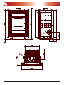
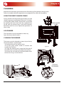
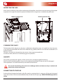
Stufe a Pellet User manual Cleopatra Read the instructions carefully before installation, use and maintenance. The instruction book is an integral part of the product. 2 Congratulations! You are now the owner of an Extraflame stove The Extraflame pellet stove is a great heating solution developed from the most advanced technology with top quality machining and modern design, aimed at making you enjoy the fantastic sensation that the heat of a flame gives, in complete safety. This manual will help you to use your stove correctly. It must be read with great attention before use. IMPORTANT Make sure that your dealer fills the space in that is dedicated to your authorised specialist. He will help you with pleasure if you should have problems using your new pellet stove. AUTHORISED SPECIALIST COMPANY _________________________________________________________________ Mr. _______________________________________________________________________ STREET NAME __________________________________________N°. __________________ Post code _______ TOWN/CITY _________________ COUNTY ______________________ TELEPHONE _________________________ FAX __________________________________ Cleopatra has been realised according to the Directive: 89/106 EEC (Construction Products) and the Standard: EN 13240 3 Index Chapter 1 WARNINGS AND SAFETY DEVICES ......................................................................................................................................5 Chapter 2 TECHNICAL FEATURES ..........................................................................................................................................................6 Chapter 3 WHAT IS THE PELLET? ............................................................................................................................................................8 PELLET STORAGE ........................................................................................................................................................................................................8 PELLET FEEDING .........................................................................................................................................................................................................9 Chapter 4 ASSEMBLY AND INSTALLATION INSTRUCTIONS..............................................................................................................11 GLOSSARY .................................................................................................................................................................................................................. 11 INSTALLATION .......................................................................................................................................................................................................... 12 ACCEPTED INSTALLATIONS ........................................................................................................................................................................ 12 UNACCEPTED INSTALLATIONS .................................................................................................................................................................. 12 CONNECTION OF THE SMOKE CHANNEL OR FITTINGS TO THE FLUE................................................................................................ 13 GAS EXHAUST SYSTEM ................................................................................................................................................................................. 13 CHIMNEY OR INDIVIDUAL FLUE ................................................................................................................................................................ 14 APPLIANCE CONNECTION TO THE FLUE AND EXHAUST OF THE COMBUSTION PRODUCTS .......................................... 15 CHIMNEY CAP................................................................................................................................................................................................... 15 CONNECTION TO EXTERNAL AIR INLETS ....................................................................................................................................................... 16 INSULATION, FINISHINGS, COVERINGS AND SAFETY RECOMMENDATIONS ................................................................................. 16 NATIONAL, REGIONAL, PROVINCIAL AND MUNICIPAL REGULATIONS ............................................................................................. 16 Chapter 5 USE17 BASIC INSTRUCTIONS............................................................................................................................................................................................ 17 AIR REGISTER............................................................................................................................................................................................................. 17 IGNITION ..................................................................................................................................................................................................................... 17 NORMAL FUNCTIONING ...................................................................................................................................................................................... 18 SWITCH-OFF .............................................................................................................................................................................................................. 18 Chapter 6 CLEANING .............................................................................................................................................................................19 USING THE GRATE SHAKER COMBS ................................................................................................................................................................. 19 ASH DRAWER ............................................................................................................................................................................................................ 19 CLEANING THE BURNER ....................................................................................................................................................................................... 19 INSPECTING THE LIDS ........................................................................................................................................................................................... 20 CLEANING THE GLASS ........................................................................................................................................................................................... 20 GASKETS ..................................................................................................................................................................................................................... 20 CONNECTION TO THE FLUE................................................................................................................................................................................. 20 Chapter 7 RECOMMENDATIONS FOR USE...........................................................................................................................................21 Chapter 8 WARRANTY ...........................................................................................................................................................................23 Chapter 9 QUALITY CONTROL ..............................................................................................................................................................25 4 Chapter 1 WARNINGS AND SAFETY DEVICES The stoves produced in our establishment are built For safety reasons, remember that: paying attention to the individual components in a way to protect the user and the installer from any The stove must not be used by children or accidents. unassisted disabled persons. Installation must be carried out by authorised personnel who must provide the buyer with a system declaration of conformity certificate and will assume full responsibility for final installation and as a consequence the correct functioning of the installed product. It is necessary to bear in mind all laws and national, regional, provincial and town council Standards present in the country the appliance has been installed. Extraflame S.p.A. cannot be held responsible for the failure to comply with such precautions. The instruction manual is an integral part of the product: make sure that it always accompanies the appliance, even if transferred to other owners or user or is transferred to another place. If it is damaged or lost, request another copy from the area technician. This stove must be destined for the use for which it has been expressly realised. The manufacturer is exempt from any liability, contractual and extracontractual, for injury/damage caused to persons/animals and objects, due to installation, adjustment and maintenance errors and improper use. After the packaging has been removed, check the integrity and completeness of the contents. If this does not comply, contact the dealer where the appliance was purchased. All components that make up the stove must be replaced with original spare parts exclusively by an authorised after-sales centre, thus guaranteeing correct functioning. The safety and adjustment devices must not be modified without the authorisation or indications of the manufacturer. Do not close or reduce the dimensions of the airing vents in the place of installation. The airing vents are indispensable for correct combustion. Do not leave the packaging elements within reach of children or unassisted disabled persons. The hearth door must always be closed during normal functioning of the product. Avoid direct contact with parts of the appliance that tend to heat up during functioning. Check for the presence of any obstructions before switching the appliance on following a prolonged standstill period. If the flue should catch fire, be equipped with suitable systems for suffocating the flames or request help from the fire service. MAJOLICAS: the company has chosen majolica tiles, which are the result of high-quality artisan work and therefore the majolica may present crackles, speckles, and shadings. These characteristics certify their precious origin.Enamel and majolica, due to their different coefficient of dilatation, produce microcrackles, which show their authentic feature.For the cleaning of the majolica we suggest you use a soft and dry cloth; if you use a detergent or liquid, the latter might soak in and make the crackles more visible. The stove must be serviced at least once a year, programming it in advance with the technical aftersales service. WARNINGS AND SAFETY DEVICES 5 Chapter 2 TECHNICAL FEATURES Features Weight Height Width Depth Flue exhaust pipe diameter Air intake pipe diameter Max. heating volume Max. global heat output Max. useful heat output - useful output power to the air - useful output power to the water Min. useful heat output - useful output power to the air - useful output power to the water Min. hourly fuel consumption Max. hourly fuel consumption Feed-box capacity Recommended flue draught Minimum flue draught Maximum flue draught U.M. Cleopatra kg mm mm mm mm mm m3 kW kW kW kW kW kW kW kg/h kg/h kg Pa Pa Pa 160 1165 750 599 150 150 115 10.0 8.0 8.0 4.0 4.0 ~ 1.0 ~ 2.0 ~ 15 ~ 17 14 20 Tests performed using wooden pellets as fuel with calorific value of 4.9 kW/h/kg. The data given above is indicative and not binding. The manufacturer reserves the right to make any modifications in order to improve product performance. 6 TECHNICAL FEATURES Chapter 2 figure 2.1 TECHNICAL FEATURES 7 Chapter 3 WHAT IS THE PELLET? Pellets are realised by subjecting wood shavings i.e. the rejects of pure wood (without paint) sawmill, carpenter products and products from other activities connected to working and transforming wood, to very high pressures. This type of fuel is absolutely ecological as no glues are used to hold it together. In fact, the compactness of the pellets is guaranteed through time by a natural substance that is found in wood: lignite. As well as being an ecological fuel, as wood residues are made the most of, the pellet also has technical advantages. While wood has a calorific value of 4.4 kW/kg (with 15% humidity, therefore after about 18 months seasoning), that of the pellet is 5.3 kW/kg. Pellet density is about 650 kg/m3 and water content is equal to 8% of its weight. For this reason the pellet does not have to be seasoned in order to obtain a sufficiently adequate heat yield. The pellet used must comply with the features described by the Standard: Ö-Norm M 7135 DIN plus 51731 UNI CEN/TS 14961 Extraflame recommends the use of pellets with a diameter of 6mm with its products. WARNINGS!!! THE USE OF EXPIRED PELLETS OR ANY OTHER MATERIAL DAMAGES THE FUNCTIONS OF YOUR STOVE AND CAN DETERMINE THE INVALIDITY OF THE WARRANTY AND THE ANNEXED RESPONSIBILITY OF THE MANUFACTURER. PELLET STORAGE To guarantee combustion without problems, the pellets must be kept in a dry place. 8 WHAT IS THE PELLET? Chapter 3 PELLET FEEDING 1. Initially open the lateral door to access the mechanics that allow to feed the pellets and check the correct positioning of lever A. 2. Open the handle of the tank lid. Start position of the lever 2 A 1 figure 3.1 figure 3.2 figure 3.3 3. On opening the tank lid, there is a compartment with a capacity equal to about 5 kg, where the pellets must be inserted. figure 3.4 WHAT IS THE PELLET? figure 3.5 9 Chapter 3 4. At this point close the tank lid, also closing the handle to guarantee sealing. 5. Press point B slightly to allow movement of knob A in the direction indicated by the arrow: in this way the pellets in the compartment will descend into the tank. 2 A 1 ATTENTION!!! With the knob moved towards the front of the stove it is impossible to open the tank lid. figure 3.6 B figure 3.7 6. Once the pellet has descended, take the knob A to its original position (position 2). To fill the tank to maximum capacity just repeat the points from number 1 to number 5 three times (the tank has a total capacity of about 15 kg). The pellet feeding operations can be performed with the stove on or off. ATTENTION!!! Once the feeding procedure has ended, the stove must be as in the original state, i.e. with the side door and the tank lid closed using the handle. 10 WHAT IS THE PELLET? Chapter 4 ASSEMBLY AND INSTALLATION INSTRUCTIONS The installation must be in compliance with: UNI 10683 (2005) heat generators fed with wood and other solid fuels: installation. The chimneys have to be in compliance with: UNI 9731 (1990) chimneys: classification based on thermal resistance. EN 13384-1 (2006) chimneys thermal and fluid-dynamics calculation method. UNI 7129 point 4.3.3 Fire Department dispositions, local rules and prescriptions. UNI 1443 (2005) chimneys: general requisites. UNI 1457 (2004) chimneys: terracotta and ceramic inside pipes. GLOSSARY CLOSED HEARTH APPLIANCE Heat generator which opening is only allowed through the loading of the fuel during use. BIOMASS Biological material, excluding the material incorporated in geological formation and transformed in fossil. BIOFUEL Fuel produced directly or indirectly by biomass. CHIMNEY Vertical pipe with the aim to collect and expel, at a convenient height from the ground, the fuel products coming from only one appliance. SMOKE CHANNEL OR CONNECTION Pipe or connecting element between heat generator appliance and chimney to evacuate fuel products. INSULATION Together of devices and materials used to prevent the transmission of heat through a wall which separates rooms with different temperature. CHIMNEY CAP Device positioned at chimney peak to ease the dispersion of fuel products in the atmosphere. CONDENSATION Liquid products which form when the fuel gas temperature is lower or equal to the water dew point. HEAT GENERATORS Appliance which allows to produce thermal energy (heat) through the rapid transformation, through combustion, of the chemical energy of the same fuel. GATE VALVE Mechanism to modify the fuel gas dynamic resistance. ASSEMBLY AND INSTALLATION INSTRUCTIONS 11 Chapter 4 SMOKE EVACUATION SYSTEMS Flue gas exhaust system independent from the appliance constituted by a fitting or smoke channel, chimney or individual flue and chimney cap. NATURAL DRAUGHT Draught which determinates in a chimney/flue for effect of the volume mass difference existing between smoke (hot) and surrounding atmosphere air, without any mechanical intake aid installed inside it or at its peak. RADIATION AREA Area immediately near the furnace in which the heat caused by combustion is diffused, where there must be no fuelling materials. REFLUX AREA Area where leaking of the fuel products is verified, from the appliance towards the installation room. INSTALLATION The installation must be preceded by checking the chimneys, flues or unload terminals positioning of appliances similarly to: No installation Legal distances Limitations disposed by local administrative regulations or particular authority prescriptions. Conventional limitations deriving from apartment building, constraints or contracts. ACCEPTED INSTALLATIONS Only appliances working softly respect to the room or which do not place the room in depression respect to the external environment, can exist or be installed in the room where the heat generator will be installed. Only in rooms for kitchen use are appliances for cooking food and relative hoods without extractor. UNACCEPTED INSTALLATIONS In the room where the heat generator will be installed the following must not pre-exist or be installed: hoods with or without extractor collective type ventilation pipes. Should these appliances be in rooms adjacent, communicating with the installation room, the simultaneous use of the heat generator is forbidden, where a risk exists of one of the two rooms being placed in depression respect to the other. 12 ASSEMBLY AND INSTALLATION INSTRUCTIONS Chapter 4 CONNECTION OF THE SMOKE CHANNEL OR FITTINGS TO THE FLUE GAS EXHAUST SYSTEM To mount the smoke channels, non-flammable elements will have to be used, ideal for resisting fuel products and their eventual condensing. The use of flexible metal and asbestos cement pipes to connect the appliances to the flue is forbidden, even for pre-existing smoke channels. There must be continuity between the smoke channel and the flue so that the flue does not lean on the generator. The smoke channels must not cross rooms where the installation of the combustion appliances is not allowed. The mounting of the smoke channels must be carried out in order to guarantee smoke seal for the appliance functioning conditions, limit the forming of condensate and avoid it being transported towards the appliance. The mounting of horizontal routes must be avoided. For appliances where ceiling or wall non coaxial discharges respect to the appliance smoke outlet have to be reached, the direction changes will have to realised using open elbows not higher than 45° (see figure below). Insulating product Flue Inspection figure 4.1 figure 4.2 In any case, the smoke channels must seal the fuel and condensing products and be insulated if they pass externally to the installation room. The use of counterslope elements is forbidden. The smoke channel must allow the recovery of soot or be brushed. The smoke channel must be at constant section. Any section changes are only allowed at the flue coupling. It is forbidden to have other air supply channels and pipes for plant engineering, especially if over-sized, transit inside the smoke channels. The mounting of manual draught adjustment devices on forced draught appliances is forbidden. ASSEMBLY AND INSTALLATION INSTRUCTIONS 13 Chapter 4 CHIMNEY OR INDIVIDUAL FLUE The chimney or individual flue must respond to the following requisites: sealed from combustion products, impermeable and suitably isolated and insulated; to the similar conditions of use; be realised with materials which resist the normal mechanical stresses, heat, action of the fuel products and any condensing; have mainly vertical progress with deviations from the axis not higher than 45°; be adequately distanced from fuel or flammable materials through air space or opportune insulation; 20 cm Minimum 80 cm2 C B A Floor-protection figure 4.3 figure 4.4 REFERENCES A B C Inflammable Non-inflammable objects objects 200 100 1500 750 200 100 the appliance must be installed on a floor that has suitable load capacity. If the existing construction does not satisfy this requisite, use the appropriate measures (e.g. load distribution plate). The appliance must be positioned perfectly horizontally. have preferably circular internal section: the square or rectangular sections must have round corners with a radius not lower than 20 mm. have constant internal section, free and independent. have rectangular section with max. ratio between the sides of 1.5. It is recommended that the smoke pipe be equipped with a collection chamber for solid materials and any condensing situated under the smoke channel inlet, so that it can be easily opened and inspected from airtight door. 14 ASSEMBLY AND INSTALLATION INSTRUCTIONS Chapter 4 APPLIANCE CONNECTION TO THE FLUE AND EXHAUST OF THE COMBUSTION PRODUCTS The flue must receive the discharge from only one heat generator. The direct discharge towards closed spaces is forbidden, even with clear sky. The direct discharge of the fuel products must be at roof and the smoke pipe must have the features provided in the “Chimney or individual flue” section. CHIMNEY CAP The chimney cap must comply with the following requisites: have an internal section equivalent to that of the chimney; have useful outlet section not lower than double the chimney internal section; be built in order to avoid rain, snow, foreign bodies penetrating the chimney and in order that, in case of winds in any direction and inclination, the discharge of the fuel products is assured. be positioned in a way to guarantee an adequate dispersion and dilution of the fuel products and, however, outside the reflux area in which the formation of counterpressures occurs. Such area has different dimensions and configuration depending on the covering inclination angle, it is therefore necessary to adopt the minimum heights indicated in the figure layouts below. The chimney cap must not have mechanical intake means. FLAT ROOF 50 cm 50 >5m <5m <5m figure 4.5 SLOPING ROOF Distance > A Distance < A 50 cm over the ridge REFLUX AREA reflux area height H min β figure 4.6 ASSEMBLY AND INSTALLATION INSTRUCTIONS 15 Chapter 4 CHIMNEY CAPS, DISTANCES AND POSITIONING Distance between the Minimum chimney height Roof inclination ridge and the chimney (measured from outlet) β A (m) H (m) < 1,85 0,50 m above the ridge 15° > 1,85 1,00 m of the roof < 1,50 0,50 m above the ridge 30° > 1,50 1,30 m of the roof < 1,30 0,50 m above the ridge 45° > 1,30 2,00 m of the roof < 1,20 0,50 m above the ridge 60° > 1,20 2,60 m of the roof CONNECTION TO EXTERNAL AIR INLETS The appliance must be able to use the necessary air to guarantee regular functioning through external air inlet. The air inlets must comply with the following requisites: 1. have a total free section of at least 80 cm2. 2. must be protected by grates, metal net or suitable protections as long as they do not reduce the minimum section stated in point 1 and positioned in order to avoid them being obstructed. The air flow can also be obtained from an adjacent room to the installation one, as long as the flow can happen freely through permanent openings communicating with the outside. The adjacent room, respect to the installation one, must not be put in depression respect to the external environment by means of reverse draught caused by the presence of another used appliance or intake device in such room. The permanent openings in the adjacent room must comply with the above-described requisites. The adjacent room cannot be set up as garage, storage for fuelling material or activity with danger of fire. INSULATION, FINISHINGS, COVERINGS AND SAFETY RECOMMENDATIONS The coverings, independently from the materials with which they are made, must constitute a selfsupporting construction respect to the heating block and not be in contact with it. The wooden or fuelling materials beam and finishings must be positioned outside the hearth radiation area or adequately insulated. In case coverings in fuelling material or sensible to heat exist in the space above the generator, an insulating and non fuelling protection diaphragm must be inserted. Elements in fuelling or inflammable material like wooden furniture, curtains, etc., directly exposed to the hearth radiation, must be positioned at a safe distance. The appliance installation must guarantee easy access for cleaning the same appliance, discharge gas pipe and flue. NATIONAL, REGIONAL, PROVINCIAL AND MUNICIPAL REGULATIONS It is necessary to bear in mind all laws and national, regional, provincial and town council Standards present in the country the appliance has been installed. 16 ASSEMBLY AND INSTALLATION INSTRUCTIONS Chapter 5 USE BASIC INSTRUCTIONS The stove you have purchased uses pellet fuel. This type of material is obtained from natural waste from the machining of wood. By means of a special process that does not require the use of any binding agent and additive, the waste is compressed in industrial machinery under high pressure and they become solid wooden pellets. IT IS PROHIBITED to burn non-pelletised raw materials inside our stoves. The failure to comply with these prescriptions voids all guarantees and could jeopardise the safety of the appliance. The following recommendations must be followed the first two or three times the stove is ignited: It is possible that slight odours are produced due to the drying of the paints and silicones used. Do not remain in the environment for long periods. Do not touch the surfaces as they could still be unstable. Air the room well several times. The hardening of the surfaces is terminated after several heating processes. This appliance must not be used to burn waste. AIR REGISTER The Cleopatra stove has a register for the regulation of primary air for combustion: the regulation knob is accessible on the left of the ash drawer by opening the lower door. The register allows to regulate the inlet air used for combustion of the pellet that determines consumption and the consequent heat output supplied (e.g. the maximum consumption of fuel and the maximum power developed correspond to complete opening of the valve). IGNITION Before switching the stove on the following points must be verified: the feed-box must be full of pellets the combustion chamber must be clean The brazier must be completely free and clean the lever that allows interruption of the pellet supply must be completely open The ignition procedure is manual and envisions the following points: Check that the register of the primary air is completely open Position a pair of firelighters between the pellets in the burner light the firelighters close the glass door ON OFF figure 5.1 USE 17 Chapter 5 ATTENTION!!! 1. DO NOT USE ANY INFLAMMABLE LIQUIDS FOR IGNITION 2. DO NOT ALLOW THE BAG OF PELLETS TO COME INTO CONTACT WITH THE BOILING HOT STOVE DURING THE FILLING PHASE NORMAL FUNCTIONING When ignition has taken place, the user can adjust the heating power through the primary air register from the minimum power (register partially closed) to the maximum power (register completely open). ATTENTION!!! 1. The lid of the pellet container must always be closed. It must only be opened during the fuel loading phase. 2. The bags of pellets must be kept at least 1.5 metres from the stove. 3. It is recommended that the feed-box is always half full. SWITCH-OFF Cleopatra is supplied with a system that interrupts pellet supply to the burner: using a lever it is possible to block the natural sliding of the pellet towards the burner. In this way it is possible to “switch the stove off ”, which will continue its functioning once the pellets have finished, which is under the blocking lever. With the lever in the “ON” position the stove works regularly making the pellets slide towards the burner. With the lever in the “OFF” position the pellets will no longer be supplied to the burner. The stove will continue to burn until the pellets present are completely finished in the burner. To switch the stove back on, turn the lever to the “ON” position, place the 2 firelighters between the pellets in the boiler and ignite the flame manually. ON OFF figure 5.2 18 USE Chapter 6 CLEANING Maintenance operations guarantee correct functioning of the product through time. Failure to comply with these operations can jeopardise the safety of the product. USING THE GRATE SHAKER COMBS During normal stove functioning the cinders must be shaken to prevent stratification of the ash. To do this use the grate shaker combs, whose lever is accessible by opening the lower box: hook the supplied irons to the lever to prevent burns and move forwardbackwards and vice versa. Repeat the operation 2-3 times a day. GRATE SHAKER COMBS ASH DRAWER The ash drawer must be emptied on necessity. Open the lower door for access. CLEANING THE BURNER The burner must be cleaned on necessity and every time the product is ignited again. Remove the cast iron burner cover Use the grate shaker combs to remove and combustion residues. Using the cleaning rod, scrape the final part of the pellet tank to remove any deposited residues. remove the ash and the unburned pellets from the burner using a suction device. figure 6.1 2 1 3 CLEANING THE BURNER ASH DRAWER figure 6.2 CLEANING figure 6.3 19 Chapter 6 INSPECTING THE LIDS If the stove has difficulty with perfect combustion of the pellets, check the correct positioning of the upper inspection lid or open the lateral inspection lid (fixed with 4 winged nuts) and clean the pellet tank. Upper inspection lid Lateral inspection lid figure 6.4 figure 6.5 CLEANING THE GLASS The formation of dirt deposits on the glass is effectively reduced by means of a specific air inlet. However, it can never be prevented with the use of solid fuels (e.g. pellets) and this must not be considered as an appliance defect. The glass must only be cleaned when the stove is clean to prevent explosion. Do not use cloths, abrasive or chemically aggressive products. GASKETS The gaskets guarantee the tightness of the stove and its consequent good functioning. These must be checked regularly: they must be replaced immediately if they are worn or damaged. These operations must be carried out by an authorised technician. For correct functioning, the stove must undergo routine maintenance by an authorised technician, at least once a year. CONNECTION TO THE FLUE Suck and clean the pipe that leads to the flue yearly or anytime that it is necessary. If there are horizontal tracts the residues must be removed before they can obstruct flue passage. NON-CLEANING jeopardises safety. 20 CLEANING Chapter 7 RECOMMENDATIONS FOR USE Problem Possible cause The flames go out Butterfly valve in the closed flue Flue gas exhaust pipe blocked by soot Flue draught too low Insufficient primary air inlet Burner dirty and blocked Gaskets used Upper inspection lid positioned incorrectly The pellets do not slide into the tank Smoke escaping from the opening of the pellet tank lid Gaskets used Butterfly valve in the closed flue Flue gas exhaust pipe blocked by soot Flue draught too low Burner dirty and blocked Upper inspection lid positioned incorrectly The walls inside the stove become excessively dirty during functioning Butterfly valve in the closed flue Flue gas exhaust pipe blocked by soot Flue draught too low Insufficient primary air inlet Burner dirty and blocked Gaskets used Upper inspection lid positioned incorrectly RECOMMENDATIONS FOR USE Possible solution Check that the flue is not obstructed by soot, that the butterfly for draught regulation is not completely closed and that draught between 14 and 20 Pa is guaranteed Increase the inlet primary air using the regulation knob Use the grate shaker combs to clean the burner Check the correct position of the upper inspection lid Check sealing of the upper lid gaskets, of the intermediate base of the tank, the lateral inspection lid and the upper inspection lid. If they are worn, contact qualified staff for their replacement Check the opening of the lever that blocks sliding of the pallet into the tank Check sealing of the upper lid gaskets, of the intermediate base of the tank, the lateral inspection lid and the upper inspection lid. If they are worn, contact qualified staff for their replacement Check that the flue is not obstructed by soot, that the butterfly for draught regulation is not completely closed and that draught between 14 and 20 Pa is guaranteed Increase the inlet primary air using the regulation knob Use the grate shaker combs to clean the burner Check the correct position of the upper inspection lid Check that the flue is not obstructed by soot, that the butterfly for draught regulation is not completely closed and that draught between 14 and 20 Pa is guaranteed Increase the inlet primary air using the regulation knob Use the grate shaker combs to clean the burner Check the correct position of the upper inspection lid Check sealing of the upper lid gaskets, of the intermediate base of the tank, the lateral inspection lid and the upper inspection lid. If they are worn, contact qualified staff for their replacement 21 Chapter 7 The fire burns well but the stove and the room do not heat up Excessive flue draught Room of installation too big or with dispersion points of excessive heat. The pellet burns too quickly Excessive flue draught Excessive inlet primary air Smoke escaping in the room during normal functioning Butterfly valve in the closed flue Flue gas exhaust pipe blocked by soot Flue draught too low Burner dirty and blocked Gaskets used Upper inspection lid positioned incorrectly The flue becomes wet and covered with soot with condensate escaping from the pipes The flue is too cold The transversal section of the flue is excessive Butterfly valve in the closed flue Flue draught too low Burner dirty and blocked Gaskets used Upper inspection lid positioned incorrectly The flame only burns slightly even if the primary air valve is open Butterfly valve in the closed flue Flue gas exhaust pipe blocked by soot Flue draught too low Insufficient primary air inlet Burner dirty and blocked Gaskets used Upper inspection lid positioned incorrectly The pellets do not slide into the tank 22 Regulate draught to between 14 and 20 Pa using the butterfly in the flue Insulate the room as well as possible in order to limit heat dispersion Regulate draught to between 14 and 20 Pa using the butterfly in the flue Reduce the inlet primary air using the regulation knob Check that the flue is not obstructed by soot, that the butterfly for draught regulation is not completely closed and that draught between 14 and 20 Pa is guaranteed Increase the inlet primary air using the regulation knob Use the grate shaker combs to clean the burner Check the correct position of the upper inspection lid Check sealing of the upper lid gaskets, of the intermediate base of the tank, the lateral inspection lid and the upper inspection lid. If they are worn, contact qualified staff for their replacement Al piping must be isolated Reduce flue section Check that the flue is not obstructed by soot, that the butterfly for draught regulation is not completely closed and that draught between 14 and 20 Pa is guaranteed Use the grate shaker combs to clean the burner Check the correct position of the upper inspection lid Check sealing of the upper lid gaskets, of the intermediate base of the tank, the lateral inspection lid and the upper inspection lid. If they are worn, contact qualified staff for their replacement Check that the flue is not obstructed by soot, that the butterfly for draught regulation is not completely closed and that draught between 14 and 20 Pa is guaranteed. Increase the inlet primary air using the regulation knob Use the grate shaker combs to clean the burner Check the correct position of the upper inspection lid Check sealing of the upper lid gaskets, of the intermediate base of the tank, the lateral inspection lid and the upper inspection lid. If they are worn, contact qualified staff for their replacement Check the opening of the lever that blocks sliding of the pallet into the tank RECOMMENDATIONS FOR USE Chapter 8 WARRANTY EXTRAFLAME S.p.A. You are reminded that the manufacturer is the owner of the rights envisioned by the Legislative Decree dated 2 February 2002, n. 24 and the following warranty does jeopardise these rights. This warranty certificate, granted by Extraflame S.p.A., with offices in Montecchio Precalcino (VI), via dell’Artigianato 10, refers to all stove components supplied by Extraflame S.p.A. and is extended to the free repair or replacement of any part of the defective appliance, on the condition that: the same defect is detected within 2 YEARS from the product delivery date and is communicated to an Extraflame S.p.A. After-Sales Centre within 2 months from its discovery; is recognised as such by an Extraflame S.p.A. After-Sales Centre. No cost or expense will be charged to the client for interventions that the Extraflame S.p.A. After-Sales Centre will carry out if provided by the warranty certificate. WARRANTY CONDITIONS The warranty is considered valid on the condition that: 1. The stove is installed in compliance with the Standards in force on this subject, the prescriptions contained in this manual and professionally qualified staff. 2. The customer has filled-in and signed the warranty certificate, validated by the Extraflame S.p.A. Technical After-sales Service or the dealer. 3. The warrant document, filled-in and accompanied by the receipt, must be kept and shown to staff of the Extraflame S.p.A. Technical After-sales Service in the case of intervention. The warranty is not considered valid in the following cases: 1. The warranty conditions described above have not been respected. 2. Installation has not been performed with respect to the Standards in force regarding the provisions described in this manual. 3. Negligence of the customer due to lack of or incorrect maintenance of the product. 4. Damages deriving from atmospheric agents, chemicals, electro-chemicals, improper use of the product, modifications or tampering of the product, inefficacy and/or unsuitability of the flue and/or other causes not deriving from the manufacture of the product. 5. Damage caused by normal corrosion or deposits typical of the central heating systems (condition valid for water products). 6. Improper or negligent use of the stove. 7. All damage caused by transport. It is therefore recommended to carefully check the goods on receipt, informing the dealer of any damage immediately, making a note on the transport document and on the carrier’s copy. Extraflame S.p.A. is not liable for any damage/injury that can, directly or indirectly, affect persons, objects and pets as a consequence of failure to comply with the prescriptions indicated in this manual and the standards in force regarding installation and maintenance of the appliance. WARRANTY 23 Chapter 8 The following are excluded from the warranty: The gaskets, all ceramic or toughened glass, coverings and cast iron or Ironker grids, the painted, chrome or gold -plated details, the majolica, the handles and the electric cables. Colour variations, crackles and slight size differences f the majolica parts are not a reason for claims, as they are natural features of the materials themselves. Masonry work. The warranty also excludes any calibration or regulation interventions of the product in relation to the type of fuel or the type of installation. Further clauses If during normal use of the product defective or badly working particulars should be detected, the replacement of such particulars will be free of charge, ex dealer who made the sale or ex our area AfterSales Centre. For products sold abroad, the same situations will always be free of charge, ex our establishment, with the exception of particular conditions agreed during negotiations with the foreign distributor. In case of replacing particulars, the warranty is not extended. No compensation will be paid for the time the product is inefficient. This is the only valid warranty and no one is authorised to issue others in name or on behalf of EXTRAFLAME S.p.A.. Recommended inspection (with payment) Extraflame recommends that the functional inspection of the product is performed by an Extraflame authorised Technical After-Sales Centre, which will supply all information for correct use. WARRANTY INTERVENTION The request for information must be sent to the dealer. LIABILITY EXTRAFLAME S.p.A. does not grant any compensation for direct or indirect damages caused or dependant by the product. LAW COURT The Vicenza Law Court is elected as the competent court for any disputes. 24 WARRANTY Chapter 9 Chapter 9 QUALITY CONTROL Document to be kept and produced if an intervention is requested under warranty Name Surname Address Post code Municipality of residence Province Telephone Model Serial N°. Dealer Date of Purchase IMPORTANT: I accept I do not accept Information note for the purpose and effect of Legislative Decree 196/2003 - Your personal data is processed by the company with full respect of the Legislative Decree 196/2003 for the entire duration of the contractual relationship and subsequently, in order to fulfil all legal requirements as well as to efficiently manage the commercial relationships. The data can only be communicated to other external subjects to protect credit and for better management of our rights relative to individual commercial relations, as well as communication to third parties due to specific obligations of the law. The affected body has the faculty to exert the rights recognised in art. 7 of the stated decree QUALITY CONTROL 25 Notes 26 Notes 27 Stufe a Pellet EXTRAFLAME S.p.A. Via Dell’Artigianato, 10 36030 MONTECCHIO PRECALCINO Vicenza - ITALY Tel. 0445/865911 Fax 0445/865912 http://www.lanordica-extraflame.com E-mail: [email protected] This document is available at www.extraflame.it/support Manuale utente Cleopatra REV 003 0810008