1
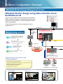
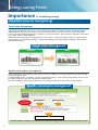
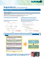
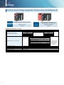
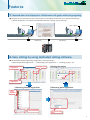
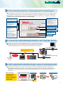
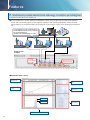
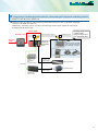
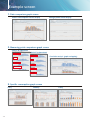
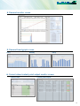
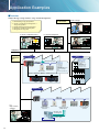
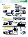
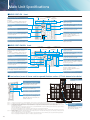
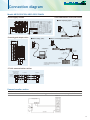
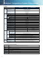
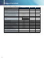
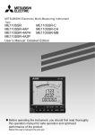
Mitsubishi Electric
Energy-saving Data Collection Server
EcoWebServer #
Simple - Convenient - Compact
Realizing Energy
Visualization and Demand Management
System Configuration Example
Mitsubishi Electric Energy Management System
Mitsubishi Electric Energy-saving Data Collection Server
EcoWebServer Ⅲ
Support factory, building and school energy-saving activities.
Build visualized environments and manage energy effectively.
Support to energy conditions at all times and quickly resolve
energy loss problems.
Finaly reduce energy loss, increase productivity and cut
production costs.
LAN(Ethernet)
Mitsubishi
Electric
web-enabled
air-conditioning
collection
controller
Energy-saving method
EcoWebServer #
(with demand control function)
Comparatively high specific consumption (waste
of energy, negative influence on productivity)
Ex) kWh of electricity per day can be saved
with improvement.
Pulse
signal
• Facilities start-up too fast
• After investigation and deciding appropriate
start-up time, implement countermeasure
Air conditioning
Compare data before and after
implementing countermeasure
( kWh reduced per day)
Demand
control
Implement similar countermeasures
for other facilities
MELSEC programmable
controller
Q Series, QnA Series,
A Series, L Series, F Series*
*F Series requires serial converter
Support energy-saving activities using
“Visible Management”
1. Monitor/Manage energy by department
2. Specific consumption-based management of energy-saving activities
3. Monthly/Annual target-based management
Energy
Energy
Measuring
Measuring
Unit
Unit
(EcoMonitorPro) (EcoMonitorLight)
4. Monitor equipment operating status
5. Manage/Record energy data
Entire factory
Plant manager
Employee A
I see…
2
Oh no!
ion has
Consumpt mpared
co
increased .
ar
to last ye
Employee B
We need to use airconditioning less this month.
CONTENTS
E-mail notification
Transfers files in CSV format
abnormal upper/lower limits,
operating status,
target value over specific
consumption,
over planned energy value,
error information
zoom (1 or 5 min), daily, monthly,
annual, facility (daily),
specific consumption,
demand (daily, monthly, annual),
demand alarm, control,
operation history, system log file
Acquire time information
Adjust
EcoWebServer # clock
FTP server
SMTP server
SNTP server
(File server)
(Mail server)
(Time server)
Receving point
Demand
measurement
Electronic multi-measuring
instrument (ME96SS)
Data collection inside
inner register
●System Configuration Example…… P.2
●Energy-saving Points………………… P.4
●Lineup………………………………… P.6
●Features……………………………… P.7
●Example screen…………………… P.12
●Application Examples……………… P.14
●Main Unit Specifications…………… P.16
●Connection diagram……………… P.17
●Function Comparison/System
Environment………………………… P.18
●External Diagram/Bundled
Products List……………………… P.19
●Support terminal…………………… P.20
●Related Products…………………… P.21
●Safety Precautions………………… P.22
Measurement data
written to inner register
Ethernet
(MELSEC communication protocol)
Collects
production data
Up to 32 units
Network
monitoring
lamp
MITSUBISHI
GOT
QE81WH QE82LG
MELSEC-Q Series
Energy measuring module /
Insulation monitoring module
Check demand information
and alarm records onsite
Specific
consumption
management
Collects energy data
MDU breaker
Electronic multi-measuring
instrument
(ME96SS)
Analog input
Temperature input
Contact output
remote control of load at
(Enables
locations far from EcoWebServer #)
Target-based
management
Air circuit breaker
(AE-SW Series)
Production line
For monitor equipment status
mail
Oh, an e- an alarm
warning of n line A. Alarm
tio
uc
od
in pr
activated
For managing objectives
Did we
achieve
our target
this month?
For improvement activities
We can
reduce
waste even
further here.
3
Energy-saving Points
Importance of visualizing energy
Essentials Issues for Saving Energy
Target Value Management
Managing objectives is a very important issue when practicing energy savings.
“Target value management” is the process of transforming actual conditions into ideal conditions, and thereby requires
understanding the actual situation and how much “unseen” waste there is. For this reason, target value management
involves performing detailed management of operations, moving from months to days and lines to equipment, and evolving
from “seeing” waste to “understanding” it.
Additionally, when using target value management, it is necessary to construct and put into practice an organization that
values “people who set objectives (manage),” “people who find things” and “people capable of thinking of improvements
and implementing them.”
Target Value Management
Monthly
Daily
Specific consumption management
In lines where there is a large difference in production volume, it is difficult to save energy and improve productivity using
energy management alone.
By understanding specific consumption —energy consumed per product— waste in energy and production processes can
be clarified, and it becomes easier to implement countermeasures.
Rather than simply not using energy, it’s important to use energy efficiently when, where and how much needed.
Specific consumption management
EM (Energy loss Minimum) activities
Actual
• No-load power is consumed when there is no production.
• Lights are on in areas where there are no people.
• There are no inverters, so an unnecessary amount of energy is being used.
This is
specific consumption
management
Improvements
Discover waste
Energy required for production:
Ideal
• Necessary
• Necessary
• Necessary
time (year, month, day, hour, minute, second...)
place (all, building, department, production line, equipment)
amount (technical standards, use/operation standards)
Improve productivity ( ➔ Save energy)
The ideal condition is efficient use of the necessary amount of energy, at the necessary place and necessary time.
4
Importance of Demand Monitoring
Energy Saving by visualizing demand
What is “Demand”....?
Demand is average electric power at a specified period. This period for demand differs for each country and the way of
management method.
Electric fee is basically determined based on the highest demand in one year(→contract demand).
The highter the contract demand is, the more expensive the electric basic charge is.
There are two types of basic demand management method as below.
(2) Fixed block demand management method
The demand period consists of only an interval.
(2) Rolling block demand management method
The demand period consists of interval and sub interval.
Interval is the period for caluclation of average electric.
Sub interval is the period for updata the calculation.
Fixed block demand management
Rolling block demand management method
Ex) Interval:30min
Ex) Interval:15min、Sub interval 5min
EcoWebServer# with demand monitoring function comply with the Fixed block
demand management method. Interval can be selected from 15min or 30min.
Subtotal Volume
• Demand (power demand) is computed and calculated by taking
pulses from the multi-measuring meter
(transaction meter) for power demand.
Estimation
• The value at the end of the 30-minute time limit is estimated
from the measured demand (power demand).
Reduce
demand
Warning
• Based on the results of the estimation, an alarm is output and a
notification sent when the objective demand has been exceeded.
• The alarm notification can be a buzzer, display lamp, etc., which
is sent through the contact output.
Reduce
basic free
Load interruption
• Load interruption may be necessary depending on power use.
• A control output signal can be used to automatically interrupt
the load.
Realize visualization of energy and demand
management with one EcoWebServer #.
5
Lineup
Mitsubishi Electric Energy-saving Data Collection Server EcoWebServer Ⅲ
Product name
Energy-saving Data Collection Server
Model no.
MES3-255C-EN
Communication
CC-Link
Network Specifications (CC-Link)
Item
Transmission speed
CC-Link communications section
Maximum total cable length
(maximum transmission distance)
6
Maximum number of connected units
Communication method
Synchronization method
Encoding method
Transmission route format
Transmission format
Error control method
Connecting cable
Product name
Energy-saving Data Collection Server
(with demand control function)
Model no.
MES3-255C-DM-EN
Communication
CC-Link
Specifications
156kbps / 625kbps / 2.5Mbps / 5Mbps / 10Mbps
Transmission speed
Cable length between stations
Maximum total cable length
156kbps
1200m
625kbps
900m
2.5Mbps
20cm or more
400m
5Mbps
160m
10Mbps
100m
64 units 1. Total number of stations
However, conditions
a+b×2+c×3+d×4≦64
on the right must
a: 1 station occupied, b: 2 stations occupied,
be met
c: 3 stations occupied, d :4 stations occupied
2. Number of units connected
* Unregistered station
16×(A+D)+54×B+88×C≦2304
numbers from station
A: Number of remote I/O stations
…64 max
1 to the maximum
B:Number of remote device stations
…42 max
number of stations
C:Number of local stations, intelligent device stations …26 max
are counted as
reserve stations.
D:Number of reserve stations *
Broadcast polling method
Frame synchronization method
NRZI method
Bus (RS-485)
HDLC compatible
CRC (x16+x12+x15)
CC-Link Ver1.10-compatible dedicated cable
Features
1.
Measured data can be displayed on a Web browser with graphs without any programing.
● Using the HTTP Server function, the collected data is transmitted via Ethernet across the Internet/Intranet
so that all employees can confirm and understand amount of energy used in real-time.
Client computer
Person in charge of Building/Site A
Client computer
View via Web browser
LAN
(Ethernet)
Person in charge of Building/Site B
LAN
(Ethernet)
2. Easy setting by using dedicated setting software.
● The minimum required registering configuration on the measuring is
“①Measuring terminal registration”→“②Measuring point registration”→“③Writing project”only.
①Measuring terminal
registration
③Saving project
③Writing the project
②Measuring point
registration
①Measuring terminal registration
②Measuring point registration
Select
using
terminal
Select measuring
point information
Select measuring
items
7
Features
3.
Add new comparison screens according to the scenario. Strong support provided for analyzing activities.
1 Date comparison graph
● The display procedure is select“① Measuring point group/name → ② Graph display date”and select
“③ Display”only.
● A comparison of the specified date and items can be displayed.
①Select the measuring point group/
measuring point name you want
to display
②Select the graph display date
③Select the display and display the screen
2 Measuring point comparison graph
● The display procedure is to select“① Measuring point group/name → ② Graph display format →
③ Graph No. → ④Graph display intervals etc.”and select“⑤ Display”only.
● It’
s possible to select graphs and display various graphs in the format of your choice. It’
s also possible to
display the same graph, making it easy to understand graph correlations.
Selection
screen
③Select the number of the
graph to be displayed.
(When displaying the
same graph in a cascade,
select the same number.)
②Select the graph display format
(Bar graph/Line graph/Stacked bar graph)
④Select the graph
display interval/
date/automatic
update (optional)
Display
screen
①Select the
measuring point group/
measuring point name
you want to display
⑤Select the display button to
display the screen
Analysis by department
General affairs
Analysis by application
Electrical outlet
Sales
Lightning
Designing
Purchasing
Accounting
8
Air conditioning
Office automation
Correlation analysis (graph overlapping)
4.
Easily understand productivity by confirming the specific consumption graph
● By integrating the production volumes from the measuring terminal and PLC, the specific consumption graph
can be easily displayed and points related to the drop in specific consumption can be easily understood.
● Additionally, by comparing two specific consumption graphs at the same line, it is possible to confirm the
benefits at the time the countermeasure was implemented.
Objective value setting
window button
Display date selection menu
● Select
the date of the data
from the pulldown menu.
● Objective
values can be set for each
measuring point from the specific
consumption screen.
● A password is required to change
objective value settings.
* The password is set so that it can
only be changed by the administrator.
Specific consumption measuring
point selection menu
●
Select the specific consumption
measuring point from the
pulldown menu.
Specific consumption amount (=a÷b)
Automatic update fixed
display box
● Yearly/monthly
1hr cycle
● Daily/zoom
Production amount (b)
graph:
Specific consumption target value
data: 1min cycle
Objective value scale
fixed display box
Cumulative amount of
energy used
● Use
the checkbox to select
whether or not to display the
vertical scale of the graph with
the specific consumption
objective value in the center.
Energy used (a)
5. Connection with Mitsubishi Electric GOT display device.
● Information collected on the EcoWebServer Ⅲ can be displayed on the GOT.
● By displaying the alarm state/measuring value for energy information/demand,
real-time monitoring at the site and urgent countermeasures are possible.
LAN
(Ethernet)
Displays demand information
and alarm information
Ethernet
(Melsec comunication protocol)
Alarms
displayed
via the LAN
Network monitor
display lights
(PATLITE)
EcoWebServer Ⅲ
equipped with demand monitoring
function
(
MITSUBISHI GOT
)
MITSUBISHI PLC
6. Alarm output/email notification through a variety of monitoring functions.
● Objective values (upper/lower) and error information can be transmitted through email notifications/
alarm output, and changes in status can be recognized immediately. The result of the careful target value
management and monitoring the status monitoring ensure that problems occurring at the site are not
overlooked.
<Items monitored>
・Energy plan value
・Specific consumption
objective value
・Upper/lower irregularity
・Change in operating state
・Error information
・Demand alarm
Alarm output
SMTP Server
Email notification
over the set target value
Alarm
lamps
9
Features
7. Simultaneously visualize demand trends and energy consumption per building/load
Compatible model: MES3-255C-DM-EN only
● As the breakdown of power demand (load balance) can be easily understood from the power demand
trends and stacked bar graphs for each regional substation and operating equipment can be reviewed,
and operations can be planned and proposed based on the analysis results, which enable peak shift/peak
cut.
Load installed in a location separated from
the EcoWebServer Ⅲ can also by controlled
by CC-Link transmission.
(CC-Link: total cable length up to 1.2km)
Person in charge
of Building/Site A
Power receiving facilities
Person in charge
of Building/Site B
Person in charge
of Building/Site C
Graph screen
example
Receiving
electricity
power demand
(line graph)
Selected power volume
(stacked bar display)
●Demand monitor screen
Current demand
display area
Alarm status display
area
Demand load
curve
Demand information
display area
Target Value
Fixed Value
Current day demand trend graph
10
Control status
display area
8.
Energy-saving air conditioning operation realized by interconnecting with integrated air-conditioning controller.
Compatible model: MES3-255C-DM-EN only
● Demand control possible by interconnecting with Mitsubishi Electric Web-compatible integrated
controller̶AE-200E, AG-150A, etc.
Additionally, automatic control of load possible through contact point output via main unit of
EcoWebServer Ⅲ and CC-LINK.
Pulse output
Demand level signal
Demand power
Receving
point
EcoWebServer Ⅲ
equipped with
demand monitor
function
LAN
(Ethernet)
Capacity-saving control
combined with
energy-saving monitor
level (60/70/80/90%)
Mitsubishi Electric AE-200E
Web-compatible integrated
air-conditioning controller
Multi-unit air conditioner
CC-Link
Energy
Measuring
Unit
(EcoMonitorPro)
Transmission
terminal for
digital output
Contact point
output signal
Contact point
output signal
Lighting equipment
Equipment (Motor)
11
Example screen
1. Date comparison graph screen
Electric consumption/current display
Voltage/power factor display
2. Measuring point comparison graph screen
Analysis by application
Electrical outlet
Analysis by department
General affairs
Lightning
Correlation analysis (graph overlapping)
Sales
Air conditioning
Designing
Office automation
Purchasing
Accounting
3. Specific consumption graph screen
Daily
12
Monthly
Yearly
4. Demand monitor screen
5. Demand trend graph screen
Monthly
Daily
Yearly
6. Current value/contact point output monitor screen
Current value
Contact point output
13
Application Examples
■Factories
Support Energy-saving Activities using “Visible Management”.
In the office…
1. Monitor/Manage energy by department
2. Specific consumption-based management of
energy-saving activities
3. Monthly/Annual target-based management
4. Monitoring of equipment operating status
5. Manage/Record energy data
Plant manager
I see…
To monitor equipment status
For target management
mail
Oh, an e- an alarm
notifying of n line A. Alarm
tio
in produc
Employees
Did we
achieve
the target
this month?
activated
Oh no!
ion has
Consumpt mpared
co
increased .
to last year
LAN(Ethernet)
At
production
site…
Factory No. 1
Office
Measurement data
MDU breaker
Administration
Department
· Air conditioning
· Lighting
· Office automation
equipment
· Electrical outlets
· Water/Gas usage
Production
Department
· Power/Power
consumption
· Power factor
· Consumption of
water/steam/air/gas/other
· Specific consumption
data
· Production quantity, other
EcoMonitorPro
Ethernet communications (MELSEC communications protocol)
PLC
PLC
Factory No. 2
For
improvement
activities
We can
reduce
waste even
further here.
Electronic
multi-measuring
instrument
MDU breaker
Energy
Measurement Unit
(EMU3 Series)
Operating status
(contact signal)
Production quantity
(pulse signal)
Production equipment
14
EcoMonitorPro
MELSEC-Q Series
programmable
controller
■Buildings
Building No. 1
Electronic multi-measuring
instrument
Electronic multi-measuring
instrument
Cubicle
Cubicle
Significantly reduce installation cost by using the existing LAN.
1. Manage/Monitor energy by floor/application
2. Manage data remotely
3. Easy for tenants and other personnel to read
meters
4. Monitor operating status of building facilities
(e.g., elevators, escalators, air conditioners)
5. Record/Manage energy data
22F Air conditioning
I see…
21F Lighting
20F Office automation equipment
We need to use the air
conditioner less this month.
Building No. 2
Wow,
d
there’s no nee
to go to the
building.
Building management
(management company)
Router
s!
Good new
has
20th floor
improved vings.
energy-sa
2F Electrical outlets
FTP server
(database server)
1F
Router
Router
Public line
■Stores
1. Remote management of energy data for small,
spread-out stores
2. Compare data of each store
3. Record/Monitor equipment operating status (e.g., manage
freezer/refrigerator temperatures)
4. Easy for tenants and personnel to read meters
Router
Router
Router
Head office
(Administration Department)
ws!
Good nehas
Store B
ed
ov
pr
im
avings.
energy-s
Router
FTP server
(database server)
Store C
Store B
Store A
Public line
Store D
Shopping center
· Power usage
· Water/Gas usage
· Monitor temperature of
refrigerators/freezers
Router
* When using a public line, a dial-up router is required.
* For use via the Internet, a separate contract with an Internet service provider is required.
■Schools
School Department
School grounds/Athletics field
1. Understand power consumption by facility (e.g.,
gymnasium) and equipment (e.g., transformer)
2. Monitor operating status of equipment distributed across
a wide area
3. Save time and staff needed for meter-reading work
4. Record/Manage energy data
Main building
(Administration Department)
Someone forgot to
turn off the lights
in the gym.
FTP server
(database server)
Gymnasium
Dedicated line
Router
LAN(Ethernet)
15
Main Unit Specifications
■MES3-255C-EN front
CC-Link
communication
Contact
section
output section
Server section
Power-supply
section
7-segment LED display
Displays an error code when an error is
detected.
In addition, in IP address display mode, the
preset IP address is displayed at start-up.
LED display
Display each status.
CC-Link station number setting switch
USB interface
Set CC-Link station number.
Not used.
CC-Link transmission speed setting switch
LAN interface CH1
Set CC-Link transmission speed.
Use connected to a computer network.
Contact output terminal block
LAN interface CH2
Closed when conditions monitoring
function conditions are met.
Connect external equipment such as
buzzers and lamps.
Use when connected to a programmable
controller network.
Power-supply terminal block
Connect power supply. (Note 1)
LED display
CC-Link terminal block
Display each status.
Connect CC-Link communication cable.
■MES3-255C-DM-EN front
Power-supply
section
7-segment LED display
Displays an error code when an error is
detected.
In addition, in IP address display mode, the
preset IP address is displayed at start-up.
CC-Link
Demand monitor
communication
section
section
Contact
Server section
output section
LED display
Display each status.
CC-Link station number setting switch
Set CC-Link station number.
USB interface
CC-Link transmission speed setting switch
Not used.
Set CC-Link transmission speed.
LAN interface CH1
Demand monitor section connection terminal
Use connected to a computer network.
Connect cable to pulse input, alarm
output and control output for demand
monitoring. (Note 2)
LAN interface CH2
Use when connected to a programmable
controller network.
Contact output terminal block
Closed when conditions monitoring
function conditions are met.
Connect external equipment such as
buzzers and lamps.
Power-supply panel
When you open the panel, you will see the
power-supply connection terminal. (Note 1)
LED display
CC-Link terminal block
Display each status.
Connect CC-Link communication cable.
■Front surface (cover of Server section opened)/bottom surface (CC-Link transmission device)
Front surface (cover of Server section opened)
Bottom surface
CompactFlash™
memory card EJECT button
RS-232 interface
Not used.
Push the button and remove the
CompactFlashTM memory card.
MODE/STOP/RUN switch
Normally, used in RUN state.
RESET/SELECT switch
Used when resetting the main unit.
CompactFlash™ memory card
Stores programs for collecting and
displaying data. Data collected is also
saved to it. (Note 3)
(Note 1)
(Note 2)
Connect to AC100−240V(+10%, −15%)50/60Hz(±5%). Do not connect to a power supply other than that specified as this may cause an accident.
A separate power supply is required for the demand monitor section when using. When using the main device, AC100−240V(+10%,
−15%)50/60Hz
power is required for the demand monitor connector terminals V1, V2. It is possible to connect power from the power-supply module.
(Note 3) ・ CompactFlashTM memory cards are used in a constantly attached state. If they are removed while the power is on or the memory card is being accessed,
this product will malfunction.
・ When removing the card from the memory card slot, be sure to place the RESET/SELECT switch in the SELECT position and remove it only after turning off
the power supply and the CF CARD LED has turned off.
・ Do not use the CompactFlashTM memory card with any other product. This could corrupt the internal data.
・ Do not insert a CompactFlashTM memory card other than the one included in the package in this device. If a different card is inserted, the system will not
operate correctly.
(Note 4) Be sure to exchange the battery within three minutes after turning off the power. If more than three minutes passes after the battery is removed, the final
one hour of data may be lost or the clock may initialize.
(Data or configuration settings from more than one hour before will not be initialized). If the clock initializes, please set again after backing up the data.
Refer to the operating manual (hardware edition) for the battery replacement procedure.
16
Battery storage
compartment
Store the battery.
Remove the cover and connect
the connector. (Note 4)
Connection diagram
Model: MES3-255C-EN, MES3-255C-DM-EN
Power-supply section
Server communications section (LAN interface)
■When displaying graphs
ERR+
ERR‒
CH1
FG
Client computer
LG
N
CH2
L
AC100∼240V
* MES3-255C
D-type ground
D-type ground
Connecting point output section
AC100∼240V
LAN cable
(straight or cross)
* MES3-255C-DM
LAN network
onsite
Hub
■When setting (CH1)
Hub
■When connecting the PLC (CH2)
CH1
01234567
89ABCDEF
CH1
CH2
1
3
5
7
9
B
D
F
0
CH2
負荷
負荷
負荷
負荷
負荷
負荷
負荷
負荷
負荷
負荷
負荷
負荷
負荷
負荷
負荷
負荷
2
4
6
8
A
C
E
COM
LAN cable
(straight or cross)
LAN cable
(straight or cross)
Attached CD
(setting window)
Production
equipment,
LAN network
Hub
Hub
LAN cable
(straight)
LAN cable
(straight or cross)
Ethernet/Serial
converter
Computer
100/200VAC
or
24VDC
To PLC
Ethernet port/
Ethernet unit
To PLC
calculator link
unit
Operation of Ethernet/serial converter can be
confirmed using the following product.
Line Eye SI-65
CC-Link communication section
Energy-saving data
collection server
(master station)
Terminating
resistance
(110Ω, 1/2W)
DA
DB
DG
SLD
FG
Local station
Local station
(B)
(B)
(W)
(W)
(Y)
(Y)
CC-Link dedicated
cable
DA
DB
DG
SLD
(B)
(B)
(W)
(W)
(Y)
(Y)
CC-Link dedicated cable
FG
DA
DB
Terminating
resistance
(110Ω, 1/2W)
DG
SLD
FG
Demand monitor section
(1)
Where the transaction meter of the multi-measuring power demand meter is 10,000pulse/kWh
Demand Unit
Electricity Meter
17
Function Comparison/System Environment
Functions
MES3-255C-EN
Product Name
MES3-255C-DM-EN
ー
Demand function
Yes
Number of remote I/O stations≦64、
CC-Link terminal device
Number of remote device stations≦42、
Number of local stations≦26
Connection
device
MC protocol connection (LAN CH2 used)
* device read/write
MITSUBISHI PLC, GOT
CC-Link unit (local) connection
* device read
255 points
Measuring points
32 points (includes 255 measuring points)
Number of operation measuring points
Number of
measuring
points
128 points
Virtual measuring points
64 points
Specific consumption measuring points
32 points
Connection point output
Demand
monitoring
Receiving demand
ー
Receiving electric energy
ー
2 points (fixed) whole day, timeframe 1-10
2 points (fixed) whole day, timeframe 1-10
62-day amount
Zoom (every 1min) data
14-day amount
Zoom (every 5min) data
186-day amount
Daily data (on the hour or every 30min)
60-month amount
Monthly data (specified time (00min) once a day)
5-year amount
Yearly data (specified time (00min) once a month)
186-day amount
Virtual measuring point data (daily)
60-month amount
Virtual measuring point data (monthly)
Data saving
function
* CSV format
5-year amount
Virtual measuring point data (yearly)
186-day amount
Specific consumption measuring point data (daily)
60-month amount
Specific consumption measuring point data (monthly)
5-year amount
Specific consumption measuring point data (yearly)
186-day amount
Equipment data (daily)
64KB×4 files
Operating history data
256KB×8 files
System log
Demand data (daily)
ー
186-day amount
Demand data (monthly(daily maximum))
ー
60-month amount
Demand data (yearly(monthly maximum))
ー
5-year amount
Demand alarm/Control log
ー
128KB×62 files
ー
・ Displays current time limit demand load curve
・ Displays graph of same day demand results
Demand monitor
Real-time
Current value monitor
The current value of the specified measuring points are displayed in the units registered for groups and display lists
Displays differential display mode function/differential values for specified measuring points (time differential: amount used
from previous hour to present time, daily differential/monthly differential: amount used from previous summary time to present)
Displays connecting point output status
Connection point output monitor
Display
function
ー
Demand trend graph
Graph
display
Displays demand trend graph
Displays comparison of multiple measuring point data for specified display intervals/time displayed
Measuring point comparison graph
Displays comparison of specified measuring points for desired date
Daily comparison graph
Displays graph after dividing energy volume by number produced
Specific consumption graph
Displays graph of equipment efficiency, number of defects and equipment energy volume
Equipment graph
Download measuring point data, virtual measuring point data, specific consumption data, equipment data,
Data file
operating history data, system log, demand data *, alarms/control log * (*only for products with demand monitoring functions)
Displays measuring points, connection point output and content of email notifications set for EcoServerⅢ
Equipment values list
Transmits main unit error notifications, periodic notifications, upper/lower limit notifications, operating status notifications,
Monitoring
functions
Email notification function
Connection point output
specific consumption objective value notifications, energy plan value notifications and demand notifications * to the
specified SMTP Server (*only for products with demand monitoring functions)
Outputs connection points for EcoWebServerⅢ connection point output module or combined CC-Link input/output module
Recommended system environment
Item
18
Specification
OS (basic software)
Microsoft Windows XP Professional
(32bit)
SP3, Microsoft Windows Vista Business
(32bit)
SP2
Microsoft Windows 7 Professional
(32bit, 64bit)
SP1, Microsoft Windows 8.1 Pro
(32bit, 64bit)
CPU
Pentium® 1GHz processor or faster, or compatible microprocessor(DOS/V-compatible device)
Memory
1GB or more
Hard-disk
If data accumulated by Eco EcoServer III is saved to a computer, that storage capacity is required.
CD drive
1 group or more (required for installing setup software)
Display resolution
1280×1024 pixels or more
Display colors
65536 colors or more
Input device
Mouse and keyboard
External interface
10BASE-T / 100BASE-TX
Web browser
Internet Explorer® 7, 8
(32bit)
,9
(32bit)
, 10
(32bit)
, 11
(32bit)
Java plug-in
Oracle JavaTM 7 JRE 7
(32bit)
, Oracle JavaTM 6 JRE 6
(32bit)
External Diagram/Bundled Products List
Unit : mm
External dimensions
122.5
114
〈Side surface〉
〈Front surface〉
4.5
122.5
97.5
111.5
104
■MES3-255C-EN
〈Bottom surface〉
122.5
44.0
97.5
104
■MES3-255C-DM-EN
97.5
189
122.5
4.5
〈Bottom surface〉
〈Front view〉
〈Side surface〉
Peripheral installation conditions
■MES3-255C-EN
■MES3-255C-DM-EN
Peripheral installation conditions
Peripheral installation conditions
*1
Shows frame roof or wiring duct, part position
Shows frame roof or wiring duct, part position
30mm or more *2
30mm or more *1
5mm or more
D
N
S
17mm or more
5mm or more
30mm or more
80mm or more
Doors
*1 These are the conditions when considering radiation. At the same time, please
secure enough space to replace the battery in the lower layer of the main unit.
10mm or more
30mm or more
80mm or more
Doors
*1 When height of the wiring duct is 50mm or less. Others are 40mm or more.
*2 When height of the wiring duct is 50mm or less. Others are 40mm or more.
Bundled Products List
Product Name
CC-Link communication product
MES3-255C-EN
MES3-255C-DM-EN
Energy-saving Data Collection Server (main unit)
1
CompactFlashTM memory card (software)
1
Setup software (CD-R)/operating manual collection
1
1
Battery (installed in lower surface of main unit battery section) *1
Frame attachment screw
CC-Link terminal resistance(black: 110Ω/2W) (white: 130Ω1/2W)
IEC rail attachment adapter
4 (M4×12)
4 (M4×14)
Black: 2
White: 2
Small 2
Large 2
IEC rail attachment screw (M5 x 10)
2
IEC rail attachment corner washer
2
IEC rail attachment stop metal clamp
2
Operating manual hardware edition
1
*1 To purchase a replacement battery (model name: Q6BAT), inquire at the dealership where you purchased the main product.
19
Support terminal
MES3-255C-EN、MES3-255C-DM-EN
(CC-Link)
Icon/type name
Station type
Number of occupying stations
Energy measuring unit(1P2W, 1P3W, 3P3W)
EMU4-BD1-MB
Remote device station
1 station occupied
Energy measuring unit(1P2W, 1P3W, 3P3W, 3P4W)
EMU4-HD1-MB
Remote device station
1 station occupied
Energy measuring unit
(Power reception and distribution monitoring(standard product 3 circuits))
EMU2-RD3-C
Remote device station
1 station occupied
Energy measuring unit
(Power reception and distribution monitoring(standard product 5 circuits))
EMU2-RD5-C
Remote device station
1 station occupied
Energy measuring unit
(Power reception and distribution monitoring(standard product 7 circuits))
EMU2-RD7-C
Remote device station
1 station occupied
Energy measuring unit
(Power reception and distribution monitoring(3P4W 2 circuits))
EMU2-RD2-C-4W
Remote device station
1 station occupied
Energy measuring unit
(Power reception and distribution monitoring(3P4W 4 circuits))
EMU2-RD4-C-4W
Remote device station
1 station occupied
EMU3-DP1-C
Remote device station
1 station occupied
Remote device station
1 station occupied
Remote device station
1 station occupied
Product Name
Energy measuring unit
MDU breaker(WS-V)
MDU(WS-V)
NF250-SEV/HEV with MDU
NF400-SEP/HEP with MDU
MDU breaker(WS)
MDU(WS)
NF600-SEP/HEP with MDU
NF800-SEP/HEP with MDU
Low-voltage air circuit breaker(AE-SW with CC-Link interface unit)
20
AE-SW(BIF-CC)
Remote device station
1 station occupied
Electronic multi-measuring instrument
ME96SSR-MB
Remote device station
1 station occupied
Electronic multi-measuring instrument
ME96SSH-MB
Remote device station
1 station occupied
Electronic multi-measuring instrument
ME96NSR
Remote device station
1 station occupied
Electronic multi-measuring instrument with transmission function
ME110SSR-C(H)
Remote device station
1 station occupied
Electronic multi-measuring instrument with transmission function
ME110NSR-C
Remote device station
1 station occupied
Thermocouple temperature input unit
AJ65BT-68TD
Remote device station
4 station occupied
Platinum resistance temperature sensor Pt 100 temperature input unit
AJ65BT-64RD3
Remote device station
4 station occupied
Analog-digital conversion unit
AJ65BT-64AD
Remote device station
2 station occupied
Terminal block type 24 VDC input unit(8 points)
AJ65SBTB1-8D
Remote I/O station
1 station occupied
Terminal block type 24 VDC input unit(16 points)
AJ65SBTB1-16D
Remote I/O station
1 station occupied
Terminal block type 24 VDC input unit(32 points)
AJ65SBTB1-32D
Remote I/O station
1 station occupied
Terminal block type DC input transistor output combined unit
(Input 8 points, Output 8 points)
AJ65SBTB1-16DT
Remote I/O station
1 station occupied
Terminal block type DC input transistor output combined unit
(Input 16 points, Output 16 points)
AJ65SBTB1-32DT
Remote I/O station
1 station occupied
CC-Link master/local unit(Local station)
QJ61BT11N
Intelligent device station
1 station occupied
CC-Link master/local unit(Local station)
LCPU/LJ61BT11
Intelligent device station
1 station occupied
Related Products
EcoMeasureⅢ daily/monthly report specific consumption analysis software
This software supports the specific consumption analysis graph and ledger preparation of daily reports, monthly reports
and annual reports from CSV files collected and output by the Mitsubishi Electric EcoWebServerⅢ Energy-saving Data
Collection Server.
* The supporting product version, EcoMeasureⅢ with demand monitoring function, for EcoMeasure Ⅲ, will be released soon.
●Features
●Product Appearance
(1)
Easily create daily, monthly and annual reports.
・Ledger prepared ledger is saved as an Excel file in user-designated place.
(2)
Easily perform specific consumption management as the index of energy-saving activities.
・Possible to manually input production volume and perform specific consumption
management of energy information from EcoServer III and E-Energy.
・Possible to prepare each specific consumption graph (zoom, daily, weekly and monthly).
(3)
Easily collect data.
・CSV files stored in EcoWebServer III and E-Energy can be downloaded with simple
operations.
●Specifications
Specifications
Item
Model name
Connection
devices
Number of units
Target devices
Number of virtual measurement points
Number of virtual measurement point groups
Ledger creation
Ledger
creation
function
Maximum number of items
Calculation items
Specific consumption display
Number of specific consumption
Specific consumption target value
Specific
consumption
management
function
Graph display
List display
Automatic updating
OS
(basic software)
Required software
CPU
Operation
environment
Memory *2
Hard-disk *2
CD-ROM drive
LAN
USB connector (Type A)
Display resolution
Display color
Number of licenses
( number of computers installed in )
MES3-SW1-PR-FR
8 units maximum (combination of following target devices)
EcoWebServerⅢ(MES3-255C-EN)
Maximum 95 points (Total of 95 points including virtual measurement points for calculating measurement management points and virtual measurement points for input.)
* Four arithmetic operations of up to 64 measurement management points (including constants) can be registered in the virtual measurement points for calculation.
Maximum five groups *Addition/Subtraction calculations for up to 32 virtual measurement points can be registered in the virtual measurement point groups.
Daily report creation, monthly report creation, annual report creation
The daily, monthly and annual reports can have up to 2,250 output items.
Analog (including specific consumption)
Maximum, minimum, average
Pulse
Total, maximum, minimum, average
Demand
Maximum
Daily specific consumption, weekly specific consumption, monthly specific consumption and zoom specific consumption *1
Maximum 100 points
Can set by each specific consumption
Specific consumption, target value, production volume, power used (kWh), accumulated power volume (kWh)
* The specific consumption/target value/production volume units can be set freely.
Auto-scale function
Daily/weekly/ monthly specific consumption
Power volume (kWh), production volume, specific consumption, accumulated power volume (kWh), accumulated production amount, specific consumption target value
Zoom specific consumption
Power volume (kWh), production volume, specific consumption, power use/hour
Daily/weekly/ zoom specific consumption
Contents of display newly updated at designated time once per hour each hour
Monthly specific consumption
Contents of display newly updated at designated time once per day each day
Microsoft
Microsoft
Microsoft
Microsoft
Windows
Windows
Windows
Windows
XP
(32bit)
(SP3) Home Edition/Professional
Vista®(32bit)
(SP2) Home Basic / Home Premium / Business / Enterprise / Ultimate
Server 2003
(32bit)
(SP2) Standard
7
(32bit/64bit)
(SP1) Professional
Microsoft Excel 2003
(SP3)/ 2007
(SP3)/ 2010
(32bit/64bit)
(SP1)
If using Windows XP : Pentium processor of 400MHz or higher or a compatible microprocessor (DOS/V- compatible)
If using Windows Vista® or Windows 7 : As recommended for the operating system
As recommended for the operating system
Software: Approx. 100MB or more
Data: 8GB or more *3
1 drive (for installing software)
10/100/1000BASE-T ×1
1 connector (for connecting hardware key)
800×600 pixels or more
256 colors or more
・ 1 license per 1 client
・ Hardware key attached (UBS) (1 unit)
*1 If virtual measurement points for input or measurement points for E-Energy are included, no zoom specific consumption is displayed.
*2 Note that the required memory and available hard-disk space may vary depending on the system environment.
*3 Shows the capacity required when used with maximum eight subsystems connected.
【Daily Report】
【Monthly Report】
【Annual Report】
21
Safety Precautions
1.Safety Precautions to be Followed at all Times
■Operating Environment/Conditions
Using this product in any of the following environments may cause a malfunction or shorten service life. Do not use in environments where:
● Ambient
● Unit
● Relative
temperature outside the range of 0 - 55°
C
average temperature exceeds 35°
C
humidity outside the range of 5 - 95% or where condensation occurs
● Altitude is higher than 2,000m above sea level
● Presence of excessive dust, corrosive gas, salt-saturated air or oily smoke
● Unit
● Daily
is subject to excessive vibration or physical shock
is exposed to rain or drops of water
is exposed to direct sunlight
● Pieces of metal or inductive substances nearby
● Presence of strong electromagnetic field or excessive external electrical noise interference
● Unit
■Installation/Mounting
Be sure to read the user’
s manual before installing/mounting the product.
CAUTION
●For safety, unit installation and all wiring connections should be performed by a qualified electrician.
●Be careful of sharp, metal edges; they may cause injury.
●When tightening screws or connecting wiring, be sure that small particles or cut pieces of electrical wiring do not get inside the unit.
●Check the wiring diagram carefully before making connections. Incorrect connections may cause a malfunction, fire or electrical shock.
●Do not perform wiring work using live circuits. Doing so may cause a malfunction, fire or electrical shock.
●Use electrical wires of appropriate size. Not doing so may cause a fire due to the possible generation of heat.
●Use a solderless terminal that matches the size of the electrical wire. Not doing so may result in disconnected wires or improper electrical contact, thereby causing
a malfunction, failure, burnout or fire.
Location
Wire size
Power-supply terminal block
Compatible solderless terminal
RAV1.25-3.5
RAV2-3.5
0.75 - 2 mm2
CC-Link communication terminal block CC-Link Ver.1.10-compaticable dedicated cable
R1.25-3
Contact output terminal block
0.3 - 0.75 mm2
R1.25-3(cannot use solderless terminal with sleeve)
Demand monitor block
0.5 - 1.3 mm2
TGV TC-1.25-11T equivalent (Nichifu Co., Ltd.)
●Be sure to check that all screws have been tightened. Not doing so may cause a malfunction, failure, burnout or fire.
●Tighten screws to the specified torque. Excessive tightening may cause damage to the terminal and/or screws. Failure to tighten properly may cause a
malfunction, fire or electrical shock.
●When using lines from demand monitor terminal block, twist the heads of the fine lines together so they do not spread before attachment.
Location
Terminal screws for power-supply terminal block
Tightening torque
(M3.5 screw)
Tightening torque
Location
0.8 - 1.0・Nm
Terminal screws for contact output terminal block (M3 screw)
0.42 - 0.58N·m
Terminal screws for CC-Link communication terminal block (M3 screw)
0.42 - 0.58N・m
Mounting screws for contact output terminal block (M3.5 screw)
0.66 - 0.89N·m
Mounting screws for CC-Link communication terminal block (M3.5 screw)
0.66 - 0.89N・m
Unit attachment screws
0.36 - 0.48N·m
(M3×12 screws)
●Be sure to check that the terminal cover has been attached. Not doing so may result in electrical shock.
●To prevent induction noise, control wires and communication cables should be installed as far as possible from power lines (wiring should be separated by a
distance of at least 100mm).
Avoid installation inside a panel where high-voltage equipment is used. Use a surge protector for equipment that tends to generate electrical noise.
●During actual use conditions, use Class-D grounding (dedicated grounding) for“FG”.
●Do not connect the FG terminal to a box (ground) when conducting the withstand voltage test or insulation resistance test.
CC-Link
●Connect both ends of the CC-Link communication cable shield line to the SLD terminal of each unit.
Each unit’
s SLD and FG are connected inside of the modules.
Please make sure to insulate the shield with vinyl tape or similar.
■Preparations Before Use
●Be sure that the installation location complies with the operating environment and conditions.
●This product requires setting before use. If setting is not done properly, a malfunction may occur.
●Confirm the power-supply rating of the product.
●Remove the dust-resistant seal after completing installation and wiring construction.
Not doing so may cause a malfunction due to the possible generation of heat.
●This product is equipped with a lithium battery. As the battery is not connected at the time of shipping, please connect it before use.
■Regarding Use
●Use only within rating range specified in the product’
s instruction manual. Not doing so may cause a malfunction, failure, fire or burnout.
●An IP address and other settings are required to connect this product to a network (Ethernet). Before use, use the accompanying setup software to perform
network-related settings such as setting the IP address.
●The factory default settings are:
IP address = 192.168.10.1, subnet mask = 255.255.255.0, gateway = none
No setting changes are required for direct connection to a computer.
●This product is equipped with a built-in clock. Before use, use the accompanying setup software to set the current date and time.
●Before use, be sure to check that there are no live circuits or bare wires in the vicinity of the product.
If a live circuit or bare wire is found during use, stop operation immediately and take appropriate measures, such as providing protective insulation.
●Please consult with a Mitsubishi Electric sales representative when considering using this product with machinery or systems designed for specialized use such as
nuclear power, electric power, aerospace/outer space, medical, or passenger transportation vehicles. (To contact a sales representative, please refer to the end of this
document.)
●If the power supply is turned on immediately after turning it off (within 5sec), incoming current may exceed the stipulated value (less than 2ms). Please wait more than
5sec before turning the power supply on after turning it off.
22
CAUTION
●Do not disassemble or modify product. Doing so may cause a failure, electrical shock or fire.
●A seal sheet has been placed on the side of this product. If the seal sheet has been removed from the product, the product is
out-of-service, such as down for maintenance or malfunction analysis.
■Maintenance/Inspection
●Do not disassemble or modify any part of the product. Doing so may cause failure, malfunction, injury or fire.
●Do not touch terminals when current is flowing. Doing so may cause electrical shock, malfunction or failure of product operation.
●When cleaning the product or tightening attachment screws, please make sure to turn off the exterior power supply, cutting off power to the input power supply.
Not doing so may cause malfunction or failure of product operation.
●Use a soft, dry cloth to wipe dust and dirt from the surface of the product.
●Do not let chemicals touch the surface for long periods of time. Clean product surface using pre-treated wipes. Do not use benzene, thinner or forms of chemical cleansers.
●Conduct inspections as follows to ensure correct use of the product and a long service life.
<Daily inspection or check at least once or twice every six months> Check for: ①Product damage, ②LED display abnormalities, ③Abnormal noises, odors and heat.
<Check once a year> ④ Confirm if mounting screws or terminal block wire connections have come loose (be sure to turn off the power before performing inspections).
●The lithium battery in the server block needs to be replaced when the battery charge is depleted (red BAT LED lamp on server block will turn on) or every three years.
CAUTION
●Be sure to turn off the power before checking for loose connectors, mounting screws and terminal block wire connections.
●If a power outage occurs when the battery charge is weak, the clock or data may be initialized. Please reset when required, and then change the battery.
■Storage
●When storing this product, turn off the power supply, disconnect the wiring and place it in a plastic bag.
●When turning the power supply off for long periods of time, disconnect the connector for the battery.
(The cumulative power outage compensation time of the battery is up to 13,700hr (1.57yr). Using the battery outside of the warranty period may result in losing
measurement data.)
●Storing the product in one of the environments described below may cause a malfunction or shorten service life. Do not store the product for long periods of time
in environments where:
● Ambient
● Unit
● Relative
temperature is outside the range of -25 - +75°
C
daily temperature exceeds 35°
C
humidity is outside the range of 5 - 95% or where condensation occurs
● Altitude exceeds 2,000m
● Presence of excessive dust, corrosive gas, salt-saturated air or oily smoke.
● Unit
● Average
is subjected to excessive vibration or physical shock.
is exposed to rain or drops of water
is exposed to direct sunlight
● Presence of pieces of metal or inductive substances nearby
● Presence of a strong electromagnetic field or excessive external electrical noise interference.
● Unit
■Disposal
●Dispose of this product following relevant laws and/or guidelines regarding disposal and cleaning (Waste Management Law).
●This product is equipped with a lithium battery. Please dispose of it according to relevant local laws and/or guidelines.
CAUTION
●The lithium battery may still have an electrical charge after it is removed. Store it separately from other metals, as contact with other
metals may cause the generation of heat, rupture or fire.
■QR Code displayed on product
●As the QR Code displayed on this product is used for production management, it is not for the customer to use.
There is no guarantee that the QR Code can be read by a commercial code reader, etc.
■Warranty
●Regarding technical inquiries or questions regarding the product, please contact nearest Mitsubishi Electric dealership or distributor.
●Please consult with a Mitsubishi Electric sales representative when considering using this product with machinery or systems designed for specialized use such as
nuclear power, electric power, aerospace/outer space, medical, or passenger transportation vehicles.
●This manual and equipment are shipped under strict quality control and product inspection. In the unlikely in case of any defect resulting from production processes,
Mitsubishi Electric will replace the product. Please contact the dealership where the product was purchased. Please note, however, Mitsubishi Electric’
s warranty doesn’
t
include replacement in the cases of failure and/or damage caused due to natural disasters or improper use.
●Please understand that Mitsubishi Electric will not bear the liability for any system problems caused by a customer or third party, legal issues, failure caused by improper
use of or during use of the product, or damage caused by other defects.
●Mitsubishi Electric shall not bear the liability for any damage caused by reasons that are not the fault of the Company, loss of opportunity or loss of income suffered by
a customer due to the occurrence of this product’
s failure, damage or secondary damage resulting from special reasons, regardless of whether or not it was foreseeable,
accident compensation or other compensation for any damage caused to products other than those of Mitsubishi Electric, and other services.
●The free warranty period of this product shall be the shorter period, either one (1) year after purchase and delivery to the designated location, or 18 months after shipping
from the Company factory (beginning from month and year manufactured).
However, even during the warranty period, if repair is required due to one of the following causes, a fee shall be charged:
1) improper use or 2) improper operation.
Fee-based repairs are available after the end of the free warranty period.
●The free warranty period for repairs shall not be renewed.
■Repairs at the time of failure/abnormality
●If any abnormity occurs in one of the products listed in this catalog, please read the section,“Trouble Shooting,”in the instruction manual (operation version) to check for possible
reasons of the problem. If there is no description matching the problem found, please contact nearest Mitsubishi Electric dealership.
2.Precautions for Use
■Precautions Regarding Software Use
●Mitsubishi Electric does not guarantee or provide support for FTP server or SMTP server operations.
Additionally, Mitsubishi Electric does not provide technical support for individual servers.
●Please be aware that Mitsubishi Electric does not provide network support. Please contact your network administrator.
●Please be aware that Mitsubishi Electric does not provide support regarding computer hardware, operating systems or operations.
Please contact the manufacturer or administrator.
●After using the setup software to modify display settings (e.g., a measuring point name), be sure to close and restart
the web browser.
Not doing so may cause the changes not to take effect due to the web browser’
s caching function.
CAUTION
●For monitoring operating status, do not
use measures such as inputting alarms
that consider human safety or require
an emergency response (fire alarm).
Doing so may lead to an accident.
3.Trademarks
●Microsoft® Windows®, Windows® XP, Windows Vista®, Windows®7, Windows®8.1, Internet Explorer® are trademarks or registered product trademarks
of Microsoft Corporation in the U.S.A. and other countries.
●Java and all Java related trademarks and logos are registered trademarks of the Oracle Corporation and its subsidiaries and affiliates in the U.S.A. and other countries.
●CompactFlash™ and CompactFlash™ and CF are trademarks of SanDisk Corporation.
●Ethernet is a trademark of Xerox Corporation in the U.S.A.
●QR Code is a registered trademark of Denso Wave Incorporated in Japan.
●EcoServer is a registered trademark of Mitsubishi Electric Corporation.
●Other company names and product names are registered trademarks or trademarks of their respective companies.
23
Mitsubishi Electric Energy-saving Data Collection Server EcoWebServer #
Country / Region
Australia
Company
Address
USA
Mitsubishi Electric Australia Pty. Ltd.
348 Victoria Road, Rydalmere, N.S.W. 2116, Australia
Mitsubishi Electric Automation Inc.
500 Corporate Woods Parkway Vernon Hills, IL 60061, USA
Brazil
Av. Paulista, 1439-Cj.72, Cerqueira Cesar CEP 01311-200,
MELCO-TEC Rep. Com. e Assessoria Tecnica Ltda.
Sao Paulo, SP, CEP:01311-200, Brazil
Chile
Telephone
+ 61-2-9684-7777
+ 1-847-478-2100
+ 55-11-3146-2200
Rhona S.A.
Agua Santa 4211 P.O. Box 30-D Vina del Mar, Chile
+56-32-2-320-600
China
Mitsubishi Electric Automation (CHINA) Ltd.
No. 1386 Hongqiao Road, Mitsubishi Electric Automation Center
Shanghai China, 200336
+ 86-21-2322-3030
China
Mitsubishi Electric Automation (HongKong) Ltd.
10/F., Manulife Tower, 169 Electric Road, North Point,
Hong Kong
+ 852-2887-8810
Colombia
Proelectrico Representaciones S.A.
Carrera 53 No 29C-73 - Medellin, Colombia
+57-4-235-30-38
Cairo Electrical Group
9, Rostoum St. Garden City P.O. Box 165-11516
Maglis El-Shaab, Cairo - Egypt
+20-2-27961337
Europe
Mitsubishi Electric Europe B.V.
Gothaer Strasse 8, D-40880 Ratingen, Germany
India
Mitlite Electric Company Pvt Ltd
Plot No-32, Sector-6, IMT Maneser,
+ 49-(0)2102-486-0
P. T. Sahabat Indonesia
P.O.Box 5045 Kawasan Industri Pergudangan,
Jakarta, Indonesia
+ 62-(0)21-6610651-9
Korea
Mitsubishi Electric Automation Korea Co., Ltd
1480-6, Gayang-Dong, Gangseo-Gu, Seoul, Korea
+ 82-2-3660-9572
Laos
Arounkit Corporation Import-Export Solt Co., Ltd. Saphanmo Village. Sayaetha District,Vientiane Capital,Laos
+ 856-20-415899
Comptoir d'Electricite Generale-Liban
+961-1-240445
Egypt
Indonesia
Lebanon
Cebaco Center - Block A Autostrade Dora,
P.O. Box 11-2597 Beirut - Lebanon
+ 91-124-4695300
Mittric Sdn Bhd
5 Jalan Pemberita U1/49, Temasya Industrial Park,
Glenmarie 40150 Shah Alam, Selangor, Malaysia
+603-5569-3748
Peace Myanmar Electric Co.,Ltd.
NO137/139 Botataung Pagoda Road,
Botataung Town Ship 11161, Yangon, Myanmar
+95-(0)1-202589
Watt & Volt House
KHA 2-65, Volt House Dillibazar Post Box: 2108,
Kathmandu, Nepal
+977-1-4411330
Comptoir d'Electricite
Generale-International-S.A.L.
Cebaco Center - Block A Autostrade Dora
P.O. Box 11-1314 Beirut - Lebanon
+ 961-1-240430
Prince Electric Co.
1&16 Brandreth Road, Lahore-54000, Pakistan
24th Fl. Galleria Corporate Center, Edsa Cr. Ortigas Ave.,
Quezon City Metro Manila, Philippines
+ 92-(0)42-7654342
Edison Electric Integrated, Inc.
Center of Electrical Goods
Al-Shuwayer St. Side way of Salahuddin Al-Ayoubi St.
P.O. Box 15955 Riyadh 11454 - Saudi Arabia
Mitsubishi Electric Asia Pte. Ltd.
307, Alexandra Road, #05-01/02
Mitsubishi Electric Building, Singapore 159943
+ 65-6473-2308
CBI-electric: low voltage
Private Bag 2016, Isando, 1600, South Africa
+27-(0)11-9282000
Setsuyo Enterprise Co., Ltd
6th Fl., No.105, Wu Kung 3rd, Wu-Ku Hsiang,
Taipei, Taiwan, R.O.C.
+886-(0)2-2298-8889
Thailand
United Trading & Import Co., Ltd.
77/12 Bamrungmuang Road, Klong Mahanak,
Pomprab Bangkok Thailand
+66-223-4220-3
Uruguay
Fierro Vignoli S.A.
Avda. Uruguay 1274, Montevideo, Uruguay
+598-2-902-0808
Adesco S.A.
Calle 7 La Urbina Edificio Los Robles Locales C y D
Planta Baja, Caracas - Venezuela
+58-212-241-9952
Malaysia
Myanmar
Nepal
Middle East
Arab Countries & Cyprus
Pakistan
Philippines
Saudi Arabia
Singapore
South Africa
Taiwan
Venezuela
Vietnam
CTY TNHH-TM SA GIANG
10th Floor, Room 1006-1007, 255 Tran Hung Dao St.,
Co Giang Ward, Dist 1, Ho Chi Minh City, Vietnam
+ 63-(0)2-634-8691
+ 966-1-4770149
+84-8-8386727/28/29
For Safety : Please read the instruction manual carefully before using the products in this catalog.
Wiring and connection must be done by the person who has specialized knowledge of
electric construction and wirings.
●Trademarks
・Microsoft, Windows Vista, Windows XP, Windows7, Excel are U.S. registered trademark in the U.S. of U.S. Microsoft Corporation,
and other countries.
・MODBUS® is a registered trademark of Schneider Automation Inc.
・Other company names and product names in this document are trademarks or registered trademarks of their respective owners.
Y-0748 1503(IP)
New publication effective Mar.2015.
Specifications are subject to change without notice.