1
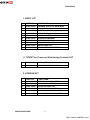
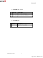
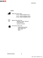
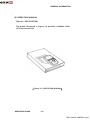
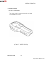
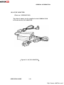
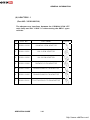
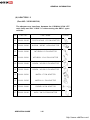
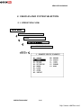
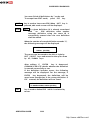
Carman Scan Lite User Manual
OPERATION MANUAL
http://www.obd2be.com/
PROLOGUE
CAUTION : Any changes or modifications in construction
of this device which is not expressly approved by the
party Responsible for compliance could void the user’s
authority to operate the equipment.
NOTE : This equipment has been tested and found to
comply with the limits for a Class A digital device,
pursuant to part 15 of the FCC Rules. The limits are
designed to provide reasonable protection against
harmful interference when the equipment is operated in
commercial environment. This equipment generates,
uses, and can radiate radio frequency energy and, if not
installed and used in accordance with the instruction
manual, may cause harmful interference to radio area is
likely to cause harmful interference in which case the
user will be required to correct the interference at his
own expense.
OPERATION GUIDE
2
http://www.obd2be.com/
PROLOGUE
TABLE of CONTENTS
SAFETY
UNPACKING
I. GENERAL INFORMATION
1. GENERAL FEATURES………………………………………..I-2
2. SPECIFICATIONS…………………………….………………I-3
3. RECHARGERABLE BATTERY……..……………….……….I-4
4. PARTS DESCRIPTION ….……..……………………..…….I-6
II. VEHICLE DIAGNOSIS
1.
2.
3.
4.
5.
6.
7.
CONNECTION METHOD……………………..….…………II-2
VEHICLE AND SYSTEM SELECTION……….……………..II-11
DIAGNOSTIC TROUBLE CODES…………………...…..…II-15
CURRENT DATA…………………………………….……...II-17
FLIGHT RECORD…………………………………….……..II-22
ACTUATION TEST…………………………………...…....II-29
IDENTIFICATION CHECK…………………………….…...II-32
III. CARB OBD-II DIAGNOSIS
1. CONNECTION METHOD…………………………………….III-2
2. COMMUNICATION INTERFACE…………………………….III-3
3. READINESS TEST………………………………….……..…..III-6
4, CURRENT DATA…………………………………….……..…III-9
5. DIAGNOSTIC TROUBLE CODES………..………………….III-13
6. FREEZE FRAME DATA……………………………………....III-16
7. EXPANDED DIAG. PROTOCOL…………………….…......III-19
8. 02 TEST RESULTS………………………………………..….III-26
9. MONITORING TEST RESULTS………………………….....III-29
10. COMBINATION DISPLAY………………………………....III-32
11. ECU INFORMATION……………………………………....III-36
12. PENDING ECU…………………………………………..….III-37
OPERATION GUIDE
3
http://www.obd2be.com/
PROLOGUE
IV. FLIGHT RECORD REVIEW
V. SYSTEM SETUP
1. CONNECTION METHOD……………………………..V-2
2. SYSTEM CONFIGURATION……………..…………...V-3
3. DATA SETUP………………………………..…..….…V-5
4. KEY PAD TEST……………………………….…..…...V-8
5. CONTRAST ADJUST SCREEN..…………….….…….V-9
VI. STORAGED SCREEN REVIEW
1. OUTLINE………………………………………………..VI-2
2. HOW TO CAPTURE ……………………..…………...VI-3
3. HOW TO DOWNLOAD……..……………..……….…VI-4
APPENDIX
A. IMPORTANT MESSAGE DESCRIPTION
B. TROUBLESHOOTING
OPERATION GUIDE
4
http://www.obd2be.com/
PROLOGUE
SAFETY
Safety Precautions
This equipment described in this manual is intended for use only
by qualified personnel. Safe and effective use of this equipment is
dependent upon the operator following normally accepted safety
practices and procedures in conjunction with the special
requirements detailed in this manual. Specific warning and cautionary
statements will be found, where applicable, throughout this manual.
Where necessary, the WARNING statements and ICON will be
described in this guide.
WARNING identifies conditions or actions which may damage
CARMAN SCAN LITE or the vehicle.
IMPORTANT WARNING MESSAGES FOR SAFETY ARE
AS FOLLOWS :
DO NOT DROP CARMAN SCAN LITE MAIN BODY.
AND CARMAN SCAN LITE MUST ALWAYS BE
COVERED BY THE SHROUD
DO NOT PLACE CARMAN SCAN LITE UPON
DISTRIBUTOR OF VEHICLE.
STRONG ELECTRO-MAGNETIC INTERFERENCE CAN
DAMAGE CARMAN SCAN LITE.
A STRONG SURGE OR ELECTRONIC SHOCK IN THE
POWER SUPPLY LINE CAN DAMAGE CARMAN SCAN
LITE POWER SUPPLY. DO NOT USE CARMAN SCAN
LITE UNDER THESE HARSH ENVIRONMENT.
OPERATION GUIDE
5
http://www.obd2be.com/
PROLOGUE
UNPACKING
The CARMAN SCAN LITE kit comprises the following
standard along with the option kit where ordered.
The kit contents should be checked upon receipt and
damage or shortages reported to the supplier
immediately.
[ Figure 0.1 : CARMAN SCAN LITE KIT ]
OPERATION GUIDE
6
http://www.obd2be.com/
PROLOGUE
1. BASIC KIT
PART NO.
PART NAME
1
20100-00100
CARMAN SCAN LITE MAIN BODY
2
20100-00200
DLC CABLE 16
3
20100-00300
CARRYING CASE
4
20100-00500
USB CABLE
5
20100-00600
CIGAR LIGHTER CABLE
6
20100-00700
OPERATION MANUAL
7
20100-00900
RUBBER SHROUD
8
20100-01000
S/W DOWNLOAD CD
9
20100-01100
AD/DC ADAPTOR
10 20100-01200
RECHAGERABLE BATTERY
2. TPMS(Tire Pressure Monitoring System) KIT
1
PART NO.
PART NAME
20100-01300
TPMS EXCITER RF MODULE
3. KOREAN KIT
PART NO.
PART NAME
1
20100-10100
HYUNDAI 12 PIN ADAPTOR
2
20100-10201
KIA 6+1 PIN ADAPTOR
3
20100-10202
KIA 20 PIN ADAPTOR
4
20100-10300
DAEWOO 12 PIN ADATOR
5
20100-10401
SSANGYOUNG 14 PIN ADATOR
6
20100-10402
SSANGYOUNG 20 PIN ADATOR
OPERATION GUIDE
7
http://www.obd2be.com/
PROLOGUE
5. JAPANESE KIT
PART NO.
PART NAME
1
20100-20101
TOYOTA/LEXUS 17R PIN ADAPTOR
2
20100-20102
TOYOTA/LEXUS 17C PIN ADAPTOR
3
20100-20200
NISSAN/INFINIT 14 PIN ADATOR
4
20100-20300
MITUBISHI 12 PIN ADATOR
5
20100-20301
MITUBISHI 12+16 PIN ADATOR
6
20100-20400
HONDA/ACURA 3 PIN ADATOR
7
20100-20401
HONDA/ACURA 5 PIN ADATOR
8
20100-20501
MAZADA 17 PIN ADATOR
9
20100-20502
MAZADA 6+1 PIN ADATOR
10 20100-20600
SUBARU 9 PIN ADAPTOR
6. EUROPEAN I KIT
PART NO.
PART NAME
1
20100-30100
AUDI/VW 2+2 PIN ADAPTOR
2
20100-30200
BMW 20 PIN ADAPTOR
3
20100-30301
BENZ 38 PIN ADAPTOR
4
20100-30302
BENZ 3 PIN ADAPTOR
5
20100-30400
OPEL 10 PIN ADAPTOR
OPERATION GUIDE
8
http://www.obd2be.com/
PROLOGUE
7. EUROPEAN II KIT
PART NO.
PART NAME
1
20100-40100
PSA 2 PIN ADAPTOR
2
20100-40101
PSA 30 PIN ADAPTOR
3
20100-40200
RENAULT 12 PIN ADAPTOR
8. OTHER KIT
PART NO.
PART NAME
1
20100-50100
HOLDEN 6 PIN ADAPTOR
2
20100-50200
FORD 20 PIN ADAPTOR
OPERATION GUIDE
9
http://www.obd2be.com/
PROLOGUE
ICON
OPERATION LEVEL ICON
: LEVEL 1 OPERATION(INIT LEVEL)
: LEVEL 1 OPERATION(MENU LEVEL)
: LEVEL 1 OPERATION(MODE LEVEL)
MESSAGE RELATED ICON
: PROCESS / RESULT MESSAGE
: ERROR MESSAGE
: WARNING MESSAGE
APPLICATION HELP ICON
: SCREEN EXPLANATION
: OPERATION GUIDE
: HELP / TIPS
: NOTE
OPERATION GUIDE
10
http://www.obd2be.com/
I.
GENERAL INFORMATION
1. GENERAL FEATURES…………………….…………….I-2
2. SPECIFICATION……………………..……..…………..1-3
3. RECHARGERABLE BATTERY…………...……………I-4
4. PARTS DESCRIPTION…………………………………I-6
http://www.obd2be.com/
GENERAL INFORMATION
1. General Features
CARMAN SCAN LITE offers the following functionality:
On board diagnostic communication
TPMS diagnostic communication
Special vehicle test emulation
This
combination
provides
for
easy
and
comprehensive diagnosis of the electronically
controlled systems used on all vehicle range.
CARMAN SCAN LITE feature include :
Diagnostic communication with KOREAN vehicle
Diagnostic communication with JAPANESE vehicle
Diagnostic communication with EUROPEAN vehicle
OBD-II communication protocol support
CAN communication protocol support
High resolution LCD display
Soft touch key
Large data storage area for TSB and Software.
Shock protecting rubber shroud
PC communication facility
PC software download with USB
OPERATION GUIDE
I-2
http://www.obd2be.com/
GENERAL INFORMATION
2. SPECIFICATION
CASING
LCD SPEC.
KEYPAD
MEMORY
CAPACITY
OPERATION
VOLTAGE
OPERATING
TEMPERATURE
DLC COMMUNICATION PART
DIMENSION
POWER
CONSUMPTION
FREQUENCY
OPERATION GUIDE
Dark gray color
High strength ABS material
320 by 240 resolution
LEDBacklight type
Standard character output :40 columns 12
Lines
Power ON /OFF Key, Soft Function 6
Keys, Arrow 4 Keys, Fixed Functional 4
Keys
NUBER 0~9 KEY(10)
Type : Soft Touch Keypad
Internal Memory :
128 Mbytes Built-in memory
7 – 36 VDC INPUT
0°C -50°C
ALL Korean Vehicle
OBD-II(ISO 9141-2)
OBD-II(SAE-J1850)
KWP-2000
CAN
SAE J1587
Width : 125mm
Length : 223mm
Depth : 68/43mm (neck part)
3.6 Watts
125KHZ, 315MHZ(AM/FM)
I-3
http://www.obd2be.com/
GENERAL INFORMATION
3. RECHARGERABLE BATTERY
3-1. USING THE BATTERY PACK
The battery pack has following characteristics.
- The battery gradually loses its power over time without
ever being used.
- Periodic full discharge/charge : Frequent recharging of the
battery pack can reduce the duration of the battery pack.
- The battery pack must be fully charged before the first
time use.
Warning
- Use only a battery pack recommended by NEXTECH.
Using a battery pack of a different type may result in
explosion.
- Keep metallic objects, such as keys and clips, away from
the battery pack.
Objects that conduct electricity can short-circuit the
battery pack and result in fire and/or injuries.
- Keep the battery pack away from heat.
There is a risk of explosion or fire.
- Do not short-circuit battery terminals.
There is a risk of explosion.
- Do not subject the battery pack to temperatures above
140 degrees F(60 degrees C)
There is a risk of explosion or fire.
- Keep the battery pack away from children and/or pet.
There is a risk of fire or damage to the battery pack.
OPERATION GUIDE
I-4
http://www.obd2be.com/
GENERAL INFORMATION
3-2. REPLACING THE BATTERY PACK
Turn the TPMS EXCITER over so that battery case faces up
and then take volt off as shown the [figure I.1].
[ figure I.1]
Take the battery case off and the replace the battery pack
as shown the [figure I.2].
[ figure I.2]
Warning
- If the backup battery is incorrectly replace, there is
danger of explosion.
- The lithium battery contains lithium and can explode if it
is not properly handled or disposed of.
- Replace only with a battery of the type recommended by
NEXTECH.
OPERATION GUIDE
I-5
http://www.obd2be.com/
GENERAL INFORMATION
4. CARMAN SCAN LITE Parts Description
(1) CARMAN SCAN LITE MAIN BODY
( Part No : 20100-00100)
The CARMAN SCAN LITE main body is illustrated in
figure I.1.
[ Figure I.1 : CARMAN SCAN LITE MAIN BODY]
OPERATION GUIDE
I-6
http://www.obd2be.com/
GENERAL INFORMATION
(2) DLC CABLE 16
(Part no : 20100-00200)
The cable is illustrated in figure I.2 and is used to connect
the main body to the diagnosis terminal of vehicles with 16
pin connector vehicles.
[ Figure I.2 : DLC CABLE 16]
OPERATION GUIDE
I-7
http://www.obd2be.com/
GENERAL INFORMATION
(3) CARRYING CASE
(Part no : 20100-00300)
The carrying case illustrated in figure I.3 provides for easy
transportation of CARMAN SCAN LITE and protection for
the unit when not in use.
[ Figure I.3 : CARRYING CASE]
OPERATION GUIDE
I-8
http://www.obd2be.com/
GENERAL INFORMATION
(4) USB CABLE
(Part no : 20100-00500)
The cable is illustrated in figure 1.4 and interfaces between
the CARMAN SCAN LITE main body and PC when S/W
download.
[ Figure I.4 : USB CABLE ]
OPERATION GUIDE
I-9
http://www.obd2be.com/
GENERAL INFORMATION
(5) CIGAR LIGHTER POWER CABLE
(Part no : 20100-00600)
The cable is illustrated in figure 1.5 and is used to provide
the CARMAN SCAN LITE main body with power from the
vehicle cigar lighter socket.
[ Figure 1.5 : POWER EXTENSION CABLE]
OPERATION GUIDE
I-10
http://www.obd2be.com/
GENERAL INFORMATION
(6) OPERATION MANUAL
(Part no : 20100-00700)
The guide, illustrated in figure 1.6 provides CARMAN SCAN
LITE user Instruction.
[ Figure I.6 : OPERATION MANUAL]
OPERATION GUIDE
I-11
http://www.obd2be.com/
GENERAL INFORMATION
(7) RUBBER SHROUD
(Part NO : 20100-00900)
The rubber shroud is used to protect the main body
from damage when in use.
[ Figure I.7 : RUBBER SHROUD]
OPERATION GUIDE
I-12
http://www.obd2be.com/
GENERAL INFORMATION
(8) AC/DC ADAPTOR
(Part no : 20100-01100)
The electric power can be supplied to the CARMAN SCAN
LITE with the AC/DC ADAPTOR.
[ Figure I.8 : AC/DC ADAPTOR]
OPERATION GUIDE
I-13
http://www.obd2be.com/
GENERAL INFORMATION
(9) ADAPTORS -1
(Part NO : 20100-XXXXX)
The adaptors are interfaces between the CARMAN SCAN LITE
main body and DLC CABLE 16 when testing the OBD-1 types
vehicles.
NO
PART NO.
PART NAME
1
20100-10100
HYUNDAI 12PIN ADAPTOR
2
20100-10201
KIA 6+1PIN ADAPTOR
3
20100-10202
KIA 20 PIN ADAPTOR
4
20100-10300
DAEWOO 12 PIN ADAPTOR
5
20100-10401
SSANGYOUNG 14 PIN ADAPTOR
6
20100-10402
SSANGYOUNG 20 PIN ADAPTOR
7
20100-20101
TOYOTA/LEXUS 17R PIN ADAPTOR
OPERATION GUIDE
FIGURE
I-14
http://www.obd2be.com/
GENERAL INFORMATION
(9) ADAPTORS -2
(Part NO : 20100-XXXXX)
The adaptors are interfaces between the CARMAN SCAN LITE
main body and DLC CABLE 16 when testing the OBD-1 types
vehicles.
NO
PART NO.
PART NAME
8
20100-20102
TOYOTA/LEXUS 17C PIN ADAPTOR
9
20100-20200
NISSAN / INFINIT 14PIN ADAPTOR
10
20100-20300
MITUBISHI 12 PIN ADAPTOR
11
20100-20301
MITUBISHI 12+16 PIN ADAPTOR
12
20100-20400
HONDA / ACURA 3 PIN ADAPTOR
13
20100-20401
HONDA / ACURA 5 PIN ADAPTOR
14
20100-20501
MAZDA 17 PIN ADAPTOR
15
20100-20502
MAZDA 6+1 PIN ADAPTOR
16
20100-20600
SUBARU 9 PIN ADAPTOR
17
20100-30100
AUDI / VW 2+2 PIN ADAPTOR
OPERATION GUIDE
FIGURE
I-15
http://www.obd2be.com/
GENERAL INFORMATION
(9) ADAPTORS -3
(Part NO : 20100-XXXXX)
The adaptors are interfaces between the CARMAN SCAN LITE
main body and DLC CABLE 16 when testing the OBD-1 types
vehicles.
NO
PART NO.
PART NAME
18
20100-30200
BMW 20 PIN ADAPTOR
19
20100-30301
BENZ 38 PIN ADAPTOR
20
20100-30302
BENZ 3 PIN ADAPTOR
21
20100-30400
OPEL 10 PIN ADAPTOR
22
20100-40100
PSA 2 PIN ADAPTOR
23
20100-40101
PSA 30 PIN ADAPTOR
24
20100-40200
RENAULT 12 PIN ADAPTOR
25
20100-50100
HOLDEN 6 PIN ADAPTOR
26
20100-50200
FORD 20 PIN ADAPTOR
OPERATION GUIDE
FIGURE
I-16
http://www.obd2be.com/
II. VEHICLE DIAGNOSIS
1. CONNECTION METHOD………………………..……………II-2
2. VEHICLE AND SYSTEM SELECTION………..…..…………..II-11
3. DIAGNOSTIC TROUBLE CODES…………..………..………II-15
4. CURRENT DATA……………………………………….……….II-17
5. FLIGHT RECORD……………………………………………….II-22
6. ACTUATION TEST………………………………….………....II-29
7. IDENTIFICATION CHECK…………………………….……...II-32
http://www.obd2be.com/
VEHICLE DIAGNOSIS
1. CONNECTION METHOD
1) HYUNDAI VEHICLE
For vehicles with 16 pin Data Link Connector power is
supplied from the DLC terminal through the DLC CABLE.
An additional power supply is not needed. For these
vehicles, connection of the DLC CABLE 16 to CARMAN
SCAN LITE and the vehicle data link terminals is all that
is required.
However, only the latest generation of vehicles (97 and
on) use the 16-pin Data Link Connector. For earlier
models, a separate power supply by means of the cigar
lighter cable will be required.
For earlier vehicles (pre 97), diagnostic connector can
be found at the relay box which is located at knee
bolster or fuse box located at the out side of driver’s
side.
For current vehicles (97 and on), Diagnostic connector
can be found underneath the driver’s side knee bolster.
Once the power supply has been connected, the DLC
CABLE 16 should be connected to CARMAN SCAN LITE
data link terminal and the DLC CABLE ADAPTER 16-12
connected to the vehicle data link terminal and the DLC
CABLE 16.
OPERATION GUIDE
II-2
http://www.obd2be.com/
VEHICLE DIAGNOSIS
2) KIA VEHICLE
For vehicles with 20 pin Data Link Connector, power is
supplied from the DLC terminal through the DLC CABLE
without the need for an additional power supply.
For these vehicles connection of the DLC CABLE 20 to
the CARMAN SCAN LITE and the vehicle data link
terminals is all that is required.
However in case of 6 pin data link connector, a separate
power supply by means of the cigar lighter cable will
be required for earlier models.
Diagnostic connector for vehicle with 20 pin or 6 pin can
be found in the engine bay. Some are found near engine
bulkhead and some are near battery.
For current vehicles (after 2000 and on), OBD-II DLC 16
pin connector is used and can be found underneath the
driver side knee bolster.
Once the power supply has been connected, the DLC
CABLE 16 should be connected to CARMAN SCAN LITE
data link terminal and the DLC CABLE ADAPTER
connected to the vehicle data link terminal and the DLC
CABLE 16.
OPERATION GUIDE
II-3
http://www.obd2be.com/
VEHICLE DIAGNOSIS
3) TOYOTA VEHICLE
For vehicles with 16 pin Data Link Connector power is
supplied from the DLC terminal through the DLC CABLE.
An additional power supply is not needed. For these
vehicles, connection of the DLC CABLE 16 to the
CARMAN SCAN LITE
and the vehicle data link
terminals is all that required.
However, the latest generation of vehicles for US
market(96 and on) uses the 16-pin Data Link Connector.
Vehicles with Rectangular connector doesn’t require
additional power supply, but for semi-circular,
additional power supply is required.
For earlier vehicles and Japan domestic vehicles with
rectangular, diagnostic connector can be found in the
engine bay, usually right side of the vehicle, seen from
front of the vehicle. But some vehicles with rectangular
connector, additional diagnostic connector of semicircular connector can be found underneath the
dashboard.
After 96 model year, vehicles for outside of Japanese
market are usually equipped with OBD-II connector and
can be found underneath the driver’s side knee bolster.
Once the power supply has been connected, the DLC
CABLE 16 should be connected to CARMAN SCAN LITE
data link terminal and the DLC CABLE ADAPTER should
be connected to the vehicle data link terminal, if
required, and the DLC CABLE 16.
OPERATION GUIDE
II-4
http://www.obd2be.com/
VEHICLE DIAGNOSIS
4) HONDA VEHICLE
For vehicles with 16 pin and 3 pin Data Link Connector,
power is supplied from the DLC terminal through the
DLC CABLE. An additional power supply is not needed.
For these vehicles, connection of the DLC ADAPTER 16
pin to the CARMAN SCAN LITE and the vehicle data link
terminals is all that required.
For earlier vehicles and Japan domestic vehicles with
3pin connector, diagnostic connector can be found in
the driver or passenger side cabin underneath the knee
bolster.
After 96 model year, vehicles are usually equipped with
OBD-II connector and can be found underneath the
driver’s side knee bolster.
Once the power supply has been connected, the DLC
CABLE 16 should be connected to CARMAN SCAN LITE
data link terminal and the DLC CABLE ADAPTER should
be connected to the vehicle data link terminal, if
required, and the DLC CABLE 16.
OPERATION GUIDE
II-5
http://www.obd2be.com/
VEHICLE DIAGNOSIS
5) NISSAN VEHICLE
For vehicles with 16 pins and 14 pins Data Link
Connector power is supplied from the DLC terminal
through the DLC CABLE. An additional power supply is
not needed.
For earlier vehicles and Japan domestic vehicles with
14pin connector, diagnostic connector can be found in
the driver’s door side cabin or fuse box underneath the
knee bolster.
After 96 model year, vehicles are usually equipped with
OBD-II connector and can be found underneath the
driver’s side knee bolster.
The DLC CABLE 16 should be connected to CARMAN
SCAN LITE data link terminal and the DLC CABLE
ADAPTER should be connected to the vehicle data link
terminal.
OPERATION GUIDE
II-6
http://www.obd2be.com/
VEHICLE DIAGNOSIS
6) MISTUBISHI VEHICLE
For vehicles with 16 pin Data Link Connector power is
supplied from the DLC terminal through the DLC CABLE.
An additional power supply is not needed.
However, only the latest generation of vehicles for US
market(96 and on) uses the 16-pin Data Link Connector.
For earlier models, a separate power supply by means
of the cigar lighter cable will be required.
For earlier vehicles and Japan domestic vehicles with
12pins connector, diagnostic connector can be found in
the fuse box located at the driver’s door side panel.
After 96 model year, vehicles are usually equipped with
OBD-II connector and can be found underneath the
driver’s side knee bolster.
Once the power supply has been connected, the DLC
CABLE 16 should be connected to CARMAN SCAN LITE
data link terminal and the DLC CABLE ADAPTER should
be connected to the vehicle data link terminal, if
required, and the DLC CABLE 16.
OPERATION GUIDE
II-7
http://www.obd2be.com/
VEHICLE DIAGNOSIS
7) MAZDA VEHICLE
For vehicles with 16 pin Data Link Connector power is
supplied from the DLC terminal through the DLC CABLE.
An additional power supply is not needed. For these
vehicles, connection of the DLC CABLE 16 to the
CARMAN SCAN LITE and the vehicle data link terminals
is all that required.
However, only the latest generation of vehicles for US
market(96 and on) uses the 16-pin Data Link Connector.
For earlier vehicles and Japan domestic vehicles with
17pin connector, diagnostic connector can be found in
the engine bay, usually right side of the vehicle, seen
from front of the vehicle.
After 96 model year, vehicles are usually equipped with
ODB-II connector and can be found underneath the
driver’s side knee bolster.
Once the power supply has been connected, the DLC
CABLE 16 should be connected to CARMAN SCAN LITE
data link terminal and the DLC CABLE ADAPTER should
be connected to the vehicle data link terminal, if
required, and the DLC CABLE 16.
OPERATION GUIDE
II-8
http://www.obd2be.com/
VEHICLE DIAGNOSIS
8) MERCEDES BENZ VEHICLE
It supports 4 types
Mercedes vehicle.
of
diagnosis
connectors
in
BENZ 3 PIN ADAPTOR can diagnose Benz’s 8 pole, 16
pole type connectors. BENZ 38 PIN ADAPTOR can
diagnose Benz’s 38 pin type connectors. And then if
the vehicle is equipped with 16 pin OBD-II DLC, connect
the DCL CABLE 16 directly to the vehicle.
You can check the methods of connecting with vehicle
on the CARMAN SCAN LITE screen.
The vehicle with 16 pole, 38 pin, 16 pin type diagnosis
connector doesn’t require additional power supply,
but for 8 pole type, additional power supply is
required.
The vehicles with 8 pole, 16 pole, 38 pin diagnostic
connector can be found in the engine bay.
Some vehicles are equipped with OBD-II connector and
can be found underneath the driver’s side or passenger
side knee bolster.
Once the power supply has been connected, the DLC
CABLE 16 should be connected to CARMAN SCAN LITE
data link terminal and the DLC CABLE ADAPTER should
be connected to the vehicle data link terminal, if
required, and the DLC CABLE 16.
OPERATION GUIDE
II-9
http://www.obd2be.com/
VEHICLE DIAGNOSIS
9) BMW VEHICLE
For vehicles with 16 pin and 20 pin Data Link
Connector, power is supplied from the DLC terminal
through the DLC CABLE. An additional power supply is
not needed. For these vehicles, connection of the DLC
ADAPTER 16 pin to the CARMAN SCAN LITE and the
vehicle data link terminals is all that required.
For earlier vehicles with 20pin connector, diagnostic
connector can be found in the engine bay.
After 2000, vehicles are usually equipped with OBD-II
connector and can be found underneath the driver’s
side knee bolster.
Once the power supply has been connected, the DLC
CABLE 16 should be connected to CARMAN SCAN LITE
data link terminal and the DLC CABLE ADAPTER should
be connected to the vehicle data link terminal, if
required, and the DLC CABLE 16.
OPERATION GUIDE
II-10
http://www.obd2be.com/
VEHICLE DIAGNOSIS
2. VEHICLES AND SYSTEM SELECTION
2-1. OPERATION FLOW
INITIAL MENU
VEHICLE DIAGNOSIS
JAPAN
0.1 INITIAL SCREEN
0.1
VEHICLE DIAGNOSIS
ENTER
OPERATION GUIDE
II-11
http://www.obd2be.com/
VEHICLE DIAGNOSIS
ENTER
ENTER
OPERATION GUIDE
II-12
http://www.obd2be.com/
VEHICLE DIAGNOSIS
ENTER
ENTER
[FLOW 1 : VEHICLE AND SYSTEM SELECTION SUB-MENU IN/OUT
FLOW ]
OPERATION GUIDE
II-13
http://www.obd2be.com/
VEHICLE DIAGNOSIS
2-2. BASIC APPLICATION
Having connected and turned on CARMAN SCAN
LITE, the vehicle and systems 1 and 2 selections
must be made from the [ 1.0 VEHICLE DIAGNOSIS]
screen.
The support functions differ from vehicle to
vehicle and therefore the correct selection must
be made. Selection can be made by scrolling up or
down the screen and pressing ENTER.
Selection is made in the order of VEHICLE, SYSTEM
1, and SYSTEM 2.
OPERATION GUIDE
II-14
http://www.obd2be.com/
VEHICLE DIAGNOSIS
3. DIAGNOSTIC TROUBLE CODES
3-1. OPERATION FLOW
01. INITIAL SCREEN
01
VEHICLE AND SYSTEM SELECTION
Refer to “Selecting Vehicle Mode”
0.1 DIAGNOSTIC TROUBLE CODES
ENTER
ERAS
1.1.2 ERASE FAULT CODE
[ FLOW 2 : DIAGNOSTIC TROUBLE CODES IN/OUT FLOW]
OPERATION GUIDE
II-15
http://www.obd2be.com/
VEHICLE DIAGNOSIS
3-2. MODE APPLICATION
At this level, diagnostic trouble codes (DTC) are displayed for
the selected ECM
Whenever the screen is opened or refreshed, the cursor
moves to the beginning of the display and an audible
warning will be given along with the number and description
of the component from which the code has been generated.
By using the UP / DOWN key, the display may be scrolled.
EARS
This soft function key will clear the DTC currently
held in the memory of the selected ECM. If this
option is selected, a message requesting
confirmation of the ERAS request will be displayed.
The ENTER or ESC key should be used to confirm
or cancel the request to clear the current DTC.
To erase the MIL type DTCs, disconnect the battery
terminal for 15 second or more.
OPERATION GUIDE
II-16
http://www.obd2be.com/
VEHICLE DIAGNOSIS
4. CURRENT DATA
4-1. OPERATION FLOW
01. INTIAL SCREEN
01
VEHICLE AND SYSTEM SELECTION
Refer to ‘Selecting Vehicle Mode”
0.2 CURRENT DATA
ENTER
FIX
SCRN
FULL
GRPH
1.2.1 FIX ITEM
1.2.2 SPLIT SCREEN
1.2.3 DISPLAY ALL ITEMS
1.2.5 GRAPHICAL DISPLAY
[ FLOW 3 : CURRENT DATA MODE IN/OUT FLOW ]
OPERATION GUIDE
II-17
http://www.obd2be.com/
VEHICLE DIAGNOSIS
4-2. MODE APPLICATION
The sensor values and the ON/OFF state of the
system switches of the selected ECM are displayed.
Scrolling up and
down the data is possible by
means of the UP / DOWN keys and more detailed
data is available by Using the soft function keys as
follows :
FIX
Executing the [I.2.I FIX ITEM] function that moves
the item in inverted text to the top of the display.
This item is held and does not move when the
cursor keys are used to page through the display
and therefore allows specific items to be
compared directly to one another.
[ Figure 1 : FIX ITEM ]
OPERATION GUIDE
II-18
http://www.obd2be.com/
VEHICLE DIAGNOSIS
A fixed item may be released by depressing the
FIX key again.
In the example, illustrated by figure 1, is fixed as
denoted by the asterisk to the left of the item
number.
SCRN
Pressing this key will change the number of
displayed sensors or switch state which are
‘active’ from 8(MAX), 4, or 2(MIN). Where only 2
items are ‘active’, the rate at which CARMAN SCAN
LITE update the display data will be faster than
where a higher number of ‘active’ items are
selected.
In the example illustrated by figure 2, only 2
‘active’ data items are selected
[Figure 2 : Split screen]
OPERATION GUIDE
II-19
http://www.obd2be.com/
VEHICLE DIAGNOSIS
FULL
Use of this key will cause maximum 22 data
value to be displayed on the screen as illustrated
in figure 3. The component description displayed
will be abbreviated when this mode is used. The
date may be scrolled by use of the UP / DOWN
key.
[ Figure 3 : DISPLAY ALL ITEMS ]
OPERATION GUIDE
II-20
http://www.obd2be.com/
VEHICLE DIAGNOSIS
GRPH
Where more
2 ‘active’ data
items have been
selected using the FIX key, pressing the GRPH key
will cause the data for those items to be displayed
in the form of a graph as illustrated in figure 4.
FIX
Holding one item of two. When the UP / DOWN keys
are used to scroll up and down the display, the
item selected by FIX key does not move.
[Figure 4 : CURRENT DATA (GRPH)]
OPERATION GUIDE
II-21
http://www.obd2be.com/
VEHICLE DIAGNOSIS
5. FLIGHT RECORD
5-1 OPERATION FLOW
0.1 INITIAL SCREEN
01
VEHICLE AND SYSTEM SELECTION
Refer to “ Selecting Vehicle Mode”
0.3 FLGHT RECORD
ENTER
FIX
1.3.1 FIX ITEM
CALL
1.3.2 CALL MEMORIZED DATA
RCRD
1.3.3 START RECORD
[ FLOW 4 : FLIGHT RECORD MODE IN/OUT FLOW]
OPERATION GUIDE
II-22
http://www.obd2be.com/
VEHICLE DIAGNOSIS
5-2 . MODE APPLICATION
The FLIGHT RECORD mode allows for the display and
recording of data generated by the ECM as determined
by the user of CARMAN SCAN LITE .
By using the UP / DOWN key, the display may be
scrolled.
The function of the FLIGHT RECORD is determined by
the following soft function keys :
FIX
This soft function key selects or releases the items
for which data is to be recorded. The fixed are
identified by means of an asterisk to the left of the
item number on the CARMAN SCAN LITE screen. The
maximum number of items, which may be selected
for FLIGHT RECORD functions, is 8.
The data sampling time interval is displayed at the
center of the bottom line of the screen.
CALL
This function is used to replay the recorded data.
Stored data is only overwritten when recording and
therefore the same data can be viewed more than
once/without being over written provided that no
recording takes place.
If the stored file to be viewed relates to vehicle or
system, which differs from the current vehicle and
system selection, or if no recording data, the
following message will be displayed.
NO RECORDED DATA OR
DIFFERENT SYSTEM DATA.
OPERATION GUIDE
II-23
http://www.obd2be.com/
VEHICLE DIAGNOSIS
The message is displayed on the screen as shown in
Figure 5. The user can select one of the items to read.
[ Figure 5 : FLIGHT RECORD (CALL) ]
MEMORY 1 and MEMORY 4, each memory indicates built-in
memory of CARMAN SCAN LITE.
If data is in the selected memory, stored data will be
displayed , But the following message will be displayed if
the ID of the stored record is different from that of
current vehicle and system selection or if no recorded
data.
NO RECORDED DATA OR
DIFFERENT SYSTEM DATA
OPERATION GUIDE
II-24
http://www.obd2be.com/
VEHICLE DIAGNOSIS
RCRD end when either the END or ESC key is depressed.
During the recording function, the screen takes the
appearance of that illustrated in [ figure 6 ]
If the quantity of data being recorded exceeds the
capacity of the CARMAN SCAN LITE memory, the
first recorded data of the current session will be
progressively overwritten as recording continues
[ Figure 6. FLIGHT RECORD (RECORDING) ]
The message is displayed on the screen as in the
following figure.
OPERATION GUIDE
II-25
http://www.obd2be.com/
VEHICLE DIAGNOSIS
[ Figure 7 : FLIGHT RECORD (RCRD) ]
MEMORY 1 and MEMORY 4, each memory indicates internal
memory of CARMAN SCAN LITE.
If user selects memory, [ Figure 7 ] is display. If this key is
pressed without selected items, the following message is
displayed.
SELECT ITEM WITH[FIX]
OPERATION GUIDE
II-26
http://www.obd2be.com/
VEHICLE DIAGNOSIS
TRIG
This key is used to set trigger point in this
recording process.
When TRIG key is depressed more than twice , only
the latest TRIG key handled as trigger at trigger
point.
If END key or ESC key is depressed before TRIG
key , that time becomes the trigger point and
recording will be ended.
After finishing the recording, screen will display
stored data values in a numeric data form. The
screen example is as follows:
[ Figure 8 : FLIGHT RECORD (NUMERIC) ]
OPERATION GUIDE
II-27
http://www.obd2be.com/
VEHICLE DIAGNOSIS
In this numerical data display, GRPH key is used to
see Graphic views for the items recorded by FIX key
operation.
If the two items are selected, a graphical view is as
follows.
[ Figure 9 : FLIGHT RECORD (GRAPH) ]
[ T+5 ] MEANS SAMPLED TIME INDEX, AND
CURRENT SCREEN DISPLAY THE TIME AFTER 5TH
SAMPLING INDEX FROM TRIGGER POINT.
You can change sampled time index by LEFT(◄) or
RIGHT(►) key. In graphic display, current sampled
time index position is displayed as vertical line cursor.
If this cursor is arrived end of screen, screen will be
moved as half page.
OPERATION GUIDE
II-28
http://www.obd2be.com/
VEHICLE DIAGNOSIS
6. ACTUATION TEST
6-1 OPERATION FLOW
JAPAN
NISSAN AND ENGINE SELECTION
Refer to “ Selecting Vehicle Mode “
04. ACTUATION TEST
ENTER
START
START ACTIVATING
[ FLOW 5 : ACTUATION TEST MODE IN/OUT FLOW ]
OPERATION GUIDE
II-29
http://www.obd2be.com/
VEHICLE DIAGNOSIS
6-2 MODE APPLICATION
The ACTUATION TEST mode allows certain actuators to be
forcibly driven by CARMAN SCAN LITE but this mode can
only be supported according to the selected vehicle. The
illustration of a typical screen is shown in [ figure 10 ] .
The actuator to be driven can be changed by using the UP /
DOWN key to scroll through the list.
[ Figure 10 : ACTUATOR DRIVING ]
The test must be performed with the vehicle in the state
indicated by the CONDITION statement on the screen. In
this illustration given, for example, the ignition key must
be turned “on”, and the engine must be running.
The duration of the test will either be fixed by CARMAN
SCAN LITE and indicated on the screen or the duration
dialogue will indicate
OPERATION GUIDE
II-30
http://www.obd2be.com/
VEHICLE DIAGNOSIS
UNTIL STOP KEY
To begin an actuator test, the STRT key should be
pressed. For fixed duration test, the message
COMPLETED!
will be display after an acknowledged code has been
received from the vehicle. For tests of no fixed
duration, the message
NOW ACTIVATING
will be displayed once an acknowledged code has been
received from the vehicle and until the STOP key is
pressed. In both types of test, the message
TEST FAILURE!
will be displayed if no acknowledge code is received
from the Vehicle. The messages will be displayed for
0.5 seconds and then disappear.
OPERATION GUIDE
II-31
http://www.obd2be.com/
VEHICLE DIAGNOSIS
7. IDENTIFICATION CHECK
7-1. OPERATION FLOW
HYUNDAI
HUNDAI AND ENGINE SELECTION
Refer to “ Selecting Vehicle Mode “
0X. IDENTIFICATION CHECK
[ FLOW 6 : IDENTIFICATION CHECK ]
Right after IDENTIFICATION CHECK mode is accessed, Part
number and Software Version number will be displayed
automatically.
OPERATION GUIDE
II-32
http://www.obd2be.com/
III. CARB OBD-II DIAGNOSIS
1. CONNECTION METHOD……………………………III-2
2. COMMUNICATION INTERFACE…………………..III-3
3. READINESS TEST……………………….………..….III-6
4, CURRENT DATA………………………………..…...III-9
5. DIAGNOSTIC TROUBLE CODES………………....III-13
6. FREEZE FRAME DATA………………………….….III-16
7. EXPANDED DIAG. PROTOCOL…………………..III-19
8. 02 TEST RESULTS…………………………..…..…III-26
9. MONITORING TEST RESULTS…………….…….III-29
10. COMBINATION DISPLAY………………………..III-32
11. ECU INFORMATION………………………………III-36
12. PENDING ECU………………………….…..………III-37
http://www.obd2be.com/
CARB OBD-II DIAGNOSIS
1. CONNECTION METHOD
For vehicles with OBD-II communications protocol, power
is supplied from the DLC terminal through the DLC cable
without the need for an additional power supply.
For these vehicles connection of the DLC CABLE 16 to
the CARMAN SCAN LITE and the vehicle data link
terminals is all that is required.
OPERATION GUIDE
III-2
http://www.obd2be.com/
CARB OBD-II DIAGNOSIS
2. COMMUNICATION INTERFACE
2-1. OPERATION FLOW
0.1 VEHICLE DIAGNOSIS SCREEN
02
Success in First initializing
2.0 CARB OBD-II DIAGNOSIS
Failure in First initializing
REPETITION OF INITIALZING
PROCEDURE
[ FLOW III.1 : COMM. INITIAL SUB-MSR IN/OUT FLOW ]
OPERATION GUIDE
III-3
http://www.obd2be.com/
CARB OBD-II DIAGNOSIS
2-2. MODE APPLICATION
When CARB OBD-II DIAGNOSIS is selected, CARMAN
SCAN LITE automatically searches for vehicle interfaces
that apply to OBD-II functions.
During initialization, a process message is displayed. If
the initialization fails because no interfaces have been
found, CARMAN SCAN LITE repeats the initialization
process and displays the following message. The user
may terminate this process by pressing ESC
RETRY 1 TIMES
When a communication interface is located, CARMAN
SCAN LITE displays the figure III.2 or III.3 according to
the result of the on board- system-readiness-tests.
[Figure III.2 : INITIALIZATION (NOT COMPLETED) ]
OPERATION GUIDE
III-4
http://www.obd2be.com/
CARB OBD-II DIAGNOSIS
[ Figure III.3 : INITIALIZATION (COMPLETED) ]
OPERATION GUIDE
III-5
http://www.obd2be.com/
CARB OBD-II DIAGNOSIS
3. READINESS TEST
3-1 OPERATION FLOW
0.1 VEHICLE DIAGNOSIS SCREEN
02
Automatic Search for communication Interface
Refer to “Searching for Communication Interface”
2.0 CARB OBD II DIAGNOSIS
01
DMID
3.1.1 DISPLAY MODULE ID
SMID
3.1.2 SELECT MODULE
[ FLOW III.2 : READINESS TEST MODE IN/OUT FLOW ]
OPERATION GUIDE
III-6
http://www.obd2be.com/
CARB OBD-II DIAGNOSIS
3-2. MODE APPLICATION
The type and result of the READINESS TESTS supported
by more than one MODULE within the vehicle will be
displayed.
And the number of DTC and the state of
MIL(Malfunction Indicator Lamp) are displayed.
Where several modules respond to each TEST, the
number of responding modules along with an indicator
will be displayed. The indicator takes the form of an ’∗’
or ’#’ symbol.
indicates that two or more modules
have responded with the same value.
‘#’ indicates that two or more modules
have responded with different values.
’∗’
A typical illustration of the readiness TEST appears at
figure III.4
[ Figure III.4 : READINESS TEST ]
OPERATION GUIDE
III-7
http://www.obd2be.com/
CARB OBD-II DIAGNOSIS
Using the UP / DOWN key permits scrolling of the
displayed data.
DMID
Displaying the Module ID of the test item
selected by UP / DOWN key.
SMID
Displaying the supporting items, sorted
according to the module ID. A typical screen
display is illustrated at figure III.5.
[ Figure III.5:READINESS TEST(SMID) ]
If you want to know items corresponding to another Module ID,
move cursor to display area of Module ID with LEFT key, and
then use UP / DOWN key to select Module ID and press
ENTER key.
ESC
Causes the display to return.
OPERATION GUIDE
III-8
http://www.obd2be.com/
CARB OBD-II DIAGNOSIS
4. CURRENT DATA
4-1. OPERATION FLOW
0.1 VEHICLE DIAGNOSIS SCREEN
02
Automatic Search for communication Interface
Refer to “Searching for Communication Interface”
2.0
CARB OBD II DIAGNOSIS
02
DMID
3.2.1 DISPLAY MODULE ID
SMID
3.2.2 SELECT MODULE
SPID
3.2.3 SELECT PID
[ FLOW III.3 : CURRENT DATA MODE IN/OUT FLOW ]
OPERATION GUIDE
III-9
http://www.obd2be.com/
CARB OBD-II DIAGNOSIS
4.2
MODE APPLICATION
The CURRENT DATA MODE allows for sensor values
and switch states to be displayed, based upon the
concept that one item may be supported by several
modules. Supporting module information is displayed
in this mode.
A typical CURRENT DATA screen display appears at
figure III.6.
[ Figure III.6 : CURRENT DATA ]
OPERATION GUIDE
III-10
http://www.obd2be.com/
CARB OBD-II DIAGNOSIS
CARMAN SCAN LITE display all of the PID names
supported by several modules and the status in the
center column of the display. In the left hand column,
an indicator is displayed. The indicator takes the form
of an ‘*’ , ’#’ or ’-‘ symbol.
‘*’ indicates that two or more modules
have responded with the same value.
‘#’ indicates that two or more modules
have responded with different values.
‘-‘ indicates no response from two or more
modules.
The UP / DOWN key can be used to scroll through the
data to highlight items to be activated by soft function
keys.
DMID
Displaying the Module IDs for the selected item.
The UP / DOWN key may be used to scroll through
the data.
SMID
Displaying the supported items sorted according to
Module ID. Using this function it is possible to view
the module ID supporting an item group.
If you want to know items corresponding to another
Module ID, move cursor to display area of Module
ID with LEFT Key, and then use UP / DOWN key to
select Module ID and press ENTER key.
OPERATION GUIDE
III-11
http://www.obd2be.com/
CARB OBD-II DIAGNOSIS
SPID
This function allows for selective data display
based upon user selection of the required data.
Moving the cursor to the required line(s) and
pressing the soft function key. SLCT .
Once all of the required items have been selected,
pressing ENTER will cause them to be displayed.
Selected items are marked with an asterisk. Items
can be deselected by depressing
SLCT key
again.
Pressing
ENTER
display all items.
without item selection will
[ Figure III.6 : CURRENT DATA(SPID) ]
OPERATION GUIDE
III-12
http://www.obd2be.com/
CARB OBD-II DIAGNOSIS
5. DIAGNOSTIC TROUBLE CODES
5-1. OPERATION FLOW
0.1 VEHICLE DIAGNOSIS SCREEN
02
Automatic Search for communication Interface
Refer to “Searching for Communication Interface”
2.0 CARB OBD II DIAGNOSIS
03
SMID
3.3.1
SELECT MODULE
ERAS
3.3.2 CLEAR FAULT CODES
[ FLOW III.4 : DIAGNOSTIC TROUBLE CODES MODE IN/OUT FLOW ]
OPERATION GUIDE
III-13
http://www.obd2be.com/
CARB OBD-II DIAGNOSIS
I5-2. MODE APPLICATION
At this level, DIAGNOSTIC TROUBLE CODES (DTC)
are displayed based upon the concept that one DTC
may be supported by several modules. Supporting
module information is displayed in this mode.
[ Figure III.8: DTC SCREEN ]
By using the UP / DOWN key, CARMAN SCAN LITE
displays all of the DTCs supported by several
modules and the status.
SMID
Displaying the DTCs sorted according to module ID.
Using this function it is possible to view the
Module ID supporting a DTC group.
OPERATION GUIDE
III-14
http://www.obd2be.com/
CARB OBD-II DIAGNOSIS
If you want to know DTCs corresponding to another
Module ID, move cursor to display area of Module ID
with LEFT key, and then use UP / DOWN key to
select Module ID and press ENTER key.
ERAS
This soft function key will clear the DTC currently
held in the memory of ECM. If this option is
selected, all message requesting confirmation of
the ERAS request will be displayed.
NOTE THAT ALL MODULES MUST BE IN THE
“IGNITION ON, ENGINE OFF” MODE FOR CARMAN
SCAN LITE TO BE ABLE TO ERASE DTCs. IF ANY
OTHER CONDITION EXISTS. CARMAN SCAN LITE
WILL NOT ERASE CODES.
OPERATION GUIDE
III-15
http://www.obd2be.com/
CARB OBD-II DIAGNOSIS
6. FREEZE FRAME DATA
6-1. OPERATION FLOW
0.1 VEHICLE DIAGNOSIS SCREEN
02
Automatic Search for communication Interface
Refer to “Searching for Communication Interface”
2.0 CARB OBD II DIAGNOSIS
04
DMID
3.4.1 DISPLAY MODULE ID
SMID
3.4.2 SELECT MODULE
SPID
3.4.3 SELECT PID
[ FLOW III.5 : FREEZE FRAME DATA MODE IN/OUT FLOW ]
OPERATION GUIDE
III-16
http://www.obd2be.com/
CARB OBD-II DIAGNOSIS
6-2. MODE APPLICATION
The FREEZE FRAME DATA displays the data values
stored in the ECM at the point when the first DTC is
detected.
A typical screen display is illustrated at figure III.9.
[ Figure III.9:FREEZE FRAME DATA ]
CARMAN SCAN LITE displays all of the Freeze Frame
Data for those items supported by several modules
and the status in the center column of the display.
In the left hand column, an indicator is displayed.
The indicator takes the form of a ’*’, ‘#’ or ‘-‘ symbol.
‘*’ indicate that two or more modules
have responded with the same value.
OPERATION GUIDE
III-17
http://www.obd2be.com/
CARB OBD-II DIAGNOSIS
‘#’ indicate that two or more modules have
responded with different values.
‘-‘ indicate no response from two or more
modules.
The UP / DOWN key can be used to scroll through
the data to highlight items to be activated by soft
function keys.
DMID
is used to display the Module Ids for the selected
item. The UP / DOWN key may be used to
scroll through the data.
SMID
is used to display the supported items sorted
according to module ID. Using this function it is
possible to view the module ID supporting an item
group.
If you want to know items corresponding to another
Module ID, move cursor to display area of Module ID
with LEFT key, and then use UP / DOWN key to
select Module ID and press ENTER key.
SPID
This function allows for selective data display
based upon required line(s) and press of the soft
function key. Once all of the required items have
been selected, pressing ENTER will cause them to
be displayed. Selected items art marked with an
asterisk. Items can be deselected by depressing
SLCT key again.
OPERATION GUIDE
III-18
http://www.obd2be.com/
CARB OBD-II DIAGNOSIS
7. EXPANDED DIAG. PROTOCOL
7-1. OPERATION FLOW
0.1 VEHICLE DIAGNOSIS SCREEN
02
Automatic Search for communication Interface
Refer to “Searching for Communication Interface”
2.0 CARB OBD II DIAGNOSIS
05
EDIT
INST
DEL
RUN
3-5.1
3-5.2
3-5.3
3-5.4
EDIT EDP
INSERT NEW EDP
DELETE EDP
RUN EDP
[ FLOW III.6 : EXPANDED DIAG. PROTOCOL MODE IN/OUT FLOW]
OPERATION GUIDE
III-19
http://www.obd2be.com/
CARB OBD-II DIAGNOSIS
7-2. MODE APPLICATION
The purpose of EXPANDED DIAG. PROTOCOL(herein-after “EDP”) is to define encoding techniques
which can perform the following functions.
1) Function that describes the messages to be
transmitted to the vehicle and the transmitting
method to SAE J1978 OBD II Scan Tool.
2) Function that describes the message that scan
tool will receive and process to SAE J1978 OBD
II Scan Tool.
3) Function that describes the way to process the
data included in the received messages to SAE
J1978 OBD II Scan Tool.
In EDP definition, there are generally 4 groups:
control type, transmit type, receive only type and
miscellaneous type.
General format of each is as follows.
CONTROL TYPE definition
<id>,<type>,<DSV>
TRANSMIT TYPE definitions
<id>,<type>,<tx msg>, <rx filter>
<rx data processing info>,<DSV>
RECEIVE ONLY TYPE definitions
<id>,<type>,<rx filter>,<rx data processing info>,<DSV>
MISCELLANEOUS TYPE definitions
<id>,<type and additional info>,<DSV>
For more detailed information of these EDP
definitions and meanings of each field, please
refer to related documents such as AE J1978. In
this operation guide, EDP edit and execution
method are described only.
OPERATION GUIDE
III-20
http://www.obd2be.com/
CARB OBD-II DIAGNOSIS
A screen example of the EDP is as follows:
[ Figure III.9 : EDP SCREEN ]
Stored EDP DEFINITIONS are displayed in default
screen.
Each DEFINITION can include 256 characters and
15 definitions can be stored. For more than 34
words (maximum display line length for EDP),
horizontal scroll can be performed by LEFT /
RIGHT key.
OPERATION GUIDE
III-21
http://www.obd2be.com/
CARB OBD-II DIAGNOSIS
You can scroll display by UP / DOWN
key. To edit and execute EDP, you can apply
advanced application by using soft function
keys of which usages are as follows :
EDIT
This key is used to access edit mode of EDP. When
the EDIT key is pressed, the following edit mode
screen will be displayed.
[ Figure III.10 : EDP SCREEN (EDIT) ]
In this edit mode screen, you can edit EDP
with the following key operation.
F1
F2
F3
F4
F5
F6
YES
NO
OPERATION GUIDE
:
:
:
:
:
:
:
:
input character
input character
input character
input character
input character
input character
input character
input character
‘A’
‘B’
‘C’
‘D’
‘E’
‘F’
‘,’
‘/’
III-22
http://www.obd2be.com/
CARB OBD-II DIAGNOSIS
You must finish all definitions by ‘,’ at the end.
To escape from EDIT mode, press ESC key
INST
key is used to insert new EDP. When INST key is
pressed, edit mode screen will be displayed.
EDIT /
INST
If a given definition id is already associated
with
an
EDP definition when another
message definition using the same ID is
successfully entered then the new definition
shall be added.
When the number of stored definition exceeds 15,
the following message will be displayed.
EDP DEFINITION IS FULL
PRESS [ENTER]
The cursor can be moved to the left or right by
LEFT / RIGHT keys and moved to the up or down
by UP / DOWN keys.
After editing, if
ENTER
key is depressed,
CARMAN SCAN LITE checks whether the definition
is entered successfully or not.
If the definition includes errors, the following
message will be displayed. For the message, if
ENTER
key depressed, the definition will be
saved even though that is the wrong definition. If
ESC entered, the definition will not saved.
THIS EDP IS NOT SUPPORTED
TO SAVE ANYWAY, PRESS [ENTER]
DEL
key is used to delete EDP which is selected by
cursor.
OPERATION GUIDE
III-23
http://www.obd2be.com/
CARB OBD-II DIAGNOSIS
RUN
key is used to run EDP. If RUN key is pressed,
selected EDP is transmitted to the vehicle and the
response will be displayed.
If the definition selected by cursor includes errors
the following message will be displayed.
THIS EDP IS NOT SUPPORTED
PRESS [ ENTER]
Hi-scan supports the following definitions. 12, 13, 14, 19,
1A are Control Definition Types and 20, 21, 24 are
transmit Definition Types.
[ 12 ] terminates the current ISO 9141-2 communication
connection and begin the ISO 9141-2 addressing
and initialization sequence with the given
address
12 xx
xx = ISO 9141-2 address
[ 13 ] define the idle message to be used for ISO 9141-2
communication
13 aa bb … zz
[ 14 ] define the shop 9141 communication message to
be used to terminate ISO 9141-2 communication.
14 aa bb … zz
[ 19 ] delete all current definitions
19
OPERATION GUIDE
III-24
http://www.obd2be.com/
CARB OBD-II DIAGNOSIS
[ 1A ] delete a given definition id
1A xx
If several messages with the same definition id
are in the memory, CARMAN SCAN LITE deletes
the oldest definition.
[ 20 ] transmit this message once per selection.
User should enter ‘20’ and ‘,’ and then message
[ 21 ] transmit message repeatedly at standard rate once
selected, until selected again, at which time stop
the repeated retransmissions.
User should enter ’21’ and ‘,’ and then message.
CARMAN SCAN LITE transmit the message
including this definition and display the results in
hexadecimal form.
The scrolling of display can be held by pressing
ENTER key, and can be restarted by depressing
ENTER key again.
[ 24 ] process message as an SAE J1979 request.
CARMAN SCAN LITE transmits the message
included in this definition and display the
results in hexadecimal form.
The scrolling of display can be held by the
ENTER key, and can be restarted by depressing
ENTER key again.
For more detailed information such as
DEFINITION ID, TYPE etc., please refer to ‘SAE
J2205’ separately.
OPERATION GUIDE
III-25
http://www.obd2be.com/
CARB OBD-II DIAGNOSIS
8. 02 TEST RESULTS
8-1. OPERATION FLOW
0.1 VEHICLE DIAGNOSIS SCREEN
02
Automatic Search for communication Interface
Refer to ‘Searching for Communication Interface”
2.0 CARB OBD II DIAGNOSIS
06
ENTER
DISPLAY TEST RESULTS
[ FLOW III.7 : 02 TEST RESULT MODE IN/OUT FLOW ]
OPERATION GUIDE
III-26
http://www.obd2be.com/
CARB OBD-II DIAGNOSIS
8-2 MODE APPLICATION
The results of on board oxygen sensor monitoring
tests can be displayed in this mode. Note that only
items related to the oxygen sensor will be displayed.
A typical screen display is illustrated in figure III.12.
[ Figure III.12 : 02 TEST RESULTS ]
CARMAN SCAN LITE display all of the test names for
those items supported by several modules and the
status in the center column of the display. In the left
hand column, an indicator is displayed. The indicator
takes the form of an ‘*’ ‘#’ or ‘-‘ symbol.
‘*’ Indicates that two or more modules have
responded with the same value.
OPERATION GUIDE
III-27
http://www.obd2be.com/
CARB OBD-II DIAGNOSIS
‘#’ indicates that two or more modules have
responded with different values.
‘-‘ indicates no response from two or more modules.
The UP / DOWN key can be used to scroll
through the data to highlight items to be activated
by soft function keys.
DMID
Displaying the Module Ids for the selected test item.
The UP / DOWN key may be used to scroll
through the data.
SMID
Displaying the supported items sorted according to
module ID. Using this function it is possible to view
the module ID supporting an item group.
If you want to know items corresponding to
another Module ID, move cursor to display area of
Module ID with LEFT key, and then use
UP
/ DOWN key to select Module ID and press
ENTER key
STID
This function allows for selective data display
based upon user selection of the required data.
Move the cursor to the required line(s) and
press
the soft function key. Once all of the
required items have been selected, pressing
ENTER will cause them to be displayed. Selected
items are marked with an asterisk. Items can be
deselected by the same process.
OPERATION GUIDE
III-28
http://www.obd2be.com/
CARB OBD-II DIAGNOSIS
9. MONITORING TEST RESULTS
9-1. OPERATION FLOW
0.1 VEHICLE DIAGNOSIS SCREEN
02
Automatic Search for communication Interface
Refer to “Searching for Communication Interface”
2.0 CARB OBD II DIAGNOSIS
07
DCID
3.7.1 DISPLAY COMPONENT ID
STID
3.7.2 SELECT TEST ID
[ FLOW III.8 : MONITORING TEST MODE IN/OUT FLOW ]
OPERATION GUIDE
III-29
http://www.obd2be.com/
CARB OBD-II DIAGNOSIS
9-2. MODE APPLICATION
The results of on board monitoring tests conducted
during normal driving is displayed in this mode.
If the vehicle manufacturer is responsible of
assigning test IDs and component IDs for tests of
different system and components. If no TEST which
vehicle manufacturer supports, CARMAN SCAN LITE
displays the following message in the screen:
THIS TEST MODES IS NOT SUPPORTED
PRESS [ ESC]
A typical screen display is illustrated at figure III.13.
[ Figure III.13 : MONITORING TEST RESULTS ]
OPERATION GUIDE
III-30
http://www.obd2be.com/
CARB OBD-II DIAGNOSIS
CARMAN SCAN LITE displays all of the Component ID
for those items supported by several components and
the status in the center column of the display. In the
left hand column, an indicator is displayed. The
indicator takes the form of an ‘*’ ‘#’ or ‘-‘ symbol.
‘*’ indicates that two or more components have
responded with the same value.
‘#’ indicates that two or more components have
responded with different values.
‘-‘ indicates no response from two or more
components.
The
UP
/
DOWN
key can be used to scroll
through the data to highlight items to be activated by
soft function keys.
DCID
is used to display the Component Ids for the
elected test item. The UP / DOWN key may
be used to scroll through the data.
STID
This function allows for selective data display
based upon user selection of the required
data. Moving the cursor to the required line(s)
and pressing the soft function key. Once all of
the required items have been selected, pressing
ENTER will cause them to be displayed. Selected
items are marked with an asterisk. Items can be
deselected by the same process.
OPERATION GUIDE
III-31
http://www.obd2be.com/
CARB OBD-II DIAGNOSIS
10. COMBINATION DISPLAY
10-1. OPERATION FLOW
0.1 VEHICLE DIAGNOSIS SCREEN
02
Automatic Search for communication Interface
Refer to “Searching for Communication Interface”
2.0 CARB OBD II DIAGNOSIS
08
DMID
CURR
DTC
FRZE
O2TS
MONI
3.8. 1
3.8. 2
3.8. 3
3.8. 4
3.8. 5
3.8. 6
DISPLAY MODULE ID
CURRENT DATA
DIAG. TROUBLE CODES
FREEZE FRAME DATA
O2 TEST RESULTS
MONITORING TEST RESULTS
[ FLOW III.9 : COMBINATION DISPLAY MODE IN/OUT FOLW ]
OPERATION GUIDE
III-32
http://www.obd2be.com/
CARB OBD-II DIAGNOSIS
10.2 MODE APPLICATION
This facility allows for the display of the following
simultaneously:
•
•
•
•
Current data items
Available DTC
Available freeze frame data items
Test parameters and results for oxygen sensor
tests and monitoring tests
The default screen is CURRENT DATA and DIAGNOSTIC
TROUBLE CODES (DTC).
The UP / DOWN key may be used to scroll the
data contained in the same window as the cursor.
Where a soft function key related to the current
window is used, the cursor will move to the
selected area.
Where a soft function key related to the current
window is used, the window, which does not
contain the cursor, will be replaced with the soft
function key related information.
OPERATION GUIDE
III-33
http://www.obd2be.com/
CARB OBD-II DIAGNOSIS
A typical COMBINATION DISPLAY screen is illustrated
at figure III.14.
[ Figure III.14 : COMBINATION DISPLAY ]
The UP / DOWN key is used to scroll through
the display.
DMID
This soft function key is used to display the module
ID for the selected item. Item selection is made by
means of the
UP / DOWN
key. Pressing the
DMID key at the highlighted line will display all of
the module ID for that item.
CURR
Taking the cursor to the CURRENT DATA AREA. If
the CURRENT DATA is being displayed, the CURR
key will move the cursor to that window. If the
CURRENT DATA is not being displayed, the
window not containing the cursor will be replaced
with the CURRENT DATA display.
OPERATION GUIDE
III-34
http://www.obd2be.com/
CARB OBD-II DIAGNOSIS
DTC
DIAGNOSTIC TROUBLE CODES
FRZE
FREEZE FRAME DATA-
O2TS
OXYGEN SENSOR TEST RESULTS
MONI
MONITORING TEST RESULTS
Work in a similar manner to CURR except
that the screen replaced is that selected by the
soft function key description.
OPERATION GUIDE
III-35
http://www.obd2be.com/
CARB OBD-II DIAGNOSIS
11. ECU INFORMATION
11-1. OPERATION FLOW
0.1 VEHICLE DIAGNOSIS SCREEN
Automatic Search for communication Interface
Refer to “Searching for Communication Interface”
2.0 CARB OBD II DIAGNOSIS
09
[ FLOW III.11 : ECU INFORMATION MODE]
OPERATION GUIDE
III-36
http://www.obd2be.com/
CARB OBD-II DIAGNOSIS
12. PENDING DTC
12-1. OPERATION FLOW
0.2 INITIAL SCREEN
02
Automatic Search for communication Interface
Refer to “Searching for Communication Interface”
2.0 CARB OBD II DIAGNOSIS
10
[ FLOW III.12 : PENDING DTC MODE ]
OPERATION GUIDE
III-37
http://www.obd2be.com/
CARB OBD-II DIAGNOSIS
12-2. MODE APPLICATION
ECU is monitoring each sensor. When monitoring output
is abnormal, it shows you DTC and when monitoring
output is normal, it automatically removes records. But
this [ 02. DIAGNOSTIC TROUBLE CODES ] can be shown
even for temporary problem.
SMID
is used to display the supported items sorted
according to module ID. Using this function it is
possible to view the Module ID supporting an item
group.
If you want to know items corresponding to another
Module ID, move cursor to display area of Module
ID with LEFT key, and then use UP / DOWN key to
select Module ID and press ENTER key.
OPERATION GUIDE
III-38
http://www.obd2be.com/
IV. FLIGHT RECORD REVIEW
1. OPERATION FLOW
2. MODE APPLICATION
http://www.obd2be.com/
FLIGHT RECORD REVIEW
1. OPERATION FLOW
1-1. OPERATION FLOW
Choose VEHICLE DIAGNOSIS
RECORD REVIEW function.
to
operate
the
FLIGHT
0.1 INITIAL SCREEN
01
FLIGHT RECORD REVIEW
ENTER ‘
In this mode, you can review recorded Flight Record
data. The screen will be displayed by frame unit
that is determined by data update.
[ FLOW IV.1 : FLIGHT RECORD REVIEW MODE IN/OUT FLOW ]
OPERATION GUIDE
IV-2
http://www.obd2be.com/
FLIGHT RECORD REVIEW
2. MODE APPLICATION
TRIG
After finishing the recordings, screen will display stored
data values in a numeric data form. The example screen is
as follows:
[Figure IV.1 : FIGHT RECORD (NUMERIC) ]
OPERATION GUIDE
IV-3
http://www.obd2be.com/
FLIGHT RECORD REVIEW
In this numerical data display, GRPH key is used
to see graphic views for the items recorded by FIX
key operation.
When two items are selected, a graphical view is as
follows.
[ Figure IV.2 : FLIGHT RECORD (GRAPH) ]
[ T+5 ] MEANS SAMPLED TIME INDEX, AND CURRENT
SCREEN DISPLAY THE DATA AFTER 5TH SAMPLING
INDEX FROM TRIGGER POINT.
You can change sampled time index by UP or DOWN
key. In graphic display, current sampled time index
position is displayed as vertical line cursor. When this
cursor is reached at the end of screen, the screen will
be moved by half-a-page.
OPERATION GUIDE
IV-4
http://www.obd2be.com/
V. SYSTEM SETUP
1. CONNECTION METHOD……………………………V-2
2. SYSTEM CONFIGURATION ….………………..…..V-3
3. DATA SETUP………………………………………….V-5
4. KEY PAD TEST.………………………………..……..V-8
5. CONTRAST ADJUST SCREEN………………....….V-9
http://www.obd2be.com/
SYSTEM SETUP
1. CONNECTION METHOD
The following four kinds of power supply methods can be used.
(1) Cigar lighter power cable
(2) DLC cable
(3) USB cable
(4) AC/DC adapter
OPERATION GUIDE
VI-2
http://www.obd2be.com/
SYSTEM SETUP
2. SYSTEM CONFIGURATION
2-1. OPERATION FLOW
0.1 INITIAL SCREEN
2.0 SYSTEM SETUP
01
[FLOW V.1 : SYSTEM CONFIGURATION MODE IN/OUT FLOW]
OPERATION GUIDE
VI-3
http://www.obd2be.com/
SYSTEM SETUP
2-2. MODE APPLICATION
This mode displays data for the following items.
1) SERIAL NUMBER
: display product serial number of your CARMAN SCAN
LITE
2) INTERNAL MEMORY SIZE
: display Software internal memory size
OPERATION GUIDE
VI-4
http://www.obd2be.com/
SYSTEM SETUP
2. DATA SETUP
2-1. OPERATION FLOW
0.1 INITIAL SCREEN
2.0 SYSTEM SETUP
02
LEFT
LEFT ITEM SELECTION
RIGHT
RIGHT ITEM SELECTION
UP
ITEM VALUE CHANGE +
DOWN
ITEM VALUE CHANGE-
ENTER
CONFIRM ITEM SELECTION
[ FLOW V.2 : DATA SETUP MODE IN/OUT FOLW ]
OPERATION GUIDE
VI-5
http://www.obd2be.com/
SYSTEM SETUP
2-2
MODE APPLICATION
The operating parameters of CARMAN SCAN LITE may
be set prior to vehicle testing. The following list
details items which are user configurable.
1) SOUND : Determines whether or not the internal
beep sounds at each key depression.
2) LANGUAGE : Determines whether or not a local
language is used.
3) UNIT CONVERSION : The units of measure used
by CARMAN SCAN LITE may be selected from
either of the following :
Speed
Temperature
Pressure
Angle
Airflow Volume
Km/h, MPH
Fahrenheit, Centigrade
kPa, mmHg, inHg, psi, mbar
degree, percent
gm/s , Ib/m
5) CENTER TEL. : The telephone number to which data
transmissions can be made.
6) DEALERSHIP : The name of dealer.
OPERATION GUIDE
VI-6
http://www.obd2be.com/
SYSTEM SETUP
Items are selected by using the LEFT / RIGHT key,
and values may be changed using the UP / DOWN
key.
When editing the Dealership, the cursor is moved
by using the LEFT / RIGHT key, and the selected
value is changed using the UP / DOWN key to
move to the next or previous character in the
character set ( 1, 2, 3 …, 9, 0, -, blank).
When editing the Telephone Number information, the
characters are selected by using UP / DOWN to
move to the next or previous character in the
character set (1,2,3,…9,0,A,B,C,…Z. -,/,.,blank).
OPERATION GUIDE
VI-7
http://www.obd2be.com/
SYSTEM SETUP
3. KEY PAD TEST
3-1. OPERATION FLOW
0.1 INITIAL SCREEN
02
2.0 SYSTEM SETUP
03
[ FLOW V.3 : SYSTEM TEST MODE IN/OUT FLOW ]
3-2. MODE APPLICATION
User can perform CARMAN SCAN LITE self-test.
OPERATION GUIDE
VI-8
http://www.obd2be.com/
SYSTEM SETUP
4. CONTRAST ADJUST SCREEN
4-1. OPERATION FLOW
0.1 INITIAL SCREEN
02. SYSTEM SETUP
04. CONTRAST ADJUST SCREEN
F2
SCREEN IS BRIGHTER
F5
SCREEN IS DARKER
[ FLOW V.4 : CONTRAST ADJUST SCREEN ]
OPERATION GUIDE
VI-9
http://www.obd2be.com/
SYSTEM SETUP
4-2. MODE APPLICATION
This mode is for contrast adjust screen because LCD’
bright-ness will change according to the temperature.
Contrast settings will be saved when exiting the screen.
OPERATION GUIDE
VI-10
http://www.obd2be.com/
VI. STORAGED SCREEN REVIEW
1. OUTLINE…………………….…………………………VI-2
2. HOW TO CAPTURE….…………………………...…..VI-3
3. HOW TO DOWNLOAD……..………………….…….VI-4
http://www.obd2be.com/
SYSTEM SETUP
1. OUTLINE
The CARMANSCAN LITE screen CAPTURE FUNCTION can store 7PAGED SCREEN INSIDE INTERNAL MOMORY of CARMANSCAN
LITE.
In addition, when you see the relevant function, you can confirm
through the SCREEN CAPTURE VIEW MENU of CARMANSCAN
LITE main control program or Carmanscan LITE download for
PC.
OPERATION GUIDE
VI-2
http://www.obd2be.com/
SYSTEM SETUP
2. HOW TO USE SCREEN CAPTURE FUNCTION
1) At the screen, which you want to save, press [LEFT+ENTER] key of
CARMANSCAN LITE
2) If the screen is saved, the screen will be numbered following the
number of screen stored last.
If all seven screens are stored, 8th screen will overwrite and
replace the first screen and 8th will be the first.
3) You can check saved contents through SCREEN CAPTURE VIEW
Function of CARMANSCAN LITE MAIN CONTROL as SCRREEN-1
However, it will take time to load the saved screen.
[SCREEN 1]
OPERATION GUIDE
VI-3
http://www.obd2be.com/
SYSTEM SETUP
3. HOW TO USE DOWNLOAD FOR PC
1) Connect CARMANSCAN LITE and PC program through USB.
2) As on Screen-2, press [TOOL] on the menu bar and select
[SCREEN CAPTURE (CTRL+ALT+S)]
[SCREEN 2]
3) You will see the screen as the below (SCREEN-3).
3.1) It will display the first screen of the initial CARMANSCAN LITE
internal memory.
3.2) You can change the picture clicking “Select Page” or [Left/right]
button.
3.3) After completion, press [Close] button.
[SCREEN 3]
OPERATION GUIDE
VI-4
http://www.obd2be.com/
APPENDIX
A. IMPORTANT MESSAGE DESCRIPTION
B. TROUBLESHOOTING
http://www.obd2be.com/
APPENDIX
App. A IMPORTANT MESSAGE
DESCRIPTION
ABNORMAL VEHICLE POWER
CHECK AND PRESS [ENTER]
This message occurs when the external power supply is not
connected or is lower than 7.0V. The user must supply
sufficient external power.
CAN’T COMMUNICATION
PLEASE CHECK THE SYSTEM
The
CARMAN
SCAN
LITE
cannot
perform
the
communication because the system status is abnormal.
The user must inspect the system.
COMMUNICATION ERROR
CHECK THE SYSTEM, PRESS [ENTER]
A communication error occurs when the CARMAN SCAN
LITE displays data which is received via communication.
After checking the system, press the
ENTER key.
DIFFERENT SYSTEM
PLEASE CHECK THE SYSTEM
This message occurs after opening the communication,
when the system is different from the system selected by
the user. After checking the system, the user should select
the correct system again.
OPERATION GUIDE
AP-2
http://www.obd2be.com/
APPENDIX
NO RECORDED DATA OR
DIFFERENT SYSTEM DATA
This message occurs when there is no recorded data or
there is a different system data in the FLIGHT RECORD
mode.
NO TIPS. FOR MORE
INFORMATION SEE THE SHOP MANUAL
This message occurs when the user selects an item that
has no TIPS.
NO TROUBLE CODE FOR TIPS
This message occurs when the user presses the TIPS key,
but there is no DTC in the DIAGNOSTIC TROUBLE CODES
mode.
NO TROUBLE CODE TO ERASE
This message occurs when the user presses the
ERAS
key with no DTC to erase in DIAGNOSTIC TROUBLE CODE
mode.
OPERATION GUIDE
AP-3
http://www.obd2be.com/
APPENDIX
SELECT ITEM WITH [FIX]
This message occurs when the
GRPH
key is pressed
without any item selected in the CURRENT DATA mode, or
RCRD
key is pressed without any item selected in the
FLIGHT RECORD mode. In these cases, you must select an
item with the FIX key.
SYSTEM ROM ERROR!
This message occurs when an error occurs in the
ROM(Read Only Memory) of the CARMAN SCAN LITE. If you
are having a problem with the CARMAN SCAN LITE, please
try the procedures in appendix B.
OPERATION GUIDE
AP-4
http://www.obd2be.com/
APPENDIX
App.B TROUBLESHOOTING
1. START-UP TROUBLE
(1) Symptom
1) No BEEP sound after power ON key is pressed
2) Blank screen is displayed
(2) Causes Assumption and Recommended Trial
Causes Assume. 1: No power is supplied to the
CARMAN SCAN LITE
Trial 1-1 : If power is supplied by DLC cable, check that
the DLC cable is connected. If there is no
problem with the DLC cable, change the
power supply method.
Trial 1-2 : If power is supplied by Cigar lighter power
cable, check fuse in the cigar lighter power
cable. If there is no problem in the cigar
lighter power cable, change the power
supply method.
Trial 1-3 : If power is supplied by Local sourced AC/DC
adapter,
check
that
the
AC/DC
adapter
voltage is over 12.0 volt. If there is no
problem
in
the
AC/DC
adapter
voltage,
change the power supply method.
OPERATION GUIDE
AP-5
http://www.obd2be.com/
APPENDIX
2, POWER SUPPLY TRIP MODE
To protect the CARMAN SCAN LITE and power supply from
harmful electrical shock-such as a surge in the power supply
line-, there is a trip function in the CARMAN SCAN LITE power
supply.
When the power supply has been tripped, the power supply
status is still ON but the power supply has been halted. So this
status can be mis-understood to be OFF status by the user, but
the power supply is still alive. To release the trip mode, you
must reset the power supply by pressing the ON/OFF key for
more than 2 seconds (power OFF) and pressing the ON/OFF key
for about 0.5 second (power ON).
A description of this trip function’s symptom and recommended
trial is described below.
(1) Symptom
1) LCD suddenly OFF, and no key operation can be
performed in the power ON mode.
(2) Causes Assumption and Recommended Trial
Cause Assume. 1: The CARMAN SCAN LITE power
supply has entered the trip mode
for surge protection.
Trial 1-1 :
a. Press the ON/OFF key for more than 2 seconds
to turn the power supply OFF.
b. Press the ON/OFF key for more than 0.5 second
to turn the power supply ON.
c. In normal mode, the power supply can be
restarted by the reset trip.
OPERATION GUIDE
AP-6
http://www.obd2be.com/
APPENDIX
d. If a severe or continuous surge is sent to the
CARMAN SCAN LITE power supply, physical
recovery may be needed for the power supply of
CARMAN SCAN LITE. This recovery may take a
full day.
OPERATION GUIDE
AP-7
http://www.obd2be.com/
APPENDIX
3. BLANK SCREEN DISPLAYED
(1) Symptom
1) BEEP sound after power ON key is pressed and a
blank screen is displayed.
(2) Causes Assumption and Recommended Trial
Causes Assume. 1: LCD Contrast misadjusted
Trial 1-1 : Press the Left+F5 key or Left+F6 key after
power ON if this problem is caused by
maladjustment of the screen.
Causes Assume. 2 : memory or ROM mis-installed.
Trial 2-1: Check the main board status.
OPERATION GUIDE
AP-8
http://www.obd2be.com/