1
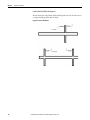
User Manual
Dynamix -1444 Series Monitoring System
Catalog Numbers 1444-DYN04-01RA, 1444-TSCX02-02RB, 1444-RELX00-04RB, and 1444-AOFX00-04RB
Important User Information
Read this document and the documents listed in the additional resources section about installation, configuration, and
operation of this equipment before you install, configure, operate, or maintain this product. Users are required to
familiarize themselves with installation and wiring instructions in addition to requirements of all applicable codes, laws,
and standards.
Activities including installation, adjustments, putting into service, use, assembly, disassembly, and maintenance are required
to be carried out by suitably trained personnel in accordance with applicable code of practice.
If this equipment is used in a manner not specified by the manufacturer, the protection provided by the equipment may be
impaired.
In no event will Rockwell Automation, Inc. be responsible or liable for indirect or consequential damages resulting from the
use or application of this equipment.
The examples and diagrams in this manual are included solely for illustrative purposes. Because of the many variables and
requirements associated with any particular installation, Rockwell Automation, Inc. cannot assume responsibility or
liability for actual use based on the examples and diagrams.
No patent liability is assumed by Rockwell Automation, Inc. with respect to use of information, circuits, equipment, or
software described in this manual.
Reproduction of the contents of this manual, in whole or in part, without written permission of Rockwell Automation,
Inc., is prohibited.
Throughout this manual, when necessary, we use notes to make you aware of safety considerations.
WARNING: Identifies information about practices or circumstances that can cause an explosion in a hazardous environment,
which may lead to personal injury or death, property damage, or economic loss.
ATTENTION: Identifies information about practices or circumstances that can lead to personal injury or death, property
damage, or economic loss. Attentions help you identify a hazard, avoid a hazard, and recognize the consequence.
IMPORTANT
Identifies information that is critical for successful application and understanding of the product.
Labels may also be on or inside the equipment to provide specific precautions.
SHOCK HAZARD: Labels may be on or inside the equipment, for example, a drive or motor, to alert people that dangerous
voltage may be present.
BURN HAZARD: Labels may be on or inside the equipment, for example, a drive or motor, to alert people that surfaces may
reach dangerous temperatures.
ARC FLASH HAZARD: Labels may be on or inside the equipment, for example, a motor control center, to alert people to
potential Arc Flash. Arc Flash will cause severe injury or death. Wear proper Personal Protective Equipment (PPE). Follow ALL
Regulatory requirements for safe work practices and for Personal Protective Equipment (PPE).
Allen-Bradley, Dynamix, Rockwell Software, and Rockwell Automation are trademarks of Rockwell Automation, Inc.
Trademarks not belonging to Rockwell Automation are property of their respective companies.
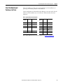
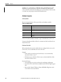
Summary of Changes
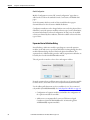
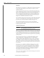
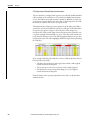
This manual contains new and updated information. Changes throughout this
revision are marked by change bars, as shown to the right of this paragraph.
New and Updated
Information
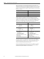
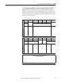
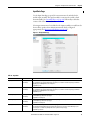
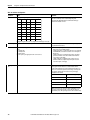
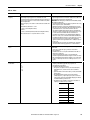
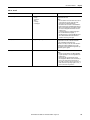
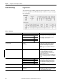
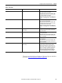
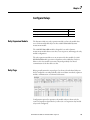
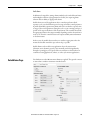
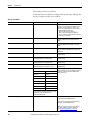
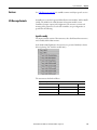
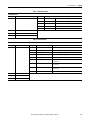
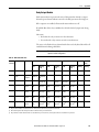
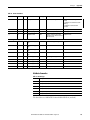
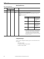
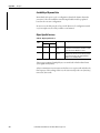
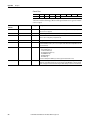
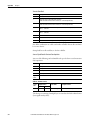
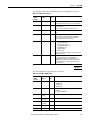
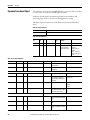
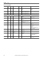
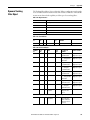
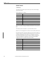
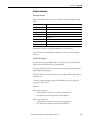
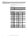
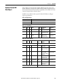
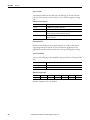
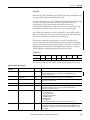
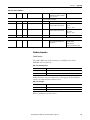
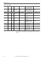
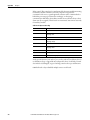
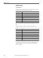
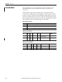
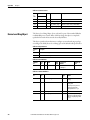
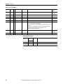
This table contains the major changes made to this revision.
Topic
Page
Ethernet Cable Information
15
Filters
109
Decimation Menu Selections
114
Tracking Filter Information
118
Normal Thrust Selection
135
Concluding Transient Events
177
Time Management
183
Transducer Fault Detection
189
Tachometer Signal Condition Input Fault Detection
189
Sampling Control
306
Rockwell Automation Publication 1444-UM001B-EN-P - August 2015
3
Summary of Changes
Notes:
4
Rockwell Automation Publication 1444-UM001B-EN-P - August 2015
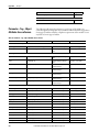
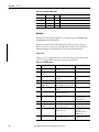
Table of Contents
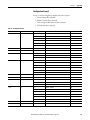
Table of Contents
Preface
Additional Resources . . . . . . . . . . . . . . . . . . . . . . . . . . . . . . . . . . . . . . . . . . . . . 13
Chapter 1
About the Dynamix 1444 Series
Dynamic Measurement Module
Applications . . . . . . . . . . . . . . . . . . . . . . . . . . . . . . . . . . . . . . . . . . . . . . . . . . . . .
Main Features. . . . . . . . . . . . . . . . . . . . . . . . . . . . . . . . . . . . . . . . . . . . . . . .
Product Description/System Overview . . . . . . . . . . . . . . . . . . . . . . . . . . . .
System Enclosure . . . . . . . . . . . . . . . . . . . . . . . . . . . . . . . . . . . . . . . . . . . . .
Cable, Connector, and Mounting Accessories. . . . . . . . . . . . . . . . . . .
System Components . . . . . . . . . . . . . . . . . . . . . . . . . . . . . . . . . . . . . . . . . . . . .
Network Connectivity and Considerations . . . . . . . . . . . . . . . . . . . . . . . .
15
16
17
19
19
21
22
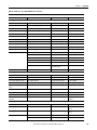
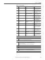
Chapter 2
Install the Dynamix 1444 Series
Monitoring System
Environment and Enclosure . . . . . . . . . . . . . . . . . . . . . . . . . . . . . . . . . . .
Prevent Electrostatic Discharge . . . . . . . . . . . . . . . . . . . . . . . . . . . . . . .
Electrical Safety Considerations . . . . . . . . . . . . . . . . . . . . . . . . . . . . . . .
North American Hazardous Location Approval . . . . . . . . . . . . . . . .
European/IECex Hazardous Location Approval . . . . . . . . . . . . . . . .
API-670 Compliance . . . . . . . . . . . . . . . . . . . . . . . . . . . . . . . . . . . . . . . . .
Removal or Insertion Under Power (RIUP) . . . . . . . . . . . . . . . . . . . .
Design Considerations . . . . . . . . . . . . . . . . . . . . . . . . . . . . . . . . . . . . . . . . . . .
Electro Magnetic Compatibility (EMC) Precautions . . . . . . . . . . . .
Wiring Categories and Routing. . . . . . . . . . . . . . . . . . . . . . . . . . . . . . . .
Temperature Considerations . . . . . . . . . . . . . . . . . . . . . . . . . . . . . . . . . .
Reliability Considerations. . . . . . . . . . . . . . . . . . . . . . . . . . . . . . . . . . . . .
System Space and Clearance Requirements . . . . . . . . . . . . . . . . . . . . .
Wiring Requirements . . . . . . . . . . . . . . . . . . . . . . . . . . . . . . . . . . . . . . . .
Module Power Supply Requirements. . . . . . . . . . . . . . . . . . . . . . . . . . .
Grounding Scheme . . . . . . . . . . . . . . . . . . . . . . . . . . . . . . . . . . . . . . . . . . .
Local Bus Connection (main/expansion) . . . . . . . . . . . . . . . . . . . . . . .
Using Local Bus Extension Cables . . . . . . . . . . . . . . . . . . . . . . . . . . . . .
Relay Contact Protection . . . . . . . . . . . . . . . . . . . . . . . . . . . . . . . . . . . . .
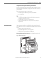
Installation Overview. . . . . . . . . . . . . . . . . . . . . . . . . . . . . . . . . . . . . . . . . . . . .
Mount the Terminal
Base Unit. . . . . . . . . . . . . . . . . . . . . . . . . . . . . . . . . . . . . . . . . . . . . . . . . . . . . . . .
Establish Bus Connections . . . . . . . . . . . . . . . . . . . . . . . . . . . . . . . . . . . . . . . .
Configure the Terminal Bases . . . . . . . . . . . . . . . . . . . . . . . . . . . . . . . . . . . . .
Configure the Main Terminal Base . . . . . . . . . . . . . . . . . . . . . . . . . . . .
Configure the Relay Terminal Base . . . . . . . . . . . . . . . . . . . . . . . . . . . .
Configure the 4…20 mA Terminal Base . . . . . . . . . . . . . . . . . . . . . . . .
Configure the Tacho Signal Conditioning Terminal Base. . . . . . . .
Install the Module. . . . . . . . . . . . . . . . . . . . . . . . . . . . . . . . . . . . . . . . . . . . . . . .
Wiring Overview. . . . . . . . . . . . . . . . . . . . . . . . . . . . . . . . . . . . . . . . . . . . . . . . .
Wiring the Main Module . . . . . . . . . . . . . . . . . . . . . . . . . . . . . . . . . . . . . . . . .
Upper Base Connector. . . . . . . . . . . . . . . . . . . . . . . . . . . . . . . . . . . . . . . .
Rockwell Automation Publication 1444-UM001B-EN-P - August 2015
26
26
26
27
29
29
30
30
30
31
33
35
36
37
38
39
40
41
42
43
45
46
47
47
48
48
49
49
50
51
52
5
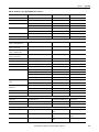
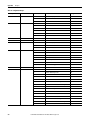
Table of Contents
Upper Module Connector . . . . . . . . . . . . . . . . . . . . . . . . . . . . . . . . . . . .
Lower Module Connector. . . . . . . . . . . . . . . . . . . . . . . . . . . . . . . . . . . . .
Lower Base Connector . . . . . . . . . . . . . . . . . . . . . . . . . . . . . . . . . . . . . . .
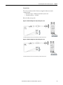
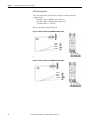
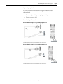
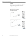
DYN Module Transducers . . . . . . . . . . . . . . . . . . . . . . . . . . . . . . . . . . . . . . . .
Proximity Probes . . . . . . . . . . . . . . . . . . . . . . . . . . . . . . . . . . . . . . . . . . . . .
2-wire Acceleration, Pressure, or Piezoelectric Velocity Sensors . . .
3-wire Acceleration Sensors or Other 3-wire Transducer Systems .
2-wire Self-Generating Velocity Sensors . . . . . . . . . . . . . . . . . . . . . . . .
3-wire Acceleration and Temperature Sensor . . . . . . . . . . . . . . . . . . .
Temperature Transmitter . . . . . . . . . . . . . . . . . . . . . . . . . . . . . . . . . . . . .
Tacho Signal from a Directly Connected Source. . . . . . . . . . . . . . . . .
EtherNet/IP Connector . . . . . . . . . . . . . . . . . . . . . . . . . . . . . . . . . . . . . . . . . .
Wiring Expansion Modules . . . . . . . . . . . . . . . . . . . . . . . . . . . . . . . . . . . . . . .
Relay Expansion Module . . . . . . . . . . . . . . . . . . . . . . . . . . . . . . . . . . . . . .
4…20 mA Expansion Module . . . . . . . . . . . . . . . . . . . . . . . . . . . . . . . . .
Tacho Signal Conditioning Expansion Module . . . . . . . . . . . . . . . . .
Start the Module and Perform a Self-test . . . . . . . . . . . . . . . . . . . . . . . . . . .
Expansion Module Startup Behavior . . . . . . . . . . . . . . . . . . . . . . . . . . .
58
60
62
63
63
65
67
67
68
69
70
72
73
74
76
78
85
86
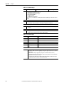
Chapter 3
Configure the 1444 Dynamic
Measurement Module
6
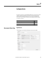
General Page . . . . . . . . . . . . . . . . . . . . . . . . . . . . . . . . . . . . . . . . . . . . . . . . . . . . . 88
Module Definition . . . . . . . . . . . . . . . . . . . . . . . . . . . . . . . . . . . . . . . . . . . . . . . 88
Module Definition Versus Module Configuration . . . . . . . . . . . . . . . 89
Expansion Device Definition Dialog . . . . . . . . . . . . . . . . . . . . . . . . . . . 90
Define Module Functionality Page . . . . . . . . . . . . . . . . . . . . . . . . . . . . . 92
Input Data Page . . . . . . . . . . . . . . . . . . . . . . . . . . . . . . . . . . . . . . . . . . . . . . 95
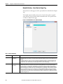
Module Definition - Select Data for Output Tag . . . . . . . . . . . . . . . 100
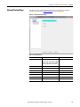
Internet Protocol Page . . . . . . . . . . . . . . . . . . . . . . . . . . . . . . . . . . . . . . . . . . . 101
Port Configuration Page . . . . . . . . . . . . . . . . . . . . . . . . . . . . . . . . . . . . . . . . . 102
Network Page . . . . . . . . . . . . . . . . . . . . . . . . . . . . . . . . . . . . . . . . . . . . . . . . . . . 103
Time Sync Page . . . . . . . . . . . . . . . . . . . . . . . . . . . . . . . . . . . . . . . . . . . . . . . . . 104
Hardware Configuration Page . . . . . . . . . . . . . . . . . . . . . . . . . . . . . . . . . . . . 105
Time Slot Multiplier Page . . . . . . . . . . . . . . . . . . . . . . . . . . . . . . . . . . . . . . . . 112
Speed Page . . . . . . . . . . . . . . . . . . . . . . . . . . . . . . . . . . . . . . . . . . . . . . . . . . . . . . 115
Rockwell Automation Publication 1444-UM001B-EN-P - August 2015
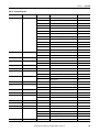
Table of Contents
Chapter 4
Measurement Definition
Filters . . . . . . . . . . . . . . . . . . . . . . . . . . . . . . . . . . . . . . . . . . . . . . . . . . . . . . . . . .
Overall . . . . . . . . . . . . . . . . . . . . . . . . . . . . . . . . . . . . . . . . . . . . . . . . . . . . . . . . .
Tracking Filters . . . . . . . . . . . . . . . . . . . . . . . . . . . . . . . . . . . . . . . . . . . . . . . . .
Aero Derivative Measurements . . . . . . . . . . . . . . . . . . . . . . . . . . . . . . .
Not-1X Measurement . . . . . . . . . . . . . . . . . . . . . . . . . . . . . . . . . . . . . . .
Order Phase. . . . . . . . . . . . . . . . . . . . . . . . . . . . . . . . . . . . . . . . . . . . . . . . .
Influence of Sample Rate and Tracking Filter Definition Settings
FFT. . . . . . . . . . . . . . . . . . . . . . . . . . . . . . . . . . . . . . . . . . . . . . . . . . . . . . . . . . . .
gSE . . . . . . . . . . . . . . . . . . . . . . . . . . . . . . . . . . . . . . . . . . . . . . . . . . . . . . . . . . . .
Bands . . . . . . . . . . . . . . . . . . . . . . . . . . . . . . . . . . . . . . . . . . . . . . . . . . . . . . . . . .
DC . . . . . . . . . . . . . . . . . . . . . . . . . . . . . . . . . . . . . . . . . . . . . . . . . . . . . . . . . . . .
Demand. . . . . . . . . . . . . . . . . . . . . . . . . . . . . . . . . . . . . . . . . . . . . . . . . . . . . . . .
118
126
128
129
129
130
130
134
137
139
143
155
Chapter 5
Configure the Tachometer Expansion Tachometer Expansion Module . . . . . . . . . . . . . . . . . . . . . . . . . . . . . . . . . . 157
Tachometer Page. . . . . . . . . . . . . . . . . . . . . . . . . . . . . . . . . . . . . . . . . . . . . . . . 158
Module
Page Overview . . . . . . . . . . . . . . . . . . . . . . . . . . . . . . . . . . . . . . . . . . . . . . 158
Chapter 6
Configure Analog Outputs
Analog Expansion Module . . . . . . . . . . . . . . . . . . . . . . . . . . . . . . . . . . . . . . . 161
Output Configuration Page . . . . . . . . . . . . . . . . . . . . . . . . . . . . . . . . . . . . . . 162
Page Overview . . . . . . . . . . . . . . . . . . . . . . . . . . . . . . . . . . . . . . . . . . . . . . 162
Chapter 7
Configure Relays
Relay Expansion Module . . . . . . . . . . . . . . . . . . . . . . . . . . . . . . . . . . . . . . . .
Relay Page . . . . . . . . . . . . . . . . . . . . . . . . . . . . . . . . . . . . . . . . . . . . . . . . . . . . . .
Relay Management Overview. . . . . . . . . . . . . . . . . . . . . . . . . . . . . . . . .
Alarm Output . . . . . . . . . . . . . . . . . . . . . . . . . . . . . . . . . . . . . . . . . . . . . .
Main Module Fault Output . . . . . . . . . . . . . . . . . . . . . . . . . . . . . . . . . .
Expansion Module Fault Output . . . . . . . . . . . . . . . . . . . . . . . . . . . . .
Relay Drive Testing. . . . . . . . . . . . . . . . . . . . . . . . . . . . . . . . . . . . . . . . . .
Double-pole, Double-throw (DPDT) Relay Solutions . . . . . . . . . .
Notes:. . . . . . . . . . . . . . . . . . . . . . . . . . . . . . . . . . . . . . . . . . . . . . . . . . . . . . . . . .
165
165
167
167
168
169
170
171
172
Chapter 7
Configure Alarms
Measurement Alarms Page . . . . . . . . . . . . . . . . . . . . . . . . . . . . . . . . . . . . . . .
Page Overview . . . . . . . . . . . . . . . . . . . . . . . . . . . . . . . . . . . . . . . . . . . . . .
Alarm Measurement Definition . . . . . . . . . . . . . . . . . . . . . . . . . . . . . .
Voted Alarms Page . . . . . . . . . . . . . . . . . . . . . . . . . . . . . . . . . . . . . . . . . . . . . .
Relays . . . . . . . . . . . . . . . . . . . . . . . . . . . . . . . . . . . . . . . . . . . . . . . . . . . . . . . . . .
Rockwell Automation Publication 1444-UM001B-EN-P - August 2015
173
173
177
179
186
7
Table of Contents
Chapter 8
Trend and Transient Capture
Trend Page . . . . . . . . . . . . . . . . . . . . . . . . . . . . . . . . . . . . . . . . . . . . . . . . . . . . .
Page Overview. . . . . . . . . . . . . . . . . . . . . . . . . . . . . . . . . . . . . . . . . . . . . . .
Discrete Data Buffers . . . . . . . . . . . . . . . . . . . . . . . . . . . . . . . . . . . . . . . .
Trend Buffer . . . . . . . . . . . . . . . . . . . . . . . . . . . . . . . . . . . . . . . . . . . . . . . .
Dynamic Buffer . . . . . . . . . . . . . . . . . . . . . . . . . . . . . . . . . . . . . . . . . . . . .
Alarm Buffer . . . . . . . . . . . . . . . . . . . . . . . . . . . . . . . . . . . . . . . . . . . . . . . .
Transient Capture Page . . . . . . . . . . . . . . . . . . . . . . . . . . . . . . . . . . . . . . . . . .
Page Overview . . . . . . . . . . . . . . . . . . . . . . . . . . . . . . . . . . . . . . . . . . . . . .
Buffers. . . . . . . . . . . . . . . . . . . . . . . . . . . . . . . . . . . . . . . . . . . . . . . . . . . . . .
Overflow. . . . . . . . . . . . . . . . . . . . . . . . . . . . . . . . . . . . . . . . . . . . . . . . . . . .
Initiating a Transient Event . . . . . . . . . . . . . . . . . . . . . . . . . . . . . . . . . .
Dynamic Data. . . . . . . . . . . . . . . . . . . . . . . . . . . . . . . . . . . . . . . . . . . . . . .
Sampling During a Transient Event . . . . . . . . . . . . . . . . . . . . . . . . . . .
Concluding a Transient Event . . . . . . . . . . . . . . . . . . . . . . . . . . . . . . . .
Latching . . . . . . . . . . . . . . . . . . . . . . . . . . . . . . . . . . . . . . . . . . . . . . . . . . . .
187
187
188
189
189
190
192
192
193
193
193
194
194
195
195
Chapter 9
Operate the Module
8
Resetting the Module . . . . . . . . . . . . . . . . . . . . . . . . . . . . . . . . . . . . . . . . . . . . 197
Supported Reset Types . . . . . . . . . . . . . . . . . . . . . . . . . . . . . . . . . . . . . . . 197
Reset Procedures. . . . . . . . . . . . . . . . . . . . . . . . . . . . . . . . . . . . . . . . . . . . . 199
Updating Module Firmware. . . . . . . . . . . . . . . . . . . . . . . . . . . . . . . . . . . . . . 203
Managing GET and SET Service Access . . . . . . . . . . . . . . . . . . . . . . . . . . . 204
SET . . . . . . . . . . . . . . . . . . . . . . . . . . . . . . . . . . . . . . . . . . . . . . . . . . . . . . . . 204
GET Services . . . . . . . . . . . . . . . . . . . . . . . . . . . . . . . . . . . . . . . . . . . . . . . . 205
Managing Nonvolatile Memory Configuration . . . . . . . . . . . . . . . . . . . . 205
Saving a Configuration to Nonvolatile Memory . . . . . . . . . . . . . . . . 205
Deleting a Saved Configuration from Nonvolatile Memory . . . . . 206
Setting The IP Address . . . . . . . . . . . . . . . . . . . . . . . . . . . . . . . . . . . . . . . . . . 207
Static IP Configuration . . . . . . . . . . . . . . . . . . . . . . . . . . . . . . . . . . . . . . 207
Automatic IP Configuration. . . . . . . . . . . . . . . . . . . . . . . . . . . . . . . . . . 207
Time Management . . . . . . . . . . . . . . . . . . . . . . . . . . . . . . . . . . . . . . . . . . . . . . 207
Module Inputs . . . . . . . . . . . . . . . . . . . . . . . . . . . . . . . . . . . . . . . . . . . . . . . . . . 209
1444-DYN04-01RA Dynamic Measurement Module . . . . . . . . . . 209
Channel Inputs . . . . . . . . . . . . . . . . . . . . . . . . . . . . . . . . . . . . . . . . . . . . . 209
Transducer Fault Detection . . . . . . . . . . . . . . . . . . . . . . . . . . . . . . . . . . 209
1444-TSCX02-02RB Tachometer Signal Conditioner Expansion
Module . . . . . . . . . . . . . . . . . . . . . . . . . . . . . . . . . . . . . . . . . . . . . . . . . . . . . 212
1444-RELX00-04RB Relay Expansion Module . . . . . . . . . . . . . . . . 212
1444-AOFX00-04RB 4…20 mA Output Expansion Module . . . . 212
Module Outputs . . . . . . . . . . . . . . . . . . . . . . . . . . . . . . . . . . . . . . . . . . . . . . . . 213
1444-DYN04-01RA Dynamic Measurement Module . . . . . . . . . . 213
1444-TSCX02-02RB Tachometer Signal Conditioner Expansion
Module . . . . . . . . . . . . . . . . . . . . . . . . . . . . . . . . . . . . . . . . . . . . . . . . . . . . . 213
1444-RELX00-04RB Relay Expansion Module . . . . . . . . . . . . . . . . 214
1444-AOFX00-04RB 4…20 mA Output Expansion Module . . . . 214
Rockwell Automation Publication 1444-UM001B-EN-P - August 2015
Table of Contents
Services . . . . . . . . . . . . . . . . . . . . . . . . . . . . . . . . . . . . . . . . . . . . . . . . . . . . . . . .
I/O Message Formats. . . . . . . . . . . . . . . . . . . . . . . . . . . . . . . . . . . . . . . . . . . .
Input Assembly . . . . . . . . . . . . . . . . . . . . . . . . . . . . . . . . . . . . . . . . . . . . .
Output Assembly. . . . . . . . . . . . . . . . . . . . . . . . . . . . . . . . . . . . . . . . . . . .
Calibration . . . . . . . . . . . . . . . . . . . . . . . . . . . . . . . . . . . . . . . . . . . . . . . . . . . . .
215
215
215
233
234
Appendix A
Status
Status Indicators . . . . . . . . . . . . . . . . . . . . . . . . . . . . . . . . . . . . . . . . . . . . . . . .
Main Module Status Indicators . . . . . . . . . . . . . . . . . . . . . . . . . . . . . . .
Ethernet Port Status Indicators . . . . . . . . . . . . . . . . . . . . . . . . . . . . . . .
Expansion Module Status Indicators . . . . . . . . . . . . . . . . . . . . . . . . . .
Tacho (TSC) Module . . . . . . . . . . . . . . . . . . . . . . . . . . . . . . . . . . . . . . .
4…20 mA Output Status Indicators . . . . . . . . . . . . . . . . . . . . . . . . . . .
Relay Output Module . . . . . . . . . . . . . . . . . . . . . . . . . . . . . . . . . . . . . . .
235
235
237
237
238
240
241
Appendix B
CIP Objects
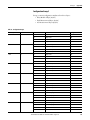
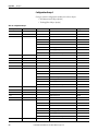
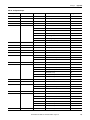
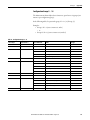
Parameter – Tag – Object Attribute Cross-reference . . . . . . . . . . . . . . .
Engineering Units (ENGUNITS data type) . . . . . . . . . . . . . . . . . . .
Dynamix Configuration Manager Object . . . . . . . . . . . . . . . . . . . . . . . . .
............................................................
............................................................
Attribute Semantics . . . . . . . . . . . . . . . . . . . . . . . . . . . . . . . . . . . . . . . . .
Object Specific Services . . . . . . . . . . . . . . . . . . . . . . . . . . . . . . . . . . . . . .
Configuration Group 1 . . . . . . . . . . . . . . . . . . . . . . . . . . . . . . . . . . . . . .
Configuration Group 3 . . . . . . . . . . . . . . . . . . . . . . . . . . . . . . . . . . . . . .
Configuration Group 4 . . . . . . . . . . . . . . . . . . . . . . . . . . . . . . . . . . . . . .
Configuration Groups 5…16 . . . . . . . . . . . . . . . . . . . . . . . . . . . . . . . . .
Configuration Group 17 . . . . . . . . . . . . . . . . . . . . . . . . . . . . . . . . . . . . .
Configuration Group 18 . . . . . . . . . . . . . . . . . . . . . . . . . . . . . . . . . . . . .
Configuration Group 19 . . . . . . . . . . . . . . . . . . . . . . . . . . . . . . . . . . . . .
Configuration Groups 20 and 21 . . . . . . . . . . . . . . . . . . . . . . . . . . . . .
Configuration Group 22 . . . . . . . . . . . . . . . . . . . . . . . . . . . . . . . . . . . . .
Configuration Group 23 . . . . . . . . . . . . . . . . . . . . . . . . . . . . . . . . . . . . .
Configuration Group 24 . . . . . . . . . . . . . . . . . . . . . . . . . . . . . . . . . . . . .
Configuration Group 25 . . . . . . . . . . . . . . . . . . . . . . . . . . . . . . . . . . . . .
Configuration Group 26 . . . . . . . . . . . . . . . . . . . . . . . . . . . . . . . . . . . . .
Configuration Group 27 . . . . . . . . . . . . . . . . . . . . . . . . . . . . . . . . . . . . .
Configuration Group 28 . . . . . . . . . . . . . . . . . . . . . . . . . . . . . . . . . . . . .
Configuration Group 29 . . . . . . . . . . . . . . . . . . . . . . . . . . . . . . . . . . . . .
Dynamix Data Manager Object . . . . . . . . . . . . . . . . . . . . . . . . . . . . . . . . . .
Attribute Semantics . . . . . . . . . . . . . . . . . . . . . . . . . . . . . . . . . . . . . . . . .
Availability of Dynamic Data. . . . . . . . . . . . . . . . . . . . . . . . . . . . . . . . .
Object Specific Services . . . . . . . . . . . . . . . . . . . . . . . . . . . . . . . . . . . . . .
Behavior . . . . . . . . . . . . . . . . . . . . . . . . . . . . . . . . . . . . . . . . . . . . . . . . . . . .
Dynamix Transient Data Manager Object. . . . . . . . . . . . . . . . . . . . . . . . .
Attribute Semantics . . . . . . . . . . . . . . . . . . . . . . . . . . . . . . . . . . . . . . . . .
Rockwell Automation Publication 1444-UM001B-EN-P - August 2015
244
251
252
252
253
253
258
258
265
268
271
273
277
281
290
294
295
295
296
296
297
297
298
299
301
304
304
309
311
313
9
Table of Contents
Dynamix Event Log Object . . . . . . . . . . . . . . . . . . . . . . . . . . . . . . . . . . . . . .
Behavior . . . . . . . . . . . . . . . . . . . . . . . . . . . . . . . . . . . . . . . . . . . . . . . . . . . .
Dynamix Transducer Object . . . . . . . . . . . . . . . . . . . . . . . . . . . . . . . . . . . . .
Attribute Semantics. . . . . . . . . . . . . . . . . . . . . . . . . . . . . . . . . . . . . . . . . .
Dynamix Channel
Setup Object . . . . . . . . . . . . . . . . . . . . . . . . . . . . . . . . . . . . . . . . . . . . . . . . . . . .
Attribute Semantics. . . . . . . . . . . . . . . . . . . . . . . . . . . . . . . . . . . . . . . . . .
Dynamix AC
Measurement Object . . . . . . . . . . . . . . . . . . . . . . . . . . . . . . . . . . . . . . . . . . . .
Attribute Semantics. . . . . . . . . . . . . . . . . . . . . . . . . . . . . . . . . . . . . . . . . .
Dynamix DC
Measurement Object . . . . . . . . . . . . . . . . . . . . . . . . . . . . . . . . . . . . . . . . . . . .
Attribute Semantics. . . . . . . . . . . . . . . . . . . . . . . . . . . . . . . . . . . . . . . . . .
Dynamix Dual
Measurement Object . . . . . . . . . . . . . . . . . . . . . . . . . . . . . . . . . . . . . . . . . . . .
Attribute Semantics. . . . . . . . . . . . . . . . . . . . . . . . . . . . . . . . . . . . . . . . . .
Behavior . . . . . . . . . . . . . . . . . . . . . . . . . . . . . . . . . . . . . . . . . . . . . . . . . . . .
Dynamix Tracking
Filter Object . . . . . . . . . . . . . . . . . . . . . . . . . . . . . . . . . . . . . . . . . . . . . . . . . . . .
Attribute Semantics. . . . . . . . . . . . . . . . . . . . . . . . . . . . . . . . . . . . . . . . . .
Behavior . . . . . . . . . . . . . . . . . . . . . . . . . . . . . . . . . . . . . . . . . . . . . . . . . . . .
Dynamix TSC Module Object. . . . . . . . . . . . . . . . . . . . . . . . . . . . . . . . . . . .
Attribute Semantics. . . . . . . . . . . . . . . . . . . . . . . . . . . . . . . . . . . . . . . . . .
Dynamix Tacho and Speed Measurement Object . . . . . . . . . . . . . . . . . .
Attribute Semantics. . . . . . . . . . . . . . . . . . . . . . . . . . . . . . . . . . . . . . . . . .
Behavior . . . . . . . . . . . . . . . . . . . . . . . . . . . . . . . . . . . . . . . . . . . . . . . . . . . .
Dynamix Measurement Alarm Object. . . . . . . . . . . . . . . . . . . . . . . . . . . . .
Attribute Semantics. . . . . . . . . . . . . . . . . . . . . . . . . . . . . . . . . . . . . . . . . .
Behavior . . . . . . . . . . . . . . . . . . . . . . . . . . . . . . . . . . . . . . . . . . . . . . . . . . . .
Dynamix Voted Alarm Object. . . . . . . . . . . . . . . . . . . . . . . . . . . . . . . . . . . .
Class Attribute Semantics . . . . . . . . . . . . . . . . . . . . . . . . . . . . . . . . . . . .
Attribute Semantics. . . . . . . . . . . . . . . . . . . . . . . . . . . . . . . . . . . . . . . . . .
Behavior . . . . . . . . . . . . . . . . . . . . . . . . . . . . . . . . . . . . . . . . . . . . . . . . . . . .
Dynamix Normal CM
Data Object. . . . . . . . . . . . . . . . . . . . . . . . . . . . . . . . . . . . . . . . . . . . . . . . . . . . .
Attribute Semantics. . . . . . . . . . . . . . . . . . . . . . . . . . . . . . . . . . . . . . . . . .
Behavior . . . . . . . . . . . . . . . . . . . . . . . . . . . . . . . . . . . . . . . . . . . . . . . . . . . .
Dynamix FFT Band Object . . . . . . . . . . . . . . . . . . . . . . . . . . . . . . . . . . . . . .
Attribute Semantics. . . . . . . . . . . . . . . . . . . . . . . . . . . . . . . . . . . . . . . . . .
Dynamix Advanced CM
Data Object. . . . . . . . . . . . . . . . . . . . . . . . . . . . . . . . . . . . . . . . . . . . . . . . . . . . .
Attribute Semantics. . . . . . . . . . . . . . . . . . . . . . . . . . . . . . . . . . . . . . . . . .
Behavior . . . . . . . . . . . . . . . . . . . . . . . . . . . . . . . . . . . . . . . . . . . . . . . . . . . .
Dynamix MUX Object . . . . . . . . . . . . . . . . . . . . . . . . . . . . . . . . . . . . . . . . . .
Dynamix MUX Object. . . . . . . . . . . . . . . . . . . . . . . . . . . . . . . . . . . . . . .
Dynamix Relay
Module Object . . . . . . . . . . . . . . . . . . . . . . . . . . . . . . . . . . . . . . . . . . . . . . . . . .
10
Rockwell Automation Publication 1444-UM001B-EN-P - August 2015
319
324
328
329
331
333
335
337
339
340
343
344
345
347
349
351
352
354
357
359
360
361
365
369
370
371
373
378
379
380
390
392
393
394
395
406
408
409
412
Table of Contents
Attribute Semantics . . . . . . . . . . . . . . . . . . . . . . . . . . . . . . . . . . . . . . . . .
Dynamix Current Output Module Object . . . . . . . . . . . . . . . . . . . . . . . .
Attribute Semantics . . . . . . . . . . . . . . . . . . . . . . . . . . . . . . . . . . . . . . . . .
Dynamix Module Control Object . . . . . . . . . . . . . . . . . . . . . . . . . . . . . . . .
Attribute Semantics . . . . . . . . . . . . . . . . . . . . . . . . . . . . . . . . . . . . . . . . .
Identity Object . . . . . . . . . . . . . . . . . . . . . . . . . . . . . . . . . . . . . . . . . . . . . . . . .
Class Attributes . . . . . . . . . . . . . . . . . . . . . . . . . . . . . . . . . . . . . . . . . . . . .
Attribute Semantics . . . . . . . . . . . . . . . . . . . . . . . . . . . . . . . . . . . . . . . . .
Message Router Object . . . . . . . . . . . . . . . . . . . . . . . . . . . . . . . . . . . . . . . . . .
Assembly Object . . . . . . . . . . . . . . . . . . . . . . . . . . . . . . . . . . . . . . . . . . . . . . . .
Attribute Semantics . . . . . . . . . . . . . . . . . . . . . . . . . . . . . . . . . . . . . . . . .
File Object . . . . . . . . . . . . . . . . . . . . . . . . . . . . . . . . . . . . . . . . . . . . . . . . . . . . .
Time Sync Object . . . . . . . . . . . . . . . . . . . . . . . . . . . . . . . . . . . . . . . . . . . . . . .
Device Level Ring Object . . . . . . . . . . . . . . . . . . . . . . . . . . . . . . . . . . . . . . . .
Quality of Service Object . . . . . . . . . . . . . . . . . . . . . . . . . . . . . . . . . . . . . . . .
TCP/IP Interface Object . . . . . . . . . . . . . . . . . . . . . . . . . . . . . . . . . . . . . . . .
Ethernet Link Object. . . . . . . . . . . . . . . . . . . . . . . . . . . . . . . . . . . . . . . . . . . .
Nonvolatile Storage Object . . . . . . . . . . . . . . . . . . . . . . . . . . . . . . . . . . . . . .
Common Codes and Structures . . . . . . . . . . . . . . . . . . . . . . . . . . . . . . . . . .
Engineering Units . . . . . . . . . . . . . . . . . . . . . . . . . . . . . . . . . . . . . . . . . . .
Rockwell Automation Publication 1444-UM001B-EN-P - August 2015
415
420
422
423
427
433
433
434
434
435
436
436
438
441
442
443
444
446
447
449
11
Table of Contents
Notes:
12
Rockwell Automation Publication 1444-UM001B-EN-P - August 2015
Preface
This manual describes the Dynamix™ 1444 Series dynamic measurement module.
The information in the following chapters discusses installation, configuration,
and operation of the module.
The module measures dynamic inputs such as vibration, pressure, and static
inputs such as thrust, eccentricity, and rod drop. The 1444-DYN04-01RA
module is designed specifically for integration with Allen-Bradley Logix
controllers connected across an industrial Ethernet network.
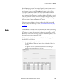
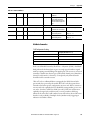
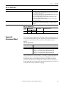
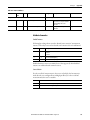
Additional Resources
These documents contain additional information concerning related products
from Rockwell Automation.
Resource
Description
Industrial Automation Wiring and Grounding Guidelines,
publication 1770-4.1
Provides general guidelines for installing a Rockwell
Automation industrial system.
Product Certifications Website, http://www.ab.com
Provides declarations of conformity, certificates, and
other certification details.
Dynamix 1444 Series Monitoring System Specifications
Technical Data, publication 1444-TD001
Provides system specifications for the Dynamix 1444
Series Monitoring System.
You can view or download publications at
http://www.rockwellautomation.com/literature/. To order paper copies of
technical documentation, contact your local Allen-Bradley Distributor or
Rockwell Automation sales representative.
Rockwell Automation Publication 1444-UM001B-EN-P - August 2015
13
Preface
Notes:
14
Rockwell Automation Publication 1444-UM001B-EN-P - August 2015
Chapter
1
About the Dynamix 1444 Series Dynamic
Measurement Module
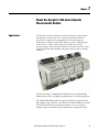
Applications
The Dynamix™ 1444 Series dynamic measurement module is a four-channel,
general-purpose monitor that can serve almost any industrial machinery
protection or condition monitoring application. The module supports
measurements of dynamic inputs such as vibration, pressure, and static inputs
such as thrust, eccentricity, and rod drop. The module can be used for
monitoring shaft, casing, and pedestal vibration, shaft and rod position, casing
expansion and other critical dynamic and position measurements on rotating
machinery.
To achieve this degree of adaptability the module marries an extraordinarily
flexible firmware and an incredibly powerful multi-processor hardware platform.
The 1444-DYN04-01RA module is designed specifically for integration with
Allen-Bradley Logix controllers connected across an industrial Ethernet network.
This makes the 1444 Series unequaled in its ability to serve as a synergetic
member of larger total facility control and information management systems.
Rockwell Automation Publication 1444-UM001B-EN-P - August 2015
15
Chapter 1
About the Dynamix 1444 Series Dynamic Measurement Module
The 1444 Series includes the main module (1444-DYN04-01RA) plus three
optional expansion modules. The expansion modules, a tachometer signal
conditioner, a relay module and an analog output module, are configured and
managed from their host “main” module. Therefore configuration of these
capabilities is included in the AOP for the main dynamic measurement module.
The main module also manages errors that are associated with any expansion
module. The behavior of the expansion modules themselves on the failure of its
host main module, or loss of communication to the main module, can also be
defined.
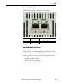
The module supports the EtherNet/IP communication protocol and includes
two RJ45 Ethernet ports. These ports can be applied as either standard Ethernet
connections, where modules are daisy chained one to the next, or implemented
by using Device Level Ring (DLR).
Main Features
The DYN module offers the following major features:
• Distributed vibration module with direct EtherNet/IP network
connectivity
• Multifunction: configurable for eddy current probes, accelerometers,
velocimeters, and all common dynamic measurement sensors that output
voltages from -24V to +24V DC.
• Four measurement channels and two tacho (TTL) circuits
• Transducer supply configurable per channel, as one of:
– Constant Current Mode: +24 V/4 mA
– Constant Voltage Mode: +24 V/25 mA
– Constant Voltage Mode: -24 V/25 mA
• Buffered signal outputs (output current limited)
• Measurement bandwidth up to 18 kHz (4-channels), 40 kHz (2-channels)
• Digital filtering and signal analysis, including integration
• Supports Spike Energy (gSE) measurements
• Implements HP and LP filters (4-pole Butterworth), with infinitely
variable -3 dB points
• Sophisticated and flexible alarm logic
• Protection alarm checking, typically every 40 ms
• Relay output (SPDT) rated for 30V DC and 250V AC
• FFT analysis capability
16
Rockwell Automation Publication 1444-UM001B-EN-P - August 2015
About the Dynamix 1444 Series Dynamic Measurement Module
Chapter 1
• Configurable for specialist measurements such as:
– Rod drop
– Ramp or complementary differential expansion
– Eccentricity
– Absolute shaft vibration
• Over 20 different measurement parameters per measurement channel,
such as RMS, peak, FFT band RMS, order magnitudes, phase, and speed
• Onboard storage of:
– Trend data (discrete and dynamic data records)
– Alarm/Event data (discrete and dynamic data records)
– Transient data (discrete and dynamic data records)
• Expansion modules available to enhance system capabilities:
– 4-channel Relay output module (up to three per each DYN module)
– 2-channel Tacho Signal Conditioning module
– 4-channel 4…20 mA output module
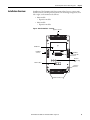
Product Description/System
Overview
The Dynamix series consists of just six core part numbers and various accessories
for connectors and cables.
A minimum Dynamix 1444 Series monitoring system consists of the following:
• One DYN module, which is comprised of a terminal base, a module, and
either spring or screw clamp removable plug connectors for both the
module and terminal base.
• Appropriate enclosure
• Sensors
• Power supply unit
Expansion modules provide enhanced or optional I/O capabilities that are
application-dependent:
• 4-channel relay output modules (RELX)
• 4-channel 4…20 mA output module (AOFX)
• 2-channel Tacho Signal Conditioning module (TSCX)
Up to three RELX modules and one each AOFX and TSCX module can be
connected to one DYN module. Interconnections between a DYN module and
its Expansion module (and to extend the tacho bus from one such group to
further DYN modules) are by ribbon cable assembly:
Rockwell Automation Publication 1444-UM001B-EN-P - August 2015
17
Chapter 1
About the Dynamix 1444 Series Dynamic Measurement Module
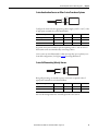
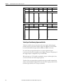
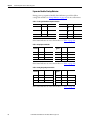
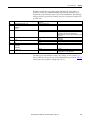
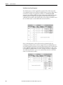
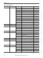
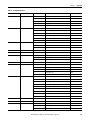
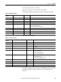
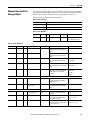
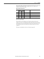
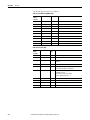
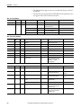
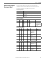
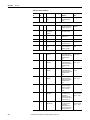
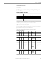
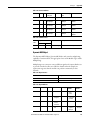
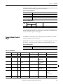
The following parts listings conform to this hierarchical structure:
• Assembly level (of module and base excluding connectors)
– Connector level (choice of screw or spring clamp type)
– Component level (module or base as spare/replacement item)
Table 1 - 1444 Series Catalog Numbers
Type
Module
Catalog Number
Measurement modules
Dynamic measurement module
1444-DYN04-01RA
Speed modules
Tachometer signal conditioner expansion module
1444-TSCX02-02RB
Relay modules
Relay expansion module
1444-RELX00-04RB
Analog output modules
4…20 mA expansion module
1444-AOFX00-04RB
Terminal bases
Dynamic measurement module terminal base
1444-TB-A
Expansion module terminal base
1444-TB-B
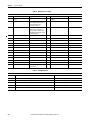
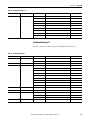
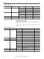
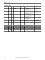
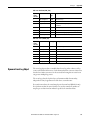
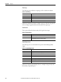
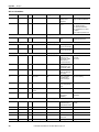
Table 2 - Removable Plug Connector Sets
Module
Spring Connector
Screw Connector
1444-DYN04-01RA
1444-DYN-RPC-SPR-01
1444-DYN-RPC-SCW-01
1444-TSCX02-02RB
1444-TSC-RPC-SPR-01
1444-TSC-RPC-SCW-01
1444-RELX00-04RB
1444-REL-RPC-SPR-01
1444-REL-RPC-SCW-01
1444-AOFX00-04RB
1444-AOF-RPC-SPR-01
1444-AOF-RPC-SCW-01
Terminal Base
Spring Connector
Screw Connector
1444-TB-A
1444-TBA-RPC-SPR-01
1444-TBA-RPC-SCW-01
1444-TB-B
1444-TBB-RPC-SPR-01
1444-TBB-RPC-SCW-01
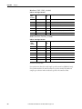
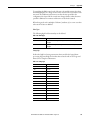
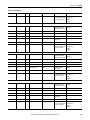
Table 3 - 1444 Series Interconnect Cable Accessories
Catalog Number
Description
1444-LBIC-04
Local bus interconnect cable (qty 4)
1444-LBXC-0M3-01
Local bus extender cable, 0.3m (11.8 in.)
1444-LBXC-1M0-01
Local bus extender cable, 1.0 m (39.4 in.)
Each main and expansion module terminal base includes one standard ribbon
cable connector. This connector is sufficient to interconnect all main and
expansion modules in a system.
18
Rockwell Automation Publication 1444-UM001B-EN-P - August 2015
About the Dynamix 1444 Series Dynamic Measurement Module
Chapter 1
System Enclosure
An IP54 weatherproof enclosure is recommended for general applications and
required for use in hazardous area locations.
Use of a metal enclosure is recommended to enhance EMC and thermal system
performance.
Cable, Connector, and Mounting Accessories
Local Bus (module to module, interconnect cables)
1444 series modules are connected through a local bus that is implemented by the
use of a simple ribbon cable that spans one module to the next. The packaging for
each terminal base includes a cable that is designed to the exact length necessary
to connect two adjacent modules.
The extended interconnect cables provide a means to extend the local bus
between terminal bases on different DIN rails or in different areas of a cabinet.
Extended interconnect cables are rated to 300V and from -40…105 °C
(-40…221 °F).
The accessory list also includes a package of four standard length interconnect
cables (catalog number 1444-LBIC-04). These cables can be used to replace the
cable included with each terminal base.
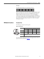
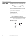
Ethernet Cables
The 1444 products are designed to operate in harsh industrial environments and
possibly close to electrically noisy or high-voltage devices and wiring. You must
consider the environment, over the entire run of the cable, when determining an
appropriate cable for the application.
Rockwell Automation Publication 1444-UM001B-EN-P - August 2015
19
Chapter 1
About the Dynamix 1444 Series Dynamic Measurement Module
Channel Class and Category
Dynamix 1444 Series monitors can be used with shielded or un-shielded
Ethernet media. Shielded cable or entirely enclosing the cable within a shielded
environment, such as an electrical enclosure or metal conduit, must be considered
for cables longer than 3 m (9.8 ft.) to help ensure EMC compliance.
See Rockwell Automation documents 1585-BR001B-EN-P Industrial Ethernet
Media and ENET-RM002C-EN-P Ethernet design considerations for
information on selecting appropriate Ethernet media for your application.
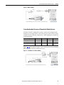
Recommended Cables
Only straight connectors are recommended for use with the 1444 products.
Verify that the temperature rating of the selected cable is appropriate to the
environment in which the 1444 product is installed, up to and including 70 °C
(158 °F).
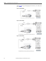
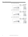
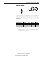
Compatible Sensors
The following types of sensors that can be connected to a DYN module:
• 2-wire piezoelectric acceleration sensor
• 3-wire piezoelectric acceleration sensor with temperature sensing
• 2-wire piezoelectric dynamic pressure sensor
• 2-wire piezoelectric velocity sensors
• 2-wire self-generating velocity sensors
• 3-wire piezoelectric acceleration sensor
• 3-wire eddy current probe (ECP) systems
• Buffered voltage outputs
• Process proportional voltage signals (such as temperature, pressure, and
flow)
There is a transducer supply available for each channel that can be independently
enabled and configured negative or positive operation (25 mA at 24V) or as a
positive constant current source at 4 mA, 24V. The transducer power supply
output is made available at a separate terminal so that, by appropriate wiring, it is
possible to connect either two or three wire transducers.
20
Rockwell Automation Publication 1444-UM001B-EN-P - August 2015
About the Dynamix 1444 Series Dynamic Measurement Module
System Components
Chapter 1
The Dynamix 1444 series is a machinery protection system comprising at least
one DYN module that has four channels for vibration or related measurements,
two TTL speed inputs, and one relay output.
Expansion modules then provide more output and input capacity that cannot be
accommodated within that DYN module. The use of expansion modules is
entirely optional and dependent on the specific application requirements.
For critical applications, the DYN modules support EtherNet/IP
communication, including Device Level Ring (DLR) configurations and accept
wide ranging (18...32 V, 24V nominal) redundant power inputs.
When expansion modules are used, the following apply:
• Any expansion modules are fitted to the right of their host DYN module.
• Expansion modules provide more relays, 4…20 mA outputs, and
tachometer signal conditioning facilities.
• A local bus (ribbon cable) connects the main to its expansion modules,
providing:
– Current limited (fuse protected) power for the expansion modules
– Local communication (main with expansion)
– A dual tacho bus that distributes the TSCX modules TTL outputs
• The tacho bus can be extended to other DYN modules by fitting a bus
cable from the end of the expansion module group or from the left side of
the associated DYN module, as required.
The expansion relay module can initiate an alarm or placing the machine in a safe
state if it detects the DYN module is no longer responding correctly or in a timely
manner.
Rockwell Automation Publication 1444-UM001B-EN-P - August 2015
21
Chapter 1
About the Dynamix 1444 Series Dynamic Measurement Module
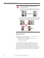
Network Connectivity and
Considerations
Within the system, the DYN module uses an RS-485 proprietary local bus for
communication with its Expansion modules. The DYN module interfaces to the
EtherNet/IP network as an adapter device using single-node addressing.
Given presence of two Ethernet RJ45 ports and integrated network switch, the
system can be used in different network topologies:
• Linear
• Star
• DLR
Given available internal switch, a linear module-to-module Ethernet connection
can be established without the need for a local Ethernet router/switch. A linear
topology is not considered to be a preferred solution, given that any module or
cable failure results in loss of communication to that part of the network,
downstream of the fault.
The star topology uses a multi-port Ethernet router/switch to establish point-topoint connections to DYN modules in the network. This topology increases
network reliability, although it doesn’t offer point-to-point connection
redundancy.
IMPORTANT
As the Dynamix 1444 Series is basically a one port device with a two-port
switch, the normal star topology redundancy using the Spanning Tree Protocol
(STP – IEEE 802.1D or its newer and faster recovery variant RSTP – IEEE
802.1w) does not work for this EtherNet/IP application.
Most preferred from the perspective of performance, support, and ease of
installation is the use of the DLR redundancy method. The Device Level Ring
(DLR) redundancy mode lets you make a simple ring-based module-to-module
connection to achieve a network with excellent reliability and fast recovery in the
presence of one failure. This is the recommended topology for machine
protection applications.
22
Rockwell Automation Publication 1444-UM001B-EN-P - August 2015
About the Dynamix 1444 Series Dynamic Measurement Module
Chapter 1
Under control of one of the ring devices configured to act as ring supervisor, a
network disruption (cable or module) can be detected and communication flow
direction reversed in a few 100 ms to become a star connection of two linear
connections.
IMPORTANT
The Dynamix DYN module cannot provide the required Ring Supervisor
capability; therefore, an EtherNet/IP controller interface with DLR functionality
is required (direct interface to Controller system), or for downstream networks
a separate 1783-ETAP (3-port EtherNet/IP tap) can be used to act as Ring
Supervisor for multiple EtherNet/IP adapters and provide connection to the
higher-level EtherNet/IP network.
Multiple rings can either be part of a further ring topology or connected with a
star topology. In the latter case, the trunking method can be used where multiple
parallel cables can be connected between switches such to increase bandwidth.
For supported products, the redundancy level is increased.
Rockwell Automation Publication 1444-UM001B-EN-P - August 2015
23
Chapter 1
About the Dynamix 1444 Series Dynamic Measurement Module
Notes:
24
Rockwell Automation Publication 1444-UM001B-EN-P - August 2015
Chapter
2
Install the Dynamix 1444 Series
Monitoring System
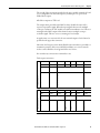
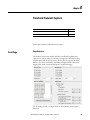
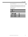
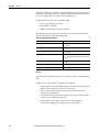
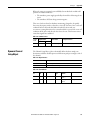
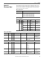
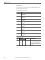
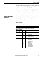
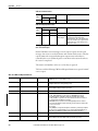
Topic
Page
Design Considerations
30
Installation Overview
43
Mount the Terminal Base Unit
45
Establish Bus Connections
46
Configure the Terminal Bases
47
Install the Module
47
Wiring Overview
50
Wiring the Main Module
51
DYN Module Transducers
63
EtherNet/IP Connector
72
4…20 mA Expansion Module
76
Wiring Expansion Modules
73
Tacho Signal Conditioning Expansion Module
78
Start the Module and Perform a Self-test
85
Rockwell Automation Publication 1444-UM001B-EN-P - August 2015
25
Chapter 1
Install the Dynamix 1444 Series Monitoring System
Environment and Enclosure
ATTENTION: This equipment is intended for use in a Pollution Degree 2 industrial
environment, in Overvoltage Category II applications (as defined in IEC 60664-1), at altitudes
up to 2000 m (6562 ft) without derating.
This equipment is not intended for use in residential environments and will not provide
adequate protection to radio communication services in such environments.
This equipment is supplied as open-type equipment for indoor use. It must be mounted within
an enclosure that is suitably designed for those specific environmental conditions that are
present and appropriately designed to prevent personal injury resulting from accessibility to live
parts. The enclosure must have suitable flame-retardant properties to prevent or minimize the
spread of flame, complying with a flame spread rating of 5VA or be approved for the application
if nonmetallic. The interior of the enclosure must be accessible only by the use of a tool.
Subsequent sections of this publication contain more information regarding specific enclosure
type ratings that are required to comply with certain product safety certifications.
In addition to this publication, see:
• Industrial Automation Wiring and Grounding Guidelines, publication 1770-4.1, for additional
installation requirements
• NEMA Standard 250 and IEC 60529, as applicable, for explanations of the degrees of
protection provided by enclosures
Prevent Electrostatic Discharge
ATTENTION: This equipment is sensitive to Electrostatic Discharge, which can cause internal
damage and affect normal operation. Follow these guidelines when you handle this
equipment:
• Touch a grounded object to discharge potential static.
• Wear an approved grounding wriststrap.
• Do not touch connectors or pins on component boards.
• Do not touch circuit components inside the equipment.
• Use a static-safe workstation, if available.
• Store the equipment in appropriate static-safe packaging when not in use.
Electrical Safety Considerations
WARNING: To comply with the CE Low Voltage Directive (LVD), all power connections to this
equipment must be powered from a source compliant with the following:
• Safety Extra Low Voltage (SELV), or
• Protected Extra Low Voltage (PELV)
To comply with UL/CUL requirements, this equipment must be powered from a source compliant
with the following:
• Limited Voltage Supply
If the input power supply is restricted to 8A, no additional protection is necessary. However, for
supplies with higher current ratings that serve multiple groups of main modules, the first
module of the daisy chain requires an 8A current limiting fuse for protection.
26
Rockwell Automation Publication 1444-UM001B-EN-P - August 2015
Install the Dynamix 1444 Series Monitoring System
Chapter 1
WARNING: All wiring must comply with applicable electrical installation requirements (for
example, N.E.C. article 501-4(b)).
North American Hazardous Location Approval
The following information applies when operating this equipment in
hazardous locations:
Informations sur l'utilisation de cet équipement en environnements
dangereux:
Products marked "CL I, DIV 2, GP A, B, C, D" are suitable for use in Class I Division 2 Groups
A, B, C, D, hazardous locations, and nonhazardous locations only. Each product is supplied
with markings on the rating nameplate indicating the hazardous location temperature
code. When combining products within a system, the most adverse temperature code
(lowest “T” number) can be used to help determine the overall temperature code of the
system. Combinations of equipment in your system are subject to investigation by the
local Authority Having Jurisdiction at the time of installation.
Les produits marqués "CL I, DIV 2, GP A, B, C, D" ne conviennent qu'à une utilisation en
environnements de Classe I Division 2 Groupes A, B, C, D dangereux et non dangereux.
Chaque produit est livré avec des marquages sur sa plaque d'identification qui indiquent
le code de température pour les environnements dangereux. Lorsque plusieurs produits
sont combinés dans un système, le code de température le plus défavorable (code de
température le plus faible) peut être utilisé pour déterminer le code de température
global du système. Les combinaisons d'équipements dans le système sont sujettes à
inspection par les autorités locales qualifiées au moment de l'installation.
WARNING:
Explosion Hazard • Do not disconnect equipment unless power has been removed or
the area is known to be nonhazardous.
• Do not disconnect connections to this equipment unless power
has been removed or the area is known to be nonhazardous.
Secure any external connections that mate to this equipment by
using screws, sliding latches, threaded connectors, or other means
that are provided with this product.
• Substitution of components may impair suitability for Class I,
Division 2.
• If this product contains batteries, they must only be changed in an
area that is known to be nonhazardous.
AVERTISSEMENT:
Risque d’Explosion • Couper le courant ou s'assurer que l'environnement est classé non
dangereux avant de débrancher l'équipement.
• Couper le courant ou s'assurer que l'environnement est classé non
dangereux avant de débrancher les connecteurs. Fixer tous les
connecteurs externes reliés à cet équipement à l'aide de vis,
loquets coulissants, connecteurs filetés ou autres moyens fournis
avec ce produit.
• La substitution de composants peut rendre cet équipement
inadapté à une utilisation en environnement de Classe I, Division
2.
• S'assurer que l'environnement est classé non dangereux avant de
changer les piles.
Do not replace components or disconnect equipment unless power has been
switched off or the area is known to be free of ignitable concentrations.
WARNING: Consider the following:
• If you insert or remove the module while Backplane power is on, an electrical
arc can occur. This could cause an explosion in hazardous location installations.
Be sure that power is removed or the area is nonhazardous before proceeding.
• When you connect or disconnect the Removable Terminal Block (RTB) with
field side power applied, an electrical arc can occur. This arc could cause an
explosion in hazardous location installations.
Be sure that power is removed or the area is nonhazardous before proceeding.
• If you connect or disconnect wiring while the field-side power is on, an
electrical arc can occur. This arc could cause an explosion in hazardous location
installations. Be sure that power is removed or the area is nonhazardous before
proceeding.
• Exposure to some chemicals will degrade the sealing properties of materials
that are used in the following devices:
• Relay RL1, Epoxy.
We recommend that you periodically inspect these devices for any degradation
of properties and replace the module if degradation is found.
Rockwell Automation Publication 1444-UM001B-EN-P - August 2015
27
Chapter 1
Install the Dynamix 1444 Series Monitoring System
ATTENTION: If this equipment is used in a manner not specified by the
manufacturer, the protection provided by the equipment may be impaired.
Before installing, configuring, operating, or maintaining this product, read this
document and the documents listed in the additional resources section for
installing, configuring, or operating equipment. Users should familiarize
themselves with installation and wiring instructions in addition to requirements of
all applicable codes, laws, and standards.
Installation, adjustments, putting into service, use, assembly, disassembly, and
maintenance shall be carried out by suitably trained personnel in accordance with
applicable code of practice. In case of malfunction or damage, no attempts at
repair should be made. The module should be returned to the manufacturer for
repair. Do not dismantle the module.
This equipment is certified for use only within the surrounding air temperature
range of -25…70 °C (-13…158 °F). The equipment must not be used outside of
this range.
Solid-state equipment has operational characteristics differing from those of
electromechanical equipment. Safety Guidelines for the Application, Installation,
and Maintenance of Solid-State Controls, publication SGI-1.1, available from your
local Rockwell Automation sales office or online at http://
www.rockwellautomation.com/literature, describes some important differences
between solid-state equipment and hard-wired electromechanical devices.
WARNING: This equipment is not resistant to sunlight or other sources of UV radiation.
Exposure to some chemicals can degrade the sealing properties of materials used in the
following devices:
• DYN module – Relay RL1, Epoxy
• Expansion Relay Module – Relay RL1 through RL4, Epoxy
28
Rockwell Automation Publication 1444-UM001B-EN-P - August 2015
Install the Dynamix 1444 Series Monitoring System
Chapter 1
European/IECex Hazardous Location Approval
The following applies to products marked II 3 G. Such modules:
• Are Equipment Group II, Equipment Category 3, and comply with the Essential Health and Safety Requirements
• relating to the design and construction of such equipment given in Annex II to Directive 94/9/EC. See the EC Declaration of Conformity at
http://www.rockwellautomation.com/products/certification for details.
• The type of protection is Ex nA IIC T4 Gc according to EN 60079-15.
• Comply to Standards: EN 60079-0:2012+A11:2013, EN 60079-15:2010, reference certificate number DEMKO14ATEX1365X.
• Are intended for use in areas in which explosive atmospheres caused by gases, vapors, mists, or air are unlikely to occur, or are likely to occur
only infrequently and for short periods. Such locations correspond to Zone 2 classification according to ATEX directive 1999/92/EC.
The following applies to products with IECEx certification. Such modules:
• Are intended for use in areas in which explosive atmospheres caused by gases, vapors, mists, or air are unlikely to occur, or are likely to occur
only infrequently and for short periods. Such locations correspond to Zone 2 classification to IEC 60079-0.
• The type of protection is Ex nA IIC T4 Gc according to IEC 60079-15.
• Such modules comply to Standards IEC 60079-0:2011, IEC-60079-15:2010, reference IECEx certificate number IECExUL14.0082X.
WARNING: Special Conditions for Safe Use
• This equipment is not resistant to sunlight or other sources of UV radiation.
• This equipment shall be mounted in an ATEX/IECEx Zone 2 certified enclosure with a minimum ingress protection rating of at
least IP54 (as defined in EN/IEC 60529) and used in an environment of not more than Pollution Degree 2 (as defined in EN/IEC
60664-1) when applied in Zone 2 environments. The enclosure must be accessible only by the use of a tool.
• This equipment shall be used within its specified ratings defined by Rockwell Automation.
• Provision shall be made to prevent the rated voltage from being exceeded by transient disturbances of more than 140% of the
rated voltage when applied in Zone 2 environments.
• Secure any external connections that mate to this equipment by using screws, sliding latches, threaded connectors, or other
means provided with this product.
• Do not disconnect equipment unless power has been removed or the area is known to be nonhazardous.
API-670 Compliance
The 1444 series is designed in accordance with the relevant sections of the 5th
Edition of the American Petroleum Institutes (API) standard 670,(1) “Machinery
Protection Systems”.
(1) Whether or not a system complies is dependent on the specific components provided, the various optional elements of the standard
that the user requires, and the configuration of the installed system.
Rockwell Automation Publication 1444-UM001B-EN-P - August 2015
29
Chapter 1
Install the Dynamix 1444 Series Monitoring System
Removal or Insertion Under Power (RIUP)
Removal or Insertion Under Power (RIUP) of any 1444 series main or expansion
module is permitted only in a nonhazardous area.
ATTENTION:
• In a hazardous area, the module must be powered down before removal.
• Always consider the consequences for the system and the monitored machine
before powering down or removing any module from service.
Design Considerations
The Dynamix modules must be placed in a protective metal enclosure with a
minimum recommended protection class of IP54.
Multiple modules can be placed in one housing, providing proper consideration
has been given to the following:
• System design and planning
• Mounting
• Module and connection accessibility
• Wiring, cabling, and routing
• System operating temperature and reliability
Electro Magnetic Compatibility (EMC) Precautions
While the module has been thoroughly tested for EMC compliance,
performance in real world situations depends on the care that is taken during
system design and installation. Follow the preferred practices listed.
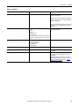
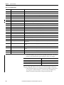
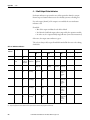
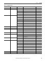
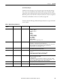
Table 4 - EMC Precautions
30
Verify metal parts are
well grounded.
• Connect all inactive metal parts, like cabinet walls and doors, to ground.
• Verify that the entire surface area is grounded and the connection to ground is low
impedance.
• Applies to the enclosure and any additional cable junction boxes.
• Avoid using aluminum parts whenever possible for grounding. Aluminum oxidizes easily,
which causes its resistance to vary.
Route cables with care.
• Divide the wiring into categories (power supply, sensors, and control signals).
• Use sufficient separation between the wire groups.
• Always run any high current/high-voltage lines and signal/data lines in separate conduits
or bundles.
• Run the signal lines as closely as possible to the ground areas (for example, bus bar, metal
rails and cabinet metal).
• Further details about wiring category and routing are provided in the following sections,
as well as wiring category identifications in the applicable specifications section.
Rockwell Automation Publication 1444-UM001B-EN-P - August 2015
Install the Dynamix 1444 Series Monitoring System
Chapter 1
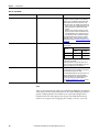
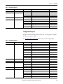
Table 4 - EMC Precautions
Use shielded/screened
cables
• Use shielded cables for all lines: signal, control, and module power.
• For the analog sensor input, each channel must be separately shielded (one shield for
each channel in a multi-core cable).
Properly terminating
the shield wires
• Keep the unshielded part of the cables as short as possible. It is ideal if only the last 100
mm of the cable is unshielded.
• Preferably, use an EMC cable gland to obtain a 360 ° ground connection to the enclosure.
Alternatively, connect the shielded wire directly after entering the cabinet or the
enclosure on a grounded bus bar and fix it with a cable clamp.
– The modules provide SHIELD terminals that can be used for shield wire termination.
However, from a performance perspective, the previously described methods are
preferred. Note that the SHIELD terminals are connected together, but otherwise
isolated from all module circuitry and the DIN rail. The installer uses one or more of the
SHIELD terminals to connect to a ground of their choosing
• Use a direct connection from the cable shield to the protective conductor.
• Connect only one end of the shield to ground; for hazardous area systems, preferably at
the field end. For known EMI hot-spots, use of overall conduit or double-shielded cabling
with shield grounded at both ends is preferred.
• When an additional junction box is used for dividing a multi-core cable into separate
cables, verify that the cable shields are isolated from the metal enclosure of the
distribution box. (The distribution box must be made of metal.)
Make a uniform
reference potential
(reference ground)
Avoid ground loops by connecting the installations and cabinets to a central ground
conductor
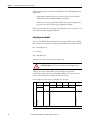
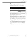
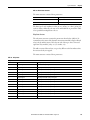
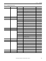
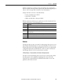
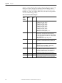
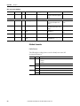
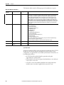
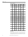
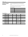
Wiring Categories and Routing
The following wiring categories are defined to help with proper segregation of all
wires and cables as part of the planning process for system layout and installation
such to promote noise immunity.
Category
Group Description
Examples
1
Control and AC Power – High-power conductors
that are more tolerant of electrical noise than
category 2 conductors and can also cause more
noise to be picked up by adjacent conductors.
• AC power lines for power supplies and I/O
circuits
• High-power digital AC I/O lines
• High-power digital DC I/O lines
2
Signal and Communication – Low-power
conductors that are less tolerant of electrical noise
than category 2 conductors. They also cause less
noise to be picked up by adjacent conductors (they
connect to sensors and actuators relatively close to
the I/O modules).
• Analog I/O lines and DC power lines for analog
circuits
• Low-power digital AC/DC I/O lines
• Low-power digital DC lines
• Communication cables
3
Intra-enclosure – Interconnect the system
components within an enclosure.
• Low voltage DC power cables
• Communication cables
Rockwell Automation Publication 1444-UM001B-EN-P - August 2015
31
Chapter 1
Install the Dynamix 1444 Series Monitoring System
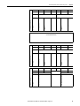
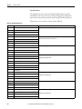
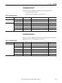
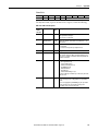
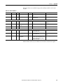
To guard against coupling noise from one conductor to another, the following
general guidelines when routing wires and cables (both inside and outside of an
enclosure) apply.
Category
Routing Guidelines
1
These conductors can be routed in the same cable tray or raceway with machine power conductors of up
to 600V AC.
2
If it must cross power cabling, cross at right angles.
• Route at least 1.5 m/5 ft. from high-voltage enclosures or sources of RF/microwave radiation.
• If the conductor is in a metal wireway or conduit, each segment of that wireway or conduit must be
bonded to each adjacent segment so that it has electrical continuity along its entire length and must
be bonded to the enclosure at the entry point.
• Properly shield where applicable and route in a raceway separate from category 1 conductors.
• If in a continuous metallic wireway or conduit, route at least 0.08 m/3 in. from category 1 conductors
of less than 20 A; 0.3 m/1 ft. from AC power lines of 20 A or more, but only up to 100 kVA; 0.6 m/2 ft.
from AC power lines of greater than 100 kVA.
• If not in a continuous metallic wireway or conduit, route at least 0.15 m/6 in. from category 1
conductors of less than 20A; 0.3 m/1 ft. from AC power lines of 20 A or more, but only up to 100 kVA;
0.6 m/2 ft. from AC power lines of greater than 100 kVA.
3
Route conductors external to all raceways in the enclosure or in a raceway separate from any category 1
conductors with the same spacing as listed for category 2 conductors, where possible.
Use the spacing that is given in these general guidelines with the following
exceptions:
• Where connection points (for conductors of different categories) on a
device are closer together than the specified spacing
• Application-specific configuration for which the spacing is described in a
publication for that specific application
These guidelines are for noise immunity only. Follow all local codes for safety
requirements.
Given the Dynamix 1444 series system component top and bottom I/O access,
we recommend that you use cable ducts to organize and provide separation of I/
O wiring.
In the case of high-voltage relay contact wiring (120/250V AC) and/or high
current load, assign top or bottom relay contacts or use Expansion bus extension
cables to position applicable relay modules in a more suitable location within the
overall system.
32
Rockwell Automation Publication 1444-UM001B-EN-P - August 2015
Install the Dynamix 1444 Series Monitoring System
Chapter 1
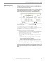
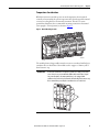
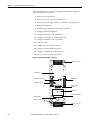
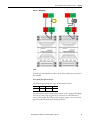
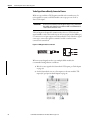
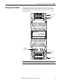
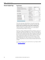
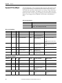
Temperature Considerations
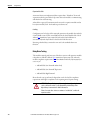
While the 1444 series modules operate at rated temperature when mounted
vertically or horizontally, the system components have been designed for natural
convection cooling based on a horizontal orientation. Therefore to assure
optimal heat dissipation the recommended mounting orientation is horizontal
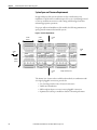
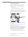
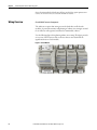
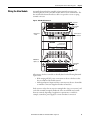
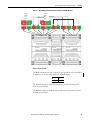
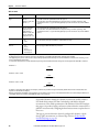
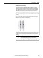
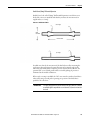
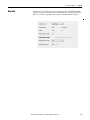
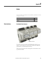
(in an upright / vertical position) as shown in Figure 1.
Figure 1 - Module Mounting Position
1444-RELX
1444-RELX
2RB
1444-TSCX02-0
itioner
Signal Cond
Tachometer
PWR LNS
MS
00-04RB
Relay
PWR LNS
PWR LNS
MS
R0
R1
R2
MS
R0
R1
R2
00-04RB
Relay
R3
R3
OP0 OP1
CH0 CH1
04-01RA
1444-DYN
ent
Measurem
Dynamic
RUN
PWR
32476-M
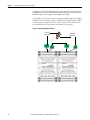
The module plastics design enables natural convection or unducted airflow by its
ventilation slots on both sides of the module such to support a “chimney effect”
from bottom to top.
IMPORTANT
As where the terminal base of Expansion modules has a fully passive nature,
some electronics are present within the DYN module terminal base. Despite
low-power dissipation, the main terminal base is also equipped with
ventilation slots and some level of internal airflow ducting from bottom to top.
We recommend that you verify these ventilation slots are not blocked.
Rockwell Automation Publication 1444-UM001B-EN-P - August 2015
33
Chapter 1
Install the Dynamix 1444 Series Monitoring System
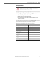
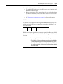
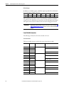
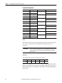
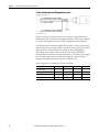
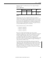
Based on maximum current load models, including internal module power
dissipation of its DC power and externally connected power sources, an estimate
can be made of total internal power dissipation within the enclosure to provide
guidance to select an enclosure or plan for required temperature control measures
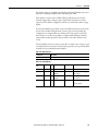
inside your enclosure.
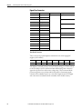
Module Type
Maximum Power Dissipation
Main
9.0 W
Relay
2.3 W
4…20 mA
3.6 W
Tacho Signal Conditioning
3.0 W
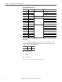
Together with known (maximum) system heat dissipation from all used
components that are planned for your enclosure, the following approximate
equations. They are based on using no active method of heat dissipation control
(like fans or air conditioning), can be used to calculate either cooling surface
requirement for enclosure and/or internal cabinet temperature rise.
Metric
English
Where:
• T is the temperature difference between inside air and
outside ambient (°C)
• Q is heat generated in enclosure (W)
• A is enclosure surface area (m2)
The exterior surface of all six sides of an enclosure is
calculated as follows.
A = 2dw + 2dh +2wh
Where d (depth), w (width) and h (height) are in meters.
Where:
• T is the temperature difference between inside air and
outside ambient (oF)
• Q is heat generated in enclosure (W)
• A is enclosure surface area (ft2)
The exterior surface of all six sides of an enclosure is
calculated as follows.
A = (2dw + 2dh +2wh)/144
Where d (depth), w (width) and h (height) are in inches.
The system components are designed for internal enclosure surrounding air
temperatures of up to a maximum of 70 °C (158 °F) (measured 1 in. below the
main module) based on natural convection cooling and specified air space
clearances around the Dynamix 1444 series system.
Outcome of calculations can show that it is can be more efficient to provide a
means of cooling rather than increase of cabinet size. Contact your cabinet
manufacturer for options available to cool your cabinet.
34
Rockwell Automation Publication 1444-UM001B-EN-P - August 2015
Install the Dynamix 1444 Series Monitoring System
Chapter 1
All system components can measure and monitor internal operating
temperatures, a feature that is highly recommended to be used to control overall
system operating temperature during normal use.
Module specifications indicate a maximum-internal operating temperature
reference for each module type.
Despite that the amount of (maximum) heat dissipation remains unchanged, use
of slightly assisted cooling, also called unducted airflow, have a considerable
impact (5…10 °C) (9…18 °F) on internal operating temperatures of system
components.
There is one configuration aspect that can reduce the dissipation load of each
DYN module by about 0.8 W, despite that typ typically the maximum heat
dissipation is fixed (and actual dissipation heat dependent on module
configuration and operating state.)
When powered, the buffered outputs consume a significant amount of quiescent
operating power (approximately 0.8W), which also imparts more heat. Because
the buffered outputs are infrequently used in most applications, it is
recommended that the buffered outputs not be powered during routine
operation.
See Buffered Outputs on page 60 for information on how to enable/disable the
outputs.
Reliability Considerations
Closely related to the previous section, overall system reliability is greatly affected
by operating temperatures. Therefore, it is highly recommended to minimize the
internal operating temperatures of the modules.
Rockwell Automation Publication 1444-UM001B-EN-P - August 2015
35
Chapter 1
Install the Dynamix 1444 Series Monitoring System
System Space and Clearance Requirements
Design and layout of the system enclosures is a key consideration in any
installation. Verify that there is sufficient space for access to (and fitting/removal
of ) the top and bottom connectors, and a wiring/cable ducting scheme that
maintains appropriate separations.
For proper airflow and installation of the module, the following minimum-air
spacing must be maintained around the system.
Figure 2 - Clearance Requirements
102 mm
(4.92 in.)
54 mm
(2.13 in.)
50 mm
2 in.
25 mm
1 in.
25 mm
1 in.
158 mm
(6.22 in.)
50 mm
2 in.
Height: 125 mm (4.92 in.)
The 50 mm/2 in. clearance above and below the modules, in combination with
45 ° angled, pluggable connections, provides for:
• Use of tooling to make/remove electrical connections
• Visible wire identification
• Sufficient physical space to insert/remove pluggable connections
• Optimized air volume per module in relation to thermal performance
36
Rockwell Automation Publication 1444-UM001B-EN-P - August 2015
Install the Dynamix 1444 Series Monitoring System
Chapter 1
Wiring Requirements
WARNING: All wiring must comply with applicable electrical installation
requirements (for example, N.E.C. article 501-4(b)).
All modules (whether main or Expansion) have four removable connectors where
the field wiring is made. They come in a choice of spring cage or screw
connection. Both types benefit from the following:
• Screwdriver axis parallel to conductor axis
• Positive connector retention (captive screws)
• Test connections for 1.2 mm (0.047 in.) diameter test pins or 1 mm
(0.039 in.) test plugs
The DYN module connectors are 16 way and the Expansion module connectors
are 6 way. Each is keyed appropriate to location and module type.
Manufacturer technical data for these connectors is as follows.
Attribute
Value
Tightening torque, mon- max (screw type only)
0.22…0.25 N•m (0.16…0.18 ft·lbf)
Normal cross-section
1.5 mm2 (0.002in2)
Stripping length
9 mm (0.35in)
Conductor cross-section solid or stranded min- max
0.14…1.5 mm2 (0.0002…0.002in2)
Conductor cross-section stranded with ferrule without
plastic sleeve min- max
0.25…1.5 mm2(0.0003…0.002in2)
Conductor cross-section stranded with ferrule with plastic
sleeve min- max
0.25…0.5 mm2 (0.0003…0.0007in2)
Conductor cross-section AWG/kcmil min- max - screw
clamp type
28…16 mm2
Conductor cross-section AWG/kcmil min- max - spring
clamp type
26…16 mm2
AWG according to ULL/CUL min- max -screw clamp type
30…16 mm2
AWG according to ULL/CUL min- max -spring clamp type
28…16 mm2
Rockwell Automation Publication 1444-UM001B-EN-P - August 2015
37
Chapter 1
Install the Dynamix 1444 Series Monitoring System
Use solid or stranded wire. All wiring must meet the following specifications:
• Minimum insulating rating of 300V
• Soldering the conductor is not allowed
• Wire ferrules can be used with stranded conductors; copper ferrules
recommended
• Single wire per connection
Module Power Supply Requirements
The Dynamix 1444 series system must be powered by single or redundant,
18…32V DC supplies as follows:
• To comply with the CE Low Voltage Directive (LVD), all power
connections to this equipment must be powered from a source compliant
with the following:
• Safety Extra Low Voltage (SELV), or
• Protected Extra Low Voltage (PELV)
• To comply with UL/CUL requirements, this equipment must be powered
from a source compliant with the following:
• Limited Voltage Supply
If the input power supply is restricted to 8A, no additional protection is
necessary. However, for supplies with higher current ratings that serve multiple
groups of main modules, the first module of the daisy chain requires an 8A
current limiting fuse for protection.
Power return line of the main-system power supply must be grounded for
electrical safety reasons.
The required power supply rating can be calculated based on the following (per
module) allowances.
38
Module Type
Power Load
18V Supply
24V Supply
32V Supply
Main
11.5 W
640 mA
480 mA
360 mA
Expansion relay
1.6 W
90 mA
70 mA
50 mA
Expansion
4…20 mA
0.76 W
40 mA
30 mA
22 mA
Expansion TSC
4W
225 mA
170 mA
125 mA
Rockwell Automation Publication 1444-UM001B-EN-P - August 2015
Install the Dynamix 1444 Series Monitoring System
Chapter 1
Each redundant supply must be able to provide the full load, no facility for load
sharing is provided, and the higher of the two applied voltages powers the
module.
There are internal protective (non-replaceable) fuses on each of the power inputs
and on the bus supply to the Expansion modules. In addition, there is similar
protection on each of the (main and Expansion) modules.
The Expansion modules are only powered by the bus and from a main module
base. Removal of any module (main or Expansion) does not affect power
distribution to any other module in a system.
Grounding Scheme
The system is isolated from ground and to maintain isolation between multiple
interconnected modules, whether they are main or Expansion modules.
Shield connections are common to one another for each module and its terminal
base, but otherwise isolated from the module circuitry. These connections are
provided as a termination point for cable screens/shields and, where applicable,
for protective ground connections to accessible metal part. One or more must be
used to connect the Shield bus to a local ground as the base module is not
grounded to the DIN rail.
Use these grounding requirements to verify the safest electrical operating
circumstances and to help avoid EMI and ground noise that can cause
unfavorable operating conditions for the Dynamix 1444 series system:
• Module Grounding - Provide AWG 16 connection to ground for each
Dynamix 1444 Series system module to an available Shield connection
terminal.
• 24V Common Grounding - Given that module power supplies are
galvanically isolated, it is recommended that the DC voltage supply return
line to the Dynamix modules is grounded.
• Transducers – verify that transducers are electrically isolated from ground.
Cable shields must be grounded at one end of the cable and the other end
not connected. It is recommended, where possible, to ground the cable
shield at the instrument side (PE terminals, protective earth ground bar, or
cable glands) and not at the transducer end.
Rockwell Automation Publication 1444-UM001B-EN-P - August 2015
39
Chapter 1
Install the Dynamix 1444 Series Monitoring System
Local Bus Connection (main/expansion)
A Common-bus runs along the base parts of the main and its associated
Expansion modules, which interconnect with ribbon cable. It integrates the
following:
• Serial (communication) bus - between the main and its associated
Expansion modules
• Power bus - Expansion modules are powered from the module base
• Tacho bus - the TSC provides up to two tacho signal outputs(1)
The system is installed with an associated Expansion module fitted to the right
side of the module. The base-mounted headers are latched and, for additional
security, cannot be removed (or inserted) while there is a module in place on that
base.
Figure 3 - Expansion Base Part with Left and Right Ribbon Cable Fitted
Left ribbon
towards host
DYN module.
Right ribbon towards next
expansion module or the left
side of the next (non-host)
main module.
The DIP switch towards the bottom of Figure 3 contributes to the expansion
module bus address so that a like-for-like Expansion module replacement retains
the earlier address.
Only the Relay Expansion module uses the DIP switch address. Up to three relay
modules can be used per main (host) module.
To install, join the bases of a module and its associated Expansion modules by
connecting the right side of one to the left side of the next by using the supplied
ribbon cables. These cables are included with each main and expansion module
terminal base. Continue these interconnections across all modules that are
intended to share the tacho bus of a TSC module, and note the following:
• One tacho bus can support a maximum of six main modules
• One (and only one) TSC Expansion module can be used per tacho bus
(1) While the serial and power buses are specific to one DYN module and its associated Expansion modules, the tacho bus extends to
serve tacho signals to multiple main modules.
40
Rockwell Automation Publication 1444-UM001B-EN-P - August 2015
Install the Dynamix 1444 Series Monitoring System
Chapter 1
Using Local Bus Extension Cables
The Dynamix 1444 series implements a Local Bus that connects modules to:
• Provide power and communication between an Expansion Module and its
Host module.
• Pass the Speed Signals (TTL) from a Tachometer Signal Conditioner
Module to other main modules on a network.
If no expansion modules are used in a system, then the modules do not need
connected.
In cases where it is necessary to separate modules, two extension cables are
provided:
1444-LBXC-OM3-01
Local Bus Extender Cable (0.3 m)
1444-LBXC-1MO-O1
Local Bus Extender Cable (1.0 m)
IMPORTANT The extension cables are intended for IN CABINET use only. The
ribbon cables are only minimally shielded. Consequently, care
must be taken to assure that cables are not routed across or near to
high voltage or other cables that can induce noise into the
network.
When connecting modules, be sure that the right sides of two main
modules are never connected. While the connectors are keyed to
prevent this, it is possible to defeat the keying by twisting the cable
or by removing the keys.
Rockwell Automation Publication 1444-UM001B-EN-P - August 2015
41
Chapter 1
Install the Dynamix 1444 Series Monitoring System
WARNING: Connecting the RIGHT sides of two main modules could result in
damage to the modules and unexpected or improper operation of any
connected expansion modules.
The Local Bus Extension cables are designed (keyed) to allow connection of the
RIGHT side of any main module to the LEFT side of any main or expansion module,
as illustrated below:
Any other connection that results in the RIGHT sides of two MAIN
MODULES (1444-DYN02-01RA) being connected is not allowed,
including when one or more expansion modules are between them.
Relay Contact Protection
Measures to limit contact wear and arcing across the contacts of a mechanical
relay are highly dependent on the following:
• The current and voltage being switched and whether AC or DC
• The load type (resistive or inductive)
• System factors such as wiring
Due to this application dependency, it is not possible to integrate contact
protection circuitry within the Dynamix hardware. It remains the system
designer’s/installer’s responsibility to take appropriate external measures to
mitigate these risks that are based on the reliability and functional safety
requirements that can apply. Commercial surge suppressors (often DIN rail
mounting) can be based on RC, MOV, or Diode protection methods. In general,
it is recommended to provide protection equipment close to its originating
source.
42
Rockwell Automation Publication 1444-UM001B-EN-P - August 2015
Install the Dynamix 1444 Series Monitoring System
Installation Overview
Chapter 1
Installation of the Dynamix 1444 Series system is based on one or more main
modules and associated Expansion modules. The mounting arrangement, from
left to right, can be summarized as follows:
• Main module
– Expansion modules
• Main module
– Expansion modules
Figure 4 - Main Terminal Base – Overview
Upper base connector
PID label area
Left EXP bus
connector
DIN rail set screws (2 ea)
Right EXP bus
Base-to-module
connector
Electronics
module coding
slots
Ethernet address
Lower base
connector
32478-M
Bottom set screws (2 ea)
Rockwell Automation Publication 1444-UM001B-EN-P - August 2015
43
Chapter 1
Install the Dynamix 1444 Series Monitoring System
When installing the system, follow these instructions and install/configure the
components in the following order.
1. Review the safety instructions.
2. Review the network connectivity considerations.
3. Review the system design guidelines, considerations, and requirements.
4. Mount the terminal base.
5. Establish expansion bus connections between modules.
6. Configure the main terminal base.
7. Configure the Auxiliary relay terminal base.
8. Configure the Auxiliary 4…20 mA terminal base.
9. Configure the Auxiliary TSC terminal base.
10. Install the module.
11. Configure the main module connectors.
12. Configure the main module transducers.
13. Configure the Expansion module connectors.
14. Start the module and perform a Self-test.
Figure 5 - Expansion Terminal Base – Overview
Upper base connector
PID label area
DIN rail set screws (2 ea)
Right EXP bus
Left EXP bus connector
Base-to-module
connector
PID label area
Module type label area
Address switches
Bottom set screws (2 ea)
Lower base connector
44
Rockwell Automation Publication 1444-UM001B-EN-P - August 2015
Install the Dynamix 1444 Series Monitoring System
Mount the Terminal
Base Unit
Chapter 1
The following generic DIN rail mounting scheme applies to all terminal base
mounting.
1. Hook the base assembly from the bottom under the DIN rail. The
presence of coding switches identifies the bottom side of the terminal base.
2. Hook over the top and let gravity drop the terminal base into place.
3. The terminal base is in the center position to the DIN rail. Once hooked,
fasten the two center (set) screws to secure the base to the rail.
Rockwell Automation Publication 1444-UM001B-EN-P - August 2015
45
Chapter 1
Install the Dynamix 1444 Series Monitoring System
4. Tighten the two bottom set screws to secure the terminal base to the base
plate such to prevent rocking effect while applying mechanical pressure to
the base.
M
Reverse the process to remove a base. Loosen the screws to create sufficient
clearance for removal of the terminal base.
Establish Bus Connections
Before configuring the terminal base and installing the main module, establish
the Expansion bus connections between modules. The Expansion bus provides
power and communication from a DYN module to associated Expansion
modules positioned to the right and distributes the tacho bus to up to six main
modules. These modules include the TSCX modules host, and mounted to the
left or right of the TSCX module.
Based on system design, the required module-to-module connections can be
made with interconnect cables (refer to the Local Bus (module to module,
interconnect cables) section in Local Bus Connection (main/expansion) on
page 40). These ribbon cable assemblies can then be fitted between various
module types.
46
Rockwell Automation Publication 1444-UM001B-EN-P - August 2015
Install the Dynamix 1444 Series Monitoring System
Chapter 1
We recommend that you combine the installation of the ribbon interconnect
cables with the process of mounting the terminal bases. This way, the bases can be
clamped to the DIN rail and the interconnect cable can easily be fitted without
subjecting it to excessive mechanical stress.
1. Install and secure the first terminal base.
2. Install the interconnection cable to the first module (right side).
3. Install the second terminal base.
4. Connect the interconnection cable to the second module (left side).
5. Secure the second terminal base.
Verify that the ribbon cable interfaces are properly locked down in the headers.
Access to the connector interfaces is further protected once the main modules are
installed.
Configure the Terminal Bases
The following configuration settings must be made or validated on the terminal
bases before installation of the designated modules.
Configure the Main Terminal Base
The module terminal base provides three decimal coding switches used to define
the last octet of the TCP/IP address of the module.
The IP address of the main module is composed of four suboctets that are
separated by dots to conform to the IPv4 structure. Each suboctet can be
configured with a number from 1 to 254. As shipped from the factory, the default
IP address of a module is aaa.bbb.ccc.ddd.
These switches can be used for automatic configuration or definition of the last
octet of a static (Class C) IP address.
Rockwell Automation Publication 1444-UM001B-EN-P - August 2015
47
Chapter 1
Install the Dynamix 1444 Series Monitoring System
These settings, from left to right, are on the bottom:
• 000 – Automatic address assignment (default)
• 001…254 – Static IP address setting (for example, 192.168.1.xxx)
• 255...887, 889...999 - Invalid address
If set to any of these values the module powers up in Module Fault.
• 888 - Reset.
When set, after power-up, the module immediately executes an out-of-box
reset. See Resetting the Module on page 197 for further information.
The rotary switches can be adjusted by using a small flathead screwdriver.
Configure the Relay Terminal Base
The two pole dip-switch setting on the Expansion Relay terminal base is used to
define the Expansion Relay module offset address. Given that up to three Relay
modules can be fitted per main module, the following configurations can be
defined.
These settings, from left to right, are on the bottom:
• 00: Not allowed
• 01: Relay Module 1
• 10: Relay Module 2
• 11: Relay Module 3
IMPORTANT
A base switch address setting of (00) is illegal for a relay module and causes the
relay module to display a critical error (solid red Module Status Indicator).
Configure the 4…20 mA Terminal Base
The two pole dip-switch setting on the Expansion 4…20 mA terminal base is
used to define the Expansion bus address for the single 4…20 mA module that
can be fitted per main module.
These settings, from left to right, are on the bottom:
• 00: 4…20 mA Analog Expansion Module
• 01…11: Not used
Settings for the AOFX module include:
• The AOFX module applies a fixed (internal) address that requires the
terminal base switch to be set to 00.
• A DYN module can only host one AOFX module.
48
Rockwell Automation Publication 1444-UM001B-EN-P - August 2015
Install the Dynamix 1444 Series Monitoring System
Chapter 1
Configure the Tacho Signal Conditioning Terminal Base
The two pole dip-switch setting on the Expansion TSC terminal base is used to
define the Expansion bus address for the single TSC module that can be fitted
per main module.
These settings, from left to right, are on the bottom:
• 00: Tacho Signal Conditioner Expansion (TSCX) Module
• 01…11: Not used
TSCX:
• The TSCX module applies a fixed (internal) address that requires the
terminal base switch to be set to 00.
• A DYN module can only host one TSCX module.
• Only one TSCX module can be connected to the same 1444 Series
Expansion bus.
Install the Module
Main and expansion modules are readily fitted to their respective bases, with
correct alignment, and connector engagement being supported by the following
features:
• Module coding pin (main module only)
• Base module upper and lower connector guidance
• Module to base connector guidance and alignment
Before installing the module, check that there is no damage (bent pins) on the
main/Expansion module to base connector.
Figure 6 - Module-to-Base Position
4-01RA
1444-DYN0
nt
Measureme
Dynamic
RUN
PWR
32480-M
Rockwell Automation Publication 1444-UM001B-EN-P - August 2015
49
Chapter 1
Install the Dynamix 1444 Series Monitoring System
Once the main module is fitted onto the base, use the four captive quarter-turn
screws, one in each corner, to secure the module to its base.
Wiring Overview
General Module Connecter Arrangements
The 1444 series requires that wiring is routed to both above and below the
modules. So particular attention and planning of cabinet wire routing is essential
for an efficient, well-organized, and therefore maintainable, cabinet.
Use the following figure when planning cabinet wire routing. The figure provides
an overview of the locations of the connectors that are associated with the
significant function of each module.
Figure 7 - General Module
50
Rockwell Automation Publication 1444-UM001B-EN-P - August 2015
Install the Dynamix 1444 Series Monitoring System
Wiring the Main Module
Chapter 1
An installed system has four removable 16-way terminal connectors, two
interfacing directly to the removable module, and two to the terminal base. The
base and module-mounted headers are able to accept either a screw or spring
terminal connector.
Figure 8 - Main Module Connectors
Upper Base
Connector
Upper Module
Connector
Ethernet Port 2
+ Status
Ethernet Port 1 +
Status Indicators
1444-DYN04-01RA
Dynamic Measurement
PWR
RUN
BNC Buffered
Outputs (0–3)
Lower Module
Connector
Lower Base
Connector
Allocations to the base or module are broadly based on the following functional
requirements:
• Wide-ranging 24V DC power connections are direct to the base so that
they are unaffected by module removal.
• Main signal inputs/outputs and relay connections are direct to the module
to minimize connection length and number of interfaces.
Each connector is keyed to its respective mating header (two per connector) and
each of the terminals is uniquely numbered. Some external links can be made
between terminals, depending on application requirements, to enable, for
example, a transducer power supply for a 2-wire transducer connection.
Rockwell Automation Publication 1444-UM001B-EN-P - August 2015
51
Chapter 1
Install the Dynamix 1444 Series Monitoring System
Upper Base Connector
Terminal
Name
Application
Description
49
RET_1
Module Power
Supply 1 Return
50
RET_1
51
+24V_1
52
+24V_1
53
RET_0
54
RET_0
55
+24V_0
56
+24V_0
57
OVR
58
OVR
59
Shield
60
Shield
61
Shield
62
Shield
63
Shield
64
Shield
Supply 1 +24V
Supply 0 Return
Supply 0 +24V
Buffered Outputs
Override High
Override Low
Shield
Cable shield connection points
Main Module Connectors
These connections provide duplicate terminals for twin, wide ranging DC
supplies (24V nominal).
56
55
54
53
52
51
50
49
+24V-0
+24V-0
RET_0
RET_0
+24V-1
+24V-1
RET_1
RET_1
The duplicate terminals provide a means for daisy chaining power from one base
to the next (subject to an overall current limit and knowing a star connection
approach is preferred to avoid excessive voltage drop.) There is internal diode
protection against reverse polarity and for the purposes of automatic supply
selection when redundant sources are connected to inputs 0 and 1. The supply
side connections are isolated from the remainder of the module circuitry.
52
Rockwell Automation Publication 1444-UM001B-EN-P - August 2015
Install the Dynamix 1444 Series Monitoring System
Chapter 1
Wiring Power
Figure 9 connects positive and negative power to the first (from left) of two
identical connectors for each. See Main Module Connectors on page 52 for the
complete list of power connections.
Figure 9 - Typical Wiring for Single and Redundant Power Solutions
4VQQMZ
7%$
1PXFS
4VQQMZ
4VQQMZ
7%$
1PXFS
4VQQMZ
Wiring Power to Multiple Modules
Figure 10 shows positive and negative power IN connected to the first of two
identical connectors for each, and power OUT from the second of two identical
connectors. See Upper Base Connector on page 52 for the complete list of power
connections.
Rockwell Automation Publication 1444-UM001B-EN-P - August 2015
53
Chapter 1
Install the Dynamix 1444 Series Monitoring System
Figure 10 - Typical Wiring for Single Power Solutions to Multiple Module
4VQQMZ
7%$
1PXFS
4VQQMZ
Figure 11 shows positive and negative power IN connections to the first of two
identical connectors for each, and power OUT from the second of two identical
connectors. See Upper Base Connector on page 52 for the complete list of power
connections.
54
Rockwell Automation Publication 1444-UM001B-EN-P - August 2015
Install the Dynamix 1444 Series Monitoring System
Chapter 1
Figure 11 - Typical Wiring for Redundant Power Solutions to Multiple Modules
4VQQMZ
7%$
1PXFS
4VQQMZ
4VQQMZ
7%$
1PXFS
4VQQMZ
Buffered Output Override
The Buffered Output ‘Override’ connections, pins 57 and 58 on the 1444-TB-A
terminal base, are used to enable/disable the buffered outputs.
58
57
OVR
OVR
The buffered outputs are enabled (powered) when no connection is present
between pins 57 and 58.
The buffered outputs are disabled (not powered) when a connection is present
between pins 57 and 58.
Rockwell Automation Publication 1444-UM001B-EN-P - August 2015
55
Chapter 1
Install the Dynamix 1444 Series Monitoring System
In applications where the buffered outputs are infrequently used a switch can be
installed between pins 57 and 58. When installed, opening the switch enables the
buffered outputs, and closing the switch disables the outputs.
It is possible to use a common switch to manage the buffered outputs of multiple
modules as the override pins are Opto-isolated from the module circuitry. When
a common switch is required, wire one contact to pin 57 of the module nearest
the switch and the other to pin 58 of each module to be managed.
Figure 12 - Wiring Buffer Outputs Override
Override Low
Buffer Outputs
56
Rockwell Automation Publication 1444-UM001B-EN-P - August 2015
Override High
Buffer Outputs
Install the Dynamix 1444 Series Monitoring System
Chapter 1
Consider the following with the module:
• The module ships with a jumper installed between pins 57 and 58, which
disables the buffered outputs.
• When connecting pin 58 from multiple modules to a single module's pin
57, allow for a maximum 3 mA current sink for each connected override
input.
• See Temperature Considerations on page 33 for further information.
Shield Connections
The module is, by design, isolated from ground. All shield connections on this
and the lower base connector are common to one another (a “shield bus”), but
otherwise isolated.
64
63
62
61
60
59
Shield
Shield
Shield
Shield
Shield
Shield
Shield connections are provided as a termination point for cable screens/shields,
one or more can be used to connect the shield bus to a local ground of the user’s
choosing.
IMPORTANT
When working with the shield bus remember the following:
• The shield bus of each main and expansion module must be individually
connected to ground by at least one shield pin wired directly to ground.
• For installations where EMI issues are anticipated, or when EMI is found to
be a problem, wire cable shields directly to ground rather than to the shield
bus of the module.
Rockwell Automation Publication 1444-UM001B-EN-P - August 2015
57
Chapter 1
Install the Dynamix 1444 Series Monitoring System
Upper Module Connector
Terminal
Name
Application
Description
33
NO
Relay Outputs
Normally Open
34
C
Common
35
NC
Normally Closed
36
SPARE
Do not connect
37
O1L
Opto-isolated Outputs
38
O1H
Digital Output 1 High
39
O0L
Digital Output 0 Low
40
O0H
Digital Output 0 High
41
RET
42
BUFF3
Channel 3 Signal
43
RET
Channel 2 Return
44
BUFF2
Channel 2 Signal
45
RET
Channel 1 Return
46
BUFF1
Channel 1 Signal
47
RET
Channel 0 Return
48
BUFF0
Channel 0 Signal
Buffered Outputs
Digital Output 1 Low
Channel 3 Return
Relay Output
There is one SPDT relay included in the DYN module with the three contact
connections being made available at the terminals. A typical purpose for this
module relay is to signal module status.
35
34
33
NC
C
NO
NC – Normally closed
C – Common
NO– Normally open
‘Normal’ is the relay contact state when un-powered.
58
Rockwell Automation Publication 1444-UM001B-EN-P - August 2015
Install the Dynamix 1444 Series Monitoring System
Chapter 1
Figure 13 - Wiring Relays
Spare
Terminal 36 is left unused for isolation reasons. Do not make any connections to
this terminal.
Opto-isolated (Open Collector) Outputs
The DYN module includes two Opto-isolated outputs, 0 and 1.
40
39
38
37
00H
00L
01H
01L
The connections are functionally polarity sensitive and are designated H (High)
and L (Low). As the name suggests, these connections are isolated from any
others on the module. These Opto-isolated outputs support reverse connection
protection within defined current load specifications.
Rockwell Automation Publication 1444-UM001B-EN-P - August 2015
59
Chapter 1
Install the Dynamix 1444 Series Monitoring System
Buffered Outputs
In addition to the BNC outputs, a buffered output is provided for each channel
(0...3) on the upper module connector.
48
47
46
45
44
43
42
41
BUFF0
RET
BUFF1
RET
BUFF2
RET
BUFF3
RET
Although having independent resistive current limiting, the buffered and BNC
outputs of any one channel share the same drive circuitry. All signal-related inputs
and outputs, unless otherwise indicated, share the same analog ground/return.
By default the buffered outputs are not powered and no signal is available. See
Buffered Output Override on page 55 for more on how to enable the Buffered
Outputs.
IMPORTANT
Lower Module Connector
The following are functions of the lower module connector.
Sensor Connections
The lower module connector is where the sensor connections are made.
60
Terminal
Name
Application
Description
1
TXP0
Sensor 0
Transducer 0 Power
2
SIG0
3
SIG0
4
RET0
5
TXP1
6
SIG1
7
SIG1
8
RET1
9
TXP2
10
SIG2
11
SIG2
12
RET2
13
TXP3
14
SIG3
15
SIG3
16
RET3
Transducer 0 Signal
Transducer 0 Return
Sensor 1
Transducer 1 Power
Transducer 1 Signal
Transducer 1 Return
Sensor 2
Transducer 2 Power
Transducer 2 Signal
Transducer 2 Return
Sensor 3
Rockwell Automation Publication 1444-UM001B-EN-P - August 2015
Transducer 3 Power
Transducer 3 Signal
Transducer 3 Return
Install the Dynamix 1444 Series Monitoring System
Chapter 1
For each channel (0...3), there is a set of four connections:
• Transducer power (configurable per channel for negative or positive
supply, or constant current)
• Duplicate signal input connections
• Signal return connection
Providing duplicated input signal connections accommodates various both 2wire and 3-wire transducers. For 2-wire constant current sensors, the appropriate
supply is configured and an external link is made to connect signal and power
output connections. A further signal connection and associated return lets the
sensor be connected without placing multiple wires in one terminal.
All signal inputs are single-ended with a ±24V range and designed for
transducers that provide an output voltage proportional to the measured physical
parameter. The transducer power is individually configurable per channel for one
of the three following outputs: +24V, 4 mA constant current or +24V or -24V at
up to 25 mA. Besides these functional operating modes, the transducer power
output can also be configured as disabled.
Rockwell Automation Publication 1444-UM001B-EN-P - August 2015
61
Chapter 1
Install the Dynamix 1444 Series Monitoring System
Lower Base Connector
Terminal
Name
Application
Description
17
T0SIG
Tach 0
Tach 0 Signal
18
T0RET
19
Shield
20
Shield
21
T1SIG
22
T1RET
23
Shield
24
Shield
25
L0SIG
26
L0RET
27
Shield
28
Shield
29
L1SIG
30
L1RET
31
Shield
32
Shield
Tach 0 Return
Shield
Shields
Tach 1
Tach 1 Signal
Tach 1 Return
Shield
Shields
Logical Input
Input 0 Signal
Input 0 Return
Shield
Shields
Logical Input
Input 1 Signal
Input 1 Return
Shield
Shields
Shield
Shield connections are provided as a termination point for cable screens/shields;
one or more can be used to connect Shield to a local ground of the user’s
choosing.
IMPORTANT
There is no internal connection between the Shield Bus and ground. A separate
connection must be made between one terminal shield pin and a suitable
ground location.
Logic Inputs
The DYN module includes two logic inputs, 0 and 1.
25
26
L0SIG
L0RET
27
28
29
30
L1SIG
L1RET
These are not isolated from other module circuitry; the signal input has a resistive
pull-up to 5V and the return connection is analog ground/return. Logic inputs
have various possible uses (configuration-dependent), including alarm gating and
SPM controls.
62
Rockwell Automation Publication 1444-UM001B-EN-P - August 2015
Install the Dynamix 1444 Series Monitoring System
Chapter 1
Tacho Inputs
The DYN module includes two local tacho inputs, 0 and 1.
17
18
19
T0SIG
T0RET
20
21
22
T1SIG
T1RET
These are not isolated from other module circuitry; the signal input has a resistive
pull-up to 5V and the return connection is analog ground/return. These local
inputs are designed for situations where there is a TTL level tacho signal
available, a tacho sensor with an open collector output (such as NPN type), a
connection to an Opto output on another Dynamix module, or the TTL output
from an XM-220 Dual Speed module (1440-SPD02-01RB). In most situations,
the preferred method of providing tacho signals to the module is through the
TSC Expansion module.
DYN Module Transducers
Proximity Probes
The following are examples of proximity probes.
Figure 14 - ECP Connections
ECP Driver
32487-M
Module Channel
0
1
2
3
Output
2 or 3
6 or 7
10 or 11
14 or 15
Common
4
8
12
16
-24V
1
5
9
13
Shield
any terminal base shield pin
upper: 59…64
lower: 19, 20, 23, 24, 27, 28, 31, 32
The channel must be configured for a negative 24V supply and either of the two
signal connections can be used as in Figure 14.
Rockwell Automation Publication 1444-UM001B-EN-P - August 2015
63
Chapter 1
Install the Dynamix 1444 Series Monitoring System
Figures 15…18 show typical wiring diagrams for channels 0…3 of an eddy current
probe sensor.
Figure 15 - Channel 0 Wiring
%SJWFS
4IJFME'MPBUJOH
$PNNPO
4JHOBM0VUQVU
4IJFME
7%$
3FDPNNFOEFETIJFMEQJODPOOFDUJPOCVUNBZCFMBOEFEUPBOZBWBJMBCMFTIJFMEDPOOFDUJPO
Figure 16 - Channel 1 Wiring
%SJWFS
4IJFME'MPBUJOH
$PNNPO
4JHOBM0VUQVU
4IJFME
7%$
3FDPNNFOEFETIJFMEQJODPOOFDUJPOCVUNBZCFMBOEFEUPBOZBWBJMBCMFTIJFMEDPOOFDUJPO
Figure 17 - Channel 2 Wiring
%SJWFS
4IJFME'MPBUJOH
$PNNPO
4JHOBM0VUQVU
4IJFME
7%$
3FDPNNFOEFETIJFMEQJODPOOFDUJPOCVUNBZCFMBOEFEUPBOZBWBJMBCMFTIJFMEDPOOFDUJPO
64
Rockwell Automation Publication 1444-UM001B-EN-P - August 2015
Install the Dynamix 1444 Series Monitoring System
Chapter 1
Figure 18 - Channel 3 Wiring
%SJWFS
4IJFME'MPBUJOH
$PNNPO
4JHOBM0VUQVU
4IJFME
7%$
3FDPNNFOEFETIJFMEQJODPOOFDUJPOCVUNBZCFMBOEFEUPBOZBWBJMBCMFTIJFMEDPOOFDUJPO
2-wire Acceleration, Pressure, or Piezoelectric Velocity Sensors
The channel must be configured for a positive, constant current supply and the
transducer power output must be connected to the spare signal connection (link
terminals 1 and 2 in channel 0, example above.) A list of appropriate terminals for
each channel follows.
Typical Core Designation
Channel 0
Channel 1
Channel 2
Channel 3
SIG (+)
3
7
11
15
Return (-)
4
8
12
16
Then link these terminals:
1 and 2
5 and 6
9 and 10
13 and 14
Figures 19…22 show typical wiring for 2-wire constant current sensors including
IEPE Acceleration, Velocity, and Pressure Sensors.
Figure 19 - 2-wire IEPE Sensors Channel 0 Wiring
1JO"4JHOBM
1JO#$PNNPO
$BCMFTIJFMEOPU
DPOOFDUFEBUUIJTFOE
$PNNPO
4JHOBM
4IJFME
3FDPNNFOEFETIJFMEQJODPOOFDUJPOCVUNBZCFMBOEFEUPBOZBWBJMBCMFTIJFMEDPOOFDUJPO
Rockwell Automation Publication 1444-UM001B-EN-P - August 2015
65
Chapter 1
Install the Dynamix 1444 Series Monitoring System
Figure 20 - 2-wire IEPE Sensors Channel 1 Wiring
1JO"4JHOBM
1JO#$PNNPO
$BCMFTIJFMEOPU
DPOOFDUFEBUUIJTFOE
$PNNPO
4JHOBM
4IJFME
3FDPNNFOEFETIJFMEQJODPOOFDUJPOCVUNBZCFMBOEFEUPBOZBWBJMBCMFTIJFMEDPOOFDUJPO
Figure 21 - 2-wire IEPE Sensors Channel 2 Wiring
1JO"4JHOBM
1JO#$PNNPO
$BCMFTIJFMEOPU
DPOOFDUFEBUUIJTFOE
$PNNPO
4JHOBM
4IJFME
3FDPNNFOEFETIJFMEQJODPOOFDUJPOCVUNBZCFMBOEFEUPBOZBWBJMBCMFTIJFMEDPOOFDUJPO
Figure 22 - 2-wire IEPE Sensors Channel 3 Wiring
1JO"4JHOBM
1JO#$PNNPO
$BCMFTIJFMEOPU
DPOOFDUFEBUUIJTFOE
$PNNPO
4JHOBM
4IJFME
3FDPNNFOEFETIJFMEQJODPOOFDUJPOCVUNBZCFMBOEFEUPBOZBWBJMBCMFTIJFMEDPOOFDUJPO
66
Rockwell Automation Publication 1444-UM001B-EN-P - August 2015
Install the Dynamix 1444 Series Monitoring System
Chapter 1
3-wire Acceleration Sensors or Other 3-wire Transducer Systems
Configure the channel for the appropriate polarity supply (+25V or -25 V). A list
of appropriate terminals for each channel follows.
Typical Core Designation
Channel 0
Channel 1
Channel 2
Channel 3
Power Supply
1
5
9
13
SIG (+)
2 or 3
6 or 7
10 or 11
14 or 15
Return (-)
4
8
12
16
In general, most 3-wire transducer systems requiring +25V or -25V at no more
than 25 mA can be accommodated by connecting as above.
3-wire sensors are wired identically to eddy current probes (power polarity is set
in module configuration). See Figures 15-18 for wiring illustrations.
2-wire Self-Generating Velocity Sensors
Being self-generating, no transducer power connection is required. A list of
appropriate terminals for each channel follows.
Typical Core Designation
Channel 0
Channel 1
Channel 2
Channel 3
SIG (+)
2 or 3
6 or 7
10 or 11
14 or 15
Return (-)
4
8
12
16
Also use this wiring solution for externally powered 2-wire sensors.
Rockwell Automation Publication 1444-UM001B-EN-P - August 2015
67
Chapter 1
Install the Dynamix 1444 Series Monitoring System
3-wire Acceleration and Temperature Sensor
Such a sensor has two outputs and therefore occupies two input channels of a
DYN module. The acceleration and temperature signals are allocated to channels
in separate channel pairs so that the module configuration can be optimized.
The vibration channel must be configured for a positive, constant current supply
and the transducer power output that is connected to the spare signal connection
(link terminals 1 and 2 in channel 0/2, example in the preceding graphic.)
Depending on the transducer that is used, the sensor can power both the
vibration and the temperature sensing circuitry from one constant current supply.
For sensor types that require a separate power supply for each, repeat power
linking and configuration for the temperature channel as well.
A list of appropriate terminals for each channel follows.
68
Typical Core Designation
Channel 0
Channel 1
Channel 2
Channel 3
Acceleration SIG (+)
3
7
-
-
Return (-)
4
8
-
-
Then link these terminals:
1 and 2
5 and 6
-
-
Temperature SIG (+)
-
-
11
15
Rockwell Automation Publication 1444-UM001B-EN-P - August 2015
Install the Dynamix 1444 Series Monitoring System
Chapter 1
Temperature Transmitter
Configure the channel for a +24V supply. A load resistor is required at the input
terminals to provide the necessary current/voltage conversion. In addition to
resistance value and precision (functional requirements), consider resistor power
rating pertaining to heating and maximum surface temperature under normal and
fault conditions.
A list of appropriate terminals for each channel follows.
Typical Core Designation
Channel 0
Channel 1
Channel 2
Channel 3
Power
1
5
9
13
Return (-)
2
6
10
14
Fit Load Resistor
3 and 4
7 and 8
11 and 12
15 and 16
Complete the configuration as follows:
• Configure the sensitivity as: Load R * 16/TX Range (millivolt/degree)(1)
• Set an appropriate offset so 4 mA = 0 °.
(1) For slightly higher accuracy, include the effect of the channel input resistance.
Rockwell Automation Publication 1444-UM001B-EN-P - August 2015
69
Chapter 1
Install the Dynamix 1444 Series Monitoring System
Tacho Signal from a Directly Connected Source
While it is expected that a TSC Expansion module is the normal source of a
tacho signal for a system, each DYN module can accept up to two ‘local’ or
‘direct’ tacho inputs.
IMPORTANT
As these are not isolated from other module circuitry, it is not recommended
that multiple tacho inputs from across different 1444 Series DYN modules are
connected to the same tacho source.
The local inputs are designed for situations where there is a TTL level tacho
signal available, a tacho sensor with an open collector output (such as NPN type)
or connection to an Opto output on another module. For any of the three signal
source types, connect the signal to terminal 17 and the common/return
connection to terminal 18.
Figure 23 - NPN type transducer connection
32488-M
When an external signal is used to serve multiple DYN modules, the
recommended wiring solution is as follows.
1. Wire the source signal to the first modules TTL inputs, per Tacho Inputs
on page 55.
2. On the first module, wire one of its outputs, to the next module's TTL
inputs.(#1) per Opto-isolated Outputs on page 52.
70
Rockwell Automation Publication 1444-UM001B-EN-P - August 2015
Install the Dynamix 1444 Series Monitoring System
Chapter 1
Example of wiring Discrete Output 0 to Tacho Input 0
Example of wiring Discrete Output 1 to Tacho Input 1
3. Daisy chain further modules be repeating #1 and #2.
4. To output the TTL signal the wired Opto-isolated Output must be
configured to replicate the “Local TTL Tach 0 Input” or “Local TTL Tach
1 Input”, as appropriate. See Hardware Configuration on page 98.
Use this method to daisy chain the external TTL signal to be sure that there is
isolation between modules. However, it can induce some amount of phase error.
Rockwell Automation Publication 1444-UM001B-EN-P - August 2015
71
Chapter 1
Install the Dynamix 1444 Series Monitoring System
EtherNet/IP Connector
Typically, Ethernet network connections are made with pre-assembled (standard)
patch cords to interconnect modules according to the desired network topology.
Each module has an integrated switch and two functionally equal (Port 1 and
Port 2) RJ45 connectors.
The total length of Ethernet cable connecting main-to- main, main-to-controller,
or main-to-switch must not exceed 100 m (328 ft.).
If the entire channel is constructed of stranded cable (no fixed cable), then
calculate maximum length as follows.
Maximum Length = (113-2N)/y, meters
Where:
• N = the number of connections in the channel
• y = the loss factor compared to fixed cable (typically 1.2…1.5)
IMPORTANT
See Ethernet Cables, channel class and category and recommended cables
under “Cable, Connector, and Mounting Accessories,” (page 12) foro further
information on Ethernet connectivity.
Wire the RJ45 connector as shown.
72
8
NC
7
NC
6
RD-
5
NC
4
NC
3
RD+
2
TD
1
TD+
Rockwell Automation Publication 1444-UM001B-EN-P - August 2015
Install the Dynamix 1444 Series Monitoring System
Wiring Expansion Modules
Chapter 1
An Expansion module has four removable 6-way terminal connectors, two
interfacing directly to the removable module and two to the terminal base. The
base and module-mounted headers are able to accept either a screw or spring
terminal connector.
Upper base connector
Upper module
connector
1444-TSCX02-02RB
Tachometer Signal Conditioner
PWR LNS MS
CH0 CH1 OP0 OP1
BNC buffered
outputs (two)
Lower module
connector
Lower base connector
IMPORTANT
BNC outputs apply only to the TSC Expansion module type.
Rockwell Automation Publication 1444-UM001B-EN-P - August 2015
73
Chapter 1
Install the Dynamix 1444 Series Monitoring System
Allocations to the base or module are broadly based on the following functional
requirements:
• Signal inputs/outputs and relay connections are direct to the module to
minimize connection length and number of interfaces.
• The base connectors provide mainly Shield connections, noting the same
base part is used across all three types of Expansion module.
Each connector is keyed to its respective mating header (two per connector) and
each of the terminals is uniquely numbered.
Relay Expansion Module
There are four SPDT relays included in the relay output module (0...3) with the
three contact connections for each being made available at the module terminals.
NC – Normally closed
C – Common
NO – Normally open
‘Normal’ is the relay contact state when unpowered.
ATTENTION: The relay connections can carry high voltage.
The base part carries mainly Shield connections that are provided as a
termination point for cable screens/shields. In addition, one or more must be
used to connect Shield to a local ground of the user’s choice.
Do not make any connections to terminals 9, 10, 19 or 24.
Terminal
24
23
22
21
20
19
Name
NOT USED
SH
SH
SH
SH
NOT USED
74
Rockwell Automation Publication 1444-UM001B-EN-P - August 2015
Do not connect
Cable shield connection points
Shield
Do not connect
Description
Upper Base Connector
Application
Terminal
18
17
16
15
14
13
Name
REL 2 NC
REL 2 COM
REL 2 NO
REL 3 NC
REL 3 COM
REL 3 NO
Application
Relay 2
Normally closed
Chapter 1
Description
Common
Normally open
Normally closed
Normally open
Relay 3
Terminal
1
2
3
4
5
6
Name
REL 0 NC
REL 0 COM
REL 0 NO
REL 1 NC
REL 1 COM
REL 1 NO
Application
Relay 0
Common
Upper Module Connector
Install the Dynamix 1444 Series Monitoring System
Normally open
8
9
Name
SH
SH
NOT USED
Application
Shield
Cable shield connection points
Normally open
Common
7
Common
Normally closed
Terminal
Normally closed
Description
Relay 1
Description
10
11
12
SH
SH
Rockwell Automation Publication 1444-UM001B-EN-P - August 2015
Cable shield connection points
Shield
Do not connect
Lower Base Connector
Lower Module Connector
1444-RELX00-04RB Relay Expansion Module
and 1444-TB-B Terminal Base
75
Chapter 1
Install the Dynamix 1444 Series Monitoring System
4…20 mA Expansion Module
The Analog Output module provides four channels of 4...20 mA output. For
each output, specific High (HI) and Low (LO) signal connections are provided
(despite the High/Low description these connections are polarity insensitive).
Eight electrically connected shield connections are provided.
The 4...20 mA Expansion module requires loop power, a supply in the range of
18V to 32V DC at 26 mA, to be provided to each output.
Supplying Loop Power
When loop power is not provided by other devices, a 24V supply must be
provided.
The output connections are isolated from one another and the remainder of the
module circuitry. While individual supplies can be applied per channel output, it
is possible to deploy a common supply for multiple channels if maintaining interchannel isolation is not important.
Above: Example wiring scheme where PLC, DMM, Recorder represent the 4...20
mA load.
As shown in the preceding graphic:
• Connect the positive (+) power to the module output high connections
(pins 1, 5, 14, and 18).
• Connect the negative (-) power to the module output low connections
(pins 2, 6, 13, and 17)
• Do not make any connections to terminals 3, 4, 9, 10, 15, 16, 19, or 24.
76
Rockwell Automation Publication 1444-UM001B-EN-P - August 2015
Install the Dynamix 1444 Series Monitoring System
Chapter 1
Use of the same power supply that serves the Dynamix module is allowed, if it can
serve the additional load. However, when the same power supply is serving
additional loads, such as additional Dynamix modules. While the supply can
adequately serve the rated (normal) operating loads of all devices, surge currents
during startup of other devices, surge currents during startup of other devices can
affect the current provided to Loop Power, which can result affect current levels
(measurements) on the system.
Terminal
24
23
22
21
20
19
Name
NOT USED
SH
SH
SH
SH
NOT USED
18
17
16
15
14
13
Name
OUTPUT 2 HI
OUTPUT 2 LO
NOT USED
NOT USED
OUTPUT 3 HI
OUTPUT 3 LO
Do not connect
Terminal
Low
4…20 mA Output 3
Do not connect
Low
High
Upper Module Connector
Description
Application 4…20 mA Output 2
High
Upper Base Connector
Description
Cable shield connection points
Shield
Do not connect
Application
1444-AOFX00-04RB Analog Output Expansion Module
and 1444-TB-B Terminal Base
Rockwell Automation Publication 1444-UM001B-EN-P - August 2015
77
Install the Dynamix 1444 Series Monitoring System
Terminal
1
2
3
4
5
6
Name
OUTPUT 0 HI
OUTPUT 0 LO
NOT USED
NOT USED
OUTPUT 1 HI
OUTPUT 1 LO
7
8
9
Name
SH
SH
NOT USED
10
11
12
SH
SH
Shield
Do not connect
Cable shield connection points
Lower Base Connector
Description
Application Shield
Low
Do not connect
Terminal
High
Low
4…20 mA Output 2
High
Lower Module Connector
Description
Application 4…20 mA Output 3
Cable shield connection points
Chapter 1
Tacho Signal Conditioning Expansion Module
The lower module connector carries the tacho sensor inputs, while the upper
module connector carries the local tacho outputs. In addition, the TSC module
has two further buffered outputs made available at the BNC connectors.
For each of the two input channels, there is a separate signal and return
connection and, if needed, a transducer power supply connection. The polarity of
that supply output is configurable on a per channel basis.
When the input to a TSC module is a multiple event per revolution pulse, there
are choices to what some of the outputs represent.
The first of the two outputs that is provided on the upper module terminals (18
and 14) is automatically configured to be the same as the output provided on the
tacho bus (expected to be one event per revolution).
78
Rockwell Automation Publication 1444-UM001B-EN-P - August 2015
Install the Dynamix 1444 Series Monitoring System
Chapter 1
The second of the two outputs provided on the upper module terminals (17 and
13) is configurable to be the same frequency as the input or as a processed/
divided down output.
All of these outputs are TTL level.
The output that is provided on the BNC is always a buffered version of the
respective input tacho signal. When the input signal is known to be multiple
events per revolution, the TSC module sets either status indicator 6 or 7 blue as a
warning that the BNC output of that channel carries a multiple event per
revolution signal. This is to serve as a warning to a local analyst.
A signal return, one connection for the two terminal outputs of each channel, is
provided on the upper base connector.
Otherwise, the base part carries mainly Shield connections that are provided as a
termination point for cable screens/shields. In addition, one or more must be
used to connect Shield to a local ground of the user’s choice.
Do not make any connections to terminals 9 or 10.
Terminal
24
23
22
21
20
19
Name
RET
SH
SH
SH
SH
RET
Application
Tacho Return
Shield
Cable shield connection points
18
17
16
15
14
13
Name
T0 OUT 0
T0 OUT 1
RET
RET
T1 OUT 0
T1 OUT 1
Application
Tacho 0 Outputs
1/Rev
1/Rev
Rockwell Automation Publication 1444-UM001B-EN-P - August 2015
N/Rev
Tacho 1 Outputs
Return
Tacho Returns
Return
Return
Return
Terminal
N/Rev
Description
Tacho Return
Description
Upper Module Connector
Upper Base Connector
Tacho input connections:
79
Chapter 1
Install the Dynamix 1444 Series Monitoring System
Terminal
1
2
3
4
5
6
Name
TXP 0
SIG 0
RET 0
TXP 1
SIG 1
RET 1
Application
Tach 0 Input
Transducer 0 Return
8
9
Name
SH
SH
NOT USED
Application
Shield
Cable shield connection points
Transducer 1 Return
Transducer 0 Signal
7
Transducer 1 Signal
Transducer 0 Power
Terminal
Transducer 1 Power
Description
Tach 1 Input
Description
10
11
12
SH
SH
TSCX Module Transducers
The TSCX supports four types of speed sensor inputs:
• Eddy Current Probe
• NPN/PNP Proximity Switch
• Self-Generating magnetic Sensors
• TTL Signal Input
80
Rockwell Automation Publication 1444-UM001B-EN-P - August 2015
Cable shield connection points
Shield
Do not connect
Lower Base Connector
Lower Module Connector
1444-TSCX02-02RB Tachometer Signal Conditioner Expansion Module
and 1444-TB-B Terminal Base
Install the Dynamix 1444 Series Monitoring System
Chapter 1
Proximity Probes
The connected channel of the Tachometer Signal Conditioner must be
configured with:
• Transducer Type = Eddy Current Probe System, and
• Transducer Power = -24V DC
Wire the eddy current probe.
Figure 24 - Channel 0 wiring for an eddy current probe sensor
Shield
Floating
Common
Signal
Shield
-24V DC
* Recommended shield pin connection but can be landed to any available shield connection.
Figure 25 - Channel 1 wiring for an eddy current probe sensor
Shield
Floating
Common
Signal
Shield
-24V DC
* Recommended shield pin connection but can be landed to any available shield connection.
Rockwell Automation Publication 1444-UM001B-EN-P - August 2015
81
Chapter 1
Install the Dynamix 1444 Series Monitoring System
NPN/PNP Proximity Switch
The connected channel of the Tachometer Signal Conditioner must be
configured with:
• Transducer Type = NPN Proximity Switch, or
• Transducer Type = PNP Proximity Switch, and
Transducer Power = +24V DC
Wire the proximity switch as illustrated.
Figure 26 - Channel 0 wiring for an NPN/PNP Proximity Switch
Shield
Floating
Common
Signal
Shield
-24V DC
* Recommended shield pin connection but can be landed to any available shield connection.
Figure 27 - Channel 1 wiring for an NPN/PNP Proximity Switch
Shield
Floating
Common
Signal
Shield
-24V DC
* Recommended shield pin connection but can be landed to any available shield connection.
82
Rockwell Automation Publication 1444-UM001B-EN-P - August 2015
Install the Dynamix 1444 Series Monitoring System
Chapter 1
Self-generating magnetic Sensor
The connected channel of the Tachometer Signal Conditioner must be
configured with:
• Transducer Type = Self-generating Magnetic Pickup, and
• Transducer Power = OFF
Wire the pickup as illustrated.
Figure 28 - Channel 0 wiring for a Self-generating magnetic Sensor
Shield
Floating
Common
Signal
Shield
* Recommended shield pin connection but can be landed to any available shield connection.
Figure 29 - Channel 1 wiring for a Self-generating magnetic Sensor
Shield
Floating
Common
Signal
Shield
* Recommended shield pin connection but can be landed to any available shield connection.
Rockwell Automation Publication 1444-UM001B-EN-P - August 2015
83
Chapter 1
Install the Dynamix 1444 Series Monitoring System
TTL Output Sensor
For any sensor or device that provides a TTL signal, such as a Hall Effect sensor,
the connected channel of the Tachometer Signal Conditioner must be
configured with:
• Transducer Type = TTL Signal, and
• Transducer Power = OFF
Wire the pickup as illustrated in the following.
Figure 30 - Channel 0 wiring for a TTL Signal
Shield
Floating
Common
Signal
Shield
* Recommended shield pin connection but can be landed to any available shield connection.
Figure 31 - Channel 0 wiring for a TTL Signal
Shield
Floating
Common
Signal
Shield
* Recommended shield pin connection but can be landed to any available shield connection.
84
Rockwell Automation Publication 1444-UM001B-EN-P - August 2015
Install the Dynamix 1444 Series Monitoring System
Start the Module and
Perform a Self-test
Chapter 1
After the modules are wired, power can be applied to test the installation. At
power-up, each module performs an initial Self-test.
Until a configuration is downloaded, and an Ethernet connection made, after the
Self-test cycle the modules move to an idle state. Table 5 describes the status
indicators:
Table 5 - Dynamic Measurement Module
Status
Color
Indicator
Behavior
Status
Color
Indicato
r
Behavior
PWR
Green
Solid
DSP
Green
Flashing
RUN
Green
Flashing
OK
Green
Solid
MS
Green
Solid
CH0
Green
Solid
NS
Green
Solid or Flashing
CH1
Green
Solid
CH2
Green
Solid
CH3
Green
Solid
RLY
Green
Solid
OS
Green
Solid
If the Status Indicators are not as shown above, see Table 54 on page 236.
Rockwell Automation Publication 1444-UM001B-EN-P - August 2015
85
Chapter 1
Install the Dynamix 1444 Series Monitoring System
Expansion Module Startup Behavior
During power-up expansion, Module Status Indicators provide the address
setting of the module. See Startup Behavior on page 242, for more information.
Table 6 - Tacho Signal Conditioner Expansion Module
Status Indicator Color
Behavior
Status Indicator Color
Behavior
PWR
Green
Solid
CH0
Green or
Blue
Solid
LNS
Green
Solid
CH1
Green or
Blue
Solid
MS
Green
Flashing
OP0
Green
Solid
OP1
Green
Solid
If the Status Indicators are not as shown above, see Table on page 239.
Table 7 - Relay Expansion Module
Status
Color
Indicator
Behavior
Status
Color
Indicato
r
Behavior
PWR
Green
Solid
R0
Green
Solid
LNS
Green
Solid
R1
Green
Solid
MS
Green
Flashing
R2
Green
Solid
R3
Green
Solid
If the Status Indicators are not as shown above, see Table on page 241.
Table 8 - Analog Output Expansion Module
Status
Color
Indicator
Behavior
Status
Color
Indicato
r
PWR
Solid
OP0
Green
Behavior
OFF
LNS
Green
Solid
OP1
OFF
MS
Green
Flashing
OP2
OFF
OP3
OFF
If the Status Indicators are not as shown above, see Table on page 240.
86
Rockwell Automation Publication 1444-UM001B-EN-P - August 2015
Chapter
3
Configure the 1444 Dynamic
Measurement Module
This chapter details how to define and configure the 1444 dynamic measurement
module and set associated parameters.
Topic
Page
General Page
88
Module Definition
88
Internet Protocol Page
101
Port Configuration Page
102
Network Page
103
Time Sync Page
104
Time Sync Page
104
Hardware Configuration Page
105
Time Slot Multiplier Page
112
Speed Page
115
IMPORTANT
Many parameters presented by the AOP are named differently than in the
various objects within the module that it refers to. Consequently the parameter
names listed in the CIP Objects Library (Appendix B), in some cases, do not
match the parameters presented on the AOP.
See the Cross Reference at the beginning of the CIP Objects Library to
determine the specific names of parameters as presented on the AOP, stored in
the configuration assembly, and held in the various objects in the module.
Rockwell Automation Publication 1444-UM001B-EN-P - August 2015
87
Chapter 2
Configure the 1444 Dynamic Measurement Module
General Page
The general page contains controls to name, describe, and define the system. You
can also set the EtherNet/IP address or host name from the general page.
Figure 32 - The General Page
Module Definition
The Module Definition pages provide high-level definitions of module
application and channel function. Users must define the module at this level once
during initial installation, as the entries on this page are used throughout the
configuration to enable, disable, or qualify further configuration attributes,
selections, and options.
IMPORTANT
88
If parameters are changed in module definition, any dependent module
configuration parameters are reset to default values.
Rockwell Automation Publication 1444-UM001B-EN-P - August 2015
Configure the 1444 Dynamic Measurement Module
Chapter 2
Module Definition Versus Module Configuration
In the Logix environment, there are two steps to configure a new device:
• Defining the instance of the specific connected device
• Configuring the device.
Module Definition
Module definition is performed by using the various dialogs that are accessed
through the General Page Change button.
At minimum, the attributes that are defined in module definition include any
that affect the structure of the configuration, input, or output assemblies because
the Add-on Profile (AOP) constructs these assemblies when the module
definition is applied.
The 1444 series controller input assembly can be as simple as one measurement
from each of four DC channels or as sophisticated as over 100 values that are
measured from dynamic signals. In either case, in module definition specific
measures must be selected to include in the input assembly. To simplify the
selection and to minimize errors further along in configuration, Module
definition then includes additional dependant attributes. These attributes are
used to filter the selection of the input assembly attributes based on the
application and the types of inputs to each channel.
Other attributes that are controlled in module definition include specification of
connected expansion modules, which define the complete hardware available for
configuration, as well as other high-level attributes that are not expected to be
edited once the device is initially defined.
IMPORTANT
• When Module Definition is applied, the AOP creates instances of the
Configuration, Input, and Output assemblies. After editing an existing
Module Definition the AOP will reset only configuration parameters that
have a dependency on a changed Module Definition parameter.
• For example, if a Channel Input Type is changed then only the parameters
associated with the changed channel will be set to their default values.
Users should thoroughly review the configuration after making any change
to an existing Module Definition.
Rockwell Automation Publication 1444-UM001B-EN-P - August 2015
89
Chapter 2
Configure the 1444 Dynamic Measurement Module
Module Configuration
Module Configuration consists of all “normal configuration” pages that are
added to the tree below the standard General, Connections, and Module Info
pages.
For the Dynamix 1444 Series, much of what is enabled in these pages is
determined based on the selections in Module Definition.
Configuration attributes can be changed without concern for the physical device
definition (connected expansion modules and sensor types) such as alarm limits,
measurement definitions, and trend configuration. In many cases, the available
selections are limited by those attributes, within the available selections for that
type of device.
Expansion Device Definition Dialog
Part of defining a 1444 series module is specifying any connected expansion
modules. It can make sense to specify modules before working through the other
module definition dialogs because it defines the physical installation. The
expansion device definition dialog is used to add any expansion modules that are
hosted by the selected 1444-DYN04-01RA module.
The tool provides controls to select a device and assign an address.
From the expansion device pull-down menu select the type of expansion module
to add to the tree, and connect to the selected dynamic measurement module.
Use the address pull-down menu to select an address (0, 1, 2) for a connected
relay module (1444-RELX00-04RB). See Relay Expansion Module on page 91:
• Configuration of expansion modules is included in the configuration of
the expansion module’s host module.
• Addresses are set automatically for connected Tachometer Signal
Conditioner (1444-TSCX02-02RB) and 4…20 mA analog (1444AOFX00-04RB) expansion modules.
90
Rockwell Automation Publication 1444-UM001B-EN-P - August 2015
Configure the 1444 Dynamic Measurement Module
Chapter 2
Relay Expansion Module
Figure 33 - The Relay Expansion Module Page
Use the parameters on this page to edit the address of a connected relay
expansion module for the selected 1444-DYN04-01RA dynamic measurement
module.
Verify that the physical address set in the relay expansion module terminal base
matches the value entered here.
Rockwell Automation Publication 1444-UM001B-EN-P - August 2015
91
Chapter 2
Configure the 1444 Dynamic Measurement Module
Define Module Functionality Page
Use the define module functionality page to specify the high-level application of
the module. This page is also where the general measurement definitions for the
module and each channel are made. The selections made here are used
throughout the tool, including on other module definition pages and the
configuration pages, to guide further selections.
In configuration the relays are numbered as follows:
• 1444-DYN04-01RA onboard Relay: relay #0
• 1444-RELX00-04RB at address 0: relays #1...4
• 1444-RELX00-04RB at address 1: relays #5...8
• 1444-RELX00-04RB at address 2: relays #9...12
IMPORTANT
If edits are made to the Module Configuration, it resets all other configurations
to their default values.
Figure 34 - The Define Module Functionality Page
92
Rockwell Automation Publication 1444-UM001B-EN-P - August 2015
Configure the 1444 Dynamic Measurement Module
Chapter 2
Table 9 - Module Functionality
Parameter
Values
Comment
Power Supply
Single
Redundant
Specify if the module is powered by a single or dual power supplies.
When powered by dual supplies (redundant mode) the module monitors each power
supply input and signal its status by using bit 15 of input tag member
AuxProcesorStatus.
The status bit is set (1) if this parameter is set to Redundant (1) and either of the
supply voltages is less than 17V DC.
Redundant power is required for all API and SIL level applications (ComplianceMode
not equal to “None”).
Using External Redundant Supplies
If the application requires API-670 or SIL compliance and power redundancy is being
implemented externally, then it is necessary to connect power to both power inputs
on the module. If power is landed to only one input, and the Power Supply mode is
set to Redundant, then a fault indication is given.
Compliance
Requirement
Personality
Setting
Compliance Mode
None
0
API-670 Compliant
1
Setting
Personality
Real Time, 4 Ch – Dynamic (4 kHz) or Static
1
Real Time, 2 Ch – Dynamic (18 kHz), 2 Ch
Static
2
Real Time, 4 Ch – Dynamic (4 kHz) – Dual Path 32
Real Time, 2 Ch – Dynamic (40 kHz)
64
Multiplexed, 4 Ch – Dynamic (40 kHz) or Static – Paired
-128
For general monitoring applications that do not apply protection requirement, select
“None”.
Selecting API-670 Compliant or higher applies restrictions to the configuration that
aid in defining an API-670 machinery Protection Systems standard compliant
configuration.
When performing a safety function, the Dynamix 1444 module (including any
associated auxiliary modules) implements a range of diagnostic measures to test for
hardware or software failure. By specifying the mode in which the safety function
operates (low/high demand mode) the extent of these checks, their frequency, and
the actions on detection of a failure can all be set appropriately.
• API-670 enables a great deal of variation in many aspects of the configuration. So
setting this attribute to API-670 Compliant or higher does not by itself help ensure
that a configuration is API-670 compliant. API -670 compliance levels require realtime measurements. So the multiplexed personalities are not enabled when
compliance levels greater than None are selected.
Module Personality defines the general measurement configuration of the module,
including which channels are used, at what maximum frequency (or DC).
Two categories of Personality are provided – Real-Time and Multiplexed. Real-Time
personalities are those that provide continuous measurements that update at rates of
not slower than once every 40 milliseconds. The Multiplexed personalities update
measurements in channel pairs, although they do not necessarily alternate equally
(see Time Slot Multiplier).
The available selections are as follows.
1: Real Time, 4 Ch – Dynamic (4 kHz) or Static
All channels are available. Each channel pair can be defined for either Static (DC) or
Dynamic (AC) measurements. Dynamic channels can be configured for an Fmax up to
4 kHz (240 kCPM).
2: Real Time, 2 Ch – Dynamic (18 kHz), 2 Ch Static
Channels 0 and 1 can be configured for Dynamic (AC) measurements with an Fmax of
up to 18 kHz (1080 kCPM). Channels 2 and 3 can be used for Static (DC)
measurements.
32: Real Time, 4 Ch – Dynamic (4 kHz) – Dual Path
For measurements, this is the same as “1: Real Time, 4 Ch – Dynamic (4 kHz) or
Static”. What is different is that the module internally connects the channel 0 and 2
inputs and the channel 1 and 3 inputs.
64: Real Time, 2 Ch – Dynamic (40 kHz)
Channels 0 and 1 (pair) can be configured for Dynamic (AC) measurements with an
Fmax of up to 40 kHz (2400 kCPM), or as gSE. Channels 2 and 3 are disabled (off).
-128: Multiplexed, 4 Ch – Dynamic (40 kHz) or Static – Paired
Channels can be configured in pairs (0 and 1, 2 and 3) for Dynamic (AC)
measurements with an Fmax of up to 40 kHz (2400 kCPM), as gSE, as Static (DC)
measurements, or off.
Channel Pair measurements alternate based on the Time Slot Multiplier setting.
Rockwell Automation Publication 1444-UM001B-EN-P - August 2015
93
Chapter 2
Configure the 1444 Dynamic Measurement Module
Table 9 - Module Functionality
Parameter
Values
Comment
Ch0, Ch1, Ch2,
Ch3
0: Off
1: Dynamic
2: gSE
3: Static
Channel Type is a high-level selection that is used by the AOP (not the module) to
filter / manage further user selections in Module Definition and in Configuration.
The Channel Types that are enabled are based on the Module Personality selected.
The selections are as follows.
94
Personality
Ch0
Ch1
Ch2
Ch3
Real Time, 4 Ch –
Dynamic (5 kHz)
or Static
Off,
Dynamic,
Static
Off,
Dynamic,
Static
Off,
Dynamic,
Static
Off,
Dynamic,
Static
Real Time, 2 Ch –
Dynamic
(20 kHz), 2 Ch
Static
Off, Dynamic
Off,
Ch0 Setting
Off,
Static
Off,
Static
Real Time, 4 Ch –
Dynamic (5 kHz)
– Dual Path
Off,
Dynamic,
Static
Off,
Ch0 Setting
Off,
Dynamic,
Static
Off,
Ch2 Setting
Real Time, 2 Ch – Off,
Dynamic (40 kHz) Dynamic,
gSE
Off,
Ch0 Setting
Off
Off
Rockwell Automation Publication 1444-UM001B-EN-P - August 2015
Configure the 1444 Dynamic Measurement Module
Chapter 2
Input Data Page
Use the Input Data Page to specify the measurements to be included in the
module input assembly. The input assembly is constructed to include a fixed
Status Assembly (See Assembly Object on page 435) followed by a table that
consists of the selected measurements.
Selecting measurements to be included on the input assembly is not sufficient for
the module to produce them. Measurements must also be configured
appropriately (See Measurement Definition on page 117).
Figure 35 - The Input Data Page
Table 10 - Input Data
Parameter
Values
Comments
Speed (0)
Checked (1)
Unchecked (0)
Check this to include the Speed0 member to the input tag.
The speed written is the value measured from the TTL input (0 or 1) or from the controller output (I/O), and without
applying any Speed Multiplier that can be configured.
Tag Member: Speed0
Speed (1)
Checked (1)
Unchecked (0)
Check this to include the Speed1 member in the input tag.
The speed written is the value measured from the TTL input (0 or 1) or from the controller output (I/O), and without
applying any Speed Multiplier that can be configured.
Tag Member: Speed1
FactoredSpeed (0)
Checked (1)
Unchecked (0)
Check this to include the Factored Speed0 member to the input tag. The Factored Speed is the measured speed multiplied
by the Multiplier (specified on the Speed page).
Tag Member: FactoredSpeed0
FactoredSpeed (1)
Checked (1)
Unchecked (0)
Check this to include the Factored Speed1 member to the input tag. The Factored Speed is the measured speed multiplied
by the Multiplier (specified on the Speed page).
Tag Member: FactoredSpeed1
Speed (0) maximum
Checked (1)
Unchecked (0)
Check this to include the Speed0 max member to the input tag.
Speed maximum is the maximum observed speed measurement since last reset. This is the maximum Speed, not
Factored Speed. So it excludes any multiplier that can be specified on the Speed page.
Tag Member: Speed0 max
Rockwell Automation Publication 1444-UM001B-EN-P - August 2015
95
Chapter 2
Configure the 1444 Dynamic Measurement Module
Table 10 - Input Data
Parameter
Values
Comments
Speed (1) maximum
Checked (1)
Unchecked (0)
Check this to include the Speed1 max member to the input tag.
Speed maximum is the maximum observed speed measurement since last reset. This is the maximum Speed, not
Factored Speed. So it excludes any multiplier that can be specified on the Speed page.
Tag Member: Speed1 max
Speed (0) Rate of Change
Checked (1)
Unchecked (0)
Check this to include the Speed0RateOfChange member to the input tag. This is the Rate of Change of the Speed, not of
the Factored Speed. So it excludes any multiplier that can be specified on the Speed page.
Tag Member: Speed0RateOfChange
Speed (1) Rate of Change
Checked (1)
Unchecked (0)
Check this to include the Speed1RateOfChange member to the input tag. This is the Rate of Change of the Speed, not of
the Factored Speed. So it excludes any multiplier that can be specified on the Speed page.
Tag Member: Speed1RateOfChange
SMax pk-pk
Checked (1)
Unchecked (0)
Check this to include the S MAX magnitude member for the selected channel pair to the input tag.
Shaft Absolute pk-pk
Axial Differential Expansion
Checked (1)
Unchecked (0)
Checked (1)
Unchecked (0)
Channel Pair
Tag Member
0, 1
Ch0_1SMAXMAg
2, 3
Ch2_3SMAXMAg
Check this to include the Shaft Absolute pk-pk member for the selected channel pair to the input tag.
Channel Pair
Tag Member
0, 1
Ch0_1Shaft AbsolutePk_Pk
2, 3
Ch2_3Shaft AbsolutePk_Pk
Check this to include the Axial Differential Expansion member for the selected channel pair to the input tag.
Channel Pair
Tag Member
0, 1
Ch0_1AxialDiffExpansion
2, 3
Ch2_3AxialDiffExpansion
If the channel type is DC, then only one DC member can be selected (Axial or Radial Differential Expansion, DC
Proportional, or Rod Drop).
Radial Differential Expansion
Checked (1)
Unchecked (0)
Check this to include the Radial (Ramp) Differential Expansion member for the selected channel pair to the input tag.
Channel Pair
Tag Member
0, 1
Ch0_1RampDiffExpansion
2, 3
Ch2_3RampDiffExpansion
If the channel type is DC, then only one DC member can be selected (Axial or Radial Differential Expansion, DC
Proportional, or Rod Drop).
Overall (n)
96
Checked (1)
Unchecked (0)
Check this to include the Overall (0) member for the selected channel to the input tag.
Channel
Tag Member
0
Ch0Overall[n]
1
Ch1Overall[n]
2
Ch2Overall[n]
3
Ch3Overall[n]
Rockwell Automation Publication 1444-UM001B-EN-P - August 2015
Configure the 1444 Dynamic Measurement Module
Chapter 2
Table 10 - Input Data
Parameter
Values
Comments
Order (n) magnitude
Checked (1)
Unchecked (0)
Check this to include the Order (0) magnitude member for the selected channel to the input tag.
Order (n) Phase
Bias / Gap
FFT Band (n)
Checked (1)
Unchecked (0)
Checked (1)
Unchecked (0)
Checked (1)
Unchecked (0)
Channel
Tag Member
0
Ch0Order[n]Mag
1
Ch1Order[n]Mag
2
Ch2Order[n]Mag
3
Ch3Order[n]Mag
Check this to include the Order (0) Phase member for the selected channel to the input tag.
Channel
Tag Member
0
Ch0Order[n]Phase
1
Ch1Order[n]Phase
2
Ch2Order[n]Phase
3
Ch3Order[n]Phase
Check this to include the Bias / Gap (DC volts) member for the selected channel to the input tag.
Channel
Tag Member
0
Ch0DCV
1
Ch1DCV
2
Ch2DCV
3
Ch3DCV
Check this to include the FFT Band 0 member for the selected channel to the input tag.
Channel
Tag Member
0
Ch0FFTBand[n]
1
Ch1FFTBand[n]
2
Ch2FFTBand[n]
3
Ch3FFTBand[n]
Rockwell Automation Publication 1444-UM001B-EN-P - August 2015
97
Chapter 2
Configure the 1444 Dynamic Measurement Module
Table 10 - Input Data
Parameter
Values
Comments
Not 1x
Checked (1)
Unchecked (0)
Check this to include the Not 1x member for the selected channel to the input tag.
Proportional DC
Checked (1)
Unchecked (0)
Channel
Tag Member
0
Ch0Not1X
1
Ch1Not1X
2
Ch2Not1X
3
Ch3Not1X
Check this to include the Proportional DC member for the selected channel to the input tag.
Channel
Tag Member
0
Ch0DC
1
Ch1DC
2
Ch2DC
3
Ch3DC
• The tag value displays in the specified engineering units for the proportional value.
• If the channel type is DC, then only one DC member can be selected (Axial or Radial Differential Expansion, DC
Proportional, or Rod Drop).
Rod Drop
Checked (1)
Unchecked (0)
Check this to include the Rod Drop member for the selected channel to the input tag.
Channel
Tag Member
0
Ch0RodDrop
1
Ch1RodDrop
2
Ch2RodDrop
3
Ch3RodDrop
If the channel type is DC, then only one DC member can be selected (Axial or Radial Differential Expansion, DC
Proportional, or Rod Drop).
Select Input Data for Input Tag
The parameters on this page are used to specify measurements to be included in
the Input Tag. When a control is checked, the corresponding member is included
in the input tag.
The page is organized into top (Module level), middle (Input Pair level) and
bottom (Input level) sections.
98
Rockwell Automation Publication 1444-UM001B-EN-P - August 2015
Configure the 1444 Dynamic Measurement Module
Chapter 2
Module Level Parameters
The parameters in the top section are all associated with speed so they are not
dependent on the configuration or availability of any measurement channel.
Channel Pair Level Parameters
The parameters in this section are measurements that are made from two
measurement channels. All two channel measurements are made from channels
that are grouped into either of two pairs; channels 0 and 1 or channels 2 and 3.
There are two versions of each of the parameters that are shown in this section,
one associated with each channel pair. Click the button for pair 0, 1 or pair 2, 3 to
select the measurements for either pair.
Channel Level Parameters
The parameters in this section are measurements that are made from individual
channels.
There are four versions of each of the parameters that are shown in this section,
one associated with each channel. Click the button for channel 0 or 1, for channel
pair 0/1, or 2 or 3, for channel pair 2/3, to select the measurements for each
channel:
• The parameters on this page are used only by the AOP.
• The Module Personality and Channel Type selections of the Define
Module Functionality page filter the presented measurements.
• Selecting measurements on this page forces related configuration
definition/selections but cannot ensure that the configuration of the
measurement is appropriate for the application and the applied signals.
• Use the Copy Button to copy the Channel Pairs and Channel selections
that are visible to the other Channel Pair and Channels.
Rockwell Automation Publication 1444-UM001B-EN-P - August 2015
99
Chapter 2
Configure the 1444 Dynamic Measurement Module
Module Definition - Select Data for Output Tag
The parameters on this page are used to specify data to be included in the Output
Tag.
The module output assembly consists of one Control value and two optional
arrays of floats; two speed values and 16 alarm limit values. The optional items
are what are defined on this page.
Figure 36 - Module Definition - Select Data for Output
Table 11 - Data for Output Tag
Parameter
Values
Comments
Speed
Checked (1)
Unchecked (0)
Check this to include two speed members in the output tag.
• Speed values written to the output tag can be used to manage FFT Bands, Alarm Gating, and other speed-related functions in the
module.
• Sometimes a machine does not have a speed sensor (tachometer) available for the module to consume directly. But often the
controller knows the speed, from a drive or other system / device. While the module requires a “trigger” type signal for some
speed functions, such as Order Tracking, it needs only an RPM value for others, such as Alarm Gating.
Alarms
Checked (1)
Unchecked (0)
Check this to include 16 alarm members in the output tag.
• Alarm limit values written to the output tag can be used as Alert or Danger limit levels in one or more Measurement Alarms.
• For some applications, static alarm values are insufficient because the behavior of the measured value changes “normally” as a
function of the process. For example, the “profile” of vibration through the cycle of cutting by a machine tool follows a unique,
but repeatable, pattern as the cutting tool is at rest, moves forward, engages, cuts, disengages, retracts, and then rests again. In
other cases, the vibration response can vary “normally” based on the type of fluid being pumped, or the type of metal being
worked. In all these cases, and many more, the controller can be programmed to serve appropriate alarm limits to the module as
standard I/O. This helps ensure the detection of any deviant behavior regardless of where the process is within the profile or what
material is being processed.
100
Rockwell Automation Publication 1444-UM001B-EN-P - August 2015
Configure the 1444 Dynamic Measurement Module
Internet Protocol Page
Chapter 2
The Internet Protocol page parameters provide controls for connecting the
module to a network. See ENET-UM001 for more information.
Figure 37 - The Internet Protocol Page
Table 12 - Internet Protocol
Parameter
Values
Internet Protocol Settings
Manually configure IP settings
Obtain IP settings automatically using BOOTP
Obtain IP settings automatically using DHCP
IP settings set by switches on the module
Physical Module IP Address
N/A
Domain Name
N/A
Host Name
N/A
Subnet Mask
N/A
Gateway Address
N/A
Primary DNS Server Address
N/A
Secondary DNS Server Address
N/A
Rockwell Automation Publication 1444-UM001B-EN-P - August 2015
Comments
Type in an IP address for the system.
101
Chapter 2
Configure the 1444 Dynamic Measurement Module
Port Configuration Page
Use the Port Configuration page to enable and configure module ports.
Figure 38 - The Port Configuration Page
Table 13 - Port Configuration
Parameter
Value
Port
Enable
Link Status
Auto-Negotiate
Speed
Duplex
Port Diagnostics
102
Rockwell Automation Publication 1444-UM001B-EN-P - August 2015
Comments
Configure the 1444 Dynamic Measurement Module
Network Page
Chapter 2
Use the Network page to view the network topology and status. See ENETUM001 for more information.
Figure 39 - Network Page
Figure 40 - The Network Page
Rockwell Automation Publication 1444-UM001B-EN-P - August 2015
103
Chapter 2
Configure the 1444 Dynamic Measurement Module
Time Sync Page
Refer to ENET-UM001 for more information.
Figure 41 - The Time Sync Page
Figure 42 - The Time Sync Page
104
Rockwell Automation Publication 1444-UM001B-EN-P - August 2015
Configure the 1444 Dynamic Measurement Module
Hardware Configuration
Page
Chapter 2
Figure 43 - Configuration for Channel Inputs, Discrete Inputs, Discrete Outputs, and Dynamic
Measurement Data Storage
The Hardware Configuration Page includes parameters that are associated with
the physical inputs and outputs of the module. The page is divided into four
general sections:
• Sensor Definition: Parameters that define the sensor that is physically
connected to each channel of the module.
IMPORTANT
Because the available selections and defaults for the Sensor Definition
parameters are set by the Measurement Type selection in the Channel
Definition group, it can be easier to select the appropriate Measurement Type
value before configuring the sensor attributes.
• Channel Definition: Parameters that define the integration and filtering
requirements for each channel.
• Discrete I/O Definition: Parameters that define how the module’s discrete
input and output channels are used.
• Dynamic Data Storage: One parameter that defines how the module
internally holds dynamic data that is captured by the module.
Rockwell Automation Publication 1444-UM001B-EN-P - August 2015
105
Chapter 2
Configure the 1444 Dynamic Measurement Module
Table 14 - Hardware Configuration
Parameter
Values
Comment
Xdcr Units
The supported engineering units include the following.
Select the Engineering Units the sensor measures and to which the
transducer sensitivity is referenced (in mV/Engineering Unit).
The Channel Type (Module Definition) and the Measurement Type
determine the available selections.
V
inch/s
2
mV
m/s
m
mm/s2
2
bar
kW
UK g/min
mbar
MW
m3/min
psi
VA
gSE
A
kVA
RPM
mA
VAR
RPM/min
EU
mm
inch/s
micron
g
inch
mg
K
kVAR
Pa
o
l/min
m/s
kPa
oF
cfm
mm/s
MPa
W
US g/min
mil
C
The Engineering Units cannot be set or changed if the Channel Type is OFF or gSE.
Xdcr Sensitivity
Any real number between 1 and 20,000.
Enter the sensitivity of the connected sensor in mV/Engineering Unit (EU
as specified in Xdcr Units above).
Xdcr Power
Select from the following.
• Off
• +24V DC, 4 mA
• +24V DC, 25 mA
• -24V DC, 25 mA
Select the power option appropriate for the connected sensor.
• Select OFF for any self-powered sensor, or for sensors that are powered
from another source (including a barrier).
• +24V DC, 4 mA: This is a constant current (CC) source. It is required for
standard IEPE (ICP) accelerometers and other sensors that require a 4
mA CC source.
• +24V DC, 25 mA: This is a regulated positive voltage source. Many
position measurement sensors such as LVDTs and some vibration
sensors require a +24V supply.
• -24V DC, 25 mA: This is a regulated negative voltage source. It is
suitable for all API-670 compliant eddy current probes and other
sensors that require a -24V supply.
Xdcr High Limit (V
DC)
-24.000…24.000
High-voltage threshold for the TX OK monitoring window. A sensor bias
voltage greater than this value forces a transducer fault condition.
To aid transducer failure detection the signal input circuitry imposes, in
the absence of a functioning transducer, a bias voltage at the input. The
bias applied is automatically selected based on the power supply
configured for that channel:
Power
Typical Bias Voltage at Input
OFF
1.7 VDC
+24V DC, 4 mA
-3.9 VDC
+24V DC, 25mA
-3.9 VDC
-24V DC, 25mA
13 VDC
Within a channel pair (0&1, 2&3), there will be slight differences in the
bias voltages (particularly noticeable on the positive bias, where it is
approximately 1.3 V). This is by design and has no effect on functionality.
106
Rockwell Automation Publication 1444-UM001B-EN-P - August 2015
Configure the 1444 Dynamic Measurement Module
Chapter 2
Table 14 - Hardware Configuration
Parameter
Values
Comment
Xdcr Low Limit (V
DC)
-24.000…24.000
Low voltage threshold for the TX OK monitoring window. A sensor bias
voltage less than this value forces a transducer fault condition.
To aid transducer failure detection the signal input circuitry imposes, in
the absence of a functioning transducer, a bias voltage at the input. The
bias applied is automatically selected based on the power supply
configured for that channel:
Power
Typical Bias Voltage at Input
OFF
1.7 VDC
+24V DC, 4 mA
-3.9 VDC
+24V DC, 25mA
-3.9 VDC
-24V DC, 25mA
13 VDC
Within a channel pair (0&1, 2&3), there will be slight differences in the
bias voltages (particularly noticeable on the positive bias, where it is
approximately 1.3 V). This is by design and has no effect on functionality.
Xdcr Location
Select from the following.
• Unknown
• Radial
• Axial
Select the location of the transducer that pertains to the alignment of the
sensor with the monitored shaft.
Use Radial if the most sensitive direction of measurement is perpendicular
to the shaft.
Use Axial of the most sensitive direction of measurement is parallel to the
shaft.
The module does not use Transducer Location but retains it for reference
by higher-level systems.
Xdcr Orientation
(deg).
0…359, in 1 ° increments
Degrees are referenced (0) to the vertical top dead center (TDC) of the
shaft and increment in the clockwise direction when viewed from the
driver end of the machine train.
• The direction of shaft rotation does not affect orientation.
• Transducer orientation is used in the S MAX and Absolute Shaft
Vibration calculations and for reference by higher-level systems.
Name
0…32 characters
Name must start with a letter or underscore (“_”). All other characters can
be letters, numbers, or underscores. Name cannot contain two contiguous
underscore characters and cannot end in an underscore.
The module does not use Transducer Name but retains it for reference by
higher-level systems.
Measurement Type See following table. Also see table “Channel Application Type” in Dynamix
Configuration Manager Object.
Measurement Type selections are intended to simplify configuration of
various common applications. It defines what filtering will be applied (LP/
HP), the quality of the filtering (roll off), and if the measurement will be
integrated or double integrated.
Displays the engineering units that results from applying the
Measurement Type (function) to the selected Transducer Units. This is the
engineering unit that is associated with dynamic measures read from the
Post Filter signal source (see Filters page).
Measurement
Units
Displays the engineering units that results from applying the
Measurement Type (function) to the selected Transducer Units. This is the
engineering unit that is associated with dynamic measures read from the
Post Filter signal source (see Filters page).
N/A
Rockwell Automation Publication 1444-UM001B-EN-P - August 2015
107
Chapter 2
Configure the 1444 Dynamic Measurement Module
Table 14 - Hardware Configuration
Parameter
Values
Comment
Parameter
Values
Comment
Pt0/1)
Set bit 0 for Pt0 or bit 1 for Pt 1 in the attribute that is associated with the selected
control.
The 1444 DYN04-01RA includes two discrete TTL class input channels.
These let users physical wire an input to the module that can be used in
any of several described manners.
Discrete Inputs
Function
Description
Trip Inhibit/ Bypass
Inhibits trips with all voted alarms
that define the Logical Input as its
control
Alarm/Relay Reset
Resets all latched voted alarms
where the alarm condition has
cleared, which resets any associated
physical relays.
Voted Alarm SPM Control
Manages Setpoint Multiplication
for measurement alarms that are
inputs to the associated voted
alarm.
Voted Alarm Gate Control
Manages Alarm Gating for the
associated voted alarm.
Voted Alarm Logic Control
Use this to wire an external input
that, when actuated, forces the
associated Voted Alarm to actuate,
and therefore any relays assocated
wtih it. See I/O Control on the Voted
Alarm page for further information.
Speed 0 Fault
If wiring a TTL tacho source to the
terminal base, rather than via the
local bus, this input can be used to
communicate the tacho channel
status.
Speed 1 Fault
108
Rockwell Automation Publication 1444-UM001B-EN-P - August 2015
Configure the 1444 Dynamic Measurement Module
Chapter 2
Table 14 - Hardware Configuration
Parameter
Values
Comment
Parameter
Values
Comment
Pt0/1
-
The 1444-DYN04-01RA includes two discrete opto isolated outputs. These
provide output of selected status conditions or replication of selected
input signals. i
-
Function
Description
0
OFF
Output is not used
1-13
Voted Alarm Instance 1...13 Alarm
Alert Status
The status of the selected Voted
Alarm when the alarm is configured
to activate on an alert condition.
17-29
Voted Alarm Instance 1...13 Danger The status of the selected Voted
Alert Status
alarm when the alarm is configured
to activate on danger conditions.
33-45
Voted Alarm Instance 1...13 Fault
Alert Status
The status of the selected Voted
alarm when the alarm is configured
to activate on a transducer fault
condition.
48-49
Local TTL Tacho 0...1 Input
Replicated from the TTL signal
connected to the terminal pins
50-51
Tacho Bus 0...1
Replicated from the TTL signal
communicated over the Local Bus
52-53
Tacho Bus 0...1 Fault
The Local Bus Tacho status
54-55
Pt0...1 Discrete Input
Replicated from the Discrete Input
56-59
Transducer 0...3 Fault
Transducer Status
127
Module Status
Module Status
Discrete Outputs
Channel Type:
Input Tag
gSE
Measurement Type selections
Comment
gSE
Spike Energy (gSE) is a processing technique capable of detection of low
energy impacts. The measure is suitable for early detection of faults in
rolling element bearings or gears and detection of other periodic or
random low energy impact events.
Channel Type:
Static (DC)
Input Tag
Measurement Type selections
Comment
Rod Drop
Rod Drop
A triggered position (rod-drop) measurement taken at a fixed
(consistently the same) position of the rod during the stroke.
Axial Differential Expansion
Comp. Differential Exp. A/B (Axial)
The measurement of shaft axial displacement using a pair of axial eddycurrent-probe monitoring a shaft collar target such that the
measurement range is optimally the sum of the ranges of the individual
probes.
Radial Differential Expansion
Comp. Differential Exp. A/B (Radial)
The measurement of differential expansion with axial/radial eddycurrent-probe pair viewing concave or convex ramp shaft
Rockwell Automation Publication 1444-UM001B-EN-P - August 2015
109
Chapter 2
Configure the 1444 Dynamic Measurement Module
Proportional DC
Transmitter Temperature °F
Proportional voltage measurements
Transmitter Temperature °C
Transmitter Temperature °K
DC Current
DC Voltage
Position
Common thrust/axial position measurement. Measures the offset and
direction of movement.
Accelerometer Temperature °F
Proportional voltage measurements
Accelerometer Temperature °C
Accelerometer Temperature °K
Eccentricity
The measurement of shaft bow (the shaft peak to peak displacement) at
slow roll speed by either of two methods (with or without a speed
input).
Channel Type
Dynamic (AC)
Input Tag
Measurement Type selections
Comment
Shaft Absolute pk-pk
Shaft Relative (LP/HP filtered)
Calculates the peak to peak shaft absolute radial displacement
measured from the sum of:
A shaft to case relative displacement (eddy current probe)
measurement, and
A case absolute displacement measurement from an integrated velocity
transducer or double integrated accelerometer that is mounted in-line
with the eddy current probe.
The first channel of the pair must be the accelerometer or velocity sensor
and its Measurement Type must be one of:
absolute vibration (A to D)
absolute vibration (AV to D)
absolute vibration (V to D)
The second channel of the pair must be the displacement sensor and its
Measurement Type set to Shaft Relative (LP/HP).
110
Rockwell Automation Publication 1444-UM001B-EN-P - August 2015
Configure the 1444 Dynamic Measurement Module
Chapter 2
Channel Type
Dynamic (AC)
Input Tag
Measurement Type selections
Comment
Tags that require dynamic
measurements can be processed
using any of these Measurement
Types.
Aero Derivative (AV - V)
Applies 60 dB/octave low pass (LP) and high pass (HP) filters.
Limits the maximum frequency that the module can measure to
approximately 1665 Hz.
The tracking filter 0 measurement is the gas generator vibration, and
the tracking filter 1 measurement is the power turbine vibration.
X (shaft relative)
One eddy current probe, or the eddy current probe that is mounted in
the X-direction for an XY pair.
Applies a -24 dB/octave LP filter.
Y (shaft relative)
An eddy current probe that is mounted in the Y direction for an XY pair.
Applies -24 dB/octave filters.
X (shaft relative) – Filtered
One eddy current probe, or the eddy current probe that is mounted in
the X- direction for an XY pair.
Applies -24 dB/octave LP and HP filters.
Y (shaft relative) - Filtered
One eddy probe, or the eddy current probe that is mounted in the Ydirection for an XY pair.
Applies a -24 dB/octave LP filter.
Aero derivative (AV - D)
Applies 60 dB/octave LP and HP filters.
Specifies one level of integration (velocity to displacement).
Limits the maximum frequency that the module can measure to
approximately 1665 Hz.
The tracking filter 0 measurement is the gas generator vibration, and
the tracking filter 1 measurement is the power turbine vibration.
absolute vibration (A to A)
Non-integrated acceleration measurements.
Applies -24 dB/octave LP and HP filters.
absolute vibration (A to V)
Integrated (to velocity) acceleration measurements.
Applies -24 dB/octave LP and HP filters.
absolute vibration (A to D)
Double-integrated (to displacement) acceleration measurements.
Applies -24 dB/octave LP and HP filters.
absolute vibration (AV to V)
Non-integrated measurements from an integrating (velocity output)
accelerometer.
Applies -24 dB/octave LP and HP filters.
absolute vibration (AV to D)
Integrated (to displacement) measurements from an integrating
(velocity output) accelerometer.
Applies -24 dB/octave LP and HP filters.
absolute vibration (V to V)
Non-integrated velocity measurements.
Applies -24 dB/octave LP and HP filters.
absolute vibration (V to D)
Integrated (to displacement) velocity measurements.
Applies -24 dB/octave LP and HP filters.
Dynamic Pressure
Dynamic pressure measurements.
Applies -24 dB/octave LP and HP filters.
AC Current
Dynamic current measurements.
Applies -24 dB/octave LP and HP filters.
AC Voltage
Dynamic voltage measurements
Applies -24 dB/octave LP and HP filters.
Rockwell Automation Publication 1444-UM001B-EN-P - August 2015
111
Chapter 2
Configure the 1444 Dynamic Measurement Module
Time Slot Multiplier Page
Figure 44 - Configuration for Data Acquisition Time Slot Multiplier
Parameter
Values
Comment
Time Slot 0
0…65535
Enter the Time Slot Multiplier for channel 0 (or channel
pair 0,1).
See Page Overview for a discussion of the Time Slot
Multiplier and examples of how to use it.
Time Slot 1
0…65535
Enter the Time Slot Multiplier for channel 1.
See Page Overview for a discussion of the Time Slot
Multiplier and examples of how to use it.
Time Slot 2
0…65535
Enter the Time Slot Multiplier for channel 2 (or channel
pair 2,3).
See Page Overview for a discussion of the Time Slot
Multiplier and examples of how to use it.
Time Slot 3
0…65535
Enter the Time Slot Multiplier for channel 3.
See Page Overview for a discussion of the Time Slot
Multiplier and examples of how to use it.
112
Rockwell Automation Publication 1444-UM001B-EN-P - August 2015
Configure the 1444 Dynamic Measurement Module
Chapter 2
The Time Slot Multiplier Page is accessible when the Module Personality is set to
either of the multiplexed measurement selections:
• Multiplexed, 4 Ch – Dynamic (40 kHz) or Static – Paired
• Multiplexed, 4 Ch – Dynamic (40 kHz) or Static – Individual
IMPORTANT
• Module Personality is specified on the Module Definition >Define Module
Functionality page.
• If the Module Personality is set to “Multiplexed, 4 Ch – Dynamic (40 kHz)”
or “Static – Paired” then the Time Slot Multipliers are applied per channel
pair (channels 0 and 1 and channels 2 and 3).
When monitoring using either of the Multiplexed Personalities, the Time Slot
Multipliers are used when it is necessary for some channels to update more
frequently than other channels.
When using the Multiplexed Personalities, the module does not continuously
measure each channel. Rather, measurements are made on one channel or channel
pair at a time. Once it completes each measurement, it moves to the channel or
channel pair that is “next” on the schedule as determined by the Time Slot
Multiplier values.
If all channels have the same multiplier value, then the measurements cycle one to
the next and back to the first. But if any of the multipliers are greater than the
others then that channel or channel pair is sampled more frequently, by the ratio
of the multipliers, than the channels with lower multiplier values. Table 15 and
Table 16 provide examples of how the channels update with various multiplier
values specified.
IMPORTANT
Determining how long it takes to cycle through the channels in a multiplexed
application can be estimated by considering the measurement definition for
each channel or channel pair. In general, the time it takes to measure a channel
is equal to the period of the specified time waveform.
Rockwell Automation Publication 1444-UM001B-EN-P - August 2015
113
Chapter 2
Configure the 1444 Dynamic Measurement Module
Table 15 - Multiplier Examples for Module Personality: Multiplexed, 4 Ch – Dynamic (40 kHz) or
Static – Paired
Example 1
Multiplier
Meas.
Number
1
Example 2
1
Example 3
1
2
1
3
0.1
2.3
Channel Pair
0.1
0
2.3
0.1
2.3
(0.1)
1
(2.3)
2
(0.1)
(2.3)
(2.3)
(2.3)
(2.3)
(0.1)
(0.1)
(2.3)
5
(2.3)
6
(2.3)
(0.1)
3
4
(2.3)
(2.3)
(2.3)
(0.1)
(2.3)
(0.1)
(2.3)
7
(2.3)
(2.3)
(2.3)
(0.1)
Table 16 - Multiplier Examples for Module Personality: Multiplexed, 4 Ch – Dynamic (40 kHz) or
Static – Paired
Example 1
Multiplier
Meas.
Number
4
3
0
(0)
1
(0)
2
1
2
3
3
1
2
1
3
1
3
0
1
3
0
1
2
3
(2)
(2)
(1)
(0)
10
(1)
(0)
14
(0)
(2)
(1)
(0)
(3)
(1)
(3)
(0)
(0)
(2)
(1)
(1)
15
(2)
(0)
(2)
13
(2)
(3)
11
(0)
(3)
(2)
(1)
12
(1)
(0)
(3)
(0)
(0)
(2)
(1)
9
(0)
(0)
(2)
(0)
(2)
(2)
(0)
8
2
(1)
7
114
3
(1)
6
16
1
(0)
4
5
2
Example 3
Channel
0
3
Example 2
(2)
(2)
(0)
Rockwell Automation Publication 1444-UM001B-EN-P - August 2015
(2)
(0)
Configure the 1444 Dynamic Measurement Module
Speed Page
Chapter 2
The Speed Page parameters define the source and processing that is applied to the
module’s two speed measurements.
Figure 45 - Configure Speed Inputs
Parameter
Values
Comments
Mode
Normal (0)
Redundant (1)
In Normal mode the speed inputs are independent. In
Redundant mode, if Tach 0 is in Fault (Not OK), then Tacho
1 is used for all functions specified for Tacho 0.
Name
Blank or must start with a letter or underscore (“_”),
however, all other characters can be letters, numbers, or
underscores. Cannot contain two contiguous underscore
characters and cannot end in an underscore.
Enter a name of up to 32 characters for the selected
tachometer.
Speed Multiplier
Support for values <> 1
Enter a multiplier for the Factored Speed value.
Notes:
• There are two speed measurements available, Speed
and Factored Speed. This parameter is used to
calculate the Factored Speed.
• Factored Speed is used when the required speed is that
of a shaft that is mechanically connected to the shaft
to which the tachometer is applied.
Source
Local TTL Tach Input 0 (1)
Local TTL Tach Input 1 (2)
Tach Bus 0 (3)
Tach Bus 1 (4)
I/O Speed 0 (5)
I/O Speed 1 (6)
Each speed measurement can be processed from any type
source.
• Synchronous measurements (Filters page) and Order
Tracking (Tracking Filters pages) require speed
measured from a triggered signal source, so must be
either a Local TTL or Tacho Bus source.
• I/O Speed selections require that Speed be included in
the Controller Output assembly (in Module Definition).
Rockwell Automation Publication 1444-UM001B-EN-P - August 2015
115
Chapter 2
Configure the 1444 Dynamic Measurement Module
Parameter
Values
Comments
TTL Trigger
Positive (0)
Negative (1)
Trigger the measurement on the positive or negative
going side of the TTL signal.
Select Positive to trigger on the “leading edge”, or
Negative to trigger on the “trailing edge”.
Applicable only for speeds with a Local TTL or Tacho Bus
source.
IMPORTANT:
To assure accurate phase measurements from any
configured Tracking Filters, the trigger point on the TTL
signal must align with the trigger point on the
tachometer signal. If the TTL source is a Tachometer
Signal Conditioner Expansion (TSCX) module, then to
assure accurate phase measurements match this
parameter to the Trigger Slope defined in the Tachometer
configuration for the TSCX.
Update Rate
0.1 to 20.0 seconds
Enter the time, in seconds, between each speed
measurement used to calculate the acceleration (rate of
change) value.
Speed measurements are updated at a rate not slower
than once per 40 milliseconds but dependent on module
configuration and the overall module processing
requirements. The delta time between samples used for
the rate of change calculation will be adjusted to the
nearest interval based on the actual measurement update
rate.
Time Constant
0.1 to 20.0 seconds
Enter a time constant for use in the rate of change
calculation.
The time constant calculation effectively smooth’s the
measurements as it behaves similarly to a high pass filter.
The smaller the time constant the more responsive the
measurement is to rapid changes (or noise).
116
Rockwell Automation Publication 1444-UM001B-EN-P - August 2015
Chapter
4
Measurement Definition
Topic
Page
Filters
118
Overall
126
Tracking Filters
126
FFT
134
gSE
137
Bands
139
DC
143
Demand
155
The Input data page within Module Definition allows selection of measurements
for inclusion in the controller input assembly. However, while that reserves a spot
in the table, it doesn't define how the measurements must be calculated. The
group of pages under module definition, including filters, overall, tracking filters,
gSE, bands, DC, and demand, are where you can define the measurements.
Rockwell Automation Publication 1444-UM001B-EN-P - August 2015
117
Chapter 3
Measurement Definition
The Filters page defines the digital signal processing that is applied to each of the
channel’s two independent signal paths. You can select the output from each path
and from specific intermediate processing points as the source to calculate
measurements such as Overall levels, FFTs, and FFT Bands.
Filters
Figure 46 - Filter Configuration for Channel
Table 17 - Filters
Parameter
Values
Comments
FMAX
The available FMAX selections are as follows::
FMAX SRD Conditions
The module provides two (hardware) analog-to-digital converters (ADC’s),
one for channels 0 & 1, and one for channels 2 & 3. Each ADC samples at
93,750 samples per second (187,500 for 40 kHz personalities). However,
the ADC’s include a “Sample Rate Divide” (SRD) capability that reduces the
rate of samples output to the module. Because the sample rate drives the
resulting maximum frequency, and because it is desirable to put as much
of that processing in the hardware (rather than firmware), the Dynamix
module allows users to set the SRD value, effectively specifying the
maximum frequency (FMAX) that is available from the ADC.
Users do not directly set the SRD. Rather a menu is provided, which lists
appropriate FMAX selections that have corresponding SRD values. The
available FMAX selections vary with the personality.
The value that is written to the configuration assembly is the Sample
Rate Divisor, not the FMAX. Values from 1…32 are allowed. Not all 32
selections are provided in the FMAX menu.
The FMAX values that are listed are approximate values. Once selected the
actual FFT FMAX (what an FFT returns) is listed after “FFT FMAX”, to the
right of the menu.
In the case of synchronous sampling, (one option in the Alternate Signal
Path) the FMAX divided by the number of samples per shaft revolution
dictates the maximum machine speed that the module can successfully
monitor.
Because the module applies the SRD in hardware, rather than firmware,
specify the largest FMAX (SRD) possible to minimize any further
firmware-based decimation requirement. Doing so reduces the load on
the processor, which can improve module performance for any nonsafety or protection-related functions.
40000
1
Available for 40 kHz Module Personalities (Module
Definition), and if the Measurement Type (Hardware
Page) is one of “40 kHz absolute vibration (A to A)”, “40
kHz absolute vibration (A to V)” or “gSE”
18300
2
12200
3
9200
4
Available for the 18 kHz Module Personality (Module
Definition), and if the Measurement Type (Hardware
Page) is NOT any of the “40 kHz…”, or either of the
absolute vibration (A to A)”, “40 kHz absolute vibration
(A to V)” or “gSE”
7300
5
6100
6
5200
7
4100
9
3100
12
2000
18
1800
20
1700
22
1500
24
1400
26
1300
28
1200
30
1100
32
Available for all 4 kHz and 18 kHz Module Personalities
(Module Definition), and if the Measurement Type
(Hardware Page) is NOT a “40 kHz…” type or either of
the aero derivative types.
Available for all 4 kHz and 18 kHz Module Personalities
(Module Definition), and if the Measurement Type
(Hardware Page) is NOT a “40 kHz…” type.
Note: If the Channel measurement type = Aeroderivative the Range is
limited to 22…32.Only in the case of Individually Multiplexed channels is
a divisor allowed per channel.
118
Rockwell Automation Publication 1444-UM001B-EN-P - August 2015
Measurement Definition
Chapter 3
Table 17 - Filters
Parameter
Values
Comments
Sample Rate
Displays the sample rate from the ADC based on the selected FMAX.
The displayed value is the calculated value from:
93750
Sample Rate Divisor
FFT FMAX
Displays the maximum frequency of an FFT processed from the ADC Out
signal source.
The actual maximum frequency for an FFT will be slightly lower (by one
FFT bin) than the value displayed as the FFT FMAX is also dependent on the
selected number of lines for the FFT.
ADC out FFT FMAX is the calculated value from:
93750
(SRD x2.56)
Primary Path Processing
Mode
Asynchronous
This is the sampling mode for the Primary Signal Path. It is not editable.
Decimation (Primary)
Select a level of decimation to apply by selecting the desired Maximum
Frequency (FMAX) for the primary signal path.
See the following Decimation Tables for available selections.
The primary signal path includes a decimation stage that further divides
the sample rate (in firmware) from the output of the ADC. This selection
presents selected FMAX values based on the Module Personality (Module
Definition) and the sample rate out of the ADC.
The value written to the configuration assembly is the Primary Path
Decimation, not the FMAX. Values from 1…255 are possible. Not all
selection are provided in the FMAX menu.
The FMAX values listed are approximate values. Once selected the actual
FFT FMAX (what an FFT returns) is listed after “FFT FMAX”, below the menu.
Sample Rate (Primary)
Displays the sample rate of the data in the Primary Signal Path.
The displayed value is the calculated value from:
93750
(SRD x Primary Path Decimation)
FFT FMAX (Primary)
Displays the maximum frequency (FMAX) of an FFT at the Pre-Filter, MidFilter, or Post-Filter stage of processing.
The actual maximum frequency for an FFT will be slightly lower (by one
FFT bin) than the value displayed as the FFT FMAX is also dependent on the
selected number of lines for the FFT.
• If Primary Path Decimation = 1, so the FMAX is the same as the ADC Out
FMAX, then this value will be the same as the ADC out FMAX.
• If the Primary Path FMAX is > 1, then the FFT FMAX is the calculated
value from:
93750
(SRD x Primary Path Decimation x 2.56 x 2)
Low Pass Filter (Primary)
Frequency
A Low Pass Filter can be applied to the measurement to assure that
unwanted high frequency signals are not included in the overall
measurement. However, if an LPF is applied then data processed from an
FFT of the signal, at frequencies near to and above the LPF corner, will be
attenuated by the filter.
LPF Corner Frequency can be between 10 Hz and the lower of 45 kHz or the
result of:
If Fmax (Primary) Decimation = 1 then
93750 / (2.048 x Sample Rate Divisor)
Otherwise…
If Channel Measurement Type = Aeroderivative then
93750 / (2.60 x Fmax (Primary) Decimation x Sample Rate Divisor)
Otherwise…
93750 / (4.0 x Fmax (Primary) Decimation x Sample Rate Divisor)
If the result of the above is <10, then the LPF is set to 10 Hz.
Enter the frequency where the filter has attenuated the signal by 3 dB.
Frequencies higher than this are attenuated -24 dB/octave (-60 dB/octave
if the Channel Measurement Type is Aeroderivative).
IMPORTANT: If the LPF frequency is within 5 Hz of its maximum (default)
value it will be disabled (OFF).
• If firmware decimation is used, then the maximum frequencies of the
LPF corner can be forced lower than 45 kHz, and possibly lower than the
specified Fmax. This is to assure the measurement is alias-free.
• In all cases, the available bandwidth (Fmax) is the sample rate / 2.56
(the customary value). However, the factor necessary to assure aliasfree data within the FFT varies. If decimation is performed only in
hardware via the Sample Rate Divider (SRD), then the factor is 2.048, so
it is above the Fmax of the FFT. But if decimation is performed in the
firmware then a more conservative factor is necessary, and is then
dependent on the quality of the Low Pass Filter being applied. In this
case, if the standard -24 dB/octave filter is used then a factor of 4.0
must be applied. But if the -60 dB/octave filter of the Aeroderivative
Channel Type is applied, then the factor is 2.60.
• The Default LPF Corner presented is the maximum value, applying the
selected decimation and the appropriate factor as discussed above.
Rockwell Automation Publication 1444-UM001B-EN-P - August 2015
119
Chapter 3
Measurement Definition
Table 17 - Filters
Parameter
Values
Comments
High Pass Filter (Primary)
Frequency
0.1...1000 Hz
Enter the frequency where the filter has attenuated the signal by 3 dB.
Frequencies lower than this are attenuated -24 dB/octave (-60 dB/octave if
the Channel Measurement Type is Aeroderivative).
• The HPF is not available when the Channel Measurement Type is set to
X (shaft relative) or Y (shaft relative).
• For Channel Measurement Types that specify integration, it is
performed at the outlet of the High Pass Filter.
• If a signal includes a DC offset it will only be removed (AC coupled)
within the High Pass Filter. If no HPF is applied the signal will include
any DC offset *DC coupled).
Alternate Processing Path
Processing Mode
Processing Mode
• OFF
• Synchronous w/ -48 dB LP Filter
• Asynchronous w/ -48 dB LP Filter
Select the sampling mode and the Low Pass Filter quality to apply to the
Alternate Signal Path data.
• Alternate Path processing is performed only if “Alternate Path” is
selected as a data source on the FFT, Bands, or Demand data pages. If it
is not specified as a source Alternate Path data is not processed,
regardless of its definition.
• Synchronous Measurement modes are available only when a physical
speed signal is available (see Speed page). Source can be from any of
Tach Bus 0/1 or Local TTL Tach Input 0/1.
Decimation (Alternate)
Select a level of decimation to apply by selecting the desired Maximum
Frequency (FMAX) for the alternate signal path.
See the following Decimation Tables for available selections.
When asynchronously sampling the alternate signal path provides a
decimation stage that further divides the sample rate (in firmware) from
the output of the ADC. This selection presents selected FMAX values based
on the Module Personality (Module Definition) and the sample rate out of
the ADC.
The value written to the configuration assembly is the Alternate Path
Decimation, not the FMAX. Values from 1…255 are possible. Not all
selections are provided in the FMAX menu.
The FMAX values listed are approximate values. Once selected, the actual
FFT FMAX (what an FFT returns) is listed after “FFT FMAX,” below the
menu.
Because the module applies the SRD in hardware, rather than firmware,
whenever possible select the required FMAX at the DC output and leave
the Alternate Path Decimation equal to 1 (FMAX = ADC our FMAX).
Doing so reduces the load on the processor which may improve module
performance for any non-safety or protection related functions.
Sample Rate (Alternate)
Displays the sample rate of the data in the Primary Signal Path.
The displayed value is the calculated value from:
93750
(SRD x Alternate Path Decimation)
FFT FMAX (Alternate)
Displays the maximum frequency (FMAX) of an FFT processed from the
Alternate Path.
The actual maximum frequency for an FFT will be slightly lower (by one
FFT bin) than the value displayed as the FFT FMAX is also dependent on the
selected number of lines for the FFT.
• If Alternate Path Decimation = 1, so the FMAX is the same as the ADC
Out FMAX, then this value will be the same as the ADC out FMAX.
• If the Alternate Path FMAX is > 1 then FFT FMAX is the calculated value
from:
93750
(SRD x Alternate Path Decimation x 2.56 x 2)
120
Rockwell Automation Publication 1444-UM001B-EN-P - August 2015
Measurement Definition
Chapter 3
Table 17 - Filters
Parameter
Values
Comments
Low Pass Filter (Alternate) A Low Pass Filter can be applied to the measurement to assure that
Frequency
unwanted high frequency signals are not included in the overall
measurement. However, if an LPF is applied then data processed from an
FFT of the signal, at frequencies near to and above the LPF corner, will be
attenuated by the filter.
LPF Corner Frequency can be between 10 Hz and the lower of 5 kHz or the
result of:
If Fmax (Alternate) Decimation = 1 then
93750 / (2.048 x Sample Rate Divisor)
Otherwise…
93750 / (2.78 x Fmax (Alternate) Decimation x Sample Rate Divisor)
If the result of the above is <10, then the LPF is set to 10 Hz.
Enter the frequency where the filter has attenuated the signal by 3 dB.
Frequencies higher than this are attenuated -24 dB/octave (-60 dB/octave
if the Channel Measurement Type is Aeroderivative).
IMPORTANT: If the LPF frequency is within 5 Hz of its maximum (default)
value it will be disabled (OFF).
• The Alternate Path Low Pass Filter is available only when the Processing
Mode is “Asynchronous w/ -48 dB LP Filter”.
• If firmware decimation is used, then the maximum frequencies of the
LPF corner can be forced lower than 5 kHz, and possibly lower than the
specified Fmax. This is to assure the measurement is alias-free.
• The available bandwidth (Fmax) from the Alternate Signal Path is the
sample rate / 2.56 (the customary value). However, the factor necessary
to assure alias-free data within the FFT varies. If decimation is
performed only in hardware via the Sample Rate Divider (SRD), then
the factor is 2.048, so is above the Fmax of the FFT. But if decimation is
performed in the firmware then a more conservative factor is necessary,
and is then dependent on the quality of the Low Pass Filter being
applied. For the Alternate Signal Path, the LPF is -48 dB (if used) so the
factor is 2.78.
• The Default LPF Corner presented is the maximum value, applying the
selected decimation and the appropriate factor as discussed above.
Fmax (Alternate) Tacho
Source
0, 1
Select the speed source for the tacho input to be used in the synchronous
measurement.
• Tacho Source is applicable only to synchronous measurement
Processing Modes.
• Available Tacho Sources are only those defined from a Tacho Bus or a
TTL Input (see Speed page).
• Synchronous measurements require a 1/rev signal. While the
Tachometer Signal Conditioner module outputs a 1/rev TTL to the Tacho
Bus, provided its Pulses Per Revolution attribute is set (see Tachometer
page), users must help ensure that a Local TTL Input source is a 1/rev
signal.
Fmax (Alternate) Samples
Per Revolution
Select from:
• 4
• 8
• 16
• 32
• 64
• 128
Select the number of samples to be measured per shaft revolution.
• Samples per Revolution is applicable only to synchronous
measurement Processing Modes.
• As Samples Per Revolution is increased:
– The synchronous sample rate increases, the measurement (FFT)
bandwidth increases, and there are more orders available for
analysis.
– A particular FFT has lower resolution (lines per order) or bandwidth/
number of lines.
– The maximum machine rpm that can be measured reduces
(sampling frequency = rpm x samples per rev). Also note that for
synchronous measurements the maximum sampling rate is limited
to half the maximum asynchronous rate.
– The number of orders available is related only to the number of
samples per revolution selected, as follows:
Rockwell Automation Publication 1444-UM001B-EN-P - August 2015
Samples / Rev
Orders
4
1.4
8
2.9
16
5.8
32
11.5
64
23.0
128
46.0
121
Chapter 3
Measurement Definition
Table 17 - Filters
Parameter
Values
Comments
Fmax (Alternate)
maximum Speed
Displays the result of: (60 x 93750 / x Sample Rate Divisor) / (Samples Per
Revolution x 2)
Displays the maximum speed (RPM) at which the machine can operate
while measuring synchronously with the specified filter performance.
• If the machine speed exceeds this RPM while in Synchronous Mode, the
measurement does not stop. Rather, the performance of the Low Pass
Filter degrades until the speed increases above a “hard stop” filter
value.
• As machine speed decreases, there is no point at which the filter
performance degrades. But there is a hard stop limit to how low the LPF
cutoff can be set.
Low Pass Filter Hard Stop Limits
When measuring synchronously the module is limited in how high, or low,
it can set the Low Pass Filter corner. So, if the calculated filter corner (per
the above) exceeds the hard stop limit (high or low) the filter corner no
longer increases (or decreases).
The Hard Stop Limits are based only on the Sample Rate Divide value and
are calculated as:
High Limit = 32000 / SRD
Low Limit = 32 / SRD
The following table shows the hard limits for selected SRD values:
Low Pass Filter Hard Stop Limits
SRD
1
8
16
24
32
Low
32
4.0
2.0
1.3
1.0
High
32000
4000
2000
1333
1000
The Primary and Alternate signal paths both originate from the output of the
Analog-to-Digital Converter (ADC). The ADC samples each channel at 93750
samples/second for all 4 kHz and 18 kHz Module Personalities or 187500 Hz for
the 40 kHz personalities (See Define Module Functionality Page on page 92).
For 18 kHz modes, the output of both ADC channels can be decimated in its
hardware by a factor of 2…32. Applying the divider with as large a factor as
practical for the application is important because the lower the data rate from the
ADC the less time the module spends processing the digital samples. This divider
leaves more time available to perform other functions.
Out of the ADC the signal is split into its two paths:
• The Primary Path applies the low and high pass filtering and integration
that is required of the application, and defined in part by the Channel
Measurement Type (See Hardware Configuration Page on page 105). The
signal processing in this path is defined in three distinct steps (Pre-Filter,
Mid-Filter, and Post-Filter) where each can serve as the data source for
various measurements (see Table •).
122
Rockwell Automation Publication 1444-UM001B-EN-P - August 2015
Measurement Definition
Chapter 3
• The Alternate Path is available for applications that require more
measurements with another Fmax or synchronously sampled data. Data
from this path is available only at its conclusion.
Table 18 - Data source options for each measurement
Measurement
Signal Sources
ADC Out
gSE
•
Tracking Filters
•
Overall
Primary Path
Pre-Filter
Mid-Filter
Post-Filter
(1)
(2)
(3)
Not 1x
•
SMAX
•
Shaft Absolute
•
Alternate Path
Out
TWF
(1)
(2)
(3)
(4)
(5)
FFT
(1)
(2)
(3)
(4)
(5)
FFT Bands
(1)
(2)
(3)
(4)
(5)
Demand Data
(1)
(2)
(3)
(4)
(5)
Rockwell Automation Publication 1444-UM001B-EN-P - August 2015
123
Chapter 3
Measurement Definition
The following tables include the Decimation menu selections for each of the
selectable Sample Rate Divide (SRD) values (selected by the ADC FMAX
menu). Along with the displayed menu value, the table shows the decimation
value that is written to the configuration assembly, and the actual FFT FMAX
that the measurement would output (also displayed on the page below the
decimations selection).
The menus do not provide selections for every 255 possible decimation values.
Rather the menus present only selected decimated values that represent relatively
uniform, rounded, increments from 25 Hz to the ADC FMAX.
Table 19 - Decimation Menu Selections: SRD 1…4
Dec
FMAX
Menu
SRD = 1
Dec
FMAX
Menu
SRD = 2
Dec
FMAX
Menu
SRD = 3
Dec
FMAX
Menu
SRD = 4
Dec < 5 is not allowed
1
18311
18300
1
12207
12200
1
9155
9200
5
3662
3700
2
4578
4600
2
3052
3100
2
2289
2300
6
3052
3100
3
3052
3100
3
2035
2000
3
1526
1500
9
2035
2000
4
2289
2300
4
1526
1500
4
1144
1100
12
1526
1500
5
1831
1800
5
1221
1200
5
916
900
13
1409
1400
6
1526
1500
6
1017
1000
6
763
800
14
1308
1300
7
1308
1300
7
872
900
7
654
700
15
1221
1200
8
1144
1100
8
763
800
9
509
500
16
1144
1100
9
1017
1000
10
610
600
11
416
400
18
1017
1000
10
916
900
12
509
500
15
305
300
20
916
900
11
832
800
15
407
400
22
208
200
22
832
800
13
704
700
20
305
300
30
153
150
26
704
700
15
610
600
30
203
200
46
100
100
30
610
600
18
509
500
40
153
150
61
75
75
36
509
500
22
416
400
61
100
100
91
50
50
45
407
400
30
305
300
81
75
75
180
25
25
61
300
300
45
203
200
121
50
50
91
201
200
61
150
150
240
25
25
122
150
150
92
100
100
183
100
100
122
75
75
243
75
75
182
50
50
Menu
Dec
Table 20 - Decimation Menu Selections: SRD 5…9
Dec
FMAX
Menu
SRD = 5
Dec
FMAX
SRD = 6
FMAX
Menu
SRD = 7
Dec
FMAX
Menu
SRD = 9
1
7324
7300
1
6104
6100
1
5232
5200
1
4069
4100
2
1831
1800
2
1526
1500
2
1308
1300
2
1017
1000
3
1221
1200
3
1017
1000
3
872
900
3
678
700
4
916
900
4
763
800
4
654
700
4
509
500
5
732
700
5
610
600
5
523
500
5
407
400
124
Rockwell Automation Publication 1444-UM001B-EN-P - August 2015
Measurement Definition
Chapter 3
Table 20 - Decimation Menu Selections: SRD 5…9
Dec
FMAX
Menu
Dec
SRD = 5
FMAX
Menu
SRD = 6
Dec
FMAX
Menu
Dec
SRD = 7
FMAX
Menu
SRD = 9
6
610
600
6
509
500
6
436
400
6
339
300
7
523
500
7
436
400
8
327
300
10
203
200
9
407
400
10
305
300
13
201
200
13
157
150
12
305
300
15
203
200
17
154
150
20
102
100
18
203
200
20
153
150
26
101
100
27
75
75
24
153
150
30
102
100
35
75
75
41
50
50
36
102
100
40
76
75
52
50
50
80
25
25
49
75
75
61
50
50
103
25
25
73
50
50
120
25
25
144
25
25
Table 21 - Decimation Menu Selections: SRD 12…22
Dec
FMAX
Menu
Dec
SRD = 12
FMAX
Menu
SRD = 18
Dec
FMAX
Menu
Dec
SRD = 20
FMAX
Menu
SRD = 22
1
3052
3100
1
2035
2000
1
1831
1800
1
1665
1700
2
763
800
2
509
500
2
458
500
2
416
400
3
509
500
3
339
300
3
305
300
3
277
300
5
305
300
4
254
300
4
229
200
4
208
200
7
218
200
5
203
200
6
153
150
5
166
150
10
153
150
6
170
150
9
102
100
8
104
100
15
102
100
10
102
100
12
76
75
11
76
75
20
76
75
13
78
75
18
51
50
16
52
50
30
51
50
20
51
50
36
25
25
33
25
25
60
25
25
40
25
25
Table 22 - Decimation Menu Selections: SRD 24…32
Dec
FMAX
Menu
FMAX
Menu
FMAX
Menu
1
1526
1500
1
1409
1400
1
1308
1300
2
381
400
2
352
400
2
327
3
4
254
300
3
191
200
4
235
200
3
176
150
4
5
153
150
7
101
100
7
109
100
10
70
10
15
76
75
14
51
50
28
30
25
25
SRD = 24
Dec
FMAX
Menu
1
1221
1200
300
2
305
218
200
3
163
150
4
6
109
100
75
9
73
50
50
13
25
25
26
SRD = 26
Dec
FMAX
Menu
1
1144
1100
300
2
286
300
203
200
3
191
200
153
150
4
143
150
6
102
100
5
114
100
75
8
76
75
8
72
75
50
50
12
51
50
11
52
50
25
25
24
25
25
23
25
25
SRD = 28
Dec
SRD = 30
Dec
SRD = 32
Rockwell Automation Publication 1444-UM001B-EN-P - August 2015
125
Chapter 3
Measurement Definition
Overall
The dynamic measurement module of the Dynamix 1444 Series can measure two
Overall values per channel: Overall (0) and Overall (1). This page is used to
configure these measurements.
For non-multiplexed Module Personalities (See Define Module Functionality
Page on page 92) Overall measurements update at a rate of not slower than every
40 Milliseconds.
Table 23 - Overall
Parameter
Values
Comment
Overall (0) Signal Source
Value is fixed as “Post Filter”
The signal source for the first Overall measurement is
fixed at the output of the Primary Signal Path (PostFilter). This is the fully filtered (LP and HP) and (if
necessary) integrated signal (see Filters page).
Overall (1) Signal Source
Select from:
• Pre-Filter
• Mid-Filter
Select the signal source for the second Overall
measurement. See the Filters page for a description of the
various signal source locations.
Note: The Pre-Filter selection is available only if the
Primary Path Decimation = 1 (no firmware decimation) to
assure that data is alias-free.
126
Rockwell Automation Publication 1444-UM001B-EN-P - August 2015
Measurement Definition
Chapter 3
Table 23 - Overall
Parameter
Values
Comment
Overall (0/1) Signal Detection
Select from:
• True pk
• True pk-pk
• RMS
• Scaled pk
• Scaled pk-pk
Select the signal detection method for the Overall
magnitude measurement.
Notes:
• True measurements are measurements that are based
on the actual peak or peak-to-peak values in the
signal. These are recommended when the
measurement must consider the actual maximum of
the measurement (such as maximum displacement) or
when non-sinusoidal signals, such as impacts, must be
detected. Note though that this method is also more
sensitive to noise.
• Scaled measurements are calculated as the Square
Root of 2 x the RMS value (2x if pk-pk), or
approximately 1.707 (or 2.414) x the RMS value. These
are recommended when the measurement must
consider the total energy in the signal
Overall (0/1) Units
Displays the Engineering Units for the measurement
The Units for Overall (0) are the units after any integration
is applied and are the same as “Measurement Units”
shown on the Hardware Configuration page.
The Units for Overall (1) are the same as the “Xdcr Units”
specified in the Hardware Configuration page as this
measurement is always taken from the signal before any
required integration is applied.
Overall (1) Time Constant
0.100…60.000
Enter the time constant for the overall measurement.
Notes:
• The time constant is written to the RMS or the PEAK
tag value depending on the selected Signal Detection
method (above).
• The detection time constant defines the output
smoothing filter for RMS-based detection methods, or
the decay rate of the peak detection methods. Set
longer time constants to reduce the responsiveness of
the measurement to rapid changes (spikes / noise), or
shorter to increase the responsiveness.
Rockwell Automation Publication 1444-UM001B-EN-P - August 2015
127
Chapter 3
Measurement Definition
Tracking Filters
The dynamic measurement module of the Dynamix 1444 Series can apply up to
four tracking filters per channel. This page is used to configure these filters and
their measurements when at least one of the speed inputs is a TTL source (Tacho
Bus or TTL Input).
Tracking Filters can be applied only for Module Personalities of:
• Real Time, 4 Ch – Dynamic (4 kHz) or Static
• Real Time, 4 Ch – Dynamic (4 kHz) – Dual Path
Additionally, the channel must be configured for Dynamic Measurements.
Up to four tracking filters can be configured per channel. Each filter can be
configured to track any order, from 0.25x to 32.0x, referenced to either of the two
tachometer inputs. Tracking Filters apply a constant Q bandwidth (changes with
speed) and provide accurate measurements at any speed greater than
approximately 15 RPM.
128
Rockwell Automation Publication 1444-UM001B-EN-P - August 2015
Measurement Definition
Chapter 3
Aero Derivative Measurements
For Aero derivative measurement types (Hardware Page) the following fixed
assignment must be configured:
• Order 0 must be set to Tachometer Input 0 (gas generator tacho) and a 1x
order
• Order 1 must be set to Tachometer Input 1 (power turbine tacho) and a 1x
order
The Aero derivative measurement types provide fixed (5 Hz) bandwidth tracking
filters for the gas generator 1x and power turbine 1x. It is not necessary to
specially configure the mode or filter definition parameters to achieve this result.
Not-1X Measurement
The Not-1X measurement is implemented by setting:
• Tracking Filter 0 must be set to 1x (either tacho can be used)
• The same measurement Engineering Units for both the order and the
overall (1) (Overall Page) measurements
The Not-1X measurement then calculates the difference between the Overall (1)
measurement and the first order result. The Not-1x functionality is primarily
provided for XY applications and while the tracking filters can be used to provide
integrated measurement data the Not-1x measurement is not usable in these
applications.
The Not 1X measurement data is always presented in the same detection type as
the order measurement, this measurement does not rely on the overall (1) being
configured similarly.
The Not-1X measurement can if desired provide a "Not-2x", or other, indication
by simply changing the order configuration of the first tracking filter on any
particular channel. The 'Not-1X' is calculated whenever the first tracking filter is
enabled, irrespective whether it is configured for order 1 (1x).
Rockwell Automation Publication 1444-UM001B-EN-P - August 2015
129
Chapter 3
Measurement Definition
Order Phase
The order phase is measured from the trigger edge to the maximum/positive,
signal peak, which is known as phase lag, convention.
In the following illustration where the pulse represents the tacho signal and the
sine-wave the signal:
• A negative or falling edge trigger would result in a phase angle of 60°
• A positive or rising edge trigger would result in a phase angle of 90°
In order configurations that are integrating, the reported phase angle reflects that
integration, for instance, velocity lags acceleration by 90° and displacement lags
acceleration by 180°.
Influence of Sample Rate and Tracking Filter Definition Settings
The Tracking filter definition is specified in terms of a number of revolutions (for
the measurement). The higher the number of revolutions configured:
• The sharper the tracking filter
• The more accurate/stable the assessment
• The longer the measurement acquisition time
Accuracy and stability also improve when more samples are being considered and
so are sensitive not only to the Tracking Filter Definition but also to the SRD
setting: the higher the sample rate (lower SRD), the better.
The filter response is similar to one FFT bin (rectangular/no windowing). So for
a more objective benchmark a similar FFT case can be considered such as a 200
line FFT, based on 512 samples.
130
Rockwell Automation Publication 1444-UM001B-EN-P - August 2015
Measurement Definition
Chapter 3
For an order measurement at a given sample rate (SRD), the equivalent
maximum number of revolutions can be calculated as follows:
Max Number of revolutions = Number of lines (FFT) * 2.56 * Speed (RPM) *
SRD / (60 * 93750)
Ex.: For a speed of 3600 rpm, SRD 32:
Max Number of revolutions = 10 calculated from: [200 * 2.56 * 3600 * 32
/ (60 * 93750)]
If the speed was instead 60,000 RPM, then first reduce the SRD as much as is
allowed or is practicable.
For the purposes of example, assume a reduction to SRD 9 (the lowest allowed
when tracking filters are being used).
Then the equivalent number of revolutions in the tracking filter definition can be
recalculated:
Number of revolutions = 49 calculated from: [200 * 2.56 * 60000 * 9 / (60
* 93750)]
When defining a tracking filter, first help insure that the tracked frequency is well
within the bandwidth available by virtue of the SRD setting (never higher than
an equivalent FFT FMAX). Then adjust the number of revolutions in the filter
definition, according to the machine speed and the configured SRD, as shown in
the preceding statement.
The number of revolutions determines the bin width and the spread of the
response, side lobes. To quantify that, the following expression can be used
(where at the calculated bin width the response is approximately 3 dB down):
• Bin width (orders) = 1 / Number of revolutions
• Bin width (Hz) = 1 / (60 * Number of revolutions / speeds in rpm)
The following grahic is a comparison of the normalized filter response, which is
configured for 10 and 100 revolutions, and illustrates how configuring a higher
Rockwell Automation Publication 1444-UM001B-EN-P - August 2015
131
Chapter 3
Measurement Definition
number of revolutions minimizes the influence of other components at near
frequencies:
Table 24 - Tracking Filters
Parameter
Values
Enable (0…3)
Enable (checked) / Disabled (not checked) Check the box of the tracking filters that are used.
Note: Tracking Filters impart a significant performance demand on the
module. Enabling tracking filters that are not necessary adversely affects
module performance related to non-protection related measurements and
functions.
Tacho Source (0…3)
Select from:
• Tach Input 0/Tach Bus 0
• Tach Input 1/Tach Bus 1
Select the TTL signal source to use as the trigger for the selected tracking
filter.
Note: The signal source must be a TTL source and must be assigned to the
corresponding speed input (0/1).
Order (0…3)
0.25…32.0
Enter the order that the selected filter is to track.
Notes:
• The tracked order is the entered multiple of the running speed of the
selected input tacho.
• Integer values (1.0, 2.0…) return both magnitude and phase values,
non-integer values return only magnitude values (phase is set to 0).
132
Comment
Rockwell Automation Publication 1444-UM001B-EN-P - August 2015
Measurement Definition
Chapter 3
Table 24 - Tracking Filters
Parameter
Values
Comment
Measurement Units
See Help comments
Select the Engineering Units for the Tracking Filter measurements. These
measurements are the units that are applied to all enabled tracking filters
for the channel.
The rules for Units selection, which is based on the Xdcr Units, are provided
in the following table..
CLASS
CHANGE EU OPTION
Temperature
No change
Pressure
Change in class only
Flow
Angle
Current
Energy
Frequency
Power
Voltage
Acceleration
Selections per following table
Velocity
Length
For any acceleration, velocity or displacement (length) units the
measurement can include any required integration (or differentiation)
simply by selecting the appropriate output units.
Displacement
m
Velocity
m/s
Acceleration
m/s2
mm
mm/s
mm/s2
micron
inch/s
inch/s2
inch
g
mil
mg
Signal Detection
Select from:
• True pk
• True pk-pk
• RMS
Select the signal detection method for all Tracking Filter magnitude
measurements for this channel.
Measurement Resolution Speed 0/1
1…256
Enter the number of revolutions (bandwidth) to be applied to all tracking
filters on this channel that are defined for use with this tacho (0/1).
• The Number of Revolutions (over which the order results are calculated)
determines the narrowness of the filter with more revolutions resulting
in a sharper/narrower, more effective, filter (see figures below).
However:
– A high number of revolutions results in an accurate measurement of
the specified order. However, at low speeds a high number of
revolutions settings can slow the measurement response to changes.
– A low number of revolutions setting results in a broad filter that
passes signals other than that of the specified order value. However,
the lower the number of orders the more responsive it is to changes.
• A typical value is 10 (the default). A high value is 30, but values up to 256
are possible.
Rockwell Automation Publication 1444-UM001B-EN-P - August 2015
133
Chapter 3
Measurement Definition
Tracking filters are used to provide real-time magnitude and phase measures of
shaft-speed relative signals. Each tracking filter applies a -48 dB/octave band pass
filter that is centered on the specified order frequency. The module measures the
magnitude of each filtered signal and, when whole integer orders are specified,
the phase of the filtered value.
For non-multiplexed module personalities, (See Define Module Functionality
Page on page 92) tracking filter measurements update at a rate of not slower than
every 40 milliseconds.
This page is used to define the FFT measurement configuration for the channel.
FFT
Table 25 - FFT
Parameter
Values
Enable TWF Data Storage
Enable (checked) /
Select the checkbox to save the time waveform (TWF). The module saves the TWF to any defined Trend buffers, and
Disabled (not checked) makes the most recent sample available for external access.
Tip: External access to “Live” TWF and FFT data, as defined on this page, requires that the TWF and/or FFT be enabled
here, AND that Dynamic Data be enabled on the TREND page.
Clear the checkbox so the waveform does not save.
Note: FFT processing requires that the module measure a TWF using the TWF attributes defined on this properties
page); however, saving the FFT does not require saving the TWF. If you do not choose to save the TWF, the module
discards it after the calculating the FFT.
Signal Source
Select from:
• Pre-Filter
• Mid-Filter
• Post-Filter
• Alternate Path
Sample Rate
134
Comment
Select the signal source for TWF and the FFT. See the Filters on page 20 properties page for a description of the
various stages of signal processing where you can get the processed data. The Pre-Filter selection is available only if
the Primary Path Decimation is set to 1 in the Filters properties page to help ensure that data is free of aliasing.
Signal Source selections for FFT’s (FFT Page) and Demand data (Demand Page), for the same channel, cannot be set
to different primary path sources:
• Both can be set to the same source, or…
• One must be set to Alternate Path
Displays the Sample Rate from the Filters properties page for the selected data source.
Rockwell Automation Publication 1444-UM001B-EN-P - August 2015
Measurement Definition
Chapter 3
Table 25 - FFT
Parameter
Values
Maximum Frequency
(Fmax)
Measurement Units
Comment
Displays the maximum Frequency from the Filters properties page for the selected data source.
Select from:
• inch/s
• m/s
• mm/s
Select the engineering units for the TWF and FFT.
•The rules for units selection, based on the transducer units (see the HW Configuration on page 11 properties page),
are provided in this table.
CLASS
CHANGE EU OPTION
Temperature
Bearing Defect Units
No change allowed
Pressure
Flow
Current
Frequency
Power
Voltage
Acceleration
Velocity
Length
Change in class only
•For any acceleration, velocity or displacement (length) units, the module can convert the measurement between
equivalent Metric and English units.
Displacement
Velocity
Acceleration
m
m/s
m/s2
mm
mm/s
mm/s2
micron
│
inch/s
│
inch/s2
inch
g
mil
mg
Number of Samples
Select from:
• 256
• 512
• 1024
• 2048
• 4096
• 8192
Speed Reference
Speed Reference 0 or 1 Select the speed reference that is associated with the TWFs and FFTs processed from this channel. The module does
not use the speed reference, but stores it for reference by any higher-level software systems that must associate a
shaft rotation speed with the measurement.
Enable FFT Data Storage
Enable (checked) /
Select the checkbox to make the module process and save the FFT so it is available to be read externally from the
Disabled (not checked) module. The module also saves the FFT in the Trend buffers.
Tip: External access to “Live” TWF and FFT data, as defined on this page, requires that the TWF and/or FFT be enabled
here, AND that Dynamic Data be enabled on the TREND page.
Clear the checkbox so the FFT does not process in the module.
Number of Spectrum Lines 1600 or 800 (not
editable)
Select the number of samples to be captured in the TWF. While this TWF and the TWF that the module uses to
calculate the FFT (below) begin with the same sample, it is not necessary that they have the same number of
samples. Therefore the Number of Spectrum Lines (for the FFT) is not related to this Number of Samples (for the
TWF).
The number of lines for the FFT over the frequency range of 0 to the FMAX of the selected signal source (Filters Page).
• If no decimation is applied to the signal then bands will be calculated from a 1600 line FFT.
• If the signal source includes decimation, then the FFT will be 800 lines.
Note: FFT Bands can be calculated from any frequency range within the entire frequency span of the unfiltered
spectrum, from 0 Hz to the Nyquist Frequency*, using all 2048 lines of the FFT. The Number of Lines presented
here are the lines for the “filtered” FFT FMAX frequency range which is the FFT that is processed and returned on
request by software.
Rockwell Automation Publication 1444-UM001B-EN-P - August 2015
135
Chapter 3
Measurement Definition
Table 25 - FFT
136
Parameter
Values
Comment
Signal Detection
Select from:
• Peak
• Peak to Peak
• RMS
Select the scaling (detection) method for the FFT line (bin) values.
FFT Window Type
Select from:
• Rectangular
• Flat top
• Hanning
• Hamming
Select the window function to apply in the FFT signal processing. This table lists the available FFT window types.
Window type
Description
Rectangular
•
•
•
•
Flat Top
• Also called Sinusoidal.
• Gives good peak amplitude accuracy, poor peak frequency accuracy for data with discrete
frequency components.
• Use this when amplitude accuracy is more important than frequency resolution. In data with
closely spaced peaks, a Flat Top window can smear the peaks together into one wide peak.
Hanning
• A general-purpose window that is similar to a Hamming window.
• Gives fair peak amplitude accuracy, fair peak frequency accuracy.
• Use this on random type data when frequency resolution is more important than amplitude
accuracy. Most often used in predictive maintenance.
Hamming
• A general-purpose window that is similar to a Hanning window.
• Gives fair peak amplitude accuracy, fair peak frequency accuracy. It provides better frequency
resolution but decreased amplitude accuracy when compared to the Hanning window.
• Use this to separate closely spaced frequency components, compared to Hanning, while
providing better peak amplitude accuracy than a Rectangular window
No window is applied.
Also called Normal, Uniform.
Gives poor peak amplitude accuracy, best peak frequency accuracy.
When amplitude accuracy, and repeatability are important, use this only for transient
signals, or for exactly periodic signals within the time sample (such as integer order
frequencies in synchronously sampled data).
Number of Averages
Select from:
• 1
• 2
• 3
• 6
• 12
• 23
• 45
• 89
• 178
Select the number of averages for the FFT or TWF (see Average TWF later in this topic).
• If you select Average TWF, the module performs in the average time domain (available when you define the
measurement to use synchronous sampling). Otherwise the module performs with an average on the linear FFT
data.
• When averaging, the module updates the individual TWFs (and FFTs) as quickly as possible. How fast this occurs
depends on the overall processing demands on the module, which is a function of the module configuration and
the current load. This, along with the fact that the module always captures TWFs with maximum overlap, makes it
impossible to define precisely how long (in time) it takes for the module to acquire any specific number of
samples to use in the averaging.
• Averaging is exponential. This means that once the module has acquired the specified number of samples, then
the averaged sample (result) is available after each subsequent update.
Average TWF
Enable (checked) /
Select the checkbox to perform in the average time domain (on the TWFs). The module can average time waveforms
Disabled (not checked) only if they are synchronously sampled. This requires that you set the Signal Source (above) to Alternate Path, and
that you set the Alternate Path Processing Mode to Synchronous.
Clear the checkbox to average the FFTs instead of the TWFs.
Rockwell Automation Publication 1444-UM001B-EN-P - August 2015
Measurement Definition
Chapter 3
In addition to standard displacement, velocity, and acceleration measurements,
the dynamic measurement module is also capable of Spike Energy measurement.
gSE
Table 26 - gSE
Parameter
Values
Comment
High Pass Filter Frequency
Select from:
• 200 Hz
• 500 Hz
• 1000 Hz
• 2000 Hz
• 5000 Hz
Select the -3 dB point for the gSE measurements High Pass filter.
The high pass filter is useful in removing low frequency signal components that can otherwise dominate the signal.
The high pass filter attenuates signals at frequencies below a defined frequency and passes signals at frequencies
above the defined frequency.
The frequency that is selected is the -3 dB point of the filter.
Speed Reference
Speed Reference 0 or 1 Select the Speed Reference that is associated with the gSE TWF’s / gSE FFT’s processed from this channel.
The Speed Reference is not used in the module. It is provided for reference by higher level (software) systems that can
need to associate an RPM to the measurement.
Maximum Frequency
Select from:
• 100
• 200
• 400
• 800
• 1600
Select the number of lines of resolution to be provided in the FFT.
Rockwell Automation Publication 1444-UM001B-EN-P - August 2015
137
Chapter 3
Measurement Definition
Table 26 - gSE
Parameter
Values
Comment
Number of Spectrum Lines Select from:
• 100
• 200
• 400
• 800
• 1600
Select the number of lines of resolution to be provided in the FFT.
FFT Window Type
Select from:
• Rectangular
• Flat top
• Hanning
• Hamming
Select the window function to apply in the FFT signal processing.
• FFT Windows Purpose:
FFT Windows are applied to address the problem of signals that occur at frequencies that are not centered within
a frequency bin. In these cases, energy from the signal can be dispersed among adjacent bins such that the
amplitude of neither bin represents the actual magnitude of the signal. For example:
If no window is applied (the Rectangular Window): If the frequency of a signal is precisely centered between bins,
and there were no other signals present, then the magnitude of each bin is precisely ½ that of the actual signal.
When viewing the FFT this presents two adjacent bins with equal and comparatively small peak amplitudes,
rather than one bin with 2x that amplitude, which is what the signals amplitude actually is.
Note as well that as the frequency of the signal moves across a bin the proportion of its energy that “bleeds” into
adjacent bins changes. So, if using a Rectangular Window, a signal with a constant amplitude were to move
50...60 Hz (lets say 10 bins) then a Waterfall display shows the bins growing as the signal enters the bin, to a
maximum that is equal to the actual signal amplitude, when the signal is centered in the bin, and then falling to
zero as the signal moves above the bin.
FFT Windows are used to “smooth” this effect such that the amplitude of the signal, as represented by the
amplitude of the bin that it is in, is better represented. But there are trade-offs as these techniques all tend to
make it more difficult to ascertain the specific frequency of a signal (which bin is it. So when selecting an FFT
Window the key is to understand the intent: Is it more important to know the exact amplitude of the signals that
the FFT measures, or is it more important to know the exact frequencies of the signals within the FFT?
• Available FFT Windows:
Rectangular
– Description: No window is applied
– Other Terms: Normal, Uniform
– Performance: Gives poor peak amplitude accuracy, good peak frequency accuracy.
– Usage: Use this only for transient signals that die out before the end of the time sample, or for exactly periodic
signals within the time sample (such as integer order frequencies in synchronously sampled data).
Flat Top
– Description:
– Other Terms: Sinusoidal
– Performance: Gives good peak amplitude accuracy, poor peak frequency accuracy for data with discrete
frequency components.
– Use this when amplitude accuracy is more important than frequency resolution. In data with closely spaced
peaks, a Flat Top window can smear the peaks together into one wide peak.
Tip: Because the Bands FFT is exclusive to the bands function, so is not stored or communicated externally in any
way, the Flat Top FFT Window is recommended to assure the best measurement accuracy.
Hanning
– Description: A general-purpose window that is similar to a Hamming window.
– Performance: Gives fair peak amplitude accuracy, fair peak frequency accuracy.
– Usage: It is used on random type data when frequency resolution is more important than amplitude accuracy.
Most often used in predictive maintenance.
Hamming
– Description:
– Performance: A general-purpose window that is similar to a Hanning window.
– Gives fair peak amplitude accuracy, fair peak frequency accuracy. It provides better frequency resolution but
decreased amplitude accuracy when compared to the Hanning window.
– Usage: Use it to separate close frequency components.
Number of Averages
Select from:
• 1
• 2
• 3
• 6
• 12
• 23
• 45
• 89
• 178
Select the number of averages for the gSE FFT or Time Waveform (See Average TWF on page 246).
• When averaging, the individual gSE FFT’s are updated as quickly as possible. How fast this occurs is dependent on
the overall processing demands on the module, which is a function of the module configuration and, to some
degree, the circumstance of the moment. This, along with the fact that the waveforms are always captured
without respect to an overlap requirement (so always “max overlap”), makes it impossible to define precisely how
long (in time) it takes to acquire any specific number of samples that are used in the averaging.
• Averaging is Exponential. This means that once the specified number of samples has been acquired that the
averaged sample (result) is available upon each subsequent update.
138
Rockwell Automation Publication 1444-UM001B-EN-P - August 2015
Measurement Definition
Chapter 3
Spike Energy is a measure of the intensity of energy that repetitive transient
mechanical impacts generate. These impacts typically occur as a result of surface
flaws in rolling-element bearings, gear teeth, or other devices where repeating
metal-to-metal contact occurs by design. But such contact can also occur as a
consequence of abnormal conditions such as rotor rub or insufficient bearing
lubrication. Spike Energy is also sensitive to other ultrasonic signals, such as
pump cavitation, high-pressure steam or airflow, turbulence in liquids, or control
valve noise. And while repetitive impacts are easier, Spike Energy has also proven
capable of detecting random impact events, singular cases of mechanical impact
that can occur at any time, and that impart low energies.
This page is presented when the channel is configured for Spike Energy (gSE)
measurements (see Channel Type selection, Define Module Functionality Page
on page 92).
Bands
The FFT Band is a powerful tool that is commonly used in condition monitoring
applications. It is also useful in process applications such as detecting the presence
of cavitation in a pump or for monitoring combustion in a gas turbine. An FFT
Band either calculates the total energy or returns the maximum amplitude, or its
frequency, between two frequencies of an FFT.
The Bands can be calculated from a unique FFT, defined on this page, or from
the gSE FFT if a gSE Channel.
Notes: If measuring from a gSE channel then:
• The FFT definition parameters (Sample Source or Number of Lines) are
not used.
• The gSE FFT used for the band measurement is processed using the
parameters that are provided on the gSE page.
Rockwell Automation Publication 1444-UM001B-EN-P - August 2015
139
Chapter 3
Measurement Definition
Table 27 - Bands
Parameter
Values
Comments
Enable
Enable (checked) /
Disabled (not checked)
Check the box if the FFT Bands is calculated from this channel.
Signal Source
Select from:
• ADCout
• Pre-Filter
• Mid-Filter
• Post-Filter
• Alternate Path
Select the signal source for the FFT to be used in the Bands measurements. See the Filters page for a description of the
various signal source locations.
The Pre-Filter selection is available only if the Primary Path Decimation = 1 (no firmware decimation) to assure that data
is alias-free.
Sample Rate
See Help
Displays the Sample Rate as shown in the Filters page for the selected data source
Maximum Frequency
See Help
Displays the maximum Frequency as shown in the Filters page for the selected data source
Measurement Units
See Help
Select the Engineering Units for the FFT to be used in FFT Band measurements.
The rules for Units selection, which is based on the Engineering Units of the selected Data Source, are provided in the
following table.
CLASS
CHANGE EU OPTION
Temperature
No change
Pressure
Change in class only
Flow
Angle
Current
Energy
Frequency
Power
Voltage
Acceleration
Velocity
Length
• For any acceleration, velocity or displacement (length) units the measurement can be converted between equivalent
Metric and English units.
Displacement
m
Velocity
▲
mm
▲
mm/s
micron
│
inch
▼
mil
m/s
Acceleration
inch/s
m/s2
mm/s2
│
inch/s2
▼
g
mg
Number of Spectrum Lines
Select from:
• 100
• 200
• 400
• 800
• 1600
Select the number of lines of resolution to be provided in the FFT that is used to calculate the FFT Bands.
Signal Detection
Select from:
• Peak
• Peak to Peak
• RMS
Select the scaling (detection) method for the FFT line / bin values.
140
Rockwell Automation Publication 1444-UM001B-EN-P - August 2015
Measurement Definition
Chapter 3
Table 27 - Bands
Parameter
Values
Comments
FFT Window Type
Select from:
• Rectangular
• Flat top
• Hanning
• Hamming
Select the window function to apply in the FFT signal processing.
• FFT Windows Purpose:
FFT Windows are applied to address the problem of signals that occur at frequencies that are not centered within a
frequency bin. In these cases, energy from the signal can be dispersed among adjacent bins such that the amplitude of
neither bin represents the actual magnitude of the signal. For example:
If no window is applied (the Rectangular Window): If the frequency of a signal is precisely centered between bins, and
there were no other signals present, then the magnitude of each bin is precisely ½ that of the actual signal. When
viewing the FFT this presents two adjacent bins with equal and comparatively small peak amplitudes, rather than one
bin with 2x that amplitude, which is what the signals amplitude actually is.
As the frequency of the signal moves across a bin the proportion of its energy that “bleeds” into adjacent bins changes.
So, if using a Rectangular Window, a signal with a constant amplitude were to move 50...60 Hz (lets say 10 bins) then
a Waterfall display shows the bins growing as the signal enters the bin, to a maximum equal to the actual signal
amplitude, when the signal was centered in the bin, and then falling to zero as the signal moved above the bin.
FFT Windows are used to “smooth” this effect such that the amplitude of the signal, as represented by the amplitude
of the bin that it is in, is better represented. But there are trade-offs as these techniques all tend to make it more
difficult to ascertain the specific frequency of a signal (which bin is it. So when selecting an FFT Window the key is to
understand the intent: Is it more important to know the exact amplitude of the signals that are measured by the FFT,
or is it more important to know the exact frequencies of the signals within the FFT?
• Available FFT Windows:
Rectangular
– Description: No window is applied
– Other Terms: Normal, Uniform
– Performance: Gives poor peak amplitude accuracy, good peak frequency accuracy.
– Usage: Use this only for transient signals that die out before the end of the time sample, or for exactly periodic
signals within the time sample (such as integer order frequencies in synchronously sampled data).
Flat Top
– Description:
– Other Terms: Sinusoidal
– Performance: Gives good peak amplitude accuracy, poor peak frequency accuracy for data with discrete frequency
components.
– Use this when amplitude accuracy is more important than frequency resolution. In data with closely spaced peaks,
a Flat Top window can smear the peaks together into one wide peak.
Hanning
– Description: A general-purpose window that is similar to a Hamming window.
– Performance: Gives fair peak amplitude accuracy, fair peak frequency accuracy.
– Usage: It is used on random type data when frequency resolution is more important than amplitude accuracy. Most
often used in predictive maintenance.
Hamming
– Description:
– Performance: A general-purpose window that is similar to a Hanning window.
– Gives fair peak amplitude accuracy, fair peak frequency accuracy. It provides better frequency resolution but
decreased amplitude accuracy when compared to the Hanning window.
– Usage: Use it to separate close frequency components.
Number of Averages
Select from:
• 1
• 2
• 3
• 6
• 12
• 23
• 45
• 89
• 178
Select the number of averages for the FFT that is used in FFT Band measurements.
• When averaging, the individual FFT’s are updated as quickly as possible. How fast this occurs is dependent on the
overall processing demands on the module, which is a function of the module configuration and, to some degree, the
circumstance of the moment. This, along with the fact that the waveforms are always captured without respect to an
overlap requirement (so always “max overlap”), makes it impossible to define precisely how long (in time) it takes to
acquire any specific number of samples that are used in the averaging.
• Averaging is Exponential. This means that once the specified number of samples has been acquired that the averaged
sample (result) is available, for FFT Bands to be calculated, upon each subsequent update.
Band 0…7 Enable
Enable (checked) /
Disabled (not checked)
Check the box if the FFT Band (0…7) is calculated from this channel.
The module (object) lets you define any of the 32 total bands to any channel. So the “Channel Source” attribute specifies
to the module on which channel this band processes from (or = -128 if unused/disabled). The AOP however simply
applies eight bands per channel and automatically associates (when Enabled) the bands to their respective channels.
Band 0…7 Measurement
Mode
Select from:
• Band Overall
• Band maximum pk
• Freq of Band
maximum pk
Select the type of measurement to be provided by the band.
• Band Overall: Returns the calculated RMS value of the band.
• Band maximum pk: Returns the magnitude of the bin with the highest amplitude within the band. This value is in
Peak, Peak-to-Peak, or RMS value as defined by the signal detection that is defined for the bands FFT (above).
• Freq of Band maximum pk: Returns the frequency (in Hz) of the bin that contains the highest amplitude within the
band.
•
Rockwell Automation Publication 1444-UM001B-EN-P - August 2015
141
Chapter 3
Measurement Definition
Table 27 - Bands
Parameter
Values
Comments
Band 0…7 Band Limit
Begin
If domain = Hz, then
must be > 0
If domain = Orders, then
must be > 0.1
Enter the begin frequency, or order, for the band.
• The module calculates the specific FFT bin that this value equates to.
• If an order value is entered, the bin number that this corresponds to changes as machine speed changes. If the
calculated bin is less than 0.1 or greater than the Nyquist Frequency* for the selected data source, then the FFT Band
value is 0.
Band 0…7 Band Limit End
If domain = Hz, then
must be > Band Limit
Begin (above) and <
Nyquist Frequency*
If domain = Orders, then
must be > Band Limit
Begin (above) and < 50.0
Enter the ending frequency, or order, for the band.
• The module calculates the specific FFT bin that this value equates to.
• If an order value is entered, the bin number that this corresponds to changes as machine speed changes. If the
calculated bin is less than 0.1 or greater than the Nyquist Frequency* for the selected data source, then the FFT Band
value is 0.
Band 0…7 Domain
Select from:
• Hz
• Orders
Select the domain that the limits are entered in.
If set to order domain, then begin and end limits are calculated with each sample.
Band 0…7 Speed
Reference
Select from:
• OFF
• Speed 0
• Speed 1
• Factored Speed 0
• Factored Speed 1
Select the source for the speed to be used in the band limit calculation if Do main = Orders.
See the Speed page for further information on speed sources.
* Nyquist Frequency
The Nyquist Frequency is defined as sample rate of the signal source divided by 2. It is the FMAX of the unfiltered FFT calculated by the FFT algorithm.
As the Nyquist Frequency does not consider anti-alias or low pass filtering any FFT Bands defined for frequencies above the FFT FMAX are not assured to be free of aliasing, or to not
have been attenuated by the low pass filter.
To assure alias free measurements, do not define FFT bands at frequencies greater than default Low Pass Filter setting for the selected signal path. The default LPF is calculated as:
Decimation = 1
93750
(SRD x 2.048)
Decimation >1 Filter = -24 dB
93750
(SRD x Decimation x 4)
Decimation > 1 Filter = -48 dB
93750
(SRD x Decimation x 2.78)
The LPF is the corner frequency for the filter. The corner frequency is defined as the point where the signal is attenuated by -3dB. This means that some attenuation will occur at
frequencies less than the LPF corner frequency.
While any attenuation from the LPF will be consistently applied across measurements, if it is necessary to assure that band measurements are not attenuated by the LPF then do not
set band limits at frequencies greater than the FFT FMAX value shown at the top of the page.
For standard dynamic channels, the dynamic measurement module calculates
FFT bands from a unique FFT that is calculated specifically for the band
measurements. This enables optimization of the definition of the FFT bands for
this purpose. It provides a higher-performance solution than the common FFT or
gSE FFT measurement by configuring the band measurements to update faster in
most cases.
This page is presented when the channel is configured for dynamic or Spike
Energy (gSE) measurements (see Channel Type selection, Define Module
Functionality Page on page 92).
142
Rockwell Automation Publication 1444-UM001B-EN-P - August 2015
Measurement Definition
DC
Chapter 3
While the dynamic measurement module is designed for measuring dynamic
signals, such as vibration, it is also capable of many types of static (DC) type
measurements, such as thrust, differential expansion, or rod drop. This page is
where these are configured.
This page is available only for channels that are defined for Static measurements
(see Channel Type,Define Module Functionality Page on page 92).
Note: While the parameters associated with all supported DC measurements are
presented, only those parameters appropriate to the measurement taken must be
configured.
The following is a summary overview of each of the DC measurements the
module is capable of and that are configured on this page.
Rockwell Automation Publication 1444-UM001B-EN-P - August 2015
143
Chapter 3
Measurement Definition
Normal Thrust
Also referred to as “rotor position” or “axial position”, the thrust measurement is
used to monitor thrust bearing wear and to help protect against, or provide
warning of, axial rubs.
Only use single-thrust motion detection (one channel) when the machine does
not have to be shut down and there is another means of verifying thrust bearing
failure. Use dual (redundant) thrust position measurements for applications
where exceeding thrust position limits must force a machine shutdown. In this
case, the voted alarm logic is defined such that both measurements must be in
Danger before a shutdown (relay actuation) is executed.
On steam turbines, thrust position measurements are taken within approximately
30 cm (12 in.) of the thrust bearing, monitoring the thrust collars movement
between the active and inactive thrust shoes and their subsequent wear.
The rotors thermal expansion and an increase in the required dynamic
measurement range affect measurements that are taken outside of the thrust
bearing area (greater than 30cm).
Configuring Thrust Measurements
IMPORTANT
If you are updating from a Firmware Revision 1 system to Revision 2 system,
refer to Updating Thrust Measurements later in this section.
Before we can configure the module for thrust measurement we must understand
the relationship between the position of the rotor, the thrust bearings and probe
locations. The thrust bearing consists of two sets of thrust pads, the Active pads
and the inactive pads, the rotor thrust collar runs against the Active pads during
normal operation.
There is clearance between the two sets of pads and knowing this clearance
amount is fundamental to configuring the thrust set-up. Under ambient
conditions, with the machine stopped, this clearance or “float” is referred to as
the “Cold Float” and can be anywhere between 0.15mm and 0.5mm (6mils to
20mils). When the machine is running at normal temperature and normal load,
this clearance or float increases by potentially as much as 50% and is referred to as
the “Hot Float”.
Normal practice is to establish the Cold Float by “Bumping” the rotor shaft
between the inactive and active pads and measuring this distance. Bumping is
used to push the rotor (it requires the coupling spacer to be removed and can
require jacking equipment) first against one set of pads and then against the
other. This process establishes the Cold Float, the Hot Float can only be
determined by reference to the machine OEM.
The two most common applications where thrust monitoring is encountered are
steam turbines and compressors.
144
Rockwell Automation Publication 1444-UM001B-EN-P - August 2015
Measurement Definition
Chapter 3
Steam Turbines
Steam turbines normally “Thrust” toward the Exhaust End of the machine. For
example, from the High-pressure end toward the Low-pressure end. The turbines
normally have the thrust bearing positioned at the HP end of the machine as
shown in the following diagram.
The thrust probes are also at this end of the machine, therefore, the direction of
normal thrust is AWAY from the probes.
It is difficult, if not impossible, to set the rotor in the middle of the float. Normal
practice is to locate the rotor hard against the active thrust pads and use it as the
zero position.
The probe gap is then adjusted to the middle of its linear range typically setting
the gap to -10 Vdc, which is equivalent to 1.27 mm (50mils), for a probe
sensitivity of 7.87 V/mm (200mv/mill).
The OFFSET value is then entered as -1.27 mm (-50mils), meaning minus 1.27
(50).
Note: For AWAY setting, enter the OFFSET value as a Minus value.
This value also means that movement toward the active pads result an increasing
gap voltage.
Example S.I. units:
Rockwell Automation Publication 1444-UM001B-EN-P - August 2015
145
Chapter 3
Measurement Definition
Example Imperial units:
Compressors
A compressor will normally “Thrust” toward the suction end of the machine,
which is often at the none drive end, and the thrust bearing is also typically
installed at this location.
In this situation the direction of normal thrust is TOWARD the probes.
The normal practice is again to set the rotor against the Active pads and use it as
the zero position adjusting the probe gap to say -10 Vdc. This value is equivalent
to 1.27 mm (50mils), for a probe sensitivity of 7.87 V/mm (200mv/mill).
The OFFSET value is entered as 1.27 mm (50mils)
Note: For TOWARD setting, enter the OFFSET as a Plus value.
This value also means movement Toward the Active pads result in a decreasing
gap voltage.
146
Rockwell Automation Publication 1444-UM001B-EN-P - August 2015
Measurement Definition
Chapter 3
Monitoring Thrust Position with an HMI
The typical approach in configuring the HMI to visualize the rotor thrust
position is to configure the monitor to show a plus value for thrust against the
active pads (sometimes referred to as “normal”). Also, the monitor can show a
minus value for thrust against the inactive pads (sometimes referred to as
“counter”).
The monitor zero value must be set with the rotor hard against the active thrust
pads, or at a setting that is provided by the machine OEM who can advise on the
Hot Float.
Example Steam Turbine application (imperial units) with Rotor showing five
mils of movement against the active thrust pads.
This movement could represent the normal running position for this rotor due to
the effect of the increased Hot Float with the machine at running temperature
and load.
IMPORTANT
Do not change the probe gap setting or the monitor zero position when the
machine is running otherwise all reference to rotor position is lost.
Always refer to the machine OEM for specific instructions about setting the zero
position of the rotor, which can differ from the preceding information.
Rockwell Automation Publication 1444-UM001B-EN-P - August 2015
147
Chapter 3
Measurement Definition
A Guide to setting Alarm and Trip set points
The objective of thrust monitoring is to help protect the machine, not the thrust
bearing. For example, to help prevent the rotating element from coming into
contact with the stationary parts of the machine, which results in considerable
damage, lost production and repair costs.
Some wear of the thrust bearing pads is acceptable to avoid unnecessary alarms
and machine trips.
A typical thrust pad has around 0.75 mm to 1.00 mm (30...40 mils) of “white
metal” or “Babbitt’ inspection of the thrust pads would confirm it) material
therefore if we take the preceding steam turbine application as an example with
plus 5 mils (0.127mm) as the normal running position we could set the Alarm
setting at 6 mils and 11 mils and the trip setting at 12mils and17mils (+0.28mm
and +0.43mm).
These setting would help ensure that the thrust pads would suffer some wear
before the machine was tripped but before any damage to the machine itself.
The same logic would be applied for thrust against the Inactive pads, so here we
have to consider the float to determine the alarm and trip points in the counter
direction.
In all cases, refer to the machine OEM for specific advice on the setting of alarm
and trip points.
Updating a system from Version 1 AOP and Firmware to Version 2
If the existing system has the initial release AOP (V053) and Firmware (V2.1.3)
and:
a. The firmware in the 1444 Module is updated to a later version such as
2.1.7 no changes to the configuration are necessary.
b. If both the AOP and firmware versions are updated to version 2, then
the configuration must be modified as follows. For an AWAY
configuration, the OFFSET must be changed to a Minus value and for a
TOWARD configuration the OFFSET value must be changed to a Plus
value. (The earlier version 1 AOP and Firmware required the opposite
to these settings).
148
Rockwell Automation Publication 1444-UM001B-EN-P - August 2015
Measurement Definition
Chapter 3
Proportional Voltage
Proportional (DC) Voltages are output from various sensors and systems
representing pressure, amperage, flow, and other attributes. When it is necessary
to measure these with the 1444 dynamic measurement module, one or more
channels can be defined for Static inputs. And if it is necessary to provide this
measure to the controller via the input assembly then the measured “Proportional
DC” value can be selected for module output (See Select Input Data for Input
Tag on page 98).
Proportional voltage measurements are calculated as y = mx + b where:
• m = the channel sensitivity (See Hardware Configuration Page on
page 105) in mV/EU
• x = the measured value in Volts.
• b = the calibration offset, in the selected engineering units
IMPORTANT
A time constant can also be applied to DC measurements to reduce the effect of
noise or responsiveness to rapid changes in signal.
Rod Drop
Used in reciprocating compressors, Rod Drop is a measure of the position of the
piston rod relative to the proximity probe mounting location. Rod Drop provides
an indirect measurement of wear of the piston rider band.
Because the distance between the probe and the piston rod varies over the length
of the rods stroke, the measurement must be triggered such that it is performed
consistently at the same point in the stroke. To accommodate this feature, when
configuring a Rod Drop measurement, the tachometer trigger signal is used to
trigger when the measurements are taken on each piston rod (channel).
The relationship between the position of each reciprocating piston rod and the
rotating trigger position (tachometer trigger) is a function of the specific
mechanical design of the machine. Therefore, before defining the Rod Drop
measurements, determine, for each piston:
• What the mechanical relationship is between the tachometer trigger point
and the position of the rod in its stroke.
• Where to take the measurement along the piston rod. The Rod Drop
measurement is the average of the samples that are taken between the Start
and Stop positions, as defined by the Trigger Angle and the Angular
Range.
Rockwell Automation Publication 1444-UM001B-EN-P - August 2015
149
Chapter 3
Measurement Definition
Differential Expansion
Used in steam turbine monitoring, Differential Expansion is the measure of the
difference between the thermal growth of the rotor and the thermal growth of
the case. During machine startup, it is used by Operators to help ensure that the
heat up is managed so that the rotating and stationary components of the
machine do not touch.
In a steam turbine, the rotating blades are affixed to the turbine rotor while its
stationary blades are connected to the machine casing. As steam turbines operate
at high temperatures, these components experience significant thermal growth
from their nonoperating (cold/shutdown) state. Because of differences in the
mass, material and construction of the rotor and case, the rate of thermal growth
of each as the machine heats during startup are different. A rotor always expands
faster than the case. This difference in thermal growth rates manifests in a varying
distance between the rotating and stationary blades, with the potential for the
distance to reduce until the rotating and stationary components touch. So when
starting these machines it is important to do so in a manner that helps ensure that
the differential between rotor and case expansion never exceeds design
tolerances.
To monitor Differential Expansion, transducers can be placed on a collar or on a
ramp that has been machined onto the turbine.
Differential Expansion requires two position measurements (sensors) that must
be input to either of the module’s channel pairs (0/1 or 2/3). This page presents
the applicable parameters for the selected channel. Both channels must be
configured appropriately to complete the measurement.
Two modes of differential expansion measurement are supported:
150
Rockwell Automation Publication 1444-UM001B-EN-P - August 2015
Measurement Definition
Chapter 3
Radial Cancel (Ramp) Differential Expansion
Radial Cancel, also called “Ramp”, Differential Expansion is used when one or
both of the sensors are installed such that they monitor the movement of an
angled surface, or “ramp”.
Figure 47 - Radial Cancel Mode
(two angles)
radial
movement
axial movement
(one angle)
In radial cancel mode, the movement of the shaft is detected by measuring the
gap between the probe tip and a ramp of known and consistent angle to the
center line of the shaft. If two ramps are present, measure them as shown. The
potential “lift” error of shaft position that is caused by jacking oil pressure is
eliminated in the module calculations.
Where only one ramp is available, the “lift” error must be considered, and this is
achieved by using a second probe operating on a portion of the shaft that is
parallel to the center line.
IMPORTANT
For single ramp applications, the first channel of the pair (channel 0/2) must be
mounted facing the ramp while the second channel (1/3) must be mounted on
the shaft.
Rockwell Automation Publication 1444-UM001B-EN-P - August 2015
151
Chapter 3
Measurement Definition
Head to Head (Axial) Differential Expansion
Head to Head, also called “Axial”, Differential Expansion is used when the sensors
are aligned axially (parallel with the shaft).
Figure 48 - Head-to-Head Mode
(one target)
(two targets)
152
Rockwell Automation Publication 1444-UM001B-EN-P - August 2015
Measurement Definition
Chapter 3
The head-to-head mode enables the extended range operation by using two
probes in a “back to back” arrangement that is shown in the illustration. This
mode can be used when the machine does not have enough space for larger
diameter probes. It is not necessary for the scales to be symmetrical in this mode,
and probes of different voltage sensitivities can be used.
IMPORTANT
When using the head-to-head mode, be aware of these facts.
• For this mode, the parameters for Normal Thrust Offset and Sense Control
are also used.
• In this mode, one probe is active and one inactive. This relates to the sense/
direction and must be configured such that if the gap for the probe that is
configured for the active direction increases then the result becomes more
positive.
• When configuring the measurement to output zero when in a central
position, use the individual offsets, rather than the Axial Offset, to zero the
two probes. This gives the final result a zero value. If that has to be
something other than zero, the overall offset control (Axial Offset) can then
be used to adjust that.
• In general, for any thrust measurement (single or dual channel), the offset
control is a 'site configuration' item in the sense that it cannot normally be
determined in advance.
• When having a dual channel differential expansion measurement
configured, verify that and the measurement pair results, you can access
the individual channel DC results (configured in the I/O data or accessed
'directly' via the DC measurement object).
Rockwell Automation Publication 1444-UM001B-EN-P - August 2015
153
Chapter 3
Measurement Definition
Eccentricity
Used in monitoring steam turbines, Eccentricity is a measurement of the amount
of sag or bow in a rotor. It can also provide indication of a bent shaft. This
measurement is used by the operator during startup to indicate when the machine
can safely be brought up to speed without causing rubs or damage to the seals.
Steam turbine rotors are long shafts, supported at the ends, with heavy loads in
between. So when shut down (cold and not rotating) the weight of the rotor
causes the shaft to bow over time. If the machine is then brought to speed, the
imbalance that is caused by the bow could damage the machine. Startup
procedures are provided to slowly bring the turbine to speed, and temperature, so
that rotors have time to straighten out on their own. Key to this process is
monitoring the amount of bow (eccentricity) so that a machine can be safely
started.
The eccentricity measurement is similar to the common overall measurement in
that it is the measure of the difference between the maximum and minimum
peaks in a signal. However, for a normal overall measurement this is measured by
sampling rapidly while continually updating the minimum and maximum values
and calculating the difference. This is done without consideration of shaft
rotation. So, when the shaft is spinning rapidly, the measure could span multiple
revolutions, and when spanning slowly can be measured from less than one
revolution.
For eccentricity measures this latter case result in a misleading reading as the
overall value grows and shrinks depending on the position of the shaft relative to
the sensor as the measurements are made. To solve this problem the eccentricity
measure can be defined so that it is made on a per revolution basis, regardless of
how long that revolution takes to complete. This is why a tachometer can be
associated with the eccentricity measurement.
When using a tachometer for eccentricity, the minimum pk/revolution (RPM)
parameter is used to define a speed where the measurement method transitions
from the “single peak per revolution” method to the normal fast sampling
method.
154
Rockwell Automation Publication 1444-UM001B-EN-P - August 2015
Measurement Definition
Demand
Chapter 3
In addition to its real-time and continuous measures the 1444-DYN04-01RA
dynamic measurement module can serve additional data “on demand”. Demand
data is accessed by using explicit data requests to the Demand Data Objects.
Rockwell Automation Publication 1444-UM001B-EN-P - August 2015
155
Chapter 3
Measurement Definition
Parameter
Values
Comments
Signal Source
Select from:
• Pre-Filter
• Mid-Filter
• Post-Filter
• Alternate Path
Select the signal source for TWF and the FFT. See the Filters on page 20 properties page for a description of the
various stages of signal processing where you can get the processed data. The Pre-Filter selection is available only if
the Primary Path Decimation is set to 1 in the Filters properties page to help ensure that data is free of aliasing.
Signal Source selections for FFT’s (FFT Page) and Demand data (Demand Page), for the same channel, cannot be set
to different primary path sources:
• Both can be set to the same source, or…
• One must be set to Alternate Path
Measurement
Select from:
• inch/s
• m/s
• mm/s
Select the engineering units for the TWF and FFT.
• The rules for units selection, based on the transducer units (see the HW Configuration on page 11 properties page),
are provided in this table.
CLASS
CHANGE EU OPTION
Temperature
Bearing Defect Units
No change allowed
Pressure
Flow
Current
Frequency
Power
Voltage
Acceleration
Velocity
Length
Change in class only
•For any acceleration, velocity or displacement (length) units, the module can convert the measurement between
equivalent Metric and English units.
Displacement
Velocity
Acceleration
m
m/s
m/s2
mm
mm/s
mm/s2
micron
│
inch/s
│
inch/s2
inch
g
mil
Speed Reference
mg
Speed Reference 0 or 1 Select the speed reference that is associated with the TWFs and FFTs processed from this channel. The module does
not use the speed reference, but stores it for reference by any higher-level software systems that must associate a
shaft rotation speed with the measurement.
The demand page defines the acquisition of time waveform data for demand, or
advanced, condition monitoring data requests. Available services enable data
requests “on demand” from the demand (advanced) data buffers with each
request uniquely definable per the requestor specifications, which can include
various post-processing tasks, including FFT processing.
This page is presented when the channel is configured for Dynamic
measurements.
Demand data lets a deep data buffer be defined at any one of the enabled data
sources (See Filters on page 118). Once defined the demand Buffer updates
continuously in the background while imparting minimal additional loading to
the module processors.
156
Rockwell Automation Publication 1444-UM001B-EN-P - August 2015
Chapter
5
Configure the Tachometer Expansion Module
Tachometer Expansion
Module
Topic
Page
Tachometer Expansion Module
157
Tachometer Page
158
The 1444-TSCX02-02RB Tachometer Signal Conditioner expansion module is
a two-channel monitor that converts input signals from common speed-sensing
transducers into a once-per-revolution TTL class signal. It is suitable for use by
up to six connected 1444-DYN04-01RA dynamic measurement modules.
The tachometer signal conditioner commonly serves speed signals to main
modules other than its host. So, unlike other expansion modules, and except for
configuration services, the 1444-TSCX02-02RB module operates independently
of its host module. Therefore, once configured, the tachometer expansion
module continuously serves TTL speed signals, regardless of the state or
availability of its host module or local bus.
Rockwell Automation Publication 1444-UM001B-EN-P - August 2015
157
Chapter 4
Configure the Tachometer Expansion Module
Tachometer Page
Page Overview
The tachometer page includes parameters that are transmitted to a connected
tachometer expansion (1444-TSCX02-02RA) module for use in processing the
raw speed signals.
Table 28 - Tachometer
Parameter
Values
Comments
Transducer Power
Transducer Power
Value
Off
0
+24V DC
1
-24V DC
2
Select the power requirement for the connected sensor.
Note: Set to “Off” if the sensor is self-powered, such as a
Magnetic Pickup, or if it is powered from a separate
source, including a barrier or isolator.
Auto Trigger Enable
Checked (1)
Unchecked (0)
When Auto trigger is enabled (checked), the module
automatically sets the trigger threshold. When not
enabled (unchecked) the Trigger Level specified is
applied.
Note: Auto Trigger is not available in the initial release
firmware.
Trigger Level
-32.000 ≤ Trigger Level ≤ 32.000
Enter the desired trigger level in Volts (ex. -2.4).
The Tachometer Signal Conditioner module trigger
function applies a fixed hysteresis of 800 mV.
Consequently the minimum pulse height that can be
triggered is approximately 1 volt.
Note: The tag and object retain the value in millivolts. For
example, a -2.4 Volt trigger level yields a -2400 (millivolt)
tag value.
Trigger Slope
Trigger Slope
Value
Positive
0
Negative
1
Enter the direction of the desired trigger slope.
Note: The trigger is “leading edge” if the slope is the
same as the direction as the pulse (positive slope for a
positive going pulse). It is “trailing edge” if the slope is
opposite the direction of the pulse (positive slope on a
negative going pulse).
Pulses per Revolution
1…255
Enter the number of signal pulses per revolution of the
shaft.
DC Volts Fault
Checked (1)
Unchecked (0)
When enabled (checked), the tachometer signals a fault
when the bias voltage of the connected sensor is outside
the specified Fault High / Fault Low limits.
158
Rockwell Automation Publication 1444-UM001B-EN-P - August 2015
Configure the Tachometer Expansion Module
Chapter 4
Table 28 - Tachometer
Parameter
Values
Comments
Fault High Limit (V DC)
-32.000 ≤ Fault High Limit ≤ 32.000
Enter the bias fault high level in Volts (ex. -2.4). The value
must be greater than the Fault Low Limit.
When enabled (checked), the tachometer signals a fault
when the bias voltage of the connected sensor is outside
the specified Fault High / Fault Low limits.
Note: The tag and object retain the value in millivolts. For
example, a -2.4 Volt trigger level is a -2400 (millivolt) tag
value.
Fault Low Limit (V DC)
-32.000 ≤ Fault Low Limit ≤ 32.000
Enter the bias fault low level in Volts (ex. -2.4). The value
must be less than the Fault High Limit.
When enabled (checked), the tachometer signals a fault
when the bias voltage of the connected sensor is outside
the specified Fault Low / Fault Low limits.
Note: The tag and object retain the value in millivolts. For
example, a -2.4 Volt trigger level is a -2400 (millivolt) tag
value.
Speed Fault
Checked (1)
Unchecked (0)
When enabled (checked), the tachometer signals a fault
when the measured speed is outside the specified Fault
High / Fault Low limits.
Speed High Limit
0.0 ≤ Speed High Limit
Enter the high-speed limit. The value must be greater
than the Speed Low Limit.
When enabled (checked), the tachometer signals a fault
when the measured speed is outside the specified Speed
High / Speed Low limits.
Speed Low Limit
0.0 ≤ Speed Low Limit
Enter the low speed limit. The value must be lower than
the Speed High Limit.
When enabled (checked), the tachometer signals a fault
when the measured speed is outside the specified Speed
High / Speed Low limits.
Tach Expansion Module Fault
Checked (1)
Unchecked (0)
When enabled (checked), the tachometer signals a fault
when the tachometer expansion module is in fault.
Note: If a module fault is detected, if possible, the TSC
module continues to provide a signal to its various tacho
outputs as, for example, a communication link timeout,
which does not preclude the function of the module.
Setting the Tach Expansion Module Fault communicates
these detected module faults as a tacho sensor fault.
This page is not included in the AOP when no Tachometer Expansion Module is
present (See Tachometer Expansion Module on page 157).
Rockwell Automation Publication 1444-UM001B-EN-P - August 2015
159
Chapter 4
Configure the Tachometer Expansion Module
Notes:
160
Rockwell Automation Publication 1444-UM001B-EN-P - August 2015
Chapter
6
Configure Analog Outputs
Analog Expansion Module
Topic
Page
Analog Expansion Module
161
Output Configuration Page
162
4…20 mA (analog) outputs are enabled by the addition of a 1444-AOFX0004RB Analog Output Expansion Module. The Dynamix 1444 series analog
output expansion module is a four-channel module that outputs 4…20 mA
signals that are proportional to measured values of the module’s host 1444DYN04-01RA dynamic measurement module.
The 1444-AOFX00-04RB module is designed for use with a dynamic
measurement module that acts as its host, serves its power, and manages the
analog configuration of the module.
The analog output expansion module is designed to act as an extension of its host
module. So the 1444-AOFX00-04RB module’s operation is dependent on the
availability of its host.
Rockwell Automation Publication 1444-UM001B-EN-P - August 2015
161
Chapter 5
Configure Analog Outputs
Output Configuration Page
Page Overview
This is list of the different output configurations.
Table 29 - Output Configuration
Parameter
Values
Comment
Enable
Enabled (checked) or Not
Enabled (not checked)
Check the box to enable output from each respective
4…20 mA output channel.
Measurement
Available selections are
dependent on the
Channel Type (see Define
Module Functionality
page in Module
Definition) and the
Channel Measurement
Type (See Hardware
Select the measurement to be output on the referenced
Analog Module channel.
Configuration Page
on page 105) for the
channel that is associated
with each measurement.
See Table 30 on
page 163 to view all
available settings.
Low Engineering
Any
Enter the value, in Engineering Units, that is to correspond to
an output magnitude of 4 mA.
High Engineering
Any
Enter the value, in Engineering Units, that is to correspond to
an output magnitude of 20 mA.
Units
N/A
Displays the Engineering Units for the selected measurement.
Fault Mode Output State Select from:
• Hold Last Value
• < 4 mA
• > 20 mA
162
Select the desired behavior on fault.
If “Hold Last Value” the output re mains at the last measured
value before the fault occurred.
If “< 4 mA” the output is driven to 2.9 mA.
If “> 20 mA” the output goes to ~21 mA.
Faults that result in the defined behavior include:
• Transducer Fault (for the channel associated with the
measurement)
• Expansion Bus Failure
• Expansion Module Self-Check Fail
Rockwell Automation Publication 1444-UM001B-EN-P - August 2015
Configure Analog Outputs
Chapter 5
Table 30 - Output Configuration Page Measurement Selection Options
Measurement
Channel Type
Measurement Type
Overall (0/1), Channel 0…3
Dynamic, gSE
Any
Static
Eccentricity
DC(V), Channel 0…3
Dynamic, gSE
Any
Order magnitude (0…4), Channel
0…3
Dynamic
Any
Order Phase (0…4), Channel 0…3
Dynamic
Order is Enabled
Any
Order is Enabled
Order value is an integer (no fractions)
FFT Band (0…8), Channel 0…3
Dynamic, gSE
Any
FFT Band is Enabled
Not 1X, Channel 0…3
Dynamic
Any
Order 0 is Enabled
Order 0 value = 1.0
DC Channel 0…3
Static
SMAX magnitude, Channel Pair 0/1, 2/3 Dynamic
SMAX Phase, Channel Pair 0/1, 2/3
Any
X (shaft relative),
Y (shaft relative), Aeroderivative.
Shaft Relative (LP/HP filtered)
Shaft Absolute pk-pk, Channel Pair 0/1,
2/3
Dynamic
Ch A =
Shaft Relative (LP/HP filtered)
Ch B =
Std. case absolute vibration (AV to D)
or
Std. case absolute vibration (V to D)
Speed (0/1)
If Speed input is Enabled
Any
Axial Differential Expansion, Channel
Pair 0/1, 2/3
Static
Ch A = Complementary Differential
Expansion A
Ch B = Complementary Differential
Expansion B
Ramp Differential Expansion, Channel
Pair 0/1, 2/3
Static
Ch A = Ramp Differential Expansion A
Ch B = Ramp Differential Expansion B
Rod Drop 0…3
Static
Rod Drop
Factored Speed (0/1)
Speed maximum (0/1)
Speed Rate of Change (0/1)
Rockwell Automation Publication 1444-UM001B-EN-P - August 2015
163
Chapter 5
Configure Analog Outputs
The Dynamix 1444 Series 1444-DYN04-01RA dynamic measurement module
can output analog representations of measured data in the 4…20 mA format. The
functionality is suitable for driving strip chart recorders, output to analog meters,
or to replace previous communication solutions that can have been available in
legacy systems. While 4…20 mA outputs are available, they are not the preferred
medium for data communication from the Dynamix system.
This page is presented only when an Analog Output Expansion Module (1444AOFX00-04RB) is present (See Expansion Device Definition Dialog on page 90).
When available, one per measurement module, this page is used to configure the
outputs.
164
Rockwell Automation Publication 1444-UM001B-EN-P - August 2015
Chapter
7
Configure Relays
Relay Expansion Module
Topic
Page
Relay Expansion Module
165
Relay Page
165
The Dynamix 1444 series relay expansion module is a four-relay module that
serves to functionally add relays to its host 1444-DYN04-01RA dynamic
measurement module.
The 1444-RELX00-04RB module is designed for use with a dynamic
measurement module that acts as its host, serves its powers, and manages the relay
module configuration.
The relay expansion module acts as an extension of its host module. So 1444RELX00-04RB module operation is dependent on the availability of its host.
However, the relay module can actuate relays independently of its host if
communication to the host fail or are lost.
Relay Page
Relays generally mimic the output logic of a referenced voted alarm. Relays can
also be configured to act independently of the voted alarm on module, expansion
module, communication, or tachometer fault status.
Configuration options for expansion relay module relays are shown only for
connected expansion relay modules (so either 4, 8 or 12 expansion relay module
relays can be configured).
Rockwell Automation Publication 1444-UM001B-EN-P - August 2015
165
Chapter 6
Configure Relays
Table 31 - Relays
Parameter
Values
Help
Main Module Relay – Enable
Checked (1) / Unchecked (0)
Check to enable the relay.
Main Module Relay – Voted Alarm Number
Blank or 0…12 presented in a list of enabled Voted
Alarms
This is the Voted Alarm that is associated with the main
module relay. If blank, then at least one fault must be
selected to act on.
Main Module Relay – Alarm Status to Activate On
Select from:
• Alert
• Danger
• Xdcr Fault
• Disarm
• Module Fault
Alert, Danger, and Transducer Fault are states that the
Voted Alarm can actuate on (see Voted Alarm page).
If Disarm, is selected the relay is in Bypass mode.
If Module Fault is selected, then the relay actuates only on
the specified faults (not just Module Fault).
Main Module Relay – Module Fault
Checked (1) / Unchecked (0)
Check this when the relay must actuate on a fault in the
main module.
When Fail-Safe Enable is checked for the selected Voted
Alarm, if Alarm Status to Activate On is set to Module Fault
this control is checked and disabled.
Main Module Relay – Tach Fault
Checked (1) / Unchecked (0)
Check this when the relay must actuate on a tachometer
fault.
This fault actuates if a tachometer fault is indicated on any
enabled speed input (see Speed page).
Main Module Relay – Communication Fault
Checked (1) / Unchecked (0)
Check this when the relay must actuate on an Ethernet
network fault.
Main Module Relay – Expansion Module Fault
Checked (1) / Unchecked (0)
Check this when the relay must actuate on a fault
reported by in any connected Expansion module.
Main Module Relay – Expansion Bus Fault
Checked (1) / Unchecked (0)
Check this when the relay must actuate on a fault of the
Expansion Bus.
Main Module Relay – Latch Enable
Checked (1) / Unchecked (0)
Check this when the relay must latch after having
actuated on any of the selected fault conditions.
Latch control for the alarm input is included in the Voted
Alarm definition.
Expansion Module Relay – Enable
Checked (1) / Unchecked (0)
Check to enable the relay.
Expansion Module Relay – Voted Alarm Number
Blank or 0…12 presented in a list of enabled Voted
Alarms
This is the Voted Alarm that is associated with the
Expansion Module relay. If blank, then at least one fault
must be selected to act on.
Expansion Module Relay – Alarm Status to Activate On
Select from:
• Alert
• Danger
• Xdcr Fault
• Disarm
• Module Fault
Alert, Danger, and Transducer Fault are states that the
Voted Alarm can actuate on (see Voted Alarm page).
If Disarm is selected, the relay is in Bypass mode.
If Module Fault is selected, then the relay actuates only on
the specified faults (not just Module Fault).
Expansion Module Relay – Module Fault
Checked (1) / Unchecked (0)
Check this when the relay must actuate on a fault in either
the main Module or the Relay Expansion Module.
When Fail-Safe Enable is checked for the selected Voted
Alarm, if Alarm Status to Activate On is set to Module Fault
this control is checked and disabled.
Expansion Module Relay – Expansion Bus Fault
Checked (1) / Unchecked (0)
Check this when the relay must actuate on a fault of the
Expansion Bus.
Expansion Module Relay – Latch Enable
Checked (1) / Unchecked (0)
Check this when the relay must latch after having
actuated on any of the selected fault conditions.
Latch control for the alarm input is included in the Voted
Alarm definition.
166
Rockwell Automation Publication 1444-UM001B-EN-P - August 2015
Configure Relays
Chapter 6
Relay Management Overview
Relays are commonly used in a monitoring system to provide annunciation of a
change in machine condition, trip a machine, preclude start of a machine.
The relay management system provides a flexible implementation where relays
can be defined to act on:
• Any voted alarm, which includes any faults that are implicit in the voted
alarm definition
• Any voted alarm, which includes any faults that are implicit in the voted
alarm definition, and selected system faults
• Any selected system faults (a dedicated fault relay)
Alarm Output
Each relay can reference one voted alarm. However, because the status of the
voted alarm could be alert, danger, transducer fault, disarm, or module fault, the
specific status necessary to actuate the relay must also be defined.
A voted alarm can be configured to actuate on alert, danger, and/or transducer
fault. You can also define how the measurement alarms input to the voted alarm
behave if a transducer fault occurs. This flexibility provides the tools necessary to
define systems with relays that, for example:
• Actuate only when the voted logic is based on actual alarm level
measurements
• Actuate when the voted logic is based on alarm level or faulted
measurements
In this case, the measurement alarms are defined such that a transducer
fault is treated as “in alarm”.
• Actuate on transducer fault.
Rockwell Automation Publication 1444-UM001B-EN-P - August 2015
167
Chapter 6
Configure Relays
Main Module Fault Output
Relays can also be configured to actuate on various fault conditions. These can be
selected in addition to a voted alarm input, or independently of (so acts only on
faults) and any or all faults can be selected for notification by the relay.
The available faults that can be detected and acted on by the dynamic
measurement module relay differ from those available to the expansion module
relays. The available faults that the main module relay can be configured to act on
are:
Module Fault
This is a fault reported by the main module itself on failure of any of the
following:
• Startup tests
• RAM (memory) test
• Code CRC check
• Runtime tests
• RAM (memory) test (Runtime version)
• Code CRC check (Runtime version)
• Relay drive test (tests the internal relay drive circuitry when the relay
configuration is fail-safe)
The level of the compliance requirement determines how which and how
frequently the runtime tests are performed (See Define Module Functionality Page on
page 92).
Tachometer Fault
A tachometer fault condition is communicated to the main module by any of:
• The local bus from the tachometer signal conditioner expansion module
(1444-TSCX02-02RB)
• The tachometer fault status inputs (terminal connections) from the
tachometer signal conditioner expansion module (1444-TSCX02-02RB)
or other source
• The SpeekOK0/1 bits in the controller output control tag
See Tachometer Page on page 158 for further information on defining fault
detection for a tachometer signal conditioner expansion module.
168
Rockwell Automation Publication 1444-UM001B-EN-P - August 2015
Configure Relays
Chapter 6
Communication Fault
A communication fault is reported if a fault occurs with the ethernet link from
the module.
Expansion Module Fault
An expansion module fault is reported if any of the connected expansion
modules report a module fault.
Each expansion module performs start-up tests of memory and function similar
to the main module.
The relay expansion module performs the relay drive test on its relays when
commanded by the main module.
Expansion Bus Fault
A timeout function is implemented that requires that a “Heartbeat™” from each
expansion module is provided to help ensure that each module is communicating
and that the bus is functioning.
If the heartbeat period times out, bus fault is reported in case communication fail
between the main and any of its expansion modules fails.
Expansion Module Fault Output
The following faults can be detected and acted on by any of the 1444 series
expansion relay module (1444-RELX00-04RB) relays.
Module Fault
This is a fault reported by the relay expansion module itself.
Each expansion module performs start up tests of memory and function similar
to the main module.
The relay expansion module performs the relay drive test on its relays when
commanded by the main module.
Rockwell Automation Publication 1444-UM001B-EN-P - August 2015
169
Chapter 6
Configure Relays
Expansion Bus Fault
A timeout function is implemented that requires that a “Heartbeat” from each
expansion module is provided to help ensure that each module is communicating
and that the bus is functioning.
A bus fault is reported if communication between the expansion module and its
host (main module) fails - the heartbeat period times out.
Latching
Configuration of each relay of the main and expansion relay module also includes
a Latch Enable control. This control differs from the Latch Enable of the Voted
Alarm (See Voted Alarms Page on page 179) in that this Latch definition is
associated only with relay behavior related to the Fault detection.
Resetting a latched relay re mains the same as for the standard alarm reset
function.
Relay Drive Testing
The module routinely performs a test of the drive circuit on all expansion module
relays that are defined as fail-safe (See Voted Alarms Page on page 179), when the
module compliance requirement (See Define Module Functionality Page on page 92) is
set to any of:
• API and SIL2 Low Demand Advise Only
• API and SIL2 Low Demand Trip Action
• API and SIL2 High Demand
How often the test is performed is dependent on the level of the compliance
requirement with higher compliance levels requiring more frequent testing.
ATTENTION: The specific frequency of the testing for the configured application
can be read from the module. See the Dynamix Relay Module Object in the
Object Library documentation for further information.
Failure of a routine drive circuit test constitutes a “module fault” condition for
expansion module.
170
Rockwell Automation Publication 1444-UM001B-EN-P - August 2015
Configure Relays
Chapter 6
Double-pole, Double-throw (DPDT) Relay Solutions
All 1444 Series module and expansion module relays are identical single-pole,
double-throw (SPDT) type as in Figure 49. When a double-pole, double-throw
(DPDT) relay is required it is possible to combine two SPDTs to act as a DPDT.
Figure 49 - Single-Pole and Double-Throw Relays
Single-Pole, Double-Throw (SPDT) Relay
Double-Pole, Double-Throw (DPDT) Relay
Each single-pole, double-throw relay includes one input pin (common) and
individual pin connections for the relay’s normally open and normally closed
positions.
Each double-pole, double-throw relay includes two common pins (connections)
and, for each, independent connections for the poles normally open and normally
closed positions.
The 1444 series supports DPDT relay solutions by use of two identically
configured standard SPDT relays. Each SPDT relay that is used in a DPDT
solution can be on the same or different expansion relay module but exclude the
SPDT on the main module (1444-DYN04-01RA). That relay includes (slightly)
different functionality than the expansion module relays.
Rockwell Automation Publication 1444-UM001B-EN-P - August 2015
171
Chapter 6
Configure Relays
Notes:
172
Rockwell Automation Publication 1444-UM001B-EN-P - August 2015
Chapter
7
Configure Alarms
The Dynamix 1444 Series 1444-DYN04-01RA dynamic measurement module
includes a sophisticated alarming system that can meet the alarm detection,
voting, and relay management requirements of any monitoring application.
Three linked elements define the alarm system including measurement alarms,
voted alarms, and relays.
Measurement Alarms Page
Topic
Page
Measurement Alarms Page
173
Voted Alarms Page
179
Relays
186
Page Overview
The following overview describes the dynamic measurement module.
Rockwell Automation Publication 1444-UM001B-EN-P - August 2015
173
Chapter 7
Configure Alarms
Table 32 - Alarms
Parameter
Values
Help
Enable Alarm
Checked (1) / Unchecked (0)
Check to enable the alarm
Alarm Name
Characters
Enter a name of up to 32 characters. There are no rules for the names content or uniqueness. However,
the name is used when selecting Measurement Alarms as input to other functions, such as Voted Alarm
definition, so unique names are recommended. Additionally the name:
• Must start with a letter or underscore (“_”).
• Must consist of letters, numbers, or underscores.
• Cannot contain two contiguous underscore characters.
• Cannot end in an underscore.
Measurement Available selections are dependent on the Channel Type
(see Define Module Functionality page in Module
Definition) and the Channel Measurement Type
(See Hardware Configuration Page on page 105) for the
channel that is associated with each measurement. See
the measurements table.
See Table 33 on page 176 to view all available settings.
Select the measurement to be evaluated by the selected Measurement Alarm.
Condition
Select from:
• Greater Than
• Less Than
• Inside Range
• Outside Range
Select the desired condition.
Transducer
State
Behavior
Select from:
• Transducer Fault Considered
• Transducer Fault Monitored
• Transducer Fault Not Considered
This selection specifies the behavior of the Measurement Alarm if a transducer fault occurs.
Option
Behavior
Transducer Fault
Considered
The Alarm is not evaluated (so never TRUE) if the transducer is in a Fault
condition.
Any alarm that was TRUE (actuated) clears if the associated transducer goes into
fault.
Transducer Fault
Monitored
The Alarm is forced to TRUE (actuated) when the transducer is in a Fault
condition.
This is regardless of the value of the measured parameter.
Transducer Fault
Not Considered
The behavior of the alarm remains strictly defined by the measurement.
Depending on the nature of a transducer fault and the specifics of the
measurement, a fault can force the measurement high, or low.
Also consider:
Dual Channel
Measurements
The above applies if either sensor faults.
Speed Measurements
The above applies if the speed transducer faults.
Speed Dependent
Measurements
The above applies if the associated transducer faults OR if the speed
transducer faults.
Deadband
0…20
Enter a deadband (hysteresis) as a percentage of the alarm limit or alarm window range. This is the
amount that the measured value must increase above or fall below (the non-alarm state direction) the
limit after exceeding it before the alarm condition clears.
The intent of the deadband is to minimize “chatter”, where a measurement oscillates around the alarm
limit and causes the alarm condition to repeatedly set and unset.
For window alarms, the deadband is the stated percentage of the range of the window (high - low).
Alert Alarm
Delay Time
0.000…65.500 seconds
Enter the time that the measured value must persist at an Alert level before an Alert Alarm condition is
set.
The intent of an alarm delay is to prevent random electronic or mechanically generated noise. This noise
can create rapid, short-lived signal spikes, from being interpreted, and acted on, as if an actual alarm
condition.
174
Rockwell Automation Publication 1444-UM001B-EN-P - August 2015
Configure Alarms
Chapter 7
Table 32 - Alarms
Parameter
Values
Help
Danger Alarm
Delay Time
0.000…65.500 seconds
Enter the time that the measured value must persist at a Danger level before a Danger Alarm condition
is set.
The intent of an alarm delay is to prevent random electronic or mechanically generated noise. This noise
can create rapid, short-lived signal spikes, from being interpreted, and acted on, as if an actual alarm
condition.
Apply Limits
From
Select from:
• Static Limits
• Static Limits with Adaptive Multipliers
• Output Tag Limits
Select the source for the alarm limits and any applicable multipliers.
Option
Description
Static Limits
This is the normal mode. The limits are entered directly (so are static), along
with one (static) multiplier that is managed by the Set Point Multiplier function.
Static Limits with
Adaptive
Multipliers
The limits are entered directly (so are static), but uses up to five multipliers that
are applied depending on a control parameter.
Output Tag Limits
The limits are passed to the module in the Controller Output assembly. No
multiplication is provided.
Adaptive
Limits
N/A
When the Limit Source is “Static Limits w/ Adaptive Multipliers”, click this to access the Adaptive
Multipliers editor.
Adaptive Multipliers are uniquely defined for each Measurement Alarm.
Danger High
Limit
Any
Enter a value to specify the limit that when the measurement is above/below (unsafe direction) defines
a Danger Alarm condition.
Any
Enter a value to specify the limit that when the measurement is above/below (unsafe direction) defines
an Alert Alarm condition.
Select from:
• O.AlarmLimit[0]
• O.AlarmLimit[1]
• …
• O.AlarmLimit[15]
Select the controller output tag for the alarm limit that is referenced.
Select the controller output tag for the alarm limit that is referenced.
≥0…1000.000
For Static Limits (normal mode), enter the multiplier that is applied when the Set Point Multiplier
function is set.
The Limit Multiplier field does not display if you select “Static Limits Without Adaptive Multipliers” from
the Apply Limits From pull-down menu.
Danger low
Limit
Alert High
Limit
Alert Low
Limit
Danger High
Output Tag
Limit
Alert High
Output Tag
Limit
Alert Low
Output Tag
Limit
Danger Low
Output Tag
Limit
Limit
Multiplier
Rockwell Automation Publication 1444-UM001B-EN-P - August 2015
175
Chapter 7
Configure Alarms
Table 33 - Measurement Alarm Measurement Selection Options
Measurement
Channel Type
Measurement Type
Overall (0/1), Channel 0…3
Dynamic, gSE
Any
Static
Eccentricity
DC(V), Channel 0…3
Dynamic, gSE
Any
Order magnitude (0…4),
Channel 0…3
Dynamic
Any
Order Phase (0…4), Channel
0…3
Dynamic
FFT Band (0…8), Channel 0…3
Dynamic, gSE
Order is Enabled
Any
Order is Enabled
Order value is an integer (no fractions)
Any
FFT Band is Enabled
Not 1X, Channel 0…3
Dynamic
Any
Order 0 is Enabled
Order 0 value = 1.0
DC Channel 0…3
Static
Any
SMAX magnitude, Channel Pair 0/
1, 2/3
Dynamic
X (shaft relative),
Y (shaft relative), Aeroderivative.
Shaft Relative (LP/HP filtered)
Shaft Absolute pk-pk, Channel
Pair 0/1, 2/3
Dynamic
Ch A = Shaft Relative (LP/HP filtered)
Ch B = Std. case absolute vibration (AV to D)
or
Std. case absolute vibration (V to D)
Speed (0/1)
If Speed input is Enabled
Any
Axial Differential Expansion,
Channel Pair 0/1, 2/3
Static
Ch A = Complementary Differential Expansion A
Ch B = Complementary Differential Expansion B
Ramp Differential Expansion,
Channel Pair 0/1, 2/3
Static
Ch A = Ramp Differential Expansion A
Ch B = Ramp Differential Expansion B
Rod Drop 0…3
Static
Rod Drop
SMAX Phase, Channel Pair 0/1, 2/3
Factored Speed (0/1)
Speed maximum (0/1)
Speed Rate of Change (0/1)
Measurement Alarms provide the usual >, ≥, ≤ and < comparison checks
between a measured value, such as “Channel 1 Overall”, and a set of Danger and
Alert level limits.
176
Rockwell Automation Publication 1444-UM001B-EN-P - August 2015
Configure Alarms
Chapter 7
Alarm Measurement Definition
Each Measurement Alarm can be uniquely defined to compare any of the
measured values in the module. The measurement is not necessary in the
controller input assembly. (See Select Input Data for Input Tag on page 98)
However, the module must be configured to perform the measurement before it
can be selected as input to a Measurement Alarm.
Alarm Limit Definition
Each measurement alarm can be uniquely defined to apply limits that are either
entered as static values that are part of the measurement alarm definition, or are
passed to the module as I/O in the controller output table.
Static Alarm Limits
Limits for high and low alert and danger levels can be entered. When used, the
module compares the measured value with the limits each time the measurement
is updated. The limits can also be multiplied, either by a set limit multiplier or by
any of up to 5 ‘Adaptive Multipliers’.
Limit Multiplier
Typically an alarm limit multiplier is used for alarms that are applied to machines
that operate above their first critical (natural) frequency. During startup, these
machines experience vibration excursions that can exceed the (normal) alarm
limits, as the speed of the machine traverses the critical frequency. Without
applying this multiplier, the vibration levels can exceed danger setpoints, which
can force a machine trip, during a normal machine startup.
Control of the limit multiplier (on/off ) is provided through the set point
multiplier (SPM) function. A bit on the controller output assembly or by a
physical input (switch) to the module manages the SPM. SPM is defined as part
of any voted alarm definition that uses the measurement alarm (See Voted Alarms
Page on page 179).
Rockwell Automation Publication 1444-UM001B-EN-P - August 2015
177
Chapter 7
Configure Alarms
Adaptive Multipliers
The five adaptive multipliers are alternatives to the single SPM- managed static
limit multiplier. Adaptive multipliers enable a method for the automatic
application of an alarm limit multiplier that is based on a measured attribute
(such as speed). When using adaptive multipliers, each of the multipliers is
associated with a range of whatever the control parameter is. If the value of the
control parameter is outside of the specified ranges, such that no multiplier is
applicable, then a multiplier of 1.0 is used.
Output Tag Limits
A third alternative to how limits are defined is to use output tag limits. When
enabled on the select data to be added to the output tag page, in module
definition, 16 values (REALs) are included in the controller output assembly for
use as alarm limits. When output tag limits is selected as the alarm limits source
the high/low, danger/alert limits are mapped to selected output tag locations.
When in this mode the module applies the alarm limits as read from the
controller output tag. This mode then enables programmatic control of the limits
from the Logix controller, which provides a far more powerful alarm
management capability.
When output tag limits are applied, the limits read from the output assembly are
used directly and never multiplied.
178
Rockwell Automation Publication 1444-UM001B-EN-P - August 2015
Configure Alarms
Chapter 7
Profile Alarms
In addition to being able to manage alarms similarly to the included static limits
with multipliers solutions (if programmed to do that), the output tag limits
solution offers an ability to apply profile alarms.
Profile alarms are used for applications where a machine performs a fixed,
repetitive cycle over a defined time period or range of another control parameter.
A profile alarm likely requires many limits with each correlated to a specific time,
or range of the control parameter, during the cycle to create a moving envelope or
‘profile’ of the expected behavior of the measurement. The controller then loads
the appropriate limits to the output assembly depending on where the machine is
in the cycle. Then the controller observes the input assembly status information
to determine status.
In these cases, the module detects and acts or notifies as appropriate when the
measured value falls outside the expected envelope, or profile.
Profile Alarms can be useful in any application where the measurement
(vibration, strain, dynamic pressure) varies normally, and often significantly,
through a repeating process. Typical of these are machine tools and other noncontinuous cutting applications, robotic, or other cyclic motion applications.
Voted Alarms Page
Voted Alarms are where Measurement Alarms are applied. They provide a means
to assure that a condition warrants an intended action.
Rockwell Automation Publication 1444-UM001B-EN-P - August 2015
179
Chapter 7
Configure Alarms
The module provides 13 voted alarms.
As with any alarm a voted alarm is configured with specific inputs and logic that
assesses to a simple true/false (1/0) condition.
Table 34 - Voted Alarms
Parameter Name
Values
Comments
Alarm Name
Characters
Enter an up to 32 character name. There are no rules for
the names content or uniqueness. However, the name is
used when selecting Voted Alarms as input to other
functions, such as Relay definitions, so unique names are
recommended. Additionally the name:
• Must start with a letter or underscore (“_”)
• Must consist of letters, numbers, or underscores
• Cannot contain two contiguous underscore characters
• Cannot end in an underscore
Alarm Status to Activate On – Alert
Checked (1) / Unchecked (0)
Check if Measurement Alarms with a status of Alert are
evaluated as TRUE when used as inputs to this Voted
Alarm.
Alarm Status to Activate On – Danger
Checked (1) / Unchecked (0)
Check if Measurement Alarms with a status of Danger are
evaluated as TRUE when used as inputs to this Voted
Alarm.
Alarm Status to Activate On – Transducer Fault
Checked (1) / Unchecked (0)
Check if Measurement Alarms with a status of Transducer
Fault are evaluated as TRUE when used as inputs to this
Voted Alarm.
Measurement Alarm – Input 0
All enabled Measurement Alarms
Select the Measurement Alarm to use in Instance 0 of the
Voted Alarm logic.
Measurement Alarm – Input 1
All enabled Measurement Alarms, except the
Measurement Alarm that is selected for Input 0
Select the Measurement Alarm to use in Instance 1 of the
Voted Alarm logic.
Measurement Alarm – Input 2
All enabled Measurement Alarms, except the
Measurement Alarms selected for Inputs 0 and 1
Select the Measurement Alarm to use in Instance 2 of the
Voted Alarm logic.
Measurement Alarm – Input 3
All enabled Measurement Alarms, except the
Measurement Alarms selected for Inputs 0, 1 and 2
Select the Measurement Alarm to use in Instance 3 of the
Voted Alarm logic.
Logic
Select from:
For the Voted Alarm to evaluate to TRUE the requisite
number of its inputs, per this Logic definition, must have a
status of any of the types that are enabled per Alarm
Status to Activate On.
1 Out Of 1
1 Out Of 4
1 Out Of 2
2 Out Of 4
2 Out Of 2
3 Out Of 4
1 Out Of 3
4 Out Of 4
2 Out Of 3
1 0ut Of 2 AND 1 0ut Of 2
3 Out Of 3
2 0ut Of 2 OR 2 0ut Of 2
1 0ut Of 2 AND 2 0ut Of 2
2 0ut Of 2 AND 1 0ut Of 2
The Logic control uses the form “A out of B”. In all cases, the
number “B” refers to the first B entries in the
Measurement Alarm Input list.
Set Point Multiplier Trigger – Control 0/1
Select Control 0 or 1
Select Control 0 to use Controller Output Control Tag SPM 0
to manage the Set Point Multiplier function.
Select Control 1 to use Controller Output Control Tag to
manage the Set Point Multiplier function.
Note: To use Logic (Discrete) Inputs, the specific input
must also be defined to apply to the SPM function
(See Hardware Configuration Page on page 105).
180
Rockwell Automation Publication 1444-UM001B-EN-P - August 2015
Configure Alarms
Chapter 7
Table 34 - Voted Alarms
Parameter Name
Values
Comments
Set Point Multiplier Trigger – Delay
0.000…65.500 seconds
The time that the alarm (threshold) multiplier is applied
after the control is toggled
The SPM control, either a physical switch or the specified
bit on controller output, starts (or restarts) the TIMER each
time the control toggles.
A toggle occurs when the state changes, such as when the
control changes from OFF/UNSET to ON/SET, or ON/SET to
OFF/UNSET.
Gating Speed – Reference
Select from:
• Off
• Speed 0
• Speed 1
• Factored Speed 0
• Factored Speed 1
Speed 0/1 is presented only if defined and Factored Speed
0/1 is presented only if the factor value is >0 (see Speed
page).
Select the speed source to use as the reference in speed
gating of this Voted Alarm.
Gating Speed – Condition
Select from:
• Greater Than High Speed
• Less than Low Speed
• Inside Window
• Outside Window
Select the condition to apply in the speed gating logic.
Gating Speed – High Limit
>0
The high-speed threshold.
Gating Speed – Low Limit
>0
The low speed threshold. Must be less than the HighSpeed limit.
I/O Gating – Gate Control
Select Gate Control 0 or Gate Control 1
I/O gating enables a control input to be used to manage
enabling (control set) and disabling (control unset) the
Voted Alarm.
Control inputs include the Control tag of the controller
output (control 0 = bit 5, control 1 = bit 6), or either of the
discrete inputs if appropriately assigned (See Hardware
Configuration Page on page 105).
Rockwell Automation Publication 1444-UM001B-EN-P - August 2015
181
Chapter 7
Configure Alarms
Table 34 - Voted Alarms
Parameter Name
Values
Comments
I/O Control
Select Control 0 or Control 1
I/O control enables a control input to be used to manage
activating a voted alarm, regardless of other definition
and the state of any defined measurement alarm inputs.
If defined, when the selected I/O control bit is set, the
voted alarm actuates. The capability can provide either of:
• A means to test the relay / output behavior of the voted
alarm without having to satisfy the defined alarm
conditions.
• A means to use the controller to manage associated
relays directly. In this condition, the remainder of the
voted alarm definition is inconsequential as it is used
only to map relays for direct controller management.
Control inputs include the Control tags of the controller
output (bits 5 and 6), or either of the discrete inputs if
appropriately assigned (See Hardware Configuration Page
on page 105).
Relay Control – Fail-Safe Enable
Checked (1) / Unchecked (0)
Check to enable Fail-Safe for any relay that is assigned to
this Voted Alarm.
Fail-Safe
Behavior
Relay Coil Status
In Alarm
Not in Alarm
Non-Fail-Safe
energized
de-energized
Fail-Safe
de-energized
energized
Fail-Safe is applicable only to physical relays that are
assigned to the Voted Alarm.
The intent of Fail-Safe is to help ensure that if a loss of
power occurs to the relay such that it fails in a ‘safe’ state,
which is generally the same as the Alarm state.
Relay Control – Latch Enable
Checked (1) / Unchecked (0)
Check to enable Latching on this Voted Alarm.
Latching is applied to the Voted Alarm and is extended to
any relays that are assigned to the alarm.
A latched Voted Alarm (and associated relay) can be reset,
after the alarm condition has cleared, by setting the
AlarmReset bit (bit 7) in the controller output’s Control
tag, or if a discrete input is assigned this function
(See Hardware Configuration Page on page 105) then by
signaling that input.
Inputs
There are two elements to the inputs of a voted alarm including the measurement
alarm status and a list of measurement alarms. The status definition provides the
specific conditions that this voted alarm acts on; alert and/or danger and/or
transducer fault. The other input is a list of up to four enabled measurement
alarms to use as input to the voting logic (For example, 1 out of 2, 3 out of 4).
182
Rockwell Automation Publication 1444-UM001B-EN-P - August 2015
Configure Alarms
Chapter 7
Logic
Logic is the “A out of B” voting that is applied to the inputs. Selections are
provided which support various combinations of four inputs and include:
Logic
1 Out Of 1
1 Out Of 4
1 Out Of 2
2 Out Of 4
2 Out Of 2
3 Out Of 4
1 Out Of 3
4 Out Of 4
2 Out Of 3
1 0ut Of 2 AND 1 0ut Of 2
3 Out Of 3
2 0ut Of 2 OR 2 0ut Of 2
1 0ut Of 2 AND 2 0ut Of 2
2 0ut Of 2 AND 1 0ut Of 2
For the AND and/OR combinations the inputs are grouped in the order entered,
that is, inputs 0 and 1 for the BEFORE the AND/OR statement logic and inputs
2 and 3 for the AFTER the AND/OR statement logic.
For a vote to resolve to TRUE (1) the logic must be satisfied with inputs that are
all in the same condition, and as defined for the voted alarm (alert/danger/fault).
In addition to defining the condition and inputs for the logical assessment, voted
alarms enable definition of several control attributes. These include managing set
point multiplication, gating controls, and relay controls.
Set Point Multiplication
SPM enables application of the limit multiplier to any measurement alarms that
are linked to the voted alarm, where the measurement alarm is applying only
static limits. SPM control includes two items: the input to use and any delay
required.
Rockwell Automation Publication 1444-UM001B-EN-P - August 2015
183
Chapter 7
Configure Alarms
SPM Control Input
The SPM function can be controlled from either of two inputs. These inputs can
be either the SPM bits included in the controller output assembly (bits 1 and 2),
or either of the physical discrete inputs to the module (Pt0, Pt1) that can be
assigned to this function (See Hardware Configuration Page on page 105). The
selection lets either controller output tag SPM 0/Pt0 or controller output tag
SPM 1/Pt1 be used.
A second attribute, delay time, is also provided for SPM control. This value is
used to define how long the SPM function remains active AFTER the SPM
control has changed state. The timer starts (or restarts) each time the output
assembly control bit, SetPointMultiplier0En/ SetPointMultiplier0En, is set or
cleared or, if using the digital inputs, each time Pt(0) / Pt(1) is closed or opened.
This behavior is intended to force continued positive assertion of the function,
which precludes users inadvertently leaving the SPM function enabled.
As an alternative to the timer the module provides speed based multiplication, see
Adaptive Multipliers under Measurement Alarms.
Gating
Gating is used to specify when a voted alarm is applied. While the gate condition
is TRUE, the Voted Alarm is evaluated. If the gate condition is FALSE, the voted
alarm is not evaluated.
Because satisfying any defined gate condition is a prerequisite to the voted alarm,
if the voted alarm is TRUE when the gate condition becomes FALSE, then the voted
alarm transitions to FALSE, unless latched. See Latching on page 185. And, unless
latched, any relays that are assigned to the voted alarm also transition.
The module provides two methods of gating: speed and I/O (Logic) gate
control.
184
Rockwell Automation Publication 1444-UM001B-EN-P - August 2015
Configure Alarms
Chapter 7
Speed gating lets you select either of the two speed inputs, either the direct or
factored speed value, a high and/or low speed limit, and the customary
conditional (<, ≤, ≥, >). The gate is TRUE and the voted alarm that is applied
when the measured speed satisfies the condition (evaluates to TRUE).
For I/O (Logic) gate control, the control signal can be provided either from the
controller, via its control output tag, or from either of the discrete inputs when
properly assigned (See Hardware Configuration Page on page 105).
For controller-based gate management, 2 bits are provided in the controller
output’s control tag (bits 5 and 6). Either control (0/1) can be specified for each
voted alarm. When the control bit is set (1), then the gate is TRUE and the voted
alarm is evaluated.
Gating can also be controlled by use of either of the discrete inputs. The assigned
discrete input must be configured on the hardware configuration page, and must
also be selected (0/1) in the specific voted alarm definition.
Relay Control
When a relay is assigned a voted alarm as its input, it inherits the voted alarm
latching and fail-safe definitions.
Latching
Latching applies to both the (logical) voted alarm and to any associated physical
relay. When an alarm is latched it does not reset until the condition has cleared (is
no longer in the alarm state), and (then) the reset command is been signaled.
There are four methods available to reset a voted alarm, and all relays that
reference it:
• Controller output: 2 bits are included in the control tag of the controller
output.
• Discrete Inputs: Either of the two discrete inputs can be assigned to reset
alarms (See Hardware Configuration Page on page 105).
• Either of two alarm reset service requests can be sent to the module.
• The AOP status page, which executes the service request.
Each voted alarm includes a control selection that defines which of the two
inputs (of any of the above types) is used to reset the alarm. In this way, it is
possible to define a more discrete control over which voted alarms are reset on
command.
Rockwell Automation Publication 1444-UM001B-EN-P - August 2015
185
Chapter 7
Configure Alarms
Fail-Safe
The voted alarm fail-safe definition is not used by the voted alarm (logic). Rather
it is inherited by any relays that reference the alarm (See Relay Page on page 165).
When defined as fail-safe the coil of the relay is energized when not in an alarm
condition, and de-energized when it is in the alarm condition. This means that if
the module fails as the result of or due to a loss of power to the relay that the relay
moves to its alarm position. This is presumably its “safe” condition.
Relays
Relays are the final element of the 1444 series Alarm management System. While
the voted alarm can act as a “virtual relay” it cannot switch off power to a motor,
route power to a light or other annunciator, or control a solenoid valve that can
trip a turbine. Also, in applications that require SIL or API-670 compliance,
relays are the only approved interface between the monitor system and the
emergency shutdown system or final actor when used to initiate a forced
shutdown.
See Relay Page on page 165 for an overview on using relays in the 1444 series
system.
186
Rockwell Automation Publication 1444-UM001B-EN-P - August 2015
Chapter
8
Trend and Transient Capture
Topic
Page
Trend Page
187
Transient Capture Page
192
This chapter explains trends and transient capture.
Trend Page
Page Overview
The dynamic measurement module includes a trend buffer capability that
captures a set of internal data records that are sampled at a defined periodicity
and that span a defined amount of time. The module also supports an Alarm
Buffer, a copy of the trend buffer, with additional high-resolution data at the
trigger point, which is saved and held upon a user-defined trigger.
The Trend Page is used to configure both the Trend and the Alarm Capture
functions.
Rockwell Automation Publication 1444-UM001B-EN-P - August 2015
187
Chapter 8
Trend and Transient Capture
Discrete Data Buffers
The trend definition includes selections that are associated with discrete and
dynamic data.
Dynamic data refers to time waveforms and FFT. Discrete data are any single
value data, including DC measurements, speeds, and values that are processed
from a dynamic signal such as overall or 1x magnitude.
The module updates data to the discrete buffer at two different rates:
• High Resolution
In the background, the module continually samples the data at a fast
update rate of approximately 100 milliseconds. A total of 320 records are
retained sampled at this rate.
The update rate can vary, from the defined 100 milliseconds, as higher
priority processor demands take precedence. This can occur as routine
functions, dependent on configuration, or as a consequence of
circumstance: any higher priority immediate processing demands such as
an action taken on alarm or a host data request.
• Low Resolution
At a user specified timer, in multiples of 100 milliseconds, the module
retains a record for its long term (low resolution) buffer.
Low-Resolution samples are updated independent of the High-Resolution
data. Therefore, even if the timers were to trigger at the same millisecond,
the measurements read to the two buffers can be different. This is because
the measurement tasks of the module execute at a higher priority than
buffer management.
188
Rockwell Automation Publication 1444-UM001B-EN-P - August 2015
Trend and Transient Capture
Chapter 8
Trend Buffer
The trend buffer is composed of 640 records that are sampled at the lowresolution rate and that overwrite in a circular, first-in-first-out manner. The
buffer updates continuously when the module is in RUN mode.
Dynamic Buffer
In addition to the discrete measurement buffer, the trend function can also hold a
buffer of dynamic data records. The dynamic data buffer is composed of 64
records, each containing a time waveform and/or FFT for each channel, as
defined on the FFT page.
Dynamic data records are sampled in the same manner as the Low-Resolution
discrete data, by using its own 100 millisecond multiplier. However, regardless of
the multiplier setting, how fast dynamic data updates depends on module
performance, which is a function of module configuration and circumstances.
IMPORTANT
The discrete data is not processed from the same TWF or FFT that is captured in
the dynamic data buffer.
• FFT derived measurements (FFT Bands) are processed from an independent
FFT that is calculated by the module’s DSP specifically for that purpose
(See Bands on page 139). This is another FFT than the one defined on the
FFT page and calculated in the modules microprocessor.
• Non-FFT derived measurements, such as Overall, 1x magnitude, DC values
are processed from the data stream, with possible different filtering,
sampling, or integration selections (See Filters on page 118), so also do not
necessarily correlate with the captured TWF or FFT.
Rockwell Automation Publication 1444-UM001B-EN-P - August 2015
189
Chapter 8
Trend and Transient Capture
Alarm Buffer
The alarm buffer consists of a copy of the trend buffer’s 640 discrete and 64
dynamic records that are sampled at their user specified rates. Also there is a
second “high resolution” 320 record discrete buffer that is sampled at a fixed 100
millisecond update rate.
For each of the data sets, the low and high-resolution discrete buffers and the
dynamic data buffer, independent definition of how much of the buffer to
capture post trigger is provided. This lets any portion of the 640, 320 and 64
record buffers be updated after the trigger.
Triggering the Alarm Buffer
The alarm buffer “triggers” on an event that can be any of:
• Voted Alarm
This is the ‘normal’ method. You can select any unique alarm and the alarm
status: alert, danger, or fault (See Voted Alarms Page on page 179).
• Any Voted Alarm
When defined, this triggers alarm buffer capture when any voted alarm
actuates. This is regardless of the status so could be alert, danger, or fault.
• Controller Output Tag
Regardless of the trigger on selection, the alarm buffer always triggers
when the AlarmBufferTrigger, bit 8 of the control tag, in the controller
output assembly is set.
• Service Request
Regardless of the trigger on selection, the alarm buffer always triggers upon
receipt of the dynamix data manager object alarm buffer trigger service.
190
Rockwell Automation Publication 1444-UM001B-EN-P - August 2015
Trend and Transient Capture
Chapter 8
Latch the Alarm Buffer
A latch capability is provided for the alarm buffer. When the latch is enabled,
once triggered and saved, the alarm buffer does not update on subsequent trigger
events until the latch has been reset.
Reset the Alarm Buffer
Reset a buffer, whether it is latched or not, as a way to determine when new data
is available.
A latched alarm buffer is reset by either of the following:
• Set the AlarmBufferReset bit (bit 9) of the controller output assembly
control tag.
• Send the reset service to the dynamix data manager object 3
When a buffer is reset, even if it is not configured to latch, the status is set to
'Armed' and with 'Zero Stored Records'.
ATTENTION: After an alarm buffer is reset, any existing stored data is no longer
available.
Rockwell Automation Publication 1444-UM001B-EN-P - August 2015
191
Chapter 8
Trend and Transient Capture
Transient Capture Page
Page Overview
The transient capture page enables definition of the modules transient data
management facility. The capabilities that are provided are intended to help
ensure the capture of critical data necessary to diagnose machine condition
during its run up (start) and run down (stop) events. The capabilities are
designed to help ensure this regardless of whether; the event is scheduled or
occurs unexpectedly, is a long or short duration event, or if the machine’s
acceleration/deceleration is fast, slow, or varying.
Observing, comparing, and diagnosing the behavior of machines, as their speed
changes often, provides unique insight into the condition of the machine that is
impossible to obtain during its normal operating, constant speed, state. When the
speed of a machine changes the dynamic forces that are applied to its bearings and
structure change, both in magnitude and in frequency. Non-dynamic forces also
change; thermal growth/contraction as the machine heats up or cools down,
bearing loading as the machines load is increased or shed, condenser vacuum
pressure changes impart forces. These, and other start up/coast down-specific
changes, can help find otherwise unknown faults and conditions before the fault
propagates.
The controls on this page are active only when at least one speed input is enabled
(See Speed Page on page 115).
192
Rockwell Automation Publication 1444-UM001B-EN-P - August 2015
Trend and Transient Capture
Chapter 8
Buffers
The dynamic measurement module implements transient data capture by the
application of four configurable buffers where each buffer:
• Contains 640 discrete data records and 64 dynamic data records
The structure (content) of the discrete data record is user-defined and can
contain any measured values, such as speed, 1x magnitude, bias, overall, and many
others from any channel.
The dynamic record content can include a time waveform and/or an FFT that are
processed from any enabled data source (See Filters on page 118 and Bands on
page 139).
• Can be allocated to hold either start up or coast down data.
• A buffer can contain data from only one transient event.
Overflow
When overflow is enabled, if a buffer is filled before a transient is concluded, then
the data acquisition moves to the next available (not latched) buffer of the same
type. This effectively enables definition of:
• One start up or coast down buffer with 2560 discrete and 256 dynamic
records.
• One start up and one coast down buffer each with 1280 discrete and 128
dynamic records.
• One start up or coast down buffer with the standard 640 discrete and 64
dynamic records, and one coast down or start up buffer with 1920 discrete
and 192 dynamic records.
Initiating a Transient Event
When a transient event is initiated, by the referenced speed crossing below the
high or above the low speed thresholds, transient data acquisition is begun to the
first available buffer of the applicable type (start up or coast down) that is not
latched.
Rockwell Automation Publication 1444-UM001B-EN-P - August 2015
193
Chapter 8
Trend and Transient Capture
Dynamic Data
To include TWF and FFT data with the transient data, enable the measurements
on each channels FFT Page. The FFT and TWF saved will be as defined on the
FFT Pages but with a maximum TWF size of 2048 points and a maximum FFT
size of 800 lines.
Sampling During a Transient Event
During a transient event, while the reference speed remains between the low and
high-speed thresholds, the executing buffer updates at prescribed delta RPM* and
delta time triggers. In the case of start ups, delta RPM updates trigger only in the
increasing speed direction while for coast downs delta RPM updates trigger in
either increasing or decreasing speed directions.
• Independent delta RPM and delta time triggers can be defined for startup
and coast down.
• If the delta RPM is set to 0, then no samples are taken on speed change.
• The delta RPM triggers can be set from 1…1000 RPM, or 0 if disabled,
and the delta time triggers from 1…65,535 seconds (about 18 hours).
• A discrete data record is saved on each trigger.
• A dynamic data record is captured on every tenth (10th) trigger,
considering both delta RPM and delta TIME triggers.
*The module evaluates speed at 96 millisecond intervals. Consequently
measurements may not be captured at precisely the specified delta RPM.
194
Rockwell Automation Publication 1444-UM001B-EN-P - August 2015
Trend and Transient Capture
Chapter 8
Concluding a Transient Event
A start-up transient concludes when the referenced speed crosses above the highspeed threshold. If during the startup the speed falls below the low threshold,
then the transient is suspended, so sampling stops.
A coast down transient concludes when the referenced speed falls below the low
speed threshold. If during the coast down the speed crosses above the high
threshold, then the transient is suspended, so sampling stops.
If sampling stops due to a suspended start-up or coastdown, then the data from
the event is retained anyway if at least 20% of the discrete data records have been
collected. If less than 20% of the data was collected, then the event data is
discarded.
Latching
If latching is enabled, then a buffer latches once it has been filled, so has no
remaining empty records. A latched buffer is not available for update until it is
reset.
In the event a transient event occurs when no buffers are available, the data
manager functions as if a buffer were available, triggering samples and monitoring
status, but no data is stored.
A transient buffer latch is reset by any of the following:
• Controller Output: The TransientBufferxReset bit (bits 10…13) of the
controller output assembly’s control tag, where x is the number of the
buffer (0…3).
• Dynamix transient data manager object service
• Uploading the transient Buffer
The data manager automatically resets a buffer after it has been uploaded to a
host.
Rockwell Automation Publication 1444-UM001B-EN-P - August 2015
195
Chapter 8
Trend and Transient Capture
Notes:
196
Rockwell Automation Publication 1444-UM001B-EN-P - August 2015
Chapter
9
Operate the Module
Topic
Page
Resetting the Module
197
Note: Module Time is a 64-bit integer value in units of microseconds with a power
up value of 0 which corresponds to an epoch of January 1, 1970. Coordinated
Universal Time (UTC) The time standard for `civil time’, representing time at the
Prime Meridian. The time does not include time zone or daylight savings time
offsets. Module Time is based on UTC.
208
Module Outputs
213
Services
215
I/O Message Formats
215
Calibration
234
This chapter describes the reset types the module offers.
Resetting the Module
Supported Reset Types
The module supports three forms of resets including types 0, 1 and 2.
Reset Type Methods
Hardware
Remote Reset Service (Code 5)
Remote Reset not allowed while a
class 1 connection is active, or if the
class 1 connection was closed
abnormally.
Send data value
Common Reset (0)
Out of Box Reset (1)
Hard Reset (2)
Power cycle
Power cycle with 888 address
N/A
Rockwell Automation Publication 1444-UM001B-EN-P - August 2015
0 (or blank)
1
2
197
Chapter 9
Operate the Module
Type 0: Common Reset
A common reset deletes all trend, alarm, and transient data, and wipes the
executing configuration and the ID of its host controller. After reset, the module
loads the configuration that is stored in nonvolatile memory and restarts
monitoring.
A common reset does not delete data in nonvolatile memory, which includes its
saved configuration, the module event log and its connection information,
including any saved IP address.
A type 0 common reset is executed by sending a type 0 reset service or by cycling
module power.
Because a module immediately loads its configuration from nonvolatile memory
and begins monitoring, a module does not persist in its common reset state.
Type 1: Out of Box Reset
An out of box reset deletes all trend, alarm, and transient data, and wipes the
executing configuration and the ID of its host controller. It also deletes any saved
configuration from nonvolatile memory.
An out of box reset also deletes the connection information of the module,
including any IP address saved in memory.
A type 1 out of box reset is executed by sending a type 1 reset service or by
powering up the module with its terminal base IP address set to “888”.
A module persists in its out-of-box reset state until a configuration has been
downloaded to the module. Until a valid configuration is received, the module
operates in its default out of box configuration (a basic voltmeter with no defined
measurements, alarms, or any configured output).
198
Rockwell Automation Publication 1444-UM001B-EN-P - August 2015
Operate the Module
Chapter 9
Type 2: Hard Reset
A hard reset deletes all trend, alarm, and transient data, and wipes the executing
configuration and the ID of its host controller.
A hard reset does not delete the module connection information, including any
saved IP address or the saved configuration.
A type 2 hard reset is executed by sending a type 2 reset service.
Because a module immediately loads its configuration from nonvolatile memory
and begins monitoring, a module does not persist in its hard reset state.
Reset Procedures
The following table summarizes the information that is held in the volatile and
nonvolatile memories, and indicates what each type of reset deletes.
Delete on Reset
Common
(Type 0)
Trend and Transient Data
Yes
Out of Box
(Type 1)
Hard Reset
(Type 2)
Alarm Trend Data
Host Controller ID
Executing Configuration
Saved Configuration
No
Yes
Connection Information
Event Log
No
Hardware Type 0 Common Reset
To perform a type 0 common reset:
5. Disconnect power from the module.
6. Wait at least 2 seconds.
7. Restore power to the module.
The module powers up and connects to the network that uses the connection
information previously established. After completing its self-test procedure, the
module loads the configuration that is saved in nonvolatile memory and begins
monitoring.
Rockwell Automation Publication 1444-UM001B-EN-P - August 2015
199
Chapter 9
Operate the Module
Hardware Type 1 Out of Box Reset
To perform a type 1 out-of-box reset:
1. In Studio 5000 Logix Designer, go to the connection page of the module
properties and inhibit the module.
2. Remove the module from its base.
ATTENTION: Removing a module from its base while powered (hot swap) is not
allowed when operating in a hazardous area.
3. Note the current setting of the IP address switches.
4. Set the IP address switches to ‘888’.
5. Replace the module and let it power up.
6. Wait until Status Indicator behavior stabilizes.
The module is not able to communicate over Ethernet.
7. Remove the module from its base.
8. Set the IP address switches to their original setting.
9. Replace the module and let it power up.
The module is now in its out of box reset state. Un-inhibiting the module forces a
connection to be re-established and a configuration downloaded, after which it is
no longer be in its out of box reset state.
200
Rockwell Automation Publication 1444-UM001B-EN-P - August 2015
Operate the Module
Chapter 9
Command Type 0, 1 or 2 Reset
The identity object of the module includes a ‘reset’ service that can be used to
execute any type reset.
Follow this procedure to execute a reset service.
1. Set the compliance requirement to “none”.
If the compliance requirement is not “none”, then the configuration needs
modified as the module does not accept a reset service when configured
with a compliance requirement greater than ‘none’.
See Define Module Functionality Page on page 92 for more information
on setting the compliance requirement.
2. In Studio 5000 Logix Designer, select connection and check inhibit
module.
Rockwell Automation Publication 1444-UM001B-EN-P - August 2015
201
Chapter 9
Operate the Module
3. Execute the reset service.
Sending a type 1 reset service using the class instance editor of RSNetWorx
for EtherNet/IP to a Dynamix module at address 192.168.1.89. If the
“data sent to the device:” is blank (default) a type 0 common reset is sent.
4. When ready, re-establish the connection by un-inhibiting the module.
When the connection is reestablished, the controller updates the module
with the current configuration.
IMPORTANT
202
If the compliance mode of the module is reduced to facilitate remote reset,
then reset the compliance requirement before restoring the module to normal
operation.
Rockwell Automation Publication 1444-UM001B-EN-P - August 2015
Operate the Module
Updating Module Firmware
Chapter 9
Use ControlFLASH to update the firmware in the 1444 series main module and
any connected expansion modules.
The firmware for 1444 series expansion modules is included in the update that is
provided for the 1444-DYN04-01RA dynamic measurement module. When the
main module is updated, the process also automatically updates the firmware in
any connected expansion modules.
To update the firmware in a Dynamix 1444 Series (main) module, follow these
steps:
1. Place the module into either its out of box (Type 1) or Hard (Type 2) reset
state per the procedures in Resetting the Module on page 197.
The module accepts a command to update its firmware only when in a
reset state. Do not re-establish a connection to the module from the
controller once it has been reset.
2. Make sure that the module is inhibited and does not have any established
connections.
3. Update the firmware using ControlFlash.
4. From Studio 5000 Logix Designer, from the connection page of the
module properties, clear the inhibit module checkbox to uninhibit the
module.
When the module is uninhibited the controller establishes a connection to the
module and downloads its configuration.
Rockwell Automation Publication 1444-UM001B-EN-P - August 2015
203
Chapter 9
Operate the Module
Managing GET and SET
Service Access
Accessing data and managing module configuration requires the initiating device
to communicate SET and GET commands to the various objects as defined in the
CIP Objects Library. However, while GET commands are allowed from any
device, for security reasons the module places restrictions on the use of SET
commands.
SET
SET service commands are used to change the module configuration. As
changing the configuration can pose a security risk, the module does not accept a
SET command from any device other than the controller with which the module
has established a (CIP transport) class 1 connection, even if that device is not
accessible:
• When a class 1 connection is established, the module remembers the ID of
the connected controller. Class 3 connections include the ID of the host
device that is sending the command. If the ID’s do not match, the module
compares the ID communicated with the Class 3 connection request to
that of its host controller, and disallows the connection.
• If the module does not have an open class 1 connection, following a reset
or if the host normally closed its connection. Then, the module does not
hold a host ID and accepts class 3 connection SET commands from any
device.
• While not unique to a class 1 connection, the connection status of the
module is indicated by its Network Status (NS) Indicator.
IMPORTANT
204
If the host controller of the module fails such that the connection closes
unexpectedly, the module cannot be configured until that same controller is
restored or until the module has been power cycled (type 0 or 1 reset).
Rockwell Automation Publication 1444-UM001B-EN-P - August 2015
Operate the Module
Chapter 9
GET Services
GET service commands, which use a (CIP transport) class 3 connection, are
allowed from any device.
A maximum of three class 3 connections, other than one from its host controller,
can be connected at any one time. This is the limit to the number of devices that
can simultaneously access data from the module, in addition to its host controller.
Managing Nonvolatile
Memory Configuration
The Dynamix 1444 Series main module maintains a copy of its valid, executing
configuration in its nonvolatile memory. At power-up, if a valid configuration is
held in this memory, it is loaded and executed. This assures that on power cycle
that the module immediately begins functioning as required, even if
communication to its host controller are not available.
The following sections describe the processes in saving a configuration to the
nonvolatile memory of the module, and deleting the configuration from the
memory.
Saving a Configuration to Nonvolatile Memory
The communication of a configuration to the module involves several steps.
• Communicate the data
Using the SET Service of the modules configuration manager object, the
remote device sends the necessary configuration data.
During the transmission if an error is detected the module aborts the
process.
• Evaluate Attributes
Upon receipt of configuration data the module evaluates each attribute
concerning its allowed range. If any attribute is not within its allowed
range, the module transmits a failure message.
Rockwell Automation Publication 1444-UM001B-EN-P - August 2015
205
Chapter 9
Operate the Module
• Apply the configuration
Once the configuration is communicated successfully, the host device
sends an Apply message to command the module to implement the
changes.
When an apply service is received, the module further evaluates the data to
detect dependency errors – violations of limitations to parameters due to
their dependency on other parameter settings.
If an error occurs in values of dependent parameters, the apply service
responds with a failure.
If no errors are detected, then the module applies the changes to the
executing configuration. It also then saves the updated configuration to
nonvolatile memory.
Deleting a Saved Configuration from Nonvolatile Memory
Once a configuration is saved in nonvolatile memory it can only be deleted by
executing an out of box (type 1) reset. See Resetting the Module on page 197.
Only one configuration is retained in nonvolatile memory. The saved
configuration is automatically updated each time that a valid configuration is
applied.
206
Rockwell Automation Publication 1444-UM001B-EN-P - August 2015
Operate the Module
Setting The IP Address
Chapter 9
The Dynamix 1444 Series supports both static and automatic IP Address
Configuration.
IMPORTANT
When a static IP is used, the address is fixed to the terminal base. But when
automatic, the address is held in the module itself. This distinction drives
different behaviors when replacing or moving modules to help troubleshoot a
problem or for other reasons.
Static IP Configuration
The main module terminal base (1444-TB-A) includes three switches that set the
last octet of the address. See “Configure the main Terminal Base,” page 41, for
information on the using the terminal base address switch.
Automatic IP Configuration
Dynamix supports both BOOTP and DHCP methods of setting the module
address. To use either of these methods set the three IP address switches to “000”.
Time Management
The Dynamix 1444 Series modules include an onboard real-time clock*. The
clock, which has a maximum drift accuracy of 100 ms per year, maintains time in
Coordinated Universal Time** (UTC) format and is set by synchronizing with
the controller time using the IEEE-1588 standard version 2 based CIP Sync
protocol.
The Dynamix 1444 primarily uses time for captured data. This data includes
event log entries, demand data, trend, and alarm trend data and transient data. It
also stamps the current time to any “live” FFT and TWF data returned as “live”
data by the Normal CM Object. Data returned on the controller’s input
assembly are not time-stamped. Consequently, if the module is used only to serve
“level” data to the controller or other devices, then managing accurate time is not
always required.
Rockwell Automation Publication 1444-UM001B-EN-P - August 2015
207
Chapter 9
Operate the Module
While CIP Sync is designed to continuously update (synchronize) time between
the controller and the module, continuous synchronization with the controller is
not required. Once the time is set in the module, it will retain that time until the
next power cycle. Consequently, if communication with the controller are lost,
the module continues to manage and report accurate time.
For module time management to operate correctly CIP Sync must be configured
in the host controller.
Refer to publication IA-AT003B, “Integrated Architecture and CIP Sync
Configuration”, for further information on configuring CIP Sync in your
controller.
Note: Module Time is a 64-bit integer value in units of microseconds with a
power up value of 0 which corresponds to an epoch of January 1, 1970.
Coordinated Universal Time (UTC) The time standard for `civil time’,
representing time at the Prime Meridian. The time does not include time zone or
daylight savings time offsets. Module Time is based on UTC.
208
Rockwell Automation Publication 1444-UM001B-EN-P - August 2015
Operate the Module
Chapter 9
The Dynamix 1444 Series Monitor Systems accepts the following inputs.
Module Inputs
1444-DYN04-01RA Dynamic Measurement Module
Eight inputs of three types are provided.
Channel Inputs
Four inputs are provided to connect common dynamic measurement sensors
such as eddy current probes, accelerometers, velocimeters, strain, pressure, and
other electrically compatible dynamic sensors.
Transducer Fault Detection
Transducer fault detection is based on bias voltage level, and current if the sensors
is a powered eddy current probes (see the following).
Bias Level Fault Detection
For most sensors, when operating normally the sensors bias level will be at an
expected level that falls within the default bias limits shown in the following
table.
Measurement Type
Sensor Type
Name
Index
absolute vibration (A to A)
84
Accelerometer
absolute vibration (A to V)
85
absolute vibration (A to D)
Default Sensor Power
Default Bias Limits*
Low Limit
High Limit
+24 V DC, 4 mA
6
18
Accelerometer
+24 V DC, 4 mA
6
18
86
Accelerometer
+24 V DC, 4 mA
6
18
18 kHz absolute vibration (A to A)
160
Accelerometer
+24 V DC, 4 mA
6
18
18 kHz absolute vibration (A to V)
161
Accelerometer
+24 V DC, 4 mA
6
18
40 kHz absolute vibration (A to A)
225
Accelerometer
+24 V DC, 4 mA
6
18
40 kHz absolute vibration (A to V)
226
Accelerometer
+24 V DC, 4 mA
6
18
gSE
227
Accelerometer
+24 V DC, 4 mA
6
18
Position
6
Eddy Current Probe
-24 V DC, 25 mA
-14
-8
Rod Drop
7
Eddy Current Probe
-24 V DC, 25 mA
-14
-8
Eccentricity
79
Eddy Current Probe
-24 V DC, 25 mA
-14
-8
X (shaft relative)
81
Eddy Current Probe
-24 V DC, 25 mA
-14
-8
Y (shaft relative)
82
Eddy Current Probe
-24 V DC, 25 mA
-14
-8
Comp. Differential Exp. A (Axial)
193
Eddy Current Probe
-24 V DC, 25 mA
-14
-8
Comp. Differential Exp. B (Axial)
194
Eddy Current Probe
-24 V DC, 25 mA
-14
-8
Comp. Differential Exp. A (Radial)
195
Eddy Current Probe
-24 V DC, 25 mA
-14
-8
Comp. Differential Exp. B (Radial)
196
Eddy Current Probe
-24 V DC, 25 mA
-14
-8
Rockwell Automation Publication 1444-UM001B-EN-P - August 2015
209
Chapter 9
Operate the Module
Measurement Type
Sensor Type
Name
Index
Shaft Relative (LH/HP) filtered
198
Eddy Current Probe
X (shaft relative) - Filtered
77
Y (shaft relative) - Filtered
Default Sensor Power
Default Bias Limits*
Low Limit
High Limit
-24 V DC, 25 mA
-14
-8
Eddy Current Probe
-24 V DC, 25 mA
-14
-8
78
Eddy Current Probe
-24 V DC, 25 mA
-14
-8
Aero derivative (AV to D)
83
Integrating Accelerometer
+24 V DC, 4 mA
6
18
absolute vibration (AV to V)
87
Integrating Accelerometer
+24 V DC, 4 mA
6
18
absolute vibration (AV to D)
88
Integrating Accelerometer
+24 V DC, 4 mA
6
18
Aero derivative (AV to V)
80
Integrating Accelerometer
+24 V DC, 4 mA
6
18
Dynamic Pressure
93
Pressure Transducer
+24 V DC, 4 mA
-1
1
DC Current
4
Proportional Signal
Off
-1
1
DC Voltage
5
Proportional Signal
Off
-1
1
AC Current
95
Proportional Signal
Off
-1
1
AC Voltage
96
Proportional Signal
Off
-1
1
absolute vibration (V to V)
89
Velocimeter
Off
6
18
absolute vibrations (V to D)
90
Velocimeter
Off
6
18
*Bias levels assume the sensor is powered as shown. If the sensor is not powered as shown, then the observed bias level may be different.
When a sensor fails, the external circuit can go to an open condition. It can also
be driven towards zero or the provided source power voltage (typically ±24V),
depending on the nature of the fault. For an open condition, the circuit design
forces the bias to move rapidly to a 'fault' state. How quickly the bias level
transitions to its fault state is dependent on the specified failure mode, the bias
level at the time of the fault, and the bias limits entered. It is not possible to assure
that for every possible fault mode, limit selection, and signal conditioning
solution that the bias transitions past its fault limits within a known time.
Consequently it is recommended that alarms be defined with not less than 1
second delay. This delay assures that in the event of a transducer fault that the
fault is detected before the alarm is enunciated.
Current Based Fault Detection
For negatively powered eddy current probes (only), the Dynamix 1444 Series
includes dedicated hardware to monitor the current being provided to the probe
driver and the bias level returned. This feature provides fast detection of supply
current that drops below 2 mA or a positive bias voltage being detected. Either or
both detections trigger a 'wire-off ' state to be declared which is normally then an
input to the TX OK state.
210
Rockwell Automation Publication 1444-UM001B-EN-P - August 2015
Operate the Module
Chapter 9
Clearing a Fault
When monitoring a wire-off condition, for powered eddy current probes, when a
faulted sensor is replaced, or a loose wire is reconnected, measurements that are
made on the associated channel can spike as they transition to their normal state.
This condition is often exacerbated by momentarily intermittent (on/off )
connections as wires are connected and tightened in place.
To prevent further alarms due to these transitory events the module will latch any
'wire-off ' state for 30 seconds after the fault condition has cleared before
transitioning a faulted transducer to its normal, non-faulted state.
Speed Inputs
Two inputs are provided to accept transistor-transistor logic (TTL) signals. The
TTL signals need a clear distinction between ‘low’ and ‘high’ values such that a
trigger threshold of 2.5V does not falsely trigger on high or low signal level or
noise.
These inputs are designed to sample sufficiently fast to satisfy the module speed
measurement specifications.
Speed Input Fault Detection
Speed input fault detection is dependent on the type of input provided. The
following table lists the each of the supported types of speed input and how the
module manages fault detection for each of them.
Source
Fault Detection
Local TTL Tach Input
No fault detection is associated with TTL signal input.
However, an associated tachometer status signal, a TTL,
can be wired to the associated digital input for the
selected speed input. When the local Logic Inputs are
being used a described in the proceeding statement, leave
open for a Tacho OK state and short he appropriate input
to trigger a Tacho Fail condition.
Tach Bus
No fault detection is associated with the TTL signal itself.
However, the tachometer signal conditioner module
communicates transducer status via additional signal
lines on the Local Bus.
I/O Speed
When speed is communicated from the controller, as tags
in the controller output assembly, the module reads speed
input status from output assembly bits 3 (Speed 0 OK) and
4 (Speed 1 OK). When used, set the Speed OK bit (= 1) for
FAULT, or 0 for NORMAL.
Rockwell Automation Publication 1444-UM001B-EN-P - August 2015
211
Chapter 9
Operate the Module
Tachometer Signal Condition Input Fault Detection
Transducer fault detection is based on bias voltage level, measured speed or on
tachometer signal conditioner module fault as follows:
Fault Detection Method
Description
Bias Fault
Bias level fault detection functions similarly to bias fault
detection for the normal channel inputs (see proceeding
information).
Speed Fault
Considers the transducer is in fault of the pulse rate
(equivalent) is slower or faster than the specified speed.
Module Fault
The Tachometer Signal Conditioner Expansion module
detects a module fault.
When a fault is detected it is communicated as simply “Transducer Fault” on the
local bus. Further detail is available in the Tachometer Signal Conditioner
Module Status assembly structure on controller input (see I/O message formats,
module status structure).
Digital Inputs
Two inputs are provided to accept TTL signals. The TTL signals need a clear
distinction between ‘low’ and ‘high’ values such that a trigger threshold of 2.5V
does not falsely trigger on high or low signal level or noise.
These inputs are intended for control functions, such as a switch for turning
ON/OFF startup multiplier function.
1444-TSCX02-02RB Tachometer Signal Conditioner Expansion Module
Two inputs are provided to connect common eddy current probes/PNP
proximity switches, self-generating magnetic speed sensors or TTL speed signals.
1444-RELX00-04RB Relay Expansion Module
The relay expansion module does not accept analog inputs.
1444-AOFX00-04RB 4…20 mA Output Expansion Module
The 4…20 mA output expansion module does not accept analog inputs.
212
Rockwell Automation Publication 1444-UM001B-EN-P - August 2015
Operate the Module
Module Outputs
Chapter 9
The Dynamix 1444 Series Monitor Systems accepts the following outputs.
1444-DYN04-01RA Dynamic Measurement Module
Six outputs of two types are provided.
Channel Buffer Outputs
Four outputs, one per channel, are provided via ESD and short circuit protected
+/-20V supplies. The outputs are accessible by BNC connectors or terminal pins
that are independently resistive current limiting protected.
Digital Outputs
Two Opto-isolated open-collector circuits that provide TTLsignals. The outputs
are suitable for use in providing simple status (on/off ) indication or for
replicating and transmitting a TTL speed input to another 1444-DYN04-01RA
module.
1444-TSCX02-02RB Tachometer Signal Conditioner Expansion Module
Four outputs are provided to allow raw and conditioned buffer outputs.
Raw Buffer Outputs
Two outputs, one per channel, are provided via BNC connectors. These outputs
provide an ESD and short circuit protected replica of the raw input signals.
These signals are N/rev. If the BNC output is a multiple event per revolution
signal, the associated status indicator (6 or 7)illuminates blue.
Rockwell Automation Publication 1444-UM001B-EN-P - August 2015
213
Chapter 9
Operate the Module
Conditioned Buffer Outputs
Two outputs, one per channel, are provided via terminal pin connectors. These
outputs provide an ESD, EFT and surge protected replica of the signals that are
output to the local Expansion bus, and provided to any dynamic measurement
modules on the bus.
These signals are presumed to be 1/revolution.
1444-RELX00-04RB Relay Expansion Module
The relay expansion module has no analog outputs.
1444-AOFX00-04RB 4…20 mA Output Expansion Module
Four ESD- and EFT-protected outputs. Each output is a 4…20 mA proportional
signal that represents a selected measurement.
The outputs are not powered, requiring independent loop power, and are Optoisolated from the module and each other.
214
Rockwell Automation Publication 1444-UM001B-EN-P - August 2015
Operate the Module
Chapter 9
Services
See CIP Objects on page 243, for available common and object-specific services.
I/O Message Formats
Assemblies are created in Logix and defined by the 1444 modules’ Add-on Profile
(AOP). The AOP for the 1444’s dynamic measurement module creates
assemblies for input, output, and configuration. The structure, content, and
meaning of the parameters of each of the assemblies, except configuration, is
provided in the following.
Input Assembly
The input assembly consists of four structures; three fixed Status data structures,
and a variably defined data structure.
In the Studio 5000 Tag Monitor the structures are presented similarly as shown
below (replacing ‘Test’ with the module name).
The structures are defined as follows:
Input Assembly Structure
Module Status Structure
ModuleStatus
Fixed
Alarm Status Structure
AlarmStatus[13]
Fixed
Relay Status Structure
RelayStatus
Fixed
Input Data Structure
Input Data Parameters
Variable
Rockwell Automation Publication 1444-UM001B-EN-P - August 2015
215
Chapter 9
Operate the Module
Module Status Structure
The status structure consists of these parameters:
216
dint
AuxiliaryCommunicationProcessor
int
TrendBuffer
int
AlarmBuffer
int
Transient
int
Reserved
dint
DSP
int
ChannelTransducer
sint
Speed
sint
A/D
int
RelayModule0
int
RelayModule1
int
RelayModule2
int
Reserved
int
4-20 mAModule
int
TachoSignalConditionerModule
Rockwell Automation Publication 1444-UM001B-EN-P - August 2015
Operate the Module
Chapter 9
While the module does not provide a single “Module OK” status value, it is
possible to monitor the individual Module Status Structure members’ hex or
decimal values rather than the status of each of its individual bits. The following
table provides the expected hex (decimal) values for each structure member if in
its “OK” state.
Type
Member
dint
int
dint
AuxiliaryCommunicationProcessor
TrendBuffer
AlarmBuffer
Transient
DSP
int
ChannelTransducer
0x000000FF (255)
sint
Speed
sint
int
A/D
RelayModule0
RelayModule1
RelayModule2
4-20mAModule
TachoSignalConditionerModule
0x01 (1)
0x03 (3)
0x00 (0)
0x0F02 (3,842)
int
OK Value
Hex (Decimal)
0xC3FF0000 (3,288,268,800)
N/A
Comments
0x00000000 (0)
0x00000400 (1,024)
Normal
Configuration has changed.
The bit will reset when the (same) configuration is
downloaded from the controller or when the module is power
cycled or reset.
Assumes 4 channels enabled, not a multiplexing
configuration.
Tach 0 enabled
Tach’s 0 & 1 enabled
0x0000 (0)
0x0002 (2)
Information only
Present and configured
Not present
May change as machine slows or stops. Use masking to avoid
that: MaskedStatus = Status AND 0xF3FF
The data type for each attribute is either a ‘sint’ (8 bits), an ‘int’ (16 bits), or a
‘dint’ (32 bit). In each case, the state of the individual bits as provided in Table 35
defines status. It is possible for multiple bits to be set.
Rockwell Automation Publication 1444-UM001B-EN-P - August 2015
217
Chapter 9
Operate the Module
Table 35 - Auxiliary Processor Status
Auxiliary / Communication Processor Status
Bit
Status
Description (if = 1)
Bit
0
Reserved
1
16
+1V5 OK
Network fault
Device powered off or with no IP
address configured. Network cable not
detected. An exclusive owner
connection has timed out.
17
DSP +1V6 OK
2
Network address fault
Indicates an IP addressing conflict
(address in use by another device).
When set, this error contributes to an
“EIP communication fail.” in the context
of ta module fault relay.
18
DSP 3V3D OK
3
DSP DPM Fault
Dual Port Memory Fault
19
+5VA OK
4
CIP Sync Support
20
+25V5 OK
5
Reserved
21
+24V OK
6
Reserved
22
- 25V5 OK
7
Reserved
23
- 24V OK
8
Reserved
24
AD0_0 +6V5 Fault
9
Reserved
25
AD0_1 +5V_Ref Fault
10
Reserved
26
Reserved
11
Reserved
27
Reserved
12
Reserved
28
Reserved
13
Reserved
29
Reserved
14
Reserved
30
AD1_2 V_PROT01 Fault
15
Redundant Power Fault
31
AD1_3 V_PROT23 Fault
One of the power supply inputs is at
less than 17 Volts.
Status
Description (if = 1)
Table 36 - Trend Buffer Status
Trend Buffer Status
Bit
Status
Description (if=1)
0
Trend Overall (Low Res) Records Cycling
Static Trend data is being collected
1
Trend Overall (High Res) Records Cycling
Alarm Trend data is being collected
2
Trend FFT Records Cycling
Dynamic Trend data, including FFT’s, is being collected
3
Trend Waveform Records Cycling
Dynamic Trend data, including TWF’s, is being collected
4…15
Reserved
218
Rockwell Automation Publication 1444-UM001B-EN-P - August 2015
Operate the Module
Chapter 9
Table 37 - Alarm Buffer Status
Alarm Buffer Status
Bit
Status
Value
Description
0…3
Low-Resolution Overall Buffer
0
Disabled
Buffer/data type is not being captured
1
Armed
Waiting for alarm event trigger
2
Populating
Alarm event in progress
3
Data Ready
Alarm data available
4
Latched
Data available and latched until reset
4…7
High-Resolution Overall Buffer
8…11
FFT Data Buffer
12…15
Time Waveform Data Buffer
same as above
Table 38 - Transient Status
Transient Status
Bit
Status
Value
Name
Description
0…8
Transient Buffer 0
0
Free
Available / ready for transient event
1
Data Ready Normal
Transient completed normally, could be overwritten by a new event.
2
Data Latched Normal
Transient completed normally, buffer latched.
3
Transient in progress RPM
Delta RPM data acquisition in progress.
4
Transient in progress Time
Delta Time data acquisition in progress.
5
Data Ready Aborted
Speed returned above/below initiating threshold, could be overwritten
by a new event.
6
Data Latched Aborted
Speed returned above/below initiating threshold, could be overwritten
by a new event.
7
Data Ready time-out
Speed crossed initiating threshold then timed out, could be overwritten
by a new event.
8
Data Latched time-out
Speed crossed initiating threshold then timed out, buffer latched.
4…7
Transient Buffer 1
8…11
Transient Buffer 2
12…15
Transient Buffer 3
same as above
Rockwell Automation Publication 1444-UM001B-EN-P - August 2015
219
Chapter 9
Operate the Module
Table 39 - DSP Status
DSP Status
Bit
Status
Description (if=1)
Bit
Status
0
DSP Ready
If bits 0, 1 and 2 are 0, the DSP is ready,
anything else the DSP is either starting
up or changing configuration
16
Any calibration timeout
17
Relay 0 Inhibit active
main Module Relay is inhibited
18
Relay 0 drive fail
main Module Relay failed drive test
19
Loop Time Warning
Extended loop time warning
20
Multiplexing
Multiplexing mode is active
21
Reserved
22
Any tacho fail
23
Reserved
24
Reserved
1
2
3
Functionally Safe Mode
Module Compliance Requirement is set
to a SIL level
4
DSP Memory Fault
5
DSP code CRC error
6
Reserved
7
Aux Processor DPM fault
8
High Temperature Warning
9
Any Setpoint Multiplier active
Alarm limits are being multiplied
25
Reserved
10
DSP Configuration change
Set when the DSP receives a different
configuration
26
Reserved
11
Reserved
27
Reserved
If on recalling a configuration from
update the DSP finds a CRC mismatch,
the configuration is considered corrupt,
the module is set to its default
configuration, and the bit is set.
Will be briefly set during the module
startup sequence. Otherwise indicates
that the DSP has reset or that the
auxiliary communication processor
configuration has failed.
12
Any Alarm Inhibit active
28
Reserved
13
Expansion bus Halt requested
29
+5VA Fault
14
Expansion bus or module fault
Any expansion module not present,
30
responding, or reporting a configuration
failure. If an expansion module is
missing or experiences a communication
failure during configuration, then this
bit will remain set until the
configuration process completes
successfully following a subsequent
download.
+24V Fault
15
Any calibration failure
31
- 24V Fault
220
One or more voted alarms is inhibited
Rockwell Automation Publication 1444-UM001B-EN-P - August 2015
Description (if=1)
Main module TTL speed inputs
Operate the Module
Chapter 9
Table 40 - Transducer Status
Transducer Status
Bit
Status
Description (if=1)
0
Channel 0 Enabled
Channel is configured for dynamic or static measurements
1
Channel 1 Enabled
Channel is configured for dynamic or static measurements
2
Channel 2 Enabled
Channel is configured for dynamic or static measurements
3
Channel 3 Enabled
Channel is configured for dynamic or static measurements
4
TX 0 Enabled
5
TX 1 Enabled
6
TX 2 Enabled
7
TX 3 Enabled
8
TX 0 Fault
9
TX 1 Fault
10
TX 2 Fault
11
TX 3Fault
12
Wire Off 0 Detected
13
Wire Off 1 Detected
14
Wire Off 2 Detected
15
Wire Off 3 Detected
Table 41 - Speed Status
Speed Status
Bit
Status
Description (if=1)
0
Tacho 0 enabled
Speed 0 measurement is enabled
1
Tacho 1 enabled
Speed 1 measurement is enabled
2
Tacho 0 fault
Speed 0 indicates fault
3
Tacho 1 fault
Speed 1 indicates fault
4
Max Speed Event Tach 0
A new maximum speed even is detected on Speed 0. Bits toggle when a new event is detected
5
Max Speed Event Tacho 1
6
Redundant Tacho Fault
7
Reserved
Redundant tachometer mode is set and the tachometer has switched due to a tachometer failure
Rockwell Automation Publication 1444-UM001B-EN-P - August 2015
221
Chapter 9
Operate the Module
Table 42 - A/D Status
A/D Status
Bit
Status
Description
0
Ch 0 Calibration Failure
Hardware fault. See Calibration, page 211
1
Ch 1 Calibration Failure
2
Ch 2 Calibration Failure
3
Ch 3 Calibration Failure
4...7
Reserved
Table 43 - Relay Module 0 Status
Relay Module 0
Bit
Status
0
Module Not Responding
1
Module Configured
2
Code CRC Fault
3
High Temperature Warning
4
Link/bus fail
5
Halt is Active
6
RAM Fault
7
RAM access error
8
Relay 0 not inhibited
Relay 0 is inhibited
9
Relay 1 not inhibited
Relay 1 is inhibited
10
Relay 2 not inhibited
Relay 2 is inhibited
11
Relay 3 not inhibited
Relay 3 is inhibited
12
Relay 0 drive failure
Relay 0 failed drive test
13
Relay 1 drive failure
Relay 1 failed drive test
14
Relay 3 drive failure
Relay 2 failed drive test
15
Relay 3 drive failure
Relay 3 failed drive test
222
Description (if=1)
Relay module 0 has a valid configuration
Rockwell Automation Publication 1444-UM001B-EN-P - August 2015
Operate the Module
Chapter 9
Table 44 - Relay Module 1 Status
Relay Module 1
Bit
Status
Description (if=1)
0
Module Not Responding
1
Module Configured
2
Code CRC Fault
3
High Temperature Warning
4
Link/bus fail
5
Halt is Active
6
RAM Fault
7
RAM access error
8
Relay 0 not inhibited
Relay 0 is inhibited
9
Relay 1 not inhibited
Relay 1 is inhibited
10
Relay 2 not inhibited
Relay 2 is inhibited
11
Relay 3 not inhibited
Relay 3 is inhibited
12
Relay 0 drive failure
Relay 0 failed drive test
13
Relay 1 drive failure
Relay 1 failed drive test
14
Relay 3 drive failure
Relay 2 failed drive test
15
Relay 3 drive failure
Relay 3 failed drive test
Relay module 1 has a valid configuration
Table 45 - Relay Module 2 Status
Relay Module 2
Bit
Status
Description (if=1)
0
Module Not Responding
1
Module Configured
2
Code CRC Fault
3
High Temperature Warning
4
Link/bus fail
5
Halt is Active
6
RAM Fault
7
RAM access error
8
Relay 0 not inhibited
Relay 0 is inhibited
9
Relay 1 not inhibited
Relay 1 is inhibited
10
Relay 2 not inhibited
Relay 2 is inhibited
11
Relay 3 not inhibited
Relay 3 is inhibited
12
Relay 0 drive failure
Relay 0 failed drive test
13
Relay 1 drive failure
Relay 1 failed drive test
14
Relay 3 drive failure
Relay 2 failed drive test
15
Relay 3 drive failure
Relay 3 failed drive test
Relay module 2 has a valid configuration
Rockwell Automation Publication 1444-UM001B-EN-P - August 2015
223
Chapter 9
Operate the Module
Table 46 - Expansion Module Response Codes
Expansion Module Response Codes
Bits
Status
Description
0...2
Relay Module 0
3...5
Relay Module 1
6...8
Relay Module 2
9...11
Analog Output Module
If an expansion module sends an exception response the value is:
0: Normal / no exception
1: Invalid command / command not recognized
3: Message and message content do not agree
5: No message data received
6: Module is not configured
12...14
Tachometer Signal Conditioner Module
15
Reserved
Table 47 - 4…20 mA Module Status
4…20 mA Module
Bit
Status
0
Module Not Responding
1
Module Configured
2
Code CRC Fault
3
High Temperature Warning
4
Link/bus fail
5
Halt is Active
6
RAM Fault
7
RAM access error
8…11
Reserved
12…15
Reserved
Description (if=1)
Analog module has a valid configuration
Default = 1
Table 48 - Tachometer Signal Conditioner Module Status
TSC Module
Bit
Status
0
Module Not Responding
1
Module Configured
2
Code CRC Fault
3
High Temperature Warning
4
Link/bus fail
5
Halt is Active
6
RAM Fault
7
RAM access error
8
Reserved
9
Reserved
10
Speed 0 is estimated
11
Speed 1 is estimated
12
+25V5 Supply Fail
224
Description (if=1)
TSC module has a valid configuration
Rockwell Automation Publication 1444-UM001B-EN-P - August 2015
Operate the Module
13
-25V5 Supply Fail
14
Tacho 0 sensor fail
15
Tacho 1 sensor fail
Chapter 9
Alarm Status Structure
The alarm status structure consists of an array of 13 voted alarm status structures
(table 13).
The input assembly excludes the specific status of measurement alarms. These are
only available when the measurement alarm is an input to a voted alarm, in which
case its status is available in the appropriate voted alarm input measure alarm 0
state parameter.
The data type for each attribute is either an 'int' (16 bits), or a 'dint' (32 bit). In
each case, status is defined by the state of the individual bits as provided in Table
13. It is possible for multiple bits to be set.
The status structure consists of these parameters.
dint
VotedAlarm [13]
The data type for each attribute is either an 'int' (16 bits), or a 'dint' (32 bit). In
each case, status is defined by the state of the individual bits as provided in Table .
It is possible for multiple bits to be set.
Voted Alarm Status Values
IMPORTANT
Voted alarm status records do not associate 1:1 to the 13 voted alarm
definitions. Reference the alarm number attribute (bits 10...13) of each voted
alarm status record to identify the voted alarm that the entry applies to.
Rockwell Automation Publication 1444-UM001B-EN-P - August 2015
225
Chapter 9
Operate the Module
Voted Alarm Status Record Assignment
Voted alarm status records are applied first to physical relay. This assures that
every physical relay has an associated voted alarm status record even if the relay is
not used. For example, if an application includes one 1444-REX00-04RB
expansion relay module (address 1) and the configuration enabled relays 0 and 2
from the expansion module referencing them to voted alarms 0 and 1, plus
enabled the main module’s onboard relay with it referencing voted alarm 12, then
the voted alarm status records would be allocated as shown here:
Once voted alarm status records are allocated to any physical relays, any
remaining voted alarm status records are assigned to any voted alarms that were
not already assigned, having been associated with a physical relay. This allocation
is done simply by assigning un-referenced enabled voted alarms, in order, to the
next available voted alarm status record. For example, if the above configuration
also enabled voted alarms 7...11 to use as ‘virtual’ alarms, then the voted alarm
status record allocation would be:
226
Rockwell Automation Publication 1444-UM001B-EN-P - August 2015
Operate the Module
Chapter 9
For a default configuration where no expansion relay modules are installed, and
the main module relay is not used, the following assignments would apply if the
first four voted alarms are enabled.
It is possible for an enabled voted alarm that is not referenced by a physical relay
to not be referenced by a voted alarm status record.
For more information, see Dynamix 1444 Monitoring System User Manual,
publication1444-UM001.
Voted Alarm Logic Clarification
When defining the logic to apply in a voted alarm the Logic control uses the form
“A out of B”. In all cases, the number “B” refers to the first B entries in the
measurement alarm input list…
Each input_ member can be assigned to any enabled measurement alarm.
Consequently the Logic can be made to apply to any group of measurement
alarms.
Table 49 - Voted Alarm Status
Voted Alarm Status 0…12
Bit
Status
Description
0
Activated
One or more associated relay outputs (and status indicators) is set
1
Disabled
Alarm is disabled
2
Latching
Configured as latching
3
Alarming
Required conditions for the “alarm state” are true
Rockwell Automation Publication 1444-UM001B-EN-P - August 2015
227
Chapter 9
Operate the Module
Table 49 - Voted Alarm Status
4
Bypassed
Alarm is bypassed (associated relays / status indicators held in non-alarm state
5
SPM
Setpoint multiplier is active
6
Reserved
7
First Out
8
Reserved
9
Reserved
10…13
Alarm Number
Voted alarm instance that this refers to (0…13). *
14…15
Activate Status
0=Normal, 1=Alert, 2=Danger, 3=TX Fault
16
Inp Meas Alarm 0 State
State of the measurement alarm referenced for alarm input 0
17
Inp Meas Alarm 0 TX OK
TX OK status of the measurement alarm referenced for alarm input 0
18
Inp Meas Alarm 1 State
State of the measurement alarm referenced for alarm input 1
19
Inp Meas Alarm 1 TX OK
TX OK status of the measurement alarm referenced for alarm input 1
20
Inp Meas Alarm 2 State
State of the measurement alarm referenced for alarm input 2
21
Inp Meas Alarm 2 TX OK
TX OK status of the measurement alarm referenced for alarm input 2
22
Inp Meas Alarm 3 State
State of the measurement alarm referenced for alarm input 3
23
Inp Meas Alarm 3 TX OK
TX OK status of the measurement alarm referenced for alarm input 3
24
Speed Gate Status
0 = not gating, 1 = gating
25
Speed Gate TX OK
TX OK status of the input used for speed gating
26
Logic Gating Status 0
If a digital input (switch) is defined for logic gating, then indicates switch status, else indicates status of assigned I/O
gating control
27
Logic Gating Status 1
If a digital input (switch) is defined for logic gating, then indicates status of assigned I/O gating control, else is
unused
28
Reserved
29
Logic Control Status 0
If a digital input (switch) is defined for logic control, then indicates switch status, else indicates status of assigned I/O
control
30
Logic Control Status 1
If a digital input (switch) is defined for logic gating, then indicates status of assigned I/O control, else is unused
31
Reserved
Set if the first alarm to activate since last Reset or Bypass
• The alarm number is presented in the assembly in bit format. The alarm
instance is the decimal value represented by the 4 bits. For example:
-test:I.AlarmStatus[0].VotedAlarmInstance0
0
-test:I.AlarmStatus[0].VotedAlarmInstance1
1
-test:I.AlarmStatus[0].VotedAlarmInstance2
0
-test:I.AlarmStatus[0].VotedAlarmInstance3
0
The proceeding table indicates the status of voted alarm number 2. However:
• The voted alarm instance provided in the status assembly is a value from 1 13. To get the voted alarm instance, as referenced to the AOP (0-12),
subtract 1 from the decimal value of the presented 4 bit value.
228
Rockwell Automation Publication 1444-UM001B-EN-P - August 2015
Operate the Module
Chapter 9
Table 50 - Alarm Status Structure
The status structure consists of these parameters.
dint
VotedAlarm [13]
int
Relay
int
Reserved
The data type for each attribute is either an ‘int’ (16 bits), or a ‘dint’ (32 bit). In
each case status is defined by the state of the individual bits as provided in Table
1. It is possible for multiple bits to be set.
Relay Status Structure
The relay status structure contains the parameters shown below (table 14). It
communicates the status of the dynamic measurement module’s single onboard
relay (relay 0) and the status of the relays in each of the up to three connected
expansion relay module’s (relays 1...4, 5...8 and 9...12).
The table consists of discrete bits, one per relay. When set the bit indicates that
the associated relay is energized.
The status structure consists of these parameters.
Table 51 - Relay Status
Relay Status
Bit
Status
Description (if=1)
0
Relay 0 Energized
main module relay is energized
1
Relay 1 Energized
Relay Expansion Module 0, Relay 0 is Energized
2
Relay 2 Energized
Relay Expansion Module 0, Relay 1 is Energized
3
Relay 3 Energized
Relay Expansion Module 0, Relay 2 is Energized
4
Relay 4 Energized
Relay Expansion Module 0, Relay 3 is Energized
5
Relay 5 Energized
Relay Expansion Module 1, Relay 0 is Energized
6
Relay 6 Energized
Relay Expansion Module 1, Relay 1 is Energized
7
Relay 7 Energized
Relay Expansion Module 1, Relay 2 is Energized
8
Relay 8 Energized
Relay Expansion Module 1, Relay 3 is Energized
9
Relay 9 Energized
Relay Expansion Module 2, Relay 0 is Energized
10
Relay 10 Energized
Relay Expansion Module 2, Relay 1 is Energized
11
Relay 11 Energized
Relay Expansion Module 2, Relay 2 is Energized
12
Relay 12 Energized
Relay Expansion Module 2, Relay 3 is Energized
13…15
Reserved
Rockwell Automation Publication 1444-UM001B-EN-P - August 2015
229
Chapter 9
Operate the Module
Input Data Structure
The input data structure is written immediately following the status data,
described above. It consists of an array of 4 byte floating point numbers that
represent the various measurements selected for input in module definition.
The parameters are some subset of those listed in Table 30.
Table 52 - Input Data Parameters
#
Parameter
Description
0
Ch0Overall0
Overall values after integration and high pass filters
1
Ch1Overall0
2
Ch2Overall0
3
Ch3Overall0
4
Ch0Overall1
5
Ch1Overall1
6
Ch2Overall1
7
Ch3Overall1
8
Ch0DCV
9
Ch1DCV
10
Ch2DCV
11
Ch3DCV
12
Ch0Order0Mag
13
Ch1Order0Mag
14
Ch2Order0Mag
15
Ch3Order0Mag
16
Ch0Order0Phase
17
Ch1Order0Phase
18
Ch2Order0Phase
19
Ch3Order0Phase
20
Ch0Order1Mag
21
Ch1Order1Mag
22
Ch2Order1Mag
23
Ch3Order1Mag
24
Ch0Order1Phase
25
Ch1Order1Phase
26
Ch2Order1Phase
27
Ch3Order1Phase
28
Ch0Order2Mag
29
Ch1Order2Mag
30
Ch2Order2Mag
31
Ch3Order2Mag
230
Optional Overall values from selected data source
Channel bias (or gap) values
Tracking filter 0 magnitude values
Tracking filter 0 phase values
Tracking filter 1 magnitude values
Tracking filter 1 phase values
Tracking filter 2 magnitude values
Rockwell Automation Publication 1444-UM001B-EN-P - August 2015
Operate the Module
Chapter 9
Table 52 - Input Data Parameters
#
Parameter
Description
32
Ch0Order2Phase
Tracking filter 2 phase values
33
Ch1Order2Phase
34
Ch2Order2Phase
35
Ch3Order2Phase
36
Ch0Order3Mag
37
Ch1Order3Mag
38
Ch2Order3Mag
39
Ch3Order3Mag
40
Ch0Order3Phase
41
Ch1Order3Phase
42
Ch2Order3Phase
43
Ch3Order3Phase
44
Ch0FFTBand0
45
Ch1FFTBand0
46
Ch2FFTBand0
47
Ch3FFTBand0
48
Ch0FFTBand1
49
Ch1FFTBand1
50
Ch2FFTBand1
51
Ch3FFTBand1
52
Ch0FFTBand2
FFT Band 2 magnitude values
53
Ch1FFTBand2
FFT Band 2 magnitude values
54
Ch2FFTBand2
55
Ch3FFTBand2
56
Ch0FFTBand3
57
Ch1FFTBand3
58
Ch2FFTBand3
59
Ch3FFTBand3
60
Ch0FFTBand4
61
Ch1FFTBand4
62
Ch2FFTBand4
63
Ch3FFTBand4
64
Ch0FFTBand5
65
Ch1FFTBand5
66
Ch2FFTBand5
67
Ch3FFTBand5
Tracking filter 3 magnitude values
Tracking filter 3 phase values
FFT Band 0 magnitude values
FFT Band 1 magnitude values
FFT Band 3 magnitude values
FFT Band 4 magnitude values
FFT Band 5 magnitude values
Rockwell Automation Publication 1444-UM001B-EN-P - August 2015
231
Chapter 9
Operate the Module
Table 52 - Input Data Parameters
#
Parameter
Description
68
Ch0FFTBand6
FFT Band 6 magnitude values
69
Ch1FFTBand6
70
Ch2FFTBand6
71
Ch3FFTBand6
72
Ch0FFTBand7
73
Ch1FFTBand7
74
Ch2FFTBand7
75
Ch3FFTBand7
76
Ch0Not1X
77
Ch1Not1X
78
Ch2Not1X
79
Ch3Not1X
80
Ch0DC
81
Ch1DC
82
Ch2DC
83
Ch3DC
84
Ch0_1S MAXMag
85
Ch2_3SMAXMag
86
Ch0_1SMAXPhase
87
Ch2_3SMAXPhase
88
Ch0_1Shaft Absolute Pk_Pk
89
Ch2_3Shaft Absolute Pk_Pk
90
Speed0
91
Speed1
92
FactoredSpeed0
93
FactoredSpeed1
94
Speed0 max
95
Speed1 max
96
Speed0RateOfChange
97
Speed1RateOfChange
98
Ch0_1AxialDiffExpansion
99
Ch2_3AxialDiffExpansion
100
Ch0_1RampDiffExpansion
101
Ch2_3RampDiffExpansion
102
Ch0RodDrop
103
Ch1RodDrop
104
Ch2RodDrop
105
Ch2RodDrop
232
FFT Band 7 magnitude values
Not 1x values
DC measurement values
SMAX magnitude values
SMAX Phase values
Shaft Absolute values
Speed values
Speed values
maximum speed since last reset
Speed rate of change per minute
Differential Expansion values
Rod Drop values
Rockwell Automation Publication 1444-UM001B-EN-P - August 2015
Operate the Module
Chapter 9
Output Assembly
The output assembly consists of one control integer optionally followed by two
speed values and/or an array of 16 alarm values. The speed and/or alarm limit
values are present when specified in module definitions.
The control integer is an array of bits with each bit managing a specific control
function as defined in this table.
Table 53 - Output Assembly
Bit
Control
Description
0
Trip Inhibit
When set, Trip Inhibit prevents any alarm activation (and/or cancel standing alarms), including the
associated alarm action (relay). When Inhibit is set, all relays are held in their non-alarm state.
1
Setpoint Multiplier 0 Enable
When set forces TRUE any defined Control 0 / 1 attribute of configured Voted Alarms.
2
Setpoint Multiplier 1 Enable
3
Speed 0 OK
4
Speed 1 OK
5
Control 0
6
Control 1
7
Alarm Reset
Resets all latched alarms where the alarm condition is no longer present.
8
Alarm Buffer Trigger
When set the Alarm Buffer triggers. This copies the current Trend Buffer and high-resolution data buffer.
If any post trigger data is specified, then data acquisition continues until the buffer is filled.
9
Alarm Buffer Reset
Resets the alarm buffer, if it is latched.
When the buffer is reset, regardless if it is latched, any existing content is lost.
10
Transient Buffer 0 Reset
11
Transient Buffer 1 Reset
Reset a latched buffer.
When a buffer is reset, regardless if it is latched, any existing content is lost.
12
Transient Buffer 2 Reset
13
Transient Buffer 3 Reset
14
Reserved
15
Reserved
When speed is passed on the output (two speed values following this) these controls allow definition of
the status of the speed values. If set (1) the speed status is considered in fault.
When set activates I/O control per:
If I/O Gate Control is specified, then the gate condition is satisfied with the control is set.
If I/O Logic Control is specified, then the voted alarm actuates when the control is set.
Rockwell Automation Publication 1444-UM001B-EN-P - August 2015
233
Chapter 9
Operate the Module
Calibration
The dynamic measurement module includes no adjustable components so does
not require periodic calibration.
To assure measurement accuracy within specification, the digital signal processor
(DSP) of the module self-calibrates at each power-up. The calibration function
generates a set of coefficients that are applied to measurements.
After each calibration these coefficients are checked against design limits.
Coefficients exceeding their design limits indicate a hardware fault. So if the
check fails, a calibration failure is indicated by a solid red DSP status indicator
and an appropriate bit set in the input status assembly’s DSP status value.
If calibration fails, the module operates for approximately one minute and then
forces the DSP to restart, and recalibrate. This cycle repeats until calibration
passes.
234
Rockwell Automation Publication 1444-UM001B-EN-P - August 2015
Appendix
A
Status
This section defines status indicator location, definition, and behavior for main
and Expansion modules.
Status Indicators
Topic
Page
Status Indicators
235
Status Page
220
Main Module Status Indicators
Main Module Status Indicators
The dynamic measurement module (1444-DYN04-01RA) includes 14 status
indicators. Twelve indicators are on the top of the module and one additional
status indicator on each of the Ethernet connectors.
Table 54 provides descriptions of the meaning of the 12 status indicators on the
top of the main module.
Rockwell Automation Publication 1444-UM001B-EN-P - August 2015
235
Appendix A
Status
Table 54 - DYN Module Status Indicators
Status
Indicator
Description
OFF
Blue
Red
Red/Green
Blue/Green
Solid
Flashing
(off)
Solid
Flashing
(off)
Solid
Flashing
(off)
Flashing
Flashing
6.5V power
OK
—
—
—
—
—
—
—
O/S running
Configuration —
activity
—
—
—
PWR
Power status
RUN
Aux processor Powered off
run status
or not
running
—
Application
running
MS
Module
status
Powered off
Operational
No
—
configuration
During FW,
major fault,
update
not
indicates
recoverable
update is
being written
to memory
Duplicate IP
address
Firmware
Update in
process
—
NS
Network
status
No network
connection
Connected
No
connections
—
—
Duplicate IP
address
Connection
timeout
Firmware
Update in
process
—
OS
Operating
Status
Powered off
OK / Normal
Redundant
power fail
If DSP Status —
Indicator is
flashing
green:
Configuring
If DSP Status
Indicator is
solid green or
off: Storing to
memory
Inhibit
—
Firmware
update in
process
—
DSP
DSP Run
Powered off
DSP paused
or not
running
DSP running
—
Setpoint
Multiplier
active
—
DSP is in boot
loader mode
—
—
OK
DSP Status
Powered off OK
or channels
disabled
during
configuration
transfer
process
—
—
—
Calibration,
—
DSP, or
configuration
error
Firmware
update in
process
—
CH0
Channel 0
status
Channel
disabled
Channel OK/
TX OK
—
—
—
Channel TX
Fault
—
—
—
CH1
Channel 1
status
Channel
disabled
Channel OK/
TX OK
—
—
—
Channel TX
Fault
—
—
—
CH2
Channel 2
status
Channel
disabled
Channel OK/
TX OK
—
—
—
Channel TX
Fault
—
—
—
CH3
Channel 3
status
Channel
disabled
Channel OK/
TX OK
—
—
—
Channel TX
Fault
—
—
—
RLY
Relay status
Relay not in
use
Relay not in
alarm
—
Relay
inhibited
—
Relay in
alarm
(actuated)
—
—
—
236
6.5V power
not OK
Green
Rockwell Automation Publication 1444-UM001B-EN-P - August 2015
Status
Appendix A
Ethernet Port Status Indicators
Each Ethernet ports RJ45 jack is fitted with two status indicators.
Status Indicator
(color)
Off
On
Blinking
Activity (amber)
No network activity
—
Network activity present
Link (green)
No link established
Link established
—
Expansion Module Status Indicators
When the expansion module is inserted and powered, the power status indicator
shows green. The two remaining status indicators provide information as to the
status of the expansion bus and the module controller.
Normal expected status indicator states for these three status indicators with a
healthy system are:
• Power Status (PWR): Solid green
• Network Status (LNS): Solid green
• Processor Status (MS): Flashing green
Rockwell Automation Publication 1444-UM001B-EN-P - August 2015
237
Appendix A
Status
As indication of controller faults or warnings: MS = Red - Flashing red for fault,
such as cannot read valid module type code, and solid red for self-check failure.
Processor over temperature is treated as a critical self-check failure (solid red
indication). A fault is signaled for temperatures over 85 °C. MS = BLUE
indicates a communication error, a warning status only. However, a
communication error can ultimately result in a critical link failure.
IMPORTANT
Expansion modules are not considered part of status indicator requirements set
by ODVA for EtherNet/IP equipment.
The expansion modules have a total of seven status indicators, comprising a
group of three common (system) status indicators and a further group of four,
which are module type specific. The behavior and indication that is provided by
the status indicators varies between module startup and operation.
Operating Status Indication
The following tables provide descriptions of each expansion modules status
indicators.
Tacho (TSC) Module
The first two status indicators reflect the two tacho channels and the second two
the output signal available on the channel BNC connectors.
Tacho Channels
If the tacho channel is enabled, the status indicator is green. The status indicator
flashes off when a pulse is detected. At low speed/event rates, the repetitive flash
off reflects actual detections. However, the rate of flashing is limited to the MSP
run flash rate, so that at higher speeds the flashing is simply an indicator of events
and not necessarily the actual time of those events.
A normal expected state for a healthy channel is flashing green (machine
running). If a tacho sensor failure is detected, the blue rather than green status
indicator is active.
An internal power supply fault (out of specification ±25.5V supply) triggers the
red Status Indicator to be active. If both channels are enabled, both similarly
indicate that fault, but whether it affects tacho operation depends on the module
configuration (whether a transducer is used and which one).
238
Rockwell Automation Publication 1444-UM001B-EN-P - August 2015
Status
Appendix A
BNC Connectors
If the channel is enabled and one event per revolution is configured, then the
status indicator is green. If the channel is enabled and multiple events per
revolution are configured, then the status indicator is blue. The indicator serves
as a warning to any local analyst using that output.
Table 55 - TSCX Status Indicator
Status
Indicator
Description
PWR
Power status
LNS
OFF
Green
Blue
Red
Red/Green
Blue/Green
Solid
Flashing
(off)
Solid
Flashing (off)
Solid
Flashing
(off)
Flashing
Flashing
5V power not
OK
5V power
OK
—
—
—
—
—
—
—
Local network
status
Tacho module
not configured
Configured Configured
and bus OK and bus NOT
OK
—
—
—
—
—
—
MS
Module status
—
—
Processor
activity / OK
—
Processor
warning
Processor
critical
error
—
—
—
CH0
Channel 0
status
Channel not in
use
Channel /
TX OK
Pulse
detection(1)
Channel TX Pulse detection
fault
error(1)
±25.5V
fail2
Pulse
detection(1)
—
—
CH1
Channel 1
status
Channel not in
use
Channel /
TX OK
Pulse
detection(1)
Channel TX Pulse detection
fault
error(1)
±25.5V
fail(2)
Pulse
detection(1)
—
—
OP0
Output 0
status
Output not in
use
Output 1
event / rev
Bus or relay
drive fail(2)
Output >1
event /
rev(3)
—
—
—
—
—
OP1
Output 1
status
Output not in
use
Output 1
event / rev
Bus or relay
drive fail(2)
Output >1
event /
rev(3)
—
—
—
—
—
(1) At low speed the flash rate reflects pulse rate, but the flash rate limits at the maximum flash rate of the Status Indicator.
(2) If two channels are enabled, both show the same state as these supplies are common.
(3) Blue status indicates normal operation but signals that measurements taken on the buffered outputs are >1 / Rev, an important detail when connecting the buffered output to other instruments.
Rockwell Automation Publication 1444-UM001B-EN-P - August 2015
239
Appendix A
Status
4…20 mA Output Status Indicators
Each status indicator represents the state of that particular channel or output.
Normal expected status indicator states for a healthy system are all solid green.
For each output (channel), if the output is not enabled, the associated status
indicator is off.
If enabled:
• Blue if the output is inhibited or the link is halted
• Red when the link fault output value is imposed by the expansion module
• In either case, the output is likely being held static (same value maintained)
Otherwise, the output status indicator is green.
The color is always solid, except all enabled channels flash the active color during
a link fault.
Table 56 - AOFX Status Indicators
Status
Indicator
Description
OFF
Green
PWR
Power status
5V power not 5V power OK —
OK
LNS
Local network
status
Relay
module not
configured
MS
Module status
—
OP0
Output 0 status
Output not in Host
Bus fail
use
controlling(1)
OP1
Output 1 status
OP2
OP3
Solid
Blue
Flashing
(off)
Red
Blue/Green
Solid
Flashing
(off)
Solid
Flashing
(off)
Flashing
Flashing
—
—
—
—
—
—
Configured
and bus OK
Configured —
and bus NOT
OK
—
—
—
—
—
—
Processor
activity / OK
Processor
warning
Processor
critical error
Processor
critical error
—
—
Output state Bus fail
held(2)
—
Bus fail.
Output held
at fault
indication
level
—
—
Output not in Host
Bus fail,
use
controlling(1)
Output state Bus fail
held(2)
—
Bus fail.
Output held
at fault
indication
level
—
—
Output 2 status
Output not in Host
Bus fail
use
controlling(1)
Output state Bus fail
held(2)
—
Bus fail.
Output held
at fault
indication
level
—
—
Output 3 status
Output not in Host
Bus fail
use
controlling(1)
Output state Bus fail
held(2)
—
Bus fail.
Output held
at fault
indication
level
—
—
—
(1) Host controlling means that the module is receiving level data for output from its host module.
(2) Output is being held due to bus halt. Halt is where the expansion module is advised to temporarily extend its link timeout.
240
Red/Green
Rockwell Automation Publication 1444-UM001B-EN-P - August 2015
Status
Appendix A
Relay Output Module
Each status indicator represents the state of that particular channel or output.
Normal expected status indicator states for a healthy system are all solid green.
If the output is not enabled, all associated status indicator are off.
If enabled: Blue if the relay is inhibited or the link is halted (output state being
held)
Otherwise:
• Red when the relay contacts are in the alarm state
• Green when the relay contacts are in the non-alarm state
The active color flashes for any channel with a detected relay drive fail and for all
enabled channels during a link fault.
IMPORTANT
The definition of what contact state red or green represents is a part of the
expansion module configuration.
Table 57 - RELX Status Indicators
Status
Description
Indicator
OFF
Green
Blue
Red
Red/Green Blue/
Green
Solid
Flashing
(off)
Solid
Flashing
(off)
Solid
Flashing
(off)
Flashing
Flashing
PWR
Power status
5V power not
OK
5V power OK
—
—
—
—
—
—
—
LNS
Local network
status
Relay module
not
configured
Configured
and bus OK
Configured
and bus NOT
OK
—
—
—
—
—
—
MS
Module status
—
—
Processor
activity / OK
—
Processor
warning
Processor
critical error
Processor
critical error
—
—
R0
Relay 0 status
Relay
disabled
Relay not in
alarm
Bus or relay
drive fail(1)
Relay state
held(2)
Bus or relay
drive fail(1)
Relay in
alarm(3)
Bus or relay
drive fail(2)
—
—
R1
Relay 1 status
Relay
disabled
Relay not in
alarm
Bus or relay
drive fail(1)
Relay state
held(2)
Bus or relay
drive fail(1)
Relay in
alarm(3)
Bus or relay
drive fail(2)
—
—
R2
Relay 2 status
Relay
disabled
Relay not in
alarm
Bus or relay
drive fail(1)
Relay state
held(2)
Bus or relay
drive fail(1)
Relay in
alarm(3)
Bus or relay
drive fail(2)
—
—
R3
Relay 3 status
Relay
disabled
Relay not in
alarm
Bus or relay
drive fail(1)
Relay state
held(2)
Bus or relay
drive fail(1)
Relay in
alarm(3)
Bus or relay
drive fail(2)
—
—
(1) Relay is held when inhibited or bus halt. Halt is where the auxiliary module is advised to temporarily extend its link timeout.
(2) ANY color flashing indicates Bus or Relay drive fail. Bus fail is indicated similarly on all enabled channels.
(3) Relay in Alarm means that the Voted Alarm that is associated with the relay is in the alarm state, or that any fault conditions associated with the relay are faulted.
Rockwell Automation Publication 1444-UM001B-EN-P - August 2015
241
Appendix A
Status
Startup Behavior
At startup, the group of four is used to indicate the configured bus address of the
expansion module.
The blue “channel” status indicators flash to indicate the module address in
binary (bit 0 being to the right) for 10 seconds.
Channel 0
Channel 1
Channel 2
Channel 3
LED4
LED5
LED6
LED7
Example for relay module, address 7 (or 0111 in binary):
During this period, all controllable status indicators, except indicators displaying
the address, are unlit (the green status indicator to the left is the hardware
controlled, power status indicator).
242
Rockwell Automation Publication 1444-UM001B-EN-P - August 2015
Appendix
B
CIP Objects
This appendix defines the specific CIP Objects supported by the Dynamix
measurement module.
Topic
Page
Parameter – Tag – Object Attribute Cross-reference
244
Dynamix Specific Objects
Dynamix Configuration Manager Object
252
Dynamix Data Manager Object
299
Dynamix Transient Data Manager Object
311
Dynamix Event Log Object
319
Dynamix Transducer Object
328
Dynamix Channel Setup Object
331
Dynamix AC Measurement Object
335
Dynamix DC Measurement Object
339
Dynamix Dual Measurement Object
343
Dynamix Tracking Filter Object
347
Dynamix TSC Module Object
352
Dynamix Tacho and Speed Measurement Object
357
Dynamix Measurement Alarm Object
361
Dynamix Voted Alarm Object
370
Dynamix Normal CM Data Object
379
Dynamix FFT Band Object
392
Dynamix Advanced CM Data Object
394
Dynamix Relay Module Object
412
Dynamix Current Output Module Object
420
Dynamix Module Control Object
423
Generic Objects
Identity Object
433
Message Router Object
434
Assembly Object
435
File Object
436
Time Sync Object
438
Device Level Ring Object
441
Quality of Service Object
442
TCP/IP Interface Object
443
Ethernet Link Object
444
Rockwell Automation Publication 1444-UM001B-EN-P - August 2015
243
Appendix B
CIP Objects
Topic
Page
Nonvolatile Storage Object
446
Common Object Content
Common Codes and Structures
447
The following table maps the parameters on each page of the AOP to its
controller tag and to the specific object attribute of the module that it populates.
Some tags are hidden, and if the compliance requirement of the module is set to
any SIL level, most tags are hidden.
Parameter – Tag – Object
Attribute Cross-reference
Table 58 - Parameter – Tag – Object Attribute Cross-reference
Parameter
Tag Member
Object
Attribute
Power Supply
ModuleControl.RedundantPowerSupply
Dynamix Module Control Object
Redundant Power Supply
Personality
Module.PersonalityApplied
Dynamix Configuration Manager
Object
AOP Module Type
Mode
ModuleControl.TachoMode
Dynamix Configuration Manager
Object
Tacho Mode
Name
TachName[0…1]
Dynamix Configuration Manager
Object
Tach 0 Name…Tach 1 Name
Speed Multiplier
Speed[0…1].Multiplier
Dynamix Tacho and Speed
Measurement Object
Speed Multiplier
Source
Speed[0…1].TachSource
Dynamix Tacho and Speed
Measurement Object
Tacho Source
TTL Trigger
Speed[0…1].TachTriggerSlope
Dynamix Tacho and Speed
Measurement Object
Tacho Trigger
Acceleration Update Rate
Speed[0…1].AccelUpdateRate
Dynamix Tacho and Speed
Measurement Object
ROC Delta Time
Acceleration Time Constant
Speed[0…1].AccelTimeConstant
Dynamix Tacho and Speed
Measurement Object
ROC TC
Transducer Type
Tach[0…1].SensorType
Dynamix TSC Module Object
Input Sensor Type
Transducer Power
Tach[0…1].Power
Dynamix TSC Module Object
Sensor Power Supply
Auto Trigger
Tach[0…1].AutoTrigger
Dynamix TSC Module Object
Trigger Mode
Trigger Level
Tach[0…1].TriggerLevel
Dynamix TSC Module Object
Trigger Threshold
Trigger Slope
Tach[0…1].TriggerSlope
Dynamix TSC Module Object
Trigger Slope/Edge
Pulses per Revolution
Tach[0…1].PulsePerRevolution
Dynamix TSC Module Object
Sensor Target, Pulses Per Revolution
DC volts Fault
Tach[0…1].DCVFault
Dynamix TSC Module Object
Sensor OK Definition
Fault High Limit (V DC)
Tach[0…1].FaultHLimit
Dynamix TSC Module Object
Sensor OK High Threshold
Fault Low Limit (V DC)
Tach[0…1].FaultLLimit
Dynamix TSC Module Object
Sensor OK Low Threshold
Speed Fault
Tach[0…1].SpeedFault
Dynamix TSC Module Object
Sensor OK Definition
Speed High Limit
Tach[0…1].SpeedHLimit
Dynamix TSC Module Object
High RPM Threshold
Speed Low Limit
Tach[0…1].SpeedLLimit
Dynamix TSC Module Object
Low RPM Threshold
Tach Expansion Module Fault
Tach[0…1].ExpansionModuleFault
Dynamix TSC Module Object
Sensor OK Definition
Define Module Functionality
Speed Page
Tachometer Page
244
Rockwell Automation Publication 1444-UM001B-EN-P - August 2015
CIP Objects
Appendix B
Table 58 - Parameter – Tag – Object Attribute Cross-reference
Time Slot Multiplier Page
Time Slot 0…3
TimeSlotMultiplier[0…3]
Dynamix MUX Object
Time Slot 0 DAQ Time Multiplier
Xdcr Units
Ch0…3Sensor.DCEngineeringUnits
Dynamix Transducer Object
Transducer DC Units
Xdcr Units
Ch0…3Sensor.ACEngineeringUnits
Dynamix Transducer Object
Transducer AC Units
Xdcr Sensitivity
Ch0…3Sensor.DCSensitivity
Dynamix Transducer Object
Transducer DC Sensitivity
Xdcr Sensitivity
Ch0…3Sensor.ACSensitivity
Dynamix Transducer Object
Transducer AC Sensitivity
Xdcr Power
Ch0…3Sensor.TranducerPower
Dynamix Transducer Object
TX Power Setup
Xdcr High Limit (V DC)
Ch0…3Sensor.HLimit
Dynamix Transducer Object
Transducer OK High Threshold
Xdcr Low Limit (V DC)
Ch0…3Sensor.LLimit
Dynamix Transducer Object
Transducer OK Low Threshold
Xdcr Location
Ch0…3Description.Location
Dynamix Transducer Object
Transducer Location
Xdcr Orientation (deg)
Ch0…3Description.0reintation
Dynamix Transducer Object
Transducer Orientation
Name
Ch0…3Description.Name
Dynamix Transducer Object
Transducer Name
Measurement Type
Module.Ch0…3AppType
Configuration Manager Object
Channel Application Type
Pt0 (1)
TripInhibitSource
Dynamix Voted Alarm Object
Trip Inhibit / Bypass source
AlarmResetSource
Dynamix Voted Alarm Object
Alarm Reset Source
VotedAlarm00…12.LogicInput
Dynamix Voted Alarm Object
Alarm Multiplier Control
VotedAlarm00…12.LogicGateSource
Dynamix Voted Alarm Object
Logic Gating Source
VotedAlarm00…12.LogicLogicSource
Dynamix Voted Alarm Object
Logic Control Source
Speed[0…1].TachFaultSource
Dynamix Tacho and Speed
Measurement Object
Tacho OK Source
ModuleControl.Pt00…1OutputAssign
Dynamix Module Control Object
Opto Output 0…1 Allocation
Sample Rate Divisor
Ch0…3Filter.SampleRateDivisor
Dynamix Channel Setup Object
SRD
Fmax (Primary) Decimation
Ch0…3Filter.FMAXDecimation
Dynamix Channel Setup Object
Decimation
Low Pass Filter (Primary) Frequency
Ch0…3Filter.LowPassFreq
Dynamix Channel Setup Object
LP Filter -3 dB Point
High Pass Filter (Primary) Frequency
Ch0…3Filter.HighPassFreq
Dynamix Channel Setup Object
HP Filter -3 dB Point
Alternate Processing Path Processing
Mode
Ch0…3Filter.AltPathMode
Dynamix Channel Setup Object
Alternate Path control
Fmax (Alternate) Decimation
Ch0…3Filter.AltPathFMAXDecimation
Dynamix Channel Setup Object
Decimation (attribute 23)
Low Pass Filter (Alternate) Frequency
Ch0…3Filter.LowPassFreq
Dynamix Channel Setup Object
Alternate LP Filter -3 dB Point
Alternate Path Tachometer
Ch0…3Filter.SyncTachoSource
Dynamix Channel Setup Object
Synchronous Tacho Source
Alternate Path Synchronous Pulses Per
Revolution
Ch0…3Filter.SynchSamplesPerRevolution
Dynamix Channel Setup Object
Synchronous Samples Per
Revolution
Overall (1) Signal Source
Ch0…3Overall.SourceB
Dynamix AC Measurement Object
AC Overall Measurement Source
Overall (0) Signal Detection
Ch0…3Overall.SignalDetectionA
Dynamix AC Measurement Object
AC Overall magnitude - Detection
Method
Overall (1) Signal Detection
Ch0…3Overall.SignalDetectionB
Dynamix AC Measurement Object
AC Overall magnitude - Detection
Method
Overall (0) Time Constant
Ch0…3Overall.RMSTimeConstantA
Dynamix AC Measurement Object
AC Overall Measurement RMS TC
Ch0…3Overall.PkTimeConstantA
Dynamix AC Measurement Object
AC Overall Measurement Peak TC
HW Configuration Page
Pt0 (1)
Filters Page
Overall Page
Rockwell Automation Publication 1444-UM001B-EN-P - August 2015
245
Appendix B
CIP Objects
Table 58 - Parameter – Tag – Object Attribute Cross-reference
Overall (1) Time Constant
Ch0…3Overall.RMSTimeConstantB
Dynamix AC Measurement Object
AC Overall Measurement RMS TC
Ch0…3Overall.PkTimeConstantB
Dynamix AC Measurement Object
AC Overall Measurement Peak TC
Enable (0…3)
Ch0…3TrkFltrs.TrkFltr0…3En
Dynamix Order Measurement
Object
Order Measurement Configuration
Tacho Source (0…3)
Ch0…3TrkFltrs.TrkFltr0…3TachSrc
Dynamix Order Measurement
Object
Order Measurement Configuration
Order (0…3)
Ch0…3TrkFltrs.TrkFltr0…3
Dynamix Order Measurement
Object
Order 0…3 setup
Measurement Units
Ch0…3Orders.Units
Dynamix Order Measurement
Object
Order Measurement Units
Signal Detection
Ch0…3Overall.SignalDetection
Dynamix Order Measurement
Object
Order Measurement Scaling
Measurement Resolution Speed 0
Ch0…3Overall.Speed0FilterNumRevolutions
Dynamix Order Measurement
Object
Order Filter Definition (Tacho 0)
Measurement Resolution Speed 1
Ch0…3Overall.Speed1FilterNumRevolutions
Dynamix Order Measurement
Object
Order Filter Definition (Tacho 1)
Enable TWF Data Storage
Ch0…3Complex.TWFEn
Dynamix Normal CM Data Object
Enable
Signal Source
Ch0…3Complex.Source
Dynamix Normal CM Data Object
Signal Source
Measurement Units
Ch0…3Complex.Units
Dynamix Normal CM Data Object
Measurement Units
Number of Samples
Ch0…3Complex.TWFSamples
Dynamix Normal CM Data Object
Waveform Record Length
Speed Reference
Ch0…3Complex.SpeedRef
Dynamix Normal CM Data Object
Associated Tacho Source
Enable FFT Data Storage
Ch0…3Complex.FFTEn
Dynamix Normal CM Data Object
Enable
Number of Spectrum Lines
Ch0…3Complex.FFTNumLines
Dynamix Normal CM Data Object
FFT Line Resolution
Signal Detection
Ch0…3Complex.FFTSignalDetection
Dynamix Normal CM Data Object
FFT Line Value Detection/Scaling
FFT Window Type
Ch0…3Complex.FFTWindowType
Dynamix Normal CM Data Object
FFT Window Function
Number of Averages
Ch0…3Complex.AveragesCount
Dynamix Normal CM Data Object
Number of Averages
Average TWF
Ch0…3Complex.AvgTWFEn
Dynamix Normal CM Data Object
Enable
High Pass Filter Frequency
Ch0…3Filter.HighPassFreq
Dynamix Channel Setup Object
HP Filter -3 dB Point
Speed Reference
Ch0…3Complex.SpeedRef
Dynamix Normal CM Data Object
Associated Tacho Source
Maximum Frequency
Ch0…3Filter.LowPassFreq
Dynamix Channel Setup Object
LP Filter -3 dB Point
Number of Spectrum Lines
Ch0…3Complex.FFTNumLines
Dynamix Normal CM Data Object
FFT Line Resolution
FFT Window Type
Ch0…3Complex.FFTWindowType
Dynamix Normal CM Data Object
FFT Window Function
Number of Averages
Ch0…3Complex.AveragesCount
Dynamix Normal CM Data Object
Number of Averages
Enable
ModuleControl.Ch0…3DSP_FFT.En
Dynamix Module Control Object
Enable
Signal Source
ModuleControl.Ch0…3DSP_FFT.Source
Dynamix Module Control Object
Signal Source
Measurement Units
ModuleControl.Ch0…3DSP_FFT.Units
Dynamix Module Control Object
Measurement Units
Number of Spectrum Lines
ModuleControl.Ch0…3DSP_FFT.FFTNumLines
Dynamix Module Control Object
Line Resolution
Signal Detection
ModuleControl.Ch0…3DSP_FFT.SignalDetection
Dynamix Module Control Object
FFT Line Value Detection/Scaling
FFT Window Type
ModuleControl.Ch0…3DSP_FFT.WindowType
Dynamix Module Control Object
Window Function
Tracking Filters Page
FFT Page
gSE Page
FFT Bands Page
246
Rockwell Automation Publication 1444-UM001B-EN-P - August 2015
CIP Objects
Appendix B
Table 58 - Parameter – Tag – Object Attribute Cross-reference
Number of Averages
ModuleControl.Ch0…3DSP_FFT.AveragesCount
Dynamix Module Control Object
Number of Averages
Enable
Ch0…3Band0…7.En
Dynamix FFT Band Object
Channel Source
Measurement Mode
Ch0…3Band0…7.Type
Dynamix FFT Band Object
FFT Band magnitude - Type
Band Limit Begin
Ch0…3Band0…7.LimitBegin
Dynamix FFT Band Object
Start frequency in Hz
Dynamix FFT Band Object
Start frequency in orders
Dynamix FFT Band Object
Stop frequency in Hz
Dynamix FFT Band Object
Stop frequency in orders
Band Limit End
Ch0…3Band0…7.LimitEnd
Do main
Ch0…3Band0…7.Do main
Dynamix FFT Band Object
Source of band frequency limits
Speed Reference
Ch0…3Band0…7.SpeedRef
Dynamix FFT Band Object
Tacho source for band limits
Normal Thrust and Proportional
Voltage – Measurement Units
Ch0…3DC.Units
Dynamix Transducer Object
Transducer DC Units
Normal Thrust and Proportional
Voltage –Time Constant
Ch0…3DC.TimeConstant
Dynamix DC Measurement Object
DC Measurement TC
Normal Thrust and Proportional
Voltage – Calibration Offset
Ch0…3DC.Offset
Dynamix DC Measurement Object
DC Measurement Offset
Normal Thrust and Proportional
Voltage – Sense Control
Ch0…3DC.SenseControl
Dynamix DC Measurement Object
DC Measurement Sense Control
Rod Drop - Tachometer
Ch0…3DC.RodDropTriggerSource
Dynamix DC Measurement Object
Rod Drop Trigger Source
Rod Drop – Target Angle
Ch0…3DC.RodDropTargetAngle
Dynamix DC Measurement Object
Rod Drop Trigger Angle
Rod Drop –Angular Range
Ch0…3DC.RodDropAngularRange
Dynamix DC Measurement Object
Rod Drop Measurement Range
Rod Drop – Decay Time
Ch0…3DC.RodDropDecayTime
Dynamix DC Measurement Object
Rod Drop Decay Time
Differential Expansion – Ramp Angle
Ch0_1.SensorAAngle when Channel 0
Dynamix Dual Measurement Object
Sensor A Ramp Angle
Ch0_1.SensorBAngle when Channel 1
Dynamix Dual Measurement Object
Sensor B Ramp Angle
Ch2_3.SensorAAngle when Channel 2
Dynamix Dual Measurement Object
Sensor A Ramp Angle
Ch2_3.SensorBAngle when Channel 3
Dynamix Dual Measurement Object
Sensor B Ramp Angle
Differential Expansion – Overall Axial
Offset
Ch0_1.AxialOffset when Channel 0 or 1
Dynamix Dual Measurement Object
Overall Axial Offset
Ch2_3.AxialOffset when Channel 2 or 3
Dynamix Dual Measurement Object
Overall Axial Offset
Differential Expansion – Overall
Radial Offset
Ch0_1.RadialOffset when Channel 0 or 1
Dynamix Dual Measurement Object
Overall Radial Offset
Ch2_3.RadialOffset when Channel 2 or 3
Dynamix Dual Measurement Object
Overall Radial Offset
Eccentricity - Tachometer
Ch0…3Overall.ConfigurePkPerRevolution
Dynamix AC Measurement Object
Configure Peak Per Revolution
Dynamix AC Measurement Object
Minimum RPM
DC Page
Eccentricity – Minimum pk/revolution Ch0…3Overall.MinPeakPerRevolutionRPM
Demand Page
Signal Source
Ch0…3Demand.Source
Dynamix Advanced CM Data Object
Source Selection
TWF Measurement Units
Ch0…3Demand.TWFUnits
Dynamix Advanced CM Data Object
Measurement Units
Speed Reference
Ch0…3Demand.SpeedRef
Dynamix Advanced CM Data Object
Associated Tacho Source
Enable
Ch0…3AnalogOut.En
Dynamix Current Output Module
Object
Current Output Enable
Measurement
Ch0…3AnalogOut.MeasurementID
Dynamix Current Output Module
Object
Current Output Measurement
Identifier
Low Engineering
Ch0…3AnalogOut.LowEngineering
Dynamix Current Output Module
Object
4 mA Output Scaling
Analog Output Page
Rockwell Automation Publication 1444-UM001B-EN-P - August 2015
247
Appendix B
CIP Objects
Table 58 - Parameter – Tag – Object Attribute Cross-reference
High Engineering
Ch0…3AnalogOut.HighEngineering
Dynamix Current Output Module
Object
20 mA Output Scaling
Fault Mode Output State
Ch0…3AnalogOut.FaultValue
Dynamix Current Output Module
Object
Current Output Not OK
Configuration
Enable Alarm
MeasAlarm00…23.En
Dynamix Measurement Alarm
Object
Alarm Enable
Alarm Name
MeasAlarmName00_04[x0…4]
Dynamix Measurement Alarm
Object
Alarm Name
MeasAlarmName05_11[0…6]
Dynamix Measurement Alarm
Object
Alarm Name
MeasAlarmName12_18[0…6]
Dynamix Measurement Alarm
Object
Alarm Name
MeasAlarmName19_23[0…4]
Dynamix Measurement Alarm
Object
Alarm Name
Measurement
MeasAlarm00…23.ID
Dynamix Measurement Alarm
Object
Alarm Measurement Identifier
Condition
MeasAlarm00…23.Condition
Dynamix Measurement Alarm
Object
Alarm Form
Transducer Fault Behavior
MeasAlarm00…23.SensorFaultAction
Dynamix Measurement Alarm
Object
Alarm Type
Deadband
MeasAlarm00…23.AlarmDeadband
Dynamix Measurement Alarm
Object
Hysteresis
Alert Alarm Delay Time
MeasAlarm00…23.AlertDelayTime
Dynamix Measurement Alarm
Object
Delay/Sustain Time (Alert)
Danger Alarm Delay Time
MeasAlarm00…23.DangerDelayTime
Dynamix Measurement Alarm
Object
Delay/Sustain Time (Danger)
Apply Limits From
MeasAlarm00…23.LimitMode
Dynamix Measurement Alarm
Object
Alarm Processing Mode
Danger High Limit
MeasAlarm00…23.HDangerAlarmLimit
Dynamix Measurement Alarm
Object
High Danger Threshold
Alert High Limit
MeasAlarm00…23.HAlertAlarmLimit
Dynamix Measurement Alarm
Object
High Alert Threshold
Alert Low Limit
MeasAlarm00…23.LAlertAlarmLimit
Dynamix Measurement Alarm
Object
Low Alert Threshold
Danger Low Limit
MeasAlarm00…23.LDangerAlarmLimit
Dynamix Measurement Alarm
Object
Low Danger Threshold
Danger High Output Tag Limit
MeasAlarm00…23.HDangerAlarmOutputRef
Dynamix Measurement Alarm
Object
Profile mode - Reference for High
Danger Threshold
Alert High Output Tag Limit
MeasAlarm00…23.HAlertAlarmOutputRef
Dynamix Measurement Alarm
Object
Profile mode - Reference for High
Alert Threshold
Alert Low Output Tag Limit
MeasAlarm00…23.LAlertAlarmOutputRef
Dynamix Measurement Alarm
Object
Profile mode - Reference for Low
Alert Threshold
Danger Low Output Tag Limit
MeasAlarm00…23.LDangerAlarmOutputRef
Dynamix Measurement Alarm
Object
Profile mode - Reference for Low
Danger Threshold
Limit Multiplier
MeasAlarm00…23.LimitMultiplier
Dynamix Measurement Alarm
Object
Alarm Multiplier
Control Parameter
MeasAlarm00…23.AdaptiveSource
Dynamix Measurement Alarm
Object
Adaptive Monitoring Source
High Limit
MeasAlarm00…23.Range0…4HLimit
Dynamix Measurement Alarm
Object
Range 0…4 – upper control value
Measurement Alarm Page
248
Rockwell Automation Publication 1444-UM001B-EN-P - August 2015
CIP Objects
Appendix B
Table 58 - Parameter – Tag – Object Attribute Cross-reference
Multiplier
MeasAlarm00…23.Range0…4Multiplier
Dynamix Measurement Alarm
Object
Range 0…4 – Alarm Multiplier
VotedAlarmName00_01[0…1]
Dynamix Voted Alarm Object
Alarm Name
VotedAlarmName02_08[0…6]
Dynamix Voted Alarm Object
Alarm Name
VotedAlarmName09_12[0…3]
Dynamix Voted Alarm Object
Alarm Name
Alarm Status to Activate On – Alert
VotedAlarm00…13.AlarmOnAlert
Dynamix Voted Alarm Object
Alarm Usage
Alarm Status to Activate On – Danger
VotedAlarm00…13.AlarmOnDanger
Dynamix Voted Alarm Object
Alarm Usage
Alarm Status to Activate On –
Transducer Fault
VotedAlarm00…13.AlarmOnTransducerFault
Dynamix Voted Alarm Object
Alarm Usage
Measurement Alarm – Input 0
VotedAlarm00…13.Alarm0Input
Dynamix Voted Alarm Object
Alarm Input 0
Measurement Alarm – Input 1
VotedAlarm00…13.Alarm1Input
Dynamix Voted Alarm Object
Alarm Input 1
Measurement Alarm – Input 2
VotedAlarm00…13.Alarm2Input
Dynamix Voted Alarm Object
Alarm Input 2
Measurement Alarm – Input 3
VotedAlarm00…13.Alarm3Input
Dynamix Voted Alarm Object
Alarm Input 3
Logic
VotedAlarm00…13.LogicCondition
Dynamix Voted Alarm Object
Alarm Logic Configuration
Dynamix Voted Alarm Object
Alarm Multiplier Control
Dynamix Voted Alarm Object
Alarm Multiplier Control
Dynamix Voted Alarm Object
Alarm Multiplier Control
VotedAlarm00…13.ControllerSPM1
Dynamix Voted Alarm Object
Alarm Multiplier Control
Setpoint Multiplier Trigger – Delay
VotedAlarm00…13.SPMDelayTime
Dynamix Voted Alarm Object
Alarm Multiplier ON Time
Gating Speed – Reference
VotedAlarm00…13.SpeedGatingEnSource
Dynamix Voted Alarm Object
Speed Gating Control
Gating Speed – Condition
VotedAlarm00…13.SpeedGateCondition
Dynamix Voted Alarm Object
Speed Gating Detection
Gating Speed – High Limit
VotedAlarm00…13.HSpeedGateLimit
Dynamix Voted Alarm Object
Higher Speed Threshold
Gating Speed – Low Limit
VotedAlarm00…13.LSpeedGateLimit
Dynamix Voted Alarm Object
Lower Speed Threshold
I/O Gating – Gate Control
VotedAlarm00…13.LogicGateSource
Dynamix Voted Alarm Object
Logic gating source
I/O Control
VotedAlarm00…13.LogicControlSource
Dynamix Voted Alarm Object
Logic control source
Relay Control – Fail-Safe Enable
VotedAlarm00…13.FailSafeEn
Dynamix Voted Alarm Object
Alarm Type
Relay Control – Latch Enable
VotedAlarm00…13.LatchEn
Dynamix Voted Alarm Object
Alarm Behavior
Main Module Relay – Enable
ModuleControl.RelaySource
Dynamix Module Control Object
Relay Source
Main Module Relay – Voted Alarm
Number
ModuleControl.RelaySource
Dynamix Module Control Object
Relay Source
Main Module Relay – Alarm Status to
Activate On
ModuleControl.RelaySource
Dynamix Module Control Object
Relay Source
Main Module Relay – Module Fault
ModuleControl.ModuleFault
Dynamix Module Control Object
User Local Relay Control
Main Module Relay – Tach Fault
ModuleControl.TachFault
Dynamix Module Control Object
User Local Relay Control
Main Module Relay – Communication
Fault
ModuleControl.CommunicationFault
Dynamix Module Control Object
User Local Relay Control
Main Module Relay – Expansion
Module Fault
ModuleControl.ExpModuleFault
Dynamix Module Control Object
User Local Relay Control
Main Module Relay – Expansion Bus
Fault
ModuleControl.ExpBusFault
Dynamix Module Control Object
User Local Relay Control
Main Module Relay – Latch Enable
ModuleControl.LatchEnabled
Dynamix Module Control Object
User Local Relay Control
Voted Alarm Page
Alarm Name
Setpoint Multiplier Trigger – Control 0 VotedAlarm00…13.LogicInput0
VotedAlarm00…13.ControllerSPM0
Setpoint Multiplier Trigger – Control 1 VotedAlarm00…13.LogicInput1
Relay Page
Rockwell Automation Publication 1444-UM001B-EN-P - August 2015
249
Appendix B
CIP Objects
Table 58 - Parameter – Tag – Object Attribute Cross-reference
Expansion Module Relay – Enable
ExpansionRelay0…2.Relay0…3Source
Dynamix Relay Module Object
Relay 0…3 Source
Expansion Module Relay – Voted
Alarm Number
ExpansionRelay0…2.Relay0…3Source
Dynamix Relay Module Object
Relay 0…3 Source
Expansion Module Relay – Alarm
Status to Activate On
ExpansionRelay0…2.Relay0…3Source
Dynamix Relay Module Object
Relay 0…3 Source
Expansion Module Relay – Module
Fault
ExpansionRelay0…2.Relay0…3TripOnModuleFaul
t
Dynamix Relay Module Object
Relay 0…3 User Relay Control
Expansion Module Relay – Expansion
Bus Fault
ExpansionRelay0…2.Relay0…3TripOnExpBusFault Dynamix Relay Module Object
Relay 0…3 User Relay Control
Expansion Module Relay – Latch
Enable
ExpansionRelay0…2.Relay0…3LatchEnabled
Dynamix Relay Module Object
Relay 0…3 User Relay Control
Discrete Data - Ch0…3 Enable
Trend.DiscreteData0…3En
Dynamix Data Manager Object
Trend Data-Set Enable
Discrete Data – Update Rate
Trend.DiscreteUpdateMultiplier
Dynamix Data Manager Object
Trend Overall Update Multiplier
Dynamic Data - Ch0…3 Enable
Trend.DynamicData0…3En
Dynamix Data Manager Object
Trend Data-Set Enable
Dynamic Data – Update Rate
Trend.DynamicUpdateMultiplier
Dynamix Data Manager Object
Trend Dynamic Update Multiplier
Data-Set Definition
Trend.DiscreteParams[4]
Dynamix Data Manager Object
DWORD 0-…
Alarm Buffer – Enable Trigger
Trend.AlarmTriggerSource
Dynamix Data Manager Object
Alarm Data Storage Trigger Source
Alarm Buffer – Trigger On Any Alarm
Trend.AlarmTriggerSource
Dynamix Data Manager Object
Alarm Data Storage Trigger Source
Alarm Buffer – Voted Alarm Condition Trend.AlarmTriggerSource
Dynamix Data Manager Object
Alarm Data Storage Trigger Source
Alarm Buffer – Enable Latching
Trend.AlarmLatchEn
Dynamix Data Manager Object
Alarm Data Storage Latching
Alarm Buffer – Post Trigger Low
Resolution for Dynamic Data
Trend.DynamicLowResoultionPost
Trigger
Dynamix Data Manager Object
Alarm % Post Trigger for Dynamic
Data Records
Alarm Buffer – Post Trigger Low
Resolution for Discrete Data
Trend.DiscreteLowResoultionPost
Trigger
Dynamix Data Manager Object
Alarm % Post Trigger for LowResolution Overall Records
Alarm Buffer – Post Trigger High
Resolution for Discrete Data
Trend.DiscreteHighResoultionPost
Trigger
Dynamix Data Manager Object
Alarm % Post Trigger for HighResolution Overall Records
Selected Parameters
Trend.DiscreteParams[0…3]
Dynamix Data Manager Object
DWORD 0…3
Enable Transient Capture
TransientCapture.En
Dynamix Transient Data Manager
Object
Transient Data Mode Control
Disable Dynamic Capture on Start Up
TransientCapture.OnStartUpDisable
Dynamix Transient Data Manager
Object
Transient Data Mode Control
Disable Dynamic Capture on Coast
Down
TransientCapture.OnCoastDownDisable
Dynamix Transient Data Manager
Object
Transient Data Mode Control
Enable Latching
TransientCapture.LatchEn
Dynamix Transient Data Manager
Object
Transient Data Mode Control
Enable Overflow
TransientCapture.OverflowEn
Dynamix Transient Data Manager
Object
Transient Data Mode Control
Data-Set Definition
TransientCapture.DiscreteParams[4]
Dynamix Transient Data Manager
Object
DWORD 0…3
Speed Reference
TransientCapture.ControlSpeedRef
Dynamix Transient Data Manager
Object
Source of Speed Data
Low Speed Limit
TransientCapture.LowSpeedLimit
Dynamix Transient Data Manager
Object
Low Speed Threshold
High-Speed Limit
TransientCapture.HighSpeedLimit
Dynamix Transient Data Manager
Object
High-Speed Threshold
Trend Page
Transient Page
250
Rockwell Automation Publication 1444-UM001B-EN-P - August 2015
CIP Objects
Appendix B
Table 58 - Parameter – Tag – Object Attribute Cross-reference
Start Up – Number of Buffers
TransientCapture.NumStartUpBuffers
Dynamix Transient Data Manager
Object
Transient Data Mode Control
Start Up – Post Start Up Sample Time
TransientCapture.PostStartUpSample
Time
Dynamix Transient Data Manager
Object
Extra startup sample time
Start Up – Delta RPM Trigger
TransientCapture.StartUpDeltaRPM
Dynamix Transient Data Manager
Object
Overall Delta RPM (SU)
Start Up – Delta Time Trigger
TransientCapture.StartUpDeltaTime
Dynamix Transient Data Manager
Object
Overall Delta Time (SU)
Coast Down – Delta RPM Trigger
TransientCapture.CoastDownDeltaRPM
Dynamix Transient Data Manager
Object
Overall Delta RPM (CD)
Coast Down – Delta Time Trigger
TransientCapture.CoastDownDeltaTime
Dynamix Transient Data Manager
Object
Overall Delta Time (CD)
Engineering Units (ENGUNITS data type)
The Dynamix 1444 series supports the following engineering units. Each unit is
assigned a specific value, which is what is used to populate the member of the
configuration assembly, so is communicated to the module. In the CIP Library,
all attributes of type ENGUNITS require a value, as shown.
Table 59 - Engineering Units (ENGUNITS data type)
Value
Descriptor
Value
Descriptor
Value
Descriptor
11520
V
4873
Pa
3330
kVA
11521
mV
4874
kPa
3331
VAR
8704
m
3072
MPa
3332
kVAR
8707
mm
4871
bar
5139
l/min
8708
micron
4872
mbar
5122
cfm
8711
inch
4864
psi
5129
US g/min
2048
mil
7168
A
2560
UK g/min
11008
m/s
7170
mA
2561
m3/min
2304
mm/s
4610
K
2560
gSE
11015
inch/s
4608
oC
2561
gE
5376
m/s2
4609
oF
7951
RPM
2816
mm/s2
9728
W
3841
RPM/min
5378
inch/s2
9734
kW
3840
EU
5380
g
3328
MW
2817
mg
3329
VA
IMPORTANT
If there is a need to set engineering unit values, then care must be taken to
help ensure that the units of the sensor and subsequent converted or
integrated units are consistent with the functionality allowed and the
configuration implemented. It is recommended that the desired unit entries be
modeled using the AOP first to help ensure that the desired unit is allowed
given the specific configuration.
Rockwell Automation Publication 1444-UM001B-EN-P - August 2015
251
Appendix B
CIP Objects
The dynamix configuration manager object (class code 0x38A) defines the
personality of the module that is based on the selected module type and channel
application types. It also provides the means by which a complete configuration is
downloaded to the module.
Dynamix Configuration
Manager Object
Table 60 - Class Attributes
Attribute ID
Access Rule
NV
Name
Description of Attribute
1
Get
NV
Revision
Defines revision of Dynamix Configuration Manager
Object
8
Get
NV
Template Revision
9
Get/Set
NV
Configuration Group 1
See structure definition
10
Get/Set
NV
Configuration Group 2
See structure definition
11
Get/Set
NV
Configuration Group 3
See structure definition
12
Get/Set
NV
Configuration Group 4
See structure definition
13
Get/Set
NV
Configuration Group 5
See structure definition
14
Get/Set
NV
Configuration Group 6
See structure definition
15
Get/Set
NV
Configuration Group 7
See structure definition
16
Get/Set
NV
Configuration Group 8
See structure definition
17
Get/Set
NV
Configuration Group 9
See structure definition
18
Get/Set
NV
Configuration Group 10
See structure definition
19
Get/Set
NV
Configuration Group 11
See structure definition
20
Get/Set
NV
Configuration Group 12
See structure definition
21
Get/Set
NV
Configuration Group 13
See structure definition
22
Get/Set
NV
Configuration Group 14
See structure definition
23
Get/Set
NV
Configuration Group 15
See structure definition
24
Get/Set
NV
Configuration Group 16
See structure definition
25
Get/Set
NV
Configuration Group 17
See structure definition
26
Get/Set
NV
Configuration Group 18
See structure definition
27
Get/Set
NV
Configuration Group 19
See structure definition
28
Get/Set
NV
Configuration Group 20
See structure definition
29
Get/Set
NV
Configuration Group 21
See structure definition
30
Get/Set
NV
Configuration Group 22
See structure definition
31
Get/Set
NV
Configuration Group 23
See structure definition
32
Get/Set
NV
Configuration Group 24
See structure definition
33
Get/Set
NV
Configuration Group 25
See structure definition
34
Get/Set
NV
Configuration Group 26
See structure definition
35
Get/Set
NV
Configuration Group 27
See structure definition
36
Get/Set
NV
Configuration Group 28
See structure definition
37
Get/Set
NV
Configuration Group 29
See structure definition
252
Rockwell Automation Publication 1444-UM001B-EN-P - August 2015
CIP Objects
Appendix B
Table 61 - Instance Attributes
Attribute ID
Access Rule NV
Name
Data Type
Description of Attribute
Semantics of Values
1
Get
-
Configuration Status
BYTE
Defines module configuration status.
0: Out Of Box State (no configuration
loaded)
1: Configuration loaded from nonvolatile
memory
2: Configuration downloaded from
controller.
17
Get
NV
AOP Module Type
SINT
AOP definition module personality.
Module Type
18
Get
NV
Module Type (applied)
SINT
Defines module personality.
Module Type
25
Get
NV
Compliance Mode
SINT
Whether considered a safety critical
application and if so what level (such as
API or API and SIL).
Compliance Mode
AOP definition - application types.
Application Index
Applied - application types.
Application Index
Availability of CIP Sync.
1: Available
Channel Application Types
32
Get
NV
AOP Channel 0 Application
Type
INT
33
Get
NV
AOP Channel 1 Application
Type
INT
34
Get
NV
AOP Channel 2 Application
Type
INT
35
Get
NV
AOP Channel 3 Application
Type
INT
36
Get
NV
Channel 0 Application Type INT
37
Get
NV
Channel 1 Application Type INT
38
Get
NV
Channel 2 Application Type INT
39
Get
NV
Channel 3 Application Type INT
64
Get
-
CIP Sync Support
BYTE
Attribute Semantics
Table 62 - Module Type
Index
Description
1
RT - 4 Dynamic (4 kHz)
2
RT - 2 Dynamic (18 kHz) / 2 Static
32
RT - 2 Dynamic (4 kHz) - Dual Path
64
RT - 2 Dynamic (40 kHz)
-128
MX - 4 Dynamic (40 kHz) - Paired Channels
-96
MX - 4 Dynamic (40 kHz) - Individual Channels
The listed values are NEGATIVE 128 and NEGATIVE 64 (not dash).
Rockwell Automation Publication 1444-UM001B-EN-P - August 2015
253
Appendix B
CIP Objects
Table 63 - Channel Application Type
Index
Description
Primary Path Filtering
Integration
Notes*
0
OFF
-
-
-
1
Temperature Transmitter (F)
OFF
-
1
2
Temperature Transmitter (C)
OFF
-
1
3
Temperature Transmitter (K)
OFF
-
1
4
DC Current
OFF
-
1
5
DC Voltage
OFF
-
1
6
Position
OFF
-
1
7
Rod Drop
OFF
-
1
8
Bearing Temperature (F)
OFF
-
1
9
Bearing Temperature (C)
OFF
-
1
10
Bearing Temperature (K)
OFF
-
1
77
X (shaft relative) - Filtered
LP-HP (24 dB)
-
4
78
Y (shaft relative) - Filtered
LP-HP (24 dB)
-
4
79
Eccentricity
LP (24 dB)
-
2
80
Aero Derivative (AV to V)
LP-HP (60 dB)
-
3
81
X (shaft relative)
LP (24 dB)
-
4
82
Y (shaft relative)
LP (24 dB)
-
4
83
Aero Derivative (AV to D)
LP-HP (60 dB)
Yes
3
84
Standard Case Absolute Vibration (A to A)
LP-HP (24 dB)
-
4
85
Standard Case Absolute Vibration (A to V)
LP-HP (24 dB)
Yes
4
86
Standard Case Absolute Vibration (A to D)
LP-HP (24 dB)
Yes
4
87
Standard Case Absolute Vibration (AV to V)
LP-HP (24 dB)
-
4
88
Standard Case Absolute Vibration (AV to D)
LP-HP (24 dB)
Yes
4
89
Standard Case Absolute Vibration (V to V)
LP-HP (24 dB)
-
4
90
Standard Case Absolute Vibration (V to D)
LP-HP (24 dB)
Yes
4
92
Dynamic Pressure (with filters)
LP-HP (24 dB)
-
5
93
Dynamic Pressure*
OFF
-
5
95
AC Current
LP-HP (24 dB)
-
4
96
AC Voltage
LP-HP (24 dB)
-
4
160
18 kHz Case Absolute Vibration (A to A)
LP-HP (24 dB)
-
6
161
18 kHz Case Absolute Vibration (A to V)
LP-HP (24 dB)
Yes
6
193
Complementary Differential Expansion A
OFF
-
1
194
Complementary Differential Expansion B
OFF
-
1
195
Ramp Differential Expansion A
OFF
-
1
196
Ramp Differential Expansion B
OFF
-
1
198
Shaft Relative (Absolute Shaft)
LP-HP (24 dB)
-
4
225
40 kHz Case Absolute Vibration (A to A)
LP-HP (24 dB)
-
7
226
40 kHz Case Absolute Vibration (A to V)
LP-HP (24 dB)
Yes
7
227
gSE (Spike Energy)
Special HP-LP
-
8
254
Rockwell Automation Publication 1444-UM001B-EN-P - August 2015
CIP Objects
Appendix B
*Notes corresponding to numbers in preceding table:
1. Static/DC measurement types do not have AC (overall) measurement
capabilities. In addition, no alternate path processing is available but
Normal/Advanced CM data acquisition capabilities are available from
main path sources.
2. Eccentricity will use a peak per revolution AC measurement assessment
(see AC Measurement Object). Otherwise eccentricity falls within the
'general' dynamic category regarding capabilities, note 4.
3. Aero derivative applications types are based on specific processing
requirements.
Generally two channels are deployed per turbine, one with a sensor positioned at
the gas generator (compressor) frame, the other on the Power turbine frame. The
expected input signal is velocity (AV) and type 83 integrates this signal to
displacement, whereas type 80 does not.
The tacho signals are expected to be representative of gas generator and power
turbine shaft speeds. Running a tracking filter from each tacho allows the (1x)
components in the signal from each contributing source/shaft to be identified
and measured.
• LP/HP filtering with 60 dB per octave characteristic
• Two fixed (5 Hz) bandwidth tracking filters for the gas generator 1x
and power turbine 1x.
• The first order is/must be Tacho 0, the second order Tacho 1.
• Outside a speed range of 5…400 Hz, the output of the tracking filters is
set to zero.
• Expected SRD is 32 (minimum that is allowed is 22).
• In this SRD range full CM capability, including synchronous sampling
are available.
4. These are applications in the 'general' dynamic category where, for up to 4
kHz bandwidth, full filtering, processing, measurement and condition
monitoring capabilities are available. SRD is adjustable from 32…9 (the
latter providing the 4 kHz bandwidth).
5. Types 92 and 93 are for Dynamic Pressure applications.
Rockwell Automation Publication 1444-UM001B-EN-P - August 2015
255
Appendix B
CIP Objects
Type 93 instigates a special processing scheme that is optimized for faster update
of FFT band measurement data to support gas turbine combustion monitoring.
Other measurement processing, including CM data transfer, is not supported in
this mode.
Type 92 supports FFT bands but also retains primary path filter options, Overall
(0) processing and a CM data transfer capability.
In both cases, the FFT band update rate is influenced by the total processing load
placed on the module, for best performance deploy with the remaining channels
configured for DC measurements or set OFF.
6. In 18 kHz mode, the following restrictions apply:
• No tracking filter functionality is supported
• Normal/Advanced CM data is only available from a main path source
• To accommodate the 18 kHz bandwidth, the SRD for channels 0/1 is
now adjustable, down to 2.
• The SRD for channels 2/3 must be 32.
7. Due to the high sample rate invoked for '40 kHz' mode, the following
restrictions apply:
• The full 40 kHz bandwidth is available to the Overall (1) measurement
(if set pre-filter)
• FFT band and CM Data sources must relate to decimated sample
streams, with a minimum decimation of 5.
• Normal and Advanced CM data is available if their sources are both set
post-filter [3]
• No alternate path processing or tracking filter functionality is
supported '40 kHz' is a special mode that is designed to be applied to
both channels of a channel pair, with no SRD adjustment.
• A mixture of application types 225 & 226 is however allowed.
8. Due to the high sample rate and signal processing requirements of gSE
measurements, the following restrictions apply:
• Overall (1) measurement is not supported
• FFT band and CM Data sources must relate to decimated sample
streams, decimation is set automatically based on filter settings.
• Normal and Advanced CM data is available if their sources are both set
post-filter [3]
• No alternate path processing or tracking filter functionality is
supported
256
Rockwell Automation Publication 1444-UM001B-EN-P - August 2015
CIP Objects
Appendix B
gSE is a special mode that is designed to be applied to both channels of a channel
pair, with no SRD adjustment
The dynamic pressure application type (not filtered version) instigates a special
processing scheme that is optimized for faster update of FFT band measurement
data. The application type includes disabling overall measurement processing, to
support gas turbine combustion monitoring. Other measurement processing is
not supported in the mode.
Table 64 - Compliance Mode
Index
Description
0
Open
1
API-670 only
Table 65 - Common Services
Service
Code
Implementation
Class
Service Name
Description of Service
Apply Attributes
Applies pending configuration attributes (use any
instance)
Instance
0x0D
0x0E
x
x
Get Attribute Single
Returns the contents of the specified attribute
0x10
x
-
Set Attribute Single
Sets the specified attribute
Rockwell Automation Publication 1444-UM001B-EN-P - August 2015
257
Appendix B
CIP Objects
Object Specific Services
Table 66 - Object Specific Services
Service
Code
Implementation
Class
Service Name
Instance
0x4B
0x4C
Description of Service
Not implemented
x
x
Get Configuration
Signature
The module calculated configuration CRC (along with some additional data) can be obtained using this
Object Specific service. No instance or attribute is required.
Configuration Time/Data and (Calculated) CRC relate only to Safety Configurations and Safety related
parameters.
Configuration Counter is fully general.
Response:
Data Type
Name
Description
UINT32
Configuration Time
Milliseconds from previous
midnight. AOP supplied.
Updated and persistent only
when valid.(1)
UINT16
Configuration Date
Days since 1/1/1972. AOP
supplied. Updated and
persistent only when valid.*
UINT32
Configuration Counter
Number of successful
configurations since last
power on. Not persistent (0
in Out of Box state).
UINT32
Calculated Safety CRC
The last calculated CRC.
Updated and persistent only
when valid.*
(1) The Time/Date/CRC fields are only updated and persistent when the configuration i
a Safety Configuration (compliance mode indices 2...4) and the configuration is
valid. For example, the module calculated CRC and the AOP supplied CRC match
The additional data (a non-persistent Configuration Counter) is updated by a
successful configuration download or restore of configuration from Nonvolatile
Memory, irrespective of the compliance type. A counter-value of zero indicates that
the module is in Out of box State.
Configuration Group 1
Group 1 contains configuration attributes specific to the AOP and others from
these objects:
• Mux Object (0x39B)
• Configuration Manager Object (0x38A)
• Transducer Object (0x38E)
258
Rockwell Automation Publication 1444-UM001B-EN-P - August 2015
CIP Objects
Appendix B
Table 67 - Configuration Group 1
Source Object
Source Instance
Source Attribute
Name
Data Type
-
-
-
CfgRevNumber
DINT
-
-
-
LocalAOP
DINT[2]
0x38B
1
16
Time Slot 0 Minimum DAQ Time Multiplier
INT
0x38B
1
17
Time Slot 1 Minimum DAQ Time Multiplier
INT
0x38B
1
18
Time Slot 2 Minimum DAQ Time Multiplier
INT
0x38B
1
19
Time Slot 3 Minimum DAQ Time Multiplier
INT
-
-
-
CRC/Time/Date for verifying a safety configuration
DINT[3]
0x38A
1
17
AOP Module Type
SINT
18
Module Type (Applied)
SINT
25
Compliance Mode
SINT
-
-
-
Pad
SINT
0x38A
1
32
Channel 0 AOP Application Type
INT
33
Channel 1 AOP Application Type
INT
34
Channel 2 AOP Application Type
INT
35
Channel 3 AOP Application Type
INT
36
Channel 0 Application Type
INT
37
Channel 1 Application Type
INT
38
Channel 2 Application Type
INT
39
Channel 3 Application Type
INT
0x38E
1
24
Transducer AC Units
ENGUNITS
-
-
-
Pad
INT
0x38E
1
25
Transducer AC Sensitivity
REAL
26
Transducer DC Units
ENGUNITS
-
-
-
Pad
INT
0x38E
1
27
Transducer DC sensitivity
REAL
28
TX Power Setup
SINT
32
Transducer OK Configuration
BYTE
-
-
-
Pad
INT
0x38E
1
33
Transducer OK High Threshold
REAL
34
Transducer OK Low Threshold
REAL
24
Transducer AC Units
ENGUNITS
Pad
INT
25
Transducer AC Sensitivity
REAL
26
Transducer DC Units
ENGUNITS
0x38E
0x38E
2
2
-
-
-
Pad
INT
0x38E
2
27
Transducer DC sensitivity
REAL
28
TX Power Setup
SINT
32
Transducer OK Configuration
BYTE
-
Pad
INT
-
-
Rockwell Automation Publication 1444-UM001B-EN-P - August 2015
259
Appendix B
CIP Objects
Table 67 - Configuration Group 1
Source Object
Source Instance
Source Attribute
Name
Data Type
0x38E
2
33
Transducer OK High Threshold
REAL
34
Transducer OK Low Threshold
REAL
0x38E
3
24
Transducer AC Units
ENGUNITS
-
-
-
Pad
INT
0x38E
3
25
Transducer AC Sensitivity
REAL
26
Transducer DC Units
ENGUNITS
-
-
-
Pad
INT
0x38E
3
27
Transducer DC sensitivity
REAL
28
TX Power Setup
SINT
32
Transducer OK Configuration
BYTE
-
-
-
Pad
INT
0x38E
2
33
Transducer OK High Threshold
REAL
34
Transducer OK Low Threshold
REAL
0x38E
3
24
Transducer AC Units
ENGUNITS
-
-
-
Pad
INT
0x38E
3
25
Transducer AC Sensitivity
REAL
3
26
Transducer DC Units
ENGUNITS
-
-
-
Pad
INT
0x38E
3
27
Transducer DC sensitivity
REAL
0x38E
4
28
TX Power Setup
SINT
0x38E
4
32
Transducer OK Configuration
BYTE
-
-
-
Pad
INT
0x38E
4
33
Transducer OK High Threshold
REAL
34
Transducer OK Low Threshold
REAL
260
Rockwell Automation Publication 1444-UM001B-EN-P - August 2015
CIP Objects
Appendix B
Configuration Group 2
Group 2 contains configuration attributes from these objects:
• Channel setup Object (0x38F)
• Module Control Object (0x39E)
• Tacho and Speed Measurement Object (0x395)
• TSC Module Object (0x394)
Table 68 - Configuration Group 2
Source Object
Source Instance
Source Attribute ID
Name
Data Type
0x38F
1
16
LP Filter -3 dB Point
REAL
17
HP Filter -3 dB Point
REAL
18
Decimation
INT
19
SRD
SINT
20
Alternate Path enable
SINT
21
Synchronous Tacho Source
SINT
-
-
-
Pad
SINT
-
-
-
Pad
INT
0x38F
1
22
Synchronous samples per revolution
INT
23
Alternate Path Decimation
INT
24
Alternate LP Filter -3 dB Point
REAL
16
LP Filter -3 dB Point
REAL
17
HP Filter -3 dB Point
REAL
18
Decimation
INT
19
SRD
SINT
20
Alternate Path enable
SINT
21
Synchronous Tacho Source
SINT
0x38F
2
-
-
Pad
SINT
-
-
Pad
INT
0x38F
2
22
Synchronous samples per revolution
INT
23
Alternate Path Decimation
INT
24
Alternate LP Filter -3 dB Point
REAL
16
LP Filter -3 dB Point
REAL
17
HP Filter -3 dB Point
REAL
18
Decimation
INT
19
SRD
SINT
20
Alternate Path enable
SINT
21
Synchronous Tacho Source
SINT
0x38F
3
-
-
-
Pad
SINT
-
-
-
Pad
INT
Rockwell Automation Publication 1444-UM001B-EN-P - August 2015
261
Appendix B
CIP Objects
Table 68 - Configuration Group 2
Source Object
Source Instance
Source Attribute ID
Name
Data Type
0x38F
3
22
Synchronous samples per revolution
INT
23
Alternate Path Decimation
INT
24
Alternate LP Filter -3 dB Point
REAL
16
LP Filter -3 dB Point
REAL
17
HP Filter -3 dB Point
REAL
18
Decimation
INT
19
SRD
SINT
20
Alternate Path enable
SINT
21
Synchronous Tacho Source
SINT
0x38F
4
-
-
-
Pad
SINT
-
-
-
Pad
INT
0x38F
4
22
Synchronous samples per revolution
INT
23
Alternate Path Decimation
INT
24
Alternate LP Filter -3 dB Point
REAL
16
Configured Auxiliary Modules
BYTE
24
Tacho Mode
SINT
32
Opto Output 0 Allocation
SINT
33
Opto Output 1 Allocation
SINT
40
User Local Relay Control
BYTE
42
Relay Source
SINT
64
Redundant Power Supply
SINT
0x39E
0
-
-
-
Pad
SINT
0x39E
0
72
Channel 0 DSP FFT Enable
SINT
73
Channel 0 DSP FFT Signal Source
SINT
74
Channel 0 DSP FFT Measurement Units
ENGUNITS
75
Channel 0 DSP FFT Line Resolution
SINT
76
Channel 0 DSP FFT Window Function
SINT
77
Channel 0 DSP FFT Number of averages
SINT
78
Channel 0 DSP FFT Line value detection/scaling
SINT
79
Channel 1 DP FFT Enable
SINT
80
Channel 1 DSP FFT Signal Source
SINT
81
Channel 1 DSP FFT Measurement Units
ENGUNITS
82
Channel 1 DSP FFT Line Resolution
SINT
83
Channel 1 DSP FFT Window Function
SINT
84
Channel 1 DSP FFT Number of averages
SINT
85
Channel 1 DSP FFT Line value detection/scaling
SINT
86
Channel 2 DP FFT Enable
SINT
262
Rockwell Automation Publication 1444-UM001B-EN-P - August 2015
CIP Objects
Appendix B
Table 68 - Configuration Group 2
Source Object
Source Instance
Source Attribute ID
Name
Data Type
0x39E
0
87
Channel 2 DSP FFT Signal Source
SINT
88
Channel 2 DSP FFT Measurement Units
ENGUNITS
89
Channel 2 DSP FFT Line Resolution
SINT
90
Channel 2 DSP FFT Window Function
SINT
91
Channel 2 DSP FFT Number of averages
SINT
92
Channel 2 DSP FFT Line value detection/scaling
SINT
93
Channel 3 DP FFT Enable
SINT
94
Channel 3 DSP FFT Signal Source
SINT
95
Channel 3 DSP FFT Measurement Units
ENGUNITS
96
Channel 3 DSP FFT Line Resolution
SINT
97
Channel 3 DSP FFT Window Function
SINT
98
Channel 3 DSP FFT Number of averages
SINT
99
Channel 3 DSP FFT Line value detection/scaling
SINT
16
Tacho source
SINT
17
Tacho OK Source
SINT
0x395
1
-
-
-
Pad
INT
0x395
1
19
Speed Multiplier
REAL
21
Tacho Trigger Slope/Edge
SINT
-
-
-
Pad
SINT
-
-
-
Pad
INT
0x395
1
24
ROC Delta Time
REAL
25
ROC TC
REAL
16
Tacho source
SINT
17
Tacho OK Source
SINT
0x395
2
-
-
-
Pad
INT
0x395
2
19
Speed Multiplier
REAL
21
Tacho Trigger Slope/Edge
SINT
-
-
-
Pad
SINT
0x395
-
-
Pad
INT
0x395
2
24
ROC Delta Time
REAL
25
ROC TC
REAL
0x394
0
18
Mode Control
BYTE
-
-
-
Pad
SINT
-
-
-
Pad
INT
0x394
1
16
Input Sensor Type
SINT
24
Sensor Power Supply
SINT
25
Sensor Target, pulses per revolution
INT
32
Trigger Mode
SINT
-
Pad
SINT
-
-
Rockwell Automation Publication 1444-UM001B-EN-P - August 2015
263
Appendix B
CIP Objects
Table 68 - Configuration Group 2
Source Object
Source Instance
Source Attribute ID
Name
Data Type
-
-
-
Pad
INT
0x394
1
33
Trigger Threshold
INT
34
Trigger Slope/Edge
SINT
40
Sensor OK Definition
BYTE
41
Sensor OK High Threshold
INT
42
Sensor OK Low Threshold
INT
43
High RPM Threshold
REAL
44
Low RPM Threshold
REAL
48
Tacho Bus Output
SINT
49
TSCX Terminal/BNC Output
SINT
-
-
-
Pad
INT
0x394
2
16
Input Sensor Type
SINT
24
Sensor Power Supply
SINT
25
Sensor Target, pulses per revolution
INT
32
Trigger Mode
SINT
-
-
-
Pad
SINT
-
-
-
Pad
INT
0x394
2
33
Trigger Threshold
INT
34
Trigger Slope/Edge
SINT
40
Sensor OK Definition
BYTE
41
Sensor OK High Threshold
INT
42
Sensor OK Low Threshold
INT
43
High RPM Threshold
REAL
44
Low RPM Threshold
REAL
48
Tacho Bus Output
SINT
49
TSCX Terminal/BNC Output
SINT
-
Pad
INT
-
264
-
Rockwell Automation Publication 1444-UM001B-EN-P - August 2015
CIP Objects
Appendix B
Configuration Group 3
Group 3 contains configuration attributes from these objects:
• Relay Module Object (0x39C)
• Dual Measurement Object (0x392)
• AC Measurement Object (0x390)
Table 69 - Configuration Group 3
Source Object
Source Instance
Source Attribute ID
Name
Data Type
0x39C
1
17
Relay 0 Source
SINT
18
Relay 1 Source
SINT
19
Relay 2 Source
SINT
20
Relay 3 Source
SINT
36
Relay 0 User Relay Control
BYTE
37
Relay 1 User Relay Control
BYTE
38
Relay 2 User Relay Control
BYTE
39
Relay 3 User Relay Control
BYTE
17
Relay 0 Source
SINT
18
Relay 1 Source
SINT
19
Relay 2 Source
SINT
20
Relay 3 Source
SINT
36
Relay 0 User Relay Control
BYTE
37
Relay 1 User Relay Control
BYTE
38
Relay 2 User Relay Control
BYTE
39
Relay 3 User Relay Control
BYTE
17
Relay 0 Source
SINT
18
Relay 1 Source
SINT
19
Relay 2 Source
SINT
20
Relay 3 Source
SINT
36
Relay 0 User Relay Control
BYTE
37
Relay 1 User Relay Control
BYTE
38
Relay 2 User Relay Control
BYTE
39
Relay 3 User Relay Control
BYTE
16
Sensor 0 Ramp Angle
REAL
17
Sensor 1 Ramp Angle
REAL
18
Overall Axial Offset 0/1
REAL
19
Overall Radial Offset 0/1
REAL
16
Sensor 2 Ramp Angle
REAL
17
Sensor 3 Ramp Angle
REAL
18
Overall Axial Offset 2/3
REAL
19
Overall Radial Offset 2/3
REAL
0x39C
0x39C
0x39C
0x39C
0x39C
0x392
0x392
1
2
2
3
3
1
2
Rockwell Automation Publication 1444-UM001B-EN-P - August 2015
265
Appendix B
CIP Objects
Table 69 - Configuration Group 3
Source Object
Source Instance
Source Attribute ID
Name
Data Type
0x390
1
17
AC Overall Measurement Units
ENGUNITS
-
-
-
Pad
INT
0x390
1
18
AC Overall Measurement RMS TC
REAL
19
AC Overall Measurement Peak TC
REAL
20
AC Overall magnitude - Detection
SINT
32
Configure Peak per revolution
SINT
-
-
-
Pad
INT
0x390
1
33
Minimum RPM for Peak per revolution
REAL
0x390
2
16
AC Overall Measurement Source
SINT
-
-
-
Pad
SINT
0x390
2
17
AC Overall Measurement Units
ENGUNITS
18
AC Overall Measurement RMS TC
REAL
19
AC Overall Measurement Peak TC
REAL
20
AC Overall magnitude - Detection
SINT
-
-
-
Pad
SINT
-
-
-
Pad
INT
0x390
3
17
AC Overall Measurement Units
ENGUNITS
-
-
-
Pad
INT
0x390
3
18
AC Overall Measurement RMS TC
REAL
19
AC Overall Measurement Peak TC
REAL
20
AC Overall magnitude - Detection
SINT
32
Configure Peak per revolution
SINT
-
-
-
Pad
INT
0x390
3
33
Minimum RPM for Peak per revolution
REAL
0x390
4
16
AC Overall Measurement Source
SINT
-
-
-
Pad
SINT
0x390
4
17
AC Overall Measurement Units
ENGUNITS
18
AC Overall Measurement RMS TC
REAL
19
AC Overall Measurement Peak TC
REAL
20
AC Overall magnitude - Detection
SINT
-
-
-
Pad
SINT
-
-
-
Pad
INT
0x390
5
17
AC Overall Measurement Units
ENGUNITS
-
-
-
Pad
INT
0x390
5
18
AC Overall Measurement RMS TC
REAL
19
AC Overall Measurement Peak TC
REAL
20
AC Overall magnitude - Detection
SINT
32
Configure Peak per revolution
SINT
-
Pad
INT
-
266
-
Rockwell Automation Publication 1444-UM001B-EN-P - August 2015
CIP Objects
Appendix B
Table 69 - Configuration Group 3
Source Object
Source Instance
Source Attribute ID
Name
Data Type
0x390
5
33
Minimum RPM for Peak per revolution
REAL
0x390
6
16
AC Overall Measurement Source
SINT
-
-
-
Pad
SINT
0x390
6
17
AC Overall Measurement Units
ENGUNITS
18
AC Overall Measurement RMS TC
REAL
19
AC Overall Measurement Peak TC
REAL
20
AC Overall magnitude - Detection
SINT
-
-
-
Pad
SINT
-
-
-
Pad
INT
0x390
7
17
AC Overall Measurement Units
ENGUNITS
-
-
-
Pad
INT
0x390
7
18
AC Overall Measurement RMS TC
REAL
19
AC Overall Measurement Peak TC
REAL
20
AC Overall magnitude - Detection
SINT
32
Configure Peak per revolution
SINT
-
-
-
Pad
INT
0x390
7
33
Minimum RPM for Peak per revolution
REAL
0x390
8
16
AC Overall Measurement Source
SINT
-
-
-
Pad
SINT
0x390
8
17
AC Overall Measurement Units
ENGUNITS
18
AC Overall Measurement RMS TC
REAL
19
AC Overall Measurement Peak TC
REAL
20
AC Overall magnitude - Detection
SINT
-
-
-
Pad
SINT
-
-
-
Pad
INT
Rockwell Automation Publication 1444-UM001B-EN-P - August 2015
267
Appendix B
CIP Objects
Configuration Group 4
Group 4 contains configuration attributes from these objects:
• DC Measurement Object (0x391)
• Tracking Filter Object (0x393)
Table 70 - Configuration Group 4
Source Object
Source Instance
Source Attribute ID
Name
Data Type
0x391
1
16
DC Measurement Units
ENGUNITS
-
-
-
Pad
INT
0x391
1
17
DC Measurement TC
REAL
18
DC Measurement Offset
REAL
19
DC Measurement Sense Control
SINT
20
DC Measurement Type
USINT
32
Rod Drop Trigger Source
SINT
33
Rod Drop Trigger Angle
INT
34
Rod Drop Measurement Range
SINT
-
-
-
Pad
SINT
-
-
-
Pad
INT
0x391
1
35
Rod Drop Decay Time
REAL
0x391
2
16
DC Measurement Units
ENGUNITS
-
-
-
Pad
INT
0x391
2
17
DC Measurement TC
REAL
18
DC Measurement Offset
REAL
19
DC Measurement Sense Control
SINT
20
DC Measurement Type
USINT
32
Rod Drop Trigger Source
SINT
33
Rod Drop Trigger Angle
INT
34
Rod Drop Measurement Range
SINT
-
-
-
Pad
SINT
-
-
-
Pad
INT
0x391
2
35
Rod Drop Decay Time
REAL
0x391
3
16
DC Measurement Units
ENGUNITS
-
3
-
Pad
INT
0x391
3
17
DC Measurement TC
REAL
18
DC Measurement Offset
REAL
19
DC Measurement Sense Control
SINT
20
DC Measurement Type
USINT
32
Rod Drop Trigger Source
SINT
33
Rod Drop Trigger Angle
INT
34
Rod Drop Measurement Range
SINT
-
Pad
SINT
-
268
-
Rockwell Automation Publication 1444-UM001B-EN-P - August 2015
CIP Objects
Appendix B
Table 70 - Configuration Group 4
Source Object
Source Instance
Source Attribute ID
Name
Data Type
-
-
-
Pad
INT
0x391
3
35
Rod Drop Decay Time
REAL
0x391
4
16
DC Measurement Units
ENGUNITS
-
-
-
Pad
INT
0x391
4
17
DC Measurement TC
REAL
18
DC Measurement Offset
REAL
19
DC Measurement Sense Control
SINT
20
DC Measurement Type
USINT
32
Rod Drop Trigger Source
SINT
33
Rod Drop Trigger Angle
INT
34
Rod Drop Measurement Range
SINT
-
-
-
Pad
SINT
-
-
-
Pad
INT
0x391
4
35
Rod Drop Decay Time
REAL
0x393
1
16
Tracking Filter Configuration
BYTE
-
-
-
Pad
SINT
0x393
1
17
Order Measurement Units
ENGUNITS
18
Order Measurement Scaling
SINT
19
Tracking Filter Mode
SINT
-
-
-
Pad
INT
0x393
1
20
Tracking Filter Definition (Tacho 0)
REAL
21
Tracking Filter Definition (Tacho 1)
REAL
32
Tracking Filter 0 setup
REAL
33
Tracking Filter 1 setup
REAL
34
Tracking Filter 2 setup
REAL
35
Tracking Filter 3 setup
REAL
0x393
2
16
Tracking Filter Configuration
BYTE
-
-
-
Pad
SINT
0x393
2
17
Order Measurement Units
ENGUNITS
18
Order Measurement Scaling
SINT
19
Tracking Filter Mode
SINT
-
-
-
Pad
INT
0x393
2
20
Tracking Filter Definition (Tacho 0)
REAL
21
Tracking Filter Definition (Tacho 1)
REAL
32
Tracking Filter 0 setup
REAL
33
Tracking Filter 1 setup
REAL
34
Tracking Filter 2 setup
REAL
35
Tracking Filter 3 setup
REAL
16
Tracking Filter Configuration
BYTE
0x393
3
Rockwell Automation Publication 1444-UM001B-EN-P - August 2015
269
Appendix B
CIP Objects
Table 70 - Configuration Group 4
Source Object
Source Instance
Source Attribute ID
Name
Data Type
-
-
-
Pad
SINT
0x393
3
17
Order Measurement Units
ENGUNITS
18
Order Measurement Scaling
SINT
19
Tracking Filter Mode
SINT
-
-
-
Pad
INT
0x393
3
20
Tracking Filter Definition (Tacho 0)
REAL
21
Tracking Filter Definition (Tacho 1)
REAL
32
Tracking Filter 0 setup
REAL
33
Tracking Filter 1 setup
REAL
34
Tracking Filter 2 setup
REAL
35
Tracking Filter 3 setup
REAL
0x393
4
16
Tracking Filter Configuration
BYTE
-
-
-
Pad
SINT
0x393
4
17
Order Measurement Units
ENGUNITS
18
Order Measurement Scaling
SINT
19
Tracking Filter Mode
SINT
-
-
-
Pad
INT
0x393
4
20
Tracking Filter Definition (Tacho 0)
REAL
21
Tracking Filter Definition (Tacho 1)
REAL
32
Tracking Filter 0 setup
REAL
33
Tracking Filter 1 setup
REAL
34
Tracking Filter 2 setup
REAL
35
Tracking Filter 3 setup
REAL
270
Rockwell Automation Publication 1444-UM001B-EN-P - August 2015
CIP Objects
Appendix B
Configuration Groups 5…16
The Measurement Alarm Object has 24 instances, spread across 12 groups (two
instances per configuration group).
In the following table, for a particular group, N = 1 + (2*(Group; 5))
Examples:
• Group 5: N = 1 (source instances 1 and 2)
– to
• Group 16: N = 23 (source instances 23 and 24)
Table 71 - Configuration Groups 5...16
Source Object
Source Instance
Source Attribute ID
Name
Data Type
0x396
N
16
Alarm Enable
SINT
-
-
-
Pad
SINT
0x396
N
17
Alarm Measurement Identifier
INT
19
Alarm Form
SINT
20
Alarm Type
SINT
21
Alarm Processing Mode
SINT
-
Pad
SINT
-
-
0x396
N
24
Low Alert Threshold
REAL
25
High Alert Threshold
REAL
26
Low Danger Threshold
REAL
27
High Danger Threshold
REAL
32
Hysteresis
SINT
-
-
-
Pad
SINT
-
-
-
Pad
INT
0x396
N
33
Delay/Sustain Time (Alert)
DINT
34
Delay/Sustain Time (Danger)
DINT
-
-
35
Alarm Multiplier
REAL
40
Adaptive Monitoring Source
INT
-
Pad
INT
Rockwell Automation Publication 1444-UM001B-EN-P - August 2015
271
Appendix B
CIP Objects
Table 71 - Configuration Groups 5...16
Source Object
Source Instance
Source Attribute ID
Name
Data Type
0x396
N
41
Range 1 - upper control value
REAL
42
Range 1 - Alarm Multiplier
REAL
43
Range 2 - upper control value
REAL
44
Range 2 - Alarm Multiplier
REAL
45
Range 3 - upper control value
REAL
46
Range 3 - Alarm Multiplier
REAL
47
Range 4 - upper control value
REAL
48
Range 4 - Alarm Multiplier
REAL
49
Range 5 - upper control value
REAL
50
Range 5 - Alarm Multiplier
REAL
64
Profile mode - Reference for Low Alert Threshold
SINT
65
Profile mode - Reference for High Alert Threshold
SINT
66
Profile mode - Reference for Low Danger Threshold
SINT
67
Profile mode - Reference for High Danger Threshold
SINT
0x396
N+1
16
Alarm Enable
SINT
-
-
-
Pad
SINT
0x396
N+1
17
Alarm Measurement Identifier
INT
19
Alarm Form
SINT
20
Alarm Type
SINT
21
Alarm Processing Mode
SINT
-
-
-
Pad
SINT
0x396
N+1
24
Low Alert Threshold
REAL
25
High Alert Threshold
REAL
26
Low Danger Threshold
REAL
27
High Danger Threshold
REAL
32
Hysteresis
SINT
-
-
-
Pad
SINT
-
-
-
Pad
INT
0x396
N+1
33
Delay/Sustain Time (Alert)
DINT
34
Delay/Sustain Time (Danger)
DINT
35
Alarm Multiplier
REAL
40
Adaptive Monitoring Source
INT
-
-
-
Pad
INT
0x396
N+1
41
Range 1 - upper control value
REAL
42
Range 1 - Alarm Multiplier
REAL
43
Range 2 - upper control value
REAL
44
Range 2 - Alarm Multiplier
REAL
45
Range 3 - upper control value
REAL
272
Rockwell Automation Publication 1444-UM001B-EN-P - August 2015
CIP Objects
Appendix B
Table 71 - Configuration Groups 5...16
Source Object
Source Instance
Source Attribute ID
Name
Data Type
0x396
N+1
46
Range 3 - Alarm Multiplier
REAL
47
Range 4 - upper control value
REAL
48
Range 4 - Alarm Multiplier
REAL
49
Range 5 - upper control value
REAL
50
Range 5 - Alarm Multiplier
REAL
64
Profile mode - Reference for Low Alert Threshold
SINT
65
Profile mode - Reference for High Alert Threshold
SINT
66
Profile mode - Reference for Low Danger Threshold
SINT
67
Profile mode - Reference for High Danger Threshold
SINT
Configuration Group 17
Group 17 contains voted alarm object class attributes and instances 1…7.
Table 72 - Configuration Group 17
Source Object
Source Instance
Source Attribute ID
Name
Data Type
0x397
0
16
Trip Inhibit/Bypass Source
BYTE
17
Alarm Reset Source
BYTE
-
-
-
Pad
INT
0x397
1
16
Alarm Usage
BYTE
18
Alarm Behavior
SINT
19
Alarm Type
SINT
24
Alarm Logic Configuration
SINT
25
Alarm Input 0
SINT
26
Alarm Input 1
SINT
27
Alarm Input 2
SINT
28
Alarm Input 3
SINT
32
Alarm Multiplier Control
BYTE
-
-
-
Pad
SINT
-
-
-
Pad
INT
0x397
1
33
Alarm Multiplier ON Time
DINT
40
Speed Gating Control
SINT
41
Speed Gating Detection
SINT
-
Pad
INT
-
-
Rockwell Automation Publication 1444-UM001B-EN-P - August 2015
273
Appendix B
CIP Objects
Table 72 - Configuration Group 17
Source Object
Source Instance
Source Attribute ID
Name
Data Type
0x397
1
42
Lower Speed Threshold
REAL
43
Higher Speed Threshold
REAL
48
Logic gating source
WORD
49
Logic gating sense
USINT
56
Logic Control source
WORD
16
Alarm Usage
BYTE
18
Alarm Behavior
SINT
19
Alarm Type
SINT
24
Alarm Logic Configuration
SINT
25
Alarm Input 0
SINT
26
Alarm Input 1
SINT
27
Alarm Input 2
SINT
28
Alarm Input 3
SINT
32
Alarm Multiplier Control
BYTE
0x397
2
-
-
-
Pad
SINT
-
-
-
Pad
INT
0x397
2
33
Alarm Multiplier ON Time
DINT
40
Speed Gating Control
SINT
41
Speed Gating Detection
SINT
-
-
-
Pad
INT
0x397
2
42
Lower Speed Threshold
REAL
43
Higher Speed Threshold
REAL
48
Logic gating source
WORD
49
Logic gating sense
USINT
56
Logic Control source
WORD
16
Alarm Usage
BYTE
18
Alarm Behavior
SINT
19
Alarm Type
SINT
24
Alarm Logic Configuration
SINT
25
Alarm Input 0
SINT
26
Alarm Input 1
SINT
27
Alarm Input 2
SINT
28
Alarm Input 3
SINT
32
Alarm Multiplier Control
BYTE
0x397
3
-
-
-
Pad
SINT
-
-
-
Pad
INT
0x397
3
33
Alarm Multiplier ON Time
DINT
40
Speed Gating Control
SINT
41
Speed Gating Detection
SINT
274
Rockwell Automation Publication 1444-UM001B-EN-P - August 2015
CIP Objects
Appendix B
Table 72 - Configuration Group 17
Source Object
Source Instance
Source Attribute ID
Name
Data Type
-
-
-
Pad
INT
0x397
3
42
Lower Speed Threshold
REAL
43
Higher Speed Threshold
REAL
48
Logic gating source
WORD
49
Logic gating sense
USINT
56
Logic Control source
WORD
16
Alarm Usage
BYTE
18
Alarm Behavior
SINT
19
Alarm Type
SINT
24
Alarm Logic Configuration
SINT
25
Alarm Input 0
SINT
26
Alarm Input 1
SINT
27
Alarm Input 2
SINT
28
Alarm Input 3
SINT
32
Alarm Multiplier Control
BYTE
0x397
4
-
-
-
Pad
SINT
-
-
-
Pad
INT
0x397
4
33
Alarm Multiplier ON Time
DINT
40
Speed Gating Control
SINT
41
Speed Gating Detection
SINT
-
-
-
Pad
INT
0x397
4
42
Lower Speed Threshold
REAL
43
Higher Speed Threshold
REAL
48
Logic gating source
WORD
49
Logic gating sense
USINT
56
Logic Control source
WORD
16
Alarm Usage
BYTE
18
Alarm Behavior
SINT
19
Alarm Type
SINT
24
Alarm Logic Configuration
SINT
25
Alarm Input 0
SINT
26
Alarm Input 1
SINT
27
Alarm Input 2
SINT
28
Alarm Input 3
SINT
32
Alarm Multiplier Control
BYTE
0x397
0x397
4
5
-
-
-
Pad
SINT
-
-
-
Pad
INT
Rockwell Automation Publication 1444-UM001B-EN-P - August 2015
275
Appendix B
CIP Objects
Table 72 - Configuration Group 17
Source Object
Source Instance
Source Attribute ID
Name
Data Type
0x397
5
33
Alarm Multiplier ON Time
DINT
40
Speed Gating Control
SINT
41
Speed Gating Detection
SINT
-
-
-
Pad
INT
0x397
5
42
Lower Speed Threshold
REAL
43
Higher Speed Threshold
REAL
48
Logic gating source
WORD
49
Logic gating sense
USINT
56
Logic Control source
WORD
16
Alarm Usage
BYTE
18
Alarm Behavior
SINT
19
Alarm Type
SINT
24
Alarm Logic Configuration
SINT
25
Alarm Input 0
SINT
26
Alarm Input 1
SINT
27
Alarm Input 2
SINT
28
Alarm Input 3
SINT
32
Alarm Multiplier Control
BYTE
0x397
6
-
-
-
Pad
SINT
-
-
-
Pad
INT
0x397
6
33
Alarm Multiplier ON Time
DINT
40
Speed Gating Control
SINT
41
Speed Gating Detection
SINT
-
-
-
Pad
INT
0x397
6
42
Lower Speed Threshold
REAL
43
Higher Speed Threshold
REAL
48
Logic gating source
WORD
49
Logic gating sense
USINT
56
Logic Control source
WORD
16
Alarm Usage
BYTE
18
Alarm Behavior
SINT
19
Alarm Type
SINT
24
Alarm Logic Configuration
SINT
25
Alarm Input 0
SINT
26
Alarm Input 1
SINT
27
Alarm Input 2
SINT
28
Alarm Input 3
SINT
32
Alarm Multiplier Control
BYTE
-
Pad
SINT
0x397
-
276
7
-
Rockwell Automation Publication 1444-UM001B-EN-P - August 2015
CIP Objects
Appendix B
Table 72 - Configuration Group 17
Source Object
Source Instance
Source Attribute ID
Name
Data Type
-
-
-
Pad
INT
0x397
7
33
Alarm Multiplier ON Time
DINT
40
Speed Gating Control
SINT
41
Speed Gating Detection
SINT
-
-
-
Pad
INT
0x397
7
42
Lower Speed Threshold
REAL
43
Higher Speed Threshold
REAL
48
Logic gating source
WORD
49
Logic gating sense
USINT
56
Logic Control source
WORD
Configuration Group 18
Group 18 contains voted alarm object instances 8…13 and options to configure
the input and output assemblies.
See Assembly Object on page 435, 0x04, for more on this configurability.
Table 73 - Configuration Group 18
Source Object
Source Instance
Source Attribute ID
Name
Data Type
0x397
8
16
Alarm Usage
BYTE
18
Alarm Behavior
SINT
19
Alarm Type
SINT
24
Alarm Logic Configuration
SINT
25
Alarm Input 0
SINT
26
Alarm Input 1
SINT
27
Alarm Input 2
SINT
28
Alarm Input 3
SINT
32
Alarm Multiplier Control
BYTE
-
-
-
Pad
SINT
-
-
-
Pad
INT
0x397
8
33
Alarm Multiplier ON Time
DINT
40
Speed Gating Control
SINT
41
Speed Gating Detection
SINT
-
-
-
Pad
INT
0x397
8
42
Lower Speed Threshold
REAL
43
Higher Speed Threshold
REAL
48
Logic gating source
WORD
49
Logic gating sense
USINT
56
Logic Control source
WORD
Rockwell Automation Publication 1444-UM001B-EN-P - August 2015
277
Appendix B
CIP Objects
Table 73 - Configuration Group 18
Source Object
Source Instance
Source Attribute ID
Name
Data Type
0x397
9
16
Alarm Usage
BYTE
18
Alarm Behavior
SINT
19
Alarm Type
SINT
24
Alarm Logic Configuration
SINT
25
Alarm Input 0
SINT
26
Alarm Input 1
SINT
27
Alarm Input 2
SINT
28
Alarm Input 3
SINT
32
Alarm Multiplier Control
BYTE
0x397
9
-
-
-
Pad
SINT
-
-
-
Pad
INT
0x397
9
33
Alarm Multiplier ON Time
DINT
40
Speed Gating Control
SINT
41
Speed Gating Detection
SINT
-
-
-
Pad
INT
0x397
9
42
Lower Speed Threshold
REAL
43
Higher Speed Threshold
REAL
48
Logic gating source
WORD
49
Logic gating sense
USINT
56
Logic Control source
WORD
16
Alarm Usage
BYTE
18
Alarm Behavior
SINT
19
Alarm Type
SINT
24
Alarm Logic Configuration
SINT
25
Alarm Input 0
SINT
26
Alarm Input 1
SINT
27
Alarm Input 2
SINT
28
Alarm Input 3
SINT
32
Alarm Multiplier Control
BYTE
0x397
10
-
-
-
Pad
SINT
-
-
-
Pad
INT
0x397
10
33
Alarm Multiplier ON Time
DINT
40
Speed Gating Control
SINT
41
Speed Gating Detection
SINT
-
Pad
INT
-
278
-
Rockwell Automation Publication 1444-UM001B-EN-P - August 2015
CIP Objects
Appendix B
Table 73 - Configuration Group 18
Source Object
Source Instance
Source Attribute ID
Name
Data Type
0x397
10
42
Lower Speed Threshold
REAL
43
Higher Speed Threshold
REAL
48
Logic gating source
WORD
49
Logic gating sense
USINT
56
Logic Control source
WORD
16
Alarm Usage
BYTE
18
Alarm Behavior
SINT
19
Alarm Type
SINT
24
Alarm Logic Configuration
SINT
25
Alarm Input 0
SINT
26
Alarm Input 1
SINT
27
Alarm Input 2
SINT
28
Alarm Input 3
SINT
32
Alarm Multiplier Control
BYTE
0x397
0x397
11
11
-
-
-
Pad
SINT
-
-
-
Pad
INT
0x397
11
33
Alarm Multiplier ON Time
DINT
40
Speed Gating Control
SINT
41
Speed Gating Detection
SINT
-
-
-
Pad
INT
0x397
11
42
Lower Speed Threshold
REAL
43
Higher Speed Threshold
REAL
48
Logic gating source
WORD
49
Logic gating sense
USINT
56
Logic Control source
WORD
16
Alarm Usage
BYTE
18
Alarm Behavior
SINT
19
Alarm Type
SINT
24
Alarm Logic Configuration
SINT
25
Alarm Input 0
SINT
26
Alarm Input 1
SINT
27
Alarm Input 2
SINT
28
Alarm Input 3
SINT
32
Alarm Multiplier Control
BYTE
0x397
12
-
-
-
Pad
SINT
-
-
-
Pad
INT
0x397
12
33
Alarm Multiplier ON Time
DINT
40
Speed Gating Control
SINT
41
Speed Gating Detection
SINT
Rockwell Automation Publication 1444-UM001B-EN-P - August 2015
279
Appendix B
CIP Objects
Table 73 - Configuration Group 18
Source Object
Source Instance
Source Attribute ID
Name
Data Type
-
-
-
Pad
INT
0x397
12
42
Lower Speed Threshold
REAL
43
Higher Speed Threshold
REAL
48
Logic gating source
WORD
49
Logic gating sense
USINT
56
Logic Control source
WORD
16
Alarm Usage
BYTE
18
Alarm Behavior
SINT
19
Alarm Type
SINT
24
Alarm Logic Configuration
SINT
25
Alarm Input 0
SINT
26
Alarm Input 1
SINT
27
Alarm Input 2
SINT
28
Alarm Input 3
SINT
32
Alarm Multiplier Control
BYTE
0x397
13
-
-
-
Pad
SINT
-
-
-
Pad
INT
0x397
13
33
Alarm Multiplier ON Time
DINT
40
Speed Gating Control
SINT
41
Speed Gating Detection
SINT
-
-
-
Pad
INT
0x397
13
42
Lower Speed Threshold
REAL
43
Higher Speed Threshold
REAL
48
Logic gating source
WORD
49
Logic gating sense
USINT
56
Logic Control source
WORD
-
-
-
Not used (Input Assembly Index)
SINT
-
-
-
Not used (Output Assembly Index)
SINT
-
-
-
Pad
INT
-
-
-
Not used (Number of input members)
UINT
-
-
-
*DWORD 0 (member list)
DWORD
-
-
-
*DWORD 1 (member list)
DWORD
-
-
-
*DWORD 2 (member list)
DWORD
-
-
-
*DWORD 3 (member list)
DWORD
-
-
-
*BYTE 0 (output member list)
BYTE
-
-
-
Pad
SINT
-
-
-
Pad
INT
280
Rockwell Automation Publication 1444-UM001B-EN-P - August 2015
CIP Objects
Appendix B
Configuration Group 19
Group 19 contains configuration attributes from these objects:
• Current Output Module Object (0x39D)
• Normal CM Data Object (0x398)
• Advanced CM Data Object (0x39A)
• FFT Band Object (0x399) Instances 1…4
Rockwell Automation Publication 1444-UM001B-EN-P - August 2015
281
Appendix B
CIP Objects
Table 74 - Configuration Group 19
Source Object
Source Instance
Source Attribute ID
Name
Data Type
0x39D
0
15
Current Module Control
BYTE
-
-
-
Pad
SINT
-
-
-
Pad
INT
0x39D
0
16
Auxiliary Link time out
UINT
0x39D
1
16
Current Output Enable
SINT
-
-
-
Pad
SINT
0x39D
1
17
Current Output Measurement
Identifier
INT
0x39D
1
19
20 mA Output scaling
REAL
0x39D
1
20
4 mA Output scaling
REAL
0x39D
1
24
Current Output Not OK
Configuration
SINT
-
-
-
Pad
SINT
-
-
-
Pad
INT
0x39D
2
16
Current Output Enable
SINT
-
-
-
Pad
SINT
0x39D
2
17
Current Output Measurement
Identifier
INT
0x39D
2
19
20 mA Output scaling
REAL
0x39D
2
20
4 mA Output scaling
REAL
0x39D
2
24
Current Output Not OK
Configuration
SINT
-
-
-
Pad
SINT
-
-
-
Pad
INT
0x39D
3
16
Current Output Enable
SINT
-
-
-
Pad
SINT
0x39D
3
17
Current Output Measurement
Identifier
INT
0x39D
3
19
20 mA Output scaling
REAL
0x39D
3
20
4 mA Output scaling
REAL
0x39D
3
24
Current Output Not OK
Configuration
SINT
-
-
-
Pad
SINT
-
-
-
Pad
INT
0x39D
4
16
Current Output Enable
SINT
-
-
-
Pad
SINT
0x39D
4
17
Current Output Measurement
Identifier
INT
0x39D
4
19
20 mA Output scaling
REAL
0x39D
4
20
4 mA Output scaling
REAL
0x39D
4
24
Current Output Not OK
Configuration
SINT
282
Rockwell Automation Publication 1444-UM001B-EN-P - August 2015
CIP Objects
Appendix B
Table 74 - Configuration Group 19
Source Object
Source Instance
Source Attribute ID
Name
Data Type
-
-
-
Pad
SINT
-
-
-
Pad
INT
0x398
0
16
Synchronization enable
SINT
0x398
0
17
Waveform/FFT storage format
BYTE
-
-
-
Pad
INT
0x398
1
16
Enable
BYTE
0x398
1
17
Signal Source
SINT
0x398
1
18
Number of averages
SINT
-
-
-
Pad
SINT
0x398
1
19
Measurement Units
ENGUNITS
0x398
1
20
Associated Tacho Source
SINT
0x398
1
21
Waveform Record Length
SINT
0x398
1
24
FFT Enable
SINT
0x398
1
25
FFT Line Resolution
SINT
0x398
1
26
FFT Window Function
SINT
0x398
1
27
FFT Averages
SINT
0x398
1
28
FFT Line value detection/scaling
SINT
-
-
-
Pad
SINT
0x398
2
16
Enable
BYTE
0x398
2
17
Signal Source
SINT
0x398
2
18
Number of averages
SINT
-
-
-
Pad
SINT
0x398
2
19
Measurement Units
ENGUNITS
0x398
2
20
Associated Tacho Source
SINT
0x398
2
21
Waveform Record Length
SINT
0x398
2
24
FFT Enable
SINT
0x398
2
25
FFT Line Resolution
SINT
0x398
2
26
FFT Window Function
SINT
0x398
2
27
FFT Averages
SINT
0x398
2
28
FFT Line value detection/scaling
SINT
-
-
-
Pad
SINT
0x398
3
16
Enable
BYTE
0x398
3
17
Signal Source
SINT
0x398
3
18
Number of averages
SINT
-
-
-
Pad
SINT
0x398
3
19
Measurement Units
ENGUNITS
0x398
3
20
Associated Tacho Source
SINT
0x398
3
21
Waveform Record Length
SINT
0x398
3
24
FFT Enable
SINT
Rockwell Automation Publication 1444-UM001B-EN-P - August 2015
283
Appendix B
CIP Objects
Table 74 - Configuration Group 19
Source Object
Source Instance
Source Attribute ID
Name
Data Type
0x398
3
25
FFT Line Resolution
SINT
0x398
3
26
FFT Window Function
SINT
0x398
3
27
FFT Averages
SINT
0x398
3
28
FFT Line value detection/scaling
SINT
-
-
-
Pad
SINT
0x398
4
16
Enable
BYTE
0x398
4
17
Signal Source
SINT
0x398
4
18
Number of averages
SINT
-
-
-
Pad
SINT
0x398
4
19
Measurement Units
ENGUNITS
0x398
4
20
Associated Tacho Source
SINT
0x398
4
21
Waveform Record Length
SINT
0x398
4
24
FFT Enable
SINT
0x398
4
25
FFT Line Resolution
SINT
0x398
4
26
FFT Window Function
SINT
0x398
4
27
FFT Averages
SINT
0x398
4
28
FFT Line value detection/scaling
SINT
-
-
-
Pad
SINT
0x39A
0
16
Synchronized data control
BYTE
-
-
-
Pad
SINT
-
-
-
Pad
INT
0x39A
1
16
Source Selection
SINT
-
-
-
Pad
SINT
0x39A
1
17
Measurement Units
ENGUNITS
0x39A
1
18
Associated Tacho Source
SINT
0x39A
1
19
Waveform Record Length
SINT
-
-
-
Pad
INT
0x39A
2
16
Source Selection
SINT
-
-
-
Pad
SINT
0x39A
2
17
Measurement Units
ENGUNITS
0x39A
2
18
Associated Tacho Source
SINT
0x39A
2
19
Waveform Record Length
SINT
-
-
-
Pad
INT
0x39A
3
16
Source Selection
SINT
-
-
-
Pad
SINT
0x39A
3
17
Measurement Units
ENGUNITS
0x39A
3
18
Associated Tacho Source
SINT
0x39A
3
19
Waveform Record Length
SINT
-
-
-
Pad
INT
284
Rockwell Automation Publication 1444-UM001B-EN-P - August 2015
CIP Objects
Appendix B
Table 74 - Configuration Group 19
Source Object
Source Instance
Source Attribute ID
Name
Data Type
0x39A
4
16
Source Selection
SINT
-
-
-
Pad
SINT
0x39A
4
17
Measurement Units
ENGUNITS
0x39A
4
18
Associated Tacho Source
SINT
0x39A
4
19
Waveform Record Length
SINT
-
-
-
Pad
INT
0x399
1
16
Channel Source
SINT
0x399
1
17
Data Source
SINT
0x399
1
18
Source of band frequency limits
SINT
0x399
1
23
Tacho source for band limits
SINT
0x399
1
19
Start frequency (Orders/Hz)
REAL
0x399
1
20
Stop frequency (Orders/Hz)
REAL
0x399
1
24
FFT Band magnitude - Type
SINT
-
-
-
Pad
SINT
-
-
-
Pad
INT
0x399
2
16
Channel Source
SINT
0x399
2
17
Data Source
SINT
0x399
2
18
Source of band frequency limits
SINT
0x399
2
23
Tacho source for band limits
SINT
0x399
2
19
Start frequency (Orders/Hz)
REAL
0x399
2
20
Stop frequency (Orders/Hz)
REAL
0x399
2
24
FFT Band magnitude - Type
SINT
-
-
-
Pad
SINT
-
-
-
Pad
INT
0x399
3
16
Channel Source
SINT
0x399
3
17
Data Source
SINT
0x399
3
18
Source of band frequency limits
SINT
0x399
3
23
Tacho source for band limits
SINT
0x399
3
19
Start frequency (Orders/Hz)
REAL
0x399
3
20
Stop frequency (Orders/Hz)
REAL
0x399
3
24
FFT Band magnitude - Type
SINT
-
-
-
Pad
SINT
-
-
-
Pad
INT
0x399
4
16
Channel Source
SINT
0x399
4
17
Data Source
SINT
0x399
4
18
Source of band frequency limits
SINT
0x399
4
23
Tacho source for band limits
SINT
0x399
4
19
Start frequency (Orders/Hz)
REAL
0x399
4
20
Stop frequency (Orders/Hz)
REAL
Rockwell Automation Publication 1444-UM001B-EN-P - August 2015
285
Appendix B
CIP Objects
Table 74 - Configuration Group 19
Source Object
Source Instance
Source Attribute ID
Name
Data Type
0x399
4
24
FFT Band magnitude - Type
SINT
-
-
-
Pad
SINT
-
-
-
Pad
INT
0x39D
0
15
Current Module Control
BYTE
-
-
-
Pad
SINT
-
-
-
Pad
INT
0x39D
0
16
Auxiliary Link time out
UINT
0x39D
1
16
Current Output Enable
SINT
-
-
-
Pad
SINT
0x39D
1
17
Current Output Measurement
Identifier
INT
19
20 mA Output scaling
REAL
20
4 mA Output scaling
REAL
24
Current Output Not OK
Configuration
SINT
-
-
-
Pad
SINT
-
-
-
Pad
INT
0x39D
2
16
Current Output Enable
SINT
-
-
-
Pad
SINT
0x39D
2
17
Current Output Measurement
Identifier
INT
19
20 mA Output scaling
REAL
20
4 mA Output scaling
REAL
24
Current Output Not OK
Configuration
SINT
-
-
-
Pad
SINT
-
-
-
Pad
INT
0x39D
3
16
Current Output Enable
SINT
-
-
-
Pad
SINT
0x39D
3
17
Current Output Measurement
Identifier
INT
19
20 mA Output scaling
REAL
20
4 mA Output scaling
REAL
24
Current Output Not OK
Configuration
SINT
-
-
-
Pad
SINT
-
-
-
Pad
INT
0x39D
4
16
Current Output Enable
SINT
-
-
-
Pad
SINT
286
Rockwell Automation Publication 1444-UM001B-EN-P - August 2015
CIP Objects
Appendix B
Table 74 - Configuration Group 19
Source Object
Source Instance
Source Attribute ID
Name
Data Type
0x39D
4
17
Current Output Measurement
Identifier
INT
19
20 mA Output scaling
REAL
20
4 mA Output scaling
REAL
24
Current Output Not OK
Configuration
SINT
-
-
-
Pad
SINT
-
-
-
Pad
INT
0x398
0
16
Synchronization enable
SINT
17
Waveform/FFT storage format
BYTE
-
-
-
Pad
INT
0x398
1
16
Enable
BYTE
17
Signal Source
SINT
18
Number of averages
SINT
-
-
-
Pad
SINT
0x398
1
19
Measurement Units
ENGUNITS
20
Associated Tacho Source
SINT
21
Waveform Record Length
SINT
24
FFT Enable
SINT
25
FFT Line Resolution
SINT
26
FFT Window Function
SINT
27
FFT Averages
SINT
28
FFT Line value detection/scaling
SINT
-
-
-
Pad
SINT
0x398
2
16
Enable
BYTE
17
Signal Source
SINT
18
Number of averages
SINT
-
-
-
Pad
SINT
0x398
2
19
Measurement Units
ENGUNITS
20
Associated Tacho Source
SINT
21
Waveform Record Length
SINT
24
FFT Enable
SINT
25
FFT Line Resolution
SINT
26
FFT Window Function
SINT
27
FFT Averages
SINT
28
FFT Line value detection/scaling
SINT
-
-
-
Pad
SINT
0x398
3
16
Enable
BYTE
17
Signal Source
SINT
18
Number of averages
SINT
Rockwell Automation Publication 1444-UM001B-EN-P - August 2015
287
Appendix B
CIP Objects
Table 74 - Configuration Group 19
Source Object
Source Instance
Source Attribute ID
Name
Data Type
-
-
-
Pad
SINT
0x398
3
19
Measurement Units
ENGUNITS
20
Associated Tacho Source
SINT
21
Waveform Record Length
SINT
24
FFT Enable
SINT
25
FFT Line Resolution
SINT
26
FFT Window Function
SINT
27
FFT Averages
SINT
28
FFT Line value detection/scaling
SINT
-
-
-
Pad
SINT
0x398
4
16
Enable
BYTE
17
Signal Source
SINT
18
Number of averages
SINT
-
-
-
Pad
SINT
0x398
4
19
Measurement Units
ENGUNITS
20
Associated Tacho Source
SINT
21
Waveform Record Length
SINT
24
FFT Enable
SINT
25
FFT Line Resolution
SINT
26
FFT Window Function
SINT
27
FFT Averages
SINT
28
FFT Line value detection/scaling
SINT
-
-
-
Pad
SINT
0x39A
0
16
Synchronized data control
BYTE
-
-
-
Pad
SINT
-
-
-
Pad
INT
0x39A
1
16
Source Selection
SINT
-
-
-
Pad
SINT
0x39A
1
17
Measurement Units
ENGUNITS
18
Associated Tacho Source
SINT
19
Waveform Record Length
SINT
-
-
-
Pad
INT
0x39A
2
16
Source Selection
SINT
-
-
-
Pad
SINT
0x39A
2
17
Measurement Units
ENGUNITS
18
Associated Tacho Source
SINT
19
Waveform Record Length
SINT
-
-
-
Pad
INT
0x39A
3
16
Source Selection
SINT
288
Rockwell Automation Publication 1444-UM001B-EN-P - August 2015
CIP Objects
Appendix B
Table 74 - Configuration Group 19
Source Object
Source Instance
Source Attribute ID
Name
Data Type
-
-
-
Pad
SINT
0x39A
3
17
Measurement Units
ENGUNITS
18
Associated Tacho Source
SINT
19
Waveform Record Length
SINT
-
-
-
Pad
INT
0x39A
4
16
Source Selection
SINT
-
-
-
Pad
SINT
0x39A
4
17
Measurement Units
ENGUNITS
18
Associated Tacho Source
SINT
19
Waveform Record Length
SINT
-
-
-
Pad
INT
0x399
1
16
Channel Source
SINT
17
Data Source
SINT
18
Source of band frequency limits
SINT
23
Tacho source for band limits
SINT
19
Start frequency (Orders/Hz)
REAL
20
Stop frequency (Orders/Hz)
REAL
24
FFT Band magnitude - Type
SINT
-
-
-
Pad
SINT
-
-
-
Pad
INT
0x399
2
16
Channel Source
SINT
17
Data Source
SINT
18
Source of band frequency limits
SINT
23
Tacho source for band limits
SINT
19
Start frequency (Orders/Hz)
REAL
20
Stop frequency (Orders/Hz)
REAL
24
FFT Band magnitude - Type
SINT
-
-
-
Pad
SINT
-
-
-
Pad
INT
0x399
3
16
Channel Source
SINT
17
Data Source
SINT
18
Source of band frequency limits
SINT
23
Tacho source for band limits
SINT
19
Start frequency (Orders/Hz)
REAL
20
Stop frequency (Orders/Hz)
REAL
24
FFT Band magnitude - Type
SINT
-
-
-
Pad
SINT
-
-
-
Pad
INT
Rockwell Automation Publication 1444-UM001B-EN-P - August 2015
289
Appendix B
CIP Objects
Table 74 - Configuration Group 19
Source Object
Source Instance
Source Attribute ID
Name
Data Type
0x399
4
16
Channel Source
SINT
17
Data Source
SINT
18
Source of band frequency limits
SINT
23
Tacho source for band limits
SINT
19
Start frequency (Orders/Hz)
REAL
20
Stop frequency (Orders/Hz)
REAL
24
FFT Band magnitude - Type
SINT
0x399
4
-
-
-
Pad
SINT
-
-
-
Pad
INT
Configuration Groups 20 and 21
Group 20 contains configuration attributes from the FFT Band Object (0x399)
Instances 5…18.
Group 21 contains configuration attributes from the FFT Band Object (0x399)
Instances 19…32.
Table 75 - Configuration Groups 20 and 21
Source Object
Source Instance
Source Attribute ID
Name
Data Type
0x399
5/19
16
Channel Source
SINT
17
Data Source
SINT
18
Source of band frequency limits
SINT
23
Tacho source for band limits
SINT
19
Start frequency (Orders/Hz)
REAL
20
Stop frequency (Orders/Hz)
REAL
24
FFT Band magnitude - Type
SINT
-
-
-
Pad
SINT
-
-
-
Pad
INT
0x399
6/20
16
Channel Source
SINT
17
Data Source
SINT
18
Source of band frequency limits
SINT
23
Tacho source for band limits
SINT
19
Start frequency (Orders/Hz)
REAL
20
Stop frequency (Orders/Hz)
REAL
24
FFT Band magnitude - Type
SINT
-
-
-
Pad
SINT
-
-
-
Pad
INT
290
Rockwell Automation Publication 1444-UM001B-EN-P - August 2015
CIP Objects
Appendix B
Table 75 - Configuration Groups 20 and 21
Source Object
Source Instance
Source Attribute ID
Name
Data Type
0x399
7/21
16
Channel Source
SINT
17
Data Source
SINT
18
Source of band frequency limits
SINT
23
Tacho source for band limits
SINT
19
Start frequency (Orders/Hz)
REAL
20
Stop frequency (Orders/Hz)
REAL
24
FFT Band magnitude - Type
SINT
-
-
-
Pad
SINT
-
-
-
Pad
INT
0x399
8/22
16
Channel Source
SINT
17
Data Source
SINT
18
Source of band frequency limits
SINT
23
Tacho source for band limits
SINT
19
Start frequency (Orders/Hz)
REAL
20
Stop frequency (Orders/Hz)
REAL
24
FFT Band magnitude - Type
SINT
-
-
-
Pad
SINT
-
-
-
Pad
INT
0x399
9/23
16
Channel Source
SINT
17
Data Source
SINT
18
Source of band frequency limits
SINT
23
Tacho source for band limits
SINT
19
Start frequency (Orders/Hz)
REAL
20
Stop frequency (Orders/Hz)
REAL
24
FFT Band magnitude - Type
SINT
-
-
-
Pad
SINT
-
-
-
Pad
INT
0x399
10/24
16
Channel Source
SINT
17
Data Source
SINT
18
Source of band frequency limits
SINT
23
Tacho source for band limits
SINT
19
Start frequency (Orders/Hz)
REAL
20
Stop frequency (Orders/Hz)
REAL
24
FFT Band magnitude - Type
SINT
-
-
-
Pad
SINT
-
-
-
Pad
INT
Rockwell Automation Publication 1444-UM001B-EN-P - August 2015
291
Appendix B
CIP Objects
Table 75 - Configuration Groups 20 and 21
Source Object
Source Instance
Source Attribute ID
Name
Data Type
0x399
11/25
16
Channel Source
SINT
17
Data Source
SINT
18
Source of band frequency limits
SINT
23
Tacho source for band limits
SINT
19
Start frequency (Orders/Hz)
REAL
20
Stop frequency (Orders/Hz)
REAL
24
FFT Band magnitude - Type
SINT
-
-
-
Pad
SINT
-
-
-
Pad
INT
0x399
12/26
16
Channel Source
SINT
17
Data Source
SINT
18
Source of band frequency limits
SINT
23
Tacho source for band limits
SINT
19
Start frequency (Orders/Hz)
REAL
20
Stop frequency (Orders/Hz)
REAL
24
FFT Band magnitude - Type
SINT
-
-
-
Pad
SINT
-
-
-
Pad
INT
0x399
13/27
16
Channel Source
SINT
17
Data Source
SINT
18
Source of band frequency limits
SINT
23
Tacho source for band limits
SINT
19
Start frequency (Orders/Hz)
REAL
20
Stop frequency (Orders/Hz)
REAL
24
FFT Band magnitude - Type
SINT
-
-
-
Pad
SINT
-
-
-
Pad
INT
0x399
14/28
16
Channel Source
SINT
17
Data Source
SINT
18
Source of band frequency limits
SINT
23
Tacho source for band limits
SINT
19
Start frequency (Orders/Hz)
REAL
20
Stop frequency (Orders/Hz)
REAL
24
FFT Band magnitude - Type
SINT
-
-
-
Pad
SINT
-
-
-
Pad
INT
292
Rockwell Automation Publication 1444-UM001B-EN-P - August 2015
CIP Objects
Appendix B
Table 75 - Configuration Groups 20 and 21
Source Object
Source Instance
Source Attribute ID
Name
Data Type
0x399
15/29
16
Channel Source
SINT
17
Data Source
SINT
18
Source of band frequency limits
SINT
23
Tacho source for band limits
SINT
19
Start frequency (Orders/Hz)
REAL
20
Stop frequency (Orders/Hz)
REAL
24
FFT Band magnitude - Type
SINT
-
-
-
Pad
SINT
-
-
-
Pad
INT
0x399
16/30
16
Channel Source
SINT
17
Data Source
SINT
18
Source of band frequency limits
SINT
23
Tacho source for band limits
SINT
19
Start frequency (Orders/Hz)
REAL
20
Stop frequency (Orders/Hz)
REAL
24
FFT Band magnitude - Type
SINT
-
-
-
Pad
SINT
-
-
-
Pad
INT
0x399
17/31
16
Channel Source
SINT
17
Data Source
SINT
18
Source of band frequency limits
SINT
23
Tacho source for band limits
SINT
19
Start frequency (Orders/Hz)
REAL
20
Stop frequency (Orders/Hz)
REAL
24
FFT Band magnitude - Type
SINT
-
-
-
Pad
SINT
-
-
-
Pad
INT
0x399
18/32
16
Channel Source
SINT
17
Data Source
SINT
18
Source of band frequency limits
SINT
23
Tacho source for band limits
SINT
19
Start frequency (Orders/Hz)
REAL
20
Stop frequency (Orders/Hz)
REAL
24
FFT Band magnitude - Type
SINT
-
-
-
Pad
SINT
-
-
-
Pad
INT
Rockwell Automation Publication 1444-UM001B-EN-P - August 2015
293
Appendix B
CIP Objects
Configuration Group 22
Group 22 contains configuration attributes from the following objects:
• Transducer Object (0x38E)
• Tacho and Speed Measurement Object (0x395)
Table 76 - Configuration Group 22
Source Object
Source Instance
Source Attribute ID
Name
Data Type
0x38E
1
16
Transducer Name
SINT[32]
17
Transducer Orientation
INT
18
Transducer Location
SINT
19
Transducer Output Sense
SINT
16
Transducer Name
SINT[32]
17
Transducer Orientation
INT
18
Transducer Location
SINT
19
Transducer Output Sense
SINT
16
Transducer Name
SINT[32]
17
Transducer Orientation
INT
18
Transducer Location
SINT
19
Transducer Output Sense
SINT
16
Transducer Name
SINT[32]
17
Transducer Orientation
INT
18
Transducer Location
SINT
19
Transducer Output Sense
SINT
0x38E
0x38E
0x38E
2
3
4
0x395
1
18
Tacho 0 Name
SINT[32]
0x395
2
18
Tacho 1 Name
SINT[32]
294
Rockwell Automation Publication 1444-UM001B-EN-P - August 2015
CIP Objects
Appendix B
Configuration Group 23
Group 23 contains configuration attributes from the following objects:
• TSC Module Object (0x394)
• Measurement Alarm Object (0x396) Instances 1…5
Table 77 - Configuration Group 23
Source Object
Source Instance
Source Attribute ID
Name
Data Type
0x394
1
17
Input Name 0
SINT[32]
2
17
Input Name 1
SINT[32]
1
18
Alarm Name
SINT[32]
2
18
Alarm Name
SINT[32]
3
18
Alarm Name
SINT[32]
4
18
Alarm Name
SINT[32]
5
18
Alarm Name
SINT[32]
0x396
Configuration Group 24
Group 24 contains configuration attributes from the Measurement Alarm Object
(0x396) Instances 6…12. Configuration Group 25
Table 78 - Configuration Group 24
Source Object
Source Instance
Source Attribute ID
Name
Data Type
0x396
6
18
Alarm Name
SINT[32]
7
18
Alarm Name
SINT[32]
8
18
Alarm Name
SINT[32]
9
18
Alarm Name
SINT[32]
10
18
Alarm Name
SINT[32]
11
18
Alarm Name
SINT[32]
12
18
Alarm Name
SINT[32]
Rockwell Automation Publication 1444-UM001B-EN-P - August 2015
295
Appendix B
CIP Objects
Configuration Group 25
Group 25 contains configuration attributes from the Measurement Alarm Object
(0x396) Instances 13…19.
Table 79 - Configuration Group 25
Source Object
Source Instance
Source Attribute ID
Name
Data Type
0x396
13
18
Alarm Name
SINT[32]
14
18
Alarm Name
SINT[32]
15
18
Alarm Name
SINT[32]
16
18
Alarm Name
SINT[32]
17
18
Alarm Name
SINT[32]
18
18
Alarm Name
SINT[32]
19
18
Alarm Name
SINT[32]
Configuration Group 26
Group 26 contains configuration attributes from the following objects:
• Measurement Alarm Object (0x396) Instances 20…24
• Voted Alarm Object (0x397) Instances 1 and 2
Table 80 - Configuration Group 26
Source Object
Source Instance
Source Attribute ID
Name
Data Type
0x396
20
18
Alarm Name
SINT[32]
21
18
Alarm Name
SINT[32]
22
18
Alarm Name
SINT[32]
23
18
Alarm Name
SINT[32]
24
18
Alarm Name
SINT[32]
1
17
Voted Alarm 0 Name
SINT[32]
2
17
Voted Alarm 1 Name
SINT[32]
0x397
296
Rockwell Automation Publication 1444-UM001B-EN-P - August 2015
CIP Objects
Appendix B
Configuration Group 27
Group 27 contains configuration attributes from the Voted Alarm Object
(0x397) Instances 3…9.
Table 81 - Configuration Group 27
Source Object
Source Instance
Source Attribute ID
Name
Data Type
0x397
3
17
Voted Alarm 2 Name
SINT[32]
4
17
Voted Alarm 3 Name
SINT[32]
5
17
Voted Alarm 4 Name
SINT[32]
6
17
Voted Alarm 5 Name
SINT[32]
7
17
Voted Alarm 6 Name
SINT[32]
8
17
Voted Alarm 7 Name
SINT[32]
9
17
Voted Alarm 8 Name
SINT[32]
Configuration Group 28
Group 28 contains configuration attributes from the Voted Alarm Object
(0x397) Instances 10…13.
Table 82 - Configuration Group 28
Source Object
Source Instance
Source Attribute ID
Name
Data Type
0x397
10
17
Voted Alarm 9 Name
SINT[32]
11
17
Voted Alarm 10Name
SINT[32]
12
17
Voted Alarm 11Name
SINT[32]
13
17
Voted Alarm 12Name
SINT[32]
Rockwell Automation Publication 1444-UM001B-EN-P - August 2015
297
Appendix B
CIP Objects
Configuration Group 29
Group 29 contains configuration attributes from the following objects:
• Current Output Module Object (0x39D)
• Data Manager Object (0x38B)
• Transient Data Manager Object (0x38C)
Table 83 - Configuration Group 29
Source Object
Source Instance
Source Attribute ID
Name
Data Type
0x39D
1
18
Current Output 0 Name
SINT[32]
2
18
Current Output 1 Name
SINT[32]
3
18
Current Output 2 Name
SINT[32]
4
18
Current Output 3 Name
SINT[32]
0x38B
1
17
Trend Overall Update Multiplier
INT
-
-
-
Pad
INT
0x38B
1
18
Trend Dynamic Update Multiplier
DINT
19
Alarm Overall Update Multiplier
INT
24
Trend Data-Set Enable
BYTE
32
Alarm Data Storage Trigger Source
SINT
33
Alarm Data Storage Latching
SINT
34
Alarm% Post Trigger for the High Resolution (100 ms)
Overall Records
SINT
35
Alarm% Post Trigger for the Low Resolution (Configured
Rate) Overall Records
SINT
36
Alarm% Post Trigger for Dynamic Data Records (10x
Configured Overall Rate)
SINT
48
DWORD 0 (Trend Static Data Source)
DWORD
49
DWORD 1 (Trend Static Data Source)
DWORD
50
DWORD 2 (Trend Static Data Source)
DWORD
51
DWORD 3 (Trend Static Data Source)
DWORD
16
Transient Data Mode Control
WORD
18
Transient - Dynamic Data Selection
SINT
23
Source of Speed Data
SINT
24
Low-Speed Threshold
DINT
25
High-Speed Threshold
DINT
26
Overall Delta RPM (SU)
INT
27
Overall Delta RPM (CD)
INT
28
Overall Delta RPM (SU)
INT
29
Overall Delta RPM (CD)
INT
30
Disable Dynamic Data Storage
BYTE
-
Pad
SINT
0x38B
0x38C
-
298
1
1
-
Rockwell Automation Publication 1444-UM001B-EN-P - August 2015
CIP Objects
Appendix B
Table 83 - Configuration Group 29
Source Object
Source Instance
Source Attribute ID
Name
Data Type
0x38C
1
31
Extra Startup Sample Time
INT
64
DWORD 0 (Transient Static Data Source)
DWORD
65
DWORD 1(Transient Static Data Source)
DWORD
66
DWORD 2 (Transient Static Data Source)
DWORD
67
DWORD 3 (Transient Static Data Source)
DWORD
The Data Manager Object(class code 0x38B) defines the setup, data storage, and
data access for Dynamix Trend and Dynamix Alarm data records. The Normal
CM Data Object (0x398) configures which dynamic data is available to the Data
Manager Object.
Dynamix Data Manager
Object
Table 84 - Object Instances
Instance ID
Description
0
Data Manager Class Instance
1
Data Manager Setup Instance
Table 85 - Class Attributes
Attribute
ID
Access Rule NV
Name
Description of Attribute
1
Get
Revision
Defines revision of Dynamix Data
Manager Object
NV
Table 86 - Instance Attributes
Attribute ID
Access
Rule
NV
Name
Data Type
Description of Attribute
Semantics of Values
1
Get
V
Trend Data-Set Usage
BYTE
Not implemented - fixed at zero
Use attribute 24
2
Get
V
Trend Data-Set Status
BYTE
Returns the current operational
mode
Bit 0 is set when the Low-Resolution
Overall Trend records are cycling
Bit 1 is set when the High-Resolution
Overall Trend records are cycling
Bit 2 is set when the FFT dynamic records
are cycling
Bit 3 is set when the TWF dynamic records
are cycling
Bits 4 to 7 are not used
“Cycling” means that the buffer has filled
and is now overwriting earlier entries.
3
Get
V
Trend Overall Data Records
UINT
Returns the number of static data
records that the buffer
Fixed depth: 641
4
Get
V
Trend Dynamic Data Record Sets
UNIT
Returns the number of dynamic
data records that the buffer
currently holds.
Fixed depth: 64
5
Get
V
Alarm Data-Set Usage
USINT
Not implemented
Use attribute 24
6
Get
V
Alarm Data-Set Status
WORD
Returns the current operational
status.
See Alarm Data-Set Status in Attribute
Semantics
Rockwell Automation Publication 1444-UM001B-EN-P - August 2015
299
Appendix B
CIP Objects
Table 86 - Instance Attributes
Attribute ID
Access
Rule
NV
Name
Data Type
Description of Attribute
Semantics of Values
7
Get
V
Alarm Overall (High Resolution)
Data Records
UNIT
Returns the number of overall data
records (at the fast update rate)
that the buffer currently holds.
Fixed depth: 320
8
Get
V
Alarm Overall (Low Resolution)
Data Records
UNIT
Returns the number of (low
resolution) overall data records
that the buffer currently holds.
Fixed depth: 640
9
Get
V
Alarm Dynamic Data Records
UNIT
Returns the number of dynamic
data records that the buffer
currently holds.
Fixed depth: 64
Update Rates
Group of 3 configuration attributes
17
Get
NV
Trend Overall Update Multiplier
18
Get
NV
19
Get
NV
The rate at which Trend Overall
data records are stored, based on
the fast update rate.
Multiples of 100 ms
Default of 10
Range: 1…32767
Trend Dynamic Update Multiplier DINT
The rate at which Trend Dynamic
data records are stored, based on
the fast update rate.
Multiples of 100 ms
Default of 100
Range: 10…327670
Alarm Overall Update Multiplier
Defines overall record update rate
for use in alarm storage, which is
based on the fast update rate.
Equal to Attribute 17
Range: 1…32767
Trend Data Storage
24
Get
INT
INT
A configuration attribute
V
Trend Data-Set Enable
Alarm Data Storage
BYTE
Activate Trend Storage on a per
channel basis
Bit enabled control. Se “Trend Data-Set
Enable” under Attribute Semantics.
Group of 5 configuration attributes
32
Get
V
Alarm Data Storage Trigger
Source
SINT
Reference to Voted Alarm Object,
including OFF option.
33
Get
V
Alarm Data Storage Latching
SINT
If latching, the alarm data buffer
does not update on subsequent
alarm excursions unless the latch
has been reset.
0: Not latching
1: Latching
34
Get
V
Alarm % Post Trigger for the
High Resolution
(100 ms) Overall Records
SINT
Overall, post-trigger setting for the
100 ms update rate - set in eighths
of the total buffer length
Range: 0…8
Default: 2 (25%)
(80 / 320 records)
35
Get
V
Alarm % Post Trigger for the Low
Resolution (Configured Rate)
Overall Records
SINT
Overall, post-trigger setting for the
user configured update rate - set in
eighths of the total buffer length
Range: 0…8
Default: 2 (25%)
(160 / 640 records)
36
Get
V
Alarm % Post Trigger for
Dynamic Data Records (10x
Configured Overall Rate)
SINT
Overall, post-trigger setting for the
dynamic data records - set in
eighths of the total buffer length
Range: 0…8
Default: 2 (25%)
(16 / 64 records)
Static Data Source
A group of four DWORDs where each bit indicates whether that measurement is included or not.
48
Get
V
DWORD 0
DWORD
Range: 0…4294967295
49
Get
V
DWORD 1
DWORD
Range: 0…4294967295
50
Get
V
DWORD 2
DWORD
Range: 0…4294967295
51
Get
V
DWORD 3
DWORD
300
DWORD 3 is only partially
populated with measurements,
hence the lower range.
Rockwell Automation Publication 1444-UM001B-EN-P - August 2015
Range: 0…1023
CIP Objects
Appendix B
Attribute Semantics
Table 87 - Alarm Data-Set Status
Bits
Description
0…3
Low-Resolution Overall Buffer
4…7
High-Resolution Overall Buffer
8…11
FFT Dynamic Data
12…15
TWF Dynamic Data
Within each section:
Value
Description
0x00
AB_STATUS_DISABLED (buffer/data type not being captured)
0x01
AB_STATUS_ARMED (waiting for alarm event trigger)
0x02
AB_STATUS_POPULATING (alarm event in progress)
0x03
AB_STATUS_DATA_READY (alarm data available)
0x04
AB_STATUS_LATCHED (as 0x03 but data is latched until reset)
Example 0x4444 is all buffers have latched alarm data available.
Trend Data-Set Enable
Bit
Type
Channel
0
1
2
3
Overall
0
4
5
6
7
1
2
3
Dynamic
1
2
3
0
Alarm Data Storage Trigger Source
Bits
Description
0
OFF
1…13
Voted alarm instance 1…13, output type: Alert
14
Any Alert
15…16
Reserved
17…29
Voted alarm instance 1…13, output type: Danger
30
Any Danger
31…32
Reserved
33…45
Voted alarm instance 1…13, output type: TX OK
46
Any TX OK (TX Fail)
47…48
Reserved
49
Any Voted Alarm Output
Higher values
Reserved
0x00 disables any automatic storage function that is based on an alarm status.
Rockwell Automation Publication 1444-UM001B-EN-P - August 2015
301
Appendix B
CIP Objects
Either by the controller via its output table or by a service, the alarm data storage
can be triggered. These controls and the configured trigger source are ORed.
Table 88 - Status Data Bit Allocations
Bits
DWORD 0
DWORD 1
DWORD 2
DWORD 3
0
Overall (0)
Channel 0
Order (2)
Phase Channel 0
FFT Band (20)
Factored Speed 0
1
Overall (0)
Channel 1
Order (2)
Phase Channel 1
FFT Band (21)
Factored Speed 1
2
Overall (0)
Channel 2
Order (2)
Phase Channel 2
FFT Band (22)
Axial Differential
Expansion Channel Pair 0
3
Overall (0)
Channel 3
Order (2)
Phase Channel 3
FFT Band (23)
Axial Differential
Expansion Channel Pair 1
4
Overall (1)
Channel 0
Order (3)Mag
Channel 0
FFT Band (24)
Ramp Differential Expansion Radial
Channel Pair 0
5
Overall (1)
Channel 1
Order (3)Mag
Channel 1
FFT Band (25)
Ramp Differential Expansion Radial
Channel Pair 1
6
Overall (1)
Channel 2
Order (3)Mag
Channel 2
FFT Band (26)
Rod Drop Channel 0
7
Overall (1)
Channel 3
Order (3)Mag
Channel 3
FFT Band (27)
Rod Drop Channel 1
8
DC(V) Channel 0
Order (3)
Phase Channel 0
FFT Band (28)
Rod Drop Channel 2
9
DC(V) Channel 1
Order (3)
Phase Channel 1
FFT Band (29)
Rod Drop Channel 3
10
DC(V) Channel 2
Order (3)
Phase Channel 2
FFT Band (30)
11
DC(V) Channel 3
Order (3)
Phase Channel 3
FFT Band (31)
12
Order (0)Mag
Channel 0
FFT Band (0)
Not 1X Channel 0
13
Order (0)Mag
Channel 1
FFT Band (1)
Not 1X Channel 1
14
Order (0)Mag
Channel 2
FFT Band (2)
Not 1X Channel 2
15
Order (0)Mag
Channel 3
FFT Band (3)
Not 1X Channel 3
16
Order (0)
Phase Channel 0
FFT Band (4)
DC Channel 0
17
Order (0)
Phase Channel 1
FFT Band (5)
DC Channel 1
18
Order (0)
Phase Channel 2
FFT Band (6)
DC Channel 2
19
Order (0)
Phase Channel 3
FFT Band (7)
DC Channel 3
20
Order (1)Mag
Channel 0
FFT Band (8)
S maxMag Channel Pair 0
21
Order (1)Mag
Channel 1
FFT Band (9)
S maxMag Channel Pair 1
302
Rockwell Automation Publication 1444-UM001B-EN-P - August 2015
CIP Objects
Appendix B
Table 88 - Status Data Bit Allocations
Bits
DWORD 0
DWORD 1
DWORD 2
DWORD 3
22
Order (1)Mag
Channel 2
FFT Band (10)
S max Phase Channel Pair 0
23
Order (1)Mag
Channel 3
FFT Band (11)
S max Phase Channel Pair 1
24
Order (1)
Phase Channel 0
FFT Band (12)
Shaft Absolute
pk-pk Channel Pair 0
25
Order (1)
Phase Channel 1
FFT Band (13)
Shaft Absolute
pk-pk Channel Pair 1
26
Order (1)
Phase Channel 2
FFT Band (14)
Speed 0
27
Order (1)
Phase Channel 3
FFT Band (15)
Speed 1
28
Order (2)Mag
Channel 0
FFT Band (16)
Speed 0 maximum
29
Order (2)Mag
Channel 1
FFT Band (17)
Speed 1 maximum
30
Order (2)Mag
Channel 2
FFT Band (18)
Speed 0 Rate of Change
21
Order (2)Mag
Channel 3
FFT Band (19)
Speed 1 Rate of Change
Table 89 - Common Services
Service
Code
Implementation
Service Name
Description of Service
Class
Instance
0x05
x
x
Reset*
Alarm buffer reset
0x0E
x
x
Get Attribute Single
Returns the contents of the specified attribute
*A latched alarm buffer requires a reset to rearm it ready for a new trigger/alarm
event (status is set to armed, zero stored records indicated and earlier data is no
longer available). An alarm buffer reset is sent by the reset service above or via the
controller output data.
If an alarm buffer reset is sent, the buffer will reset/rearm as described,
irrespective of whether latching is configured. This reset acts as a marker that the
data has been read/is finished with. The reset also provides for a clear indication
of when a new event has been detected.
Rockwell Automation Publication 1444-UM001B-EN-P - August 2015
303
Appendix B
CIP Objects
Availability of Dynamic Data
Immediately after power cycle or configuration download, dynamic data takes
some time to become available as internal sample buffers must be populated
based on the new time configuration.
In most cases, the delay may be a few seconds. However, for configurations with
very low sample rates, the delay could be several minutes.
Object Specific Services
Table 90 - Object Specific Services
Service
Code
Implementation
Service Name
Description of Service
Class
Instance
0x4B
x
x
Alarm Buffer
Trigger
Force the alarm data to be saved as if an alarm has
occurred. This save is intended to be used when an alarm
or event external to the DMx-M has occurred.
0x4C
-
x
CM Record
Request*
Specify the Record Request parameters (defined in the
following section). Since the records can be large and the
request can be for many records, the Record Request
usually has to be sent multiple times.
*Data types consisting of multiple bytes, are transferred in little endian format
(least significant byte first).
A data communication session starts at the first service request and ends after the
final response of the exchange. However, the session is subjected to an (inactivity)
timeout of 30 seconds.
304
Rockwell Automation Publication 1444-UM001B-EN-P - August 2015
CIP Objects
Appendix B
0x4C CM Record Request
CM data is retrieved using a series of request/response unconnected messages.
One service is used to both start and continue with a session. The first request
initiates the session and subsequent requests return values that the service returns.
When the packet count down value returned reaches 0, the session is completed.
The instance and attribute can be set to 1, but they are ignored.
The host sends the following CM Record Request Parameters as part of an 0x4C
service request.
Table 91 - CM Record Request Parameters
Byte Offset within
Structure
Structure Member
Data Type
Description
0
BufferSelect
INT
Specify the buffer to retrieve the data from:
• eHIGH_RES_TREND (0)
• eLOW_RES_TREND (1)
• eFFT (2)
• eTWF (3)
• eTACHO (4)
• eHIGH_RES_ALARM (5)
• eLOW_RES_ALARM (6)
• eFFT_ALARM (7)
• eTWF_ALARM (8)
• eTACHO_ALARM (9)
The BufferSelect does not change during a session.
2
RequestedCount
UNIT
RequestedCount = 0 returns all records in the buffer.
RequestedCount = 1 returns the most recently collected record.
Any other positive count returns that number of records from the buffer. If the count is greater
than the max available records, the max available records are returned instead.
The RequestedCount does not change during a session.
4
SessionInstance
USINT
The SessionInstance is initially specified as 0, but on subsequent calls the SessionInstance
returned in CM Record Response must be passed here.
5
ChannelSelect
BYTE
4 Bits indicating the source channel. The ChannelSelect does not change during a session (see
Channel Select).
This field is ignored for all overall buffer types (eHIGH_RES_TREND,
eLOW_RES_TREND, eHIGH_RES_ALARM, eLOW_RES_ALARM)
6
SpecialRequest
BYTE
Set SR_ mAG_PHASE (Bit 0) to request phase and magnitude data from an FFT buffer,
otherwise just magnitude data is returned.
Bits 1 and 2 are not used.
Set SR_FILTER (Bit 3) to request that if samples are decimated or synchronously re-sampled
then only 50% of the configured FFT lines are to be returned. For further information, see FFT
Data Filter (SR_FILTER) under Sampling Control in the Channel Setup Object.
7
Pad
BYTE
Used to align data to a 32-bit boundary.
8
PacketCountDown
DWORD
The PacketCountDown is initially specified as 0, but on subsequent calls the PacketCountDown
returned in the CM Record Response must be passed here.
Rockwell Automation Publication 1444-UM001B-EN-P - August 2015
305
Appendix B
CIP Objects
Channel Select
Bit
0
1
2
3
Channel
0
1
2
3
4
5
6
7
Reserved
The host sends the following CM Record Request Parameters as part of an 0x4C
service request.
Byte Offset within
Structure
Structure Member
Data Type
Description
0
SessionInstance
USINT
The host copies the SessionInstance returned here into each subsequent CM Record Request. Up to
three instances are supported.
1
DynamicChannel
USINT
Indicates the dynamic channel for this record. Channels 0 though 3 are valid channels.
2
CompletedRecords
UNIT
This is incremented each time that another complete record has been transferred.
There are often several packets per completed record.
4
RecordSize
UNIT
For a given session the RecordSize
8
PacketCountDown
DWORD
The host copies the PacketCountDown returned here into each subsequent CM Record Request. When
the PacketCountDown reaches 0, the session is complete and the final value in CompletedRecords is all
that are transferred.
12
Status
DINT
Any of the following can be returned:
• eUnrecognizedSession (1)
• e maxSessionsReached (2)
• ePacketCountOutOfSequence (3)
• eInvalidBufferSelect(4)
• eNoDataAvailable (5)
• eGeneralError (6)
For all successful requests eSUCCESS (0) is returned, any other value ends the session.
16
Data Array
DWORD[50]
Each record is an array of DWORDs of size RecordSize. This array of records can be large. It is the calling
applications responsibility to handle these records appropriately. The DWORD type is just a placeholder
for the actual types in the data structure that maps to this RecordArray. See the next section for details.
306
Rockwell Automation Publication 1444-UM001B-EN-P - August 2015
CIP Objects
Appendix B
The Record Type Structures are as follows:
High and Low-Resolution Trend (eHIGH_RES_TREND,
eLOW_RES_TREND, eHIGH_RES_ALARM, eLOW_RES_ALARM)
Table 92 - Record Type Structures
Byte Offset within
Structure
Structure Member
Data Type
Description
0
TimestampNanoSec
UDINT
Subsecond accuracy.
4
TimestampSec
UDINT
Seconds since 1970.
8
SamplePeriodInSecs
REAL
Can be used to calculate the bandwidth for the FFT.
12
Identifier
DWORD
Data source, mode, tacho source, and measurement units.
16
ucDataSelect
BYTE
If SR_ mAG_PHASE (Bit 0) is set, phase array follows the mag array in the LineArray.
Otherwise, just the magnitude array.
Bit 3 is set if FFT Data Filter has been applied.
17
Reserved1
BYTE
18
Reserved2
UINT
20
ByteCount
UDINT
The size of the following array in bytes.
24
LineArray
REAL
The array of FFT line amplitude data.
FFT (eFFT, eFFT_ALARM)
Table 93 - Record Type Structures
Byte Offset within
Structure
Structure Member
Data Type
Description
0
TimestampNanoSec
UDINT
Subsecond accuracy
4
TimestampSec
UDINT
Seconds since 1970
8
SamplePeriodInSecs
REAL
Time period between samples or speed and number of samples per
revolution
12
identifier*
DWORD
Data source, mode, tacho source, and measurement units
16
ucDataSelect
BYTE
If Bit 0 is set, phase array follows the mag array in the LineArray. Otherwise,
just the magnitude array.
Bits 1 and 2 indicate FFT scaling:
0 Peak, 1 Peak to Peak, 2 RMS
17
ucSpeedByte0
BYTE
RPM value of the referenced speed source for the FFT data.
Actual RPM = Value/100
Value provided is a 24 bit (3 byte) integer.
First (least significant) byte, bits 0…7.
18
ucSpeedByte1
BYTE
Second byte, bits 8…15
19
ucSpeedByte2
BYTE
Last byte, bits 16…23
20
ByteCount
UDINT
The size of the following array in bytes.
24
LineArray
REAL
The array of FFT line amplitude data.
If the FFT is a synchronous measurement then the RPM value is also provided in
the SamplePeriodInSecs parameter. In that case, the two RPM values are
identical.
Rockwell Automation Publication 1444-UM001B-EN-P - August 2015
307
Appendix B
CIP Objects
Waveform (eTWF, eTWF_ALARM)
Table 94 - Record Type Structures
Byte Offset Structure Member
within
Structure
Data
Type
Description
0
TimestampNanoSec
UDINT
Subsecond accuracy.
4
TimestampSec
UDINT
Seconds since 1970.
8
SamplePeriodInSecs
REAL
Time period between samples.
12
Identifier
DWORD
Data source, mode, tacho source, and measurement units.
16
RelativeTime
UDINT
A 24-bit (micro-second) counter-value for finely aligning data.
20
ByteCount
UDINT
The size of the following array in bytes.
24
SampleArray
REAL
The array of waveform data values (samples).
Tacho (eTACHO, eTACHO_ALARM)
Table 95 - Record Type Structures
Byte Offset
within
Structure
Structure Member
Data
Type
Description
0
TimestampNanoSec
INTUD
Subsecond accuracy.
4
TimestampSec
UDINT
Seconds since 1970.
8
Reserved
REAL
12
Reserved
DWORD
16
Reserved
UDINT
20
ByteCount
UDINT
The size of the following array in bytes.
24
TimingArray
UDINT
The array of tacho time values (24 bit, micro-second counter).
For FFT and TWF data
For asynchronous data, the actual sample period is transferred (REAL format).
For synchronous data, the same four bytes are used to transfer the number of
samples per revolution and an indicative speed for the transferred data.
308
Rockwell Automation Publication 1444-UM001B-EN-P - August 2015
CIP Objects
Appendix B
Number of samples per revolution occupies the first byte, the remaining three
bytes are used for a scaled speed value (speed x 100). This format supports speed
values to 167,772.15 rpm with a resolution of two decimal places.
Example with ‘data on the wire’ of 0x 10DC7DO5:
• 0x 10 = 16 samples per revolution
• 0x 057DDC = 359,900
• RPM = 359,900/100 = 3599 rpm (60 Hz)
Whether the data is asynchronous or synchronous, it can be determined for the
identifier field with use of the following format:
Bits
Description
0...1
Measurement channel (0, 1, 2, 3) from which the data originates
2
Data source (Transfer path 0 or 1)
3...4
Transfer path 0 data source (0 pre-filter, 1 mid-filter, 2 post-filter)
5...6
Transfer path 1 data mode (bit 5 = 0 asynchronous bit 5 = 1 synchronous then bit 6 indicates which
tacho was used)
7
Associated tacho source from the Normal CM Data Object
8...15
Measurement engineering units (index not CIP code)
16...31
Reserved
Behavior
Through the object-specific service 0x4C, the data manager object gives access to
historical data (Trend and Alarm). See the normal CM object for access to 'Live'
Dynamic data. Also for the Advanced CM data object for access to dynamically
configurable analysis data (variable FFT lines, and so on) and to the Transient
data manager object for access to stored transient event data.
CM Record Request - Recommendations for Network side implementation
The data is returned in multiple packets as an array of records of size RecordSize this data amount can be a significant depending on the extent of the data
requested. The recommended way to handle this data transfer is to store the
payload to a file for later retrieval.
Rockwell Automation Publication 1444-UM001B-EN-P - August 2015
309
Appendix B
CIP Objects
It is recommended to store the first packet request and response packet to the file.
Thereafter, store the record array payload that is contained within each
subsequent packet. If this procedure is followed, the packet arrangement within
the file would be as follows:
• RecordRequest Packet
• RecordResponse Packet (with first packet payload at the end)
• Second Response Packet payload
• Subsequent Response Packet payloads
• Last Response Packet payload
Instigate further sessions to retrieve data from any other required buffers or
channels. Retrieval of any record from the file can then be accomplished as
follows:
1. Open the file.
2. Read a record with size of CM Record Request from the head of the file.
3. Access the BufferSelect variable to determine the type of record the file
holds.
4. Read a record with size CM Record Response from the file pointer.
5. Access the RecordSize variable to determine the size of the record.
6. Start at the address of the first Record in the Data Array in the first CM
Record Response. Then index to any record by using the RecordSize to
seek to the correct point in the file.
7. Then read out the record of size RecordSize.
310
Rockwell Automation Publication 1444-UM001B-EN-P - August 2015
CIP Objects
Appendix B
The Transient Manager Object (class code 0x38C) defines the setup of transient
data acquisition mode and provides access to the associated transient data buffers.
Furthermore this object allows for transient type definition, which can
differentiate between normal and fast transients.
Dynamix Transient Data
Manager Object
Table 96 - Object Instances
Instance ID
Description
0
Transient Data Manager Class Instance
1
Transient Data Manager Setup Instance
Table 97 - Class Attributes
Attribute
ID
Access Rule NV
Name
Data Type
Description of Attribute
1
Get
Revision
UINT
Defines revision of Dynamix
Transient Data Manager Object
NV
Table 98 - Instance Attributes
Attribute ID
Access Rule
NV
Name
Data Type
Description of Attribute
Semantics of Values
1
Get
V
Transient Static Records
STRUCT
The number of overall/static data records
currently stored in each of the 4 transient
buffers.
Four UINT Maximum: 640 per
2
Get
V
Transient Dynamic Records
The number of dynamic data records
currently stored in each of the 4 transient
buffers.
Four UINT Maximum: 64 per
3
Get
V
Run-up Data-Set Usage
BYTE
Provide information as to which of the 4
buffers are configured for Run-up data
storage
Bits 0…3 for the 4 normal
mode buffers.
4
Get
V
Coast-Down Data-Set Usage
BYTE
Provide information as to which of the 4
buffers are configured for coast down data
storage
Bits 0…3 for the 4 normal
mode buffers.
5
Get
V
Transient Buffer Status
DWORD
Coded reference to the current status of each
of the 4 buffers such as: Free, Populating,
Data Ready, Processing, and Latched
conditions.
4 x4 bits for
the Normal
Transient
buffers.
High-Level Transient Operation
Group of 2 configuration attributes.
16
Get
V
Transient Data Mode Control
WORD
Configuration of transient data-collection
Mode (Normal or fast transient, buffer
allocations, and so on).
Range: 0…1825
16
Get
V
Transient - Dynamic Data
Source Selection
SINT
Future functionality.
Default is whatever the Normal CM Data
defines.
Fixed value: 0
Transient Data Acquisition
Group of 9 configuration attributes
23
Get
V
Source of Speed Data
SINT
Source of speed data for transient data
acquisition.
Range: 1…4
24
Get
V
Low Speed Threshold
DINT
Defines the speed threshold that initiates a
startup transient and identifies where a
coast-down transient stops.
RPM
Range: 1…28000
25
Get
V
High-Speed Threshold
DINT
Defines the speed threshold that initiates a
coast down transient and identifies where a
start-up transient stops.
RPM
Range: 50…29000
Rockwell Automation Publication 1444-UM001B-EN-P - August 2015
311
Appendix B
CIP Objects
Table 98 - Instance Attributes
Attribute ID
Access Rule
NV
Name
Data Type
Description of Attribute
Semantics of Values
26
Get
V
Overall
Delta RPM
(SU)
INT
Speed interval at which the overall transient
data records are stored.
Separate delta RPM for run up and coast
down events.
1…1000 RPM in 1 RPM steps
0: no delta RPM storage
27
Get
V
Overall Delta RPM (CD)
INT
Speed interval at which the overall transient
data records are stored.
Separate delta RPM for run up and coast
down events.
1…1000 RPM in 1 RPM steps
0: no delta RPM storage
28
Get
V
Overall Delta Time (SU)
INT
Delta time interval that triggers overall value
data storage when RPM change re mains
within delta RPM value.
s
Range: 1…3600
29
Get
V
Overall Delta Time (CD)
INT
Delta time interval that triggers overall value
data storage when RPM change re mains
within delta RPM value.
s
Range: 1…3600
30
Get
V
Disable Dynamic Data Storage BYTE
Ability to disable dynamic data storage (if it
is not of interest).
Bit 0 for SU
Bit 1 for CD, disable.
Range: 0…3
31
Get
V
Extra Startup Sample Time
Extends the time duration of a start-up
event.
s
Range: 0…32767
Transient Static Data Source
INT
Group of 4DWORDs where each bit indicates whether that measurement is included or not.
64
Get
V
DWORD 0
DWORD
Range: 0…4294967295
65
Get
V
DWORD 1
DWORD
Range: 0…4294967295
66
Get
V
DWORD 2
DWORD
Range: 0…4294967295
67
Get
V
DWORD 3
DWORD
312
DWORD 3 is only partially populated with
measurements, hence the lower range.
Rockwell Automation Publication 1444-UM001B-EN-P - August 2015
Range: 0…1023
CIP Objects
Appendix B
Attribute Semantics
Transient Buffer Status
The status for the normal mode buffers occupy the first (lowest) 16 bits. The
highest 16 bits are reserved.
Bits 0…3 are for Buffer 0, through to bits 12…15 for Buffer 3.
Within each section, the following values/meaning have been allocated:
• 0x00 Buffer Free (available, ready for a transient event)
• 0x01 Data Ready Normal (transient completed normally, buffer latched)
• 0x02 Data Latched Normal (transient completed normally, but could be
overwritten by a new event)
• 0x03 Transient in progress RPM (delta time acquisition in progress)
• 0x04 Transient in progress Time (delta time acquisition in progress)
• 0x05 Data Ready Aborted (speed crossed back over the same threshold,
but could be overwritten by a new event)
• 0x06 Data Latched Aborted (speed crossed back over the same threshold,
buffer latched)
• 0x07 Data Ready timeout (speed crossed one RPM threshold then timed
out, but could be overwritten by a new event)
• 0x08 Data Latched timeout (speed crossed one RPM threshold then
timeout, buffer latched)
Example 0x****2222 would indicate all four transient buffers latched with data
from transient events that completed normally.
In the case where the speed crossed back over the same threshold (an incomplete
transient event), a buffer that is configured as latching will still be left unlatched.
This condition makes it available for a new event if the amount of data that is
stored is less than a fixed percentage of the buffer capacity. This function helps
ensure that an aborted transient event with little data available is automatically
‘released’ for potential capture of later events.
The percentage is not configurable but is TBD.
Timeout refers to the situation where one speed threshold is crossed and the
buffer is filled to maximum capacity before any further speed threshold crossing
occurs.
Rockwell Automation Publication 1444-UM001B-EN-P - August 2015
313
Appendix B
CIP Objects
Transient Data Mode
Bits
Description
0
Disable (0) or enable (1) transient mode
1
Startup: Bit set for Fast Transient Data Collection Mode.
Default is Normal Transient Data Collection Mode (Sets of overall and Dynamic data)
2
Coast down: Bit set for Fast Transient Data Collection Mode.
Default is Normal Transient Data Collection Mode (Sets of overall and Dynamic data)
3…5
Number of buffers that are allocated to start up in Normal Mode (referred to by RU or SU).
Values 0…4, default 2.
6…8
Number of buffers that are allocated to coast down in Normal Mode (CD).
Values 0…4, default 2.
9
Buffer latch control
10
Use additional available buffers for the same (extended) transient event
11…15
Reserved for future functionality (fast transient capture using long time records)
Not all bit combinations are valid: total number of buffers that are allocated must
be no more than 4.
Startup buffers are allocated first, to the lower buffers.
Source of Speed Data for Transient Data Acquisition
Any one of the following can be identified as the speed reference used in transient
data acquisition:
Value
Description
1
Tacho/Speed 0
2
Tacho/Speed 1
3
Factored speed from Tacho 0
4
Factored speed from Tacho 1
Higher
Values
Reserved
Table 99 - Common Services
Service
Code
Implementation
Class
Instance
0x0E
x
x
Service Name
Description of Service
Get Attribute Single
Returns the contents of the specified attribute
The data types consisting of multiple bytes are transferred in little endian format
(least significant byte first).
314
Rockwell Automation Publication 1444-UM001B-EN-P - August 2015
CIP Objects
Appendix B
Also note that a data communication session starts at the first service request and
ends after the final response of the exchange. However, it is subject of an
(inactivity) timeout of 30 seconds.
Table 100 - Object Specific Services
Service
Code
Implementation
Service Name
Description of Service
Class
Instance
0x4B
x
x
Reset transient buffer 0
Buffer-specific controls
0x4C
x
x
Reset transient buffer 1
0x4D
x
x
Reset transient buffer 2
0x4E
x
x
Reset transient buffer 3
0x4F
-
x
Transient Buffer Upload
See “0x4F Transient Record Request”
0x4F Transient Record Request
Transient data is retrieved using a series of request/response unconnected
messages. One service is used to both start and continue with a session. The first
request initiates the session and subsequent requests return values that the service
returns. When the packet count down value returned reaches 0, the session is
completed.
The instance and attribute can be set to 1, but they are ignored.
Rockwell Automation Publication 1444-UM001B-EN-P - August 2015
315
Appendix B
CIP Objects
The host sends the following Transient Record Request Parameters as part of an
0x4F service request. This process is identical to the Data Manager Object
(0x38B), Service 0x4C CM Buffer Upload. Both services call the same service
handling code. That code is why the buffer select codes do not overlap with the
codes for the Data Manager Object.
Table 101 - 0x4F Transient Record Request
316
Byte
Offset
within
Structure
Structure
Member
Data
Type
Description
0
BufferSelect
INT
Specify the buffer to retrieve the data from:
• eOVERALL_TD0 (10), eFFT_TD0 (11),
• eTWF_TD0 (12), eTACHOL_TD0 (13),
• eOVERALL_TD1 (14), eFFT_TD1 (15),
• eTWF_TD1 (16), eTACHOL_TD1 (17),
• eOVERALL_TD2 (18), eFFT_TD2 (19),
• eTWF_TD2 (20), eTACHOL_TD2 (21),
• eOVERALL_TD3 (22), eFFT_TD3 (23),
• eTWF_TD3 (24), eTACHOL_TD3 (25)
The BufferSelect does not change during a session.
2
RequestedCount
UINT
RequestedCount = 0 returns all records in the buffer.
RequestedCount = 1 returns the most recently collected record.
Any other positive count returns that number of records from the buffer.
If the count is greater than the max available records, the max available
records is returned instead.
The RequestedCount does not change during a session.
4
SessionInstance
USINT
The SessionInstance is initially specified as 0, but on subsequent calls
the SessionInstance returned in CM Record Response must be passed
here.
5
ChannelSelect
BYTE
4 Bits indicating the source channel. The ChannelSelect does not change
during a session.
This field is ignored for all overall buffer types (eOVERALL_TD0,
eOVERALL_TD1, eOVERALL_TD2, eOVERALL_TD3)
6
SpecialRequest
BYTE
Bits 0, 1 and 2 are not used.
Set SR_FILTER (Bit 3) to request that if samples are decimated or
synchronously re-sampled then only 50% of the configured FFT lines
are to be returned. For further information, see FFT Data Filter
(SR_FILTER) under Sampling Control in the Channel Setup Object.
7
Pad
BYTE
Used to align data to a 32-bit boundary.
8
PacketCountDow
n
DWORD
The PacketCountDown is initially specified as 0, but on subsequent calls
the PacketCountDown returned in the response must be passed here.
Rockwell Automation Publication 1444-UM001B-EN-P - August 2015
CIP Objects
Appendix B
Channel Select
Bit
0
1
2
3
Channel
0
1
2
3
4
5
6
7
Reserved
The Dynamix 1444, as part of an 0x4F service response, return the following:
Table 102 - 0x4F Service Responses
Byte Offset
within
Structure
Structure Member
Data
Type
Description
0
SessionInstance
USINT
The host copies the SessionInstance returned here into each
subsequent CM Record Request.
Up to 3 instances are supported.
1
DynamicChannel
USINT
Indicates the dynamic channel for this record. Channels 0…3 are
valid channels.
2
Completed Records
UINT
This is incremented each time that another complete record has
been transferred.
There are often several packets per completed record.
4
RecordSize
UINT
For a given session the RecordSize returned here is fixed.
8
PacketCountDown
DWORD
The host copies the PacketCountDown returned here into each
subsequent Record Request. When the PacketCountDown reaches
0, the session is complete and the final value in CompletedRecords
is all that is transferred.
12
Status
DINT
Any of the following can be returned:
• eUnrecognizedSession (1)
• e maxSessionsReached (2)
• ePacketCountOutOfSequence (3)
• eInvalidBufferSelect(4)
• eNoDataAvailable (5)
• eGeneralError (6)
• eLiveMeasurementInProgress (13)
For all successful requests eSUCCESS (0) is returned, any other value
ends the session.
16
Data Array
DWORD
[50]
Each record is an array of DWORDs of size RecordSize. This array of
records can be large. It is the calling applications responsibility to
handle
these records appropriately. The DWORD type is just a placeholder
for the actual types in the data structure that maps to this
RecordArray. See the next section for details.
Rockwell Automation Publication 1444-UM001B-EN-P - August 2015
317
Appendix B
CIP Objects
The Record Type Structures are as follows:
Table 103 - Overall Data (eOVERALL_TDx)
Byte Offset
within
Structure
Structure Member
Data Type
Description
0
TimestampNanoSec
UDINT
Subsecond accuracy.
4
TimestampSec
UDINT
Seconds since 1970.
8
Reserved
DWORD
12
Reserved
DWORD
16
OverallEnableBlock0
DWORD
20
OverallEnableBlock1
DWORD
24
OverallEnableBlock2
DWORD
28
OverallEnableBlock3
DWORD
32
ByteCount
UDINT
The size of the following array in bytes.
36
OverallArray
REAL
The array of overall data.
Static Data Source (1 of 4), attributes 64…67.
Table 104 - FFT (eFFT_TDx)
318
Byte Offset
within
Structure
Structure Member
Data
Type
Description
0
TimestampNanoSec
UDINT
Subsecond accuracy.
4
TimestampSec
UDINT
Seconds since 1970.
8
SamplePeriodInSecs
REAL
Time period between samples or speed and no of samples per
revolution.
12
Identifier
DWORD
Data source, mode, tacho source, and measurement units.
16
ucDataSelect
BYTE
Not used for transient data. Only Magnitude data is available.
Bit 3 is set if FFT Data Filter has been applied.
17
ucSpeedByte0
BYTE
RPM value of the referenced speed source for the FFT data.
Actual RPM = Value/100
Value provided is a 24 bit (3 byte) integer.
First (least significant) byte, bits 0…7
18
ucSpeedByte1
BYTE
Second byte, bits 8…15
19
ucSpeedByte2
BYTE
Last byte, bits 16…23
20
ByteCount
UDINT
The size of the following array in bytes.
24
LineArray
REAL
The array of FFT line amplitude data.
Rockwell Automation Publication 1444-UM001B-EN-P - August 2015
CIP Objects
Appendix B
Table 105 - Waveform (eTWF_TDx)
Byte Offset Structure Member
within
Structure
Data
Type
Description
0
TimestampNanoSec
UDINT
Subsecond accuracy.
4
TimestampSec
UDINT
Seconds since 1970.
8
SamplePeriodInSecs
REAL
Time period between samples or speed and number of samples
per revolution
12
Identifier
DWORD
Data source, mode, tacho source, and measurement units.
16
RelativeTime
UDINT
A 24-bit (micro-second) counter-value for finely aligning data.
20
ByteCount
UDINT
The size of the following array in bytes.
24
SampleArray
REAL
The array of waveform data values (samples).
Table 106 - Tacho (eTACHO_TDx)
Byte Offset Structure Member
within
Structure
Dynamix Event Log Object
Data Type
Description
0
TimestampNanoSec
UDINT
Subsecond accuracy.
4
TimestampSec
UDINT
Seconds since 1970.
8
Reserved
REAL
12
Reserved
DWORD
16
Reserved
UDINT
20
ByteCount
UDINT
The size of the following array in bytes.
34
TimingArray
UDINT
The array of tacho time values (24 bit, micro-second counter).
The event log object refers to a module-based event log, where a history of key
events can be held in NV memory - both alarm and system events are retained. At
least the last 6,500 event entries can be retained, but noting that an actual event
can generate multiple log entries.
The event log referred to by this object is Dynamix module functionality,
independent of any Logix functions of the same, or similar name.
For asynchronous data, the actual sample period is transferred (REAL format).
For synchronous data, the same four bytes are used to transfer the number of
samples per revolution and an indicative speed for the transferred data.
Rockwell Automation Publication 1444-UM001B-EN-P - August 2015
319
Appendix B
CIP Objects
Number of samples per revolution occupies the first byte, the remaining 3 bytes
are used for a scaled speed value (speed x 100). This format supports speed values
to 167,772.15 rpm with a resolution of two decimal places.
Example with 'data on the wire' of 0x 10DC7D05:
• 0x 10 = 16 samples per revolution
• 0x 057DDC = 359,900
• RPM = 359,900/100 = 3599 rpm (60 Hz)
Whether the data is asynchronous or synchronous, it can be determined for the
identifier field with use of the following format:
Table 107 - Dynamix Event Log Object
Bits
Description
0...1
Measurement channel (0, 1, 2, 3) from which the data
originates
2
Data source (Transfer path 0 or 1)
3...4
Transfer path 0 data source (0 pre-filter, 1 mid-filter, 2
post=filter)
5...6
Transfer path 1 data mode (bit = 0 asynchronous, bit 5
= 1 synchronous then bit 6 indicates which tacho was
used)
7
Associated tacho source from the Normal CM Data
Object
8...15
Measurement engineering units (index not CIP code)
16...31
Reserved
Behavior
Data that are stored during a transient event consists of both overall and dynamic
data.
Attributes 64...67 specifies the overall data to be captured:
• Those attributes can specify different data to that data stored in the Trend
Buffer or that transferred across the I/O connection
• The set of measurements can be freely chosen from all channel and
measurement combinations
• A maximum of 61 measurements is supported, the speed reference for the
transient event is added automatically.
• Each overall record consists of current values of all configured
measurements, triggered by a change in rpm or elapsed time.
320
Rockwell Automation Publication 1444-UM001B-EN-P - August 2015
CIP Objects
Appendix B
The dynamic data is generally that specified by the Normal CM data object. It is
limited to a maximum of 800 line FFT and 2048 point TWF.
Each dynamic record consists of TWF/FFT, generally from across the four
channels, triggered by a change in rpm or elapsed time. Dynamic records are
captured at one tenth the configured overall rates to match their relative storage
depths.
Four transient buffers are provided, so up to four different transient events can be
stored on the module. If long transient events are expected, it is possible (by
configuration) to designate that more buffers of the same type be used for the
same transient event. It is also possible to configure buffer latching so that the
captured data would represent the 'first' transient events rather than the most
recent.
Transient buffers can be reset (clear current data, set status to free ready to accept
new data) by the I/O connection or by the object-specific services provided. Both
methods can reset individual transient buffers.
Table 108 - Object Instances
Instance ID
Description
0
Event Log Class Instance
Table 109 - Class Attributes
Attribute
ID
Access Rule NV
Name
Data Type
Description of Attribute
1
Get
NV
Revision
UINT
Current object revision.
8
Get
NV
Last Alarm
Time/Date
STRUCT
Time Stamp of last Alarm logged.
Can be 16 bytes.
9
Get
NV
Last Event
Time/Date
STRUCT
Time Stamp of last Event logged.
Can be 16 bytes.
10
Get
NV
Erase Cycles
UDINT
Number of update erase cycles so
far.
< 100,000 advised.
Rockwell Automation Publication 1444-UM001B-EN-P - August 2015
321
Appendix B
CIP Objects
Table 110 - Common Services
Service
Code
Implementation
Service Name
Description of Service
Class
Instance
0x01
x
-
Get Attributes All
Returns the contents of the specified attribute
0x0E
x
-
Get Attribute Single
Returns the contents of the specified attribute
Table 111 - Object Specific Services
Service
Code
Implementation
Class
Instance
0x4B
x
-
Service Name
Description of Service
Event log upload
This service allows block upload of the Event data using
a predefined format. Partial uploads (such as the last
250 events) is supported.
0x4B Event Log Record Request
Event log entries are retrieved using a series of request/response unconnected
messages. One service is used to both start and continue with a session. The first
request initiates the session and subsequent requests return values that the service
returns. When the packet count down value returned reaches 0, the session is
completed.
The instance and attribute can be set to 1, but they are ignored.
The host, as part of an 0x4B service request, sends the following Request
Parameters. This process is identical to the Data Manager Object (0x38B),
Service 0x4C CM Buffer Upload. Both services call the same service handling
code. That code is why the buffer select codes do not overlap with the codes for
the data manager object.
Table 112 - Event Log Entries
322
Byte Offset
within
Structure
Structure
Member
Data
Type
Description
0
BufferSelect
INT
Specify the buffer to retrieve the data from:
eEVENT_LOG (26)
The BufferSelect does not change during a session.
2
RequestedCount
UNIT
RequestedCount = 0 returns all records in the buffer.
RequestedCount = 1 returns the most recently collected record.
Any other positive count returns that number of records from the
buffer. If the count is greater than the max available records, the max
available records is returned instead.
The RequestedCount does not change during a session.
4
SessionInstance
USINT
The SessionInstance is initially specified as 0, but on subsequent calls
the SessionInstance returned in the response must be passed here.
5
Reserved
BYTE
6
Pad
INT
8
PacketCountDown DWORD
Used to align data to a 32-bit boundary.
The PacketCountDown is initially specified as 0, but on subsequent
calls the PacketCountDown returned in the response must be passed
here.
Rockwell Automation Publication 1444-UM001B-EN-P - August 2015
CIP Objects
Appendix B
The Dynamix 1444 return the following as part of an 0x4B service response.
Table 113 - 0x4B Service Responses
Byte Offset
within
Structure
Structure
Member
Data
Type
Description
0
SessionInstance
USINT
The host copies the SessionInstance returned here into each
subsequent Record Request. Up to 3 instances are supported.
2
Completed Records UINT
This is incremented each time that another complete record has
been transferred.
There are often several packets per completed record.
4
RecordSize
UINT
In this case, it is fixed at the size of one event log record, 16
bytes.
8
PacketCountDown
DWORD
The host copies the PacketCountDown returned here into each
subsequent Record Request. When the PacketCountDown
reaches 0, the session is complete and the final value in
CompletedRecords is all that is transferred.
12
Status
DINT
Any of the following can be returned:
• eUnrecognizedSession (1)
• e maxSessionsReached (2)
• ePacketCountOutOfSequence (3)
• eInvalidBufferSelect(4)
• eNoDataAvailable (5)
• eGeneralError (6)
For all successful requests eSUCCESS (0) is returned, any other
value ends the session.
16
Data Array
Each record is an array of DWORDs of size RecordSize. This array
of records can be large. It is the calling applications
responsibility to handle these records appropriately. The
DWORD type is just a placeholder for the actual types in the
data structure that maps to this RecordArray. See the next
section for details.
DWORD[50]
The Generalized Event Type Structure is as follows:
Table 114 - Event Data (eEVENT_LOG)
Byte Offset
within
Structure
Structure
Member
Data
Type
Description
0
Event Type
BYTE
Events fall into one of these types:
• SYSTEM (0x01)
• ALARM (0x02)
• BUFFER (0x03).
1
Event ID
BYTE
For each Event, Type a range (0 up to a maximum 256) of Event IDs
are defined.
See event-specific definitions.
2
Event Time
Seconds
DWORD
Seconds since 1970.
6
Event Time
Subsecond
WORD
Microseconds.
8
Event Specific
Information
BYTE
Last 8 bytes - See event-specific definitions in behavior section
9
BYTE
10
BYTE
Rockwell Automation Publication 1444-UM001B-EN-P - August 2015
323
Appendix B
CIP Objects
Table 114 - Event Data (eEVENT_LOG)
11
BYTE
12
BYTE
13
BYTE
14
BYTE
15
BYTE
Behavior
Events that are stored in the log fall in to one of these types: SYSTEM (0x01),
ALARM (0x02), BUFFER (0x03).
Each has a common header, followed by 8 bytes that are specific to the type.
Many events (such as startup) are self-explanatory 'change events' and have no
additional data that is provided in the event-specific information bytes.
Change Events
Change events are logged when there is a detected change in the status content
and are not triggered directly by the actual state (‘good or bad’).
Table 115 - System Event Types
324
ID
Name
Description
01
NetX start-up
The communication processor has reset/ No data byes are used
restarted
02
Transitioned to Program
Mode
Configuration activity is underway
No data byes are used
03
Configuration Count update
A configuration activity has successfully
completed
Bytes 10/11 indicate the new
count
04
Transitioned to Run mode
Configuration activity is complete
No data byes are used
05
Switch to Out Of Box
Configuration
An instruction to switch the Out of Box No data byes are used
mode is being processed (reset type 1/2)
06
I/O connection opened
Forward open for an I/O connection
received
No data byes are used
07
I/O connection closed
Forward close for an I/O connection
received or connection lost
No data byes are used
08
Firmware Update
A Firmware Update was successfully
processed
Byte 10 indicates which
firmware was updated
(instance number)
09...13
Not allocated
14
Redundant power supply
status
A change in the redundant power supply
status has been detected
Byte 8 is previous state and 9
the current 1 is fail, 1 is OK
15
AUX module detection
Identifies change in which auxiliary
modules are detected
Byte 8 is previous state and 10
the current
Bit set indicates that the
module is missing
16
AUX module status
A change in auxiliary module reported
status has been logged
Byte 8 is previous state and 9
the current 1 is fail, 0 is OK
Rockwell Automation Publication 1444-UM001B-EN-P - August 2015
Bytes 8…15 Application
CIP Objects
Appendix B
Table 115 - System Event Types
ID
Name
Description
Bytes 8…15 Application
17
Internal power supply status
Internal power supply status change
Bytes 8/9 are previous NetX
status bits 16...31, bytes 10/22
are the new status data
18
NetX status (other)
Detected network issues
Byte 8 is previous NetX status
bits 16...31, bytes 10/11 are the
new status data
19
Controller output assembly
Changes in the 16-bit output assembly
control data have been detected
Bytes 8/0 are previous
controller data, bytes 10/11 are
the new controller data
20
Object service
Monitoring of key-object services
Byte 10 is an index indicating
the action, byte 11 is used to
distinguish between instances
21
DSP (reported) status
Changes in the DSP status DWORD
Bytes 8/11 are previous DSP
Status DWORD, Bytes 12/15 are
new DSP Status DWORD
22
Main transducer status
Changes in the Channel/Transducer
status WORD
Bytes 8/9 are previous TX status
bits 0...15, bytes 10/11 are the
new TX status bits 0...15
23
Speed/tacho status
Changes in the Speed/tacho status Byte
Byte 8 is previous state and 10
the current
24
Relay states
Relay state change
Bytes 8/9 are previous relay
status bits 0...15, bytes 10/11
are the new relay status bits
0...15
25
AUX Module Exception
A change in Auxiliary module exception
codes
Bytes 8/9 are previous
exception data, bytes 10/11 are
the new exception data
26
Calibration status
A change in module (channel)
calibration status
Byte 8 is previous state and 10
the current
27
DSP startup response
Whether the DSP start-up was judged
normal or not
Byte 3 indicates the startup
state: 0 - not responding, 1normal, 2- boot loader mode
detected
Notes
Expansion Module Detection
• The same bit allocations are used as in Module Control Attributes 2 and 16
• Here, bit set indicates that module is expected but missing
Expansion Module Status
•
•
•
•
Bytes 8 and 12 both indicate the particular module reporting the change
The same bit allocations are used as in Module Control Attributes 2 and 16
Bytes 9 and 13 are unused
Bytes 10/11 represent the previous status, bytes 14/15 the new status
Internal Power supply status
• The expected (OK state) returned values are 255...195
AUX Processor status (other) include:
• bit 1 (value 2) set in the case of a network fault (example: disconnected
• bit 2 (value 4) set in the case of a network address conflict being detected
Object service
Rockwell Automation Publication 1444-UM001B-EN-P - August 2015
325
Appendix B
CIP Objects
Table 115 - System Event Types
ID
Name
Description
Bytes 8…15 Application
• Byte 10 is an index indicating the action
1. Alarm Buffer Trigger (Data Manager Object)
2. Alarm Buffer Reset (Data Manager Object)
3. Reset Transient Data Buffer
4. Zero DC measurement
5. Zero Dual Channel measurement
In the case of 3, 4, and 5 where there are multiple measurements or buffers, byte 11 indicates the instance
number.
DSP (reported) status includes:
• bit 7 (value 128) set when the DSP is running from a configuration from its own Nonvolatile Memory
• bit 10 (value 4) set when the DSP has received a different configuration from the NetX
Relay Status
• Bits 0 to 12 represent the maximum possible system relay count of 13, a bit set to 1 indicated relay
energized
Calibration Status
• The high byte of the Channel/TX/Speed DWORD
• Four bits used, a bit set indicates that channel has a calibration failure
Table 116 - Alarm Event Types
ID
Name
Bytes 8...15 Application
01
Measurement Alarm Status
Previous Alarm Status 8...11 * New Alarm Status 12...15
02
(OK) Voted Alarm Status
Previous Alarm Status 8...11 * New Alarm Status 12...15
03
(Alert) Voted Alarm Status
Previous Alarm Status 8...11 * New Alarm Status 12...15
04
(Danger) Voted Alarm Status
Previous Alarm Status 8...11 * New Alarm Status 12...15
05
Special Relay Source Alarm
Status
Previous Alarm Status 8...11 * New Alarm Status 12...15
Notes
While the returned data is the same, the trigger is different in each case.
A measurement alarm status event is triggered by a change in the upper 16 bits, this can be considered
'pre-alarm' data.
A voted alarm status change is triggered by a change in the overall alarm state (true or false).
The voted alarm status changes are categorized as OK, Alert, or Danger, which is based on which alarm
output they relate to (encoded as bits 14/15).
The special relay source alarm status is used where a dedicated module fail or 'inhibit active' relay has
been configured and reflects a change in status of this monitoring.
326
Rockwell Automation Publication 1444-UM001B-EN-P - August 2015
CIP Objects
Appendix B
Table 117 - Buffer Event Types
ID
Name
Bytes 8...15 Application
01
Trend Data-Set Status
Bytes 8/9 are previous Trend Buffer status, bytes 10/11 are the new Trend
Buffer status
02
Alarm Data-Set Status
Bytes 8/9 are previous Alarm Buffer status, bytes 10/11 are the new Alarm
Buffer status
03
Transient Data-Set Status
Bytes 8/9 are previous Transient Buffer status, bytes 10/11 are the new
Transient Buffer status
Notes
Buffer events indicate a change in status of these buffers (example: armed to populating or population to
data ready)
Worked Example of Event Decoding
Each event log entry is a 16 byte record consisting of a number of sub structures:
Example hex data on the wire: 01 15 71F53854 9600 00 00 00 00 00 40 00 00
Table 118 - Event Log Entries
Subsection
Location
Example
Event Type
Byte 0
01
Event ID
Byte 1
15
Event time (seconds)
Bytes 2...5
5438F571
Event time (subseconds)
Bytes 6...7
0096
Event Data
Bytes 8...15
00 00 00 00 00 40 00 00
Decoding Example:
• Event type 0x01: System event
• Event ID 0x15: DSP (reported) status, decimal 21.
• Event time 0x5438F571: 11 October 2014 10:16:33 (local time)
• Event time 0x0096: 15 ms (150 x 0.1 ms), so 10:16:33:015
• Event Data: up to 4 bytes of pre-event data, 4 bytes of post-event data
• For a DSP (reported) status event all 8 bytes are used.
• Pre-event status is: 0x00000000
• Post-event status is: 0x00004000
Analysis: bit 14 of the DSP status has changed from 0 to 1 (meaning a link or
auxiliary module error has been detected).
Rockwell Automation Publication 1444-UM001B-EN-P - August 2015
327
Appendix B
CIP Objects
Dynamix Transducer Object
The transducer object (class code 0x38E)defines the properties of the sensor that
is connected to one of the four available physical inputs.
Attributes describe physical measurement parameters and transducer OK
monitoring setup, as also some sensor-mounting geometry settings.
This object reports transducer DC Volts (bias) measurement and transducer
status.
Table 119 - Object Instances
Instance ID
Description
0
Transducer Class Instance
Table 120 - Class Attributes
Attribute
ID
Access
Rule
NV
Name
Data
Type
Description of
Attribute
Semantics of Values
1
Get
NV
Revision
UINT
Current object revision.
Current revision.
8
Get
V
TX Overall Status
BYTE
Coded information to
represent transducer
Enabled and OK status
Bits 0…3 represent
transducer
enabled status (1 =
enabled).
Bits 4…7 represent
transducer OK status (1
= OK).
Table 121 - Instance Attributes
Attribute ID
Access Rule
NV
Name
Data Type
Description of Attribute
Semantics of Values
1
Get
V
DC Bias
REAL
The DC level at the input in fixed
units of DC Volts.
Data
2
Get
V
TX Detailed Status
BYTE
Detailed bit-coded Transducer
Status (Data).
See TX OK Configuration Decoding
Transducer Descriptions
Group of 4 attributes that are used for reference purposes only.
16
Get
V
Transducer Name
SINT[32]
Descriptive name.
32 characters
17
Get
V
Transducer Orientation
INT
Definition of sensor orientation
angle in degrees. Orientation
angle is usually a radial angular
orientation.
0…359 degree input range in
increments of 1 °
18
Get
V
Transducer Location
SINT
Transducer location definition.
0: Unknown
1: Radial
2: Axial
19
Get
V
Transducer Output Sense
SINT
Sensor output sense - information
only. The DC measurement object
has normal/counter control.
Fixed at zero
Transducer Output Definition
Group of 5 configuration attributes.
24
Get
V
Transducer AC Units
ENGUNITS
Transducer measurement units
that are used for AC measurement
base.
Supported engineering units
25
Get
V
Transducer AC Sensitivity
REAL
TX AC Sensitivity in mV/TX AC
units.
Range: 1…20000
26
Get
V
Transducer DC Units
ENGUNITS
Transducer measurement units
that are used for DC measurement
base.
Supported engineering units
328
Rockwell Automation Publication 1444-UM001B-EN-P - August 2015
CIP Objects
Appendix B
Table 121 - Instance Attributes
27
Get
V
Transducer DC sensitivity
REAL
Transducer DC sensitivity in mV/
TX DC units.
Range: 1…20000
28
Get
V
TX Power Setup
SINT
Coded configuration for sensor
power supply configuration.
Definition is independent of the
selected transducer/application
type.
Transducer OK Configuration
TX OK Detection
Group of 3 configuration attributes.
32
Get
V
Transducer OK Configuration
BYTE
Definition of which conditions are
included in a TX OK assessment
Transducer OK Configuration
33
Get
V
Transducer OK High Threshold
REAL
High-voltage threshold for the TX
OK monitoring window
V
Range: 22…-21
34
Get
V
Transducer OK Low Threshold
REAL
Low voltage threshold for the TX
OK monitoring window
V
Range: 22…-21
Attribute Semantics
TX OK Configuration Decoding
Bit
Description (when bit is set = 1)
0
Channel enabled
1
Transducer enabled
2
Transducer fault
3
Wire off indicated
In the case of Module Personality “Real Time - 2 Dynamic (4 kHz) - Dual Path”:
Dual path uses both channel pairs to process a single pair of transducer signals
without requiring external linking of the signal inputs. The sensors are connected
normally to channels 0 & 1 but are processed by both channel pairs (channel 0 to
channel 2, and channel 1 to channel 3). Consequently only channels 0 and 1
should be used for transducer status.
'Wire off ' refers to additional failure sensing applied to Eddy Current Probe
systems which are powered by the module. Wire off is only incorporated into
Transducer Fail, when specific configuration criteria are met. If those criteria are
not met and/or the capability has been disabled by setting attribute 32 to a nonzero value - then bit 3 will be forced OK (zero value). If the wire off detection
capability is being actively used then in the event of a transducer fail being
indicated, the value of bit 3 will confirm if a wire off has been detected. Be aware
that there is the possibility of multiple checks (simultaneously) triggering an
indication of transducer failure.
Rockwell Automation Publication 1444-UM001B-EN-P - August 2015
329
Appendix B
CIP Objects
TX Power Setup
Following transducer power-supply options apply per transducer output.
Value
Description
0
OFF
1
CC (+24V / 4 mA constant current output)
2
+CV (+24V / 25 mA voltage regulated output)
3
-CV (-24V / 25 mA voltage regulated output)
Following transducer power-supply options apply per transducer input.
To aid transducer failure detection the signal input circuitry imposes, in the absence of a functioning transducer, a bias
voltage at the input. The bias that is applied is automatically selected based on the power supply that is configured for
that channel:
Value
Description
0
OFF - Bias Off (typically around 1.7 V DC at the input)
1
CC - Bias Negative (typically around -3.9 V DC at the input)
2
+CC - Bias Negative (typically around -3.9 V DC at the input)
3
-CV - Bias Positive (typically around 13 V DC at the input)
Within a channel pair, there will be slight differences in the bias voltages
(particularly noticeable on the positive bias, where it is of the order of 1.3 V).
This is by design and has no effect on functionality.
Transducer OK Configuration
0
1
automatic (all relevant checks included)
wire-off monitoring excluded (any value in range 1 to 7 will be treated
the same)
The Transducer OK status is based on the following checks.
For the Transducer Status to be “OK” the following must be true:
• The transducer DC/bias voltage must be within the configured OK
window limits (attributes 33/34)
• The channel must have passed an internal calibration check, at last startup
330
Rockwell Automation Publication 1444-UM001B-EN-P - August 2015
CIP Objects
Appendix B
Where the sensor is a negatively powered Eddy Current Probe the module will
perform two additional checks:
• The transducer power supply provided by the module is delivering at least
2 mA
• The transducer DC/bias voltage remains negative.
These two checks are based on hardware monitoring, designed to be quickly
detect any discrepancy and are referred to as 'wire-off ' detection. Once a wire-off
condition has been detected, this failure is latched for 30 seconds, any
reoccurrence causing this timer to be restarted such that recovery from a wire-off
condition will be 30 seconds after the last detected event. This measure aims to
ensure that signals have stabilized.
Table 122 - Common Services
Dynamix Channel
Setup Object
Service
Code
Implementation
Class
Instance
0x0E
x
x
Service Name
Description of Service
Get Attribute Single
Returns the contents of the specified attribute
The Channel Setup Object (class code 0x38F) defines the basic sample rate,
decimation, and filter cutoff frequencies and alternate path processing for each of
the channels.
Table 123 - Object Instances
Instance ID
Description
0
Channel Setup Class Instance
1…4
Instances 1…4 define the setup for channels 0…3
Table 124 - Class Attributes
Attribute
ID
Access
Rule
NV
Name
Data
Type
Description of
Attribute
Semantics of Values
1
Get
NV
Revision
UINT
Current object
revision.
Current revision.
8
Get
V
Enabled Instances
WORD
Bit-coding of enabled
instances.
Decoding information.
Rockwell Automation Publication 1444-UM001B-EN-P - August 2015
331
Appendix B
CIP Objects
Table 125 - Instance Attributes
Attribute ID
Access
Rule
NV
Name
Data Type
Description of Attribute
Semantics of Values
1
Get
V
Enabled Status
BOOL
Definition of enabled status of channel
setup.
0: Disabled
1: Enabled
(Active)
2
Get
V
Synchronous max RPM
REAL
Highest machine speed that the
synchronous configuration supports.
RPM
3
Get
V
Synchronous Min RPM
REAL
Lowest machine speed that the
synchronous configuration supports.
RPM
Configuration Group
Group of 9 configuration attributes.
16
Get
V
LP Filter -3 dB Point
REAL
Low Pass Filter -3 dB corner frequency
definition.
Hz
Range 10…40000
17
Get
V
HP Filter -3 dB Point
REAL
High Pass Filter -3 dB corner frequency
definition (this attribute is also the gSE HP
Filter -3 dB).
Hz
Range 0.1…39000
18
Get
V
Decimation
INT
Provides a control for specifying
decimation in the main asynchronous
processing stream.
Sampling Control
19
Get
V
SRD
SINT
SRD (Sample Rate Divider).
Sampling Control
Range: 2…12
20
Get
V
Alternate Path Control
SINT
Alternate path control.
0: Asynchronous
1: Synchronous
2: Not Used
3: Asynchronous with independent -48
dB/octave LP filtering
21
Get
V
Synchronous Tacho Source
SINT
Only applicable when alternate path is set
to option 1 or 2.
1: Tacho 0
2: Tacho 1
22
Get
V
Synchronous Samples Per
Revolution
INT
Only applicable when alternate path is set
to option 1 or 2.
4, 8, 16, 32,64, 128
23
Get
V
Decimation
INT
Only applicable when alternate path is set
to option 3.
Range 1…255
Constraints due to attribute 24 are as
described in Sampling
Control
24
Get
V
Alternate LP Filter -3 dB
Point
REAL
Only applicable when alternate path is set.
Hz
Range 10…5000
332
Rockwell Automation Publication 1444-UM001B-EN-P - August 2015
CIP Objects
Appendix B
Attribute Semantics
Enabled Instances
Following bit-coding scheme is used to identify which channel setup instances are
enabled:
Bit
Description
0…3
Measurement channels 0…3
0: disabled
1: enabled
4…7
Reserved for full multiplexing
8…12
Reserved for full multiplexing
13…15
Reserved - set to 0
Disabled instances return error 0x08 (Service Not supported) when disabled
instances are addressed with common services.
Sampling Control
The following are different aspects of Sampling Control.
Table 126 - Sampling Control
Category
Description
Fundamentals
SRD represents sample rate divide and must be set equal across a channel pair (0/1 and
2/3) unless multiplexing individual channels.
Actual sample rate is the base sample rate that is divided by the SRD
With the A/D in single mode (most applications), the base sample rate is 93,750 Hz.
With the A/D in double mode (frequencies up to 40 kHz), the base sample rate is
187,500 Hz.
Limits (Asynchronous and Synchronous Processing)
Based on Nyquist, the setting of SRD/sample rate determines the maximum frequency
that can be assessed.
In the case of synchronous sampling, the maximum frequency and the configured
number of samples per revolution dictates the maximum machine speed that can be
successfully processed.
The module confirms a maximum machine rpm for a given configuration by way of
instance attribute 2.
Further guidelines are as follows:
• Filter -3 dB points must always be set at less than
[Sample rate] / 2.048
• Bandwidth of an FFT in the same configuration, is less and calculated by
[Sample rate] / 2.56
• The center frequency of the highest line of an N line FFT is given by
[Sample rate] * [N-1] / [2.56 * N]
Example for SRD 32 (single mode)
• Filter -3 dB must be less than 1431 Hz
• FFT bandwidth (decimation = 1) is 1144.41 Hz
• Corresponding center frequency of highest line of an 800 line FFT is 1142.98 Hz, 1600
line FFT is 1143.69 Hz.
Note: The preceding information applies to all FFT of whatever line resolution and
whether used for Condition Monitoring or FFT Band Data.
The calculation of sample rate must include any decimation that is applied to the samples
before this (FFT or filter) processing, see also, in the following information, decimation.
Rockwell Automation Publication 1444-UM001B-EN-P - August 2015
333
Appendix B
CIP Objects
Table 126 - Sampling Control
Category
Description
Disabling a LP filter
You can disable the LP filter to use more of the available bandwidth for the overall (0)
measurement. Minimizing (unnecessary) filtering is also beneficial for reducing module
processing load and generally retaining the fidelity of the signal.
While within a particular channel application type you cannot explicitly choose to disable
an LP filter, it can be achieved by choosing to set the filter cutoff frequency at the
maximum allowed: SRD / 2.048 (noting that for calculation purposes, '40 kHz mode' has
an SRD of '1'.
On receiving the configuration, if the configuration setting is above or within 5 Hz of, the
calculated maximum then the module automatically disables that LP filter. Main path and
alternate path (asynchronous) filters are considered separately as appropriate to the
configuration.
Decimation of asynchronous samples
A decimation of n further reduces sample rate by retaining only the nth sample.
Decimation is commonly used for the following purposes to:
• Provide the user with an FFT whose Fmax is lower than what is implied or attainable
by the SRD
• Permit internal sample transfer for CM data purposes (such transfers cannot support
the 40 kHz bandwidth)
• Reduce the sample rate into an HP filter, where the difference between the filter -3 dB
and the sample rate is a large ratio.
The latter is not considered likely to be necessary unless the ratio of sample rate to HP
filter cutoff frequency significantly exceeds 3000. On a 5 kHz measurement bandwidth
(SRD 9) that would equate to an HP filter cutoff, lower than 3 Hz.
In all cases decimation requires prior LP filtering of the samples, to avoid aliasing.
Dependent on the application/path, filtering can be by -24 or -48 dB/octave filters. To
avoid the possibility of aliasing, it is recommended that the following maximum filter
cutoff settings are imposed:
• -24 dB (LP followed by an HP): 0.25 x the decimated sample rate
• -48 dB (LP alternate path only): 0.36 x the decimated sample rate
• -60 dB (Aero derivative mode only):0.385 x the decimated sample rate
Synchronous resampling also requires anti-alias protection and this protection is provided
by a -48 dB LP filter. The difference between this and asynchronous decimation by a -48
dB LP filter is that in the synchronous case the filter -3 dB point is continually and
automatically adjusted according to the machine speed.
FFT Data Filter (SR_FILTER)
When FFT data is requested that relies on a signal that has been decimated or resampled
synchronously, as described previously, one of the internal LP filters has to be used to
provide anti- aliasing protection for the resampled stream. Due to the relatively slow rolloff of these filters, they have to be positioned well within the expected FFT FMAX. This
positioning means that a proportion of the FFT lines reflect frequencies at which the
signal amplitudes are significantly attenuated. If the FFT Data Filter capability is enabled
(appropriate bit set in the FFT request), then if the data to be returned is affected by this
then only 50% of the Normal lines are returned. This return allows for the worst case of
the -24 dB/octave filter. With this control, you have the choice at the point of request
whether to receive the full or the reduced (filtered) Data-Set.
• If the bit is set and the data is not decimated or synchronously re-sampled, then 100%
of the available FFT lines are returned.
• Whether the data has or has not been filtered is indicated by a bit in ucDataSelect of
the FFT header
• The actual filter setting is not checked, simply whether this filter is decimated or
synchronously resampled data
• Where data filtering results in different number of lines being returned, the data
requests will be appropriately grouped, for like data lengths
• This data filter can be requested on any CM data object that supports the return of FFT
spectral data
Higher Frequency modes
In the 'normal' (20 kHz max) case:
SRD settings are in the range 2 to 32 and are set appropriately for the channel application.
The default decimation is 1.
In the gSE/40 kHz case:
The SRD will be fixed at 2 and internally the A/D set is set at double mode (that
combination is equivalent to an SRD of 1).
334
Rockwell Automation Publication 1444-UM001B-EN-P - August 2015
CIP Objects
Appendix B
Table 126 - Sampling Control
Category
Description
gSE Mode
In gSE mode:
• Use the HP filter setting as required (typically 100, 200, 500, 1000, 2000, or 5000 Hz
but not restricted to these values)
• Use the LP filter setting to indicate the required FFT FMAX (typically 25, 100, 200, 300,
or 1000 Hz but again not limited to these values)
Based on the preceding information, the module automatically implements suitable
decimation - the configured decimation is ignored.
The settings for gSE results in the filters being unusually set (HP > LP) - this setting is
normal for gSE measurements.
Aero-derivative mode
Note: When an Aero derivative mode has been selected, the roll off the LP and HP filters
are automatically increased from the standard -24 dB to the -60 dB required for that
application.
Table 127 - Common Services
Dynamix AC
Measurement Object
Service
Code
Implementation
Class
Instance
0x0E
x
x
Service Name
Description of Service
Get Attribute Single
Returns the contents of the specified attribute
The AC Measurement Object (class code 0x390) defines configuration of an AC
overall measurement by selecting source, smoothing constants, and definition of
measurement units. Two instances are linked to each available transducer
channel.
Table 128 - Object Instances
Instance ID
Description
0
AC Measurement Class Instance
1…8
AC measurement setup and data for channels 0…3
• Instances 1…2 for transducer channel 0, AC measurements A, and B
• Instances 3…4 for transducer channel 1, AC measurements A, and B
• Instances 5…6 for transducer channel 2, AC measurements A, and B
• Instances 7…8 for transducer channel 3, AC measurements A, and B
The second instance in each case relates to a secondary overall measurement (B)
with another source, measurement units, and potentially different detection
method to the primary overall. Example, primary: mm/s RMS, secondary: g
peak. Currently, other instance attributes are common to the pair of instances/
measurements but work to support the setting of independent time constants for
overall (0) and overall (1) ('A and B') is ongoing.
Rockwell Automation Publication 1444-UM001B-EN-P - August 2015
335
Appendix B
CIP Objects
• The gSE application supports only one overall measurement per channel,
Overall (0).
• The Dynamic pressure application is FFT band focused/optimized so does
not support either of the overall measurements.
Table 129 - Class Attributes
Attribute ID
Access Rule
NV
Name
Data Type
Description of Attribute
Semantics of Values
1
Get
NV
Revision
UINT
Current object revision.
Current revision.
8
Get
V
Enabled Instances
STRUCT
Bit-wise coding of enabled AC
measurement instances.
Decoding information.
BYTE
Active instances for channels 0…3.
BYTE
Reserved for full multiplexing.
BYTE
Reserved for full multiplexing.
Table 130 - Instance Attributes
Attribute ID
Access
Rule
NV
Name
Data Type
Description of Attribute
1
Get
V
RMS Value
REAL
RMS measurement value.
2
Get
V
True Peak Value
REAL
True Peak measurement value.
3
Get
V
True Peak to Peak Value
REAL
True pk-pk measurement value.
4
Get
V
Peak Value
REAL
True pk-pk value / 2.
5
Get
V
Scaled Peak Value
REAL
Calculated pk value from RMS.
6
Get
V
Scaled Peak to Peak Value
REAL
Calculated pk-pk value from RMS.
7
Get
V
Average Value
REAL
Rectified average.
8
Get
V
Magnitude Value
REAL
A magnitude value from a choice of
detection methods (effectively
attributes 1…7), made
by configuration.
AC Overall Measurement
Semantics of Values
Group of 8 configuration attributes.
16
Get
V
AC Overall Measurement Source
SINT
Source selection.
Coding information
17
Get
V
AC Overall Measurement Units
ENGUNITS
AC measurement units.
Options and selection
criteria
18
Get
V
AC Overall Measurement RMS TC
REAL
Time constant definition for RMS
measurement (demanded).
Range: 0.1…60 s,
default of 1
19
Get
V
AC Overall Measurement Peak TC
REAL
Time constant definition for Peak
measurement (demanded).
Range: 0.1…60 s,
default of 1
20
Get
V
AC Overall Magnitude - Detection
Method
SINT
Detection method for the overall
magnitude value.
Options
Measurement Time Constants
Group of 2 configuration attributes.
24
Get
V
Actual RMS TC
REAL
Actual implemented RMS TC value
that is based on channel-data
acquisition setup.
Seconds
25
Get
V
Actual Peak TC
REAL
Actual implemented Peak TC value
that is based on channel-data
acquisition setup.
Seconds
336
Rockwell Automation Publication 1444-UM001B-EN-P - August 2015
CIP Objects
Appendix B
Table 130 - Instance Attributes
Attribute ID
Access
Rule
NV
Name
Data Type
Peak per Revolution Assessment
Description of Attribute
Semantics of Values
Group of 2 configuration attributes.
32
Get
V
Configure Peak per Rev
SINT
Option to enable Peak level
assessment on a once per revolution
basis, including tacho source
selection.
Peak per Rev details
33
Get
V
Minimum RPM for Peak per Rev
REAL
Peak per revolution only active above
this value.
Peak per Rev details
Attribute Semantics
Enabled Instances
Following bit-coding scheme is used to identify active static AC measurement
instances. Three bytes are used to describe active instances for each subchannel.
Byte
Bit
Description
1
0…7
AC measurement instances 1…8
0: disabled
1: enabled
2
0…7
Reserved for full multiplexing
3
0…7
Reserved for full multiplexing
Disabled instances return error 0x08 (Service Not supported) when disabled
instances are addressed with common services.
Source Selection
For the overall AC measurement A, the source is fixed (the level assessment is
made after the user configured low and high pass filters). For the overall AC
measurement B, the source is variable:
Index
Source
1
Pre-Filter - before the user configured low pass filter
2
Mid-Filter - after the user configured low pass filter
Rockwell Automation Publication 1444-UM001B-EN-P - August 2015
337
Appendix B
CIP Objects
Source selection for the overall AC measurement B configures the dual path
processing capability for that channel, so that:
• in an integrating configuration, both acceleration and velocity overalls are
available
• or in a non-integrating configuration to have both band pass filtered and
wide band data available.
AC Units
Actual selection of AC engineering units are a subset of the master-engineering
units list. The selection is based on active measurement application for the
applicable measurement channel (related to sensor type and signal processing).
AC magnitude Detection Method
Value
Description
0
True peak
1
True peak to peak
2
RMS
3
Rectified average
4
Peak
5
Scaled peak
6
Scaled peak to peak
Peak per Revolution Assessment
In case of active eccentricity application and assessment on a per revolution basis
these attributes determine enable option and the low RPM limit where once per
revolution assessment defaults to normal peak-value assessment.
Option
Description
0x00
Peak per revolution disabled
0x01
Tacho/Speed 0
0x02
Tacho/Speed 01
Higher Values
Reserved
Lower RPM limit range: 4…600 RPM, recommended default of 10 RPM.
Table 131 - Common Services
338
Service
Code
Implementation
Class
Instance
0x0E
x
x
Service Name
Description of Service
Get Attribute Single
Returns the contents of the specified attribute
Rockwell Automation Publication 1444-UM001B-EN-P - August 2015
CIP Objects
Appendix B
The DC Measurement Object (0x391) defines configuration of DC overall
measurement by selecting smoothing constants, and definition of measurement
units. One instance is linked to each available transducer channel and is fully
separate from the DC Volts overall value
Dynamix DC
Measurement Object
Table 132 - Object Instances
Instance ID
Description
0
DC Measurement Class Instance
1…4
DC measurement setup and data for channels 0…3
• Instances 1 for transducer channel 0, DC measurement
• Instances 2 for transducer channel 1, DC measurement
• Instances 3 for transducer channel 2, DC measurement
• Instances 4 for transducer channel 3, DC measurement
Table 133 - Class Attributes
Attribute
ID
Access
Rule
NV
Name
Data
Type
Description of
Attribute
Semantics of Values
1
Get
NV
Revision
UINT
Current object revision.
Current revision.
8
Get
V
Enabled Instances
STRUCT
Bit-wise coding of
Decoding
enabled DC
information.
measurement instances.
BYTE
Active instances for
channels 0…3.
BYTE
Reserved for full
multiplexing.
BYTE
Reserved for full
multiplexing.
Table 134 - Instance Attributes
Attribute ID
Access Rule
NV
Name
Data Type
Description of Attribute
1
Get
V
DC Value
REAL
Processed DC measurement output.
2
Get
V
Rod Drop Value
REAL
Processed rod-drop value output.
3
Get
V
DC Bias
REAL
Measured in DC Volts.
The same as attribute 1 of the
Transducer Object
DC Measurement
Semantics of Values
0 when rod drop
application is not active
for this channel
Group of 5 configuration attributes
16
Get
V
DC Measurement Units
ENGUNITS
The DC measurement units.
Options and selection
criteria
17
Get
V
DC Measurement TC
REAL
Time
constant
definition for
DC
measurement
(demanded).
Range: 0.1…60 s, default
of 1
18
Get
V
DC Measurement Offset
REAL
Measurement offset in selected
measurement units.
Is added to the
measurement.
Range: -50000…50000
19
Get
V
DC Measurement Sense
Control
SINT
Sense control of the DC measurement
for axial/thrust applications.
0: Active/Normal
1: Inactive/Counter
Rockwell Automation Publication 1444-UM001B-EN-P - August 2015
339
Appendix B
CIP Objects
Table 134 - Instance Attributes
Attribute ID
Access Rule
NV
Name
Data Type
Description of Attribute
Semantics of Values
24
Get
V
Actual DC Measurement TC
REAL
Actual implemented DC TC value that
is based on channel data-acquisition
setup.
Seconds
Rod Drop
Group of 5 configuration attributes.
32
Get
V
Rod Drop Trigger Source
SINT
Enable rod-drop measurement
processing and identify the tacho
source.
Rod-drop configuration
details
33
Get
V
Rod Drop Trigger Angle
INT
The target angle for the rod drop
measurement (the mid-point of the
range).
0…359 degrees
34
Get
V
Rod Drop Measurement
Range
SINT
The angular range of the rod drop
measurement
2…20 degrees
Step 2
35
Get
V
Rod Drop Decay Time
REAL
The rod-drop measurement decay
time
Range: 0.1…60 s
40
Get
V
Rod Drop maximum machine
Speed
INT
Calculated account of trigger range
and sampling rate
RPM
Attribute Semantics
Enabled Instances
The following bit-coding scheme is used to identify active static DC
measurement instances.
Byte
Bit
Description
1
0…3
DC measurement instances 1…8
0: disabled
1: enabled
4…7
Reserved and set to 0
0…3
Not used in protection mode
4…7
Reserved and set to 0
0…3
Reserved and set to 0
4…7
Reserved and set to 0
2
3
340
Rockwell Automation Publication 1444-UM001B-EN-P - August 2015
CIP Objects
Appendix B
Output Enable
Transducer disabled status overrules enabled channel processing setup.
DC Units
Actual selection of DC engineering units is a subset of the master engineering
units list. The selection is based on active measurement application for the
applicable measurement channel (related to sensor type and signal processing).
Rod Drop Configuration
Rod-drop processing is assessed in parallel to normal DC measurements. Rod
drop units of measurement is the same as the configured DC Measurement units.
Instance must be active and rod-drop function must be enabled to obtain access
to the rod-drop measurement value.
Trigger source
Option
Description
0x00
Rod-drop disabled
0x01
Tacho/Speed 0
0x02
Tacho/Speed 01
Higher Values
Reserved
The following explain the rod-drop functionality in more detail.
• The rod-drop functionality is enabled / disabled by virtue of the selected
channel application type. If the rod drop application has been selected,
then for the configuration to be legitimate, an appropriate tacho source
must be selected. If the rod drop application is not selected, then the
setting of the trigger source is irrelevant. For example, in those
circumstances, 0x00/Off can be used but does not have to be used.
• The rod-drop measurement is made every revolution. except in the case
where the configured measurement range encompasses the trigger point
itself. In that situation, the measurement is made every other revolution.
• The rod-drop measurement is only applicable at speeds greater than 10
rpm. Below 10 rpm the measurement defaults to a normal DC
measurement (although the configured rod-drop TC not the DC TC still
apply). This measurement also provides a means by which rod drop 'mode'
is exited if the tacho pulses suddenly stop.
Rockwell Automation Publication 1444-UM001B-EN-P - August 2015
341
Appendix B
CIP Objects
Rod-Drop maximum machine speed
The maximum machine speed is calculated such that there is always at least one
sample available to base the measurement on.
The SRD (Channel Setup Object, Attribute 19) determines sample rate, the
decimation setting does not play any part.
Maximum RPM = (Sample Rate Hz * Measurement Range Degrees) / 6
Round the result down to an integer RPM.
Target Positive Direction
Allow sense control of the axial/thrust measurement for displacement transducer
type based applications. The following options apply:
• Active/Normal (target movement away from probe - ECP system output
more negative, is considered a positive DC output).
• Inactive/Counter (target movement towards probe - ECP system output
less negative, is considered a positive DC output).
Table 135 - Common Services
Service
Code
Implementation
Class
Instance
0x0E
x
x
Service Name
Description of Service
Get Attribute Single Returns the contents of the specified attribute
Table 136 - Object Specific Services
342
Service
Code
Implementation
Class
Instance
0x4B
-
x
Service Name
Description of Service
Zero Channel
Option to take the current measurement value
and assign to offset attribute (considering current
setting of this attribute value) such as to zero the
measurement channel.
• To satisfy security requirements, this service
only executes if an alarm inhibit is being
imposed via the I/O connection (output) data.
• This is an instance level service (the instance
that is specified dictates the particular channel
'zero'd').
Rockwell Automation Publication 1444-UM001B-EN-P - August 2015
CIP Objects
Appendix B
This Dual Measurement Object (class code 0x392) defines, in combination with
selected application type in measurement channel setup, the additional behavior
of the fixed channel pairs.
Dynamix Dual
Measurement Object
It provides access to available Dual Channel measurement results and defines
channel pair-specific configuration parameters for differential expansion.
Table 137 - Object Instances
Instance ID
Description
0
Dual Measurement Class Instance
1
Instance 1 for transducer pair 0…1
2
Instance 2 for transducer pair 2…3
Table 138 - Class Attributes
Attribute
ID
Access
Rule
NV
Name
Data
Type
Description of
Attribute
Semantics of Values
1
Get
NV
Revision
UINT
Current object revision.
Current revision.
Table 139 - Instance Attributes
Attribute ID
Access Rule
NV
Name
Data Type
Description of Attribute
Semantics of Values
1
Get
V
S max Peak
REAL
Processed S max Peak output.
0 output when not an XY
application
2
Get
V
Phase angle of the S max Peak
Vector
REAL
Phase angle of attribute 1.
0 output when not an XY
application
5
Get
V
Axial Differential Expansion
REAL
Processed axial differential expansion
output (CDE or Ramp).
0 output when not configured
6
Get
V
Radial Ramp Diff Expansion
REAL
Processed radial differential expansion
output (ramp only).
0 output when not configured
8
Get
V
Shaft Abs Vib Peak
REAL
Processed shaft abs vib pk output.
0 output when not configured
9
Get
V
Shaft Abs Vib pk-pk
REAL
Processed shaft abs vib pk-pk output.
0 output when not configured
Differential Expansion
Group of 4 configuration attributes.
16
Get
V
Sensor A Ramp Angle
REAL
Ramp angle for sensor input A in
degrees.
Setup information
17
Get
V
Sensor B Ramp Angle
REAL
Ramp angle for sensor input B in
degrees.
Setup information
18
Get
V
Overall Axial Offset
REAL
An overall (axial) offset in DC
measurement units.
Applicable to Ramp and CDE
applications
Range: -50000…50000
19
Get
V
Overall Radial Offset
REAL
An overall (radial) offset in DC
measurement units.
Ramp only
Range: -25000…25000
Rockwell Automation Publication 1444-UM001B-EN-P - August 2015
343
Appendix B
CIP Objects
Attribute Semantics
Output Enable
Transducer disabled status overrules the enabled channel processing setup.
Ramp Angle
Ramp angle is held explicitly for information, used to calculate required ramp
differential expansion coefficients for internal processing of Ramp Differential
Expansion. A ‘normal’ probe with a plain target has a ramp angle of 0°. Ramp
angle applies to both probes A and B.
Typical ramps are around 12° (up to 45° on occasion).
Ramp angles can be positive or negative depending on whether a concave/convex
ramp is used
Allowed configuration range: -45…45.
Overall Axial Offset
The channel pair is not currently configured for a differential expansion
application, read attribute requests for attribute 18 returns zero, irrespective of
the actual configured value.
Table 140 - Common Services
Service
Code
Implementation
Class
Instance
0x0E
x
x
Service Name
Description of Service
Get Attribute Single
Returns the contents of the specified attribute
Service Name
Description of Service
Zero Dual Channel
Option to take the current measurement value
and assign to offset attribute (considering current
setting of this attribute value) such as to zero the
measurement channel.
• To satisfy security requirements, this service
executes if an alarm inhibit is being imposed
via the I/O connection (output) data.
• This code is an instance level service (the
instance that is specified dictates the
particular channel pair 'zero'd').
Table 141 - Object Specific Service
344
Service
Code
Implementation
Class
Instance
0x4B
-
x
Rockwell Automation Publication 1444-UM001B-EN-P - August 2015
CIP Objects
Appendix B
Behavior
Smax Measurements
In an XY application, the Smax result (magnitude and phase) is calculated using
the individual overall results and not at the sample level. Using the two
(orthogonal) processed scalar values in this way corresponds to 'Method A' in the
International Standards. Using method A:
• The Smax amplitude can be overestimated, but not under estimated
• Any calculated phase angle is in the range 0 to 90 °.
If the two scalar values are identical, the phase reports 45 °.
If the first channel of the pair has the larger amplitude, the phase angle reads < 45
°.
If the second channel of the pair has the largest amplitude, the phase angle reads
> 45 °.
Shaft Absolute Vibration Measurements
When configured in this mode the calculation of absolute shaft vibration is
performed at a sample level. This method is necessary because any simpler
method based on overall values could be misleading as to the actual, absolute
vibration amplitudes.
Rockwell Automation Publication 1444-UM001B-EN-P - August 2015
345
Appendix B
CIP Objects
CDE (Complementary Differential Expansion) Measurements
The two channels are configured with opposite sense and with suitable individual
offsets such that at the nominal cross-over point their individual measurements
are zero (DC Measurement Object instance attributes). While the 'normal' sense
probe returns a negative displacement value then it is the lead probe for the CDE
measurement, otherwise the 'counter' sense probe is used.
The implementation includes protection against one probe failure (the CDE is
not based on a probe in TX Fail if the other probe of the pair is TX OK) and also
incorporates a progressive changeover between probes. This changeover is
incorporated to avoid a sudden jump in the measurement value around the crossover point. It is applied automatically over ±15% of the offset of the normal sense
probe, about the changeover point. The following graphic illustrates he operation
of these features where the yellow highlights indicate the single channel providing
the CDE data:
In the example with both probes OK, there are three CDE results shown that are
based on both probe results.
• The first as the normal sense probe approaches its limit, is still weighted
towards the data from that probe.
• The second, close to the cross-over point is nearly equally weighted.
• The third as the counter sense probe is taking over, is now weighted
towards the data from that probe.
Final CDE value can be separately adjusted by means of the overall axial offset,
attribute 18 above.
346
Rockwell Automation Publication 1444-UM001B-EN-P - August 2015
CIP Objects
Dynamix Tracking
Filter Object
Appendix B
The Tracking Filter Object (class code 0x393) defines configuration and provides
access to Order based measurement data. One instance is linked to each available
measurement channel with capability to define up to four tracking filters.
Table 142 - Object Instances
Instance ID
Description
0
Tracking Filter Class Instance
1
Instance 1 for channel 0
2
Instance 2 for channel 1
3
Instance 3 for channel 2
4
Instance 4 for channel 3
Table 143 - Class Attributes
Attribute
ID
Access
Rule
NV
Name
Data
Type
Description of
Attribute
Semantics of Values
1
Get
NV
Revision
UINT
Current object revision.
Current revision.
Table 144 - Instance Attributes
Attribute
ID
Access
Rule
NV
Name
Data
Type
Description of
Attribute
Semantics of Values
1
Get
V
magnitude 0
REAL
magnitude reading for
first defined order.
0 output when not
configured or no speed
2
Get
V
Phase 0
REAL
Phase reading
(0…359 deg) for first
defined order.
0 output when not
configured or no speed
3
Get
V
magnitude 1
REAL
magnitude reading for
second defined order.
0 output when not
configured or no speed
4
Get
V
Phase 1
REAL
Phase reading
(0…359 deg) for
second defined order.
0 output when not
configured or no speed
5
Get
V
magnitude 2
REAL
magnitude reading for
third defined order.
0 output when not
configured or no speed
6
Get
V
Phase 2
REAL
Phase reading
(0…359 deg) for third
defined order.
0 output when not
configured or no speed
7
Get
V
magnitude 3
REAL
magnitude reading for
fourth defined order.
0 output when not
configured or no speed
8
Get
V
Phase 3
REAL
Phase reading
(0…359 deg) for
fourth defined order.
0 output when not
configured or no speed
9
Get
V
Not 1X
magnitude
REAL
magnitude of AC
components other
than 1x.
General Tracking Filter Setup
16
Get
V
Group of 6 configuration attributes.
Tracking filter
Configuration
BYTE
Rockwell Automation Publication 1444-UM001B-EN-P - August 2015
A bit-wise coded entry
that specifies if the
filter is enabled and
which Tacho source is
used (0/1).
Coding information
347
Appendix B
CIP Objects
Table 144 - Instance Attributes
348
17
Get
V
Order
Measurement
Units
ENGUNITS
Definition of
measurement
engineering units that
indirectly also allow for
signal integration/
differentiation.
Options and selection
criteria
18
Get
V
Order
Measurement
Scaling
SINT
The scaled
measurement
detection that is used
for the order
assessments.
0: Peak
1: pk-pk
2: RMS
19
Get
V
Tracking Filter
Mode
SINT
Define order signal
processing-mode.
0: Constant Q
1: Fixed frequency
20
Get
V
Tracking Filter
Definition
(Tacho 0)
REAL
The filter Q factor or
Frequency bandwidth
that is associated with
the selected processing
mode.
Currently only fixed Q
mode
supported, by
specifying a number of
revolutions.
Default: 10
Range: 1…256
21
Get
V
Tracking Filter
Definition
(Tacho 1)
REAL
The filter Q factor or
Frequency bandwidth
that is associated with
the selected processing
mode.
Separate definitions to
support different
settings in Fixed
frequency mode. For
fixed Q mode, the AOP
sets 20 and 21 equal.
24
Get
V
Order Update
Rate (Tacho 0)
REAL
Approximation of the
anticipated order
measurement update
rate that is based on
signal processing and
order setup.
Seconds
25
Get
V
Order Update
Rate (Tacho 1)
REAL
Approximation of the
anticipated order
measurement update
rate that is based on
signal processing and
order setup.
Seconds
Order Requirement Definitions
Group of 4 configuration attributes.
32
REAL
Get
V
Tracking filter 0
setup
Rockwell Automation Publication 1444-UM001B-EN-P - August 2015
Order 0 Definition integer values return
Mag/Phase as where
only Mag is returned
for non-integer
settings.
0.25…32.0 orders
default value 1.0
CIP Objects
Appendix B
Table 144 - Instance Attributes
33
Get
V
Tracking filter 1
setup
REAL
Order 1 Definition integer values return
Mag/Phase as where
only Mag is returned
for non-integer
settings.
0.25…32.0 orders
default value 2.0
34
Get
V
Tracking filter 2
setup
REAL
Order 2 Definition integer values return
Mag/Phase as where
only Mag is returned
for non-integer
settings.
0.25…32.0 orders
default value 3.0
35
Get
V
Tracking filter 3
setup
REAL
Order 3 Definition integer values return
Mag/Phase as where
only Mag is returned
for non-integer
settings.
0.25…32.0 orders
default value 4.0
Attribute Semantics
Order Measurement Units
Actual selection of Order engineering units are a subset of the master engineering
units list. The selection is also based on active measurement application for the
applicable measurement channel (related to sensor type and signal processing).
Options prompt the selection of units that indirectly enables differentiation or
integration of the base signal.
Operating Mode
Current implementation only supports constant Q mode. This attribute is
therefore reserved (0) to support future fixed frequency mode.
The associated configuration parameter instance is read-only until fixed
frequency mode is supported.
For Aero-derivative application types (80 and 83) where fixed bandwidth
tracking filters for the gas generator, 1x and power turbine 1x are required on a
per channel basis. A 5 Hz fixed bandwidth mode is automatically implemented
on order 0 (T0) and order 1 (T1). Outside a speed range of 5…400 Hz the
output of these tracking filters is set to zero.
Rockwell Automation Publication 1444-UM001B-EN-P - August 2015
349
Appendix B
CIP Objects
General Order Setup
For one byte, bit wise control is used to allow for enabling individual tracking
filters and assigning a tacho channel.
Four 2-bit arrangements are used:
Bit
Description
0
Tracking filter 0
0: Enable; 1: Disabled
Default: Enabled
1
Tracking filter 0
0: Tacho 0; 1: Tacho 1
Default: Tacho 1
2
Tracking filter 1
0: Enable; 1: Disabled
Default: Enabled
3
Tracking filter 1
0: Tacho 0; 1: Tacho 1
Default: Tacho 1
4
Tracking filter 2
0: Enable; 1: Disabled
Default: Enabled
5
Tracking filter 2
0: Tacho 0; 1: Tacho 1
Default: Tacho 1
6
Tracking filter 3
0: Enable; 1: Disabled
Default: Enabled
7
Tracking filter 3
0: Tacho 0; 1: Tacho 1
Default: Tacho 1
Table 145 - Common Services
350
Service
Code
Implementation
Class
Instance
0x0E
x
x
Service Name
Description of Service
Get Attribute Single
Returns the contents of the specified attribute
Get requests to certain attributes require data to
be requested from the auxiliary module itself. If
that module is not present/active on the bus, an
embedded server error is returned in response to
the request.
Rockwell Automation Publication 1444-UM001B-EN-P - August 2015
CIP Objects
Appendix B
Behavior
In general:
• You can configure up to four tracking filters per channel.
• They can be configured to track any particular order, including noninteger values.
• The filter has a constant Q behavior, so it changes or adapts to speed.
• Any combination of the two tacho inputs can be used across a channel.
Some restrictions / special considerations do apply for specific measurements and
applications.
For Aero-derivative application types (80 and 83) the following fixed
assignment must be configured:
• order 0 set to T0 and 1x
• order 1 set to T1 and 1x
This provides fixed (5 Hz) bandwidth tracking filters for the gas generator 1x and
power turbine 1x. It is not necessary to specially configure the Mode or Filter
Definition parameters to achieve this result.
The Not-1X measurement setting implements:
• order 0 at 1x (either tacho can be used)
• configure the order and the overall (0) to use the same measurement units
The Not-1X measurement then provides the difference between the Overall (1)
measurement and the first order result.
The Not 1X measurement data is presented in the same detection type as the
order measurement, it does not rely on the overall (1) being configured similarly.
The Not-1X measurement can if desired provide a ‘Not-2x’ indication, by simply
changing the order configuration of the first tracking filter on any particular
channel. The 'Not-1X' is calculated whenever the first tracking filter is enabled,
irrespective whether it is configured for order 1 (1x).
Rockwell Automation Publication 1444-UM001B-EN-P - August 2015
351
Appendix B
CIP Objects
The TSC Module Object (class code 0x394) defines the setup for the Tacho
Signal Conditioning expansion module and interaction of this expansion module
with the main module.
Dynamix TSC Module Object
Table 146 - Object Instances
Instance ID
Description
0
TSC Module Class Instance
1
Instance 1 defines setup of TSC module input 0
2
Instance 2 defines setup of TSC module input 1
Table 147 - Class Attributes
Attribute ID
Access Rule NV
Name
Data Type
Description of Attribute
Semantics of Values
1
Get
NV
Revision
UINT
Current object revision.
Current revision.
8
Get
NV
Vendor ID
UINT
9
Get
NV
Device Type
UINT
10
Get
NV
Product Code
UINT
11
Get
NV
Firmware Revision
STRUCT
Major Version
USINT
Minor Version
USINT
Retrieves Firmware Revision of the TSC
expansion module.
12
Get
V
Expansion Module Status
WORD
13
Get
NV
Serial Number
UDINT
14
Get
NV
Product Name
SHORT_STRING
15
Get
V
Transducer Status
WORD
Coded information on transducer (0/1)
operational status.
17
Get
NV
Auxiliary Link-Time Out
UNIT
Link time
out
Fixed at 1000 ms (1 s)
18
Get
V
Mode Control
BYTE
Allows additional detection modes,
supports future capability such as
reverse rotation detection.
Fixed at zero.
352
Coded information on TSC expansion
module operational status.
Rockwell Automation Publication 1444-UM001B-EN-P - August 2015
TSC status
CIP Objects
Appendix B
The proceeding NV status relates to nonvolatile storage in the auxiliary module,
not in the main module.s
Table 148 - Instance Attributes
Attribute ID
Access Rule
NV
Name
Data Type
Description of Attribute
Semantics of Values
1
Get
V
TSC Measured Speed Output
REAL
Actual Speed considering number of
pulses per revolution.
RPM
2
Get
V
Individual Transducer Status
BYTE
Individual transducer-operating
status information.
Sensor Type Configuration
Group of 4 configuration attributes.
16
Get
V
Input Sensor Type
USINT
Definition of input source that
configures required inputs and
signal conditioning.
Selection options
17
Get
V
Input Name
SINT[32]
Physical channel name identifier.
32 characters
24
Get
V
Sensor Power Supply
SINT
Bit-coded configuration for tacho
power supply configuration.
TX power supply options
25
Get
V
Sensor Target,
Pulses Per Rev
INT
The number of signal pulses per
revolution of the shaft.
1…255
Trigger Configuration
Group of 3 configuration attributes.
32
Get
V
Trigger Mode
SINT
Potential support for auto threshold
detection on the TSC module.
0: Configured threshold
1: Auto detection
(when implemented)
33
Get
V
Trigger Threshold
INT
Trigger detection threshold voltage
that is specified in mV
Range: -32000…32000
(+32V)
34
Get
V
Trigger Slope/Edge
SINT
Definition of trigger detection slope. 0: Positive
1: Negative
Sensor OK Detection
Group of 5 configuration attributes.
40
Get
V
Sensor OK Definition
BYTE
TX OK Definition that drives the
Configuration options
appropriate OK line of the tacho bus.
41
Get
V
Sensor OK High Threshold
INT
High-voltage threshold for the
Sensor OK monitoring window.
mV
Range: -24000…24000
42
Get
V
Sensor OK Low Threshold
INT
Low voltage threshold for the Sensor
OK monitoring window
mV
Range: -24000…24000
43
Get
V
High RPM Threshold
REAL
High RPM Threshold for the Sensor
OK monitoring window.
RPM
Range: 50…30000
44
Get
V
Low RPM Threshold
REAL
Low RPM Threshold for the Sensor
OK monitoring window.
RPM
Range: 0.5…29000
TSC Output Configuration
Group of 2 configuration attributes.
48
Get
V
Tacho Bus and TSCX terminal
connections, output 0
SINT
Define processed signal type to be
output on the Tacho bus and
terminal output 0.
0: 1/rev signal
1: multi-pulse (raw) signal
Fixed at 0.
49
Get
V
TSCX terminal connections,
output 1
SINT
Define processed signal type to be
output via terminal interface.
0: 1/rev signal
1: multi-pulse (raw) signal
Fixed at 0.
Rockwell Automation Publication 1444-UM001B-EN-P - August 2015
353
Appendix B
CIP Objects
Attribute Semantics
TSC Module Status
The Auxiliary TSC module reports its status as part of the normal exchanges
with the main module.
The bit assignments are as follows.
Bit
Description
0
Auxiliary module not responding
1
Auxiliary module configured
2
MSP code (CRC) fault
3
MSP high temperature
4
Link fail
5
Halt active
6
MSP RAM fault
7
MSP RAM access error
Bits 0…7 are common to all types of auxiliary module, bits 8 to 15 are specific to
type.
The auxiliary module controls Bits 1…15, the main module sets bit 0.
If bit 0 is set, the remaining bits do not reflect the current auxiliary module status.
If communication with an expansion module is lost, then the main module sets a
status bit to indicate an expansion bus fault. If communication are restored, then
normally the fault indication clears. However, if a configuration activity has
failed, then the fault indication remains set until a successful reconfiguration is
completed. Normally this reconfiguration is achieved by downloading the
configuration from the controller to the host main module.
354
Bit
Description
8
Reserved for reverse rotation detected
9
Reserved for zero speed detected
10
Speed 0 is estimated
11
Speed 1 is estimated
12
+25V5 supply fail
13
-25V5 supply fail
14
Tacho 0 sensor fail
15
Tacho 1 sensor fail
Rockwell Automation Publication 1444-UM001B-EN-P - August 2015
CIP Objects
Appendix B
Tacho Input Types
Following sensor types are supported for connection to Tacho Signal
Conditioning expansion module.
Value
Description
0
OFF
1
TTL Signal Input
2
NPN Proximity Switch
3
PNP Proximity Switch
4
Eddy Current Probe System
5
Self-generating magnetic Probe
TX Power Setup
Following transducer power-supply options apply per transducer output.
Value
Description
0
OFF
1
+CV (+24V / 25 mA voltage regulated output)
2
-CV (-24V / 25 mA voltage regulated output)
Rockwell Automation Publication 1444-UM001B-EN-P - August 2015
355
Appendix B
CIP Objects
TX OK Definition
Following options define the source/conditions for reporting a tachometer Not
OK condition.
Bit
Description
0
Outside voltage window
1
Outside RPM window
2
SC module fault
3…7
Reserved
Bit setting of 1 defines inclusion of the specified condition, reserved bits, and
non-desired configuration options are set to 0.
Multiple bit selections are valid, logical combination is OR.
0x00 value defines no tacho transducer OK monitoring.
In general, the TSC module continues to try to provide a signal to the various
tacho outputs in spite of a detected failure. For example, a class attribute 17
configures the timeout value that the module uses to assess the link quality. A link
timeout only causes an indication of the fault, any active tacho outputs, and their
OK status continues to be maintained. Bit 2 in the proceeding table, is provided
to allow the facility for a TX not OK to be set in case an internal TSC module
fault is detectable.
Table 149 - Common Services
356
Service
Code
Implementation
Class
Instance
0x0E
x
x
Service Name
Description of Service
Get Attribute Single
Returns the contents of the specified attribute
Rockwell Automation Publication 1444-UM001B-EN-P - August 2015
CIP Objects
Dynamix Tacho and Speed
Measurement Object
Appendix B
The Tacho and Speed Measurement Object (class 0x395) defines the
configuration of tacho and speed signals as processed at main module level.
One instance is linked to each available tachometer channel.
Table 150 - Object Instances
Instance ID
Description
0
Tacho and Speed Measurement Class Instance
1
Instance 1 represents measurement setup and data for tachometer input 0 and
associated speeds
2
Instance 2 represents measurement setup and data for tachometer input 1 and
associated speeds
Table 151 - Class Attributes
Attribute
ID
Access
Rule
NV
Name
Data
Type
Description of Attribute Semantics of Values
1
Get
NV
Revision
UINT
Current object revision.
Current revision.
8
Get
-
Tacho Signal
Status
BYTE
Tacho signal enable and OK
status
Bits 0…1 indicate
tacho enabled status (1
= enabled) Bits 2…3
indicate tacho OK status
(1 = fault)
Table 152 - Instance Attributes
Attribute
ID
Access
Rule
NV
Name
Data
Type
Description of Attribute
Semantics of
Values
1
Get
V
Speed
REAL
Speed that is based directly
on the tacho source
(equates to a fixed
multiplier of 1).
RPM
2
Get
V
Factored Speed
REAL
Processed speed output
(based on a configured
multiplier).
RPM
3
Get
V
Speed - max
REAL
maximum speed (attribute
1) RPM since power cylce or
last reset of stored value.
RPM
4
Get
V
Speed - ROC
REAL
Rate of change of the
(attribute 1) speed output.
RPM/min
Basic Tacho/Speed Configuration
Group of 5 configuration attributes.
16
Get
V
Tacho Source
SINT
Choice of source: local
terminal inputs, tacho bus,
I/O data, or OFF.
17
Get
V
Tacho OK Source
SINT
Choice of OK source when
OK source options
using the local tacho inputs.
18
Get
V
Tacho Name
SINT[32]
Tacho descriptive name.
32 characters
19
Get
V
Speed Multiplier
REAL
Definition of multiplier for
the factored Speed
measurement.
Default of 1.
Range: 0.01…100
Rockwell Automation Publication 1444-UM001B-EN-P - August 2015
Selection options
357
Appendix B
CIP Objects
Table 152 - Instance Attributes
21
Get
V
Tacho Trigger
Slope/Edge
SINT
Rate of Change of
Speed
main module has
configurable edge
detection.
Group of 2 configuration
attributes.
24
Get
V
ROC Delta Time
REAL
Delta Time: The time
between speed values that
are used to evaluate the rate
of change
Range: 0.1…20 s
Default of 0.5 s
25
Get
V
ROC TC
REAL
The time constant that is
applied to the measured
speed values before they are
used for ROC assessment
Range: 0.1…20 s
Default of 0.2 s
(are not normally
> ROC delta time)
Trigger threshold for the main module is fixed at 2.5V.
358
0: Positive
1: Negative
Rockwell Automation Publication 1444-UM001B-EN-P - August 2015
CIP Objects
Appendix B
Attribute Semantics
Tacho Source Selection
This selection defines which source to use for this tacho and speed processing
input.
Value
Description
0
OFF
1
Local TTL Tacho Input 0
2
Local TTL Tacho Input 1
3
Tacho Bus 0
4
Tacho Bus 1
5
mapped to I/O data Speed 0 (Fixed source locations for data and OK status)
6
mapped to I/O data Speed 1 (Fixed source locations for data and OK status)
Higher Values
Reserved
0x00 defines this Tacho as disabled, multiple sources not allowed.
Selection allows theoretically that an equal source can be used for both object
instances.
Tacho OK Source Selection
For the main tacho sources (Bus 0, Bus 1, I/O 0 and I/O 1) a dedicated Tacho
OK provision is made and is selected automatically.
For the Local Tacho inputs however, it is sometimes possible to provide an OK
signal using a local logic input.
The Tacho OK source selection can be used to configure whether this feature is
enabled or not.
To use the corresponding logic input as an OK indication, set the OK source
equal to the Tacho source.
Examples:
Tacho source selection 1
• Tacho OK source selection = 1 (uses local Logic Input 0)
• Any other value results in permanent Tacho OK state.
Tacho source selection 2
• Tacho OK source selection = 2 (uses local Logic Input 1)
• Any other value results in permanent Tacho OK state.
Rockwell Automation Publication 1444-UM001B-EN-P - August 2015
359
Appendix B
CIP Objects
When the local Logic Inputs are being used as described in the previous
examples, leave open for a Tacho OK state and short the appropriate input to
trigger a Tacho Fail condition.
Table 153 - Common Services
Service
Code
Implementation
Service Name
Description of Service
Class
Instance
0x05
x
x
Reset
Reset the peak hold speed (RPM - max)
0x0E
x
x
Get Attribute Single
Returns the contents of the specified attribute
Behavior
The module can process two independent tacho signals from a range of sources.
For 'simple' TTL signals, the main module is equipped with two local tacho
inputs. Trigger threshold for these inputs is fixed at 2.5V
For more complex signals, a TSCX module can be used. This option provides the
possibility of tacho transducer power, support for a range of transducer types,
variable trigger threshold, and multiple event per revolution signals. Conditioned
tacho signals (TTL and one event per revolution) can then be made available to
multiple main modules via the tacho bus. A TSCX module is also required to
support cross module synchronization; that is the advanced (On-demand) data,
which are synchronized across multiple modules. Where a TSCX module is
being used, help ensure that the main module tacho edge detection (the
preceding attribute 21), matches that configured for the TSCX module.
After power-up or configuration download, the speed value is held at zero rpm
until four tacho pulses have been processed. This process is used particularly to
avoid an initial 'ghost' pulse that can cause a spurious maximum speed value to be
stored. Similarly while the Tacho OK indication is 'Fail', although the measured
speed value continues to update the storage of any new maximum speed is
prevented. To avoid that in the transition period from OK to Fail, or Fail to OK,
a spurious new maximum speed value is captured the following measures are also
implemented:
• New maximum speed evaluations are implemented on slightly historic
speed values (around 0.5 seconds old)
• Evaluations are inhibited for around 1 second and four tacho events
following a Tacho Fail to
• OK transition
360
Rockwell Automation Publication 1444-UM001B-EN-P - August 2015
CIP Objects
Appendix B
Although the preceding process cannot completely eliminate the possibility that
a faulty tacho probe or loose wire can trigger spurious maximum speed values, it is
designed to minimize the likelihood of this happening.
Where no tacho signals are available, the module can accept two speed values as
part of the controller output data. While these cannot support tracking filters,
they can (if nominated as a 'tacho' source) drive speed-related FFT bands.
For redundant tacho mode, refer to the Module Control Object, attribute 24.
Dynamix Measurement
Alarm Object
The measurement alarm object (class code 0x396) defines configuration of twostage individual measurement alarms and provides access to the associated alarm
status. Defined measurement alarms can be used as input for logical alarms
(voted) and/or be used as non-latching intermediate virtual alarm status.
Class attributes and services allow for alarm history information.
Table 154 - Object Instances
Instance ID
Description
0
Measurement Alarm Class Instance
1…24
Alarm Measurement object instances 1…24
Unused instances exist and are accessible but have a disabled state.
Table 155 - Class Attributes
Attribute
ID
Access
Rule
NV
Name
Data
Type
Description of Attribute
Semantics of Values
1
Get
NV
Revision
UINT
Current object revision.
Current revision.
8
Get
V
Active
Instances
DWORD
Defines the active
measurement alarms.
Bit coding (24 used)
9
Get
V
Common
Alert
BOOL
Boolean status indicating
presence of at least one alert
condition.
10
Get
V
Common
Danger
BOOL
Boolean status indicating
presence of at least one
danger condition.
11
Get
V
Common TX
Fail
BOOL
Boolean status indicating
presence of at least one TX
Fail condition.
12
Get
V
Alarm
History
STRUCT
Array of events (Time
Stamp, measurement
output, alarm status)
representing last x number
of entries. A change in the
alarm status triggers an
entry.
Rockwell Automation Publication 1444-UM001B-EN-P - August 2015
361
Appendix B
CIP Objects
Table 156 - Instance Attributes
Attribute
ID
Access
Rule
NV
Name
Data Type
Description of
Attribute
Semantics of
Values
1
Get
V
Individual Alarm
Status
BYTE/WORD
Bit coded individual
measurement alarm
status.
Status options
General Alarm Configuration
Group of 6 configuration attributes.
16
Get
V
Alarm Enable
SINT
Boolean function
indicating if the alarm is
enabled (and defined).
0: Not enabled
1: Enabled
17
Get
V
Alarm
Measurement
Identifier
INT
Defines source of
measurement alarm.
Source selection
18
Get
V
Alarm Name
SINT[32]
A name to identify this
alarm instance.
32 characters
19
Get
V
Alarm Form
SINT
Defines form of alarm.
Alarm form option
20
Get
V
Alarm Type
SINT
Defines behavior
regarding TX OK state.
Alarm type options
21
Get
V
Alarm Processing
Mode
SINT
Defines alarm processing
mode to be Normal,
Adaptive, or Profile.
Alarm processing
options
Alarm Thresholds
362
Group of 8 configuration attributes.
24
Get
V
Low Alert
Threshold
REAL
Defines low alert
threshold limit that is
used for Under Threshold
and Window alarm
types.
Range: 49000…48000
25
Get
V
High Alert
Threshold
REAL
Defines high alert
threshold limit that is
used for Over Threshold
and Window alarm
types.
Range: 48000…49000
26
Get
V
Low Danger
Threshold
REAL
Defines low danger
threshold limit that is
used for Under Threshold
and Window alarm
types.
Range: -50000
…49000
27
Get
V
High Danger
Threshold
REAL
Defines high danger
threshold limit that is
used for Over Threshold
and Window alarm
types.
Range: 49000…50000
32
Get
V
Hysteresis
SINT
The amount on the safe
side of a threshold by
which the value must
recover to clear the
alarm.
Range: 0…20 %
33
Get
V
Delay/Sustain
Time (Alert)
DINT
Duration that a
measurement alarm
input must be
continuously present
before being reported as
an Alert alarm event
Individual delays
are an integer in ms
Range: 0…65500
34
Get
V
Delay/Sustain
Time (Danger)
DINT
Duration that a
measurement alarm
input must be
continuously present
before being reported as
a Danger alarm event.
Individual delays
are an integer in ms
Range: 0…65500
Rockwell Automation Publication 1444-UM001B-EN-P - August 2015
CIP Objects
Appendix B
Table 156 - Instance Attributes
35
Get
V
Alarm Multiplier
Adaptive Monitoring
REAL
Indicates how the
thresholds are adjusted
when the alarm
(threshold) multiplier
function is invoked.
1: in effect disabled
>1: alarm less
likely
<1: alarm more
likely
Range: 0.01…to
100
Group of 11 configuration attributes.
40
Get
V
Adaptive
Monitoring Source
INT
The data source for the
control variable.
Source selection
41
Get
V
Range 1 - Upper
Control Value
REAL
Defines first range area
upper limit of control
value.
Range: 0…50000
42
Get
V
Range 1 - Alarm
Multiplier
REAL
Defines applicable alarm
multiplier for first range
area.
1: in effect disabled
>1: alarm less
likely
<1: alarm more
likely
Range: 0.01…to
100
43
Get
V
Range 2 - Upper
Control Value
REAL
Defines second range
area upper-limit of
control value.
Range: 0…50000
44
Get
V
Range 2 - Alarm
Multiplier
REAL
Defines applicable alarm
multiplier for second
range area.
1: in effect disabled
>1: alarm less
likely
<1: alarm more
likely
Range: 0.01…to
100
45
Get
V
Range 3 - Upper
Control Value
REAL
Defines third range area
upper-limit of control
value.
Range: 0…50000
46
Get
V
Range 3 - Alarm
Multiplier
REAL
Defines applicable alarm
multiplier for third range
area.
1: in effect disabled
>1: alarm less
likely
<1: alarm more
likely
Range: 0.01…to
100
47
Get
V
Range 4 - Upper
Control Value
REAL
Defines fourth range
area upper-limit of
control value.
Range: 0…50000
48
Get
V
Range 4 - Alarm
Multiplier
REAL
Defines applicable alarm
multiplier for fourth
range area.
1: in effect disabled
>1: alarm less
likely
<1: alarm more
likely
Range: 0.01…to
100
49
Get
V
Range 4 - Upper
Control Value
REAL
Defines fifth range area
upper-limit of control
value.
Range: 0…50000
Rockwell Automation Publication 1444-UM001B-EN-P - August 2015
363
Appendix B
CIP Objects
Table 156 - Instance Attributes
50
Get
V
Range 4 - Alarm
Multiplier
Profile Mode
364
REAL
Defines applicable alarm
multiplier for fifth range
area.
1: in effect disabled
>1: alarm less
likely
<1: alarm more
likely
Range: 0.01…100
Group of 4 configuration attributes.
64
Get
V
Profile mode Reference for Low
Alert Threshold
SINT
I/O Alarm Tag Reference
defining dynamic low
alert alarm threshold
Range: 0…15
No hysteresis
support
65
Get
V
Profile mode Reference for High
Alert Threshold
SINT
I/O Alarm Tag Reference
defining dynamic high
alert alarm threshold
Range: 0…15
No hysteresis
support
66
Get
V
Profile mode Reference for Low
Danger Threshold
SINT
I/O Alarm Tag Reference
defining dynamic lowdanger alarm threshold
Range: 0…15
No hysteresis
support
67
Get
V
Profile mode Reference for High
Danger Threshold
SINT
I/O Alarm Tag Reference
defining dynamic highdanger alarm threshold
Range: 0…15
No hysteresis
support
Rockwell Automation Publication 1444-UM001B-EN-P - August 2015
CIP Objects
Appendix B
Attribute Semantics
Individual Alarm Status
Individual alarm status code can represent one or more of the following
conditions:
• Bit 0 - Alert usage enabled
• Bit 1 - Danger usage enabled
• Bit 2 - Adaptive mode
• Bit 3 - Profile mode
• Bit 4 - Multiplier configured
• Bit 5 - Multiplier active
• Bit 6 - Alert status
• Bit 7 - Danger status
Alarm Form
The following selection choices define the measurement alarm form.
Table 157 - Alarm Form
Value
Description
0x00
(0) - Over Threshold
0x01
(1) - Outside Window
0x02
(2) - Under Threshold
0x03
(3) - Inside Window
Alarm Type
The following options define measurement alarm behavior that is related to
transducer status (TX OK).
Table 158 - Alarm Type
Value
Description
0x00
TX OK Considered - requires TX OK status to report alarm condition
0x01
TX OK Monitored - forces an alarm when TX status is NOK
0x02
TX OK Not Considered - Don't care about TX OK state
Rockwell Automation Publication 1444-UM001B-EN-P - August 2015
365
Appendix B
CIP Objects
Alarm Processing Mode
The following alarm processing modes are supported per alarm output:
Table 159 - Alarm Processing Mode
Value
Description
0x00
(0) - Normal, use of fixed alarm level
0x01
(1) - Adaptive Monitoring, allow Onboard module configuration for 5ea different alarm
level threshold sets that are linked to speed or other parameter
0x02
(2) - Profile Alarming, where the alarm profile is external from the main module
configuration and are communicated using the I/O table
In adaptive alarming mode, a control variable is defined and the magnitude of
that variable dictates a factor that is applied to the configured alarm thresholds.
This action is applied in a number of discrete bands or ranges, which are defined
in attributes 41...50. The control variable is often speed, but can be selected from
among any measurement available to the module, refer attribute 40.
An illustrative example, which is based on speed and use of all five available
ranges is as follows:
• Range 1 < 500 rpm
• Range 2 500 to
• 1000 rpm
• Range 3 1000 to
• 1500 rpm
• Range 4 1500 to
• 2000 rpm
• Range 5 > 2000 rpm
The upper control value for each range is shown in bold (Range 5 doesn't have an
upper limit). For each of the five ranges, a separate alarm threshold factor can be
applied.
366
Rockwell Automation Publication 1444-UM001B-EN-P - August 2015
CIP Objects
Appendix B
Hysteresis
Hysteresis is defined here as a percentage rather than a fixed deadband value:
• For threshold alarms, the deadband is the stated percentage of the
threshold.
• For window alarms, the deadband is the stated percentage of the range of
the window (high - low).
The following are examples of hysteresis.
• An (over) threshold alarm of 10, hysteresis 10%, gives hysteresis threshold
at 9 (10% of the threshold, away from the threshold)
• An (outside) window alarm of 0 to 10, hysteresis 10%, gives hysteresis
thresholds at 1 and 9 (10% of the window range, away from each
threshold)
• An (outside) window alarm of -10 to 10, hysteresis 5%, gives hysteresis
thresholds at -9 and 9 (5% of the window range, away from each threshold)
Source Selection
Based on the 4 DWORD bit allocations that are used for defining what data is
contained in the Trend, Transient, and Controller Input assemblies.
Table 160 - Source Selection
Index
DWORD 0
Index
DWORD 1
Index
DWORD 2
Index
DWORD 3
0
Overall (0) Channel 0
32
Order (2) Phase Channel 0
64
FFT Band (20)
96
Factored Speed 0
1
Overall (0) Channel 1
33
Order (2) Phase Channel 1
65
FFT Band (21)
97
Factored Speed 1
2
Overall (0) Channel 2
34
Order (2) Phase Channel 2
66
FFT Band (22)
98
Axial Differential Expansion
Channel-Pair 0
3
Overall (0) Channel 3
35
Order (2) Phase Channel 3
67
FFT Band (23)
99
Axial Differential Expansion
Channel-Pair 1
4
Overall (1) Channel 0
36
Order (3)Mag Channel 0
68
FFT Band (24)
100
Ramp Differential Expansion Radial
Channel-Pair 0
5
Overall (1) Channel 1
37
Order (3)Mag Channel 1
69
FFT Band (25)
101
Ramp Differential Expansion Radial
Channel-Pair 1
6
Overall (1) Channel 2
38
Order (3)Mag Channel 2
70
FFT Band (26)
102
Rod Drop Channel 0
7
Overall (1) Channel 3
39
Order (3)Mag Channel 3
71
FFT Band (27)
103
Rod Drop Channel 1
8
DC(V) Channel 0
40
Order (3) Phase Channel 0
72
FFT Band (28)
104
Rod Drop Channel 2
9
DC(V) Channel 1
41
Order (3) Phase Channel 1
73
FFT Band (29)
105
Rod Drop Channel 3
10
DC(V) Channel 2
42
Order (3) Phase Channel 2
74
FFT Band (30)
106
11
DC(V) Channel 3
43
Order (3) Phase Channel 3
75
FFT Band (31)
107
12
Order (0)Mag
Channel 0
44
FFT Band (0)
76
Not 1X Channel 0
108
13
Order (0)Mag
Channel 1
45
FFT Band (1)
77
Not 1X Channel 1
109
14
Order (0)Mag
Channel 2
46
FFT Band (2)
78
Not 1X Channel 2
110
15
Order (0)Mag
Channel 3
47
FFT Band (3)
79
Not 1X Channel 3
111
Rockwell Automation Publication 1444-UM001B-EN-P - August 2015
367
Appendix B
CIP Objects
Table 160 - Source Selection
Index
DWORD 0
Index
DWORD 1
Index
DWORD 2
Index
16
Order (0) Phase
Channel 0
48
FFT Band (4)
80
DC Channel 0
112
17
Order (0) Phase
Channel 1
49
FFT Band (5)
81
DC Channel 1
113
18
Order (0) Phase
Channel 2
50
FFT Band (6)
82
DC Channel 2
114
19
Order (0) Phase
Channel 3
51
FFT Band (7)
83
DC Channel 3
115
20
Order (1)Mag
Channel 0
52
FFT Band (8)
84
S maxMag Channel Pair 0 116
21
Order (1)Mag
Channel 1
53
FFT Band (9)
85
S maxMag Channel Pair 1 117
22
Order (1)Mag
Channel 2
54
FFT Band (10)
86
S max Phase Channel Pair
0
118
23
Order (1)Mag
Channel 3
55
FFT Band (11)
87
S max Phase Channel Pair
1
119
24
Order (1) Phase
Channel 0
56
FFT Band (12)
88
Shaft Absolute pk-pk
Channel Pair 0
120
25
Order (1) Phase
Channel 1
57
FFT Band (13)
89
Shaft Absolute pk-pk
Channel Pair 1
121
26
Order (1) Phase
Channel 2
58
FFT Band (14)
90
Speed 0
122
27
Order (1) Phase
Channel 3
59
FFT Band (15)
91
Speed 1
123
28
Order (2)Mag
Channel 0
60
FFT Band (16)
92
Speed 0 maximum
124
29
Order (2)Mag
Channel 1
61
FFT Band (17)
93
Speed 1 maximum
125
30
Order (2)Mag
Channel 2
62
FFT Band (18)
94
Speed 0 Rate of Change
126
31
Order (2)Mag
Channel 3
63
FFT Band (19)
95
Speed 1 Rate of Change
127
368
Rockwell Automation Publication 1444-UM001B-EN-P - August 2015
DWORD 3
CIP Objects
Appendix B
Table 161 - Common Services
Service
Code
Implementation
Class
Instance
0x0E
x
x
Service Name
Description of Service
Get Attribute Single
Returns the contents of the specified attribute
Behavior
An instance of the Measurement Alarm Object is used to assign alarming
behavior to a selected measurement.
The source measurement can be selected from any one of the measurements that
the module makes available.
The different instances are used to include various measurements in the alarm
scheme. Alternatively, multiple instances can refer to the same measurement
where multiple behaviors are required (differing thresholds as an example).
Once the measurement alarm instances have been defined, they are available to
use in the Voted Alarm Object. Then logical combinations of up to four
measurement alarms can be defined.
The alarm type, the measurement alarm behavior pertaining to transducer status
(TX OK), determines how TX OK state is integrated into the voting logic.
Considering then just the individual measurement alarm contribution to the
voted alarm or the simplest voted alarm logic, 1oo1:
• TX OK Considered - Alarm IF ([Measurement in alarm] AND [TX
OK])
• TX OK Monitored - Alarm IF ([Measurement in alarm] OR [TX Fail])
• TX OK Not Considered - Alarm IF [Measurement in alarm]
It is the enabled outputs of the Voted Alarm Object that provide the 'actual
alarms' that can be assigned to relay outputs.
Rockwell Automation Publication 1444-UM001B-EN-P - August 2015
369
Appendix B
CIP Objects
Dynamix Voted Alarm Object
This voted/complex alarm object defines the configuration of multiple input
voted measurement alarms, the resulting alarm behavior, and provides access to
the associated logical alarm status.
Class attributes and services allow for alarm history information.
Table 162 - Object Instances
Instance ID
Description
0
Voted Alarm Class Instance
1…13
Voted Alarm object instances 1…13
Unused instances exist and are accessible but have a disabled state.
Table 163 - Class Attributes
370
Attribute Access NV
ID
Rule
Name
Data
Type
Description of Attribute
Semantics of Values
1
Get
NV
Revision
UINT
Current object revision.
Current revision.
8
Get
V
Instances
WORD
Defines the enabled voted
alarm instances.
Bit coding (13 used)
9
Get
V
Common Alert
BOOL
Boolean status indicates the
presence of at least one alert
condition.
10
Get
V
Common Danger
BOOL
Boolean status indicating
presence of at least one
danger condition.
11
Get
V
Common TX Fail
BOOL
Boolean status indicates the
presence of at least one TX
Fail condition.
12
Get
V
First Out Alarm
STRUCT
Record of first logical alarm
event (Time Stamp,
measurement output, alarm
status) logged after reset of
First Out alarm option.
13
Get
V
Alarm History
STRUCT
Array of events (Time Stamp,
measurement output, alarm
status) representing last x
number of entries. A change
in the alarm status triggers
an entry.
16
Get
V
Trip Inhibit/
Bypass Source
BYTE
Source definition for Trip
Inhibit/Bypass
Source selection
17
Get
V
Alarm Reset
Source
BYTE
Source definition for Reset
function
Source selection
Rockwell Automation Publication 1444-UM001B-EN-P - August 2015
CIP Objects
Appendix B
Class Attribute Semantics
Source Selection
The following sources can be identified as inputs for Trip Inhibit/Bypass and
Reset functionality.
Table 164 - Class Attribute - Source Selection
Bit
Description
0
Logic Input 0 - Module Hardware Digital Input
1
Logic Input 1 - Module Hardware Digital Input
2
Input I/O
3
Alarm Service Request
4…7
Reserved
Multiple selections identify OR functionality of specified inputs.
Applies to all Voted alarms and all Relays.
Where a logic input is being used, left open they are 'inactive', close/connect the
pair of terminals to action a reset or an inhibit action.
That action is maintained for as long as the connection is made.
Table 165 - Instance Attributes
Attribute
ID
Access NV
Rule
Name
Data Type
Description of
Attribute
Semantics of Values
1
Get
Voted Alarm Status
WORD
Bit coded individual
voted alarm status.
Status options
V
Alarm Usage and Behavior
Group of 4 configuration attributes.
16
Get
V
Alarm Usage
BYTE
What measurement
alarm outputs are
used. None used =
OFF.
Alarm usage options
17
Get
V
Alarm Name
SINT[32]
A name to identify
this voted alarm
instance.
32 characters
18
Get
V
Alarm
Behavior
SINT
Latching or nonlatching.
Alarm behavior options
19
Get
V
Alarm Type
SINT
Any output
designated fail-safe
or Alarm Type
Options non-failsafe.
Alarm type options
Alarm Voting Logic
24
Get
Group of 5 configuration attributes.
V
Alarm Logic
Configuration
SINT
Rockwell Automation Publication 1444-UM001B-EN-P - August 2015
The high-level
voting scheme that
is used for the
logical alarm
processing.
Voted logic schemes
371
Appendix B
CIP Objects
Table 165 - Instance Attributes
25
Get
V
Alarm Input 0
SINT
Measurement Alarm Range: 1…24
instance reference
that is used for input
0.
26
Get
V
Alarm Input 1
SINT
Measurement Alarm Range: 1…24
instance reference
that is used for input
1.
27
Get
V
Alarm Input 2
SINT
Measurement Alarm Range: 1…24
instance reference
that is used for input
2.
28
Get
V
Alarm Input 3
SINT
Measurement Alarm Range: 1…24
instance reference
that is used for input
3.
Alarm Multiplier
Group of 2 configuration attributes.
32
Get
V
Alarm Multiplier
Control
BYTE
Trigger Source and
Enable/Disable.
AM control options
33
Get
V
Alarm Multiplier ON
Time
DINT
The time that the
alarm (threshold)
multiplier is applied
after the control is
toggled.
ms
Range: 0…65500
Speed Gating
Group of 4 configuration attributes.
40
Get
V
Speed Gating Control SINT
Speed gating data
source selection
with Enable/Disable
control.
Speed gating sources
41
Get
V
Speed Gating
Detection
SINT
Selection of
threshold or
window detection
methods.
Speed range condition
options
42
Get
V
Lower Speed
Threshold
REAL
Low speed threshold RPM
definition.
Range: 4…19000
43
Get
V
Higher Speed
Threshold
REAL
High-speed
RPM
threshold definition. Range: 5…20000
Logic Gating
48
Get
A configuration attribute.
V
Logic Gating Source
Logic Control
56
372
Get
WORD
Source definition for
the logic gating
trigger data,
including OFF
Logic gating source
options
A configuration attribute.
V
Logic Control
Source
WORD
Rockwell Automation Publication 1444-UM001B-EN-P - August 2015
Source definition for
the logic control
trigger data
Refer logic gating
source options but note
that only one logic
control source is
allowed.
CIP Objects
Appendix B
Attribute Semantics
Voted Alarm Status
Voted Alarm instance has up to three outputs that can be used (Alert, Danger,
and TX OK). The Voted alarm status is bit orientated as follows, with a
'common' four bits then further sets of 4 bits for the Alert, Danger, and TX Fail
outputs:
Table 166 - Voted Alarm Status
Bit
Description
0
Latching
1
Bypass/Inhibit Active
2
SPM active
3
Spare
4
Alert output state (1 = alarm conditions met)
5
Alert output disabled
6
Alert alarm state (1 = alarm)
7
Alert is a first out alarm
8
Danger output state (1 = alarm conditions met)
9
Danger output disabled
10
Danger alarm state (1 = alarm)
11
Danger is a first out alarm
12
TX Fail output state (1 = alarm conditions met)
13
TX Fail output disabled
14
TX Fail alarm state (1 = alarm)
15
TX Fail is a First out alarm
Rockwell Automation Publication 1444-UM001B-EN-P - August 2015
373
Appendix B
CIP Objects
Alarm Usage
The following options define the output type of the voted alarm condition.
Table 167 - Alarm Usage
Bit
Description
0
Alert
1
Danger
2
TX Fail
3…7
Reserved
0x00 defines disabled Voted Alarm, multiple settings are allowed noting that the
same voted logic is applied within and only within each output type.
Alarm Behavior
These options defined the functionality of the logical alarm output.
Table 168 - Alarm Behavior
Value
Description
0x00
(0) - Non-Latching - alarm follows actual status
0x01
(1) - Latching - alarm output retains the alarm condition, once activated, until a reset is
issued while the current active safe/OK level applies
Alarm Multiply Control
The following sources can be identified as input for Alarm Multiply (SPM)
trigger.
Table 169 - Apply Multiply Control
Bit
Description
0
Logic Input 0 - Module hardware digital input
1
Logic Input 1 - Module hardware digital input
2
Controller SPM 0
3
Controller SPM 1
4
Alarm Multiply Service Request (SPM 0)
5
Alarm Multiply Service Request (SPM 1)
6…7
Reserved
0x00 defines disabled Alarm Multiply function, multiple settings identify OR
functionality of specified inputs.
374
Rockwell Automation Publication 1444-UM001B-EN-P - August 2015
CIP Objects
Appendix B
To avoid that the SPM control can be left active, the module initiates the alarm
threshold multiplier on a change of state of the control. It does not initiate on the
state itself. The SPM action then times out after the time specified in the
configuration has elapsed. If the control state changes further, within the timer
period the SPM action continues and the timer is refreshed/restarted.
When being used, set the multiplier 'ON time' (attribute 33) to a non-zero value
otherwise the feature is disabled.
Alarm Types
The following high-level functionality can be defined.
Table 170 - Alarm Types
Value
Description
0x00
0) - Non-Fail-Safe - If assigned to a relay, in the alarm condition the relay coil would be
energized
0x01
(1) - Fail-Safe - If assigned to a relay, in the alarm condition the relay coil would be deenergized
Voting Logic
Defines the high-level voting construction that is used for the logical alarm
processing. Supported high-level modes that are based on X out of Y logic and
limited, more complex combinations.
Table 171 - Voting Logic
Value
Description
0x00
(0) 1oo1
0x01
(1) 1oo2
0x02
(2) 2oo2
0x03
(3) - 1oo3
0x04
(4) - 2oo3
0x05
(5) - 3oo3
0x06
(6) - 1oo4
0x07
(7) - 2oo4
0x08
(8) - 3oo4
0x09
(9) - 4oo4
0x60
(96) - 1oo2 AND 1oo2
0x61
(97) - 2oo2 OR 2oo2
0x62
(98) - 1oo2 AND 2oo2
0x63
(99) - 2oo2 AND 1oo2
Rockwell Automation Publication 1444-UM001B-EN-P - August 2015
375
Appendix B
CIP Objects
Speed Gating Source
Following sources can be identified as the source of the speed gating.
Table 172 - Speed Gating Source
Value
Description
o
OFF
1
Tacho/Speed 0
2
Tacho/Speed 1
3
Factored speed from Tacho 0
4
Factored speed from Tacho 1
Higher Values
Reserved
0x00 defines Speed gating is disabled, multiple sources not allowed.
Speed Range Condition
Defines speed-range assessment type.
Speed Range Condition
376
Value
Description
0x00
(0) - High-Level Greater than high range
0x01
(1) - Low Level Lower than low range
0x02
(2) - In Window Within defined low and high range
0x03
(3) - Out Window Outside defined low and high range
Rockwell Automation Publication 1444-UM001B-EN-P - August 2015
CIP Objects
Appendix B
Logic Gating Source
Bit
Description
0
Local Logic Input 0
1
Local Logic Input 1
2
Logic Gating Service Request (0)
3
Logic Gating Service Request (1)
4…7
Reserved
8
gate0_control in the controller output table
9
gate1_control in the controller output table
0x00 defines Logic gating as disabled
Up to three sources are allowed with multiple configured sources and logic
applied.
Logic Gating and Control Sense
Default behavior is logic gating/control is true when:
• Local Logic Input is low (based on logic input being pulled high)
• Logic control bit is high (1)
Assuming single defined source, OR logic situations.
Table 173 - Common Services
Service
Code
Implementation
Service Name
Description of Service
Class
Instance
0x05
x
x
Reset
Reset the peak hold speed (RPM - max)
0x0E
x
x
Get Attribute Single
Returns the contents of the specified attribute
No Object Specific Services are supported.
Rockwell Automation Publication 1444-UM001B-EN-P - August 2015
377
Appendix B
CIP Objects
Behavior
The Voted Alarm Object provides for logical combinations of up to 4, referenced,
measurement alarms (instance attributes 25...28 refer). The alarm logic scheme
name (and logic description) applies to attributes in order, so that:
X out of Y (where both X and Y are from 1 to 4) refers to attributes
25...28, unused attributes are ignored.
and for more complicated logic:
1oo2 AND 1oo2 is where the first pair refers to attributes 25 and 26 and
the second pair to attributes 27 and 28.
The alarm type, the measurement alarm behavior that is related to transducer
status (TX OK), determines how TX OK state is integrated into the voting logic.
2oo2 illustrates an example of how that is reflected in the final logic (so using
Alarm inputs 0 and 1):
• TX OK Considered - Alarm IF ([Alarm input 0 in alarm] AND
[Associated TX OK] AND [Alarm input 1 in alarm] AND [Associated
TX OK])
• TX OK Monitored - Alarm IF (([Alarm input 0 in alarm] AND [Other
TX Fail]) OR ([Alarm input 1 in alarm] AND [Other TX Fail]) OR
([Alarm input 0 in alarm] AND [Alarm input 1 in alarm]) OR [Both TX
Fail])
• TX OK Not Considered - Alarm IF ([Alarm input 0 in alarm] AND
[Alarm input 1 in alarm])
It is allowable for each measurement alarm to have another behavior pertaining to
transducer status. However, to avoid complicating the example, it is assumed in
the proceeding paragraph that both measurement alarms have the same type.
Each Voted Alarm Object has up to three outputs, which are individually enabled
when required (Alert, Danger, dedicated TX OK). It is the enabled outputs of
the Voted Alarm Object that provide the 'actual alarms' that can be assigned to
relay outputs.
The (dedicated) TX OK output combines the relevant TX Status results in the
selected logic scheme. It does not pay any attention to measurement alarm type
setting (TX OK Considered, Monitored, or Not Considered).
378
Rockwell Automation Publication 1444-UM001B-EN-P - August 2015
CIP Objects
Dynamix Normal CM
Data Object
Appendix B
This configures the Normal CM (Condition Monitoring) Data object (class
0x398). This data is dynamic data (TWF and FFT) which is captured as part of
the Trend and Alarm and Transient*Data capabilities of the module. 'Live' data
can also be requested direct from this object.
Available services allow for data requests for Normal CM data according to
requester specifications.
Table 174 - Object Instance
Instance ID
Description
0
Normal CM Data Class Instance
1…4
Instances 1…4 are respectively assigned to measurement channels 0…3
Table 175 - Class Attributes
Attribute
ID
Access
Rule
NV
Name
Data
Type
Description of
Attribute
Semantics of
Values
1
Get
NV
Revision
UINT
Current object revision.
Current revision.
16
Get
V
Synchronization Enable
SINT
A cross module
synchronization control.
Future use
Set at zero
17
Get
V
Waveform/FFT Storage
Format
BYTE
Control of the way FFT/
TWF data is stored
Onboard the module.
Storage options
Fixed at 0x11
Table 176 - Instance Attributes
Attribute Access NV
ID
Rule
Name
Data
Type
Description of
Attribute
Semantics of Values
TWF and Common Parameters
Group of 6 configuration attributes.
16
Get
V
Enable
BYTE
Type of Normal CM data
to be enabled.
17
Get
V
Signal Source
SINT
Defines the data source. Source selection
Same for both TWF and options
FFT.
18
Get
V
Number of Averages
SINT
Default is FFT averaging
unless waveform
averaging is enabled in
attribute 16,.
Averages: 1, 2, 3, 6, 12,
23, 45, 89, or 178
19
Get
V
Measurement Units
ENGUNITS
Set the measurement
units that are based on
selected data source.
Engineering units
options
20
Get
V
Associated Tacho
Source
SINT
Tacho source selection.
For tacho events
21
Get
V
Waveform Record
Length
SINT
Defines the number of
samples in the Normal
CM, waveform.
Index: 0…5
FFT Specific Configuration
Enable control
Group of 3 configuration attributes.
Rockwell Automation Publication 1444-UM001B-EN-P - August 2015
379
Appendix B
CIP Objects
Table 176 - Instance Attributes
25
Get
V
FFT Line Resolution
SINT
Defines the FFT line
resolution that is used
in the Normal CM, FFTs.
FFT resolution options
26
Get
V
FFT Window
Function
SINT
Definition of window
function for FFT signal
processing.
FFT window options
28
Get
V
FFT Line Value
Detection/Scaling
SINT
Allows line/bin values
to be returned scaled as
Peak, Peak to Peak, or
RMS.
0: Peak
1: Peak to Peak
2: RMS (default)
Attribute Semantics
Waveform FFT Storage Format
A bit wise control for the storage of the Normal CM Data.
Table 177 - Waveform FFT Storage Format
Bit
Description
0
FFT as Float
1
FFT as 16 bit
2
FFT as 8 bit
3
Reserved
4
Waveform as Float
5
Waveform as 16 bit
6
Waveform as 8 bit
7
Reserved
Single setting applies to all stored Normal CM data (Trend, Alarm, and
Transient) for all channels.
This parameter has been made available within the configuration such as to
permit (future) Smart memory allocation.
Currently the internal storage is fixed as float (shown in bold previously and
represented as a return value of 0x11).
TWF/FFT data is always returned as IEEE Float/Real values across the network.
380
Rockwell Automation Publication 1444-UM001B-EN-P - August 2015
CIP Objects
Appendix B
Enable
A bit wise enable for the Normal CM Data.
Table 178 - Normal CM Data
Bit
Description
0
FFT
1
Waveform
2
Waveform Averaging
3…7
Reserved
Waveform averaging is only a valid selection if or when the Normal CM data
source is set to the Alternate path and that is configured for synchronous sample
generation. Refer also the Channel Set up Object.
The Normal CM Data enable affects not only the data available via this object,
but the data available to the Trend, Alarm and Transient Data objects:
Normal CM Data enable control, enables the type of dynamic data available to
the downstream Objects In the downstream storage objects, dynamic data storage
can be disabled per channel
(Trend/Data Manager) or by SU/CD (Transient) Normal (Live) Data is still
available if dynamic data storage is disabled in the Trend/Data Manager (and
Transient)
Rockwell Automation Publication 1444-UM001B-EN-P - August 2015
381
Appendix B
CIP Objects
Source Selection
The Normal CM data can be taken before any filtering (1), from the alternate
path (4) or from a choice of two locations (2, 3) on the main signal processing
path.
Table 179 - Source Selection
Index
Description
0x01 (1)
Pre-Filter - before application-specific filters
0x02 (2)
Mid-Filter - Selected mid Filter identifies inclusion of application Low Pass Filter
0x03 (3)
Post-Filter - Selected post Filter identifies inclusion of both application Low and High
Pass Filter including potentially enabled integration stage.
0x04 (4)
Alternate path - a CM, alternate processing, path available when so configured in the
Channel Set Up Object
Measurement Units
Actual selection of Measurement engineering units are a subset of the master
engineering units list. It is based on active measurement application for the
applicable measurement channel (related to sensor type and signal processing).
Source of Speed Data
Any one of the following can be identified as the speed reference for Normal CM
data.
Value
Description
0
Tacho/Speed 0
1
Tacho/Speed 1
Waveform Record Length
Index
Samples
0
1
2
3
4
5
256
512
1024
2048
4096
8192
Number of samples = 256 * (2^(Index))
382
Rockwell Automation Publication 1444-UM001B-EN-P - August 2015
CIP Objects
Appendix B
FFT Resolution
Defines the FFT line resolution that is used for the Normal CM data FFT. For
Advanced CM data, another line resolution can be requested.
Index
FFT Resolution
0x00 (0)
100 lines
0x01 (1)
200 lines
0x02 (2)
400 lines
0x03 (3)
800 lines
0x04 (4)
1600 lines
Transient dynamic data is generally specified by the Normal CM data object,
noting however that it is limited to a maximum of an 800 line FFT and 2048
point TWF. Normal CM data can be set to higher lines/samples and this setting
reflects in Trend and Alarm data but stored Transient Data is 800 line FFT and
2048 point TWF).
FFT Window Options
Following window processing options are selectable.
Index
FFT Window
0x00 (0)
Normal/Rectangular
0x01 (1)
Flat-Top
0x02 (2)
Hanning
0x03 (3)
Hamming
Table 180 - Averages
Index
Number of Averages
0x00 (0)
1
0x01 (1)
2
0x02 (2)
3
0x03 (3)
6
0x04 (4)
12
0x05 (5)
23
0x06 (6)
45
0x07 (7)
89
0x08 (8)
178
Rockwell Automation Publication 1444-UM001B-EN-P - August 2015
383
Appendix B
CIP Objects
Table 181 - Common Services
Service
Code
Implementation
Class
Instance
0x0E
x
x
Service Name
Description of Service
Get Attribute Single
Returns the contents of the specified attribute
Table 182 - Object Specific Services
Service
Code
Implementation
Service Name
Description of Service
Class
Instance
0x4B
-
-
Reserved
Reserved
0x4C
-
x
Normal CM Data
Record Request
Data types consisting of multiple bytes are
transferred in little endian format (least
significant byte first). Also, a data communication
session starts at the first service request and ends
after the final response of the exchange or after
timeout of 30 seconds.
0x4C CM Record Request
Normal CM data is retrieved using a series of request/response unconnected
messages. One service is used to both start and continue with a session. The first
request initiates the session and subsequent requests return values that are
returned by the service. When the packet count down value returned reaches 0,
the session is completed.
The instance and attribute can be set to 1, but they are ignored.
The host sends the following CM Record Request Parameters as part of an 0x4C
service request.
Table 183 - CM Record Request Parameters
0
BufferSelect
INT
Specify the buffer to retrieve the data from: eFFT (2), eTWF (3), or eTACHO (4).
The BufferSelect does not change during a session.
2
RequestedCount
UNIT
Set RequestedCount = 1
The RequestedCount does not change during a session.
4
SessionInstance
USINT
The SessionInstance is initially specified as 0, but on subsequent calls the SessionInstance
returned in CM Record Response must be passed here.
5
ChannelSelect
BYTE
4 bits indicating the source channel. The ChannelSelect does not change during a session.
6
SpecialRequest
BYTE
3 bits are used:
• Set SR_ mAG_PHASE (Bit 0) to request phase (see PHASE DATA page 296) and
magnitude data from an FFT buffer, otherwise just magnitude data is returned.
• Set SR_LIVE (Bit 1) to request/force 'live data' collection rather than receive the most
recent data from the scheduled data acquisition.
• IMPORTANT: Live data cannot be read concurrently by multiple users. If a 2nd host
requests live data while the module is still serving an earlier request, the 2nd host will
receive an error code 13.
Bit 2 is not used.
Set SR_FILTER (Bit 3) to request that if samples are decimated or synchronously resampled
then only 50% of the configured FFT lines are to be returned. For further information, see
FFT Data Filter (SR_FILTER) under Sampling Control in the Channel Setup Object.
7
Pad
BYTE
Used to align data to a 32 bit boundary.
8
PacketCountDown
DWORD
The PacketCountDown is initially specified as 0, but on subsequent calls the
PacketCountDown returned in the CM Record Response must be passed here.
384
Rockwell Automation Publication 1444-UM001B-EN-P - August 2015
CIP Objects
Appendix B
Phase Data
When the SR_mAG_PHASE bit is set the FFT’s phase data, meaningful or not,
is returned following the linear FFT data. However…
Selected sample data for any “Live” TWF/FFT always starts at the nearest sample
to a tacho event irrespective of how the data is sampled (synchronous or
asynchronous). So there is usable phase from both synchronous or
asynchronously sampled data - in either case it should (reasonably) agree with
tracking filter order phase - all it needs is the once per revolution signal.
On a TWF (if the signal were a simple 1x sinusoid), the phase will be visible as
the angle from the start of the trace to the first positive peak. On an FFT phase
values for every bin/line are provided as you would expect.
The Dynamic module incorporates phase corrections for any filter on the
alternate path and for the main path LP filter. However, the Primary Path HP
filter is non-linear phase and cannot practically be corrected for - so the POST
FILTER data source should be avoided if phase data is important (to capture)
and the HP filter is enabled (dependent on Measurement Type).
Channel Select
Bit
0
1
2
3
Channel
0
1
2
3
4
5
6
7
Reserved
The Dynamix 1444 as part of an 0x4C service response returns the following.
Table 184 - 0x4C Service Responses
Byte Offset within
Structure
Structure Member
Data Type
Description
0
SessionInstance
USINT
The host copies the SessionInstance returned here into each subsequent CM Record Request. Up to 3
instances are supported except when reading Live Data. See the IMPORTANT note the
SpecialRequest structure above.
1
DynamicChannel
USINT
Indicates the dynamic channel for this record. Channels 0…3 are valid channels.
2
Completed Records
UINT
This is incremented each time that another complete record has been transferred. There are often
several packets per completed record.
4
RecordSize
UINT
For a given session the RecordSize returned here is fixed.
PacketCountDown
DWORD
The host copies the PacketCountDown returned here into each subsequent CM Record Request.
When the PacketCountDown reaches 0, the session is complete and the final value in
CompletedRecords is all that is transferred.
12
Status
DINT
Any of the following can be returned:
• eUnrecognizedSession (1)
• e maxSessionsReached (2)
• ePacketCountOutOfSequence (3)
• eInvalidBufferSelect(4)
• eNoDataAvailable (5)
• eGeneralError (6)
For all successful requests eSUCCESS (0) is returned, any other value ends the session.
16
Data Array
DWORD[50]
Each record is an array of DWORDs of size RecordSize. This array of records can be large. It is the
calling applications responsibility to handle these records appropriately. The DWORD type is just a
placeholder for the actual types in the data structure that maps to this RecordArray. See the next
section for details.
Rockwell Automation Publication 1444-UM001B-EN-P - August 2015
385
Appendix B
CIP Objects
The Record Type Structures are as follows.
Table 185 - FFT (eFFT)
Byte Offset within
Structure
Structure Member
Data Type
Description
0
TimestampNanoSec
UDINT
Subsecond accuracy.
4
TimestampSec
UDINT
Seconds since 1970.
8
SamplePeriodInSecs
REAL
Can be used to calculate the bandwidth for the FFT.
12
Identifier
DWORD
Data source, mode, tacho source, and measurement units.
16
ucDataSelect
BYTE
If Bit 0 is set, phase array follows the mag array in the returned data array. Otherwise, just the
magnitude array is returned.
Bits 1 & 2 indicate FFT scaling: 0 Peak, 1 Peak to Peak, 2 RMS
Bit 3 is set if FFT Data Filter has been applied.
17
ucSpeedByte0
BYTE
RPM value of the referenced speed source for the FFT data.
Actual RPM = Value/100
Value provided is a 24 bit (3 byte) integer.
First (least significant) byte, bits 0…7.
18
ucSpeedByte1
BYTE
Second byte, bits 8…15
19
ucSpeedByte2
BYTE
Last byte, bits 16…23
20
ByteCount
UDINT
The size of the following array in bytes.
24
LineArray
REAL
The array of FFT line amplitude data.
386
Rockwell Automation Publication 1444-UM001B-EN-P - August 2015
CIP Objects
Appendix B
If the FFT is a synchronous measurement then the RPM value is also provided in
the SamplePeriodInSecs parameter. In that case, the two RPM values are
identical.
Asynchronous Measurements
if bit 0 of ucDataSelect is set, then
number_of_lines =number_of_lines = ByteCount / 8, otherwise
number_of_lines = ByteCount / 4
If bit 3 of usDataSelect is set, then
number_of_lines = number_of_lines / 2
number_of_lines - 1
FMAX (Hz) =
SamplePeriodInSec * 2.56 * number_of_lines
Synchronous Measurements
if bit 0 of ucDataSelect is set, then
number_of_lines = ByteCount / 8, otherwise
number_of_lines =number_of_lines = ByteCount / 4
samples_per_rev =The first byte of the SamplePeriodInSec value
RPM_in_Hz =The last three bytes of the SamplePeriodInSec value
(number_of_lines - 1) * samples_per_rev
number_of_orders =
2.56 * number_of_lines
(number_of_lines - 1) * samples_per_rev * RPM_in_Hz
FMAX (Hz) =
2.56 * number_of_lines
FMAX (Hz) =number_of_orders * RPM_in_Hz
Rockwell Automation Publication 1444-UM001B-EN-P - August 2015
387
Appendix B
CIP Objects
Table 186 - Waveform (eTWF)
Byte Offset within
Structure
Structure Member
Data Type
Description
0
TimestampNanoSec
UDINT
Subsecond accuracy.
4
TimestampSec
UDINT
Seconds since 1970.
8
SamplePeriodInSecs
REAL
Time period between samples or speed and no of samples per revolution.
12
Identifier
DWORD
Data source, mode, tacho source, and measurement units.
16
RelativeTime
UDINT
A 24-bit (micro-second) counter-value for finely aligning data.
20
ByteCount
UDINT
The size of the following array in bytes.
24
SampleArray
REAL
The array of waveform data values (samples).
Asynchronous Measurements
SamplePeriodInSec * ByteCount
TWF Period (sec) =
4
Synchronous Measurements
number_of_samples =
ByteCount
4
samples_per_rev =The first byte of the SamplePeriodInSec value
RPM_in_Hz =The last three bytes of the SamplePeriodInSec value
TWF Period (sec) =
number_of_samples
RPM_in_Hz * samples_per_rev
388
Rockwell Automation Publication 1444-UM001B-EN-P - August 2015
CIP Objects
Appendix B
FFT and TWF data
For asynchronous data, the actual sample period is transferred (REAL format).
For synchronous data, the same four bytes are used to transfer the number of
samples per revolution and an indicative speed for the transferred data.
Number of samples per revolution occupies the first byte, the remaining 3 bytes
are used for a scaled speed value (speed x 100). This format supports speed values
to 167,772.15 rpm with a resolution of two decimal places.
Example with 'data on the wire' of 0x 10DC7D05:
• 0x 10 = 16 samples per revolution
• 0x 057DDC = 359,900
• RPM = 359,900/100 = 3599 rpm (60 Hz)
Whether the data is asynchronous or synchronous can be known from the
identifier field. This data has the following format:
Bits
Description
0...1
Measurement channel (0, 1, 2, 3) from which the data
originates
2
Data source (Transfer path 0 or 1)
3...4
Transfer path 0 data source (0 pre-filter, 1 mid-filter, 2
post filter)
5...6
Transfer path 1 data mode (bit 5 = 0 asynchronous, bit
5 = 1 synchronous then bit 6 indicates which tacho
was used.
7
Associated tacho source from the Normal CM Data
Object
8...15
Measurement engineering units (index not CIP code)
16...31
Reserved
Rockwell Automation Publication 1444-UM001B-EN-P - August 2015
389
Appendix B
CIP Objects
Table 187 - Tacho (eTACHO)
Byte Offset
within
Structure
Structure Member
Data
Type
Description
0
TimestampNanoSec
UDINT
Subsecond accuracy.
4
TimestampSec
UDINT
Seconds since 1970.
8
Reserved
REAL
12
Reserved
DWORD
16
Reserved
UDINT
20
ByteCount
UDINT
The size of the following array in bytes.
34
TimingArray
UDINT
The array of tacho time values (24 bit, micro-second counter).
The identifier structure contains coded information recording the source
(pertaining to filters), mode (asynchronous or synchronous), related tacho
source, and engineering units for the data. If the mode is indicated as being
synchronous, the SamplePeriodInSecs field contains the number of samples per
revolution.
Behavior
Through the Object-specific service 0x4C, the Normal CM Object gives access
to 'Live' Dynamic data. See the Data Manager Object for access to historical data
(Trend and Alarm). See the Advanced CM Data Object for access to dynamically
configurable analysis data (variable FFT lines, and so on) and the Transient Data
Manager Object for access to stored transient event data.
Although in general, multi user access is supported by this object, the live data
option is single user only. In such a case, error code 13 will be returned to any
subsequent requestor [eLiveMeasurementInProgress] and that software will
need to resubmit the request.
390
Rockwell Automation Publication 1444-UM001B-EN-P - August 2015
CIP Objects
Appendix B
Normal CM Record Request - Recommendations for Network side implementation
The data is returned in multiple packets as an array of records of size RecordSize it can be a significant amount of data depending on the extent of the data
requested. The recommended way to handle this data transfer is to store the
payload to a file for later retrieval.
It is recommended to store the first packet request and response packet to the file.
Thereafter, store the record array payload that is contained within each
subsequent packet. If this procedure is followed, the packet arrangement within
the file would be as follows:
• RecordRequest Packet
• RecordResponse Packet (with first packet payload at the end)
– Second Response Packet payload
– Subsequent Response Packet payloads
• Last Response Packet payload
Instigate further sessions to retrieve data from any other required buffers or
channels.
Retrieving any record from the file can then be accomplished as follows.
1. Open the file.
2. Read a record with size of Normal CM Record Request from the head of
the file.
3. Access the BufferSelect variable to determine the type of record the file
holds.
4. Read a record with size Normal CM Record Response from the file
pointer.
5. Access the RecordSize variable to determine the size of the record.
6. Starting at the address of the first Record in the Data Array in the first
Normal CM Record Response, index to any record by using the
RecordSize to seek to the correct point in the file.
7. Then read out the record of size, RecordSize.
Rockwell Automation Publication 1444-UM001B-EN-P - August 2015
391
Appendix B
CIP Objects
The FFT Band Object (class code 0x399) defines the setup and holds the results
for spectral bands that are calculated from Onboard FFT measurements. The
FFT bands object provides a total 32 instances (an average of 8 per channel for a
4-channel protection module). The ability to select the source data for the FFT
Band objects allows for future support for linking to Normal/Advanced CM data
objects. Current support is for the Module Control object only (DSP-based
FFT)
Dynamix FFT Band Object
Table 188 - Object Instances
Instance ID
Description
0
FFT Band Class Instance
1…32
Instances 1…32 provide for flexible assignment of the FFT bands to any measurement
channel (0…3 for a 4 channel protection module).
Table 189 - Class Attributes
Attribute ID
Access Rule NV
Name
Data Type
Description of Attribute
Semantics of Values
1
Get
NV
Revision
UINT
Current object revision.
Current revision.
8
Get
V
Enabled Instances
DWORD
Bit-wise coding of enabled FFT
Band instances (32 bits used).
Decoding information
9
Get
V
Channels with FFTBands
WORD
Bit wise coding of channels with
FFT Bands (4 bits used).
0: No FFT bands that are allocated
or
1: One or
more FFT bands that are allocated to this
channel
10
Get
V
Channel 0 - FFT Bands
DWORD
Active instances for
measurement channel 0
0: This FFT band not allocated
1: This FFT band is allocated to this
channel
11
Get
V
Channel 1 - FFT Bands
DWORD
Active instances for
measurement channel 1
12
Get
V
Channel 2 - FFT Bands
DWORD
Active instances for
measurement channel 2
13
Get
V
Channel 3 - FFT Bands
DWORD
Active instances for
measurement channel 3
Table 190 - Instance Attributes
Attribute ID
Access
Rule
NV
Name
Data Type
Description of Attribute
1
Get
V
Band RMS
REAL
Overall Band RMS measurement
value.
2
Get
V
Band max
REAL
maximum line/bin value in band.
RMS
3
Get
V
Band max Frequency
REAL
Frequency at which Band max occurs.
Hz / Order
6
Get
V
Band Value
REAL
One value from a choice of Band RMS,
max, and Frequency, made by
configuration.
FFT Band Source
16
392
Semantics of Values
Group of 2 configuration attributes.
Get
V
Channel Source
SINT
The channel FFT to which this band is
applied.
Rockwell Automation Publication 1444-UM001B-EN-P - August 2015
Channel range 0…3
-128: OFF
CIP Objects
Appendix B
Table 190 - Instance Attributes
17
Get
V
Data Source
SINT
The data source for FFT bands is set by
the Module Control Object, attributes
73, 80, 87, and 94.
Fixed at 0
Group of 4 configuration attributes.
Demanded Band Frequency Limits
18
Get
V
Source of Band Frequency Limits
SINT
Tacho related or fixed band limits in Hz Band type
19
Get
V
Start Frequency
REAL
Definition of demanded band start
frequency in Hz or orders (refer 18).
Start < Stop
Start > 0
Range: 0.1…39000
20
Get
V
Stop Frequency
REAL
Definition of demanded band stop
frequency in Hz or orders (refer 18)
Stop > Start
Stop < Fmax
Range: 0.2…40000
23
Get
V
Tacho Source for Band Limits
SINT
Tacho source for band limits
Tacho source
V
FFT Band magnitude - Type
Transfer of Data to Controller
24
Get
A configuration attribute.
SINT
Which measurement data is
transferred for this band (RMS, max,
or Frequency).
0, 1, 2
Band RMS (default)
max line/bin value
Frequency of max line (Hz / order)
Attribute Semantics
Enabled Instances
The enable/disable state of the 32 instances, is available bit-wise from a
DWORD, where at a bit level.
Table 191 - Enabled Instances
Value
Description
0
Disabled
1
Enabled
Disabled instances return error 0x08 (Service Not supported) when disabled
instances are addressed with common services.
Table 192 - Band Type
Value
Description
0
Fixed bands in Hz
1
Order related bands
When 1, attribute 23 sets tacho source.
Rockwell Automation Publication 1444-UM001B-EN-P - August 2015
393
Appendix B
CIP Objects
Source of Speed Data
Any one of the following can be identified as the speed reference.
Table 193 - Speed Reference
Value
Description
1
Tacho/Speed 0
2
Tacho/Speed 1
3
Factored speed from Tacho 0
4
Factored speed from Tacho 1
Higher Values
Reserved
Table 194 - Common Services
Dynamix Advanced CM
Data Object
Service
Code
Implementation
Class
Instance
0x0E
x
x
Service Name
Description of Service
Get Attribute Single
Returns the contents of the specified attribute
The Advanced CM Data Object (class code 0x39A) defines the configuration of
the Advanced CM TWF data acquisition. Available services allow for data
requests for Advanced CM data according to requestor specifications, which can
include various post-processing tasks, including FFT analysis.
Table 195 - Object Instances
Instance ID
Description
0
Advanced CM Data Class Instance
1…4
Instances 1…4 support advanced CM data for measurement channels 0…3
Table 196 - Class Attributes
Attribute
ID
Access NV
Rule
Name
Data Type
Description of Attribute
Semantics of
Values
1
Get
Revision
UINT
Current object revision.
Current
revision.
NV
Table 197 - Instance Attributes
Attribute
ID
394
Access
Rule
NV
Name
Data Type
Description
of Attribute
Semantics of Values
TWF and Common Parameters
Group of 4 configuration attributes.
16
SINT
Get
V
Source Selection
Rockwell Automation Publication 1444-UM001B-EN-P - August 2015
Defines the
data source for
both TWF and
FFT.
Source selection
options
CIP Objects
Appendix B
Table 197 - Instance Attributes
17
Get
V
Measurement Units
ENGUNITS
Set the
measurement
units that are
based on
selected data
source.
Engineering units
options
18
Get
V
Associated Tacho Source
SINT
Tacho source
selection.
For tacho events
19
Get
V
Waveform Record Length
SINT
Not used
Attribute Semantics
Source Selection
The Advanced CM data can be read from the alternate processing path (4) or
from a choice of locations on the main signal processing path:
Table 198 - Source Selection
Index
Description
0 or 1
Pre-Filter - before application-specific filters
2
Mid-Filter - after the Low Pass Filter
3
Post-Filter - after both application filters and any configured integration
4
Alternate path - can be asynchronously or synchronously sampled depending on
channel set-up
Measurement Units
Actual selection of Measurement engineering units is a subset of the master
engineering units list. The selection is based on active measurement application
for the applicable measurement channel (related to sensor type and signal
processing).
Table 199 - Associated Tacho Source
Value
Description
0x01
Tacho/Speed 0
0x02
Tacho/Speed 1
Higher Values
Reserved
Table 200 - Common Services
Service
Code
Implementation
Class
Instance
0x0E
x
x
Service Name
Description of Service
Get Attribute Single
Returns the contents of the specified attribute
Rockwell Automation Publication 1444-UM001B-EN-P - August 2015
395
Appendix B
CIP Objects
Table 201 - Object Specific Services
Service
Code
Implementation
Service Name
Description of Service
Class
Instance
0x4B
x
x
Advanced CM Data
Request
This service specifies the data processing that is
being requested. Being 'on-demand', this service
triggers that processing to take place.
0x4C
-
x
Advanced CM Data
Record Request
This service is used to return the requested data.
0x4D
x
x
Advanced CM Data
Session Reset
This service can be used to reset (finish early) the
specified session instance. Only sessions that are
associated with an advanced measurement is
reset. The reset request includes the advanced
session instance number from the last successful
Advanced CM Data Request (0x4B) response.
Data types consisting of multiple bytes are transferred in little endian format
(least significant byte first).
A data communication session starts at the first service request and ends after the
final response of the exchange or after timeout of 30 seconds. Although three
sessions are available, a reset remains good practice for freeing up resources for
new Advanced Data transfer requests.
Expected flow would be as follows: Request - Data - Data - Data (as required) Session Reset.
0x4B Advanced CM Data Request
Advanced CM data processing is started and the results are retrieved using a twopart set of commands that are sent as a series of request/response messages (using
connected messages reduce messaging overhead).
An Advanced CM data request service is used to initialize and start a session. The
desired parameters are passed to the system to begin the processing of the
advanced CM data. The anticipated time for the processing to be completed is
returned. After the processing time expires, the requestor can ask for the data
using the second part of the command set.
The instance and attribute can be set to 1, but they are ignored.
396
Rockwell Automation Publication 1444-UM001B-EN-P - August 2015
CIP Objects
Appendix B
The data that is sent with an Advanced CM data request is divided into two
separate sections, the class section, and four instance sections. This process is
similar to how EtherNet/IP classes are constructed with one class instance and
multiple 'instance' instances.
The host sends the following Advanced CM Data Request Parameters as part of
an 0x4B service request.
Table 202 - Advanced CM Data Request Parameters
Byte Offset
within
Structure
Structure Member
Data
Type
Description
0
Pad
USINT
-
1
Advanced Session
Timeout
USINT
Seconds to have ownership of Advanced CM setup
2
Advanced Session
Instance
UINT
Set to 0, unless restarting an existing (unexpired) request, where
you’d pass in the Advanced Session Instance from the previous
response
4
Sync Data Control
UINT
Used to request synchronized data from multiples modules
Class Instance
Instance 1 (Channel 0)
6
Pad
WORD
Used to align data to a 32 bit boundary
9
Number of Averages
SINT
Identical control to that use in the Normal CM Data Object
(0x30A).
10
Waveform Record
Length
SINT
Defines the number of samples in the Advanced CM, waveform.
11
FFT Line Resolution
SINT
Identical control to that use in the Normal CM Data Object
(0x30A),
but with extra indices:
• 5 (3200 lines)
• 6 (6400 lines)
• 7 (12800 lines)
12
FFT Window Function
SINT
Identical control to that use in the Normal CM Data Object
(0x30A).
13
FFT Line Value Scaling
SINT
Allows line/bin values to be returned scaled as Peak, Peak to
Peak, or RMS [0 Peak, 1 Peak to Peak, 2 RMS]
14
Pad
INT
Used to align data to a 32 bit boundary.
Instance 2 (Channel 1)
16
Enable
BYTE
A bit wise enable control.
17
Number of Averages
SINT
Identical control to that use in the Normal CM Data Object
(0x30A).
18
Waveform Record
Length
SINT
Defines the number of samples in the Advanced CM, waveform.
19
FFT Line Resolution
SINT
Identical control to that use in the Normal CM Data Object
(0x30A),
but with extra indices:
• 5 (3200 lines)
• 6 (6400 lines)
• 7 (12800 lines)
20
FFT Window Function
SINT
Identical control to that use in the Normal CM Data Object
(0x30A).
21
FFT Line Value Scaling
SINT
Allows line/bin values to be returned scaled as Peak, Peak to
Peak, or RMS [0 Peak, 1 Peak to Peak, 2 RMS]
Rockwell Automation Publication 1444-UM001B-EN-P - August 2015
397
Appendix B
CIP Objects
Table 202 - Advanced CM Data Request Parameters
22
Pad
INT
Used to align data to a 32 bit boundary.
Instance 3 (Channel 2)
24
Enable
BYTE
A bit wise enable control.
25
Number of Averages
SINT
Identical control to that use in the Normal CM Data Object
(0x30A).
26
Waveform Record
Length
SINT
Defines the number of samples in the Advanced CM, waveform.
27
FFT Line Resolution
SINT
Identical control to that use in the Normal CM Data Object
(0x30A),
but with extra indices:
• 5 (3200 lines)
• 6 (6400 lines)
• 7 (12800 lines)
28
FFT Window Function
SINT
Identical control to that use in the Normal CM Data Object
(0x30A).
29
FFT Line Value Scaling
SINT
Allows line/bin values to be returned scaled as Peak, Peak to
Peak, or RMS [0 Peak, 1 Peak to Peak, 2 RMS]
30
Pad
INT
Used to align data to a 32 bit boundary.
Instance 4 (Channel 3)
32
Enable
BYTE
A bit wise enable control.
33
Number of Averages
SINT
Identical control to that use in the Normal CM Data Object
(0x30A).
34
Waveform Record
Length
SINT
Defines the number of samples in the Advanced CM, waveform.
35
FFT Line Resolution
SINT
Record Length
36
FFT Window Function
SINT
Identical control to that use in the Normal CM Data Object
(0x30A).
37
FFT Line Value Scaling
SINT
Allows line/bin values to be returned scaled as Peak, Peak to
Peak, or RMS [0 Peak, 1 Peak to Peak, 2 RMS]
38
Pad
INT
Used to align data to a 32 bit boundary.
Table 203 - Record Length
Index
398
0
1
2
3
4
5
6
7
8
TWF
Samples
256
512
1024
2048
4096
8192
16384
32768
65536
FFT Lines
100
200
400
800
1600
3200
6400
12800
25600
Rockwell Automation Publication 1444-UM001B-EN-P - August 2015
CIP Objects
Appendix B
Enable
A bit wise enable control, per instance/channel.
Table 204 - Enable
Value
Description
0
FFT
1
Waveform
2
Waveform Averaging
3
FFT Averaging
4…7
Reserved
Waveform averaging is only a valid selection when waveform is enabled, the
Advanced CM data source is set to the Alternate path and is configured for
synchronous sample generation. Refer also the Channel Set up Object.
FFT Averaging is only a valid selection when FFT is enabled. If the FFT,
Waveform, Waveform Averaging, and FFT Averaging bits are all set, Waveform
Averaging is not performed while the other selections are performed.
It is possible to specify both FFT and Waveform for a channel. Waveform,
Waveform Averaging, and FFT is also a valid combination. FFT, Waveform, and
FFT Averaging is also a valid combination.
Rockwell Automation Publication 1444-UM001B-EN-P - August 2015
399
Appendix B
CIP Objects
The Dynamix 1444 return the following as part of an 0x4B service response.
Table 205 - 0x4B Service Responses
Byte Offset within
Structure
Structure Member
Data Type
Description
0
Processing Time
FLOAT
Anticipated time for the requested CM data processing to be completed (seconds). For queued requests
(multi-session), processing time also includes anticipated wait time. In extreme cases the module is not
able to calculate an accurate processing time as the estimate doesn't include any allowance for the
acquisition time for additional samples that are needed. This is because in most circumstances, the
internal sample buffers are sufficient to service the demand. However, when a long TWF (say 65536
samples) with two or more averages is requested, the internal circular buffer is used completely and
additional samples need to be acquired at the specified sample rate. Especially in the case where a slow
speed synchronous source is used, this sample acquisition time could be long. In such cases, the remote
system can continue to poll the module for data until it becomes available or can reset/abandon the
current session.
4
Status
DINT
Any of the following can be returned:
• eUnrecognizedSession (1)
• e maxSessionsReached (2)
• ePacketCountOutOfSequence (3)
• eInvalidBufferSelect(4)
• eNoDataAvailable (5)
• eGeneralError (6)
• eDeniedRequestAlreadyInProgress (7)
• eSessionAccessDenied* (8)
• eAdvancedMeasurementRequestinProgress (9)
• eRequestQueued (10)
• eLiveMeasurementInProgress (13)
* An eSessionAccessDenied status occurs when trying to change an advanced setup with the wrong
Advanced Session Instance or before the timeout.
For all successful requests eSUCCESS (0) is returned, any other value ends the session.
8
Synch Data Control
UINT
A synchronizing tacho event, reference for this request
10
Advanced Session
Instance
UINT
Multi-session, session control
Sync Data Control
Synchronized Advanced Data can be requested from modules that share a TSCX
module (use its tacho bus outputs). If the physical system is in place, no preconfiguration* is required for the cross-module synchronization. The scheme can
be summarized as follows:
• the TSCX module regularly identifies a particular tacho pulse
(approximately every 60 seconds)
• main modules on the tacho bus register this identification event and start/
restart a tacho event count
• each tacho event is then similarly identified on the independent main
modules (same count value is applied to the same tacho event)
400
Rockwell Automation Publication 1444-UM001B-EN-P - August 2015
CIP Objects
Appendix B
To retrieve synchronized data, the following approach is used:
• an 0x4B service is sent with Sync Data Control set to zero (any of the
modules)
• the module replies with Sync Data Control set to a specific value (a
particular tacho event number)
• send an 0x4B service to the remaining modules with the specific Sync Data
Control value that was received from the first request
• request the data itself with 0x4C services to all modules (see next section)
* Synchronization can be applied using either one of the two possible TSCX
tacho signals but the associated Advanced CM tacho source setting on each of
the channels/modules must reflect the same tacho signal.
An eDeniedRequestAlreadyInProgress status indicates that an earlier request is in
progress and the data from that request has yet to be collected.
Rockwell Automation Publication 1444-UM001B-EN-P - August 2015
401
Appendix B
CIP Objects
0x4C Advanced CM Data Record Request
This request is sent after the Advance CM data request has returned an
anticipated processing time and that time has elapsed. If the request is made
before the data is ready, a resource not available status code is returned. This can
be used as a polling method if a timer is not used. When the data is ready, the data
portion of the message contains the data, the other fields are also populated as
defined, and the status code indicates success.
The instance and attribute can be set to 1, but they are ignored.
Table 206 - 0x4C Advanced CM Data Record Request
Byte Offset within
Structure
Structure Member
Data Type
Description
0
Buffer Select
INT
Specify the buffer to retrieve the data from: eFFT (2), eTWF (3), or eTACHO (4).The
BufferSelect does not change during a session.
2
RequestedCount
INT
Set RequestedCount = 1
The Requested Count does not change during a session.
4
SessionInstance
USINT
Functionality replaced by Advanced Session Instance.
5
ChannelSelect
BYTE
4 bits indicating the source channel. The ChannelSelect does not change during a session.
6
SpecialRequest
BYTE
Set SR_ mAG_PHASE (Bit 0) to request phase (see PHASE DATA page 296) and magnitude
data from an FFT buffer, otherwise just magnitude data is returned.
Bits 1 and 2 are not used.
Set SR_FILTER (Bit 3) to request that if samples are decimated or synchronously resampled
then only 50% of the configured FFT lines are to be returned. For further information, see
FFT Data Filter (SR_FILTER) under Sampling Control in the Channel Setup Object.
7
Pad
BYTE
Used to align data to a 32 bit boundary.
8
PacketCountDown
DWORD
The PacketCountDown is initially specified as 0, but on subsequent calls the
PacketCountDown returned in the CM Record Response must be passed here.
12
Advanced Session Instance
UINT
The Advanced Session Instance that is returned from the 0x4B Advanced CM Data request is
included here.
402
Rockwell Automation Publication 1444-UM001B-EN-P - August 2015
CIP Objects
Appendix B
Channel Select
Bit
0
1
2
3
Channel
0
1
2
3
4
5
6
7
Reserved
The Dynamix 1444 returns the following as part of an 0x4C Advanced CM Data
Record Request.
Table 207 - 0x4C Advanced CM Data Record Request
Byte Offset within
Structure
Structure Member
Data Type
Description
0
SessionInstance
USINT
The host copies the SessionInstance returned here into each subsequent CM Record
Request. Up to 3 instances are supported.
1
DynamicChannel
USINT
Indicates the dynamic channel for this record. Channels 0…3 are valid channels.
2
Completed Records
UINT
This is incremented each time that another complete record has been transferred. There are
often several packets per completed record.
4
RecordSize
UINT
For a given session the RecordSize returned here is fixed. RecordSize is in bytes and
describes the appropriate Record Type Structure.
8
PacketCountDown
DWORD
The host copies the PacketCountDown returned here into each subsequent CM Record
Request. When the PacketCountDown reaches 0, the session is complete and the final value
in CompletedRecords is all that is transferred.
12
Status
DINT
Status codes:
0: eSUCCESS
Returned after all successful requests.
1. eUnrecognizedSession
2. eMaxSessionsReached
3. ePacketCountOutOfSequence
4. eInvalidBufferSelect
5. eNoDataAvailable
6. eGeneralError
7. eDeniedRequestAlreadyInProgress
8. eSessionAccessDenied
9. eAdvancedMeasurementRequestinProgress
When returned, the host can retry as often as required, until successful, although it is
recommended to wait for the advised processing time before you begin polling. When a
code 9 is returned, the PacketCountDown field indicates the current average count
(progress towards the requested number of averages).
10. eRequestQueued
Any code returned other than eSUCCESS (0) or eAdvancedMeasurementRequestinProgress
(9) ends the session.
16
Data Array
DWORD[50]
Each record is an array of DWORDs of size RecordSize. This array of records can be large. It is
the calling applications responsibility to handle these records appropriately. The DWORD
type is just a placeholder for the actual types in the data structure that maps to this
RecordArray. See the next section for details.
Rockwell Automation Publication 1444-UM001B-EN-P - August 2015
403
Appendix B
CIP Objects
The Record Type Structures are as follows.
Table 208 - FFT (eFFT)
Byte Offset within
Structure
Structure Member
Data Type
Description
0
TimestampNanoSec
UDINT
Subsecond accuracy.
4
TimestampSec
UDINT
Seconds since 1970.
8
SamplePeriodInSecs
REAL
Time period between samples or speed and number of samples per revolution can be used to
calculate the bandwidth for the FFT.
12
Identifier
DWORD
Data source, mode, tacho source, and measurement units.
16
ucDataSelect
BYTE
If Bit 0 is set, phase array follows the mag array in the LineArray. Otherwise, just the magnitude
array.
Bits 1 & 2 indicate FFT scaling: 0 Peak, 1 Peak to Peak, 2 RMS.
Bit 3 is set if FFT Data Filter has been applied.
17
Reserved1
BYTE
18
Reserved2
UINT
20
ByteCount
UDINT
The size of the following array in bytes.
24
LineArray
REAL
The array of FFT line amplitude data.
Note: Reference measurement tables on page 361.
Table 209 - Waveform (eTWF2)
Byte Offset
within Structure
Structure Member
Data Type
Description
0
TimestampNanoSec
UDINT
Subsecond accuracy.
4
TimestampSec
UDINT
Seconds since 1970.
8
SamplePeriodInSecs
REAL
Time period between samples or speed and number of samples per revolution.
12
Identifier
DWORD
Data source, mode, tacho source, and measurement units.
16
RelativeTime
UDINT
A 24-bit (micro-second) counter-value for finely aligning data.
20
ByteCount
UDINT
The size of the following array in bytes.
24
SampleArray
REAL
The array of waveform data values (samples).
Reference measurement tables on page 362.
Table 210 - Tacho (eTACHO)
Byte Offset within
Structure
Structure Member
Data Type
Description
0
TimestampNanoSec
UDINT
Subsecond accuracy.
4
TimestampSec
UDINT
Seconds since 1970.
8
Reserved
REAL
12
Reserved
DWORD
16
Reserved
UDINT
20
ByteCount
UDINT
The size of the following array in bytes.
34
TimingArray
UDINT
The array of tacho time values (24 bit, micro-second counter).
404
Rockwell Automation Publication 1444-UM001B-EN-P - August 2015
CIP Objects
Appendix B
For FFT and TWF data
For asynchronous data, the actual sample period is transferred (REAL format).
For synchronous data, the same four bytes are used to transfer the number of
samples per revolution and an indicative speed for the transferred data.
Number of samples per revolution occupies the first byte, the remaining 3 bytes
are used for a scaled speed value (speed x 100). This format supports speed values
to 167,772.15 rpm with a resolution of two decimal places.
Example with 'data on the wire' of 0x 10DC7D05:
• 0x 10 = 16 samples per revolution
• 0x 057DDC = 359,900
• RPM = 359,900/100 = 3599 rpm (60 Hz)
Whether the data is asynchronous or synchronous can be known from the
identifier field. This has the following format:
Bits
Description
0...1
Measurement channel (0, 1, 2, 3) from which the data
originates
2
Data source (Transfer path 0 or 1)
3...4
Transfer path 0 data source (0 pre-filter, 1 mid-filter, 2
post-filter)
5...6
Transfer path 1 data mode (bit 5 = 0 asynchronous, bit
5 = 1 synchronous, then bit 6 indicates which tacho
was used)
7
Associated tacho source from the Normal CM Data
Object
8...15
Measurement engineering units (index not CIP code)
16...31
The 16-bit tacho event counter (cross module
synchronization scheme)
Example, where identifier lower 16 bits are 0x 0024
• 00 indicates that measurement unit is Volt
• Bits 2 & 5 are set to indicate path 1 is in use and synchronous sampling is
enabled (so data is based on synchronous sampling)
Table 211 - 0x4D Advanced CM Data Session Reset, Service Request
Byte offset within
structure
Structure Member
Data Type
Description
0
Advanced Session
Instance
UINT
The Advanced Session
Instance to be reset.
2
Pad
UINT
Used to align data to a
32 bit boundary
Rockwell Automation Publication 1444-UM001B-EN-P - August 2015
405
Appendix B
CIP Objects
Response to an 0x4D service request is as follows:
Byte offset within
structure
0
Structure Member
Status
Data Type
DINT
Description
Status codes:
0: eSUCCESS
• Returned after all successful requests.
1. eUnrecognizedSession
2. eMaxSessionsReached
3. ePacketCountOutOfSequence
4. eInvalidBufferSelect
5. eNoDataAvailable
6. eGeneralError
7. eDeniedRequestAlreadyInProgress
8. eSessionAccessDenied
• Is returned if trying to reset the advanced
setup with the wrong Advanced Session
Instance.
9.eAdvancedMeasurementRequestInProgress
10. eRequestQueued
Behavior
Through the Object-specific services 0x4B and 0x4C, the Advanced CM Data
Object gives access to dynamically configurable analysis data (variable FFT lines,
and so on). The service 0x4B configures/requests the desired processing be
implemented, while the service 0x4C is used to request the resulting data.
One request can encompass multiple channels and data types to avoid the
complication of varying record sizes the resulting data can be requested on one
channel and data type per session basis.
See the Data Manager Object for access to historical data (Trend and Alarm), to
the Normal CM Object for access to a 'Live' version of that data. Also see the
Transient Data Manager Object for access to stored transient event data.
406
Rockwell Automation Publication 1444-UM001B-EN-P - August 2015
CIP Objects
Appendix B
Advanced CM Data and Record Requests - Recommendations for Network Side Implementation
•
•
•
•
•
DataRequest Packet
DataResponse Packet (with estimated processing time)
Wait
First RecordRequest Packet
First RecordResponse Packet
The data is returned in multiple packets as an array of records of size RecordSize.
This can be a significant amount of data depending on the extent of the data
requested. The recommended way to handle this data transfer is to store the
payload to a file for later retrieval.
It is recommended to store the first packet request and response packet to the file.
Thereafter, store the record array payload that is contained within each
subsequent packet. If this procedure is followed, the packet arrangement within
the file would be as follows:
• RecordRequest Packet
• RecordResponse Packet (with first packet payload at the end)
– Second Response Packet payload
– Subsequent Response Packet payloads
• Last Response Packet payload
Instigate further sessions to retrieve data from any other required buffers or
channels. It is not necessary to reissue a fresh DataRequest.
Record retrieval from the file can then be accomplished as follows.
1. Open the file.
2. Read a record with size of Advanced CM Record Request from the head of
the file.
3. Access the BufferSelect variable to determine the type of record the file
holds.
4. Read a record with size Advanced CM Record Response from the file
pointer.
5. Access the RecordSize variable to determine the size of the record.
6. Start at the address of the first Record in the Data Array in the first
Advanced CM Record Response. Then index to any record by using the
RecordSize to seek to the correct point in the file.
7. Read out the record of size, RecordSize.
Rockwell Automation Publication 1444-UM001B-EN-P - August 2015
407
Appendix B
CIP Objects
Dynamix MUX Object
The MUX Object (class code 0x39B) defines and controls the multiplexing
capability of the main module that is based on single or multiple configurations.
Up to 3ea subchannels can be configured each based on one DSP stored
configuration and each having up to 4ea time slots for which measurement
channels can be enabled in either single or parallel mode. This is as long as the
DSP can process each configuration option
Main setup for multiplexing operation using single configuration or multiparameter mode is under high-level configuration control. This determines the
number of subchannels and the allocation of channels to time slots. Settling and
Data Acquisition times for the time slots are automatically set at minimum
acceptable values that take account of signal processing requirements.
Table 212 - Object Instances
Instance ID
Description
0
MUX Class Instance
1
Instances 1 for subchannel A MUX configuration
Table 213 - Class Attributes
Attribute
ID
Access NV
Rule
Name
Data
Type
Description of
Attribute
Semantics of Values
1
Get
NV
Revision
UINT
Current object revision.
Current revision.
8
Get
V
MUX Configured
BOOL
Whether this
configuration uses MUX.
9
Get
V
Number of Enabled
Subchannels
USINT
Enabled subchannels/
instances.
16
Get
V
Overall Cycle Time
REAL
Time that is taken to
complete a MUX cycle.
1
Table 214 - Instance Attributes
Attribute
ID
408
Access
Rule
NV
Name
Data Type
Description of
Attribute
Semantics of Values
Read Time Slot Configuration
Group of 9 configuration attributes.
1
Get
V
Time Slot Channel
Enables
WORD
Bit wise channel
enables for time slots
1…3.
All 16 bits
used
2
Get
V
Time Slot 0 DAQ
Time
REAL
Time Slot 0 DAQ Time
s
3
Get
V
Time Slot 1 DAQ
Time
REAL
Time Slot 1 DAQ Time
s
4
Get
V
Time Slot 2 DAQ
Time
REAL
Time Slot 2 DAQ Time
s
5
Get
V
Time Slot 3 DAQ
Time
REAL
Time Slot 3 DAQ Time
s
6
Get
V
Time Slot 0
Settling Time
REAL
Time Slot 0 Settling
Time
s
7
Get
V
Time Slot 1
Settling Time
REAL
Time Slot 1 Settling
Time
s
8
Get
V
Time Slot 2
Settling Time
REAL
Time Slot 2 Settling
Time
s
Rockwell Automation Publication 1444-UM001B-EN-P - August 2015
CIP Objects
Appendix B
Table 214 - Instance Attributes
9
Get
V
Time Slot 3
Settling Time
REAL
Time Slot Configuration
Time Slot 3 Settling
Time
s
Group of 4 configuration attributes.
16
Get
V
Time Slot 0 DAQ
Time Multiplier
INT
Time Slot 0 DAQ Time
Multiplier
Range: 1…255
Default: 1
17
Get
V
Time Slot 1 DAQ
Time Multiplier
INT
Time Slot 1 DAQ Time
Multiplier
Range: 1…255
Default: 1
18
Get
V
Time Slot 2 DAQ
Time Multiplier
INT
Time Slot 2 DAQ Time
Multiplier
Range: 1…255
Default: 1
19
Get
V
Time Slot 3 DAQ
Time Multiplier
INT
Time Slot 3 DAQ Time
Multiplier
Range: 1…255
Default: 1
Table 215 - Common Services
Service
Code
Implementation
Class
Instance
0x0E
x
x
Service Name
Description of Service
Get Attribute Single
Returns the contents of the specified attribute
Dynamix MUX Object
The Dynamix MUX Object (class 0x39B) defines and controls a multiplexing
capability of a main module. The appropriate choice of the Module Type enables
Multiplexing.
Multiplexing is not a means to connect different signals to the inputs. Rather it is
to provide a method to allow use of all four channels when the sample rate
requirement is greater than the module can perform continuously on four
channels.
Table 216 - Object Instances
Instance ID
Description
0
Class Instance for the MUX Object
1
Instance 1
Table 217 - Object Attributes
Attribute ID
Access Rule
NV
Name
Data Type
Description of
Attribute
Semantics
of Values
1
Get
NV
Revision
UINT
The MUX
object
revision
-
8
Get
NV
MUX
Configured
BOOL
Yes = this
configuration
uses MUX
1 = Yes
9
Get
NV
Number of
enabled
subchannels
USINT
Not Used
Fixed at 1
10
Get
-
Overall cycle
time
REAL
Time to
complete to
MUX cycle
s (actual
measured)
Rockwell Automation Publication 1444-UM001B-EN-P - August 2015
409
Appendix B
CIP Objects
Table 218 - Instance Attributes
Attribute
ID
Access Rule
NV
Name
Data Type
Description of
Attribute
Semantics of
Values
-
-
-
Read Time
Slot
Configuration
-
-
-
1
Get
V
Time slot
channel
enables
WORD
Bit wise
channel
enables for
time slots 0 to
3
All 16 bits
used
2
Get
V
Time slot 0
DAQ time
REAL
Time slot 0
minimum
DAQ time
s
3
Get
V
Time slot 1
DAQ time
REAL
Time slot 1
minimum
DAQ time
s
4
Get
V
Time slot 2
DAQ time
REAL
Time slot 2
minimum
DAQ time
s
5
Get
V
Time slot 3
DAQ time
REAL
Time slot 3
minimum
DAQ time
s
6
Get
V
Time slot 0
Settling time
REAL
Time slot 0
Settling time
s
7
Get
V
Time slot 1
Settling time
REAL
Time slot 1
Settling time
s
8
Get
V
Time slot 2
Settling time
REAL
Time slot 2
Settling time
s
9
Get
V
Time slot 3
Settling time
REAL
Time slot 3
Settling time
s
-
-
-
Time Slot
Configuration
-
Group of 4
configuration
attributes
-
16
Get
V
Time Slot 0
DAQ time
Multiplier
INT
Time Slot 0
DAQ time
Multiplier
Default
value: 1
Range:
1...255
17
Get
V
Time Slot 1
DAQ time
Multiplier
INT
Time Slot 1
DAQ time
Multiplier
Default
value: 1
Range:
1...255
18
Get
V
Time Slot 2
DAQ time
Multiplier
INT
Time Slot 2
DAQ time
Multiplier
Default
value: 1
Range:
1...255
19
Get
V
Time Slot 3
DAQ time
Multiplier
INT
Time Slot 3
DAQ time
Multiplier
Default
value: 1
Range:
1...255
Attribute Semantics
The module calculates instance attributes 2...9 to ensure that the channel pair is
active long enough for valid measurements (overall, TWF, and FFT) to be made.
That DAQ (data acquisition) time represents the minimum that is required. If
410
Rockwell Automation Publication 1444-UM001B-EN-P - August 2015
CIP Objects
Appendix B
desired, you can then extend that time by use of the configured multipliers,
attributes 16...19.
Table 219 - Common Services
Service Code
Implementation
Class
0x0E
x
Service Name
Instance
x
Get Attribute
Single
Description of
Service
Returns the
contents of the
specified
attribute
Behavior
Multiplexing provides a means of utilizing all 4-channels of a module in a
situation where the required processing can only be implemented on two or less
channels at a time. Examples are gSE or 40 kHz modes where only one channel
pair can be active due to the high sample rate and signal processing required. By
using 'Paired channels' Multiplexing mode the module automatically switches
between channel pairs, which makes measurements as each pair becomes active
(note that module transducer power is not switched).
In paired mode the time slots are allocated as follows:
• Time slot 0 - channels 0/1
• Time slot 1 - channels 2/3
• Time slot 2 - channels 0/1
• Time slot 3 - channels 2/3
Based on the configured Normal CM data requirements (and other
considerations as appropriate), the module advises and implements the minimum
DAQ (Data Acquisition) Time to allow those measurements to be properly
serviced. As Advanced CM data is based on ad-hoc, on-demand requests
(potentially for higher number of lines, different averaging) this is not
automatically catered for. If it is planned to send more demanding Advanced CM
Data requests, then this is allowed by suitably increasing the time multiplier to a
value greater than 1 (attributes 16...19).
The module maintains circular sample buffers of much greater depth than
required for the longest TWF or highest line FFT, this depth is used to advantage
in Multiplexing and Cross Module Synchronization modes. Likewise there are
large circular buffers for corresponding Tacho Times. The (size) relationship
between these two buffers is 16:1. For example, a full set of Tacho Times is
available whenever the sample rate (synchronous or asynchronous) is equivalent
to at least 16 samples per revolution.
Rockwell Automation Publication 1444-UM001B-EN-P - August 2015
411
Appendix B
CIP Objects
For multiplexed measurements it is possible for the available Tacho Times to not
always provide full coverage for the sample data. This occurs when low frequency
/ slow speed measurements, where fewer than 16 samples per revolution and the
full extent of the circular sample buffers is used. This can lead to errors in the
speed measurement.
Individual mode is also implemented, where each channel is allocated to its own
individual time slot. As this provides little operational advantage over paired
mode, the latter is recommended for all multiplexing applications.
Dynamix Relay
Module Object
The Relay Module Object (class code 0x39C) configures the relay outputs of the
associated relay expansion modules (1…3 units per host main module each
serving 4ea mechanical relays).
The object defines the setup for the Relay Output expansion modules and the
interaction of these expansion modules with the main module. The same host
module can accommodate up to three Relay Output modules. There is an object
instance per module.
When one or more Relay modules are included in a system, not only must the
configuration aspects of this object be addressed, but the presence of each
module must also be flagged by appropriate setting of the Module Control
Object, class attribute 16 (Configured Auxiliary Modules).
Table 220 - Object Instances
412
Instance ID
Description
0
Relay Module Class Instance
1
First Relay Expansion Module
SWI-SW2 as 0...1
2
Second Relay Expansion Module
SWI-SW2 as 1...0
3
Third Relay Expansion Module
SWI-SW2 as 1...1
Rockwell Automation Publication 1444-UM001B-EN-P - August 2015
Address Switch Settings
CIP Objects
Appendix B
A base switch address setting of (00) is illegal for a relay module and causes it to
display a critical error (solid red Status Indicator).
Table 221 - Class Attributes
Attribute Access Rule NV
ID
Name
Data Type
Description of Attribute
Semantics of Values
1
Revision
UINT
Current object revision.
Current revision.
Get
NV
Table 222 - Instance Attributes
Attribute ID
Access Rule
NV
Name
Data Type
Description of Attribute
Semantics of Values
4
Get
NV
Firmware Revision
STRUCT
Retrieves Firmware Revision of the
Relay expansion module.
Firmware Revision information
4
Get
NV
major Version
USINT
4
Get
NV
Minor Version
USINT
5
Get
V
Expansion Module Status WORD
Coded information on Relay Module
operational status.
Relay Module status
6
Get
NV
Serial Number
UDINT
7
Get
NV
Product Name
SHORT_STRING
Individual Relay Status
1444-RELXOO-O4RB
Group of 4 configuration attributes.
8
Get
V
Relay 0 Status
BYTE
Bit Coded Output Alarm Relay Status
Relay status decoding
9
Get
V
Relay 1 Status
BYTE
Bit Coded Output Alarm Relay Status
Relay status decoding
10
Get
V
Relay 2 Status
BYTE
Bit Coded Output Alarm Relay Status
Relay status decoding
11
Get
V
Relay 3 Status
BYTE
Bit Coded Output Alarm Relay Status
Relay status decoding
Relay Configuration
Group of 4 configuration attributes.
17
Get
V
Relay 0 Source
SINT
Link to corresponding voted alarm
object (instance and output type)
Relay source decoding
18
Get
V
Relay 1 Source
SINT
Link to corresponding voted alarm
object (instance and output type)
Relay source decoding
19
Get
V
Relay 2 Source
SINT
Link to corresponding voted alarm
object (instance and output type)
Relay source decoding
20
Get
V
Relay 3 Source
SINT
Link to corresponding voted alarm
object (instance and output type)
Relay source decoding
21
Get
V
Auxiliary Link timeout
INT
Link timeout
200 ms for open compliance
100 ms otherwise
22
Get
V
Relay Drive Test Enable
BYTE
Bit coded, relay drive test enables.
Test enable
23
Get
V
Relay 0 Drive Test
Interval
INT
Test interval.
ms
24
Get
V
Relay 1 Drive Test
Interval
INT
Test interval.
ms
25
Get
V
Relay 2 Drive Test
Interval
INT
Test interval.
ms
26
Get
V
Relay 3 Drive Test
Interval
INT
Test interval.
ms
32
Get
V
Relay 0 Auto Relay
Control
BYTE
Configuration of relay behavior in case
of detected fault condition, which is
based on associated voted alarm.
Relay control
33
Get
V
Relay 1 Auto Relay
Control
BYTE
Configuration of relay behavior in case
of detected fault condition, which is
based on associated voted alarm.
Relay control
Rockwell Automation Publication 1444-UM001B-EN-P - August 2015
413
Appendix B
CIP Objects
Table 222 - Instance Attributes
34
Get
V
Relay 2 Auto Relay
Control
BYTE
Configuration of relay behavior in case
of detected fault condition, which is
based on associated voted alarm.
Relay control
35
Get
V
Relay 3 Auto Relay
Control
BYTE
Configuration of relay behavior in case
of detected fault condition, which is
based on associated voted alarm.
Relay control
Relay Configuration
Group of 4 configuration attributes.
36
Get
V
Relay 0 User Relay
Control
BYTE
User configuration Relay Control of
relay behavior in case of detected
fault condition.
Relay control
37
Get
V
Relay 1 User Relay
Control
BYTE
User configuration Relay Control of
relay behavior in case of detected
fault condition.
Relay control
38
Get
V
Relay 2 User Relay
Control
BYTE
User configuration Relay Control of
relay behavior in case of detected
fault condition.
Relay control
39
Get
V
Relay 3 User Relay
Control
BYTE
User configuration Relay Control of
relay behavior in case of detected
fault condition.
Relay control
40
Get
V
Relay 0 Relay Control
BYTE
Actual behavior of relay in case of
detected fault condition.
Relay control
41
Get
V
Relay 1 Relay Control
BYTE
Actual behavior of relay in case of
detected fault condition.
Relay control
42
Get
V
Relay 2 Relay Control
BYTE
Actual behavior of relay in case of
detected fault condition.
Relay control
43
Get
V
Relay 3 Relay Control
BYTE
Actual behavior of relay in case of
detected fault condition.
Relay control
NV status relates to nonvolatile storage in the auxiliary module, not the main
module.
414
Rockwell Automation Publication 1444-UM001B-EN-P - August 2015
CIP Objects
Appendix B
Attribute Semantics
Relay Module Status
Each Auxiliary Relay module reports its status as part of the normal exchanges
with the main module. The bit assignments are as follows.
Table 223 - Relay Module Status
Bit
Description
0
Auxiliary Module Not Responding
1
Auxiliary Module Configured
2
MSP Code (CRC) Fault
3
MSP High Temperature
4
Link Fail
5
Halt Active
6
MSP RAM Fault
7
MSP RAM Access Error
Bits 0…7 are common to all types of auxiliary module, bits 8…15 are specific to
type.
The auxiliary module controls Bits …15; the main module sets bit 0.
If bit 0 is set, the remaining bits do not reflect the current auxiliary module status.
If communication with an auxiliary module are lost, then the main module sets a
status bit to indicate an auxiliary bus fault. If communication are restored, then
normally the fault indication clears, noting however, if a configuration activity
has failed, then the fault indication remains set until a successful reconfiguration
is completed. Normally this reconfiguration is achieved by downloading the
configuration from the controller to the appropriate main module
Rockwell Automation Publication 1444-UM001B-EN-P - August 2015
415
Appendix B
CIP Objects
If the main module is not configured to expect a particular auxiliary module, that
module's status is always reported as zero. This status applies equally to the status
data obtained via an object attribute request and to the status data in the I/O
data exchange. Object attribute requests for data such as Auxiliary module
firmware revision only require that the auxiliary module is present and
communicating.
Bit
Description
8
Relay 0 Is Not Inhibited
9
Relay 1 Is Not Inhibited
10
Relay 2 Is Not Inhibited
11
Relay 3 Is Not Inhibited
12
Relay 0 Drive Error
13
Relay 1 Drive Error
14
Relay 2 Drive Error
15
Relay 3 Drive Error
In the unlikely event the auxiliary module is found to be in Boot Loader mode
(not running operation firmware), the main module sets the auxiliary module
status to a special code: Decimal: 65,534, Hexadecimal: 0xFFFE, Binary:
11111111 11111110.
Although the auxiliary module is responding, it is in a non-operational state and
is classed as a failure from the perspective of a Fault Relay.
Relay Status decoding
The relay status uses two bits to communicate whether the relay is assigned (or
off ) and whether it is energized or not:
• bit 0 - assigned
• bit 1 - energized
Examples of expected values:
• value 0 - Off and de-energized
• value 1 - assigned and de-energized
• value 3 - assigned and energized
416
Rockwell Automation Publication 1444-UM001B-EN-P - August 2015
CIP Objects
Appendix B
Relay Control
Bit-wise setting controlling how the relay behaves under fault circumstances.
Table 224 - Relay Control
Bit
Description
0
main Module Fault
1
Auxiliary Module Fault
2
Auxiliary Bus Communication Fail
3
E/IP Communication Failure
4
Tacho Fault
5
Reserved
6
Reserved
7
Latching
The status of bits 1 and 2 reflect conditions detectable by the auxiliary module
itself, and the remainder rely on the main module.
There are three parameters using these bit definitions.
Parameter
Description
Auto Relay Control
This follows the logic that when associated with a fail-safe voted alarm a main/
auxiliary module fault also activates the relay (so the appropriate bits are set).
Otherwise it is zero.
Read only to the user.
User Relay Control
This allows the user to select from a number of faults that can also be considered.
Relay Control
This is a bit-wise logical AND of the Auto and User controls. This is what is implemented
and is read only to the user.
The objective being that more faults that the relay reacts to can be added (above
those implicit in the Voted Alarm selection) or dedicate the relay only to the
indication of certain selected faults.
Rockwell Automation Publication 1444-UM001B-EN-P - August 2015
417
Appendix B
CIP Objects
Relay control (like voting logic) is implemented by the main module instructing
the auxiliary module on how to set its relay outputs in any particular
circumstance. However, to guard against the situation where a main module or
link failure prevents proper instruction reaching it, on detecting a
communication link failure the auxiliary module sets any fail-safe relays to their
alarm state (de-energized). This function is an automatic/autonomous action by
the auxiliary module.
Table 225 - Relay Source Decoding
Bit
Description
0
OFF
1…13
Voted Alarm Instance 1…13
Output Type: Alert
14…16
Reserved
17…29
Voted Alarm Instance 1…13
Output Type: Danger
30…32
Reserved
33…45
Voted Alarm Instance 1…13
Output type: TX OK
Higher Values
Reserved
126
Dedicated, Bypass Active Relay
127
Dedicated, Fault Relay, Relay Control Determines Faults
As the special functions (126 and 127) are not the result of Voted alarms, there is
no definition of type - suggest fail-safe is adopted for these. Local Relay Control
also includes a Latching bit, to give a latching control to these special functions.
0x00 defines the relay as disabled, multiple sources not allowed.
418
Rockwell Automation Publication 1444-UM001B-EN-P - August 2015
CIP Objects
Appendix B
Relay Drive Test Enable
Relay drive test enable and settings are automatic based on higher-level
configuration like SIL and Voted alarm allocations.
Bits 0…3 for relays 0…3, bit value is set to 1 if the test is enabled.
When enabled the test period configured in reflected in attributes 23, 24, 25, 26.
The routine relay drive circuit test applies only to fail-safe applications - where
the drive can be momentarily de-energized.
Failure of a routine drive circuit test is flagged in the status information that is
returned via the main module.
Table 226 - Common Services
Service
Code
Implementation
Class
Instance
0x0E
x
x
Service Name
Description of Service
Get Attribute Single
Returns the contents of the specified attribute
Get requests to certain attributes require data to be requested from the auxiliary
module itself. If that module is not present/active on the bus, an embedded server
error is returned in response to the request.
Rockwell Automation Publication 1444-UM001B-EN-P - August 2015
419
Appendix B
CIP Objects
Dynamix Current Output
Module Object
The Current Output Module Object (class code 0x39D) configures the
4…20 mA current outputs of the single supported current output expansion
module.
This object defines the setup for the Current Output expansion module and
interaction of this expansion module with main module.
Table 227 - Object Instances
Instance ID
Description
0
Current Output Module Class Instance
1
Instance 1 - Current Output 0
2
Instance 2 - Current Output 1
3
Instance 3 - Current Output 2
4
Instance 4 - Current Output 3
Table 228 - Class Attributes
Attribute ID
Access
Rule
NV
Name
Data Type
Description of Attribute
Semantics of Values
1
Get
NV
Revision
UINT
Current object revision.
Current revision.
11
Get
NV
Firmware Revision
STRUCT
Retrieves Firmware Revision of
the current output module.
Firmware Revision information
11
Get
NV
Major Version
USINT
11
Get
NV
Minor Version
USINT
12
Get
V
Expansion Module Status
WORD
Coded information on TSC
Analog Output Module
operational status.
Analog Output Module
13
Get
NV
Serial Number
UDINT
14
Get
NV
Product Name
SHORT_STRING
15
Get
V
Current Module Control
BYTE
Configuration of generic current
output module behavior in case
of detected fault condition.
Set to zero
Use only instance attribute 24,
configurable per output channel.
16
Get
NV
Auxiliary Link-Time Out
UINT
Link timeout.
Fixed at 1000 ms (1s)
420
1444-AOFX-00-04RB
Rockwell Automation Publication 1444-UM001B-EN-P - August 2015
CIP Objects
Appendix B
NV status relates to nonvolatile storage in the auxiliary module, not the main
module.
Table 229 - Instance Attributes
Attribute ID
Access Rule NV
Name
Data Type
Description of Attribute
1
Get
V
Current Output Value
REAL
Provides processed current output value in
mA
2
Get
V
Source Measurement Value
REAL
Provides actual measurement value in
engineering units
General
Semantics of Values
Group of 3 configuration attributes.
16
Get
V
Current Output Enable
17
Get
V
18
Get
V
Current output enable control.
0: Not enabled
1: Enabled
Current Output Measurement INT
Identifier
Defines source of 4…20 mA signal
Source selection
Current Output Name
A name to identify this output instance
32 characters
Output Scaling
SINT
SINT[32]
Group of 3 configuration attributes.
19
Get
V
20 mA Output Scaling
REAL
Definition of measurement value that is
associated with 20 mA.
Range: -40000…50000
20
Get
V
4 mA Output Scaling
REAL
Definition of measurement value that is
associated with 4 mA.
Range: -50000…40000
Default: 0
24
Get
V
Current Output Not OK
Configuration
SINT
The current output set when a fail
condition is detected (TX Fail of associated
channel, auxiliary bus failure, auxiliary
module self-check fail)
Not OK configuration
Module address is fixed, as is the link between instances and current outputs.
Rockwell Automation Publication 1444-UM001B-EN-P - August 2015
421
Appendix B
CIP Objects
Attribute Semantics
Current Module Status
The auxiliary output module reports its status as part of the normal exchanges
with the main module. The bit assignments are as follows.
Instance ID
Description
0
Auxiliary Module Not Responding
1
Auxiliary Module Configured
2
MSP Code (CRC) Fault
3
MSP High Temperature
4
Link Fail
5
Halt Active
6
MSP RAM Fault
7
MSP RAM Access Error
Bits 0…7 are common to all types of auxiliary module, bits 8 to 15 are specific to
type.
The auxiliary module controls Bits …15, and the main module sets bit 0.
If bit 0 is set, the remaining bits do not reflect the current auxiliary module status.
Bit
Description
8
Output 0 Is Not Inhibited
9
Output 1 Is Not Inhibited
10
Output 2 Is Not Inhibited
11
Output 3 Is Not Inhibited
12
Reserved
13
Reserved
14
Reserved
15
Reserved
In the unlikely event the auxiliary module is found to be in Boot Loader mode
(not running operation firmware), the main module sets the auxiliary module
status to a special code: Decimal: 65,534, Hexadecimal: 0xFFFE, Binary:
11111111 11111110.
422
Rockwell Automation Publication 1444-UM001B-EN-P - August 2015
CIP Objects
Appendix B
Although the auxiliary module is responding, it is in a non-operational state and
is classed as a failure from the perspective of a Fault Relay.
Table 230 - Not OK Configuration
Bit
Description
0
No Action
1
Force Low (2.9 mA)
2
Force High (21 mA)
Table 231 - Common Services
Service
Code
Implementation
Class
Instance
0x0E
x
x
Service Name
Description of Service
Get Attribute Single
Returns the contents of the specified attribute
Get requests to certain attributes require data to be requested from the auxiliary
module itself. If that module is not present/active on the bus, an embedded server
error is returned in response to the request.
The Module Control Object (class code 0x39) provides module-level controls,
which are implemented in one instance.
Dynamix Module Control
Object
DSP/NetX refer to the two onboard processors: the digital signal processor and
the “NetX”, communication and condition monitoring auxiliary processor.
Table 232 - Object Instances
Instance ID
Description
0
Module Control Class Instance
Table 233 - Class Attributes
Attribute ID
Access Rule
NV
Name
Data Type
Description of Attribute Semantics of Values
1
Get
NV
Revision
UINT
Current object revision.
Auxiliary Modules
Current revision.
A group of 2 configuration attributes.
2
Get
V
Detected Auxiliary Modules
BYTE
Bit-wise indication of
detected auxiliary
modules.
Auxiliary modules
16
Get
V
Configured Auxiliary
Modules
BYTE
Bit-wise configuration of
expected auxiliary
modules.
Auxiliary modules
18
Get
-
NetX CPU Usage
UINT
Percentage CPU in use
0 to 10,000
= 0 to 100%
19
Get
-
Module Mode
BYTE
Current Module Mode/
Running Status
0 start-up, 1 run, 2 program mode
20
Get
NV
NetX Firmware Build
SHORT-STRING
Build Date (ASCII string)
for example, length 0x0B 56, 65, 70,
20, 31, 37
Sep 17
20, 32, 30, 31, 34
2014
21
Get
NV
DSP Firmware Build
UDINT
Build Version
for example, 10034 is V1.00.34
Rockwell Automation Publication 1444-UM001B-EN-P - August 2015
423
Appendix B
CIP Objects
Table 233 - Class Attributes
Attribute ID
Access Rule
NV
Name
Data Type
Description of Attribute Semantics of Values
22
Get
-
DSP Configuration CRC
UINT
16-bit CRC for the DSP and
Auxiliary relevant
configuration
Will be unchanged if configuration
changes are limited to CM features
23
Get
-
NetX/DSP Error Status
DWORD
DSP: bits 0...15 NetX: bits
16...31
Normal (no error) status = 0
Bit 0 - DSP Not responding
Bit 1 - DSP in boot loader mode
Bit 2 - Configuration process failed
to complete
Bit 16 - Corrupt object file detected
Individual or Redundant
Mode
0: Individual
else Redundant Tacho Mode
Main Module Tacho
24
Get
A configuration attribute.
V
Tacho Mode
Main Module Opto Outputs 0/1
SINT
A group of 2 configuration attributes.
32
Get
V
Opto Output 0 Allocation
SINT
Source configuration for
this Opto-isolated output.
Opto source
33
Get
V
Opto Output 1 Allocation
SINT
Source configuration for
this Opto-isolated output.
Opto source
Main Module Local Onboard Relay
A logical grouping of parameters.
39
Get
V
Auto Local Relay Control
BYTE
Configuration of local relay
behavior in case of
detected fault condition,
which is based on
associated voted alarm.
Returns 0 if relay source is not a
voted alarm
Relay control
40
Get
NV
User Local Relay Control
BYTE
User configuration of local
relay behavior in case of
detected fault condition.
Relay control
41
Get
NV
Local Relay Control
BYTE
Actual behavior of local
relay in case of detected
fault condition.
Relay control
42
Get
V
Relay Source
SINT
Link to corresponding
voted alarm object
(instance and output
type).
Relay source decoding
43
Get
V
Relay Drive Test Enable
BOOL
Whether the relay drive
circuit is being routinely
tested.
Automatic on SIL/Fail-safe setting
44
Get
V
Relay Drive Test
Interval
UINT
Test interval.
ms
64
Get
V
Redundant Power Supply
SINT
Whether the module is
being powered
redundantly.
0: Not redundant
1: Redundant
Channel 0 DSP FFT
Group of 7 configuration attributes.
72
Get
V
Enable
SINT
An enable control. Only
0: Disable
enable if FFT bands are
1: Enable
required from this channel.
73
Get
V
Signal Source
SINT
Defines the data source.
74
Get
V
Measurement Units
ENGUNITS
Measurement units
75
Get
V
Line Resolution
SINT
Fixed at 1600 lines
76
Get
V
Window Function
SINT
Definition of window
function used.
Window
77
Get
V
Number of Averages
SINT
FFT averaging.
Averages
424
Rockwell Automation Publication 1444-UM001B-EN-P - August 2015
Source
CIP Objects
Appendix B
Table 233 - Class Attributes
Attribute ID
Access Rule
NV
Name
78
Get
V
Line Value Detection/Scaling SINT
Channel 1 DSP FFT
Data Type
Description of Attribute Semantics of Values
Allows line/bin values to
be returned scaled as Peak,
Peak to Peak, or RMS.
0: Peak
1: Peak to Peak
2: RMS
(default)
Group of 7 configuration attributes.
79
Get
V
Enable
SINT
An enable control. Only
0: Disable
enable if FFT bands are
1: Enable
required from this channel.
80
Get
V
Signal Source
SINT
Defines the data source.
81
Get
V
Measurement Units
ENGUNITS
Measurement units
82
Get
V
Line Resolution
SINT
Fixed at 1600 lines
83
Get
V
Window Function
SINT
Definition of window
function used.
Window
84
Get
V
Number of Averages
SINT
FFT averaging.
Averages
85
Get
V
Line Value Detection/Scaling SINT
Allows line/bin values to
be returned scaled as Peak,
Peak to Peak, or RMS.
0: Peak
1: Peak to Peak
2: RMS
(default)
Channel 2 DSP FFT
Source
Group of 7 configuration attributes.
86
Get
V
Enable
SINT
An enable control. Only
0: Disable
enable if FFT bands are
1: Enable
required from this channel.
87
Get
V
Signal Source
SINT
Defines the data source.
88
Get
V
Measurement Units
ENGUNITS
Measurement units
89
Get
V
Line Resolution
SINT
Fixed at 1600 lines
90
Get
V
Window Function
SINT
Definition of window
function used.
Window
91
Get
V
Number of Averages
SINT
FFT averaging.
Averages
92
Get
V
Line Value Detection/Scaling SINT
Allows line/bin values to
be returned scaled as Peak,
Peak to Peak, or RMS.
0: Peak
1: Peak to Peak
2: RMS
(default)
Channel 3 DSP FFT
Source
Group of 7 configuration attributes.
93
Get
V
Enable
SINT
An enable control. Only
0: Disable
enable if FFT bands are
1: Enable
required from this channel.
94
Get
V
Signal Source
SINT
Defines the data source.
95
Get
V
Measurement Units
ENGUNITS
Measurement units
96
Get
V
Line Resolution
SINT
Fixed at 1600 lines
97
Get
V
Window Function
SINT
Definition of window
function used.
Window
98
Get
V
Number of Averages
SINT
FFT averaging.
Averages
99
Get
V
Line Value Detection/Scaling SINT
Allows line/bin values to
be returned scaled as Peak,
Peak to Peak, or RMS.
0: Peak
1: Peak to Peak
2: RMS
(default)
Rockwell Automation Publication 1444-UM001B-EN-P - August 2015
Source
425
Appendix B
CIP Objects
Attributes 72…79 (Channel 0…3 DSP FFT) refer to the FFT function of the
DSP that is executed exclusively to calculate FFT Band data (Object 0x399
refers). The FFT calculated in the DSP is not served externally, stored internally
or used for any other purpose than the FFT Band function.
Attribute Semantics
Auxiliary Modules
Bit-wise setting/indication of the expected/detected auxiliary modules.
Table 234 - Auxiliary Modules
Bit
Description
0
Relay Output Module 0
1
Relay Output Module 1
2
Relay Output Module 2
3
4…20 mA Analog Output Module
4
Tacho Signal Conditioner
5…7
Reserved
'Detected' auxiliary modules is limited to expected modules that are detected.
Unexpected auxiliary modules will not be communicated with and therefore are
always undetected.
Redundant Tacho Mode
When redundant tacho mode is enabled, the two configured tacho sources (for
tacho 0 & 1) serve as redundant sources for each other.
Example:
• Tacho 0 is detected as being in a Not OK state, so it is automatically
switched to Tacho 1 source.
• If Tacho 0 source is OK, then Tacho 1 state is checked and if Not OK is
switched to Tacho 0 source
Note the following:
• The switching process does not change the underlying configuration
• As a tacho source 'switch' has been implemented, both tacho signals appear
OK
• Bit 23 of the Channel/TX/Speed, Status DWORD 4 flags that a tacho
source has been actively switched.
426
Rockwell Automation Publication 1444-UM001B-EN-P - August 2015
CIP Objects
Appendix B
Local Relay Control
Bit-wise setting controlling how the local relay behaves under fault circumstances.
Table 235 - Local Relay Control
Bit
Description
0
main Module Fault
1
Auxiliary Module Fault
2
Auxiliary Bus Communication Fail
3
E/IP Communication Failure
4
Tacho Fault
5
Reserved
6
Reserved
7
Latching
There are three parameters using these bit definitions.
Parameter
Description
Auto Local Relay Control
This follows the logic that when associated with a fail-safe voted alarm a main module
fault also activate the relay (so the appropriate bits are set). Otherwise it is zero. Read
only to the user.
User Local Relay Control
This allows selection from a number of faults that can also be considered.
Local Relay Control
This is a bit-wise logical AND of the Auto and User controls. This is what is implemented
and is read only to the user.
The objective being that more faults that the relay reacts to can be added (above those
implicit in the Voted Alarm selection) or dedicate the relay only to the indication of
certain selected faults.
Rockwell Automation Publication 1444-UM001B-EN-P - August 2015
427
Appendix B
CIP Objects
Table 236 - Relay Source Decoding
Bit
Description
0
OFF
1…13
Voted Alarm Instance 1…13
Output Type: Alert
14…16
Reserved
17…29
Voted Alarm Instance 1…13
Output Type: Danger
30…32
Reserved
33…45
Voted ALARM INSTANce 1…13
Output type: TX OK
Higher Values
Reserved
126
Dedicated, Bypass Active Relay
127
Dedicated, Fault Relay, Local Relay Control
As the special functions (126 and 127) are not the result of Voted alarms, there is
no definition of type - suggest fail-safe is adopted for these. Local Relay Control
also includes a Latching bit, to give a latching control to these special functions.
0x00 defines the relay as disabled, multiple sources not allowed.
428
Rockwell Automation Publication 1444-UM001B-EN-P - August 2015
CIP Objects
Appendix B
Opto Output Source
An index that allows for source selection.
Table 237 - Opto Output Source
Bit
Description
0
OFF
1…13
Voted Alarm Instance 1…13
Output Type: Alert
14…16
Reserved
17…29
Voted Alarm Instance 1…13
Output Type: Danger
30…32
Reserved
33…45
Voted ALARM INSTANce 1…13
Output type: TX OK
48
Local TTL Tacho Input 0
49
Local TTL Tacho Input 1
50
Tacho Bus 0
51
Tacho Bus 1
52
Tacho Bus OK 0
53
Tacho Bus OK 1
54
Local Logic Input 0
55
Local Logic Input 1
56
TX 0 Fault
57
TX 0 Fault
58
TX 0 Fault
59
TX 0 Fault
127
Module Status/OK
Indices 48...53 are routed directly in hardware, all other selections are actively
controlled, based on the state of the source selected.
The local relay control allows for Module Fault to be to some extent, configurable
on a per relay basis. Index 127 follows the first definition of module fault (first
relay, so usually the main module relay configuration).
Rockwell Automation Publication 1444-UM001B-EN-P - August 2015
429
Appendix B
CIP Objects
The designated opto output is inactive in the following circumstances:
• OFF
• No alarm
• Tacho OK
• Logic input open
• TX OK
• Module Status OK
Note therefore that as inactive equals shelf state, they are non-fail safe.
For the local tacho inputs, the opto is inactive when the input signal is high
(above the 2.5V threshold).
For the TSCX tacho inputs the opto is inactive when the input signal is LOW
(below the configured threshold).
Source Selection
The DSP FFT can be sourced from one of the first four sources or the last one
when those particular processing elements are configured as active (Channel set
up Object).
430
Index
Source
0x00 (0)
ADCOUT - select ADC output stream (raw sampled data)
0x01 (1)
Pre-Filter - before application-specific filters (and potentially after applicationspecific signal pre-processing)
0x02 (2)
Mid-Filter - Selected mid Filter identifies inclusion of application Low Pass Filter
0x03 (3)
Post-Filter - Selected post Filter identifies inclusion of both application Low and High
Pass Filter including potentially enabled integration stages
0x04 (4)
Alternate path - a CM, alternate processing, path available when so configured in
the Channel set up Object
Rockwell Automation Publication 1444-UM001B-EN-P - August 2015
CIP Objects
Appendix B
Measurement Units
Actual selection of Measurement engineering units are a subset of the master
engineering units list. It is based on active measurement application for the
applicable measurement channel (related to sensor type and signal processing).
Index
FFT Resolution
0x04 (4)
1600 lines
Index
FFT Window
0x00 (0)
Normal/Rectangular
0x01 (1)
Flat Top
0x02 (2)
Hanning
0x03 (3)
Hamming
Index
Number of Averages
0x00 (0)
1
0x01 (1)
2
0x02 (2)
3
0x03 (3)
6
0x04 (4)
12
0x05 (5)
23
0x06 (6)
45
0x07 (7)
89
0x08 (8)
178
Table 238 - Common Services
Service
Code
Implementation
Class
Instance
0x0E
x
x
Service Name
Description of Service
Get Attribute Single
Returns the contents of the specified attribute
Service Name
Description of Service
Set Module Time
Allows a module time date to be set (in the
absence of a system time from the network).
Data: UINT32 - seconds since 1970 UINT32 nanoseconds
Table 239 - Object Specific Services
Service
Code
Implementation
Class
Instance
0x4B
x
x
Rockwell Automation Publication 1444-UM001B-EN-P - August 2015
431
Appendix B
CIP Objects
The Identity Object (class code 0x01) provides identification and general
information about the device. The first instance identifies the whole device.
Identity Object
It is used for electronic keying and by applications wishing to determine what
devices are on the network.
Table 240 - Object Instances
Instance ID
Description
0
Identity Class Instance
1
Instance 1 of the Identity object
Class Attributes
The Identify Object supports the following Class Attributes:
Table 241 - Class Attributes
Attribute Access NV Name
ID
Rule
Data Type Description of
Attribute
Semantics of
Values
1
Get
NV Revision
UINT
Current revision: 1
2
Get
V
maximum Instance
UINT
1
6
Get
V
maximum Class Attribute
UINT
7
7
Get
V
maximum Instance
Attribute
UINT
102
Defines revision of
Identify Object
Table 242 - Instance Attributes
Attribute
ID
Access
Rule
NV
Name
1
Get
NV
Vendor ID
UINT
1 (RA)
2
Get
NV
Device Type
UINT
109
3
Get
NV
Product Code
UINT
72
4
Get
NV
Firmware revision. See
semantics
major Revision
USINT
Minor Revision
USINT
Status
WORD
Description of
Attribute
5
Get
6
Get
NV
Serial Number
UDINT
7
Get
NV
Product Name
SHORT_STRING
8
Get
V
State
USINT
9
Get
NV
Conf. Consist. Value
UINT
101
Get
NV
Hardware Revision
USINT
major Revision
USINT
Minor Revision
UDINT
Sub Minor Revision
102
432
Get
V
Data Type
NV
Sub Minor Revision
Semantics of
Values
“1444 Dynamix”
Rockwell Automation Publication 1444-UM001B-EN-P - August 2015
See semantics
>0
CIP Objects
Appendix B
Attribute Semantics
Firmware Revision
Identity Object instance attribute 4 (and vendor-specific attribute 102) refer
directly to the netX (communication) processor firmware revision but also reflect
an overall version identification for a firmware release. A breakdown of the
associated Firmware Revisions included in a release is tabulated in the following
table.
Release
netX
DSP
Auxiliary Relay
Auxiliary
4-20mA
Auxiliary TSCX
2.001.2
2.001.2
1.01.02
3.10
3.10
3.10
2.001.7
2.001.7
1.01.08
3.10
3.10
3.13
Hardware Revision
Identity Object instance attribute 101 is a vendor-specific attribute that is used to
identify the hardware revision. The correlation between that revision and the
product label is tabulated in the following table.
Hardware revision (major/minor/sub-minor)
Product label
6.3
A
Table 243 - Common Services
Message Router Object
Service
Code
Implementation
Service Name
Description of Service
Class
Instance
0x01
x
x
Get_Attributes_All
Returns the contents of the specified
attributes
0x05
x
x
Reset
Invokes the reset service for the device
0x0E
x
x
Get Attribute Single
Returns the contents of the specified
attribute
The Message Router Object (class code 0x02) provides a messaging connection
point through which a client can address a service to any object class or instance
residing in the physical device.
This object is part of the standard Hilscher netX100 EIP protocol stack.
No attributes are implemented and no services are supported.
Rockwell Automation Publication 1444-UM001B-EN-P - August 2015
433
Appendix B
CIP Objects
Assembly Object
The Assembly Object (class code 0x04) binds attributes of multiple objects,
which allows data to or from each object to be sent or received over one
connection.
Assembly Objects can be used to bind input data or output data. I/O data
connections are established between an Originator (O) and a Target (T) where
in this case, O is the controller and T is this module. Output data is sent in the OT direction and Input data is sent in the T-O direction. The input data assembly
therefore comprises measurements that are made by the module while the output
data assembly is used for control data being sent to the module.
Table 244 - Object Instances
Instance ID Description
0
Class Instance for the Assembly Object
100
Instance 1 defines one, input data assembly option (O- T)
101
Instance 2 defines one, output data assembly option (T - O)
Table 245 - Class Attributes
Attribute
ID
Access
Rule
NV
Name
Data
Type
Description of Attribute
Semantics of
Values
1
Get
NV
Revision
UINT
Defines the current revision of
the Assembly Object
Current: 2
2
Get
V
Maximum
Instance
UINT
101
Table 246 - Instance Attributes
434
Attribute
ID
Access Rule
NV Name
Data Type
Description of Attribute
Semantics of Values
3
Get
-
Data
STRUCT
The input or output data
-
4
Get
V
Size
UINT
The assembly (data) size
Number of bytes
Rockwell Automation Publication 1444-UM001B-EN-P - August 2015
CIP Objects
Appendix B
Attribute Semantics
Member List
See I/O Message Formats
Note: Set access for Output data is not allowed as a security measure to prevent
disruption of controlled modules.
Table 247 - Common Services
File Object
Service Implementation
Code
Class
Instance
Service Name
Description of Service
0x0E
Get Attribute Single
Returns the contents of the specified
attribute
x
x
The File object holds the EDS (Electronic Data Sheet) file of the device.
Table 248 - Object Instances
Instance ID
Description
0
Class Instance of the CIP Time Sync Object0 Class Instance
200
Module EDS file
Table 249 - Class Attributes
Attribute
ID
Access
Rule
3
32
NV
Name
Data Type
Description of
Attribute
Semantics of
Values
Get
Number of
Instances
UINT
Number of instances present
0...65535
Get
Directory:
Array of
STRUCT
Attribute 3 indicates the array
depth.
For the EDS
instance
Instance Number
UINT
0xC8
Instance Name
STRINGI
EDS and Icon
Files
File Name
STRINGI
EDS.txt
Rockwell Automation Publication 1444-UM001B-EN-P - August 2015
435
Appendix B
CIP Objects
Table 250 - Instance Attributes
Attribute
ID
Access
Rule
NV
Name
Data
Type
1
Get
State
2
Get
Instance name
3
Get
Instance Format Version
UINT
1
4
Get
File Name
STRINGI
EDS.txt
5
Get
File Revision
USINT
6
Get
File Size
UDINT
7
Get
File Checksum
INT
8
Get
Invocation Method
USINT
255 - Not Applicable
9
Get
File Save Parameters
BYTE
0
10
Get
File Type
USINT
1 - Read Only
11
Get
File Encoding Format
USINT
0 - Binary
Attribute Semantics
State
0 - Nonexistent
1 - No file loaded
2 - Fled loaded
3 - Transfer Upload Initiated
4 - Transfer Download Initiated
5 - Transfer Upload in Progress
6 - Transfer Download in Progress
7 - Storing
8...255 - Reserved
436
Rockwell Automation Publication 1444-UM001B-EN-P - August 2015
Description of
Attribute
Semantics of
Values
STRINGI
EDS and Icon Files
major/Minor
As within the EDS file
Bytes
CIP Objects
Appendix B
Table 251 - Common Services
Service
Code
Implement
ation
Instance
Service Name
Description of Service
x
Get Attribute Single
Returns the contents of the
specified attribute
Instance
Service Name
Description of Service
Class
0x0E
x
Table 252 - Object Specific Services
Service
Code
Implement
ation
Class
0x4B
-
x
Initiate Upload
Start a file upload
0x4F
-
x
Upload Transfer
Performs a file transfer upload
The Time Sync Object (class code 0x43) provides a CIP interface to the IEEE
1588 Standard for a Precision Clock Synchronization Protocol for Networked
Measurement and Control Systems. This is commonly referred to as the
Precision Time Protocol or PTP.
Time Sync Object
Table 253 - Object Instances
Instance ID
Description
0
Class Instance of the CIP Time Sync Object
1
Active instance of the CIP Time Sync Object
Table 254 - Class Attributes
Attribute
ID
Access
Rule
NV
Name
Data Type
Description of
Attribute
Semantics of
Values
1
Get
NV
Revision
UINT
Revision of Object
Revision 3
2
Get
maximum Instance
UINT
One Instance is supported
1
Table 255 - Instance Attributes
Attribute
ID
Access
Rule
NV
Name
Data Type
Description of Attribute
Semantics of
Values
1
Get/Set
NV
PTPEnable
BOOL
Default = 1/Enabled
2
Get
IsSynchronized
BOOL
1: Synchronized
3
Get
SystemTimeMicroseconds
ULINT
Microseconds
4
Get
SystemTimeNanoseconds
ULINT
Nanoseconds
5
Get
OffsetFromMaster
LINT
Nanoseconds
6
Get/Set
maxOffsetFromMaster
ULINT
Nanoseconds
7
Get
MeanPathDelayToMaster
LINT
Nanoseconds
8
Get
Grand MasterClockInfo
STRUCT
USINT[8]
ClockIdentity
Encoded MaC ADDR.
UINT
ClockClass
0…255 (0: best)
UINT
TimeAccuracy
Index values
Rockwell Automation Publication 1444-UM001B-EN-P - August 2015
437
Appendix B
CIP Objects
Table 255 - Instance Attributes
Attribute
ID
9
10
Access
Rule
NV
Get
Name
ParentClockInfo
Get
LocalClockInfo
Data Type
Description of Attribute
Semantics of
Values
UINT
OffsetScaledLogVariance
lower = best
UINT
CurrentUtcOffset
seconds
WORD
TimePropertyFlags
UINT
TimeSource
UINT
Priority1
UINT
Priority2
Atomic, GPS, Radio
STRUCT
USINT[8]
ClockIdentity
UINT
PortNumber
UINT
ObservedOffsetScaledLogVarianc
e
UDINT
ObservedPhaseChangeRate
Encoded MAC ADDR.
STRUCT
USINT[8]
ClockIdentity
Encoded MAC ADDR.
UINT
ClockClass
0…255 (0: best)
UINT
TimeAccuracy
Index values
UINT
OffsetScaledLogVariance
UINT
CurrentUtcOffset
WORD
TimePropertyFlags
UINT
TimeSource
11
Get
NumberOfPorts
UINT
12
Get
PortStateInfo
STRUCT
UINT
seconds
Atomic, GPS, Radio
1
NumberOfPorts
1
ARRAY
13
Get
NV
PortEnableCfg
UINT
PortNumber
UINT
PortState
Index 1… 9
STRUCT
UINT
NumberOfPorts
ARRAY
14
Get/Set
NV
PortLogAnnounceIntervalCfg
UINT
PortNumber
UINT
PortEnable
1: Enabled
NumberOfPorts
1
STRUCT
UINT
ARRAY
15
Get/Set
NV
PortLogSyncIntervalCfg
UINT
PortNumber
UINT
PortLogAnnounceInterval
STRUCT
UINT
NumberOfPorts
ARRAY
438
Rockwell Automation Publication 1444-UM001B-EN-P - August 2015
log base 2 seconds
CIP Objects
Appendix B
Table 255 - Instance Attributes
Attribute
ID
Access
Rule
18
Get/Set
19
NV
Data Type
Description of Attribute
UINT
PortNumber
INT
PortLogSyncInterval
Do mainNumber
USINT
Get
ClockType
WORD
20
Get
manufactureIdentity
USINT(4)
21
Get
ProductDescription
STRUCT
22
23
24
Get
Get
Get
NV
Name
RevisionData
UserDescription
PortProfileIdentityInfo
UDINT
Size
USINT[size]
Description
Semantics of
Values
log base 2 seconds
UTF-8 Unicode
STRUCT
UDINT
Size
USINT[size]
Revision
UTF-8 Unicode
STRUCT
UDINT
Size
USINT[size]
Description
UTF-8 Unicode
STRUCT
UINT
NumberOfPorts
ARRAY
25
Get
PortPhysicalAddressInfo
UINT
PortNumber
USINT[8]
PortProfileIdentity
STRUCT
UINT
NumberOfPorts
ARRAY
26
Get
PortProtocolAddressInf
UINT
PortNumber
USINT[16]
PhysicalProtocol
UINT
SizeOfAddress
USINT[16]
PortPhysicalAddress
STRUCT
UINT
NumberOfPorts
ARRAY
UINT
PortNumber
UINT
NetworkProtocol
UINT
SizeOfAddress
USINT[16]
PortProtocolAddress
Local to Grandmaster
27
Get
StepsRemoved
UINT
28
Get
SystemTimeAndOffset
STRUCT
ULINT
SystemTimeAero
ULINT
SystemOffset
Rockwell Automation Publication 1444-UM001B-EN-P - August 2015
E/IP = 1
439
Appendix B
CIP Objects
Table 256 - Common Services
Device Level Ring Object
Servi
ce
Code
Implementation Instanc Service Name
e
Class
Description of Service
0x03
-
x
Get_Attributes_List
0x04
-
x
Set_Attributes_List
0x0E
x
x
Get_Attribute_Single
Returns the contents of the specified attribute
0x10
-
x
Set_Attribute_Single
Sets the specified attribute
The Device Level Ring Object (class code 0x47) is part of the standard Hilscher
netX100 EIP protocol stack. Before ODVA testing, this object is completed/
updated in line with the latest stack released by Hilscher.
This object provides the mechanism to configure a network with ring topology
according to the DLR (Device Level Ring) part of the EtherNet/IP specification.
Table 257 - Object Instances
Instance
ID
Description
0
Class Instance of DLR Object
1
Active instance of DLR configuration instance
Table 258 - Class Attributes
Attribute
ID
Access
Rule
NV
Name
Data Description of
Type Attribute
Semantics of
Values
1
Get
NV
Revision
UINT
Current revision:
Defines the current revision of
the DLR Object
Table 259 - Instance Attributes
440
Attribute
ID
Access
Rule
Name
Data
Type
Semantics of
Values
1
Get
Network Topology
USINT
0: Linear
1: Ring
2
Get
Network Status
USINT
0: Normal
1: Ring Fault
2: Unexpected loop detected
3: Partial network fault
4: Rapid fault/restore cycle
10
Get
Active Supervisor Address
STRUCT
See standard
12
Get
Capability Flags
DWORD
Module does not provide ring
supervisor or redundant gateway
functions. Capability flag is fixed
at 130.
Rockwell Automation Publication 1444-UM001B-EN-P - August 2015
CIP Objects
Appendix B
Table 260 - Common Services
Service
Code
Implement
ation
Instance
Service Name
Class
Quality of Service Object
0x01
-
x
Get_Attributes_All
0x0E
x
x
Get_Attribute_Single
The Quality of Service Object (class code 0x48) is part of the standard Hilscher
netX100 EIP protocol stack. Before ODVA testing, this object is completed/
updated in line with the latest stack released by Hilscher.
Table 261 - Object Instances
Instance
ID
Description
0
Class Instance of QOS Object
1
Instance 1 of the QOS Object
Table 262 - Class Attributes
Attribute
ID
Access
Rule
NV
Name
Data
Type
Description of
Attribute
Semantics of
Values
1
Get
NV
Revision
USINT
Defines the current revision of the
QOS Object
Current Revision: 1
2
Get
NV
maximum USINT
instance
1
Table 263 - Instance Attributes
Attribute
ID
Access
Rule
NV
Name
Data Type
Description of
Attribute
1
Get
V
802.1Q Tag Enable
USINT
Virtual LAN Tagging
4
Get
V
DSCP Urgent
USINT
Differentiated Services Code Point
5
Get
V
DSCP Scheduled
USINT
6
Get
V
DSCP High
USINT
7
Get
V
DSCP Low
USINT
8
Get
V
DSCP Explicit
USINT
Table 264 - Common Services
Service
Code
Implementation
Instance
Service Name
0x0E
x
x
Get Attribute Single
0x10
-
x
Set Attribute Single
Description of Service
Class
Rockwell Automation Publication 1444-UM001B-EN-P - August 2015
441
Appendix B
CIP Objects
TCP/IP Interface Object
The TCP/IP Object (class code 0xF5) is part of the standard Hilscher netX100
EIP protocol stack. Before ODVA testing, this object is completed/updated in
line with the latest stack released by Hilscher.
The TCP/IP Interface Object provides the mechanism to configure a TCP/IP
network interface of a device.
Examples of configurable items include the IP Address, Network Mask, and
Gateway Address of the device.
Table 265 - Object Instances
Instance
ID
Description
0
Class Instance of the TCP/IP Interface Object
1
Instance representing active TCP/IP Interface for the main module
Table 266 - Class Attributes
Attribute Access
ID
Rule
NV
Name
Data
Type
Description of
Attribute
Semantics of
Values
1
Get
NV
Revision
UINT
Defines the current revision of the TCP/IP
Interface Object
Current revision:
3
2
Get
V
Maximum
Instance
UINT
Defines maximum number of available
TCP/IP interface instances
1
Table 267 - Instance Attributes
Attribute
ID
Access
Rule
NV
Name
Data Type
Description of
Attribute
1
Get
V
Status
DWORD
Bits 0 -3 (value)
• 0: Not configured
• 1: Configuration based on BOOTP, DHCP, or NV stored
configuration
• 2: IP address based on the address switches (module
base)
Bits 4 and 5 relate to pending configuration changes in
configuration attributes (see standard for details)
Bit 6 - ACD Status is set when an address conflict is
detected
Bit 7 - ACD Fault is set when the current interface
configuration cannot be used due to an ACD
2
Get
Configuration Capability
DWORD
Bit 0 set: BOOTP client capable
BIT 2 set: DHCP client capable
Bit 4 set: Interface Configuration attribute is settable
Bit 5 set: Hardware configurable (address switches)
Bit 6 Not set: A change in the Interface Configuration
attribute takes place immediately
Bit 7 set: The module is ACD capable
0xB5
(10110101)
3
Get/Set
Configuration Control
DWORD
4
Get
Physical Link Object
STRUCT
5
Get/Set
Interface Configuration
STRUCT
6
Get/Set
Host Name
STRING
8
Get/Set
TTL Value
USINT
Multicast related
1…255
442
Rockwell Automation Publication 1444-UM001B-EN-P - August 2015
Semantics of
Values
CIP Objects
Appendix B
Table 267 - Instance Attributes
Attribute
ID
Access
Rule
9
NV
Name
Data Type
Description of
Attribute
Semantics of
Values
Get/Set
Multicast Configuration
STRUCT
Multicast related
10
Get/Set
Select ACD
BOOL
Address Conflict Detection
11
Get/Set
Last Conflict Detected
STRUCT
Structure of 35 USINT
Table 268 - Common Services
Ethernet Link Object
Service Implementation
Service Name
Code
Class
Instance
Description of Service
0x01
-
x
Get Attributes All
Returns the contents of the specified attributes
0x0E
x
x
Get Attribute Single
Returns the contents of the specified attribute
0x10
-
x
Set Attribute Single
Sets the specified attribute
The Ethernet Link Object (class code 0xF6) is part of the standard Hilscher
netX100 EIP protocol stack. Before ODVA testing, this object is completed/
updated in line with the latest stack released by Hilscher.
The Ethernet Link Object maintains link-specific counters and status
information for an Ethernet communication interface.
A request to access instance 1 of the Ethernet Link Object refers to the instance
associated with the communication interface over which the request was
received.
Table 269 - Object Instances
Instance ID
Description
0
Ethernet Link Class Instance
1
Instance representing port 1
2
Instance representing port 2
Table 270 - Class Attributes
Attribute Access
ID
Rule
NV Name
Data Type
Description of
Attribute
Semantics of
Values
1
Get
NV
Revision
UINT
Current revision of this Object
Current revision:
3
2
Get
V
maximum Instance UINT
2
3
Get
V
Number of
Instances
2
UNIT
Rockwell Automation Publication 1444-UM001B-EN-P - August 2015
443
Appendix B
CIP Objects
Table 271 - Instance Attributes
Attribute
ID
Access
Rule
1
NV
Name
Data Type
Description of Attribute
Semantics of
Values
Get
Interface Speed
UDINT
2
Get
Interface Flags
DWORD
3
Get
Physical Address
STRUCT
Array of 6 USINT values
4
Get
Interface Counters
STRUCT
Array of 11 UDINT values
5
Get
Media Counters
STRUCT
Array of 12 UDINT values
6
Get/Set
Interface Control
STRUCT
Two control bits are supported:
Bit 0: Set for (802.3) auto negotiated enabled
Bit 1 - Forced duplex mode, set for full-duplex (only applicable with autonegotiation
disabled.
If auto-negotiate is disabled, the Forced Interface Speed parameter indicates the
speed at which the interface will operate in megabits per second.
Examples for 10 mpbs the value will be 10.
9
Get/Set
Administrative State
10
Get
Interface Label
0x64
(100 Mbps)
MAC address
Enable/disable
1: Enable
2: Disable
SHORT_STRING
port 1/port 2
Table 272 - Common Services
Service
Code
Implement
ation
Instance
Service Name
Class
444
0x0E
x
x
Get Attribute Single
0x10
-
x
Set Attribute Single
Rockwell Automation Publication 1444-UM001B-EN-P - August 2015
CIP Objects
Nonvolatile Storage Object
Appendix B
The Nonvolatile Storage Object (class code 0xA1) is a vendor-specific object
that, on the Dynamix 1444, provides a means for firmware update using
ControlFLASH software.
Table 273 - Object Instances
Instance ID
Description
0
NVS Class Instance
1
Instance 1 of the NVS object (NetX firmware)
2
Instanc2 of the NVS object (DSP firmware)
Table 274 - Class Attributes
Attribute
ID
Access
Rule
NV
Name
Data
Type
Description of
Attribute
Semantics of
Values
1
Get
NV
Revision
UINT
Current revision of this Object
Current revision: 3
2
Get
V
Maximum
Instance
UINT
maximum instance number of an
object that is created in this class
level of the device.
The largest instance
number of a created
object at this class
hierarchy level.
3
Get
V
Number of
Instances
UNIT
Number of object instances. The
number of object instances at this
class hierarchy level that is created
at this class level of the device.
The number of
object instances at
this class hierarchy
level.
Table 275 - Instance Attributes
Attribute
ID
Access
Rule
NV Name
Data Type Description of Attribute
Semantics of
Values
1
Get
V
Status
UNIT
Status
2
Get
V
major Instance USINT
Revision
Current major revision
number of this NVS instance.
Minor Instance
Revision
USINT
Current minor revision
number of this NVS instance.
Status of the NVS object.
3
Get
V
Size
UDINT
Number of bytes contained in
this NVS instance.
4
Get
V
Checksum
UDINT
Checksum/CRC or similar
value that is embedded
within the collection of bits.
Rockwell Automation Publication 1444-UM001B-EN-P - August 2015
Returns the
checksum/CRC value
445
Appendix B
CIP Objects
The Status attribute reports the status that is based on the state of an instance of
the object. The assignment of values to ‘r; Status’ is as follows.
Value
Description
0
Nothing new/no update
1
Success on transfer
2
Success on programming
3
Failure on transfer
4
Failure on programming
5
Faulted
Table 276 - Common Services
Service
Code
Implementation
Class
Instance
0x0E
x
x
Service Name
Get Attribute Single
Common Codes and
Structures
Table 277 - Generic CIP Status Codes
Code
Name
Description
0x00 (0)
Success
Service was successfully performed by the object specified.
0x01 (1)
Connection failure
A connection-related service failed along the connection path.
0x02 (2)
Resource unavailable
Resources are needed for the object to perform the requested service were unavailable.
0x03 (3)
Invalid parameter value
See Status Code 0x20, which is the preferred value to use for this condition.
0x04 (4)
Path segment error
The path segment identifier or the segment syntax was not understood by the processing node. Path
processing stops when a path segment error is encountered.
0x05 (5)
Path destination unknown
The path is referencing an object class, instance, or structure element that is not known or is not
contained in the processing node. Path processing stops when a path destination unknown error is
encountered.
0x06 (6)
Partial transfer
Only part of the expected data was transferred.
0x07 (7)
Connection lost
The messaging connection was lost.
0x08 (8)
Service not supported
The requested service was not implemented or was not defined for this Object Class/Instance.
0x09 (9)
Invalid attribute value
Invalid attribute data detected.
0x0A (10)
Attribute list error
An attribute in the Get Attribute List or Set Attribute List response has a non-zero status.
0x0B (11)
Already in requested
mode/state
The object is already in the mode/state requested by the service.
0x0C (12)
Object state conflict
The object cannot perform the requested service in its current mode/state
0x0D (13)
Object already exists
The requested instance of object to be created already exists.
0x0E (14)
Attribute not settable
A request to modify a non-modifiable attribute was received.
0x0F (15)
Privilege violation
A permission/privilege check failed.
0x10 (16)
Device state conflict
The device’s current mode/state prohibits the execution of the requested service.
0x11 (17)
Reply data too large
The data to be transmitted in the response buffer is larger than the allocated response buffer.
446
Rockwell Automation Publication 1444-UM001B-EN-P - August 2015
CIP Objects
Appendix B
Table 277 - Generic CIP Status Codes
0x12 (18)
Fragmentation of a primitive
value
The service specified an operation that is going to fragment a primitive data value, such as half a
REAL data type.
0x13 (19)
Not enough data
The service did not supply enough data to perform the specified operation.
0x14 (20)
Attribute not supported
The attribute that is specified in the request is not supported.
0x15 (21)
Too much data
The service supplied more data than was expected.
0x16 (22)
Object does not exist
The object that is specified does not exist in the device.
0x17 (23)
Service fragmentation sequence not in progress
The fragmentation sequence for this service is not currently active for this data.
0x18 (24)
No stored attribute data
The attribute data of this object was not saved before the requested service.
0x19 (25)
Store operation failure
The attribute data of this object was not saved due to a failure during the attempt.
0x1A (26)
Routing failure, request packet too large
The service request packet was too large for transmission on a network in the path to the
destination. The routing device was forced to abort the service.
0x1B (27)
Routing failure, response packet too large
The service response packet was too large for transmission on a network in the path from the
destination. The routing device was forced to abort the service.
0x1C (28)
Missing attribute list entry data
The service did not supply an attribute in a list of attributes that the service needed to perform the
requested behavior.
0x1D (29)
Invalid attribute value list
The service is returning the list of attributes that are supplied with status information for those
attributes that were invalid.
0x1E (30)
Embedded service error
A vendor-specific error has been encountered. The Additional Code Field of the Error Response
defines the particular error encountered. Use of this General Error Code only needs performed when
none of the Error Codes that are presented in this table or within an Object Class definition accurately
reflect the error.
0x1F (31)
Vendor-specific error
A vendor-specific error has been encountered. The Additional Code Field of the Error Response
defines the particular error encountered. Use of this General Error Code only needs performed when
none of the Error Codes that are presented in this table or within an Object Class definition accurately
reflect the error.
0x20 (32)
Invalid parameter
A parameter that is associated with the request was invalid. This code is used when a parameter does
not meet the requirements of this specification and/or the requirements defined in an Application
Object Specification.
0x21 (33)
Write-once value or
medium already written
An attempt was made to write to a write-once medium (For example, WORM drive, PROM) that has
already been written, or to modify a value that cannot be changed once established.
0x22 (34)
Invalid reply received
An invalid reply is received (For example, reply service code does not match the request Service Code,
or reply message is shorter than the minimum expected reply size). This status code can serve for
other causes of invalid replies.
0x23 (35)
Buffer overflow
The message received is larger than the receiving buffer can handle. The entire message was
discarded.
0x24 (36)
Message-format error
The server does not support the format of the received message.
0x25 (37)
Key failure in path
The Key Segment that was included as the first segment in the path does not match the destination
module. The object-specific status indicates which part of the key check failed.
0x26 (38)
Path size invalid
The size of the path that was sent with the Service Request is either not large enough to allow the
Request to be routed to an object or too much routing data was included.
0x27 (39)
Unexpected attribute in list
An attempt was made to set an attribute that is not able to be set currently.
0x28 (40)
Invalid member ID
The Member ID specified in the request does not exist in the specified Class/Instance/Attribute.
0x29 (41)
Member not able to be set
A request to modify a non-modifiable member was received.
0x2A (42)
Group 2 only server general
failure
This error code can only be reported by DeviceNet Group 2 Only servers with 4K or less code space
and only in place of Service not supported, Attribute not supported, and Attribute not able to be set.
0x2B (43)
Unknown Modbus error
A CIP to Modbus translator received an unknown Modbus Exception Code.
Rockwell Automation Publication 1444-UM001B-EN-P - August 2015
447
Appendix B
CIP Objects
Table 277 - Generic CIP Status Codes
0x2C (44)
Attribute not attainable
A request to read a non-readable attribute was received.
0x2D (45)…
0xCF (207)
Reserved
Reserved
0xD0 (208)…
0xFF (255)
Reserved for Object Class and service errors
This range of error codes is used to indicate Object Class specific errors. Use of this range is only
performed when none of the Error Codes that are presented in this table accurately reflect the error
that was encountered.
General Code
Extended Code
Description
0x02
0x0201
The maximum number of class 3 connections are already in use
0x0F
0x0F01
Intrusive services are not allowed for unconnected messages
0x0F02
A Set Attribute Single service is only allowed when there is an active class 3 connection that belongs to the module owner
determined by the Vendor ID and the Device Serial Number
0x0F03
User attempted to access a service that is limited to Class 1 access only
0x0F04
User attempted to access a service that is only accessible if alarm inhibit is active
0x1001
An attempt to reconfigure the module was made while the module was already in program mode or in starting mode
0x01002
A Set Attribute service on the Configuration Manager object was attempted while the module was in Program Mode or in Starting
Mode
0x1003
Intrusive services are not allowed on the Non-Volatile Storage Object (0xA1) unless the module is in an Out of Box state without an
active class 1 connection
0x1004
Dynamic data requests and special service requests are not allowed while the module is in Program Mode (while the module is being
configured).
0x10
0x1E
Embedded service error. The requested inter-processor message exchange (NetX to DSP and/or to an auxiliary module) failed to
complete so the requested data cannot be returned.
0x20
<0x1FFFFFFF
Invalid parameter in one or more configuration groups.
Bits 0 to 28 represent groups 1 to 29, if a group is in error the appropriate bit is set to 0/cleared.
Example: 0x1FFCFFFF
Ox1FFFFFFF - 0x1FFCFFFF = 0x300000
As binary: 11 0000 0000 0000 0000
So: Groups 17/18
Engineering Units
The module supports a subset of the standard and custom CIP Engineering unit
lists, appropriate to the selected Channel Application Type.
Table 278 - CIP Engineering Unit List
Value/ID
Index
Name
Description
0x1200
24
°C
0x1201
22
°F
Temperature measurement application types (There is no conversion between temperature
units, separate application types apply to each).
0x1202
23
K
0x1300
16
psi
0x1307
14
bar
0x1308
15
mbar
0x1309
19
Pa
0x130A
18
kPa
0x0C00
17
MPa
448
Dynamic pressure measurement application.
Rockwell Automation Publication 1444-UM001B-EN-P - August 2015
CIP Objects
Appendix B
Table 278 - CIP Engineering Unit List
12
m/s2
0x1502
37
in./s
2
0x1504
10
g
0x0B00
8
mm/s2
0x0B01
11
mg
0x0A00
(10)
gSE
Spike energy measurement application.
0x1703
-
degree
Phase angle measurement (orders/S max).
0x1C00
20
A
Current measurement application types.
0x1C02
21
mA
0x1F0F
-
RPM
0x0F01
-
RPM/min
0x2200
4
m
0x2203
5
mm
0x2204
6
micron
0x2207
2
in.
0x0800
3
mil
0x2B00
13
m/s
0x2B07
7
in./s
0x0900
9
mm/s
0x2D00
0
V
0x2D01
1
mV
0x1500
Vibration acceleration measurement applications.
Available only when the application uses one or more of the two available tacho inputs
Displacement measurement (all forms) including vibration and position assessments.
Vibration velocity measurement applications.
Voltage measurement application types and sensor DC bias measurement for most other
application types.
Rockwell Automation Publication 1444-UM001B-EN-P - August 2015
449
Appendix B
CIP Objects
The left most two characters of the units ID shown in the table indicate the class
from which that unit of measurement originates. The relevant CIP Standard and
Custom EU Classes are listed in Table .
Table 279 - Standard CIP Engineering Unit Classes
Value
Name
0x12
Temperature
0x13
Pressure
0x15
Acceleration
Ox17
Angle
0x1C
Current
0x1F
Frequency
0x22
Length
0x2B
Velocity
0x2D
Voltage
Table 280 - Custom CIP Engineering Unit Classes
450
Value
Name
0x08
Length
0x09
Velocity
0x0A
Bearing Defect Units
0x0B
Acceleration
0x0C
Pressure
0x0F
Other
Rockwell Automation Publication 1444-UM001B-EN-P - August 2015
CIP Objects
Appendix B
Table 281 - Data Types
Type
Description
Data
BOOL
Boolean
1 byte
SINT
Short Integer
1 byte: -128…127
INT
Integer
2 bytes: -32768…32767
DINT
Double Integer
4 bytes: -231…231-1
LINT
Long Integer
8 bytes: -263…263-1
USINT
Unsigned Short Integer
1 byte: 0…255
UINT
Unsigned Integer
2 bytes: 0…65535
UDINT
Unsigned Double Integer
4 bytes: 0…232-1
ULINT
Unsigned Long Integer
8 bytes: 0…264-1
REAL
Floating Point
4 bytes: IEEE 754
DATE
Date Only
2 bytes: 1972-01-01 + 65536 day…2151-06-06
TIME_OF_DAY (TOD)
Time of Day
4 bytes: 1 msec resolution
SHORT_STRING
Character String (1 byte per character, 1 byte length indicator)
1 byte count header + 1*count byte sequence
STRINGI
International Character String
Structure
BYTE
Bit String
8 bits
WORD
Bit String
16 bits
DWORD
Bit String
32 bits
ENGUNIT
Engineering Unit
Rockwell Automation Publication 1444-UM001B-EN-P - August 2015
451
Appendix B
CIP Objects
Notes:
452
Rockwell Automation Publication 1444-UM001B-EN-P - August 2015
CIP Objects
Rockwell Automation Publication 1444-UM001B-EN-P - August 2015
Appendix B
453
Appendix B
454
CIP Objects
Rockwell Automation Publication 1444-UM001B-EN-P - August 2015
Index
Numerics
4…20 mA Output Expansion Module outputs
214
A
AC Measurement Object
CIP objects 335
Advanced CM Data Object
CIP objects 394
Analog Expansion Module 161
Applications 15
Assembly Object
CIP objects 435
B
Bands 139
Dynamic Data Manager Object
CIP objects 299
Dynamic Measurement module
CIP objects 243
Dynamic Measurement Module outputs
channel buffer outputs 213
digital outputs 213
Dynamic Measurement Module, calibration
234
Dynamix FFT Band Object
CIP objects 392
E
Ethernet Link Object
CIP objects 444
EtherNet/IP Connector 72
Event Log Object
CIP objects 319
Expansion Modules 73
C
Calibration 234
Channel Setup Object Object
CIP objects 331
CIP objects 243, 244, 252, 299, 311, 319, 328,
331, 335, 339, 343, 347, 352, 357, 361,
370, 379, 392, 394, 408, 412, 420, 423,
433, 434, 435, 436, 438, 441, 442, 443,
444, 446, 447
Common Codes and Structures
CIP objects 447
Complex Alarm Object
CIP objects 370
Components 21
Configuration manager object
CIP objects 252
Configure the terminal bases 47
Connectivity Considerations 22
Connector, EtherNet/IP 72
Current Output Module Object
CIP objects 420
D
DC 143
DC Measurement Object
CIP objects 339
Demand 155
description
configuration parameters 157, 161, 165, 187
Design Considerations 30
Device Level Ring Object
CIP objects 441
Dual Measurement Object
CIP objects 343
DYN Module Transducers 63
F
FFT 134
File Object
CIP objects 436
Filters 118
G
General Page 88
gSE 137
H
Hardware Configuration Page 105
I
I/O Message Formats 215
Identity Object
CIP objects 433
inputs, module 209
channel inputs 209
digital inputs 212
speed inputs 211
Install the Module 49
Installation Overview 43
Internet Protocol Page 101
M
Main Module, wiring 51
Measurement Alarm Object
CIP objects 361
Measurement Alarms Page 173
Rockwell Automation Publication 1444-UM001B-EN-P - August 2015
455
Index
Message Router Object
CIP objects 434
Module Applications 15
Module Control Object
CIP objects 423
Module Definition 88
Module Installation 49
Mount the Terminal Base Unit 45
MUX Object
CIP objects 408
N
Network Connectivity 22
Network Page 103
Nonvolatile Storage Object
CIP objects 446
Normal CM Data Object
CIP objects 379
O
Objects Mapped to Configuration Parameters
CIP objects 244
Output Configuration Page 162
outputs, module 213
Overall 126
P
Perform a Self Test 85
Port Configuration Page 102
Product Description 17
Q
T
Tacho and Speed Measurement Object
CIP objects 357
Tachometer Expansion Module 157
Tachometer Page 158
Tachometer Signal Conditioner Expansion
Module outputs 213
conditioned buffer outputs 214
raw buffer outputs 213
TCP/IP Object
CIP objects 443
Terminal base configuration 47
Time Slot Multiplier Page 112
Time Sync Object
CIP objects 438
Time Sync Page 104
Tracking Filter Object
CIP objects 347
Tracking Filters 128
Transducer Object
CIP objects 328
Transient Capture Page 192
Transient Data Manager Object
CIP objects 311
Transient Manager Object
CIP objects 311
Trend Page 187
troubleshooting 235
TSC Module Object
CIP objects 352
V
Voted Alarm Object
CIP objects 370
Voted Alarms Page 179
Quality of Service Object
CIP objects 442
R
W
Wiring Overview 50
Wiring, Main Module 51
Relay Expansion Module 165
Relay Expansion Module outputs 214
Relay Module Object
CIP objects 412
Relay Page 165
Relays 186
Reset 197
S
services 215
Speed Page 115
Start the Module 85
Status Indicators 235
System Components 21
System Overview 17
456
Rockwell Automation Publication 1444-UM001B-EN-P - August 2015
Rockwell Automation Support
Rockwell Automation provides technical information on the Web to assist you in using its products.
At http://www.rockwellautomation.com/support you can find technical and application notes, sample code, and links to
software service packs. You can also visit our Support Center at https://rockwellautomation.custhelp.com/ for software
updates, support chats and forums, technical information, FAQs, and to sign up for product notification updates.
In addition, we offer multiple support programs for installation, configuration, and troubleshooting. For more
information, contact your local distributor or Rockwell Automation representative, or visit
http://www.rockwellautomation.com/services/online-phone.
Installation Assistance
If you experience a problem within the first 24 hours of installation, review the information that is contained in this
manual. You can contact Customer Support for initial help in getting your product up and running.
United States or Canada
1.440.646.3434
Outside United States or Canada
Use the Worldwide Locator at http://www.rockwellautomation.com/rockwellautomation/support/overview.page, or contact your local
Rockwell Automation representative.
New Product Satisfaction Return
Rockwell Automation tests all of its products to help ensure that they are fully operational when shipped from the
manufacturing facility. However, if your product is not functioning and needs to be returned, follow these procedures.
United States
Contact your distributor. You must provide a Customer Support case number (call the phone number above to obtain one) to your
distributor to complete the return process.
Outside United States
Please contact your local Rockwell Automation representative for the return procedure.
Documentation Feedback
Your comments will help us serve your documentation needs better. If you have any suggestions on how to improve this
document, complete this form, publication RA-DU002, available at http://www.rockwellautomation.com/literature/.
Rockwell Automation maintains current product environmental information on its website at
http://www.rockwellautomation.com/rockwellautomation/about-us/sustainability-ethics/product-environmental-compliance.page.
Rockwell Otomasyon Ticaret A.Ş., Kar Plaza İş Merkezi E Blok Kat:6 34752 İçerenköy, İstanbul, Tel: +90 (216) 5698400
Publication 1444-UM001B-EN-P - August 2015
Supersedes Publication 1444-UM001A-EN-P - December 2014
Copyright © 2015 Rockwell Automation, Inc. All rights reserved. Printed in the U.S.A.