1
Table of Contents
Page
1.
2.
3.
4.
5.
6.
7.
8.
9.
Introduction .................................................................................................................................................... 61
Prescribed use ............................................................................................................................................... 62
Meaning of symbols ...................................................................................................................................... 63
Delivered components .................................................................................................................................. 63
Features and functions ................................................................................................................................. 64
Safety instructions ........................................................................................................................................ 67
Notes on batteries and rechargeable batteries ........................................................................................ 68
The display ..................................................................................................................................................... 69
Preparation for operation ............................................................................................................................. 71
a) Back side of the weather station .............................................................................................................. 71
b) Connecting the mains adapter .................................................................................................................. 72
c) Inserting the batteries ................................................................................................................................ 72
d) Connection to the computer ...................................................................................................................... 72
e) Desktop installation / wall-mounting ........................................................................................................ 72
General information ................................................................................................................................... 72
Wall mounting ............................................................................................................................................ 72
Pedestal ..................................................................................................................................................... 73
f) Startup ........................................................................................................................................................ 77
g) Combination sensor .................................................................................................................................. 77
h) Outdoor/indoor sensors ASH888, ASH888I, S888IA .............................................................................. 80
10. Operation ........................................................................................................................................................ 81
a) Registering / deleting external sensor ...................................................................................................... 81
b) Operation ................................................................................................................................................... 83
c) Configuration ............................................................................................................................................. 85
1. "SENSOR" menu, registering or deleting sensors ............................................................................ 85
2. "TIME/DATE" menu, setting the time and date ................................................................................. 85
3. "UNITS" menu, setting the display units ............................................................................................ 86
4. "POSITION" menu, setting the position ............................................................................................. 87
5. "TIMEZONE" menu, setting the time zone ........................................................................................ 88
6. "LIGHTING" menu, setting the background lighting ......................................................................... 89
7. "SYSTEM" menu, system settings ..................................................................................................... 90
"BEEP": Activate / deactivate the acoustic key acknowledge signal ............................................... 90
"DCF": Activating / deactivating DCF reception ................................................................................ 90
"DST": Activating/deactivating the daylight-saving time/winter time changeover ........................... 90
"INTERVAL": Setting the data logger acquisition interval ................................................................ 90
"ALTITUDE": Setting the altitude ....................................................................................................... 91
"RAIN CAL": Entering the calibration value for the rain collector ..................................................... 91
"SUN CAL": Configuring the brightness threshold for sunshine duration ........................................ 92
8. "CLEANING" menu, cleaning mode ................................................................................................... 93
9. "LIVE MODE" menu, starting the weather ticker ............................................................................... 94
d) Additional functions and displays ............................................................................................................. 95
1. Moon phase indicator .......................................................................................................................... 95
2. Animated weather display .................................................................................................................. 95
3. Weather forecast ................................................................................................................................. 95
59
Page
11.
12.
13.
14.
15.
16.
17.
18.
19.
20.
21.
22.
23.
24.
60
4. Windsock display ................................................................................................................................. 95
5. Onsetting rain display ......................................................................................................................... 96
6. Comfort indicator ................................................................................................................................. 96
7. History .................................................................................................................................................. 96
8. Data memory ....................................................................................................................................... 96
9. Data transmission to the combination sensor ("WAIT FOR TRANSMISSION") ............................. 96
10. Temperature trend display .................................................................................................................. 96
11. Sensor status display .......................................................................................................................... 97
12. DCF77 time signal ............................................................................................................................... 97
13. Warning against heavy weather ......................................................................................................... 97
14. Low temperature alert ......................................................................................................................... 97
Battery replacement ...................................................................................................................................... 98
a) Display console .......................................................................................................................................... 98
b) Wireless sensors ....................................................................................................................................... 98
Troubleshooting notes ................................................................................................................................. 99
Transmission range .................................................................................................................................... 100
Maintenance and care ................................................................................................................................. 101
a) General information ................................................................................................................................. 101
b) Cleaning the display console .................................................................................................................. 101
c) Cleaning the outdoor sensors ................................................................................................................. 102
d) Cleaning the rain collector ...................................................................................................................... 102
e) Calibrating the rain collector ................................................................................................................... 104
Handling ........................................................................................................................................................ 105
a) General information ................................................................................................................................. 105
b) Display console ........................................................................................................................................ 105
c) Combination sensor ................................................................................................................................ 106
Disposal ........................................................................................................................................................ 106
a) General information ................................................................................................................................. 106
b) Batteries and rechargeable batteries ..................................................................................................... 106
Connection to the computer ...................................................................................................................... 107
Firmware update .......................................................................................................................................... 108
Technical data .............................................................................................................................................. 109
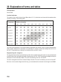
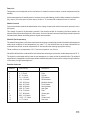
Explanation of terms and tables ............................................................................................................... 110
BidCoS™ wireless technology .................................................................................................................. 112
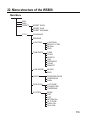
Menu structure of the WS888 .................................................................................................................... 113
Position table ............................................................................................................................................... 114
Declaration of Conformity (DOC) .............................................................................................................. 115
1. Introduction
Dear customer!
Thank you for purchasing this product.
The product meets the requirements of the current European and national guidelines.
We kindly request the user to follow the operating instructions to preserve this condition and to ensure safe operation!
These operating instructions belong to this product. It contains important information on how to put the product into
operation and how to operate it. Please take this into consideration when you pass the product on to third parties.
Keep these operating instructions for future reference!
All company names and product designations contained herein are trademarks of the respective owners. All rights
are reserved.
For technical questions, please contact:
Germany:
Phone: +49 9604 / 40 88 80
Fax. no.: +49 9604 / 40 88 48
e-mail:
[email protected]
Mon. to Thur. 8.00am to 4.30pm
Fri. 8.00am to 2.00pm
61
2. Prescribed use
The WS888 Multifunction Weather Station is a top-quality, highly comfortable universal weather measuring system
that can receive, process and display the data from up to eight remote wireless temperature and air humidity sensors
and one combination sensor over a range of up to 300 m (open-air range).
The weather station’s outdoor combination sensor collects the following weather data:
Temperature, air humidity, wind direction, wind speed, start of rainfall, amount of rain and sunshine duration.
The sensors for indoor temperature, indoor air humidity and air pressure are already integrated into the weather
station so that no external sensor is required.
The weather station has an excellent operating concept. It does not feature any of the usual control elements; rather
it is operated via a large touch screen and straightforward menus. The weather sensors are also quite easy to register.
The weather data of the combination sensor can be retrieved in real-time: just touch the corresponding display field
to start the data transfer (bidirectional wireless technology). The displayed data are thus always up to date.
In “Live Mode” the combination sensor can also be set to send its measured data in 2-second intervals for 20 seconds.
This allows you to track e.g. the wind direction and the wind speed in real-time for a period of 20 seconds.
The display can be lit permanently or at programmed times so that you can take your readings under nearly any
lighting conditions. In addition, the glass base and the transparent design frame of the station are lit.
The integrated DCF radio clock ensures the accurate time display and exact data acquisition.
The weather station has a large internal memory with capacity for 3000 data records in total making the weather
station suitable for long-time monitoring of the weather. The data records can be sent to your computer via USB port
where you can analyse and visualise the data using the “WeatherPro Edition 2007” analysis software that comes with
the weather station.
Please note!
The manual of the “WeatherPro Edition 2007” evaluation software is not a part of the weather station’s
manual. A separate manual is delivered with the software.
Please read all manuals carefully and completely before first starting the system to avoid malfunctions and
maloperations. Keep the manual for future reference.
You should pay special attention to the assembly and calibration instructions for the measuring sensors.
Any use other than the one described above damages the product. Moreover, it involves dangers such as e.g. shortcircuit, fire, electric shock, etc.
Please note all safety instructions and installation notes in this manual!
62
3. Meaning of the symbols
The lightning flash within a triangle is used to alert you to potential personal injury hazards such as
electric shock.
The icon with the exclamation mark in a triangle points towards particular dangers associated with the
handling, function or operation.
The “hand” symbol points out special tips and operating notes.
4. Delivered components
• Weather Station "WS888"
• Mains adapter for the weather station
• Pedestal and assembly material
• USB cable
• 3 batteries for the combination sensor
• Combination sensor with pedestal (delivered in parts)
• CD with driver and software
• The user’s manual for the ”Weather Professional” software is available on the supplied CD-ROM
• Manual for the WS888 Weather Station
63
5. Features and functions
The WS888 features the following display and operating functions:
Display of indoor temperature and air humidity
• Switchable to dewpoint display
• Memory for minimum and maximum temperature with time/date of occurrence
• Memory for minimum and maximum humidity with time/date of occurrence
• Comfort zone indicator
• Graphic history display for the last 24 hours
Displays one of max. 9 external sensors (temperature and humidity)
• Switchable: Dewpoint display or windchill display
• Memory for minimum and maximum temperature with time/date of occurrence
• Memory for minimum and maximum humidity with time/date of occurrence
• Graphic history display for the last 24 hours
• Low temperature alert
Display of wind speed and wind direction and variation range
• Available units: km/h, m/s, mph
• Memory for maximum wind force with time/date
• Display of wind direction with variation range as wind rose and numerical
• Windsock symbol to highlight different wind forces
Display of the amount of rainfall in mm, inch or l/m² for:
• Total amount since last deletion / last hour / current hour / last 24 hours /
Current 24 hours (acquisition of the hour: at xx:30 hours; day: at 7:30 am each day)
• Memory for the maximum amount per hour and per day
• Additional display for beginning rainfall (onsetting rain display)
Display of the barometric pressure development/trend indicator:
• Graphic display of the development over the last 24 hours
• Pressure trend indicator in five steps: rapidly rising, rising, constant, falling, rapidly falling
64
Symbol display of the weather forecast:
• rainy, cloudy, clear, sunny
Animated weather display
Do you remember the traditional weather houses where a little man with an umbrella comes out when the weather
is bad and his lightly clothed wife swings out when the weather is good? We have integrated this little character into
the WS888 weather station.
The little man is always dressed according to the present weather conditions so that the user can see at a glance
what to wear outdoors.
Besides outside temperature, air humidity, wind and rain, other factors are evaluated too. The weather forecast plays
an important role in this respect. Depending on the weather situation, the little man will appear dressed in many
different ways.
Display of time and date
• Integrated DCF77 radio clock, manual setting possible, daylight saving time/winter time changeover can be
deactivated
Display of sunrise and sunset
• Based on the individual site data to be entered, the calculation is possible between the -60° and +60° N latitude.
Moon phase display
• Display of the present moon phase: new moon, waxing moon, full moon, waning moon
Display of the sunshine hour total or for the present day
• Memory for minimum and maximum duration per day with time/date of occurrence
• Sun symbol appears when the sun is shining.
Data logger
• The data logger collects up to 3000 data records in settable intervals which can be downloaded to a PC via USB
port where the data can be analysed and graphed using the ”WeatherPro Edition 2007” software.
• When the data logger memory is almost full, you will be prompted to download the data.
Miscellaneous
• Easy, context-sensitive operation using straightforward menu structures
• Sound to acknowledge operations can be switched on and off.
• Desktop or wall mount possible
• Turn-on time of display lighting can be programmed.
• All important weather data are displayed simultaneously so that no operation of the device is required to detect
the weather situation.
65
• Several basic devices can be operated simultaneously so that the data of the sensors can be displayed in several
places at the same time.
• The outdoor sensor system of the "WS888" uses only wireless data transmission. The sensors can be set up or
installed in a distance of up to 300 m from the display console (depending on the local situation, see section
”Transmission range”).
66
6. Safety instructions
In the case of any damages which are caused due to the failure to observe these operating
instructions, the guarantee will expire. We do not assume any liability for resulting damages!
Nor do we assume liability for damage to property or personal injury, caused by improper use
or the failure to observe the safety instructions. The guarantee will expire in any such case!
Dear customer, the following safety instructions and danger warnings are not only to protect your well-being but also
to protect the device. Please read carefully through the following points:
• The unauthorized conversion and/or modification of the product is inadmissible because of safety
and approval reasons (CE). Do not open/disassemble it! There are no parts on the inside that need
to be adjusted or maintained by you.
Maintenance, setting jobs or repairs may only be carried out by a specialist/specialised workshop.
• Do not use this product in hospitals or medical institutions. Although the outdoor sensor emits only
relatively weak radio signals, these may lead to malfunction of life-supporting systems. The same
may be the case in other areas.
• The weather station is only suitable for dry indoor areas. Do not expose it to direct sunlight, heavy
heat, cold, dampness or wetness.
The combination sensor is suitable for exposed outdoor areas.
• The product is not a toy and should be kept out of reach of children! The product contains small parts
and glass (display) and batteries. Place the product in a way that it is out of reach of children.
• Do not leave packaging material unattended. It may become dangerous playing material for
children!
• Use the device only in moderate climate regions and not in tropical climate.
• When the product is brought from a cold into a warm room (e.g. during transport) condensation may
form. This could damage the product.
Leave the product until it has reached room temperature before using it. This can sometimes take
several hours.
• In industrial facilities, the safety regulations laid down by the professional trade associations for
electrical equipment and facilities must be adhered to.
• If the product is used at schools, training facilities, do-it-yourself and hobby workshops it should not
be handled unless supervised by trained, responsible personnel.
• Handle the product carefully and do not drop it, knocks, blows or even a fall from a low height can
damage it.
67
7. Notes on batteries and rechargeable batteries
• Keep batteries/storage batteries out of reach of children.
• Please observe correct polarity (positive/+ and negative/-) when inserting the accumulators/
batteries.
• Do not let batteries/rechargeable batteries lie around openly. There is a risk of batteries being
swallowed by children or pets. In such a case, seek immediate medical care.
• Leaking or damaged batteries/rechargeable batteries might cause acid burns when getting into
contact with skin, therefore, use suitable protective gloves.
• Make sure that batteries/storage batteries are not short-circuited or thrown into fire. They might
explode!
• Conventional batteries must not be re-charged. They might explode! Only charge rechargeable
batteries meant for this purpose.
• In the case of disuse for a longer period of time (e.g. storage) take out the inserted batteries/
rechargeable batteries. Old batteries/rechargeable batteries can leak and cause damages on the
product; loss of guarantee/warrantee!
• Always exchange the whole set of batteries/rechargeable batteries, only use batteries/rechargeable
batteries of the same type, by the same manufacturer and of the same charging state (don’t mix full
batteries with half-full or empty batteries/rechargeable batteries).
• Never mix batteries and storage batteries. Either use batteries or rechargeable batteries.
• For the environmentally friendly disposal of batteries and rechargeable batteries, please read the
chapter ”Disposal”.
Please note:
In general, it is possible to operate the product with rechargeable batteries.
However, due to the lower voltage of rechargeable batteries (rechargeable battery = 1.2V, battery =
1.5V) and the lower capacity there is a shorter operating time, the radio range can also be reduced.
When outdoor temperatures are low, rechargeable batteries are more sensitive than normal batteries.
This is why we especially recommend the use of high-quality alkaline batteries, to allow a long and safe
service life.
68
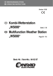
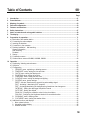
8. Display
1
2 3
5
4
6
26
25
7
8
24
23
9
22
21
20
10
19
12
11
7
18
13
14
17 16
15
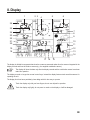
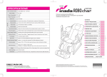
The display is divided into segments that show the numerous measured values from the sensors integrated in the
display console and from the outdoor sensors (e.g. the supplied combination sensor).
The display will show the data only after the display console and the combination sensor have been
taken into operation.
The display console no longer has normal control keys; instead the display features touch-sensitive sensors for
operating the unit.
The display front thus has a particularly clear design which is also easy to operate.
Touch the display only with your bare fingers, do not use objects for operation.
Touch the display only lightly; do not press too much on the display or it will be damaged.
69
1
Present indoor temperature with temperature trend
2
Display of the present wind direction (main wind direction)
3
Display of the variation range for changing winds
4
Wind speed display
5
Present air humidity of the selected outdoor sensor
6
Present temperature of the selected outdoor sensor with temperature trend and receive display
7
Display of the presently selected outdoor sensor (no display if combination sensor is selected).
8
Moon phase display
9
Display of the weather forecast (sunny, clear, cloudy, rainy)
10 Animated weather display with little man
11 Wind speed display (light, moderate, strong)
12 Warning against heavy weather
13 Low temperature alert
14 Menu bar
15 Air pressure trend display: rapidly rising, slightly rising, constant, slightly falling, rapidly falling; for more details
see ”Explanation of terms”
16 History display, referring always to the present value, see also page 26
17 Display of the current barometric pressure
18 Time and date display, radio tower symbol to indicate DCF77 reception
19 Display of sunrise and sunset times
20 Display of sunshine duration
21 Sun symbol appears when the sun is shining, otherwise the cloud symbol.
22 Display of the amount of rainfall
23 Display for starting rain
24 Current indoor humidity
25 Comfort zone indicator for displaying favourable/unfavourable climate
26 The symbol appears for the weather factor that is presently switched to the history display (indoor or outdoor
temperature). If the symbol does not appear, the air pressure history is displayed.
70
9. Preparation for operation
¨
¨
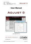
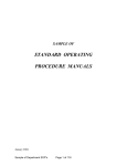
a) Back side of the weather station
+
-
+
-
+
-
+
-
A Eyebolt for wall mounting
B USB port
C Screw thread for foot pedestal
D Attachment points for pedestal
E Battery compartment
F Jack for external mains adapter
G Terminal for pedestal lighting
71
b) Connecting the mains adapter
The weather station is operated via the supplied mains adapter.
First plug the round barrel connector of the supplied mains adapter into the power supply jack on the back of the
display console and then connect the mains adapter to a 230V mains socket. Any inserted batteries are switched off
automatically.
The text „WAIT FOR TRANSMISSION“ appears in the lower part of the display (see Chapter 10 d),
Section 9). The weather station is attempting to contact the outdoor sensors (e.g. after power failure).
During this time the weather station can not be operated. This may take several minutes, please wait.
„MIN MAX RESET CFG“ is then displayed in the lower display section.
c) Inserting batteries
Remove the cover of the battery compartment and insert four AA batteries with correct polarity into the battery
compartment, see illustration in chapter 9 a).
The four AA batteries (1.5V, alkaline recommended) are for backup operation. Not all functions of the
weather station are available during battery-powered operation.
Close the battery compartment.
d) Connection to the computer
To connect the weather station to a computer, plug the supplied USB cable with the miniature USB connector to the
USB port of WS888.
The connector at the other end of the cable is connected to one of the computer’s USB ports.
e) Desktop installation / wall-mounting
X General
Before installing or wall-mounting the display console, make sure that the quality of the reception is good at the
desired location (measured data of the outdoor sensor(s)).
You should set up or install the display console as far away as possible from electric devices or metallic objects.
Moreover, the display console must be located as far away as possible from heaters or the measured values for the
inside temperature and indoor humidity will be useless.
For the same reason, you should not place the console into direct sunlight or next to a window or door (drafty).
X Wall mounting
There is an eyebolt on the back of the display console for mounting it to a suitable vertical wall.
Since the display console is rather heavy, it must be mounted securely. Depending on the structure of
your wall, use an appropriate nail or screw (with wall plug).
72
Be careful not to damage any electric cables, gas or water pipes because you could be injured
or killed as a result!
Hang the display console to the eyebolt. Before releasing the console, make sure that it is securely fastened to the
nail/screw.
If the display console is dropped, even from a low height, it is damaged and the warranty will be invalid.
X Pedestal
The pedestal consists of a foot and a glass pane with pre-assembled mount and integrated lighting. It can be used
to place the display console on a horizontal, level and sufficiently large surface.
Since display console is rather heavy, it can leave dents or scratches on furniture. The surface of
valuable furniture should therefore be protected by a suitable pad.
The connecting cables (USB cable, cable for pedestal lighting and the low-voltage cable of the power adapter) can
be laid in the pedestal. To mount, proceed as follows:
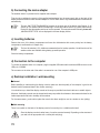
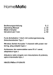
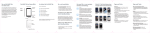
1. Remove the cover of the pedestal. To do so, unlatch it first at the top (1).
2. Then swing the cover down to lowest possible position (2). Now you can remove the cover from the pedestal.
1
2
73
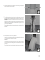
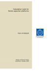
3. Latch the pedestal into the latch lug of the glass base and
place it on the two screw domes.
3
4. Screw the pedestal to the glass base using the supplied
wrench and two hexagon socket screws.
The lighting cable of the glass base must be laid as shown in
the picture so that it is not jammed.
4
5. Place the weather station at the latch lugs of the pedestal and
sway slightly until the screw domes fit neatly in the corresponding receptacles at the weather station.
Caution! Release the console only after you have screwed in
the two hexagon socket screws (see next step)!
Do not press on the display when you hold the console. Hold
it by the frame only!
5
74
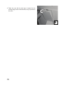
6. Screw the pedestal to the display console using the supplied
wrench and two socket screws.
6
7. The following picture shows how the cables are connected
and laid inside the pedestal. Make sure that the cables run in
the middle as shown in the picture so that the cover can close
properly.
Caution! The cables for the lighting of the glass base and the
USB cable can be plugged in one direction only! Do not use
force when plugging-in!
Excess lighting cable can be stowed away in a chamber of the
pedestal.
7
8. Now attach the cover of the pedestal:
Insert flat into the bottom guides in the pedestal (see also step
1), swing up until it latches into place.
Caution!
It should be easy to swing the cover up. If not, the cover does
not sit correctly in the bottom guides or the cables are not laid
correctly!
The picture shows how the cables should come out correctly.
8
75
9. Finally the cover with the latch lugs is inserted into the
corresponding cutouts of the cable duct, swing it up and latch
into place.
9
76
f) Startup
• After connecting the mains adapter, a short test of all display segments is started (all segments are displayed).
• An acoustic signal sounds next and the version number of the weather station is displayed.
• Then the indoor temperature and indoor humidity and the barometric pressure are displayed. The corresponding
sensors are installed directly in the display console.
The text „WAIT FOR TRANSMISSION“ appears in the lower part of the display (see Chapter 10 d),
Section 9). The weather station is attempting to contact the outdoor sensors (e.g. after power failure).
During this time the weather station can not be operated. This may take several minutes, please wait.
„MIN MAX RESET CFG“ is then displayed in the lower display section.
• Now you must install the external sensors.
g) Combination sensor
The combination sensor is delivered in parts and must be assembled before startup.
Take the wind vane and the white cylindrical enclosure of the vane, the combination sensor and the poles out of the
packing.
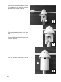
Mount the wind vane as follows:
1. Place the cylindrical enclosure of the wind vane on
the free pole end of the combination sensor support as shown in the picture.
Be careful not to damage the connector or twist the
cable.
¨
¨
The bevelled end of the cylindrical enclosure faces
downwards.
2. Guide the connector with the cable through the
base of the wind vane.
1
2
77
3. Plug the base into the pole and turn it so that
you can fasten the two screws in the bores
provided for that purpose in the pole.
3
¨
4. Connect the plug with the jacket in the wind
vane.
Make sure that the orientation is correct. Insert
the connector into the jacket until you can hear
it latching into place.
4
¨
¨
5. Push the cylindrical enclosure up as far as
possible and turn clockwise to lock it.
5
78
6. Assemble the poles that form the mast. The sensor carrier is plugged on the pole end marked with a sticker.
7. Set up the fully assembled sensor within the possible transmission range (up to 300 m in the open field, consider
damping by buildings). Select the location so that the sensor stands free and rain can drop directly into the rain
collector. You should also make sure that the wind measurement is not impaired by buildings, trees and similar
structures nearby.
A sunny location is possible since the temperature sensor is located in a shady and ventilated section
of the housing.
Push the mast with the compressed end first deep into the ground so that it stands firmly. People could be injured
or vehicles and objects could be damaged if the mast topples down.
When taking the station into operation for the first time, the tip of the wind vane must be oriented towards the North
to align the sensor. To do so, use some adhesive tape to fix the wind vane in this position at the housing.
8. Open the sensor housing by turning it counter clockwise. Then pull the housing
carefully downwards and remove it.
¨
¨
Button
9. Press the button above the battery compartment using a pointed
object (hold button down!) and insert three AA mignon batteries into
the battery compartment with the correct polarity. Release the button
and remove the adhesive tape from the wind vane.
10. Activate the receive mode at the display console, see also Chapter
10 a).
To do so, click the “CFG” button and then “NEXT”. “NEXT SENSOR”
is displayed. Press “ENTER”.
Press from NO 1" on upwards until you reach “NO 9” (this is the only
memory position where the combination sensor can be saved). This
memory position must not be occupied by any other sensor. If it is,
you may have to clear the memory, see also Chapter 10 a).
79
11. After activating the receive mode with the “ADD” button (“NO. 9 - SYNC” appears in the lower display section
of the console), you have approx. 15 seconds to press the recessed button on the combination sensor once
briefly. This registers the combination sensor at the receiving station and “USED” is displayed instead of
“SYNC”).
It may take several minutes until the combination sensor sends a new packet of measured data to the
display console where they data are displayed. Please wait during this time!
12. Close the housing again by pushing it up and turning it clockwise until
it latches into place.
¨
¨
h) Outdoor / indoor sensors ASH888, S888IA, ASH888I
Please refer to the corresponding manuals for information on how to assemble, address and take these sensors into
operation.
80
10. Operation
After you have installed the wireless sensors and started the display console, the data of the wireless sensor will not
at once appear on the display.
Since each sensor has an individual serial number, it must be registered separately at the display console.
This method has the advantage that only individually registered sensors are detected and no sensors of a third
system nearby; this is also the case when the system is restarted.
Please note:
If no entry field is touched for approx. 5 seconds when making entries in the menu bar, the station
automatically returns to the main menu (any settings you have made are applied). After an entry, you
should therefore wait until the main menu appears again.
This allows you also to leave a menu after each setting step.
Press only lightly on the entry fields, do not apply too much force. Do not press or knock on the display
with objects, nor with your fingernail!
Your fingers should be dry and clean when you touch the display (a special cleaning mode can be
activated to clean the display without triggering functions).
When you remain on a setting field with your finger, the values in the menus can be configured more
quickly, they will run automatically and you do not have to tap the display repeatedly.
a) Registering / deleting external sensor
You can register up to 9 external sensors. Memory position 9 is reserved for the combination sensor; all other sensors
occupy the memory positions 1 to 8.
To unambiguously assign the sensors when using several sensors of the types ASH888, ASH888I and S888IA, we
recommend to remove the batteries of all sensors first.
X Registration
• Touch the "CFG" field in the menu line. You will see:
NEXT SENSOR
ENTER
• Touch "NEXT" and you will see:
NEXT SENSOR
ENTER
• Touch "ENTER" and you will see:
SENSOR NO 1
ADD DEL
81
• Touch "SENSOR" repeatedly to select the memory position where to save the desired sensor.
Please bear in mind that the combination sensor can only be saved to memory position 9.
Tips for taking sensors into operation:
To safely take sensors into service, you can activate them first near the weather station. But the distance
between sensor and weather station must not be less than 1 m to avoid interference.
• Select "ADD" and the display will read (example for sensor 9: combination sensor):
SENSOR NO 9 - - SYNC ADD DEL
To synchronise the sensor, press its synchronisation button within the next 15 seconds. The text „USED“ is
displayed instead of „SYNC“; this signals that the sensor has been found and saved successfully.
The data of the combination sensor appear automatically after several minutes in the corresponding display fields
(when receiving a data packet). The data of the remaining sensors will be displayed after selecting the memory
position (“Sensor” field) in the OUTDOOR display segment.
X Identification of occupied memory positions
Memory spaces which are already occupied are highlighted by "USED" after the memory space number.
This information does, however, not indicate whether the corresponding sensor is really active.
This can only be recognized by missing or not up-to-date data during sensor selection and by the active
radio tower signal in the "OUTDOOR" field.
X Deleting a sensor assignment
The serial number of a sensor can also be deleted from the sensor memory if required.
• First proceed as described at “Registration”, select the desired sensor and then apply "DEL" (=delete) instead of
"ADD".
• The "USED" supplement after the sensor number is deleted and the memory space becomes available for
registering a new sensor.
82
b) Operation
Since all relevant data appear simultaneously on the display, the operation merely involves selecting additional
sensors or additional weather data by lightly touching the corresponding display fields.
The display is divided into the display section and the menu line. During normal operation (main menu displayed)
the menu line reads the followings text fields:
MIN MAX
RESET
CFG
X Touching the display
Lightly touch the corresponding segments of the display field (upper part of the display) to access the following
functions:
INDOOR
Switching between temperature and dewpoint display ("DEWPOINT")
OUTDOOR
Switching between temperature, dewpoint and windchill display.
HUMIDITY
No function
SENSOR
Switching between the external sensors:
Display “1” to “8”: ASH888, ASH888I, S888IA
No display: combination sensor
RAIN
switching between the total rain quantity since the last reset (“total”), current hour
(“current 1h”), last hour (“1h”), current day (“current 24h”) and last day (“24h”).
Acquisition of the hour: at xx:30 hours; day: at 7:30 am
SUNSHINE DURATION
Switching between sunshine duration of the present day (“h/day”) and total sunshine
duration since last reset (“h”)
TIME/DATE
No function
WIND
Switching the numerical display between wind speed in km/h, m/s, mph and wind
direction in degrees.
AIR PRESSURE
Switching the barometric pressure display between the local measure pressure (“absolute”) and the pressure calculated for sea level (“relative”)
HISTORY
Switching the history display of the last 24 hours between air pressure, indoor
temperature and outdoor temperature (of the displayed sensor)
Weather symbol field
No function
83
X Functions of the main menu
MIN
Displaying the minimum values
Touch the "MIN" field to show the minimum values of the corresponding data on the display field. Touch
the corresponding field (temperature, air pressure etc.) to show the associated time stamp (date, time)
right in the menu line when the extreme value occurred.
Touch again "MIN" to return to the main menu.
MAX
Displaying the maximum values
Touch the "MAX" field to show the maximum values of the corresponding data on the display field. Touch
the corresponding field (temperature, air pressure etc.) to show the associated time stamp (date, time)
right in the menu line when the extreme value occurred.
Touch again "MAX" to return to the main menu.
RESET
Resetting certain values
This menu has three submenus for resetting the accumulated sunshine duration (SUN), the amount of
rainfall (RAIN) or the MIN-MAX memory (MIN-MAX).
Apply the "RESET" field. The RESET menu appears:
RESET
RAIN
OK
Touch the "RESET" field repeatedly to select the desired option on the left and then apply "OK". The
selected data are now deleted and the main menu is displayed again.
If you do not wish to delete data, wait until the main menu reappears. The data is then not deleted.
CFG
Opening the configuration menu
This menu allows you to enter e.g. the time and date, register sensors and many more settings which
will be explained in the following chapter.
84
c) Configuration
The weather station is operational immediately after it is taken into operation; additional settings of the basic functions
are not necessary (except moon phase, sunset and sunrise indicator, date, clock, min-max display).
But one additional configuration is necessary to use the additional and time-related functions.
• Touch "CFG" to open the configuration menu.
MIN MAX
RESET
CFG
• Touch "NEXT" repeatedly to go to the corresponding next main menu item of the configuration menu. A menu
overview in the Appendix shows how to quickly access individual menus.
X 1. "SENSOR" menu, registering or deleting sensors
See chapter 11 a).
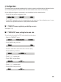
X 2. "TIME/DATE" menu, setting the time and date
This setting is only required if no DCF synchronisation has taken place.
• Select the "TIME/DATE" menu:
NEXT
TIME/DATE
ENTER
• Touch "ENTER" and you will see:
TIME
24H
• Touch the "24H" field to select either 12h or 24h time display.
• Touch "TIME" and you will see:
YEAR
+ 2006 -
• Touch "+" or "-" to set the year.
• Touch "YEAR" and you will see:
MONTH
+ 07 -
• Touch "+" or "-" to set the month.
• Touch "MONTH" and you will see:
DAY
+ 01 -
85
• Touch "+" or "-" to set the day date.
• Touch "DAY" and you will see:
WEEKDAY
+ MON -
• Touch "+" or "-" to set the weekday.
• Touch "WEEKDAY" and you will see:
HOUR
+ 01 -
• Touch "+" or "-" to set the hour.
• Touch "HOUR" and you will see:
MINUTE
+ 01 -
• Touch "+" or "-" to set the minute.
• Wait a few seconds and the display shows the time and date, sunrise and sunset time for the factory setting (52.5/
13.4°, Berlin) and the current moon phase.
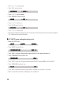
X 3. "UNITS" menu, setting the display units
• Select the "UNITS" menu:
NEXT
UNITS
ENTER
• Touch "ENTER" and you will see:
TEMPERATURE
DEG C
• Touch "DEG" to switch the display between degrees Celsius (C) and degrees Fahrenheit (F).
• Touch "TEMPERATURE" and you will see:
PRESSURE
HPA
• Touch "HPA" to switch the air pressure display between hPa (HPA), mmHg (MMHG) und inHg (INHG)
• Touch "PRESSURE" and you will see:
RAIN
MM
• Touch "MM" to switch between rain quantity display in mm (MM), inches (INCH) or l/m² (L/M2).
• Wait a few seconds and the data are displayed in the selected units.
86
X 4. "POSITION" menu, setting the position
The position data of the installation site of the weather station is required for calculating the sunrise and sunset times.
You can enter between –60.0° and +60.0° latitude.
There are different ways to determine your position:
• The Appendix contains a list with the coordinates of numerous German cities. You can select a city in your vicinity
and enter its coordinates.
• If you have GPS, e.g. in your car or a mobile unit, you can take over the coordinates indicated there and so obtain
the exact position.
• Accurate coordinates can also be found on the internet. There are various sites about navigation.
After you have determined your position coordinates, enter the data into the weather station as follows:
• Select the "POSITION" menu:
NEXT
POSITION
ENTER
• Touch "ENTER" and you will see:
LATITUDE
+ 52.4 -
• Touch "+" or "-" to set the latitude.
• Touch "LATITUDE" and you will see:
LONGITUDE
+ 007.8 -
• Touch "+" or "-" to set the longitude.
• Wait a few seconds and the corrected data for sunrise and sunset are displayed.
Please bear in mind that the sunrise and sunset times are really only accurate at the sea or in a
completely plane landscape.
Mountains, high woods etc. can considerably shorten the real days.
Even if the location is ideal, it is possible that the data differ by a few minutes, since an approximation
formula is used to calculate these times.
87
X 5. "TIMEZONE" menu, setting the time zone
The time zone is required for calculating the sunrise and sunset times. You must enter the present offset to the UTC
(Coordinated Universal Time) here.
For Germany the following values apply:
Daylight saving time:
+2 hours
Winter time:
+1 hour
Proceed as follows:
• Select the "TIMEZONE" menu:
NEXT
TIMEZONE
ENTER
• Touch "ENTER" and you will see:
TIMEZONE
+ 01 -
• Touch "+" or "-" to set the time zone.
• Wait a few seconds and the corrected data for sunrise and sunset are displayed.
88
X 6. "LIGHTING" menu, setting the background lighting
This menu allows you to set the switch-on time for the background lighting which switches on automatically upon
touching the screen and switches off again after a settable time. You can set either OFF (lighting always off), times
between 5 seconds and 10 minutes and permanent light (ON). And you can specify times during which the lighting
is to be permanently activated.
You can also activate/deactivate the automatic adjustment to the ambient lighting conditions so that the display can
be read optimally under nearly any light conditions.
The background lighting can only be used if the weather station is mains operated (not when it is batterypowered!).
• Select the "LIGHTING" menu:
NEXT
LIGHTING
ENTER
• Touch "ENTER" and you will see:
LIGHTING
+ 10 SEC -
• Touch "+" or "-" to set the switch-on time.
• Touch "LIGHTING" and you will see:
BRIGHT CTRL
ON
• Touch "ON" to switch the display between automatic brightness control active (ON) or deactivated (OFF).
• Touch "BRIGHT CTRL" and you will see:
BEGIN
+ 16.00 -
• Touch "+" or "-" to set the switch-on time for the lighting (permanent lighting).
• Touch "BEGIN" and you will see:
END
+ 23.45 -
• Touch "+" or "-" to set the switch-off time for the lighting (permanent lighting).
• Wait a few seconds and the station will return to normal mode and your settings will be activated.
89
X 7. "SYSTEM" menu, system settings
This menu allows you to make settings for the automatic daylight-saving time/winter time changeover ("DST", see
also Appendix), activate the acoustic key acknowledge signal ("BEEP"), activate the DCF radio clock ("DCF"), specify
the data acquisition interval of the data logger ("INTERVAL"), enter the altitude ("ALTITUDE") and calibrate the rain
sensor ("RAIN CAL") and configure the brightness threshold for the sunshine duration ("SUN CAL").
Z "BEEP": Activate / deactivate the acoustic key acknowledge signal
• Select the "SYSTEM" menu:
NEXT
SYSTEM
ENTER
• Touch "ENTER" and you will see:
BEEP
ON
• Touch "ON" to switch the key acknowledge beep ON or OFF.
Z "DCF": Activating / deactivating DCF reception
• Select the "SYSTEM" menu and (via "BEEP") the option "DCF":
DCF
ON
• Touch "ON" to switch the DCF reception ON or OFF.
Z "DST": Activating/deactivating the daylight-saving time/winter time changeover
• Select the "SYSTEM" menu and (via "BEEP" and "DCF") the option "DST":
DST
ON
• Touch "ON" to switch the automatic daylight saving time changeover ON or OFF.
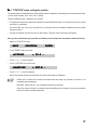
Z "INTERVAL": Setting the data logger acquisition interval
The data logger acquisition interval specifies the intervals in which the integrated data logger records the datasets.
The shorter you select the intervals, the shorter are the recording time but the recording becomes more detailed. If
the intervals are longer, the possible recording time increases but the resolution of the weather data decreases.
The acquisition interval can also be set from the computer.
• Select the "SYSTEM" menu and here (via "BEEP", "DCF" and "DST") the option "INTERVAL":
INTERVALL
90
+ 05 -
• Touch "+" or "-" to set the interval time (OFF = data logger deactivated, 5 minutes to 60 minutes). Below you will
find some examples of how the interval time and the recording time relate:
Interval time
Max. recording time
5 minutes
10 minutes
30 minutes
60 minutes
10.4 days (250 hours)
20.8 days (500 hours)
62.5 days (1500 hours)
125 days (3000 hours)
Z "ALTITUDE": Setting the altitude
The altitude is needed for calculating the relative air pressure related to sea level compared to the absolute air
pressure at your location. This relative value is an important reference quantity to be able to correctly interpret
weather forecasts referring to the relative air pressure.
• Select the "SYSTEM" menu and here (via "BEEP", "DCF", "DST" and "INTERVAL") the option "ALTITUDE":
ALTITUDE
ENTER
• Touch "ENTER" and you will see:
ALTITUDE
+ 0000 -
• Touch "+" or "-" to set the geographic altitude of your location above sea level in meters.
• Wait a few seconds and the corrected data for the relative air pressure are displayed. The value can also be
entered via the supplied software.
Z "RAIN CAL": Entering the calibration value for the rain collector
The rain measuring gauge is extremely accurate upon delivery; therefore it is normally not necessary to calibrate it.
The calibration value must first be determined during normal mode as described in the chapter “Calibration of the
rain collector”.
• Select the "SYSTEM" menu and here (via "BEEP", "DCF", "DST", "INTERVAL" and "ALTITUDE") the option
"RAIN CAL":
RAIN CAL
ENTER
• Touch "ENTER" and you will see:
RAIN CAL
+ 295 -
• Touch "+" or "-" to set the previously calculated value.
• Wait a few seconds until the station returns to the normal display. The value can also be entered via the supplied
software.
91
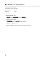
Z "SUN CAL": Configuring the brightness threshold for sunshine duration
The WS888 weather station measures the sunshine duration with its combination sensor. The threshold value is set
at the display console and is then transmitted to the combination sensor. The sensor then evaluates the data:
Measured brightness greater than threshold
¨
sun is shining
Measured brightness smaller than threshold
¨
sun is not shining
The brightness threshold can be set individually by the user to adjust the sensor to the local conditions. The threshold
value should be defined when the sun begins or stops to shine to make conclusions from the present brightness value
to the threshold.
• Select the "SYSTEM" menu and here (via "BEEP", "DCF", "DST", "INTERVAL", "ALTITUDE" and "RAIN CAL")
the option "SUN CAL":
SUN CAL
ENTER
• Touch "ENTER" and you will see:
SUN CAL
131
+ 085 -
The medium display range (131 in the above example) shows the present brightness value.
The direct conversion into lux is not possible.
The right display area (085 in the above example) shows the adjusted threshold value.
• Touch "+" or "-" to set the threshold value. The setting range is from 0 to 255.
• Wait a few seconds until the station resumes normal mode.
92
X 8. "CLEANING" menu, cleaning mode
A cleaning mode is available in which all touch fields are locked for 20 seconds so that no functions are triggered when
wiping the display.
The display becomes dirty during use and needs to be wiped clean from time to time using a clean, soft and dry linen.
A glasses cleaning cloth is well suited for this purpose. Do not use cleaning agents which can destroy
the touch-sensitive display!
Do not press too much on the display when wiping it clean.
• Select the "CLEANING" menu:
NEXT
CLEANING
ENTER
• Touch "ENTER" and you will see:
CLEANING
START
• Touch "START" and you will see:
CLEANING
WAIT
• Now you can clean the display. The tactile sensors in the display are deactivated. After 20 seconds the normal
display reappears and the tactile sensors are reactivated.
If you have not yet finished cleaning the display, you can start the cleaning mode again.
93
X 9. "LIVE MODE" menu, starting the weather ticker
The live mode is started by applying an additional touch field which prompts the combination sensor to send its data
in 2-second intervals during a period of 20 seconds. This allows you to track e.g. the current weather conditions e.g.
the wind direction and the wind speed in real-time for a period of 20 seconds.
In LIVE MODE the combination sensor consumes more power because it switches to reception more
frequently. This reduces the battery lifetime.
You can therefore set a time limit for this mode in the LIVE MODE menu. During that time, the additional touch field
REQ will appear in the main menu line which triggers the live weather ticker.
• Select the "LIVE MODE" menu:
NEXT
LIVE MODE
ENTER
• Touch "ENTER" and you will see:
BEGIN
+ 16.00 -
• Touch "+" or "-" to set the switch-on time for the LIVE MODE.
• Touch "BEGIN" and you will see:
END
+ 23.45 -
• Touch "+" or "-" to set the switch-off time for the LIVE MODE.
• Wait a few seconds and the station will return to normal mode and your settings will be activated.
• The following message appears in the menu line while the data are transmitted to the combination sensor:
WAIT FOR TRANSMISSION
While this message is displayed, the weather station can not be operated.
• The additional touch field "REQ" is displayed on the menu when the LIVE MODE is activated for requesting the
data:
MIN MAX
94
RESET
REQ
CFG
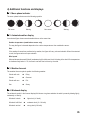
d) Additional functions and displays
X 1. Moon phase indicator
The moon phase indicator uses the following symbols:
Full moon
Waning
New moon
Waxing
X 2. Animated weather display
An animated figure shows several weather factors at the same time:
Outdoor temperature (combination sensor only)
The way the figure is dressed depends on the outdoor temperature at the combination sensor.
Rain
If the weather forecast has predicted rainy weather, the figure will carry a closed umbrella. When it has started
to rain, the figure carries an open umbrella.
Wind speed
When wind speeds exceed 20 km/h (moderate wind), the little man’s hair is blowing in the wind. If the temperature
is simultaneously below 14°C, the man’s scarf will also be blown by the wind.
X 3. Weather forecast
The weather forecast symbols predict the following weather:
Clouds with rain
¨
Rainy
Clouds
¨
Overcast
Clouds with sun
¨
Fair
Sun
¨
Sunny
X 4. Windsock display
The windsock symbol in the forecast display field shows at a glance whether the wind is presently blowing lightly,
moderately or heavily.
Windsock is slack
¨
light wind (<10 km/h)
Windsock half lifted
¨
moderate wind (10...20 km/h)
Windsock vertical
¨
strong wind (>20 km/h)
95
X 5. Onsetting rain display
The onset of rain is reported to the console with the next wireless data transmission and symbolised by a rain cloud
in the "RAIN" field and by the open umbrella of the little man.
X 6. Comfort indicator
The comfort indicator (
☺) reflects the room climate (relationship between temperature and air humidity). You
can find a value table for the display ranges in the Appendix.
X 7. History
The bar chart shows the development of the barometric pressure or of the outdoor and indoor temperature over the
last 24 hours. The individual bars do not represent an absolute value here; rather they show the difference to the
current measured value (0h bar). This point of reference is always located in the center (4 bars) to see at a glance
what the trend is.
X 8. Data memory
The following message appears in the menu line when the data memory is nearly full:
MEMORY ALMOST FULL
OK
Touch OK to confirm the message and download the collected data to your computer.
X 9. Data transmission to the combination sensor ("WAIT FOR TRANSMISSION")
If the menu line reads "WAIT FOR TRANSMISSION", the weather station is currently busy sending data to the
combination sensor, e.g. when activating the Live Mode or the configuration data of the sunshine duration.
This process may take up to several minutes. During this time the weather station can not be operated.
X 10. Temperature trend display
An arrow to the right of the temperature displays in the "INDOOR" and "OUTDOOR" display fields indicates the
temperature trend during the last transmission interval. An increase in temperature is indicated by an arrow pointing
upwards and a decrease by a downward pointing arrow.
96
X 11. Sensor status display
The sensor status is indicated by a small radio tower symbol in the "OUTDOOR" display field.
Radio tower appears constantly
¨
Data from the sensor are received correctly.
Radio tower is blinking
¨
No data have been received from the sensor for 40 minutes.
No radio tower symbol
¨
The sensor is not there or it is permanently faulted or defective.
X 12. DCF77 time signal
• Directly after it has been switched on, the weather station makes an attempt to receive the DCF77 time signal in
order to set its clock automatically.
• If the weather station receives the time signal, time and date will be updated automatically and a small radio tower
icon appears between them.
• Every day at 4:00 am the weather station starts a synchronisation attempt with the DCF77 transmitter.
• If no DCF77 signal is received, the internal clock operates as a quartz clock.
• DCF77 reception can be deactivated if required (see menu "SYSTEM/DCF").
X 13. Warning against heavy weather
A danger sign will appear in the weather forecast display field if the barometric pressure drops sharply within a short
time. This could be a sign of a storm or thunderstorm approaching.
X 14. Low-temperature alert
A snowflake will appear in the weather forecast display field if the measured temperature at the combination sensor
falls below +4°C .
97
11. Battery replacement
a) Display console
If the empty battery symbol (
9 a) or 9 c).
) appears, all batteries have to be replaced by new ones as described in chapter
Replace always all four batteries and insert only high-quality alkaline batteries. The weather station
should be connected to the power supply when changing batteries to avoid data loss.
Please note:
If no power adapter is connected, the data memory will be cleared when changing the batteries and all
measured values will be deleted.
b) Wireless sensors
The batteries in these sensors have a life span of up to 2 years (alkaline batteries). They must be changed if a battery
empty symbol (
) appears in the OUTDOOR sensor field when selecting the corresponding sensor.
The batteries of the combination sensor are changed as described in chapter 9 g). For the other sensors, please refer
to their manuals.
98
12. Troubleshooting notes
Possible malfunctions can hinder the correct display of the measured values:
• No signal received
¨ The distance between transmitter and receiver is too great or too small (< 1 m). Reduce or increase the
distance between transmitter and receiver.
¨ Strongly shielding materials are between the transmitter and the receiver (thick walls, reinforced concrete
etc.). Select a different location for transmitter or receiver. See also the chapter “Transmission range” in this
context.
¨ The batteries of the sensors are empty, change the batteries.
¨ The transmitter is superimposed by interfering transmitters (radio equipment, wireless headphones or
speakers). Eliminate the source of the interference or select a different location for transmitter and receiver.
If wireless headphones, wireless baby monitors or similar devices are operated at 868 MHz, they are usually
switched on for a limited time only, interferences will therefore occur only occasionally.
It may be possible to operate these devices on a different frequency so that they no longer interfere with the
weather station.
• The wireless sensor interferes with other devices in the 868 MHz range
¨ The transmissions of the wireless outdoor sensor can temporarily (every 2 to 3 minutes for approx. 100 ms)
interfere with other device operating on the same channel.
In some wireless headphones, for instance, this becomes evident as a short noise.
Select a different transmission/reception frequency for the device you are using (e.g. wireless headphones)
if possible.
Additional notes for startup and troubleshooting
Try to turn the weather station a bit, place it in some distance from electrical motors, electrical machines television
sets, computer screens and large metal surfaces.
For an easier start you can also set up the sensor near the display console (at least 1 m distance). Here you can first
check that the sensor correctly sends its data and thus the function of the weather station.
The sensor must be properly registered at the weather station or their data will not be displayed.
99
13. Transmission range
The transmission range in the open field, i.e. there is visual contact between transmitter and receiver, is 300 m under
optimal conditions. Walls and even reinforced steel structures can be penetrated but this reduces the range
accordingly.
A reduced transmission range can be due to the following factors:
• High frequency interferences of all sorts
• Any kind of housing or vegetation
• The distance of the transmitter or receiver to conducting surfaces or objects (also the human body or the ground)
influences the emission characteristics and thus the range.
• Broadband interferences in urban areas can reach levels that decrease the signal—to-noise ratio over the entire
frequency band thus reducing the range.
• Devices with neighbouring operation frequencies can equally influence the receiver.
• Poorly screened or openly operated computers can emit into the receiver and reduce the range.
100
Since local conditions vary from site to site, a definite range cannot be guaranteed.
However, normally in a detached house trouble-free operation is possible. When the base station
doesn’t receive any data from one or several sensors (despite new batteries), reduce the distance
between the outdoor sensor(s) and base station, change the installation site.
14. Maintenance and care
a) General information
Maintenance or repairs may only be carried out by qualified persons or a specialist workshop.
Improper work invalidates not only the guarantee/warrantee but also the license (CE). It also involves
the risk of a fatal electric shock.
This product does not contain any serviceable parts. Therefore, do not open it (except for those operations described
in this manual e.g. assembly, inserting or changing the batteries etc.).
Regularly check the technical safety of the product e.g. for damage of the housing.
If there is any reason to believe that safe operation has become impossible, put the device out of operation and secure
it against any unintended operation. Remove the batteries, disconnect the weather station from the mains adapter
and unplug the mains adapter from the mains socket.
It can be assumed that safe operation is no longer possible if
• the device shows visible damages,
• the device is no longer functional and
• after it was stored under unfavourable conditions for a long period of time or
• after it was exposed to extraordinary stress caused by transport.
b) Cleaning the display console
Before cleaning the display, activate the Cleaning Mode at the display console as described in chapter 11 c). When
you clean the display without using the cleaning mode, you can inadvertently trigger functions which can lead to
undesired results.
To clean the display, use only a soft, clean and dry cloth. A glasses cleaning cloth is well suited for this
purpose.
Do not use rough cloths; never use liquid cleansers! This can be aggressive on the touch-sensitive
surface of the display.
Dust can be removed using a clean, soft brush and a vacuum cleaner.
Do not press too much on the display when wiping it clean.
101
c) Cleaning the outdoor sensors
Dirt on the outdoor sensors can be removed with a damp cloth.
Never use aggressive cleansing agents or other chemical solvents since they can damage the surface
of the housing or even impair operation.
Do not hose down the outdoor sensors because the outdoor sensors are only protected against rain
that comes from above and not against a jet of water from the side or from below.
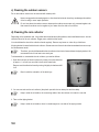
d) Cleaning the rain collector
Depending on the installation site, it is possible that the wind carries dirt particles, sand, small branches etc. into the
collection funnel of the rain collector. Bigger parts could block the funnel.
You should therefore check the collection funnel regularly. Remove any leaves or other dirt you find there.
A tipping bucket is located inside the rain collector. Greater amounts of sand or dust that accumulate here can corrupt
the measurement result.
Therefore, you should disassemble the rain collector from time to time and clean the tipping bucket. We
recommend to do this at least once each year.
To disassemble or re-assemble the rain collector, proceed as follows:
Remove next the collection funnel by turning it slightly clockwise and lift
it off.
3
¨
¨
1. Open the lower part of the rain collector by turning it counter clockwise
by approx. 1 cm until you can slide it down at the metal tube.
4
Bear in mind the orientation of the latch lugs.
1
¨
¨
2
2. You can now take out the rain collector (the plastic part with the two brass pins and the cable).
Keep in mind the orientation: the connecting cable of the rain collector is located on one side.
3. Take out the tipping bucket.
102
Keep in mind the orientation: there is a small magnet on one side of the tipping bucket.
4. Now clean the components of the rain collector. Clean also the drain hole in the plastic lower part of the rain
collector that you slid down the metal tube.
5. To reassemble the rain collector, insert first the tipping
bucket into its holder.
The magnet of the tipping bucket must be on the
side that faces the cable.
The two lower trapezoid pins must be properly
inserted into the bottom section of the holder.
In that way the tipping bucket will move smoothly.
6. Insert the rain collector into its mount. It will automatically
hold the tipping bucket as well.
Only one orientation is correct.
The cable of the rain collector and the magnet of
the tipping bucket must be on the same side.
The plastic lug on the other side must be properly
inserted into the holder!
1
¨4
¨
2
¨
Close the bottom part of the rain collector.
¨
7. Place the collection funnel back on the sensor carrier and turn it counter
clockwise to lock it.
3
103
e) Calibrating the rain collector
The rainfall measuring gauge is extremely accurate upon delivery; therefore it is normally not necessary
to calibrate it.
A calibration is only necessary if utmost accuracy is required.
The calibration process is rather long (at least 10 minutes) and must be carried out with extreme
diligence and care or the accuracy will be poorer than before.
Before starting the calibration of the rain collector, reset the rain quantity at the display console to zero
(total rain display reads zero) in normal display mode.
And the unit for the rain quantity must be set to “mm” or “l/m²” for the calibration. Set the display unit
correctly.
Make also sure that the rain collector is clean (collection funnel, drain hole, tipping bucket) and that the
tipping bucket is dry.
To accurately calibrate the unit, then proceed as follows:
1. Pour in 100 ml of water very slowly into the collection funnel of the rain collector over a period of 10 minutes.
Caution!
If you pour in the water too quickly, the measuring result will become inaccurate. Pour in the water so
slowly that the water is never standing in the funnel.
Please remember that even in heavy rain only a few raindrops will fall into the opening of the rain
collector.
2. The total quantity should now be 6.5 l/m².
3. If a different value is displayed, the so-called tipping value must be recalculated as follows:
6.5 x present tipping value
New tipping value =
Actual value (display after filling in the water)
4. Now enter the new tipping value in the configuration menu (RAIN CAL system menu). It is indicated in ml/tipping
scoop.
104
The ex-factory setting is 295 ml/tipping scoop.
15. Handling
Take note of all the safety instructions in these operating instructions!
a) General information
The product must not be opened or disassembled (except those operations described in this manual for inserting
batteries, assembling or cleaning the rain collector).
Even a fall from a low height can damage the product.
b) Display console
• Avoid the following adverse environmental conditions when setting up and operating the display console:
-
moistness or too high air humidity
extreme cold or hot temperatures
direct sunlight
dust or flammable gases, fumes or solvents
strong vibrations
strong magnetic fields such as exist near machines or loudspeakers
• Never use the display console and the mains adapter immediately after it has been brought from a cold room into
a warm room. Condensation water that forms might destroy the product.
The mains adapter also involves the risk of an electric shock!
Wait until the display console and the mains adapter have reached room temperature. This can take several hours.
• The installation site should be chosen so that the display console has a firm stand and cannot fall down. Because
of the heavy weight there is a risk of injuries.
Select an even and sufficiently large surface for setting up the display console.
• Valuable or scratch sensitive furniture surfaces should be protected from damage with suitable covers before
placing the display console on them.
105
c) Combination sensor
The supplied combination sensor can be used in exposed outdoor areas.
But do not hose down the combination sensor with a garden hose or similar equipment.
Select an installation site where the sensor can not be knocked over by children. Do not erect the combination sensor
near vehicles, glass doors or windows!
16. Disposal
a) General information
At the end of its useful life dispose of the product according to the relevant statutory regulations!
b) Batteries and rechargeable batteries
The end user is legally obliged (battery regulation) to return used batteries and rechargeable batteries. Do not throw
used batteries into the household waste!
Batteries/storage batteries containing harmful substances are marked with the following symbols which
point out that the disposal via the household rubbish is prohibited. The designations for the respective
hazardous heavy metals are: Cd=cadmium, Hg=mercury, Pb=lead (name on battery/rechargeable
battery, e.g. under the rubbish bin icons on the left).
You can return your exhausted batteries/rechargeable batteries free of charge to any authorized
disposal station in your area, in our stores or in any other store where batteries/rechargeable batteries
are sold.
Thus, you comply with your legal obligations and make your contribution to environmental protection.
106
17. Connection to the computer
The WS888 can be connected to a computer via USB (Windows 2000, Windows XP or higher).
The measured values can then be downloaded to the computer and the data can be analysed.
Please observe the software manual.
The “WeatherPro Edition 2007” software has the following system requirements:
• Windows 2000/XP operating system
• Min. 1GHz frequency
• Min. 256 MB RAM
• Required hard disk space for the program: approx. 150 MB
• Required space for the database: approx. 100 MB
• The hard disk drive must be formatted with the NTFS file system (FAT32 is not possible for the database)
• The Windows installer service must be installed (standard Windows options).
• One free USB port
Proceed as follows:
• Connect the weather station via the USB cable to a free USB port of the computer.
• The computer will detect the new USB device after a short time and ask for a driver. The installation wizard opens.
• Insert the supplied CD into the correct drive of your computer and wait until the Welcome screen appears.
• In the Installation Wizard select the option “Search automatically”.
• Follow the instructions of the Installation Wizard until you have finished installing the drivers.
• Go to the “WeatherPro Edition 2007 Setup” which describes the four setup steps. Begin at step 2.
• Follow the instructions step by step until the installation is finished. Then you can start “WeatherPro Edition 2007”
from the Desktop or the program menu.
• You will find the program description in the help menu at “Manual”.
107
18. Firmware update
A firmware update of the main controller of the WS888 can be performed using the supplied software via the USB
port.
Start the update program in “WeatherPro Edition 2007” (“Options” menu, “Firmware update” menu item) and follow
the instructions by the program.
Note:
If you have started the update process by mistake, you can abort it at any time until step 5.
If the update mode has also been activated at the device according to the instructions of the software,
the weather station must be disconnected from the USB port and the mains socket for a few seconds
and the batteries must be removed. The device function is not affected by this; after restart it will operate
with the firmware version used so far.
108
19. Technical data
Measuring interval of outdoor sensors: .......................................................................................................... 2-3 min
Measuring interval of indoor sensor (temperature, air humidity): .................................................................... 3 min
Measuring interval of barometric pressure: ..................................................................................................... 15 min
Transmission frequency: ......................................................................................................................... 868.30 MHz
Free field range: ....................................................................................................................................... max. 300 m
Indoor temperature range: ................................................................................................................... 0°C to +60°C
Resolution: ......................................................................................................................................................... 0.1°C
Accuracy: .............................................................................................................................. ±1°C (+15°C to +40°C)
Outdoor temperature range (combination sensor): ................................................................... -19.9°C to +79.9°C
Resolution: ......................................................................................................................................................... 0.1°C
Accuracy: ........................................................................................................................... ±0.8°C (+10°C to +40°C)
Measuring range of rel. humidity (indoor/outdoor): ....................................................................... 1% rH to 99% rH
Resolution: ......................................................................................................................................................... 1% rH
Accuracy: ................................................................................................................................ ±5% rH (30 to 70% rH)
Rain quantity display: ............................................................................................................................. 0 to 999 mm
Evaluation interval: .............................................................................................................. last hour: at xx:30 hours
............................................................................................................................................................ day: at 7:30 am
Resolution: ............................................................................................................................ up to 100 mm: <0.3 mm
................................................................................................................................................... above 100 mm: 1mm
Wind speed: ............................................................................................................................................ 0 – 200 km/h
Resolution: .......................................................................................................................... up to 100 km/h: 0.1 km/h
.............................................................................................................................................. above 100 km/h: 1 km/h
Wind direction: ............................................................................................................................................ 0° to 355°
Resolution: ............................................................................................................................................................... 5°
Variation range: ............................................................................................................... ±0°; ±22.5°; ±45°; ±67.5°
Power supply:
Display console (main supply): ..................................................................................... 7.5 V DC via mains adapter
Display console (backup): .............................................................................................. 4 batteries LR6/Mignon/AA
Combination sensor: ...................................................................................................... 3 batteries LR6/Mignon/AA
Dimensions: Display console without base (W x H x D): ............................................. approx. 260 x 215 x 32 mm
109
20. Explanation of terms and tables
Felt temperature
See windchill.
Comfort indicator
The symbols of the comfort indicator (three different faces
operating according to the following table:
Temperature
☺) reflect the room climate with the weather station
Relative air humidity
20%
30%
35%
40%
45%
50%
55%
60%
☺
☺
☺
☺
☺
☺
☺
☺
☺
☺
☺
65%
70%
<18°C
18-19.9°C
20-21.9°C
22-23.9°C
24-25.9°C
☺
26-27.9°C
above 28°C
This shows that, depending on the relation between temperature and humidity, there are clearly delimited areas
where climate is defined to be comfortable or uncomfortable. For instance, we feel that humidity below 30% is too
dry at 25 °C temperature (e.g. heating is on) and above 60% we think it is sultry.
Daylight-saving time changeover
The integrated clock switches automatically from winter time to daylight saving time and vice versa as determined
by the European Union and legally anchored in Germany since 25th July, 1978. The switching to daylight saving time
takes place on the last Sunday in March. The clock is set ahead by one hour 2:00 am CET.
The clock is changed to winter time on the last Sunday in October. The clock is set back by one our at 3:00 am CET.
But since not all countries change clocks this way, you can deactivate the automatic clock change in the WS888.
110
Dew point
Temperature point that depends on the coincidence of a certain barometric pressure, a certain temperature and air
humidity
At this temperature the air humidity starts to condense, the so-called dewing; the air humidity condenses in liquid form
(fog, vapour). If the dew point for water vapour is below 0 °C, the water will condense as snow or hoarfrost.
Weather forecast
Forecast via weather symbols calculated based on the change of speed with which the barometric pressure rises or
falls (trend).
This change of speed of the barometric pressure is the decisive variable for forecasting the future weather; the
absolute value plays a subordinate role in this context. As a rule of thumb it can be said that rising barometric pressure
indicates better weather and falling pressure signals worse weather.
Windchill (felt temperature)
The windchill temperature is a fictional temperature which humans actually feel instead of the measured temperature
under certain conditions. At low temperatures (e.g. under 7 °C), the windchill factor can be used to determine how
comfortable we will feel at certain temperatures or wind speeds when wearing appropriate clothing.
These conditions are a temperature of 33 °C and a wind speed of over 2.6 m/s.
Windchill is defined as the cooldown effect of unclothed skin assuming a constant skin surface temperature of 33 °C.
The higher the wind speed and the lower the real temperature, the more we feel the windchill effect. The windchill
temperature is comparable to the felt temperature that additionally takes into account the sunlight, the light reflection
of the clouds, the light wavelengths etc.
Beaufort wind scale
Beaufort
Wind velocity
Description
0
1
2
3
4
5
6
7
8
9
10
11
12
0 - 0.7 km/h
0.7 -5.4 km/h
5.5 -11.9 km/h
12.0 -19.4 km/h
19.5 -28.5 km/h
28.6 -38.7 km/h
38.8 -49.8 km/h
49.9 -61.7 km/h
61.8 -74.6 km/h
74.7 -88.9 km/h
89.0 -102.4 km/h
102.5 -117.4 km/h
> 117.4 km/h
Calm
Light air
Light breeze
Gentle breeze
Moderate breeze
Fresh breeze
Strong breeze
Near gale
Gale
Severe gale
Storm
Violent storm
Hurricane
111
21. BidCoS™ wireless technology
BidCoS™ (Bidirectional Communication Standard) is a new wireless standard specially developed for wireless
control of sensors and actuators for domestic automation. It enables a complete domestic automation system to be
implemented using compatible components. Switching/dimming light and other consumers, climate control (heating,
cooling, ventilation, weather measurement, power management, access control, burglar proofness, security control
etc.).
Rapid, bidirectional communication (transmitted radio signals are acknowledged by the receivers) increase
functional safety and are the basis for comprehensive options for remote control and monitoring functions.
The WS888 works with bidirectional data transmission in compliance with the BidCoS™ standard.
112
22. Menu structure of the WS888
Main Menu
MIN
MAX
RESET
CFG
RESET RAIN
RESET SUN
RESET MIN-MAX
CLEANING
SENSOR
LIGHTING
LIGHTING
BRIGHT CTRL
BEGIN
END
TIME/DATE
TIME
YEAR
MONTH
DAY
WEEKDAY
HOUR
MINUTE
LIVE MODE
BEGIN
END
UNITS
TEMPERATURE
PRESSURE
RAIN
POSITION
LATITUDE
LONGITUDE
TIMEZONE
SYSTEM
BEEP
DST
DCF
INTERVALL
ALTITUDE
RAIN CAL
SUN CAL
113
23. Position table
Position table for selected German cities:
City
Latitude
Longitude
Aachen
Augsburg
Berlin
Bonn
Bremen
Chemnitz
Dortmund
Dresden
Duisburg
Düsseldorf
Erfurt
Flensburg
Frankfurt am Main
Freiburg im Breisgau
Hamburg
Hannover
Jena
Karlsruhe
Kassel
Kiel
Köln
Leer/ East Friesland
Leipzig
Magdeburg
Mainz
Munich
Nuremberg
Oberhausen
Oldenburg (Oldb.)
Saarbrücken
Schwerin
Stuttgart
Wiesbaden
50.8°
48.4°
52.5°
50.7°
53.1°
50.8°
51.5°
51.1°
51.4°
51.2°
51.0°
54.8°
50.1°
48.0°
53.6°
52.2°
50.9°
49.0°
51.3°
54.3°
50.9°
53.2°
51.3°
52.1°
50.0°
48.1°
49.5°
51.5°
53.1°
49.3°
53.6°
48.8°
50.1°
6.1°
10.9°
13.4°
7.1°
8.8°
12.9°
7.5°
13.8°
6.8°
6.8°
11.0°
9.4°
8.7°
7.9°
10.0°
9.7°
11.6°
8.4°
9.5°
10.1°
7.0°
7.4°
12.4°
11.6°
8.3°
11.6°
11.1°
6.8°
8.2°
7.0°
11.4°
9.2°
8.2°
114
24. Declaration of conformity (DOC)
Hereby, we, Conrad Electronic, Klaus-Conrad-Straße 1, D-92240 Hirschau (Germany), declare that this product
complies with the essential requirements and relevant regulations of the guideline 1999/5/EG.
The declaration of conformity of this product can be found at www.conrad.com.
115