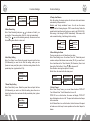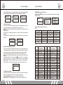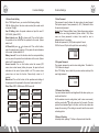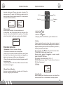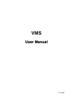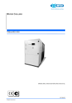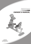
1
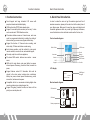
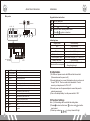
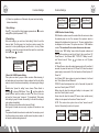
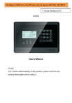
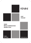
GSM&PSTN
Alarm System
Intelligent GSM&PSTN
Auto-Dial Alarm System
GSM Level
99%
Disarm
8:32PM
05/01/13 WED
Profile
For a better understanding of this product, please read this user
manual thoroughly before using it.
2013.5.V1.0
GSM&PSTN
Alarm System
CONTENTS
CONTENTS
I. Function Instruction………………………………………1
II. Alarm Panel Introduction…………………………………2
III. Initialization…………………………………………………4
IV. Function Settings…………………………………………4
1. Enter Settings………………………………………………5
2. Time Setting…………………………………………………5
3. Alarm Call & SMS Number Setting…………………………5
4. SMS Attention Number Setting……………………………6
5. Voice Recording……………………………………………7
6. Arm Delay Setting……………………………………………7
7. Alarm Delay Setting…………………………………………7
8. Timely Arm/ Disarm…………………………………………8
9. Siren Setting for Alarm……………………………………8
10. Voice Prompt………………………………………………9
11. Ring Time Setting…………………………………………9
12. Add or Delete Wireless Sensors …………………………9
13. Defense Zone Setting……………………………………9
14. Alarm Center Setting……………………………………11
15. User Password …………………………………………12
16. Program Password………………………………………12
17. Wireless Siren Setting…………………………………… 12
18. Record Checking…………………………………………12
19. Factory Reset……………………………………………13
V. Operation Instruction……………………………………13
1. System status………………………………………………14
2. Remote Controller Operation……………………………14
3. Out Arm………………………………………………………14
4. Home Arm……………………………………………………14
5. Disarm………………………………………………………15
6. Emergency Help……………………………………………15
7. Answer Alarm Call…………………………………………15
8. Remote Control……………………………………………16
VI. Technical Parameters……………………………………17
VII. Components List………………………………………17
VIII. Care and Maintenance…………………………………17
Function Instruction
I . Function Instruction
Touch keypad and large dot-matrix LCD screen with
perpetual calendar and detailed display;
GSM and land line (PSTN) dual network alarm;
Support 5 user alarm phone numbers (call or sms), 1 alarm
center number and 1 SMS attention number;
30 wireless defense zones and 4 wired zones, each zone
could be programmed individually, including the setting of
defense zone type, sensor name, bypass, alarm delay;
Support the function of 10-second voice recording, arm/
alarm delay, 100 alarm and status records saving;
Arm/ disarm operation could be realized by main panel,
remote controller, remote call, sms, and wireless keypad;
One relay output to control home appliance;
The alarm SMS content: defense zone number + sensor
name;
SMS alert for arm/ disarm, main panel battery low power,
external power off/recovery, phone line failure, sensors low
power;
Support Ademco contact ID. Information that could be
upload to the alarm center includes alarm, arm/disarm,
battery low power, external power failure/recovery, period,
manual test, and sensors low power.
Compatible with all our accessories including digital video
recorder, wireless siren, wireless keypad, etc;
Support “Ding-dong” doorbell function; and alarm call has
priority over normal phone call.
Alarm Panel Introduction
II .Alarm Panel Introduction
In order to make the main unit get the wireless signal well for all
wireless accessories, please put the alarm host at the central place of
your defense area. Make sure it's away from large metal objects and
household appliances which may cause high frequency interference,
as well as barriers such as reinforced concrete wall or fire door, etc.
Front schematic diagram:
Built-in Siren
GSM Level
99%
Disarm
8:32PM
05/01/13 WED
LCD Screen
Check
Home arm
Disarm
Set/ Return
SOS/ Delete
Out Arm
MIC
Keypad
Confirm
LCD display:
GSM Level
99%
Disarm
8:32PM
05/01/13 WED
GSM Signal
Strength
Back schematic diagram:
SIM card slot
SIM card
Battery compartment
1
2
Alarm Panel Introduction
Wire ports:
Keypad buttons instruction:
PSTN line
Phone set
14 12 10
DC12V
NO COM V+
15
Initialization
V-
Z4
Z3
13 11
NO COM V+
Z2
Z1
-
+
9 876
V-
Z4
Z3
SIM
TEL-IN
TEL-OUT
5
4
3
Z2
Z1
-
POWER
2
OFF
ON
1
+
2.2KΩ
Max.AC250V/3A
DC30V/3A
V+
out arm/ away arm
home arm
disarm: +user password+
check the alarm/ working status record.
Press
to upturn or downturn.
emergency alarm.
V- COM NC
Siren
Indicating tone:
Keypad press
Arm
Out arm or alarm with delay
Disarm
Telephone line error
External power failure
Battery low power
Remote call the main panel
3
1
ON/OFF
Power switch
2
DC 12V POWER
Power adaptor port, 12V/1.2A
3
TEL-OUT
Connect telephone set
4
TEL-IN
Connect telephone line
5
SIM
SIM card slot
6
12V output (positive. Can connect wired sensor.)
7
+
-
8
Z1
Wired sensor 1 (zone number: 31)
9
Z2
Wired sensor 2 (zone number: 32)
10
Z3
Wired sensor 3 (zone number: 33)
11
Z4
Wired sensor 4 (zone number: 34)
12
V-
Negative of siren (black cable)
13
V+
14
COM
Positive of siren (red cable)
GND
15
NO
Relay output. It will be closed for 3 minutes when alarm is
triggered.
12V output (negative. Can connect wired sensor.)
one short beep
one short beep
one short beep per second
two short beeps
two short beeps
the screen will display “AC Power Fail”
one short beep
one short beep each 3 seconds
after getting through
III.Initialization
1)Put SIM card: please insert a valid SIM card into the card slot.
(Please make sure the power is off.)
2)Connect telephone line: connect the telephone line in your house to
the port “TEL-IN”. There's a cable in the standard kit. It could
connect your telephone set to “TEL-OUT”.
3)Connect power: use the power adaptor to connect the panel to
external power supply.
4)Turn on the backup battery: turn the power switch to “ON”
IV.Function Settings
Note: 1) All the settings are found within the setting status.
2) Press
to enter/ confirm/ save,
to return and
to clear the
input content.
3) Press key numbers
to turn up/ down/ left/ right.
4
Function Settings
4) If there’s no operation over 30seconds, the panel would exit setting
status automatically.
1.Enter Settings
Press
, then input the 4-digit program password and
setting status. (default password: 1234)
to enter
2.Time Setting
After enter settings, you could see “clock setting”. Enter it to set the
time and date. The first group is for time (hour: minute: second), the
second is for date (month/day/year) and the last is for day. Please
press
to clear the previous data and then input the correct data.
And finally press
to confirm.
Operation figures:
Clock Setting
Phone No.setting
Sms Serring
Voice Recording
Clock Setting
14:35:21
05/01/2013
WED
3.Alarm Call & SMS Number Setting
This system can store 5 groups of alarm numbers. When alarming, it
will make alarm call or send sms to these numbers. And the call will be
made in order for three times automatically, until someone gets through
it.
Method: enter “phone No. setting” menu, choose “Phone Alarm” or
press
to choose “SMS Alarm”. Press
and then delete the
preset numbers. Input the number you want to set. Save it, then you
will see the “phone group” change to “2” automatically. That means
after setting a group of number successfully, it will enter the setting of
next number automatically.
Note: Each group of number could not exceed 15-digit.
Each group of number can save only as phone call number or sms
number.
The panel will handle the numbers in serial order. For example, you set
the first number as sms number, and the second as phone number, it
will send sms before making alarm call.
5
Function Settings
Phone Group 1
Phone Alarm >
SMS Alarm
Phone Group 1
Phone Alarm >
1358888888
Phone Group 2
Phone Alarm >
4.SMS Attention Number Setting
SMS attention number means the number that will receive sms when
the external power is cut off or recovered, the system is armed or
disarmed, the telephone line has error, etc. The sms content will also
be displayed on the screen. This system can store 1 SMS attention
number. This number will not receive defense zone alarm sms.
Method: enter “SMS Setting” menu, delete the preset numbers and
then input the number you want to set. Save it, then you will see “AC
Power Recover”, “Arm/ Disarm SMS”, “PSTN Off”, “Battery Low-volt”,
and “Sensor Low-volt”. Press
to choose on or off. (System
default: off)
AC Power Recover: when the external power supply is off more than 8
seconds, the panel will send sms “AC Power Fail”; when the external
power supply is recovered for 30s, it will send sms “Alarm System: AC
Power On”.
Arm/ Disarm SMS: when system is armed or disarmed, it will send
sms “Alarm System: Armed/ Disarmed”.
PSTN Off: when the telephone line is cut for 5 seconds, the panel will
send sms “Alarm System: PSTN Off”.
Battery Low-volt: when the main panel battery is in low power, it will
send sms “Alarm System: Low-volt”.
Sensor Low-volt: when the sensor (PIR sensor, door contact sensor)
battery is in low power, it will send sms “Sensor Low-volt”.
NOTE: This version alarm system does not have “sensor Low-volt”
function. Please kindly contact us if required.
SMS Phone No
13588888888
AC Power Recover
Off/On
>
Am/Dlsarm SMS
Off/On
>
6
Function Settings
PSTN OFF
Off/On
>
Battery Low-volt
Off/On
>
Sensor Low-volt
Off/On
>
5.Voice Recording
Enter “Voice Recording” and press
to choose on. Enter it; you
can start the 10-second recording. After 10s, it will exit automatically.
Press
or
can end the recording manually. Receivers can hear
this recording when there’s an alarm call.
Voice Record
Off/On
>
Voice Record
In Recording…
Time
10
6.Arm Delay Setting
Enter “Arm Delay” menu. Delete the preset time and input the time
(00~59seconds) you want to set. After this setting, when you arm
(home arm/ away arm) the system, it will enter arming status after the
preset delay time. (system default: 10s)
Function Settings
8.Timely Arm/ Disarm
After this setting, the alarm system will start arm status and disarm
automatically at the preset time.
Method: enter “timely arm/disarm” menu. You will see the screen
displays like the following diagram. “SUN” means Sunday. Delete the
preset time first and then input the time you want to set (00:00~24:59).
After saving, it will change to “MON” automatically. That means, after
each successful setting, it will change to the next day.
SUN
:
Away Arm
12:00 Home Arm
21:35 Disarm
MON
: Away Arm
: Home Arm
: Disarm
9.Siren Setting for Alarm
The siren can be set on or off when there's an alarm.
Enter “Siren Setting” menu. You will see “Zone No.”. Delete the preset
numbers and input the defense zone number (00~34) you want to set.
Save it and then set the “Siren Duration” (00~59minutes). Save it and
then set the “Built-in Siren”. Press
to choose on/off.
Siren Duration: siren ring time (default: 1minute)
Built-in Siren: the siren built-in the alarm panel
Arm Delay
10
Second
00
7.Alarm Delay Setting
Enter “Alarm Delay” menu. Delete the preset time and input the time
(00~59seconds) you want to set. After this setting, when there is an
alarm, it will make call or send sms after the preset delay time. (system
default: 10s)
Alarm Delay
10
Second
7
Zone No.
Siren Duration
01
Minute
Built-in Siren
On
>
10.Voice Prompt
Enter “Voice Prompt” menu, you can set these functions “PSTN Off”
“Arm & Disarm Siren” “Arm & Disarm Horn” as on/ off.
PSTN Off: turn on this function; the screen will display “PSTN Off”
when the telephone line is cut off. The panel will make two short beeps
at the same time.
Arm & Disarm Siren: turn on this function, the built-in siren of the panel
will make one short beep for arm operation and two short beeps for
disarm.
8
Function Settings
Arm & Disarm Horn: turn on this function; the extern siren will make
one short beep for arm operation and two short beeps for disarm.
PSTN OFF
Off
>
Arm&Disarm Siren
Off
>
Arm&Disarm Hom
Off
>
Function Settings
00 SOS help: alarm information
Alarm Delay Off/On: press 4/6 to choose to activate alarm delay
function or not
Zone No.
01
11.Ring Time Setting
When you use phone to call the alarm system and do remote control, it will get
through after several rings. This ringing times could be set (1~9).
Method: Enter “Voice Prompt” menu, then set the times of “Tel Ring Time” and
“SIM Ring Time”.
Tel Ring Time: the ringing times when you call the landline number (system
default: 6)
SIM Ring Time: the ringing times when you call the SIM card number (system
default: 3)
Tel Ring Times
6
SIM Ring Times
3
Zone Activate >
0 Defense Line >
00 SOS Help >
Alarm Delay off >
Zone Prompt >
off
Door Contact >
off
System default setting for all zones:
List 1
Zone number
00
01~10
11~20
21~29
30
31~34
Zone type
——
24-hour zone
Out arm
Home arm
Doorbell zone
——
Zone on/off
On
On
On
On
On
Off
Alarm delay
Off
Off
Off
Off
Off
Off
List 2
12.Add or Delete Wireless Sensors
This alarm system has 30 wireless defense zones, each of which supports up to
4 wireless detectors. And it supports up to 10 remote controllers. Extra sensors
and remotes have to be set with the alarm panel in order to perform normally.
Zone 00 is for remote controller and zone 01~30 are for wireless sensors.
Method: Enter “Pairing & Deleting” menu. Delete the zone No., and then input
the number (00~30) you want to set. Press
to choose “Pair”, you will see “in
paring”. At this time, you can trigger the remote controller or sensor. Please
trigger it twice. The screen will display “operation ok” after successful setting.
Choose “Delete”, you will delete all the sensors in this chosen defense zone.
Zone No.
Pair
Delete
13.Defense Zone Setting
Enter “Zone type” menu, then delete the previous zone number and input the
number (01~34) you want to set. Then you could do the settings.
Zone activate/disable: this means you want this zone work or not
Defense line: 0: 24-hour defense zone; 1: out arm zone; 2: home arm zone
9
Zone
No.
01
02
03
04
05
06
07
08
09
10
11
12
13
14
15
16
17
Alarm
Information
00 SOS Help
00 SOS Help
01 Panic Button
02 Panic Button
03 Fire Alarm
03 Fire Alarm
05 Kitchen Alarm
15 Glass Alarm
15 Glass Alarm
07 Tamper Alarm
10 Door Alarm
10 Door Alarm
11 Front Door
12 Back Door
13 Side Door
14 Window Alarm
14 Window Alarm
CID Zone
code No.
E100
E100
E121
E120
E110
E110
E130
E131
E131
E137
E134
E134
E134
E134
E134
E131
E131
18
19
20
21
22
23
24
25
26
27
28
29
30
31
32
33
34
Alarm
Information
15 Glass Alarm
18 Garage Alarm
09 Out Arm
19 PIR Alarm
19 PIR Alarm
19 PIR Alarm
20 Living room
20 Living room
21 Bedroom Alarm
21 Bedroom Alarm
21 Bedroom Alarm
18 Garage Alarm
24 Doorbell
10 Door Alarm
09 Out Arm
09 Out Arm
19 Out Arm
CID
code
E131
E130
E131
E132
E132
E132
E130
E130
E130
E130
E130
E130
E134
E131
E131
E132
10
Function Settings
14.Alarm Center Setting
Enter “CMS Upload” menu, you can do all the following settings:
CMS No. Setting: this is the alarm center number (this number could
not exceed 15-digit).
User ID Setting: delete the preset numbers and input the new ID
(0001~9999). (default: 0001)
Status Upload: press
to choose on/off. Turn on this function;
the operation of arm/ disarm will be uploaded to the center. System
default is off.
AC Power Fail: press
to choose on/off. Turn on this function;
when the external power supply is off, the panel will send information
to the center. System default is off.
Battery Low-volt: Turn on this function; when the main panel battery
is in low power, the panel will send information to the center. System
default is off. System default is off.
Sensor Low-volt: Turn on this function; when the sensors (PIR
sensor, door contact sensor) battery low power, the panel will send
information to the center. System default is off. This version alarm
system does not have this function. Please kindly contact us if
required.
Manual test: Turn on this function; all the operations and settings of
the main panel will be uploaded to the center. System default is off.
Period Time: 00001~99999minutes 00000 means off.
11
CMS No.Setting
075588888888
User ID Setting
001
Status Upload
Off
>
AC Power Fail
Off
>
Battery Low-volt
Off
>
Sensor Low-volt
Off
>
Manual Test
Off
Period Test
00000
>
Function Settings
15.User Password
This password is used to disarm the alarm system by panel keypad.
This system supports 3 user passwords (A, B, C). Password A is also
the remote call password.
Method: Enter “Password Setting” menu. Delete the previous numbers
and input the new 4-digit password. (System default: 1234) When
users use these passwords to disarm, there would be sms to
distinguish them. For example:
Disarm with password A: (XXXX) alarm system A: Armed
XXXX is the user ID (refer to the part “alarm center setting”)
Password Setting
****
****
****
16.Program Password
The program password is used to enter setting status. The default is
1234. Users can change it.
Enter “PIN Setting” menu; delete the previous numbers and input the
new 4-digit password.
PIN Setting
****
17.Wireless Siren Setting
If you want wireless sirens to work together with this alarm system, you
need to set them first.
Set the wireless siren into coding status (refer to siren user manual),
and then press button
on the main panel for 2 seconds. The main
panel will send wireless signal to the siren, and the siren makes two
beeps after receiving it. The setting is successful and the siren could
exit coding status.
18.Record Checking
In standby status, pressing “0” button on the panel could check the
12
Operation Instructions
alarm and working record. Press
to upturn or downturn. This
system can store 100 records. The last status is ranked as the first
record. And when the record number exceeds 100, the most previous
record will be deleted automatically.
Operation Instructions
Out Arm
Disarm
Home Arm
03:Working Log
Armed
01/01 09:37 AM
19.Factory Reset
When the system is unstable, it is recommended to reset it.
In setting status, enter “Factory Reset” menu, and then press 4/6 to
choose on. And save this setting. After this operation, all the settings
return to factory default, and the alarm records would be all deleted.
Factory Rest
On
>
V.Operation Instructions
1.System status. There are 4 statuses as following:
☆Arm/ away arm: all detectors will be in working status
☆Home Arm: in arm status, the defense zone which is set as [Home
Arm Zone] will not make alarm when detectors are triggered; only
detectors in out arm zone and 24-hour zone will trigger alarm
☆Disarm: the system will not alarm when detector triggered (except 24
hours defense zone)
☆System setting status: In this status, all defense zones will not alarm
when detectors are triggered.
2.Remote Controller Operation
Users can use remote controller to set system as Out/ Away Arm,
Home Arm, Emergency Alarm, and Disarm.
13
Emergency
Alarm
07:Alarm Log
00 Defense Zone
SOS Help
01/05 04:42 PM
☆Out Arm: Press button
☆Disarm: Press
button
☆Home Arm: Press button
☆Emergency Alarm: Press SOS button, system will alarm at once.
3.Out Arm
It means to guard all around your house while everyone is going out;
all the detectors of the host are always working; when the detector is
triggered by detecting source (anti-theft, fire prevention, gas leak, etc.),
the alarm system will sound the alarm.
Main unit operation: Press
button, the system will enter arm status
10seconds later or after the delay time set by user
Remote controller operation: Press button on remote controller,
system will enter OUT ARM status
SMS operation: user password (Default: 1234) + [1]
After the setting, the panel makes "Di" sound, and you will receive a
SMS: Alarm System armed.
LCD display:
Away Arm
4:43PM
01/16/13 WED
4.Home/Stay Arm
Home arm means part of the defense zones are in arm status. When
there's someone at home, it is recommended, for safety purpose, to
14
Operation Instructions
enable some of the detectors (such as sensors for door, window,
balcony, etc), and disable the others (such as sensors for the hall or
some places easy to be triggered by person at home).
Main unit Operation: Press
button on keypad
Remote Control Operation: Press
button on remote controller once
LCD display:
Home Arm
4:45PM
01/16/13 WED
5.Disarm
The purpose of disarming the system is to let it not in alert status. One
way is normal disarming after operation of arming, and the other is to
stop the main unit alarming. After the operation of disarm, all the
defense zones except 24-hour zone shall not work.
Main unit Operation:
+ user password +
Remote Control Operation: Press
button on remote controller
SMS operation: user password (Default: 1234) + [0]
After the setting, the panel makes "Di" "Di" sound, and you will receive
a SMS: Alarm System disarmed.
LCD display:
Disarm
4:46PM
01/16/13 WED
6.Emergency Help
Sometimes, there may be some accidents happening (a senior person
or child suddenly becoming ill or being in great pain, a fire emergency,
burglar intrusion). Press [SOS] button on keypad, or SOS button on
remote controller or wireless panic button, the main unit will alarm and
make calls to the preset user numbers.
Operation Instructions
and user phone numbers. If no one answers the call, the system will
call the next user number automatically. The system will call each
preset numbers for 3 times in order.
If you hang-up directly without answering the call, the system will call
each preset number for 3 times circularly.
If you answer the call, you will hear the pre-record voice. You can set
system via your telephone or mobile phone keypad.
Press [1]: Main unit stops alarming and Arm; the call is hung up
directly and it stops calling users.
Press [2]: Main unit stops alarming and Disarm; the call is hung up
directly and it stops calling users.
Press [3]: Turns the siren off and monitors the scene for 30 seconds.
Within the 30s, you can press 1/2/4/*. And if there's no operation for
30s, it will hang up automatically.
Press [4]: Replays the pre-recorded voice. After this operation, you
can still press 1/2/3/*.
Press [*]: Hang up the call and stops alarming.
Note: the alarm SMS number will receive alarm message: Alarm
System + zone number + alarm type.
8.Remote Control
Dial the number associated to the alarm panel by phone (mobile
phone), and after one ringing cycle, you can hear a “Di” sound. Then
press “user password A+#”. A “Di” sound indicates operation correct,
and now you can:
Press [1]: out arm; the call is hung up directly
Press [2]: disarm; the call is hung up directly
Press [3]: monitoring for 30 seconds. Within the 30s, you can press
1/2/4/*. And if there's no operation for 30s, it will hang up automatically.
Press [4]: Replays the pre-recorded voice. After this operation, you
can still press 1/2/3/*.
Press [*]: Hang up the call.
7.Answer Alarm Call
When the main unit sounds alarm, it will dial the preset alarm center
15
16
Technical Parameters
VI.Technical Parameters
Main panel
Input voltage: DC12V/ 1.2A
Standby current: <50mA
Alarming current: <500mA
GSM band: 850/900/1800/1900MHz
Wireless frequency: 315/433/868MHz (default: 433)
Backup battery: 3.7V/ 1200mA LI rechargeable battery
Standby time: 10~12hrs
Recharging time: 12hrs
Working Temperature: 10℃~+40℃
Humidity: ≤90% ( no fog)
Wireless detectors: 120pcs
VII.Components List
Main panel
Remote controller
Siren
Wireless PIR sensor
Wireless door sensor
Telephone line
Power adapter (DC 12V/1.2A)
User manual
1 pc,
2 pcs,
1 pc,
1 pc,
1 pc,
1 pc,
1 pc,
1 pc.
VIII.Care and Maintenance
The alarm system has excellent design and uses advanced
technologies. It shall be used with care. The following suggestions are
required to maintain your obligations under the warranty terms, and for
prolonging the service life of the system.
Place the control panel and all parts and accessories out of
children's reach.
Keep the alarm system dry. Rain, humidity and various fluids or
moisture all will corrupt the electronic circuit.
Do not use or place the alarm system in dirty locations, otherwise
the electronic elements will be damaged.
17
Care and Maintenance
Do no place the system in excessively hot locations. High
temperature will shorten the service life of electronic equipment,
damage batteries, deform or even melt some plastic parts.
Do not place the system in excessively cold locations. Otherwise
condensation many occur and damage the circuit board of the alarm
system.
It is recommended that you check and test the alarm system
periodically:
Check the main unit every three months:
1.Whether it can arm/disarm normally;
2.Whether it can dial the number for alarm normally;
3.Whether it can receive wireless detectors' signal normally;
4.Whether the back-up battery can work normally.
Check the wireless detectors once a month:
1.Trigger wireless detectors to see if system can alarm normally;
2.Check all detectors' batteries to see if it's in low voltage;
3.Check whether wireless detectors can send signal to the main unit
normally.
Check the SIM card:
1.Check the use of SIM card, such as network signal, balance, etc.
2.Make sure the PIN code verification of the SIM card is closed.
3.Please keep the password and SIM card number safe, in case that
other people remote control the system illegally.
Since the alarm system is continuously in operation or standby mode,
the supply adaptor of the control panel shall be connected to a safe
and reliable socket.
Do not place the system near your bedroom or office table, because
the siren will make high-loudness sound in the case of alarm, which
may adversely affect your rest or work.
If the alarm system will not be used for a long time, please
disconnect the system from the power supply.
Please do not disassemble, repair or alter the products without
permission, or it may cause accidents and faults.
Do not drop this product on the ground or on hard objects, as it may
lead to massive impact to cause faults and damages.
18
Care and Maintenance
Care and Maintenance
Without approval and consent of relevant authorities, please do not
set “112”, “911” or the alarm phone number of police station for this
main unit.
Please read the suggestions above carefully and follow the instructions
herein. If any of the equipment does not work properly, please send it
to the dealer or authorized service point for repair. We will try our best
to solve the problem for you as soon as possible.
The following accessories are optional:
Signal booster
Door sensor
Remote controls
PIR detector
Optional sensors/detectors are packed separately. You can choose
according to your specific requirements.
18
19