Transcript
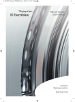
501 Manual
501 Manual
501 Manual
Terminal Connections
Specifications
C NO NC
COMMON
12 13 14
STOP
9 10
START
8
SUPPLY
1
3
COMMON
Terminal 13 must always be connected to the high-level electrode.
This also applies if you change from pumping out (default) to
pumping in. Only here it will function as the STOP electrode.
Settings for pumping out / pumping in
The 501 Electrode Control is set up from the factory to pumping
out (emptying). This setting can be changed to pumping in (filling)
by moving a jumper inside the cabinet as shown below:
115 VAC / 230 VAC
Function
The transmitter generates an alternating voltage applied to the
electrodes. When the liquid connects the electrodes, the current
running between these is amplified and the output relay is activated.
Two electrodes can be connected to the unit for the detection of
one level, or three electrodes can be connected for the detection of
two levels; one for start and one for stop. In cases where the liquid
is in a conductive tank, or where for example a metal pipe is in
constant contact with the liquid, the tank or piping can be
substituted for one of the electrodes by simply attaching a wire to it
and the connection housing, usually as a common contact. (see
diagram top middle).
501 Manual US 081104
Enclosure
Mounting
12 VDC
Relay
Emtying
Filling
Relay
Materials
Dimensions
Filling
Fuse
Special Features
• Price competitive and reliable system for level control in
conductive liquids
• The amplifier is easily mounted on a DIN-rail
• The electrodes can be suspended by a cable or threaded directly
to a Lexan and Noryl plastic electrode base housing with a 1”
thread (see diagram at far right)
• The electrode base housing can be mounted on a special acidproof MJK 316 SS sensor brackets (200219 and 200220) which
can be wall mounted, pipe or rail mounted (using Universal
Brackets 200205) or mounted on a wall with an extension arm
(200210 plus 200215)
Electrodes
Description
Length
Fuse
General
The 501 Electrode Control is a simple and price competitive system
for level control in conductive liquids. The system includes a
transmitter for DIN-rail mounting and various level electrodes.
Emtying
This installation manual applies to:
-209820 501 Electrode Control 115 VAC
-202820 501 Electrode Control 230 VAC
-202830 501 Electrode Control 12 VDC
Part numbers
Dimensions
Mounting
Power supply
Consumption (relay off)
Comsumption (relay on)
Temperature range
Materials
Cover
Base
CE approvals
Enclosure
Relay output
Emptying
Filling
Emptying
Filling
Supply
Supply
1
3
1
3
P
0
+
-
Part numbers
209820
501 Electrode Control / 115 VAC
202820
501 Electrode Control / 230 VAC
202830
501 Electrode Control / 12 VDC
202850
Level electrode (19 ft cable; normally not used
with electrode base)
202860
Electrode base with level electrode (1m rod)
202864
Electrode base with 4 level electrodes (1m rods)
202865
Level electrode for use with p/n 202860 (1m rod)
209820 (202820)
202830
86 x 52,5 x 58 mm (h x w x d)
On DIN-rail
11-16 VDC
115 (230) VAC±10%
<1mA
Approx. 4VA
40mA
-4°F to +140°F (-20°C to + 60°C)
Lexan (grey)
Noryl (black)
EN50081-1, EN50082-1
IP22
Voltage-free switch
(max. 250V, 4A resistive,1A inductive)
202850
202860 (64)
202865
Single
Electrode base
Additional
electrode
incl. one (four)
rod for p/n
electrode rod(s)
202860
IP68
IP65
IP68
Suspended in
Mounted with M5 Mounted in
19.6 ft cable
thread
base with
incl. 5.9”
M5 thread
electrode
5.9” / 150mm
39.4” / 1000mm
38.4” /
975mm
AISI 316
POM / AISI 316
AISI 316