1
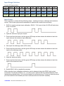
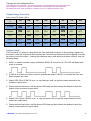
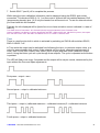
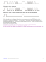
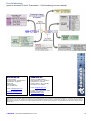
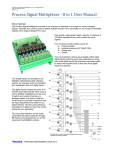
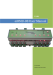
Filename: Current Transmitter - DC Powered User Manual.docx Date: 31 May 2012 Version: 1.01 Current Transmitter - DC Powered User Manual Description: This current transmitter has been designed using a dedicated, precision, true RMS to DC converter in combination with the most recent, low-cost, powerful microprocessor. This enables us to offer flexibility, reliability and accuracy at a good price in a small package. Using miniature DIP switches a variety of standard inputs and outputs can be selected and with the ‘one button’ calibration accurate operation in any configuration is assured. After the required input and output ranges are selected, these can be adjusted to be anything within the range using the ‘one button’ calibration. Output inversion is also easily accommodated. The Zero and Span trimpots can be disabled or switched to a wider adjustment range using the DIP switches. Filtering is also DIP switch selectable in four ranges up to 60 seconds. Included in the design is a full wave rectifier and zero crossing detector. These provide for current measurement on a ‘per cycle basis’ for high speed applications and also accurate frequency measurement. Firmware changes can be done if you have a special application that we have not catered for. How it Works: A description of how it works will be included here. [functional diagram to be inserted here] Figure 1. DIP Switches for Range Selection and Options. Accessible beneath side cover decal. © danntech – PROCESS INSTRUMENTATION 2012 1 Input Range Selection: Set with DIP Switch (SW1): DIP Switch # Shunt 1/A 2/B 3/C 4/D 5/E 6/F 7/G 8/H 0-1 A 0R075 open closed open closed open open open closed 0-5 A 0R025 closed closed open closed open open open closed Input Input Setup: This is cleverly () done with the following steps – injecting minimum, midrange and maximum values. This to allow polynomial linearization to improve the overall device accuracy: 1. SW2-5 is used to activate input calibration. SW2-6, 7 & 8 must all be off. LED will flash twice every 2 seconds. 2. Inject the minimum input you require. 3. Press and hold the button until the green LED stays on then release the button to latch the input value as the minimum input calibration. 4. Now inject the midrange value (50% value). 5. Press and hold the button until the green LED stays on then release the button to latch the input as the midrange value. 6. Inject the maximum value. 7. Press and hold the button until the green LED stays on then release the button to latch the input as the maximum value. 8. Switch SW2-5 off to complete the process. While doing the input calibration information can be observed using the RS232 jack socket connection. This works at 9600, 8, N, 1 no flow control. Without the link installed between CN2 (programming header) pins 1 & 2 only the header line will be sent out. To see the internal values you must have this link installed (the unit is delivered with this link NOT installed). © danntech – PROCESS INSTRUMENTATION 2012 2 Typically the info displayed will be: True RMS Current Transmitter - DC Powered (dt374) Copyright Danntech 2012 Firmware V200 Input Cal Mode. Use Button to capture Input Minimum, Input Midpoint and Input Maximum Ain=2955 VR1=3727 VR2= 857 SW1= 24 Button=0 m=1.06 c=580.20 DACOut=3737 Output Range Selection: Setup using DIP Switch (SW1): DIP Switch # Output 1/A 2/B 3/C 4/D 5/E 6/F 7/G 8/H 4-20mA ON OFF OFF OFF OFF ON OFF OFF 0-20mA ON OFF OFF OFF OFF ON OFF OFF 0-5V OFF ON OFF OFF OFF ON OFF OFF 0-10V OFF ON OFF OFF OFF ON OFF OFF ±10V OFF ON ON OFF ON OFF ON OFF Output Setup: This is cleverly () done by using either the Zero and Span trimpots, or by injecting a signal into the input to vary the output and then latching the minimum and maximum values desired. Can also be used to invert the output – making the maximum say =4mA and the minimum =20mA. Use the following steps: 1. SW2-7 is used to activate output calibration. SW2-5 & 8 must be off. The LED will flash twice every 2 seconds. 2. If SW2-6 is off then the input is used to activate the output. If SW2-6 is on then the Zero and Span trimpots are used. 3. Adjust VR2 (Zero) if SW2-6 is on, or vary the input until you get the output desired for the minimum output value. 4. Press and hold the button until the green LED stays on then release the button to latch the output as the minimum output value. 5. Adjust VR1 (Span) if SW2-6 is on, or vary the input until you get the output desired for the maximum output value. 6. Press and hold the button until the green LED stays on then release the button to latch the output as the maximum output value. © danntech – PROCESS INSTRUMENTATION 2012 3 7. Switch SW2-7 (and 6) off to complete the process. While doing the input calibration information can be observed using the RS232 jack socket connection. This works at 9600, 8, N, 1 no flow control. Without the link installed between CN2 (programming header) pins 1 & 2 only the header line will be sent out. To see the internal values you must have this link installed. Typically the info displayed will be [would be nice to have activation source indicated i.e. state of SW2-6]: True RMS Current Transmitter - DC Powered (dt374) Copyright Danntech 2012 Firmware V200 Output Cal Mode. Use Button to capture Output Min and Max. <SW2-6 OFF=Ain, ON=POTs top=zero, bot=span> Ain= 535 VR1=3727 VR2= 857 SW1=104 Button=0 m=1.07 c=285.11 DACOut= 857 Test: There is a test function built in which is activated by switching on SW2-8 with switches SW2-5, SW2-6 & SW2-7 off. In Test mode the output can be switched from following the input, to minimum output value, to a value for approximately 4mA output (if the output is set for current, otherwise approximately 2 volts), then 12 mA (50% output), then 20mA (100% output) and then 22mA (maximum output value). Using the button you can cycle through these outputs. The cycle is repeated as the button is pressed. The LED will flash once every 2 seconds and the output will be as per normal, determined by the input without the Zero and Span adjustments First press – output = zero Second press – output = calibrated minimum Third press – output = (calibrated maximum – calibrated minimum)/2 + calibrated minimum Fourth press – output = calibrated maximum © danntech – PROCESS INSTRUMENTATION 2012 4 Fifth press – output = maximum Sixth press – output = normal and follows input without Zero and Span adjustments While doing the input calibration information can be observed using the RS232 jack socket connection. This works at 9600, 8, N, 1 no flow control. Without the link installed between CN2 (programming header) pins 1 & 2 only the header line will be sent out. To see the internal values you must have this link installed. Typically the info displayed will be: True RMS Current Transmitter - DC Powered (dt374) Firmware V2.00 Copyright Danntech 2012 Use Button to Cycle through outputs => 0, min, (max-min)/2, max 4095 Ain= 536 VR1=3727 VR2= 858 SW1=136 Button=0 m=1.07 c=285.11 DACOut= 859 Tm=1.00 Tc=0.00 Runtime= 122 © danntech – PROCESS INSTRUMENTATION 2012 5 DIP SW2 Operational Settings: SW2 1/A Description Default Setting Zero and Span Trimpot Enable Enables the operation of the Zero and Span trimpots on the front panel. You can enable the trimpots, make your adjustments and then when you disable the trimpots, the values that you last adjusted are saved and used until the trimpots are enabled again. ON OFF = trimpots disabled ON = trimpots enabled Zero and Span Normal/Wide Range Adjustment Select Provides “normal” and “wide” trimpot adjustments for Zero and Span. 2/B OFF = Zero and Span adjustment are normal i.e. approx +/-10% over full trimpot range. OFF ON = Zero and Span adjustment are “wide” i.e. approx +/-50% over trimpot range. 3/C 4/D Note that you may need to adjust zero and span several times to get the best accuracy. Filtering Select Selects the moving average filter step response time: Filter Step Response SW2-3/C SW2-4/C Time (seconds) No filtering – step response OFF OFF approximately 0.2 sec OFF ON 1 sec ON OFF 10 sec ON ON 60 sec OFF ON Input Calibration Calibrates the input circuit to take into account any component tolerances for the input range selected. Using calibrate button to indicate the required input is present at the input. You must follow the sequence and carry out all three steps in order. Uses three values to fit polynomial to input calibration for highest accuracy operation. 5/E Inject Minimum Input Value – press and hold button until green LED stops flashing and stays on, then release button. OFF Inject Midrange Input Value – press and hold button until green LED stops flashing and stays on, then release button. Inject Maximum Input Value – press and hold button until green LED stops flashing and stays on, then release button. © danntech – PROCESS INSTRUMENTATION 2012 6 Output Calibration Activation Source Select 6/F OFF = Input is selected as the output activation source. OFF ON = Zero and Span trimpots selected as the output activation source for minimum and maximum output values. Output Calibration Calibrates the output circuit to take into account any component tolerances for the input range selected and the output range required. 7/G Uses the calibrate button to indicate the required output is present at the output. You must follow the sequence and carry out both steps in order. The output can be set using the input (SW2-6/F = OFF) or the values are set using the Zero and Span trimpots (SW2-6/F = ON). OFF Select output activation source Ain or trimpots. Set input or Zero trimpot for the minimum output required - press and hold button until green LED stops flashing and stays on, then release button. Set input or Span trimpot for the maximum output required - press and hold button until green LED stops flashing and stays on, then release button. Test Built-in test function which is activated by switching on SW2-8/H with switches SW2-5/E, SW2-6/F & SW2-7/G off. 8/H In Test mode the output can be switched in sequence from 1. following the input, to 2. minimum possible output value, to 3. a value for approximately 4mA output (if the output is set for current, otherwise approximately 2 volts), 4. then 12 mA (50% output), 5. then 20mA (100% output) and 6. then 22mA (maximum output value) 7. then back to following the input – step 1. OFF Using the calibrate button you can cycle through these outputs. The cycle is repeated as the button is pressed. Power Up: On power up the following is sent to the RS232 port irrespective of the CN2 link. True RMS Current Transmitter - DC Powered (dt374) Copyright Danntech 2012 Firmware V200 Normal power up! If the device has restarted due to a watchdog reset then instead of Normal power up! The following will be displayed instead: True RMS Current Transmitter - DC Powered (dt374) Copyright Danntech 2012 Firmware V200 Restarted processor because of watchdog timeout! © danntech – PROCESS INSTRUMENTATION 2012 7 Specifications: 1. Standard inputs: 0-1A, 0-5A (others possible). Can also be used with clamp on current transformer for AC current measurements 0 up to 75 A. 2. Standard outputs (DIP switch selectable): 4-20 mA, 0-20 mA, 0-5 V, 0-10 V, ±10 V. 3. True RMS conversion from DC up to 10 kHz. 4. Isolation 1000 V AC RMS – three way isolation between input, output and auxiliary power supply. 5. Response time approximately 200 mS (with filter off). 6. Optional filtering, selection with DIP switches – 0.1, 1, 10 and 60 seconds step responses to eliminate noise if required. 7. High speed option available – per cycle response. 8. Internal trimpot adjustment of output minimum and maximum which can be locked using DIP switch. 9. Power-On LED indication. 10. Microprocessor based – latest architecture. 11. Smart input and output calibration (re-ranging) using push button switch and LED. 12. Linearity better than 0.2% of full scale. 13. Auxiliary supplies 12 VDC and 24 VDC ±10%. Auxiliary supply current: 12 VDC at 80mA + Iout, 24 VDC at 45mA + Iout. 14. Operating temperature -10°C to 70°C. 15. DIN rail mounting with flame proof high quality enclosure. 16. Screw terminal connections for wire diameter 2.5 mm2. 17. Dimensions 25 x 80 x 85 mm (W x H x D). © danntech – PROCESS INSTRUMENTATION 2012 8 Part Numbering: (see the document Current Transmitters – Part Numbering for more details) danntech Ltd danntech cc Co. No. 6510211 15 College Close, Hamble-le-Rice Southampton, Hampshire SO31 4QU United Kingdom Tel: 075 9069 1824 Reg. No. CK1986/15338/23 Tel International: +27 11 7921239 Tel National: 011 7921239 Fax International: +27 11 7924687 Fax National: 011 7924687 e-mail: [email protected] e-mail: [email protected] www.uk.danntech.info P O Box 1023, Fontainebleau, 2032 Republic of South Africa www.danntech.com Danntech makes no warranty of any kind with regard to this material, including, but not limited to, the implied warranties of merchantability and fitness for a particular purpose. Danntech shall not be liable for errors contained herein or for incidental or consequential damages in connection with the furnishing, performance or use of this material. This document contains proprietary information, which is protected by copyright. No part of this document may be photocopied, reproduced, or translated into another language without the prior written consent of Danntech. The information in this document is subject to change without notice. © danntech – PROCESS INSTRUMENTATION 2012 9