1
For the Owner and the Installing Contractor
ASAHI
User's Guide
Serial No. :UA-001E
Read and use the information contained within these documents.
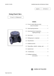
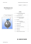
This User's Guide contains information important to the proper installation,
maintenance and safe use of the BALL VALVE TYPE21, 21α store in an
easily accessable location.
Warning & Caution Signs
㪮㪸㫉㫅㫀㫅㪾
㪚㪸㫌㫋㫀㫆㫅
This symbol reminds the user to take caution due to the potential for serious injury or death.
This symbol reminds the user to take caution due to the potential for damage to the valve if used in such a manner.
Prohibited & Mandatory Action Signs
Prohibited: When operating the valve, this symbol indicates an action that should not be taken.
Mandatory action: When operating the valve, this symbol indicates mandatory actions that must be adhered to.
General Information for Transportation, Unpacking and Storage
㪚㪸㫌㫋㫀㫆㫅
This valve is not designed to handle impacts of any kind. Avoid throwing or dropping the valve.
-Avoid scratching the valve with any sharp object.
-Do not over-stack cardboard shipping boxes. Excessively stacked packages may collapse.
-Avoid contact with any coal tar creosote, insecticides, vermicides or paint.
(These chemicals may cause damage to the valve.)
-Store products in their corrugated cardboard boxes. Avoid exposing products to direct sunlight, and store them
indoors (at room temperature). Also avoid storing products in areas with excessive temperatures. (Corrugated
cardboard packages become weaker as they become wet with water or other liquid. Take care in storage and
handling.)
-After unpacking the products, check that they are defect-free and meet the specifications.
Inspection Items
㪚㪸㫌㫋㫀㫆㫅
Check for flaw, crack, or deformation on the valve.
Check for the smoothness of handle operation.
Check for leaks to the outside or inside.
Inspect the cap nut and be sure it is not loose.
General Operating Instructions
㪮㪸㫉㫅㫀㫅㪾
㪚㪸㫌㫋㫀㫆㫅
-Certain liquid such as H2O2, NaClO, etc may be prone to vaporization (Off-Gassing) which may cause irregular
pressure increases, which may destroy the valve.
-Do not change or replace valve parts under line pressure.
-Using a positive-pressure gas with our plastic piping may pose a dangerous condition due to the repellent force
particular to compressible fluids even when the gas is under similar pressures used for liquids. Therefore, be sure
to take the necessary safety precautions such as covering the piping with protective material. For inquiries, please
contact us. For conducting a leak test on newly installed piping, be sure to check for leaks under water pressure. If
absolutely necessary to use a gas in testing, please consult your nearest service station beforehand.
-Do not step on or apply excessive weight on valve. (It can be damaged.)
-Do not use the valve to fluid containing slurry. (The valve will not operate properly.)
-Do not use the valve in conditions where the fluid may have crystallized. (The valve will not operate properly.)
-Keep the valve away from excessive heat or fire. (It can be damaged, or destroyed.)
-Before opening or closing a lubricant free product, be sure to apply water.
-Always operate the valve within the pressure vs. temperature range.
(The valve can be damaged or deformed by operating beyond the allowable range.)
-Allow sufficient space for maintenance and inspection.
-Select a valve material that is compatible with the media. For chemical resistance information, refer to “CHEMICAL
RESISTANCE ON ASAHI AV VALVE”. (Some chemicals may damage incompatible valve materials.)
-Keep the valve out of direct sunlight, water and dust. Use cover to shield the valve.
(The valve will not operate properly.)
-Perform periodic maintenance.
(Leakage may develop due to temperature changes or periods of prolonged storage, rest, or operation.)
1
ASAHI AV VALVES
For the Owner and the Installing Contractor
ASAHI
User's Guide
Serial No. :UA-001E
General Operating Instructions
㪮㪸㫉㫅㫀㫅㪾
㪚㪸㫌㫋㫀㫆㫅
-Be sure to conduct a safety check on all hand and power tools to be used before beginning work.
-Wear protective gloves and safety goggles as fluid remain in the valve even if the pipeline is empty. (You may be injured.)
-When installing a pipe support by means of a U-band or something similar, take care not to over-tighten.
(Excessive force may damage the pipe.)
-Take care not to over-tighten the Union Nut. (The valve can be damaged.)
-The installed valve must never be opened or closed when foreign matter such as sand is present in the pipeline.
- Do not use the pipe wrench. (The valve can be damaged.)
-When installing pipes and valves, ensure that they are not subjected to tension, compression, bending, impact, or
other excessive stress.
-When installing, disassembling, or reassembling the piping, fix the End Connector.
-Fasten the Union Nut while avoiding the parallelism and axial misalignment of the flange surface.
-When connecting an ASAHI AV Valve to metal piping, take care not to let pipe stress to ASAHI AV Valve.
-When installing a piece of equipment at the end of the piping line, be sure to keep the secondary (Downstream) End
Connector and Union Nut installed on the valve.
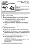
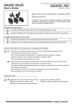
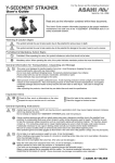
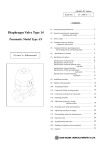
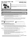
-When installing Ball Valve Type 21 and 21α, 15 to 50 mm (1/2" to 2") in end
BODY
UNION NUT
of line service, note the direction of flow.
(Find the mark ◀ molded on the Carrier-side body. On the secondary
END CONNECTOR
(Downstream) side, the Carrier is integral with the valve body. This is the
preferred method of installation when installing the equipment at the end of
the line for safety purposes.)
-Before a water test, be sure that the Union Nut is tightly fastened.
-Ball Valve Type21: When loosening the cap nut on the union side, install the
body cap (hold it with your hand) and perform installation accordingly. (If the
DESIGNATION (Carrier side)
body cap turns, the union will turn together, resulting in the union and ball
separating from the body.) If the union is loosened, retighten the union.
Installation Procedure
The connection method of the BALL VALVE TYPE21 and 21α, there are Flanged End, Socket End, Threaded End and Spigot End.
Install according to the preferred method of joining for the particular application. As for details, refer to the User's manual separately.
Flanged End
㪚㪸㫌㫋㫀㫆㫅
-The parallelism and axial misalignment of the flange surface should
be under the values shown in the following table to prevent damage to
the valve.(A failure to observe them can cause destruction due to stress
application to the pipe)
-Use flat faced flanges for connection to AV Valves.
-Ensure that the mating flanges are of the same standards.
-Be sure to use sealing gaskets (AV Gasket), bolts, nuts, and washers
and tighten them to specified torques.
1. Cleaning: Confirm the flange face area is clean and free of dirt or
foreign materials.
2. Set the AV gasket between the flanges. Insert washers and bolts
from the pipe side, insert washers and nuts from the valve side, then
temporarily tighten them by hand. Tighten the bolts and nuts gradually
with a torque wrench to the specified torque level in a diagonal manner.
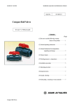
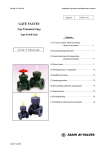
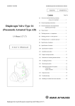
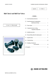
< Axial Misalignment and Parallelism of Flanged face >
Nom. Size
15 - 32 (1/2"-1 1/4")
40 - 80 (1 1/2"-3")
100 (4")
PTFE, PVDF coated
Rubber
17.5 {179} [155]
8.0 {82} [71]
Socket End
Unit: mm (inch)
Parallelism (a-b)
0.5 (0.02")
0.8 (0.03")
1.0 (0.04")
Axial Misalignment
1.0 (0.04")
1.0 (0.04")
1.0 (0.04")
< Recommended Torque Value >
Nom. Size
15, 20 (1/2"-3/4")
(Axial Misalignment) (Parallelism)
a
25-40 (1"-1 1/2")
20.0 {204} [177]
20.0 {204} [177]
b
(Fig. 1)
Unit: N・m {kgf・cm} [lb・inch]
50, 65 (2", 2 1/2")
80, 100 (3", 4")
22.5 {230} [200]
22.5 {230} [200]
Threaded End
30.0 {306} [266]
30.0 {306} [266]
Spigot End
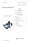
1. Loosen the union nut and remove the union nut and the end connector.
2. Lead the union nut through the pipe.
3. The end connector is joined according to each joining method.
1.
Body
2.
3.
Pipe
Union Nut
End Connector
Union Nut
Union Nut
2
ASAHI AV VALVES
For the Owner and the Installing Contractor
ASAHI
User's Guide
Socket End
㪮㪸㫉㫅㫀㫅㪾
Serial No. :UA-001E
(End connector material: PVC, C-PVC)
-When using an adhesive, ventilate the space sufficiently, prohibit the use of fire in the vicinity, and do not inhale
adhesive vapors directly.
-If an adhesive gets into contact with your skin, wash it off immediately. If you feel sick or find any anomaly, receive a
physician's diagnosis and take appropriate measures promptly.
㪚㪸㫌㫋㫀㫆㫅
-Take care in doing work at low temperatures. Solvent vapors are hard to evaporate and are likely to remain.
(Solvent cracks may occur, damaging the equipment.) After assembling the piping system, open both ends of the piping
and use a fan (of the Low-Voltage Type) or something similar to ventilate the space, thus removing the solvent vapors.
-Do not apply more cement than necessary. Avoid getting cement in the internals of the valve. This can cause damage
to the seals and moving parts. Solvent and fumes can chemically attack the valve materials if allowed to enter the
internals of the valve. (Cementing with the valve in a vertical position should be avoided)
-Do not under any circumstances try to insert a pipe into another fitting or valve by striking it, which may break the
piping.
-Use Asahi AV cement Number-32, Number-52, or Number-62 for PVC and Number-88 for C-PVC in case of JIS Pipe &
Fittings. The other standard Pipe & Fittings shall be used industrial proper PVC or C-PVC cement.
-Allow 24 hours for solvent cement to dry before performing a water leak test.
4. Entry of the Bench Mark: The bench mark indicates the maximum
penetration depth of the pipe into the end connector.
5. Cleaning: Clean the hub part of the end connector by wiping with a waste
cloth.
6. Application of adhesive: Apply adhesive evenly to the hub part of the end
connector and the pipe spigot.
7. Insertion: After applying adhesive, insert the pipe quickly into the end
connector and leave it alone for at least 60 seconds.
8. Insertion completion: Wipe away overflowing adhesive.
Threaded End
㪚㪸㫌㫋㫀㫆㫅
Cement
(End connector material: PVC, C-PVC, PP, PVDF)
-Make sure that the threaded connections are plastic x plastic.
(Metallic thread can cause damage.)
-Wrap the threaded joints on our plastic piping with sealing tape.
Using a liquid sealing agent or liquid gasket may cause stress cracks
(Environmental Stress Cracking). Our product warranty shall not
apply in case of said use, even when said use is unavoidable.
-Avoid excessive tightening. (The valve can be damaged.)
Sealing Tape
4. Preparation: The seal tape is wound to the Male threaded adapter. (2 to 3
complete wraps around the male threads are sufficient.)
5. Connection: Tighten the external thread of the joint and the end connector
hand tight. Using the spanner wrench, screw in the end connector by turning
180°-360°carefully without damaging it.
6. Advance to step #9.
Socket End
Spigot End
(End connector material: PP, PVDF)
As for details, refer to the User's manual for automatic welding machine.
4. Preparation: Clean the hub part of the end connector by wiping with a waste
cloth. Turn on the welding machine.
[Socket End] The bench mark indicates the maximum penetration depth of the
pipe into the end connector.
5. Heating, Welding: The temperature of the heater must be confirmed with a
thermometer before welding. Socket and pipe are inserted and heated for a
specified time.
6. Heater removal, Connection: After the heater is removed, connect the pipe
quickly to the end connector and leave it alone for a specified time.
[Socket End] Insertion to the bench mark.
7. Cooling: Allow appropriate time for cooling.
8. Cleaning: Clean the surface of the heating elements with a clean cloth.
Socket End
Threaded End
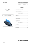
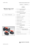
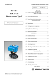
9. Make sure that O-ring(A) is mounted.
10. Tighten union nut by hand.
11. Using a strap wrench tighten union nuts
uniformly on each side approx 90 -180 , 1/4
to 1/2 turns.
3
※This figure is Spigot End
Spigot End
10. 11.
9.
O-Ring(A)
ASAHI AV VALVES
For the Owner and the Installing Contractor
ASAHI
User's Guide
Serial No. :UA-001E
Option
<Panel Mounting>
<Locking Device (Option)>
Refer to the User's manual for Metal Insert (Ensat) by Maker.
15-50mm (1/2"-2") 65-100mm (2 1/2"-4")
The handle lock can be done by full-open
(close). Refer to the User's manual for
Locking Device (Option).
Schematic Metal Insert (Ensat)
Handling of Residual and Waste Materials
㪮㪸㫉㫅㫀㫅㪾
Make sure to consult a waste treatment dealer for recommendations on the proper disposal of plastic valves.
(Poisonous gas is generated when the valve is burned improperly.)
Product Warranty
Be sure to read the following description of our product warranty.
- Always observe the specifications of and the precautions and instructions on using our product.
- We always strive to improve product quality and reliability, but cannot guarantee perfection. Therefore, should you intend
to use this product with any equipment or machinery that may pose the risk of serious or even fatal injury, or property
damage, ensure an appropriate safety design or take other measures with sufficient consideration given to possible problems. We shall assume no responsibility for any inconvenience stemming from any action on your part without our written
consent in the form of specifications or other documented approval.
- The related technical documents, operation manuals, and other documentation prescribe precautions on selecting, constructing, installing, operating, maintaining, and servicing our products. For details, consult with our nearest distributor or
agent.
- Our product warranty extends for one and a half years after the product is shipped from our factory or one year after the
product is installed, whichever comes first. Any product abnormality that occurs during the warranty period or which is
reported to us will be investigated immediately to identify its cause. Should our product be deemed defective, we shall assume the responsibility to repair or replace it free of charge.
- Any repair or replacement needed after the warranty period ends shall be charged to the customer.
- The warranty does not cover the following cases:
(1) Using our product under any condition not covered by our defined scope of warranty.
(2) Failure to observe our defined precautions or instructions regarding the construction, installation, handling, maintenance, or servicing of our product.
(3) Any inconvenience caused by any product other than ours.
(4) Remodeling or otherwise modifying our product by anyone other than us.
(5) Using any part of our product for anything other than the intended use of the product.
(6) Any abnormality that occurs due to a natural disaster, accident, or other incident not stemming from something inside
our product.
Inquiries
As for details, refer to the User's manual (No.H-V027).
http:www.asahi-yukizai.co.jp/en
Valves and Piping System Administration
Overseas Department: (World Trade Center Bldg. 20F) 4-1, Hamamatsu-cho-2- Chome, Minatoku, Tokyo, Japan. Tel : (81) 3-3578-6015 Fax : (81) 3-3578-6025
Tel : (66) 2-665-9938 Fax : (66) 2-665-9939
Bangkok Representative Office: 50 GMM Grammy Place Tower, 15th Floor, Sukhumvit 21 Road (Asoke), North Klongtoey, Wattana, Bangkok 10110, Thailand.
Europe Representative Office: Kaiser-Friedrich-Promenade 61 D-61348 Bad Homburg v. d. H. Germany.
Tel : (49) 6172-9175-0 Fax : (49) 6172-9175-25
Shanghai Branch Office: RM. 1305. Orient International Plaza Part(C) No.85 Lou Shan Guan Road, Shanghai China 200336
Tel : (21) 6278-7862
ASAHI /AMERICA Inc.: 35 Green Street P.O.Box 653 , Malden, Massachusetts 02148 U.S.A.
Tel : (1) 781-321-5409 Fax : (1) 781-321-4421
Information in this manual is subject to change without notice.
4
Fax : (21) 6278-7892
201107-(9)