1
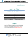
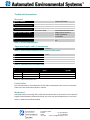
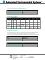
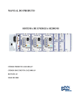
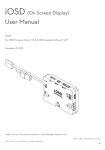
MAINS
SEPARATOR ALARM
20b Highbury Road
Brandon
Tel: 0845 8035581
Suffolk
Fax: 0845 8035582
IP27 0ND
Email: [email protected]
Separator Alarm
Installation, Operation and Maintenance
Contents
IMPORTANT . . ......................................................................................................................... 3
General Description . . ............................................................................................................. 4
General Operation. . ................................................................................................................ 4
Changing Factory Settings . . .................................................................................................... 4
Alarm Type. . ...................................................................................................................... 4
Check Interval . . ................................................................................................................. 5
Testing the Probe Sensors . . .................................................................................................... 5
Installation . . ........................................................................................................................... 5
Control Unit . . .................................................................................................................... 5
Probes (High Oil & High Liquid Level Probes) . ................................................................... 5
Silt Probe . . ........................................................................................................................ 6
Cable Distribution Box . . .................................................................................................... 6
Connection to Control Unit . . ............................................................................................. 6
Using a Junction Box . . ....................................................................................................... 6
Maintenance and Repair . . ...................................................................................................... 6
Technical Information . . .......................................................................................................... 7
Electrical . . ......................................................................................................................... 7
Apparatus Supply and I/O Parameters. ............................................................................. 7
Probe Cables . . ................................................................................................................... 7
Mechanical . . ..................................................................................................................... 7
Probe Enable Jumper Links. . ................................................................................................... 8
Probe Cable Terminals . . .................................................................................................... 9
Flashing Beacon Wiring . . ................................................................................................... 9
Accessories . . ......................................................................................................................... 10
20b Highbury Road
Brandon
Tel: 0845 8035581
Suffolk
Fax: 0845 8035582
IP27 0ND
Email: [email protected]
Separator Alarm
Installation, Operation and Maintenance
Separator Alarm
Installation, Operation & Maintenance
European Directive
Equipment Name and Type
Certificate Number
Specific Marking of Explosion Protection
ATEX Directive Marking
Notified Body
CE Mark with Notified Body Number
Harmonised Standards Used
Serial Number and Year of Manufacture
94/9/EC
Separator Monitor Type 14300
Baseefa 08ATEX0110/1
[Ex ia] IIC (-20°C ≤ Ta ≤ +50°C)
Ex II (1) G
Baseefa 1180 Buxton UK
CE1180
EN 60079-0:2006 EN 60079-11:2007
Displayed underneath the control unit
IMPORTANT
Note: In all cases good, standard electrical practice should be followed, and the installation
must conform to the appropriate local code of practice – e.g. BS EN 60079-25 in the UK. In
essence, the installation must be such that the intrinsic safety is not compromised by: exposure to risk of mechanical damage, unauthorised modification or interference,
exposure to moisture, dust and foreign bodies, excessive heat, invasion of intrinsically safe
circuit by other electrical equipment or circuitry. (See Note in installation section)
20b Highbury Road
Brandon
Tel: 0845 8035581
Suffolk
Fax: 0845 8035582
IP27 0ND
Email: [email protected]
General Description
The standard system is supplied complete with an intrinsically safe control unit together
with a high oil probe. The control unit is capable of monitoring up to 3 probe units,
displaying their current status via a 2 x 16 display. The output relay enables this status to be
signalled to a remote location or activate a beacon if required.
General Operation
The Control Unit monitors the condition of the connected probe units by checking their
condition every 30 minutes1, their current status is displayed on the display located on the
front of the unit. If an alarm condition is detected, a warning message is displayed followed
by notification of the alarm condition detected, e.g. *HAZARD ALERT* High Oil Alarm, the
output relay becomes de-energised and the internal buzzer is audible.
The unit then gives the option, via the display, to accept/acknowledge the alarm. On doing
so, the output relay energises, the buzzer is muted and the display instructs the user to take
the appropriate action, e.g. empty the separator. After the separator has been emptied and
refilled with water, the control unit re-scans the probe sensors attached and presuming no
alarm condition is detected, ‘All Correct’ will be displayed. If the push button is pressed
before the separator has been emptied, or it has been emptied but not refilled with water,
then the control simply scans the probe sensor(s) and reverts to the alarm condition. Please
note the output relay is de-energised on detection of any alarm condition or mains failure.
Changing Factory Settings
Alarm Type
The factory setting is STD (standard), this is where the output relay de-energises upon fault
detection and energises upon acceptance of the fault.
Alarm Type EXT (Extended) allows the relay to remain de-energised until all alarm
conditions become normal.
To enter the “Set Up” mode, firstly remove power from the unit. Whilst holding down the
Push Switch, power up the unit keeping the Push Switch depressed, after about 10 seconds
the screen will display “Set Up”, at this point release the Push Switch.
The display will now show Alarm Type: with a flashing cursor over STD, to change this
function to EXT, press the Push Switch once.
1
The unit is factory set to 30 minutes, but in extreme conditions, this can be manually changed from 2 to
60 minutes at one minute intervals. (see Changing Factory Settings)
20b Highbury Road
Brandon
Suffolk
IP27 0ND
Check Interval
Whilst still in the Set Up mode, power down and then power up the unit, the flashing cursor
will now be next to Check Intvl: - by pressing the Push Switch, the time can be altered in
increments of 1 minute between 2 and 60.
To exit the Set Up mode at any time, hold the Push Switch whilst powering down and then
power up again before releasing the Switch, this will return to the main screen sequence.
Testing the Probe Sensors
The probe interrogation function can be activated at any time by simply pressing the push
switch.
Installation
This product has been designed and certified as being intrinsically safe. It is of paramount
importance, that the unit should not be modified in any way and the installation be carried
out by an approved installer, in accordance with the Environment Agency guidelines (PPG3).
Any deviation from this could invalidate the certification warranty and render the unit
unsafe for its intended use.
Upon powering up the unit for the first time, the LCD will display the following message:
HAZARDOUS AREA EQUIPMENT
ACTIVATION CODE REQUIRED
The unit will not be able to function without the code which can be obtained by calling.
Control Unit
Refer to Table 4 on page 7 for required cable specifications.
The control unit must be positioned in a non-hazardous area. For all wiring details, refer to
Figure 1, Table 5 and Table 6 on page 9.
Probes (High Oil & High Liquid Level Probes)
The high oil probe is to be installed in the separator tank such that the float housing is
below the static liquid level. If a high liquid probe is required, this needs to be installed such
that the float switch housing is located above the static liquid level. Both probe cables can
be secured inside the neck of the separator using a probe cord guide.
Please note the distance above or below the static liquid level will be determined by the
type, style and/or size of separator, this information can be obtained from the separator
manufacturer. However, as a general rule of thumb, the high liquid level probe should be
placed 300mm above the static liquid level and the high oil probe 150mm below.
20b Highbury Road
Brandon
Tel: 0845 8035581
Suffolk
Fax: 0845 8035582
IP27 0ND
Email: [email protected]
Due to the varying neck lengths (turrets) that occur within each separator, each normal
probe unit is fitted with 5 metres of cable.
Silt Probe
The probe is suspended in the separator to a pre determined depth and the cable can be
secured to the neck of the separator using a probe cord guide.
Cable Distribution Box
It is advisable to connect the probe cables to a cable distribution box which should be fixed
near to the top of the separator neck. The probe cable can then be terminated with a
waterproof plug (provided with the distribution box). The plug is then connected to the
bulkhead socket (provided with the distribution box). A cable must then be laid to connect
the distribution box and the control unit. The type of connection cable required will be
dependent on the environment it is used in, the route taken and maximum allowable cable
capacitance and inductance (see cable parameters in Table 4 on page 7).
After making the connections in the distribution box, it is advisable to spray the terminals
with a conformal coating lacquer to prevent moisture ingress before finally sealing them
with waterproof putty.
Connection to Control Unit
The Probe cable should be fed through the appropriate gland in the bottom right hand side
of the control unit and connected to the terminals as instructed. The mains cable, and if
used, any beacon or sounder cable, must be fed through the appropriate gland on the
bottom left hand side of the control unit and connected to the terminals as instructed.
IMPORTANT NOTE: Under NO circumstances must the control unit casing be drilled to
allow cable entry in any area(s) other than those already provided, as this would infringe
the certification and therefore safety of the product.
Using a Junction Box
An intrinsically safe junction box should be used where incoming cable sizes have to be
reduced to gain entry through the cable glands in the base of the control unit.
IMPORTANT NOTE: Under NO circumstances must mains and probe cable joints be made
within the same junction box other than a junction box that is approved Intrinsically safe
for such purpose, as this would infringe the certification and therefore safety of the
installed system.
Maintenance and Repair
Due to the harsh environments which the probes can be subjected to, it is advised that they
are inspected and cleaned with a damp cloth at regular intervals. The control unit does not
contain user serviceable parts.
20b Highbury Road
Brandon
Tel: 0845 8035581
Suffolk
Fax: 0845 8035582
IP27 0ND
Email: [email protected]
Technical Information
Electrical
Supply Voltage
Input Current
Fusing
Normal condition
Alarm condition
Primary (FS2)
Secondary (FS3)
Max probe cable length
Relay Output
230V ±10% 50Hz
41mA
40mA
T 315mA H 250V
50mA (Baseefa approved)
200m (less if values in
Table 4 would be
exceeded)
Volt-free SPCO contact
3A
Table 1 – Electrical Specifications
Apparatus Supply and I/O Parameters
Um
253Vrms
Table 2 – Mains Supply and Relay Contact Terminals (TB2 & TB3)
Uo
Io
Po
Ci
Li
Table 3 – Hazardous Area Terminals (TB1)
Group
Capacitance (µF)
IIC
1.15
IIB
7.4
IIA
27
Table 4 – TB1 Load Parameters
12.6V
87mA
273mW
0
0
Inductance
(mH)
4.6
18.7
37.5
OR
L/R Ratio
(µH/Ω)
74
298
596
Probe Cables
The total capacitance and inductance of the cable used between the control unit and the
probe must not exceed that shown in Table 4.
Mechanical
Protection and/or screening of the cable should also be taken into account. The maximum
length of cable between probe and control unit must not exceed 200 metres or less if the
values in Table 4 would be exceeded.
20b Highbury Road
Brandon
Tel: 0845 8035581
Suffolk
Fax: 0845 8035582
IP27 0ND
Email: [email protected]
SLT
LQD
OIL
Probe Enable Jumper Links
SLT
LQD
OIL
JUMPER LINKS
RELAY
OUTPUT
PROBE INPUT
A
B
OIL
C
D
E
LIQUID
F
G
H
SILT
NC COM NO
MAINS INPUT
L
N
L
N
OUT
IN
230V AC
E
PCB-1006
SIGNAL CABLES
RELAY
OUTPUT
CABLE
Figure 1 - Probe enable jumper links
20b Highbury Road
Brandon
Tel: 0845 8035581
Suffolk
Fax: 0845 8035582
IP27 0ND
Email: [email protected]
MAINS
CABLE
To operate a probe, REMOVE appropriate jumper link
Probe Type
High Oil
High Liquid
Silt
Table 5 – Probe enable jumper links
Remove Link
OIL
LQD
SLT
Probe Cable Terminals
Probe
Type
A
B
High Oil
RED
BLUE
High
Liquid
Liquid
(Optical)
C
D
E
-
RED
BLUE
BROWN
GREEN/
YELLOW
BLUE
Silt
F
G
H
BROWN
GREEN/
YELLOW
BLUE
Table 6 - Probes cable wiring connection details
Flashing Beacon Wiring
The relay output terminals, TB2, may be used to operate a 230V flashing beacon when an
alarm occurs. The beacon should be wired according to Table 7 and Table 8. Any
commoning of live and neutral connections must be done externally to the unit’s enclosure.
TB2 Terminal
Connect To
NO
No Connection
COM
TB3 Mains live
NC
Beacon Live Terminal
Table 7 – wiring from relay output to beacon
TB3 Mains Terminal
Connect To
L out
TB2 COM Terminal
N out
Beacon Neutral Terminal
E
Mains earth
Table 8 – wiring to beacon from relay output
20b Highbury Road
Brandon
Tel: 0845 8035581
Suffolk
Fax: 0845 8035582
IP27 0ND
Email: [email protected]
Accessories
Part No.
High Oil Probe (conductivity) ---------------------------------------------------
14200
High Level Probe ------------------------------------------------------------------
14210
Silt Probe -----------------------------------------------------------------------------
14220
230 VAC Flashing Amber Beacon
(Includes mounting bracket and glands) ---------------------------------------
14012
230 VAC Flashing Amber Beacon & Siren
(Includes mounting bracket and glands) --------------------------------------
14100
Probe Cord Guide ------------------------------------------------------------------
14103
Signal Distribution Box -----------------------------------------------------------
14039
Intrinsically Safe Junction Box (Power & Probe) ---------------------------
14006
20b Highbury Road
Brandon
Tel: 0845 8035581
Suffolk
Fax: 0845 8035582
IP27 0ND
Email: [email protected]