1
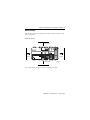
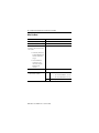
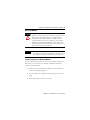
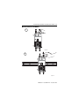
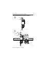
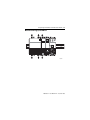
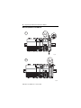
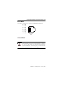
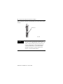
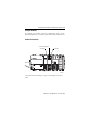
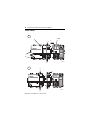
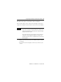
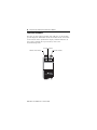
Installation Instructions
CompactLogix EtherNet/IP Communication
Module
Catalog Number 1768-ENBT
Contents
For
See Page
Before You Begin
7
Minimum Spacing
7
What You Need
8
Install Your Modules
9
Wire the Module
15
Connect the Module
15
Confirm Your Installation
17
Remove a Module
18
Configure the Module
17
Troubleshoot the Module
20
Specifications
23
Additional Resources
25
Publication 1768-IN002A-EN-P - December 2005
2 CompactLogix EtherNet/IP Communication Module
Important User Information
Solid state equipment has operational characteristics differing from those of electromechanical
equipment. Safety Guidelines for the Application, Installation and Maintenance of Solid State Controls
(Publication SGI-1.1 available from your local Rockwell Automation sales office or online at
http://www.literature.rockwellautomation.com) describes some important differences between solid
state equipment and hard-wired electromechanical devices. Because of this difference, and also
because of the wide variety of uses for solid state equipment, all persons responsible for applying this
equipment must satisfy themselves that each intended application of this equipment is acceptable.
In no event will Rockwell Automation, Inc. be responsible or liable for indirect or consequential damages
resulting from the use or application of this equipment.
The examples and diagrams in this manual are included solely for illustrative purposes. Because of the
many variables and requirements associated with any particular installation, Rockwell Automation, Inc.
cannot assume responsibility or liability for actual use based on the examples and diagrams.
No patent liability is assumed by Rockwell Automation, Inc. with respect to use of information, circuits,
equipment, or software described in this manual.
Reproduction of the contents of this manual, in whole or in part, without written permission of Rockwell
Automation, Inc., is prohibited.
Throughout this manual, when necessary, we use notes to make you aware of safety considerations.
WARNING
IMPORTANT
ATTENTION
Identifies information about practices or circumstances that can cause an explosion in
a hazardous environment, which may lead to personal injury or death, property
damage, or economic loss.
Identifies information that is critical for successful application and understanding of
the product.
Identifies information about practices or circumstances that can lead to personal
injury or death, property damage, or economic loss. Attentions help you to identify a
hazard, avoid a hazard, and recognize the consequences.
SHOCK HAZARD
Labels may be located on or inside the equipment, for example, a drive or motor, to
alert people that dangerous voltage may be present.
BURN HAZARD
Labels may be located on or inside the equipment, for example, a drive or motor, to
alert people that surfaces may be dangerous temperatures.
Publication 1768-IN002A-EN-P - December 2005
CompactLogix EtherNet/IP Communication Module 3
Environment and Enclosure
ATTENTION
This equipment is intended for use in a Pollution Degree 2
industrial environment, in overvoltage Category II applications
(as defined in IEC publication 60664-1), at altitudes up to 2000
meters without derating.
This equipment is considered Group 1, Class A industrial
equipment according to IEC/CISPR Publication 11. Without
appropriate precautions, there may be potential difficulties
ensuring electromagnetic compatibility in other environments
due to conducted as well as radiated disturbance.
This equipment is supplied as open-type equipment. It must be
mounted within an enclosure that is suitably designed for those
specific environmental conditions that will be present and
appropriately designed to prevent personal injury resulting from
accessibility to live parts. The enclosure must have suitable
flame-retardant properties to prevent or minimize the spread of
flame, complying with a flame spread rating of 5VA, V2, V1, V0
(or equivalent) if non-metallic. The interior of the enclosure must
be accessible only by the use of a tool. Subsequent sections of
this publication may contain additional information regarding
specific enclosure type ratings that are required to comply with
certain product safety certifications.
Besides this publication, see:
• Industrial Automation Wiring and Grounding Guidelines,
publication 1770-4.1, for additional installation
requirements.
• NEMA Standards publication 250 and IEC publication 60529,
as applicable, for explanations of the degrees of protection
provided by different types of enclosure.
Publication 1768-IN002A-EN-P - December 2005
4 CompactLogix EtherNet/IP Communication Module
Prevent Electrostatic Discharge
ATTENTION
This equipment is sensitive to electrostatic discharge,
which can cause internal damage and affect normal
operation. Follow these guidelines when you handle this
equipment:
• Touch a grounded object to discharge potential static.
• Wear an approved grounding wriststrap.
• Do not touch connectors or pins on component
boards.
• Do not touch circuit components inside the
equipment.
• If available, use a static-safe workstation.
• When not in use, store the equipment in appropriate
static-safe packaging.
Publication 1768-IN002A-EN-P - December 2005
CompactLogix EtherNet/IP Communication Module 5
North American Hazardous Location Approval
The following information applies when operating this
equipment in hazardous locations:
Products marked “CL I, DIV 2, GP A, B, C, D” are suitable for use in
Class I Division 2 Groups A, B, C, D, Hazardous Locations and
nonhazardous locations only. Each product is supplied with markings
on the rating nameplate indicating the hazardous location
temperature code. When combining products within a system, the
most adverse temperature code (lowest “T” number) may be used to
help determine the overall temperature code of the system.
Combinations of equipment in your system are subject to
investigation by the local Authority Having Jurisdiction at the time of
installation.
WARNING
EXPLOSION HAZARD
• Do not disconnect equipment unless power has been
removed or the area is known to be nonhazardous.
• Do not disconnect connections to this equipment
unless power has been removed or the area is
known to be nonhazardous. Secure any external
connections that mate to this equipment by using
screws, sliding latches, threaded connectors, or other
means provided with this product.
• Substitution of components may impair suitability for
Class I, Division 2.
• If this product contains batteries, they must only be
changed in an area known to be nonhazardous.
Publication 1768-IN002A-EN-P - December 2005
6 CompactLogix EtherNet/IP Communication Module
Informations sur l'utilisation de cet équipement en
environnements dangereux:
Les produits marqués "CL I, DIV 2, GP A, B, C, D" ne conviennent
qu'à une utilisation en environnements de Classe I Division 2
Groupes A, B, C, D dangereux et non dangereux. Chaque produit est
livré avec des marquages sur sa plaque d'identification qui indiquent
le code de température pour les environnements dangereux. Lorsque
plusieurs produits sont combinés dans un système, le code de
température le plus défavorable (code de température le plus faible)
peut être utilisé pour déterminer le code de température global du
système. Les combinaisons d'équipements dans le système sont
sujettes à inspection par les autorités locales qualifiées au moment de
l'installation.
AVERTISSEMENT
RISQUE D'EXPLOSION
• Couper le courant ou s'assurer que
l'environnement est classé non dangereux avant
de débrancher l'équipement.
• Couper le courant ou s'assurer que
l'environnement est classé non dangereux avant
de débrancher les connecteurs. Fixer tous les
connecteurs externes reliés à cet équipement à
l'aide de vis, loquets coulissants, connecteurs
filetés ou autres moyens fournis avec ce produit.
• La substitution de composants peut rendre cet
équipement inadapté à une utilisation en
environnement de Classe I, Division 2.
• S'assurer que l'environnement est classé non
dangereux avant de changer les piles.
Publication 1768-IN002A-EN-P - December 2005
CompactLogix EtherNet/IP Communication Module 7
Before You Begin
Plan for this minimum spacing from enclosure walls, wireways, and
other equipment.
Minimum Spacing
105 mm (4 in.)
90 mm
(3.54 in.)
90 mm
(3.54 in.)
Power
OUT
L1
L2/N
105 mm (4 in.)
31609-M
See Specifications on page 23 for the temperature range.
Publication 1768-IN002A-EN-P - December 2005
8 CompactLogix EtherNet/IP Communication Module
What You Need
Item
Catalog Number or Size
1768 CompactLogix power supply
1768-PA3
1768 CompactLogix controller
1768-L43
1769 end cap
Connects to the controller as the
last module:
1769-ECR
• without any 1769-series
modules attached to the
controller (1768-series
only), or
• with a combination
of1768-series and
1769-series modules
attached to the
controller
RJ-45 Ethernet connector
See Wire the Module on page 15
DIN rail or mounting screws (one
or the other but not both)
DIN rail
Either of these sizes:
• 35 x 7.5 mm (EN 50 022 - 35 x 7.5)
• 35 x 15 mm (EN 50 022 - 35 x 15)
Screws
M4 or #8 panhead screws
Publication 1768-IN002A-EN-P - December 2005
CompactLogix EtherNet/IP Communication Module 9
Install Your Modules
ATTENTION
IMPORTANT
This product is grounded through the DIN rail to chassis
ground. Use zinc-plated yellow-chromate steel DIN rail to
assure proper grounding. The use of other DIN rail
materials (for example, aluminum or plastic) that can
corrode, oxidize, or are poor conductors, can result in
improper or intermittent grounding. Secure DIN rail to
mounting surface approximately every 200 mm (7.87 in.)
and use end-anchors appropriately.
Do not use screws and DIN rail to mount the modules.
It is possible to break the mounting tabs off if you screw
the modules to the panel while they are on DIN rail
If You Are Using Screws to Mount Your Modules
The steps in these instructions show how to mount the modules on
DIN rail. If you are using screws instead of DIN rail, make these
changes to the instructions:
1. Follow the steps in Mount the Controller on the DIN Rail to
connect the modules together.
2. Use the modules as a template and mark pilot holes on your
panel.
3. Drill the pilot holes for M4 or #8 screws.
Publication 1768-IN002A-EN-P - December 2005
10 CompactLogix EtherNet/IP Communication Module
4. Use M4 or #8 screws to mount the modules to your panel. Use
1.16 Nm (10 lb-in) of torque.
5. Ground the module on a Ground Bus with a dedicated Earth
Ground stake.
6. Connect the Ground Bus to a Functional Earth ground on the
DIN rail or panel.
Refer to Industrial Automation Wiring and Grounding
Guidelines, Allen-Bradley publication 1770-4.1, for additional
information.
Install the DIN Rail
Mount the DIN rail in a suitable location.
Publication 1768-IN002A-EN-P - December 2005
CompactLogix EtherNet/IP Communication Module 11
Mount the Controller on the DIN Rail
1
31595-M
2
31596 -M
Publication 1768-IN002A-EN-P - December 2005
12 CompactLogix EtherNet/IP Communication Module
Mount the EtherNet/IP Communication Module on the DIN Rail
1
31597-M
2
b
a
c
Publication 1768-IN002A-EN-P - December 2005
31598 -M
CompactLogix EtherNet/IP Communication Module 13
Mount the Power Supply on the DIN Rail
31599-M
Publication 1768-IN002A-EN-P - December 2005
14 CompactLogix EtherNet/IP Communication Module
Mount the I/O Modules on the DIN Railt
a
1
b
d
c
31600-M
b
2
c
a
31601-M
Publication 1768-IN002A-EN-P - December 2005
CompactLogix EtherNet/IP Communication Module 15
Wire the Module
Use an RJ-45 connector to connect to the EtherNet/IP network.
8 ------ NC
7 ------ NC
6 ------ RD8
5 ------ NC
4 ------ NC
3 ------ RD+
1
2 ------ TD1 ------ TD+
RJ 45
Connect the Module
WARNING
If you connect or disconnect the cable with power applied
to this module or any device on the network, an electrical
arc can occur. This could cause an explosion in hazardous
location installations. Be sure that power is removed or the
area is nonhazardous before proceeding.
Publication 1768-IN002A-EN-P - December 2005
16 CompactLogix EtherNet/IP Communication Module
Attach the RJ-45 connector to the Ethernet port on the bottom of the
module.
Ethernet Port
31611-M
IMPORTANT
We recommend connecting the module to the
network via a 100MB Ethernet switch, which will
reduce collisions and lost packets and increase
network bandwidth. For detailed EtherNet/IP
connection information, see the EtherNet/IP
Modules in Logix5000 Control Systems User
Manual, publication ENET-UM001.
Publication 1768-IN002A-EN-P - December 2005
CompactLogix EtherNet/IP Communication Module 17
Configure the Module
To configure your module, refer to the configuration chapter of your
EtherNet/IP Modules User Manual, publication number ENET-UM001.
Confirm Your Installation
Solid or Flashing Green
Solid Green
Solid Green
Power
OUT
L1
L2/N
31608-M
See Troubleshoot the Module on page 20 if the lights are in other
states.
Publication 1768-IN002A-EN-P - December 2005
18 CompactLogix EtherNet/IP Communication Module
Remove a Module
1
c - Off
b
d
f
Power
OUT
L1
L2/N
a
31602-M
e
2
a
c
Power
OUT
L1
L2/N
b
Publication 1768-IN002A-EN-P - December 2005
31607-M
CompactLogix EtherNet/IP Communication Module 19
Why Wait for the Lights to Turn Off Before I Remove a Module?
After you turn off the power, wait for all of the lights on the power
supply and controller to turn off before you disconnect any modules.
IMPORTANT
When you turn the CompactLogix power supply off,
make sure you wait for all status indicators on the power
supply and controller to turn off before disconnecting
any part from the system.
If you disconnect the CompactLogix system while the
controller is still writing its program to memory, the
program write will not be completed and you will lose
your program.
• When you turn off the power, the controller writes its project
to memory.
• If you don’t wait for the lights to turn off, you will lose your
project.
Publication 1768-IN002A-EN-P - December 2005
20 CompactLogix EtherNet/IP Communication Module
Troubleshoot the Module
The three bi-color (red/green) LED status indicators on the module
provide diagnostic information about the module and its connections
to the network. If the alphanumeric display and LED indicators do
not sequence through the expected states, refer to the
troubleshooting tables.
Link Status Indicator
Network Status Indicator
Publication 1768-IN002A-EN-P - December 2005
OK Status Indicator
CompactLogix EtherNet/IP Communication Module 21
NET (Network) Status Indicator
The Network Status LED provides the following information:
State
Status
Description
Off
Not Powered,
No IP Address
Module is not powered, or does not
have an IP address.
• Verify there is chassis power
and the module is completely
inserted into the chassis and
backplane.
• Make sure the module has
been configured.
Flashing Green
No Connections
Module has obtained an IP address,
but has no established connections.
Green
CIP Connections
Module has an IP address and at least
one established connection.
Flashing Red
Connection Timeout
One or more of the connections in
which the module is the target has
timed out.
Red
Duplicate IP Address
Module has detected that its IP
address is already in use. Assign a
unique IP address to the module.
Link Status Indicator
The Link Status LED provides the following information:
State
Status
Description
Off
No data transmission
Module is not ready to communicate.
Green
Ready
Module is ready to communicate.
Flashing Green
Data transmission in
progress
Module is communicating over the
network.
Publication 1768-IN002A-EN-P - December 2005
22 CompactLogix EtherNet/IP Communication Module
OK Status Indicator
The OK Status LED provides the following module information:
State
Status
Description
Off
No Power
Module does not have 5V dc power.
Verify there is power and the module is
properly installed.
Flashing Green
Standby
Module is not configured.
Green
Operational
Module is operating correctly.
Flashing Red
Minor Fault
A recoverable fault has been detected.
This could be caused by an error in the
configuration.
Red
Major Fault
An unrecoverable fault has been
detected. Recycle power to the module.
If this does not clear the fault, replace
the module.
Flashing Red and Green Self-test
Module performing power-up self-test.
Where to Find Information on Configuring the Module
To configure your module, refer to the EtherNet/IP Modules in
Logix5000 Control Systems User Manual, publication ENET-UM001.
Publication 1768-IN002A-EN-P - December 2005
CompactLogix EtherNet/IP Communication Module 23
Specifications
1768-ENBT CompactLogix EtherNet/IP Communication Module
Attribute
Value
Backplane Current (mA)
at 5 V
834 mA
Power Consumption
4.38 W
Power Dissipation
4.38 W
Isolation (continuous-voltage
rating)
30V, Functional Insulation Type, Ethernet to system
Tested at 710Vdc for 60 seconds, Ethernet to system
Wiring Category(1)
2 - on communications ports
North American Temp Code
T4A
Mounting Screw Torque
1.16 Nm (10 lb-in), using M4 or #8 screws
Dimensions (HxWxD), Approx.
132 x 56.7 x 105.1 mm (5.20 x 2.23 x 4.12 in.)
Weight, Approx.
0.213 kg (7.5 oz)
(1)
Use this Conductor Category information for planning conductor routing. Refer to Industrial
Automation Wiring and Grounding Guidelines, publication 1770-4.1.
Environmental Specifications
Attribute
Value
Operating Temperature
IEC 60068-2-1 (Test Ad, Operating Cold),
IEC 60068-2-2 (Test Bd, Operating Dry Heat),
IEC 60068-2-14 (Test Nb, Operating Thermal Shock):
0...60 °C (32...140 °F)
Nonoperating
Temperature
IEC 60068-2-1 (Test Ab, Unpackaged Nonoperating Cold),
IEC 60068-2-2 (Test Bb, Unpackaged Nonoperating Dry Heat),
IEC 60068-2-14 (Test Na, Unpackaged Nonoperating Thermal Shock):
-40...85 °C (-40...185 °F)
Relative Humidity
IEC 60068-2-30 (Test Db, Unpackaged Damp Heat):
5...95% non-condensing
Vibration
IEC 60068-2-6 (Test Fc, Operating):
5 g @ 10...500 Hz
Operating Shock
IEC 60068-2-27 (Test Ea, Unpackaged Shock):
30 g
Publication 1768-IN002A-EN-P - December 2005
24 CompactLogix EtherNet/IP Communication Module
Environmental Specifications
Attribute
Value
Nonoperating Shock
IEC 60068-2-27 (Test Ea, Unpackaged Shock):
50 g
Emissions
CISPR 11:
Group 1, Class A
ESD Immunity
IEC 61000-4-2:
4 kV contact discharges
8 kV air discharges
Radiated RF Immunity
IEC 61000-4-3:
10V/m with 1 kHz sine-wave 80%AM from 30…2000 MHz
10V/m with 200 Hz 50% Pulse 100%AM at 900 MHz
10V/m with 200 Hz 50% Pulse 100%AM at 1890 MHz
1V/m with 1 kHz sine-wave 80%AM from 2000…2700 MHz
EFT/B Immunity
IEC 61000-4-4:
±2 kV at 5 kHz on communication ports
Surge Transient Immunity
IEC 61000-4-5:
±2 kV line-earth(CM) on communication ports
Conducted RF Immunity
IEC 61000-4-6:
10V rms with 1 kHz sine-wave 80%AM from 150 kHz…80 MHz
Enclosure Type Rating
None (open-style)
Certifications
Certification (when
Value
product is marked)(1)
c-UL-us
UL Listed Industrial Control Equipment, certified for US and Canada.
See UL File E65584.
UL Listed for Class I, Division 2 Group A,B,C,D Hazardous Locations,
certified for U.S. and Canada. See UL File E194810.
Publication 1768-IN002A-EN-P - December 2005
CompactLogix EtherNet/IP Communication Module 25
Certifications
Certification (when
Value
product is marked)(1)
CE
EN 50082-2; Industrial Immunity
EN 61326; Meas./Control/Lab., Industrial Requirements
EN 61000-6-2; Industrial Immunity
EN 61000-6-4; Industrial Emissions
EN 61131-2; Programmable Controllers (Clause 8, Zone A & B)
C-Tick
Australian Radiocommunications Act, compliant with:
AS/NZS CISPR 11; Industrial Emissions
EtherNet/IP
ODVA conformance tested to EtherNet/IP specifications
(1)
See the Product Certification link at www.ab.com for Declarations of Conformity, Certificates, and
other certification details.
Additional Resources
Publication
Publication Number
EtherNet/IP Modules in Logix5000 Control
Systems User Manual
ENET-UM001
1768 CompactLogix Power Supplies
Installation Instructions
1768-IN001
CompactLogix Controller Installation
Instructions
1768-IN004
CompactLogix Controller User Manual
1768-UM001
Allen-Bradley, CompactLogix, and Logix5000 are trademarks of Rockwell Automation, Inc.
Trademarks not belonging to Rockwell Automation are property of their respective companies.
Publication 1768-IN002A-EN-P - December 2005
26 CompactLogix EtherNet/IP Communication Module
Notes:
Publication 1768-IN002A-EN-P - December 2005
CompactLogix EtherNet/IP Communication Module 27
Notes:
Publication 1768-IN002A-EN-P - December 2005
Rockwell Automation Support
Rockwell Automation provides technical information on the web to assist you
in using its products. At http://support.rockwellautomation.com, you can find
technical manuals, a knowledge base of FAQs, technical and application
notes, sample code and links to software service packs, and a MySupport
feature that you can customize to make the best use of these tools.
For an additional level of technical phone support for installation,
configuration and troubleshooting, we offer TechConnect Support programs.
For more information, contact your local distributor or Rockwell Automation
representative, or visit http://support.rockwellautomation.com.
Installation Assistance
If you experience a problem with a hardware module within the first 24 hours
of installation, please review the information that's contained in this manual.
You can also contact a special Customer Support number for initial help in
getting your module up and running:
United States
1.440.646.3223 Monday – Friday, 8am – 5pm EST
Outside United States
Please contact your local Rockwell Automation representative for any
technical support issues.
New Product Satisfaction Return
Rockwell tests all of its products to ensure that they are fully operational when
shipped from the manufacturing facility. However, if your product is not
functioning and needs to be returned:
United States
Contact your distributor. You must provide a Customer Support case number
(see phone number above to obtain one) to your distributor in order to
complete the return process.
Outside United States
Please contact your local Rockwell Automation representative for return
procedure.
ö
Publication 1768-IN002A-EN-P - December 2005
Supersedes Publication XXXX-X.X.X - Month Year
PN 957974-32
Copyright © 2005 Rockwell Automation, Inc. All rights reserved. Printed in the U.S.A.