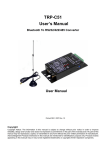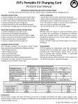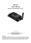
1
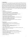
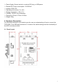
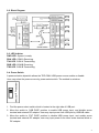
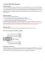
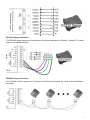
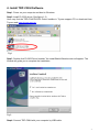
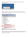
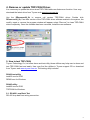
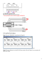
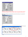
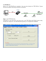
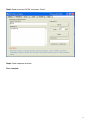
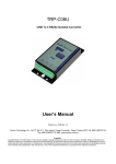
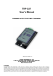
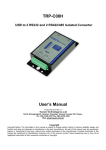
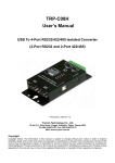
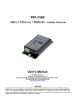
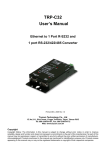
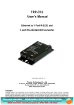
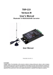
TRP-C08H
User’s Manual
USB to 2 ports RS-232 and 2 ports
RS-422/485 Isolated Converter
Printed Jun. 2007 Rev 1.1
Trycom Technology Co., Ltd
1F, No.2-11, Sihu street, Yingge Township, Taipei, Taiwan ROC
Tel: 886-2-86781191, Fax: 886-2-86781172
Web: www.trycom.com.tw
Copyright
Copyright Notice: The information in this manual is subject to change without prior notice in order to improve
reliability, design and function and dosed not represent a commitment on the part of the manufacturer. No part of this
manual may be reproduced, copied, or transmitted in any form without the prior written permission of manufacturer.
Acknowledgment Products mentioned in this manual are mentioned for identification purpose only. Products manes
appearing in this manual may or may not be registered trademarks or copyright of their respective companies.
1. Introduction
The TRP-C08H allows you to simultaneously connect 2 RS-232 and 2 RS-422/485 serial devices
to system by using a USB interface. The RS-232 interface support all common PC DTE
connection type. For RS-422/485 data lines TRP-C08H provides auto-detecting function in data
format, baud rate and data direction flow control, it may automatically configure RS-422/485
signals and baud rate without external switch setting. TRP-C08H is equipped with 3000V DC of
isolation and internal surge protection to protect the host computer and converter against high
voltage spikes, as well as ground potential differences. TRP-C08H features a high-speed 256KB
transmission rate, and supports various O.S. The industry standard DIN rail design enables
users a fast and professional installation.
1-1. Features
¾ Wide input range DC power supply.
¾ Full compliance with the USB V1.0, 1.1 and 2.0 specification.
¾ Expand to 2 standard RS-232 ports and 2 RS-422/485 ports.
¾ System gets 4 COM port when the TRP-C08H converter is connected.
¾ 256 bytes buffer for upstream and downstream data flow.
¾ Auto direction flow control on RS-485.
¾ Automatically switch signal RS422 and RS-485.
¾ Support 3000V DC isolation and surge protection on RS-422/485 data lines.
¾ Power/TXA/RXA/TXB/RXB mode LED indicator.
¾ Direct power from USB port and external power.
¾ Driver support: Windows 98/ME/2000/XP/CE3.0, and Linux, and Mac OS.
¾ DIN rail or Panel mount support.
1-2.Specifications
¾ USB interface: Fully compliant with V1.0, 2.0 specification.
¾ Dual RS-232 Output: TX, RX, RTS, CTS, DTR, DSR, And DCD, RI.
¾ Dual RS-422/485 output:
¾ RS-422 signal: Differential 4 full-duplex wires (TX+, RX+, TX-, RX-).
¾ RS-485 signal: Differential 2 half-duplex wires. (D+, D-)
¾ Cable: USB type A to type B.
¾ Data format: Asynchronous data with all common combination of bits, parity, stop
¾ Parity type: None, odd, even mark, space.
¾ Stop bits: 1, 1.5, 2.
¾ Data bit: 5, 6, 7, 8.
¾ Communication speed: form 300bps to 256Kbps auto-switching.
¾ RS-422/485 line protection: Against surge, short circuit, and voltage peak.
¾ Distance: Up to 4000ft (1200M).
¾ Connection type: Screw terminal for maximum AWG #12~30 wires.
¾ Signal LED: Power on, TXA, RXB.TXB, RXB.
¾ Din-Rail mountable: Yes.
2
¾ Power Supply: Screw terminal, or external DC plug, or USB power.
¾ External DC Power consumption: 12V/220mA.
¾ Isolation:3000V DC.
¾
¾
¾
¾
¾
Operating environment: 0 to 60℃.
Storage temperature: -20 to 70℃.
Humidity: 10-90% non-condensing.
Dimension:151mm X 75mm X 26mm.
Weight: 395g.
2. Hardware Description
The following information is provided to give the user an understanding of how to connect the
TRP-C08H to the USB and serial device. A review of the switch settings and the functionality of
the LED’s are also provided.
2-1. Panel Layout
3
2-2. Block Diagram
2-3. LED Indictor
PWR LED: System is ready.
RXA LED: COM-A Receiving.
TXA LED: COM-A Transmitting.
RXB LED: COM-B Receiving.
TXB LED: COM-B Transmitting.
2-4. Power Switch
A power selection dipswitch allows the TRP-C08H USB power source enable or disable.
User may select the power source by power select switch. The method is as below.
1. Find the power select switch which is located at the right side of USB port.
2. Move the switch to “USB PWR” position to enable USB power input, and disable screw
terminal and external DC adapter. User may input power from USB port by USB A/B cable.
3. Move the switch to “EXT PWR” position to disable USB power input, and enable screw
terminal and external DC adapter, user may input power from either screw terminal block or
DC adapter.
4
3. Install TRP-C08H Hardware
Serial Connection
The TRP-C08H has two DB-9 male and two 4-wire RS-422/485 connectors. The RS-232 serial
port is configured as a DTE (data terminal equipment) device. All PC COM ports are DTE ports. A
null modem cable is required to make a connection between TRP-C08H COM port and PC COM
portC08H serial port. A straight through cable is required to connect the TRP-C08H serial port to
a DCE device.
Power Connection
TRP-C08H supports 3 power sources
1. User may input power direct from USB port (+5V/ 220mA).
2. or from external DC plug (power jack specification. (5.5*2.1*12 mm).
3. or from a 2-pin terminal block (industry screw terminal)
TRP-C08H supports wide range DC power supply from +10-30VDC/500mA. When power is
properly supplied the PWR LED will lighting to indicate the system is up. User can only choose
one of the three power sources, do not connect different power source simultaneously.
USB Connection.
TRP-C08H uses the standard A to B type USB cable between host and converter.
RS-232 Pin Configuration (COMC and COMD) .
RS-232 wiring connection.
The RS-232 supports 8 channels plus Signal Ground and is configured as DTE like a computer.
Signals are single ended and referenced to Ground. To use handshaking, Flow Control must be
set to RTS/CTS during Configuration. Refer to the Pin out table for connections.
5
RS-422 wiring connection.
The RS-422 mode supports 4 channels with full duplex operation for Receive, Transmit, The data
lines are in differential pairs.
RS485 wiring connection.
The RS-485 mode supports the Transmit and Receive Channels by using 2-wire half-duplex
operation.
6
4. Install TRP-C08H Software
Step1. Power on your computer and boot to Windows.
Step2. Install PL-2303 driver (See figure1, 2)
User may find the TRP-C0H8 PL2303 Driver Installer in Trycom support CD or download from
Trycom web www.trycom.com.tw.
Fig.1
Step3. Double click PL2303 Driver Installer” the installShield Wizard screen will appear. The
Wizard will guide you to complete the installation.
Fig.2
Step4. Connect TRP-C08H with your computer by USB cable.
7
Step5. Windows system will auto detect 4 “new USB devices" and complete the hardware
installation.(See Fig.3)
Fig.3
Step6. After installation user may verify if TRP-C08H was properly installed by Click Start –
Setting -- Control panel -- double click system icon – Hardware Device Manager -- Double click
on ports (COM&LPT) .(See Figure 4)
Fig.4
Step7. If TRP-C08H was correctly installed you may see 4 new COM ports devices appear. This
means Windows has already assigned all 4 TRP-C08H serial ports a COM port number, and the
installation process completed.
8
4. Remove or update TRP-C08H Driver.
It is necessary to update the driver when TRP-C08H adds new features or function. User may
download the latest driver from Trycom web www.trycom.com.tw .
Use the DRemover98_2k to remove old version TRP-C08H driver. Double click
DRemover98_2k, If an older version of the TRP-C08H driver software existed in the system, the
modify, repair or remove the program window will appear, select “Remove” to clean TRP-C08H
driver completely. Once the software has been removed, install the new software.
5. How to test TRP-C08H
Trycom Technology Co.,Ltd offers demo and test utility, these utilities may help user to demo and
test TRP-C08H fast and easily. User may find the utilities in Trycom support CD or download
from Trycom web www.trycom.com.tw. The testing utility includes
RS422 test utility
test422.exe for DOS
DEMO.exe for Windows
RS485 utility.
test485.exe for DOS
TRPCOM for Windows.
5-1. RS-422 Loop Back Test
RS-422 loop back test wiring connection.
9
5-2. RS-232 Loop Back Test
RS-232 loop back test wiring connection.
* Test loop back include must be highlight “RTS/CTS”
5-3.Loop Back Test Software
Step1.Run the “DEMO.EXE” utility (See the Figure 5).
Fig.5
Step2.Click the “Setting” to set the RS-422 loop counter (See the Figure 6); your system will
detect the COM3.
10
Fig.6
* Please note: “COM3” is an example of COM port number; user may get a different COM port
number after the installation. The actual COM port number is assigned by Windows system.
Step3.Click the “Setting” to set the RS-232 loop counter (See the Figure 7); your system will
detect COM3.
Fig.7
Step4.Click the “OK” the utility will show the input and output status of RS-232(See the Figure 8).
Fig.8
11
5-4. RS-485 test.
Refer to 3-7 the RS-485 wire connection. User may also directly link TRP-C08H to Trycom
Remote IO modules, the wiring connection is as below.
Step1. Install TRPCOM utility.
TRPCOM is a test utility which may help user to test TRP-C08H with RS-485 device easily.
Double click “Setup.exe”, the install Wizard will guide you to complete the installation.
Step2. Configure COM port and baud rate, after configuration press “OK” to the next screen.
12
Step3.Send command “$01M” and press “Send”.
Step4. Data response received.
Test complete.
13