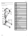
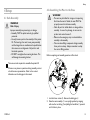
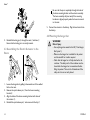
1
Invacare® Birdie™
Birdie™, Birdie™Compact
EN Portable Patient Lift
User Manual
This manual MUST be given to the user of the product.
BEFORE using this product, read this manual and save for future reference.
©2013 Invacare®Corporation
All rights reserved. Republication, duplication or modification in whole or in part is prohibited without
prior written permission from Invacare. Trademarks are identified by ™and ®. All trademarks are
owned by or licensed to Invacare Corporation or its subsidiaries unless otherwise noted.
.
.
.
.
.
17
18
18
18
20
6
Lifting the Patient. . . . . . . . . . . . . . . . . . . . . . . . . . . . . .
6.1
Safe Lifting . . . . . . . . . . . . . . . . . . . . . . . . . . . . . . . .
6.2
Preparing to Lift. . . . . . . . . . . . . . . . . . . . . . . . . . . .
6.3
Attaching the Slings to the Lift . . . . . . . . . . . . . . . . .
6.4
Lifting and Transferring the Patient . . . . . . . . . . . . . .
Floor Transfers (Lifting from the Floor) . . . . . . . . .
Commode Transfer Guidelines . . . . . . . . . . . . . . .
Bed Transfer . . . . . . . . . . . . . . . . . . . . . . . . . . . .
Wheelchair Transfer. . . . . . . . . . . . . . . . . . . . . . .
22
22
23
25
26
27
29
30
30
7
Maintenance . . . . . . . . . . . . . . . . . . . . . . . . . . . . . . . . . .
7.1
Maintenance and Safety Inspection . . . . . . . . . . . . . .
Safety inspection checklist . . . . . . . . . . . . . . . . . . .
7.2
Lubricating the Lift . . . . . . . . . . . . . . . . . . . . . . . . . .
7.3
Cleaning the Sling and Lift . . . . . . . . . . . . . . . . . . . . .
7.4
Checking and Tightening Mast Pivot Bolt . . . . . . . . . .
7.5
Checking the carabiner and its mounting . . . . . . . . . .
7.6
Replacing the Hanger Bar . . . . . . . . . . . . . . . . . . . . .
32
32
34
35
35
35
36
36
8
After Use. . . . . . . . . . . . . . . . . . . . . . . . . . . . . . . . . . . . .
8.1
Transportation and Storage . . . . . . . . . . . . . . . . . . .
8.2
Disposal . . . . . . . . . . . . . . . . . . . . . . . . . . . . . . . . .
8.3
Reuse . . . . . . . . . . . . . . . . . . . . . . . . . . . . . . . . . . .
37
37
37
37
9
Troubleshooting . . . . . . . . . . . . . . . . . . . . . . . . . . . . . . . 38
9.1
Identifying and repairing faults . . . . . . . . . . . . . . . . . . 38
Contents
1
2
General . . . . . . . . . . . . . . . . . . . . . . . . . . . . . . . . . . . . . . 5
1.1
About this manual . . . . . . . . . . . . . . . . . . . . . . . . . . 5
1.2
Intended Use . . . . . . . . . . . . . . . . . . . . . . . . . . . . . . 5
1.3
Scope of delivery . . . . . . . . . . . . . . . . . . . . . . . . . . . 6
1.4
Service Life . . . . . . . . . . . . . . . . . . . . . . . . . . . . . . . 6
1.5
Warranty Information . . . . . . . . . . . . . . . . . . . . . . . 7
Safety. . . . . . . . . . . . . . . . . . . . . . . . . . . . . . . . . . . . . . . . 8
2.1
Safety information . . . . . . . . . . . . . . . . . . . . . . . . . . 8
2.2
Operating Information . . . . . . . . . . . . . . . . . . . . . . . 8
General . . . . . . . . . . . . . . . . . . . . . . . . . . . . . . . . 8
Pinch Points and Positioning . . . . . . . . . . . . . . . . . 9
2.3
Radio Frequency Interference . . . . . . . . . . . . . . . . . . 9
2.4
Product labeling . . . . . . . . . . . . . . . . . . . . . . . . . . . . 9
3
Overview . . . . . . . . . . . . . . . . . . . . . . . . . . . . . . . . . . . . . 11
3.1
Main parts of the lift . . . . . . . . . . . . . . . . . . . . . . . . . 11
3.2
Accessories . . . . . . . . . . . . . . . . . . . . . . . . . . . . . . . 12
4
Setup . . . . . . . . . . . . . . . . . . . . . . . . . . . . . . . . . . . . . . . .
4.1
Safe Assembly . . . . . . . . . . . . . . . . . . . . . . . . . . . . .
4.2
Assembling the Mast to the Base . . . . . . . . . . . . . . . .
4.3
Assembling the Electric Actuator to the Boom . . . . . .
4.4
Mounting the hanger bar . . . . . . . . . . . . . . . . . . . . .
4.5
Disassembling of the lift . . . . . . . . . . . . . . . . . . . . . .
4.6
Checking the service light . . . . . . . . . . . . . . . . . . . . .
13
13
13
14
14
15
15
Usage . . . . . . . . . . . . . . . . . . . . . . . . . . . . . . . . . . . . . . . .
5.1
Introduction . . . . . . . . . . . . . . . . . . . . . . . . . . . . . .
5.2
Raising/Lowering the Lift . . . . . . . . . . . . . . . . . . . . .
Raising/Lowering an Electric Lift . . . . . . . . . . . . . .
5.3
Closing/Opening Legs. . . . . . . . . . . . . . . . . . . . . . . .
17
17
17
17
17
5
5.4
5.5
5.6
Closing/Opening Electric Legs .
Closing/Opening legs manually.
Performing an Emergency Stop . .
Activating an Emergency Release.
Charging the battery . . . . . . . . .
.
.
.
.
.
.
.
.
.
.
.
.
.
.
.
.
.
.
.
.
.
.
.
.
.
.
.
.
.
.
.
.
.
.
.
.
.
.
.
.
.
.
.
.
.
.
.
.
.
.
.
.
.
.
.
.
.
.
.
.
.
.
.
.
.
.
.
.
.
.
10 Technical data. . . . . . . . . . . . . . . . . . . . . . . . . . . . . . . . . 40
10.1 Dimensions and weight. . . . . . . . . . . . . . . . . . . . . . . 40
10.2 Electrical system . . . . . . . . . . . . . . . . . . . . . . . . . . . 41
10.3
10.4
10.5
Electromagnetic compliance (EMC)
information . . . . . . . . . . . . . . . . . . . . . . . . . . . . . . . 42
Environmental conditions . . . . . . . . . . . . . . . . . . . . . 42
Materials . . . . . . . . . . . . . . . . . . . . . . . . . . . . . . . . . 42
General
1 General
Tips and Recommendations
Gives useful tips, recommendations and information
for efficient, trouble-free use.
1.1 About this manual
This product complies with Directive 93/42/EEC
concerning medical devices. The launch date of this
product is stated in the CE declaration of conformity.
Thank you for choosing an Invacare product.
This user manual contains important information about the handling
of the product. In order to ensure safety when using the product,
read the user manual carefully and follow the safety instructions.
Please note that there may be sections in this user manual, which are
not relevant to your product, since this manual applies to all existing
modules (on the date of printing).
1.2 Intended Use
WARNING!
Risk of Falling
The Invacare mobile patient lift is NOT a transport
device. It is intended to transfer an individual from
one resting surface to another (such as a bed to a
wheelchair).
Invacare slings and patient lift accessories are specifically
designed to be used in conjunction with Invacare patient
lifts.
Symbols in this manual
In this user manual, warnings are indicated by symbols. The warning
symbols are accompanied by a heading that indicates the severity
of the danger.
WARNING
Indicates a hazardous situation that could result in
serious injury or death if it is not avoided.
CAUTION
Indicates a hazardous situation that could result in
minor or slight injury if it is not avoided.
IMPORTANT
Indicates a hazardous situation that could result in
damage to property if it is not avoided.
Mobile patient lifts are battery-powered transfer devices, designed to
be used in most of the common lifting situations, for example:
•
•
•
Between the bed and a wheelchair
To and from the toilet
Lowering and raising patients to/from the floor
The mobile patient lift can be used to transfer and position completely
or partially immobile patients. There are no known contraindications
for this product.
Selecting the appropriate slings and accessories for each individual is
important to assure safety when using a patient lift. See Invacare’s
sling and accessory user manuals for further information on those
devices.
1575025-A
5
Birdie™
Invacare recommends that the patient be transferred to a shower
chair or other means for bathing.
A
Lift (1 piece)
B
Battery (1 piece)
The mobile patient lift can be turned (rotated) in place for transfers
with limited floor space.
C
Hand control (1 piece)
D
Hanger bar (1 piece)
E
Mains cable (1 piece)
F
User Manual (1 piece)
G
Manual leg spreader handle (1 piece, optional)
H
Sling (1 piece, optional)
1.3 Scope of delivery
The items listed in the tables are included in your package. Slings
and additional hanger bars are sold separately. Depending on your
model, the wall charger may be sold separately.
A
1.4 Service Life
B
D
C
WARNING!
Risk of Falling
Maintenance MUST be performed only by qualified
personnel.
Improper assembly may cause injury or damage.
– Regular maintenance of patient lifts and accessories is
necessary to assure proper operation.
– DO NOT overtighten the mounting hardware. This
will damage the mounting bracket.
The hoist has an expected lifetime of 8 years.
Actuator Service Life
Number of lifts per
day
6
Service life of actuator
(in years)
1–2
10
3
9
1575025-A
General
Number of lifts per
day
Service life of actuator
(in years)
4
6
5
5
6
4
7
3
10–13
2
14–27
1
1.5 Warranty Information
Terms and conditions of the warranty are part of the general terms
and conditions particular to the individual countries in which this
product is sold.
Contact information for your local Invacare office is located inside
the back cover of this manual.
1575025-A
7
Birdie™
2 Safety
2.1 Safety information
WARNING!
– Do not use this product or any available optional
equipment without first completely reading and
understanding these instructions and any additional
instructional material such as user manuals, service
manuals or instruction sheets supplied with this
product or optional equipment. If you are unable to
understand the warnings, cautions or instructions,
contact a healthcare professional, dealer or technical
personnel before attempting to use this equipment otherwise, injury or damage may occur.
The information contained in this document is subject to
change without notice.
Check all parts for shipping damage before using. In case of damage,
Do not use the equipment. Contact the Dealer or Invacare
representative for further instructions.
2.2 Operating Information
This section of the manual contains general safety information
about your product. For specific safety information, refer to the
appropriate section of the manual and procedures within that section.
For instance, for safety information related to assembling the lift,
refer to section 4 Setup, page 13.
8
General
WARNING!
Risk of Falling
Do not attempt any transfer without approval of
the patient’s physician, nurse or medical assistant.
Thoroughly read the instructions in this User Manual,
observe a trained team of experts perform the lifting
procedures and then perform the entire lift procedure
several times with proper supervision and a capable
individual acting as a patient.
– Use common sense in all lifts. Special care must
be taken with people with disabilities who cannot
cooperate while being lifted.
– Use steering handle on the mast at all times to push or
pull the patient lift.
– Be sure to check the sling attachments each time the
sling is removed and replaced, to ensure that it is
properly attached before the patient is removed from
a stationary object (bed, chair or commode).
WARNING!
– The patient lift can be used indoors or outdoors. If
the patient lift is used in the area of a shower or
bath, ensure that the patient lift is wiped clean of any
moisture after use.
– Periodically inspect all components of the patient
lift for signs of corrosion. Replace all parts that are
corroded or damaged.
1575025-A
Safety
Pinch Points and Positioning
2.4 Product labeling
Label location
180 kg
XL
L
M
S
XS
WARNING!
Risk of Injury
Pinch points are present in several locations on the lift
and fingers could be pinched.
The hanger bar can move suddenly and cause injury.
– Always keep hands and fingers clear of moving parts.
– When positioning lift, be aware of the position of the
hanger bar and the patient.
Invacare Portugal, Lda, Rua Es trada Velha n° 949
4465-784 Leça do Balio, Portugal Tel: (351) (0) 225 1059 46/47
XXXXXX
XXXXXX
XXXXXX
MM/YYYY
XXXXX
1176077 rev C
Symbols on the label
2.3 Radio Frequency Interference
Emergency stop / Emergency release
WARNING!
– Most electronic equipment is influenced by Radio
Frequency Interference (RFI). CAUTION should
be exercised with regard to the use of portable
communication equipment in the area around such
equipment. If RFI causes erratic behavior, PUSH the
Red Power Switch OFF IMMEDIATELY. DO NOT
turn the Power Switch ON while transmission is in
progress.
Raise/lower the boom
Open/close legs
Open/close legs manually
1575025-A
9
Birdie™
Tool-less hanger bar attachment. Refer to 7.6
Replacing the Hanger Bar, page 36.
Caster lock
Audible tone when battery low. Refer to 5.6
Charging the battery, page 20.
Read Manual
Date of manufacture.
This product complies with Directive 93/42/EEC
concerning medical devices. The launch date of
this product is stated in the EC declaration of
conformity.
Safe Working Load
Class II equipment
Type B applied part
WEEE conform. Refer to 8.2 Disposal, page 37.
10
1575025-A
Overview
3 Overview
3.1 Main parts of the lift
E
F
L
I
P
H
K
J
G
M
N
Q
O
D
A
B
C
A
Base
B
Leg
C
Caster
D
Rear castor with brake
E
Boom
F
Mast
G
Hanger bar
H
Hook for sling
I
Carabiner
J
Actuator
K
Manual emergency lowering handle
L
Control unit with Battery
M
Emergency Stop
N
Hand control
O
Locking pin
P
Steering handle
Q
Foot pedal for leg spreader
Leg spreader handle (optional)
Motor for electrical operation of legs (optional)
1575025-A
11
Birdie™
3.2 Accessories
CAUTION!
Compatibility of slings and hanger bars
Invacare® uses a "Loop and Coat Hanger Bar System" as
do many other manufacturers. Therefore other suitable
patient transfer systems (slings), manufactured by other
companies, can be used on the Invacare patient lift range
as well.
However we do recommend:
– A risk assessment is always to be carried out by a
professional prior to issuing lifting equipment. It is
important that the Task, Individual, Load, Environment
and Equipment are considered in the risk assessment.
– Always choose the sling design and size according
to the clients weight, size and physical ability whilst
considering the type of transfer to be carried out.
– Do only use slings that are suitable for a "Loop and
Coat Hanger Bar System".
– Do not use slings for "Keyhole Hanger Bar" or for
"Tilting Frame Hanger Bar" designs.
12
Available accessories
•
•
•
•
4 point hanger bar (“Coat Hanger Bar System”), 45 or 55 cm
wide
2 point hanger bar (“Coat Hanger Bar System”), 35, 45 or 55
cm wide
Scale to be mounted with the hanger bar
Handle for leg spread
Sling models for "Loop and Coat Hanger Bar System":
•
•
•
•
Full body support slings – without head support
Full body support slings –with head support
Slings for dress/toileting – with or without head support
Slings for amputee
1575025-A
Setup
4 Setup
4.2 Assembling the Mast to the Base
WARNING!
– The mast may be folded for storage or transporting.
Each time the mast is folded, the mast MUST be
properly secured to the base assembly.
– Check all parts for visible defects or damage before
assembly. In case of any damage, do not use the
product and contact Invacare®.
– Make sure the emergency stop is activated before
assembly or disassembly.
– Take care when lifting components during assembly.
Some parts are heavy. Always remember to adopt
the correct lifting position.
4.1 Safe Assembly
WARNING!
Risk of Injury
Improper assembly may cause injury or damage.
– Assembly MUST be performed only by qualified
personnel.
– Use only Invacare parts in the assembly of this patient
lift. The base legs, the mast, boom, pump assembly
and the hanger bar are manufactured to specifications
that assure correct alignment of all parts for safe
functional operation.
– DO NOT overtighten the mounting hardware. This
will damage the mounting bracket.
Perform unpacking and assembly operation at floor level.
There are no tools required to assemble the patient lift.
If there are any issues or questions during assembly, contact
a local Invacare representative. Refer to the contact
information on the last page in this manual.
1.
2.
1575025-A
Lock both rear casters B. Remove the locking pin A.
Raise the mast assembly C to an upright position by stepping
with one foot on the leg D and pulling the handle bar E upwards
until it locks in place.
13
Birdie™
Be sure that the pin is completely through the holes of
the boom mounting bracket and the actuator assembly.
The boom assembly will pivot easily if the mounting
hardware is aligned properly when the boom is secured
to the mast.
5.
Connect the actuator to the battery. Plug the hand control into
the battery.
4.4 Mounting the hanger bar
3.
Reinstall the locking pin A through the mast G and base F.
Ensure that the locking pin is correctly inserted.
4.3 Assembling the Electric Actuator to the
Boom
1.
2.
3.
4.
14
WARNING!
Risk of injury
– Use only hanger bars made for this lift (“Coat Hanger
Bar System”).
– Make sure the hanger bar is suitable for the patient
and the actual lift or transfer required.
– Check that the hanger bar is firmly attached to the
carabiner. The safety catch of the carabiner must be
closed after the hanger bar is mounted and before
lifting the patient. There is risk of detachment if the
safety catch is not correctly closed.
Loosen the hanger bar by pulling it downwards out of the welded
fork on the mast.
Remove the quick release pin A from the boom mounting
bracket B.
Align the holes of the boom mounting bracket with those of
the actuator C.
Reinstall the quick release pin A and secure with the clip D.
1575025-A
Setup
1.
2.
3.
4.6 Checking the service light
( Jumbo Care control unit only)
CAUTION!
– Each time the lift is assembled, and before using the
lift, the service light should be checked.
– The service light should only be reset by a qualified
technician and must never be reset by untrained
personnel.
C
A
1.
2.
3.
B
Open the carabiner A by pushing the safety catch B backwards
with one hand.
Hold the safety catch in the open position and attach the hanger
bar C to the upper part of the carabiner with the other hand.
Release the safety catch and move the hanger bar to the lower
point of the carabiner.
A
C
4.5 Disassembling of the lift
1.
2.
3.
4.
5.
6.
Remove optional leg spreader handle if attached.
Lower the boom and narrow both legs completely.
Activate the emergency stop button and apply castor brakes.
Remove the pipe pin and the motor piston from the boom,
reinstall the pipe pin in the piston end, and lock the motor into
the clips on the mast.
Attach the hanger bar into the welded fork on the mast.
Remove the locking pin from the base of the mast, release the
safety latch, lower the mast, and relocate the locking pin into the
mast near the suspension axle of the mast.
1.
2.
Examine the control box A to see if the service light C is flashing.
When service light is not flashing, the lift is ready for use.
When service light is flashing, refer to the table:
The lift can now be located in the packaging box, pulled on the
rear wheels, or parked in an upright position with the mast/boom
assembly pointing upwards.
1575025-A
15
Birdie™
Initial Assembly
A qualified technician has to reset the
service light:
1.
2.
3.
Reassembly
16
Locate the hand control.
Press and hold the UP button and the
DOWN button at the same time for
five seconds.
You will hear a sound when the service
light has been reset.
The lift requires service. Contact your
local Invacare dealer or representative for
service.
1575025-A
Usage
5 Usage
Release the button to stop raising or lowering the lift.
5.1 Introduction
The operation of the patient lift is an easy and safe procedure.
Before using the lift with a patient, refer to the following
procedures for safety information and instruction:
•
•
2.2 Operating Information, page 8
6.4 Lifting and Transferring the Patient, page 26
5.2 Raising/Lowering the Lift
WARNING!
Risk of Injury
The lift could tip and endanger the patient and assistants.
– Invacare does not recommend locking of the rear
casters of the patient lift when lifting a patient.
– Invacare does recommend that the rear casters be left
unlocked during lifting procedures to allow the patient
lift to stabilize itself when the patient is initially lifted
from a chair, bed or any stationary object.
5.3 Closing/Opening Legs
WARNING!
Risk of Injury
The lift could tip and endanger the patient and assistants.
– The legs of the lift must be in the maximum open
position for optimum stability and safety. If it is
necessary to close the legs of the lift to maneuver the
lift under a bed, close the legs of the lift only as long as
it takes to position the lift over the patient and lift the
patient off the surface of the bed. When the legs of
the lift are no longer under the bed, return the legs of
the lift to the maximum open position.
Closing/Opening Electric Legs
The hand control is used to open or close the legs of the base.
1.
2.
Raising/Lowering an Electric Lift
To close the legs, press and
hold the legs closed button A.
To open the legs, press and
hold the legs open button B.
The hand control is used to raise or lower the lift.
1.
2.
1575025-A
To raise the lift — Press and
hold the UP A button to raise
the boom and the patient.
To lower the lift — Press and
hold the DOWN B button
to lower the boom and the
patient.
The legs will stop moving when the button is released.
17
Birdie™
Closing/Opening legs manually
1.
2.
Press the red emergency button A on the control unit to stop
the boom and patient from raising or lowering.
To reset, rotate the emergency button clockwise.
Emergency Stop with Jumbo Care control unit
B
A
The manual leg spreader is operated by two pedals (A and B) or by
the optional leg spreader handle C.
1.
2.
To open the legs, press the left pedal A with a foot.
To close the legs, press the right pedal B with a foot.
With the optional handle bar:
1.
2.
To open the legs, pull the leg spreader handle C to the left.
To close the legs, push the leg spreader handle C to the right.
1.
2.
Press the red button A on the control unit B to stop the boom
and patient from raising or lowering.
To reset, rotate the emergency button clockwise.
For more information about the Jumbo Care control unit,
see separate Jumbo Care user manual or ask your local
Invacare® dealer.
5.4 Performing an Emergency Stop
Emergency Stop with CBJ Home control unit
5.5 Activating an Emergency Release
Emergency release with CBJ Home control unit
If the hand control fails, the boom can be lowered by using the
circular switch for emergency release.
18
1575025-A
Usage
Activating an emergency release manually
(Not available on Birdie™Compact)
For the case of partial or total power failure, or if the battery
runs down while using the lift, Birdie™is equipped with a manual
emergency release system located at the bottom of the actuator.
1.
2.
It is recommended that the primary emergency release be
used. The secondary (manual) emergency release is only a
back-up to the primary emergency release.
Lower the boom by pressing and holding button A at the front
of the control unit.
Stop lowering the boom by releasing the button.
Emergency Release with Jumbo Care control unit
1.
Pull up on the emergency
grip A and push down on
the boom at the same time.
C
A
1.
B
Insert a pen into the hole labeled Emergency Up A or Emergency
Down B on the control box C.
For more information about the Jumbo Care control unit,
see separate Jumbo Care user manual or ask your local
Invacare® dealer.
The manual emergency release system will only operate with a
patient in the lift. It can be adjusted according to the patient’s weight
as described below. The weight is preset to 75 kg.
Adjusting the lowering speed for manual emergency
lowering
1.
2.
3.
1575025-A
Locate the screw on top of the red emergency grip A.
Loosen the screw to increase the speed.
Tighten the screw to decrease the speed.
19
Birdie™
5.6 Charging the battery
IMPORTANT!
– Make sure the emergency stop is not activated.
– Do not use the lift while charging the battery.
– Make sure that charging takes place in a room with
good air ventilation.
– Do not use or move the lift without unplugging from
the socket outlet after charging.
– Do not attempt to use the lift if the battery housing
is damaged.
– Replace a damaged battery housing before further use.
It takes about 4 hours to charge the batteries. The charger
stops automatically when the batteries are fully charged. The
upper yellow diode A will blink during charging, and switch
to continuous light when fully charged. The lower green
diode B will light continuously when the control unit is
connected to the mains, and light up when any button on
the hand control is pressed or when the electric emergency
lowering is activated.
Jumbo Care control unit
CBJ Home control unit
A
The lift is equipped with an internal charger. It is recommended to
charge the batteries daily to ensure optimal use of the lift and prolong
the life of the batteries. Furthermore, it is recommended to charge
the batteries before first use.
B
The control unit is equipped with a sound signal, which will beep
when operating with low battery capacity. It is recommended to
charge the batteries as soon as the sound signal is heard.
C
The battery indicator B is located on the control box A. The LEDs
indicate the battery state (See following table).
1.
2.
1.
2.
20
Connect the mains cable to the control unit and plug it in.
Disconnect the charger cable before using the lift again.
Attach the power cord C to the control box.
Plug the power cord into a power outlet.
The battery will charge in approximately 4 hours. Charging
must be done in a room with good air ventilation.
3.
Disconnect the power cord from the power outlet after the
battery has been fully charged.
1575025-A
Usage
Battery
Indicator
Battery
State
Description
Full
Charge
The battery is OK — no need for
charging (100–50%). The third LED is
GREEN.
Partial
Charge
The battery needs to be charged
(50–25%). The second LED is
YELLOW.
Low
Charge
The battery needs to be charged (Less
than 25%). The horn beeps when a
button is pressed. The first LED is
YELLOW.
Low
Charge
(LED
blinking)
The battery needs to be charged.
Some of the functionality of the lift is
lost and it is only possible to lower the
boom.
An audible alarm will sound (horn
will beep) when battery is low. If the
audible alarm sounds during a transfer,
complete that transfer and then charge
the battery.
1575025-A
21
Birdie™
6 Lifting the Patient
6.1 Safe Lifting
WARNING!
Risk of Injury
The lift could tip and endanger the patient and assistants.
– Refer to the safety information and instructions in
the following procedures BEFORE performing this
procedure:
6.2 Preparing to Lift, page 23
6.3 Attaching the Slings to the Lift, page 25
6.4 Lifting and Transferring the Patient, page 26
– Although Invacare recommends that two assistants be
used for all lifting preparation, transferring from and
transferring to procedures, our equipment will permit
proper operation by one assistant. The use of one
assistant is based on the evaluation of the health care
professional for each individual case.
– DO NOT exceed maximum weight limitation of the
patient lift. See 10 Technical data, page 40.
– DO NOT attempt any transfer without approval of
the patient’s physician, nurse or medical assistant.
Thoroughly read the instructions in this User Manual,
observe a trained team of experts perform the lifting
procedures and then perform the entire lift procedure
several times with proper supervision and a capable
individual acting as a patient.
22
WARNING!
Risk of injury
The lift could tip and endanger the patient and assistants.
– During transfer, with patient suspended in a sling
attached to the lift, DO NOT roll caster base over
uneven surfaces that could cause the patient lift to
tip over.
– Use steering handle on the mast at all times to push or
pull the patient lift.
– Wheelchair and bed wheel locks MUST be in a
locked position before lowering the patient into the
wheelchair for transport.
– Before transferring, check that the wheelchair weight
capacity can withstand the patient's weight.
1575025-A
Lifting the Patient
6.2 Preparing to Lift
Refer to the Safety section in this manual and review the
information in 6.1 Safe Lifting, page 22 before proceeding
further and observe all warnings indicated.
Before positioning the legs of the patient lift under a bed,
make sure that the area is clear of any obstructions.
WARNING!
Risk of Injury
The lift could tip and endanger the patient and assistants.
– The legs of the lift must be in the maximum open
position for optimum stability and safety. If it is
necessary to close the legs of the lift to maneuver the
lift under a bed, close the legs of the lift only as long as
it takes to position the lift over the patient and lift the
patient off the surface of the bed. When the legs of
the lift are no longer under the bed, return the legs of
the lift to the maximum open position.
1575025-A
1.
2.
3.
Position the patient onto the sling. Refer to your sling user
manual.
Unlock the rear casters.
Open the legs. Refer to 5.3 Closing/Opening Legs, page 17.
23
Birdie™
4.
Use the steering handle to push the patient lift into position.
WARNING!
– When using the lift in conjunction with beds or
wheelchairs, be aware of the position of the lift in
relationship to those other devices so that the lift
does not become entangled.
5.
6.
24
Lower the patient lift for easy attachment of the sling.
Proceed to 6.4 Lifting and Transferring the Patient, page 26.
1575025-A
Lifting the Patient
6.3 Attaching the Slings to the Lift
WARNING!
Risk of Falling
Improperly installed slings or damaged slings can cause
the patient to fall or cause injury to assistants.
– Use an Invacare approved sling that is recommended
by the individual’s doctor, nurse or medical assistant
for the comfort and safety of the individual being lifted.
– After each laundering (in accordance with instructions
on the sling), inspect sling(s) for wear, tears, and loose
stitching.
– Bleached, torn, cut, frayed, or broken slings are unsafe
and could result in injury. Discard immediately.
– DO NOT alter slings.
– Be sure to check the sling attachments each time the
sling is removed and replaced, to ensure that it is
properly attached before the patient is removed from
a stationary object (bed, chair or commode).
The slings may be equipped with color coded straps to assist
with proper attachment.
1.
2.
3.
Place the straps A of the sling B over hooks C of the hanger
bar D.
Match the corresponding straps on each side of the sling for an
even lift of the patient.
Use the lift. Refer to 6.4 Lifting and Transferring the Patient,
page 26.
WARNING!
– If the patient is in a wheelchair, secure the wheel locks
in place to prevent the chair from moving forwards
or backwards.
– The hanger bar MUST be attached to the lift BEFORE
attaching the sling.
– When connecting slings to the patient lift, the shortest
of the straps MUST be at the back of patient for
support. Using long section will leave little or no
support for patient's back. The loops of the sling can
be used to place patient in various positions. Connect
both sides of the sling equally. Make sure that there is
sufficient head support when lifting a patient.
1575025-A
25
Birdie™
6.4 Lifting and Transferring the Patient
WARNING!
Risk of Injury
The lift could tip and endanger the patient and assistants.
– Refer to the safety information and instructions in
the following procedures BEFORE performing this
procedure:
6.1 Safe Lifting, page 22
6.2 Preparing to Lift, page 23
6.3 Attaching the Slings to the Lift, page 25
5.2 Raising/Lowering the Lift, page 17
– Invacare does not recommend locking of the rear
casters of the patient lift when lifting a patient.
– Invacare recommends locking the rear casters ONLY
when positioning or removing the sling from around
the patient.
– Invacare does recommend that the rear casters be left
unlocked during lifting procedures to allow the patient
lift to stabilize itself when the patient is initially lifted
from a chair, bed or any stationary object.
1.
2.
3.
Move the lift to the patient area and prepare to lift. Refer to
6.2 Preparing to Lift, page 23.
Attach the sling to the lift. Refer to 6.3 Attaching the Slings to
the Lift, page 25.
Perform one of the following:
•
•
Lower the bed to the lowest position.
Lift the patient high enough to clear the stationary object
with their weight fully supported by the lift. Refer to 5.2
Raising/Lowering the Lift, page 17.
The boom will stay in position until the DOWN ( )
button is pressed.
26
1575025-A
Lifting the Patient
WARNING!
Risk of Injury
An improperly attached sling could cause the patient to
fall.
An improperly adjusted sling could cause injury to the
patient.
– Adjustments for safety and comfort should be made
before moving the patient.
– Position the patient in the sling as directed by the
instructions provided with the sling.
– Use steering handle on the mast at all times to push or
pull the patient lift.
4.
Before moving the patient, check again to make sure that:
•
5.
6.
7.
the sling is properly connected to the hooks of the hanger
bar,
• the hanger bar is firmly attached to the carabiner,
• the safety catch of the carabiner is closed.
If any attachments are not properly in place, lower the patient
back onto the stationary object and correct this problem.
Using the steering handle, move the lift away from the stationary
object.
Using the handles on the sling, turn the patient so that he/she
faces the assistant operating the patient lift (Detail “C”).
Lower the patient so that his feet rest on the base of the lift,
straddling the mast.
The lower center of gravity provides stability making the
patient feel more secure and the lift easier to move.
8.
Read and understand the information that pertains to
transfer to or from specific types of surfaces BEFORE
performing this procedure:
•
•
•
•
9.
Bed Transfer, page 30
Floor Transfers (Lifting from the Floor), page 27
Wheelchair Transfer, page 30
Commode Transfer Guidelines, page 29
Raise or lower the lift to position the patient over the stationary
surface.
Be sure to raise or lower the patient enough to clear the
sides of the stationary object.
10.
11.
12.
13.
14.
Lower the patient onto the stationary surface.
Lock the rear casters.
Detach the sling from the hanger bar.
Unlock the rear casters.
Move the lift away from the area.
Floor Transfers (Lifting from the Floor)
Perform these steps in addition to those in 6.4 Lifting and Transferring
the Patient, page 26 when transferring from the floor:
1.
2.
Determine if the patient has suffered any injuries from a fall. If
no medical attention is needed, proceed with the transfer.
Position the sling under the patient.
Refer to the sling user manual for more information
about positioning slings.
Move the patient lift with both hands firmly on the steering
handle.
1575025-A
27
Birdie™
3.
One assistant should have the patient bend his knees and raise
his head off of the floor.
5.
Position the lift with one leg under the patient’s head and the
other leg under the patient’s bent knees.
This assistant should support the patient’s head with a
pillow.
4.
28
The other assistant should open the legs of the lift.
1575025-A
Lifting the Patient
Commode Transfer Guidelines
Perform these steps in addition to those in 6.4 Lifting and Transferring
the Patient, page 26 when transferring to or from a commode.
The slings with commode openings are designed to be used
with either a commode chair or standard commode.
1.
The Invacare patient lift is NOT intended as a transport
device. If the bathroom facilities are NOT near the bed
or if the patient lift cannot be easily maneuvered towards
the commode, then the patient MUST be transferred to
a wheelchair and transported to the bathroom facilities
before using the patient lift again to position the patient
on a standard commode.
Keep the sling straps inside of the legs of the lift.
6.
7.
Lower the boom so the hanger bar is directly over the patient’s
chest.
Attach the sling and proceed with the transfer. Refer to 6.4
Lifting and Transferring the Patient, page 26.
2.
1575025-A
Before transferring the patient, the patient lift should be
guided to the bathroom facilities to check that it can be easily
maneuvered towards the commode.
Attach the slings to the lift. Refer to 6.3 Attaching the Slings to
the Lift, page 25.
29
Birdie™
3.
4.
5.
Elevate the patient high enough to clear the commode chair arms
and have their weight supported by the patient lift. Refer to 5.2
Raising/Lowering the Lift, page 17
Both assistants should help guide the patient onto the commode.
Lower the patient onto the commode, leaving the sling attached
to the hanger bar hooks.
•
After transfer, unhook the sling from all attachment points on
the lift and remove the sling from around the patient.
Wheelchair Transfer
Invacare recommends that the sling remain connected to
the hanger bar hooks during the patient’s use of either
the commode chair or standard commode.
6.
7.
8.
9.
When complete, recheck for correct sling attachment.
Raise the patient off of the commode.
When the patient is clear of the commode surface, use the
steering handles to move the lift away from the commode.
Perform one of the following:
•
•
Return the patient to the bed. Reverse the procedures in:
– 6.4 Lifting and Transferring the Patient, page 26
– 5.2 Raising/Lowering the Lift, page 17
– 6.3 Attaching the Slings to the Lift, page 25
Return the patient to a wheelchair. Refer to Wheelchair
Transfer, page 30.
Bed Transfer
Use the following guidelines when transferring to or from a bed:
•
•
•
30
Position the patient as far over the bed as possible.
If patient is being transferred from a surface that is lower than
the bed, press the up arrow button to raise the patient above
the surface of the bed. The patient should be elevated just high
enough to clear the bed with their weight fully supported by
the lift.
When the patient is clear of the bed surface, swing their feet
off the bed (Detail “B”).
1575025-A
Lifting the Patient
WARNING!
Risk of Injury
– Before transferring, check that the wheelchair weight
capacity can withstand the patient’s weight.
– The wheelchair wheel locks MUST be in a locked
position before lowering the patient into the
wheelchair for transport.
Perform these steps in addition to those in 6.4 Lifting and Transferring
the Patient, page 26 when transferring to or from a wheelchair:
1.
2.
3.
4.
Engage the wheel locks of the wheelchair to prevent movement
of the wheelchair.
Position the patient over the seat with their back against the
back of the chair.
Begin to lower the patient.
With one assistant behind the chair and the other operating the
patient lift, the assistant behind the chair will pull back on the
grab handle (on select models) or sides of the sling to seat the
patient well into the back of the chair. This will maintain a good
center of balance and prevent the chair from tipping forward.
Use the straps or handles on the side and the back of
the sling to guide the patient’s hips as far back as possible
into the seat for proper positioning.
1575025-A
31
Birdie™
7 Maintenance
7.1 Maintenance and Safety Inspection
WARNING!
Risk of Falling
Maintenance MUST be performed only by qualified
personnel.
Improper assembly may cause injury or damage.
– Regular maintenance of patient lifts and accessories is
necessary to assure proper operation.
– DO NOT overtighten the mounting hardware. This
will damage the mounting bracket.
Service Interval
At normal daily operation, a service check-up should take place every
year, according to the Safety Inspection Checklist. When performing
annual or regular maintenance, all parts designed to carry load must
be, as a minimum, tested with maximum load. All safety features
must be checked according to EN ISO 10535:2006 Annex B.
LOLER Statement
The UK Health and Safety Executive’s Lifting Operations and Lifting
Equipment Regulations 1998, require any equipment that is used
in the workplace to lift a load be subject to safety inspection on
a six monthly basis. Please refer to the HSE web site for guidance
www.hse.gov.uk.
General Maintenance
Regular cleaning will reveal loose or worn parts, enhance
smooth operation and extend the life expectancy of the lift.
Follow the maintenance procedures described in this manual
to keep your patient lift in continuous service.
The Invacare® Patient Lift is designed to provide a maximum of safe,
efficient and satisfactory service with minimum care and maintenance.
It is important to inspect all stressed parts, such as slings, hanger bar
and any pivot points for signs of wear, cracking, fraying, deformation
or deterioration. All parts of the Invacare® patient lift are made of
the best grades of steel, but metal to metal contact will wear after
considerable use. Replace any defective parts immediately and ensure
that the lift is not used until repairs are made. Refer to the Safety
Inspection Checklist for specific information regarding wear items.
There is no adjustment or maintenance of either the casters or
brakes, other than cleaning, lubrication and checking axle and swivel
bolts for tightness. Remove all debris, etc. from the wheel and swivel
bearings. If any parts are worn, replace these parts immediately.
If you question the safety of any part of the lift, contact your Dealer
or Invacare® representative immediately and advise him/her of your
problem.
The person responsible for the equipment must ensure adherence to
LOLER regulations.
32
1575025-A
Maintenance
Daily Inspections
The patient lift should be checked each time it is used. Perform the
following checks in addition to those listed in the Safety Inspection
Checklist. If you question the safety of any part of the lift, do not use.
Contact your Dealer or Invacare® representative immediately.
q Visually inspect the patient lift. Check all parts for external
q
q
q
q
q
damage or wear. If damage is found, do not use. Contact your
Dealer or Invacare® representative immediately.
Check the emergency lowering function (both electrical and/or
mechanical). Check all parts for external damage or wear. If
damage is found, do not use. Contact your Dealer or Invacare®
representative immediately.
Check that all hardware and attachment points for damage or
wear. Check all parts for external damage or wear. If damage
is found, do not use. Contact your Dealer or Invacare®
representative immediately.
Verify that the hand control is functional (lifting and leg
movements).
Charge the battery every day the lift is used.
Check the emergency stop function.
1575025-A
33
Birdie™
Safety inspection checklist
A person who is suitably and properly qualified and well acquainted with the design, use and care of the lift should perform periodic inspections.
Initials:
Date of Inspection:
THE CASTER BASE
THE BOOM
THE HANGER BAR
q
q
q
q
q
q
q Check all hardware and hanger bar
q
q
q
q
Inspect for missing hardware.
Base opens/closes with ease.
Inspect casters and axle bolts for tightness.
Inspect casters for smooth swivel and roll.
Inspect and clear wheels of debris.
Inspect pivot joints for wear.
q
q
q
q
q
supports.
Inspect for bends or deflections.
Inspect bolted joints of boom for wear.
Inspect to ensure that the boom is
centered between the base legs.
Check the mast pivot bolt. Ensure that
the bolt is tightly secured.
Inspect pivot joints for wear.
SLINGS AND HARDWARE
THE MAST
q Check all sling attachments each time it
q Mast must be securely assembled to
q
q
q
is used to ensure proper connection and
patient safety.
Inspect sling material for wear.
Inspect straps for wear.
Inspect stitching.
THE ELECTRIC ACTUATOR
ASSEMBLY
q
Check the bolt/hooks for wear or damage.
Check sling hooks for wear or deflection.
Inspect pivot joints for wear.
Check the carabiner for wear at contact
points.
Refer to 7.5 Checking the carabiner and
its mounting, page 36
Check the welded pin that is carrying the
carabiner at the boom.
Refer to 7.5 Checking the carabiner and
its mounting, page 36
boom.
q Inspect for bends or deflections.
q Inspect pivot joints for wear.
CLEANING
q Whenever necessary.
q Check for leakage.
q Inspect hardware on mast, boom and base.
q Check for wear or deterioration. If
damaged, return to factory.
q Cycle to ensure smooth quiet operation
of the electric actuator.
34
1575025-A
Maintenance
7.2 Lubricating the Lift
Cleaning and Disinfecting the Lift
To prevent cross-infection, the hoist must be cleaned and disinfected
after each use.
A soft cloth, dampened with water and a small amount of mild
detergent, is all that is needed to clean the patient lift. The lift can be
cleaned with non-abrasive cleaners.
Never use acids, alkaline or solvents for cleaning the lift. Dry the
lift carefully after cleaning.
Motors, control unit and mounting parts can be damaged if the lift
is cleaned any other way than stated above.
The Invacare lift is designed for minimum maintenance. However,
a six month check and lubrication should ensure continued safety
and reliability.
The lift must be wiped with a moistened, firmly wrung cloth with
ordinary household disinfectants. Only use disinfection detergents
approved by the facility.
Keep lift and slings clean and in good working order. Any
defect should be noted and reported to your Dealer or Invacare
representative as soon as possible.
7.4 Checking and Tightening Mast Pivot Bolt
A
B
Refer to the figure for lubrication points. Lubricate all pivot points
with a light grease (waterproof auto lubricant). Wipe all excess
lubricant from lift surface.
1.
2.
3.
4.
C
Hanger Bar
Boom Mounting Bracket
Boom/Mast Mount
Mast Mounting Bracket
1.
7.3 Cleaning the Sling and Lift
Cleaning the Sling
Refer to the washing instructions on the sling and to the sling manual
for cleaning details.
1575025-A
2.
Check that the bolt A is through the bracket B and the locknut
C is tight and secure.
If needed, do one or more of the following:
•
•
Tighten locknut and back-off the locknut 1/8 of a turn.
Replace the locknut.
35
Birdie™
7.5 Checking the carabiner and its mounting
WARNING!
Risk of Injury
Worn or damaged parts of the lift may cause injury to
the patient or assistants.
– After the first year of use, the hooks of the hanger
bar and mounting brackets of the boom should
be inspected every six months to determine the
extent of wear. Check for signs of cracking, fraying,
deformation or deterioration. If these parts become
worn, replacement must be made.
3.
4.
Check the pin C for wear.
Do not use the lift if the pin measures less than 7 mm.
Insert the plastic part again.
7.6 Replacing the Hanger Bar
If the scale is installed on the lift, refer to the scale instruction
manual to replace the hanger bar.
A
Checking the carabiner
A
B
B
A
A
B
1.
Check the carabiner for wear at contact points A and B.
Do not use the lift if the carabiner measures less than 6 mm at
these points.
Checking the boom pin
A
1.
2.
3.
4.
5.
Support the hanger bar A with one hand.
Open the carabiner B with the other hand (Detail A).
Remove the hanger bar from the carabiner.
Reverse STEPS 1- 3 to install the new hanger bar.
Check that the hanger bar is firmly attached to the carabiner.
The gate of the carabiner must be closed after the hanger bar is
mounted.
C
B
1.
2.
36
Remove plastic part A.
Turn carabiner B up to see the welded pin C.
1575025-A
After Use
8 After Use
8.1 Transportation and Storage
During transportation, or when the patient lift is not to be used for
some time, the emergency stop button should be pushed in. Refer to
5.4 Performing an Emergency Stop, page 18.
8.3 Reuse
This product is suitable for reuse. The maximum number of times it
can be reused is dependent upon product condition. To prevent the
transmission of infection, the patient lift and slings must be cleaned
after each use. Before reuse or refurbishment of the lift, refer to 7.3
Cleaning the Sling and Lift, page 35. Always provide the user manual
with the reused or refurbished lift.
The patient lift must be stored at normal room temperature. If it is
stored in a damp, cold or wet environment then the motor and other
mounting parts may be prone to corrosion.
For transportation and storage condition information, refer to 10.4
Environmental conditions, page 42.
8.2 Disposal
WARNING!
Environmental Hazard
This product has been supplied from an environmentally
aware manufacturer that complies with the Waste
Electrical and Electronic Equipment (WEEE) Directive
2002/96/CE.
Device contains lead acid batteries.
This product may contain substances that could be
harmful to the environment if disposed of in places
(landfills) that are not appropriate according to
legislation.
– DO NOT dispose of batteries in normal household
waste. They MUST be taken to a proper disposal site.
Contact your local waste management company for
information.
– Please be environmentally responsible and recycle this
product through your recycling facility at its end of life.
1575025-A
37
Birdie™
9 Troubleshooting
9.1 Identifying and repairing faults
WARNING!
– Only personnel having received the necessary instruction or training by Invacare® must perform service and maintenance on
Birdie™ and Birdie™ Compact.
Symptoms
Faults
Solution
Patient lift feels loose.
Mast/Base joint loose.
Refer to 4.2 Assembling the Mast to the Base,
page 13.
Tie - Rods are loose.
Contact your Dealer or Invacare
representative.
Casters/Brakes noisy or stiff.
Fluff or debris in bearings.
Clean casters from fluff and debris.
Noisy or dry sound from pivots.
Needs lubrication.
Refer to 7.2 Lubricating the Lift, page 35.
Electric actuator fails to lift or legs fail to open
when button is pressed.
Hand-control or actuator connector loose.
Connect hand control or actuator connector.
Ensure connectors are seated properly and
fully connected.
Battery low.
Charge batteries. Refer to 5.6 Charging the
battery, page 20.
RED emergency stop button pressed IN.
Rotate RED emergency stop button
CLOCKWISE until it pops out.
Battery not connected properly to control
box.
Reconnect the battery to the control box.
Refer to 5.6 Charging the battery, page 20.
38
1575025-A
Troubleshooting
Symptoms
Faults
Solution
The connecting terminals are damaged.
Replace the battery pack. Refer to5.6 Charging
the battery, page 20.
Boom or leg actuator in need of service or
load is too high.
Contact your Dealer or Invacare
representative.
Unusual noise from actuator.
Actuator is worn or damaged or spindle is
bent.
Contact your Dealer or Invacare
representative.
Boom will not lower in uppermost position.
Boom requires a minimum weight load to
lower from the uppermost position.
Pull down slightly on the boom.
Boom will not lower during a power
retraction.
Shoulder bolt at the junction of the boom and
mast may not be properly installed.
Refer to 7.4 Checking and Tightening Mast
Pivot Bolt, page 35.
The control unit emits a beeping sound during
lifting, and the motor stops.
Max. load is exceeded
Reduce the load (and the lift will function
normally)
Contact your dealer if the above does not solve your problems.
1575025-A
39
Birdie™
10 Technical data
Dimensions
Birdie™
Birdie™Compact
Front / rear castor
diameter
75
75
Lowest position /
CSP* min. height (e)
655
730
Lifting area / height
range
465 –1685
515 – 1585
CSP* max. height
(d)
1890
1800
Leg length
1150
1000
Minimum internal
width (i)
580
460
Total width (closed),
external measure
655
530
Internal width at
maximum reach (h)
910
780
Total width (open)
internal measure
1040
890
Total width (open)
centre to centre of
castor (g)
1085
930
Turning radius
1400
1070
Height to upper
edge of legs
100
100
Min. free height
20
20
[mm]
10.1 Dimensions and weight
1
2
f
d
3
e
a
b
g
h
700
i
c
40
1575025-A
Technical data
10.2 Electrical system
Min. space for
patient in top
position
340
Max. reach at 600
mm (a)
665
Max. reach from
base (b)
665
545
Maximum current
input
Reach from base
with legs spread to
700 mm (c)
240
415
Protection class
(entire device)
IPX4
Insulation class
Class II equipment
Lifting range (f)
1235
300
Birdie™
545
Voltage output
24 V DC, max. 250 VA
Voltage supply
100 – 240 V AC, 50/60 Hz
1070
Weights
Max. 200 mA
Type B applied part
Applied part complying with the specified
requirements for protection against electrical
shock according to IEC60601-1.
* CSP = Central Suspension Point
All measures are taken with 75 mm casters. For 100 mm
casters add 15 mm for height measures and 20 mm for width.
Birdie™Compact
Sound level
45 – 50 dB (A)
Working ability
40 full lifts without battery charge with
batteries at 50% of full capacity
Birdie™
Birdie™Compact
Maximum lifting
capacity
180
150
Intermittent
(periodic motor
operation)
10%, max. 2 min. / 18 min.
Total weight incl.
hanger bar
42
36
Battery capacity
2.9 Ah
Weight, mast, incl.
battery, excl. hanger
bar
21
Weight leg section
19
[kg]
1575025-A
17.5
Manual emergency
lowering
Yes
No
Electric emergency
lowering / lifting
Yes/No
Yes/No
16.5
41
Birdie™
10.3 Electromagnetic compliance (EMC)
information
Medical Electrical Equipment needs to be installed and used according
to the EMC information in this manual.
This equipment has been tested and found to comply with EMC limits
specified by IEC/EN 60601-1-2 for Class B equipment.
Portable and mobile RF communications equipment can affect the
operation of this equipment.
10.5 Materials
Component
Material
Base, legs, mast and boom
Steel, powder coated
Hanger bar
Steel, powder coated and foam
Actuator housing, hand control,
mast protector, casters and
other plastic parts
material according to marking
(PA, PP, PE)
Bolts and nuts
Steel, rust protected, zinc-plated
Other devices may experience interference from even the low levels
of electromagnetic emissions permitted by the above standard. To
determine if the emissions from the lift is causing the interference,
run and stop running the lift. If the interference with the other device
operation stops, then the lift is causing the interference. In such rare
cases, interference may be reduced or corrected by the following:
•
Reposition, relocate, or increase the separation between the
devices.
Contact Invacare for any additional EMC information or EMC tables
for the device environment.
10.4 Environmental conditions
Temperature
Relative humidity
Atmospheric
pressure
42
Storage and
transportation
Operation
-10°C to +50°C
+5°C to +40°C
20% to 75%
20% to 90% at 30°C,
not condensing
700 hPa to 1060 hPa
1575025-A
Notes
Invacare Sales
United Kingdom:
Invacare Limited
Pencoed Technology Park,
Pencoed
Bridgend CF35 5AQ
Tel: (44) (0) 1656 776 222
Fax: (44) (0) 1656 776 220
[email protected]
www.invacare.co.uk
Manufacturer:
Invacare Lda
Rua Estrada Velha 949
4465-784 Leça do Balio, Portugal
1575025-A
2013-11-20
*1575025A*
Making Life’s Experiences Possible™