1
Applicatiion No.:
8-015;
C.12-08
C.13-11
1-002
SCE-01
1
Jennifer Kamphuis
Vishal Patel
Erin Pu
ulgar
Exhibit No.:
N
Witnessees:
(U
U 338-E)
5(3/
/<7(67
7,021<
<213+
+$6(,
, ,668(6
6
Before thee
3XEOLF8WLLOLWLHV&RPP
PLVVLRQRIWK
KH6WDWHRI&
&DOLIRUQLD
Roseemead, Califfornia
August 4, 2014
6&(5(3/<7(67,021<213+$6(,,668(6
7DEOH2I&RQWHQWV
6HFWLRQ
3DJH
:LWQHVV
I.
INTRODUCTION .............................................................................................1
E. Pulgar
II.
A GENERATING FACILITY CANNOT BE SIZED
GREATER THAN ITS ASSOCIATED PREMISES'
ANNUAL LOAD TO RECEIVE CSI INCENTIVES.......................................3
J. Kamphuis
ANNUAL ESTIMATED GENERATION MUST BE
CALCULATED USING STANDARDIZED INVERTER
EFFICIENCY RATES PUBLISHED BY THE CEC........................................5
V. Patel
III.
A.
SCE Has Properly Applied Its NEM Estimation
Formulas ................................................................................................5
1.
2.
3.
4.
IV.
NEM Handbook Formulas .........................................................6
a)
Formula No. 1 ................................................................7
b)
Formula No. 2 ................................................................8
Mr. Davis’s Currently Interconnected
Generating Facilities ..................................................................9
J. Kamphuis
Flaws Relating to Daniel Davis Analysis of
Inverter Efficiency % ...............................................................11
V. Patel
Davis Is Seeking a Policy Change ...........................................12
SCE MAY REQUIRE LOAD JUSTIFICATION FOR A
PROPOSED NEM GENERATING FACILITY EVEN IF
THE SYSTEM IS SIZED SMALLER THAN 5 KW ......................................15
V.
IF DAVIS INSTALLS SOLAR PANELS AT
PROPERTIES HE RENTS TO TENANTS, RESULTING
IN ELECTRICITY USED NOT BY DAVIS BUT BY HIS
TENANTS THE INSTALLATION MAY STILL
"OFFSET CUSTOMER'S OWN ELECTRICAL
REQUIREMENTS" SUCH THAT THE PROJECT CAN
QUALIFY FOR NEM UNDER 2827(B)(4)....................................................18
VI.
IF DAVIS INSTALLS A SOLAR PV SYSTEM AT HIS
HOME AND ALLOWS NON-RESIDENTS TO USE THE
ELECTRICITY GENERATED BY THIS PV SYSTEM,
THAT USE MAY COUNT AS PART OF "CUSTOMER'S
OWN ELECTRICAL REQUIREMENTS" FOR
PURPOSES OF NEM ELIGIBILITY .............................................................21
-i-
E. Pulgar
6&(5(3/<7(67,021<213+$6(,,668(6
7DEOH2I&RQWHQWV&RQWLQXHG
6HFWLRQ
VII.
3DJH
OTHER SAFETY CONSIDERATIONS RAISED BY
THESE CONSOLIDATED PROCEEDINGS.................................................25
Appendix A: Witness Qualifications
Appendix B: Net Energy Metering Interconnection Handbook
Version 5.0 Effective Date: February 2014
-ii-
:LWQHVV
V. Patel
1
,
2
,1752'8&7,21
This reply testimony responds to the issues presented in testimony by Edward Soler Jr.,
3
4
David Davis, Daniel Davis, as well as issues identified in the May 28, 2014 $VVLJQHG
5
&RPPLVVLRQHU¶VDQG$GPLQLVWUDWLYH/DZ-XGJH¶V6FRSLQJ0HPRDQG5XOLQJ(“Scoping Ruling”).
6
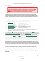
Specifically, this reply testimony addresses the following Phase 1 issues:1
1. Must a generating facility be sized no greater than its associated premises’ annual
7
load to receive CSI incentives?
8
2. Can the annual estimated generation for purposes of NEM generating facility size
9
10
requirements be calculated using the manufacturer’s inverter efficiency rate for
11
situations involving high panel to inverter ratios?
3. Can a load justification be required for a proposed NEM generating facility if the
12
system is smaller than 5 kW?
13
4. If Davis installs solar panels at properties he rents to tenants, resulting in electricity
14
15
used not by Davis but by his tenants, does the installation still “offset customer’s own
16
electrical requirements” such that the project can qualify for NEM under §
17
2827(b)(4)?
18
5. If Davis installs a solar PV system at his home and allows non-residents to use the
19
electricity generated by this PV system, does that use count as part of “customer’s
20
own electrical requirements” for purposes of NEM eligibility?
1
6HHScoping Ruling, at pp. 12-13; July 1, 2014 ALJ Email Ruling (“Parties are instructed to include
evidence related to [Issue Nos. 1, 2 and 3] in their written testimony. . . In their testimony, parties
should clearly explain the facts of the case necessary to support the arguments they intend to make in
their briefs. . . . Parties are not required to file additional legal briefs on the 3 legal issues, but parties
may elect to address the legal issues again in briefs filed after the evidentiary hearing”).
-1-
1
6. Are any safety considerations raised by determination of whether a proposed solar PV
2
system qualifies under NEM, CSI, or NSC? Are there any other safety considerations
3
raised by these consolidated proceedings?
-2-
1
,,
2
$*(1(5$7,1*)$&,/,7<&$1127%(6,=('*5($7(57+$1,76
3
$662&,$7('35(0,6(6
$118$//2$'725(&(,9(&6,,1&(17,9(6
4
Through 2006, the California Public Utilities Commission’s (the “CPUC” or the
5
“Commission”) Self-Generation Incentive Program (“SGIP”) provided incentive payments to
6
customers who installed distributed generation systems, including solar facilities. In Rulemaking
7
(R.)04-03-017, the Commission stated its intent to fund a new distributed generation program
8
specific to solar, namely the California Solar Initiative (“CSI”), and, in Decision (D.)06-01-024,
9
the Commission committed $2.5 billion to CSI over 10 years.
10
The CSI program is overseen by the CPUC and administered by investor owned utilities.
11
SCE has been a Program Administrator for the CSI program since the beginning of the program
12
in 2007. SCE is responsible for processing applications, and understands applications must be
13
processed in accordance with the requirements set forth in the relevant statutes, CPUC decisions,
14
and the CSI Handbook. SCE is also obligated to administer the CSI program in a fair, non-
15
discriminatory manner.
16
Under Section 25782 of the California Public Resources Code, a solar energy system
17
must be “intended primarily to offset part of or all of the consumer’s own electricity demand” to
18
be eligible for CSI incentives.
19
20
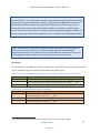
Since the inception of the CSI program, the Commission has addressed system sizing
multiple times. Section 2.2.4 of the CSI Program Handbook states:
21
22
23
24
25
26
To be eligible for CSI Incentives, the system must be sized so that the amount of
electricity produced by the system primarily offsets part or all of the Host Customer’s
electrical needs at the Project Site. Unless additional load substantiation
documentation is submitted, the estimated annual kWh production of the proposed
system as shown on the EPBB calculator may not be higher than the previous 12month energy usage.
27
Additionally, section 2.2.5 of the CSI Program Handbook states:
28
29
In accordance with Senate Bill 1 (2006), no solar energy systems that exceed a
customer’s onsite load will receive a CSI incentive.
-3-
1
SCE understands that the CSI Program Handbook is consistent with Commission
2
Decision 06-07-028, where the Commission expressly held that “the maximum solar system size
3
eligible for incentives under the … California Solar Initiative (CSI) … [is] 100% of historical
4
annual usage, based on customer usage data from the previous 12 months.” (D.06-07-028, at
5
Ordering Paragraph No. 1; VHHDOVRLG. at Conclusions of Law Paragraph No. 2 (“System size
6
eligibility requirements for solar facilities should be modified from 100% of peak load to 100%
7
of annual historical usage, based on the previous 12 months customer usage.”).
8
9
SCE has applied the system sizing requirement using the methodology described above to
approximately 57,000 applications, including Mr. Davis’s applications.
-4-
1
,,,
2
$118$/(67,0$7('*(1(5$7,210867%(&$/&8/$7('86,1*
3
67$1'$5',=(',19(57(5()),&,(1&<5$7(638%/,6+('%<7+(&(&
4
$
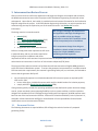
6&(+DV3URSHUO\$SSOLHG,WV1(0(VWLPDWLRQ)RUPXODV
A photovoltaic generating facility includes, among other key components, an array of
5
6
solar panels and an inverter.2 The solar panels convert solar energy into to Direct Current
7
(“DC”) electrical energy. The inverter converts the DC electrical energy to Alternating Current
8
(“AC”) electrical energy, which can then be exported to SCE’s AC electrical energy distribution
9
system.3 During the course of converting DC power to AC power, some power is lost. For
10
example, in this conversion some energy is lost to heat and some energy is lost because it is used
11
to power the inverter. An inverter’s efficiency reflects how much DC power is actually
12
converted to AC power, taking into account these losses.
To be eligible for SCE’s NEM tariff, a customer’s Renewable Electrical Generating
13
14
Facility must be “intended primarily to offset part or all of the Customer’s own electrical
15
requirements.”4 In order to determine whether a proposed facility offsets the Customer’s
16
electrical requirements, the estimated generation of the proposed facility must be calculated. To
17
do so, SCE must evaluate certain features of the proposed facility, including the number of solar
18
panels, the model of the solar panels, and the model of the inverter. SCE utilizes one of two
19
formulas to calculate the estimated monthly kilowatt-hour (“kWh”) output. Both formulas
20
applied by SCE rely upon, among other variables, an “Inverter Efficiency %” variable, which
21
reflects the anticipated DC-to-AC losses of the particular model of inverter chosen by the
22
applicant. For California Energy Commission (CEC) certified inverters—such as the inverters
2
Other key components include, among others, cables, disconnects, and connectors.
3
The amount of export to SCE would depend on the specifics of the situation, taking into account any
load “behind the meter” on an NEM type service.
4
SCE’s Tariff Schedule NEM at Sheet 13.
-5-
1
serving Mr. Davis’s currently interconnected generating facilities—SCE determines the “Inverter
2
Efficiency %” variable based upon manufacturer data published by the CEC.
The opening testimonies of David Davis and Daniel Davis request that the Commission
3
4
prospectively adopt a new formula for estimating the future kWh generation of a photovoltaic
5
generating facility.
6
1(0+DQGERRN)RUPXODV
7
To determine whether a customer’s Renewable Electrical Generating Facility is “intended
8
primarily to offset part or all of the Customer’s own electrical requirements,” SCE understands
9
that the estimated future generation of the proposed generating facility should be determined.5
10
SCE’s NEM Interconnection Handbook (“NEM Handbook”) “specifies the typical
11
minimum technical requirements to interconnect generating facilities with SCE’s electric system
12
under the Net Energy Metering (NEM) program” to process NEM applications.6 Under the
13
procedures established in the NEM Handbook, estimated monthly kWh output is calculated by
14
using either one of two formulas:7
15
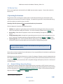
a. Formula No. 1: (CEC-AC Nameplate) x 720 x 0.2 = ____ kWh; or
16
b. Formula No. 2: The CSI EPBB calculator located at www.csi-epbb.com.
17
Both of these formulas, in turn, rely, in part, on an inverter efficiency variable.
5
SCE does not address analysis relating to the actual or reasonably anticipated annual load calculation
in this testimony because it is beyond the scope of the Phase 1 issues. In addition, SCE acknowledges
that, pursuant to the Scoping Ruling, “the scope of Phase 1 of these consolidated proceedings will not
address whether “electrical requirements” under Section 2827(b)(4) should be interpreted to limit size
based on customer peak demand or annual load.”
6
6HH NEM Handbook, Version 5.0 at p. 5. Please see Section IV for additional testimony relating to
the NEM Handbook. The NEM Handbook is also attached to this testimony as Appendix B.
7
6HHNEM Handbook, Version 5.0 at p. 7.
-6-
a)
1
Formula No. 1
For Formula No. 1, (CEC-AC Nameplate) x 720 x 0.2 = ____ kWh, SCE must calculate
2
3
the CEC-AC Nameplate.8 The CEC-AC Nameplate represents the anticipated amount of AC
4
power that the proposed generating facility can contribute to the distribution system when taking
5
into account the number of solar panels, the particular model of solar panel and the particular
6
model of inverter. Under the NEM Handbook, variable “(CEC-AC Nameplate)” is determined
7
pursuant to the following calculation:
8
(Quantity of Modules) x (PTC Rating) x (Inverter Efficiency %) / 1000 = ____ kW
9
10
11
The “Quantity of Modules” refers to the proposed generating facility’s number of PV solar
12
panels. “PTC Rating” represents the estimated power output in Watts for a particular model of
13
solar panel under specific test conditions.9 It is a standardized estimate calculated by the CEC
14
using laboratory-tested parameter values.10
The “Inverter Efficiency %” reflects anticipated power losses that occur when an inverter
15
16
converts DC to AC. During the course of converting DC power to AC power, some power is lost
17
due to heat and other factors. An inverter’s efficiency reflects how much DC power is actually
18
converted to AC power. Section 2.2 of the NEM Handbook states that for CEC-certified
8
720 represents the number of hours in a month. .2 represents the average number of full sun hours in
a 24 hour period in Southern California. SCE notes that Pacific Gas and Electric Company
(“PG&E”) uses a similar formula: (CEC-AC rating) x 8,760 hrs/yr x .19 = ___ kWh. 6HH
AGREEMENT AND CUSTOMER AUTHORIZATION, Net Energy Metering Interconnection For
Solar And/Or Wind Electric Generating Facilities Of 30 Kilowatts Or Less (Form 79-1151A, Advice
4369-E). PG&E’s formula calculates the number of hours in a year, as opposed to the number of
hours in a month.
9
“PTC” is an acronym for PVUSA Test Conditions. This is a standardized set of testing conditions
that are used to evaluate the performance of a particular model of solar panel.
10
This published data can be found at the “Go Solar California!” website, at
http://www.gosolarcalifornia.ca.gov/equipment/pv_modules.php (last visited August 1, 2014). The
modules are also required to have an ANSI/UL1703 safety certification issued by a Nationally
Recognized Testing Laboratory (NRTL).
-7-
1
equipment, an applicant must list inverter technical information consistent with the test data
2
maintained and published by the CEC. This CEC data reflects a weighted average of the inverter
3
efficiency for a particular model of inverter. This weighted average reflects a particular model’s
4
performance during different standardized measurements tested by a Nationally Recognized
5
Testing Laboratory (NRTL). Such measurements include testing at different: input voltage,
6
input current, input power, output voltage, output power, ambient temperature and inverter
7
temperature at heat sink.11 The published CEC data identifies a specific “Inverter Efficiency %”
8
for each model of inverter that is approved by the CEC.12
b)
9
Formula No. 2
For Formula No. 2, the CSI EPBB calculator, estimated generation is determined by
10
11
multiplying the “CEC-AC System Rating” by the “Design Factor.” The “CEC-AC System
12
Rating” variable is the same as the “(CEC-AC Nameplate)”:
13
(Quantity of Modules) x (PTC Rating) x (Inverter Efficiency %) / 1000 = ____ kW|
14
15
16
This variable is calculated using the same methodology discussed above. As above, SCE relies
17
on CEC data to determine the inverter efficiency % variable.
The “Design Factor” determines the estimated performance of a proposed system, when
18
19
taking into account the proposed physical location and the specific configuration of the
20
generating facility. The “Design Factor” is calculated by the National Renewable Energy
21
Laboratory’s (“NREL”)13 PV Watts version 2 (“PV Watts”) software program, which is run after
11
6HHPerformance Test Protocol for Evaluating Inverters Used in Grid-Connected Photovoltaic
Systems, Section 5.4.1 at p. 14, DYDLODEOHDW
http://www.gosolarcalifornia.ca.gov/equipment/inverters.php (last visited Aug. 1, 2014)
12
This published data can be found at http://www.gosolarcalifornia.ca.gov/equipment/inverters.php
(last visited Aug. 1, 2014).
13
NREL is a national laboratory of the U.S. Department of Energy, Office of Energy Efficiency and
Renewable Energy, operated by the Alliance for Sustainable Energy, LLC.
-8-
1
a user inputs data specific to the proposed system and proposed location (HJ: zip code; model of
2
solar panel; number of solar panels; tilt of the solar panels; azimuth of the solar panels; etc.).
Thus, as described in this section, SCE’s NEM Handbook establishes that two formulas
3
4
can be used to determine estimated kWh generation of a proposed photovoltaic generating
5
facility. Both provide a uniform, nondiscriminatory way to efficiently process thousands of
6
NEM applications.
7
8
Mr. Davis’s Second Amended Complaint requests that the Commission provide the
9
0U'DYLV¶V&XUUHQWO\,QWHUFRQQHFWHG*HQHUDWLQJ)DFLOLWLHV
following:
x
10
“with respect to 61736 Onaga, allow me NEM interconnection for an additional 30
11
horizontal panels on each of the two existing, already interconnected non-CSI 6kW
12
inverters and an additional 30 horizontal and 30 vertical panels on the existing 6kW
13
CSI inverter . . . additionally, to the extent that any estimate of anticipated production
14
might be required, that that estimate be adjusted for reduced inverter efficiency
15
caused by the high panel to inverter ratio (total three 6kw inverters with 60 horizontal
16
panels each and an additional 30 vertical panels on one);
x
17
with respect to 65911 29 Palms Hwy apartments 1-8, allow me NEM interconnection
18
for an additional 30 panels on each of the existing, 5kW, already interconnected CSI
19
inverters . . . additionally, to the extent that any estimate of anticipated production
20
might be required, that that estimate be adjusted for reduced inverter efficiency
21
caused by the high panel to inverter ratio (total 1 5kW inverter with 60 panels per
22
apartment);14
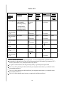
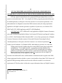
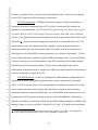
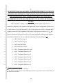
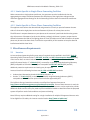
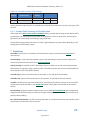
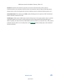
Each of the interconnected generating facilities at the nine referenced locations is
23
24
currently producing sufficient electricity to offset the load of the location:
14
Second Amended Complaint, at pp. 41-42.
-9-
Table III-1
/RFDWLRQRI
*HQHUDWLQJ
)DFLOLW\
61736 Onaga Trail
65911
TwentyNine Palms
Hwy #5
3HUPLVVLRQWR2SHUDWH
372'DWH
3UHYLRXV
5HOHYDQW
3HULRG
3UHYLRXV
5HOHYDQW
3HULRG1HW
(QHUJ\
8VDJH
N:K
&XUUHQW
5HOHYDQW3HULRG
&XUUHQW
5HOHYDQW
3HULRG1HW
(QHUJ\
8VDJH
N:K
a.12282011(for
5.996kWNEM
GeneratingFacility)
b.04/18/2013(for
expanded17.3kW
GeneratingFacility)
08282012
12242012
to1223
2013
1413
12232013to
07252014
7584
08282012
to
09182013
08282012
to
09182013
05202013
to
05192014
08012013
to
7222014
08012013
to
7222014
n/a19
9599
7601
4785
09182013
to
07222014
09182013
to
07222014
05212014
to
07222014
n/a17
0
4740
n/a18
0
12112013
to
07222014
3888
65911
TwentyNine Palms
Hwy #6
08282012
65911
TwentyNine Palms
Hwy #1
05202013
65911
TwentyNine Palms
Hwy #4
08012013
65911
TwentyNine Palms
Hwy #8
08012013
65911
TwentyNine Palms
Hwy #2
12112013
7926
1345
6073
1230
15
SCE’s Schedule NEM defines Relevant Period as: “A twelve-month period, or portion thereof,
commencing on the anniversary Date of Final Interconnection of the customer’s generator to SCE’s
electric system and on every subsequent anniversary thereof.”
16
A negative number indicates that the generating facility is generating net surplus kWh.
17
The “n/a” reflects that the prior Relevant Period just completed and no data is yet available for the
current Relevant Period.
18
The “n/a” reflects that the prior Relevant Period just completed and no data is yet available for the
current Relevant Period.
19
The “n/a” reflects that this meter has not yet completed a full Relevant Period.
-10-
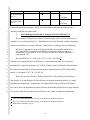
65911
TwentyNine Palms
Hwy #3
12112013
n/a20
65911
TwentyNine Palms
Hwy #7
12112013
n/a21
12112013
to
07222014
12112013
to
07222014
2732
3824
1
Each location that states negative energy usage demonstrates that the generating facility is
2
currently producing net surplus kWh.
3
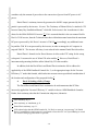
)ODZV5HODWLQJWR'DQLHO'DYLV$QDO\VLVRI,QYHUWHU(IILFLHQF\
4
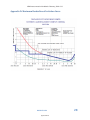
The testimony of Daniel Davis reflects a flawed critique of the “Inverter Efficiency %”
5
variable as it is used in Formula No. 1. Daniel Davis incorrectly alters this variable, changing it
6
from inverter efficiency to system efficiency. Daniel Davis’s testimony states the following:
7
8
9
10
Mr. Davis’s generators consist of 60 Schott 230 Poly solar modules which have a
PTC rating of 207.7 connected to an SB5000-US inverter which can convert a
maximum of 5.1kW from DC to AC. First we calculate the “Inverter Efficiency %”
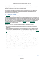
using formula (11):
11
Inverter Efficiency % = 5100 / (60 x 207.7) x 100 -= 40.924%.22
12
Daniel Davis is stating that Inverter Efficiency is calculated based upon: (1) a presumed
13
maximum AC output for an inverter (i.e. 5100 W), which is then (2) divided by the maximum
14
DC output of an attached set of solar panels (number of panels times the PTC rating of those
15
panels, i.e. 60 panels x. 207.7 W = 12,462 W).
This is not inverter efficiency. Rather, Daniel Davis is describing system efficiency.
16
17
Specifically, he is describing the system efficiency of the total generating facility for a single
18
hypothetical configuration. Assuming the AC output and DC output values used by Daniel
19
Davis are correct, the hypothetical system efficiency described by Daniel Davis is approximately
20
40.9 percent. But this is not the inverter efficiency ratio, which is a different variable that
20
The “n/a” reflects that this meter has not yet completed a full Relevant Period.
21
The “n/a” reflects that this meter has not yet completed a full Relevant Period.
22
Daniel Davis testimony, at p. 11.
-11-
1
considers only the amount of power due to the conversion of power from DC power to AC
2
power.
Daniel Davis’s testimony incorrectly presumes the full DC output generated by the 60
3
4
panels is processed by the inverter. It is not. The Testimony of Edward Soler, Jr. attached a “PV
5
Inverter Sunny Boy Installation Manual,” which Mr. Soler asserts is the “manufacturer’s data
6
sheets for the SMA SB5000-US inverter.”23 If it is assumed that this is the user manual for Mr.
7
Davis’s 5 kW inverter, then the Technical Data sheet within that manual states that the maximum
8
DC power processed by Mr. Davis’s inverter is 5300 W.24 Accordingly, any additional watts
9
beyond the 5300 W is not processed by the inverter, in order to manage the AC output to its
10
targeted 5000 W. The inverter efficiency is not reduced in the manner Daniel Davis describes.
11
Daniel Davis’s formula is also flawed because it relies on the PTC rating for the wrong
12
solar panel. It assumes the use of Schott 230 solar modules.25 However, David Davis’s
13
interconnected generating facilities utilize Schott Poly 225 solar modules.
In addition, both the David Davis and Daniel Davis testimonies fail to address the
14
15
applicability of the NEM Handbook Formula No. 2, or the appropriate input for the “Inverter
16
Efficiency %” under that formula, which takes into account a more specialized consideration of
17
the location and configuration of the proposed facility.26
18
'DYLV,V6HHNLQJD3ROLF\&KDQJH
19
The David Davis and Daniel Davis testimonies do not demonstrate that SCE has
20
incorrectly applied the “Inverter Efficiency %” variable in the two NEM Handbook formulas.
21
Rather, their testimony asks that the Commission adopt new, alternative
23
Soler testimony, at p. 1.
24
Soler testimony, at Attachment, p. 91.
25
Daniel Davis testimony, at p. 11.
26
SCE acknowledges that the NEM Formula No. 2 is likely to return an “error message” for Daniel
Davis’s hypothetical system because it is configured to cause the CEC-AC System Rating to exceed
the inverter’s rating by greater than 125 percent.
-12-
1
formulas/methodologies. Both David Davis and Daniel Davis propose to use the inverter
2
manufacturer’s (SMA America) Sunny Design tool. This Sunny Design tool is web-based
3
software published on the inverter manufacturer’s website. SCE believes it is inappropriate to
4
rely upon individual inverter manufacturer software. SCE relies upon standardized formulas,
5
using inputs set by the CEC that can be used to efficiently process thousands of NEM
6
applications in a uniform and nondiscriminatory way.
Daniel Davis also proposes to use the NREL System Advisor Model (SAM).27 While the
7
8
NREL SAM may be a reasonable methodology to use to estimate generation, in developing
9
policies and procedures for processing NEM applications, SCE elected to use the above
10
described two NEM Handbook Formulas. These formulas are published in the NEM Handbook,
11
which has been used to process thousands of NEM interconnections since 2011, as discussed in
12
Section IV of this testimony. Daniel Davis is asking to permit Mr. Davis to rely upon an
13
alternative methodology that is different from the standard processes that SCE has applied to
14
thousands of other NEM applicants.
Mr. Davis’s hypothetical system configuration (i.e. 60 solar panels per 5 kW or 6 kW
15
16
inverter) is unusual. The vast majority of applications processed by SCE do not contain this type
17
of high panel-to-inverter ratio. In fact, the NEM Formula No. 2 (i.e. the CSI EPBB calculator),
18
would return an “error message” for the hypothetical system proposed by Mr. Davis.28 Although
19
the NEM Formula No. 1 does not have a built-in “error message” that prevents calculation of
20
such overloading, it is not designed to address such substantial overloading beyond the rating of
21
an inverter.
27
Daniel Davis testimony, at p. 14.
28
The CSI Calculator User Guide version 5 (“CSI Calculator User Guide”), which outlines NEM
Handbook Formula No. 2 states: “if the CEC-AC rating of the proposed system is greater than 125
percent of the inverter rating, an error is flagged which must be corrected (by reducing the number of
panels, choosing a lower PTC rated panel, increasing the number of inverters or choosing a larger
capacity inverter) before being allowed to proceed to the results page.” 6HHCSI Calculator User
Guide, at p. 5, DYDLODEOHDWhttp://www.csi-epbb.com/CSICalculatorV4UserGuide.pdf
-13-
1
Indeed, according to Mr. Davis himself, his hypothetical system is extremely inefficient.
2
Even assuming his testimony is correct, Mr. Davis concedes that the overall efficiency of the
3
system he proposes would only output 40.9 percent of the DC power produced by the solar
4
panels. If Mr. Davis did not “overload” the inverters with such a large number of panels, the
5
proposed facility would not waste as much energy. However, Mr. Davis’s proposed
6
“overloading” of the Sunny Boy inverters located at the properties described in Section IV.A.2
7
remains hypothetical.
-14-
1
,9
2
6&(0$<5(48,5(/2$'-867,),&$7,21)25$352326('1(0
3
*(1(5$7,1*)$&,/,7<(9(1,)7+(6<67(0,66,=('60$//(57+$1.:
SCE may require load justification for a proposed NEM generating facility even if the
4
5
system is sized smaller than 5 kW. To be eligible for NEM, a proposed generation facility must
6
be intended primarily to offset part of all of the customer’s own electrical requirements. SCE
7
understands that it is obligated to ensure that NEM customers satisfy the sizing requirements
8
applicable to all eligible customer-generators, regardless of system size, as set forth in SCE’s
9
NEM Tariff, SCE’s NEM Application, and SCE’s NEM Handbook.
10
SCE NEM Tariff. SCE’s NEM tariff is only applicable to Eligible Customer-Generators,
11
as the term is defined in both Public Utilities Code Section 2827(b)(4)(A) and Special Condition
12
6.a of SCE’s Tariff Schedule NEM (“Schedule NEM”). One of the requirements for DOOEligible
13
Customer-Generators is that the customer’s Renewable Electrical Generating Facility be
14
“intended primarily to offset part or all of the Customer’s own electrical requirements.”29
15
Further, Special Condition 6.f of Schedule NEM, which addresses generator size, states that:
Nothing in this Special Condition alters the existing NEM system sizing requirements
and limitations. To be eligible for NSC, a system must meet the definition of an
eligible customer-generator within Section 2827(b)(4), including that it be intended
primarily to offset part or all of the customer’s own electrical requirements. Systems
that are sized larger than the customer’s electrical requirements are not eligible for
NEM and therefore, are not eligible for NSC.”30
16
17
18
19
20
21
22
Nowhere in the NEM tariff is there a differentiation or distinction made in regards to the NEM
23
sizing requirements based on whether a system is sized smaller or larger than 5 kW. Because DOO
24
proposed NEM generating facilities must be sized to offset the customer’s own electrical
25
requirements, SCE believes that it is allowed to request information from DQ\ Eligible Customer-
29
SCE’s Tariff Schedule NEM at Sheet 13.
30
,G at Sheet 14.
-15-
1
Generator, regardless of the size of the proposed generating facility, to help ensure compliance
2
with its CPUC-approved tariffs and statutory requirements.
SCE NEM Application. All Eligible Customer-Generators seeking to interconnect a
3
4
Renewable Electrical Generating facility to SCE’s electric system must first complete an
5
application for interconnection. SCE’s Form 14-753, $SSOLFDWLRQIRU1HW(QHUJ\0HWHULQJRID
6
1HZ6RODU:LQGRU)XHO&HOO*HQHUDWLQJ)DFLOLW\RI1RW0RUH7KDQN:8QGHU1(05DWH
7
6FKHGXOH, is the applicable interconnection application for most generating facilities sized 10 kW
8
and smaller31 – which necessarily encompasses systems that are sized smaller than 5 kW. The
9
Applicability section of this application informs Eligible Customer-Generators that their
10
generating facilities must operate in parallel with SCE’s electric system “for the purpose of
11
offsetting part or all of the eligible customer-generator’s own electrical requirements.” The last
12
section of this application, captioned “Qualified NEM Generating Facility,” requires all Eligible
13
Customer-Generators to provide information so that SCE can calculate the estimated monthly
14
kWh production of the generating facility. Nowhere in the NEM Application is there a
15
differentiation or distinction made in regards to the NEM sizing requirements based on whether a
16
system is sized smaller or larger than 5 kW.
SCE NEM Handbook. Further, SCE publishes the NEM Handbook (included herein as
17
18
Appendix B) to specify the minimum requirements necessary to interconnect a generating
19
facility to SCE’s electrical system. SCE first published the Handbook in October 2011 to help
20
answer technical questions from customers and contractors in regards to interconnecting
21
generating facilities pursuant to the NEM tariff. Over 60,000 NEM interconnections have been
22
completed since SCE first began referring customers to the NEM Handbook. Although not
23
officially filed with the Commission, SCE makes the NEM Handbook publically available on the
24
internet, at https://www.sce.com/NR/sc3/tm2/pdf/ce158-12.pdf. SCE applies the requirements
31
Generating facilities that include paired energy storage systems, for example, must complete the
longer interconnection application, Form 14-732, regardless of system size.
-16-
1
of the NEM Handbook to all NEM Eligible Customer-Generators to help ensure fair, non-
2
discriminatory and equal access to the NEM program.
Tables 2.2-2 and 2.2-4 of the NEM Handbook outline the standard formulas used to
3
4
calculate the CEC-AC nameplate system size (kW) and estimated monthly kWh output for solar
5
PV generating facilities applying under the NEM program.32 This information is used by SCE to
6
help ensure that the proposed generating facility is sized to offset the customer’s own electrical
7
requirements. Nowhere in the NEM Handbook is there a differentiation or distinction made in
8
regards to the NEM sizing requirements based on whether a system is sized smaller or larger
9
than 5 kW.
10
Because all Eligible Customer-Generators must comply with the requirement that their
11
proposed generating facilities be sized to offset part or all of their own electrical requirements,
12
SCE understands that it may request load justification from any Eligible Customer-Generator to
13
help ensure compliance with this requirement, regardless of the size of the proposed generating
14
facility.
32
NEM Handbook, Version 5.0 at p. 7.
-17-
1
9
2
,)'$9,6,167$//662/$53$1(/6$73523(57,(6+(5(176727(1$176
3
5(68/7,1*,1(/(&75,&,7<86('127%<'$9,6%87%<+,67(1$1767+(
4
,167$//$7,210$<67,//2))6(7&86720(5
62:1(/(&75,&$/
5
5(48,5(0(17668&+7+$77+(352-(&7&$148$/,)<)251(081'(5
6
%
7
SCE’s Tariff Rule 1 defines “Customer” as “the person in whose name service is
8
rendered as evidenced by the signature on the application, contract or agreement for that service,
9
or, in the absence of a signed instrument, by the receipt and payment of bills or Summary Bills
10
regularly issued in his name regardless of the identity of the actual user of the service.”33 Mr.
11
Davis is the customer of record for the Service Accounts associated with each of the locations
12
identified in the March 24, 2014 revised Joint Prehearing Conference Statement: 34
13
x
60215 Alta Loma Apt. A
14
x
60215 Alta Loma Apt. B
15
x
60219 Alta Loma Apt A
16
x
60219 Alta Loma, Apt B
17
x
65911 Twentynine Palms Hwy Apt 1
18
x
65911 Twentynine Palms Hwy #2
19
x
65911 Twentynine Palms Hwy #3
20
x
65911 Twentynine Palms Hwy #4
21
x
65911 Twentynine Palms Hwy #5
22
x
65911 Twentynine Palms Hwy #6
23
x
65911 Twentynine Palms Hwy #7
33
SCE’s Tariff Rule 1, 'HILQLWLRQV, at Sheet 3.
34
Mr. Davis is also the customer on the NEM Interconnection Agreements for these locations that were
entered into with SCE.
-18-
1
x
65911 TwentyNine Palms Hwy #8
2
x
6804 Park Blvd
3
x
6804 Park Blvd #1
4
x
6804 Park Blvd #2
5
x
6804 Park Blvd #3
6
x
6804 Park Blvd #4
7
x
6807 Park Blvd.
8
x
6815 Park Blvd
9
x
61736 Onaga Trail
10
Pursuant to Rule 1, regardless of the actual user of the service, the load registered on the
11
applicable meters is considered Mr. Davis’s responsibility since service is rendered in his name.
12
Therefore, SCE believes that it appropriately allowed Mr. Davis to use the load registered on the
13
meters that are in his name, for which he is financially responsible, as his own electrical
14
requirements for the purposes of participating in the NEM program, which is consistent with
15
how SCE applies these requirements to its other customers.35
SCE’s Tariff Rule 18, 6XSSO\WR6HSDUDWH3UHPLVHVDQG8VH%\2WKHUV, governs how Mr.
16
17
Davis is to charge his tenants for the electricity that is registered on meters that are in his name.
18
Specifically, Rule 18, Section E.2 states, in part, that “A customer shall not charge for electricity
19
received from SCE and used by another person, except:...Where the charge to GRPHVWLF or
20
nondomestic WHQDQWV is absorbed in the rental for the Premises or space occupied, is not
21
separately identified, and does not vary with electrical usage…” (Emphasis added).36 All
22
customers to whom this requirement is applicable, including Mr. Davis, are required under
23
SCE’s tariffs to comply with this provision.
35
Mr. Davis also entered into the NEM Interconnection Agreement with SCE for the Renewable
Electrical Generating Facilities associated with these accounts, and is therefore considered the NEM
Eligible Customer-Generator for these accounts.
36
SCE’s Tariff Rule 18, 6XSSO\WR6HSDUDWH3UHPLVHVDQG8VH%\2WKHUV, at Sheet 1.
-19-
However, this assumes that the load registered on the meters to which the Renewable
1
2
Electrical Generating Facilities are interconnected meet the applicability requirements for the
3
rate under which those services are billed. The accounts listed above are all served under SCE’s
4
Schedule D – Domestic Service. Schedule D is applicable to “domestic service including
5
lighting, heating, cooking, and power or combination thereof in a Single-Family Accommodation
6
or an individually metered Single-Family Dwelling in a Multifamily Accommodation.” Based
7
on SCE’s understanding of the characteristics of the accounts listed above, the usage on those
8
meters meet the applicability requirements for receiving Domestic Service and are appropriately
9
served under Schedule D.37 Schedule NEM can then be applied as a rider to the accounts’
10
otherwise applicable rate schedules (i.e., Schedule D), and the load registered on those accounts
11
is appropriately considered the customer of record’s (i.e., Mr. Davis) own electrical requirements
12
for the purposes of participating in NEM.
37
SCE notes that Schedule D does not contain Demand Charges. Under Schedule D, customers are
responsible for $/kWh energy charges based on a tiered rate structure and a Basic or Minimum
Charge. For instance, the Basic Charge for a Multifamily Accommodation is $0.024/meter/day (or
$0.72/meter/month based on a 30-day billing period).
-20-
1
9,
2
,)'$9,6,167$//6$62/$5396<67(0$7+,6+20($1'$//2:6121
3
5(6,'(1767286(7+((/(&75,&,7<*(1(5$7('%<7+,6396<67(0
4
7+$786(0$<&2817$63$572)&86720(5
62:1(/(&75,&$/
5
5(48,5(0(176)25385326(62)1(0(/,*,%,/,7<
For the purpose of this response, SCE answers assuming that Mr. Davis intends to allow
6
7
non-residential third-party electric vehicle (EV) charging usage to register on his home’s
8
Domestic Service meter, to which a Renewable Electrical Generating Facility would be installed
9
under Schedule NEM to help offset the costs of EV charging.38
As a threshold matter, Mr. Davis can power his EV charger in a variety of ways. For
10
11
example, he can supply power to it from an isolated generating facility (i.e., neither the
12
generating facility nor the fast charger will operate in parallel with SCE’s distribution system).
13
Alternatively, Mr. Davis can elect to utilize the fast charger by receiving service from SCE’s
14
distribution system under an appropriate electric vehicle tariff.
If Mr. Davis elects to receive service from SCE’s distribution system, he can then elect to
15
16
offset that electric vehicle load via a generating facility in one of two ways. First, he can supply
17
power to the EV charger from an isolated generating facility, and install an Automatic Transfer
18
Switch that would allow him to power his EV charger with electricity from the grid when his
19
generating facility is unavailable for use. Alternatively, he could also apply to interconnect that
20
generating facility to SCE’s distribution system.
If Mr. Davis interconnects his proposed facility to SCE’s distribution system, he can then
21
22
enroll in the NEM program provided his interconnection meets all requirements of the NEM
23
tariff. As outlined in the response to Question VI above, SCE understands that any load that
38
Mr. Davis has submitted one Rule 21 Application to install a 95 kW solar generating facility at 61736
Onaga, Joshua Tree, CA 92252, which Complainant represented was intended to serve an electric
vehicle charger. SCE has no record regarding any additional applications for interconnection of
NEM-eligible generating facilities by Mr. Davis to serve load of other, unspecified EVchargers.
-21-
1
registers on a specific meter is considered the responsibility of the customer in whose name
2
service is rendered, regardless of the actual user of the electricity. For NEM purposes, SCE
3
considers any load that registers on the meter to which the Renewable Electrical Generating
4
Facility is interconnected to be the “customer’s own electrical requirements.” Because Mr.
5
Davis is the customer of record for the Service Account associated with the meter located at his
6
residence at 62736 Onaga, SCE would consider the load registered on Mr. Davis’s meter as Mr.
7
Davis’s “own electrical requirements,” regardless of whether he allows non-residents to use the
8
electricity generated by his facility.
But this assumes that the registered load meets the applicability requirements for the
9
10
otherwise applicable rate schedule (e.g., Schedule D) under which service is rendered. Schedule
11
NEM is not a standalone tariff. SCE applies Schedule NEM as a rider tariff to the customer’s
12
otherwise applicable rate schedule to allow for the monthly netting of energy consumed with
13
energy exported to the grid over a 12-month Relevant Period.39 Schedule NEM does not alter
14
the underlying applicability requirements for the otherwise applicable rate schedule under which
15
a customer is appropriately served.
16
Mr. Davis has represented to SCE that he desires to oversize his NEM generating
17
facility(ies) to avoid paying Demand Charges that may be caused by the installation and use of a
18
50 kW EV fast charger.40 However, Mr. Davis would only be responsible for Demand Charges
19
to the extent that his EV charging load must be served on an otherwise applicable rate schedule
20
that contains Demand Charges. Currently, EV fast chargers that are both (a) installed at
21
residential Single-Family Accommodation locations and (b) used for residential purposes, are
39
Schedule NEM does not allow for the netting of demand (kW) charges; only energy (kWh) charges
and credits are netted. A customer that installs a generating facility may see a reduction in Demand
Charges because of the coincidence of the electricity generated by the generating facility and the
customer’s peak demand load but that is a function of installing a generating facility; it is not a
function of being served on Schedule NEM since NEM does not net Demand Charges.
40
6HHHJ, Complaint (C.12-08-015), at p. 3.
-22-
1
eligible for SCE’s Domestic Service EV tariffs, including Schedules TOU-D-TEV and TOU-EV-
2
1. These Domestic Service EV tariffs do not contain Demand Charges.
If Mr. Davis chooses to make the EV fast charger available to non-residential third
3
4
parties, then SCE understands that it must separately meter that load from the Domestic Service
5
load and serve the non-residential load on the applicable General Service rate schedule, such as
6
TOU-GS-2 or TOU-EV-4. 41 Both of these General Service rate schedules contain Demand
7
Charges, and these Demand Charges are applicable to all customers who are appropriately served
8
on these rate schedules.
In sum, for NEM purposes, SCE considers the usage served on the Domestic Service
9
10
meter to be Mr. Davis’s “own electrical requirements” for the NEM generating facility
11
interconnected to the Domestic Service meter. Any non-residential EV charging load
12
appropriately served on the applicable General Service rate schedule would also be considered
13
Mr. Davis’s “own electrical requirements” for the NEM generating facility interconnected to the
41
This requirement is found in SCE’s Tariff Rule 1, 'HILQLWLRQV, which defines “Domestic Service” as
follows: “Service for residential use at a Single-Family Dwelling premises. Any service for other
than residential use at a Single-Family Dwelling premises may be served through the domestic
service meter RQO\ZKHUHVXFKQRQGRPHVWLFFRQQHFWHGORDGGRHVQRWH[FHHGZDWWVIRUOLJKWLQJ
RUKSIRUSRZHU´(emphasis added).
-23-
1
General Service meter.42 But non-residential EV charging load registered on a Domestic Service
2
meter would be out of compliance with SCE’s rate schedules.43
42
Effective July 21, 2014, SCE’s NEM tariff now allows Eligible Customer-Generators with additional
metered service accounts located on the property where the Renewable Electrical Generating Facility
is located, and/or on property adjacent or contiguous to that property, if those properties are all solely
owned, leased or rented by the same Eligible Customer-Generator, to have the load of all the meters
aggregated for the purposes of participating in NEM (referred to as “NEM Aggregation”). This
means that Mr. Davis could install one Renewable Electrical Generating Facility on either the
Domestic Service meter or the General Service meter (assuming he qualifies for this additional meter)
that is sized to offset the electrical requirements of the aggregated load from both meters. The load
from both meters is considered the customer’s own electrical requirements for the purposes of
participating in NEM Aggregation.
43
6HH SCE’s Tariff Rule 11, Section G, 1RQFRPSOLDQFH: “Except as otherwise specifically provided in
this Rule 11, where SCE determines that a customer is in noncompliance with any tariff schedule,
SCE at its option may…(1) Transfer the customer to another tariff for which the customer can
qualify; or (2) Withhold payment of any credits or discounts applicable to the customer’s existing
tariff schedule; or (3) Discontinue service to the customer.”
-24-
1
9,,
2
27+(56$)(7<&216,'(5$7,2165$,6('%<7+(6(&2162/,'$7('
3
352&((',1*6
4
Safety and reliability considerations are raised every time an interconnection applicant
5
submits a request to interconnect a new generating facility, or to increase the capacity of, or
6
make a material modification to the operating characteristics of, an existing generating facility
7
that is interconnected with SCE’s Distribution or Transmission system. These safety and
8
reliability concerns must be evaluated on a case-by-case basis. SCE notes that the hypothetical
9
system configurations referenced by Mr. Davis on pages 41 and 42 of the Second Amended
10
Complaint have not been submitted to SCE in an appropriate application and thus SCE has not
11
reviewed the system configurations for safety and reliability.
-25-
$SSHQGL[$
:LWQHVV4XDOLILFDWLRQV
1
6287+(51&$/,)251,$(',621&203$1<
2
48$/,),&$7,216$1'35(3$5('7(67,021<
3
2)-(11,)(5.$03+8,6
4
Q.
Please state your name and business address for the record.
5
A.
My name is Jennifer Kamphuis, and my business address is 2244 Walnut Grove Avenue,
Rosemead, California 91770.
6
7
Q.
Briefly describe your present responsibilities at the Southern California Edison Company.
8
A.
I am the Program Manager for the Distributed Generation department in Customer
Service Organization at Southern California Edison. For the past 3 years, I have been the
9
10
Program Manager (PM) responsible for administrating the California Solar Initiative
11
(CSI) Residential and Non-Residential programs and ensuring compliance in application
12
processing. As the CSI PM, I am the subject matter expert on CSI Program rules and
13
requirements set forth by the California Public Utility Commission.
14
Q.
Briefly describe your educational and professional background.
15
A.
I have a Bachelor’s Degree in Liberal Studies for the California State University of San
16
Bernardino. I have been an employee of SCE for three years in the Manager of Programs
17
and Contracts role for Distributed Generation working directly on the CSI Program.
18
Prior to coming to SCE, I worked as an Account Manager in the wholesale mortgage
19
lending industry for 4 years. I have not previously testified before the California Public
20
Utilities Commission.
21
Q.
What is the purpose of your testimony in this proceeding?
22
A.
The purpose of my testimony in this proceeding is to sponsor portions Exhibit SCE-01, as
identified in the Table of Contents thereto.
23
24
Q.
Was this material prepared by you or under your supervision?
A-1
1
A.
Yes, it was.
2
Q.
Insofar as this material is factual in nature, do you believe it to be correct?
3
A.
Yes, I do.
4
Q.
Insofar as this material is in the nature of opinion or judgment, does it represent your best
judgment?
5
6
A.
Yes, it does.
7
Q.
Does this conclude your qualifications and prepared testimony?
8
A.
Yes, it does.
A-2
1
6287+(51&$/,)251,$(',621&203$1<
2
48$/,),&$7,216$1'35(3$5('7(67,021<
3
2)9,6+$/3$7(/
4
Q.
Please state your name and business address for the record.
5
A.
My name is Vishal Patel, and my business address is 3 Innovation Way, Pomona,
California 91768.
6
7
Q.
Briefly describe your present responsibilities at the Southern California Edison Company.
8
A.
I am currently a Senior Power Systems Planner fulfilling the role of Manager of
Generation Interconnections in the Distribution Engineering department. Distribution
9
10
Engineering is a group within the Electric System Planning (ESP) department, under the
11
Transmission and Distribution operating unit. I am responsible for overseeing a group of
12
engineers and technical specialists that perform technical studies and other related tasks
13
necessary to interconnect generation to SCE’s distribution systems via the Rule 21 and
14
WDAT (FERC jurisdictional) tariffs. Prior to this, I was a Senior Power Systems Planner
15
in various Transmission Planning organizations within ESP. I have performed
16
transmission planning studies on different portions of the SCE transmission system which
17
have evaluated system reliability, generation interconnection and inter-utility transfer
18
capability issues, in addition to sponsoring capital projects to maintain system reliability.
19
Q.
Briefly describe your educational and professional background.
20
A.
I obtained a Bachelor of Science degree in Electrical Engineering from California State
21
Polytechnic University, Pomona. Additionally, I am a Registered Professional Engineer
22
in Electrical Engineering in the State of California and a member of the Institute of
23
Electrical and Electronics Engineers (IEEE). I have worked at SCE since 2006.
24
Q.
What is the purpose of your testimony in this proceeding?
A-3
1
A.
The purpose of my testimony in this proceeding is to sponsor portions Exhibit SCE-01, as
identified in the Table of Contents thereto..
2
3
Q.
Was this material prepared by you or under your supervision?
4
A.
Yes, it was.
5
Q.
Insofar as this material is factual in nature, do you believe it to be correct?
6
A.
Yes, I do.
7
Q.
Insofar as this material is in the nature of opinion or judgment, does it represent your best
judgment?
8
9
A.
Yes, it does.
10
Q.
Does this conclude your qualifications and prepared testimony?
11
A.
Yes, it does.
A-4
1
6287+(51&$/,)251,$(',621&203$1<
2
48$/,),&$7,216$1'35(3$5('7(67,021<
3
2)(5,138/*$5
4
Q.
Please state your name and business address for the record.
5
A.
My name is Erin Pulgar, and my business address is 8631 Rush Street, Rosemead,
California 91770.
6
7
Q.
Briefly describe your present responsibilities at the Southern California Edison Company.
8
A.
I am currently a Manager of Programs and Contracts in SCE’s Regulatory Operations
9
Department. As such, I am responsible for providing tariff-related subject matter
10
expertise on existing CPUC tariffs and for implementing new statutes and CPUC
11
decisions into SCE’s CPUC tariff book. I also provide tariff expertise in the resolution of
12
informal and formal complaints with the CPUC.
13
Q.
Briefly describe your educational and professional background.
14
A.
I hold a Bachelor’s degree in Public Relations and Political Science from the University
15
of Southern California. I have over three and a half years of experience working at SCE.
16
Prior to my current position, I was a project manager in the Revenue Service
17
Organization, where I was responsible for operational compliance with SCE’s billing-
18
related tariffs. Before joining SCE, I worked six years for AeroVironment, Inc. as a
19
program manager responsible for implementing engineering projects related to electric
20
vehicle charging and other energy-related areas. I have not previously testified before the
21
California Public Utilities Commission.
22
Q.
What is the purpose of your testimony in this proceeding?
23
A.
The purpose of my testimony in this proceeding is to sponsor portions Exhibit SCE-01, as
identified in the Table of Contents thereto.
24
25
Q.
Was this material prepared by you or under your supervision?
A-5
1
A.
Yes, it was.
2
Q.
Insofar as this material is factual in nature, do you believe it to be correct?
3
A.
Yes, I do.
4
Q.
Insofar as this material is in the nature of opinion or judgment, does it represent your best
judgment?
5
6
A.
Yes, it does.
7
Q.
Does this conclude your qualifications and prepared testimony?
8
A. Yes, it does.
A-6
$SSHQGL[%
1HW(QHUJ\0HWHULQJ,QWHUFRQQHFWLRQ+DQGERRN
9HUVLRQ(IIHFWLYH'DWH)HEUXDU\
Version 5.0
Effective Date: February 2014
R-850-V5-0414
Appendix B-1
What’s New
This handbook has been updated from the previous version to reflect the following:
Section 2.2 – Provide further clarification on the applicability of the NEM tariff in reference to the 1
MW maximum system size for Eligible Customer-Generators.
Section 5.3 /Appendix F – Shift decal and picture requirement to beginning of the interconnection
application process to reduce technical review time frame.
Section 5.5 – Clarify wiring instructions for Net Generator Output Meter (NGOM)
R-850-V5-0414
Appendix B-2
NEM Interconnection Handbook: February, 2014 v 5.0
Contents
1.
Overview ............................................................................................................................................... 5
2.1
Document Requirements .............................................................................................................. 6
2.2
Reference Information .................................................................................................................. 6
Table 2.2-1: CEC Certified Equipment Listings ...................................................................................... 6
Table 2.2-2: CEC-AC Nameplate Calculation for Inverter based Generation Facilities ......................... 7
Table 2.2-4: Estimated Monthly kWh Calculation ................................................................................ 7
3.
Interconnection Review Process ........................................................................................................... 8
3.1
Document Review ......................................................................................................................... 8
3.2
Commissioning Test ...................................................................................................................... 9
3.3
Interconnection Study................................................................................................................... 9
3.4
Review Fees................................................................................................................................. 10
4 Operating Evaluations .............................................................................................................................. 10
4.1
5
Normal Voltage Operating Range ............................................................................................... 10
4.1.1
Limits Specific to Single-Phase Generating Facilities .............................................................. 11
4.1.2
Limits Specific to Three-Phase Generating Facilities .............................................................. 11
Miscellaneous Requirements .............................................................................................................. 11
5.1
Inverter ....................................................................................................................................... 11
5.2
Single Line Diagram ..................................................................................................................... 12
5.2.1
Visible Open AC Disconnect Switch requirements for generation interconnection to
distribution voltages 34.5KV or below .................................................................................................... 13
5.2.2
Disconnects must be reviewed and approved by Field Engineering. Location of AC
Disconnect........................................................................................................................................... 13
5.2.3
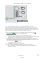
Self-Contained Meter with one main switch (CB)............................................................... 14
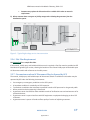
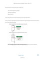
Figure 1- Typical self-contained meter system ................................................................................... 15
5.2.4
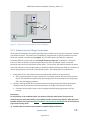
Non Self-Contained Meter – Secondary Voltage Connection............................................. 15
Figure 2 - Typical non-self-contained meter switchgear .................................................................... 16
5.2.5
Primary Service Voltage Connections ................................................................................. 16
Figure 3 - Typical high voltage service interconnection...................................................................... 17
5.2.6
Plot Plan Requirement ........................................................................................................ 17
5.2.7
Circumstances when AC Disconnect May be Opened by SCE............................................. 17
R-850-V5-0414
Appendix B-3
NEM Interconnection Handbook: February, 2014 v 5.0
5.3
Signage Requirements ................................................................................................................ 18
5.4
Telemetering ............................................................................................................................... 19
5.5
Net Generation Output Meter (NGOM) ..................................................................................... 19
5.5.1
AC Disconnect requirement for NGO meter sockets .............................................................. 19
Figure 4 - Typical self-contained meter system with NGO metering and AC Disconnects ................. 20
Figure 5-Wiring of a NGO meter socket for Virtual Net Metering projects ........................................ 20
6
5.6
Generating Systems with Battery Back-Up ................................................................................. 21
5.7
Secondary Network Interconnection .......................................................................................... 21
Protection Requirements .................................................................................................................... 21
6.1
Inverter Protection Settings ........................................................................................................ 22
Table 7.1-1 Voltage Relay Settings ...................................................................................................... 22
Table 7.1-2 Frequency Relay Trip Settings .......................................................................................... 23
6.1.1
7
Ground-Fault-Sensing and Stabilization.............................................................................. 23
Definitions ........................................................................................................................................... 23
Appendix A: Sample Single Line Diagram ................................................................................................... 25
Appendix B: Sample Plot Plan ..................................................................................................................... 26
Appendix C: Inverter Settings Request ....................................................................................................... 27
Appendix D: Maximum Borderline of Irritation Curve ................................................................................ 28
Appendix E: Supply Side / Line Side connections ....................................................................................... 29
Appendix F: Vendor Decal instructions ....................................................................................................... 31
R-850-V5-0414
Appendix B-4
NEM Interconnection Handbook: February, 2014 v 5.0
1. Overview
A generating facility may not be operated in parallel with SCE’s Distribution
facilities UNTIL PERMISSION TO OPERATE IS GRANTED BY SCE, as required in Electric
Rule 21 (PDF). Unauthorized operation may result in personal injury, equipment
damage and/or property damage for which the customer may be liable.
This NEM Interconnection Handbook specifies the typical minimum technical requirements to
interconnect generating facilities with SCE’s electric system under the Net Energy Metering (NEM)
program. These requirements are necessary to ensure safe and reliable operation of SCE’s electric
system.
These requirements apply to interconnection of a generating facility to SCE’s electrical distribution
system through the NEM program under the following SCE rate schedules:
Schedule NEM (PDF):
Net Energy Metering
Schedule FC-NEM (PDF):
Fuel Cell Net Energy Metering
Schedule NEM-V (PDF):
Virtual Net Metering
Schedule MASH-VNM (PDF): Multi-family Affordable Solar Housing
Schedule BG-NEM (PDF):
Biogas Net Energy Metering
(Note: per CPUC §2827.9, biogas digester generators must have commenced operation by
December 31, 2009 to be eligible for the program)
This handbook does not address other types of generator interconnections under Rule 21 (PDF) or the
Wholesale Distribution Access Tariff (WDAT) (PDF). Note: Schedule RES-BCT (PDF) (Renewable Energy
Self-Generation - Bill Credit Transfer) is addressed under Rule 21. For technical requirements for
interconnection under Rule 21 (PDF) or WDAT, please refer to SCE’s Interconnection Handbook (PDF).
Under the Net Energy Metering program (CPUC §2827), customers installing generating facilities are
eligible to interconnect if the generating facility is located on the customer’s premises, generates
electricity from a renewable source pursuant to paragraph (1) of subdivision (a) of Section 25742 of the
Public Resources Code (i.e., biomass, solar thermal, photovoltaic, wind, geothermal, fuel cells using
renewable fuels, small hydroelectric generation, digester gas, municipal solid waste conversion, landfill
gas, ocean wave, ocean thermal, or tidal current), fuel cells or biogas, or a hybrid of these technologies,
and is sized to offset all or part of the customer’s electrical requirements up to 1 MW.
To deliver incidental power to the grid, a customer’s generating system must be located on the
customer’s premises and be interconnected to SCE's electrical system, i.e. permanently connected to
allow “parallel operation” with the utility grid. (Note: for standby and back-up generators not
permanently connected to SCE’s electrical system, please refer to the notice requirements defined in
Section 5.8).
R-850-V5-0414
Appendix B-5
5
NEM Interconnection Handbook: February, 2014 v 5.0
2. Reference Information
Please visit http://www.sce.com/nem:
x
x
x
x
2.1
For more information about the NEM Program, NEM Rate Schedules, and review process;
To download checklists, applications, sample Single Line Diagrams and Plot Plan, and NEM
Interconnection Agreements;
Technical requirements for interconnection under Rule 21 (PDF)
To read Frequently Asked Questions and Tips to Speed through Interconnection.
Document Requirements
At http://www.sce.com/nem, SCE provides checklists, listing all the required documents for NEM
Interconnection, as well as all the required forms along with mark-ups and sample Single Line Diagram
and Plot Plan for download.
The NEM Interconnection review process is entirely paperless for solar and wind projects. NEM
Interconnection application documents should be submitted to the NEM Interconnection team via email
to [email protected] or via fax to (626) 571-4272. Note: SCE can accept email
attachments up to 7 MB; if the total size of attached files exceeds 7 MB, please submit them in multiple
emails adding the following to the subject lines: ‘part 1 of 2,’ ‘part 2 of 2,’ etc.
Signed Interconnection Agreements can be submitted digitally for Form 14-933 and 16-344. However,
originals of customer signed Agreements for Schedules FC-NEM (PDF), NEM-V (PDF), and MASH-VNM
(PDF) must be submitted via mail to:
Southern California Edison
Attention: NEM Program
P.O. Box 800
Rosemead, CA 91770
2.2
Reference Information
Certified Equipment Listings
For CEC-certified equipment, list the manufacturer, model number, rating, voltage and other required
information on the Application and Single Line Diagram exactly as shown at the following on-line
resources:
Table 2.2-1: CEC Certified Equipment Listings
Equipment
Certified Listings
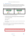
Inverters
Solar: http://www.csi-epbb.com/default.aspx
Wind, Fuel Cell: http://www.consumerenergycenter.org/erprebate/inverter.php
Solar PV Modules
http://www.csi-epbb.com/default.aspx
Wind Turbines
http://www.consumerenergycenter.org/cgi-bin/eligible_smallwind.cgi
Fuel Cells
http://www.consumerenergycenter.org/erprebate/eligibile_fuelcells.html
R-850-V5-0414
Appendix B-6
6
NEM Interconnection Handbook: February, 2014 v 5.0
NOTE: The certification listings above identify some of the electrical components on a
generating facility. These components must be incorporated in the generating electrical design
to ensure that the generating facility as whole is compliant with the NEM tariff requirements.
Solely having individual components in generating facilities that are in the listing does not
automatically deem a generating facility eligible for NEM. For example, a certified inverter
used to interconnect a storage device may deem the generating facility ineligible for NEM even
when the generating facility uses the equipment that is on the CEC certified equipment listings.
For non CEC-certified equipment, refer to the information provided by the manufacturer.
NOTE: The NEM tariff is applicable for Eligible Customer-Generators intended primarily to
offset part or all of the customer’s own electrical usage where the total Renewable
Electrical Generating Facility capacity does not exceed 1 MW CEC-AC Nameplate rating and
1 MW aggregate inverter capacity, and must be located on customer’s Premise.
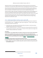
Calculations
For the purposes of the NEM Interconnection Application, the following are formulas used to calculate
CEC-AC nameplate system size (kW) and estimated monthly kWh output:
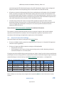
Table 2.2-2: CEC-AC Nameplate Calculation for Inverter based Generation Facilities1
Technology
CEC-AC Nameplate Calculation
Solar PV
(Qty of Modules) x (PTC Rating) x (Inverter Efficiency %) / 1000 = ____ kW
Wind
(Qty of Turbines) x (Power Output) x (Inverter Efficiency %) / 1000 = ____ kW
Fuel Cell
(Qty of Cells) x (Rated Output) x (Inverter Efficiency %) / 1000 = ____ kW
Table 2.2-4: Estimated Monthly kWh Calculation
Technology
Estimated Monthly kWh
Solar PV
Wind
Use the CSI EPBB calculator at www.csi-epbb.com or:
(CEC-AC Nameplate) x 720 x 0.20 = ____ kWh
(CEC-AC Nameplate) x 720 x 0.10 = ____ kWh
Fuel Cell
(CEC-AC Nameplate) x 720 x 0.80 = ____ kWh
1
For Non Inverter based generation facilities, SCE will use the inverter aggregate capacity.
R-850-V5-0414
Appendix B-7
7
NEM Interconnection Handbook: February, 2014 v 5.0
3. Interconnection Review Process
After an initial review to confirm the Application and Single Line Diagram are complete and consistent,
the NEM Interconnection team refers the project to SCE Distribution Engineering for technical review
and approval. Upon referral, the installer is provided notice and contact information for the Distribution
Engineer assigned to the project. At SCE Distribution Engineering’s discretion, an onsite inspection and
commissioning test may be required as part of the technical review – see Section 3.2 for more
information.
The design must be in accordance with:
Rule 21 (PDF)
SCE’s Electric Service Requirements (PDF)
SCE’s Interconnection Handbook (PDF)
the National Electric Code, and
All applicable local codes and ordinances.
SCE strongly encourages the submission of
the Application and Single Line Diagram as
early as possible so that any changes
required as a result of SCE’s technical review
can be incorporated prior to installation.
If the components change from design to
installation, submit revised documents with
subject line ‘EQUIP CHANGE’ prior to
scheduling the final inspection.
Failure to comply with these requirements will result
in potential delay, and any corrections required to
bring the project into compliance with these
requirements will be at the customer’s expense and must be completed before SCE will issue written
authorization to interconnect in the form of a Permission to Operate (PTO) letter.
The purpose of the technical review is to facilitate the safe interconnection of eligible NEM generators
to the SCE electrical distribution system. To ensure the generator interconnection is in compliance with
SCE interconnection requirements, the customer’s generating facility will, at a minimum, be reviewed to
ensure that the generator facility will:
not unintentionally operate in an islanded mode with SCE’s electrical system as required by IEEE
1547 and UL 1741,
have a visible open, lockable disconnect switch and/or rackable breaker for isolation purposes,
comply with SCE’s Electric Service Requirements (ESR).
If the generating facility exceeds the operating capabilities of the distribution system relative to voltage
control, system overload, system operating flexibility or other system condition, it will be required to
mitigate such condition prior to Field Engineering providing technical approval. An NEM customer must
bear the cost of the Interconnection facilities. Please refer to Decision 02-03-057, Rule 21, Section E.4.,
and Public Utilities Code Section 2827(g) for the delineation of cost responsibilities for distribution
modifications versus interconnection facilities.
3.1
Document Review
The following documents are required before SCE will begin the technical review of a proposed
generating facility:
R-850-V5-0414
Appendix B-8
8
NEM Interconnection Handbook: February, 2014 v 5.0
Completed Application Form: see NEM Interconnection Checklists at www.sce.com/nem for
information about which application form is required based on the project size and configuration;
Single Line Diagram: see Section 5.2 for detailed requirements and Appendix A for a sample.
The following additional information may also be required based on the size/configuration of the
proposed system:
Photos of the manual, visibly open, and lockable open AC Disconnect Switch, showing visible contact
separation: see Section 5.3 for manual, visibly open, and lockable open AC Disconnect Switch
requirements;
Plot Plan: see Section 5.3.6 for circumstances when a Plot Plan is required and Appendix B for a
sample.
Inverter Specifications: see Section 5.1 for more information;
Photos of installed SCE provided decals, when applicable: see Section 5.3 for more information.
Line side / supply side taps: Please see Appendix E.
3.2
Commissioning Test
SCE intends to conduct a commissioning test and onsite inspection for as many sites as possible.
Currently all projects greater than 10 kW are subject to a commissioning test, while projects less than 10
kW are evaluated on a case-by-case basis. When a commissioning test is required, a representative of
the installer qualified to operate the equipment must be present.
Before a commissioning test will be scheduled, SCE requires a copy of an Electrical Inspection Release
from the appropriate Authority Having Jurisdiction (e.g. final inspection job card from the local building
and safety department) to ensure that the work on the customer’s side of the meter has been
permitted, meets the requirements of the National Electric Code, applicable local codes and ordinances,
and is therefore safe to energize.
The onsite inspection will ensure that the installation reflects what is shown on the single line diagram
and documents provided by the applicant on the generating facility. Rule 21, Section H, voltage and
frequency requirements will be tested and verified during the commissioning test. Regardless of the
results of the onsite inspection and commissioning test, the customer may not energize the system until
SCE issues a Permission to Operate (PTO) letter.
3.3
Interconnection Study
If, during the course of the initial and supplemental reviews, it is determined that an interconnection
study is required, SCE will determine the study timetable on a case-by-case basis. The interconnection
study will detail any additional interconnection facilities or distribution system modifications that will be
needed to accommodate the applicant’s generating facility. If the generating facility exceeds the
operating capabilities of the distribution system relative to voltage control, system overload, system
operating flexibility or other system condition, it will be required to mitigate such conditions prior to
Field Engineering providing technical approval.
R-850-V5-0414
Appendix B-9
9
NEM Interconnection Handbook: February, 2014 v 5.0
3.4 Review Fees
There are no application and review fees for NEM interconnection requests. Please refer to Rule 21,
Section E.2.c
4 Operating Evaluations
The generator shall not energize or export power to the SCE system during any interruption to the
supply that serves the Point of Common Coupling. The applicant's generation may be operated during
such interruptions only with an open tie to SCE.
Islanding2 with SCE systems will not be permitted under any circumstance.
Technical Approval is based on the following criteria:
15% Rule: the applicant’s generating system combined with existing generation does not exceed
15% of the maximum loading of line section. For more information, please refer to Rule 21 G.1.m.
Overloading: all distribution equipment must not be overloaded by the applicant’s generating
system.
Voltage Operating Levels: the applicant’s generating system must not create a voltage drop or rise
that is outside the allowable operating-voltage bandwidth specified in Rule 21 and Rule 2 (PDF).
System Upgrades: upon review by SCE Distribution Engineering, system upgrades may be required
to allow the system to accommodate the interconnection of the generating facility.
NOTE: For technical analysis defined in this Handbook, SCE Engineering will use the
Aggregate Inverter Capacity.
Please refer to Section 3 (above) for the delineation of cost responsibilities for distribution modifications
versus interconnection facilities.
Following a generation facility disconnect as a result of a voltage or frequency excursion (parameters are
described in Rule 21 Section H 1. a. 2), the generation facility shall remain disconnected until the service
voltage and frequency has recovered to SCE’s acceptable voltage and frequency limits for a minimum of
sixty (60) seconds.
4.1
Normal Voltage Operating Range
To minimize the adverse voltage effects experienced by other customers on SCE’s electric system, any
voltage flicker at the point of common coupling (PCC) caused by the generating facility must not exceed
the limits defined by the “Maximum Borderline of Irritation Curve” shown in the Institute of Electrical
Engineers (IEEE) 519, Rule 2 (PDF), and Rule 21 (PDF).
2
Rule 21, Section C, Definitions.
R-850-V5-0414
Appendix B-10
10
NEM Interconnection Handbook: February, 2014 v 5.0
4.1.1 Limits Specific to Single-Phase Generating Facilities
When connected to a single phase transformer, the generator must be installed such that the
aggregated gross output is balanced between the two phases of the single phase voltage and the
maximum aggregated Gross Ratings for all the Generating Facilities shall not exceed the transformer
rating.
4.1.2 Limits Specific to Three-Phase Generating Facilities
The applicant must balance the demand load and generation as nearly as practical between the two
sides of a three-wire single-phase service and between all phases of a three-phase service.
The difference in amperes between any two phases at the customer’s peak load should not be greater
than 10 percent or 50 amperes (at the service delivery voltage), whichever is greater; except that the
difference between the load on the lighting phase of a four-wire delta service and the load on the power
phase may be more that these limits. It will be the responsibility of the customer to keep the demand
load balanced within these limits.
5 Miscellaneous Requirements
5.1
Inverter
An inverter-based generating facility must meet all required criteria specified in the CPUC’s “Rule 21Generating Facility Interconnections”, IEEE 1547, UL 1741, and SCE’s Interconnection Handbook (PDF).
If the inverter does not meet Underwriters Laboratories Standard UL 1741 certification CSA, OR
specifically meets Section “L” of Rule 21 (PDF), as tested by a nationally recognized testing laboratory
(NRTL) acceptable to SCE with the test reports acceptable to IEEE 1547, Rule 21 (PDF) and SCE,
additional protection requirements and testing may be required.
Inverters listed in the following lists have met UL 1741 and IEEE 1547 standards:
Underwriters Laboratories Standard UL 1741 certification , or
Section “L” of Rule 21 (PDF), as tested by a nationally recognized testing laboratory (NRTL)
acceptable to SCE and the test reports must have been approved by SCE.
The California Energy Commission maintains a certified list of approved inverters at
http://www.consumerenergycenter.org/erprebate/inverter.php. If one of these inverters is used, the
application process is greatly simplified and expedited. If not, the customer may be required to provide
additional details and the utility may need to perform additional studies to determine how the proposed
system will perform under fault conditions and prevent islanding.
Note: SCE may require additional testing for a single installation of multiple CEC-approved inverter units.
To be eligible for CSI credits, the inverter must be listed at http://www.csi-epbb.com/.
R-850-V5-0414
Appendix B-11
11
NEM Interconnection Handbook: February, 2014 v 5.0
Separate single-unit or multiple-unit inverters that do not meet UL 1741 certification or have not been
adequately tested will not be granted commercial operation status and the customer will not be
permitted to interconnect to SCE’s electrical distribution system.
SCE reserves the right to disconnect previously certified interconnected units when Underwriters
Laboratories decertifies the units. SCE may implement an acceptable mitigation procedure for
recertification at the customer’s expense.
5.2
Single Line Diagram
See Appendix A for a sample Single Line Diagram.
The Single Line Diagram shows the path and graphic symbols of the entire electrical system for the site
to provide a good understanding of the connections and component use. “Best” single lines provide, on
one side of the page, a sequence of events such as what happens during an SCE interruption and which
devices close and/or open to return the generation system to normal status. Any and all additional
information necessary to demonstrate compliance with Rule 21 and SCE’s Electrical Service
Requirements (ESR) should be provided.
Depending on the system, the following should be included on the Single Line Diagram:
x
x
Site location/service address (must match address on SCE account and NEM Interconnection
Application);
Detail view of the point of connection to the power grid, specifically showing whether it is on the
utility or customer side of the main breaker - see below for additional requirements that apply
when the point of interconnection is on the utility side of the main breaker (line-side tap) Appendix
E;
Service Panels;
Protective devices: Circuit Breakers, Fuses, CT and PT ratings, if applicable;
Utility meter;
Generation Output Meter(s), of applicant, including built in within component;
Generator(s) make and model;
Detailed component information (characteristics) is included for each component (Voltage and
phase of inverters, transformers, etc.);
Inverter setting for: Under-Voltage, Extreme Under-Voltage, Overvoltage Extreme Voltage, Overfrequency, Under-frequency;
Other Generation type and system size, such as emergency battery backup, diesel generator,
permanently connected generators, etc. including their related interconnection equipment such as
open transition transfer switches, relays and control systems;
Manual, visibly open, and lockable open AC disconnect switch, including make and model (all info
outlined in proposed SLD) – see Section 5.3 for Manual, Visibly Open and Lockable AC Disconnect
requirements;
Code and version to be used for construction and repair, inspection and testing.
R-850-V5-0414
Appendix B-12
12
NEM Interconnection Handbook: February, 2014 v 5.0
Additional Requirements for Line-Side Taps
When the point of connection to the power grid is on the utility side of the main breaker, the Single Line
Diagram must also include:
Protective device information;
Signed PE Stamp.
For Physical connections, please refer to Appendix E
CAUTION ABOUT BROKEN METER SEALS:
Per ESR-5, Section 1.0, (pp 5-7), all enclosures and raceways on the line side (unmetered) or housing
metering equipment shall be sealable. Meter seals shall not be broken by anyone except an
authorized SCE employee.
Per ESR- 6, Section 1.0 (pp 6-5), conductors shall not be rerouted through any metering compartment.
Fused and unfused conductors shall not occupy the same raceway unless they are completely barriered
from each other in a manner acceptable to SCE.
Per ESR- 6, Section 5.0, Figure 6-8 (pp 6-20), except for conductors supplying the instrumenttransformer compartment, and the ground bus, no other conductors or devices shall be installed in, or
routed through, the compartment or the sealed area above the compartment. The ground bus shall not
infringe on utility-compartment space, or reduce any clearances. Customer connections to the ground
bus shall be allowed in the instrument transformer compartment.
5.2.1 Visible Open AC Disconnect Switch requirements for generation
interconnection to distribution voltages 34.5KV or below 3
Per SCE guidelines, a visible open, lockable AC Disconnect is required for all of the following aggregate
generating facilities:
All Commercial
All Residential Non Self-Contained Meters
All Line-Side Taps (additional overcurrent protection required)
Refer to Rule 21 Section H.1.d and SCE’s Interconnection Handbook (PDF) for Visible open Disconnect
requirements.
5.2.2 Disconnects must be reviewed and approved by Field Engineering.
Location of AC Disconnect
In order for SCE to operate and maintain the distribution system safely and reliably, it is mandatory that
all electrical sources to the SCE’s distribution system have the ability to
If you come across a
be disconnected from the system with a single, visible open and
broken meter seal,
lockable switching device. Having the ability to disconnect and to
report it immediately
to (800) 655-4555.
secure the disconnection of the various electrical sources will allow
SCE’s workers to safely perform the required maintenance to the
3
SCE’s Interconnection Handbook provides the requirements for voltage greater than 34.5KV.
R-850-V5-0414
Appendix B-13
13
NEM Interconnection Handbook: February, 2014 v 5.0
distribution system by removing, tagging and taking the required clearances to the system where
maintenance is to be performed. SCE’s distribution system is designed with switches and other devices
that can be used to disconnect the SCE source to any section of the distribution system. However, in
order to achieve the required, complete isolation from all the sources, the generation facility sources
that are connected to the distribution system must also have the capability of being securely
disconnected with a single, visible open and lockable switching device. While SCE acknowledges that in
some cases, installing the required disconnecting device may significantly increase the cost of the
interconnection, SCE must ensure that the system is safe to operate and maintain and thus must require
the appropriate disconnecting device. SCE will accept the following alternatives to installation of a
visible open and lockable disconnect in order to maintain the ability to disconnect the generating
facilities from the distribution system:
5.2.3 Self-Contained Meter4 with one main switch (CB)
For these facilities, SCE can utilize the SCE revenue meter to disconnect the generation and load from
the SCE distribution system. See figure-1 for typical system configuration. In order to use this option,
the following requirements must be met:
1. Facility must have a main breaker that can be operated by the customer on the same metering
switchboard (meter panel) as the revenue meter.
2. Customer must agree that when it is necessary to disconnect the generating facility by opening the
main CB and then removing the revenue meter, the customer will also experience an outage to the
customer’s facility until the meter is re-installed.
Restrictions:
For the facilities or the conditions below, the option of removing the revenue meter for disconnection
purposes is not available and the customer must install a visible open and lockable disconnect
adjacent to the PCC or an approved location that should be on line of sight with approved signage and
on a single disconnecting switching device as required by Rule 21 and SCE’s Interconnection
Handbook.
a) Facilities which do not have a main CB in the metering enclosure.
b) Generating facilities that are proposing to connect to the source side of the CB (when allowed)
c) When customers do not agree on facility outage when required to disconnect the generator from
the distribution system.
4
Reference SCE’s Electrical Service Requirements for information on Self Contained Meter
R-850-V5-0414
Appendix B-14
14
NEM Interconnection Handbook: February, 2014 v 5.0
Step #2: SCE to
remove the
Meter for
isolation
M
Main CB
Step #1:
Customer Open
Main CB
SCE Secondary Service cable
Generating Facility
Typical self contained meter per SCE’s Electrical Service
Requirements
ͳǦ
Ǧ
5.2.4 Non Self-Contained Meter – Secondary Voltage Connection
These generation facilities cannot be disconnected by simply removing the revenue meter as the
metering is achieved by current transformers (CTs). Refer to figure 1.2 for typical installation. These
types of installations are typically utilized for medium-sized commercial or industrial customers. For
these types of systems, the following are the disconnect device requirements:
1. Must comply with Rule 21section H.1.d – Visible Open Disconnect Requirement and SCE’s
Interconnection Handbook section 5.11.1- Manual disconnect.
2. One single disconnect is to be used to disconnect all generation at a facility.
a. When adding additional generation to a facility that currently has generation at the facility, the
added generation must be connected to the existing disconnecting device.
3. The visible open disconnect must be adjacent to the Point of Common Coupling (PCC) or an
approved location that should be in line of sight with approved signage and must comply with
access requirements per Rule 21section H.1.d.
a. Inside the same electrical metering room
b. Immediately outside the electrical metering room
4. Location of visible open disconnect must be approved by SCE prior to installation.
a. Plot plan outlining the locations of the visible open disconnect must be provided in the
interconnection request.
R-850-V5-0414
Appendix B-15
15
NEM Interconnection Handbook: February, 2014 v 5.0
M
PCC
Main CB
Visible &
Lockable
Generating Facility
SCE Secondary Service cable
Typical non-self contained meter switchboard per SCE’s
Electrical Service Requirements
ʹǦ
ǦǦ
5.2.5 Primary Service Voltage Connections
These types of installations are typically utilized by large customers or by customers that have a campus
style electrical system. For these types of installations, the generation is typically installed on a panel
fed by the customer’s transformers (see figure - 3). For these types of installations, it becomes
extremely difficult to comply with the “one single disconnect at the PCC” requirement. SCE’s main
intent is to have the ability to remove the generation from SCE’s distribution system so that SCE
personnel may work on the distribution system safely. To this extent, SCE and the customer can agree
to use the customer’s main rackable breaker to provide the disconnecting means when it is necessary to
remove the generation from the SCE’s distribution system. The following are the requirements:
1. Facility must have a main breaker that can be opened and racked-out by the customer.
a. SCE’s clearance policies can take a clearance to a customer CB when SCE can take control over
the CB. This would be accomplished by witnessing that the CB was racked out and by applying
SCE’s lock and tagging procedures.
2. Customer must agree that when necessary to disconnect the generating facility by opening and
racking-out the CB, the customer will also experience an outage to the customer’s facility.
a. Customer must provide a letter on their company letterhead stating agreement with this
concept.
Restrictions:
For the facilities or the conditions below, the option of using the main breaker for purposes of
disconnecting the generation facility is not available and the customer must install a visible open and
lockable disconnect as required by Rule 21 and SCE’s Interconnection Handbook near the PCC and on a
single disconnecting device.
a) Facilities that do not have a main CB that is capable of being racked-out.
R-850-V5-0414
Appendix B-16
16
NEM Interconnection Handbook: February, 2014 v 5.0
x
Customer may replace the CB section with a rackable CB in order to meet the
requirement.
b) When customer does not agree on facility outage when isolating the generator from the
distribution system.
SCE Pull
Section
CB Section
1) SCE to De-Energize
Customer service by
opening source switch
Metering
Section
Revenue
Meter
PCC
Main CB
Rackable
M
Generating Facility
Main CB
To Sub
Customer
Load
1
2
3
4
Circuit Coninues
3) SCE has clearance on
this section of line
2) Customer to Open
and Rock-out CB and SCE
to verify and lockout the
CB with SCE Locks. (SCE
takes control of the CB)
Typical high voltage per SCE’s Electrical Service
Requirements
͵Ǧ
5.2.6 Plot Plan Requirement
See Appendix B for a sample Plot Plan.
If the manual, visibly open, and lockable AC disconnect is required, a Plot Plan must be provided to SCE
Distribution Engineering for review, showing the location of the manual visibly open and lockable open
AC disconnect switch with reference to the utility meter.
5.2.7 Circumstances when AC Disconnect May be Opened by SCE
The manual, visibly open, and lockable open AC Disconnect Switch or rackable circuit breaker may be
operated by SCE under the following circumstances:
Pre-emergency or emergency conditions on the SCE system.
A hazardous condition is revealed by an SCE inspection.
To eliminate a condition that constitutes a potential hazard to SCE personnel or the general public.
When protective device tampering is discovered.
A generator-owner has failed to make available records of Verification tests and maintenance of its
protective devices.
A generator-owner’s system interferes with SCE equipment or equipment belonging to other SCE
customers.
A generator owner's system is found to affect quality of service of adjoining customers.
R-850-V5-0414
Appendix B-17
17
NEM Interconnection Handbook: February, 2014 v 5.0
5.3
Signage Requirements
SCE requires decals or permanent signage to be installed on generation facilities in order to identify
customers that have generation onsite. A photograph with the installed decals must be submitted to the
NEM Interconnection team with the final Permit Inspection (see section 2.1). SCE will verify the decal
installation during the final technical approval by local Field Engineering or Service Planning.
Decals that will be installed on the customer’s
main service panel
Decals that will be installed on the AC Disconnect
to be used for utility isolation of the generator
You have the option to receive the decals by the following method:
1. You may elect to have up to 20 sets of decals sent to you. Please send a self-addressed stamped
envelope with sufficient postage to mail a total weight of 3.4 ounces to the following address:
Attn: SCE Field Engineering Support
2885 West Foothill Blvd.
Rialto, CA 92376
2. You may contact the Field Engineer assigned to your project to coordinate decal pick up at the
local service center.
Once you have identified a vendor to make each type of decal, please send a sample set with vendor
and contact information for approval. You can have an approved vendor make SCE decals in bulk at your
convenience. Please see Appendix F for instructions.
SCE decal placement does not authorize the generation facility to operate in parallel. You
may only turn on your system once you have received official notification from SCE
R-850-V5-0414
Appendix B-18
18
NEM Interconnection Handbook: February, 2014 v 5.0
5.4
Telemetering
Please refer to section 7 of SCE’s Interconnection Handbook) for information about telemetry
requirements.
5.5
Net Generation Output Meter (NGOM)
A Net Generation Output Meter (NGOM) may be required as indicated in the applicable Rate Schedule –
see section 1 for a list of Rate Schedules. Please see Figure 4 for additional requirements.
For Virtual Net Energy Metering projects, either Schedule NEM-V or Schedule MASH-VNM, a NGO
meter will be required and paid for by the customer, also the customer will provide and install the NGO
meter socket per the ESR. The point of interconnection must be made in parallel to other SCE revenue
meters and not in SCE sealed sections. Refer to the Electrical Service Requirements section 1.12., and
Figure 5 for wiring instructions of the NGO socket.
5.5.1 AC Disconnect requirement for NGO meter sockets
When a NGO customer meter socket is installed, a line side and a load side ganged operated, visible
open, lockable AC Disconnect shall be installed. See Figure 4.
x
x
For NGO meter socket rated at greater than 600 V, the AC Disconnects shall be installed directly
adjacent to the NGO meter socket.
For NGO meter sockets rated at 600 V or below, the AC Disconnects shall be installed in line of
sight of the NGO meter socket.
These AC Disconnects may be in addition to the singular AC Disconnect to isolate the entire generation
facility.
R-850-V5-0414
Appendix B-19
19
NEM Interconnection Handbook: February, 2014 v 5.0
Note 1: For metering
purposes, the generator
shall be connected to the
line side of the NGO socket
M
Load Side Visible **
& Lockable AC
Disconnect
Main CB
PCC
Line Side Visible **
& Lockable AC
Disconnect
M
Generating Facility
Net Generation
Output Meter
Socket
Note 2: Please reference
the ESR section 5 for
Meter socket
requirements
** For voltage of 600 V and below, the
isolation AC Disconnects shall be in line of
site of the NGO meter socket
For voltage of greater than 600 V, the
isolation AC Disconnects shall be directly
adjacent to the NGO meter socket
SCE Secondary Service cable
Typical self contained meter per SCE’s Electrical Service
Requirements
ͶǦ
Ǧ
Note 1: For metering purposes, the generator
shall be connected to the LOAD SIDE of the NGO
socket
Load Side Visible ** & Lockable AC
Disconnect
Line Side Visible ** & Lockable AC
Disconnect
SCE
M
Generating Facility
Net Generation Output Meter
Socket
** For voltage of 600 V and below, the
isolation AC Disconnects shall be in line of
site of the NGO meter socket
For voltage of greater than 600 V, the
isolation AC Disconnects shall be directly
adjacent to the NGO meter socket
Note 2: Please reference the ESR section 5
for Meter socket requirements
Figure 5-Wiring of a NGO meter socket for Virtual Net Metering projects
R-850-V5-0414
Appendix B-20
20
NEM Interconnection Handbook: February, 2014 v 5.0
5.6
Generating Systems with Battery Back-Up
Back-up generators are typically used to provide electrical power to the facility during electrical outages
of SCE’s electrical grid. There are several forms of back-up generation including battery back-up, diesel
generators, fly-wheels, etc.
Battery back-up systems when used in conjunction with an NEM project must be designed to be in an
isolated mode and not parallel with SCE system under any condition. Typically this isolation mode can be
accomplished via use of an “open transition” transfer switch but other means can be used to accomplish
the isolation requirements. These types of system will require SCE approval and may also require a
separate Rule 21 interconnection request.
5.7
Secondary Network Interconnection
Interconnection of NEM facilities onto SCE’s secondary network distribution system is permitted.
However, due to the complexity of secondary networks, additional requirements must be met to ensure
continued reliable operation of the network.
In addition to standard NEM requirements, NEM interconnections must use one of the following to
ensure non-export to the SCE secondary network:
(Preferred) An under-power relay (minimum-import relay) should be installed to monitor power
flow at the PCC. The relay should be set to disconnect the NEM generator from the SCE system
when input power at the PCC falls below Rule 21, G.1.i. requirements (5% of the Generating
Facility’s total Gross Nameplate Rating, with a maximum 2.0 second delay).
A reverse power relay should be installed to monitor power flow at the PCC. The relay should be set
to disconnect the NEM generator from the SCE system when reverse power flow at the PCC falls
exceeds Rule 21, G.1.i. requirements (0.1% of the service transformer’s rating, with a maximum 2.0
second delay).
Install dynamically controlled inverters (DCI) that monitor power flow at the PCC and will initiate a
reduction of power output from the NEM to maintain a minimum import level.
6 Protection Requirements
The interconnection of a new NEM generation facility to the SCE distribution system must not degrade
any of the existing SCE protection and control schemes nor lower the existing levels of safety and
reliability to other customers.
Generating Facilities operating in parallel with SCE’s Distribution system shall be equipped with the
following Protective Functions to sense abnormal conditions on SCE’s Distribution System and cause the
Generating Facility to be automatically disconnected from SCE’s Distribution System or to prevent the
Generating Facility from being connected to SCE’s Distribution System inappropriately:
Over and under voltage trip functions and over and under frequency trip functions.
A voltage and frequency sensing and time-delay function to prevent the Generating Facility from
energizing a de-energized Distribution System circuit and to prevent the Generating Facility from
R-850-V5-0414
Appendix B-21
21
NEM Interconnection Handbook: February, 2014 v 5.0
reconnecting with SCE’s Distribution System unless SCE’s Distribution System service voltage and
frequency are within normal operating limits and are stable for at least 60 seconds.
A function to prevent the Generating Facility from contributing to the formation of an Unintended
Island, and cease to energize SCE’s Distribution System within two seconds of the formation of an
Unintended Island (Island; Islanding: A condition on SCE’s Distribution System in which one or more
Generating Facilities deliver power to customers using a portion of SCE’s Distribution System that is
electrically isolated from the remainder of SCE’s Distribution System.)
The Generating Facility shall cease to energize SCE’s Distribution System for faults on SCE’s
Distribution System circuit to which it is connected (IEEE 1547-4.2.1). The Generating Facility shall
cease to energize SCE’s Distribution circuit prior to re-closure by SCE’s Distribution System
equipment (IEEE 1547-4.2.2).
Please reference SCE’s Interconnection Handbook for additional information.
The customer’s system-protection facilities are at the customer’s expense, and must be installed,
operated, and maintained in accordance with all the applicable regulatory requirements and in
accordance with the design and application requirements of this Handbook.
6.1
Inverter Protection Settings
Approved voltage and frequency setting per SCE’s Rule 21 below:
If inverter is 30KW or below, protection settings approved if inverter is UL listed (all CEC approved
inverters meet this guideline)
If inverter is larger than 30kW, protection settings are field adjustable
o Verify that it is UL listed
o Verify settings on each inverter during commissioning test by installer displaying settings on
connected computer or on inverter panel.
If settings cannot be verified during a commissioning test, obtain a letter from the inverter manufacturer
providing the inverter settings and their respective serial number. Distribution Engineering will verify the
proposed settings to ensure that they meet Rule 21, Section H requirements -- see Appendix C.
Table 7.1-1 Voltage Relay Settings
Maximum Timing
Element
Element Name
Settings (< or =)
% of Nominal
120V
Base
480V
Base
208V
Base
Cycles
Seconds
27
Extreme Under-Voltage
50%
60
240
104
10
0.167
27
Under-Voltage
88%
105.6
422.4
183
120
2
59
Over-Voltage
110%
132
528
228.8
60
1
59
Extreme Over –Voltage
120%
144
576
249.6
10
0.167
Note: Producer can set relays more stringent than required by Rule 21. Such is the case in inverter
systems.
R-850-V5-0414
Appendix B-22
22
NEM Interconnection Handbook: February, 2014 v 5.0
Table 7.1-2 Frequency Relay Trip Settings
Element
Element Name
Settings
Maximum Timing
Cycles
Seconds
81O
Over-Frequency
> 60.5 HZ
10
0.167
81U
Under-Frequency
< 59.3 HZ
10
0.167
Unless otherwise required by SCE, a trip frequency of 59.3 Hz and a maximum trip time of 10 cycles shall
be used.
6.1.1 Ground-Fault-Sensing and Stabilization
When required by SCE’s Interconnection Handbook (PDF), a ground-fault-sensing scheme detects SCE’s
ground faults and trips the generator breaker or the generator’s main circuit breaker, preventing the
generator from continuously contributing to the ground fault.
Ground-fault-sensing scheme will consist of either a ground detector or ground bank depending on the
configuration of SCE’s power system.
7 Definitions
Accessible: A device that is accessible to SCE maintenance personal consistent with Rule 21 (PDF)
requirements.
Anti-Islanding: A control scheme installed as part of the Generating or Interconnection Facility that
senses and prevents the formation of an Unintended Island.
Island; Islanding: A condition on SCE’s Distribution System in which one or more Generating Facilities
deliver power to customers using a portion of SCE’s Distribution System that is electrically isolated from
the remainder of SCE’s Distribution System.
Line-Side Tap: A point of interconnection on the utility, or line side of the main breaker.
Load-Side Tap: A point of interconnection on the customer, or load side of the main breaker.
Lockable: The disconnect must have provisions for a common 3/8” padlock, used as part of normal SCE
maintenance lockout procedure. (see Section 5.3 Manual, Visibly Open and Lockable AC Disconnect
Switch)
Non-Islanding: Designed to detect and disconnect from a stable Unintended Island with matched load
and generation. Reliance solely on under/over voltage and frequency trip is not considered sufficient to
qualify as Non-Islanding.
Non -Self Contained Meter: An SCE revenue grade meter at a customer panel that uses external current
transformers to measure the flow of current.
R-850-V5-0414
Appendix B-23
23
NEM Interconnection Handbook: February, 2014 v 5.0
Standard: Located on the customer’s premise, must use UL listed inverter(s), with a point of
interconnection on the customer side of the main circuit breaker, does not require a Net Generation
Output meter, and is the sole generator onsite (no backup systems, no battery backup systems, etc.)
Unintended Island: The creation of an Island, usually following a loss of a portion of SCE’s Distribution
System, without the approval of SCE.
Visible Open: Visible means visible break; when the disconnect is in the open position, there is a visible
separation between the contacts, and the separation may be observed without disassembling the
device. Typically, this switch contains visible blades inside an enclosure, an external lever, and a positive
indication that the switch is in the off position. (see Section 5.3 Manual, Visibly Open and Lockable AC
Disconnect Switch)
R-850-V5-0414
Appendix B-24
24
R-850-V5-0414
Appendix A: Sample Single Line Diagram
Appendix B-25
25
NEM Interconnection Handbook: February, 2014 v 5.0
R-850-V5-0414
Appendix B: Sample Plot Plan
Appendix B-26
26
NEM Interconnection Handbook: February, 2014 v 5.0
NEM Interconnection Handbook: February, 2014 v 5.0
Appendix C: Inverter Settings Request
R-850-V5-0414
Appendix B-27
27
NEM Interconnection Handbook: February, 2014 v 5.0
Appendix D: Maximum Borderline of Irritation Curve
R-850-V5-0414
Appendix B-28
28
NEM Interconnection Handbook: February, 2014 v 5.0
Appendix E: Supply Side / Line Side connections
To: ___________ SCE Project #: ___________
SCE has received the application for a ___KW solar generating facility located at ________________.
The single line for the proposed project indicates that the proposed method of interconnection to the
SCE system is to connect the generating facility to the source side of the existing customer’s main
breaker (Line Side Tap). This proposed method of interconnection requires the existing interconnecting
switchgear equipment (busses, connectors, termination points, etc.) to be modified in order to connect
the generation on the source side of customer’s main circuit breaker. Such modifications could
compromise the UL certification of the existing switchgear and could compromise the ratings and
withstand capabilities that the switchgear was originally designed for. SCE strongly encourages the
customer to modify its proposed method of interconnection, and interconnect the generating facility to
the load side of the main circuit breaker in accordance with the original intent of the existing switchgear.
SCE considers the project’s proposed method of interconnection to be a potential safety issue because
of the modification of the switchgear. To ensure that the project’s interconnection facilities meet SCE’s
safety requirements, SCE must receive verification of UL compliance for the modifications to the existing
switchgear. This can be accomplished in the following ways:
1. A copy of the attached verification signed by the inspecting authority, acknowledging the
following: (1) that the existing customer switchgear has been altered to allow the
interconnection of the generating facility to the source side of the customer’s main breaker;
and (2) that the altered customer switchgear continues to meet UL certification
requirements or that the modified equipment has been recertified for its new configuration.
2. A document from the manufacturer of the existing panel indicating that the proposed
modification or connection to the source side of that panel does not compromise the UL
rating of the panel.
3. A UL certification of the proposed modification or connection to the source side of the main
circuit breaker of the existing panel
SCE must receive one of these verifications before it will approve the generating facility for
interconnection to SCE’s distribution system via the source side of the existing customer’s main breaker
(Line Side Tap). It should be noted that in addition to the requirements above, the customer must
comply with existing requirements including a P.E stamped Single Line, plot plan, equipment
requirement, etc.
Southern California Edison
Friendly Field Engineer
909-555-5555
[email protected]
R-850-V5-0414
Appendix B-29
29
NEM Interconnection Handbook: February, 2014 v 5.0
Return to:
Southern California Edison
Friendly Field Engineer
909-555-5555
[email protected]
City / Authority Having Jurisdiction:______________________
SCE Project #:________________________
I, _____________________, hereby certify that:
1.
The existing customer switchgear has been altered to allow the interconnection of the
generating facility to the source side of the customer’s main breaker; and
2.
The altered customer switchgear continues to meet UL certification requirements or that
the modified equipment has been recertified for its new configuration.
Name & Title:_______________________________ Signature:______________________ Date: __________
R-850-V5-0414
Appendix B-30
30
NEM Interconnection Handbook: February, 2014 v 5.0
Appendix F: Vendor Decal instructions
Once you have identified a vendor to make each type of decal: Send this template to have a
vendor make the decals to be installed on your generation project. This is the actual size of the
decals.
For decals that have to be placed on the customer’s panel:
Small Generator Labels 3" x 4"
Forms: 15-40-A
Specs: 3" x 4", yellow, green,
red and black on 3M premium
vinyl with 3M #3980 clear coat
and scored backing
For decals that have to be placed on AC Disconnects
Small Generator Labels 3" x 4"
Forms: 15-43-A
Specs: 3" x 4", yellow, green,
red and black on 3M premium
vinyl with 3M #3980 clear coat
and scored backing
R-850-V5-0414
Appendix B-31
31
NEM Interconnection Handbook: February, 2014 v 5.0
Once the decals are made, please send a sample set to:
Attn: SCE Field Engineering Support
2885 West Foothill Blvd.
Rialto, CA 92376
Please also provide your contact information and your vendor information.
Once the decals are approved by SCE, please install them as per the diagrams below for each project as
part of your application package.
NOTE: The examples above are intended to portray typical customer equipment. If you have any questions or
concerns about signage placement, contact the Field Engineer directly.
R-850-V5-0414
Appendix B-32
32