1
WVU DESIGN GUIDELINES AND CONSTRUCTION MANUAL
DIVISION 23 – HVAC
SECTION 230900 – INSTRUMENTATION AND CONTROLS
PART 1 GENERAL ..................................................................................................................... 3
1.1 RELATED DOCUMENTS ............................................................................................... 3
1.2 OVERVIEW...................................................................................................................... 3
1.3 RELATED SECTIONS..................................................................................................... 3
1.4 REFERENCES .................................................................................................................. 3
1.5 DEFINITIONS .................................................................................................................. 4
1.6 MANUFACTURERS........................................................................................................ 4
1.7 SCOPE OF WORK ........................................................................................................... 5
1.8 SUBMITTALS .................................................................................................................. 7
1.9 COORDINATION WITH OTHER CONTRACTORS .................................................. 14
1.10 CONTRACTOR (CSC) EXPERIENCE AND PERFORMANCE ................................. 15
1.11 WARRANTY & SERVICE ............................................................................................ 15
1.12 COMPLY WITHOUT EXCEPTION………………………………..……………...….16
PART 2A PRODUCTS, HARDWARE........................................................................................ 17
2A.1 LAPTOP COMPUTER……………………………………………………………….17
2A.2 NETWORKING/COMMUNICATIONS..................................................................... 18
2A.3 BUILDING SYSTEMS INTEGRATION ................................................................... 19
2A.4 GLOBAL BUILDING CONTROLLER /ROUTER.................................................... 20
2A.5 APPLICATION CONTROLLERS .............................................................................. 22
2A.6 SERVER....................................................................................................................... 24
2A.7 LAPTOP COMPUTER ................................................................................................ 24
2A.8 FIELD HARDWARE/INSTRUMENTATION ........................................................... 25
2A.9 SENSORS .................................................................................................................... 26
2A.10 THERMOSTATS......................................................................................................... 28
2A.11 VALVE AND DAMPER ACTUATORS .................................................................... 29
2A.12 CONTROL VALVES .................................................................................................. 30
PART 2B PRODUCTS, SOFTWARE ......................................................................................... 31
2B.1 SYSTEM SOFTWARE OVERVIEW ......................................................................... 31
2B.2 SYSTEM CONFIGURATION .................................................................................... 31
2B.3 GRAPHIC PROGRAMMING..................................................................................... 32
2B.4 DIRECT DIGITAL CONTROL SOFTWARE............................................................ 33
2B.5 SOFTWARE USER INTERFACE .............................................................................. 34
PART 3 EXECUTION ............................................................................................................... 42
3.1 EXAMINATION............................................................................................................. 42
3.2 GENERAL INSTALLATION ........................................................................................ 42
3.3 WIRING INSTALLATION ............................................................................................ 42
3.4 CONTROL DEVICE INSTALLATION......................................................................... 43
3.5 CONNECTIONS ............................................................................................................. 44
3.6 CONTROL POWER ..................................................................................................... 444
3.7 IDENTIFICATION ......................................................................................................... 45
3.8 TRENDS.......................................................................................................................... 45
[Rev - 0] 05/06
230900 - 1
WVU DESIGN GUIDELINES AND CONSTRUCTION MANUAL
DIVISION 23 – HVAC
3.9 ALARMS......................................................................................................................... 46
3.10
SCHEDULES............................................................................................................... 46
3.11
ACCEPTANCE OF COMPLETED BAS INSTALLATION...................................... 46
3.12
TRAINING................................................................................................................... 49
3.13
ADJUSTING AND CLEANING................................................................................. 50
PART 4 SEQUENCES OF OPERATION ................................................................................. 50
[Rev - 0] 05/06
230900 - 2
WVU DESIGN GUIDELINES AND CONSTRUCTION MANUAL
DIVISION 23 – HVAC
PART 1 – GENERAL
1.1
Related Documents
A.
1.2
1.3
Overview
A.
This document contains the specification and input/output summaries for the
Building Automation System (BAS) at WVU. The system architecture shall utilize
intelligent distributed control modules, located at each site, which communicate
over a local controller network. The BAS shall provide Direct Digital Control
(DDC), monitored via Microsoft Internet-Explorer, the thin-client user interface.
This BAS for the air conditioning, heating and ventilating systems shall interface
with other microprocessor based building subsystems as specified.
B.
The system will consist of an open architecture that utilizes EIA standard 709.1, the
LonTalk™ protocol, as the common communication protocol between all
controllers and integral ANSI / ASHRAE™ Standard 135-2001, BACnet
functionality to assure interoperability between all system components. Both the
LonTalk™ protocol and the ANSI / ASHRAE™ Standard 135-2001, BACnet
protocol are required to assure that the project is fully supported by the two HVAC
open protocols to reduce future building maintenance, upgrade, and expansion
costs.
C.
It is the intent of this document that all control points, including those at the
Application Level, be brought to the Ethernet Network Level.
D.
Contractor Alert: Many aspects of the installation and implementation of this
project require approval by the University’s Physical Plant before the BAS
installation shall proceed.
Related Sections
A.
1.4
Drawings and general provisions of the Contract, including General Conditions of
the Contract, General Conduct of the Work and Special Requirements, and Division
1 Specification Sections, apply to this Section.
3rd-Party Interfacing is required on this project for sub-systems such as:
1.
Roof Top Unit(s)
2.
Chiller(s)
3.
Variable Frequency Drive(s)
4.
Lighting Controls
5.
Electrical Monitoring
6.
OTHER as specified by WVU
References
A.
ANSI/ASHRAE 135-2001: BACnet - A Data Communication Protocol for
[Rev - 0] 05/06
230900 - 3
WVU DESIGN GUIDELINES AND CONSTRUCTION MANUAL
DIVISION 23 – HVAC
Building Automation Systems: This shall include the Standard and all published
Addenda.
B.
1.5
Lon - An open architecture that utilizes EIA standard 709.1, the LonTalk™
protocol, as the common communication protocol between all peer-to-peer
controllers.
Definitions
A.
BAS refers to the Building Automation System. (In the past, this may have been
referred to as CCS, Central Control System, EMS, Energy Management System, or
ATC, Automatic Temperature Control.)
B.
CSC refers to the Control System Contractor. The CSC is the Contractor
responsible for the implementation of this Section of the Specifications.
C.
Gateway refers to the interface (hardware and/or software) to provide seamless
integration by non-BAS equipment manufacturers. Refer to paragraph 2A.2 “BAS
Interfacing with 3rd-Party Sub-systems”.
D.
I/O refers to Input/Output. Thus, "I/O device" means "Input/Output device".
E.
IP refers to the Internet Protocol.
F.
OEM stands for Original Equipment Manufacturer, and refers to the manufacturer
of the equipment being provided that includes a microprocessor based building subsystem [RTU(s), Chiller(s), VFD(s), Lighting Controls, and/or Electrical
Monitoring] for this Project.
G.
Object Table(s) refers to the detailed listing(s) of BACnet objects and the
functional requirements using the various operator interfaces for the system. In the
past, this/these may have been referred to as "Points List(s)" and "I/O Summary".
Note: For systems using Peer-to-Peer Lon Communications, only the information
supplied at the Ethernet level will be BACnet.
1.6
H.
On-line refers to accessibility via the thin-client user interface.
I.
Thin-client User Interface refers to the software program Microsoft Internet
Explorer.
J.
WVUIT refers to WVU’s Telecommunications and Networking Services.
K.
OWS refers to an Operator Work Station, also seen as Operator Workstation.
L.
“University’s Physical Plant Group” refers to University employees designated
by the Office of Facilities Management.
Manufacturers
A.
Automated Logic Corporation (ALC).
B.
Invensys Controls (formerly Siebe / Barber Colman)
C.
Siemens Building Technologies (SBT)
[Rev - 0] 05/06
230900 - 4
WVU DESIGN GUIDELINES AND CONSTRUCTION MANUAL
DIVISION 23 – HVAC
D.
1.7
No other Manufacturers are allowed.
Scope of Work
A.
B.
C.
Control System Contractor's (CSC) Responsibilities:
1.
The CSC shall furnish and install all necessary hardware, wiring, pneumatic
tubing, computing equipment and software required to provide a complete
and functional system necessary to perform the design intent given in the
sequences of operation, and as defined in this specification.
2.
The CSC is fully responsible to integrate 3rd party equipment sub-systems
when supplied with a BACnet, Lon, or Modbus interface. The CSC and the
3rd party equipment supplier shall work together to ensure proper integration
of the systems. All costs associated with the work of this Section shall be
included in the CSC’s contract.
3.
The CSC shall coordinate the CSC’s work with other trades.
System Requirements
1.
All material and equipment used shall be standard components, regularly
manufactured and available, and not custom designed especially for this
project. All systems and components, except site-specific software, shall
have previously been thoroughly tested and proven in actual use prior to
installation on this project.
2.
The system architecture shall be fully modular permitting expansion of
application software, system peripherals, and field hardware.
3.
The system, upon completion of the installation and prior to acceptance of
the project, shall perform all operating functions as detailed in this
specification.
Equipment
1.
System Hardware
a.
[Rev - 0] 05/06
The CSC shall provide the following:
(1)
Control modules.
(2)
All relays, switches, sensing devices, indicating devices,
and transducers required to perform the functions listed in
Object Table(s).
(3)
All monitoring and control wiring and air tubing.
(4)
For this project, the CSC shall provide integration gateway
modules and software to interface with 3rd party equipment
as specified by the Owner; examples include RTU(s),
Chiller(s), VFD(s), Lighting Controls, and/or Electrical
Monitoring.
230900 - 5
WVU DESIGN GUIDELINES AND CONSTRUCTION MANUAL
DIVISION 23 – HVAC
Note: If possible 3rd party equipment manufacturers will supply
controllers utilizing BACnet IP, Lon, or Modbus, communications,
limiting the gateway modules required by the CSC.
2.
D.
E.
System Software
a.
The CSC shall provide all software identified in this specification.
The database required for implementation of these specifications
shall be provided by the CSC, including point descriptor, alarm
limits, calibration variables, on-line graphics, reports and point
summaries. The CSC shall provide and create the system using the
latest software release, at the time of Shop Drawing approval.
b.
Site-license: All required software site-license for this project shall
be furnished by the CAC.
Object Table(s)
1.
The system as specified shall monitor, control, and calculate all of the
points/objects and perform all the functions as listed in sequences of
operation and as shown in control diagrams in this specification.
2.
All objects shall be exposed as BACnet Objects, with full Functional
Profile information and XIF files (Lon), to facilitate BACnet IP
communication between multiple vendors.
Codes and Regulations
1.
2.
3.
[Rev - 0] 05/06
All electrical equipment and material and its installation shall conform to
the current requirements of the following authorities:
a.
Occupational Safety and Health Act (OSHA)
b.
National Electric Code (NEC)
c.
National Fire Code
d.
International Mechanical Code
e.
International Building Code
f.
International Plumbing Code
All distributed, application controllers supplied shall be in compliance
with the following listings and standards:
a.
UL916 for Open Energy Management
b.
FCC Part 15, Sub-Part B, Class A
c.
CE Electro Magnetic Compatibility
The control system manufacturer shall have quality control procedures for
design and manufacture of environmental control systems for precise
control and comfort, indoor air quality, HVAC plant operation, energy
savings and preventative maintenance.
230900 - 6
WVU DESIGN GUIDELINES AND CONSTRUCTION MANUAL
DIVISION 23 – HVAC
4.
1.8
Where two or more codes conflict, the most restrictive shall apply.
Nothing in this specification or related documentation shall be construed
to permit work not conforming to applicable codes.
F.
Building Ethernet Connection Cabling: The CSC shall provide building
compatible Ethernet cabling, (typically CAT-5), between Global Building
Controller(s)/Router(s) and the Building Telecommunications Closet. The
building Ethernet Connection shall be provided by the University (cooperation
between Physical Plant and WVUIT). The CSC shall provide repeaters between
Global Building Controllers /Routers and the Building Ethernet Connection as
required. Final Building Ethernet Connection shall be coordinated with the
University’s Physical Plant Group.
G.
Major Systems Cabling: The CSC shall provide all required cabling, between the
Global Building Controller location and each location of an Air Handler, Heating
System, and/or Chilled Water System Panel
H.
The CSC shall provide all object mapping and programming to expose all objects to
the network level, and shall coordinate object naming conventions and network
map requirements with the University’s Physical Plant Group. The naming
convention shall be submitted with the BAS Shop Drawings for review and
approval by the University’s Physical Plant.
I.
The CSC shall provide a circuit from an existing Normal/Emergency power panel
or an UPS for the Global Building Controller/Routers and, if necessary, repeaters
and Application Controllers monitoring emergency equipment. A UPS is to be
used only if Normal/Emergency power is not available in the building.
J.
The CSC shall provide router and software to route BACnet messages over the
existing Campus Ethernet infrastructure using BACnet standard Annex J routing
(BACnet over IP). Existing Campus Ethernet infrastructure has multiple subnets
and is capable of routing IP messages.
K.
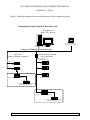
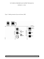
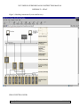
Refer to Figure 1, Figure 2 and Figure 3 at the end of this Section for a graphical
indication of the Scope of Work, as it relates to the campus infrastructure and OEM
equipment.
Submittals
A.
Submit under provisions of Division 1.
1.
A block diagram of the system showing each console item, and each
Distributed Processing Unit (DPU) and their interconnections.
2.
The failure mode of the system with regard to both digital and analog
control points.
3.
A description of the proposed software packages and start-up and
diagnostic routines including sample screens and/or outputs of:
4.
Typical display and log formats;
[Rev - 0] 05/06
230900 - 7
WVU DESIGN GUIDELINES AND CONSTRUCTION MANUAL
DIVISION 23 – HVAC
5.
Lists of available commands, information requests, and advisory
messages, and the method of entry and reporting, including language;
6.
The formal training programs available to the University.
B.
As soon as Submittals are prepared, an electronic version shall be provided
simultaneously with the mailing of the paper copies. This version shall be
transmitted in electronic format, via e-mail, to expedite the approval process.
C.
Shop Drawings: The Building Number and WVU Project Reference Number shall
be part of each piece of the Shop Drawings Submittal. All controls drawings shall
be B-size (11” x 17” sheet), C-size (24" x 18" sheet) or D-size (36" x 24" sheet),
and shall be completed and provided using AutoCAD. A minimum of four (4)
copies of shop drawings shall be submitted and shall consist of the following:
1.
[Rev - 0] 05/06
Shop Drawings shall include:
a.
Original Specification Compliance Report see section 1.11
b.
Index: The first sheet of the Shop Drawings shall be an Index of
all sheets in the set.
c.
Legend: A description of symbols and acronyms used shall be
provided at the beginning of the set of Shop Drawings.
d.
Communications Riser: A single-page diagram depicting the
system architecture complete with a communications riser. Riser
shall include room locations and addressing for each controller.
Include a Bill of Material for all equipment in this diagram but not
included with the unique controlled systems.
e.
Device Addressing Scheme: Install controllers implementing an
addressing scheme consistent throughout the project, and be
submitted, reviewed, and approved by the University’s Physical
Plant prior to implementation.
f.
Equipment Numbering: Acronyms used for equipment installed
for this project shall be specified on a separate document within
the shop drawings labeled, “Equipment Identifier Prefix
Acronym”. The numbering assigned to equipment installed for
this project shall sequentially follow the numbering of existing
equipment of the same type in the same building. The equipmentnumbering scheme shall be submitted, reviewed and approved by
the University’s Physical Plant prior to implementation.
g.
Systems Summary: Drawings shall include a table listing each
piece of equipment and the area(s) served by each piece of
equipment.
h.
Valve Schedule: The Valve Schedule(s) shall be submitted WVU.
At a minimum the Valve Schedule shall indicate valve service,
230900 - 8
WVU DESIGN GUIDELINES AND CONSTRUCTION MANUAL
DIVISION 23 – HVAC
pressure class, size, type, body material, manufacturer, model #,
location, and identification tag.
i.
Damper Schedule: The Damper Schedule(s) shall be submitted to
WVU. At a minimum the Damper Schedule shall indicate damper
service, size, body, manufacturer, model #, location, and
identification tag.
j.
Object Table: Object Table shall include all I/O points, all Alarm
points and all Trend points. Information on each point shall
include the following:
(1)
Point type
(2)
Point description
(3)
Point name
(4)
Alarm limits, if applicable
(5)
Whether or not a Trend is Enabled on point
(6)
What Trend is triggered on, if applicable
(7)
Whether or not Trend historian (archive) is enabled on
point
(8)
Event Category
k.
Plans: Drawings shall include the proposed location of all field
devices and the routing of the communications cabling.
l.
System Schematic: Drawings shall include a single-line
representation of the equipment being controlled, including all
field devices required for properly controlling equipment and
implementing the sequences of operation for this project.
m.
Sequence of Operation: Drawings shall include Sequences of
Operation for each piece of equipment with a unique configuration.
The sequences shall be written in English text in such a way as to
clearly convey how the design sequence of operation has been
implemented by the controls design included in this Submittal. A
simple duplication of the design sequence of operation provided in
the specification for this project is not acceptable. The Sequences
of Operation shall follow the outline below for a pattern of form
and content. Each device that is referred to shall have the Device
Tag identified in parentheses.
(1)
TITLE
(2)
GENERAL (include Set Points, Schedule, etc.)
(3)
MODES OF OPERATION
(a)
[Rev - 0] 05/06
Unoccupied
230900 - 9
WVU DESIGN GUIDELINES AND CONSTRUCTION MANUAL
DIVISION 23 – HVAC
(b)
2.
[Rev - 0] 05/06
(1)
Heating
(2)
Cooling
Occupied
(1)
Heating
(2)
Cooling
(3)
INTERLOCKS (i.e. Fume Hoods, Exhaust Fans, etc.)
(4)
SAFETIES (i.e. Freeze Protection, Smoke Detector, etc.)
n.
Point-to-point Wiring Details: Drawings shall include point-topoint wiring details and must show all field devices, start-stop
arrangement for each piece of equipment, equipment interlocks,
controllers, panel devices, wiring terminal numbers and any special
information (i.e. shielding requirements) for properly controlling
equipment and implementing the required sequences of operation.
o.
Bill of Material: Drawings shall include a bill of the material
necessary and used for properly controlling equipment and
implementing the required sequences of operation. As-built
documents shall include the Valves and Dampers installed.
p.
Configuration Details: Drawings shall include programming and
parameter setup information necessary for each controller used to
properly control equipment and implement the required sequence
of operation.
q.
On-line Graphics: Submit a sample of a typical graphical
representation of the equipment, logic and communication riser.
The sample can be from a previous project that had the same
equipment.
r.
Each unique controlled system or piece of equipment shall include
the following items (described above):
(1)
System Schematic
(2)
Sequence of Operation
(3)
Point-to-point Wiring Details
(4)
Bill of Material
(5)
Configuration Details
(6)
On-line Graphic (sample)
Shop drawings shall be submitted to and approved by the University’s
Project Manager before any aspect of the BAS installation shall proceed.
Therefore, shop drawings must be submitted in time for University’s
Physical Plant review so that all installations can be completed per the
230900 - 10
WVU DESIGN GUIDELINES AND CONSTRUCTION MANUAL
DIVISION 23 – HVAC
project's completion schedule. Ten working days shall be allowed for the
University’s Physical Plant to review submittals.
3.
As-Built Drawings shall be created after the final system checkout, by
modifying and adding to the Shop Drawings. As-Built Drawings shall
show exact installation. The CSC shall deliver two hard copy sets, and two
electronic (AutoCAD) sets of As-Built Drawings with copy of the
transmittal to the University’s Project Manager.
4.
Before final configuration, the CSC shall provide Object Table(s) form(s)
to the University’s Project Manager that includes:
5.
D.
a.
Description of all points/objects.
b.
Listing of binary and analog hardware required to interface to the
equipment for each function.
c.
Listing of all application programs associated with each piece of
equipment.
d.
BACnet device and object instances
e.
Lon SNVTs with complete Functional profile Information with
XIF files
f.
Event Parameters.
g.
Failure modes for control functions to be performed in case of
failure.
The CSC shall provide an accurate graphic flow diagram for each software
program proposed to be used on the project as part of the submittal
process. Revisions made as a result of the submittal process, during the
installation, start-up or acceptance portion of the project, shall be
accurately reflected in the "as-built" graphic software flow diagrams
required by this specification.
Schedule:
1.
[Rev - 0] 05/06
The CSC shall submit to the University’s Project Manager a detailed
schedule, identifying all activities from the contract award to system
warranty expiration. The schedule shall be coordinated with all other
Contractors and shall be submitted within 60 days after the notice to
proceed. The schedule shall include, but shall not be limited to, the
following milestones:
a.
notice to proceed;
b.
submit Technical Proposal for review and approval by the
University’s Project Manager;
c.
submit Shop Drawings, and associated hardware and software
documentation;
230900 - 11
WVU DESIGN GUIDELINES AND CONSTRUCTION MANUAL
DIVISION 23 – HVAC
2.
[Rev - 0] 05/06
d.
receive work approval; Notice: No portion of the field installation
may begin without the Project Manager’s approval of working
drawings, and hardware, firmware and software documentation,
unless specific written instructions to the contrary are provided by
the University’s Project Manager.
e.
begin field installation;
f.
complete installation of all thermowells;
g.
complete installation of wiring runs;
h.
complete installation of remote field devices;
i.
deliver major BAS components and operator interface /
telecommunications equipment;
j.
complete installation of panels, communication equipment,
processors, etc.;
k.
complete installation of operator interface and telecommunications
equipment;
l.
complete identification of all BAS equipment;
m.
complete initial applications engineering and provide the
University’s Project Manager with programming and database for
review;
n.
revise programming input variables, as required;
o.
submit copy of construction mark-up set for review and use in
commissioning;
p.
commission system;
q.
notify the University’s Project Manager`, in writing, of system
completion and preparations for acceptance testing;
r.
schedule acceptance testing to permit a member of the University’s
Physical Plant to be present;
s.
initiate approved field training;
t.
complete punch list items;
u.
submit approved as-built drawings;
v.
complete training;
w.
initiate warranty period;
x.
terminate warranty period.
The CSC shall submit similarly detailed schedule information, revised if
necessary, for any additional work which will extend the effectiveness of
the BAS and is contracted either concurrent to or immediately following
230900 - 12
WVU DESIGN GUIDELINES AND CONSTRUCTION MANUAL
DIVISION 23 – HVAC
the term of the present installation. It shall be the responsibility of the
CSC to alert the University’s Project Management of any scheduling
conflicts, and to defer to the judgment of the University in the resolution
of those conflicts.
E.
3.
The CSC shall provide additional workers and/or overtime hours as
deemed necessary by the University to meet scheduled completion dates.
The CSC will bear any such additional expense, whether the need arises
from causes within the CSC’s control.
4.
Should the CSC fail to maintain any part of the installation schedule, the
University reserves the right to require written weekly progress reports. If
the University so elects, the CSC shall provide a then-current schedule and
shall provide written updates to that schedule to the University on a
weekly basis. If this option is exercised by the University, the schedule
shall be delivered to the University no later than the Thursday
immediately preceding the week during which the schedule will become
effective. Bidders will note that it remains the intent of the University to
execute all available remedies under this contract to ensure the CSC’s best
efforts to satisfy the initial milestone scheduling. All programming tools
shall be provided as part of the system. CSC shall provide any system
upgrades released during the warranty period free of charge to the
University.
Operating and Maintenance Manuals
1.
Operating and Maintenance (O&M) manuals for the system shall include
the following categories: Workstation User's Manual and Project
Engineering Handbook, and Software Documentation. Project specific
manuals shall include detailed information describing the specific
installation.
a.
b.
User's Manual shall contain as a minimum:
(1)
System overview.
(2)
Networking architecture.
(3)
The object tables.
(4)
The sequences of operation.
(5)
The graphical programming.
(6)
Established setpoints and schedules.
(7)
Summary of trend objects.
(8)
User manuals for the ‘third party’ software
Project Engineering Manual shall contain as a minimum:
(1)
[Rev - 0] 05/06
System architecture overview
230900 - 13
WVU DESIGN GUIDELINES AND CONSTRUCTION MANUAL
DIVISION 23 – HVAC
F.
1.9
(2)
Hardware cut-sheets and product descriptions
(3)
Wiring diagrams for all controllers and field hardware
(4)
Installation, mounting and connection details for all field
hardware and accessories
(5)
Commissioning and setup parameters for all field hardware
(6)
Maintenance procedures, including final tuning and
calibration parameters.
(7)
Spare parts list.
(8)
Record Software Documentation shall contain as a
minimum:
(9)
Graphical programming must be represented using either
Visio or AutoCAD.
(10)
Graphical representation of all control logic for every piece
of mechanical equipment controlled on the project, together
with a glossary or icon symbol library detailing the
function of each graphical icon. 'Line by line' computer
program documentation is unacceptable.
(11)
Detailed description of control sequences used to achieve
the specified sequences.
PICS: Provide a BACnet Protocol Implementation Conformance Statement (PICS).
Provide complete description and documentation of any proprietary services and/or
objects.
Coordination with other Contractors
A.
B.
When the Project involves removal and/or demolition of existing BAS Panel(s)
and/or BAS cables (wire or fiber):
1.
Contact the Project Manager and Physical Plant to coordinate the
disconnection of the equipment from the active CCS network.
2.
Contact the Project Manager to coordinate the placement of removed
equipment into an inventory of Spare Parts for the Building being
renovated.
Review the installation of all controlled systems such as air handling equipment,
duct work, piping, pumps, chillers, fans, and similar equipment for the purpose of
providing the appropriate installing contractor correct information for wells, relays,
panels, access panels, and similar appurtenances required for the control system.
Such information shall include physical size, proper location and orientation, and
accessibility requirements.
[Rev - 0] 05/06
230900 - 14
WVU DESIGN GUIDELINES AND CONSTRUCTION MANUAL
DIVISION 23 – HVAC
C.
1.10
1.11
The CSC shall coordinate the installation of all control devices, and shall ensure
that supporting work by others such as installation of thermometer wells, pressure
taps, orifice plates and flanges, access panels, electronic transducers, and other
items required are included. The CSC shall schedule the work to ensure that the
items are installed in the proper manner at the appropriate time.
Contractor (CSC) Experience and Performance
A.
The University requires a BAS that is installed, programmed, commissioned, and
serviced by an experienced CSC. To insure the University of proper BAS service
and support, the CSC shall be the authorized distributor of the BAS manufacturer
for the local area and if requested by the University shall supply proof thereof. In
view of this, the CSC shall have installed a minimum of five BASs of the same type
and size as the BAS herein specified and shall provide job names, a brief
description of the scope of each BAS job, and a point of contact for each job. The
actual, local CSC or BAS branch office, rather than the BAS manufacturer, will
provide this information.
B.
The CSC shall have a local office or representative staffed with factory-trained
engineers, fully capable of providing instruction, routine maintenance, and
emergency maintenance service on all system components. The CSC shall be
responsible for replacement of: the controllers with current job software, printer,
PC(s), sensors, and devices at all times for a period of not less than 1 year following
project completion, and shall guarantee replacement and software reprogramming
of a system in need of repair, within a 24 hour period after notification from the
University. In the case of an after-hours emergency, the CSC shall provide afterhours emergency services which will, upon notification of an emergency situation,
result in CSC personnel being on-site within four hours if necessary.
Warranty and Service
A.
Provide warranty under provisions of Division 1.
B.
Provide all services, materials and equipment necessary for the successful operation
of this system for a period of one year. Provide all recommended preventive
maintenance of the BAS system, which is indicated in the O&M Manuals during
this period. In addition, provide two (2) semi-annual visits for testing and
evaluating the performance of the networked equipment installed per this
specification. One visit shall be during the cooling season and one visit shall be
during the heating season. Provide a written report after each visit is complete.
Coordinate service visits through the University’s Physical Plant. This service visit
shall include, but not be limited to, the following:
1.
[Rev - 0] 05/06
Check calibration and re-calibrate if needed instrumentation sensors for
airflow, liquid flow, pressure, humidity, temperature, and transducers.
Written records shall be kept indicating the performance of such
calibrations along with pertinent data.
230900 - 15
WVU DESIGN GUIDELINES AND CONSTRUCTION MANUAL
DIVISION 23 – HVAC
C.
D.
1.12
2.
Check the operation of dampers and damper actuators to assure no lock up
has occurred and stroke is proper. Written records shall be kept indicating
the performance of such calibrations along with pertinent data.
3.
Check the overall system field operations by performing an all-points
review (by hard copy or by documenting all-point inquiries). Verify that
all monitoring and command points are valid and active.
4.
Written records shall be kept indicating the performance of such exercises.
If a problem develops at any time during the warranty/service period, the CSC shall
monitor and log the affected BAS point/object for the remainder of the
warranty/service period. “A problem” in the above statement will refer to an
incident in which any of the following occur:
1.
An alarm occurs due to defective control system components or improper
installation or programming.
2.
Overall performance of the system is compromised due to defective
control components or improper installation or programming.
3.
Major recalibration (by greater than 5 times the catalogued accuracy) is
required for a sensor during one of the service visits.
The CSC shall provide any system software upgrades released during the warranty
period, free of charge to the University.
Comply - without exception
A.
Exception - Meet the functional intent. For each paragraph/subparagraph, the
Contractor shall identify all differences in specific functions stated in the given
paragraph/subparagraph and provide a description of what is excluded or how he
intends to meet the function specified.
B.
Does Not Comply - Cannot meet specified function and will not provide.
C.
The BMS Contractor is hereby warned against indicating compliance with a given
specification item at compliance report time and subsequently including a
different non-compliant item at submittal time. References to “industry standard
practices” shall not constitute a justification for such a change. Any deviations
from the original specification compliance report, a copy of which shall be
included with the shop drawing submittal, will not be accepted by the
Professional. In addition, all “exceptions” and “does not comply” responses shall
be explained in sufficient detail to the allow the Professional to evaluate the
economic impact of the difference and judge if the impact creates an unfair
advantage when pricing alone is the sole evaluation criteria for the overall system.
The University reserves the right to require full unconditional compliance with
any and all items deemed necessary and/or in the best interest of the project. All
submittal data shall clearly indicate sufficient technical information to readily
determine specification compliance.
[Rev - 0] 05/06
230900 - 16
WVU DESIGN GUIDELINES AND CONSTRUCTION MANUAL
DIVISION 23 – HVAC
D.
It is recognized that the BMS design for this project, both hardware and software,
represents a specific approach to addressing both owner ease of operation and
long-term energy efficiency of the completed HVAC project. To that end, this
specification clearly establishes MINIMUM hardware, software, installation,
commissioning and man-machine interface requirements. While it is clear that
there may be distinctions in how different ATC manufacturers configure their
hardware and software approaches/solutions for this project, it must be pointed
out that this specification establishes MINIMUM STANDARDS APPLICABLE
TO ALL named manufacturers. Named manufacturers should not assume that
just because they are named as an acceptable manufacturer, they can use lower
level hardware and/or software components to meet the functional intent of this
specification. Where necessary, because a lower level panel or terminal device
fails to satisfy ALL of the specification requirements, manufacturers shall use
higher-level hardware to satisfy specification requirements, even if all
requirements are exceeded in the process. It remains the intent of this
specification to require GREATER THAN OR EQUAL TO COMPLIANCE from
all manufacturers not used as the basis of design.
E.
It is also recognized that the hardware and software complexities of current
generation BMS products make the equivalent nature of competing product lines
ever more difficult to establish. With this in mind, named manufacturers shall
also be required to supplement their specification compliance report with a
complete technical submittal including:
F.
1.
BMS Overview diagram for full system indicating what type of DDC
controller will be used for each piece of HVAC equipment
2.
full hardware specification data sheets for each type of DDC controller to
be used
3.
full hardware specification data sheets for each terminal
(sensing/controlled) device to be used
4.
sample of implemented Sequences of Operation program code sufficient
to establish compliance with specification requirements
The Specification Compliance Report and associated Technical Submittal will be
reviewed by the University and named manufacturers who fail to establish
“greater than or equal to“ system design and performance will have their name
removed by addendum.
PART 2A PRODUCTS, HARDWARE
2A.1
Laptop Computer
A.
For all projects WVU will provide a laptop computer to the University’s Physical
[Rev - 0] 05/06
230900 - 17
WVU DESIGN GUIDELINES AND CONSTRUCTION MANUAL
DIVISION 23 – HVAC
Plant personnel prior to the start of the Acceptance Testing (reference subsection
3.11 – Acceptance of Completed BAS Instalation).
B.
2A.2
The CSC shall provide and install the control system software and database on the
WVU supplied laptop computer as part of the project. The WVU supplied laptop
computer shall have the following minimum characteristics:
1.
Manufacturer: Dell, Inspiron 600m
2.
Configuration: IBM compatible, Pentium M Processor 725.
3.
Minimum memory: 1GB DDR SDRAM 2 DIMMs
4.
Minimum processor speed: 1.6 GHz
5.
Minimum Front Buss Speed: 400 MHz
6.
Warranty: Manufacturer’s standard warranty, minimum 1-year.
7.
Display: 15-inch XGA color monitor.
8.
Floppy disk drive: 1.44MB
9.
Hard disk drive: 60 GB, minimum
10.
Optical drive: CD-RW
11.
PC Slots: Connectors for (1) Type I or Type II cards
12.
Network Interface Card: 3 com 10/100 PC card adapter
13.
Wireless Networking Card: Intel PRO/Wireless 2200 Internal Wireless
(802.11 b/g, 54Mbps)
14.
I/O Ports:
a.
9-pin serial connector ( a must)
b.
Serial infrared communication port (IrDA-1.1 compliant)
c.
15-pin monitor connector
d.
USB (Universal Serial Bus) 2.0
15.
Power: Lithium Ion battery, 53 WHr, A/C adapter
16.
Operating system: Microsoft Windows XP Professional, SP2, with Media;
and with NTFS File System for all Operating Systems.
17.
Nylon carrying case.
Networking/Communications
A.
The design of the hardware and software shall incorporate a new server that will
communicate with all Global Building Controllers via BACnet IP, using WVU’s
existing LAN. The campus LAN uses IP communication protocol.
[Rev - 0] 05/06
230900 - 18
WVU DESIGN GUIDELINES AND CONSTRUCTION MANUAL
DIVISION 23 – HVAC
1.
Ethernet Switch: WVU will supply an Ethernet switch for each building. It
is the CSC’s responsibility to supply and install all cabling required to
connect to the supplied switch.
All network parameters must be assigned and approved by the University’s
Project Manager prior to implementation.
2A.3
B.
The system must be fully BACnet compliant at the time of installation. This
means that the system must use BACnet as the native communication protocol
between workstations or servers on the network.
C.
The BACnet communication protocol is the required protocol of the network.
Note: LonTalk and Siemens P1 are also an acceptable communications protocol for
peer-to-peer communications between Application Controllers.
BAS INTERFACING WITH 3RD-PARTY SUB-SYSTEMS
A.
General: The CSC shall integrate all sub-systems to the BAS, using Lon or native
BACnet. A sub-system shall be integrated via a gateway that converts the
proprietary protocol to Lon or BACnet protocol. Sub-systems include RTU(s),
VFD(s), Chiller(s), Lighting Controls and/or Electrical Monitoring provided as part
of this project (refer to Figure 1, Figure 2 and Figure 3 at the end of this
specification section and related specification sections). These sub-systems shall be
controlled, monitored and graphically programmed through the Graphical User
Interface (GUI) software of the BAS. Note: 3rd party sub-systems shall
communicate via BACnet IP, Lon, Modbus if available, eliminating the need for
most Gateways.
B.
The CSC shall coordinate with the 3rd party sub-system supplier to ensure
integration of the 3rd party system into the BAS.
C.
Gateway: The gateway(s), required for the sub-system(s), shall be provided by the
OEM. The gateway(s) is(are) further specified below:
1.
All system information specified in the sequence of operation and related
documents shall be available to the BAS. Read and write capability, as
indicated by an object table provided by the OEM, shall be provided to the
mechanical and electrical equipment indicated and be available to the BAS
system. The OEM shall provide to the CSC, a table of gateway objects and
their functionality, including normal operating limits (i.e. High and Low Oil
Temperature Limits from a Chiller control panel).
2.
Define how the proposed gateway interaction with equipment will comply
with this section. OEMs shall bid a fully BACnet IP compliant device to
facilitate interoperability between OEM electrical/mechanical sub-systems
and the BACnet BAS or provide the necessary gateway to integrate into the
web-based BACnet BAS (WebCTRL, Apogee, or I/A) using the BACnet,
Siemens P1, or LonTalk protocol.
[Rev - 0] 05/06
230900 - 19
WVU DESIGN GUIDELINES AND CONSTRUCTION MANUAL
DIVISION 23 – HVAC
3.
D.
2A.4
a.
The OEM shall provide any software or hardware required to access or
modify any electrical/mechanical subsystems (i.e. RTUs, VFD,
Chillers, Lighting Controls and/or Electrical Monitoring).
b.
Typical gateway requirements for projects include: A BACnet
interface to the chiller manufacturer’s product(s), a BACnet interface
to the lighting controls manufacturer’s product(s), a Modbus interface
to the VFD manufacturer’s product(s), a Modbus interface to the
electrical monitoring manufacturer’s product(s) (Cutler-Hammer), a
Modbus or BACnet interface to the lab equipment manufacturer’s
product(s).
If the equipment manufacturer does not have this capability, they shall
contact the authorized representative of the CSC for assistance and shall
include in their equipment price any necessary hardware and/or software
obtained from the CSC to comply with this section.
OEM Configuration Tools and Licenses: Configuration Tools, and all software
licenses, required to configure all OEM controllers installed on this project shall be
provided.
GLOBAL BUILDING CONTROLLER /ROUTER
A.
B.
Acceptable Products:
1.
ALC: LGE or LGR Ethernet Router, ME-Line
2.
INVENSYS: UNIVERSAL NETWORK CONTROLLER
3.
SIEMENS: Apogee MBC or MEC
GENERAL - Global Building Controller /Router
1.
The Global Building Controller /Router shall be a microprocessor based
communications device. One of the functions of the Global Building
Controller /Router is to provide a communications gateway between a
controller network and an IP Ethernet network. The Global Building
Controller /Router shall communicate via IP and be connected to the WVU
campus Ethernet infrastructure. A sufficient number of controllers shall be
supplied to fully meet the requirements of this specification. Controller
networks shall use either BACnet, Siemens P1, or LonTalk protocol.
2.
The Global Building Controller /Router shall support a network of at least 50
controllers.
3.
The Global Building Controller /Router shall provide a port which can be
connected to Operator Workstations, portable computers, or modems.
4.
Global Building Controller /Router shall provide full arbitration between
multiple users, whether they are communicating through the same or
different Global Building Controller /Routers.
[Rev - 0] 05/06
230900 - 20
WVU DESIGN GUIDELINES AND CONSTRUCTION MANUAL
DIVISION 23 – HVAC
5.
C.
The Global Building Controller /Router shall be responsible for routing
global information from the various controller networks which may be
installed throughout a building.
Memory: Each Global Building Controller /Router shall have sufficient memory to
support its own operating system and databases including:
1.
Control processes
2.
Energy Management Applications
3.
Alarm Management
4.
Historical/Trend Data for all points
5.
Maintenance Support Applications
6.
Custom Processes
7.
Operator I/O
8.
Serial Communications
D.
Expandability: The system shall be modular in nature, and shall permit easy
expansion through the addition of software applications, workstation hardware,
application controllers, sensors, and actuators.
E.
Integrated On-Line Diagnostics: Each Global Building Controller /Router shall
continuously perform self-diagnostics, communication diagnosis and diagnosis of
all subsidiary equipment. The Global Building Controller /Router shall provide
both local and remote annunciation of any detected component failures, or repeated
failure to establish communication. Indication of the diagnostic results shall be
provided at each Global Building Controller.
F.
Surge and Transient Protection: Isolation shall be provided at all network
terminations, as well as all field point terminations to suppress induced voltage.
G.
Powerfail Restart: In the event of the loss of normal power, there shall be an
orderly shutdown of all Global Building Controllers /Routers to prevent the loss of
database or operating system software. Non-Volatile memory shall be incorporated
for all critical Global Building Controller /Router configuration data, and battery
back-up shall be provided to support the real-time clock and all volatile memory for
a minimum of 72 hours.
H.
1.
Upon restoration of normal power, the Global Building Controller /Router
shall automatically resume full operation without manual intervention.
2.
Should Global Building Controller /Router memory be lost for any reason,
the user shall have the capability of reloading the Global Building Controller
/Router via the Local Area Network (LAN).
Communications:
1.
[Rev - 0] 05/06
The controller network shall use BACnet as its native communication
protocol. The communication between controllers shall be ARCNET or
230900 - 21
WVU DESIGN GUIDELINES AND CONSTRUCTION MANUAL
DIVISION 23 – HVAC
MS/TP at least 38.4 Kbps. LonTalk and is also an acceptable
communications protocol for peer-to-peer communications between
Application Controllers.
2.
I.
2A.5
The Global Building Controller /Router shall utilize FLASH memory,
battery backed RAM or firmware which shall allow for operating system
updates to be performed remotely via TCP/IP or UDP/IP.
UPS: Uninterruptible Power Supply(s) is(are) required for the Global Building
Controller(s), and Application Controllers that monitor emergency equipment, if
Normal/Emergency Power is not available in the building.
APPLICATION CONTROLLERS
A.
B.
Acceptable Products:
1.
ALC: M-Line, ME-line, S-Line and SE-Line Controllers, ZN-Line
Controllers
2.
INVENSYS: MNL-50, MNL-100, MNL-110, MNL-130, MNL-150, MNL200, MNL-800, MNL-V1, MNL-V2, MNL-V3
3.
Siemens: Apogee System FLN Devices
GENERAL - Application Controllers
1.
Application controllers must use BACnet , Siemens P1, or LonTalk as the
native communication protocol between controllers.
2.
Each Application Controller must be capable of standalone direct digital
operation utilizing its own processor, non-volatile flash memory,
input/output, minimum 8 bit A to D conversion, and include voltage
transient. Firmware revisions to the module must be able to be made from
the local workstation, portable operator terminals or from remote locations
over modems or LANs.
3.
The Application Controllers shall be expandable to the specified I/O point
requirements
4.
All point data, algorithms and application software within the controllers
shall be custom programmable from the Operator Workstation.
5.
Each Application Controller shall execute application programs,
calculations, and commands via a microcomputer resident in the controller.
All operating parameters for application programs residing in each controller
shall be stored in read/write-able nonvolatile flash memory within the
controller and will be able to upload/download to/from the Operator
Workstation.
6.
Each Application Controller shall be configured on the workstation/server
software as a BACnet device or Lon SNVT. All of the points shall be
configured as BACnet objects or Lon SNVTs. Each controller shall include
[Rev - 0] 05/06
230900 - 22
WVU DESIGN GUIDELINES AND CONSTRUCTION MANUAL
DIVISION 23 – HVAC
self-test diagnostics which allow the controller to automatically relay to the
Global Building Controller /Router any malfunctions or alarm conditions
that exceed desired parameters as determined by programming input
7.
Each Application Controller shall be capable of performing event
notification (alarming).
8.
Each Application Controller shall contain both software and firmware to
perform full DDC PID control loops.
9.
Each Application Controller shall contain a port for the interface of
maintenance personnel's portable computer. All network interrogation shall
be possible through this port.
10. The Application Controllers shall be capable of being mounted directly in or
on equipment located outdoors.
11. Input-Output Processing:
a.
Digital outputs shall be relays or triacs, 24VAC or VDC minimum.
Each output shall be configurable as normally open or normally closed
b.
Universal inputs shall be capable of 0-5VDC, 0-20mA, and dry
contact.
c.
Analog output shall be electronic, voltage mode 0-10VDC or current
mode 4-20mA.
d.
Analog pneumatic outputs shall be 0-20psi. ANALOG PNEUMATIC
OUTPUTS MAY REQUIRE USE OF EXTERNAL I/P
TRANSDUCER. Each pneumatic output shall have a feedback
transducer to be used in the system for any software programming
needs. The feedback transducer shall measure the actual psi output
value and not a calculated value. An LED shall indicate the state of
each output.
e.
All programming sequences shall be stored in non-volatile memory.
All programming tools shall be provided as part of the system.
Provide documentation of all programming including configuration
files.
12. Each Application Controller shall execute application programs,
calculations, and commands via a microcomputer resident in the Application
Controller. All operating parameters for application programs residing in
each Application Controller shall be stored in read/write-able nonvolatile
flash memory within the controller. Firmware revisions, application
programs and program modifications to the controller shall be capable of
being performed over the Wide Area Network (WAN).
13. Each Application Controller shall be able to support various types of zone
temperature sensors, such as temperature sensor only, temperature sensor
with built-in local override switch, with setpoint adjustment switch.
[Rev - 0] 05/06
230900 - 23
WVU DESIGN GUIDELINES AND CONSTRUCTION MANUAL
DIVISION 23 – HVAC
14. Each Application Controller for VAV application shall have a built-in air
flow transducer for accurate air flow measurement in order to provide the
Pressure Independent VAV operation.
15. Each Application Controller for VAV applications shall have an integral
direct coupled electronic actuator. The actuator shall provide on-off/floating
point control with a minimum of 35 in-lb of torque. The assembly shall
mount directly to the damper operating shaft. The actuator shall not require
any limit switches, and shall be electronically protected against overload.
When reaching the damper or actuator end position, the actuator shall
automatically stop. The gears shall be manually disengaged with a button on
the assembly cover. The position of the actuator shall be indicated by a
visual pointer. The assembly shall have an anti-rotational strap.
16. Each Application Controller shall have LED indication for visual status of
communication, power.
17. Astronomical Time: Astronomic capability shall allow the system to
calculate sunrise and sunset times based on geographical location, and
incorporate Daylight Savings Time, for dusk-to-dawn control or dusk-totime control. This is required in any Application Controller with I/O for the
Exterior lighting circuit(s), as a back-up to light level measurement control.
18.
In the event of a loss of communication, the Application Controller shall
control from a standalone algorithm which maintains the assigned space
temperature until communication is restored.
19. UPS: Uninterruptible Power Supply(s) is(are) required for any Application
Controller that monitors emergency equipment, if Normal/Emergency Power
is not available in the building.
20. All Application Controller level objects shall be exposed as BACnet Objects
or LON SNVTs with full Functional Profiles and XIF files provided.
2A.6
SERVER
A.
2A.7
For this project, WVU will provide a fully configured server. The CSC shall
provide and install all software required by the BAS system.
LAPTOP COMPUTER
A.
For this project, the CSC shall provide the Laptop Computer to the University’s
Physical Plant prior to the start of the Acceptance Testing (reference subsection
3.11 - ACCEPTANCE OF COMPLETED BAS INSTALLATION).
B.
Provide a new laptop computer with the control system software and database as
part of the project. The exact Model is not critical, but the new laptop computer
shall have the following minimum characteristics:
1.
Manufacturer: Dell, Inspiron 600m
2.
Configuration: IBM compatible, Pentium M Processor 725.
[Rev - 0] 05/06
230900 - 24
WVU DESIGN GUIDELINES AND CONSTRUCTION MANUAL
DIVISION 23 – HVAC
2A.8
3.
Minimum memory: 1GB DDR SDRAM 2 DIMMs
4.
Minimum processor speed: 1.6 GHz.
5.
Minimum Front Bus Speed: 400 MHz
6.
Warranty: Manufacturer’s standard warranty, minimum 1-year.
7.
Display: 15-inch XGA color monitor.
8.
Floppy disk drive: 1.44 MB.
9.
Hard disk drive: 60 GB, minimum.
10.
Optical drive: CD-RW.
11.
PC Slots: Connectors for (1) Type I or Type II cards.
12.
Network Interface Card: 3com 10/100 PC card adapter.
13.
Wireless Networking Card: Intel PRO/Wireless 2200 Internal Wireless
(802.11 b/g, 54Mbps)
14.
I/O Ports:
a.
9-pin serial connector (a must)
b.
Serial infrared communication port (lrDA-1.1compliant)
c.
15-pin monitor connector
d.
USB (Universal Serial Bus) 2.0
15.
Power: Lithium Ion battery, 53 WHr, A/C adapter.
16.
Operating system: Microsoft Windows XP Professional, SP2, with Media;
and with NTFS File System for all Operating Systems.
17.
Nylon carrying-case.
FIELD HARDWARE/INSTRUMENTATION
A.
Input Devices - General Requirements
1.
Temperature sensors shall be of the type and have accuracy ratings as
indicated and/or required for the application and shall permit accuracy rating
of within 1% of the temperature range of their intended use.
2.
Sensors used for mixed air application shall be the averaging type and have
an accuracy of ± 1 degrees F.
3.
Outside air temperature sensors shall have a minimum range of -52 degrees
F to 152 degrees F and an accuracy of within ± 1 degrees F in this
temperature range.
4.
Room temperature sensors shall have an accuracy, of ± 1.0 degrees F in the
range of 32 degrees F to 96 degrees F.
[Rev - 0] 05/06
230900 - 25
WVU DESIGN GUIDELINES AND CONSTRUCTION MANUAL
DIVISION 23 – HVAC
2A.9
5.
Chilled water and condenser water sensors shall have an accuracy of ± 0.25
degrees F in their range of application.
6.
Hot water temperature sensors shall have an accuracy of ± 0.75 degrees F
over the range of their application.
SENSORS
A.
Electronic Sensors: Vibration and corrosion resistant; for wall, immersion, or duct
mounting as required.
1.
Thermistor temperature sensors as follows:
a. Accuracy:
b.
Plus or minus 0.5 deg F (0.3 deg C) at calibration point.
Wire: Twisted, shielded-pair cable.
Insertion Elements in Ducts: Single point, 18 inches (20 cm)long; use
where not affected by temperature stratification or where ducts are smaller
than 9 sq. ft. (1 sq. m).
c.
Averaging Elements in Ducts: 72 inches long, flexible; use where prone
to temperature stratification or where ducts are larger than 9 sq. ft. (1 sq. m);
length as required.
d.
Insertion Elements for Liquids: Brass socket with minimum insertion
length of 2-1/2 inches (64 mm).
e.
f.
Room Sensors: Match room thermostats, locking cover.
g. Outside-Air Sensors: Watertight inlet fitting, shielded from direct
sunlight.
Room Security Sensors: Stainless-steel cover plate with insulated back
and security screws.
h.
2.
Resistance Temperature Detectors: Platinum.
a.
Accuracy: Plus or minus 0.2 percent at calibration point.
b.
Wire: Twisted, shielded-pair cable.
Insertion Elements in Ducts: Single point, 18 inches (20 cm) long; use
where not affected by temperature stratification or where ducts are smaller
than 9 sq. ft. (1 sq. m).
c.
d. Averaging Elements in Ducts: 72 inches long, flexible; use where prone
to temperature stratification or where ducts are larger than 9 sq. ft. (1 sq. m);
length as required.
e. Insertion Elements for Liquids: Brass socket with minimum insertion
length of 2-1/2 inches (64 mm).
f.
[Rev - 0] 05/06
Room Sensors: Match room thermostats, locking cover.
230900 - 26
WVU DESIGN GUIDELINES AND CONSTRUCTION MANUAL
DIVISION 23 – HVAC
g. Outside-Air Sensors: Watertight inlet fitting, shielded from direct
sunlight.
Room Security Sensors: Stainless-steel cover plate with insulated back
and security screws.
h.
3.
Humidity Sensors: Bulk polymer sensor element.
a.
Accuracy: 5 percent full range with linear output.
Another standard span for room sensors below is 20 to 90 percent
relative humidity with 2 percent accuracy.
b.
Room Sensors: With locking cover matching room thermostats, span of
25 to 90 percent relative humidity.
c.
d. Duct and Outside-Air Sensors: With element guard and mounting plate,
range of 0 to 100 percent relative humidity.
4.
5.
B.
Static-Pressure Transmitter: Nondirectional sensor with suitable range for
expected input, and temperature compensated.
a.
Accuracy: 2 percent of full scale with repeatability of 0.5 percent.
b.
Output: 4 to 20 mA.
c.
Building Static-Pressure Range: 0 to 0.25 inch wg (0 to 62 Pa).
d.
Duct Static-Pressure Range: 0 to 5 inches wg (0 to 1243 Pa).
Pressure Transmitters: Direct acting for gas, liquid, or steam service; range
suitable for system; proportional output 4 to 20 mA.
Equipment operation sensors as follows:
1.
Status Inputs for Fans: Differential-pressure switch with adjustable range of
0 to 5 inches wg (0 to 1243 Pa).
2.
Status Inputs for Pumps: Differential-pressure switch piped across pump
with adjustable pressure-differential range of 8 to 60 psig (55 to 414 kPa).
3.
Status Inputs for Electric Motors: Current-sensing relay with current
transformers, adjustable and set to 175 percent of rated motor current.
C.
Digital-to-Pneumatic Transducers: Convert plus or minus 12-V dc pulse-widthmodulation outputs, or continuous proportional current or voltage to 0 to 20 psig (0
to 138 kPa).
D.
Water-Flow Switches: Pressure-flow switches of bellows-actuated mercury or
snap-acting type, with appropriate scale range and differential adjustment, with
stainless-steel or bronze paddle. For chilled-water applications, provide vapor
proof type.
E.
Carbon-Monoxide Detectors: Single or multichannel, dual-level detectors, using
solid-state sensors with 3-year minimum life, maximum 15-minute sensor
replacement, suitable over a temperature range of 23 to 130 deg F (minus 5 to plus
[Rev - 0] 05/06
230900 - 27
WVU DESIGN GUIDELINES AND CONSTRUCTION MANUAL
DIVISION 23 – HVAC
55 deg C), calibrated for 50 and 100 ppm, with maximum 120-second response
time to 100-ppm carbon monoxide.
F.
Carbon-Dioxide Sensor and Transmitter: Single detectors, using solid-state
infrared sensors, suitable over a temperature range of 23 to 130 deg F (minus 5 to
plus 55 deg C), calibrated for 0 to 2 percent, with continuous or averaged reading,
4 to 20 mA output, and wall mounted.
G.
Occupancy Sensor: Dual technology, with time delay, daylight sensor lockout,
sensitivity control, and 180-degree field of view with vertical sensing adjustment,
for flush mounting.
2A.10 THERMOSTATS
A.
Combination Thermostat and Fan Switches: Line-voltage thermostat with two-,
three-, or four-position, push-button or lever-operated fan switch.
1.
B.
C.
D.
Label switches "FAN ON-OFF," "FAN HIGH-LOW-OFF," "FAN HIGHMED-LOW-OFF." Provide unit for mounting on two-gang switch box.
Line-Voltage, On-Off Thermostats: Bimetal-actuated, open contact or bellowsactuated, enclosed, snap-switch type, or equivalent solid-state type, with heat
anticipator, integral manual on-off-auto selector switch.
1.
Equip thermostats, which control electric heating loads directly, with off
position on dial wired to break ungrounded conductors.
2.
Dead Band: Maximum 2 deg F (1 deg C).
Remote-Bulb Thermostats: On-off or modulating type, liquid filled to compensate
for changes in ambient temperature, with copper capillary and bulb, unless
otherwise indicated.
1.
Bulbs in water lines with separate wells of same material as bulb.
2.
Bulbs in air ducts with flanges and shields.
3.
Averaging Elements: Copper tubing with either single- or multiple-unit
elements, extended to cover full width of duct or unit, adequately supported.
4.
Scale settings and differential settings are clearly visible and adjustable from
front of instrument.
5.
On-Off Thermostat: With precision snap switches, with electrical ratings
required by application.
6.
Modulating Thermostats: Construct so complete potentiometer coil and
wiper assembly is removable for inspection or replacement without
disturbing calibration of instrument.
Room thermostat accessories include the following:
1.
[Rev - 0] 05/06
Insulating Bases: For thermostats located on exterior walls.
230900 - 28
WVU DESIGN GUIDELINES AND CONSTRUCTION MANUAL
DIVISION 23 – HVAC
E.
2.
Thermostat Guards: Locking, solid metal, ventilated.
3.
Adjusting Key: As required for calibration and cover screws.
4.
Aspirating Boxes: For flush-mounted aspirating thermostats.
5.
Set-Point Adjustment: 1/2-inch- (13-mm-) diameter, adjustment knob.
Electric Low-Limit Duct Thermostat: Snap-acting, single-pole, single-throw,
manual- or automatic-reset switch that trips if temperature sensed across any 12
inches (300 mm) of bulb length is equal to or below set point.
1.
Bulb Length: Minimum 20 feet (6 m).
2.
Quantity: One thermostat for every 20 sq. ft. (2 sq. m) of coil surface.
2A.11 VALVE AND DAMPER ACTUATORS
A.
Electronic direct-coupled actuation shall be provided. Actuators shall have a
minimum 5-year equipment warranty.
B.
The actuator shall be direct-coupled over the shaft, enabling it to be mounted
directly to the damper shaft without the need for connecting linkage. The fastening
clamp assembly shall be of a 'V' bolt design with associated 'V' shaped toothed
cradle attaching to the shaft for maximum strength and eliminating slippage.
Spring return actuators shall have a 'V' clamp assembly of sufficient size to be
directly mounted to an integral jackshaft of up to 1.05 inches when the damper is
constructed in this manner. Single bolt or screw type fasteners are not acceptable.
C.
The actuator shall have electronic overload or digital rotation sensing circuitry to
prevent damage to the actuator throughout the entire rotation of the actuator.
Mechanical end switches or magnetic clutch to deactivate the actuator at the end of
rotation are not acceptable.
D.
For power failure/safety applications, an internal mechanical spring return
mechanism shall be built into the actuator housing. Non-mechanical forms of failsafe operation are acceptable for valves larger than 4”.
E.
All spring return actuators shall be capable of both clockwise or counterclockwise
spring return operation.
F.
Proportional actuators shall accept a 0 to 10VDC or 0 to 20mA analog control
input and provide a 2 to 10VDC or 4 to 20mA operating range. An actuator
capable of accepting a pulse width modulating control signal is not acceptable. An
actuator capable of accepting a three-point floating control signal is not acceptable.
G.
All 24VAC/DC actuators shall operate on Class 2 wiring and shall not require
more than 10VA for AC or more than 8 watts for DC applications. Actuators
operating on 120VAC power shall not require more than 10VA. Actuators
operating on 230VAC shall not require more than 11VA.
H.
All non-spring return actuators shall have an external manual gear release to allow
manual positioning of the damper when the actuator is not powered. Spring return
[Rev - 0] 05/06
230900 - 29
WVU DESIGN GUIDELINES AND CONSTRUCTION MANUAL
DIVISION 23 – HVAC
actuators with more than 60 in-lb torque shall have a manual crank for this
purpose.
I.
All modulating actuators shall have an external, built-in switch to allow reversing
direction of rotation.
J.
Actuators shall be provided with a conduit fitting.
K.
Actuators shall be Underwriters Laboratories Standard 873 listed and Canadian
Standards Association Class 4813 02 certified as meeting correct safety
requirements and recognized industry standards.
L.
Actuators shall be designed for a minimum of 60,000 full stroke cycles at the
actuator's rated torque and shall have a 2-year manufacturer's warranty, starting
from the date of installation. Manufacturer shall be ISO9001 certified.
2A.12 CONTROL VALVES
A.
Control Valves: Factory fabricated, of type, body material, and pressure class
based on maximum pressure and temperature rating of piping system, unless
otherwise indicated.
B.
Globe Valves NPS 2 (DN 50) and Smaller: Bronze body, bronze trim, rising
stem, renewable composition disc, and screwed ends with backseating capacity
repackable under pressure.
C.
Globe Valves NPS 2-1/2 (DN 65) and Larger: Iron body, bronze trim, rising
stem, plug-type disc, flanged ends, and renewable seat and disc.
D.
Hydronic system globe valves shall have the following characteristics:
1.
Rating: Pressure class based on maximum pressure and temperature rating of
piping system.
2.
Internal Construction: Replaceable plugs and seats of stainless steel or brass.
a. Single-Seated Valves: Cage trim provides seating and guiding surfaces
for plug on top and bottom of guided plugs.
b. Double-Seated Valves: Balanced plug; cage trim provides seating and
guiding surfaces for plugs on top and bottom of guided plugs.
E.
3.
Sizing: 3-psig (21-kPa) maximum pressure drop at design flow rate.
4.
Flow Characteristics: Two-way valves shall have equal percentage
characteristics; three-way valves shall have linear characteristics. Operators
shall close valves against pump shutoff head.
Butterfly Valves: Pressure class based on maximum pressure and temperature
rating of piping system, unless otherwise indicated. Ductile-iron body and
bonnet, extended neck, stainless-steel stem, field-replaceable EPDM or Buna N
sleeve and stem seals.
1.
[Rev - 0] 05/06
Body Style: Lug.
230900 - 30
WVU DESIGN GUIDELINES AND CONSTRUCTION MANUAL
DIVISION 23 – HVAC
F.
2.
Disc Type: Elastomer-coated ductile iron, or disc rated for applicable service.
3.
Sizing: 1-psig (7-kPa) maximum pressure drop at design flow rate.
Terminal Unit Control Valves: Characterized Ball, Forged brass body, Stainless
Steel trim, two- or three-port as indicated, replaceable plugs and seats, union and
threaded ends.
1.
Rating: Class 125 for service at 125 psig (862 kPa) and 250 deg F (121
deg C) operating conditions, or applicable service rating per codes.
2.
Sizing: 3-psig (21-kPa) maximum pressure drop at design flow rate, to close
against pump shutoff head.
3.
Flow Characteristics: Two-way valves shall have equal percentage
characteristics; three-way valves shall have linear characteristics.
PART 2B PRODUCTS, SOFTWARE
2B.1
SYSTEM SOFTWARE OVERVIEW
A.
B.
2B.2
Acceptable Products:
1.
ALC: Eikon and WebCTRL are acceptable ALC System Software products.
2.
Invensys: Enterprise Server, Workplace Pro and Workplace Tech are
acceptable I/A System Software products.
3.
Siemens: Apogee
The CSC shall provide all software required for operation of the BAS system
specified herein. All functionality described herein shall be regarded as a minimum.
The CSC shall provide the following as a minimum:
1.
Completed database.
2.
Configuration of all controller and operator workstation application
programs to provide the sequence of operation indicated.
3.
All Configuration Tools, and all software licenses, required to configure all
controllers installed on this project.
SYSTEM CONFIGURATION
A.
Database Creation and Modification. All changes shall be done utilizing standard
procedures. The system shall allow changes to be made either at the local site
through a portable computer or central workstation.
B.
The system shall permit the operator to perform, as a minimum, the following:
1.
Add and delete points/objects
2.
Modify point parameters
[Rev - 0] 05/06
230900 - 31
WVU DESIGN GUIDELINES AND CONSTRUCTION MANUAL
DIVISION 23 – HVAC
2B.3
3.
Create and modify control sequences and programs
4.
Reconfigure application programs
C.
All data points/objects within the database shall be completely accessible as
independent or dependent variables for custom programming, calculation,
interlocking, or manipulation.
D.
The University shall be provided with a software account that has unlimited
privileges for the entire site installation.
GRAPHIC PROGRAMMING
A.
The system software shall include Graphic Programming for all DDC control
algorithms resident in individual control modules. Any system that does not use a
drag and drop method of graphical icon programming as described herein shall be
unacceptable. Line by line computer code shall also be unacceptable. This graphic
programming shall be used to create the sequences of operation necessary to
complete a control sequence. Blocks shall represent common logical control devices
used in conventional control systems, such as relays, switches, high signal selectors,
etc., in addition to the more complex DDC and energy management strategies such
as PID loops and optimum start. Each block shall be interactive and contain the
programming necessary to execute the function of the device it represents.
B.
Graphic programming shall be performed while on screen and using a mouse; each
block shall be selected from a block library and assembled with other blocks
necessary to complete the specified sequence. Blocks are then interconnected on
screen using graphic "wires", each forming a logical connection. Once assembled,
each logical grouping of blocks and their interconnecting wires then forms a
program which may be used to control any piece of equipment with a similar point
configuration and sequence of operation.
C.
The clarity of the graphic sequence must be such that the user has the ability to
verify that system programming meets the specifications, without having to learn or
interpret a manufacturer's unique programming language. The graphic programming
must be self-documenting and provide the user with an understandable and exact
representation of each sequence of operation.
D.
Full simulation capability shall be provided with the graphic programming. User
shall be able to fully simulate the constructed sequence on screen.
E.
The following is a minimum definition of the capabilities of the Graphic
Programming software:
1.
Program - Shall be a collection of points/objects, blocks and wires which
have been connected together for the specific purpose of controlling a piece
of HVAC equipment or a single mechanical system.
2.
Logical I/O - Input/Output points/objects which shall interface with the
control modules in order to read various signals and/or values or to transmit
signal or values to controlled devices.
[Rev - 0] 05/06
230900 - 32
WVU DESIGN GUIDELINES AND CONSTRUCTION MANUAL
DIVISION 23 – HVAC
2B.4
3.
BACnet Points/objects - Shall be points/objects that comply with the
BACnet structure as defined in the BACnet standard.
4.
SNVT- Shall be Standard Network Variables for their LonMark profile as
documented by the LonMark Interoperability Association.
5.
Blocks - Shall be software devices which are represented graphically and
may be connected together to perform a specified sequence.
6.
Wires - Shall be graphical elements which are used to form logical
connections between blocks, and between blocks and logical I/O. Different
wire types shall be used depending on whether the signal they conduct is
analog or digital.
7.
Labels - Labels shall be similar to wires in that they are used to form logical
connections between two points/objects. Labels shall form a connection by
reference instead of a visual connection, i.e. two points/objects labeled 'A' on
a drawing are logically connected even though there is no wire between
them.
8.
Parameter - A parameter shall be a value, which may be tied to the input of a
block. Each parameter will then be and can be modified to varying degrees
based upon the appropriate password level being used by the operator.
Different parameter blocks shall be used depending on whether the
parameter is digital or analog.
9.
Constant - A constant shall be a coefficient which is used in various
calculations. Certain coefficients which are used in various calculations
always remain constant and therefore should be constants which are
embedded in the program and should not be parameters. Different constant
blocks shall be used depending on whether the constant is digital or analog.
10.
Icon - An icon shall be graphic representation of a software program. Each
graphic block has an icon associated with it which graphically describes it
function.
11.
Menu-bar Icon - Shall be an icon which is displayed on the menu bar on the
screen which represents its associated graphic block.
12.
Passwords - each block shall have its own assignable password level.
DIRECT DIGITAL CONTROL SOFTWARE
A.
Each control module shall perform the following functions:
1.
Identify and report alarm condition
2.
Execute all application programs indicated on the Object Table(s)
3.
Execute DDC algorithms
4.
Trend and store data
[Rev - 0] 05/06
230900 - 33
WVU DESIGN GUIDELINES AND CONSTRUCTION MANUAL
DIVISION 23 – HVAC
B.
2B.5
In the event of a loss of communication, all lower controller and components shall
revert to occupied mode..
1.
Power failures shall cause the control module to go into an orderly shutdown
with no loss of program memory.
2.
Upon resumption of power, the Control module shall automatically restart
and printout the time and date of the power failure and restoration at the
respective Workstation system.
3.
The restart program shall automatically restart affected field equipment. The
operator shall be able to define an automatic power up time delay for each
piece of equipment under control.
SOFTWARE USER INTERFACE
A.
The on-line graphics, scheduling, and events shall be created using the Automated
Logic WebCTRL, Siemens Apogee, or Invensys Enterprise Server/Workplace Pro
software.
B.
All of the system objects, schedules, and events shall be capable of being
represented as BACnet objects by the CSC.
C.
Events (Alarms):
1.
The CSC shall provide all alarm event notification and alarm events
messages for objects on the object table provided to and approved by the
University’s Physical Plant .
2.
Alarm event notification, alarm event messages, and event routing shall be in
accordance with the existing WVU standards.
3.
CSC implemented events objects:
a.
All Input/Output objects listed on the object tables for each piece of
equipment shall have an event defined for the off-normal condition.
b.
Analog objects shall list the high and low alarm limits.
c.
Every device connected to the system shall also be alarmed for an offline condition
d.
Two notification classes shall be defined to route alarms.
1. Critical alarms shall be printed, logged, and pop-up windows
shall occur via an email notification.
2. Maintenance level alarms shall be printed and logged.
An event shall be generated for a device communications failure. All
devices shall have this feature implemented.
On-line Graphics:
e.
D.
[Rev - 0] 05/06
230900 - 34
WVU DESIGN GUIDELINES AND CONSTRUCTION MANUAL
DIVISION 23 – HVAC
1.
The on-line graphics shall be provided by either an approved Automated
Logic Corporation (ALC) dealer, Siemens Pittsburgh branch, or an approved
Invensys IFO. The on-line graphics submittal shall be submitted to the CSC
to be included with the Shop Drawing Submittal, for review and approval by
the University’s Project Manager.
2.
On-line Graphics Submittal by the CSC shall include a list of the color
graphic screens to be provided and sample graphics for each unique
mechanical system.
3.
All mechanical equipment shall have a representative graphic.
a.
Graphical representation of the mechanical equipment hierarchy for
the project including all equipment controlled by the BAS
b.
Hypertext links to the cooling source and heating source of each piece
of equipment shall be defined on the graphic.
c.
Object in alarm condition shall be shown red and signify “Alarm” on
the graphic.
d.
The device communication status shall be displayed on all equipment
on-line graphics.
e.
The program run state shall be displayed on all equipment on-line
graphics.
f.
An on-line text description of the Sequence of Operation shall be
provided as a graphics screen.
4.
All mechanical equipment shall also have a graphic representing the logic
programming: An on-line graphical representation of the programming logic
with real-time values, accessible via the standard thin-client user interface
program Microsoft Internet Explorer.
5.
There shall also be a graphics screen for each communication trunk showing
the communication status for each device connected to the system.
6.
[Rev - 0] 05/06
a.
If a device is in communications failure, the controller color shall be
magenta. If the device communications status is normal, the controller
color shall be green.
b.
The program run state of each device shall also be displayed on the
communication trunk graphic. If the program is in the normal running
state the color should be green. If it is in the halted or failure state, the
color should be magenta.
All floors in the building shall have a graphic screen.
a.
Equipment locations and space temperatures shall be displayed on the
floor plan graphic.
b.
Hypertext links to the room controller parameters shall be defined by
clicking on the room location the controller serves.
230900 - 35
WVU DESIGN GUIDELINES AND CONSTRUCTION MANUAL
DIVISION 23 – HVAC
c.
Hypertext links to equipment parameters shall be defined by clicking
on the equipment location on the floor plan.
d.
Dynamic thermo-graphics shall be defined for each room controller to
visually depict the room alarm (event) status of the room. The colorcoding is defined below.
7.
If the actual space temperature is in the dead band between the heating
setpoint and the cooling setpoint, the color displayed shall be green for the
occupied mode, representing ideal comfort conditions. If in the unoccupied
mode, the color displayed shall be gray representing 'after-hours' conditions.
8.
If the space temperature rises above the cooling setpoint, the color shall
change to yellow. Upon further rise beyond the cooling setpoint plus an
offset, the color shall change to orange. Upon further rise beyond the cooling
setpoint plus the yellow band offset, plus the orange band offset, the color
shall change to red indicating unacceptable high temperature conditions. At
this point an alarm shall be generated to notify the operator.
9.
When space temperature falls below the heating setpoint, the color shall
change to light blue. Upon further temperature decrease below the heating
setpoint minus an offset, the color shall change to dark blue. Upon further
space temperature decrease below the heating setpoint minus the light blue
band offset minus the dark blue band offset the color shall change to red
indicating unacceptable low temperature conditions. At this point an alarm
shall be generated to notify the operator.
4.
All graphics screens shall be reviewed, coordinated and approved by the
University’s Project Manager prior to implementation. Graphical Screens:
The following graphical screens, as a minimum, shall be developed for this
project.
a. Main Screen ( GIS Map of WVU )
b. Floor Overviews (with thermographic temperature indication)
c. Hot Water System
d. Hot Water System Setpoints
e. Chilled Water System
f. Chilled Water System Setpoints
g. AHUs
h. AHU Setpoints
i. Energy Recovery System & Setpoints as required
j. Laboratory Exhaust System as required
k. Laboratory Exhaust System Setpoints as required
l. Lab Airside Summary Screen – Each Floor as required
1. Schedules (one screen per zone)
2. Schedule Overrides (one screen per zone)
m. Holiday Schedules
[Rev - 0] 05/06
230900 - 36
WVU DESIGN GUIDELINES AND CONSTRUCTION MANUAL
DIVISION 23 – HVAC
n. Individual graphic Screens for all 3rd part equipment controllers
o. HVAC Over view
p. Elevator Overview ( if communications available with Elevator
equipment)
q. Fire System Overview
r. Lighting System Over View
s. Miscellaneous
1. Graphics architecture shall drill down in a logical sequence. ie
a. Main Page WVU GIS MAP
b. Building Conditions
c. Room Conditions
d. Room Sensors
e. Equipment serving Room (VAV)
f. Building Equipment serving Room Equipment (Air
Handler)
g. System serving Building Equipment ( Hot Water System)
h. Building Control AS-Builts Serving Room with live data
i. Available 3rd Party Equipment (boiler control panel)
E.
Scheduling:
1.
All equipment occupied/unoccupied scheduling shall be capable of being
accomplished via a BACnet BV that is controlled by a BACnet schedule.
2.
The CSC shall provide a BACnet BV or Lon SNVT for all VAVs, FCUs, Air
Handlers, Exhaust equipment to be implemented in schedules.
3.
Equipment schedules shall be coordinated between the University Project
Management and the University customer.
4.
The system shall allow the operator to designate any combination of
equipment to form a group that can be scheduled with a single operator
command through the mouse interface at the workstation.
[Rev - 0] 05/06
a.
Any designated group shall have the capability to be a member of
another group.
b.
The operator shall be able to make all schedule additions,
modifications and deletions using the mouse and appropriate dialog
boxes. In addition, the operator shall have the capability to edit all
schedules and then download any or all schedule changes to the
control modules with a single operator command through the mouse
interface.
c.
The operator shall be able to view a color-coded forecast of schedules
for instant overview of facilities schedules. Schedule graphic forecast
230900 - 37
WVU DESIGN GUIDELINES AND CONSTRUCTION MANUAL
DIVISION 23 – HVAC
shall include colored coded indication of all types of schedules, i.e.
normal, holiday and override.
F.
The following applications software, per “programs” in System Points/Objects
List(s), shall be provided for the purposes of 1) emergency utility demand limiting
and 2) optimizing energy consumption while maintaining occupant comfort:
1.
Time Scheduling
The system shall be capable of scheduling by individually controlled
equipment and groups of individually controlled equipment. Each schedule
shall provide beginning and ending dates and times (hours: minutes) Reset
Source Temperature Optimization (STO))
[Rev - 0] 05/06
a.
The system shall automatically perform source optimization for all air
handling units, chillers and boilers in response to the needs of other
downstream pieces of equipment, by increasing or decreasing supply
temperature setpoints, i.e. chilled water, discharge air, etc. using
University defined parameters. In addition to optimization, the STO
capability shall also provide for starting and stopping primary
mechanical equipment based on zone occupancy and/or zone load
conditions.
b.
The STO program will allow setpoints for various equipment in the
heating/cooling chain to be reset between a University defined
maximum and a minimum setpoint based on the actual requirements of
the building zones. The actual setpoint shall be calculated based on
the number of heating or cooling requests which are currently being
received from the equipment or zones served. Once every update
period, the STO program surveys the network to see if any piece of
equipment requires any additional heating or cooling from its source.
c.
As an example, a VAV air handler is the source of cold air for a
number of VAV boxes. Assume that the STO program for the air
handler has the following parameters established for it by the
University’s Physical Plant:
(1)
Optimized setpoint description: Initial setpoint 60.00, Max.
setpoint 65.00, Min. setpoint 55.00. Every 2.0 minutes, trim by
0.25 and respond by -0.50 but no more than 2.0. Every two
minutes, the STO program will total up all of the requests and
calculate a new setpoint: New setpoint = prev setpoint + 'trim
by' + ('respond by' x no. of req.). Assuming four requests were
received and the previous setpoint was 57.00 degrees, the new
setpoint would be: New setpoint = 57.00 + 0.25 + (-0.50 x 4) =
55.25 Deg F
(2)
If the number of requests received multiplied times the 'respond
by' value is greater than the 'but no more than' value, the 'but no
230900 - 38
WVU DESIGN GUIDELINES AND CONSTRUCTION MANUAL
DIVISION 23 – HVAC
more than' value is used inside the parenthesis in the above
calculation.
2.
3.
4.
Set Back/Set Up (Day/Night Setback (DNS))
a.
The system shall allow the space temperature to drift down or up
within a preset (adjustable) unoccupied temperature range. The
heating or cooling shall be activated upon reaching either end of the
DNS range and shall remain activated until the space temperature
returns to the DNS range.
b.
The system shall be capable of closing all outside air and exhaust air
dampers during the unoccupied period, except for 100% outside air
units.
c.
Unoccupied space temperature shall be monitored by the DDC
temperature sensors located in the individual zones being controlled or
within a representative room in the building if full DDC control is not
being effected.
d.
User shall be able to define, modify or delete the following
parameters:
DNS setpoint temperature(s)
(2)
Temperature band for night heating operation
(3)
Period when the DNS is to be activated
Timed Local Override (TLO)
a.
The system shall have TLO input points/objects, which permit the
occupants to request an override of equipment which has been
scheduled OFF. The system shall turn the equipment ON upon
receiving a request from the local input device. Local input devices
shall be push button (momentary contact), wind-up timer, or ON/OFF
switches as detailed in the Object Table(s).
b.
If a push button is used the system operator shall be able to define the
duration of equipment ON time per input pulse and the total maximum
ON time permitted. Override time already entered shall be canceled by
the occupant at the input point. If a wind-up timer is used the
equipment will stay in override mode until the timer expires. Year to
date, month-to-date and current day override history shall be
maintained for each TLO input point. History data shall be accessible
by the operator at any time and shall be capable of being automatically
stored on hard disk and/or printed on a daily basis.
Space Temperature Control (STC)
a.
[Rev - 0] 05/06
(1)
There shall be two space temperature setpoints, one for cooling and
one for heating, separated by a dead band. Only one of the two
230900 - 39
WVU DESIGN GUIDELINES AND CONSTRUCTION MANUAL
DIVISION 23 – HVAC
setpoints shall be operative at any time. The cooling setpoint is
operative if the actual space temperature has more recently been equal
to or greater than the cooling setpoint. The heating setpoint is
operative if the actual space temperature has more recently been equal
to or less than the heating setpoint. There are two modes of operation
for the setpoints, one for the occupied mode (example: heating = 72
degrees F, cooling = 76 degrees F and one for the unoccupied mode
(example: heating = 55 degrees, cooling = 90 degrees F).
5.
b.
The occupied/unoccupied modes may be scheduled by time, date, or
day of week via a BACnet BV or Lon SNVT.
c.
All setpoints and offsets shall be operator definable. When in the
occupied mode, start-up mode, or when heating or cooling during the
night setback unoccupied mode, a request shall be sent over the
network to other equipment in the HVAC chain, such as to an AHU
fan that serves the space, to run for ventilation. The operator shall be
able to disable this request function if desired.
d.
The cooling and heating setpoints may be increased (decreased) under
demand control conditions to reduce the cooling (heating) load on the
building during the demand control period. Up to three levels of
demand control strategy shall be provided. The operator may predefine
the amount of setpoint increase or decrease for each of the three levels.
Each space temperature sensor in the building may be programmed
independently.
e.
An optimum start-up program transitions from the unoccupied
setpoints to the occupied setpoints. The optimum start-up algorithm
considers the rate of space temperature rise for heating and the rate of
space temperature fall for cooling under nominal outside temperature
conditions; it also considers the outside temperature; and the heat loss
and gain coefficients of the space envelope (AI: Space Temperature).
f.
A PID control loop, comparing the actual space temperature to its
setpoint, shall modulate the dampers and heating coil valve or heating
stages in sequence to achieve the setpoint target.
Historical Data and Trend Analysis: A variety of Historical data collection
utilities shall be provided to automatically sample, store, and display system
data in all of the following ways.
a.
[Rev - 0] 05/06
Continuous Point Histories: Global Building Controllers /Routers shall
store Point History Files for all analog and binary inputs and outputs.
The Point History routine shall continuously and automatically sample
the value of all analog inputs at half hour intervals. Samples for all
physical hardware input and output points shall be collected during the
warranty period. to allow the user to immediately analyze equipment
performance and all problem-related events. Point History Files for
230900 - 40
WVU DESIGN GUIDELINES AND CONSTRUCTION MANUAL
DIVISION 23 – HVAC
binary input or output points and analog output points shall be
archived on the server workstation hard drive.
6.
7.
b.
Control Loop Performance Trends: Global Building Controllers
/Routers shall also provide high-resolution sampling capability with an
operator-adjustable resolution of 10-300 seconds in one-second
increments for verification of control loop performance.
c.
Extended Sample Period Trends: Measured and calculated analog and
binary data shall also be assignable to user-definable trends for the
purpose of collecting operator-specified performance data over
extended periods of time. Sample intervals of 1 minute to 2 hours, in
one-minute intervals, shall be provided. Each standalone Global
Building Controller /Router shall have a dedicated buffer for trend
data, and shall be capable of storing a minimum of 5000 data samples.
d.
Data Storage and Archiving: Trend data shall be stored at the Global
Building Controllers /Routers, and uploaded to hard disk storage when
archival is desired. Uploads shall occur based upon either userdefined interval, manual command, or when the trend buffers become
full. All trend data shall be available in disk file form for use in 3rd
Party personal computer applications.
Runtime Totalization: Global Building Controllers /Routers shall
automatically accumulate and store runtime hours for binary input and output
points as specified.
a.
The Totalization routine shall have a sampling resolution of one
minute or less.
b.
The user shall have the ability to define a warning limit for Runtime
Totalization. Unique, user-specified messages shall be generated
when the limit is reached.
Analog/Pulse Totalization: Global Building Controllers /Routers shall
automatically sample, calculate and store consumption totals on a daily,
weekly, or monthly basis for user-selected analog and binary pulse input-type
points.
a.
Totalization shall provide calculation and storage of accumulations of
up to 99,999.9 units (e.g., KWH, gallons, KBTU, tons, etc.).
b.
The Totalization routine shall have a sampling resolution of one
minute or less.
c.
The user shall have the ability to define a warning limit. Unique, userspecified messages shall be generated when the limit is reached.
8.
Event Totalization: Global Building Controllers /Routers shall have the ability
to count events such as the number of times a pump or fan system is cycled on
[Rev - 0] 05/06
230900 - 41
WVU DESIGN GUIDELINES AND CONSTRUCTION MANUAL
DIVISION 23 – HVAC
and off. Event Totalization shall be performed on a daily, weekly, or monthly
basis.
PART 3
3.1
3.2
3.3
a.
The Event Totalization feature shall be able to store the records
associated with a minimum of 9,999,999 events before reset.
b.
The user shall have the ability to define a warning limit. Unique, userspecified messages shall be generated when the limit is reached.
EXECUTION
Examination
A.
Verify that systems are complete and ensure that the systems are capable of being
started and operated in a safe and normal condition before attempting to operate the
BAS systems.
B.
Beginning of work means acceptance of existing conditions.
General Installation
A.
Install equipment level and plumb.
B.
Install software in control units and, as applicable, in operator workstation desktop
PC(s) and laptop computer(s). Implement all features of programs to specified
requirements and as appropriate to sequence of operation.
C.
Connect and configure equipment and software to achieve sequence of operation
specified.
Wiring Installation
A.
Install systems and materials in accordance with manufacturer's instructions,
rough-in drawings and equipment details. Install electrical components and use
electrical products complying with requirements of applicable Division 16 sections
of these specifications.
B.
Provide all interlock and control wiring. All wiring shall be installed neatly and
professionally, in accordance with requirements of applicable Specification
Division 16 sections and all national, state, and local electrical codes. All the
wiring shall be installed in accordance with the current National Electrical Code
(NEC).
C.
Provide wiring as required by functions as specified and as recommended by
equipment manufacturer's to serve specified control functions.
D.
Control wiring shall not be installed in power circuit raceways. Magnetic starters
and disconnect switches shall not be used as junction boxes. Provide auxiliary
junction boxes as required. Coordinate location and arrangement of all control
equipment with the University’s Physical Plant 's representative prior to rough-in.
[Rev - 0] 05/06
230900 - 42
WVU DESIGN GUIDELINES AND CONSTRUCTION MANUAL
DIVISION 23 – HVAC
3.4
E.
The term "control wiring" is defined to include the providing of wire, conduit, and
miscellaneous materials as required for mounting and connecting electric or
electronic control devices in pilot circuits of contactors, starters, relays, etc., and
wiring for valve and damper operators.
F.
Install signal, communication, and fiber-optic cables according to Division 16
Section "Control/ Signal Transmission Media", and as follows:
1.
Bundle and harness multiconductor instrument cable in place of single cables
where several cables follow a common path.
2.
Fasten flexible conductors, bridging cabinets and doors, along hinge side;
protect against abrasion. Tie and support conductors.
G.
Connect manual-reset limit controls independent of manual-control switch
positions. Automatic duct heater resets may be connected in interlock circuit of
power controllers.
H.
Connect hand-off-auto selector switches to override automatic interlock controls
when switch is in hand position.
I.
Provide auxiliary pilot duty relays on motor starters as required for control
function.
J.
All exposed control wiring and control wiring in the mechanical, electrical,
telephone, and similar rooms shall be installed in raceways. Install exposed control
wiring system in conduit for electric/electronic control systems. UL plenum-rated
cable shall be provided when located in ceiling spaces, plenum wire must be in
raceway or conduit. All control wiring shall be installed in a neat and
workmanlike manner parallel to building lines with adequate support. Both
conduit and plenum wiring shall be supported from or anchored to structural
members. Conduit or plenum wiring supported from or anchored to piping, duct
supports, the ceiling suspension system, is not acceptable. Provide adequate strain
relief for all field terminations.
K.
Number-code or color-code conductors, excluding those used for individual zone
controls, appropriately for future identification and servicing of control system.
Control Device Installation
A.
All room sensors and thermostats shall be mounted so as to be accessible in
accordance with ADA Guidelines, unless otherwise noted on the drawings. It is
the CSC's responsibility for final coordination of the sensor/thermostat locations
with the Professional and the University’s Project Manager.
B.
Remote control devices not in local panels shall be accessible for adjustment and
service below 7' above finished floor whenever possible.
C.
Locate all temperature control devices wired under Division 16.
D.
Install guards on thermostats in the following locations:
1.
[Rev - 0] 05/06
Entrances.
230900 - 43
WVU DESIGN GUIDELINES AND CONSTRUCTION MANUAL
DIVISION 23 – HVAC
3.5
3.6
2.
Public areas.
3.
Where indicated.
E.
Install damper motors on outside of duct in warm areas, not in locations exposed to
outdoor temperatures.
F.
Local controllers shall be mounted at eye level for accessibility and service, and
located within 50' of the system served, unless otherwise shown on the plans.
G.
Freestanding enclosures and panels shall be supported on steel unistrut frames, or
approved equal, and be securely anchored to the floor and be well braced.
H.
A minimum of 3' working clearance shall be provided in front of all enclosures and
panels; clearance shall be ensured to permit the enclosure door to open at least 90°
from its closed position.
I.
Mounting height shall be a maximum 6'-6" to the top of the enclosure.
J.
Shall be suitable for use in environments having an ambient temperature range of
31°F to 104°F and a relative humidity of up to 95% noncondensing.
K.
There shall be no pneumatic equipment or device installed in a Global Building
Controller/Router enclosure. There shall be no equipment or device installed in a
Global Building Controller/Router that is not a functional component of the
campus system interface or building BAS system.
L.
A padlocking hasp and staple or keyed cylinder shall be provided for each door.
M.
A field-installed, 14-gage galvanized steel drip shield shall be provided where
enclosures and panels may be subjected to dripping water.
Connections
A.
Piping installation requirements are specified in other Division 15 Sections.
Drawings indicate general arrangement of piping, fittings, and specialties.
B.
Ground equipment: Tighten electrical connectors and terminals according to
manufacturer's published torque-tightening values. If manufacturer's torque values
are not indicated, use those specified in UL 486A and UL 486B.
Control Power
A.
Power supply for Global Building Controllers/Routers and associated BAS
components shall be connected via a dedicated circuit to the building normalemergency panel. A grounding conductor shall be run from building service
entrance panel ground bus. Conductor shall be insulated and isolated from other
grounded conductors and building conduit system.
B.
Power supply for Application Controllers used to monitor emergency equipment
and/or equipment serving critical spaces (i.e. Animal Rooms, Computer Server
Rooms, etc.) shall be connected via a dedicated circuit to the building
normal/emergency panel.
[Rev - 0] 05/06
230900 - 44
WVU DESIGN GUIDELINES AND CONSTRUCTION MANUAL
DIVISION 23 – HVAC
3.7
3.8
C.
UPS: Uninterruptible Power Supply(s) shall supply power for the Global Building
Controller(s), and Application Controllers that monitor emergency equipment, if
Normal/Emergency Power is not available in the building.
D.
Provide power for Application Controllers and all associated control components
from nearest electrical control panel or as indicated on the electrical drawings—
coordinate with Electrical Contractor.
E.
Power for each control panel shall be provided through a switch (standard light
switch) located inside the panel. A standard duplex receptacle shall also be
provided inside the control panel. The receptacle shall be unswitched. Control
transformer(s) shall be located in rated enclosure outside the control panel, and
attached to the side of the panel.
Identification
A.
The CSC shall label each system device with a point address or other clearly
identifiable notation inside the device cover. Labels shall be permanent, and
method of labeling shall be approved by the University’s Project Manager.
B.
All control equipment shall be clearly identified by control shop drawing
designation as follows:
1.
Control valves and damper actuators: brass tags or engraved bakelite tags.
2.
Other Remote Control Devices: Metal tags or laser printed, adhesive backed,
metalized polyester film labels.
3.
Control Enclosures and Panels: Engraved nameplate with panel number and
system served.
Trends
A.
All input and output control and status points will have trends programmed. Each
trend will store a minimum of 1000 samples utilizing a first-in/first-out algorithm
so that the oldest data is over-written as new data is stored. The controller will
also be programmed for the capability of enabling historical trending on each
trended point individually so that historical trending can be enabled on any point
without enabling it on any other trended point
B.
All trends shall be programmed to be triggered according to the type of point, as
follows:
1.
All equipment start/stop control point trends will be triggered on the control
point’s change of state.
2.
All equipment status point trends will be triggered on the status point’s change
of state.
3.
All space-temperature and outside-air trends will be triggered on any change
of value of 2 degrees Fahrenheit.
4.
All space-humidity and outside-air-humidity trends will be triggered on any
change of value of 5%.
[Rev - 0] 05/06
230900 - 45
WVU DESIGN GUIDELINES AND CONSTRUCTION MANUAL
DIVISION 23 – HVAC
3.9
5.
All fan air temperature trends will be triggered on any change of value of 5
degrees Fahrenheit.
6.
All water temperature trends will be triggered on any change of value of 3
degrees Fahrenheit.
7.
All damper motor control point trends will be triggered on any change of
value of 10% of its control range.
8.
All valve control point trends will be triggered on any change of value of 10%
of its control range.
9.
All VFD motor control point trends will be triggered on any change of value
of 5% of its control range.
10.
All fan air static pressure trends will be triggered on any change of value of
.05 inches water column.
11.
All water pressure trends will be triggered on any change of value of 3 psi.
12.
All steam pressure trends will be triggered on any change of value of 2% of
the steam pressure input range.
Alarms
A.
All Input/Output objects listed on the object tables, for each piece of equipment,
shall have an event (alarm) defined for the off-normal condition.
B.
Analog objects shall list the high and low alarm limits.
C.
Every device connected to the system shall also be alarmed for an off-line
condition.
1.
3.10
a.
Critical alarms shall be printed, logged, and pop-up windows shall
occur via an email notification.
b.
Maintenance level alarms shall be printed and logged.
D.
The event objects and routing shall be reviewed by the University’s Physical Plant
to identify the class, routing, limits, and message content for each object prior to
implementation.
E.
An event shall be generated for a device communications failure. All devices shall
have this feature implemented.
Schedules
A.
3.11
Two notification classes shall be defined to route alarms.
A list of schedules to be implemented shall be reviewed and approved by WVU.
The list shall also include the schedule times to be implemented.
Acceptance of Completed BAS Installation
A.
Acceptance of the completed BAS installation includes verification of the proper
equipment communication setup. This shall be accomplished by submitting a
[Rev - 0] 05/06
230900 - 46
WVU DESIGN GUIDELINES AND CONSTRUCTION MANUAL
DIVISION 23 – HVAC
BACnet network analysis capture for a period of 5-minutes. The capture file (in
.TXT format) shall be submitted to the University’s Physical Plant for Review
and Approval.
For Lon System ATC Contractor must possess a LonManager Protocol Analyzer or
equivalent product and be familiar with the capabilities and use of this equipment.
Protocol Analyzer shall be utilized to observe, analyze and diagnose the behavior of
the installed network. The software package shall include the following tools:
Protocol Analyzer Tool, Traffic Analysis Tool, and Network Diagnostics Tool.
ATC Contractor shall utilize a Protocol Analyzer Tool to monitor network traffic on
all installed control channels for a minimum of 24 hours per channel. ATC
Contractor shall reconfigure nodes, add repeaters and/or add routers as necessary to
maintain traffic at no more than 50% of channel bandwidth capacity.
The Physical Plant Approval shall be received, and any identified problems shall
be resolved before Acceptance Testing shall begin. Corporate assistance shall be
requested and used as necessary to resolve any network-issues in a timely fashion.
Upon completion of the installation, the CSC shall start up the system and perform
all necessary calibration, testing, and debugging operations. An acceptance test
shall be performed by the CSC in the presence of the University’s Physical Plant
representative. Acceptance test shall be scheduled with at least 10 working days
advance notice. The acceptance test shall be observed by at least one member
from the University’s Physical Plant .
B.
C.
D.
Manufacturer's Field Service: Engage a factory-authorized service representative
to inspect field-assembled components and equipment installation, including
piping and electrical connections. Report results in writing.
1.
Operational Test: After electrical circuitry has been energized, start units to
confirm proper unit operation. Remove malfunctioning units, replace with
new units, and retest.
2.
Test and adjust controls and safeties.
Replace damaged or malfunctioning controls and equipment.
1.
Start, test, and adjust control systems.
2.
Demonstrate compliance with requirements, including calibration and testing,
and control sequences.
3.
Adjust, calibrate, and fine tune circuits and equipment to achieve sequence
of operation specified.
The acceptance test shall include, but not be limited to:
1.
The CSC shall submit a checklist of the objects for the test. The checklist
shall be submitted to the University’s Physical Plant , and reviewed and
approved by the University’s Physical Plant , prior to the test. The checklist
shall include all objects that have event (alarm) routing defined.
[Rev - 0] 05/06
230900 - 47
WVU DESIGN GUIDELINES AND CONSTRUCTION MANUAL
DIVISION 23 – HVAC
2.
The CSC and OEM manufacturer shall verify the proper operation of all
input/outputs.
3.
The CSC shall verify the proper event (alarm) routing to Physical Plant BAS
operations center for all points on the main equipment and perform a spot
check of the operations of ten percent of terminal units equipment.
4.
The CSC shall verify that the software programs meet the design intent of the
control sequences in the Construction Documents.
5.
The CSC shall verify the proper operation of the system software on the
operator workstation.
6.
The CSC and the OEM manufacturer shall verify all inputs meet or exceed
manufacturer’s stated tolerances for accuracy.
7.
The CSC shall verify that all on-line graphical displays of equipment
accurately represent the real time state of the field equipment.
8.
The CSC shall verify that all on-line graphical displays of programming logic
accurately represent the real time state of the field equipment.
9.
The CSC shall verify the reliability of all communications of all field devices
to the appropriate operator workstation located in the Physical Plant Building.
10.
The test shall include all workstation/server level integration included in the
scope of this project with the CSC and OEM manufacturers.
11.
The test shall include functional verification of all interfaces and system
integration required to meet the scope of this project.
12.
Final acceptance shall include acceptance by the University’s Physical Plant .
13.
The Acceptance Test shall be conducted with the CSC, OEM manufacturer,
the Prime Contractor representative and a member of the University’s
Physical Plant present.
E.
Turnover of ALARMS to WVU BAS Operators: Alarms being turned-over to
WVU BAS Operators shall have been activated, tested for proper routing and
determined to not be producing frequent and nuisance alarms. It is expected that
Alarms will not be turned-over to WVU BAS Operators until there is final
acceptance of the completed BAS installation.
F.
Acceptance: When the field test procedures have been successfully demonstrated
to the University’s Physical Plant and the system performance is deemed
satisfactory, the system parts will be accepted for beneficial use and placed under
warranty. At this time, a "notice of completion" shall be issued by the University’s
project representative and the warranty period shall start.
G.
All of the points which are alarmed shall be trended and archived from the time of
installation through the end of the warranty period. All archived files will be
readily accessible to the University’s Physical Plant .
[Rev - 0] 05/06
230900 - 48
WVU DESIGN GUIDELINES AND CONSTRUCTION MANUAL
DIVISION 23 – HVAC
3.12
H.
Start-up and commission systems: Allow sufficient time for start-up and
commissioning prior to placing control systems in permanent operation.
I.
Provide any recommendation for system modification in writing to the
University’s Physical Plant . Do not make any system modification, including
operating parameters and control settings, without prior approval of the
University’s Physical Plant .
J.
Provide certificate stating that control system has been tested and adjusted for
proper operation.
K.
Project Record Documentation: After a successful acceptance testing, submit
project record drawings of the completed project for final approval. After
receiving final approval, supply six (or as specified in Division 1) complete project
record sets (maximum ANSI "D" size), together with AutoCAD diskettes to the
University’s Project Management.
TRAINING
A.
The CSC shall provide factory-trained instructor to give full instructions to
designated personnel in the operation, maintenance, and programming of the
system. Instructors shall be thoroughly familiar with all aspects of the subject
matter they are to teach. The training shall be specifically oriented to the system
and interfacing equipment installed.
B.
Instructions shall include 2 parts, the “New BAS Equipment Orientation” and the
“BAS Product Training” as outlined below:
1.
[Rev - 0] 05/06
New BAS Equipment Orientation: Two (2) 3-hour “walk-through” sessions
for the University’s Technical Service employees. This shall include
showing where equipment is located throughout the area involved in the
project, including –but not limited to- from the major equipment to the
locations of controlling and monitoring sensors.
a.
General - One session will be more general in nature for the Area
Services and Weekend personnel who will be initial responders,
dealing mostly with “Too Hot” or “Too Cold” calls.
b.
Technical – One session will be more technical, being oriented for the
Central Services personnel that will need to troubleshoot more
complex problems.
c.
Schedule “walk-through” sessions with the University with at least ten
days advance notice. Provide an Agenda, to be approved by the
University’s Physical Plant prior to scheduling Training.
d.
Project Specific BAS Product Training: This training shall be
provided during the period of installation, OR at the University’s
option, banked for use following the installation period of this contract
as "Factory Training Credits”. A minimum of 40 hours of instruction
230900 - 49
WVU DESIGN GUIDELINES AND CONSTRUCTION MANUAL
DIVISION 23 – HVAC
from a factory-trained instructor for no less than 5 technicians shall be
provided.
3.13
e.
Factory Training Credits” shall be used to engage a factory-authorized
service representative to train University's maintenance personnel onsite to adjust, operate, and maintain control systems and components
f.
Train University's maintenance personnel on procedures and schedules
for starting and stopping, troubleshooting, servicing, Operation of
portable operator's terminal and maintaining equipment and schedules.
g.
Provide operator training on modification of data display, alarm and
status descriptors, requesting data, executing command, calibrating
and adjusting devices, resetting default values, and requesting logs.
h.
Provide a student binder with training modules.
i.
Schedule BAS Product Training sessions with the University with at
least twenty (20) days advance notice. Provide an Agenda, to be
approved by the University’s Project Manager, prior to scheduling
Training.
Adjusting and Cleaning
A.
Start-up: Start-up, test, and adjust electric control systems in presence of
manufacturer's authorized representative. Demonstrate compliance with
requirements. Replace damaged or malfunctioning controls and equipment.
B.
Cleaning: Clean factory-finished surfaces. Repair any marred or scratched
surfaces with manufacturer's touch-up paint.
C.
Final Adjustment: After completion of installation, adjust sensors, thermostats,
control valves, motors, and similar equipment provided as work of this section.
Final adjustment shall be performed by specially trained personnel in direct
employ of manufacturer of primary temperature control system.
PART 4 - SEQUENCES OF OPERATION
4.1 This Part shall include Sequences of Operation, Object Tables, and Control Diagrams. The
following List of points represent the minimum acceptable monitoring requirements.
A. Chilled Water System
CHW supply flow (gpm)
Pump status
Percentage of load on chiller
KW of chiller
KW/ton (instantaneous value)
System load (calculation from temperature difference and gpm)
Return CHW temperature
[Rev - 0] 05/06
230900 - 50
WVU DESIGN GUIDELINES AND CONSTRUCTION MANUAL
DIVISION 23 – HVAC
Supply CHW temperature
KWh of Chiller
Operating Hours of Chiller
Alarm
B. Heating System
HW supply flow (gpm)
Primary pump status
Lead/lag status of converter
Temperature control valve position
HW return temperature
HW supply temperature
System load (calculation from temperature difference and gpm)
C. Air Handler Units (AHUs)
Supply Fan
Discharge static pressure
Flow at discharge (cfm)
Supply fan rpm or Hz
Cooling coil leaving air temperature
Heating coil leaving air temperature
Supply air temperature
Outside air temperature
Exhaust or relief damper position
Cooling coil valve position
Heating coil valve position
Coil CHW supply temperature
Coil CHW return temperature
Coil HW supply temperature
Coil HW return temperature
Duct static pressure
E. Laboratory Exhaust Fan
Flow near inlet
Fan rpm or Hz
Building static, if control point
F. Air Terminal Units
Flow (primary)
Percentage of design flow cooling
Percentage of design flow heating
Supply air temperature to zone
Zone space temperature
Reheat valve position
[Rev - 0] 05/06
230900 - 51
WVU DESIGN GUIDELINES AND CONSTRUCTION MANUAL
DIVISION 23 – HVAC
G. Emergency Generator
H. Domestic Hot Water Systems (HW heaters, leaving temp, recirc pumps)
I. Domestic Water Booster Pump
J. Fire Alarm Interface
K. Lighting and Controls
L. Variable Frequency Drives
VFD Start/Stop
Speed reference
Fault diagnostics
Meter points
Motor power in HP
Motor power in kW
Motor kW-hr
Motor current
Motor voltage
Hours run
Feedback signal #1
Feedback signal #2
DC link voltage
Thermal load on motor
Thermal load on VFD
Heatsink temperature
Operating Hours
M. NIGHT, SIDEWALK & ROADWAY LIGHTING
1. Each circuit shall have I/O for control and status. When either type of exterior
lighting circuit is included in a Project, the following shall be provided:
a) Control: Each exterior lighting circuit shall be controlled by each of the following
means:
1. automatically via astronomic capability in the Application Controller(s) with
I/O for the Exterior lighting circuit(s)
2. via network communications, using the Lighting Master Point at Physical Plant
3. a software toggle, manual On/Off control from a BAS graphic
4. a hardware Hand-Off-Auto(BAS control)
b) Status: Status shall be determined via a current sensor, set-up in software to indicate
On status with a current in excess of 80% (adj.) of total circuit current. Where there are
multiple phases, each phase shall be monitored. The INTENT is to know when the
lights are On and all but 1 or 2 of the lamps are functioning.
c) Alarm: An Alarm shall indicate when a lighting circuit has been turned On, but the
Status remains Off.
[Rev - 0] 05/06
230900 - 52
WVU DESIGN GUIDELINES AND CONSTRUCTION MANUAL
DIVISION 23 – HVAC
d) Hours-of-Use: An accumulated-time, indicating the total On hours until Reset.
N. EMERGENCY SYSTEMS
1. Automatic Transfer Switch (ATS) NOTE: Automatic (Emergency) Transfer Switches
exist in many different applications, including where there is an Emergency Generator, a
Fire Pump, or Emergency Standby HVAC equipment. All Automatic (Emergency)
Transfer Switches need to include indication of normal and source voltage availability,
status, and alarm, per the following.
a. Normal Source Voltage Availability: The CSC shall use the contacts provided by
the ATS Manufacturer/ Electrical Contractor. These contacts shall indicate an
acceptable source voltage based on ATS settings.
b. Emergency Source Voltage Availability: The CSC shall use the contacts provided
by the ATS Manufacturer/ Electrical Contractor. These Contacts shall indicate an
acceptable source voltage based on ATS settings.
c. Status: The CSC shall use the NC contact of the Manufacturer-installed SPDT
auxiliary contacts in the Emergency Transfer Switch to provide an input indicating the
Status of the ATS.
d. Alarm: The Status of the ATS shall be Alarmed in the BAS, to indicate anytime the
ATS has switched to the Emergency source.
2. Emergency Generator, remote exercising capability
a. Remote Start/Stop, with no load: (see explanation e below)
b. Remote Start/Stop, and force a transfer of building load to generator: (see
explanation e below, plus means to transfer load)
c. Status: (see explanation e below)
d. Alarm: (see explanation e below)
e. The CSC shall utilize the Start/Stop and Status contacts provided in the Emergency
Generator Control Panel. Programming written for the Emergency Generator remote
exercising shall have the capability to be scheduled. An Alarm shall indicate when
either:
1. the Start Command has been sent to the Emergency Generator, but the Status
does not change from Off to Running, or
[Rev - 0] 05/06
230900 - 53
WVU DESIGN GUIDELINES AND CONSTRUCTION MANUAL
DIVISION 23 – HVAC
2. the Stop Command has been sent to the Emergency Generator, but the Status
does not change from Running to Off.
Also, the BAS operator shall be able to Start the Emergency Generator by sending a
Start Command to the Emergency Generator, watch for a Status from the Emergency
Generator and send a Stop Command to the Emergency Generator. [The INTENT is
this replaces the “timeclock” usually provided in a Transfer Switch Control Panel for
the exercising purpose.]
3. Emergency Generator, Minimum Points to be Monitored:
a. The following points shall be hardwired from NC contacts of the Manufacturerinstalled SPDT auxiliary contacts in the Emergency Generator Control Panel, to
indicate:
1.
2.
3.
4.
Generator Fault Status
Low Fuel Level Status
Fuel Tank Leak Detector Status
Air Damper Status
(NOTE: per Paragraph 2A.4 B. 20. Applications Controllers /UPS, the BAS
Controller(s) with these Status Points connected, are on Normal/Emergency Power.)
4. Emergency Generator, Interface provided:
a. On installations of Emergency Generators larger than 250KW, the Generator
installation will provide a BACnet IP, Lon, or Modbus interface. The CSC shall
coordinate with the Generator and/or Interface Manufacturer to communicate with this
Interface. The CSC shall provide all necessary programming
BAS FIGURES:
Figure 1, Figure 2 and Figure 3 follow this page.
[Rev - 0] 05/06
230900 - 54
WVU DESIGN GUIDELINES AND CONSTRUCTION MANUAL
DIVISION 23 – HVAC
Figure 1: Building Automation System with Automated Logic Corporation product:
A u to m a te d L o g ic S y s te m A rc h ite c tu re
A LC BAC net
W e b C T R L S e rv e r
C lie n t W o rk s ta tio n s
R u n n in g In te rn e t E x p lo re r
C a m p u s IP R o u tin g
M E -L in e
G lo b a l B u ild in g C o n tro lle r
In fra s tru c tu re
L G R /E G lo b a l B u ild in g
B A C n e t R o u te r
B A C n e t M S /T P
o r A R C N E T (C M N e t)
E th e rn e t
M E -L in e C o n tro lle r
M E -L in e C o n tro lle r
B A C n e t P o rta l (A s R e q u ire d )
M E -L in e C o n tro lle r
S -L in e C o n tro lle r
Z N -L in e C o n tro lle r
3 rd -P a rty S u b -s y s te m E q u ip m e n t
[ R T U (s ), C h ille r(s ), e tc . ]
B A C n e t P o rta l (A s R e q u ire d )
3 rd -P a rty S u b -s y s te m E q u ip m e n t
[ R T U (s ), C h ille r(s ), e tc . ]
[Rev - 0] 05/06
230900 - 55
WVU DESIGN GUIDELINES AND CONSTRUCTION MANUAL
DIVISION 23 – HVAC
Figure 2: Building Automation System with Siemens (SBT):
[Rev - 0] 05/06
230900 - 56
WVU DESIGN GUIDELINES AND CONSTRUCTION MANUAL
DIVISION 23 – HVAC
Figure 3: Building Automation System with Invensys
END OF SECTION 230700
[Rev - 0] 05/06
230900 - 57