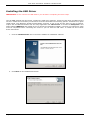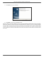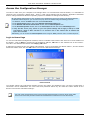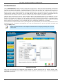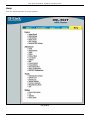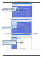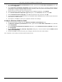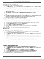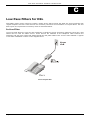
1
DSL-502T Generation II ADSL2+ Modem Router Page 1 of 91 www.dlink.com.au DSL-502T Generation II ADSL2+ Modem Router Table of Contents BEFORE YOU START.................................................................................... 4 Installation Overview......................................................................................................................... 4 Setup Wizard...................................................................................................................................... 4 Packing List........................................................................................................................................ 4 Installation Notes .............................................................................................................................. 5 Installing the USB Driver ................................................................................................................... 8 INTRODUCTION........................................................................................ 10 Router Description and Operation .................................................................................................... 10 Router Features ............................................................................................................................... 11 Front Panel Display .......................................................................................................................... 12 Rear Panel Connections ................................................................................................................... 13 HARDWARE INSTALLATION...................................................................... 14 Power on Router .............................................................................................................................. 14 Factory Reset Button........................................................................................................................ 14 Network Connections ....................................................................................................................... 15 BASIC ROUTER CONFIGURATION ............................................................. 16 Computer IP Settings ......................................................................................................................16 Access the Configuration Manager ................................................................................................... 17 Login to Home Page ........................................................................................................................17 Configure the Router........................................................................................................................ 18 Wizard ............................................................................................................................................. 19 WAN................................................................................................................................................. 27 PPPoE/PPPoA..................................................................................................................................27 Dynamic IP Address ........................................................................................................................30 Static IP Address ............................................................................................................................33 Bridge Mode...................................................................................................................................36 LAN .................................................................................................................................................. 40 DHCP................................................................................................................................................ 41 Using the Router for DHCP ...............................................................................................................42 Disabling the DHCP Server ...............................................................................................................42 DNS.................................................................................................................................................. 43 Dynamic DNS ................................................................................................................................... 44 Multiple Virtual Connections ............................................................................................................ 46 ADVANCED ROUTER MANAGEMENT .......................................................... 48 UPnP ................................................................................................................................................ 49 Virtual Server................................................................................................................................... 50 Custom Forwarding Rules.................................................................................................................52 LAN Clients....................................................................................................................................... 53 SNMP ............................................................................................................................................... 54 TR069 .............................................................................................................................................. 55 Filters............................................................................................................................................... 56 Bridge Filters ................................................................................................................................... 58 Page 2 of 91 www.dlink.com.au DSL-502T Generation II ADSL2+ Modem Router Static Routing .................................................................................................................................. 59 DMZ.................................................................................................................................................. 60 Parental Control ............................................................................................................................... 61 URL Blocking..................................................................................................................................62 Domain Blocking.............................................................................................................................62 Firewall ............................................................................................................................................ 63 RIP................................................................................................................................................... 64 ADSL ................................................................................................................................................ 65 ATM VCC........................................................................................................................................... 66 TOOLS ...................................................................................................... 67 Admin .............................................................................................................................................. 68 Change System Password ................................................................................................................68 Remote Web Management, Remote Telnet Access & Remote SSH Management........................................68 Time................................................................................................................................................. 69 Remote Log ...................................................................................................................................... 70 System ............................................................................................................................................. 71 Save or Load Configuration File.........................................................................................................71 Save Settings and Reboot System .....................................................................................................71 Restore Factory Default Settings .......................................................................................................71 Firmware.......................................................................................................................................... 72 Miscellaneous................................................................................................................................... 73 Ping Test .......................................................................................................................................73 IGMP Proxy....................................................................................................................................73 Test.................................................................................................................................................. 74 STATUS..................................................................................................... 75 Device Info ...................................................................................................................................... 75 DHCP Clients .................................................................................................................................... 76 Log................................................................................................................................................... 77 Statistics .......................................................................................................................................... 78 ADSL Status ..................................................................................................................................... 79 Help ................................................................................................................................................. 80 TECHNICAL SPECIFICATIONS................................................................... 81 CONFIGURING IP SETTINGS ON YOUR COMPUTER ................................... 83 LOW PASS FILTERS FOR DSL .................................................................... 89 Page 3 of 91 www.dlink.com.au DSL-502T Generation II ADSL2+ Modem Router About This User Guide This user’s guide provides instructions on how to install the DSL-502T ADSL Modem Router and use it to provide Internet access for an Ethernet network or single computer. If you are using a computer with a functioning Ethernet port, the quickest and easiest way to set up the DSL502T is to follow the instructions provided in the Quick Installation Guide (QIG). Before You Start Please read and make sure you understand all the prerequisites for proper installation of your new Router. Have all the necessary information and equipment on hand before beginning the installation. Installation Overview The procedure to install the Router can be described in general terms in the following steps: 1. Gather information and equipment needed to install the device. Before you begin the actual installation make sure you have all the necessary information and equipment. 2. Install the hardware, connect the cables to the device, and connect the power adapter. You will need to install a software driver to use the USB port. See the instructions below or go to the QIG for more details. 3. Check the IP settings on your computer and change them if necessary so the computer can access the web-based software built into the Router. 4. Use the web-based management software to configure the device to suit the requirements of your ADSL service and requirements of your local network. Setup Wizard Many users will be able to configure all the settings necessary to use the DSL-502T with the Setup Wizard. For ADSL connections that use PPPoE or PPPoA connections, the simplest way to set up the DSL-502T is to use the Setup Wizard to configure the Internet connection. Once you access the web interface used to configure the device, just launch the Setup Wizard to configure your Internet connection. If you are connecting a computer to the Router via the USB interface, you must first install the USB driver. Follow the installation instructions below to install the USB driver. Packing List Open the shipping carton and carefully remove all items. Make sure that you have the items listed here. • One DSL-502T GENERATION II ADSL Ethernet Modem Router • One CD-ROM containing User’s Guide, Quick Installation Guide, USB Drivers and D-Link Click’n Connect Utility • One twisted-pair telephone cable used for ADSL connection • One straight-through Ethernet cable • One USB cable • One AC power adapter suitable for your electrical service • One Quick Installation Guide Page 4 of 91 www.dlink.com.au DSL-502T Generation II ADSL2+ Modem Router Installation Notes In order to establish a connection to the Internet it will be necessary to provide information to the Router that will be stored in its memory. For some users, only their account information (Username and Password) is required. For others, various parameters that control and define the Internet connection will be required. You can print out the two pages below and use the tables to list this information. This way you have a hard copy of all the information needed to setup the Router. If it is necessary to reconfigure the device, all the necessary information can be easily accessed. Be sure to keep this information safe and private. Low Pass Filters Since ADSL and telephone services share the same copper wiring to carry their respective signals, a filtering mechanism may be necessary to avoid mutual interference. A low pass filter device can be installed for each telephone that shares the line with the ADSL line. These filters are easy to install passive devices that connect to the ADSL device and/or telephone using standard telephone cable. Ask your service provider for more information about the use of low pass filters with your installation. Operating Systems The DSL-502T uses a HTML-based web interface for setup and management. The web configuration manager may be accessed using any operating system capable of running web browser software, including Windows 98 SE, Windows ME, Windows 2000, and Windows XP. The D-Link Click’n Connect Utility will only work with a Windows operating system. Web Browser Most of common web browsers can be used to configure the Router using the web configuration management software. The program is designed to work best with more recently released browsers such as Microsoft Internet Explorer® version 6.0, Netscape Navigator® version 6.2.3, or later versions. The web browser must have JavaScript enabled. JavaScript is enabled by default on many browsers. Make sure JavaScript has not been disabled by other software (such as virus protection or web user security packages) that may be running on your computer. USB Port or Ethernet Port (NIC Adapter) Any computer that uses the Router must be able to connect to it through either the Ethernet port or USB port on the Router. The easiest method of installation is via the Ethernet connection and therefore requires that your computer be equipped with an Ethernet port as well. Most notebook computers are now sold with an Ethernet port already installed. Likewise, most fully assembled desktop computers come with an Ethernet NIC adapter as standard equipment. If your computer does not have an Ethernet port and you do not wish to use a USB connection, you must install an Ethernet NIC adapter before you can use the Router. If you must install an adapter, follow the installation instructions that come with the Ethernet NIC adapter. Additional Software For a bridged connection, the information needed to make and maintain the Internet connection is stored on another computer or gateway device using PPP client or similar third party client software, not in the Router itself. If your ADSL service is delivered through a PPPoE, PPPoA or Static IP connection, the information needed to establish and maintain the Internet connection can be stored in the Router. In this case, it is not necessary to install software on your computer. It may however be necessary to change some settings in the device, including account information used to identify and verify the connection. Note Page 5 of 91 If you plan to use the DSL-502T’s USB port to connect to your computer, do not connect the USB cable to the Router until you have finished all of the steps to install the USB driver, and your computer has restarted. www.dlink.com.au DSL-502T Generation II ADSL2+ Modem Router Information you will need from your ADSL service provider: Username This is the Username used to log on to your ADSL service provider’s network. It is commonly in the form − [email protected] Your ADSL service provider uses this to identify your account. Password This is the Password used, in conjunction with the Username above, to log on to your ADSL service provider’s network. This is used to verify the identity of your account. Record info here These settings describe the method your ADSL service provider uses to transport data between the Internet and your computer. Most users will use the default settings. You may need to specify one of the following WAN Setting and Connection Type configurations (Connection Type settings listed in parenthesis): PPPoE/PPoA (PPPoE LLC, PPPoA LLC or PPPoA VC-Mux) WAN Setting / Bridge Mode (1483 Bridged IP LLC or 1483 Bridged IP VC-Mux) Connection Type Static IP Address (Bridged IP LLC, 1483 Bridged IP VC-Mux, 1483 Routed IP LLC, 1483 Routed IP VC-Mux or IPoA) Dynamic IP Address (1483 Bridged IP LLC or 1483 Bridged IP VCMux) Default = PPPoE/PPPoA (PPPoE LLC) VPI Most users will not be required to change this setting. The Virtual Path Identifier (VPI) is used in conjunction with the Virtual Channel Identifier (VCI) to identify the data path between your ADSL service provider’s network and your computer. If you are setting up the Router for multiple virtual connections, you will need to configure the VPI and VCI as instructed by your ADSL service provider for the additional connections. This setting can be changed in the WAN Settings window of the web management interface. Default value = 8 VCI Most users will not be required to change this setting. The Virtual Channel Identifier (VCI) used in conjunction with the VPI to identify the data path between your ADSL service provider’s network and your computer. If you are setting up the Router for multiple virtual connections, you will need to configure the VPI and VCI as instructed by your ADSL service provider for the additional connections. This setting can be changed in the WAN Settings window of the web management interface. Default value = 35 The Setup Wizard can be used to configure the Internet connection for most users. Note Page 6 of 91 www.dlink.com.au DSL-502T Generation II ADSL2+ Modem Router Information you will need about your DSL-502T ADSL Modem Router: Username This is the Username needed access the Router’s management interface. When you attempt to connect to the device through a web browser you will be prompted to enter this Username. The default Username for the Router is “admin.” The user cannot change this. Password This is the Password you will be prompted to enter when you access the Router’s management interface. The default Password is “admin.” The user may change this. LAN IP addresses for the DSL-502T This is the IP address you will enter into the Address field of your web browser to access the Router’s configuration graphical user interface (GUI) using a web browser. The default IP address is 10.1.1.1. This may be changed to suit any IP address scheme the user desires. This address will be the base IP address used for DHCP service on the LAN when DHCP is enabled. LAN Subnet Mask for the DSL-502T This is the subnet mask used by the DSL-502T, and will be used throughout your LAN. The default subnet mask is 255.255.255.0. This can be changed later. Record info here Information you will need about your LAN or computer: Ethernet NIC If your computer has an Ethernet NIC, you can connect the DSL502T to this Ethernet port using an Ethernet cable. You can also use the Ethernet ports on the DSL-502T to connect to other computer or Ethernet devices. DHCP Client status Your DSL-502T ADSL Router is configured, by default, to be a DHCP server. This means that it can assign an IP address, subnet mask, and a default gateway address to computers on your LAN. The default range of IP addresses the DSL-502T will assign are from 10.1.1.2 to 10.1.1.254. Your computer (or computers) needs to be configured to Obtain an IP address automatically (that is, they need to be configured as DHCP clients.) Record info here It is recommended that your collect and record this information here, or in some other secure place, in case you have to re-configure your ADSL connection in the future. Once you have the above information, you are ready to setup and configure your DSL-502T ADSL Modem Router. Page 7 of 91 www.dlink.com.au DSL-502T Generation II ADSL2+ Modem Router Installing the USB Driver IMPORTANT: Do not connect the USB cable to your PC before completing the below steps. The CD-ROM shipped with the Router contains the USB driver software. Insert the DSL-502T CD-ROM into the CD drive. Within a few seconds you should see a window that offers the following options: Install Drivers, Quick Install Guide, View Manaual, Install Acrobat Reader, and Exit. If you do not see this auto-run pop-up window, explore the CD-ROM and double-click the setup application file autorun.exe or find the file Setup.exe in the folder labeled USBDriver and double-click it to launch the installation software. The auto-run USB driver setup must be completed before connecting the router to your PC with the USB cable. To install the driver follow these instructions: 1. Click the Install Drivers link to launch the USB driver installation software. 2. Click Next on the InstallShield window. Page 8 of 91 www.dlink.com.au DSL-502T Generation II ADSL2+ Modem Router 3. Click Install to begin the installation. 4. Click Finish to complete the InstallShield wizard. When the USB driver has been installed, insert one end of the USB cable included with the router into the DSL502T router’s USB port. Insert the other end of the USB cable into a USB port on your PC. Connect the power adapter to the power input at the back panel of the DSL-502T and then plug the other end of the power adapter to a wall outlet or power strip. On the front of the device, the Power LED will turn ON to indicate proper operation. Insert the telephone cable included with the Router into the ADSL port, and then connect the cable to your telephone line. Check the LED display on the front of the Router to confirm that the connections have been made. Page 9 of 91 www.dlink.com.au DSL-502T Generation II ADSL2+ Modem Router 1 Introduction This section provides a brief description of the Router, its associated technologies, and a list of Router features. Router Description and Operation The DSL-502T ADSL Modem Router is designed to provide a simple and cost-effective ADSL Internet connection for a private Ethernet network. The Router combines high-speed ADSL Internet connection, IP routing for the Local Area Network (LAN) connectivity in one package. The Router is easy to install and use. The DSL-502T connects to an Ethernet LAN or computers via standard Ethernet ports. The ADSL connection is made using ordinary telephone line with standard connectors. Multiple workstations can be networked and connected to the Internet using a single Wide Area Network (WAN) interface and single global IP address. The advanced security enhancements, packet filtering and port redirection, can help protect your network from potentially devastating intrusions by malicious agents from outside your network. ADSL Asymmetric Digital Subscriber Line (ADSL) is a broadband network technology that utilizes standard twistedpair copper wire telephone lines to enable broadband high-speed digital data transmission and bandwidth hungry applications for business and residential customers. ADSL2+ routers and modems provide faster downloads and more reliable connectivity to the user without loss of quality or disruption of voice/fax telephone capabilities. ADSL2+ provides a dedicated service over a single telephone line operating at speeds of up to 24Mbps downstream and up to 1Mbps upstream, depending on local telephone line conditions. A secure point-to-point connection is established between the user and the central office of the service provider. D-Link ADSL devices incorporate the recommendations of the ADSL Forum regarding framing, data format, and upper layer protocols. Page 10 of 91 www.dlink.com.au DSL-502T Generation II ADSL2+ Modem Router Router Features The DSL-502T ADSL Modem Router utilizes the latest ADSL enhancements to provide a reliable Internet portal suitable for most small to medium sized offices. DSL-502T advantages include: • PPP (Point-to-Point Protocol) Security – The DSL-502T ADSL Modem Router supports PAP (Password Authentication Protocol) and CHAP (Challenge Handshake Authentication Protocol) for PPP connections. • DHCP Support – Dynamic Host Configuration Protocol automatically and dynamically assigns all LAN IP settings to each host on your network. This eliminates the need to reconfigure every host whenever changes in network topology occur. • Network Address Translation (NAT) – For small office environments, the DSL-502T allows multiple users on the LAN to access the Internet concurrently through a single Internet account. This provides Internet access to everyone in the office for the price of a single user. NAT improves network security in effect by hiding the private network behind one global and visible IP address. NAT address mapping can also be used to link two IP domains via a LAN-to-LAN connection. • TCP/IP (Transfer Control Protocol/Internet Protocol) – The DSL-502T supports TCP/IP protocol, the language used for the Internet. It is compatible with access servers manufactured by major vendors. • RIP-1/RIP-2 – The DSL-502T supports both RIP-1 and RIP-2 exchanges with other routers. Using both versions lets the Router to communicate with all RIP enabled devices. • Static Routing – This allows you to select a data path to a particular network destination that will remain in the routing table and never “age out”. If you wish to define a specific route that will always be used for data traffic from your LAN to a specific destination within your LAN (for example to another router or a server) or outside your network (to an ISP defined default gateway for instance). • Default Routing – This allows you to choose a default path for incoming data packets for which the destination address is unknown. This is particularly useful when/if the Router functions as the sole connection to the Internet. • ATM (Asynchronous Transfer Mode) – The DSL-502T supports Bridged Ethernet over ATM (RFC1483), IP over ATM (RFC1577) and PPP over ATM (RFC 2364). • Precise ATM Traffic Shaping – Traffic shaping is a method of controlling the flow rate of ATM data cells. This function helps to establish the Quality of Service for ATM data transfer. • G.hs (Auto-handshake) – This allows the Router to automatically choose either the G.lite or G.dmt ADSL connection standards. • High Performance – Very high rates of data transfer are possible with the Router. Up to 24 Mbps downstream bit rate using the G.dmt.bisplus standard. • Full Network Management – The DSL-502T incorporates SNMP (Simple Network Management Protocol) support for web-based management and text-based network management via an RS-232 or Telnet connection. • Telnet Connection – The Telnet enables a network manager to access the Router’s management software remotely. • Easy Installation – The DSL-502T uses a web-based graphical user interface program for convenient management access and easy set up. Any common web browser software can be used to manage the Router. Page 11 of 91 www.dlink.com.au DSL-502T Generation II ADSL2+ Modem Router Front Panel Display Place the Router in a location that permits an easy view of the LED indicators on the front panel. The LED indicators on the front panel include Power, Status, ADSL, Ethernet, and USB. The ADSL, Ethernet, and USB indicators monitor link status and activity (Link/Act). Power Steady green light indicates the unit is powered on. When the device is powered off this remains dark. Status Lights steady green during power on self-test (POST). Once the connection status has been settled, the light will blink green. If the indicator lights steady green after the POST, the system has failed and the device should be rebooted. ADSL (Link/Act) Steady green light indicates a valid ADSL connection. This will light after the ADSL negotiation process has been settled. A blinking green light indicates activity on the WAN (ADSL) interface. Ethernet (Link/Act) A solid green light indicates a valid link on startup. This light will blink when there is activity currently on the Ethernet port. USB (Link/Act) Steady green light indicates a valid USB connection. A blinking green light indicates activity on the USB interface. Page 12 of 91 www.dlink.com.au DSL-502T Generation II ADSL2+ Modem Router Rear Panel Connections All cable connections to the Router are made at the rear panel. Connect the power adapter here to power on the Router. Use the Reset button to restore the settings to the factory default values in the next chapter for instructions on using the reset button). Connect network cables: 1. Insert the ADSL (telephone) cable included with the Router into the ADSL port and then connect the cable to your telephone line. 2. Insert one end of the Ethernet cable into the Ethernet (LAN) port on the back panel of the Router and the other end of the cable to an Ethernet Adapter or available Ethernet port on your computer. Power Jack Reset Button USB Port Connect USB cable here and install USB driver To manually reset, depress button with the power on for at least seven seconds Use the adapter shipped with the Router to connect to power source ADSL Port Ethernet Port Power Button Use the ADSL cable to connect to the your telephone line (RJ-11 port) Use the Ethernet port to connect the Router to your Ethernet LAN or computer Use the adapter shipped with the Router to connect to power source Page 13 of 91 www.dlink.com.au DSL-502T Generation II ADSL2+ Modem Router 2 Hardware Installation The DSL-502T maintains three separate interfaces, an ADSL, an Ethernet, and a USB interface. Place the Router in a location where it can be connected to the various devices as well as to a power source. The Router should not be located where it will be exposed to moisture or excessive heat. Make sure the cables and power cord are placed safely out of the way so they do not create a tripping hazard. As with any electrical appliance, observe common sense safety procedures. The Router can be placed on a shelf or desktop, ideally you should be able to see the LED indicators on the front if you need to view them for troubleshooting. Power on Router CAUTION: The Router must be used with the power adapter included with the device. To power on the Router: 1. Insert the AC Power Adapter cord into the power receptacle located on the rear panel of the Router and plug the adapter into a suitable nearby power source. 2. You should see the Power LED indicator light up and remain lit. The Status LED should light solid green and begin to blink after a few seconds. 3. If the Ethernet port is connected to a working device, check the Ethernet Link/Act LED indicators to make sure the connection is valid. The Router will attempt to establish the ADSL connection, if the ADSL line is connected and the Router is properly configured this should light up after several seconds. If this is the first time installing the device, some settings may need to be changed before the Router can establish a connection. Factory Reset Button The Router may be reset to the original factory default settings by depressing the reset button for a few seconds while the device is powered on. Use a ballpoint or paperclip to gently push down the reset button. Remember that this will wipe out any settings stored in flash memory including user account information and LAN IP settings. The device settings will be restored to the factory default IP address 10.1.1.1 and the subnet mask is 255.255.255.0, the default management Username is “admin” and the default Password is “admin.” Page 14 of 91 www.dlink.com.au DSL-502T Generation II ADSL2+ Modem Router Network Connections Network connections are provided through the ADSL port, the Ethernet port and the USB port on the back of the Router. See the Rear Panel diagram above and the illustrations below for examples. See Installing the USB Driver section above for a description of the USB driver installation procedure. Connect ADSL Line Use the ADSL cable included with the Router to connect it to a telephone wall socket or receptacle. Plug one end of the cable into the ADSL port (RJ-11 receptacle) on the rear panel of the Router and insert the other end into the RJ-11 wall socket. If you are using a low pass filter device, follow the instructions included with the device or given to you by your service provider. The ADSL connection represents the WAN interface, the connection to the Internet. It is the physical link to the service provider’s network backbone and ultimately to the Internet. Connect Router to Ethernet The Router may be connected to a single computer or Ethernet device through the 10/100 BASE-TX Ethernet port on the rear panel. Any connection to an Ethernet concentrating device such as a switch or hub must operate at a speed of 10/100 Mbps only. When connecting the Router to any Ethernet device that is capable of operating at speeds between 0~100Mbps, be sure that the device has auto-negotiation (NWay) enabled for the connecting port. Use Category 5 or better twisted-pair Ethernet cable with RJ-45 connectors. The RJ-45 port on the Router is auto MDI-X/MDI-II meaning that is will link correctly with either MDI-II through or MDI-X crossed ports. The rules governing Ethernet cable lengths apply to the LAN to Router connection. Be sure that the cable connecting the LAN to the Router does not exceed 100 meters. Page 15 of 91 www.dlink.com.au DSL-502T Generation II ADSL2+ Modem Router 3 Basic Router Configuration The first time you setup the Router it is recommended that you configure the WAN connection using a single computer connected directly to the Router. Once the WAN connection is functioning properly, you may continue to make changes to Router configuration including IP settings and DHCP setup. For information on how to configure advanced features such as port redirection, filtering and firewall, please skip ahead to the Advanced Router Management section. Configuration Summary 1. Connect to the Router To configure various settings used by the Router for Internet and access it is first necessary to access the Router’s management HTML-based interface. This is done using an ordinary web browser. Your computer must be able to “see” the Router before it can manage it using a browser. If the Router is in the same “neighborhood” or subnet as the Router, you should be able to access the management software. Therefore you must first make sure your computer has IP settings that place it in the same subnet as the Router. The easiest way to make sure your computer has the correct IP settings is to configure it to use the DHCP server in the Router. The DHCP server will automatically enable your computer to use a browser to manage the Router. The next section describes how to change the IP configuration for a computer running a Windows operating system to be a DHCP client. If you are running another operating system, make sure your computer is configured as a DHCP client so it can automatically obtain IP settings from the Router. Some operating systems will automatically select the best IP settings. Consult the user manual for the operating system (OS) if you are unsure. 2. Configure the Internet (WAN) Connection Most users will be able to complete this process using the Setup Wizard. The Setup Wizard can be launched once you have successfully connected with the Router’s management software. There are different methods used to establish the WAN connection to the service provider’s network and ultimately to the Internet. Your Router may already have most of the settings configured by default. However you will probably at least have to type in a user name and password given to you by your ISP. You may also need to know the encapsulation and connection type required to use for your ADSL service. Your service provider should provide all the information needed to configure the WAN connection. Computer IP Settings In order to configure your system to receive IP settings from the Router your computer must first have the TCP/IP protocol installed. If you have an Ethernet port on your computer, it probably already has TCP/IP protocol installed. If you are using Windows XP the TCP/IP is enabled by default for standard installations. Instructions for configuring your computer to receive IP settings from the Router are provided in Appendix B on page 84. For computers running non-Windows operating systems, follow the instructions for your OS that configure the system to receive an IP address from the Router, that is, configure the system to be a DHCP client. Note If you are not sure how to configure your Windows computer to be a DHCP client, see Configuring IP Settings on Your Computer beginning on page 84. Page 16 of 91 www.dlink.com.au DSL-502T Generation II ADSL2+ Modem Router Access the Configuration Manager In order to make sure your computer’s IP settings allow it to communicate with the Router, it is advisable to configure your system be a DHCP client – that is, it will get IP settings from the Router. Appendix B describes how to configure different Windows operating systems to “Obtain IP settings automatically”. Be sure that the web browser on your computer is not configured to use a proxy server in the Internet settings. In Windows Internet Explorer, you can check if a proxy server is enabled using the following procedure: 1. In Windows, click on the Start button and choose Control Panel. 2. In the Control Panel window, click on the Network and Internet Options icon. 3. In the Network and Internet Connections window, click the Internet Options icon. 4. In the Internet Properties window, click on the Connections tab and click on the LAN Settings button Note 5. Verify that the “Use a proxy server for your LAN (These settings will not apply to dial-up or VPN connections).” option is NOT checked. If it is checked, click in the checked box to deselect the option and click OK. Alternatively, you can access this Internet Options menu using the Tools pull-down menu in Internet Explorer. Login to Home Page To use the web-based management software, launch a suitable web browser and direct it to the IP address of the Router. Type in http:// followed by the default IP address, 10.1.1.1 in the address bar of the browser. The URL in the address bar should read: http://10.1.1.1. A dialog box prompts for the User Name and Password. Type in the default User Name “admin”, and the default Password “admin” then click the OK button to access the web-based manager. Enter Password You should change the web-based manager access user name and password once you have verified that a connection can be established. The user name and password allows any PC within the same subnet as the Router to access the web-based manger. Note The user name and password used to access the web-based manager is NOT the same as the ADSL account user name and password needed for PPPoE/PPPoA connections to access the Internet. Page 17 of 91 www.dlink.com.au DSL-502T Generation II ADSL2+ Modem Router Configure the Router When you successfully connect to the web manager, the Home directory tab will display the Setup Wizard window. You can launch the Setup Wizard from this page or use the buttons located in the left panel of the web page to view other windows used for basic configuration. Click on a directory tab to view the windows available in that directory Click on a button to use or view the window Click the Run Wizard button to launch the Setup Wizard Web Manager – First Time Log On All configuration and management of the Router is done using the web-based management interface pictured in the above example. The configuration windows are accessed by clicking on the directory tabs: Home, Advanced, Tools, Status, and Help. Each tab has associated window buttons in the left hand panel of the web interface. Basic setup of the Router can be completed in the windows accessed from the Home directory including: (Setup) Wizard, WAN (Internet), LAN (to configure the IP address of the Router) DHCP, DNS and Dynamic DNS. Page 18 of 91 www.dlink.com.au DSL-502T Generation II ADSL2+ Modem Router Wizard To use the Setup Wizard, click the Run Wizard button in the first browser window and follow the instructions in the pop-up window that appears. The initial window summarizes the setup process. Click the Next button to proceed. You may stop using the Setup Wizard at any time by clicking the Exit button. If you exit the wizard you will return to the Setup Wizard window without saving any of the settings changed during the process. The first pop-up window of the Setup Wizard lists the basic steps in the process. These steps are as follows: 1. Set the system time. 2. Configure the connection to the Internet. 3. Save the new configuration settings and reboot the system. Page 19 of 91 www.dlink.com.au DSL-502T Generation II ADSL2+ Modem Router Using the Setup Wizard - Choose Time Zone Choose the time zone you are in from the pull-down menu and click Next. This sets the system time used for the Router. If you wish to return to the previous window during the setup process, click the Back button. Page 20 of 91 www.dlink.com.au DSL-502T Generation II ADSL2+ Modem Router Using the Setup Wizard - Choose Connection Type Now select the Connection Type used for the Internet connection. Your ISP has given this information to you. The connection types available for “Multi-User” Mode are PPPoE/PPPoA, Dynamic IP Address, Static IP Address, and Bridge Mode. Each connection type has different settings that are configured in the next Setup Wizard pop-up window. Select the Connection Type specific to your service and click Next to go to the next Setup Wizard pop-up window. Follow the instructions below for the type of connection you have selected. Page 21 of 91 www.dlink.com.au DSL-502T Generation II ADSL2+ Modem Router Using the Setup Wizard - For PPPoE/PPPoA connections: 1. Type in the Username and Password used to identify and verify your account to the ISP. 2. Select the specific Connection Type from the drop-down menu. The available PPP connection and encapsulation types are PPPoE LLC, PPPoA LLC and PPPoA VC-Mux. 3. If you are instructed to change the VPI or VCI number, type in the correct setting in the available entry fields. Most users will not need to change these settings. The Internet connection cannot function if these values are incorrect. 4. Click Next to go to the next window and complete the Setup Wizard. Page 22 of 91 www.dlink.com.au DSL-502T Generation II ADSL2+ Modem Router Using the Setup Wizard - For Dynamic IP Address connections: 1. Select the specific Connection Type from the drop-down menu. The available Dynamic IP Address connection and encapsulation types are 1483 Bridged IP LLC and 1483 Bridged IP VC-Mux. 2. If you are instructed to change the VPI or VCI number, type in the correct setting in the available entry fields. Most users will not need to change these settings. The Internet connection cannot function if these values are incorrect. 3. You may want to copy the MAC address of your Ethernet adapter to the Router. Some ISPs record the unique MAC address of your computer’s Ethernet adapter when you first access their network. This can prevent the Router (which has a different MAC address) from being allowed access to the ISPs network (and the Internet). To clone the MAC address of your computer’s Ethernet adapter, type in the MAC address in the Cloned MAC Address field and click the Clone MAC Address button. This will copy the information to a file used by the Router to present to the ISP’s server used for DHCP. 4. Click Next to go to the next pop-up window and complete the Setup Wizard. Page 23 of 91 www.dlink.com.au DSL-502T Generation II ADSL2+ Modem Router Using the Setup Wizard - For Static IP Address connections: 1. Select the specific Connection Type from the drop-down menu. The available Static IP Address connection and encapsulation types are 1483 Bridged IP LLC, 1483 Bridged IP VC-Mux, 1483 Routed IP LLC, 1483 Routed IP VC-Mux and IPoA. 2. Change the IP Address, Subnet Mask, ISP Gateway Address, Primary DNS Address, and Secondary DNS Server IP Address as instructed by your ISP. For IPoA connections it may also be necessary to change the ARP Server Address. IPoA connection users who have not been given this information should leave the field blank. 3. If you are instructed to change the VPI or VCI number, type in the correct setting in the available entry fields. Most users will not need to change these settings. The Internet connection cannot function if these values are incorrect. 4. Click Next to go to the next window and complete the Setup Wizard. Page 24 of 91 www.dlink.com.au DSL-502T Generation II ADSL2+ Modem Router Using the Setup Wizard - For Bridge Mode connections: 1. Select the specific Connection Type from the drop-down menu. The available Bridge Mode connection and encapsulation types are 1483 Bridged IP LLC and 1483 Bridged IP VC-Mux. 2. If you are instructed to change the VPI or VCI number, type in the correct setting in the available entry fields. Most users will not need to change these settings. The Internet connection cannot function if these values are incorrect. 3. Click Next to go to the next window and complete the Setup Wizard. Page 25 of 91 www.dlink.com.au DSL-502T Generation II ADSL2+ Modem Router Using the Setup Wizard - Finish and Restart Finally you can confirm that the setup process is completed. If you are satisfied that you have entered all the necessary information correctly, click the Restart button to save the new configuration settings and restart the Router. If you need to change settings from a previous window, click the Back button. Do not turn the Router off while it is restarting. After the Router is finished restarting, you are now ready to continue to configure the Router as desired. You may want to test the WAN connection by accessing the Internet with your browser. Page 26 of 91 www.dlink.com.au DSL-502T Generation II ADSL2+ Modem Router WAN To configure the Router’s basic configuration settings without running the Setup Wizard, you can access the windows used to configure WAN, LAN, DHCP, and DNS settings directly from the Home directory. To access the WAN Settings window, click on the WAN link button on the left side of the first window that appears when you successfully access the web manager. PPPoE/PPPoA Follow the instructions below to configure the Router to use a PPPoE or PPPoA for the Internet connection. Make sure you have all the necessary information before you configure the WAN connection. WAN Settings window – PPPoE/PPPoA Page 27 of 91 www.dlink.com.au DSL-502T Generation II ADSL2+ Modem Router To configure a PPPoE or PPPoA type WAN connection, follow these steps: 1. If not already selected, choose the PPPoE/PPPoA option from the WAN Settings pull-down menu. PPPoE/PPPoA is selected by default if you are configuring the Router for the first time. 2. Under the ATM VC Settings at the top of the window should not be changed unless you have been instructed to change them. However, if you are instructed to change the VPI or VCI values, type in the values assigned for your account. Leave the PVC and Virtual Circuit setting at the default (Pcv0 and Enabled) values for now. This can be used later if you are configuring multiple virtual circuits for your ADSL service. For more information on ATM VC Settings, see the table on below page. 3. Under the PPPoE/PPPoA heading, type the User Name and Password used for your ADSL account. A typical User Name will be in the form [email protected]. The Password may be assigned to you by your ISP or you may have selected it when you set up the account with your ISP. 4. Choose the Connection Type from the pull-down menu located under the User Name and Password entry fields. This defines both the connection protocol and encapsulation method used for your ADSL service. The available options are PPPoA VC-Mux, PPPoA LLC and PPPoE LLC. If have not been provided specific information for the Connection Type setting, leave the default setting. 5. Leave the MTU value at the default setting (default = 1400) unless you have specific reasons to change this (see table below). 6. Leave the MRU value at the default setting (default = 1492) unless you have specific reasons to change this (see table below). 7. Leave the Default Route enabled if you want to use the Router as the default route to the Internet for your LAN. Whenever a computer on the LAN attempts to access the Internet, the Router becomes the Internet gateway to the computer. If you have an alternative route for Internet traffic you may disable this without effecting the Router’s connection. 8. NAT should remain Enabled. If you disable NAT, you will not be able to use more than one computer for Internet connections. NAT is enabled and disabled system-wide, therefore if you are using multiple virtual connections, NAT will disabled on all connections. 9. The Firewall should remain enabled for most users. If you choose to disable this you will not be able to use the features configured in the Firewall Configuration and Filters windows located in the Advanced directory. See the next chapter for more details on these windows. 10. Typically the globally IP settings (i.e. IP address for the WAN interface) for a PPPoA or PPPoA connection will use Dynamic IP assignment from the ISP. Some accounts may be assigned a specific global IP address. If you have been give an IP address for you PPPoE/PPPoA connection, select the Static IP option from the IP Control pull-down menu. This menu can be used to configure the WAN port as an Unnumbered IP interface. (See table below for Unnumbered IP) 11. Most users will not need to change ATM settings. If this is the first time you are setting up the ADSL connection it is recommended that you leave the Service Category settings at the default values until you have established the connection. See the table for a description of the parameters available for ATM traffic shaping. 12. When you are satisfied that all the WAN settings are configured correctly, click on the Apply button. 13. The new settings must be saved and the Router must be restarted for the settings to go into effect. To save and reboot the Router, click on the Tools directory tab and then click the System button. In the System Settings window, click the Save and Reboot button under Save Settings and Reboot the System. 14. Click OK when the following “Save and restart?” dialog box opens. 15. The Router will save the new settings and restart. Upon restarting the Router will automatically establish the WAN connection. Page 28 of 91 www.dlink.com.au DSL-502T Generation II ADSL2+ Modem Router Additional settings for PPPoE/PPPoA connections: PPPoE/PPPoA Parameters Description User Name For PPP connections, a User Name and Password are used to identify and verify your account to the ISP. Enter the User Name for your ADSL service account. User names and passwords are case-sensitive, so enter this information exactly as given to you by your ISP. Password Together with the User Name, this is used to verify your account to the ISP. Enter the Password exactly as given to you by your ISP. Connection Type This specifies the protocol (PPPoE or PPPoA) and the encapsulation method (LLC or VCMux) used for your connection. The options available are PPPoE LLC, PPPoA LLC or PPPoA VC-Mux. MTU The Maximum Transmission Unit size may be changed if you want to optimize efficiency for uploading data through the WAN interface. The default setting (1400 bytes) should be suitable for most users. Some user may want to adjust the setting to optimize performance for wireless traffic or when low latency is desired (such as with Internet gaming). It is highly recommended that the user research how adjusting the MTU may effect network traffic for better or worse. MRU Similar to the MTU, except this applies to Maximum Received Unit size for downloading data. Most users will be happy with the default setting (1492 bytes). However this may also be optimized for fast downloads of general bulk Internet traffic, for low latency or for downloading to computers on the Wireless LAN. As with the MTU setting, the user should carefully consider how changing the MRU may affect Internet downloads for all systems on your LAN. Default Route When this is enabled, the Router will be considered to be the primary gateway to the Internet and WAN for systems on your network. If you are using the Router on a network with one or more alternative gateway routers, you may prefer to disable this if you will use another router as the primary gateway. PPPoE PassThrough This feature enables the Router to allow a “dial-up” or separate bridged PPP connection to an individual PC. In this instance the Router will serve as a bridge. NAT Network Address Translation may be enabled or disabled with the pull-down menu. Keep in mind that disabling NAT allows only a single computer to be used for Internet access through the Router. NAT is enabled and disabled for the Router on all connections (i.e. Pvc0 – Pvc7) if your Router is set up for multiple virtual connections. Firewall Use this to universally enable or disable the Firewall and Filter features available in the Router. If you disable this you will not be able to configure settings in the Firewall Configuration window or Filters window in the Advanced directory. IP Control This is used to determine how global IP settings are handled for the WAN interface. Typically PPPoE or PPPoA connections will use the default setting for Dynamic IP. Some users will be given a specific IP address for the WAN interface. In this case you need to change this setting to Static IP. When Static IP is selected in the IP Control menu, you need to type in the global IP address provided to you by your ISP. The IP Unnumbered option is used if you want to set up a non-TCP/IP port protocol link through the WAN interface. An IP Unnumbered interface does not have an IP address and therefore cannot be managed via Telnet or any other TCP/IP application. Static IP If you have selected the Static IP option in the IP Control menu, type in the global IP address used for your WAN interface. Your ISP should provide this IP address to you. Connection Setting Select the desired option: Always ON, Connection On Demand, or Manual. Most users will want to choose the default connection setting, Always ON. Page 29 of 91 www.dlink.com.au DSL-502T Generation II ADSL2+ Modem Router Dynamic IP Address A Dynamic IP Address connection configures the Router to automatically obtain its global IP address from a DHCP server on the ISP’s network. The service provider assigns a global IP address from a pool of addresses available to the service provider. Typically the IP address assigned has a long lease time, so it will likely be the same address each time the Router requests an IP address. To configure a Dynamic IP Address connection, perform the steps listed below. Some of the settings do not need to be changed the first time the device is set up, but can be changed later if you choose. See the table below for a description of all the settings available in this window. WAN Settings window – Dynamic IP Address Page 30 of 91 www.dlink.com.au DSL-502T Generation II ADSL2+ Modem Router To configure a Dynamic IP Address connection for the WAN, follow these steps: 1. Choose the Dynamic IP Address option from the WAN Settings pull-down menu. 2. Under the ATM VC Settings at the top of the window should not be changed unless you have been instructed to change them. However, if you are instructed to change the VPI or VCI values, type in the values assigned for your account. Leave the PVC and Virtual Circuit setting at the default (Pcv0 and Enabled) values for now. This can be used later if you are configuring multiple virtual circuits for your ADSL service. For more information on ATM VC Settings, see the table on the below page. 3. Under the Dynamic IP heading, choose the Connection Type from the pull-down menu. This defines both the connection type and encapsulation method used for your ADSL service. The available options are 1483 Bridged IP LLC and 1483 Bridged IP VC-Mux. If have not been provided specific information for the Connection Type setting, leave the default setting. 4. Some ISPs record the unique MAC address of your computer’s Ethernet adapter when you first access their network. This can prevent the Router (which has a different MAC address) from being allowed access to the ISPs network (and the Internet). To clone the MAC address of your computer’s Ethernet adapter, type in the MAC address in the Cloned MAC Address field and click the Clone MAC Address button. 5. Leave the MTU value at the default setting (default = 1400) unless you have specific reasons to change this (see table below). 6. NAT should remain Enabled. If you disable NAT, you will not be able to use more than one computer for Internet connections. NAT is enabled and disabled system-wide, therefore if you are using multiple virtual connections, NAT will disabled on all connections. 7. The Firewall should remain enabled for most users. If you choose to disable this you will not be able to use the features configured in the Firewall Configuration and Filters windows located in the Advanced directory. See the next chapter for more details on these windows. 8. Most users will not need to change ATM settings. If this is the first time you are setting up the ADSL connection it is recommended that you leave the Service Category settings at the default values until you have established the connection. See the table on page Error! Bookmark not defined. for a description of the parameters available for ATM traffic shaping. 9. When you are satisfied that all the WAN settings are configured correctly, click on the Apply button. 10. The new settings must be saved and the Router must be restarted for the settings to go into effect. To save and reboot the Router, click on the Tools directory tab and then click the System button. In the System Settings window, click the Save and Reboot button under Save Settings and Reboot the System. 11. Click OK when the following “Save and restart?” dialog box opens. 12. The Router will save the new settings and restart. Upon restarting the Router will automatically establish the WAN connection. Page 31 of 91 www.dlink.com.au DSL-502T Generation II ADSL2+ Modem Router Additional settings for Dynamic IP Address connections: Dynamic IP Parameters Description Connection Type This specifies the connection type and encapsulation method used for your Dynamic IP Address connection. The options available are Bridged IP LLC or Bridged IP VC-Mux. Clone MAC Address This is not always necessary, but may be required for some ISPs. Type in the MAC address of your computer’s Ethernet adapter in the Cloned MAC Address field and click the Clone MAC Address button. This will copy the information to a file used by the Router to present to the ISP’s server used for DHCP. Some ISPs record the unique MAC address of your computer’s Ethernet adapter when you first access their network. If you want to later replace the cloned MAC address with the factory default setting, type in all zeros 00:00:00:00:00:00 - and click the Clone MAC Address button. Clone MAC Address To clone the MAC address of your computer’s Ethernet adapter, type in the MAC address in the Cloned MAC Address field and then click this Clone MAC Address button. MTU The Maximum Transmission Unit size may be changed if you want to optimize efficiency for uploading data through the WAN interface. The default setting (1400 bytes) should be suitable for most users. Some user may want to adjust the setting to optimize performance for wireless traffic or when low latency is desired (such as with Internet gaming). It is highly recommended that the user research how adjusting the MTU may affect network traffic for better or worse. NAT Network Address Translation may be enabled or disabled with the pull-down menu. Keep in mind that disabling NAT allows only a single computer to be used for Internet access through the Router. NAT is enabled and disabled for the Router on all connections (i.e. Pvc0 – Pvc7) if your Router is set up for multiple virtual connections. Firewall Use this to universally enable or disable the Firewall and Filter features available in the Router. If you disable this you will not be able to configure settings in the Firewall Configuration window or Filters windows in the Advanced directory. Page 32 of 91 www.dlink.com.au DSL-502T Generation II ADSL2+ Modem Router Static IP Address When the Router is configured to use Static IP Address assignment for the WAN connection, you must manually assign a global IP Address, Subnet Mask and Gateway IP Address used for the WAN connection. Most users will also need to configure DNS server IP settings in the DNS Configuration window (see below). Follow the instruction below to configure the Router to use Static IP Address assignment for the WAN connection. To configure a Static IP Address connection, perform the steps listed below. Some of the settings do not need to be changed the first time the device is set up, but can be changed later if you choose. See the table below for a description of all the settings available in this window. WAN Settings window - Static IP Page 33 of 91 www.dlink.com.au DSL-502T Generation II ADSL2+ Modem Router To configure a Static IP type connection for the WAN, follow these steps: 1. Choose the Static IP Address option from the WAN Settings pull-down menu. 2. Under the ATM VC Settings at the top of the window should not be changed unless you have been instructed to change them. However, if you are instructed to change the VPI or VCI values, type in the values assigned for your account. Leave the PVC and Virtual Circuit setting at the default (Pcv0 and Enabled) values for now. This can be used later if you are configuring multiple virtual circuits for your ADSL service. For more information on ATM VC Settings, see the table on below page. 3. Under the Static IP heading, choose the Connection Type from the pull-down menu. This defines both the connection type and encapsulation method used for your ADSL service. The available options are Bridged IP LLC, Bridged IP VC-Mux, Routed IP LLC, Routed IP VC-Mux or IPoA. If have not been provided specific information for the Connection Type setting, leave the default setting. 4. Change the IP Address, Subnet Mask, Gateway Address and (if available) Secondary DNS Server IP address as instructed by your ISP. These are the global IP settings for the WAN interface. This is the “visible” IP address of your account. Your ISP should have provided these IP settings to you. For IPoA (Classic IP over ATM) connections you may need to type in an additional IP address for a ARP Server Address. If you are using an IPoA connection, ask your ISP if it is necessary to use an ARP (Address Resolution Protocol) server. 5. Leave the MTU value at the default setting (default = 1400) unless you have specific reasons to change this (see table below). 6. NAT should remain Enabled. If you disable NAT, you will not be able to use more than one computer for Internet connections. NAT is enabled and disabled system-wide, therefore if you are using multiple virtual connections, NAT will be disabled on all connections. 7. The Firewall should remain enabled for most users. If you choose to disable this you will not be able to use the features configured in the Firewall Configuration and Filters window located in the Advanced directory. See the next chapter for more details on these windows. 8. Most users will not need to change ATM settings. If this is the first time you are setting up the ADSL connection it is recommended that you leave the Service Category settings at the default values until you have established the connection. See the table on below for a description of the parameters available for ATM traffic shaping. 9. When you are satisfied that all the WAN settings are configured correctly, click on the Apply button. 10. The new settings must be saved and the Router must be restarted for the settings to go into effect. To save and reboot the Router, click on the Tools directory tab and then click the System button. In the System Settings window, click the Save and Reboot button under Save Settings and Reboot the System. 11. Click OK when the following “Save and restart?” dialog box opens. 12. The Router will save the new settings and restart. Upon restarting the Router will automatically establish the WAN connection. Page 34 of 91 www.dlink.com.au DSL-502T Generation II ADSL2+ Modem Router Additional settings for Static IP Address connections: Static IP Parameters Description Connection Type This specifies the connection type and the encapsulation method used for your Static IP Address connection. The options available are Bridged IP LLC, Bridged IP VC-Mux, Routed IP LLC, Routed IP VC-Mux or IPoA. IP Address This is the permanent global IP address for your account. This is the address that is visible outside your private network. Get this from your ISP. Subnet Mask This is the Subnet mask for the WAN interface. Get this from your ISP. Gateway Address This is the IP address of your ISP’s Gateway router. It provides the connection to the Router for IP routed traffic that is outside your ISP’s network. That is, this will be the primary connection from the Router to most of the Internet. Get this IP address from your ISP. ARP Server Address This is not required for all IPoA connections. Check with your ISP for an ARP server IP address if this is necessary for your IPoA connection. (IPoA connection only) Primary DNS Address This is the IP address of the first choice for Domain Name Service (DNS) used to match the named URL web address used by most browsers with the actual global IP address used for a web server. Usually this will be a server owned by the ISP. Get this IP address from your ISP. Secondary DNS Address This is the second choice for a DNS server. Get this IP address from your ISP. MTU The Maximum Transmission Unit size may be changed if you want to optimize efficiency for uploading data through the WAN interface. The default setting (1400 bytes) should be suitable for most users. Some user may want to adjust the setting to optimize performance for wireless traffic or when low latency is desired (such as with Internet gaming). It is highly recommended that the user research how adjusting the MTU may affect network traffic for better or worse. NAT Network Address Translation may be enabled or disabled with the pull-down menu. Keep in mind that disabling NAT allows on a single computer to be used for Internet access through the Router. NAT is enabled and disabled for the Router on all connections (i.e. Pvc0 – Pvc7) if your Router is set up for multiple virtual connections. Firewall Use this to universally enable or disable the Firewall and Filter features available in the Router. If you disable this you will not be able to configure settings in the Firewall Configuration window or the Filters window in the Advanced directory. Page 35 of 91 www.dlink.com.au DSL-502T Generation II ADSL2+ Modem Router Bridge Mode The WAN Settings window is also used to configure the Router for multiple virtual connections (Multiple PVCs). WAN Settings window – Bridge Mode Select the connection type used for your account. The window will display settings that are appropriate for the connection type you select. Follow the instruction below according to the type of connection you select in the WAN Settings window. For Bridged connections it will be necessary for most users to install additional software on any computer that will the Router for Internet access. The additional software is used for the purpose of identifying and verifying your account, and then granting Internet access to the computer requesting the connection. The connection software requires the user to enter the User Name and Password for the ISP account. This information is stored on the computer, not in the Router. Page 36 of 91 www.dlink.com.au DSL-502T Generation II ADSL2+ Modem Router Follow the instructions below to configure a Bridged connection for the WAN interface. To configure a Dynamic IP Address connection, perform the steps listed below. Some of the settings do not need to be changed the first time the device is set up, but can be changed later if you choose. See the table below for a description of all the settings available in this window. 1. Choose the Bridge Mode option from the WAN Settings pull-down menu. 2. Under the ATM VC Settings at the top of the window should not be changed unless you have been instructed to change them. However, if you are instructed to change the VPI or VCI values, type in the values assigned for your account. Leave the PVC and Virtual Circuit setting at the default (Pcv0 and Enabled) values for now. This can be used later if you are configuring multiple virtual circuits for your ADSL service. For more information on ATM VC Settings, see the table on below page. 3. Under the Bridge Mode heading, choose the Connection Type from the pull-down menu. This defines both the connection type and encapsulation method used for your ADSL service. The available options are 1483 Bridged IP LLC and 1483 Bridged IP VC-Mux. If have not been provided specific information for the Connection Type setting, leave the default setting. 4. Most users will not need to change ATM settings. If this is the first time you are setting up the ADSL connection it is recommended that you leave the Service Category settings at the default values until you have established the connection. See the table on the below page for a description of the parameters available for ATM traffic shaping. 5. When you are satisfied that all the WAN settings are configured correctly, click on the Apply button. 6. The new settings must be saved and the Router must be restarted for the settings to go into effect. To save and reboot the Router, click on the Tools directory tab and then click the System button. In the System Settings window, click the Save and Reboot button under Save Settings and Reboot the System. 7. Click OK when the following “Save and restart?” dialog box opens. 8. The Router will save the new settings and restart. Upon restarting the Router will automatically establish the WAN connection. Page 37 of 91 www.dlink.com.au DSL-502T Generation II ADSL2+ Modem Router ATM Traffic Shaping The ATM settings in the WAN Settings windows for the different connection types can be used to adjust QoS parameters for ADSL clients. This may not be available to all ADSL accounts. ATM Settings for WAN connection Additional ATM settings for PPPoE or PPPoA connections: ATM Parameters Description The ATM settings allow the user to adjust ATM Quality of Service (QoS) or traffic parameters to suit specific traffic requirements. For applications or circumstances where packet loss or packet delay is a concern, ATM QoS can be adjusted to minimize problems. For most accounts, it will not be necessary to change these settings. Altering QoS settings can adversely affect performance of some commonly used Internet applications. If you plan to change QoS or traffic parameters, contact your ISP or network services provider for information on what types of adjustment are available or possible for your account. Your ISP may not support the class of service you want to use. To adjust ATM QoS parameters, select one of the Service Categories listed here and type in the PCR value in the entry field below. For the VBR service category, an additional parameter (SCR) must also be defined. Service Category UBR – Unspecified Bit Rate, this is the default category used for general-purpose Internet traffic where normal levels of packet loss and delay are acceptable. For some applications or for multiple connection accounts, it may be desirable to specify the PCR. CBR – Constant Bit Rate, usually used in circumstances where very low packet loss and very low Cell Delay Variable (CDV) are desirable. VBR-nt – Real-time Variable Bit Rate. This models bursty traffic with specified peak and sustainable rates. Please note that when VBR-rt is specified, both PCR and SCR are required (by ATM standards). VBR-nrt – Non-real-time Variable Bit Rate, usually used when network traffic is characterized by bursts of packets at variable intervals, and some moderate packet loss and delay is acceptable. This category is typically used for audio and video applications such as teleconferencing. The network must support QoS Class 2 to use VBR-nrt. PCR Peak Cell Rate – The PCR is inversely related to the time interval between ATM cells. It is specified for all three service categories (UBR, CBR and VBR) in Kbps. SCR Sustainable Cell Rate – The SCR is defined for the VBR service category. This is the rate that can be sustained for “bursty”, on-off traffic sources. It is a function of Maximum Burst Size (MBS) and the time interval (between cells). Page 38 of 91 www.dlink.com.au DSL-502T Generation II ADSL2+ Modem Router ATM VC Settings ATM VC settings can be configured for all connection types in the WAN configuration menu of the Home directory. ATM VC Settings in WAN Settings window The table below describes the ATM VC settings used to configure a PPPoE or PPPoA connection for an ADSL account. ATM VC Parameters Description PVC The Router supports using up to eight multiple virtual connections. This window allows the user to configure WAN settings for all the available connections (see instructions below on how to set up Multiple Virtual Connections). Use the PVC drop-down menu to select the connection (Pvc0 to Pvc7) you want to configure. Since most users will use only a single connection, the default setting Pvc0 can be used for any changes made to the WAN settings. VPI The Virtual Path Identifier is used with the VCI to define a dedicated circuit on the ATM network portion of the connection to the Internet and WAN. Most users will not need to change this setting. VCI The Virtual Channel Identifier is used with the VPI to define a dedicated circuit on the ATM network portion of the connection to the Internet and WAN. Most users will not need to change this setting. Virtual Circuit As with the PVC setting, this is mainly for use by clients who are configuring the Router for multiple virtual connections. Use this to enable or disable the PVC you are currently configuring. By default, the Pvc0 is Enabled and the remaining PVCs are disabled. Page 39 of 91 www.dlink.com.au DSL-502T Generation II ADSL2+ Modem Router LAN You can configure the LAN IP address to suit your preference. Many users will find it convenient to use the default settings together with DHCP service to manage the IP settings for their private network. The IP address of the Router is the base address used for DHCP. In order to use the Router for DHCP on your LAN, the IP address pool used for DHCP must be compatible with the IP address of the Router. The IP addresses available in the DHCP IP address pool will change automatically if you change the IP address of the Router. See the next section for information on DHCP setup. To access the Management IP window, click the LAN button in the Home directory. Management IP window To change the LAN IP Address or Subnet Mask, type in the desired values and click the Apply button. Your web browser should automatically be redirected to the new IP address. You will asked to login again to the Router’s web manager. Page 40 of 91 www.dlink.com.au DSL-502T Generation II ADSL2+ Modem Router DHCP The DHCP server is enabled by default for the Router’s Ethernet LAN interface. DHCP service will supply IP settings to workstations configured to automatically obtain IP settings that are connected to the Router though the Ethernet port. When the Router is used for DHCP it becomes the default gateway for DHCP client connected to it. Keep in mind that if you change the IP address of the Router the range of IP addresses in the pool used for DHCP on the LAN will also be changed. The IP address pool can be up to 253 IP addresses. DHCP Settings window To display the DHCP Settings window, click the DHCP button in the Home directory. Any active DHCP Clients appear at the bottom of the window in the DHCP Clients List. The IP address and MAC address for active DHCP clients are displayed in the list. The two options for DHCP service are as follows: You may use the Router as a DHCP server for your LAN. You can disable DHCP service and manually configure IP settings for workstations. You may also configure DNS settings for the LAN when using the Router in DHCP mode. In Auto DNS Mode, the Router will automatically relay DNS settings to properly configured DHCP clients. To manually enter DNS IP addresses, select the Manual DNS Mode option and type in a Primary and Secondary DNS IP Address in the field provided. The manually configured DNS settings will be supplied to clients that are configured to request them from the Router. Follow the instructions below according to which of the above DHCP options you want to use. When you have configured the DHCP Settings as you want them, click the Apply button to commit the new settings. Page 41 of 91 www.dlink.com.au DSL-502T Generation II ADSL2+ Modem Router Using the Router for DHCP To use the built-in DHCP server, click to select the DHCP Server option if it is not already selected. The IP Address Pool settings can be adjusted. The Starting IP Address is the lowest available IP address (default = 10.1.1.2). If you change the IP address of the Router this will change automatically to be 1 more that the IP address of the Router. The Ending IP Address is the highest IP address number in the pool. Type in the Lease Time in the entry field provided. This is the amount of time in seconds that a workstation is allowed to reserve an IP address in the pool if the workstation is disconnected from the network or powered off. Disabling the DHCP Server To disable DHCP, click to select the No DHCP option and click on the Apply button. Choosing this option requires that workstations on the local network must be configured manually or use another DHCP server to obtain IP settings. If you configure IP settings manually, make sure to use IP addresses in the subnet of the Router. You will need to use the Router’s IP address as the Default Gateway for the workstation in order to provide Internet access. DHCP Settings window with DHCP disabled Note To manually configure IP settings on Windows workstations, open the TCP/IP Properties menu and select the “Use the following IP address” option. You will need to supply the IP addres, Subnet mask and Defualt gateway (use IP address of DSL-502T) for each workstation. The example here also uses manually configured DNS settings. Static IP on LAN If the Router has the DHCP server enabled it is possible to permanently assign IP addresses to workstations specified by their MAC address. Up to five IP addresses may be assigned to five different devices. This will take the chosen IP address used out of the available addresses in the dynamic IP address pool and give a permanent lease time for the IP address to the selected device. To assign an IP address that will not age out, type in the MAC Address of the device and its static IP Address in the spaces provided. Use the format: 00-00-00-00-00-00 for the MAC address and the standard format: 10.1.1.xxx for the IP address. A Static DHCP Client List will appear below the DHCP Client list with any clients that have been configured for static IP address assignment. Page 42 of 91 www.dlink.com.au DSL-502T Generation II ADSL2+ Modem Router DNS The Router can be configured to relay DNS settings from your ISP or another available service to workstations on your LAN. When using DNS relay, the Router will accept DNS requests from hosts on the LAN and forward them to the ISP’s, or alternative DNS servers. DNS relay can use auto discovery or the DNS IP address can be manually entered by the user. Alternatively, you may also disable the DNS relay and configure hosts on your LAN to use DNS servers directly. Most users who are using the Router for DHCP service on the LAN and are using DNS servers on the ISP’s network, will leave DNS relay enabled (either auto discovery or user configured). DNS Configuration window In the DNS Relay Selection pull-down menu, choose to Use Auto Discovered DNS Server Only, Use User Discovered DNS ServerOnly or Disable DNS Relay. If you have not been given specific DNS server IP addresses or if the Router is not pre-configured with DNS server information, select the Use Auto Discovered DNS ServerOnly option. Auto discovery DNS instructs the Router to automatically obtain the DNS IP address from the ISP through DHCP. If your WAN connection uses a Static IP address, auto discovery for DNS cannot be used. If you have DNS IP addresses provided by your ISP, enter these IP addresses in the available entry fields for the Preferred DNS Server and the Alternative DNS Server. If you choose to Disable DNS Relay, it will be necessary to configure DNS settings for hosts on the LAN since they will not be depending on the Router to forward the DNS requests. When you have configured the DNS settings as desired, click the Apply button. Note To use DNS Relay for computers on your local network, DNS Service Filtering must be disabled. See the Firewall section in the next chapter. Page 43 of 91 www.dlink.com.au DSL-502T Generation II ADSL2+ Modem Router Dynamic DNS The Router supports DDNS (Dynamic Domain Name Service). The Dynamic DNS service allows a dynamic public IP address to be associated with a static host name in any of the many domains, allowing access to a specified host from various locations on the Internet. This is enabled to allow remote access to a host by clicking a hyperlinked URL in the form hostname.dyndns.org, Many ISPs assign public IP addresses using DHCP, this can make it difficult to locate a specific host on the LAN using standard DNS. If for example you are running a public web server or VPN server on your LAN, this ensures that the host can be located from the Internet if the public IP address changes. DDNS requires that an account be setup with one of the supported DDNS providers. Dynamic DNS Configuration window Note: DDNS requires that an account be setup with one of the supported DDNS servers prior to engaging it on the router. This function will not work without an accepted account with a DDNS server. Enter the required DDNS information and click Apply to set this information in the Router. DDNS Parameters Description DDNS Server Select one of the DDNS registration organizations form those listed in the pull-down menu. Available servers include DynDns.org and No-IP.com. Username (or Key) Enter the username given to you by your DDNS server. Password (or Key) Enter the password or key given to you by your DDNS server Host Name Enter the host name of the DDNS server. Page 44 of 91 www.dlink.com.au DSL-502T Generation II ADSL2+ Modem Router Save Settings and Reboot When you have configured the DSL-502T with the settings you desire, make sure you save those settings. To save the system configuration settings, click the Tools tab. You will be presented first with the Administrator Settings window. This window is described in the next chapter. To save the current configuration, click the System button to view the System Settings window pictured here. System Settings window To save the settings you have configured, click the Save and Reboot button under Save Settings and Reboot the System. Page 45 of 91 www.dlink.com.au DSL-502T Generation II ADSL2+ Modem Router Multiple Virtual Connections The Router supports multiple virtual connections. Up to eight PVCs to eight separate destinations can be created and operated simultaneously utilizing the same bandwidth. Additional PVC connections can be added for various purposes. For example, you may want to establish a private connection to remote office in order to create an extended LAN, or setup a server on a separate connection. Provisioning for additional PVC profiles must be done through your telecommunications services provider. Extended LAN operations employing multiple virtual connections require ADSL routers or modems at the remote site for a successful connection. Contact your ISP or telecommunications service provider if you are interested in setting up multiple virtual connections. After the necessary arrangements have been made to use the Router with multiple virtual connections, follow the instructions below to setup the Router using the VPI/VCI settings given to you by your server provider. Configure Multiple PVCs Additional PVCs can be configured by first accessing the WAN configuration window in the Home directory. Select new PVC to configure in the WAN Settings window The PVC pull-down menu offers eight virtual connections available for configuration. The default PVC used by the Router is labeled Pvc0. Any additional connections that are configured must have a VPI/VCI combination that is unique to the Router. These numbers will have been already been established by your service provider on their network. Page 46 of 91 www.dlink.com.au DSL-502T Generation II ADSL2+ Modem Router To add a new virtual connection: 1. Select the new PVC to configure from the pull-down menu. 2. Enter the values for the VPI and VCI given to you by your service provider. 3. To activate the VC, select Enabled from the Virtual Circuit pull-down menu. 4. Configure the WAN Settings and Connection Type as desired. 5. To save the new settings, click the Save and Reboot button (Tools > System). The new connection will activate upon restarting. In the example below, a new PVC (Pvc1) has been added using the WAN Settings window. The connection is setup as a bridged connection. Configure new PVC The new PVC that appears can be configured separately in other windows availailable in the Advanced directory. Page 47 of 91 www.dlink.com.au DSL-502T Generation II ADSL2+ Modem Router 4 Advanced Router Management This chapter introduces and describes the management features that have not been presented in the previous chapter. These include the more advanced features used for network management and security as well as administrative tools to manage the Router, view statistics and other information used to examine performance and for troubleshooting. Use your mouse to click the directory tabs and window buttons in order to display the various configuration and read-only windows discussed below. The table below summarizes again the directories and menus available in the management web interface. In this chapter you will find descriptions for the windows located in the Advanced, Tools and Status directories. Directory Configuration and Read-only Windows Home Click the Home tab to access the Setup Wizard, WAN Settings, LAN Management IP Configuration, DHCP Settings for LAN Setup, DNS Configuration, and Dynamic DNS Configuration windows. See the previous chapter for a description of the Home directory windows. Advanced Click the Advanced tab to access the UPnP, Virtual Server, LAN Clients, SNMP Management, Filters, Bridge Filters, (Static) Routing Table, DMZ, Firewall Configuration, RIP Systemwide Configuration, PPP Connection, ADSL Configuration, and ATM VC Setting windows. Tools Click the Tools tab to access the Administrator Settings (used to set the system user name and password, backup and load settings), Time, Remote Log Settings, System Settings, Firmware Upgrade, Miscellaneous Configuration, and Diagnostic Test windows. Status Click the Status tab to view the Device Information, DHCP Clients, View Log, Traffic Statistics, and ADSL Status windows. Help The Help window presents links to pages that explain various functions and services provided by the Router. Page 48 of 91 www.dlink.com.au DSL-502T Generation II ADSL2+ Modem Router UPnP UPnP supports zero-configuration networking and automatic discovery for many types of networked devices. When enabled, it allows other devices that support UPnP to dynamically join a network, obtain an IP address, convey its capabilities, and learn about the presence and capabilities of other devices. DHCP and DNS service can also be used if available on the network. UPnP also allows supported devices to leave a network automatically without adverse effects to the device or other devices on the network. UPnP is a protocol supported by diverse networking media including Ethernet, Firewire, phone line, and power line networking. UPnP window To enable UPnP for any available connection, click to check the Enable UPnP selection box, select the connection or connections on which you will enable UPnP listed under Available Connections and click the Apply button. Page 49 of 91 www.dlink.com.au DSL-502T Generation II ADSL2+ Modem Router Virtual Server Use the Virtual Server window to set up single-port, trigger port or static-port range forwarding rules applied to inbound (WAN-to-LAN) traffic. The Virtual Server function allows remote users to access services on your LAN such as FTP for file transfers or SMTP and POP3 for e-mail. The DSL-502T will accept remote requests for these services at your Global IP Address, using the specified TCP or UDP protocol and port number, and then redirect these requests to the server on your LAN with the LAN IP address you specify. Remember that the specified Private IP Address must be within the useable range of the subnet occupied by the Router. UDP/TCP port redirection is used to direct inbound traffic to the specified servers or workstations on your private network. Port redirection can also be used to direct potentially hazardous packets to a proxy server outside your firewall. For example, you can configure the Router to direct HTTP packets to a designated HTTP server in the DMZ. You can define a set of instructions for a specific incoming port or for a range of incoming ports. Each set of instructions or rule is indexed and can be modified or deleted later as needed. The Virtual Server options include a list of preconfigured rules (listed below) for commonly used protocols in the Virtual Server List. To enable a preconfigured rule, click the selection box for the rule you want to enable and click the Apply button. Note Use the LAN Clients window to select eligible IP addresses before configuring forwarding rules. See LAN Clients below. Virtual Server window There are many different pre-configured rules available for specific functions such as Internet gaming, VPN, streaming and interactive multi-media, standard TCP/IP protocols, reserved ports, p2p, network management applications, and so on. Page 50 of 91 www.dlink.com.au DSL-502T Generation II ADSL2+ Modem Router You may also create customized rules to manage TCP/UDP ports. The pre-configured rules include those listed in the table here: Category Available Rules Games: Alien vs. Predator, Asheron’s Call, Dark Rein 2, Delta Force, Doom, Dune 2000, DirectX (7.8) Games, EliteForce, EverQuest, Fighter Ace II, Half Life, Heretic II, Hexen II, Kali, Motorhead, MSN Gaming Zone, Myth: The Fallen Lords, Need for Speed Porsche, Need for Speed 3, Outlaws, Rainbow 6, Rogue Spear, Starcraft, Tiberian Sun, Ultima, Unreal Tournament, Quake 3 Server, Quake 2 Server, and Unreal Server. VPN IPSec (L2TP) and PPTP Audio/Video Net2Phone, Netmeeting, and QuickTime 4 Server Applications VNC, Win2k Terminal, PC Anywhere, Netbios, RemoteAnything, Radmin, LapLink, CarbonCopy, and Gnutella. Servers Web, FTP, Telnet, DNS, LDAP, NNTP, SMTP, POP 2, POP 3, IMAP, IRC, Lotus, and Remotely Possible. User Use this to set up custom TCP/UDP port rules. To configure a new port-forwarding rule for any of the pre-configured rules, follow these steps: 1. Select the WAN connection you want to use for the new rule from the Connection pull-down menu. 2. Select a LAN IP from the available client IP addresses listed in the pull-down menu; or, create a New IP by clicking the button. This brings up the LAN Clients window (see next section). 3. Select the Category of the rule you are creating. The Available Rules for the category appear in a list. 4. Highlight to select the Available Rule you want to apply. 5. Click on the Add> button to place the rule in the Applied Rules list of port forwarding that are actively applied to the client The Available Rules can be applied to a single client IP address. That is, it is not possible to use an applied rule for multiple IP addresses on the LAN. Page 51 of 91 www.dlink.com.au DSL-502T Generation II ADSL2+ Modem Router Custom Forwarding Rules The User category for port forwarding is used to set up customised port forwarding rules. To set up custom TCP or UDP port forwarding rules, follow these steps: 1. Select the User category and click the Add button located below the Available Rules list. This will change the window to look like the window below. 2. Type a Rule Name in the space provided. 3. Select the port Protocol from the pull-down menu - you may select TCP, UDP or both (TCP/UDP). 4. Configure a range of ports for forwarding. Type the lowest numbered port in the range in the Port Start space. Type the highest numbered port in the Port End space. For a single port, just enter the same number in both spaces. 5. Type a number for the Port Map in the space provided. 6. Click the Apply button to create the new rule. The new rule will appear listed in the table of custom port forwarding rules. Page 52 of 91 www.dlink.com.au DSL-502T Generation II ADSL2+ Modem Router LAN Clients The LAN Clients window is used when establishing port forwarding rules in the Virtual Server and Filters windows. This window can be accessed directly by clicking on the LAN Clients button in the Advanced tab. In order to use these advanced features it is necessary to have IP addresses available for configuration. If there are no IP addresses listed in the LAN Clients window, you will not be able to access the Virtual Server window. Use the LAN Clients window to add or delete static IP addresses for the advanced functions mentioned above, or to Reserve a Dynamically assigned IP address for an advanced function. Dynamically assigned IP addresses will only be listed if DHCP is enabled on the Router. LAN Clients window To add a static IP address to the list of available IP addresses, type an IP address that falls within the range a available IP addresses and click on the Add button. In the example above, available addresses range from 1.0.0.1 to 223.255.255.254. Any addresses added will appear in the list of Static Addresses available for advanced configuration. To delete an IP address from the list of Static Addresses, click the Delete box for the address or addresses you want to eliminate and click on the Apply button. Dynamically assigned IP addresses may be reserved so that the lease does not expire for the LAN IP address. Click the Reserve box for the address or addresses you want to reserve and click the Apply button. These addresses will become Static IP addresses and will no longer be available for DHCP assignment. Page 53 of 91 www.dlink.com.au DSL-502T Generation II ADSL2+ Modem Router SNMP Simple Network Management Protocol is a standard for internetwork and intranetwork management. SNMP Management window Configure these parameters for SNMP on the Router: SNMP Category Parameters SNMP Management This is used to enable or disable SNMP Agent and SNMP Traps or edit client SNMP Name, Location and Contact. Community Traps Page 54 of 91 • Enable SNMP Agent: Click to select enable or disable SNMP Agent. • Enable SNMP Traps: Click to select enable or disable SNMP Traps. Use this edit client community for server SNMP access. • Name: Edit community Name. • Access Right: Access Right may choose ReadOnly or ReadWrite. The management agent can send an event notification to the management system to identify the occurrence of conditions such as threshold that exceeds a predetermined value. • Destination IP: Insert destination IP address to launch trap message. • Trap Community: Insert Trap Community name. • Trap Version: Drop-down menu allows you to select SNMP v1 or SNMP v2c. www.dlink.com.au DSL-502T Generation II ADSL2+ Modem Router TR069 This feature is currently only supported by certain Internet Service Providers (ISP) and will not require any changes unless instructed to do so by your ISP. TR069 window Page 55 of 91 www.dlink.com.au DSL-502T Generation II ADSL2+ Modem Router Filters Filter rules in the Router are put in place to allow or block specified traffic. The Filter Rules however can be used in a single direction to examine and then Allow or Deny traffic for Inbound (WAN to LAN) or Outbound (LAN to WAN) routed data. The rules are based on IP address and TCP/UDP port. Configure the filter rules as desired and click the Apply button to create the rule. The newly created rule appears listed in the Outbound Filter List at the bottom of the window. The table below describes the various parameters that are configured for the filter rules. Filters window To modify any previously created filter rule, click on the note pad icon in the right hand column of the Filter List for the set you want to configure. Adjust the settings as desired and click the Apply button to put the new settings into effect. First determine the direction of the traffic you want the rule to filter. To filter WAN to LAN traffic, select the Inbound Filter option. Any new Inbound Filter rules created will appear in the list. Likewise, should you to filter LAN to WAN traffic, create an Outbound Filter rule. Note Page 56 of 91 The Service Filtering feature of the Firewall may interfere with ules configured in the Filters window. For example, FTP packets are not allowed through from the external network by default. See the Firewall section below for details. www.dlink.com.au DSL-502T Generation II ADSL2+ Modem Router The parameters described in the table below are used to set up filter rules. Click the Apply button to put the new rule into effect. Any filter rule configured in the menu will appear in the Filters List with the new settings. The Router must save the new settings and reboot before the new rules are applied. Filters Parameter Description Source IP For an Outbound Filter, this is the IP address or IP addresses on your LAN for which you are creating the filter rule. For an Inbound Filter, this is the IP address or IP addresses for which you are creating the filter rule. You can opt to indicate a Single IP, an IP Range or Any IP from the pull-down menu. Choosing Any IP will apply the rule to all WAN or all LAN IP addresses depending on which type of rule (Inbound or Outbound) is being configured. Destination IP Where the Destination IP address resides also depends on if you are configuring an Inbound or Outbound filter rule. You can opt to indicate a Single IP, an IP Range or Any IP from the pull-down menu. Source Port The Source Port is the TCP/UDP port on either the LAN or WAN depending on if you are configuring an Outbound or Inbound Filter rule. Select one of the following options from the pull-down menu to define Any Port, Single Port, Port Range or Safe Range (ports above 1024). Destination Port The Destination Port is the TCP/UDP port on either the LAN or WAN depending on if you are configuring an Outbound or Inbound Filter rule. Select one of the following options from the pull-down menu to define a Any Port, Single Port, Port Range or Safe Range (ports above 1024). Protocol Select the transport protocol (TCP, UDP or TCP/UDP) that will be used for the filter rule. Action Select to Allow or Deny transport of the data packets according to the criteria defined in the rule. Packets that are allowed are routed to their destination; packets that are denied are blocked. Page 57 of 91 www.dlink.com.au DSL-502T Generation II ADSL2+ Modem Router Bridge Filters Bridge filters are used to block or allow various types of packets through the WAN interface. This may be done for security or to improve network efficiency. The rules are configured for individual devices based on MAC address. Filter rules can be set up for source, destination or both. You can set up filter rules and disable the entire set of rules without loosing the rules that have been configured. Bridge Filters window To add a bridge filter rule, check Enable Bridge Filters, type in a Source MAC, a Destination MAC or both in the entry fields, you may opt to limit filtering to only the Ethernet, and click the Apply button. To remove a bridge filter from the table in the bottom half of the window, click the corresponding trashcan icon. Remember to save the configuration changes. The protocols that may be specifically allowed or denied to pass through the WAN interface are the following: IPv4, IPv6, RARP, PPPoE Discovery and PPPoE Session. Page 58 of 91 www.dlink.com.au DSL-502T Generation II ADSL2+ Modem Router Static Routing Use Static Routing to specify a route used for data traffic within your Ethernet LAN or to route data on the WAN. This is used to specify that all packets destined for a particular network or subnet use a predetermined gateway. Routing Table window To add a static route to a specific destination IP on the local network, enter a Destination IP address, Netmask, then click the Gateway radio button and type in the Gateway’s IP address. Click Apply to enter the new static route in the table below. The route becomes active immediately upon creation. To add a static route to a specific destination IP on the WAN, click the Connection radio button and choose a connection from the pull-down menu, then enter a Destination IP address and Netmask. Click Apply to enter the new static route in the table below. The route becomes active immediately upon creation To remove a static route from the table in the bottom half of the window, choose to Delete it from the table and click the Apply button. Remember to save the configuration changes. Page 59 of 91 www.dlink.com.au DSL-502T Generation II ADSL2+ Modem Router DMZ Since some applications are not compatible with NAT, the Router supports use of a DMZ IP address for a single host on the LAN. This IP address is not protected by NAT and will therefore be visible to agents on the Internet with the right type of software. Keep in mind that any client PC in the DMZ will be exposed to various types of security risks. If you use the DMZ, take measures (such as client-based virus protection) to protect the remaining client PCs on your LAN from possible contamination through the DMZ. DMZ window To designate a DMZ IP address, select the Enabled radio button, type in the IP Address of the server or device on your LAN, and click the Apply button. To remove DMZ status from the designated IP address, select the Disabled radio button and click Apply. It will be necessary to save the settings and reboot the Router before the DMZ is activated. Page 60 of 91 www.dlink.com.au DSL-502T Generation II ADSL2+ Modem Router Parental Control Use Parental Controls to deny access to specified websites or websites containing specified words in the URL. Parental Control window Page 61 of 91 www.dlink.com.au DSL-502T Generation II ADSL2+ Modem Router URL Blocking URL or Uniform Resource Locator is a specially formatted text string that uniquely defines an Internet website. This window will allow users to block computers on the LAN from accessing certain URLs. This may be accomplished by simply entering the URL to be blocked in the URL Address field. The user may also use this field to block certain websites by entering a keyword into the URL Address field. So, if any website’s URL contains this word, it will automatically be denied access to users on the LAN. For example, if you wish to block users from accessing shopping websites, enter the keyword “shopping into the URL Address field. Then website having “shopping” in their URL (such as http://www.yahoo.com/shopping/stores.html or http://www.msn/search/shopping-spree.html) will be denied from computers on the LAN. This feature may be beneficial to parents wanting to stop their kids from accessing certain websites or for companies who want their employees to stop surfing the Internet on company time. To configure this screen for URL blocking, enter the website’s address or a keyword into the URL field and click Add button, then click Apply to save this configuration into the Routers memory. Configured URL blocking entries will be displayed in the Blocked URLs List at the bottom of the screen. To remove a Blocked URL entry in the list, click on the entry and click the Delete button. Domain Blocking Domain blocking is a method of denying computers on the LAN access to specific domains on the Internet. To configure this screen for URL blocking, enter the website’s address into the Domain field and click Add button, then click Apply to save this configuration into the Routers memory. Configured Domain blocking entries will be displayed in the Blocked Domains List at the bottom of the screen. To remove a Blocked Domain entry in the list, click on the entry and click the Delete button. Page 62 of 91 www.dlink.com.au DSL-502T Generation II ADSL2+ Modem Router Firewall The Firewall Configuration window allows the Router to enforce specific predefined policies intended to protect against certain common types of attacks. There are two general types of protection (DoS, Port Scan) that can be enabled on the Router, as well as filtering for specific packet types sometimes used by hackers. You can choose to enable or disable protection against a customized basket of attack and scan types. To use DoS Protection or Port Scan Protection, select the State Enabled radio button for the protection type and click in the selection boxes for the various types of protection listed under each. Note Service Filtering may interfere with other configurations such as DHCP Relay or Remote Management via Telnet. Firewall Configuration window When DoS, Port Scan, or Service Filtering Protection is enabled, it will create a firewall policy to protect your network against the following: Dos Protection Port Scan Protection Service Filtering • SYN Flood check • FIN/URG/PSH attack • Ping from WAN • ICMP Redirection check • Xmas Tree Scan • Telnet from WAN • Null Scan attack • FTP from WAN • SYN/RST attack • DNS from WAN • SYN/FIN Scan • IKE from WAN • RIP from WAN • DHCP from WAN • ICMP from LAN Page 63 of 91 www.dlink.com.au DSL-502T Generation II ADSL2+ Modem Router A DoS "denial-of-service" attack is characterized by an explicit attempt by attackers to prevent legitimate users of a service from using that service. Examples include: attempts to "flood" a network, thereby preventing legitimate network traffic, attempts to disrupt connections between two machines, thereby preventing access to a service, attempts to prevent a particular individual from accessing a service, or, attempts to disrupt service to a specific system or person. Port scan protection is designed to block attempts to discover vulnerable ports or services that might be exploited in an attack from the WAN. The Service Filtering options allow you to block FTP, Telnet response, Pings, etc, from the external network. Check the category you want to block to enable filtering of that type of packet. When you have selected the desired Firewall policies, click the Apply button to enforce the policies. Remember to save any configuration changes. RIP The Router supports RIP v1 and RIP v2 used to share routing tables with other Layer 3 routing devices on your local network or remote LAN. RIP System Wide Configuration window To enable RIP, select Enabled from the RIP pull-down menu, select the Protocol (RIPv1 and RIPv1 Compatible) and Direction (In, Out, or Both), and click Apply. The RIPv1 Compatible option will transmit RIPv2 broadcast packets and receive both RIP v1 and RIP v2 packets. The direction configuration refers to the RIP request. Select In to allow RIP requests from other devices. Select Out to instruct the Router to make RIP requests for routing tables from other devices. Select Both to share routing tables in both directions. Page 64 of 91 www.dlink.com.au DSL-502T Generation II ADSL2+ Modem Router ADSL The ADSL Configuration window allows the user to set the configuration for ADSL protocols. For most ADSL accounts the default settings ADSL2+ (Multi-Mode) will work. This configuration works with all ADSL implementations. If you have been given instructions to change the Modulation method used, select the desired option from the Modulation Type drop-down menu and click the Apply button. ADSL Configuration window Page 65 of 91 www.dlink.com.au DSL-502T Generation II ADSL2+ Modem Router ATM VCC The ATM VC Setting window is used to configure the WAN connection. If you are using multiple PVCs, you can change the configuration of any PVC in this window. To create new or additional PVCs, read the section on Multiple PVCs. This window can be used as an alternative to configure the same settings found on the WAN Settings window in the Home directory. ATM VC Settings window To configure an existing PVC configuration set, click the corresponding notepad icon in the right-hand column of the ATM VCs List. The PVCs current settings appear above in the entry fields of the ATM VC Setting window. Configure the appropriate settings and click the Apply button to put the new settings into effect. Page 66 of 91 www.dlink.com.au DSL-502T Generation II ADSL2+ Modem Router Tools Click the Tools tab to reveal the window buttons for various functions located in this directory. The Administrator Settings window is the first item in the Tools directory. This window is used to change the system password used to access the web manager, to save or load Router configuration settings and to restore default settings. The functions in this and the other Tools windows are described below. Administrator Settings window Page 67 of 91 www.dlink.com.au DSL-502T Generation II ADSL2+ Modem Router Admin Click the Admin button in the Tools directory to view the the Administrator Settings menu. Change System Password Under the Administrator Settings heading, type the New Password and Confirm Password to be certain you have typed it correctly. Click the Apply button to activate the new password. The System User Name remains “admin”, this cannot be changed using the web manager interface. Be sure to save the new setting. Top section of the Administrator Settings menu Remote Web Management, Remote Telnet Access & Remote SSH Management The Administrator Settings window is also used to enable remote Telnet management and remote web management access to the Router. To enable remote management of the Router, select the State Enabled radio button for either Remote Web Management or Remote Telnet Management and type the IP Address and Netmask of the remote network or system used for management. Click the Apply button to activate remote management from the chosen IP address. Be sure to save the new setting. Remote Management menus located in Administrator Settings menu Page 68 of 91 www.dlink.com.au DSL-502T Generation II ADSL2+ Modem Router Time The Router provides a number of options to maintain current date and time including SNTP. Time menu To configure system time on the Router, select the method used to maintain time. The options available include SNTP, using your computer’s system clock (default) or set the time and date manually. If you opt to use SNTP, you must enter the SNTP server URL or IP address. Click the Apply button to set the system time. Page 69 of 91 www.dlink.com.au DSL-502T Generation II ADSL2+ Modem Router Remote Log Use the Remote Log Settings window to set up logging to servers or computers that are located outside the LAN or subnet of the Router. Remote Log Settings window Select the Log Level from the pull-down menu. The levels available are: Alert, Critical, Debug, Error, Info, Notice, Panic and Warning. Type in the IP address of a receiving computer for the log message in the Add an IP Address field and click on the Add button. Log message receivers that are added appear listed in the Select a logging destination pull-down menu. These may be used at any time for other types of log messages. To remove a log message receiver from the list, select it and click on the Remove button. Click the Apply button when you have configured the log message receivers. Remember to save the settings to nonvolatile memory. Page 70 of 91 www.dlink.com.au DSL-502T Generation II ADSL2+ Modem Router System Once you have configured the Router to your satisfaction, it is a good idea to back up the configuration file to your computer. To save the current configuration settings to your computer, click the System button in the Tools directory to display the System Settings window. Save or Load Configuration File Click the Save button to Save Settings to Local Hard Drive. You will be prompted to select a location on your computer to put the file. The file type is .bin (encrypted binary) and may be named anything you wish. To load a previously saved configuration file, click the Browse button and locate the file on your computer. Click the Load button to Load Settings from Local Hard Drive. Confirm that you want to load the file when prompted and the process is completed automatically. The Router will reboot and begin operating with the configuration settings that have just been loaded. System Settings window Save Settings and Reboot System To save the settings you have configured, click the Save and Reboot button under Save Settings and Reboot the System. Restore Factory Default Settings To reset the Router to its factory default settings, click the Restore button. You will be prompted to confirm your decision to reset the Router. The Router will reboot with the factory default settings including IP settings (10.1.1.1) and Administrator password (admin). Page 71 of 91 www.dlink.com.au DSL-502T Generation II ADSL2+ Modem Router Firmware Note Performing a Firmware Upgrade can sometimes change the configuration settings. Be sure to back-up the Router’s configuration settings before upgrading the firmware. Use the Firmware Upgrade window to load the latest firmware for the device. Note that the device configuration settings may return to the factory default settings, so make sure you save the configuration settings with the System Settings window described above. Firmware Upgrade window To upgrade firmware, type in the name and path of the file or click on the Browse button to search for the file. Click the Apply button to begin copying the file. The file will load and restart the Router automatically. Page 72 of 91 www.dlink.com.au DSL-502T Generation II ADSL2+ Modem Router Miscellaneous To perform a statndard Ping test for network connectivity, click the Misc. window button in the Tools directory to view the Miscellaneous Configuration window. Miscellaneous Configuration window Other functions available in Miscellaneous Configuration menu are a Ping test and IGMP enable/disable. Ping Test The Ping test functions on the WAN and LAN interfaces. Type the IP address you want to check in the space provided and click the Ping button. Read the Ping test result in the space immediately below. IGMP Proxy The Miscellaneous Configuration window also allows you to enable IGMP forwarding. This is disabled by default. This setting will not allow IGMP (Internet Group Management Protocol) packets to be forwarded to the LAN. IGMP is used to manage multicasting on TCP/IP networks—most users will not need to enable this. Some ISPs use IGMP to perform remote configuration for client devices, such as the Router. If you are unsure, please check with your ISP. To enable IGMP service to the LAN interface, select Enabled and click the Apply button. Page 73 of 91 www.dlink.com.au DSL-502T Generation II ADSL2+ Modem Router Test The Diagnostic Test window is used to test connectivity of the Router. A Ping test may be done through the local or external interface to test connectivity to known IP addresses. The diagnostics feature executes a series of test of your system software and hardware connections. Use this window when working with your ISP to troubleshoot problems. Diagnostic Test window Page 74 of 91 www.dlink.com.au DSL-502T Generation II ADSL2+ Modem Router Status Use the various read-only windows to view system information and monitor performance. Device Info Use the Device Information window to quickly view basic current information about the LAN and WAN interfaces and device information including Firmware Version and MAC address. Device Information window Page 75 of 91 www.dlink.com.au DSL-502T Generation II ADSL2+ Modem Router DHCP Clients This window will display all of the current DHCP clients that are connected to the router. DHCP Clients window Page 76 of 91 www.dlink.com.au DSL-502T Generation II ADSL2+ Modem Router Log The system log displays chronological event log data. Use the navigation buttons to view or scroll log pages. You may also save a simple text file containing the log to your computer. Click the Save Log button and follow the prompts to save the file. View Log window Click Clear Log to delete the current log information. Page 77 of 91 www.dlink.com.au DSL-502T Generation II ADSL2+ Modem Router Statistics Use the Traffic Statistics window to monitor traffic on the Ethernet, USB or ADSL connection. Select the interface for which you want to view packet statistics and the information will appear below. Traffic Statistics window Click Refresh to view traffic information. Page 78 of 91 www.dlink.com.au DSL-502T Generation II ADSL2+ Modem Router ADSL Status Use the ADSL Status window for troubleshooting the ADSL connection. ADSL Status information Page 79 of 91 www.dlink.com.au DSL-502T Generation II ADSL2+ Modem Router Help Click the desired hyperlink to access helpfiles. Help window Page 80 of 91 www.dlink.com.au DSL-502T Generation II ADSL2+ Modem Router A Technical Specifications General Standards: Protocols: Data Transfer Rate: Media Interface: Page 81 of 91 ADSL Standards ADSL2 Standards • ANSI T1.413 Issue 2 • ITU G.992.3 (G.dmt.bis) Annex A • ITU G.992.1 (G.dmt) AnnexA • ITU G.992.4 (G.lite.bis) Annex A • ITU G.992.2 (G.lite) Annex A ADSL2+ Standards • ITU G.994.1 (G.hs) • ITU G.992.5 (G.dmt.bisplus) Annex A • IEEE 802.1d Spanning Tree • • TCP/UDP RFC1483/2684 Multiprotocol Encapsulation over ATM Adaptation Layer 5 (AAL5) • ARP • RFC1577 Classical IP over ATM • RARP • RFC1661 Point to Point Protocol • ICMP • RFC1994 CHAP • RFC1058 RIP v1 • RFC2131 DHCP Client / DHCP Server • RFC1213 SNMP v1 & v2c • RFC2364 PPP over ATM • RFC1334 PAP • RFC2516 PPP over Ethernet • RFC1389 RIP v2 • G.dmt full rate downstream: up to 8 Mbps / upstream: up to 1 Mbps • G.lite full downstream up to 1.5 Mbps / upstream up to 512 Kbps • G.dmt.bis full rate downstream: up to 12 Mbps / upstream: up to 1 Mbps • G.dmt.bisplus full rate downstream: up to 24 Mbps / upstream: up to 1 Mbps • ADSL interface: RJ-11 connector for connection to 24/26 AWG twisted pair telephone line • LAN interface: RJ-45 port for 10/100BASE-T Ethernet connection • USB interface: USB 1.1 Specification www.dlink.com.au DSL-502T Generation II ADSL2+ Modem Router Physical and Environmental DC Inputs: Input: 120V AC 60Hz Power Adapter: Output: 12V DC, 1200mA Power Consumption: 11.25 Watts (max) Operating Temperature: 0° to 40°C Storage Temperature -20° to 70°C Humidity: 5% to 95% (non-condensing) Dimensions: 109 mm x 142.8 mm x 32.1 mm Weight: 200 gm EMI: CE Class B, FCC Class B (Part 15) Safety: CSA 950, UL 1950, IEC 60950, EN 60950 Reliability: Mean Time Between Failure (MTBF) min. 4 years Page 82 of 91 www.dlink.com.au DSL-502T Generation II ADSL2+ Modem Router B Configuring IP Settings on Your Computer In order to configure your system to receive IP settings from the Router it must first have the TCP/IP protocol installed. If you have an Ethernet port on your computer, it probably already has TCP/IP protocol installed. If you are using Windows XP the TCP/IP is enabled by default for standard installations. Below is an illustrated example of how to configure a Windows XP system to automatically obtain IP settings from the Router. Following this example is a step-by-step description of the procedures used on the other Windows operating systems to first check if the TCP/IP protocol has been installed; if it is not, instructions are provided for installing it. Once the protocol has been installed you can configure the system to receive IP settings from the Router. For computers running non-Windows operating systems, follow the instructions for your OS that configure the system to receive an IP address from the Router, that is, configure the system to be a DHCP client. Note If you are using this Router to provide Internet access for more than one computer, you can use these instructions later to change the IP settings for the other computers. However, you cannot use the same IP address since every computer must have its own IP address that is unique on the local network. Configure Windows XP for DHCP Use the following steps to configure a computer running Windows XP to be a DHCP client. 1. From the Start menu on your desktop, go to Control Panel. From the Start menu, go to Control Panel. 2. In the Control Panel window, click Network and Internet Connections. Page 83 of 91 www.dlink.com.au DSL-502T Generation II ADSL2+ Modem Router Click Network Connections. 3. and Internet In the Network and Internet Connections window, click Network Connections. Click Network Connections. 4. In the Network Connections window, right-click on Local Area Connection, then click Properties. Right-click on the Local Area Connection icon and select the Properties option from the pull-down menu. 5. In the General tab of the Local Area Connection Properties window, highlight Internet Protocol (TCP/IP) under “This connection uses the following items:” by clicking on it once. Click on the Properties button. Page 84 of 91 www.dlink.com.au DSL-502T Generation II ADSL2+ Modem Router Click Properties. 6. Select “Obtain an IP address automatically” by clicking once in the circle. Click the OK button Select Obtain an IP address automatically in the Internet Protocol (TCP/IP) Properties window. Your computer is now ready to use the Router’s DHCP server. Windows 2000 First, check for the IP protocol and, if necessary, install it: 1. In the Windows task bar, click the Start button, point to Settings, and then click Control Panel. 2. Double-click the Network and Dial-up Connections icon. Page 85 of 91 www.dlink.com.au DSL-502T Generation II ADSL2+ Modem Router 3. In the Network and Dial-up Connections window, right-click the Local Area Connection icon, and then select Properties. 4. The Local Area Connection Properties dialog box displays with a list of currently installed network components. If the list includes Internet Protocol (TCP/IP), then the protocol has already been enabled, skip ahead to Configure Windows 2000 for DHCP. 5. If Internet Protocol (TCP/IP) does not display as an installed component, click Install. 6. In the Select Network Component Type dialog box, select Protocol, and then click Add. 7. Select Internet Protocol (TCP/IP) in the Network Protocols list, and then click OK. 8. You may be prompted to install files from your Windows 2000 installation CD or other media. Follow the instructions to install the files. 9. If prompted, click OK to restart your computer with the new settings. Configure Windows 2000 for DHCP 1. In the Control Panel, double-click the Network and Dial-up Connections icon. 2. In Network and Dial-up Connections window, right-click the Local Area Connection icon, and then select Properties. 3. In the Local Area Connection Properties dialog box, select Internet Protocol (TCP/IP), and then click Properties. 4. In the Internet Protocol (TCP/IP) Properties dialog box, click the button labeled Obtain an IP address automatically. 5. Double-click OK to confirm and save your changes, and then close the Control Panel. Your computer is now ready to use the Router’s DHCP server. Page 86 of 91 www.dlink.com.au DSL-502T Generation II ADSL2+ Modem Router Windows 95 and Windows 98 First, check for the IP protocol and, if necessary, install it: 1. In the Windows task bar, click the Start button, point to Settings, and then click Control Panel. Double-click the Network icon. 2. The Network dialog box displays with a list of currently installed network components. If the list includes TCP/IP, and then the protocol has already been enabled, skip to Configure IP Information Windows 95, 98. 3. If TCP/IP does not display as an installed component, click Add. The Select Network Component Type dialog box displays. 4. Select Protocol, and then click Add. The Select Network Protocol dialog box displays. 5. Click on Microsoft in the Manufacturers list box, and then click TCP/IP in the Network Protocols list box. 6. Click OK to return to the Network dialog box, and then click OK again. You may be prompted to install files from your Windows 95/98 installation CD. Follow the instructions to install the files. 7. Click OK to restart the PC and complete the TCP/IP installation. Configure Windows 95 and Windows 98 for DHCP 1. Open the Control Panel window, and then click the Network icon. 2. Select the network component labeled TCP/IP, and then click Properties. 3. If you have multiple TCP/IP listings, select the listing associated with your network card or adapter. 4. In the TCP/IP Properties dialog box, click the IP Address tab. 5. Click the Obtain an IP address automatically option. 6. Double-click OK to confirm and save your changes. You will be prompted to restart Windows. 7. Click Yes. When it has restarted, your computer is ready to use the Router’s DHCP server. Windows ME First, check for the IP protocol and, if necessary, install it: 1. In the Windows task bar, click the Start button, point to Settings, and then click Control Panel. 2. Double-click the Network and Dial-up Connections icon. 3. In the Network and Dial-up Connections window, right-click the Network icon, and then select Properties. 4. The Network Properties dialog box displays with a list of currently installed network components. If the list includes Internet Protocol (TCP/IP), then the protocol has already been enabled. Skip ahead to Configure Windows ME for DHCP. 5. If Internet Protocol (TCP/IP) does not display as an installed component, click Add. 6. In the Select Network Component Type dialog box, select Protocol, and then click Add. 7. Select Microsoft in the Manufacturers box. 8. Select Internet Protocol (TCP/IP) in the Network Protocols list, and then click OK. 9. You may be prompted to install files from your Windows Me installation CD or other media. Follow the instructions to install the files. 10. If prompted, click OK to restart your computer with the new settings. Configure Windows ME for DHCP 1. In the Control Panel window, double-click the Network and Dial-up Connections icon. 2. In the Network and Dial-up Connections window, right-click the Network icon, and then select Properties. 3. In the Network Properties dialog box, select TCP/IP, and then click Properties. 4. In the TCP/IP Settings dialog box, click the Obtain and IP address automatically option. 5. Double-click OK twice to confirm and save your changes, and then close the Control Panel. Your computer is now ready to use the Router’s DHCP server. Page 87 of 91 www.dlink.com.au DSL-502T Generation II ADSL2+ Modem Router Windows NT 4.0 Workstations First, check for the IP protocol and, if necessary, install it: 1. In the Windows NT task bar, click the Start button, point to Settings, and then click Control Panel. 2. In the Control Panel window, double-click the Network icon. 3. In the Network dialog box, click the Protocols tab. 4. The Protocols tab displays a list of currently installed network protocols. If the list includes TCP/IP, then the protocol has already been enabled. Skip to “Configure IP Information” 5. If TCP/IP does not display as an installed component, click Add. 6. In the Select Network Protocol dialog box, select TCP/IP, and then click OK. You may be prompted to install files from your Windows NT installation CD or other media. Follow the instructions to install the files. 7. After all files are installed, a window displays to inform you that a TCP/IP service called DHCP can be set up to dynamically assign IP information. 8. Click Yes to continue, and then click OK if prompted to restart your computer. Configure Windows NT 4.0 for DHCP 1. Open the Control Panel window, and then double-click the Network icon. 2. In the Network dialog box, click the Protocols tab. 3. In the Protocols tab, select TCP/IP, and then click Properties. 4. In the Microsoft TCP/IP Properties dialog box, click the Obtain an IP address automatically option. 5. Click OK twice to confirm and save your changes, and then close the Control Panel. Your computer is now ready to use the Router’s DHCP server. Page 88 of 91 www.dlink.com.au DSL-502T Generation II ADSL2+ Modem Router C Low Pass Filters for DSL Most ADSL clients will be required to install a simple device that prevents the ADSL line from interfering with regular telephone services. These devices are commonly referred to as microfilters or low pass filters. The two basic styles of low pass filters commonly used are described below. In-Line Filter In line low pass filters are used for each telephone or telephone device (answering machines, Faxes etc.) that shares the line with the ADSL service. These devices are attached to the telephone cable between the telephone and wall jack. Filters that install behind the wall plate hidden from view are also available. A typical in-line filter installation is shown in the diagram below. In-line low pass filter Page 89 of 91 www.dlink.com.au DSL-502T Generation II ADSL2+ Modem Router Three Port Filter Another style of filter is installed at the same point where the Router connects to the telephone line. Only a single filter is required. The connection ports are typically labeled as follows: Line - This port connects to the wall jack. ADSL – This port connects to the Router. Phone – This port connects to a telephone or other telephone device. The diagram below illustrates the proper use of this style of filter. Make certain the lines are properly connected. If you are unable to hear a dial tone with the telephone, check the connections to make sure they are securely attached and connected to the correct port. ADSL Device 3-port Filter Page 90 of 91 www.dlink.com.au DSL-502T Generation II ADSL2+ Modem Router Technical Support You can find software updates and user documentation on the D-Link website. D-Link Australia 1 Giffnock Avenue North Ryde, NSW 2113 Sydney, Australia TEL: +61-2-8899-1800 FAX: +61-2-8899-1868 Australia: 1300-766-868 New Zealand: 0800-900-900 URL: www.dlink.com.au www.dlink.co.nz E-MAIL: [email protected] V1.00 AU Page 91 of 91 www.dlink.com.au