1
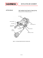
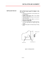
www.harricksci.com
HIGH TEMPERATURE
REACTION CHAMBER
USER’S MANUAL
HARRICK SCIENTIFIC PRODUCTS, INC.
141 Tompkins Ave, 2nd floor • Pleasantville, NY 10570 • (800) 248-3847 • FAX (914) 747-7209
TABLE OF CONTENTS
General Information
Unpacking ....................................................................................................................................
Technical Support ........................................................................................................................
Feedback .....................................................................................................................................
1
1
1
About the High Temperature Reaction Chamber .........................................
2
Installation and Alignment
Getting Ready ..............................................................................................................................
Window Installation ......................................................................................................................
Dome Installation .........................................................................................................................
Installing the HVC ........................................................................................................................
Fluid/Electrical Connections ........................................................................................................
3
4
5
6
7
Operation
Collecting the Background/Baseline Spectrum ...........................................................................
Sample Spectrum ........................................................................................................................
8
9
Options
Cooling Cartridge.......................................................................................................................... 10
Purge Shield ................................................................................................................................. 12
HVC Maintenance
Leak Checking .............................................................................................................................
Cleaning the HVC ........................................................................................................................
Replacing the O-rings ..................................................................................................................
Replacing the Heater and/or Thermocouple ................................................................................
14
14
14
15
Appendix
Optional and Replacement Parts ................................................................................................ 16
HVC-M
GENERAL INFORMATION
UNPACKING
Before installing the High Temperature Reaction Chamber
make sure all the parts on the included check list are
present. If any parts are missing or damaged, contact
Harrick Scientific immediately.
TECHNICAL SUPPORT
For additional information please contact our
Technical Support Center at 800-248-3847 between 9 a.m.
and 5 p.m. EST; or e-mail your questions to:
[email protected]
FEEDBACK
Your comments and suggestions are welcome.
Please send them to:
Harrick Scientific Products, Inc.
PO Box 277
141 Tompkins Ave, 2nd floor
Pleasantville, NY 10570
Phone: 800-248-3847; Fax: 914-747-7209
E-mail: [email protected]
Web: www.harricksci.com
1 of 16
ABOUT THE HVC
ABOUT THE HIGH TEMPERATURE REACTION CHAMBER (HVC)
The HVC is designed for operation up to 910°C under vacuum (the lifetime of the heater is
significantly reduced at temperatures above 450°C). The pressure range is from high vacuum to
pressures up to 3.44MPa or 25.8 ktorr (the high pressure dome is required for pressures above
133 μPa or 1 ktorr). At higher pressures, the maximum operating temperature may be lower.
The HVC is made of chemically resistant 316 stainless steel. Within the chamber is a
temperature-controlled sample stage with integral sample cup. This stage incorporates a
cartridge heater and a thermocouple. It is thermally isolated from the outer chamber wall. A
water-cooling jacket controls the temperature of the outer surface of the chamber and windows
during high or low temperature operation. The reaction chamber has three gas ports for
evacuating, pressurizing or flowing gas through the sample. These ports are equipped with 1/4”
VCO fittings. One of the ports leads directly under the sample cup; the other two lead into the
sides of the chamber.
The chamber is enclosed with a dome with three windows, two for the spectrometer radiation to
enter and exit the chamber and the third for viewing, illuminating, or irradiating the sample. This
enables the use of the reaction chambers for photochemical studies. For IR operation the
standard material for the observation window is UV quartz and KBr for the other two windows. For
UV-VIS operation the standard material for all three windows is UV quartz.
CAUTION:
Parts for the high pressure and low pressure domes should not be exchanged. The high
pressure domes undergo high pressure testing and are guaranteed to work under the rated
pressure.
2 of 16
INSTALLATION AND ALIGNMENT
GETTING READY
Before installing the High Temperature Reaction Chamber
(HVC) familiarize yourself with it by referring to the
drawing of the HVC found below (Figure 1).
HVC Dome
Gas Inlet/Outlet
Gas Outlet
Mounting pins (2)
Thermocouple
Connector
Cooling Ports
Gas Inlet/Outlet
Heater
Connector
Heater Access Hole
Figure 1 • The High Temperature Reaction Chamber HVC
3 of 16
INSTALLATION AND ALIGNMENT
WINDOW INSTALLATION
If the windows are not already installed or need to be
cleaned or changed follow the steps below (Figure 2).
NOTE:
The observation window is the window that is located
between the two semicircular indentations on the rim of
the dome.
• Insert an o-ring in one of the window ports.
• Hold the retaining ring upside-down and
place a PTFE washer inside.
• Then carefully place a window on top of the
PTFE washer.
• Hold the retaining ring so that it continues to
retain the window and thread it into the
window port.
• Tighten to secure the window in place using
the tool provided for tightening and loosening
the retaining rings.
• Repeat these steps until all three windows
are installed.
NOTE:
Be careful not to touch the windows during installation.
Retaining Ring
Window
Dome
PTFE Washer
O-Ring
Semicircular Indentation (2)
Figure 2 • Installing the HVC Dome Windows
4 of 16
INSTALLATION AND ALIGNMENT
DOME INSTALLATION
Although it is not necessary to install the dome until later,
it is recommended to become familiar with the procedure
before proceeding to the next step.
• Prior to installation of the dome make sure that
the o-ring and groove on the bottom of the dome
are clean and free of dust.
• Retract the retaining plates on the HVC as far as
possible.
• Install the dome making sure that the orientation
slot on the dome engages the orientation pin on
the HVC (Figure 3).
• Slide the retaining plates all the way over the rim
of the dome.
• Tighten the retaining plate screws to secure the
dome.
Orientation slot
Retaining Plate Screws (4)
Orientation pin
Retaining Plate (2)
Figure 3 • Installing the HVC Dome
5 of 16
INSTALLATION AND ALIGNMENT
INSTALLING THE HVC
Before installing the HVC in the Praying Mantis™, make
sure that the Praying Mantis™ is aligned in the
spectrometer.
• Unscrew the thumbscrew on the top plate of the
Praying Mantis™.
• Carefully swing the top plate of the Praying
Mantis™ out of the way.
• Grasp the sample stage (Figure 4) and unscrew
its mounting screw.
• Slide the sample stage slightly to the left to
dislocate its mounting pins.
• Remove the sample stage.
• Locate the mounting pins on the side of the HVC
in the pin holes where the sample stage was
located.
• Reinstall and tighten the sample stage mounting
screw.
Mounting Screw
Sample stage
Mounting Pins (2)
Figure 4 • Installing the HVC
6 of 16
INSTALLATION AND ALIGNMENT
Gas Inlet/Outlet
Gas Outlet
Thermocouple
Cooling
Ports
Heater
Gas Inlet/Outlet
Figure 5 • The HVC Installed
•
FLUID / ELECTRICAL
CONNECTIONS
NOTE:
If temperature control is desired, connect the
thermocouple and the heater (Figure 5) to a
suitable temperature controller.
• If the HVC is to be operated at temperatures
above 100°C, use 1/4” tubing to connect the two
cooling ports (see Figure 5) to a water inlet/outlet
or a coolant circulator. If needed, use a hose
clamp to secure the tubing to the barbed fitting.
• If vacuum is desired, connect the gas outlet (1/4”
VCO fitting, see Figure 5) to a vacuum pump or
other source of vacuum using 3/8” I.D. vacuum
tubing. Seal off the two gas inlet/outlet ports.
• If reaction or process gas/es are to be passed
through the sample, connect the gas inlet/out
ports (1/4” VCO fitting, see Figure 5) as needed
to the gas source/s. Connect the gas outlet and
seal off any unused gas ports.
• If reaction or process gas/es are to be passed
over the sample, seal off the gas outlet. Connect
one of the gas inlet/outlet ports to the gas source
and the other as the outlet.
Operation above 800ºC increases the thermal stress on
the o-rings and windows. Be sure to check their
condition regularly during high temperature operation.
Continued operation at or near the high temperature limit
of the cell will reduce the lifetime of the heater.
CAUTION:
Do not overtighten the VCO fittings. These are o-ring sealed fittings and they only need to
be finger-tight to seal. If this is not sufficient, inspect the o-ring and replace as needed.
7 of 16
OPERATION
COLLECTING THE
BACKGROUND/BASELINE
SPECTRUM
•
•
•
•
•
•
•
•
•
Place a sample screen into the sample cup and
locate the plastic overflow tray over the sample
cup (Figure 6).
Fill the sample cup with the reference material
using the provided packing tool.
Draw the
straightedge across the top of the cup to level off
the surface.
Carefully remove the overflow tray.
Install the dome on the HVC.
Swing the Praying Mantis™ cover back into place
and tighten the thumbscrew.
Set the temperature and pressure to desired
operating conditions.
Set the spectrometer to measure the “energy” on
the detector for IR operation. For UV-VIS
spectrometers with a micro switch, with the
spectrometer in %T mode, hold the micro switch
to activate the detector.
Adjust the micrometer to maximize the signal on
the detector.
Collect the background spectrum.
Sample Cup
Overflow Tray
Figure 6 • Filling the Cup
NOTE:
For best results, the reference material, a non-absorbing
powder or rough surfaced solid, should be ground as
finely as possible and packed tightly into the sample cup.
8 of 16
OPERATION
•
SAMPLE SPECTRUM
•
•
•
•
•
•
•
•
•
•
NOTE:
Restore the reference material to ambient
conditions.
Remove the dome.
Empty the sample cup. This can be done by
vacuuming out the reference sample or by
removing the HVC from the Praying Mantis™ and
dumping out the material.
If needed, clean the sample cup.
Fill the sample cup with the sample (follow
procedure in the alignment section).
Install the dome.
Install the HVC into the Praying Mantis™ if it was
removed to empty the sample cup.
Swing the top plate back into place and tighten
the thumbscrew.
Restore the desired sampling conditions.
Collect the sample spectrum.
Empty the sample cup and clean it before
running the next sample.
For best results, use powdered samples in low
concentration, diluting as needed with a non-absorbing
powder such as that used for the reference.
9 of 16
OPTIONS
ABOUT THE COOLING
CARTRIDGE
This optional cooling cartridge is designed to slide into
the HVC instead of the supplied heater for moderate
heating or cooling of the sample. It readily connects to
chillers or recirculators using ¼” ID tubing.
INSTALLATION
•
REMOVING THE HEATER
•
•
•
•
•
•
•
Remove the HVC from the Praying Mantis™ if it
is installed.
Use a 3/32 ball driver to unfasten the screw in the
mounting block on the side of the HVC and
remove the mounting block.
Use a flat blade screwdriver to remove the screw
and clamp on the back of the HVC that anchors
the heater and thermocouple wire to the HVC.
Push a small, blunt object through the heater
access hole at the front of the HVC.
Slide the heater out the back of the unit.
Locate the mounting block on its pins with the
thermocouple wire passing through the slot.
Use a 3/32” hex-head driver to screw the
mounting block back onto the side of the HVC.
Use the new thermocouple (TC) clamp provided
to re-secure the thermocouple wire.
Mounting Block
Screw
Clamp
Clamping
Screw
Figure 7 • Removing the Heating Cartridge
10 of 16
OPTIONS
•
•
INSTALLING THE COOLING
CARTRIDGE
Slide it into the HVC until it hits the stop.
Use a 1/16” hex-head driver to clamp the cooling
cartridge in place as shown using, the clamp and
screw provided.
TC Clamp
Cooing
Cartridge
Screw
TC Clamping
Screw
Clamp
Figure 8 • Installing the Cooling Cartridge
•
•
Install the HVC in the Praying Mantis™ and
install it into the spectrometer.
Connect ¼” ID tubing from the barbed fittings to
the chiller or recirculator.
Barbed Fittings (2)
Figure 9 • Cooling Cartridge Installed
NOTE:
There is a temperature differential between the set
temperature of the chiller or recirculator and the sample
cup due to thermal losses through the tubes, etc. Use
the HVC thermocouple to monitor this differential and
fine-tune the set temperature as needed.
11 of 16
OPTIONS
ABOUT THE PURGE SHIELD
This optional purge shield slips into the Praying Mantis to
improve the purge sealing around the front of the HVC.
•
INSTALLATION
•
•
•
•
Unscrew the thumbscrew on the top plate of the
Praying Mantis™.
Carefully swing the top plate of the Praying
Mantis™ out of the way.
If the sampling stage or HVC is installed in the
Praying Mantis™, unscrew the mounting screw
and remove the sampling stage.
Slide the purge shield into the Praying Mantis,
directly behind the front of the accessory, as
shown in Figure 10.
Push the purge shield slider up to allow room for
installation of the HVC.
Purge Shield Slider
Purge Shield
Figure 10 • Removing the Heating Cartridge
NOTE:
The purge shield is transparent, allowing easy viewing of
the sample. It is not, however, intended for use in
conjunction with sample illumination through the
observation window.
12 of 16
OPTIONS
•
•
•
•
•
Feed the HVC through the purge shield.
Locate the mounting pins on the side of the HVC
in the pin holes where the sample stage was
located.
Reinstall and tighten the sample stage mounting
screw.
Push the purge shield slider down to seal the
front of the HVC.
Continue setting up the HVC as described
previously.
Figure 11 • Removing the Heating Cartridge
13 of 16
HVC MAINTENANCE
LEAK CHECKING
The HVC has been carefully checked for leaks before
shipment. However, each time the HVC is disassembled
and reassembled, leaks may develop due to improper
setting of the o-rings. If leaks occur, carefully inspect all
o-rings and sealing surfaces for damage and
contamination. Small leaks can be pinpointed using a
Helium Leak Detector.
Contact Harrick Scientific
Products, Inc. for advice and/or repair information.
CLEANING THE HVC
To thoroughly clean the HVC follow the procedure below.
•
•
•
•
•
•
•
REPLACING THE O-RINGS
Vacuum out the sample or remove the HVC from
the Praying Mantis™, remove the dome, turn the
HVC upside-down and dump out the sample.
Use solvent to clean off the remaining sample.
Unscrew the eight screws that secure the bottom
cover of the HVC.
Remove the bottom cover to reveal three access
holes.
Gingerly wipe or blow clean air through these
holes to clean the interior of the HVC.
When the interior is clean, make sure the o-rings
on the bottom plate are clean and free of dirt.
Re-install the bottom cover.
The o-rings used by the HVC should be replaced
periodically.
The HVC has o-rings for sealing the
windows, o-rings for sealing the access holes, o-rings on
the fittings, and an o-ring to seal the dome to the HVC.
14 of 16
HVC MAINTENANCE
REPLACING THE HEATER
AND/OR THERMOCOUPLE
To replace the HVC heater:
• Remove the HVC from the Praying Mantis™ if it
is installed.
• Use a 3/32 ball driver to unscrew the screw in the
mounting block on the side of the HVC and
remove the mounting block.
• Use a slotted screwdriver to remove the screw
and clamp on the back of the HVC that anchors
the heater and thermocouple wire to the HVC.
• Grasp the heater wires firmly and slide the heater
out.
• If replacing the thermocouple, slide the old
thermocouple out of the HVC. Then insert the
new thermocouple into the small hole (see Figure
13) as far as it will go.
• Slide the heater into the HVC until it hits the stop.
Make sure that the heater and thermocouple are
inserted completely into the body.
• Position the mounting block onto the side of the
HVC, feeding the three wires along the recess in
the block.
• Then use a 3/32 ball driver to secure the
mounting block in place.
• Reinstall the clamp to secure the wires to the
back of the HVC.
Mounting Block
Screw
Clamp
Clamping
Screw
Figure 12 • Removing the Heating Cartridge and/or
Thermocouple
Thermocouple Hole
Heater Hole
Figure 13 • Installing the Heating Cartridge and/or
Thermocouple
15 of 16
APPENDIX
OPTIONAL PARTS
Temperature Controller, 110V input, 24V output ....................................................
Temperature Controller, 220V input, 24V output ....................................................
RS-485 to USB Adapter for the Temperature Controller ........................................
Vacuum Pump, 110V ..............................................................................................
Vacuum Pump, 220V ..............................................................................................
High Pressure Dome for the HVC-DRP, ZnS Windows .........................................
High Pressure Dome for the HVC-DRP, ZnSe Windows .......................................
High Pressure Dome for the HVC-DRP, UV Quartz Windows ...............................
ZnS Window for the HVC-DRP High Pressure Dome ............................................
ZnSe Window for the HVC-DRP High Pressure Dome ..........................................
UV Quartz Window for the HVC-DRP High Pressure Dome ..................................
UV Quartz Window for the Vacuum/Low Pressure Domes ....................................
Si Window for the Vacuum/Low Pressure Domes ..................................................
CaF2 Window for the Vacuum/Low Pressure Domes ............................................
ZnS Window for the Vacuum/Low Pressure Domes ..............................................
ZnSe Window for the Vacuum/Low Pressure Domes ............................................
KBr Window for the Vacuum/Low Pressure Domes ...............................................
Cooling Cartridge ....................................................................................................
Purge Shield ...........................................................................................................
ATC-024-3
ATC-024-4
ATC-USB-485
VPE-001
VPE-002
HVC-DWI-3
HVC-DWM-3
HVC-DWA-3
WID-U43
WMD-U43
WAD-U43
WAD-U23
WED-U23
WFD-U23
WID-U23
WMD-U23
WPD-U23
HVC-COL
DRP-PDR
REPLACEMENT PARTS
Overflow tray, 11.0 mm ID .......................................................................................
Packing Tool ...........................................................................................................
Screen Set, two each of three mesh sizes, 4.7 mm dia. .........................................
Screen Set, 150 x 150 mesh (6), 4.7 mm dia. ........................................................
Screen Set, 250 x 250 mesh (6), 4.7 mm dia. .........................................................
Screen Set, 400 x 400 mesh (6), 4.7 mm dia. .........................................................
K-Type Thermocouple ............................................................................................
Flex Mounting Plugs – Male ...................................................................................
1.00”x0.25” Cartridge Heater, 100W, 24V ..............................................................
24V Heater Assembly .............................................................................................
O-Ring (#10) for the VCO Fittings, Viton ................................................................
O-Ring (#10) for the VCO Fittings, Kalrez ..............................................................
O-Ring (#16) for the Bottom Cover, Viton ..............................................................
O-Ring (#16) for the Bottom Cover, Kalrez ............................................................
O-Ring (#23) for the Dome, Viton ...........................................................................
O-Ring (#23) for the Dome, Kalrez .........................................................................
O-Ring (#13) for Windows of the Dome, Viton .......................................................
O-Ring (#13) for Windows of the Dome, Kalrez ....................................................
PTFE Washer for the Windows ..............................................................................
UV Quartz Window for the Vacuum/Low Pressure Domes ....................................
UV Quartz Window for the HVC-DRP High Pressure Dome ..................................
KBr Window for the Vacuum/Low Pressure Domes ...............................................
16 of 16
116-989
116-836
116-990
116-990-1S
116-990-2S
116-990-3S
008-144
008-266
HTRS-26
HVC-HT4
ORV-010
ORK-010
ORV-016
ORK-016
ORV-023
ORK-023
ORV-013
ORK-013
116-429
WAD-U23
WAD-U43
WPD-U23
Manual Part No. HVC-M-09
©2013 Harrick Scientific Products, Inc.