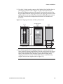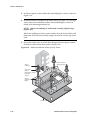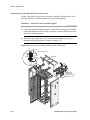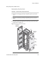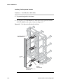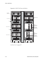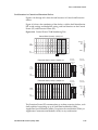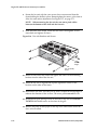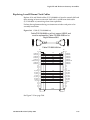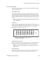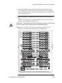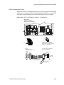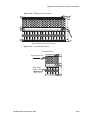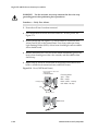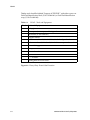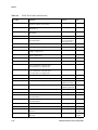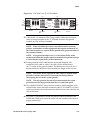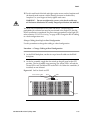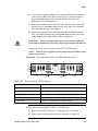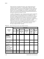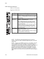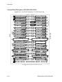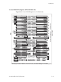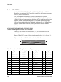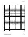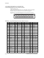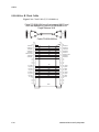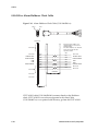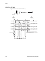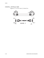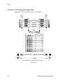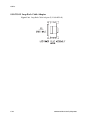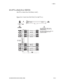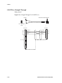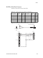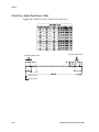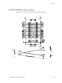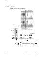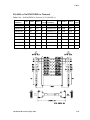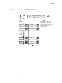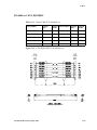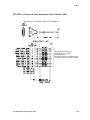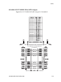
1
Tekelec Signaling Products Installation - Eagle Table of Chapters Table of Contents List of Figures List of Tables List of Procedures Chapter 1. Introduction Chapter 2. General Installation Information Chapter 3. Frames and Shelves Chapter 4. Fuses and Breakers Chapter 5. Eagle STP and IP7 Secure Gateway Assemblies Chapter 6. EOAP Appendix A. LEDs Appendix B. Connectors Appendix C. Cables Appendix D. Power Cords to Peripherals Index 910-4601-01 Revision D, May 2005 910-4601-01 Revision D, May 2005 Tekelec Signaling Products Installation - Eagle 910-4601-01 Revision D May 2005 © 2003, 2004, 2005 Tekelec All Rights Reserved Printed in U.S.A. Notice Information in this documentation is subject to change without notice. Unauthorized use or copying of this documentation can result in civil or criminal penalties. Any export of Tekelec products is subject to the export controls of the United States and the other countries where Tekelec has operations. No part of this documentation may be reproduced or transmitted in any form or by any means, electronic or mechanical, including photocopying or recording, for any purpose without the express written permission of an authorized representative of Tekelec. Other product names used herein are for identification purposes only, and may be trademarks of their respective companies. Trademarks The Tekelec logo, EAGLE, G-Port, and G-Flex, IP7, and IP7 Secure Gateway are registered trademarks of Tekelec, Inc. Patents This product is covered by one or more of the following U.S. and foreign patents: U.S. Patent Numbers: 5,008,929, 5,953,404, 6,167,129, 6,324,183, 6,327,350, 6,606,379, 6,639,981, 6,647,113, 6,662,017, 6,735,441, 6,745,041, 6,765,990, 6,795,546, 6,819,932, 6,836,477, 6,839,423, 6,885,872 Ordering Information Additional copies of this document can be ordered from Tekelec Network Signaling Group, 5200 Paramount Parkway, Morrisville, NC 27560 Table of Contents Chapter 1. Introduction Safety Information.................................................................................... 1-3 Introduction............................................................................................... 1-6 Regulatory, Safety Compliance and Certification......................... 1-8 Environmental Requirements .......................................................... 1-9 Temperature Variation ............................................................... Relative Humidity....................................................................... Elevation ....................................................................................... Building Requirements............................................................... 1-9 1-9 1-9 1-9 Scope and Audience............................................................................... 1-10 Tekelec Signaling Products Systems.................................................... 1-10 Eagle STP........................................................................................... 1-11 IP7 Secure Gateway.......................................................................... 1-11 EOAP ................................................................................................. 1-11 Documentation ....................................................................................... 1-12 About this Manual ........................................................................... 1-12 Admonishments and Conventions ......................................... 1-12 Documentation Suite ....................................................................... 1-13 Documentation Packaging, Delivery, and Updates.................... 1-16 References ......................................................................................... 1-16 Product Packaging and Delivery ......................................................... 1-17 Tekelec Technical Support .................................................................... 1-17 Installation Support ......................................................................... 1-17 Problem – Critical ...................................................................... Problem – Major ........................................................................ Problem – Minor........................................................................ Response ..................................................................................... Emergency Response ................................................................ 1-18 1-18 1-19 1-19 1-19 Hardware Repair and Return ............................................................... 1-20 Repair and Return Shipping Instructions .................................... 1-21 Specifically Targeted PCBs ...................................................... 1-23 Returning a Crate............................................................................. 1-23 Acronyms................................................................................................. 1-25 910-4601-01 Revision D, May 2005 i Table of Contents Doc Assignments (from Software perspective) .................................. 1-31 Chapter 2. General Installation Information NSD Systems Components Overview ................................................... 2-2 Eagle STP and IP7 SG Module Installation............................................ 2-6 Labeling ...................................................................................................... 2-8 Cable Labeling .................................................................................... 2-8 Fuse and Alarm Panel Labeling ..................................................... 2-10 Label Kit for Fuse and Alarm Panel ........................................ 2-10 Hardware Operational Testing ............................................................. 2-11 Temperature Variation.............................................................. 2-11 Relative Humidity ..................................................................... 2-11 Elevation...................................................................................... 2-11 Eagle STP and IP7 SG Post-Installation Inspection ............................ 2-12 Chapter 3. Frames and Shelves Safety and Cautionary Information........................................................ 3-2 Heavy Duty Frame.................................................................................... 3-4 Unpacking ........................................................................................... 3-4 Floor Preparation for Heavy Duty Frame..................................... 3-11 General Floor Preparation ........................................................ 3-11 Recommended Tools ................................................................. 3-11 Raised Floor ................................................................................ 3-14 Recommended Tools ................................................................. 3-14 Concrete Floor ............................................................................ 3-20 Recommended Tools ................................................................. 3-20 Anchoring to Overhead Rack of Heavy Duty Frame.................. 3-24 Heavy Duty Panels and Rear Covers ............................................ 3-25 Removing Heavy Duty Frame Panels..................................... 3-25 Installing Unit Separation Brackets......................................... 3-26 Frame Labeling ................................................................................. 3-27 Shelf Labeling.................................................................................... 3-28 Older Frame Side Panels ................................................................. 3-33 Recommended Tools ................................................................. 3-33 Side Panels .................................................................................. 3-33 Shelves ...................................................................................................... 3-35 Rear Covers................................................................................. 3-37 Chapter 4. Fuses and Alarm Panels Fuse and Alarm Panels............................................................................. 4-2 ii 910-4601-01 Revision D, May 2005 Table of Contents Safety Information ............................................................................. 4-2 Fuse and Alarm Panel Overview..................................................... 4-3 Fuse and Alarm Panel (P/N 870-2320-01 and P/N 870-2320-02) 4-5 Jumper Board Fuse Installation ....................................................... 4-5 Power Cabling Procedure................................................................. 4-8 Recommended Tools................................................................. 4-10 Frame Ground and Logic Ground Cabling Procedures............. 4-13 Grounding Requirements ........................................................ Recommended Tools................................................................. Logic Ground Connections to the System Ground Bar ....... Logic Ground Cables ................................................................ 4-13 4-13 4-16 4-19 Fuse Verification .............................................................................. 4-21 Lists Fuse and Card Locations. ...................................................... 4-24 Card Locations in Control and Extension Shelves...................... 4-35 Chapter 5. Eagle STP and IP7 Secure Gateway Assemblies Safety Information.................................................................................... 5-4 EAGLE 30.0 Specific Information........................................................... 5-6 Intra-system Cable Installation............................................................... 5-7 Recommended Tools ......................................................................... 5-7 Interprocessor Message Transport Cables ..................................... 5-7 Rack Alarm and Row Alarm Cable Routing ......................... 5-11 Interface Cable Installation ................................................................... 5-12 Interface Cable Installation Order ................................................. 5-13 Control Frame CF-00 Backplane ............................................. Extension Frame EF-00 ............................................................. Extension Frame EF-01 ............................................................. Extension Frame EF-02 ............................................................. Extension Frame EF-03 ............................................................. Extension Frame EF-04 ............................................................. 5-13 5-14 5-15 5-16 5-17 5-17 Recommended Tools ....................................................................... 5-18 LAN Ethernet Cable Installation for ACM ......................................... 5-21 Recommended Tools ....................................................................... 5-21 DCM and Fan Option, EDCM, DSM Cabling .................................... 5-25 DCM and EDCM Modules....................................................... 5-25 Database Communications Module ....................................... 5-25 ASM, TDM, and DSM (MCPM) Upgrade Procedures...................... 5-28 Application Service Module (ASM) to Transaction Service Module (TSM-256 or higher) Upgrade for SCCP .................................. 5-28 910-4601-01 Revision D, May 2005 iii Table of Contents Application Service Module (ASM) to Transaction Service Module (TSM-256 or higher) Upgrade for GLS .......................................................................... 5-32 Terminal Disk Module (TDM) Upgrade ....................................... 5-36 Measurement Collection and Polling Module (MCPM)............. 5-45 Removing a Card in an Existing EAGLE System ........................ 5-51 Fan Assembly Installation and Cabling............................................... 5-54 Installing Fan Assembly 890-0001-01 ............................................ 5-54 Installing Fan Cables........................................................................ 5-64 Powering Up the Fan Assembly..................................................... 5-66 Installing Fan Assembly 890-1038-01 or 890-1038-02 .................. 5-68 Installing Fan Cables........................................................................ 5-73 Powering Up the Fan Assembly..................................................... 5-75 Testing the Fan Assembly ............................................................... 5-77 Clock Cable Installation ......................................................................... 5-79 Testing the Cables ...................................................................... 5-80 Master Timing (Eagle STP) .................................................................... 5-81 Master timing Overview ................................................................. 5-81 Master Timing Site Requirements.................................................. 5-83 Master timing Feature Requirement Matrix................................. 5-83 Termination of Alarm, Clock Supply, and Terminal Cables ............ 5-85 Recommended Tools........................................................................ 5-85 Alarm Cables..................................................................................... 5-86 Integrated Timing System Clock Supply Cables ......................... 5-88 Replacing A and B Frame Clock Cables .............................................. 5-89 Replacing A and B Frame Clock Cables .............................................. 5-91 Replacing A and B Frame Clock Cables Introduction ................ 5-91 Replacing A and B Frame Clock Cables Description .................. 5-91 Terminal Cables .............................................................................. 5-107 Holdover Clock Installation ................................................................ 5-108 Card Placement............................................................................... 5-108 Recommended Tools...................................................................... 5-108 Output Panel Connections ............................................................ 5-109 TOCA Ribbon Cables .............................................................. 5-109 TOLA Card ............................................................................... 5-109 Output Panel Frame Ground ................................................. 5-109 Power Connections .................................................................. 5-109 Holdover Clock Switch Settings................................................... 5-110 iv 910-4601-01 Revision D, May 2005 Table of Contents Clock Input DIP Switch Settings.................................................. 5-110 Output Panel Connections............................................................ 5-112 Clock Output Connections..................................................... 5-112 Holdover Clock Alarm Connections........................................... 5-112 BITS Clock Source Cables....................................................... 5-115 Replacing Holdover Clock Rear Cover....................................... 5-116 Holdover Clock Fuses ................................................................... 5-117 E1-T1 Interface ...................................................................................... 5-118 E1 Introduction............................................................................... 5-118 Configured as an LIM E1 Card .................................................... 5-119 Configured as a Channel Card..................................................... 5-119 E1/T1 MIM, P/N 870-2198-02 ..................................................... 5-119 Installing E1 Interface Module Kit ........................................ 5-121 Recommended Tools............................................................... 5-121 Design Considerations for E1....................................................... 5-123 External Interface Descriptions ............................................. 5-123 Possible Configurations.......................................................... 5-124 High Level Functional Description....................................... 5-124 E1/T1 MIM, .................................................................................... 5-125 Installing E1/T1 Patch Cables...................................................... 5-129 LIM-E1/T1 Card Installation.............................................................. 5-132 E1/T1 Configuration Form .................................................... 5-132 Multi-Port LIM (MPL) ........................................................................ 5-133 MPL Card Diagnostic Cable......................................................... 5-135 Ohms Converter International Market.............................................. 5-136 Hardware Acceptance ......................................................................... 5-140 Introduction .................................................................................... 5-140 Fuse Verification ............................................................................ 5-142 Frame Fuse Assignments .............................................................. 5-144 Control and Extension Shelves .................................................... 5-157 –48VDC Power Source......................................................................... 5-162 Verification of Fuse Alarm Function .................................... 5-163 Chapter 6. EOAP Safety Information.................................................................................... 6-2 Introduction............................................................................................... 6-5 EOAP.......................................................................................................... 6-8 Overview............................................................................................. 6-8 910-4601-01 Revision D, May 2005 v Table of Contents EOAP Fan Assembly........................................................................ 6-14 Install Cooling Duct................................................................... 6-20 EOAP Shelf ........................................................................................ 6-21 EOAP Cabling ................................................................................... 6-26 EOAP Cabling Overview.......................................................... 6-26 Single-Configuration Cabling .................................................. 6-35 Dual-Configuration Cabling .................................................... 6-38 Single-to-Dual Configuration Cabling.................................... 6-59 EOAP Power-Up............................................................................... 6-73 Fan Operation Testing ..................................................................... 6-74 Maintenance Modem Setup ............................................................ 6-77 EOAP Test Procedures..................................................................... 6-79 Overview..................................................................................... 6-79 Test Setup .................................................................................... 6-80 EOAP Tests ................................................................................. 6-81 Initial conditions: ....................................................................... 6-95 EOAP Provisioning ........................................................................ 6-101 Before You Start Read This ........................................................ 6-101 Tools and Equipment .................................................................. 6-103 Configuring EOAP System Parameters................................ 6-103 EOAP Initial Implementation............................................................. 6-104 Reprovisioning................................................................................ 6-134 Changing the EOAP Configuration ...................................... 6-134 Example of EOAP Configuration Changes .......................... 6-134 GR-376 EOAP ........................................................................................ 6-149 Overview................................................................................... 6-149 GR-376 EOAP Installation............................................................. 6-154 VI Editor Quick Reference ................................................................... 6-164 Appendix A. LEDs Circuit Card LEDs.................................................................................... A-3 Introduction........................................................................................ A-3 ACM, Application Communication Module................................. A-4 ASM, Application Service Module ................................................. A-5 ATM-LIM, AINF-LIM, E1-LIM, EILA, ILA ................................... A-6 CI, Clock Interface Card, Holdover Clock ..................................... A-7 DCM and DSM .................................................................................. A-8 DS0A-LIM, Digital Signal Level-0 LIM .......................................... A-9 E1 ATM Link Interface Module..................................................... A-10 vi 910-4601-01 Revision D, May 2005 Table of Contents E1/T1 MIM, P/N 870-2198-01 ...................................................... A-11 E1/T1 MIM, P/N 870-2198-02 ...................................................... A-12 EDCM (Double-Slot), Enhanced DCM Card .............................. A-13 EDCM (Single-Slot), Enhanced DCM Card ................................ A-14 EOAP, Embedded OAP ................................................................. A-15 General Purpose Service Module (GPSM-II) .............................. A-16 GR-376 Processor ............................................................................ A-17 HMUX, High-Speed Multiplexer ................................................. A-18 ILE1 Integrated Link Interface Module E1.................................. A-19 IPMX, Inter processor Message Transport Multiplexer ............ A-20 MCA, Matrix Controller Assembly Card Holdover Clock ....... A-21 MCAP, MAS Communications Applications Processor ........... A-22 MDAL, Maintenance Disk and Alarm Card ............................... A-23 MIS, Maintenance Interface System Card, Holdover Clock ..... A-24 MPL-LIM, Multi-Port Link Interface Module............................. A-25 MPLT, Multi-Port LIM with Taxi Component ........................... A-26 OCU-LIM, Office Channel Unit-LIM ........................................... A-27 ST3, Stratum-3 Clock Card, Holdover Clock .............................. A-28 TDM, Terminal Disk Module........................................................ A-29 TDM-GTI, Terminal Disk Module-Global Timing Interface .... A-30 TOCA, Holdover Clock.................................................................. A-32 V.35-LIM Link Interface Module .................................................. A-33 Appendix B. Connectors A Clock 0 through A Clock 5 .................................................................. B-5 B Clock 0 through B Clock 5 .................................................................. B-7 BITS Clock ................................................................................................ B-9 Clock A In/Out....................................................................................... B-10 Clock A In Connector ...................................................................... B-10 Clock A Out Connector................................................................... B-11 Clock A/B In/Out Extension Shelf...................................................... B-12 Clock A In Connector J5.................................................................. B-12 Clock B In/Out ....................................................................................... B-13 Clock B In Connector....................................................................... B-13 Clock B Out Connector ................................................................... B-14 Clock A Out Connector J6 .............................................................. B-15 Clock B In Extension Shelf Connector J41 .................................... B-16 Clock B Out Extension Shelf Connector J42................................. B-17 910-4601-01 Revision D, May 2005 vii Table of Contents Control Shelf Backplane (P/N 850-0330-03/04) ................................ B-18 Control Shelf Backplane (P/N 850-0330-06) ...................................... B-19 Control Shelf Modules .......................................................................... B-20 ACM/ASM/DCM/DSM/EILA/ILA/LIM/MPL/TSM Control Shelf Backplane Pin-Outs, Top Connector ............... B-20 ACM/ASM/DCM/DSM/EILA/ILA/LIM/MPL/TSM Control Shelf Backplane Pin-Outs, Bottom Connector.......... B-22 Extension Backplane (P/N 850-0356-01) ............................................ B-25 Extension Shelf Backplane (P/N 850-0356-01) ............................ B-25 Extension Shelf Backplane (P/N 850-0356-03) ............................ B-26 Extension Shelf Backplane (P/N 850-0356-04) ............................ B-27 Extension Shelf Modules....................................................................... B-28 ACM/ASM/DCM/DSM/EILA/ILA/LIM/MPL/TSM .......... B-28 Extension Shelf Interface....................................................................... B-33 External Alarm ....................................................................................... B-35 Fan Power................................................................................................ B-36 Fuse and Alarm Panel (P/N 870-2320-01).......................................... B-37 General Purpose Relay Connector 01.................................................. B-38 General Purpose Relay Connector 02.................................................. B-39 General Purpose Serial Interface.......................................................... B-40 High Speed Message Multiplexer Control Shelf ............................... B-41 Control Shelf HMUX A Backplane P8.......................................... B-41 Control Shelf HMUX B Backplane P24......................................... B-43 High Speed Message Multiplexer Extension Shelf ........................... B-46 Interface Backplane Control ................................................................. B-49 Inter processor Message Transport Control Shelf............................. B-51 Interprocessor Message Transport ...................................................... B-52 IPMX Connector J7, J8, J43, J44 ............................................... B-52 Local Maintenance Center Alarm Backplane..................................... B-53 MAS Communication Application Processor.................................... B-54 Maintenance Disk and Alarm Card Control Shelf Backplane......... B-57 OAP Alarm Backplane .......................................................................... B-60 Power Connector Extension Backplane .............................................. B-61 Power Connector Control Backplane.................................................. B-62 Rack Alarm (Alarm Interface).............................................................. B-63 Rack Alarm Control Backplane............................................................ B-64 Remote Maintenance Center Alarm Control Backplane .................. B-65 viii 910-4601-01 Revision D, May 2005 Table of Contents Row Alarm Control Backplane............................................................. B-66 Serial Port Control Backplane............................................................... B-67 Shelf Power.............................................................................................. B-68 Shelf Power Connector P1, P2, P3 ........................................... B-68 Terminal Disk Module Control Backplane ......................................... B-70 Appendix C. Cables Cables by Part Numbers......................................................................... C-1 Labeling..................................................................................................... C-4 Cable Labeling................................................................................... C-4 Introduction.............................................................................................. C-6 803-0029-01 MPL Card Diagnostic Cable............................................. C-7 804-0176-01 Converter ............................................................................ C-7 830-0224-xx Drive Power Cable............................................................. C-8 830-0231-xx Local Maintenance Center Cable..................................... C-9 830-0232-xx Row Alarm Cable ............................................................ C-10 830-0233-xx Remote Maintenance Center Cable............................... C-11 830-0257-xx Hazard Ground Cable..................................................... C-12 830-0315-xx Power Cable...................................................................... C-13 830-0366-xx Interface Cable.................................................................. C-14 830-0398-xx B Clock Cable ................................................................... C-15 830-0404-xx B Clock Cable ................................................................... C-16 830-0421-xx CD ROM Cable................................................................. C-17 830-0425-01 Adapter 15 Pin to 26 Pin ................................................. C-18 830-0435-xx External Alarm Cable (Custom) .................................... C-19 830-0543-xx Alarm Holdover Clock Cable ........................................ C-20 830-0527-xx RS232 ................................................................................. C-21 850-0514-01 Serial I/O Transition Card ............................................. C-22 830-0531-03 Serial Interface Adapter/MODEM ............................... C-23 830-0531-01 Serial Interface Converter Cable.................................... C-24 830-0528-01 Terminal/Converter Cable............................................. C-25 830-0531-02 Serial Interface, Terminal and Printer Adapter ........... C-26 830-0535-xx Terminal/Printer Cable .................................................. C-27 830-0605-xx E1 Patch Cable.................................................................. C-28 830-0609-01 Included Fan Assembly .................................................. C-29 830-0622-xx E1 Cable............................................................................. C-30 830-0624-xx Cable Assembly, BNC to BCN....................................... C-31 830-0625-xx Cable BNC/Open End .................................................... C-32 910-4601-01 Revision D, May 2005 ix Table of Contents 830-0638-xx Filter Rack Alarm Cable .................................................. C-33 830-0651-xx –48V Power Cable ............................................................ C-34 830-0656-01 Fifty Position Cable Hard Drive I/O............................. C-35 830-0657-XX Clock Connection ............................................................ C-36 830-0708-xx MMI Port Cable ................................................................ C-37 830-0709-xx Modem/Terminal Cable ................................................. C-38 830-0710-xx Network Cable.................................................................. C-39 830-0711-xx DCM, 100-BASE TX Interface ......................................... C-40 830-0723-xx CAT-5 Crossover Cable ................................................... C-41 830-0724-xx CAT-5 Straight Trough Cable......................................... C-42 830-0759-xx Null Modem Cable........................................................... C-43 830-0763-01 Loop Back Cable Adapter ............................................... C-44 830-0772-xx Multi-Port LIM DS0 ......................................................... C-45 830-0788-xx Straight Through .............................................................. C-46 830-0789-xx Patch Panel Crossover ..................................................... C-47 830-0814-xx Multi-Port Power Cable................................................... C-48 830-0846-01 HS Master Timing Adapter............................................. C-49 830-0849-xx DS1 Cable .......................................................................... C-50 830-0859-xx Null-MODEM for Terminal............................................ C-51 830-0866-xx Power Cable Breaker To Terminal Strip ....................... C-52 830-0869-xx Power DC Router ............................................................. C-53 830-0872-xx Power DC RAID ............................................................... C-54 830-0892-xx Multi-Port LIM DS0 (24 AWG) ...................................... C-55 830-0908-xx Power Ring ........................................................................ C-56 830-0857-01 Adapter Cable HMUX ..................................................... C-57 830-0884-01 Switch to Frame Ground Cable ...................................... C-58 830-0888-xx CAT-5, RJ45/RJ45............................................................. C-59 830-0889-xx CAT-5, RJ45/RJ45............................................................. C-60 830-0895-01 T1 LIM to MPL Cable Adapter....................................... C-61 830-0900-xx Alarm NETRA Server Cable........................................... C-62 830-0901-xx Tone and Announcement Server Alarm Cable............ C-63 830-0917-01 Adapter RJ 45 to 9 Pin...................................................... C-64 830-0932-01 E1-T1 MIM 22 AWG......................................................... C-65 830-0948-01 E1/T1 MIM LIM 4 Port 24 AWG ................................... C-66 830-0949-01 E1/T1 MIM LIM to MPL Adapter ................................. C-67 850-0496-01 Force Transition Card ...................................................... C-68 x 910-4601-01 Revision D, May 2005 Table of Contents Appendix D. Power Cords to Peripherals International Power Cords..................................................................... D-2 Index 910-4601-01 Revision D, May 2005 xi Table of Contents xii 910-4601-01 Revision D, May 2005 List of Figures Figure 2-1. Removing an Eagle STP and IP7 SG card ............................... 2-7 Figure 2-2. Installer’s Cable Running List Example .................................. 2-8 Figure 3-1. Removing an Eagle STP/IP7 SG Card ..................................... 3-3 Figure 3-2. Shipping Container for Heavy Duty Frame ........................... 3-5 Figure 3-3. Shipping Container for Heavy Duty Frame ........................... 3-6 Figure 3-4. Shipping, Detach Dolly Heavy Duty Frame .......................... 3-7 Figure 3-5. Heavy Duty Frame Dolly .......................................................... 3-8 Figure 3-6. Heavy Duty Frame with Dolly ................................................. 3-9 Figure 3-7. Typical Frame Layout .............................................................. 3-11 Figure 3-8. Typical Floor Layout for Frames ............................................ 3-12 Figure 3-9. Isolation Sheet/Template for Frame ..................................... 3-13 Figure 3-10. Raised Floor Installation Elements ...................................... 3-17 Figure 3-11. Raised Floor With Washers and Nuts ................................. 3-18 Figure 3-12. Raised Floor Installation With Unistrut .............................. 3-19 Figure 3-13. Anchor Assembly ................................................................... 3-21 Figure 3-14. Anchor Installation of Heavy Duty Frame ......................... 3-22 Figure 3-15. Heavy Duty Frame Installation With Cable Rack ............. 3-24 Figure 3-16. Heavy Duty Frame Panels .................................................... 3-25 Figure 3-17. Unit Separation Bracket Installation .................................... 3-26 Figure 3-18. Frame and Shelf Label Locations ......................................... 3-29 Figure 3-19. Heavy-Duty Frame Label Location ..................................... 3-30 Figure 3-20. Frame Label Location - Detail .............................................. 3-31 Figure 3-21. Shelf Label Location - Detail ................................................. 3-31 Figure 3-22. Heavy-Duty Frame Label Location ..................................... 3-32 Figure 3-23. End Panel Self Tapping Screws ............................................ 3-34 Figure 3-24. EAGLE 5 SAS Frame with Door Ground ........................... 3-35 Figure 3-25. EAGLE 5 SAS Frame with Shelves ...................................... 3-36 Figure 3-26. Rear Cover Installation .......................................................... 3-37 Figure 4-1. Fuse and Alarm Panel Location ............................................... 4-3 Figure 4-2. Fuse and Alarm Panel Details .................................................. 4-4 Figure 4-3. FAP P/N 870-2320-xx Front ..................................................... 4-5 Figure 4-4. Jumper Board FAP ..................................................................... 4-6 910-4601-01 Revision D, May 2005 xiii List of Figures Figure 4-5. Jumper Board FAP Fuse ............................................................ 4-6 Figure 4-6. Jumper Board FAP Fuse Installation ....................................... 4-7 Figure 4-7. Fuse and Alarm Panel Rear ...................................................... 4-8 Figure 4-8. Ground Bar and Logic Ground Installation ......................... 4-11 Figure 4-9. System Frame Grounding ....................................................... 4-14 Figure 4-10. System Logic Ground Bar and Cable .................................. 4-17 Figure 4-11. System Logic Grounding ...................................................... 4-18 Figure 4-12. Ground Bar and Logic Ground Installation ....................... 4-20 Figure 4-13. System Logic Ground Connection ....................................... 4-21 Figure 4-14. Alarm Cable Arm ................................................................... 4-21 Figure 4-15. Fuse Holder Locations on FAPs ........................................... 4-34 Figure 4-16. Control Frame CF-00 Numbering Plan ............................... 4-35 Figure 4-17. Extension Frame EF-00 Numbering Plan ........................... 4-36 Figure 4-18. Extension Frame EF-01 Numbering Plan ........................... 4-37 Figure 4-19. Extension Frame EF-02 Numbering Plan ........................... 4-38 Figure 4-20. Extension Frame EF-03 Numbering Plan ........................... 4-39 Figure 4-21. Extension Frame EF-04 Numbering Plan ........................... 4-39 Figure 5-1. Removing a Card ........................................................................ 5-5 Figure 5-2. interprocessor Message Transport Cables .............................. 5-8 Figure 5-3. Three Frame Configuration ...................................................... 5-8 Figure 5-4. Six Frame Configuration ......................................................... 5-10 Figure 5-5. Control Shelf Cabling ............................................................. 5-11 Figure 5-6. Interface Cable Cross-Connect Panel Connection ............... 5-20 Figure 5-7. Adapter Slide Latch ................................................................. 5-23 Figure 5-8. LAN Ethernet Cable Installation ............................................ 5-24 Figure 5-9. DCM Family Cabling, Enhanced Bulk Download .............. 5-26 Figure 5-10. Interface Cable Routing, Control Shelf ............................... 5-27 Figure 5-11. Interface Cable Routing, Extension Shelf ........................... 5-27 Figure 0-1. Push Inject/Eject Clamps Outward ....................................... 5-52 Figure 5-12. Push in Inject/Eject Clamps ................................................. 5-53 Figure 5-13. System Air Baffle .................................................................... 5-55 Figure 5-14. Attach side fan bracket to front frame rail .......................... 5-56 Figure 5-15. Slide the side fan brackets flush with the Frame ............... 5-57 Figure 5-16. Side bracket mounting positions on fan tray bracket. ...... 5-58 Figure 5-17. Insert fan tray bracket ............................................................ 5-59 Figure 5-18. Attaching the fan tray bracket to the side brackets - inside front .................................................................... 5-60 xiv 910-4601-01 Revision D, May 2005 List of Figures Figure 5-19. Fan tray .....................................................................................5-61 Figure 5-20. Fan tray inserted into fan tray bracket in the frame- front view ...................................................................................5-61 Figure 5-21. Tighten rear fan tray screws ..................................................5-62 Figure 5-22. Tighten fan side bracket screws ............................................5-63 Figure 5-23. Fan card with LEDs on front of fan assembly ....................5-66 Figure 5-24. System Air Baffle ....................................................................5-69 Figure 5-25. Fan Assembly with Grill and Filter ......................................5-70 Figure 5-26. Installing Fan Assembly ........................................................5-71 Figure 5-27. Fan Bracket Installation .........................................................5-71 Figure 5-28. Fan with Brackets and Screws ..............................................5-72 Figure 5-29. Front Card Suite with Fan Switch .......................................5-75 Figure 5-30. Fan Assembly with Grill and Filter ......................................5-78 Figure 5-31. Cable (P/N 830-0404-xx) ......................................................5-89 Figure 5-32. Cable (P/N 830-0398-xx) .....................................................5-90 Figure 5-33. Backplane P/N 850-0330-06 Control Shelf ..........................5-98 Figure 5-34. Backplane P/N 850-0356-04 Extension Shelf ......................5-99 Figure 5-35. Clock Cable, A and B clocks ................................................5-102 Figure 5-36. Clock Cable Routing .............................................................5-104 Figure 5-37. Control Shelf (P/N 850-0330-06) BITS Connectors ..........5-105 Figure 5-38. Output Panel Clock Connections .......................................5-106 Figure 5-39. Holdover clock ......................................................................5-108 Figure 5-40. TOLA Master Timing Leads ...............................................5-109 Figure 5-41. Holdover Clock Power Connector .....................................5-110 Figure 5-42. Holdover Clock and Output Panel, Rear ..........................5-111 Figure 5-43. Holdover Clock FAP Connections .....................................5-111 Figure 5-44. Holdover Clock FAP (P/N 870-2320-01) Connections ....5-112 Figure 5-45. CUST ALM 1 J35 and (not supported) CUST ALM 2 J66 Connectors on Control Shelf Backplane (P/N 850-0330-06) ...........5-113 Figure 5-46. Holdover Clock Alarm Connections ..................................5-115 Figure 5-47. BITS Clock Source Connections ..........................................5-116 Figure 5-48. Removing a Card ..................................................................5-118 Figure 5-49. E1/T1 MIM 02 (P/N 870-2198-02) .....................................5-120 Figure 5-50. E1/T1 Interface Kit (P/N 890-1037-01) ..............................5-123 Figure 5-51. E1/T1 MIM (P/N 870-2198-XX) .........................................5-125 Figure 5-52. E1/T1 Backplane (P/N 890-1037-01) ................................5-128 Figure 5-53. E1/T1 Backplane Patch Cables ..........................................5-129 910-4601-01 Revision D, May 2005 xv List of Figures Figure 5-54. E1/T1 Interface Backplane Connector Diagram ............. 5-129 Figure 5-55. E1 Interface Backplane Connections ................................. 5-130 Figure 5-56. T1 Interface Backplane Connections ................................. 5-131 Figure 5-57. MPLT LEDs ........................................................................... 5-134 Figure 5-58. MPL Card Diagnostic Cable (P/N 803-0029-01) .............. 5-135 Figure 5-59. Miscellaneous Frame with 120 Ohm Converter .............. 5-136 Figure 5-60. 120 Ohms Converter and Shelf ........................................... 5-137 Figure 5-61. 120 Ohms Converter Front .................................................. 5-138 Figure 5-62. 120 Ohms Converter Rear ................................................... 5-139 Figure 5-63. Converter Rear Detail ......................................................... 5-139 Figure 5-64. Fuse Holder Locations on FAPs ......................................... 5-156 Figure 5-65. Control Frame CF-00 Numbering Plan ............................. 5-157 Figure 5-66. Extension Frame EF-00 Numbering Plan ......................... 5-158 Figure 5-67. Extension Frame EF-01 Numbering Plan ......................... 5-159 Figure 5-68. Extension Frame EF-02 Numbering Plan ......................... 5-160 Figure 5-69. Extension Frame EF-03 Numbering Plan ......................... 5-161 Figure 5-70. Extension Frame EF-04 Numbering Plan ......................... 5-161 Figure 5-71. Fuse and Alarm Panels ........................................................ 5-162 Figure 5-72. Test Points FAP (P/N 870-2320-01) ................................... 5-163 Figure 5-73. Fuse (GMT Brand Name) .................................................... 5-164 Figure 6-1. Removing a Card ........................................................................ 6-3 Figure 6-2. Heavy-Duty Frame Label Location ......................................... 6-6 Figure 6-3. EOAP Front ............................................................................... 6-13 Figure 6-4. Fan Baffle to be Removed ....................................................... 6-16 Figure 6-5. Remove Grill and Filter from Fan Assembly ....................... 6-17 Figure 6-6. Insert Fan Assembly Below EOAP Shelf .............................. 6-18 Figure 6-7. Attach Fan Assembly to Front of Frame Rail ....................... 6-18 Figure 6-8. Position Cooling Duct on Fan Assembly .............................. 6-20 Figure 6-9. EOAP Shelf with Cooling Duct and Fan Assembly ............ 6-21 Figure 6-10. EOAP Installed in OAP Frame ............................................. 6-23 Figure 6-11. Fans and EOAP Showing Mounting Brackets ................... 6-24 Figure 6-12. Fan Assembly Under EOAP ................................................. 6-25 Figure 6-13. EOAP Backplane Cable Connections (Dual Configuration) .... 6-28 Figure 6-14. EOAP Cable Connections Diagram (Dual Configuration) ....... 6-29 Figure 6-15. EOAP Backplane Cable Connections (Single Configuration) . 6-30 Figure 6-16. EOAP Cable Connections Diagram (Single Configuration) ..... 6-31 Figure 6-17. FAP Rear View (P/N 870-2320-01) ..................................... 6-36 xvi 910-4601-01 Revision D, May 2005 List of Figures Figure 6-18. Route Clock Connection Cable .............................................6-37 Figure 6-19. Install EOAP Power Cables (P/N 830-0699-xx) .................6-39 Figure 6-20. Route Power Cables on EOAP Shelf ....................................6-40 Figure 6-21. Route Power Cables to FAP ..................................................6-41 Figure 6-22. Install EOAP Fan Cables (P/N 830-0609-xx) ......................6-42 Figure 6-23. Install EOAP Clock In/Out Cable (P/N 830-0609-xx) ......6-43 Figure 6-24. Install EOAP Clock Connection Cable ................................6-44 Figure 6-25. Route Clock Connection Cable, EOAP Shelf ......................6-45 Figure 6-26. Route Clock Connection Cable to Cable Rack ....................6-46 Figure 6-27. Route Clock Connection Cable .............................................6-47 Figure 6-28. Install EOAP Terminal Cables ..............................................6-48 Figure 6-29. Route Terminal Cables on EOAP Shelf Backplane ............6-49 Figure 6-30. Route EOAP Terminal Cables to Cable Rack .....................6-50 Figure 6-31. Locate Cables on EOAP Backplane ......................................6-53 Figure 6-32. Secure Cables from EOAP to Cable Rack ............................6-55 Figure 6-33. FAP Rear View (P/N 870-2320-01) ......................................6-57 Figure 6-34. Locating Processor Card ........................................................6-58 Figure 6-35. Dual EOAP Overview ............................................................6-60 Figure 6-36. Dual EOAP Card Slots and Drive Bays ...............................6-61 Figure 6-37. Top Handle and Air Management Card .............................6-62 Figure 6-38. Freeing the Card from the EOAP Card Cage .....................6-62 Figure 6-39. Hard Drive and CD-ROM Drive Faceplates .......................6-63 Figure 6-40. EOAP Backplane Connector Pins .........................................6-63 Figure 6-41. Card Handles ..........................................................................6-66 Figure 6-42. Inserting the Card ...................................................................6-66 Figure 6-43. Locking the Inject/Eject Handles .........................................6-67 Figure 6-44. Tightening Captive Screws ...................................................6-67 Figure 6-45. Installing a Drive Assembly ..................................................6-68 Figure 6-46. Pressing the Faceplate ............................................................6-68 Figure 6-47. Set Fan Switch to OFF ............................................................6-69 Figure 6-48. Fuse and Alarm Panel P/N 870-2320-01, Rear View ........6-71 Figure 6-49. Fan Switch Set to ON. ............................................................6-73 Figure 6-50. Set Fan Switch to OFF ...........................................................6-75 Figure 6-51. EOAP Connection Diagram ..................................................6-81 Figure 6-52. Verify LED on EOAP Is Green ..............................................6-93 Figure 6-53. GR-376 EOAP Frame ............................................................6-149 Figure 6-54. GR-376 EOAP Front .............................................................6-150 910-4601-01 Revision D, May 2005 xvii List of Figures Figure 6-55. GR-376 EOAP (P/N 890-1050-02) Assembly .................... 6-150 Figure 6-56. Routing Ethernet Cables ...................................................... 6-151 Figure 6-57. GR-376 EOAP Cabling ......................................................... 6-152 Figure 6-58. Fan and Filter Assembly ...................................................... 6-154 Figure 6-59. Fan Assembly Mounting Screws ....................................... 6-155 Figure 6-60. Fans and GR-376 EOAP Mounting Flanges ..................... 6-156 Figure 6-61. GR-376 EOAP Backplane Cables ........................................ 6-157 Figure 6-62. GR-376 EOAP (P/N 890-1050-02) Side ............................. 6-158 Figure 6-63. FAP (P/N 870-2320-01) Rear .............................................. 6-159 Figure 6-64. GR-376 Backplane Cabling .................................................. 6-161 Figure 6-65. GR-376 EOAP Cable Routing ............................................. 6-162 Figure A-1. ACM LEDs ................................................................................ A-4 Figure A-2. ASM LEDs ................................................................................. A-5 Figure A-3. LIM LEDs .................................................................................. A-6 Figure A-4. Holdover Clock CI Card LEDs ............................................... A-7 Figure A-5. DCM and DSM LEDs ............................................................... A-8 Figure A-6. DS0A-LIM LEDs ....................................................................... A-9 Figure A-7. E1 ATM LEDs ......................................................................... A-10 Figure A-8. E1/T1 MIM (P/N 870-2198-01) ............................................ A-11 Figure A-9. E1/T1 MIM 02 (P/N 870-2198-02) ....................................... A-12 Figure A-10. EDCM Double-Slot LEDs .................................................... A-13 Figure A-11. EDCM Single-Slot LEDs ...................................................... A-14 Figure A-12. EOAP LEDs ........................................................................... A-15 Figure A-13. GPSM-II P/N 870-2360-01 .................................................. A-16 Figure A-14. GR-376 LEDs ......................................................................... A-17 Figure A-15. HMUX LEDs ......................................................................... A-18 Figure A-16. ILE1 LEDs .............................................................................. A-19 Figure A-17. IPMX LED ............................................................................. A-20 Figure A-18. Holdover Clock MCA Card LEDs ..................................... A-21 Figure A-19. MCAP LEDs .......................................................................... A-22 Figure A-20. MDAL LEDs .......................................................................... A-23 Figure A-21. Holdover Clock MIS Card LEDs ........................................ A-24 Figure A-22. MPL (P/N 870-2061-xx) LEDs ............................................ A-25 Figure A-23. MPLT LEDs ........................................................................... A-26 Figure A-24. OCU-LIM LEDs .................................................................... A-27 Figure A-25. Holdover Clock ST3 Card LEDs ........................................ A-28 Figure A-26. TDM LED .............................................................................. A-29 xviii 910-4601-01 Revision D, May 2005 List of Figures Figure A-27. TDM LED ...............................................................................A-31 Figure A-28. Holdover Clock TOCA Card LEDs ....................................A-32 Figure A-29. LIM-V.35 LEDs ......................................................................A-33 Figure B-1. A Clock 0 Through A Clock 5 Connectors ............................ B-5 Figure B-2. B Clock 0 through B Clock 5 Connectors ............................... B-7 Figure B-3. BITS Clock Connector ............................................................... B-9 Figure B-4. Clock A In Connector on Backplane ..................................... B-10 Figure B-5. Clock A Out Connector .......................................................... B-11 Figure B-6. Clock A In Extension Shelf Connector ................................. B-12 Figure B-7. Clock B In Connector on Backplane ..................................... B-13 Figure B-8. Clock B Out Connector on Backplane .................................. B-14 Figure B-9. Clock A Out Extension Shelf Connector .............................. B-15 Figure B-10. Clock B In Extension Shelf Connector ................................ B-16 Figure B-11. Clock B Out Extension Shelf Connector ............................. B-17 Figure B-12. Control Shelf Backplane (P/N 850-0330-03/04) ............... B-18 Figure B-13. Control Shelf Backplane (P/N 850-0330-06) ...................... B-19 Figure B-14. Control Shelf Backplane Pin-Outs, Top Connector .......... B-20 Figure B-15. Control Shelf Backplane Pin-Outs, Bottom Connector .... B-22 Figure B-16. Extension Shelf Backplane (P/N 850-0356-01) .................. B-25 Figure B-17. Extension Shelf Backplane (P/N 850-0356-03) .................. B-26 Figure B-18. Extension Shelf Backplane (P/N 850-0356-04) .................. B-27 Figure B-19. Extension Shelf Backplane Pin-Outs, Top Connector ...... B-28 Figure B-20. Extension Shelf Backplane Pin-Outs, Bottom Connector ................. B-30 Figure B-21. Extension Shelf Interface Connector ................................... B-33 Figure B-22. External Alarm Connector ................................................... B-35 Figure B-23. Fan Power Connector ........................................................... B-36 Figure B-24. Control/Extension FAP Rear View .................................... B-37 Figure B-25. Alarm Interface Connector .................................................. B-37 Figure B-26. General Purpose Relay Connector 01 ................................. B-38 Figure B-27. General Purpose Relay Connector 02 ................................. B-39 Figure B-28. General Purpose Serial Interface Connector 01, GPSI ..... B-40 Figure B-29. Control Shelf HMUX A Pin-Outs ........................................ B-41 Figure B-30. Control Shelf HMUX B Pin-Outs ........................................ B-43 Figure B-31. HMUX Extension Shelf Backplane Connector P9 ............. B-46 Figure B-32. Interface Connector ............................................................... B-49 Figure B-33. IPMX Connector .................................................................... B-51 910-4601-01 Revision D, May 2005 xix List of Figures Figure B-34. IPMX Connector .....................................................................B-52 Figure B-35. Local Maintenance Center Alarm Connector ....................B-53 Figure B-36. MCAP Backplane Pin-Outs, Top, ........................................B-54 Figure B-37. Maintenance Disk and Alarm Connector, Top ..................B-57 Figure B-38. MDAL Backplane, Bottom ....................................................B-58 Figure B-39. OAP Alarm Connector ..........................................................B-60 Figure B-40. Power Connector ...................................................................B-61 Figure B-41. Power Connector ...................................................................B-62 Figure B-42. Rack Alarm Connector ..........................................................B-63 Figure B-43. Rack Alarm Connector ..........................................................B-64 Figure B-44. Remote Maintenance Center Alarm Connector ................B-65 Figure B-45. Row Alarm Connector ..........................................................B-66 Figure B-46. Serial Port Connector ............................................................B-67 Figure B-47. Shelf Power Connector ..........................................................B-68 Figure B-48. TDM, Top ................................................................................B-70 Figure B-49. TDM Backplane Pin-outs, Bottom .......................................B-72 Figure 0-1. Installer’s Cable Running List Example ................................. C-4 Figure C-2. MPL Card Diagnostic Cable (P/N 803-0029-01) .................. C-7 Figure C-3. Drive Power Cable (P/N 830-0224-xx) .................................. C-8 Figure C-4. Local Maintenance Center Cable (P/N 830-0231-xx) .......... C-9 Figure C-5. Row Alarm Cable (P/N 830-0232-xx) .................................. C-10 Figure C-6. Remote Maintenance Center Cable (P/N 830-0233-xx) .... C-11 Figure C-7. Hazard Ground Cable (P/N 830-0257-xx) .......................... C-12 Figure C-8. Power Cable (P/N 830-0315-xx) ........................................... C-13 Figure C-9. Interface Cable (P/N 830-0366-xx) ....................................... C-14 Figure C-10. Clock Cable (P/N 830-0366-xx) .......................................... C-15 Figure C-11. Clock Cable (P/N 830-0404-xx) .......................................... C-16 Figure C-12. CD ROM Cable (P/N 830-0421-xx) .................................... C-17 Figure C-13. Adapter 15 Pin to 26 Pin (P/N 830-0425-01) .................... C-18 Figure C-14. External Alarm Cable (Custom) (P/N 830-0435-xx) ....... C-19 Figure C-15. Alarm Holdover Clock Cable (P/N 830-0543-xx) ............ C-20 Figure C-16. RS232 (P/N 830-0527-xx) ..................................................... C-21 Figure C-17. Serial I/O Transition Card (P/N 850-0514-01) ................. C-22 Figure C-18. Serial Interface Adapter/MODEM (P/N 830-0531-03) ... C-23 Figure C-19. Serial Interface Converter Cable (P/N 830-0531-01) ....... C-24 Figure C-20. Serial Interface, Adapter (P/N 830-0531-02) .................... C-26 Figure C-21. Terminal/Printer Cable (P/N 830-0535-xx) ..................... C-27 xx 910-4601-01 Revision D, May 2005 List of Figures Figure C-22. E1 Patch Cable P/N 830-0605-xx ........................................C-28 Figure C-23. E 1 Cable (P/N 830-0622-xx) ...............................................C-30 Figure C-24. Cable Assembly, BNC to BCN (P/N 830-0624-xx) ..........C-31 Figure C-25. Cable BNC/Open End (P/N 830-0625-xx) ........................C-32 Figure C-26. Filter Rack Alarm Cable (P/N 830-0638-xx) .....................C-33 Figure C-27. –48V Power Cable (P/N 830-0651-01) ...............................C-34 Figure C-28. Fifty Position/Hard Drive I/O (P/N 830-0656-01) .........C-35 Figure C-29. Man-Machine Interface Port Cable (P/N 830-0708-01) ...C-37 Figure C-30. Modem/Terminal Cable (P/N 830-0709-xx) ....................C-38 Figure C-31. Network Cable (P/N 830-0710-xx) .....................................C-39 Figure C-32. DCM, 100-BASE TX Interface (P/N 830-0711-xx) ............C-40 Figure C-33. CAT-5 Crossover Cable (P/N 830-0723-xx) ......................C-41 Figure C-34. CAT-5 Straight Through (P/N 830-0724-xx) .....................C-42 Figure C-35. Null Modem Cable (P/N 830-0759-xx) ..............................C-43 Figure C-36. Loop Back Cable Adapter (P/N 830-0763-01) ..................C-44 Figure C-37. Multi-Port LIM DS0 (P/N 830-0772-xx) ............................C-45 Figure C-38. Straight Through (P/N 830-0788-xx) .................................C-46 Figure C-39. Patch Panel Crossover Cable, DCM (P/N 830-0789-xx) .C-47 Figure C-40. Multi-Port Power Cable (P/N 830-0814-xx) ......................C-48 Figure C-41. HS Master Timing Adapter (P/N 830-0846-01) ................C-49 Figure C-42. DS1 Cable (P/N 830-0849-xx) ............................................C-50 Figure C-43. Null-MODEM for Terminal (P/N 830-0859-01) ...............C-51 Figure C-44. Power Cable to Breaker Strip (P/N 830-0866-xx) .............C-52 Figure C-45. Power DC Router (P/N 830-0869-xx) ................................C-53 Figure C-46. Power DC RAID (P/N 830-0872-xx) ..................................C-54 Figure C-47. Multi-Port LIM DS0 (P/N 830-0892-xx) ............................C-55 Figure C-48. Power Ring (P/N 830-0908-xx) ...........................................C-56 Figure C-49. Adapter Cable HMUX (P/N 830-0857-01) ........................C-57 Figure C-50. Switch to Frame Ground Cable (P/N 830-0884-01) .........C-58 Figure C-51. CAT-5,RJ45/RJ45 (P/N 830-0888-xx) .................................C-59 Figure C-52. CAT-5,RJ45/RJ45 (P/N 830-0889-xx) .................................C-60 Figure C-53. T1 LIM to MPL Cable Adapter P/N 830-0895-01 .............C-61 Figure C-54. Alarm NETRA Server Cable (P/N 830-0900-xx) ..............C-62 Figure C-55. TAS Alarm Cable (P/N 830-0901-xx) .................................C-63 Figure C-56. 830-0917-01 Adapter RJ 45 to 9 Pin ....................................C-64 Figure C-57. 830-0932-01 E1-T1 MIM 22 AWG .......................................C-65 Figure C-58. E1/T1 MIM LIM 4 Port P/N 830-0948-01 .........................C-66 910-4601-01 Revision D, May 2005 xxi List of Figures Figure C-59. E1/T1 MIM LIM To MPL Adapter P/N 830-0949-01 ..... C-67 Figure C-60. Force Transition Card (P/N 850-0496-01) ......................... C-68 xxii 910-4601-01 Revision D, May 2005 List of Tables Table 1-1. Safety Icons ..........................................................................................1-3 Table 1-2. Safety Icons ........................................................................................1-13 Table 1-1. Basic RMA Types ..............................................................................1-20 Table 1-2. RMA Reasons for Return .................................................................1-20 Table 2-1. NSD Components ...............................................................................2-2 Table 3-1. Frame Labels and Part Numbers ....................................................3-27 Table 3-2. Shelf Labels and Part Numbers ......................................................3-28 Table 4-1. Frame Types ........................................................................................4-3 Table 4-2. Power Cable Conductor Sizes ...........................................................4-9 Table 4-3. Fuse Color Codes of Alarm Flags .....................................................4-9 Table 4-4. Fuse Color Codes of Alarm Flags ...................................................4-22 Table 4-5. Fuses and Card Locations ................................................................4-24 Table 5-1. E1/T1 MIM Release Compatibility ..................................................5-6 Table 5-2. ACM Card and Backplane Interface ..............................................5-22 Table 5-3. Feature Requirement Matrix ...........................................................5-84 Table 5-4. A Clock Connectors ........................................................................5-103 Table 5-5. B Clock Connectors .........................................................................5-103 Table 5-6. Holdover Clock Wire Colors and Connections ..........................5-110 Table 5-7. E1/T1 MIM Release Compatibility ..............................................5-120 Table 5-8. E1/T1 MIM and Channel Cards ...................................................5-121 Table 5-9. E1/T1 and Channel Cards .............................................................5-126 Table 5-10. E1/T1 MIM and Channel Cards .................................................5-126 Table 5-11. E1/T1 MIM and Channel Cards .................................................5-127 Table 5-12. E1/T1 Configuration Form .........................................................5-132 Table 5-13. Summary of Ranges for Port Parameters ..................................5-133 Table 5-14. Part Numbers ................................................................................5-137 Table 5-15. Physical Conditions ......................................................................5-138 Table 5-16. Fuse Color Codes of Alarm Flags ...............................................5-144 Table 5-17. Fuses and Card Locations ............................................................5-145 Table 6-1. EOAP - Tools and Equipment ...........................................................6-6 Table 6-2. EOAP Installation Order ....................................................................6-9 Table 6-3. EOAP Installation Equipment Required .......................................6-11 910-4601-01 Revision D, May 2005 xxiii List of Tables Table 6-4. Fan Assembly - Installation Order ................................................. 6-14 Table 6-5. Fan Assembly - Tools and Equipment .......................................... 6-15 Table 6-6. Tools and Equipment - EOAP Shelf ............................................... 6-22 Table 6-7. Dual EOAP Cable Legend ............................................................... 6-27 Table 6-8. EOAP Port Labels and Functions ................................................... 6-32 Table 6-9. External Interfaces System A .......................................................... 6-33 Table 6-10. External Interfaces System B ......................................................... 6-34 Table 6-11. Installation Order for Single-to-Dual EOAP Configuration .... 6-59 Table 6-12. Tools and Equipment - EOAP Cards and Drives ...................... 6-60 Table 6-13. EOAP Cards and Drives ................................................................ 6-64 Table 6-14. Tools and Equipment - EOAP Cards and Drives ...................... 6-65 Table 6-15. Fuse Panel Items and Description ................................................ 6-71 Table 6-16. Performance Impact of act-oap-config Parameters ...... 6-114 Table 6-17. Fields Displayed for the RTRV-OAP-CONFIG Command .. 6-116 Table 6-18. Updating the EOAP Configuration ........................................... 6-117 Table 6-19. Example EOAP Initial Configuration ........................................ 6-118 Table 6-20. Example EOAP Initial Configuration ........................................ 6-134 Table 6-21. GR-376 EOAP Cable Legend ...................................................... 6-153 Table A-1. E1/T1 MIM Release Compatibility .............................................. A-12 Table B-1. Control Shelf Backplanes (P/N 850-0330-03/04, P/N 850-0330-06) B-3 Table B-2. A Clock 0 Through A Clock 5 Connectors .....................................B-5 Table B-3. B Clock 0 through B Clock 5 Connectors ........................................B-7 Table B-4. BITS Clock Connector ........................................................................B-9 Table B-5. Clock A In Connector on Backplane (P/N 850-0330-03/04) .....B-10 Table B-6. Clock A Out Connector ...................................................................B-11 Table B-7. Clock A In Extension Shelf Connector ..........................................B-12 Table B-8. Clock B In Connector on Backplane (P/N 850-0330-03/04) ......B-13 Table B-9. Clock B Out Connector on Backplane (P/N 850-0330-03/04) ...B-14 Table B-10. Clock A Out Extension Shelf Connector .....................................B-15 Table B-11. Clock B In Extension Shelf Connector .........................................B-16 Table B-12. Clock B Out Extension Shelf Connector .....................................B-17 Table B-13. Control Shelf Backplane Pin-Outs, Top Connector ...................B-20 Table B-14. Control Shelf Backplane Pin-Outs, Bottom Connector .............B-22 Table B-15. Backplane Pin-Out Symbols .........................................................B-23 Table B-16. Extension Shelf Backplane Pin-Outs, Top Connector ...............B-28 Table B-17. Extension Shelf Backplane Pin-Outs, Bottom Connector .........B-30 xxiv 910-4601-01 Revision D, May 2005 List of Tables Table B-18. Extension Shelf Backplane Pin-Out Symbols ............................ B-31 Table B-19. Extension Shelf Interface Connector Pins and Signals ............. B-33 Table B-20. Connectors, Ports, and Card Slots ............................................... B-34 Table B-21. External Alarm Connector ........................................................... B-35 Table B-22. Fan Power Connector .................................................................... B-36 Table B-23. Alarm Interface Connector ........................................................... B-37 Table B-24. General Purpose Relay Connector 01 ......................................... B-38 Table B-25. General Purpose Relay Connector 02 ......................................... B-39 Table B-26. General Purpose Serial Interface Connector 01, GPSI .............. B-40 Table B-27. Control Shelf HMUX A Backplane Pin-Outs ............................. B-41 Table B-28. Control Shelf HMUX B Backplane Pin-Outs ............................. B-43 Table B-29. HMUX Extension Shelf Backplane Pin-Outs P9 and P26 ........ B-46 Table B-30. Interface Connector Pins and Signal ........................................... B-49 Table B-31. Interface Connectors, Ports, and Card Slots .............................. B-50 Table B-32. IPMX Connector Pins .................................................................... B-51 Table B-33. IPMX Connector ............................................................................ B-52 Table B-34. Local Maintenance Center Alarm Connector ............................ B-53 Table B-35. MCAP Backplane Pin-outs, Top .................................................. B-54 Table B-36. MCAP Backplane Pin-Outs, Bottom Connectors ...................... B-55 Table B-37. MDAL Backplane, Top ................................................................. B-57 Table B-38. MDAL Backplane, Bottom ........................................................... B-58 Table B-39. OAP Alarm Connector .................................................................. B-60 Table B-40. Power Connector ........................................................................... B-61 Table B-41. Power Connector ........................................................................... B-62 Table B-42. Rack Alarm Connector .................................................................. B-63 Table B-43. Rack Alarm Connector .................................................................. B-64 Table B-44. Remote Maintenance Center Alarm Connector ........................ B-65 Table B-45. Row Alarm Connector .................................................................. B-66 Table B-46. Serial Port Connector .................................................................... B-67 Table B-47. Shelf Power Connector ................................................................. B-68 Table B-48. TDM Backplane, Top .................................................................... B-70 Table B-49. TDM Backplane Pin-outs, Bottom ............................................... B-72 Table C-1. Local Maintenance Center Cable (P/N 830-0231-xx) ................... C-9 Table C-2. Row Alarm Cable (P/N 830-0232-xx) .......................................... C-10 Table C-3. Remote Maintenance Center Cable (P/N 830-0233-xx) ............. C-11 Table C-4. Hazard Ground Cable (P/N 830-0257-xx) ................................... C-12 Table C-5. Power Cable (P/N 830-0315-xx) ................................................... C-13 910-4601-01 Revision D, May 2005 xxv List of Tables Table C-6. Interface Cable (P/N 830-0366-xx) .............................................. C-14 Table C-7. RS232 (P/N 830-0527-xx) ............................................................... C-21 Table C-8. BNC to Open End (P/N 830-0625-xx) ......................................... C-32 Table 3-9. ............................................................................................................ C-36 Table C-10. MMI Port Cable (P/N 830-0708-xx) ........................................... C-37 Table C-11. Patch Panel Crossover/DCM (P/N 830-0789-xx) .................... C-47 Table C-12. Null-MODEM for Terminal (P/N 830-0859-xx) ....................... C-51 Table C-13. Power Cable to Breaker Strip (P/N 830-0866-xx) .................... C-52 Table C-14. Power DC Router (P/N 830-0869-xx) ........................................ C-53 Table C-15. Power DC RAID (P/N 830-0872-xx) .......................................... C-54 Table C-16. Power Cable (P/N 830-0908-xx) ................................................. C-56 Table C-17. Power Cable (P/N 830-0888-xx) ................................................. C-59 Table C-18. Power Cable (P/N 830-0889-xx) ................................................. C-60 Table D-1. International Power Cords For Peripheral Equipment ............... D-2 xxvi 910-4601-01 Revision D, May 2005 List of Procedures - RMA .............................................................................................................. 1-21 Anchor Heave Duty Frame on Raised Floor ............................................. 3-16 Attach Rear Covers with Round Holes ...................................................... 3-37 Attach Unistrut Overhead Support ............................................................ 3-24 Cable Single-Configuration EOAP ............................................................. 6-35 Change Cabling to Dual Configuration ..................................................... 6-69 Change EOAP Configuration at Eagle STP ............................................. 6-135 Configure EOAP from Eagle STP ............................................................. 6-119 Configure EOAP System Parameters ....................................................... 6-104 Configure TDM Ports for EOAP at Eagle STP ........................................ 6-107 Configuring the EOAP from the Eagle STP Terminal ........................... 6-112 Connect Ground Cable to Control Frame ................................................. 4-15 Connect Logic Ground to System Ground Bar ......................................... 4-16 Finish Backplane Cables ............................................................................... 6-53 Ground Frame ............................................................................................... 4-14 IMT Cables ....................................................................................................... 5-7 Inspect Eagle STP and IP7 SG System After Installation ......................... 2-12 Install and Retrofitting Fans ........................................................................ 5-54 Install and Retrofitting Fans ........................................................................ 5-68 Install B Clock Cable ..................................................................................... 5-99 Install BITS Clock Source Cable ................................................................ 5-115 Install Brackets With Studs .......................................................................... 3-26 Install Clock Connection Cable ................................................................... 6-44 Install Clock In/Out Cable .......................................................................... 6-43 Install Cooling Duct ...................................................................................... 6-20 Install E1/T1 Cables ................................................................................... 5-128 Install EOAP Asynchronous Modem Cables ............................................ 6-51 Install EOAP Cards and Drives .................................................................. 6-65 Install EOAP Fan Assembly ........................................................................ 6-16 Install EOAP MMI-X Cables ........................................................................ 6-52 Install EOAP Shelf ......................................................................................... 6-23 Install EOAP Terminal Cables .................................................................... 6-48 910-4601-01 Revision D, May 2005 xxvii List of Procedures Install EOAP X.25 Modem Cables ...............................................................6-51 Install EOAP-to-Customer Network Cable ...............................................6-58 Install Ethernet Cable for DCM, DSM, and EDCM ..................................5-25 Install Fan Cables ...........................................................................................5-64 Install Fan Cables ...........................................................................................5-73 Install Fan Power Cables ..............................................................................6-42 Install GR-376 EOAP ...................................................................................6-154 Install Holdover Clock Alarm Cable ........................................................5-112 Install Interface Cable Connector ................................................................5-12 Install LAN Ethernet Cable for ACM .........................................................5-21 Install NEBS Frame Side Panels ..................................................................3-33 Install Output Panel Clock Cable ..............................................................5-104 Install Power Cables ......................................................................................4-11 Install Power Cables ......................................................................................6-39 Installing the Interface Cable .......................................................................5-18 Label FAP Faceplate ......................................................................................2-10 Label Frame with Shelf Labels .....................................................................3-29 Label Frames ..................................................................................................3-27 Mark and Label Cables ...................................................................................2-8 Mark and Label Cables ..................................................................................C-4 Perform General Installation Inspection ..................................................5-141 Power Up EOAP ............................................................................................6-73 Power up Fan Assembly ...............................................................................5-66 Power up Fan Assembly ...............................................................................5-75 Power up Fan Assembly ...............................................................................5-77 Power Up the System ..................................................................................5-163 Prepare a Concrete Floor for Heavy Duty Frame Installation ................3-21 Prepare Floor Layout ....................................................................................3-12 Prepare Raised Floor for Anchors ...............................................................3-15 Preparing Cables for Wire-Wrap .................................................................5-19 Preparing Crate and Dolly for Return to Tekelec .....................................1-24 Preparing Shipping Container and Dolly for Return to Tekelec ............3-10 Receiving Shipping Container Heavy Duty Frame ....................................3-4 Remove Filler Cards and Hard Drive Slot Covers ...................................6-60 Remove Heavy Duty Frame Panels ............................................................3-25 Removing a Card From an Existing EAGLE System ...............................5-51 Replacing A Frame Clock Cables ................................................................5-92 xxviii 910-4601-01 Revision D, May 2005 List of Procedures Replacing B Clock Cables on Control and Extension Shelves ................ 5-79 Replacing B Frame Clock Cables ................................................................ 5-95 Run Logic Ground Cables ........................................................................... 4-19 Running Terminal Cables .......................................................................... 5-107 Set Up Maintenance Modem ....................................................................... 6-77 Test Fan Operation ........................................................................................ 6-74 Upgrade MCPM ............................................................................................ 5-45 Upgrade TDM ................................................................................................ 5-36 Upgrading ASM-GLS ................................................................................... 5-32 Upgrading ASM-SCCP ................................................................................. 5-28 Verify Fuse Alarms ..................................................................................... 5-164 Verify Individual Fuse Positions ................................................................ 4-23 Verify Individual Fuse Positions .............................................................. 5-143 910-4601-01 Revision D, May 2005 xxix List of Procedures xxx 910-4601-01 Revision D, May 2005 1 Introduction Safety Information ...........................................................................................1–3 Introduction ......................................................................................................1–6 Regulatory, Safety Compliance and Certification.................................1–8 Environmental Requirements ..................................................................1–9 Scope and Audience ......................................................................................1–10 Tekelec Signaling Products Systems............................................................1–10 Eagle STP ..................................................................................................1–11 IP7 Secure Gateway .................................................................................1–11 EOAP.........................................................................................................1–11 Documentation ...............................................................................................1–12 About this Manual...................................................................................1–12 Documentation Suite...............................................................................1–13 Documentation Packaging, Delivery, and Updates............................1–16 References .................................................................................................1–16 Product Packaging and Delivery .................................................................1–17 Tekelec Technical Support.............................................................................1–17 Installation Support.................................................................................1–17 Tekelec Technical Support ......................................................................1–17 Hardware Repair and Return.......................................................................1–20 Repair and Return Shipping Instructions ............................................1–21 Acronyms ........................................................................................................1–25 910-4601-01 Revision D, May 2005 1-1 Introduction Doc Assignments (from Software perspective)......................................... 1–31 1-2 910-4601-01 Revision D, May 2005 Introduction Safety Information These icons and text throughout this manual are to alert the reader, to assure personnel safety, to minimize service interruptions, and to warn of potential equipment damage. NOTE: All personnel must be aware of and conform to the safety information provided in each “Safety Information” section of this manual. Table 1-1. Safety Icons TOPPLE/DANGER: topple (This icon and text indicate the possibility of personnel injury and equipment damage.) DANGER: (This icon and text indicate the possibility of personnel injury.) CAUTION: (This icon and text indicate the possibility of service interruption and personnel injury.) WARNING: (This icon and text indicate the possibility of equipment damage and personnel injury.) TOPPLE/DANGER: Always read and understand instructions thoroughly before beginning work, moving, raising, or lowering the frame or equipment. topple TOPPLE/DANGER: At least two people are required to safely unpack, move, and position any frame. topple TOPPLE/DANGER: Frames are required to be attached to over-head ladder-racks before shelves are extended. topple 910-4601-01 Revision D, May 2005 1-3 Introduction DANGER: No commercially AC powered equipment may be used or placed within 7 ft. of –48V equipment. This may create a shock or current loop that can be severely hazardous to personnel and equipment. DANGER: Do not wear metal, chains, rings, watches, or jewelry or carry exposed metal, keys, or tools in pockets when working on system equipment, or other related electrostatic-sensitive components. DANGER: Always wear a wrist strap or other electrostatic protection when handling printed circuit cards and other electrostatic-sensitive devices. WARNING: Do not leave or allow unused metal objects, such as screws or washers, to remain anywhere within the equipment. Remove all unused material from the equipment. WARNING: Do not allow any metal shavings to remain in the equipment area. This may occur from over tightened screws or bolts. These small metal particles are hazardous to electronic equipment. Be careful not to over tighten screws or bolts. WARNING: Do not use tie wraps on or above the top traverse arms on a frame. Always trim tie wrap flush and turn the trimmed tie wrap to the rear of the cable. Contact the Site Supervisor for site specific customer information. CAUTION: All personnel associated with the installation of these systems must adhere to all safety precautions and use required protection equipment, to avoid the possibility of injury to personnel, service degradation, and/or service interruption. CAUTION: This is a redundant system to allow service during normal maintenance. When repairs require a total power disconnect, both input supply sources must be disconnected. This will cause service interruption and take down the system. CAUTION: This equipment has a connection between the earthed conductor of the DC supply circuit and the earthing conductor. CAUTION: 48V, 40A. The Branch Circuit Overcurrent Protection shall be rated min. CAUTION: To be installed in restricted access areas in accordance with articles 110-16, 110-17, and 110-18 of the National Electric Code, ANSI/NFPA 70. 1-4 910-4601-01 Revision D, May 2005 Introduction CAUTION: A readily accessible, approved, disconnect device is to be incorporated in the field wiring. CAUTION: Connect to a reliably grounded SELV source which is reliably earthed and electrically isolated from the AC source. CAUTION: supply. Use only listed closed loop connectors for connection to the CAUTION: After the frame has been shipped or moved, remove all cards prior to applying power. Carefully reset cards to avoid possible faulty connections. 910-4601-01 Revision D, May 2005 1-5 Introduction Introduction NOTE: For the Eagle STP Software Release 30.0 IP7 8.0 all IPMX cards must be replaced by High-speed Multiplexer (HMUX)(P/N 870-1965-04) cards. All Maintenance Communications and Applications Processor (MCAP) cards must be replaced by General Purpose Service Module-II (GPSM-II) cards (P/N 870-2360-01) for Eagle software release 30.0 and later. Beginning with EAGLE release 33.0, all IPMX cards must be replaced by HMUX cards or High Speed IMT Packet Router (HIPR) cards (P/N 870-2574-01). NOTE: All Terminal Disk Modules (TDM) cards for Eagle software release 30.0 or later must be P/N 870-0774-10 or later. All Terminal Disk Modules-Global Timing Interface (TDM-GTI) cards for Eagle software release 31.6 or later must be P/N 870-0774-15 or later. These cards are installed at the factory by Tekelec Technical Support and are not installed by customers of Tekelec. NOTE: TDM-GTI is not available to systems that include DS0 cards. The signal clocking for the DS0 card is provided by system clocks derived from the Building Integrated Timing System (BITS) composite clock signal. The Time Slot Counter (TSC) clock is shared with the clock that is used for DS0 links. Customers with DS0 links can only use BITS clocks as the TSC synchronization clock source. Products of Tekelec’s Network Systems Division (NSD) include the EAGLE 5 Signaling Application System (SAS) Signaling Transfer Point (STP) and the IP7 Secure Gateway (SG) system. This Tekelec Signaling Products Installation-Eagle manual includes IP7 information and provides installation information for each system of the following areas: • ”General Installation Information” • ”Frames and Shelves” • ”Fuses and Alarm Panels” • ”Eagle STP and IP7 Secure Gateway Assemblies” • ”EOAP” • ”LEDs” • ”Connectors” • ”Cables” • ”Power Cords to Peripherals” Refer to this manual to install components or the complete system. Components that only apply to a specific system are clearly indicated. 1-6 910-4601-01 Revision D, May 2005 Introduction For an overview of each system and subsystems, standard, and optional hardware components per system, and basic site engineering refer to the Hardware Manual included in your current Documentation Suite. For replacement procedures of existing hardware components, refer to the Maintenance Manual included in your current Documentation Suite. 910-4601-01 Revision D, May 2005 1-7 Introduction Regulatory, Safety Compliance and Certification Tekelec products are tested to meet NEBS level 3 per Telcordia SR-3580 Issue 1, November 1995. Products in this manual conform to applicable Telcordia Electromagnetic Compatibility and Electrical Safety requirements in GR-1089-CORE; Issue 2, with Revision 1, February 1999 and applicable Physical Protection requirements in GR-63-CORE, Issue 2, April 2002. Tekelec products comply with the relevant directives and harmonized standards in support of the products CE mark required in Europe. These products are in conformity with the requirements of RTTE Directive 1999/5/EC, Radio Telecommunications Terminal Equipment, as tested to the relevant standards identified in the Official Journal of the European Communities. These products are in conformity with the relevant standards in EMC directive 89/336/EEC. These products comply with the relevant standards in Safety directive 73/23/EEC, supported by Certified Body (CB) Test Certificates US/5923/UL or US/5451/UL issued by the National Certification Body as tested to IEC 60950 with national differences for European countries. These products are UL listed under UL File E200146 for USA and c-UL for Canada. C UL US R LISTED (GS) Germany UL R DE geprufte Sicherheit (D) Demko for Denmark, Additional country marks will be added pending reviews. 1-8 910-4601-01 Revision D, May 2005 Introduction Environmental Requirements The environmental conditions for the system must be maintained to the following specifications: Temperature Variation Typical environmental conditions are temperature and humidity controlled. With loss of environmental control the equipment covered in this manual complies with these conditions: • Operating: 5° C to 40° C (41° F to 104° F) • Exceptional Operating Limit: -5° C to 50° C (23° F to 122° F) (no more than 96 hours duration at extremes and at elevations less than 1800m) • Storage: -5° C to 50° C (23° F to 122° F) Relative Humidity • Operating: 5% to 85% non-condensing (maximum absolute humidity of 0.024 kg of water per kg of dry air) • Short Term Operating: 5% to 90% non-condensing (maximum absolute humidity of 0.024 kg of water per kg of dry air) Elevation • Operating: 60m below sea level at ambient temperature of 30° C to +4000m above sea level at ambient temperature of 40° C. Building Requirements The building requirements are standard telephony industry requirements for equipment installation. The building must provide a clear, uncluttered route between the loading/receiving dock and the planned location. In order to move the equipment to the proper location, recommend hall clearance is at least 4.5 feet, (1.4 meters) wide by 8 feet, (2.4. meters) tall. Four feet, (1.2 meter) side aisles should be used to allow maneuvering frames into place and provide ample work space around the equipment. 910-4601-01 Revision D, May 2005 1-9 Introduction Scope and Audience This Tekelec Signaling Products Installation-Eagle manual is intended for qualified technical installation and test personnel that must have thorough knowledge of telecommunication installation specifications, procedures, and equipment standards. NOTE: All personnel must be aware of and conform to the safety information provided starting on page 1-3 and through out this document. This manual does not attempt to cover testing or system software. Hardware operational testing is designed to verify the functionality of the finalized construction of the hardware at the customer site. The demarcation line for the testing is up to and including the patch panel directly connected to the system. All installations are site specific, therefore a comprehensive site survey is necessary for all installations. For hardware descriptions or basic site engineering information, refer to the Hardware Manual included with your system documentation. For replacement procedures of existing hardware components, refer to the Maintenance Manual included with your system documentation. Tekelec Signaling Products Systems The Tekelec Signaling Products Installation-Eagle manual describes the following Tekelec Signaling Products systems: 1-10 • Eagle® STP system • IP7 Secure Gateway® system • EOAP subsystem 910-4601-01 Revision D, May 2005 Introduction Eagle STP The Eagle Signaling Transfer Point (STP) is a large-capacity, multi-functional, fully scalable, NEBS-compliant (GR-63 Network Equipment-Building System) STP. Large capacity and scalability allow the Eagle STP to grow from a single-shelf 80-link STP to a sixteen-shelf 1024-link STP. Due to the distributed processor design, the Eagle STP does not have a separate central processing unit to bottleneck traffic throughput. The application and interface cards are designed to provide plug and play type functionality that facilitates future growth. The Eagle STP’s application and interface cards generally do not have specific shelf or frame limitation allowing you to fully customize and define how your STP is configured. The Eagle STP also supports a variety of interface cards to support connectivity to a wide range of network elements. The Eagle STP provides connectivity interfaces for Internet Protocol (IP), Asynchronous Transfer Module (ATM), Digital Signal Level 0 Applique (DS0-A), Voice (transmission standard) V.35, Office Channel Unit (OCU), European Standard(E1)- North American Standard (T1) Multi-Channel Interface Module (MIM) protocols and Expanded Services Platforms (ESPs). IP7 Secure Gateway The IP7 Secure Gateway is a signaling gateway. It receives and sends Switched Circuit Network (SCN) native signaling at the edge of the IP network. The signaling gateway function may relay, translate, or terminate Signaling System 7 (SS7) signaling in an SS7 Internet gateway. The signaling gateway function may also be co-resident with the media gateway function to process Switched Circuit Network (SCN) signaling associated with line or trunk terminations controlled by the media gateway. EOAP The Embedded Operations Support System Application Processor (EOAP) is a general purpose interface module that provides the Eagle STP system with a generic platform to develop and run software for feature-specific interfaces to the Eagle STP. These interfaces, for example, include the optional Signaling and Engineering Administration System (SEAS) and the optional Local Service Management System (LSMS). The EOAP is a modular unit with field replaceable components. The EOAP shelf is designed for a split system consisting of an EOAP-A and an EOAP-B. 910-4601-01 Revision D, May 2005 1-11 Introduction Documentation About this Manual This section describes the organization, safety issues, and conventions used throughout the Tekelec Signaling Products Installation-Eagle manual. This document is organized into the following chapters: • Chapter 1, Introduction provides information about the manual, Tekelec products, and installation support. • Chapter 2, General Installation Information lists Tekelec Signaling Products components that make up the systems, explains in general how to label cables, and how to install a module. • Chapter 3, Frames and Shelves describes the unpacking, floor preparation, Installation, anchoring, and labeling of frames and shelves. • Chapter 4, Fuses and Alarm Panels describes fuse and alarm panels and circuit breaker installation and cabling for power and grounding. This chapter also provides information on fuse verification. • Chapter 5, Eagle STP and IP7 Secure Gateway Assemblies describes Eagle and IP7 Secure Gateway Assemblies, including cabling, clock, and termination information, fan assemblies, master timing, Ohm converter, and hardware acceptance information. • Chapter 6, EOAPdescribes EOAP, and GR-376 EOAP assemblies including initial provisioning, test procedures. • Appendix A, LEDs provides Light Emitting Diode (LED) information. • Appendix B, Connectors provides information on connectors. • Appendix C, Cables provides information on cables. • Appendix D, Power Cords to Peripherals provides information on power cords patterns for different countries. Admonishments and Conventions Admonishments icons and text throughout this manual alert the reader and technical personnel to assure personal safety, to minimize possible service interruptions, and to warn of the potential for equipment damage. This manual has four admonishments, listed in descending order of priority. 1-12 910-4601-01 Revision D, May 2005 Introduction Table 1-2. Safety Icons TOPPLE/DANGER: topple (This icon and text indicate the possibility of personnel injury and equipment damage.) DANGER: (This icon and text indicate the possibility of personnel injury.) CAUTION: (This icon and text indicate the possibility of service interruption.) WARNING: (This icon and text indicate the possibility of equipment damage and personnel injury.) The Tekelec Signaling Products Installation-Eagle manual uses the following conventions: • This type style indicates input by the user or a section of output that demonstrates a point to the user. NOTE: EOAP commands in this document are CASE SENSITIVE. • This typeface indicates output from the machine. A section of output that demonstrates a point to the user is indicated in bold. • The following UNIX prompts appear throughout this document: # - you are logged in as root % - you are logged in as ccsproj ok - the operating system is halted • When describing components within a section which relates to multiple systems, system-specific components are clearly identified, for example, (Eagle STP Only) or (IP7 SG Only). • Components that are specific to a release are labeled with the system and release number; for example, IP7 SG 8.0 or later; or Eagle 30.0 or later. Documentation Suite Tekelec delivers with each system a documentation suite containing a minimum of all required documentation for the ordered system. The documentation suite may include additional manuals for informational purposes. The documentation suite typically includes these types of manuals: 910-4601-01 Revision D, May 2005 1-13 Introduction • Administration Manuals that describe how to administer application processors on the platform. • The Commands Error Recovery Manual contains procedures for logging into and out of the system; a general description of the terminals, printers, and the disk drive used; a description of all the commands used; and the error messages generated by these commands. • The Commands Manual contains software commands for the system, a general description of the terminals, printers, and the disk drive used. For quick reference, a pocket guide may be included. • The Database Administration Manual(s) contain(s) procedural information required for configuring the system and the system database. • Feature Manuals that each describe a single feature supported on one of the platforms. • The Hardware Manual contains hardware descriptions and specifications. • The Tekelec Signaling Products Installation-Eagle manual contains cabling requirements, schematics, and procedures for installing the systems. • The Maintenance Manual contains procedural, preventive and corrective maintenance information required for maintaining the system. For quick reference, pocket guides for maintenance procedures or emergency recovery may be included. • 1-14 The Release Documentation may contain the following sections for a specific release of the system: – Feature Notice—Contains a description of the features contained in the specified release. This section is also available on the customer secured web site with the most current information. – Release Notice—Describes the changes made to the system for the specified release. This section is also available on the customer secured web site with the most current information. – Documentation Bulletins—Provide updates to customer documentation based on problem reports or to announce the re-release of customer documentation. – System Overview—Provides high-level information about the system. – Technical Bulletins—Contain updates to methods or procedures used to maintain the system. – Upgrade Procedures—Contains the procedures for upgrading the system from older software releases to the software release supported by this documentation suite. 910-4601-01 Revision D, May 2005 Introduction – Master Glossary—Contains an alphabetical listing of terms, acronyms, and abbreviations relevant to the system. – Cross-Reference Index—Lists all first-level headings used throughout the documentation suite. 910-4601-01 Revision D, May 2005 1-15 Introduction Documentation Packaging, Delivery, and Updates Customer documentation is provided with each system and is shipped to the sites specified by the customer. The number of documentation sets provided are in accordance with the contractual agreements. Customer documentation is updated whenever significant changes are made that affect system operation or configuration. Updates may be issued in the form of an addendum or a reissue of the relevant documentation. The document part number is shown on the title page along with the current revision of the document and the date of publication. The bottom of each page contains the document’s date of publication, revision, and the document’s part number. When a document is reissued, the following information changes: • The title page and revision number, the date of publication, and the new software release number, if applicable. • The date of publication, revision, and the document part number, if applicable, on the bottom of each page. Documentation Bulletins announce changes to customer documentation and include part number and revision level of the affected manual. The bulletins are posted on the Customer Secure web site and distributed via electronic mail to customers on the distribution list. References The following document is referenced in this manual: [1] 1-16 TL 9000 Quality Management System Requirements Handbook, Release 3.0, QuEST Forum, March 2001. 910-4601-01 Revision D, May 2005 Introduction Product Packaging and Delivery DANGER: any frame. At least two people are required to safely move and position Before opening any shipping container, inspect for evidence of damage during shipment. Report any damage to the carrier for investigation and possible claims. Also report any damage to the Tekelec site supervisor. Check the packing slips against the equipment specification list for this installation site. Report any discrepancies to Tekelec Production Control at 1-888-673-4827, or if necessary, call 919-460-2150 inside the USA. Inventory the shipment to make sure that all items listed on the pick list have been received in good condition. Report any discrepancies or damaged equipment by calling 1-888-673-4827. Shipping Manager Tekelec 26604 West Agoura Road Calabasas, California 91302 (818) 880-7848 Tekelec Technical Support Tekelec technical support includes installation support, hardware operational testing support, and general technical service support. Installation Support Tekelec Technical Services provides a point of contact through which support can be provided for problems that may be encountered during normal operation of the system. To receive technical assistance, call the Tekelec Technical Services department at one of the following locations: Tekelec, UK Phone +44 1784 467 804 Tekelec, USA Phone (within the continental US) (888) FOR-TKLC Phone (outside the continental US) +1 919-460-2150 Or you can request assistance by way of electronic mail at [email protected]. 910-4601-01 Revision D, May 2005 1-17 Introduction Once a Customer Service Request (CSR) is issued, Technical Services, along with the customer, determines the classification of the trouble. Problems are reported using problem criteria, as defined in the following sections and “TL-9000 Quality System Metrics (Book Two, Release 3.0)” The following sections list Problem Criteria, as defined in this document and in Reference [1]. Problem – Critical Critical problems severely affect service, capacity/traffic, billing, and maintenance capabilities and requires immediate corrective action, regardless of time of day or day of the week, as viewed by a customer upon discussion with the supplier. For example: • A loss of service that is comparable to the total loss of effective functional capacity of an entire switching or transport system. • A reduction in capacity or traffic handling capacity such that expected loads cannot be handled. • Any loss of safety or emergency capability (for example, 911 calls). Problem – Major Major problems cause conditions that seriously affect system operations, maintenance, and administration, etc., and require immediate attention as viewed by the customer upon discussion with the supplier. The urgency is less than in a critical situations because of a lesser immediate or impending effect on system performance, customer, and the customer’s operation and review. For example: 1-18 • Reduction in any capacity/traffic measurement function • Any loss of functional visibility and/or diagnostic capability • Short outage equivalent to system or subsystem outages, with accumulated duration of greater than two minutes in any 24-hour period, or that continue to repeat during longer periods • Repeated degradation of DS1 or higher rate spans or connections • Prevention of access for routine administrative activity • Degradation of access for maintenance or recovery operations • Degradation of the system’s ability to provide any required critical or major trouble notification • Any significant increase in product related customer trouble reports • Billing error rates that exceed specifications 910-4601-01 Revision D, May 2005 Introduction • Corruption of system or billing databases Problem – Minor Other problems that a customer does not view as critical or major are considered minor. Minor problems do not significantly impair the functioning of the system and do not significantly affect service to customers. These problems are tolerable during system use. Engineering complaints are classified as minor unless otherwise negotiated between the customer and supplier. Response If a critical problem exists, emergency procedures are initiated (see “Emergency Response”). If the problem is not critical, information regarding the serial number of the system, Common Language Location Identifier (CLLI), and initial problem symptoms and messages is recorded and a primary Technical Support engineer is assigned to work the Customer Service Report (CSR) and provide a solution to the problem. The CSR is closed when problem has been resolved. Emergency Response In the event of a critical service situation, emergency response is offered by Tekelec Technical Services. Call 24 hours a day, 7 days a week Tekelec, UK Phone +44 1784 467 804 Tekelec, USA Phone (within the continental US) (888) FOR-TKLC Phone (outside the continental US) +1 919-460-2150 Or you can request assistance by way of electronic mail at [email protected]. Emergency response provides immediate coverage, automatic escalation, and other features to ensure a rapid resolution to the problem. 910-4601-01 Revision D, May 2005 1-19 Introduction Hardware Repair and Return Any system components being returned for repair or replacement must be processed through the Tekelec Return Material Authorization (RMA) procedures. A hardware repair is defined as an item returned to Tekelec due to a failure, with the returned item being repaired and returned to the customer. It is essential that serial numbers are recorded correctly. RMAs cannot be created without a valid serial number. All repair and quality information is tracked by serial number. Table 1-1 lists the basic RMA types. Table 1-1. Basic RMA Types Replacement Type Description Turnaround Priority Advance Replacement Customer requests the URGENT replacement of a damaged product Advance Replacement Customer request the replacement of Shipment Within 3 Business a damaged product Days Repair/Return Customer will return a damaged product for repair Shipment Within 5 Days After Receipt Expendable A damaged part, such as a cable, is replaced, but the Customer does not return the damaged product Depends on Urgency Shipment Within 3 Business Days Same Day Shipment Table 1-2 lists the RMA return reasons. Table 1-2. RMA Reasons for Return Reason for Return Description Damaged by Environment Product damaged by environmental phenomena such as water damage or earthquake Damaged in Shipment Damaged between shipment from Tekelec and receipt at the Customer’s installation site. DOA – Dead on Arrival Product is not functional when it is first installed at the Customer’s location. Lab Return Products returned from lab sites. Product Capture Defect to be captured by Quality or Engineering (not Product Recall). Product Deficiency Anything wrong with the part that doesn’t fall into another category. Product Recall Products recalled by divisions for the repair of a defect or replacement of defective products. Return – No Product Deficiency Anything returned without the product being defective. 1-20 910-4601-01 Revision D, May 2005 Introduction Repair and Return Shipping Instructions All returned equipment, assemblies, or subassemblies must be shipped to the Tekelec Repair and Return Facility specified by the Technical Services engineer. The item being returned must be shipped in the original carton or in an equivalent container assuring proper static handling procedures and with the freight charges prepaid. The assigned RMA number must be clearly printed on the “RMA#:” line of the shipping label on the outside of the shipping package. If the RMA number is not placed on the label, the return could be delayed. Procedure- RMA 1 Obtain and confirm the following information before contacting the Tekelec Customer Contact Center: • Your name: • Company name: • Call-back number: • Email address: • Which product you are calling about? • Site location: • CLLI number • System serial number (NT, CE, LM, DS, etc…): • Complete software release (e.g., 28.0.1-41.53.0): • Upgrade forms WI005153 WI005154 WI005218 910-4601-01 Revision D, May 2005 1-21 Introduction WI005219 WI005220 • Tekelec card type: (e.g., ILA, MPL, DSM, etc): • Tekelec card part number (870-####-##): • Associated serial number (102########): • Reason for return or replacement (isolated from system): • Full name of person the replacement card is being shipped to: • Shipping address: NOTE: If possible, include associated alarms (UAMs) and a copy of the associated output (capture file). 2 Contact the Customer Care Center and request a Return of Material Authorization (RMA). Reference: “Tekelec Technical Support” on page 17. 3 4 1-22 If the item is a like-for-like advance replacement, the Technical Services engineer arranges for shipment of the replacement item to the customer. a Wait for the replacement component to arrive. b Package the defective component in the box of materials you received with your replacement. Use proper static handling procedures. c Label the outside and inside of the box with your RMA number clearly visible. Place the packing slip from the received replacements on the inside of your box. d Ship the defective component to the return address listed on the packing slip. If the item is a repair/return, the Technical Services engineer arranges for shipment of the replacement item to the customer. a Package the defective component in a suitable package for shipping. Use proper static handling procedures. b Label the outside and inside of the box with your RMA number clearly visible. Include a packing slip with all the information from Step 1 along with the RMA number. 910-4601-01 Revision D, May 2005 Introduction c Ship the defective component to the following address: TEKELEC Attn: RMA Department 5200 Paramount Parkway Morrisville, NC 27560 RMA#: <assigned by Tekelec> d Wait for the repaired component to arrive. Specifically Targeted PCBs Manufacturing may be involved in the investigations. In certain unique circumstances the capture of an individual PCB, for evaluation, can be initiated through a customer request. For any reason the Director of Quality (QA), with input from other groups such as NSG Customer Service, Hardware Systems, Repair and Maintenance Support (RMS) and/or Manufacturing, can authorize a board type to be "captured" and sent to the North Carolina facility for evaluation and analysis. NSG QA receives the board(s), records board information such as part number, serial number, and problem description on the appropriate forms. Next, NSG sends the PCB to a Hardware Systems representative who initiates the design engineering evaluation. Once the evaluation and repair, if applicable, is complete, the results are documented and the PCB returned to NSG QA. Returning a Crate Use the following procedure to return a shipping crate and dollies to Tekelec. 910-4601-01 Revision D, May 2005 1-23 Introduction Procedure — Preparing Crate and Dolly for Return to Tekelec 1. Replace the retaining brace. 2. Replace the shipping container front panel using the bolts saved previously and arrange the return shipment by contacting: Shipping Manager TEKELEC Attn: RMA Department 5200 Paramount Parkway Morrisville, NC 27560 RMA#: <assigned by Tekelec> 3. After the frame is positioned and the dollies are removed from the frame, the dollies are returned to the same address as the shipping container listed above. If the equipment is being immediately installed, ship the dollies back to Tekelec in the crate after use. After installing the equipment, bolt the dollies securely in the crate and return to Tekelec. OR If the equipment is not being immediately installed, ship the dollies back to Tekelec in the box supplied with the crate. After unpacking the equipment, return the crate to Tekelec and retain the box to return the dollies. After installing the equipment, remove the dollies and return to Tekelec in the supplied box. It is the site supervisor’s responsibility to assure the crate and dollies are returned to Tekelec. 1-24 910-4601-01 Revision D, May 2005 Introduction Acronyms A ......................................... Ampere ACL .................................... Application Processor Code Loader ACM................................... Applications Communications Module AIN..................................... Advanced Intelligent Networks AINF................................... Application Interface Applique ANSI................................... American National Standards Institute. AP ....................................... Application Processor APD .................................... Application Processor DCM bootstrap code API...................................... Application Interface ASM.................................... Application Services Module ATM ................................... Asynchronous Transfer Mode BITS .................................... Building Integrated Timing System BM ...................................... Buss Master (Cognitronics) BOM ................................... Bill Of Materials BP........................................ Board Prom BPDCM .............................. Board Prom DCM Bps ...................................... Bit per second CAIN .................................. Carrier Advanced Intelligent Network C&C.................................... Configuration and Control CAP .................................... Communication & Application Processor CAR .................................... Corrective Action Report CE CISPR A....................... Compliance European, Comite Internationale Special des Perturbations Radioelectrique (European Compliance, International Special Committee on Radio Interference, Class A) CDU ................................... CAP Downloadable Utility CF ....................................... Control Frame CLLI ................................... Common Language Location Identifier CI ........................................ Clock Interface Card CNAM ............................... Calling Name Delivery Service 910-4601-01 Revision D, May 2005 1-25 Introduction COTS...................................Commercial Off-the-Shelf CP........................................Communications Processor cPCI.....................................compact International Telecommunications Union International Point Code CSR .....................................Customer Service Request D1G .....................................Database Communication 1 Gigabyte Expansion Memory Module DB........................................Database DCM ...................................Database Communications Module DIAG ..................................Diagnostics DGS.....................................Data Gateway Server DMS ....................................Disk Management Service DRAM ................................Dynamic Random Access Memory DS0......................................Digital Signal Level-0 (64 Kbits/sec) DS1......................................Digital Signal Level-1 (1.544Mbits/sec) DSM ....................................Database Services Module E1.........................................European Digital Signal Level-1 (2.048 Mbits/sec). EBI.......................................Extended Bus Interface EDCM .................................Enhanced Database Communications Module EF ........................................Extension Frame ELAP...................................Eagle Local Network Portability Application Processor EILA....................................Enhanced Integrated LIM Applique EMAP .................................Eagle Measurement Application Processor EMM ...................................Extended Memory Management EPAP ...................................Eagle Provisioning Application Processor EOAM.................................Enhanced OAM GPL EOAP ..................................Embedded Operation Support System Applications Processor ESP ......................................Expanded Services Platform FAP......................................Fuse and Alarm Panel GLS .....................................Generic Loader Services 1-26 910-4601-01 Revision D, May 2005 Introduction GPL..................................... Generic Program Load GPLM................................. GPL Management GPSM-II ............................. General Purpose Service Module GTT..................................... Global Title Translation GWS ................................... GTT Gateway Screening HCAP................................. High-Speed Communications and Applications Processor HMI .................................... Human-Machine HCMIM ............................. High Capacity Multi-Channel Interface Module HDLC................................. High-Level Data Link Control HIPR................................... High-speed IMT Packet Router HMUX................................ High-speed Multiplexer IAD ..................................... Integrated Access Device ICM..................................... IMT configuration manager task ILA...................................... Integrated LIM Appliques ILDR ................................... IMT loader task IMT ..................................... Inter-processor Message Transport IMTC .................................. IMT Control task IP......................................... Internet Protocol IP7 ....................................... Tekelec’s Internet Protocol to SS7 Interface IPD...................................... IMT Processor DCM operational code IPMX .................................. IMT Power and Multiplexer card ISDN................................... Integrated Services Digital Network. IS-NR.................................. In Service – Normal ISR ...................................... Interrupt Service Routine ITU...................................... International Telecommunications Union Kb ....................................... Kilobit KB ....................................... Kilobyte KHz .................................... Kilo Hertz (1000 Hertz) LAN.................................... Local Area Network. 910-4601-01 Revision D, May 2005 1-27 Introduction LFS ...................................... Link Fault Sectionalization LIM .....................................Link Interface Module LNP.....................................Local Number Portability LIM-AINF ..........................A LIM with a software-selectable interface LSMS...................................Local Service Management System M256 ...................................256 Megabyte Memory Expansion Card MAS ....................................Maintenance and Administration Subsystem MASP..................................Maintenance and Administration Subsystem Processor MAU ...................................Media Access Unit MBUS..................................Maintenance Bus MCA ...................................Matrix Controller Assembly MCAP .................................Maintenance Communications & Applications Processor MDAL.................................Maintenance Disk and Alarm Card MF .......................................Miscellaneous Frame MEAS..................................Measurements MG ......................................Media Gateway MGC ...................................Media Gateway Controller MGCP .................................Media Gateway Controller Protocol MIB .....................................Maintenance Information Base utility MIM ....................................Multi-Channel Interface Module MMI .................................... Machine-Machine Interfaces MPL ....................................Multi-Port Link interface module MPS.....................................Multi-Purpose Sever MSU .................................... (SS7) Message Signalling Unit MTOS..................................Multi-Tasking Operating System, Industrial Programming Inc. NEBS...................................Network Equipment Building System NSD.....................................Tekelec’s Network Systems Division NTP.....................................Network Time Protocol 1-28 910-4601-01 Revision D, May 2005 Introduction OAM .................................. Operations, Administration, and Maintenance OA&M ............................... Operations, Administration, and Maintenance OAP.................................... Operations System Support/Applications Processor OAPF.................................. Operations System Support/Applications Processor Frame OCU ................................... Office Channel Unit OEM ................................... Original Equipment Manufacturer OOS .................................... Out of Service OOS-MT-DSBLD .............. Out of Service-Maintenance Disabled OSS ..................................... Operations Support System OS ....................................... Operations System PMTC ................................. Peripheral Maintenance task PROT.................................. Protocol PSTN .................................. Public Switched Telephone Network RAM ................................... Random Access Memory RMA ................................... Return Material Authorization SCP ..................................... Service Control Point (SS7 Network) SCCP .................................. Signal Connection Control Part SCM.................................... System Configuration Manager SCN .................................... Switched Circuit Network SCSI .................................... Small Computer Systems Interface SEAC .................................. Signaling Engineering and Administration Center SEAS................................... Signaling Engineering and Administration System SG ....................................... Secure Gateway SIP....................................... Session Initiation Protocol SS7 ...................................... Signaling System Seven SSP ...................................... Service Switching Point (SS7 Network) STC ..................................... Sentinel Transport Cards STP...................................... Signal Transfer Point (SS7 Network) STPLAN............................. Signaling Transfer Point Local Area Network 910-4601-01 Revision D, May 2005 1-29 Introduction SURV...................................Surveillance T1.........................................The North American telecommunications standard defining a circuit that multiplexes and switches 24 channels and operates at speeds of 1.544 Mbps TAS......................................Tone and Announcement Server TBS ......................................To Be Specified TCU.....................................Table Creation Utility TCP .....................................Transport Control Protocol TCP/IP ...............................Transmission Control Protocol/Internet Protocol TDM....................................Terminal Disk Module TDS .....................................Traffic Database Server TEKOS ................................Tekelec Operating System TOCA..................................Timing Output Composite Automatic TOS486 ...............................Tekos Operating System for the 486 TOS4M................................Tekos Operating System for the 486 implemented via MTOS TSC......................................Time Slot Counter TSM.....................................Translation Services Module UAM ...................................Unsolicited Alarm Output UI.........................................User Interface UIM.....................................Unsolicited Information Messages UD1G..................................Upgraded Database Communication 1 Gigabyte Expansion Memory Module V.35......................................ITU Interface Recommendation, V.35 VPN ....................................Virtual Private Network WAN ...................................Wide Area Network XLX .....................................Xilinx 1-30 910-4601-01 Revision D, May 2005 Introduction Doc Assignments (from Software perspective) Abbreviations Meanings Description C&C Configuration and Control Any Maintenance function that deals with taking devices in and out of states (INH, ALW, ACT, CANC, etc.). Also includes Upgrade. DB Database Anything dealing with provisioning database entities (ENT, DLT, CHG, unless otherwise specified) and the display of those entities in the database (RTRV, unless otherwise specified). Also includes database maintenance (CHG-DB, REPT-STAT-DB) and audit (AUD-DATA. DIAG Diagnostics Hardware or software, particularly CDU (for software) and manufacturing diagnostics (from hardware). For software EMAP EMAP for GR-376/495 Anything to do with the EMAP (Eagle Measurement Application Processor) IP Internet Protocol Anything derived or originating from the IP7 product line. Includes everything, maintenance, database, upgrade, etc. MEAS Measurements Anything to do with measurements collection and reporting, including the associated database and retrieval commands. Also includes Measurements Platform, but not the FTP component (see UI below) MPS Multi-Server Platform Anything to do with MPS applications, both ELAP (Eagle Local Network Portability Application Processor) and EPAP (Eagle Provisioning Application Processor) EOAP OSS (Operations Support System) Application Processor Anything to do with the E (Embedded) OAP OS Operating Systems Anything to do with any of the many the operating systems running on the EAGLE, plus all boot proms. 910-4601-01 Revision D, May 2005 1-31 Introduction PROT Protocol Anything protocol application related, including SS7, SCCP, GWS, STPLAN, LNP, INP, G-Flex, G-Port, etc., unless otherwise specified. Note that this does NOT include the database, maintenance, or measurements functions related to these applications. SURV Surveillance Any Maintenance function that deals with collecting and reporting UIMs, UAMs, and status of devices (REPT-STAT-xxx, unless otherwise specified). UI User Interface Anything dealing with the parsing of command input and the processing of command and unsolicited output for both Human-Machine (HMI) and Machine-Machine (MMI) interfaces (basically, any data that comes and goes over one of the terminal types listed in CHG-TRM). Also includes Terminal Administration (CHG/RTRV-TRM), Terminal Echo (ACT/CANC-ECHO), Security Administration (ENT/CHG/DLT/RTRV-SECU-xxx), Security Log (xxx-SECULOG), and User ID and Password Administration (xxx-USER, CHG-PID). Also includes anything related to IP services provided by the EAGLE, including FTP and Telnet. XLX Xilinx Used to include Xilinx changes by Hardware that need to be picked up by Software in a build. 1-32 910-4601-01 Revision D, May 2005 2 General Installation Information NSD Systems Components Overview ..........................................................2–2 Eagle STP and IP7 SG Module Installation...................................................2–6 Labeling .............................................................................................................2–8 Cable Labeling ...........................................................................................2–8 Fuse and Alarm Panel Labeling ............................................................2–10 Hardware Operational Testing.....................................................................2–11 Eagle STP and IP7 SG Post-Installation Inspection ...................................2–12 910-4601-01 Revision D, May 2005 2-1 General Installation Information NSD Systems Components Overview This section lists name, function, and part number(s) of major NSD systems components in alphabetical order. For a detailed hardware description, refer to the Hardware Manual included with your system documentation. Table 2-1. 2-2 NSD Components Part Number Acronym Name Function ACM Application Communication Module Ethernet 10Base-T access to remote hosts 870-1008-xx ASM Application Service Module Gateway Screening Loading 870-1011-xx CI Clock Interface Card (Holdover Clock) Input signal redundancy. 804-0165-xx DCM Database IP connectivity Communications Module 870-1671-04 870-1945-03 870-1984-01 K6, original K6-lll, 200 TPS DCMX DSM Database Service Large-capacity Module Signaling Connection Control Part (SCCP)/database 870-1984-02 870-1984-03 870-1984-04 870-1984-05 DSM-1G DSM-2G DSM-3G DSM-4G EDCM (double slot) Enhanced IP connectivity Database Communications Module 870-2197-xx double-slot, IP7 SG 4.0 and later EDCM (single slot) Enhanced IP connectivity Database Communications Module 870-2372-xx single-slot, IP7 SG 4.0 and later EILA Enhanced Integrated Link Interface Module Applique 870-2049-xx Provides 1 or 2 OCU, DS0A, or V.35 interfaces for SS7 links using 586 processor Note Obsolete as of EAGLE 31.6 910-4601 Revision D, May 2005 General Installation Information Table 2-1. NSD Components (Continued) Part Number Note 890-1050-xx) EAGLE only Acronym Name Function EOAP Embedded Operations Support System Applications Processor Provide Signaling and Engineering Administration System (SEAS) interfacing between the EAGLE system and a SEAS console through an X.25 network HMUX High-Speed Multiplexer Provides 870-1965-xx Interprocessor Message Transport (IMT) bus continuity for all cards connected to the IMT bus for large systems ILA Integrated Link Provides 1 or 2 Interface Module OCU, DS0A, or Applique V.35 interfaces for SS7 links 870-1484-xx LIM Link Interface Module Provides specific SS7 interfaces 870-1014-xx LIM-AINF Link Interface Module Application Interface Provides 1 or 2 OCU, DS0A, or V.35 interfaces for SS7 links 870-1488-xx LIM-ATM Provides 1 Asynchronous Transfer Mode over T1 Interface at 1.544 Mbps 870-1293-xx Link Interface Module Asynchronous Transfer Module EAGLE only Replaced by ILA and EILA LIM-DS0A Link Interface Module Provides 2 870-1009-xx Digital Signal 870-1014-xx Level 0 Applique DS0A interfaces at 56 kbps Replaced by ILA and EILA LIM- E1 and E1-T1 MIM Connection point from system backplane to external E1 andE1-T1 MIM interface European equivalent of the North American T1 Link Interface Module - E1 andE1-T1 MIM 910-4601-01 Revision D, May 2005 E1 870-1379-xx andE1-T1 MIM 870-2198-01 2-3 General Installation Information Table 2-1. 2-4 NSD Components (Continued) Part Number Acronym Name Function LIM-OCU Link Interface Module - Office Channel Units Provides 2 Office 870-1010-xx Channel Unit 870-1486-xx (OCU) interfaces at 56 kbps Replaced by ILA and EILA LIM-V.35 Link Interface Module - Trunk Interface Provides 1 V.35 interface at 56 and 64 kbps for SS7 and 4.8, 9.6, 19.2, 56, and 64 kbps for X.25 Replaced by ILA and EILA GPSM-II General Purpose IP connectivity, 870-2360-01 Service Module replace MCAP in large systems MCA Matrix Controller Automatic (Holdover Clock) Controls output 000-0028-xx protection switch matrix MCAP Maintenance Administration Subsystem (MAS) Communications Applications Processor Provides control for the interface functions of the TDM 870-1013-xx 870-1307-xx MDAL Maintenance Disk and Alarm Card Alarming and cartridge-based loading of software 870-0773-XX MIS Maintenance Interface System Card (Holdover Clock) Provides alarms output to system control shelf 804-0175-xx MPL Multi-Port Link Provides up to 8 Interface Module ANSI 56 Kbps DS0 link connectivity 870-2061-xx MPS Multi-purpose Server 890-1287-xx 890-1374-xx Database/reload functionality to various applications 870-1012-xx 870-1487-xx Note MCAP-256 OEM Open System 910-4601 Revision D, May 2005 General Installation Information Table 2-1. NSD Components (Continued) Part Number Note 870-1142-xx EAGLE only Acronym Name Function OAP Operations Support System Applications Processor Provide Signaling Engineering and Administration System (SEAS) interfacing between the EAGLE system and a SEAS console TDM Terminal Disk Module Hard disk 870-0774-xx storage. TDM 870-0774-08 and later TOCA Timing Output Composite Automatic (Holdover Clock) Clocks outputs (TO1 and TO2) for A and B through the system control shelf 804-0166-xx TSM Translation Service Module SCCP 870-1289-xx TSM-1G 870-1291-xx 870-1292-xx TSM-3G TSM-4G 910-4601-01 Revision D, May 2005 870-0774-10 and 870-0774-11 for EAGLE release 30.0 Beginning with EAGLE Release 31.6 TDM cards must be 870-0774-15 to support Global Timing Interface (TDM-GTI). 2-5 General Installation Information Eagle STP and IP7 SG Module Installation The frame arrives configured with the modules(cards) in place. After installing the frame in its final location remove all cards for powering up. Reinstall all printed circuit board modules carefully in the control shelf, extension shelves, and other frames to avoid possible faulty connections. WARNING: Always wear a wrist strap or other electrostatic protection when handling electronic cards or electrostatic sensitive devices. Installing a module, be aware of the possibility of electrostatic discharge or shorts. Grasp the module at the top and bottom as shown in Figures 2-1, and slide the module into the appropriate slot. Using the module slot guides in the shelf, slide the module into the shelf until the connectors on the module seat with the connectors on the backplane. The EAGLE Signaling Transfer Points (STP) frames are configured with card modules that provide specific functions and services. Cards are connected to the shelf backplane through connectors located on the rear of the card. Cam-out/lock-in levers, mounted on the front edge of the card, assist in insertion and removal of the card. Part numbers, LEDs, text and bar codes (CLEI and serial number) are also located on the faceplate of the cards. 2-6 910-4601 Revision D, May 2005 General Installation Information To remove a card use both hands to open injector/ejector module locking tabs out from the faceplate of the card. To insert a card, align the card in the slot, push slowly in until the connectors engage and seat. Press both tabs in until they lock the card in place. To ensure proper seating, the tabs must be held in the release position until the locking tabs can engage with the upper and lower flange on the shelf. Once the locking tabs on the levers engage the shelf plane, the tabs are pressed to the card faceplate, and must be flush with the faceplate when the card is completely seated. Figure 2-1. Removing an Eagle STP and IP7 SG card 910-4601-01 Revision D, May 2005 2-7 General Installation Information Labeling This section provides general labeling instructions for cables, frames, shelves, and fuse and alarm panels. Cable Labeling Before installing, use this procedure to label the cables to ensure connection to the proper ports and ease of future maintenance. Tools • Installer’s Cable Running List • All cables listed in Installer’s Cable Running List • Any non-Tekelec cables • Cable labels (including blank labels for non-Tekelec cables) • Fine point marker Procedure — Mark and Label Cables 1. Locate the Installer’s Cable Running List in the Equipment Specification for the site. Refer to Figure 2-2 for an example. Figure 2-2. Item number column Installer’s Cable Running List Example Cable type column FROM column TO columns INSTALLERS CABLE RUNNING LIST ITEM FEET CABLE TYPE CA QTY or PART NO. or PART NO. 8.0 CKT NO. FROM TO (FRAME) TO (LOCATION) LED DESIG. TERM LINK INTERCONNCTS, CONTROL FRAME [CF-00], EXTENSION SHELF [SH2] 8.01 35 32 1 8.02 35 32 2 830-0366-02 1201A CF-00 [105.09] SH2 J24 RR 106.03 PNL 1 JK 13 T,R(XMT) T1,R1(RCV) 830-0366-02 1201B CF-00 [105.09] SH2 J40 RR 106.03 PNL 1 JK 14 T,R(XMT) T1,R1(RCV) 2. Locate the labels included with the cable shipment. 3. Take one cable and identify the cable’s part number in the Cable Type column of the cable running list. 2-8 910-4601 Revision D, May 2005 General Installation Information 4. Match the cable with its corresponding pair of labels: a. Go to the cable’s From column of the cable running list. b. Match the From column information to the From information on one label. c. Match the From column information to the To information on the other label. NOTE 1: The label for the connector end of these cables can be identified by the presence of a “J” number, for example: J32, that appears in the “From” area of the label. NOTE 2: Make sure that all cables specific to an A or B side are clearly labeled as A cable and B cable. 5. Repeat Step 4 for each cable to ensure that all labels are present and that originations and destinations of all cables are clearly identified. 6. For cables that come from the factory with connectors already installed, apply the appropriate label onto each end of the cable approximately two inches from the connector. NOTE: Ensure that the labels are positioned so they are still readable after the cables are installed. 7. For cables that need to be cut to the appropriate length: After the cable is cut to the appropriate length, affix labels with the item number approximately two inches from the end of the cable insulation. 8. For cables not ordered through Tekelec, confirm source, part number, and origination/destination points before labeling them. NOTE: All cables must be labeled “TO” and “FROM” After you have labeled all cables, you are ready for cable installation. 910-4601-01 Revision D, May 2005 2-9 General Installation Information Fuse and Alarm Panel Labeling EAGLE 5 SAS frames arrive from the factory with labels in place.If a frame is assembled at a site a labeling kit may be necessary. Label Kit for Fuse and Alarm Panel FAPs (P/N 870-2320-01) Use Label Kit (P/N 870-1915-01) to apply individual FAP labels if your frame was not shipped preassembled. The label kit contains large sheets of die-cut stick-on labels for the appropriate frames. There are three large sheets of labels: • Sheet (P/N 658-0604-01) is for FUSE BANK A, CONTROL FRAME through EF-04 • Sheet (P/N 658-0604-02) is for FUSE BANK B, CONTROL FRAME through EF-04 • Sheet (P/N 658-0604-03) is for MISC FRAME Also included in the Label Kit are smaller die-cut stick-on labels for different fuses relating to different amperes and individual pieces of site-specific equipment; press these labels into the fuse OPEN spaces. Procedure — Label FAP Faceplate 1. Peel the individual die-cut label that designates a specific frame from one of the three large die-cut sheets of labels. 2. Press the sticky side of the label into the silk screened area on the front of the faceplate of the Fuse and Alarm Panel P/N 870-2320-01) for the specific frame. The left side of the faceplate is marked A and the right side of the faceplate is marked B. The label designates CONTROL FRAME or EF-00 through EF-04. There are also labels for the MISC FRAME. The labels must be pressed into place on the front faceplate of the correct frame. If required affix labels to the main fuse bank with the label under the appropriate location. 2-10 910-4601 Revision D, May 2005 General Installation Information Hardware Operational Testing Hardware operational testing is designed to verify the functionality of the finalized construction of the hardware at the customer site. The demarcation line for the testing is up to and including the patch panel directly connected to the system. All cabling, alarm output, clock input, and other Tekelec equipment is also verified operational per the Hardware Operational Test Manual provided with the test equipment. The environmental conditions for the system must be maintained to the following specifications: Temperature Variation Typical environmental conditions are temperature and humidity controlled. With loss of environmental control the equipment covered in this manual complies with these conditions: • Operating: 5° C to 40° C (41° F to 104° F) • Exceptional Operating Limit: -5° C to 50° C (23° F to 122° F) (no more than 96 hours duration at extremes and at elevations less than 1800m) • Storage: -5° C to 50° C (23° F to 122° F) Relative Humidity • Operating: 5% to 85% non-condensing (maximum absolute humidity of 0.024 kg of water per kg of dry air) • Short Term Operating: 5% to 90% non-condensing (maximum absolute humidity of 0.024 kg of water per kg of dry air) Elevation • Operating: 60m below sea level at ambient temperature of 30° C to +4000m above sea level at ambient temperature of 40° C. WARNING: If components arrive in containters that might have been subjected to extreme temperatures or variations in humidity (such as air transport), allow 6 hours for the components to aclimatize to your site conditions before operating. 910-4601-01 Revision D, May 2005 2-11 General Installation Information Eagle STP and IP7 SG Post-Installation Inspection This section describes a general Eagle STP and IP7 SG (Secure Gateway) system inspection after installation. Procedure — Inspect Eagle STP and IP7 SG System After Installation Verify the following: 1. All items listed in the Equipment Specification have been installed. 2. Shipping container is properly packed with ramp and frame dollies shipped. 3. Cabling is neatly installed and the labels are correct and easily readable. 4. Power cabling does not run through a cable rack. 5. Power cabling is not be routed together with any other cables and has at least six inches of clearance. 6. Racks have protective paper between the rack and any cables that would otherwise touch the rack. 7. The main central office ground cable is correctly labeled and is marked “TO and “FROM” with the “Do Not Remove” tag installed on both ends of the cable at the central office grounding bar. 8. The –48VDC power feeds are correctly labeled at the central office power distribution panel. There should be an A feed and a B feed for each breaker panel and FAP. 9. The –48VDC returns are correctly labeled. Each frame has an A return and a B return for each breaker panel or FAP. 10. Frames are level. 11. Earthquake bracing, if any, is properly installed. 2-12 910-4601 Revision D, May 2005 General Installation Information 12. Adequate floor clearances have been maintained. 13. Rear panels are installed. 14. Cable connections are tight at the backplane connections. 15. Cable sheets are properly marked and located in door pocket. 16. All documentation has been received and is available. 17. Terminals and printers connected to the system are operational. 18. Data cartridges have been received and are properly stored. 19. Any attached modems are operational. 20. Any attached Media Access Units (MAUs) are operational with power indicator on. 910-4601-01 Revision D, May 2005 2-13 General Installation Information 2-14 910-4601 Revision D, May 2005 3 Frames and Shelves Safety and Cautionary Information...............................................................3–2 Heavy Duty Frame...........................................................................................3–4 Unpacking ..................................................................................................3–4 Floor Preparation for Heavy Duty Frame............................................3–11 Anchoring to Overhead Rack of Heavy Duty Frame.........................3–24 Heavy Duty Panels and Rear Covers ...................................................3–25 Frame Labeling ........................................................................................3–27 Shelf Labeling...........................................................................................3–28 Older Frame Side Panels ........................................................................3–33 Shelves .............................................................................................................3–35 910-4601-01 Revision D, May 2005 3-1 Frames and Shelves Safety and Cautionary Information TOPPLE:/DANGER Always read and understand instructions thoroughly and completely before working on, moving, raising, or lowering the frame to any portion. This applies to attachments to the frame or equipment. topple topple TOPPLE:/DANGER Never try to unpack any frame from the shipping container without at least two people to steady any movement of the frame and related components. At least two people are required to safely move and position any frame. TOPPLE:/DANGER Never pull out the shelf of any frame that is not anchored properly. Some frames are required to be attached to over head ladder racks before shelves are extended. topple DANGER: No commercially AC powered equipment may be used or placed within 7 ft. of –48V equipment. This may create a shock or current loop that can be severely hazardous to personnel and equipment. DANGER: Do not wear metal rings, watches, or jewelry or carry exposed metal keys or tools in pockets when working on system equipment or other related electrostatic-sensitive components. Always wear a wrist strap or other electrostatic protection when handling printed circuit cards and other electrostatic-sensitive devices. CAUTION: All personnel associated with the installation of these systems must adhere to all safety precautions and use required protection equipment, to avoid the possibility of injury to personnel, service degradation, and/or service interruption. CAUTION: These are redundant systems to allow service during normal maintenance. When repairs require a total power disconnect, both input supply sources must be disconnected. This will cause service interruption and takes down the systems. CAUTION: This equipment has a connection between the earthed conductor of the DC supply circuit and the earthing conductor. 3-2 910-4601-01 Revision D, May 2005 Frames and Shelves CAUTION: After the frame has been shipped, or moved remove all cards before powering up. All cards must be reset carefully to avoid possible faulty connections. To remove or install a card, use the injector/ejector module locking tabs at the top and bottom of the card faceplate. Refer to Figures 3-1. Figure 3-1. Removing an Eagle STP/IP7 SG Card WARNING: Do not use tie wraps on or above the top traverse arms on a frame. Always trim tie wrap flush and turn the trimmed tie wrap to the rear of the cable. Contact Site Supervisor for site specific customer information. WARNING: Do not leave or allow unused metal objects, such as screws or washers, to remain anywhere within the equipment. Remove all unused material from the equipment. WARNING: Do not allow any metal shavings to remain in the equipment area. This may occur from over tightened screws or bolts. These small metal particles are hazardous to electronic equipment. Be careful not to over tighten screws or bolts. 910-4601-01 Revision D, May 2005 3-3 Frames and Shelves Heavy Duty Frame Unpacking Procedure — Receiving Shipping Container Heavy Duty Frame DANGER: At least two people are required to safely move and position the frames. Read and understand this Procedure completely before continuing. 1. Before opening any shipping container, inspect for evidence of damage during shipment. Report any damage to the carrier for investigation and possible claims. Also report any damage to the Tekelec site supervisor. 2. Check the packing slips against the equipment specification list for this installation site. Report any discrepancies to Tekelec Production Control at 1-888-673-4827. 3-4 910-4601-01 Revision D, May 2005 Frames and Shelves 3. Use the 9/16 inch wrench to remove all of the bolts that hold the front to the shipping container (refer to Figure 3-2) Do not discard the bolts. Remove the shipping container front panel. Place the bolts inside of the bag provided inside the shipping container. The shipping container will be returned before and separately from the dolly holding the frame in place. The dolly is used to move and position the frame. Save all bolts and hardware. Figure 3-2. Shipping Container for Heavy Duty Frame Reusable Container Front Side Rear 39.50 inches 49.62 inches 39.50 inches THIS SIDE UP DO NOT TIP DO NOT STACK TEKELEC REUSABLE CONTAINER DO NOT USE HOOKS OR STRAPS DELICATE INSTRUMENT HANDLE WITH CARE FRONT THIS SIDE UP DO NOT TIP DO NOT STACK 93.75 inches TEKELEC REUSABLE CONTAINER DO NOT USE HOOKS OR STRAPS DELICATE INSTRUMENT HANDLE WITH CARE Return address 26580 W. Agoura rd. Calabasas CA 91302 16.0 inches crate three view Ramp (front door of crate) 26.0 inches 4. Use the front panel of the shipping container as a ramp to remove the frame from the shipping compartment.Place the ramp against the front of the container making sure the angle side is up and slants away from the frame in the container. Place the ramp against the front edge of the shipping container. Insert the U-bolts in the holes to secure the ramp support and container together.(refer to Figure 3-3). 910-4601-01 Revision D, May 2005 3-5 Frames and Shelves 5. Open the rear door of the shipping container Figure 3-3. Shipping Container for Heavy Duty Frame C LELE KEAB ER E T USAINSE E R R NT T U O OS O C ON K S O P O N T EN M E RUAR ST C IN ITH s Rd s E T Wre ra u CA LE d LIND ad go A DE HAurn s.s rd t W re ura, 02 Re5r8n 0ad. dAsgao s913 2 30 2R66e5tul8a0abWsaasn9, 1ia 2 alab o iar n CCalilfoifr CCaa T re r dd g ou n a. A tur W , 02 Re580 sas913 26 labania Califor Ca ss r re ra dd gou n a. A tur W , 02 Re580 sas913 a 6 2 lab nia Califor Ca REU D O RA HST EL H IC ANAT D E L E IN WST IT R U H M C E AR N ET FR FR O NT C LE KE E T E ABL R E S N U AI RE NT CO s s a rd C LE KE E T E ABL R E USAIN RE NT CO d SAB TE KE CO LE N C TAI NE R D T R EK C EU EL O S E N A C TA B INLE ER T T R EK C EU EL O S E N A C TA B INLE ER P U E D IP K SI T TAC ISNOST THO T D NO O D FRON TH IS D DO S O N ID N O E O T U T T P ST I P AC K LE 49.62 inches 39.50 inches Open space above frame 3.875 P U E P ID TI K S T AC ISNOST THO OT DN O D 3/8 inch plywood typical 2X2 inch board Wooden retaining bar with foam backing Bag for bolts Wheels 2 inches wide (22.0 inches on centers) O K P NT D OORA UMREE HST TRCA S IN TH E WI AT E ICDL ELAN DH U-bolts (2 places) s es a dr ur ad go n A ur W.s, 02 t Re580asa 913 26 labrnia Califo Ca cra te ou tsid e Rd 5.45 to top of the floor of crate CO U RE SA B FRON T C LE R E K INE E T NTA LE Wheel guides (2 places) Ramp (front door of crate) 93.75 inches C LE E E L K AB ER TEUSAIN E E T S R N U O OT OR C N S S 5.45 to top of the floor of crate 3/8 inch plywood 6. Use the 9/16 inch wrench to unbolt the wooden retaining bar across the front of the frame. Do not discard the retaining brace or the bolts. At this time Do not remove the bolts holding the dolly to the frame. Refer to Figure 3-4. 3-6 910-4601-01 Revision D, May 2005 Frames and Shelves 7. At least two people are required any time a frame is moved. Use the 9/16 inch wrench to turn the threaded rod counter clockwise to lower the wheels of the dolly and to raise the frame and dolly enough to clear the front edge of the shipping container, approximately 1-1/2 inches. The threaded bolts must be turned at the same time by two people, one in the front and one in the rear to avoid making the frame tilt. 8. Only raise the frame high enough to clear the angle created by the front ramp. When the frame and dolly have been raised enough to clear the angle created by the front ramp, slowly and carefully roll the frame out of the shipping container. NOTE: For clarity the frame in the shipping container is shown without system hardware components. Figure 3-4. Shipping, Detach Dolly Heavy Duty Frame Four bolts 5/16” attach dolly to container floor removed front and back. DO NOT remove bolts that attach dolly to frame. Threaded rod to raise and lower dolly wheels (4 places) 9/16” 5/16” Threaded rod to raise and lower dolly wheels (4 places) 9/16” U-bolts (2 places) Front door/ramp wheel guide on the inside of the wheel nc an d fr am ed eta il U-bolts (2 places) Front door/ramp Front door/ramp wheel guide on the inside of the wheel 9. With a minimum of two people carefully move the frame to the next location. 910-4601-01 Revision D, May 2005 3-7 Frames and Shelves 10. At the correct site location, turn the threaded rods counter clockwise to lower the frame by raising the wheels of the dolly. Again two technicians must turn the threaded rods at the same time avoid tilting. Refer to Figure 3-5 for the location of the threaded rods attached to wheels. Figure 3-5. Heavy Duty Frame Dolly 9/16 inch hex 5/16 inch hex 9/16 inch hex 9/16 inch hex 9/16 inch hex se ism ic do lly 5/16 inch hex 3-8 910-4601-01 Revision D, May 2005 Frames and Shelves 11. Remove the bolts, front and rear, that attach the dolly to the frame. Refer to Figure 3-6. NOTE: For clarity the Frame is shown without system hardware components. Figure 3-6. Heavy Duty Frame with Dolly se ism ic fr am ea nd do lly 12. When the dollies are removed from the frame after the frame has been moved to permanent location. The dollies are shipped to Calabasas California separately from the shipping container. 13. Inventory the shipment to make sure that all items listed on the pick list have been received in good condition. Report any discrepancies or damaged equipment by calling 1-888-673-4827. 910-4601-01 Revision D, May 2005 3-9 Frames and Shelves 14. Do not allow the empty shipping containers to become a safety problem or a fire hazard. Contact the site supervisor for specific instructions. Dispose of leftover packaging materials according to local recycling procedures. 15. Follow this procedure when opening all similar shipping containers. Procedure — Preparing Shipping Container and Dolly for Return to Tekelec Use this procedure if the shipping container is to be returned to Tekelec. 1. Replace the retaining brace and re-attach the ramp support to the front of the shipping container using the bolts saved previously. a. If the shipping container has been returned to Calabasas ship the both dollies to the same location listed below. 2. After replacing the shipping container front panel arrange the return shipment by contacting: Shipping Manager TEKELEC Attn: RMA Department 5200 Paramount Parkway Morrisville, NC 27560 RMA#: <assigned by Tekelec> 3-10 910-4601-01 Revision D, May 2005 Frames and Shelves Floor Preparation for Heavy Duty Frame This section describes how to lay out the floor plan for on site flooring, and how to prepare a raised floor or a concrete floor for frame installation. For specific types of flooring (refer to “Concrete Floor” on page 3-20 or “Attach Unistrut Overhead Support” on page 3-24). General Floor Preparation The floor layout frame layout is site specific, however, the most typical frame layout is constructed with Extension Frames to the right of the Control Frame when viewed from the front. The OAP Frame (if applicable) is typically on the left of the Control Frame. Miscellaneous Frames and other support or feature specific frames are lined up to the left of the Control Frame. Refer to Figure 3-7. Typically the aisle space from the rear of the frame to the front of other frames or equipment is three feet. The end of the frame layout must be no less than 12 inches from other telco frames. NOTE: The recommended minimum aisle spacing is 2-1/2 ft. (75 cm) front and rear. Figure 3-7. Typical Frame Layout Rear floor layout typ New features 6 inches OAP frame (optional) Miscellaneous frame MPS 6 inches 6 inches Extension frame Control frame 6 inches 6 inches Front Recommended Tools Tekelec tools should be labeled “Property of TEKELEC” with either a press-on Field Tool Identification label (P/N 658-0941-01) or Field Tool Identification wrap (P/N 658-0941-02). • Safety glasses • Chalk-line, with chalk • Fiberglass tape measure • Felt tip pen • Isolation sheet (template in mounting hardware kit) to mount one frame 910-4601-01 Revision D, May 2005 3-11 Frames and Shelves Procedure — Prepare Floor Layout 1. Verify with a customer representative that the required area dimensions and equipment location corresponds to the marked floor plan. 2. Use the floor plan provided with the engineering site file specifications to mark the front base line and the borders of the first frame with the chalk line (refer to Figure 3-8). Figure 3-8. Typical Floor Layout for Frames End of first frame Rear floor layout OAP frame (optional) Miscellaneous frame Front base line 25 7/8 inches 6 inches 25 7/8 inches Control frame 6 inches 25 7/8 inches Extension frame 6 inches 23 5/8 inches 25 7/8 inches Front 3. Align the frame isolation sheet/template (refer to Figure 3-9) along the chalk line to mark anchor location in the middle of each oval anchor slot and to mark the corners of the first frame. Create another chalk line that allows 6 inches between each frame for correct spacing. Align the template again against the chalk line and continue the process of aligning, marking, and moving the template until the site specific number of frame spaces have been laid out on the floor. 3-12 910-4601-01 Revision D, May 2005 Frames and Shelves 4. Use the felt tip pen to mark the anchor location in the middle of each slot and corners for each successive frame. Figure 3-9. Isolation Sheet/Template for Frame Heavy Duty Frame Insulator Template Template orientation information Rear 25 7/8 inches This side front Slots 12 inch minimum from existing telco equipment First template position Second template position 23 5/8 inches This side front Front frame mounting seismic 6 inches spacing Lines defining front and starting end of lineup The next section describes how to prepare a raised floor for frame installation. 910-4601-01 Revision D, May 2005 3-13 Frames and Shelves Raised Floor Floor Preparation This section describes how to prepare a raised floor for a heavy duty frame installation with anchors. Always get permission from facility personnel before drilling holes. Recommended Tools Tekelec tools should be labeled “Property of TEKELEC” with either a press-on Field Tool Identification label (P/N 658-0941-01) or Field Tool Identification wrap (P/N 658-0941-02). • Safety glasses • Rotary impact drill • 18 mm masonry drill-bit • 1 inch drill-bit (hole saw) • Extension cord • Vacuum cleaner (an approved, industrial type, that prevents escaping dust particles that may contaminate electronic equipment) • Masking tape • Fiberglass tape measure • Isolation sheet (in mounting hardware kit P/N 840-0092-01) • Subfloor marking tool • Ear protectors • Felt tipped marking pen • File • Mounting hardware kit P/N 840-0092-01 (furnished with each heavy duty frame) The procedure for preparing raised flooring is highly site specific. For more information, refer to the site specific specification as per the Method Of Procedure (MOP) for the particular installation. WARNING: Before drilling holes in any flooring, verify with facilities personnel that the area will support a loaded frame and is free of gas or water pipes, ventilation ducts, electrical wiring conduits, or any other items that may be damaged. If the hole is drilled at an angle the anchor and frame will not come together properly. After marking anchor locations, remove the tiles and take them to an approved location for drilling. Do not drill tiles in the equipment area. 3-14 910-4601-01 Revision D, May 2005 Frames and Shelves Procedure — Prepare Raised Floor for Anchors 1. On the raised floor mark the corners of the tiles so that the same tile will be returned to the same place when the job is complete. Mark the spot to be drilled, and remove the tiles from the equipment area. 2. Drill a 1 inch (2.54 cm) diameter hole in the tiles corresponding to the marked anchor locations. Use a vacuum cleaner to collect the shavings while drilling. 3. Use a file to remove any sharp edges or protrusions from metal parts if applicable and vacuum. 4. Return to the equipment area and replace the tiles, making sure the holes match, where the frames will be installed. 5. Insert the raised floor marking tool into the anchor holes, making sure that the tool is perpendicular with the hole. If the hole is drilled at an angle the anchor and frame will not come together properly. With a hammer, tap the head of the star bit with enough force to mark the concrete floor. Repeat this step for each hole associated with all frames. 6. Remove the floor tiles for access to the concrete floor. 7. Drill an 18 mm diameter hole in the concrete floor to a depth of 3 inches (7.7 cm). Use a vacuum cleaner to collect the dust while drilling any hole and clean out each hole after the drilling is complete. Cable Holes Mark holes and remove tiles from the equipment area, using a carbide-toothed hole saw of the appropriate diameter. Drill any cable holes required in the raised floor tiles. Replace tiles in the original tiles location. 910-4601-01 Revision D, May 2005 3-15 Frames and Shelves Heavy Duty Frame Anchoring This section describes how to anchor a frame on a raised floor. Following are examples but the installation depends on unique site conditions which are: • Figure 3-10 installing the heavy duty frame on a raised floor • Figure 3-11 installing the heavy duty frame on a raised floor using overhead racks, flat washers and nuts, and Cable Rack Mounting Kit P/N 804-1571-01. • Figure 3-12 installing the heavy duty frame on a raised floor using Unistruts and the Cable Rack Mounting Kit (P/N 804-1571-01) Refer to Figure 3-10, “Raised Floor Installation Elements,” on page 3-17, Figure 3-11, “Raised Floor With Washers and Nuts,” on page 3-18, and Figure 3-12, “Raised Floor Installation With Unistrut,” on page 3-19 when installing the frames. Procedure — Anchor Heave Duty Frame on Raised Floor 1. If necessary, remove the tiles and finish drilling the anchor holes in the concrete using an 18 mm diameter masonry bit. 2. Insert the expansion shields with anchor assembly, including the threaded rod, into the drilled holes in the concrete floor. 3. Tighten anchor assembly, locking the expansion shield into the concrete with a flat washer and nut, as shown in Figure 3-13. 4. Use washers and nuts on the underside of the raised floor. Thread the nut on the top of the floor first, finger tight. Position the hold-down plate against the bottom of the floor tile. Refer to Figure 3-11. DO NOT Over Tighten; when tightening the nuts in the frame above the raised floor. This will prevent the floor from warping. NOTE: Tighten ONLY until the washer and nuts are flush with the bottom of the floor tile. DO NOT Over Tighten, causing the tile or frame to tilt. 5. Two people are needed to position frame over threaded rod and install hold down plates, washers, and nuts in the bottom of the frame. Securely tighten the nuts with a socket wrench. 6. Replace tiles if necessary. 3-16 910-4601-01 Revision D, May 2005 Frames and Shelves Figure 3-10 shows a heavy duty frame installed on a raised floor. Figure 3-10. Raised Floor Installation Elements Frame side Locking nut Finger tighten nuts above raised floor before attaching nuts below raised floor Isolation sheet Raised floor Washer Holddown plate Subfloor marking tool Concrete floor Large washer Small washer Nut Flat washers and nuts Anchor assembly with threaded rod raisdfloor 22 WARNING: Finger tighten nuts on threaded rods inside the frames above the raised floor before tightening the nuts below the raised floor. 910-4601-01 Revision D, May 2005 3-17 Frames and Shelves Refer to Figure 3-11 when installing the heavy duty frame on a raised floor using overhead racks, flat washers, and nuts, Cable Rack Mounting Kit P/N 804-1571-01. Figure 3-11. Raised Floor With Washers and Nuts Nut Auxiliary Bar Overhead rack Clip Threaded rod Isolator Nut 1-1/2 threaded rod P/N 804-1571-01 Frame side Finger tighten nuts above raised floor before attaching nuts below raised floor (4 PLACES) Nut Small washer Large washer Isolation sheet Raised floor Concrete flooring raisdflr hd Locknut/washer Flat washer and nut WARNING: Finger tighten nuts on threaded rods inside the frames above the raised floor before tightening the nuts below the raised floor. 3-18 910-4601-01 Revision D, May 2005 Frames and Shelves Refer to Figure 3-12 when installing the heavy duty frame on a raised floor using Unistruts and the Cable Rack Mounting Kit (P/N 804-0219-01). Figure 3-12. Raised Floor Installation With Unistrut Nut Auxiliary bar Clip Overhead rack Threaded rod Isolator Nut 1 1/2 threaded rod Frame side Overhead rack mounting kit P/N 804-1571-01 Nut Small washer Large washer 5/8 inches threaded rod Finger tighten nuts above raised floor before attaching nuts below raised floor Isolation sheet Raised floor Concrete floor rsfl hd Unistrut P/N 804-0870-01 Channel nut with sping washer P/N 804-0913-01 WARNING: Finger tighten nuts on threaded rods inside the frames above the raised floor before tightening the nuts below the raised floor. 910-4601-01 Revision D, May 2005 3-19 Frames and Shelves Concrete Floor This section describes how to prepare a concrete floor for heavy duty frame installation. Always get permission from facility personnel before drilling holes. Before drilling holes in any flooring, verify with facilities personnel that the area is free of gas or water pipes, ventilation ducts, electrical wiring conduits, or any other items that may be damaged. Recommended Tools Tekelec tools should be labeled “Property of TEKELEC” with either a press-on Field Tool Identification label (P/N 658-0941-01) or Field Tool Identification wrap (P/N 658-0941-02). • Safety glasses • Rotary impact drill • 18 mm masonry drill-bit • Extension cord • Vacuum cleaner (an approved, industrial type, that prevents escaping dust particles that may contaminate electronic equipment) • Masking tape • Fiberglass tape measure • Isolation sheet (in mounting hardware kit) • Ear protectors • Felt tipped marking pen • Mounting hardware kit P/N 840-0092-01 (furnished with each heavy duty frame) CAUTION: All personnel associated with the installation of this system must adhere to all safety precautions and use required protection equipment to avoid the possibility of injury to personnel, service degradation, and/or service interruption. CAUTION: This is a redundant system to allow service during normal maintenance. When repairs require a total power disconnect, both input supply sources must be disconnected. Disconnection will cause service interruption and take down the any system. WARNING: Before drilling holes in any flooring, verify with facilities personnel that the area is free of gas or water pipes, ventilation and electrical wiring conduits. 3-20 910-4601-01 Revision D, May 2005 Frames and Shelves Procedure — Prepare a Concrete Floor for Heavy Duty Frame Installation The personnel must have a thorough knowledge of telecommunication installation specifications and procedures.If the holes are drilled at an angle the anchor and frame will not come together properly. 1. Drill an 18 mm hole at the marked anchor location in the concrete floor to a depth of 3 inches (7.7 cm). Use the vacuum cleaner to collect the dust while drilling holes. Clean out each hole after drilling is completed. NOTE: If any obstruction is encountered while drilling the hole, fill the unusable hole with “pour stone” or an equivalent product. After allowing sufficient set time, drill the hole in another spot within the marked area. 2. Check the hole to make sure the fully assembled anchors can be set into the concrete three inches. The metal sleeve shown in Figure 3-13 must be below the floor. Figure 3-13. Anchor Assembly Anchor Assembly Threaded rod Small steel washer Torque nut (red plastic cover) Large steel washer Fiberglass washer Metal sleeve Nylon shoulder washer Nylon collar Expansion sleeve Cone nut with threads, attached to threaded rod 910-4601-01 Revision D, May 2005 anchor 3-21 Frames and Shelves 3. Install two square washers below the round fiberglass washer as shown in Figure 3-14. 4. Install the anchor assemblies in the order shown in Figure 3-14. The large steel washer, nylon shoulder washer, and round fiberglass washer are found in the mounting hardware kit. NOTE: When reassembling an anchor bolt assembly, lightly finger tighten only. When reassembling an anchor stud assembly, the stud must be flush with the bottom of the cone nut and the torque nut must be near the top of the stud. 5. Insert each anchor into an anchor hole through the three square washers, frame base, and isolation sheet (refer to Figure 3-14). Figure 3-14. Anchor Installation of Heavy Duty Frame Bottom of Frame and isolator pad Anchor (4 places) Large steel washer Round fiber (insulator) washer Square metal washer Qty=3 ors ch ic an sm e am sie fr Insulator pad 3-22 910-4601-01 Revision D, May 2005 Frames and Shelves 6. Tighten the torque nut on the anchor stud assembly with a box end wrench until the top of the nut breaks free. 7. Discard the hex nut or the broken-free portion of the torque nut. 910-4601-01 Revision D, May 2005 3-23 Frames and Shelves Anchoring to Overhead Rack of Heavy Duty Frame Frames with shelves that may be extended by pulling the shelf into the aisle must be attached to overhead ladder racks to prevent toppling. Procedure — Attach Unistrut Overhead Support 1. Using the Cable Rack Mounting kit P/N 804-1571-01 comprised of ladder hooks threaded rods and insulators, place the assembly directly above the frame for overhead support. 2. Secure the top of the frame to the overhead cable ladder rack using a threaded rod with hardware as shown in Figure 3-15. Figure 3-15. Heavy Duty Frame Installation With Cable Rack Nut Auxiliary Bar Kit P/N 804-1571-01 Clip Nut 1-1/2 threaded rod P/N 804-0219-01 Cable rack Mounting Kit Cable Rack P/N 804-1571-01 Expanded view se 3-24 ism ic fra me a v si xi mp ss ec ure d 910-4601-01 Revision D, May 2005 Frames and Shelves Heavy Duty Panels and Rear Covers Removing Heavy Duty Frame Panels Procedure — Remove Heavy Duty Frame Panels 1. Pull down on the upper panel clips and pull the panel away from the frame. 2. Pull down on the lower panel clips and pull the panel away from the frame. 3. Grasp the handle in the middle panel and lift the panel off of the frame bracket shown in Figure 3-16. Figure 3-16. Heavy Duty Frame Panels Bracket hanger (4 places) on the side panel Frame brackets Side Panel latching plates (4 places) Upper Panel clips Panel handle Lower PanelClips ic ism se gle ea me fra 7 d ip an Side Panel latching plates 910-4601-01 Revision D, May 2005 3-25 Frames and Shelves Installing Unit Separation Brackets Procedure — Install Brackets With Studs 1. Use preexisting holes in the frames. 2. Use 12 screws (P/N 601-0010-01) to attach three unit separation brackets (P/N 652-0609-01) with studs as shown in Figure 3-17. Figure 3-17. Unit Separation Bracket Installation Complete Separation Kit P/N 840-0019-02 Separation panel ic ism se ets ck bra Hex nut with external washer 10-32 P/N 604-0007 Separation bracket screw with external tooth washer 12-24 P/N 601-0010 3-26 Separation bracket P/N 652-0609-01 910-4601-01 Revision D, May 2005 Frames and Shelves Frame Labeling This section details the application of frame and shelf labels. All of the frames shown in Table 3-1 are labeled the same way on end panels and separation panels, see Figure 3-20 and Figure 3-21. Additional labels on the newer heavy duty frame shown in Figure 3-22 on page 3-32 come pre-installed. Apply frame labels to the front of each frame as shown in Figure 3-18. Refer to Figure 3-20 for exact placement. Refer to Table 3-1 for the proper label for each frame. Frame Labels and Part Numbers Table 3-1. Frame Label Label Part Number Control frame CF-00 658-0486-01 Extension frame 00 EF-00 658-0486-02 Extension frame 01 EF-01 658-0486-03 Extension frame 02 EF-02 658-0486-04 Extension frame 03 EF-03 658-0486-05 Extension frame 04 EF-04 658-0486-06 Miscellaneous frame 00 MF-00 658-0374-01 Miscellaneous frame 01 MF-01 658-0374-02 OAP frame OAPF 658-0486-08 GPF 658-0374-01 Heavy Duty Frame Procedure — Label Frames 1. Remove the protective backing from the frame label. 2. Firmly press the label into place as shown in Figure 3-18 on page 3-29 and Figure 3-20 on page 3-31. 910-4601-01 Revision D, May 2005 3-27 Frames and Shelves Shelf Labeling Apply shelf labels to the frames of the system as shown in Figure 3-18. Refer to Figure 3-21 for exact placement. Refer to Table 3-2 for the proper label for each shelf. Table 3-2. Shelf Labels and Part Numbers Frame Shelf Label Label Part Number Control Frame CF-00 The Control Frame is always the FIRST frame 1 11= Frame 1 and Shelf 1 658-0490-01 2 12= Frame 1 and Shelf 2 658-0490-02 3 13= Frame 1 and Shelf 3 658-0490-03 Extension Frame EF-00 Extension Frame 00 is the first extension frame but the second frame in the line-up 1 21= Frame 2 and Shelf 1 658-0490-04 2 22= Frame 2 and Shelf 2 658-0490-05 3 23= Frame 2 and Shelf 3 658-0490-06 Extension Frame EF-01 Extension Frame 01 is the second extension frame but the third frame in the line-up (numbering continues in additional frames) 1 31= Frame 3 and Shelf 1 658-0490-07 2 32= Frame 3 and Shelf 2 658-0490-08 3 33= Frame 3 and Shelf 3 658-0490-09 Extension Frame EF-02 1 41 658-0490-10 2 42 658-0490-11 3 43 658-0490-12 1 51 658-0490-13 2 52 658-0490-14 3 53 658-0490-15 Extension Frame EF-04 1 61 658-0490-16 OAP Frame OAPF EOAP EOAP 658-0499-05 Heavy Duty Frame As needed As needed 658-0374-01 Extension Frame EF-03 3-28 910-4601-01 Revision D, May 2005 Frames and Shelves Procedure — Label Frame with Shelf Labels 1. Remove the protective backing from the shelf label. 2. Firmly press the label into place as shown in Figures 3-18 through 3-21. Figure 3-22 shows frame label locations for the heavy duty frame. NOTE: The procedure for the placement of labels is the same on most of the frames. Typically, the system is pre-labeled. Figure 3-18. Frame and Shelf Label Locations Unit separation panel Frame labels Frame labels EF-00 CF-00 Side panel 11 Shelf labels 21 12 22 13 23 frameshelf label loc 910-4601-01 Revision D, May 2005 3-29 Frames and Shelves Figure 3-19. Heavy-Duty Frame Label Location TEKELEC logo Frame label Product name Door (perferation pattern designated by product) Handle els lab me fra hd 3-30 910-4601-01 Revision D, May 2005 Frames and Shelves Figure 3-20. Frame Label Location - Detail Align left side of label EF-00 Frame label 1/4 Fuse and alarm panel frame lable detail Figure 3-21. Shelf Label Location - Detail 8 1/4” 21 Shelf Label 1/4” shelf label detail 910-4601-01 Revision D, May 2005 3-31 Frames and Shelves Figure 3-22. Heavy-Duty Frame Label Location TEKELEC logo Frame label Product name Door (perferation pattern designated by product) Handle els lab me fra hd NOTE: The heavy-duty frame comes from manufacturing with the assembly information label in place. 3-32 910-4601-01 Revision D, May 2005 Frames and Shelves Older Frame Side Panels This section contains the procedures for installing the side panels, unit separation panels, and rear covers on the older system frames. For more information of later frames and panels refer to Chapter 3 Frames and Shelves. Recommended Tools Tekelec tools should be labeled “Property of TEKELEC” with either a press-on Field Tool Identification label (P/N 658-0941-01) or Field Tool Identification wrap (P/N 658-0941-02). • Safety glasses • Phillips screwdriver • 3/8-inch nut-driver Side Panels Frame side panels mount at either end of the line of frames and are hung in place on the top and bottom frame support arms. The two types of side panels present on an frames are: • An alarm side panel (P/N 870-0259-02), containing alarm indicator lamps (P/N 525-0036-02), on the end of the system lineup facing a main aisle • A blank side panel (P/N 840-0017-02) at the end of the system lineup away from the main aisle or at the end facing other equipment NEBS frame panels have slotted mounting hooks and matching screw holes in the frame support arms. These hooks and screws ground the end panels directly to the frame, making a separate grounding cable unnecessary. Procedure — Install NEBS Frame Side Panels 1. If present, remove the AC outlet cover plate on the side panel. 2. The alarm side panel is equipped with a cable stub that must be connected to the end-of-row alarm cable from the control shelf backplane. Make sure that the connectors are locked. 3. Position the side panel so that it is aligned at the front and rear of the frame and lift the side panel onto the support arms, engaging the four hooks on the side panel, see Figure 3-23. 910-4601-01 Revision D, May 2005 3-33 Frames and Shelves 4. Align the slotted holes on the hooks over their corresponding screw holes on the support arms. 5. Insert screws and tighten. NOTE: The self tapping screws with captured washers are shown in four places, see Figure 3-23, must be tightened securely to provide a secure ground. Do not over tighten these screws, no more than 15-inch-pounds of torque should be applied. Figure 3-23. End Panel Self Tapping Screws Side panel top Self-tapping screws P/N 601-3608-01 Self-tapping screws P/N 601-3608-01 Side panel bottom panelscrews 3-34 910-4601-01 Revision D, May 2005 Frames and Shelves Shelves Figure 3-24. EAGLE 5 SAS Frame with Door Ground Door ground E 910-4601-01 Revision D, May 2005 3 0 d o o r g ro u n d 3-35 Frames and Shelves Figure 3-25. EAGLE 5 SAS Frame with Shelves EF00 CF00 Fuse and Alarm Panel 01 01 02 03 04 05 06 07 08 09 11 12 13 14 15 16 17 18 01 02 03 04 05 06 07 08 09 11 12 13 14 15 16 17 18 11 Extension shelf Control shelf 01 02 03 04 05 06 07 08 10 11 12 13 14 15 16 17 18 01 02 03 04 05 06 07 08 10 11 12 13 14 15 16 17 18 01 01 02 Fan 02 03 04 05 06 07 08 09 11 12 13 14 15 16 17 18 02 03 04 05 06 07 08 09 11 12 13 14 15 16 17 18 Note: Interprocessor cards in place plus 12 Extension shelf 01 02 03 04 05 06 07 08 10 11 12 13 14 15 16 17 18 01 02 03 04 05 06 07 08 10 11 12 13 14 15 16 17 18 01 02 01 02 No less than one card per Extension shelf Fan 03 04 05 06 07 08 09 11 12 13 14 15 16 17 18 03 03 04 05 06 07 08 09 11 12 13 14 15 16 17 18 Note: Interprocessor cards in place plus 13 Extension shelf No less than one card per Extension shelf 01 02 03 04 05 06 07 08 10 11 12 13 14 15 16 17 18 01 02 03 04 05 06 07 08 10 11 12 13 14 15 16 17 18 frame install See “Rear Covers” on page 3-37 3-36 910-4601-01 Revision D, May 2005 Frames and Shelves Rear Covers Gray tinted plastic rear covers (P/N 654-0075-01) with round holes are provided, three per frame, to physically protect the system backplanes and cables, see Figure 3-26. Procedure — Attach Rear Covers with Round Holes 1. Carefully peel off the protective wrapper from each cover. 2. With the round holes up, place the cover into the support groove. 3. Line up the rear cover holes with the holes in the frame support arm. 4. Secure rear cover in place with two screws. Figure 3-26. Rear Cover Installation Mounting screws Gray-tinted acrylic rear cover Support groove rear cover install This is the end of this chapter. For more information on Frames and Shelves refer to 910-4058 Chapter 3. Document 910-4058 contains information on all frame types that have been used by Tekelec. 910-4601-01 Revision D, May 2005 3-37 Frames and Shelves 3-38 910-4601-01 Revision D, May 2005 4 Fuses and Alarm Panels Fuse and Alarm Panels....................................................................................4–2 Safety Information.....................................................................................4–2 Fuse and Alarm Panel Overview ............................................................4–3 Fuse and Alarm Panel (P/N 870-2320-01 and P/N 870-2320-02).......4–5 Jumper Board Fuse Installation ...............................................................4–5 Power Cabling Procedure.........................................................................4–8 Frame Ground and Logic Ground Cabling Procedures.....................4–13 Fuse Verification ......................................................................................4–21 Lists Fuse and Card Locations...............................................................4–24 Card Locations in Control and Extension Shelves..............................4–35 910-4601-01 Revision D, May 2005 4-1 Fuses and Alarm Panels Fuse and Alarm Panels Safety Information DANGER: Do not carry exposed metal keys or tools in pockets or on belts when working on or around electronic equipment. Do not wear metal rings, watches, or jewelry on wrists or hands when working on the electronic equipment or other related electrostatic sensitive components. DANGER: Do not wear metal rings, watches, or jewelry or carry exposed metal keys or tools in pockets when working on system equipment or other related electrostatic-sensitive components. Always wear a wrist strap or other electrostatic protection when handling printed circuit cards and other electrostatic-sensitive devices. CAUTION: All personnel associated with the installation of this system must adhere to all safety precautions and protection equipment required, to avoid the possibility of injury to personnel, service degradation, and/or service interruption. CAUTION: Always wear a wrist strap or other electrostatic protection when handling printed circuit cards and other electrostatic sensitive devices. CAUTION: This is a redundantly powered system, to allow service during normal maintenance. When repairs require a total power disconnect, both input supply sources must be disconnected. This will cause service interruption and take down the system. CAUTION: This equipment has a connection between the earthed conductor of the DC supply circuit and the earthing conductor. CAUTION: Always trim tie-wrap flush and turn the trimmed tie-wrap to the rear of the cable bundle, when facing the back of the frame. CAUTION: Do not use tie-wraps on or above the top traverse arms on a frame. Use lacing cord. Contact Site Supervisor for site specific customer information. CAUTION: Do not “double lug”: The practice of using one bolt through a lug and the ground bar, and through another lug on the other side of the ground bar, held in place by one nut. A bolt through any nut must show at least two threads beyond the nut but no more than four threads should be showing. 4-2 910-4601-01 Revision D, May 2005 Fuses and Alarm Panels Fuse and Alarm Panel Overview The Fuse and Alarm Panel (FAP) is located at the top of the frame. Refer to Figure 4-1 for location. Currently there are different types of FAPs. Different types of FAPs that are designated by different part numbers and may be used in different types of frames. Table 4-1.Frame Types Part Number Use Frame Type 860-0434-01 Control Frame Extension Frame Misc. Frame OAP Frame Heavy Duty Figure 4-1. Fuse and Alarm Panel Location Fuse and alarm panel fap loc 910-4601-01 Revision D, May 2005 4-3 Fuses and Alarm Panels Figure 4-2. Fuse and Alarm Panel Details Faceplate screw holes Faceplate screw holes PWR TEST POINT POS PWR TEST POINT POS CRITICAL MAJOR PWR ALARM A PWR ALARM B OP/MAINT PWR TEST POINT NEG MINOR PWR TEST POINT NEG FUSE FAP_DB_A FAP_JB FAP_AB FAP_DB_B FUSE BANK B FUSE BANK A TEKELEC Frontview A-side B-side -48V -48V B A -48V 12 18 19 20 RTN LOGIC GND P1 TORQUE TO 25 IN-LBS P2 ALARM INTERFACE B A -48V 12 18 19 20 RTN 12 1819 20 Return 12 1819 20 12 1819 20 Chassis ground 12 1819 20 P3 P1 P2 LOGIC GND P3 TORQUE TO 25 IN-LBS fap frnt rear 1606-2320 B-side Rearview Fuse position Fuse position A-side Caution: Redundant -48VDC on A and B sides use caution when servicing Caution: This equipment has a connection between the earthed conductor of the DC supply circuit and the earthing conductor. See Installation instruction 4-4 910-4601-01 Revision D, May 2005 Fuses and Alarm Panels Fuse and Alarm Panel (P/N 870-2320-01 and P/N 870-2320-02) Figure 4-3 shows front view of FAP (P/N 870-2320-xx for the heavy duty frame). FAP 870-2320-01 Rev A through I handles 40 Amp feeds; FAP 870-2320-02 Rev J handles 60 Amp feeds. 870-1606-xx is the same as the 870-2320-xx except that it is installed into standard frames. 870-1606-02 Rev B handles 40 Amp feeds, and 870-1606-02 Rev C handles 60 Amp feeds. NOTE: Beginning with EAGLE software release 33.0, all frames containing HCMIM modules are required to have 60 Amp power circuits and the FAP must be upgraded to accommodate 60 Amp feeds. The FAPs required are: P/N 870-2320-01 (with diode kit P/N 870-1831-02) for heavy-duty frames or 60 Amp FAP P/N 870-1606-02 (with diode kit 870-1831-01) for standard frames. Customers do not perform FAP upgrade; these upgrades are performed by Tekelec personnel. Figure 4-3. FAP P/N 870-2320-xx Front Faceplate screw holes Faceplate screw holes PWR TEST POINT POS CRITICAL MAJOR PWR ALARM A PWR ALARM B OP/MAINT PWR TEST POINT NEG FAP_DB_A PWR TEST POINT POS MINOR FUSE FAP_JB FAP_AB PWR TEST POINT NEG FAP_DB_B FUSE BANK B FUSE BANK A TEKELEC fap front 1606 A-side Frontview B-side Jumper Board Fuse Installation This section shows how to install or replace a blown fuse in the Fuse and Alarm Panel (FAP)(P/N 870-2320-xx) on the jumper board. 910-4601-01 Revision D, May 2005 4-5 Fuses and Alarm Panels Figure 4-4. Jumper Board FAP Unscrew and remove jumper board Fuse and Alarm Panel P/N 870-2320-01 OP/MAINT FAP_JB fapfuse change 1 Remove the FAP_JB (Jumper Board) by turning the top and bottom screws to the left until they disengage. Pull the board straight out of the FAP until the board is clear of the frame. The fuse location is apparent. Fuse Holders are marked with the prefix FH followed by a numbered sequence. Refer to Figure 4-5. Figure 4-5. Jumper Board FAP Fuse Remove damaged fuse FH 71 FH 70 FH73 FH72 fapfuse change 2x 4-6 910-4601-01 Revision D, May 2005 Fuses and Alarm Panels Refer to the Fuse Holders FH70, FH71, FH72, and FH73 and install or replace any fuse necessary (refer to Figure 4-6). Figure 4-6. Jumper Board FAP Fuse Installation Replace damaged fuse with a new undamaged fuse P/N 517-0031-01 x fap e3 ng ha ec fus Always Replace With The Same 30 Amp Fuse Type Return the board to the appropriate slot, making sure the board is well seated. Tighten the screws on the front of the jumper board, on the front of the FAP. 910-4601-01 Revision D, May 2005 4-7 Fuses and Alarm Panels Power Cabling Procedure This procedure is used to install the office battery power cable. The Fuse and Alarm Panel (FAP) is located at the top of the frame. Refer to Figure 4-7 to see the details on the rear of the fuse and alarm panel. FAP P/N 870-2320-xx is for for heavy duty frame. Figure 4-7. Fuse and Alarm Panel Rear Fuse and Alarm Panel (rear view P/N 870-2320-01) B side -48 VDC A side -48 VDC A B - 48 ALARN INTERFACE - 48 - 48 RTN RTN P1 LOGIC GND P2 P3 FUSES FUSES FUSES 7 - 12 13 - 18 1-6 B CHASIS GND - 48 RTN RTN A P1 FUSES 1-6 CHASIS GND TORQUE TO 25 IN-LBS B side Logic ground (to system ground bar) P2 FUSES 7 - 12 P3 FUSES 13 - 18 LOGIC GND TORQUE TO 25 IN-LBS e30 fap rear A side Logic ground (to system ground bar) Each frame is divided into A and B power buses. If loss of power on one of the buses occurs, the other bus must be able to supply current for the entire frame. Therefore, each bus requires wiring sized to handle up to 40A at –48VDC, with a maximum voltage drop of 0.6 volts. To meet this specification you must: • Fuse each bus for 40A for fuse and alarm panel P/N 870-2320-01 Rev A through I. for the heavy duty frame and for 60A for P/N 870-2320-01 Rev J. NOTE: Beginning with EAGLE software release 33.0, all frames containing HCMIM modules are required to have 60 Amp power circuits and the FAP must be upgraded to accommodate 60 Amp feeds. The FAPs required are: P/N 870-2320-01 (with diode kit P/N 870-1831-02) for heavy-duty frames or 60 Amp FAP P/N 870-1606-02 (with diode kit 870-1831-01) for standard frames. Customers do not perform FAP upgrade; these upgrades are performed by Tekelec personnel. • 4-8 For Input Power, RTN, and Logic GND use ONLY straight, two hole lugs, #10 hole on 5/8-inch centers, long barrel with windows (P/N 502-0085-01) for fuse and alarm panel connectors. 910-4601-01 Revision D, May 2005 Fuses and Alarm Panels All connections to the FAP are #6AWG (number 6 American Wire Gage). Table 4-2 shows the list of required wiring sizes based on the length of the cable run. H-tap to the main feed where larger gauge wire is required for long cable runs. Use H-taps at the fuse and alarm panel and power board to reduce the wire size to #6 AWG. NOTE: Specific wire sizes may be determined by the site requirements. Table 4-2. Power Cable Conductor Sizes Cable Length Conductor Size, American Wire Gauge up to 40 ft. (12.2 meters) #6 up to 65 ft. (19.8 meters) #4 up to 100 ft. (30.5 meters) #2 up to 160 ft. (48.8 meters) 1/0 Table 4-3. Fuse Color Codes of Alarm Flags Fuse Amp Fuse Flag Color Fuse Amp Fuse Flag Color 0.18A Orange-Red 2A Orange 0.2A Black-Red 2.5A White-Orange 0.25A Violet 3A Blue 0.33A Yellow-Green 3.5A White-Blue 0.375A White-Green 4A White -Brown 0.5A Red 5A Green 0.65A Black 7.5A Black-White 0.75A Brown 10A Red-White 1A Gray 12A Yellow-Green 1.33A White 15A Red-Blue 1.5A White-Yellow 910-4601-01 Revision D, May 2005 4-9 Fuses and Alarm Panels Recommended Tools Tekelec tools should be labeled “Property of TEKELEC” with either a press-on Field Tool Identification label (P/N 658-0941-01) or Field Tool Identification wrap (P/N 658-0941-02). 4-10 • Safety glasses • Multimeter • Lacing cord • Cable cutters • Cable stripper • Crimping tool, embossing dies • Socket wrench set with 1/4-inch or 3/8-inch drive or open end wrenches • Heat-shrink gun (hot air blower) • Torque wrench • Fiber paper 910-4601-01 Revision D, May 2005 Fuses and Alarm Panels Procedure — Install Power Cables 1. Apply the cable tags, provided with the system, to both ends of the supply and return cables. 2. Ensure that power is off at the central office power distribution board for the circuits being wired. Use a multimeter. 3. Remove the clear plastic cover from the back of the fuse and alarm panel. 4. Run, form, and dress the cable from the power distribution board, over the cable racks, to the fuse and alarm panel. 5. Strip the cable ends, slide a one-inch length of clear heat-shrink tubing over and past the portion of stripped cable. 6. Apply non oxidizing grease to the stripped end of the cable, and install the lug. The stripped cable must fill lug completely to the end of the barrel of the lug and be visible in the end window of the lug. Figure 4-8. Ground Bar and Logic Ground Installation Fiber disc 14 5C Metal Disc DO DIS NO CO T LEANNEC T D Cable must fill and be visible in lug window Apply non oxidizing grease 145C Apply non oxidizing grease DO NOTNECT ON C DIS LEAD gnd bar inst all oa p hz 7. Double crimp the lugs onto the cable end using the embossing crimper. 910-4601-01 Revision D, May 2005 4-11 Fuses and Alarm Panels 8. Slide the one-inch length of clear tubing over the crimped lug and heat-shrink the one-inch length of clear tubing. 9. Fasten the lugs of the cables to the power on the Fuse and Alarm Panel (FAP). Torque to 25 inch-pounds. 10. Verify correct connection with a multimeter by running continuity check. 11. Replace the clear plastic cover on the back of the fuse and alarm panel. 12. Secure the power cables to the cable rack with lacing cord. NOTE: Where the cable leaves the cable rack, the cable must be protected with fiber paper through out the system. 4-12 910-4601-01 Revision D, May 2005 Fuses and Alarm Panels Frame Ground and Logic Ground Cabling Procedures This section covers these procedures: • “Ground Frame” on page 4-14 • “Connect Ground Cable to Control Frame” on page 4-15 • “Connect Logic Ground to System Ground Bar” on page 4-16 • “Run Logic Ground Cables” on page 4-19 Grounding Requirements DANGER: Strictly observe all grounding requirements to reduce the risk of electric shock. The system operates as a digital isolated ground plane system in a central office environment and requires a single connection to the central office ground window. The system’s ground cables must provide the sole grounding connection between the entire system and the central office grounding. Recommended Tools Tekelec tools should be labeled “Property of TEKELEC” with either a press-on Field Tool Identification label (P/N 658-0941-01) or Field Tool Identification wrap (P/N 658-0941-02). • Safety glasses • Power knife • Cable cutters • Cable stripper • Flush cutters • Crimping tool with embossing dies (test before using) • Socket wrench set, 1/4-inch or 3/8-inch drive or open-end wrenches • Non oxidizing grease • Lacing cord and nylon cable ties • Heat-shrink gun (hot air blower) • Torque wrench • Fiber paper 910-4601-01 Revision D, May 2005 4-13 Fuses and Alarm Panels Procedure — Ground Frame 1. Install the continuous ground conductor to the Ground Window. Run the conductor the length of the equipment lineup (refer to Figure 4-9). The separate #6 American Wire Gauge (AWG) cable ground that runs to each frame will allow removal of a frame from the lineup without interrupting the grounding of other frames in the lineup. 2. Install the branch ground conductor to the frame using screws and washers. The continuous aisle ground conductor will be H-tapped to the branch (refer to Figure 4-9). Torque screws to 45 inch-pounds. MAX RESET MAX AC/DC Isolated AC/DC DIGITAL CLAMP METER AC750V DC1000V 400V Neutral Absorbers 400A 2000A Ground window Producers OFF Figure 4-9. System Frame Grounding PAN I Clamp amp meter test area System frame ground 6AWG or 1/0AWG on brackets Htap 6AWG - 6AWG Continous aisle ground Htap Htap Htap Bracket* Bracket* Bracket* Bracket* Branch Frame Frame Frame Frame Gnd bar P/N 830-0715-01 Frame gnd #6 (typical) FAP FAP FAP FAP OAPF CF EF MF Embedded Operation Support System Application Processor Control Frame Extension Frame Miscellaneous Frame * = Brackets (cable rack horns) as required 3. Secure the cable to the cable brackets with lacing cord. 4-14 910-4601-01 Revision D, May 2005 Fuses and Alarm Panels 4. Cables must be labeled, 145C tags should have “TO” and “FROM” location information. Example: FROM MGB (Main Ground Bar), TO system ground bar Control Frame, CF00. 5. DO NOT “double lug”: The practice of using one bolt through a lug and the ground bar, and through another lug on the other side of the ground bar, held in place by one nut. 6. A bolt through any nut must show at least two threads beyond the nut but no more than four threads should be showing. Procedure — Connect Ground Cable to Control Frame CAUTION: This equipment has a connection between the earthed conductor of the DC supply circuit and the earthing conductor. 1. Run the 1/0 ground cable from the central office Main Ground Bar (MGB) over the cable rack horns to the system Control Frame, CF-00. 2. At the control frame end of the cable: a. Cut the 1/0 Green Ground Cable (P/N 690-0108-07) to length and strip the end. b. Slide the clear heat-shrink (P/N 804-0229-01) on the cut and stripped end of the cable. Move the heat-shrink past the stripped portion of the cable to allow access to the uncovered wire. c. Apply a thin coat of non oxidizing grease to the stripped end of the cable. d. Slide the 1/0 pink lug (P/N 804-0977-01) to the stripped cable. Secure the lug to the cable by double crimping the barrel of the lug using a crimping tool with embossing dies. The stripped cable must fill lug completely to the end of the barrel of the lug and be visible in the end window of the lug. e. Slide the heat-shrink (P/N 804-0229-01) down over the barrel of the lug and the cable. f. Use a Heat-shrink gun (hot air blower) to shrink the clear heat-shrink to the barrel of the lug and cable. 910-4601-01 Revision D, May 2005 4-15 Fuses and Alarm Panels 3. Secure the cable to the cable rack horns with lacing cord. NOTE: Tie-wraps are not allowed on the top frame horn or above. On the top horn/bracket and above use only lacing cord. 4. Apply a small amount of non oxidizing grease to the mounting holes on a copper system ground bar where the lug contacts the ground bar; on a tinned ground bar non oxidizing grease is not needed. 5. Install the ground cable lug using the 3/8-inch # 6 copper-plated hardware provided. Use the attachment sequence shown in Figure 4-11. 6. Tighten the bolts to 15.5 foot-pounds of torque. 7. Use the lacing cord to secure a “DO NOT DISCONNECT LEAD” tag at each end of the cable, just beyond the lug. NOTE 1: System Ground: 1/0 cable from the system ground bar to the “I” section of the ground window. If no ground window exists, the customer will designate the termination point. NOTE 2: Frame Ground: A cable #6 AWG from a frame is Htapped into another #6 cable or 1/0 cable and also terminates on the “I” section of the ground window. NOTE 3: The size of the cable is determined by the overall length of the cable run. Refer to the Site File Book. Logic Ground Connections to the System Ground Bar Procedure — Connect Logic Ground to System Ground Bar 1. Place a clear heat-shrink on the cable. 2. Butt, strip the end of the cable, and apply a small amount of non oxidizing grease to the conductor. The stripped cable must fill lug completely to the end of the barrel of the lug and be visible in the end window of the lug. 3. Crimp #6 American Wire Gauge (AWG) lug with window on the cable, using an embossing crimper. 4-16 910-4601-01 Revision D, May 2005 Fuses and Alarm Panels 4. Apply a small amount of non oxidizing grease to the mounting holes on a copper system ground bar, Non oxidizing grease is not needed on a tin ground bar, where the lug contacts the ground bar. 5. Crimp a #6 AWG lug with a window on the cable. Use an embossing crimper. The stripped cable must fill lug completely to the end of the barrel of the lug and be visible in the end window of the lug. WARNING: ground bar. All logic ground connections must be made to the system Figure 4-10. System Logic Ground Bar and Cable System Control Frame (CF-00) (rear view) System logic ground cable System ground bar sys gnd 910-4601-01 Revision D, May 2005 4-17 Fuses and Alarm Panels NOTE: It may be necessary to drill the central office ground window bar to accept the 3/8-inch bolts on one-inch centers. Apply the 145C cable tags (see Figure 4-12 on page 4-20) provided to both ends of the ground cable, including the “Do Not Disconnect”. 6. Install the logic ground cable lugs P/N 804-0817-02 using the 1/4-inch 20 copper-plated hardware provided (refer to Figure 4-11). Tighten the bolts to 68 inch-pounds. OFF MAX RESET MAX AC/DC Neutral AC/DC DIGITAL CLAMP METER AC750V DC1000V 400V Ground window Producers 400A 2000A Figure 4-11. System Logic Grounding Absorbers Isolated PAN I Clamp Amp meter test area System Logic Ground 1/0 Green Logic ground Copper 2 hole lug with window P/N 804-0817-02 #6, str, L.B. 2 hole 1/4” bolt, 5/8” O.C. copper with window Bracket* Copper 2 hole lug with window P/N 502-0085-01 #6, str, L.B. 2 hole, #10 bolt, 5/8” O.C. copper with window Logic grounds from Fuse Alarm Panels (FAP) Bracket* Bracket* Bracket* * = Bracket (cable rack horns) as required Bracket* System ground bar Gnd bar FAP Frame EOAPF Embedded Operation Support System Application Processor Frame FAP Frame CF Control Frame FAP FAP Frame Frame EF Extension Frame MF Miscellaneous Frame NOTE: The only ground cables that are terminated to the system ground bar are the logic grounds from the fuse and alarm panel. NOTE: DO NOT run Logic Ground or Power Cables on the cable horns in the top middle of a frame. The horn is for Row Alarm Cables only. 4-18 910-4601-01 Revision D, May 2005 Fuses and Alarm Panels WARNING: ground bar. All logic ground connections must be made to the system 7. Repeat steps Steps 2, 3, and 4, on the fuse and alarm panel end. NOTE: #6-gauge lug (P/N 502-0085-01) must be used on the fuse and alarm panel end of the cable. 8. Terminate the fuse and alarm panel end of the cable on the terminal strip at the position marked LOGIC GROUND. 9. Tighten the nuts on the fuse and alarm panel terminal strip to 25 inch-pounds. Logic Ground Cables The logic ground cables are a part of the internal power distribution. They provide a ground connection between the backplane of each system shelf and the system ground bar in the Control Frame (CF). The logic ground is connected from each shelf to the fuse and alarm panel by the consolidated power cables, cable #6 AWG (P/N 690-0131-01), terminal lug (P/N 804-0817-02), and heat-shrink (P/N 804-0228-01). Procedure — Run Logic Ground Cables 1. Run green cable, #6 AWG (P/N 690-0131-01). 2. Butt, strip, and apply non oxidizing grease to conductor. The stripped cable must fill lug completely to the end of the barrel of the lug and be visible in the end window of the lug. 3. Place clear heat-shrink (P/N 804-0228-01) on butted end of wire below stripped end. 910-4601-01 Revision D, May 2005 4-19 Fuses and Alarm Panels 4. Place lug (P/N 804-0817-02) onto the stripped end of the cable and crimp the lug using embossing dies. The stripped cable must fill lug completely to the end of the barrel of the lug and be visible in the end window of the lug. NOTE: Terminal lug (P/N 804-0817-02) must have two holes and with a window. The stripped cable must fill lug completely to the end of the barrel of the lug and be visible in the end window of the lug. a. To install the cable on the system ground bar, wipe a small amount of non oxidizing grease at the mounting hole. Attach the lug with the 1/4-inch #20 copper-plated hardware provided. Torque to 68 inch-pounds. b. Secure the cable to cable rack horn using lacing cord. c. Label each cable TO ____ and FROM ______ for later use. Figure 4-12. Ground Bar and Logic Ground Installation Fiber disc 14 5C Metal Disc DO DIS NO CO T N LEA NEC T D Cable must fill and be visible in lug window Apply non oxidizing grease 145C Apply non oxidizing grease DO NOTNECT CON DIS LEAD gnd bar inst all oa p hz 5. Cables must be labeled: 145C tags should have “TO” and “FROM” location information. Example: TO system ground bar Control Frame, CF00 FROM MGB (Main Ground Bar),. 6. DO NOT “double lug”: The practice of using one bolt through a lug and the ground bar, and through another lug on the other side of the ground bar, held in place by one nut. A bolt through any nut must show at least two threads beyond the nut but no more than four threads should be showing. 4-20 910-4601-01 Revision D, May 2005 Fuses and Alarm Panels Figure 4-13. System Logic Ground Connection system ground bar Figure 4-14. Alarm Cable Arm Alarm cable arm or Alarm cable horn is for alarm and clockcable only. Cables must be laced in place. Tie wraps are not allowed above top traverse arm. Top traverse arm Rear of FAP Ground bar alarm arm NOTE: cable. The alarm cable arm is for alarm cable which maybe a clock Fuse Verification For each fuse location, verify that individual fuse failures affect only the circuits assigned to the specific fuse location. For those fuse locations that do not yet have circuit cards assigned, use fuses and circuit cards assigned to other locations for the test procedure and then remove them. Verify each fuse using the following tools: • Procedure “Verify Individual Fuse Positions” on page 4-23 to perform the verification 910-4601-01 Revision D, May 2005 4-21 Fuses and Alarm Panels WARNING: Use the antistatic wrist strap connected to the wrist strap grounding point on the frame when performing these procedures. • Table 4-5, “Fuses and Card Locations,” on page 4-24 to determine fuse and card locations NOTE: The card location numbers in the table indicate the shelf and the slot for that card. The left two digits indicate the shelf and the right two digits indicate the card slot in that shelf. For example, a location of 1215 indicates a card in shelf 12, slot 15. • Figure 4-3, “FAP P/N 870-2320-xx Front,” on page 4-5 to physically locate the fuse holders. • Figures 4-16 through 4-21 starting on page 4-35 to physically locate a card in a shelf Table 4-4. 4-22 Fuse Color Codes of Alarm Flags Fuse Amp Fuse Flag Color Fuse Amp Fuse Flag Color 0.18A Orange-Red 2A Orange 0.2A Black-Red 2.5A White-Orange 0.25A Violet 3A Blue 0.33A Yellow-Green 3.5A White-Blue 0.375A White-Green 4A White -Brown 0.5A Red 5A Green 0.65A Black 7.5A Black-White 0.75A Brown 10A Red-White 1A Gray 12A Yellow-Green 1.33A White 15A Red-Blue 1.5A White-Yellow 910-4601-01 Revision D, May 2005 Fuses and Alarm Panels Procedure — Verify Individual Fuse Positions 1. Ensure that all fuses have been removed. 2. Ensure that all circuit cards have been unseated. 3. Confirm that the system is receiving power from the –48VDC power source. Ensure that voltage is present by checking it with a volt ohm meter. At the FAP, one side at a time. First on the A side, remove a fuse. Then on the B side, remove a fuse. Return to the A side an insert the fuse. 4. Install a fuse of the rating specified for that position refer to Table 4-5, “Fuses and Card Locations,” on page 4-24. • A 1A fuse has a gray flag • A 2A fuse has an orange flag • A 3A fuse has a blue flag • A 7.5A fuse has a black and white flag • A 10A fuse has a red and white flag 5. Install circuit cards appropriate for the slots powered by that fuse refer to Table 4-5 on page 4-24. 6. Check that LEDs of the applicable cards are on. 7. Pull the fuse. 8. Check that the LEDs of the cards in the specified locations are not illuminated after the removal of the fuse. 910-4601-01 Revision D, May 2005 4-23 Fuses and Alarm Panels Lists Fuse and Card Locations. Table 4-5. Fuses and Card Locations Fuse Location/Capacity Card Location/Type Control Frame 00 (CF-00) Fuse and Alarm Panel side A (refer to Figure 4-16) Fuse 1A/3Amp 1101, 1102/LIMs, ACM, ASM, E/DCM*, MPL, E1-T1, TSM, or GPSM-II Fuse 2A/3Amp 1105, 1106/LIMs, ACM, ASM, E/DCM*, MPL, E1-T1, TSM, or GPSM-II Fuse 3A/Amp 1109/HMUX Fuse 4A/3Amp 1111, 1112/LIMs, ACM, ASM, E/DCM*, MPL, E1-T1, TSM, or GPSM-II Fuse 5A/3Amp 1115, 1116/MASP - B, TDM, and MCAP Fuse 6A/dummy fuse Designated for FAN 2A Fuse 7A/3Amp 1201, 1202/LIMs, ACM, ASM, E/DCM*, MPL, E1-T1, TSM, or GPSM-II Fuse 8A/3Amp 1205, 1206/LIMs, ACM, ASM, E/DCM*, MPL, E1-T1, TSM, or GPSM-II Fuse 9A/1Amp 1209/HMUX Fuse 10A/3Amp 1211, 1212/LIMs, ACM, ASM, E/DCM*, MPL, E1-T1, TSM, or GPSM-II Fuse 11A/3Amp 1215, 1216/LIMs, ACM, ASM, E/DCM*, MPL, E1-T1, TSM, or GPSM-II Fuse 12A/dummy fuse Designated for FAN 2A Fuse 13A/3Amp 1301, 1302/LIMs, ACM, ASM, E/DCM*, MPL, E1-T1, TSM, or GPSM-II Fuse 14A/3Amp 1305, 1306/LIMs, ACM, ASM, E/DCM*, MPL, E1-T1, TSM, or GPSM-II Fuse 15A/1Amp 1309/HMUX Fuse 16A/3Amp 1311, 1312/LIMs, ACM, ASM, E/DCM*, MPL, E1-T1, TSM, or GPSM-II Fuse 17A/3Amp 1315, 1316/LIMs, ACM, ASM, E/DCM*, MPL, E1-T1, TSM, or GPSM-II Fuse 18A/dummy fuse Designated for FAN 2A Fuse 19A/dummy fuse OPEN Fuse 20A/dummy fuse OPEN Control Frame 00 (CF-00) Fuse and Alarm Panel side B (refer to Figure 4-16) Fuse 1B/3Amp 1103, 1104/LIMs, ACM, ASM, E/DCM*, MPL, E1-T1, TSM, or GPSM-II Fuse 2B/3Amp 1107, 1108/LIMs, ACM, ASM, E/DCM*, MPL, E1-T1, TSM, or GPSM-II Fuse 3B/1Amp 1110/HMUX Fuse 4B/3Amp 1113, 1114/MASP - A, TDM, and MCAP Fuse 5B/3Amp 1117, 1118/MDAL Fuse 6B/dummy fuse Designated for FAN 2A Fuse 7B/3Amp 1203, 1204/LIM, MPL, E1-T1, ACM, ASM, TSM, DCM*, or EDCM 4-24 910-4601-01 Revision D, May 2005 Fuses and Alarm Panels Table 4-5. Fuses and Card Locations (Continued) Fuse Location/Capacity Card Location/Type Fuse 8B/3Amp 1207, 1208/LIM, MPL, E1-T1, ACM, ASM, TSM, DCM*, or EDCM Fuse 9B/1Amp 1210/HMUX Fuse 10B/3Amp 1213, 1214/LIMs, ACM, ASM, E/DCM*, MPL, E1-T1, TSM, or GPSM-II Fuse 11B/3Amp 1217, 1218/LIMs, ACM, ASM, E/DCM*, MPL, E1-T1, TSM, or GPSM-II Fuse 12B/dummy fuse Designated for FAN 2A Fuse 13B/3Amp 1303, 1304/LIMs, ACM, ASM, E/DCM*, MPL, E1-T1, TSM, or GPSM-II Fuse 14B/3Amp 1307, 1308/LIMs, ACM, ASM, E/DCM*, MPL, E1-T1, TSM, or GPSM-II Fuse 15B/1Amp 1310/HMUX Fuse 16B/3Amp 1313, 1314/LIMs, ACM, ASM, E/DCM*, MPL, E1-T1, TSM, or GPSM-II Fuse 17B/3Amp 1317, 1318/LIMs, ACM, ASM, E/DCM*, MPL, E1-T1, TSM, or GPSM-II Fuse 18B/dummy fuse Designated for FAN 2A Fuse 19B/dummy fuse OPEN Fuse 20B/dummy fuse OPEN Extension Frame 00 (EF-00) Fuse and Alarm Panel side A (refer to Figure 4-17) Fuse 1A/3Amp 2101, 2102/LIMs, ACM, ASM, E/DCM*, MPL, E1-T1, TSM, or GPSM-II Fuse 2A/3Amp 2105, 2106/LIMs, ACM, ASM, E/DCM*, MPL, E1-T1, TSM, or GPSM-II Fuse 3A/1Amp 2109/HMUX Fuse 4A/3Amp 2111, 2112/ LIMs, ACM, ASM, E/DCM*, MPL, E1-T1, TSM, or GPSM-II Fuse 5A/3Amp 2115, 2116/LIMs, ACM, ASM, E/DCM*, MPL, E1-T1, TSM, or GPSM-II Fuse 6A/dummy fuse Designated for FAN 2A Fuse 7A/3Amp 2201, 2202/LIMs, ACM, ASM, E/DCM*, MPL, E1-T1, TSM, or GPSM-II Fuse 8A/3Amp 2205, 2206/LIMs, ACM, ASM, E/DCM*, MPL, E1-T1, TSM, or GPSM-II Fuse 9A/1Amp 2209/HMUX Fuse 10A/3Amp 2211, 2212/LIMs, ACM, ASM, E/DCM*, MPL, E1-T1, TSM, or GPSM-II Fuse 11A/3Amp 2215, 2216/LIMs, ACM, ASM, E/DCM*, MPL, E1-T1, TSM, or GPSM-II Fuse 12A/dummy fuse Designated for FAN 2A Fuse 13A/3Amp 2301, 2302/LIMs, ACM, ASM, E/DCM*, MPL, E1-T1, TSM, or GPSM-II Fuse 14A/3Amp 2305, 2306/LIMs, ACM, ASM, E/DCM*, MPL, E1-T1, TSM, or GPSM-II Fuse 15A/1Amp 2309/HMUX Fuse 16A/3Amp 2311, 2312/LIMs, ACM, ASM, E/DCM*, MPL, E1-T1, TSM, or GPSM-II 910-4601-01 Revision D, May 2005 4-25 Fuses and Alarm Panels Table 4-5. Fuses and Card Locations (Continued) Fuse Location/Capacity Card Location/Type Fuse 17A/3Amp 2315, 2316/LIMs, ACM, ASM, E/DCM*, MPL, E1-T1, TSM, or GPSM-II Fuse 18A/dummy fuse Designated for FAN 2A Fuse 19A/dummy fuse OPEN Fuse 20A/dummy fuse OPEN Extension Frame 00 (EF-00) Fuse and Alarm Panel side B (refer to Figure 4-17) Fuse 1B/3Amp 2103, 2104/LIMs, ACM, ASM, E/DCM*, MPL, E1-T1, TSM, or GPSM-II Fuse 2B/3Amp 2107, 2108/LIMs, ACM, ASM, E/DCM*, MPL, E1-T1, TSM, or GPSM-II Fuse 3B/1Amp 2110/HMUX Fuse 4B/3Amp 2113, 2114/LIMs, ACM, ASM, E/DCM*, MPL, E1-T1, TSM, or GPSM-II Fuse 5B/3Amp 2117, 2118/LIMs, ACM, ASM, E/DCM*, MPL, E1-T1, TSM, or GPSM-II Fuse 6B/dummy fuse Designated for FAN 2A Fuse 7B/3Amp 2203, 2204/LIMs, ACM, ASM, E/DCM*, MPL, E1-T1, TSM, or GPSM-II Fuse 8B/3Amp 2207, 2208/LIMs, ACM, ASM, E/DCM*, MPL, E1-T1, TSM, or GPSM-II Fuse 9B/1Amp 2210/HMUX Fuse 10B/3Amp 2213, 2214/LIMs, ACM, ASM, E/DCM*, MPL, E1-T1, TSM, or GPSM-II Fuse 11B/3Amp 2217, 2218/LIMs, ACM, ASM, E/DCM*, MPL, E1-T1, TSM, or GPSM-II Fuse 12B/dummy fuse Designated for FAN 2A Fuse 13B/3Amp 2303, 2304/LIMs, ACM, ASM, E/DCM*, MPL, E1-T1, TSM, or GPSM-II Fuse 14B/3Amp 2307, 2308/LIMs, ACM, ASM, E/DCM*, MPL, E1-T1, TSM, or GPSM-II Fuse 15B/1Amp 2310/HMUX Fuse 16B/3Amp 2313, 2314/LIMs, ACM, ASM, E/DCM*, MPL, E1-T1, TSM, or GPSM-II Fuse 17B/3Amp 2317, 2318/LIMs, ACM, ASM, E/DCM*, MPL, E1-T1, TSM, or GPSM-II Fuse 18B/(dummy fuse) Designated for FAN 2A Fuse 19B/dummy fuse OPEN Fuse 20B/dummy fuse OPEN Extension Frame 01 (EF-01) Fuse and Alarm Panel side A (refer to Figure 4-18) Fuse 1A/3Amp 3101, 3102/LIMs, ACM, ASM, E/DCM*, MPL, E1-T1, TSM, or GPSM-II Fuse 2A/3Amp 3105, 3106/LIMs, ACM, ASM, E/DCM*, MPL, E1-T1, TSM, or GPSM-II Fuse 3A/1Amp 3109/HMUX 4-26 910-4601-01 Revision D, May 2005 Fuses and Alarm Panels Table 4-5. Fuses and Card Locations (Continued) Fuse Location/Capacity Card Location/Type Fuse 4A/3Amp 3111, 3112/LIMs, ACM, ASM, E/DCM*, MPL, E1-T1, TSM, or GPSM-II Fuse 5A/3Amp 3115, 3116/LIMs, ACM, ASM, E/DCM*, MPL, E1-T1, TSM, or GPSM-II Fuse 6A/dummy fuse Designated for FAN 2A Fuse 7A/3Amp 3201, 3202/LIMs, ACM, ASM, E/DCM*, MPL, E1-T1, TSM, or GPSM-II Fuse 8A/3Amp 3205, 3206/LIMs, ACM, ASM, E/DCM*, MPL, E1-T1, TSM, or GPSM-II Fuse 9A/1Amp 3209/HMUX Fuse 10A/3Amp 3211, 3212 /LIMs, ACM, ASM, E/DCM*, MPL, E1-T1, TSM, or GPSM-II Fuse 11A/3Amp 3215, 3216/LIM, MPL, E1-T1, ACM, ASM, TSM, DCM*, or EDCM Fuse 12A/dummy fuse Designated for FAN 2A Fuse 13A/3Amp 3301, 3302/LIMs, ACM, ASM, E/DCM*, MPL, E1-T1, TSM, or GPSM-II Fuse 14A/3Amp 3305, 3306/LIMs, ACM, ASM, E/DCM*, MPL, E1-T1, TSM, or GPSM-II Fuse 15A/1Amp 3309/HMUX Fuse 16A/3Amp 3311, 3312/LIMs, ACM, ASM, E/DCM*, MPL, E1-T1, TSM, or GPSM-II Fuse 17A/3Amp 3315, 3316/LIMs, ACM, ASM, E/DCM*, MPL, E1-T1, TSM, or GPSM-II Fuse 18A/(dummy fuse) Designated for FAN 2A Fuse 19A/dummy fuse OPEN Fuse 20A/dummy fuse OPEN Extension Frame 01 (EF-01) Fuse and Alarm Panel side B (refer to Figure 4-18) Fuse 1B/3Amp 3103, 3104/LIMs, ACM, ASM, E/DCM*, MPL, E1-T1, TSM, or GPSM-II Fuse 2B/3Amp 3107, 3108/LIMs, ACM, ASM, E/DCM*, MPL, E1-T1, TSM, or GPSM-II Fuse 3B/1Amp 3110/HMUX Fuse 4B/3Amp 3113, 3114/LIMs, ACM, ASM, E/DCM*, MPL, E1-T1, TSM, or GPSM-II Fuse 5B/3Amp 3117, 3118/LIMs, ACM, ASM, E/DCM*, MPL, E1-T1, TSM, or GPSM-II Fuse 6B/dummy fuse Designated for FAN 2A Fuse 7B/3Amp 3203, 3204/LIMs, ACM, ASM, E/DCM*, MPL, E1-T1, TSM, or GPSM-II Fuse 8B/3Amp 3207, 3208/LIMs, ACM, ASM, E/DCM*, MPL, E1-T1, TSM, or GPSM-II Fuse 9B/1Amp 3210/HMUX Fuse 10B/3Amp 3213, 3214/LIMs, ACM, ASM, E/DCM*, MPL, E1-T1, TSM, or GPSM-II Fuse 11B/3Amp 3217, 3218/LIMs, ACM, ASM, E/DCM*, MPL, E1-T1, TSM, or GPSM-II Fuse 12B/(dummy fuse) Designated for FAN 2A 910-4601-01 Revision D, May 2005 4-27 Fuses and Alarm Panels Table 4-5. Fuses and Card Locations (Continued) Fuse Location/Capacity Card Location/Type Fuse 13B/3Amp 3303, 3304/LIMs, ACM, ASM, E/DCM*, MPL, E1-T1, TSM, or GPSM-II Fuse 14B/3Amp 3307, 3308/LIMs, ACM, ASM, E/DCM*, MPL, E1-T1, TSM, or GPSM-II Fuse 15B/1Amp 3310/HMUX Fuse 16B/3Amp 3313, 3314/LIMs, ACM, ASM, E/DCM*, MPL, E1-T1, TSM, or GPSM-II Fuse 17B/3Amp 3317, 3318/LIMs, ACM, ASM, E/DCM*, MPL, E1-T1, TSM, or GPSM-II Fuse 18B/dummy fuse Designated for FAN 2A Fuse 19B/dummy fuse OPEN Fuse 20B/dummy fuse OPEN Extension Frame 02 (EF-02) Fuse and Alarm Panel side A (refer to Figure 4-19) Fuse 1A/3Amp 4101, 4102/LIMs, ACM, ASM, E/DCM*, MPL, E1-T1, TSM, or GPSM-II Fuse 2A/3Amp 4105, 4106/LIMs, ACM, ASM, E/DCM*, MPL, E1-T1, TSM, or GPSM-II Fuse 3A/1Amp 4109/HMUX Fuse 4A/3Amp 4111, 4112/LIMs, ACM, ASM, E/DCM*, MPL, E1-T1, TSM, or GPSM-II Fuse 5A/3Amp 4115, 4116/LIMs, ACM, ASM, E/DCM*, MPL, E1-T1, TSM, or GPSM-II Fuse 6A/dummy fuse Designated for FAN 2A Fuse 7A/3Amp 4201, 4202/LIMs, ACM, ASM, E/DCM*, MPL, E1-T1, TSM, or GPSM-II Fuse 8A/3Amp 4205, 4206/LIMs, ACM, ASM, E/DCM*, MPL, E1-T1, TSM, or GPSM-II Fuse 9A/1Amp 4209/HMUX Fuse 10A/3Amp 4211, 4212/LIMs, ACM, ASM, E/DCM*, MPL, E1-T1, TSM, or GPSM-II Fuse 11A/3Amp 4215, 4216/LIMs, ACM, ASM, E/DCM*, MPL, E1-T1, TSM, or GPSM-II Fuse 12A/dummy fuse Designated for FAN 2A Fuse 13A/3Amp 4301, 4302/LIMs, ACM, ASM, E/DCM*, MPL, E1-T1, TSM, or GPSM-II Fuse 14A/3Amp 4305, 4306/LIMs, ACM, ASM, E/DCM*, MPL, E1-T1, TSM, or GPSM-II Fuse 15A/1Amp 4309/HMUX Fuse 16A/3Amp 4311, 4312/LIMs, ACM, ASM, E/DCM*, MPL, E1-T1, TSM, or GPSM-II Fuse 17A/3Amp 4315, 4316/LIMs, ACM, ASM, E/DCM*, MPL, E1-T1, TSM, or GPSM-II Fuse 18A/dummy fuse Designated for FAN 2A Fuse 19A/dummy fuse OPEN Fuse 20A/dummy fuse OPEN 4-28 910-4601-01 Revision D, May 2005 Fuses and Alarm Panels Table 4-5. Fuses and Card Locations (Continued) Fuse Location/Capacity Card Location/Type Extension Frame 02 (EF-02) Fuse and Alarm Panel side B (refer to Figure 4-19) Fuse 1B/3Amp 4103, 4104/LIMs, ACM, ASM, E/DCM*, MPL, E1-T1, TSM, or GPSM-II Fuse 2B/3Amp 4107, 4108/LIMs, ACM, ASM, E/DCM*, MPL, E1-T1, TSM, or GPSM-II Fuse 3B/1Amp 4110/HMUX Fuse 4B/3Amp 4113, 4114/LIMs, ACM, ASM, E/DCM*, MPL, E1-T1, TSM, or GPSM-II Fuse 5B/3Amp 4117, 4118/LIMs, ACM, ASM, E/DCM*, MPL, E1-T1, TSM, or GPSM-II Fuse 6B/(dummy fuse) Designated for FAN 2A Fuse 7B/3Amp 4203, 4204/LIMs, ACM, ASM, E/DCM*, MPL, E1-T1, TSM, or GPSM-II Fuse 8B/3Amp 4207, 4208/LIMs, ACM, ASM, E/DCM*, MPL, E1-T1, TSM, or GPSM-II Fuse 9B/1Amp 4210/HMUX Fuse 10B/3Amp 4213, 4214/LIMs, ACM, ASM, E/DCM*, MPL, E1-T1, TSM, or GPSM-II Fuse 11B/3Amp 4217, 4218/LIMs, ACM, ASM, E/DCM*, MPL, E1-T1, TSM, or GPSM-II Fuse 12B/(dummy fuse) Designated for FAN 2A Fuse 13B/3Amp 4303, 4304/LIMs, ACM, ASM, E/DCM*, MPL, E1-T1, TSM, or GPSM-II Fuse 14B/3Amp 4307, 4308/LIMs, ACM, ASM, E/DCM*, MPL, E1-T1, TSM, or GPSM-II Fuse 15B/1Amp 4310/HMUX Fuse 16B/3Amp 4313, 4314/LIMs, ACM, ASM, E/DCM*, MPL, E1-T1, TSM, or GPSM-II Fuse 17B/3Amp 4317, 4318/LIMs, ACM, ASM, E/DCM*, MPL, E1-T1, TSM, or GPSM-II Fuse 18B/dummy fuse Designated for FAN 2A Fuse 19B/dummy fuse OPEN Fuse 20B/dummy fuse OPEN Extension Frame 03 (EF-03) Fuse and Alarm Panel side A (refer to Figure 4-20) Fuse 1A/3Amp 5101, 5102/LIMs, ACM, ASM, E/DCM*, MPL, E1-T1, TSM, or GPSM-II Fuse 2A/3Amp 5105, 5106/LIMs, ACM, ASM, E/DCM*, MPL, E1-T1, TSM, or GPSM-II Fuse 3A/1Amp 5109/HMUX Fuse 4A/3Amp 5111, 5112/LIMs, ACM, ASM, E/DCM*, MPL, E1-T1, TSM, or GPSM-II Fuse 5A/3Amp 5115, 5116/LIMs, ACM, ASM, E/DCM*, MPL, E1-T1, TSM, or GPSM-II Fuse 6A/(dummy fuse) Designated for FAN 2A Fuse 7A/3Amp 5201, 5202/LIMs, ACM, ASM, E/DCM*, MPL, E1-T1, TSM, or GPSM-II Fuse 8A/3Amp 5205, 5206/LIMs, ACM, ASM, E/DCM*, MPL, E1-T1, TSM, or GPSM-II 910-4601-01 Revision D, May 2005 4-29 Fuses and Alarm Panels Table 4-5. Fuses and Card Locations (Continued) Fuse Location/Capacity Card Location/Type Fuse 9A/1Amp 5209/HMUX Fuse 10A/3Amp 5211, 5212/LIMs, ACM, ASM, E/DCM*, MPL, E1-T1, TSM, or GPSM-II Fuse 11A/3Amp 5215, 5216/LIMs, ACM, ASM, E/DCM*, MPL, E1-T1, TSM, or GPSM-II Fuse 12A/(dummy fuse) Designated for FAN 2A Fuse 13A/3Amp 5301, 5302/LIMs, ACM, ASM, E/DCM*, MPL, E1-T1, TSM, or GPSM-II Fuse 14A/3Amp 5305, 5306/LIMs, ACM, ASM, E/DCM*, MPL, E1-T1, TSM, or GPSM-II Fuse 15A/1Amp 5309/HMUX Fuse 16A/3Amp 5311, 5312/LIMs, ACM, ASM, E/DCM*, MPL, E1-T1, TSM, or GPSM-II Fuse 17A/3Amp 5315, 5316/LIM, MPL, E1-T1, ACM, ASM, TSM, DCM*, or EDCM Fuse 18A/(dummy fuse) Designated for FAN 2A Fuse 19A/dummy fuse OPEN Fuse 20A/dummy fuse OPEN Extension Frame 03 (EF-03) Fuse and Alarm Panel side B (refer to Figure 4-20) Fuse 1B/3Amp 5103, 5104/LIMs, ACM, ASM, E/DCM*, MPL, E1-T1, TSM, or GPSM-II Fuse 2B/3Amp 5107, 5108/LIMs, ACM, ASM, E/DCM*, MPL, E1-T1, TSM, or GPSM-II Fuse 3B/1Amp 5110/HMUX Fuse 4B/3Amp 5113, 5114/LIMs, ACM, ASM, E/DCM*, MPL, E1-T1, TSM, or GPSM-II Fuse 5B/3Amp 5117, 5118/LIMs, ACM, ASM, E/DCM*, MPL, E1-T1, TSM, or GPSM-II Fuse 6B/(dummy fuse) Designated for FAN 2A Fuse 7B/3Amp 5203, 5204/LIMs, ACM, ASM, E/DCM*, MPL, E1-T1, TSM, or GPSM-II Fuse 8B/3Amp 5207, 5208/LIMs, ACM, ASM, E/DCM*, MPL, E1-T1, TSM, or GPSM-II Fuse 9B/1Amp 5210/HMUX Fuse 10B/3Amp 5213, 5214/LIMs, ACM, ASM, E/DCM*, MPL, E1-T1, TSM, or GPSM-II Fuse 11B/3Amp 5217, 5218/LIMs, ACM, ASM, E/DCM*, MPL, E1-T1, TSM, or GPSM-II Fuse 12B/(dummy fuse) Designated for FAN 2A Fuse 13B/3Amp 5303, 5304/LIMs, ACM, ASM, E/DCM*, MPL, E1-T1, TSM, or GPSM-II Fuse 14B/3Amp 5307, 5308/LIMs, ACM, ASM, E/DCM*, MPL, E1-T1, TSM, or GPSM-II Fuse 15B/1Amp 5310/HMUX Fuse 16B/3Amp 5313, 5314/LIMs, ACM, ASM, E/DCM*, MPL, E1-T1, TSM, or GPSM-II Fuse 17B/3Amp 5317, 5318/LIMs, ACM, ASM, E/DCM*, MPL, E1-T1, TSM, or GPSM-II 4-30 910-4601-01 Revision D, May 2005 Fuses and Alarm Panels Table 4-5. Fuses and Card Locations (Continued) Fuse Location/Capacity Card Location/Type Fuse 18B/(dummy fuse) Designated for FAN 2A Fuse 19B/dummy fuse OPEN Fuse 20B/dummy fuse OPEN Extension Frame 04 (EF-04) Fuse and Alarm Panel side A (refer to Figure 4-21) Fuse 1A/3Amp 6101, 6102/LIMs, ACM, ASM, E/DCM*, MPL, E1-T1, TSM, or GPSM-II Fuse 2A/3Amp 6105, 6106/LIMs, ACM, ASM, E/DCM*, MPL, E1-T1, TSM, or GPSM-II Fuse 3A/1Amp 6109/HMUX Fuse 4A/3Amp 6111, 6112/LIMs, ACM, ASM, E/DCM*, MPL, E1-T1, TSM, or GPSM-II Fuse 5A/3Amp 6115, 6116/LIMs, ACM, ASM, E/DCM*, MPL, E1-T1, TSM, or GPSM-II Fuse 6A/dummy fuse Fuse 7A/dummy fuse Fuse 8A/dummy fuse Fuse 9A/dummy fuse Fuse 10A/dummy fuse Fuse 11A/dummy fuse Fuse 12A/dummy fuse Fuse 13A/dummy fuse Fuse 14A/dummy fuse Fuse 15A/dummy fuse Fuse 16A/dummy fuse Fuse 17A/dummy fuse Fuse 18A/dummy fuse Fuse 19A/dummy fuse Fuse 20A/dummy fuse Extension Frame 04 (EF-04) Fuse and Alarm Panel side B (refer to Figure 4-21) Fuse 1B/3Amp 6103, 6104/LIMs, ACM, ASM, E/DCM*, MPL, E1-T1, TSM, or GPSM-II Fuse 2B/3Amp 6107, 6108/LIMs, ACM, ASM, E/DCM*, MPL, E1-T1, TSM, or GPSM-II Fuse 3B/1Amp 6110/HMUX Fuse 4B/3Amp 6113, 6114/LIMs, ACM, ASM, E/DCM*, MPL, E1-T1, TSM, or GPSM-II 910-4601-01 Revision D, May 2005 4-31 Fuses and Alarm Panels Table 4-5. Fuses and Card Locations (Continued) Fuse Location/Capacity Card Location/Type Fuse 5B/3Amp 6117, 6118/LIMs, ACM, ASM, E/DCM*, MPL, E1-T1, TSM, or GPSM-II Fuse 6B/dummy fuse Fuse 7B/dummy fuse Fuse 8B/dummy fuse Fuse 9B/dummy fuse Fuse 10B/dummy fuse Fuse 11B/dummy fuse Fuse 12B/dummy fuse Fuse 13B/dummy fuse Fuse 14B/dummy fuse Fuse 15B/dummy fuse Fuse 16B/dummy fuse Fuse 17B/dummy fuse Fuse 18B/dummy fuse Fuse 19B/dummy fuse Fuse 20B/dummy fuse 4-32 910-4601-01 Revision D, May 2005 Fuses and Alarm Panels Table 4-5. Fuses and Card Locations (Continued) Fuse Location/Capacity Card Location/Type Fuse 2A Fuse 3A/dummy fuse Fuse 4A/dummy fuse Fuse 5A/dummy fuse Fuse 6A/dummy fuse Fuse 7A/dummy fuse Fuse 8A/dummy fuse Fuse 9A/dummy fuse Fuse 10A/dummy fuse Fuse 11A/dummy fuse Fuse 12A/dummy fuse Fuse 13A/dummy fuse Fuse 14A/dummy fuse Fuse 15A/dummy fuse Fuse 16A/dummy fuse Fuse 17A/dummy fuse Fuse 18A/dummy fuse Fuse 19A (10 A) EOAP-A, A power (FAP P/N 870-2320-01 for heavy duty frame) Fuse 20A (10 A) EOAP-B, A power (FAP P/N 870-2320-01 for heavy duty frame) 910-4601-01 Revision D, May 2005 4-33 Fuses and Alarm Panels Table 4-5. Fuses and Card Locations (Continued) Fuse Location/Capacity Card Location/Type Fuse 3B/dummy fuse Fuse 4B/dummy fuse Fuse 5B/dummy fuse Fuse 6B/dummy fuse Fuse 7B/dummy fuse Fuse 8B/dummy fuse Fuse 9B/dummy fuse Fuse 10B/dummy fuse Fuse 11B/dummy fuse Fuse 12B/dummy fuse Fuse 13B/dummy fuse Fuse 14B/dummy fuse Fuse 15B/dummy fuse Fuse 16B/dummy fuse Fuse 17B/dummy fuse Fuse 18B/dummy fuse Fuse 19B (10 A) EOAP-A, B power (FAP P/N 870-2320-01) Fuse 20B (10 A) EOAP-B, B power (FAP P/N 870-2320-01) Figure 4-15 shows the location of the fuse holders on FAP P/N 870-2320-01 for heavy duty frames. Figure 4-15. Fuse Holder Locations on FAPs Fuse and Alarm Panel P/N 870-2320-01 Screw Fuse holders Fuse holders PWR TEST POINT POS CRITICAL MAJOR PWR ALARM A OP/MAINT FUSE BANK A PWR TEST POINT POS PWR ALARM B PWR TEST POINT NEG FAP_DB_A Screw MINOR FUSE FAP_JB FAP_AB PWR TEST POINT NEG FAP_DB_B FUSE BANK B TEKELEC e30 fapfront fuses 4-34 910-4601-01 Revision D, May 2005 Fuses and Alarm Panels Card Locations in Control and Extension Shelves Figures 4-16 through 4-21 show the card locations in Control and Extension shelves. Figure 4-16 shows the numbering of the shelves, with the shelf identification DIP switch settings and backplane wiring, and card locations on the Control Frame (CF) and Extension Frame (EF). Figure 4-16. Control Frame CF-00 Numbering Plan Control Shelf (frame)1 (shelf)1=11 Card location numbers IMT addresses 1 1 0 1 1 1 0 2 1 1 0 3 1 1 0 4 1 1 0 5 1 1 0 6 F0 F1 F2 F3 F4 F5 1 1 1 1 0 1 1 1 1 9 1 1 0 0 1 1 1 7 8 1 1 2 1 F6 F7 0 F8 F9 MCAP TDM MCAP TDM MDAL A B A B 1 1 1 3 1 1 1 4 1 1 1 5 1 1 1 6 1 1 1 7 Card location numbers IMT addresses 1 2 0 1 1 2 0 2 1 2 0 3 1 2 0 4 1 2 0 5 1 2 0 6 00 01 02 03 04 05 GRD DIP switch identification Card location numbers IMT addresses 1 3 0 1 1 3 0 2 1 3 0 3 1 3 0 4 1 3 0 5 1 3 0 6 10 11 12 13 14 15 Wire wrap identification SHELF ID 1200 1 2 1 3 1 2 1 4 1 2 1 5 1 2 1 6 1 2 1 7 1 2 1 8 0A 0B 0C 0D 0E 0F Extension Shelf (frame)1 (shelf)3=13 1 3 1 1 0 1 1 3 3 9 3 3 0 0 1 1 1 7 8 3 1 2 1 16 17 0 18 19 00 01 02 03 FA FB FC These locations are paired entities Extension Shelf (frame)1 (shelf)2=12 1 2 1 1 0 1 1 2 2 9 2 2 0 0 1 1 1 7 8 2 1 2 1 06 07 0 08 09 SHELF ID BIT 1 1 1 8 1 2 3 4 5 6 7 8 ON LSB SHELF ID BIT MSB 00 01 02 03 GRD DIP switch identification Wire wrap identification SHELF ID 1300 1 3 1 3 1 3 1 4 1 3 1 5 1 3 1 6 1 3 1 7 1 3 1 8 1A 1B 1C 1D 1E 1F 1 2 3 4 5 6 7 8 ON LSB SHELF ID BIT 00 01 02 03 MSB GRD 11-2-3 The Extension Frame (EF) accommodates up to three extension shelves, each shelf capable of supporting up to 16 Link Interface Module (LIMs), Application Service Module (ASMs), Translation Service Module (TSMs), or Application Communication Module (ACMs) in any combination. 910-4601-01 Revision D, May 2005 4-35 Fuses and Alarm Panels The system is delivered with customer-specific locations for the Database Communications Module (DCM and EDCM) cards. NOTE: For Eagle STP only, the insertion of a DCM card requires an odd-numbered slot The entire system can have up to five Extension Frames, EF-00 to EF-04. EF-04 supports only one extension shelf. Figures 4-17 through 4-21 show the numbering of the card locations on the extension frames. Along with shelf DIP switch settings and ID wire wrap. Figure 4-17. Extension Frame EF-00 Numbering Plan DIP switch identification Extension Shelf (frame)2 (shelf)1=21 Card location numbers IMT addresses 2 1 0 1 2 1 0 2 2 1 0 3 2 1 0 4 2 1 0 5 2 1 0 6 20 21 22 23 24 25 2 1 2 2 0 2 2 1 1 9 1 1 0 0 2 1 1 7 8 1 1 2 1 26 27 0 28 29 SHELF ID 2100 2 1 1 3 2 1 1 4 2 1 1 5 2 1 1 6 2 1 1 7 2 1 1 8 2A 2B 2C 2D 2E 2F Card location numbers IMT addresses 2 2 0 1 2 2 0 2 2 2 0 3 2 2 0 4 2 2 0 5 2 2 0 6 30 31 32 33 34 35 Card location numbers IMT addresses 2 3 0 1 2 3 0 2 2 3 0 3 2 3 0 4 2 3 0 5 2 3 0 6 40 41 42 43 44 45 ON LSB SHELF ID BIT MSB 00 01 02 03 GRD Wire wrap identification SHELF ID 2200 2 2 1 3 2 2 1 4 2 2 1 5 2 2 1 6 2 2 1 7 2 2 1 8 3A 3B 3C 3D 3E 3F Extension Shelf (frame)2 (shelf)3=23 2 3 2 2 0 2 2 3 3 9 3 3 0 0 2 1 1 7 8 3 1 2 1 46 47 0 48 49 1 2 3 4 5 6 7 8 DIP switch identification Extension Shelf (frame)2 (shelf)2=22 2 2 2 2 0 2 2 2 2 9 2 2 0 0 2 1 1 7 8 2 1 2 1 36 37 0 38 39 Wire wrap identification 1 2 3 4 5 6 7 8 ON LSB SHELF ID BIT MSB 00 01 02 03 GRD DIP switch identification Wire wrap identification SHELF ID 2300 2 3 1 3 2 3 1 4 2 3 1 5 2 3 1 6 2 3 1 7 2 3 1 8 4A 4B 4C 4D 4E 4F 1 2 3 4 5 6 7 8 ON LSB MSB SHELF ID BIT 00 01 02 03 GRD sh 21-2-3 4-36 910-4601-01 Revision D, May 2005 Fuses and Alarm Panels Figure 4-18. Extension Frame EF-01 Numbering Plan DIP switch identification Extension Shelf (frame)3 (shelf)1=31 Card location numbers IMT addresses 3 1 0 1 3 1 0 2 3 1 0 3 3 1 0 4 3 1 0 5 3 1 0 6 50 51 52 53 54 55 3 1 3 3 0 3 3 1 1 9 1 1 0 0 3 1 1 7 8 1 1 2 1 56 57 0 58 59 SHELF ID 3100 ON 3 1 1 3 3 1 1 4 3 1 1 5 3 1 1 6 3 1 1 7 3 1 1 8 Card location numbers IMT addresses 3 2 0 1 3 2 0 2 3 2 0 3 3 2 0 4 3 2 0 5 3 2 0 6 60 61 62 63 64 65 Card location numbers IMT addresses 3 3 0 1 3 3 0 2 3 3 0 3 3 3 0 4 3 3 0 5 3 3 0 6 70 71 72 73 74 75 SHELF ID BIT MSB 00 01 02 03 GRD DIP switch identification Wire wrap identification SHELF ID 3200 ON 3 2 1 3 3 2 1 4 3 2 1 5 3 2 1 6 3 2 1 7 3 2 1 8 LSB 1 2 3 4 5 6 7 8 SHELF ID BIT MSB 00 01 02 03 GRD 6A 6B 6C 6D 6E 6F DIP switch identification Extension Shelf (frame)3 (shelf)3=33 3 3 3 3 0 3 3 3 3 9 3 3 0 0 3 1 1 7 8 3 1 2 1 76 77 0 78 79 LSB 1 2 3 4 5 6 7 8 5A 5B 5C 5D 5E 5F Extension Shelf (frame)3 (shelf)2=32 3 2 3 3 0 3 3 2 2 9 2 2 0 0 3 1 1 7 8 2 1 2 1 66 67 0 68 69 Wire wrap identification Wire wrap identification SHELF ID 3300 ON 3 3 1 3 3 3 1 4 3 3 1 5 3 3 1 6 3 3 1 7 3 3 1 8 7A 7B 7C 7D 7E 7F 1 2 3 4 5 6 7 8 LSB SHELF ID BIT 00 01 02 03 MSB GRD sh 31-2-3 910-4601-01 Revision D, May 2005 4-37 Fuses and Alarm Panels Figure 4-19. Extension Frame EF-02 Numbering Plan Card location numbers IMT addresses 4 1 0 1 4 1 0 2 4 1 0 3 4 1 0 4 4 1 0 5 4 1 0 6 80 81 82 83 84 85 4 1 4 4 0 4 4 1 1 9 1 1 0 0 4 1 1 7 8 1 1 2 1 86 87 0 88 89 SHELF ID 4100 ON 4 1 1 3 4 1 1 4 4 1 1 5 4 1 1 6 4 1 1 7 4 1 1 8 Card location numbers IMT addresses 4 2 0 1 4 2 0 2 4 2 0 3 4 2 0 4 4 2 0 5 4 2 0 6 90 91 92 93 94 95 Card location numbers IMT addresses 4 3 0 1 4 3 0 2 4 3 0 3 4 3 0 4 4 3 0 5 4 3 0 6 A0 A1 A2 A3 A4 A5 SHELF ID BIT MSB 00 01 02 03 GRD Wire wrap identification DIP switch identification SHELF ID 4200 ON 4 2 1 3 4 2 1 4 4 2 1 5 4 2 1 6 4 2 1 7 4 2 1 8 9A 9B 9C 9D 9E 9F LSB 1 2 3 4 5 6 7 8 SHELF ID BIT MSB 00 01 02 03 GRD Wire wrap identification DIP switch identification Extension Shelf (frame)4 (shelf)3=43 4 3 4 4 0 4 4 3 3 9 3 3 0 0 4 1 1 7 8 3 1 2 1 A6 A7 0 A8 A9 LSB 1 2 3 4 5 6 7 8 8A 8B 8C 8D 8E 8F Extension Shelf (frame)4 (shelf)2=42 4 2 4 4 0 4 4 2 2 9 2 2 0 0 4 1 1 7 8 2 1 2 1 96 97 0 98 99 Wire wrap identification DIP switch identification Extension Shelf (frame)4 (shelf)1=41 SHELF ID 4300 ON 4 3 1 3 4 3 1 4 4 3 1 5 4 3 1 6 4 3 1 7 4 3 1 8 AA AB AC AD AE AF 1 2 3 4 5 6 7 8 LSB SHELF ID BIT 00 01 02 03 MSB GRD sh 41-2-3 4-38 910-4601-01 Revision D, May 2005 Fuses and Alarm Panels Figure 4-20. Extension Frame EF-03 Numbering Plan DIP switch identification Extension Shelf (frame)5 (shelf)1=51 Card location numbers IMT addresses 5 1 0 1 5 1 0 2 5 1 0 3 5 1 0 4 5 1 0 5 5 1 0 6 B0 B1 B2 B3 B4 B5 5 1 5 5 0 5 5 1 1 9 1 1 0 0 5 1 1 7 8 1 1 2 1 B6 B7 0 B8 B9 SHELF ID 5100 ON 5 1 1 3 5 1 1 4 5 1 1 5 5 1 1 6 5 1 1 7 Card location numbers IMT addresses 5 2 0 1 5 2 0 2 5 2 0 3 5 2 0 4 5 2 0 5 5 2 0 6 C0 C1 C2 C3 C4 C5 Card location numbers IMT addresses 5 3 0 1 5 3 0 2 5 3 0 3 5 3 0 4 5 3 0 5 5 3 0 6 D0 D1 D2 D3 D4 D5 SHELF ID BIT 00 01 02 03 MSB GRD BA BB BC BD BE BF DIP switch identification Wire wrap identification SHELF ID 5200 ON 5 2 1 3 5 2 1 4 5 2 1 5 5 2 1 6 5 2 1 7 LSB 1 2 3 4 5 6 7 8 5 2 1 8 CA CB CC CD CE CF MSB DIP switch identification Extension Shelf (frame)5 (shelf)3=53 5 3 5 5 0 5 5 3 3 9 3 3 0 0 5 1 1 7 8 3 1 2 1 D6 D7 0 D8 D9 LSB 1 2 3 4 5 6 7 8 5 1 1 8 Extension Shelf (frame)5 (shelf)2=52 5 2 5 5 0 5 5 2 2 9 2 2 0 0 5 1 1 7 8 2 1 2 1 C6 C7 0 C8 C9 Wire wrap identification SHELF ID BIT 00 01 02 03 GRD Wire wrap identification SHELF ID 5300 ON 5 3 1 3 5 3 1 4 5 3 1 5 5 3 1 6 5 3 1 7 5 3 1 8 DA DB DC DD DE DF LSB 1 2 3 4 5 6 7 8 SHELF ID BIT 00 01 02 03 MSB GRD sh 51-2-3 Figure 4-21. Extension Frame EF-04 Numbering Plan Extension Shelf (frame)6 (shelf)1=61 Card location numbers IMT addresses 6 1 0 1 6 1 0 2 6 1 0 3 6 1 0 4 6 1 0 5 6 1 0 6 E0 E1 E2 E3 E4 E5 6 1 6 6 0 6 6 1 1 9 1 1 0 0 6 1 1 7 8 1 1 2 1 E6 E7 0 E8 E9 Wire wrap identification DIP switch identification SHELF ID 6100 6 1 1 3 6 1 1 4 6 1 1 5 6 1 1 6 6 1 1 7 6 1 1 8 EA EB EC ED EE EF 1 2 3 4 5 6 7 8 ON LSB MSB SHELF ID BIT 00 01 02 03 GRD sh 61 910-4601-01 Revision D, May 2005 4-39 Fuses and Alarm Panels 4-40 910-4601-01 Revision D, May 2005 5 Eagle STP and IP7 Secure Gateway Assemblies Safety Information ...........................................................................................5–4 Recommended Tools .................................................................................5–7 Intra-system Cable Installation ......................................................................5–7 Interprocessor Message Transport Cables .............................................5–7 Interface Cable Installation ...........................................................................5–12 Interface Cable Installation Order.........................................................5–13 Recommended Tools ...............................................................................5–18 LAN Ethernet Cable Installation for ACM.................................................5–21 Recommended Tools ...............................................................................5–21 DCM and Fan Option, EDCM, DSM Cabling ............................................5–25 ASM, TDM, and DSM (MCPM) Upgrade Procedures .............................5–28 Fan Assembly Installation and Cabling......................................................5–54 Installing Fan Assembly 890-0001-01 ...................................................5–54 Installing Fan Assembly 890-1038-01 or 890-1038-02 .........................5–68 Clock Cable Installation ................................................................................5–79 Master Timing (Eagle STP) ...........................................................................5–81 Master timing Overview ........................................................................5–81 Master Timing Site Requirements .........................................................5–83 Master timing Feature Requirement Matrix........................................5–83 910-4601-01 Revision D, May 2005 5-1 Eagle STP and IP7 Secure Gateway Assemblies Termination of Alarm, Clock Supply, and Terminal Cables.................... 5–85 Recommended Tools............................................................................... 5–85 Alarm Cables ........................................................................................... 5–86 Integrated Timing System Clock Supply Cables ................................ 5–88 Replacing A and B Frame Clock Cables..................................................... 5–89 Replacing A and B Frame Clock Cables Introduction ....................... 5–91 Replacing A and B Frame Clock Cables Description......................... 5–91 Terminal Cables ..................................................................................... 5–107 Holdover Clock Installation....................................................................... 5–108 Card Placement ..................................................................................... 5–108 Recommended Tools............................................................................. 5–108 Output Panel Connections................................................................... 5–109 Holdover Clock Switch Settings ......................................................... 5–110 Clock Input DIP Switch Settings......................................................... 5–110 Output Panel Connections................................................................... 5–112 Holdover Clock Alarm Connections.................................................. 5–112 Replacing Holdover Clock Rear Cover.............................................. 5–116 Holdover Clock Fuses .......................................................................... 5–117 E1-T1 Interface ............................................................................................. 5–118 E1 Introduction...................................................................................... 5–118 Configured as an LIM E1 Card ........................................................... 5–119 Configured as a Channel Card............................................................ 5–119 Design Considerations for E1.............................................................. 5–123 E1/T1 MIM, ........................................................................................... 5–125 LIM-E1/T1 Card Installation ..................................................................... 5–132 Installing E1/T1 Patch Cables............................................................. 5–129 Multi-Port LIM (MPL)................................................................................. 5–133 MPL Card Diagnostic Cable ................................................................ 5–135 Ohms Converter International Market..................................................... 5–136 5-2 910-4601-01 Revision D, May 2005 Eagle STP and IP7 Secure Gateway Assemblies Hardware Acceptance .................................................................................5–140 Introduction............................................................................................5–140 Fuse Verification ....................................................................................5–142 Frame Fuse Assignments .....................................................................5–144 Control and Extension Shelves ............................................................5–157 –48VDC Power Source ................................................................................5–162 910-4601-01 Revision D, May 2005 5-3 Eagle STP and IP7 Secure Gateway Assemblies Safety Information Tekelec uses these icons and text throughout this manual to alert the reader to assure personal safety, to minimize possible service interruptions, and to warn of the potential for equipment damage. TOPPLE: topple (This icon and text indicate the possibility of personal injury and equipment damage.) DANGER: (This icon and text indicate the possibility of personal injury.) CAUTION: (This icon and text indicate the possibility of service interruption.) WARNING: (This icon and text indicate the possibility of equipment damage.) TOPPLE: Always read and understand instructions thoroughly and completely before working on, moving, raising or lowering the frame, any portion of the frame or attachments to the frame or equipment. topple topple TOPPLE: Never try to unpack any frame from the shipping container without at least two people to steady any movement of the frame and related components. At least two people are required to safely move and position any frame. TOPPLE: Never pull out the shelf of any frame that is not anchored properly. Some frames are required to be attached to over head ladder racks before shelves are extended. topple DANGER: the frame. At least two people are required to safely move and position DANGER: No commercially AC powered equipment may be used or placed within 7 ft. of –48V equipment. This may create a shock or current loop that can be severely hazardous to personnel and equipment. DANGER: Do not wear metal rings, watches, or jewelry or carry exposed metal keys or tools in pockets when working on system equipment or other related electrostatic-sensitive components. Always wear a wrist strap or other electrostatic protection when handling printed circuit cards and other electrostatic-sensitive devices. 5-4 910-4601-01 Revision D, May 2005 Eagle STP and IP7 Secure Gateway Assemblies CAUTION: All personnel associated with the installation of these systems must adhere to all safety precautions and use required protection equipment, to avoid the possibility of injury to personnel, service degradation, and/or service interruption. CAUTION: These are redundant systems to allow service during normal maintenance. When repairs require a total power disconnect, both input supply sources must be disconnected. This will cause service interruption and takes down the systems. CAUTION: This equipment has a connection between the earthed conductor of the DC supply circuit and the earthing conductor. CAUTION: After the frame has been shipped, or moved remove all cards prior to applying power. Reset all cards carefully to avoid possible faulty connections. To remove or install a card, use the module locking tabs at the top and bottom of the card faceplate. See to Figure 5-1. Figure 5-1. Removing a Card WARNING: Do not use tie wraps on or above the top traverse arms on a frame. Always trim tie wrap flush and turn the trimmed tie wrap to the rear of the cable. Contact Site Supervisor for site specific customer information. WARNING: Do not leave or allow unused metal objects, such as screws or washers, to remain anywhere within the equipment. Remove all unused material from the equipment WARNING: Do not allow any metal shavings to remain in the equipment area. This may occur from over tightened screws or bolts. These small metal particles are hazardous to electronic equipment. Be careful not to over tighten screws or bolts. 910-4601-01 Revision D, May 2005 5-5 Eagle STP and IP7 Secure Gateway Assemblies EAGLE 30.0 Specific Information NOTE: Beginning with EAGLE STP Software Release 30.0 all IPMX cards must be replaced by High-speed Multiplexer (HMUX) (P/N 870-1965-01) cards. All MCAP cards must be replaced by GPSM ll cards (P/N 870-2360-01) and all Terminal Disk Modules (TDM) cards must be (P/N 870-0774-10 or later. These cards are installed at the factory or by Tekelec Technical Support. These cards are not installed by customers of Tekelec. NOTE: Replace the A and B frame clock cables P/N 830-0404-xx with frame clock cables P/N 830-0398-xx. When the EAGLE 5 SAS system is converted from IPMX cards to HMUX cards, any frame clock cables (A or B) in the system with P/N 830-0404-xx must be replaced with P/N 830-0398-xx. P/N 830-0404-xx frame clock cables are not compatible with HMUX. NOTE: Alarm cables should not be formed with power cables and should have a lacing cord approximately every three inches. There should be no less than two lacing cords between frames. Lacing cord must be used on and above the top traverse arm. Contact Site Supervisor for site specific customer information. Some prior releases of EAGLE software do not support the E1/T1 MIM (P/N 870-2198-02). The following table list the supported card part numbers by release. Both E1/T1 MIM part numbers are supported beginning with EAGLE Release 30.0 Table 5-1. 5-6 E1/T1 MIM Release Compatibility E1/T1 MIM Release Part Number 28.x Release 29.0 Release 29.0.2 Release 29.1 Release 29.1.1 870-2198-01 Yes Yes Yes Yes Yes 870-2198-02 No No Yes No Yes 910-4601-01 Revision D, May 2005 Eagle STP and IP7 Secure Gateway Assemblies Intra-system Cable Installation This section covers the installation of cables that run within frames and between frames in a multiple frame installation. The cables covered in this section have been connected at one end in the factory and have connectors and are labeled at the other end for ease of installation. Consult the Equipment Specification for this installation and the label at the unconnected end of each cable to determine its connection point. The cables covered in this section are: • Interprocessor Message Transport (IMT) cables • Clock/Alarm cables • Logic ground cables Recommended Tools Tekelec tools should be labeled “Property of TEKELEC” with either a press-on Field Tool Identification label (P/N 658-0941-01) or Field Tool Identification wrap (P/N 658-0941-02). • Safety glasses • Tie-wrap tool • Flush cutters • Slotted screwdriver, 1/8-inch blade with 8-inch shank preferred • Phillips screwdrivers #2 and #3 • Wrist strap Interprocessor Message Transport Cables The Interprocessor Message Transport (IMT) cables are specific lengths, based on their application. Termination information is furnished on the cable labels. NOTE: Always wear a wrist strap or other electrostatic protection when handling electronic equipment. Procedure — IMT Cables 1. Route the cable and connect to the backplane connector specified on the cable label. The IMT cables route down the left side of the frames, see to Figure 5-5. 910-4601-01 Revision D, May 2005 5-7 Eagle STP and IP7 Secure Gateway Assemblies 2. For the IMT cables, tighten the barrel securely on each connector. Figure 5-2. interprocessor Message Transport Cables Control Shelf A IMT OUT A IMT IN B IMT OUT B IMT IN Extension Shelf A IMT OUT A IMT IN B IMT OUT B IMT IN Extension Shelf A IMT OUT A IMT IN B IMT OUT B IMT IN Simplified Cable Diagram 3. Dress each cable and secure with cable ties. Ensure that each cable tie strap is cut flush with the cable tie head so that no sharp edges are exposed. Figure 5-3. Three Frame Configuration 5-8 910-4601-01 Revision D, May 2005 Eagle STP and IP7 Secure Gateway Assemblies Control Frame 00 Extension Frame 00 Extension Frame 01 Control Shelf 11 Extension Shelf 21 Extension Shelf 31 B OUT A OUT B OUT A OUT B OUT A OUT B IN A IN B IN A IN B IN A IN Extension Shelf 22 Extension Shelf 12 Extension Shelf 32 B OUT A OUT B OUT A OUT B OUT A OUT B IN A IN B IN A IN B IN A IN Extension Shelf 13 Extension Shelf 33 Extension Shelf 23 B OUT A OUT B OUT A OUT B OUT A OUT B IN A IN B IN A IN B IN A IN IMT cable dia Note: This is not a cable routing diagram, this is a high-level diagram. 910-4601-01 Revision D, May 2005 5-9 Eagle STP and IP7 Secure Gateway Assemblies Figure 5-4. Six Frame Configuration Control Frame 00 Extension Frame 00 Extension Frame 01 Control Shelf 11 Extension Shelf 21 Extension Shelf 31 B OUT A OUT B OUT A OUT B OUT A OUT B IN A IN B IN A IN B IN A IN Extension Shelf 12 Extension Shelf 22 Extension Shelf 32 B OUT A OUT B OUT A OUT B OUT A OUT B IN A IN B IN A IN B IN A IN Extension Shelf 13 Extension Shelf 23 Extension Shelf 33 B OUT A OUT B OUT A OUT B OUT A OUT B IN A IN B IN A IN B IN A IN Extension Frame 02 Extension Frame 03 Extension Frame 04 Extension Shelf 41 Extension Shelf 51 Extension Shelf 61 B OUT A OUT B OUT A OUT B OUT A OUT B IN A IN B IN A IN B IN A IN Extension Shelf 42 Extension Shelf 52 B OUT A OUT B OUT A OUT B IN A IN B IN A IN Extension Shelf 43 Extension Shelf 53 B OUT A OUT B OUT A OUT B IN A IN B IN A IN ext. cable dia Note: This is not a cable routing diagram, this is a high-level diagram. 5-10 910-4601-01 Revision D, May 2005 Eagle STP and IP7 Secure Gateway Assemblies Rack Alarm and Row Alarm Cable Routing The rack alarm cable leads from ports in the control backplane and connects up to six frames in the row. See Figure 5-5 on page 5-11 and Figure 5-36 on page 5-104. The row alarm cable leads from J34 on backplane (P/N 850-0330-06) on the control shelf backplane and terminates in the control frame end panel. NOTE: The clocking and fan control signals used to support frame 6 and frame 7 are eliminated in the 850-0330-06 version and later of the Control Shelf Backplane because those frames are no longer supported in the EAGLE 5 SAS STP system. Figure 5-5. Control Shelf Cabling End panel Frame alarm panel Row alarm cable Rack alarm cables Row alarm cable Port J27 Rack alarm cable ports IMT cables CAUTION Critical area where IMT cables cross between frames Control Frame CF-00 (rear view) fap 1 alcable 910-4601-01 Revision D, May 2005 5-11 Eagle STP and IP7 Secure Gateway Assemblies Interface Cable Installation The procedure in this section is used to install the interface cables. The interface cables, one per signaling link, contain solid conductor twisted pairs for both directions of transmission in a single shield. They have connectors at one end for connection to the system backplanes. NOTE: Run Link Interface Module (LIM) cables on traverse arms, behind IMT and clock cables. The ends without connectors are normally terminated on a DSX cross-connect panel with wire-wrap terminals. Some V.35 cable uses a female V.35 connector on the patch panel end. Procedure — Install Interface Cable Connector 1. Secure the V.35 connector to the designated receptacle on the DSX panel. 2. Plug the connector in and turn one of the connector screws to start the screw into the threaded hole. 3. Start the other screw into the other threaded hole. With both screws started alternate tightening the screws until both screws are snug, finger tight. Complete tightening to FIVE inch-pounds only, NO MORE or the screws will twist off and the connection can be broken. NOTE: Tightening must be done in an alternating pattern. Termination information is furnished in the Cable Running List in the Equipment Specification for the site. See the following section “Interface Cable Installation Order” on page 5-13 for a typical interface cable cross-connect panel connection. NOTE: All cable ends must be labeled “TO” and “FROM” location information from Port to Backplane. 5-12 910-4601-01 Revision D, May 2005 Eagle STP and IP7 Secure Gateway Assemblies Interface Cable Installation Order Interface cables should be installed in the following order. Control Frame CF-00 Backplane (P/N 850-0330-02/03/04) or (P/N 850-0330-06) Control shelf 11 1101 A through 1108 A (P/N 850-0330-06 connectors J45 through J38) 1101 B through 1108 B (P/N 850-0330-06 connectors J59 through J52) 1111 A through 1112 A (P/N 850-0330-06 connectors J37 and J36) 1111 B through 1112 B (P/N 850-0330-06 connectors J51 and J50) Extension shelf 12 1201 A through 1208 A (connectors J24 through J17) 1201 B through 1208 B (connectors J40 through J33) 1211 A through 1218 A (connectors J16 through J9) 1211 B through 1218 B (connectors J32 through J25) Extension shelf 13 Backplane (P/N 850-0356-03) 1301 A through 1308 A (connectors J24 through J17) 1301 B through 1308 B (connectors J40 through J33) 1311 A through 1318 A (connectors J16 through J9) 1311 B through 1318 B (connectors J32 through J25) 910-4601-01 Revision D, May 2005 5-13 Eagle STP and IP7 Secure Gateway Assemblies Extension Frame EF-00 Extension shelf 21 2101 A through 2108 A (connectors J24 through J17) 2101 B through 2108 B (connectors J40 through J33) 2111 A through 2118 A (connectors J16 through J9) 2111 B through 2118 B (connectors J32 through J25) Extension shelf 22 2201 A through 2208 A (connectors J24 through J17) 2201 B through 2208 B (connectors J40 through J33) 2211 A through 2218 A (connectors J16 through J9) 2211 B through 2218 B (connectors J32 through J25) Extension shelf 23 2301 A through 2308 A (connectors J24 through J17) 2301 B through 2308 B (connectors J40 through J33) 2311 A through 2318 A (connectors J16 through J9) 2311 B through 2318 B (connectors J32 through J25) 5-14 910-4601-01 Revision D, May 2005 Eagle STP and IP7 Secure Gateway Assemblies Extension Frame EF-01 Extension shelf 31 3101 A through 3108 A (connectors J24 through J17) 3101 B through 3108 B (connectors J40 through J33) 3111 A through 3118 A (connectors J16 through J9) 3111 B through 3118 B (connectors J32 through J25) Extension shelf 32 3201 A through 3208 A (connectors J24 through J17) 3201 B through 3208 B (connectors J40 through J33) 3211 A through 3218 A (connectors J16 through J9) 3211 B through 3218 B (connectors J32 through J25) Extension shelf 33 3301 A through 3308 A (connectors J24 through J17) 3301 B through 3308 B (connectors J40 through J33) 3311 A through 3318 A (connectors J16 through J9) 3311 B through 3318 B (connectors J32 through J25) 910-4601-01 Revision D, May 2005 5-15 Eagle STP and IP7 Secure Gateway Assemblies Extension Frame EF-02 Extension shelf 41 4101 A through 4108 A (connectors J24 through J17) 4101 B through 4108 B (connectors J40 through J33) 4111 A through 4118 A (connectors J16 through J9) 4111 B through 4118 B (connectors J32 through J25) Extension shelf 42 4201 A through 4208 A (connectors J24 through J17) 4201 B through 4208 B (connectors J40 through J33) 4211 A through 4218 A (connectors J16 through J9) 4211 B through 4218 B (connectors J32 through J25) Extension shelf 43 4301 A through 4308 A (connectors J24 through J17) 4301 B through 4308 B (connectors J40 through J33) 4311 A through 4318 A (connectors J16 through J9) 4311 B through 4318 B (connectors J32 through J25) 5-16 910-4601-01 Revision D, May 2005 Eagle STP and IP7 Secure Gateway Assemblies Extension Frame EF-03 Extension shelf 51 5101 A through 5108 A (connectors J24 through J17) 5101 B through 5108 B (connectors J40 through J33) 5111 A through 5118 A (connectors J16 through J9) 5111 B through 5118 B (connectors J32 through J25) Extension shelf 52 5201 A through 5208 A (connectors J24 through J17) 5201 B through 5208 B (connectors J40 through J33) 5211 A through 5218 A (connectors J16 through J9) 5211 B through 5218 B (connectors J32 through J25) Extension shelf 53 5301 A through 5308 A (connectors J24 through J17) 5301 B through 5308 B (connectors J40 through J33) 5311 A through 5318 A (connectors J16 through J9) 5311 B through 5318 B (connectors J32 through J25) Extension Frame EF-04 Extension shelf 61 6101 A through 6108 A (connectors J24 through J17) 6101 B through 6108 B (connectors J40 through J33) 6111 A through 6118 A (connectors J16 through J9) 6111 B through 6118 B (connectors J32 through J25) 910-4601-01 Revision D, May 2005 5-17 Eagle STP and IP7 Secure Gateway Assemblies Recommended Tools Tekelec tools should be labeled “Property of TEKELEC” with either a press-on Field Tool Identification label (P/N 658-0941-01) or Field Tool Identification wrap (P/N 658-0941-02). • Safety glasses • Tie-wrap tool • Diagonal cutters • Flush cutters • Slotted screwdriver, 1/8-inch blade with 8-inch shank • 3/8-inch shrink-wrap • Heat-shrink gun (hot air blower) • Torque screwdriver • Wire-wrap gun • 22-gauge wire-wrap bit • 24-gauge wire-wrap bit Interface Cable Installation Examine the labels on the ends of the interface cables to determine the system backplane connection location “FROM” information on label and DSX cross-connect panel location “TO” information on label for each cable. Run the cables on the cable rack to the cross-connect panel on the Miscellaneous Frame in groups of eight. There are four groups per extension shelf and groups per control shelf (a total of 20 per control shelf). The jack numbering on the cross-connect panel determines which side of the frame to run the cable. Viewing the frame from the rear, cables going to jacks #1 through #32 are run on the right side of the frame and cables #33 through #64 are run on the left side of the frame. Procedure — Installing the Interface Cable 1. Secure connector to its respective receptacle on the backplanes. See Procedure “Install Interface Cable Connector” on page 5-12 2. Tie cables to the shelf cable tie bar at the rear of the shelf. 5-18 910-4601-01 Revision D, May 2005 Eagle STP and IP7 Secure Gateway Assemblies 3. Pull slack from each cable towards the cross-connect panel. 4. Dress cable bundles neatly and tie to the cable tie bars at the side of the frame. 5. Lace the bundles to the cable rack. NOTE: All cables must be laced onto the top traverse arms of each frame. Only lacing is used from the top traverse arms and above, on the frame and on the cable rack. NOTE: Where the cable leaves the cable rack, the cable must be protected with fiber paper through out the system. Preparing Cables for Wire-Wrap Procedure — Preparing Cables for Wire-Wrap 1. Remove the insulation from the cable where it is even with the bracket of the associated cross-connect panel as shown in Figure 5-6. NOTE: Do not remove the inner sheath. 2. Attach the label for the cross-connect end of the cable approximately two inches above the end of the insulation. 3. Apply a 1-1⁄ 2-inch length of 1/4-inch shrink-wrap tubing, taking care to center the tubing on the end of the cable insulation. Use heat gun to shrink tubing. NOTE: Do not overheat the cable. 4. Run the interface cable wires through the cross-connect panel cable tray. 5. Remove the cable sheathing directly below the cross-connect jack. 6. Cut the wires to length, strip and wire-wrap to the cross-connect panel. 910-4601-01 Revision D, May 2005 5-19 Eagle STP and IP7 Secure Gateway Assemblies 7. Cut the cable tie strap flush with the cable tie head. Figure 5-6. Interface Cable Cross-Connect Panel Connection Rear view cross-connect panel Cross-connect cable bracket Wire wrap pins Interface cable Cable label Wire wrap pins Shrink wrap intcable-dsx Cable sheathing Cross-connect panel tray 8. Label DSX panel 5-20 910-4601-01 Revision D, May 2005 Eagle STP and IP7 Secure Gateway Assemblies LAN Ethernet Cable Installation for ACM This section contains the procedures for installing the Local Area Network (LAN) Ethernet cable, see to Figure 5-8 for the location of equipment.The LAN provides selected data to a remote host system through an Ethernet network. In the system, communications with the host is interfaced through an Application Communication Module (ACM). Communications with the ACM is accomplished through: • The system backplane interface connector associated with that particular ACM • A 15-pin to 26-pin adapter • A single port Ethernet transceiver Media Access Unit (MAU) • A 10BASE-2 Thin net coax connection or 10BASE-T twisted pair connection to the Ethernet network Recommended Tools Tekelec tools should be labeled “Property of TEKELEC” with either a press-on Field Tool Identification label (P/N 658-0941-01) or Field Tool Identification wrap (P/N 658-0941-02). • Safety glasses • Diagonal cutters • Coax crimping tool • Tie-wrap tool • Flush cutters • Slotted screwdriver with 1/8-inch blade with 8-inch shank • Multimeter LAN Ethernet Cable Installation Procedure — Install LAN Ethernet Cable for ACM 1. Run each 10BASE-2 Thin net coax cable or 10BASE-T twisted pair cable from the Ethernet network onto the cable rack. 2. Run each cable down the respective side of the system, outside the cable tie bars, and around the top or bottom edge of the terminating shelf. NOTE: Use Table 5-2 to locate the ACM backplane interface connector for each Ethernet connection. 910-4601-01 Revision D, May 2005 5-21 Eagle STP and IP7 Secure Gateway Assemblies The ACM location number in Table 5-2 consists of the shelf (left two digits) and the slot (right two digits) that contain the ACM. For example, an ACM location of 1108 indicates slot 08 of the Control Shelf (shelf 11). For ACMs located in an Extension Shelf, replace “XX” in the ACM location number with the number for that shelf (12, 13, 21, 22, 23, 31, 32, or 33). Table 5-2. Shelf Control Shelf ACM Card and Backplane Interface ACM Location Backplane P/N 850-0330-03/04/06 Connector 1101 J45 1102 J44 1103 J43 1104 J42 1105 J41 1106 J40 1107 J39 1108 J38 1111 J37 1112 J36 Backplane (P/N 850-0356-03) Extension Shelves (XX is shelf location) 5-22 XX01 J24 XX02 J23 XX03 J22 XX04 J21 XX05 J20 XX06 J19 XX07 J18 XX08 J17 XX11 J16 XX12 J15 XX13 J14 XX14 J13 XX15 J12 XX16 J11 XX17 J10 XX18 J9 910-4601-01 Revision D, May 2005 Eagle STP and IP7 Secure Gateway Assemblies 3. Attach a BNC connector to the end of the 10BASE-2 coax cable. If necessary, attach an RJ45 type connector to the end of the 10BASE-T twisted pair cable. 4. Secure each cable, see Figure 5-8 to its respective connector on the system backplane as follows: a. Plug the 26-pin side of the adapter into the backplane interface connector. b. Start one of the adapter connector screws, and then alternately tighten the two adapter screws. c. Ensure the adapter slide latch is in the unlocked (up) position see to Figure 5-7. d. Plug the single port MAU into the adapter. e. Move the adapter slide latch to the locked (down) position. f. For the 10BASE-2 MAU, push the BNC connector on the coax cable onto the MAU and lock the connector in place by twisting the connector clockwise. For a 10BASE-T MAU, push the RJ45 connector into the MAU until it snaps into place. Figure 5-7. Adapter Slide Latch Locked Unlocked 5. Tie-wrap each cable to the cable tie bar at the rear of the shelf and then to the cable tie bars at the side of the frame. 6. Pull the slack back toward the other end of the cables and lace to the cable rack. 910-4601-01 Revision D, May 2005 5-23 Eagle STP and IP7 Secure Gateway Assemblies 7. Ensure that each tie-wrap strap is cut flush with the tie-wrap heads so that no sharp edges are exposed. Figure 5-8. LAN Ethernet Cable Installation Rear of Control Shelf Cable tie bars 10BASE-2 STPLAN Ethernet cable Adapter P/N 830-0425-01 Backplane interface connector Single port MAU (Ethernet transceiver 10BASE-2) P/N 804-0059-01 BNC "T" connector P/N 507-0120-02 26-pin connector 15-pin connector Single port MAU (Ethernet transceiver 10BASE-T) P/N 804-0144-01 Adapter slide latch 10BASE-2 or 10BASE-T or Terminator (if last in chain) P/N 507-0114-01 RJ45 connector To next STPLAN MAU 10BASE 2andT 5-24 10BASE-T STPLAN Ethernet cable 910-4601-01 Revision D, May 2005 Eagle STP and IP7 Secure Gateway Assemblies DCM and Fan Option, EDCM, DSM Cabling DCM and EDCM Modules The following cabling procedures apply to DCM,EDCM and DSM cards in the latest Eagle STP and IP7 SG systems. The following cabling procedures also apply to the double (P/N 870-2197-01) and single-slot EDCM cards used in IP7 SG systems. The double-slot and single-slot (P/N 870-2372-01) Enhanced DCM (EDCM), an enhanced version of the DCM card, is used in IP7 SG systems release 4.0 and later. NOTE 1: The double-slot and single-slot EDCM is plug compatible with the existing DCM card in IP7 SG systems 8.0. In IP7 SG systems, the double-slot EDCM card can be provisioned in any slot odd or even with the next higher slot left empty to allow for the width of the card. DCM and EDCM cards cannot be provisioned in slots dedicated to the MASP, MDAL, and HMUX cards. Database Communications Module The Database Communications Module (DCM)(P/N 870-1984-xx) used in EAGLE 5 SAS STP and IP7 SG systems. The DCM card is based on the DCM primary board. The DCM card is the basis of the Database Service Module (DSM). The following provisioning rules apply to the Database Service Module (DSM): An Applique Printer Circuit Board with One Gigabyte of memory (D1G applique) added to DCM (P/N 870-1984-01) is a Database Service Module (DSM)(P/N 870-1984-02). Two appliques with one gigabyte of memory each on the DCM card is DSM P/N 870-1984-03. Three appliques with one gigabyte of memory each on the DCM card is DSM P/N 870-1984-04. Procedure — Install Ethernet Cable for DCM, DSM, and EDCM 1. When the Database Communications Module (DCM) cards have been configured in the system, run the Ethernet cables (P/N 830-0788-xx) straight through. 2. The Ethernet cables have a DB26 connector on the system end, and a RJ45 on the other end of the cable. One cable is required for each DCM card. 910-4601-01 Revision D, May 2005 5-25 Eagle STP and IP7 Secure Gateway Assemblies 3. On the system end (DB26), if the card is in slots 1,3,5, or 7, the cable is run down the right side of the frame (as seen from the back of the frame). If DCM cards are in slots 11,13,15, or 17, the cables is run down the left side of the frame (as seen from the back of the frame). 4. Run the cable off the side of the cable rack on the correct side of the frame. Route the cable down the traverse arms to the correct shelf location. 5. Route the cable around the top edge of the shelf and connect it to the A connector, of the odd numbered card slot where the DCM card is located, see Figure 5-9. CAUTION: Always trim tie-wrap flush and turn the trimmed tie-wrap to the rear of the cable bundle when facing the rear of the frame. 6. All cable ends must be labeled “TO” and “FROM” location information on both ends. Figure 5-9. DCM Family Cabling, Enhanced Bulk Download Shelf cable tie bars A Ports Connectors DCM cables for Enhanced Bulk Download Shelf cable tie bars Frame cable tie bars Rear of extension shelf 5-26 dcm aport 910-4601-01 Revision D, May 2005 Eagle STP and IP7 Secure Gateway Assemblies Figure 5-10. Interface Cable Routing, Control Shelf Cables to connectors J31 through J38 Cables to connectors J29 and J30 Shelf cable tie bars Labels Shelf cable tie bars Cables to connectors J45 through J52 Frame cable tie bars Cables to connectors J43 and J44 Rear of Control Shelf intcables-cs21 Backplane P/N 850-0330-03/04/06 Figure 5-11. Interface Cable Routing, Extension Shelf Cables to connectors J9 and J16 Cables to connectors J17 through J24 Shelf cable tie bars Labels Shelf cable tie bars Cables to connectors J33 through J40 Frame cable tie bars Cables to connectors J25 and J32 Rear of Extension Shelf intcables-es21 Backplane P/N 850-0356-XX 910-4601-01 Revision D, May 2005 5-27 Eagle STP and IP7 Secure Gateway Assemblies ASM, TDM, and DSM (MCPM) Upgrade Procedures This section describes procedures for upgrading your ASM and TDM cards, and your DSM cards loaded with the MCPM application. NOTE: Note: DSM and EDSM cards loaded with the MCPM application will be referred to as “MCPM cards.” Application Service Module (ASM) to Transaction Service Module (TSM-256 or higher) Upgrade for SCCP Description Beginning with EAGLE 31.6, ASM cards are obsoleted and all ASM cards must be replaced by TSM cards. Use the following procedure to replace your ASM cards with TSM cards. The SCCP identifier signifies that this ASM/TSM card is being used to provide global title translation (GTT). The TSM (TSM-256 or higher) provides additional memory for storage of the GTT tables. These tables are downloaded from the terminal disk module (TDM) to the ASM upon power loss or hard reset. TSM cards can perform the same function as the ASM cards. Procedure — Upgrading ASM-SCCP 1. Enter the following command to determine the number of ASM-SCCP cards in service providing GTT. rept-stat-sccp:mode=perf The following is an example of the possible output. RLGHNCXA03W 98-02-04 15:10:19 EST EAGLE 31.4.0 SCCP SUBSYSTEM REPORT IS-NR Ovflw-1 ----SCCP Cards Configured=4 Cards IS-NR=4 Capacity Threshold = 100% CARD CPU TOTAL CLASS 0 CLASS 0 CLASS 1 USAGE MSU RATE TVG RATE LB RATE LB RATE ---------------------------------------------------------------------1217 54% 850 770 50 30 1218 31% 490 400 40 50 4118 5% 80 0 40 40 4211 5% 80 0 80 0 ---------------------------------------------------------------------AVERAGE USAGE: CLASS 0 ATM = 34% CLASS 0 LIM = AVERAGE MSU USAGE = 44% AVERAGE CPU USAGE = 24% TOTAL MSUS: 1500 TOTAL ERRORS: 5 Command Completed. 5-28 6% CLASS 1 LIM = 4% 910-4601-01 Revision D, May 2005 Eagle STP and IP7 Secure Gateway Assemblies 2. Physically inspect the cards in the locations identified in Step 1 and read the labels on the cards to determine the location of ASM cards providing SCCP. NOTE: Step 3 and Step 4 are only necessary for OAP equipped EAGLEs. 3. Enter the following command to retrieve the terminal types and port numbers: rtrv-trm 4. Enter the following command to inhibit each OAP terminal displayed in the output from Step 3: inh-trm:trm=x:force=yes where x is the terminal number assigned as type OAP. 5. Enter the following command to remove the ASM-SCCP from service. Do not use the force command unless this is the last ASM-SCCP card in service; SCCP service should be maintained at all times. If there are more than one ASM-SCCP cards in service, enter the following: inh-card:loc=xxxx where xxxx is the ASM-SCCP card location. If this is the only ASM-SCCP card, enter the following: inh-card:loc=xxxx:force=yes where xxxx is the ASM-SCCP card location. 6. Remove the ASM-SCCP card, per the card replacement procedure described in “Removing a Card in an Existing EAGLE System” on page 5-51. Place the removed ASM card into a ESD container; do not put it into the spare card storage shelf. Place the new TSM card into its place. Be sure the revision numbers on the card are compatible with the EAGLE software release. If in doubt, call Tekelec Technical Services. 7. Use the alw-card command to put the new TSM card into service. This command causes the MASP to begin downloading tables to the new TSM card. Enter the following: alw-card:loc=xxxx where xxxx is the TSM card location. When the card has been successfully loaded (there will be a response on the terminal that downloading is complete). This can take up to 30 minutes. 910-4601-01 Revision D, May 2005 5-29 Eagle STP and IP7 Secure Gateway Assemblies 8. Enter the following command to verify the card is operational and providing SCCP services: rept-stat-sccp The following is an example of the possible output. RLGHNCXA03W 98-02-07 16:10:50 EST EAGLE 31.4.0 SCCP SUBSYSTEM REPORT IS-NR Active ----SCCP Cards Configured= 1 Cards IS-NR= 1 Capacity Threshold = 100% CARD VERSION PST SST AST MSU USAGE CPU USAGE ------------------------------------------------------------------------1212 024-001-000 IS-NR Active ALMINH 47% 32% ------------------------------------------------------------------------SCCP Service Average MSU Capacity = 47% Average CPU Capacity = 32% Command Completed. 9. Repeat this procedure beginning with Step 5 for any additional ASM-SCCP cards in service as identified in Step 1. To upgrade a spare ASM, go to Step 10; otherwise, go to step Step 14. 10. To upgrade your spare ASM, remove the spare ASM card from the spare card storage shelf and place it into an ESD container. Next, identify the slot of the last TSM-SCCP card upgraded and enter the following command to remove that TSM-SCCP from service. Do not use the force command unless this is the last TSM-SCCP card in service; SCCP service should be maintained at all times. If there are more than one TSM-SCCP cards in service, enter the following: inh-card:loc=xxxx where xxxx is the TSM-SCCP card location. If this is the only TSM-SCCP card, enter the following: inh-card:loc=xxxx:force=yes where xxxx is the TSM-SCCP card location. 11. Remove the TSM-SCCP card, per the card replacement procedure described in “Removing a Card in an Existing EAGLE System” on page 5-51. Place the removed TSM card into the spare card storage shelf. Place the new TSM card into the vacated slot. Be sure the revision numbers on the card are compatible with the EAGLE software release. If in doubt, call Tekelec Technical Services. 5-30 910-4601-01 Revision D, May 2005 Eagle STP and IP7 Secure Gateway Assemblies 12. Use the alw-card command to put the new TSM card into service. This command causes the MASP to begin downloading tables to the new TSM card. Enter the following: alw-card:loc=xxxx where xxxx is the TSM card location. When the card has been successfully loaded (there will be a response on the terminal that downloading is complete). This can take up to 30 minutes. 13. Enter the following command to verify the card is operational and providing SCCP services: rept-stat-sccp The following is an example of the possible output. RLGHNCXA03W 98-02-07 16:10:50 EST EAGLE 31.4.0 SCCP SUBSYSTEM REPORT IS-NR Active ----SCCP Cards Configured= 1 Cards IS-NR= 1 Capacity Threshold = 100% CARD VERSION PST SST AST MSU USAGE CPU USAGE ------------------------------------------------------------------------1212 024-001-000 IS-NR Active ALMINH 47% 32% ------------------------------------------------------------------------SCCP Service Average MSU Capacity = 47% Average CPU Capacity = 32% Command Completed. NOTE: Step 14 is only necessary for OAP equipped EAGLEs. 14. Enter the following command to return the OAP terminals to the in-service state: alw-trm:trm=x where x is the terminal number of the inhibited OAP terminal. 910-4601-01 Revision D, May 2005 5-31 Eagle STP and IP7 Secure Gateway Assemblies Application Service Module (ASM) to Transaction Service Module (TSM-256 or higher) Upgrade for GLS Description Beginning with EAGLE 31.6, ASM cards are obsoleted and all ASM cards must be replaced by TSM cards. Use the following procedure to replace your ASM cards with TSM cards (TSM-256 or higher). The GLS identifier signifies that the ASM card is used for downloading gateway screening tables to link interface modules (LIMs). The upgraded TSM cards will perform this downloading function as well. Procedure — Upgrading ASM-GLS 1. Enter the following command to identify how many ASM-GLS cards are presently configured for this application: rept-stat-card The following is an example of the possible output. RLGHNCXA03W 98-02-04 12:57:21 EST EAGLE 31.4.0 CARD VERSION TYPE APPL PST SST AST 1101 024-001-000 ASM GLS IS-NR Active ----1113 024-102-000 MASP OAM IS-NR Active ----1114 ----------TDM -------- IS-NR Active ----1115 ----------MASP OAM OOS-MT Isolated ----1116 ----------TDM -------- OOT-MT Isolated ----1117 ----------MDAL -------- IS-NR Active ----1201 024-102-000 LIM0CU CCS7ITU IS-NR Active ----1202 024-001-000 LIMDS0 CCS7ITU IS-NR Active M BIP ERR 1203 024-001-000 LIMDS0 SS7ANSI IS-NR Active ----1205 024-001-000 LIMDS0 CCS7ITU IS-NR Active M BIP ERR 1207 024-001-000 LIMATM ATMANSI IS-NR Active ----1211 024-001-000 LIMATM ATMANSI IS-NR Active ALMINH 1212 024-001-000 ASM GLS IS-NR Active ALMINH Command Completed. 2. Physically inspect the cards in the locations identified in Step 1 and read the labels on the cards to verify the location of ASM-GLS cards. 3. Enter the following command to remove an ASM-GLS card from service. Do not use the force command unless this is the last ASM-GLS card in service; GLS service should be maintained at all times. If there is more than one ASM-GLS card in service, enter the following: inh-card:loc=xxxx where xxxx is the ASM-GLS card location. If this is the only ASM-GLS card in service, enter the following: 5-32 910-4601-01 Revision D, May 2005 Eagle STP and IP7 Secure Gateway Assemblies inh-card:loc=xxxx:force=yes where xxxx is the card location. 4. Remove the ASM-GLS card. See “Removing a Card in an Existing EAGLE System” on page 5-51 for instructions. Place the removed ASM card into a ESD container; do not put it into the spare card storage shelf. Place the new TSM card into its place. Be sure the revision numbers on the cards are compatible with the EAGLE software release. If in doubt, call Tekelec Technical Services. 5. Enter the following command to begin downloading gateway screening (GWS) data to the new TSM card: alw-card:loc=xxxx Where xxxx is the card location. 6. Enter the following command to verify the successful download of GWS data and to verify that the new card has returned to service: rept-stat-card The following is an example of the possible output. RLGHNCXA03W 98-02-04 12:57:21 EST EAGLE 31.4.0 CARD VERSION TYPE APPL PST SST AST 1101 024-001-000 ASM GLS IS-NR Active ----1113 024-102-000 MASP OAM IS-NR Active ----1114 ----------TDM -------- IS-NR Active ----1115 ----------MASP OAM OOS-MT Isolated ----1116 ----------TDM -------- OOT-MT Isolated ----1117 ----------MDAL -------- IS-NR Active ----1201 024-102-000 LIM0CU CCS7ITU IS-NR Active ----1202 024-001-000 LIMDS0 CCS7ITU IS-NR Active M BIP ERR 1203 024-001-000 LIMDS0 SS7ANSI IS-NR Active ----1205 024-001-000 LIMDS0 CCS7ITU IS-NR Active M BIP ERR 1207 024-001-000 LIMATM ATMANSI IS-NR Active ----1211 024-001-000 LIMATM ATMANSI IS-NR Active ALMINH 1212 024-001-000 ASM GLS IS-NR Active ALMINH Command Completed. NOTE: The new TSM cards will still be listed as “ASM” type in the output. 7. Repeat Step 3 through Step 6 for each ASM-GLS card identified in Step 1. To upgrade a spare ASM-GLS, go to Step 8; otherwise, go to step Step 12. 910-4601-01 Revision D, May 2005 5-33 Eagle STP and IP7 Secure Gateway Assemblies 8. To upgrade your spare ASM, remove the spare ASM card from the spare card storage shelf and place it into an ESD container. Next, identify the slot of the last TSM-GLS card upgraded and enter the following command to remove that TSM-GLS from service. Do not use the force command unless this is the last TSM-GLS card in service; GLS service should be maintained at all times. If there are more than one TSM-GLS cards in service, enter the following: inh-card:loc=xxxx where xxxx is the TSM-GLS card location. If this is the only TSM-GLS card, enter the following: inh-card:loc=xxxx:force=yes where xxxx is the TSM-GLS card location. 9. Remove the TSM-GLS card, per the card replacement procedure described in “Removing a Card in an Existing EAGLE System” on page 5-51. Place the removed TSM card into the spare card storage shelf. Place the new TSM card into the vacated slot. Be sure the revision numbers on the card are compatible with the EAGLE software release. If in doubt, call Tekelec Technical Services. 10. Use the alw-card command to put the new TSM card into service. This command causes the MASP to begin downloading tables to the new TSM card. Enter the following: alw-card:loc=xxxx where xxxx is the TSM card location. When the card has been successfully loaded (there will be a response on the terminal that downloading is complete). This can take up to 30 minutes. 11. Enter the following command to verify the successful download of GWS data and to verify that the new card has returned to service: rept-stat-card The following is an example of the possible output. RLGHNCXA03W 98-02-04 12:57:21 EST EAGLE 31.4.0 CARD VERSION TYPE APPL PST SST AST 1101 024-001-000 ASM GLS IS-NR Active ----1113 024-102-000 MASP OAM IS-NR Active ----1114 ----------TDM -------- IS-NR Active ----1115 ----------MASP OAM OOS-MT Isolated ----1116 ----------TDM -------- OOT-MT Isolated ----1117 ----------MDAL -------- IS-NR Active ----1201 024-102-000 LIM0CU CCS7ITU IS-NR Active ----1202 024-001-000 LIMDS0 CCS7ITU IS-NR Active M BIP ERR 1203 024-001-000 LIMDS0 SS7ANSI IS-NR Active ----- 5-34 910-4601-01 Revision D, May 2005 Eagle STP and IP7 Secure Gateway Assemblies 1205 024-001-000 1207 024-001-000 1211 024-001-000 1212 024-001-000 Command Completed. LIMDS0 LIMATM LIMATM ASM CCS7ITU ATMANSI ATMANSI GLS IS-NR IS-NR IS-NR IS-NR Active Active Active Active M BIP ERR ----ALMINH ALMINH NOTE: The new TSM cards will still be listed as “ASM” type in the output. 12. Enter the following command to return the OAP terminals to the in-service state: alw-trm:trm=x where x is the terminal number of the inhibited OAP terminal. 910-4601-01 Revision D, May 2005 5-35 Eagle STP and IP7 Secure Gateway Assemblies Terminal Disk Module (TDM) Upgrade Description This procedure upgrades a Terminal Disk Module (TDM) with the TDM-15 (TDM-GTI). This procedure should be performed for all TDM cards in the system. NOTE: Beginning with EAGLE Release 31.6, the optional TDM cards must be P/N 870-0774-15 to support Global Timing Interface (TDM-GTI). The TDM contains the fixed disk drive, the terminal processor for the 16 serial I/O ports, and an interface to the maintenance disk and alarm (MDAL) card. Procedure — Upgrade TDM 1. Before beginning this procedure, make sure there is a copy of the current release GPLs on a removable cartridge on-hand. 2. Insert the removable cartridge with the current release GPLs into the MDAL. Create a backup of the database on the removable cartridge (see Backup the Database (Daily) in the Maintenance Manual for procedures). 3. Enter the following command to display the card status: rept-stat-card The following is an example of the possible output. RLGHNCXA03W 03-08-18 12:57:21 EST EAGLE 31.6.0 CARD VERSION TYPE APPL PST 1101 xxx-xxx-xxx TSM SCCP IS-NR 1102 xxx-xxx-xxx TSM SCCP IS-NR 1103 xxx-xxx-xxx TSM GLS XXXXX 1104 xxx-xxx-xxx TSM GLS XXXXX 1105 xxx-xxx-xxx LIMDS0 SS7GX25 IS-NR 1111 xxx-xxx-xxx ACMENET STPLAN IS-ANR 1113 xxx-xxx-xxx GPSM EOAM IS-NR 1114 ----------TDM -------- IS-NR 1115 xxx-xxx-xxx GPSM EOAM IS-NR 1116 ----------TDM -------- IS-NR 1117 ----------MDAL -------- IS-NR 1205 xxx-xxx-xxx LIMDS0 CCS7ITU IS-NR 1206 xxx-xxx-xxx DCM SS7IPGW IS-NR 1207 xxx-xxx-xxx DCM IPGWI IS-NR 1218 xxx-xxx-xxx TSM GLS IS-NR Command Completed. 5-36 SST Active Active Fault Fault Active Active Active Active Standby Standby Active Active Active Active Active AST ------------------------------------------------------------- 910-4601-01 Revision D, May 2005 Eagle STP and IP7 Secure Gateway Assemblies 4. From the output in Step 3, determine the MASP activity. Record which GPSM is Active and Standby. Record the card locations of both sets of GPSMs and TDMs. • Active GPSM ______ • Active TDM ______ • Standby GPSM ______ • Standby TDM ______ In the sample output from Step 3 1113/1114 are active and 1115/1116 are standby. 5. Check that the database status is OK. Enter the following command to verify that the databases in the current (FD CRNT) and the backup (FD BKUP) partitions of the active MASP match: rept-stat-db:display=version The following is an example of the possible output. RLGHNCXA03W 03-08-27 03:46:39 EST EAGLE 31.4.0 DATABASE STATUS: >> OK << TDM 1114 ( ACTV ) TDM 1116 ( STDBY) C LEVEL TIME LAST BACKUP C LEVEL TIME LAST BACKUP - -------- ---------------------- - -------------------------FD BKUP Y 43 03-08-14 03:02:18 EST Y 43 03-08-14 03:02:18 EST FD CRNT Y 43 Y 43 MDAL 1117 - -------RD BKUP Y 1 CARD/APPL --------TDM-CRNT TDM-BKUP TDM-CRNT TDM-BKUP MDAL LOC ---1114 1114 1116 1116 1117 C Y Y Y Y Y T N N - LEVEL ---------43 43 43 43 43 TIME LAST UPDATE ----------------03-08-27 00:56:30 03-08-14 01:10:46 03-08-27 00:56:30 03-08-14 01:10:46 03-08-27 00:56:30 VERSION STATUS ------------------121-000-000 NORMAL 121-000-000 NORMAL 121-000-000 NORMAL 121-000-000 NORMAL 121-000-000 NORMAL 6. Verify card to be replaced is STBY before continuing. Enter the following command on the active GPSM-II card to force it to become standby if the TDM to be replaced is not STBY: init-card:loc=x where x is the card location (1113 or 1115) from Step 3. 7. Repeat Step 3, if necessary, (if Step 6 was performed) to display card status. 910-4601-01 Revision D, May 2005 5-37 Eagle STP and IP7 Secure Gateway Assemblies NOTE: Step 8 through Step 10 are only necessary for OAP equipped EAGLEs. 8. Enter the following command to retrieve the terminal types and terminal numbers: rtrv-trm 9. Enter the following command to inhibit each OAP terminal displayed in the output from Step 8: inh-trm:trm=x where x is the terminal number. 10. Enter the following command for each terminal inhibited in Step 9 to temporarily change the terminal type from OAP to none: chg-trm:trm=x:type=none where x is the terminal number. 11. Enter the following command to verify that the databases in the current (FD CRNT) and the backup (FD BKUP) partitions of the active MASP match: rept-stat-db:display=version The following is an example of the possible output. RLGHNCXA03W 03-08-27 03:46:39 EST EAGLE 31.6.0 DATABASE STATUS: >> OK << TDM 1114 ( ACTV ) TDM 1116 ( STDBY) C LEVEL TIME LAST BACKUP C LEVEL TIME LAST BACKUP - -------- ---------------------- - -------------------------FD BKUP Y 43 03-08-14 03:02:18 EST Y 43 03-08-14 03:02:18 EST FD CRNT Y 43 Y 43 MDAL 1117 - -------RD BKUP Y 1 CARD/APPL --------TDM-CRNT TDM-BKUP TDM-CRNT TDM-BKUP MDAL LOC ---1114 1114 1116 1116 1117 C Y Y Y Y Y T N N - LEVEL ---------43 43 43 43 43 TIME LAST UPDATE ----------------03-08-27 00:56:30 03-08-14 01:10:46 03-08-27 00:56:30 03-08-14 01:10:46 03-08-27 00:56:30 VERSION STATUS ------------------121-000-000 NORMAL 121-000-000 NORMAL 121-000-000 NORMAL 121-000-000 NORMAL 121-000-000 NORMAL 12. Compare the VERSION STATUS of the TDM cards in the output of the previous step. If they are identical, continue to the next step. If they are not the same, contact Tekelec Technical Services at the appropriate number. 5-38 910-4601-01 Revision D, May 2005 Eagle STP and IP7 Secure Gateway Assemblies 13. Enter the following command to show the version numbers of the GPLs stored on each fixed disk (TDM). rtrv-gpl The following is an example of the possible output. RLGHNCXA03W 03-08-27 03:46:48 EST GPL Auditing ON EAGLE 31.6.0 APPL EOAM EOAM SS7ANSI SS7ANSI SCCP SCCP GLS CARD 1114 1116 1114 1116 1114 1116 1114 RELEASE 121-002-000 121-002-000 121-002-000 121-002-000 121-002-000 121-002-000 121-002-000 APPROVED 121-002-000 121-002-000 121-002-000 121-002-000 074-002-005 121-002-000 121-002-000 TRIAL 121-002-000 121-002-000 121-002-000 121-002-000 121-002-000 121-002-000 121-002-000 REMOVE TRIAL 121-002-000 ----------121-002-000 ----------121-002-000 ----------121-002-000 GLS MPLG MPLG 1116 1114 1116 121-002-000 121-002-000 121-002-000 121-002-000 121-002-000 121-002-000 121-002-000 121-002-000 121-002-000 ----------151-002-000 ----------- 14. Examine the output of the previous step. If any card shows an alarm (ALM), call Tekelec Technical Services. If no alarms are displayed, continue with Step 15. 15. Issue the command to retrieve measurement collection setup: rtrv-meas-sched The following is sample output: tekelecstp YY-MM-DD hh:mm:ss TTTT PPP COLLECT = on SYSTOT-STP = (off) SYSTOT-TT = (off) SYSTOT-STPLAN = (off) COMP-LNKSET = (off) COMP-LINK = (off) MTCD-STP = (on) MTCD-LINK = (on) MTCD-STPLAN = (on) MTCD-LNKSET = (on) XX.x.x-YY.y.y If measurement collection is off (COLLECT=off), go to Step 17. If it is on, go to Step 16 16. Enter the following command to turn off measurement collection: chg-meas:collect=off The system returns the output similar to the following: tekelecstp 00-01-07 07:29:18 EST Rel 31.6.0 CHG-MEAS: MASP A - COMPLTD. 910-4601-01 Revision D, May 2005 5-39 Eagle STP and IP7 Secure Gateway Assemblies 17. Enter the following command to verify that the security log on the standby MASP contains no entries that must be copied to the FTA area of the fixed disk: rept-stat-seculog The following is an example of the possible output. RLGHNCXA03W 96-10-04 15:59:06 EDT EAGLE 31.6.0 -- SINCE LAST UPLOAD -- OLDEST LOC ROLE ENTRIES %FULL OFLO FAIL RECORD 1114 Active 8312 84 No No 95-08-12 11:23:56 1116 Standby 693 7 No No NEWEST RECORD 96-01-04 15:59:06 LAST UPLOAD 96-12-16 14:02:22 95-09-12 95-09-30 95-09-30 11:24:12 14:00:06 14:02:13 If the number shown in the ENTRIES field for the standby MASP (shown with the entry Standby in the ROLE field) is 0, go to Step 22. If the number shown in the ENTRIES field for the standby MASP is greater than 0, these entries must be copied to the FTA area of the fixed disk. To copy these entries, go to Step 18. 18. Copy the security log entries on the standby MASP to the FTA area on the fixed disk. For this example, enter the following to copy the security log entries: copy-seculog:slog=stb:dfile=upg.procC The following is an example of the message that should appear. tekelecstp YY-MM-DD hh:mm:ss TTTT PPP XX.x.x-YY.y.y Security log on TDM 111X copied to file upg28.procC on TDM 111Y ; tekelecstp YY-MM-DD hh:mm:ss TTTT PPP XX.x.x-YY.y.y 0468.0177 SECULOG 111X Security log exception cleared ; 19. Issue the following command to display the FTA directory: disp-fta-dir The following is sample output: tekelecstp YY-MM-DD hh:mm:ss TTTT PPP XX.x.x-YY.y.y File Transfer Area Directory of fixed disk 1114 FILENAME LENGTH LAST MODIFIED LBA YYMMDDs.log 2560256 99-01-03 10:18:44 388769 YYMMDDa.log 2560256 99-01-03 10:19:20 393770 m60_lnp.csv 0 99-01-03 13:10:38 398771 3 File(s) 21093376 bytes free; If there are any files that need to be saved, they need to be removed by means of a file transfer. If this is necessary, contact Tekelec Technical Services for further information. 5-40 910-4601-01 Revision D, May 2005 Eagle STP and IP7 Secure Gateway Assemblies 20. Enter the following command to delete all files in the FTA area: dlt-fta:all=yes The system returns output similar to the following: tekelecstp 00-01-07 07:26:18 EST Rel 31.6.0 dlt-fta:all=yes Command entered at terminal #2. 21. Inhibit the standby GPSM-II card by entering the following command: inh-card:loc=xxxx where xxxx is the location of the standby GPSM-II. 22. Replace the Standby TDM. See “Removing a Card in an Existing EAGLE System” on page 5-51 for replacement procedures. • Unseat the standby GPSM card determined in Step 4. • Remove the standby TDM card determined in Step 4. – If you are upgrading the standby or active TDM, place the removed TDM card into an ESD container; do not put it into the spare card storage shelf. – If you are upgrading the spare TDM, place the previously upgraded TDM into the spare storage shelf. • Insert the upgrade standby TDM-15 card. • Re-seat the standby GPSM card. NOTE: UAMs are generated during this step. An audible alarm is generated. Wait for the standby GPSM/spare TDM to come up to standby mode. 23. Enter the following command to display the status of the standby GPSM: rept-stat-card:loc=xxxx where xxxx is the standby GPSM from the output recorded in Step 4. 910-4601-01 Revision D, May 2005 5-41 Eagle STP and IP7 Secure Gateway Assemblies The following is an example of the possible output. RLGHNCXA03W 03-08-18 13:10:21 EST EAGLE 31.6.0 CARD VERSION TYPE APPL PST xxxx xxx-xxx-xxx GPSM EAOM IS-NR ALARM STATUS = No Alarms. IMT VERSION = 025-015-000 PROM VERSION = 023-002-000 IMT BUS A = Conn IMT BUS B = Conn Command Completed. NOTE: SST Standby AST DB-DIFF Verify that backup goes to IS-NR status. 24. Enter the following command to retrieve GPL versions: rtrv-gpl The following is an example of the possible output. RLGHNCXA03W 03-08-27 03:46:48 EST GPL Auditing ON EAGLE 31.6.0 APPL EOAM EOAM SS7ANSI SS7ANSI SCCP SCCP GLS CARD 1114 1116 1114 1116 1114 1116 1114 RELEASE xxx-xxx-xxx xxx-xxx-xxx xxx-xxx-xxx xxx-xxx-xxx xxx-xxx-xxx xxx-xxx-xxx xxx-xxx-xxx APPROVED xxx-xxx-xxx xxx-xxx-xxx xxx-xxx-xxx xxx-xxx-xxx xxx-xxx-xxx xxx-xxx-xxx xxx-xxx-xxx TRIAL xxx-xxx-xxx xxx-xxx-xxx xxx-xxx-xxx xxx-xxx-xxx xxx-xxx-xxx xxx-xxx-xxx xxx-xxx-xxx REMOVE TRIAL ----------xxx-xxx-xxx ----------xxx-xxx-xxx ----------xxx-xxx-xxx ----------- GLS MPLG MPLG 1116 1114 1116 xxx-xxx-xxx xxx-xxx-xxx xxx-xxx-xxx xxx-xxx-xxx xxx-xxx-xxx xxx-xxx-xxx xxx-xxx-xxx xxx-xxx-xxx xxx-xxx-xxx xxx-xxx-xxx ----------xxx-xxx-xxx 25. Copy the database from the active TDM to the upgraded standby TDM. Enter the following copy-disk command along with the card location of the standby TDM (shown by the indicator STDBY in the rept-stat-db command output in Step 5.) that the data is being copied to. This command can take from 33 minutes to 1 hour 46 minutes to execute. It can take even longer depending on other system activity in progress when this command is entered. copy-disk:dloc=xxxx:format=no:force=yes Where xxxx is the card location of the standby TDM. The following is an example of the message that should appear when the command has executed and completed. For this example, the copy-disk:dloc=1116 command was entered. Copy-disk (fixed): from active (1114) to standby (1116) started. Extended processing required, please wait. Copy-disk (fixed): from active (1114) to standby (1116) completed. Measurements collection may be turned on now if desired. 5-42 910-4601-01 Revision D, May 2005 Eagle STP and IP7 Secure Gateway Assemblies The standby MASP is rebooted to load the data when the command completes successfully. NOTE: While this command is executing, commands that affect the database configuration cannot be executed. Any attempt to execute such a command will be rejected. 26. Enter the following command to verify that the databases of both MASPs are coherent: rept-stat-db The following is an example of the possible output. RLGHNCXA03W 03-08-27 03:46:39 EST EAGLE 31.6.0 DATABASE STATUS: >> OK << TDM 1114 ( ACTV ) TDM 1116 ( STDBY) C LEVEL TIME LAST BACKUP C LEVEL TIME LAST BACKUP - -------- ---------------------- - -------------------------FD BKUP Y 43 03-08-14 03:02:18 EST Y 43 03-08-14 03:02:18 EST FD CRNT Y 43 Y 43 MDAL 1117 - -------RD BKUP Y 1 - 27. After the card has been reloaded (a message appears to confirm completion of the load), enter the following command to verify the database is consistent (same level as the other cards in the system). rept-stat-card This step completes the upgrade of the standby TDM. 28. If you want to upgrade a spare TDM, repeat Step 13 through Step 27 using the same card slot that was used to upgrade the standby card. Once the upgraded standby TDM is replaced by the spare TDM, the removed upgraded standby card can become the upgraded spare TDM, and the inserted spare will become the upgraded standby card. If you do not want to upgrade a spare TDM, go to Step 29. 29. To upgrade the active TDM, first allow the standby GPSM-II by entering the following command: alw-card:loc=xxxx where xxxx is the standby GPSM-II card location as determined in Step 3. 910-4601-01 Revision D, May 2005 5-43 Eagle STP and IP7 Secure Gateway Assemblies 30. Enter the following command on the active GPSM-II card to force it to become standby: init-card:loc=xxxx where xxxx is the active card location (1113 or 1115) from Step 3. Ater the active card is changed to standby, the previously standby GPSM-II and TDM cards will become active. Repeat Step 2 through Step 27 to upgrade the active TDM. 31. If all TDMS have been upgraded, turn on measurment collection by entering the following command: chg-meas:collect=on The system returns output similar to the following: tekelecstp 00-01-07 15:25:36 EST Rel 31.6.0 CHG-MEAS: MASP A - COMPLTD. NOTE: Step 32 and Step 33 are only necessary for OAP equipped EAGLEs. 32. Enter the following command to restore the OAP terminals changed in Step 10: chg-trm:trm=x:type=oap where x is the terminal number. 33. Enter the following command to return the OAP terminals inhibited in Step 9 to the in-service state: alw-trm:trm=x where x is the terminal number. 5-44 910-4601-01 Revision D, May 2005 Eagle STP and IP7 Secure Gateway Assemblies Measurement Collection and Polling Module (MCPM) Description This procedure upgrades DSM cards loaded with the MCPM application (870-2371-03) to EDSM cards with 32 MB FSRAM and 2 GB RAM loaded with the MCPM application (870-2372-03). Note: DSM and EDSM cards loaded with the MCPM application will be referred to as “MCPM cards.” The Primary MCPM card performs all measurements collection and reporting functions and provides on-card RAM storage for collected data and scheduled reports. The Secondary MCPM provides a redundant backup for the Primary module, and assumes collection and reporting responsibilities on the loss of the Primary. TCP/IP connections are used to deliver measurement reports from the Primary MCPM card to the customer via an FTP client. The FTP configuration can be customized to support automatic transfer of scheduled reports from the client to the server. Procedure — Upgrade MCPM 1. Enter the following command to determine the status and number of the MCPM cards. rept-stat-meas The following is an example of the possible output. PST MEAS SS SST OOS-MT Fault ALARM STATUS = AST ----- ** 0516 MEAS degraded with card out of service CARD VERSION TYPE PST SST 1107 P 101-9-000 MCPM IS-NR Active ----- IS-NR Active Available IP LInk A 1109 101-9-000 MCPM IP Link A AST OOS-MT Fault ----- OOS-MT Fault Unavailable CARD 1107 ALARM STATUS = No Alarms CARD 1109 ALARM STATUS = Card is isolated from the system Command Completed. ; 2. Verify the location of the primary and secondary MCPM. The primary is noted by the P beside the location in the output of rept-stat-meas. Upgrade the secondary MCPM first. 910-4601-01 Revision D, May 2005 5-45 Eagle STP and IP7 Secure Gateway Assemblies 3. Enter the following command to remove the secondary MCPM card from service. Do not use the force command unless this is the only MCPM card in service; MCPM collection and reporting service should be maintained at all times. NOTE: Removing the last MCPM or only MCPM from service will cause loss of measurements data. If there is more than one MCPM card in service, enter: inh-card:loc=xxxx where xxxx is the secondary MCPM card location. If there is only one MCPM card in service, enter: inh-card:loc=xxx:force=yes where xxxx is the secondary MCPM card location. 4. Remove the MCPM card. See “Removing a Card in an Existing EAGLE System” on page 5-51 for removal procedures. Place the removed MCPM card into an ESD container; do not put it into the spare card storage shelf. Place the new MCPM (EDSM) card into its place. Be sure the revision numbers of the card is compatible with the EAGLE software release. If they are not, go to Step 5 to flash the card to the software release level of the EAGLE system. If your card is compatible with the EAGLE software relelease level, go to Step 7. If in doubt about the compatibility of your new hardware, call Tekelec Technical Services. 5. Enter the following command to flash the card: init-flash:loc=xxxx:code=appr Where xxxx is the location of the card. The following is sample output. rlghncxa03w 01-03-02 13:05:05 EST Rel 28.1.0 FLASH Memory Downloading for card 1105 Started. rlghncxa03w 01-03-02 13:05:05 EST Rel 28.1.0 BPDCM Downloading for card 1105 Complete. rlghncxa03w 01-03-02 13:05:05 EST Rel 28.1.0 Command Completed. ; 6. Enter the following command to activate the FLASH GPL on the card: act-flash:loc=xxxx Where xxxx is the location of the card. The following is sample output: rlghncxa03w 04-02-04 13:05:05 EST EAGLE 31.3.0 FLASH Memory Activation for card 1105 Started. 5-46 910-4601-01 Revision D, May 2005 Eagle STP and IP7 Secure Gateway Assemblies ; rlghncxa03w 04-02-04 13:05:05 EST EAGLE 31.3.0 FLASH Memory Activation for card 1105 Completed. ; rlghncxa03w 04-02-04 13:05:05 EST EAGLE 31.3.0 Command Completed. ; 7. Enter the following command to return the upgraded MCPM card into service. This causes the MASP to begin downloading tables to the new MCPM card. alw-card:loc=xxxx Where xxxx is the MCPM card location. When the card has been successfully loaded (there will be a response on the terminal that downloading is complete). This can take up to 10 minutes. 8. Enter the following command to verify the card is operational (IS-NR). rept-stat-meas If the secondary MCPM card is operational, go to Step 9. If it is not, call Tekelec Technical Services. 9. If you want to upgrade a spare MCPM, go to Step 10. Otherwise, got to Step 16. 10. Remove the spare MCPM card from the spare card storage shelf and place it into an ESD container. Next, enter the following command to remove the previously upgraded secondary MCPM card from service. This card will become the spare. Do not use the force command unless this is the only MCPM card in service; MCPM collection and reporting service should be maintained at all times. NOTE: Removing the last MCPM or only MCPM from service will cause loss of measurements data. If there is more than one MCPM card in service, enter: inh-card:loc=xxxx where xxxx is the secondary MCPM card location. If there is only one MCPM card in service, enter: inh-card:loc=xxx:force=yes where xxxx is the secondary MCPM card location. 910-4601-01 Revision D, May 2005 5-47 Eagle STP and IP7 Secure Gateway Assemblies 11. Remove the MCPM card. See “Removing a Card in an Existing EAGLE System” on page 5-51 for removal procedures. Place the removed MCPM card into the spare card storage shelf. Place the new MCPM (EDSM) card into its place. Be sure the revision numbers of the card is compatible with the EAGLE software release. If they are not, go to Step 12 to flash the card to the software release level of the EAGLE system. If your card is compatible with the EAGLE software relelease level, go to Step 14. If in doubt about the compatibility of your new hardware, call Tekelec Technical Services. 12. Enter the following command to flash the card: init-flash:loc=xxxx:code=appr Where xxxx is the location of the card. The following is sample output. rlghncxa03w 01-03-02 13:05:05 EST Rel 28.1.0 FLASH Memory Downloading for card 1105 Started. rlghncxa03w 01-03-02 13:05:05 EST Rel 28.1.0 BPDCM Downloading for card 1105 Complete. rlghncxa03w 01-03-02 13:05:05 EST Rel 28.1.0 Command Completed. ; 13. Enter the following command to activate the FLASH GPL on the card: act-flash:loc=xxxx Where xxxx is the location of the card. The following is sample output: rlghncxa03w 04-02-04 13:05:05 EST EAGLE 31.3.0 FLASH Memory Activation for card 1105 Started. ; rlghncxa03w 04-02-04 13:05:05 EST EAGLE 31.3.0 FLASH Memory Activation for card 1105 Completed. ; rlghncxa03w 04-02-04 13:05:05 EST EAGLE 31.3.0 Command Completed. ; 5-48 910-4601-01 Revision D, May 2005 Eagle STP and IP7 Secure Gateway Assemblies 14. Enter the following command to return the upgraded MCPM card into service. This causes the MASP to begin downloading tables to the new MCPM card. alw-card:loc=xxxx Where xxxx is the MCPM card location. When the card has been successfully loaded (there will be a response on the terminal that downloading is complete). This can take up to 10 minutes. 15. Enter the following command to verify the card is operational (IS-NR). rept-stat-meas If the secondary MCPM card is operational, go to Step 16. If it is not, call Tekelec Technical Services. 16. Enter the following command to remove the primary MCPM card from service. Do not use the force command unless this is the only MCPM card in service; MCPM collection and reporting service should be maintained at all times. NOTE: Removing the last MCPM or only MCPM from service will cause loss of measurements data. If there is more than one MCPM card in service, enter: inh-card:loc=xxxx where xxxx is the primary MCPM card location. If there is only one MCPM card in service, enter: inh-card:loc=xxx:force=yes where xxxx is the primary MCPM card location. 17. Remove the MCPM card. See “Removing a Card in an Existing EAGLE System” on page 5-51 for removal procedures. Place the removed MCPM card into an ESD container; do not put it into the spare card storage shelf. Place the new MCPM (EDSM) card into its place. Be sure the revision numbers of the cards are compatible with the EAGLE software release. If they are not compatible, you should go to Step 18 to flash the card to the software release level of the EAGLE system. If your card is compatible with the EAGLE software release level, proceed to Step 20. If in doubt about the compatibility of your new hardware, call Tekelec Technical Services. 18. Enter the following command to flash the card: init-flash:loc=xxxx:code=appr 910-4601-01 Revision D, May 2005 5-49 Eagle STP and IP7 Secure Gateway Assemblies Where xxxx is the location of the card. The following is sample output. rlghncxa03w 01-03-02 13:05:05 EST Rel 28.1.0 FLASH Memory Downloading for card 1105 Started. rlghncxa03w 01-03-02 13:05:05 EST Rel 28.1.0 BPDCM Downloading for card 1105 Complete. rlghncxa03w 01-03-02 13:05:05 EST Rel 28.1.0 Command Completed. ; 19. Enter the following command to activate the FLASH GPL on the card: act-flash:loc=xxxx Where xxxx is the location of the card. The following is sample output: rlghncxa03w 04-02-04 13:05:05 EST EAGLE 31.3.0 FLASH Memory Activation for card 1105 Started. ; rlghncxa03w 04-02-04 13:05:05 EST EAGLE 31.3.0 FLASH Memory Activation for card 1105 Completed. ; rlghncxa03w 04-02-04 13:05:05 EST EAGLE 31.3.0 Command Completed. ; 20. Enter the following command to return the upgraded MCPM card into service. This causes the MASP to begin downloading tables to the new MCPM card. alw-card:loc=xxxx Where xxxx is the MCPM card location. When the card has been successfully loaded (there will be a response on the terminal that downloading is complete). This can take up to 10 minutes. NOTE: Ensure that the primary FTP server points to the primary card. 21. Enter the following command on the primary card to return the card to the status recorded in Step 1 prior to the upgrade: init-card:loc=xxxx where xxxx is the location of the primary card. 22. Enter the following command to verify the card is operational (IS-NR). rept-stat-meas 5-50 910-4601-01 Revision D, May 2005 Eagle STP and IP7 Secure Gateway Assemblies Removing a Card in an Existing EAGLE System Use this procedure anytime a card is removed from a previously operational EAGLE system for upgrade purposes. See the Maintenance Manual for card replacement. Failure to use this procedure may result in equipment damage. Use the procedures at the beginning of this section before physically removing any cards. WARNING: Before performing any maintenance procedures on the EAGLE, make sure you wear a wrist strap connected to the wrist strap grounding point of the EAGLE System. Before removing, reseating, or initializing a card, inhibit any OAP terminal ports that are in-service normal (IS-NR) to ensure the card loads properly. No database updates or single command line entries should be made while the card is loading. WARNING: This procedure may interrupt service. When possible, perform maintenance during low traffic and database provisioning periods, such as the maintenance window. Procedure — Removing a Card From an Existing EAGLE System 1. Locate the card to be removed. NOTE: To ensure no loss of service, be sure to check that the green LED on the card is not lit when you remove the card. 910-4601-01 Revision D, May 2005 5-51 Eagle STP and IP7 Secure Gateway Assemblies 2. Push the inject/eject clamps outward from the card’s faceplate (top clamp in the “UP” position, bottom clamp in the “DOWN” position).Pull the levers away from the shelf until they are parallel to the floor. Gently pull the card towards you until the card clears the shelf. Figure 0-1. Push Inject/Eject Clamps Outward 3. Place the card you have removed in an electrostatic discharge (ESD) protective container, or place the card in the spare card storage shelf. 4. Be sure that the replacement card has the same Tekelec part number and revision number as the card you have just removed (unless this is an upgrade). 5. Open the ejector levers on the replacement card. Carefully align the card’s edges with the top and bottom card guides. Then push the card along the length of the card guides until the rear connectors on the card engage the mating connectors on the target shelf backplane. 6. Press the front of the card’s faceplate using constant pressure until you feel the card’s progress cease. WARNING: Do not impact the faceplate in order to mate the connectors. Any impact to the card’s faceplate can damage the faceplate, the pins, or the connectors. 5-52 910-4601-01 Revision D, May 2005 Eagle STP and IP7 Secure Gateway Assemblies 7. Push in the top and bottom inject/eject clamps. This locks the card in place and ensures a strong connection with the pins on the target shelf backplane. Figure 5-12. Push in Inject/Eject Clamps Push in the inject/eject clamps to lock the card in place. 8. Verify that both IMT bus LEDs are green. 9. Record the activity in the site maintenance log. 910-4601-01 Revision D, May 2005 5-53 Eagle STP and IP7 Secure Gateway Assemblies Fan Assembly Installation and Cabling WARNING: Do not carry exposed metal keys or tools in pockets or on belts when working on or around system equipment. WARNING: Do not wear metal rings, watches, or jewelry on wrists or hands when working on system equipment or other related electrostatic sensitive components. Always wear a wrist strap or other electrostatic protection when handling printed circuit cards and other electrostatic sensitive devices. CAUTION: Be sure to install the fan assembly 890-0001-01 before installing the HCMIM card. This section shows how to install the optional Fan Assembly 890-0001-01 and Fan Assembly 890-1038-01/890-1038-02. All of these fan assemblies can be installed in the standard frame and the Heavy Duty Frame. Be sure to determine which type of frame you have before performing these procedures. Installing Fan Assembly 890-0001-01 NOTE: Beginning with EAGLE software release 33.0, all systems with HCMIM cards must have the 890-0001-01 fan assembly installed. Tools needed: • #1 Flat screwdriver • #2 Philips screwdriver (long) • Fiber Paper (Approximately 2’ x 3’) • 5/16” ratchet socket wrench • Tie Wraps Procedure — Install and Retrofitting Fans 1. Determine which shelves will have HCMIM modules installed and be aware of hardware that needs to be retained or installed in a specific way. 5-54 910-4601-01 Revision D, May 2005 Eagle STP and IP7 Secure Gateway Assemblies 2. Place a piece of fiber paper on the top of the shelf below where the fan is to be installed to ensure that nothing will drop into equipment below the new fan. 3. Make sure to pull both dummy fuses from the appropriate fuse locations for the A and B fan power. Use the following guidelines to determine fuse locations: • The fuse card located on the Fuse and Alarm Panel is marked FAN A and FAN B. Fuse positions 6, 12, and 18 are the correct locations on the FAP faceplate. • Fuse position 6 is for the fan unit directly below the x100 shelf. • Fuse position 12 is for the fan directly below the x200 shelf. • Fuse position 18 is for the fan directly below the x300 shelf. • All fans are to be fused at 3As, with blue flags, per feed.Fill out the fuse card completely. 4. If you are installing the fan assembly into an existing frame, remove the four screws (two on each side) that attach the air baffle to the mounting brackets. Do not remove the screws holding the side brackets to the frame at this time. Support the baffle while you remove the screws. Figure 5-13. System Air Baffle Remove screws attaching baffle before removing side brackets Baffle 5. Remove the baffle through the front of the frame. Then, remove the two screws holding the left and right side baffle brakets to the frame and remove the brackets. 910-4601-01 Revision D, May 2005 5-55 Eagle STP and IP7 Secure Gateway Assemblies 6. Install the new side brackets (P/N 652-0015-01) for the new fan tray into the frame. The side brackes are installed from the front of the frame just below the shelf containing that cards that require the fan. Use the 12-24-x1/2 screws provided to attach the brackets to the left and right front frame rails. The top screw hole is 5/16 inch below the shelf containing the cards. Be sure not to completely tighten the brackets at this time. Figure 5-14. Attach side fan bracket to front frame rail 5-56 910-4601-01 Revision D, May 2005 Eagle STP and IP7 Secure Gateway Assemblies 7. Slide the brackets in towared the center of the frame so the outside of the bracket is flush with the side of the frame as shown in Figure 5-15. Figure 5-15. Slide the side fan brackets flush with the Frame 8. Verify whether the frame type is a standard or heavy duty so that you can ensure the fan tray bracket will be mounted correctly. Use the following mounting positions: • Use the side holes on the fan tray bracket that are closest to the front of the frame if you are installing in a standard frame. • Use the holes closest to the rear of the frame if installing in a heavy duty frame. 910-4601-01 Revision D, May 2005 5-57 Eagle STP and IP7 Secure Gateway Assemblies Figure 5-16. Side bracket mounting positions on fan tray bracket. 5-58 910-4601-01 Revision D, May 2005 Eagle STP and IP7 Secure Gateway Assemblies 9. Insert the fan tray bracket (P/N 652-0012-01) into the space left by the baffle under the card shelf. The untightened side brackets will slide outward slightly to accomodate the fan tray bracket as it is inserted. They should remain flush against the fan tray bracket. Figure 5-17. Insert fan tray bracket NOTE: When inserting the fan tray bracket be sure not to pinch cables between the bottom of the shelf and the fan tray bracket. 910-4601-01 Revision D, May 2005 5-59 Eagle STP and IP7 Secure Gateway Assemblies 10. From inside the frame, screw the fan tray bracket to the side brackets with one hand while using the other hand to support the fan tray bracket. Use two 8-32 phillips screws for each side bracket. See Figure 5-18. Figure 5-18. Attaching the fan tray bracket to the side brackets - inside front 5-60 910-4601-01 Revision D, May 2005 Eagle STP and IP7 Secure Gateway Assemblies 11. Remove the new fan tray from the container. The fan tray is shipped with the three fans already installed. Figure 5-19. Fan tray Fan FanFilter Filter FilterTab Tab Filter FanCard Card Fan Replaceable Fans Fans Replaceable 12. Insert the fan tray into the the fan tray bracket. You might need to tilt the fan tray up as it is pushed in so that it is completely inserted into the bracket. After insertion, be sure the front of the fan tray is recessed in 1/2 inch with respect to the front frame rails. Figure 5-20. Fan tray inserted into fan tray bracket in the frame- front view 910-4601-01 Revision D, May 2005 5-61 Eagle STP and IP7 Secure Gateway Assemblies 13. When the fan tray is aligned and in place, attach the fan tray to the fan tray bracket by tightening the screws on the left and right sides of the rear of the fan tray bracket. There are two screws on each side. These screws must be tightened from the rear of the frame. Figure 5-21. Tighten rear fan tray screws 5-62 910-4601-01 Revision D, May 2005 Eagle STP and IP7 Secure Gateway Assemblies 14. At this time check and tighten all screws, including the screws holding the side brackets to the frame. The side bracket screws should be tightened fully from the rear of the frame. Use a long hex driver or flat head screw driver. Figure 5-22. Tighten fan side bracket screws 15. Remove the piece of fiber paper on the top of the shelf below where the fan assembly was installed. This procedure is complete. CAUTION: Before powering up the fans, ensure that the shelf directly above the fan does not contain any empty slots. Install an air management card (P/N 870-1824-01) in any empty slots to ensure proper air flow. These filler cards have no electrical connection to the system. See “Eagle STP and IP7 SG Module Installation” on page 2-6 for general card installation guidelines. 910-4601-01 Revision D, May 2005 5-63 Eagle STP and IP7 Secure Gateway Assemblies Installing Fan Cables On the control and extension shelf backplanes, the connectors are marked A FAN POWER and B FAN POWER. Control shelf: • On backplane (P/N 850-0330-06) the connectors are A FAN POWER, J-9 and B FAN POWER, J-8. These connectors are located at the upper middle of the backplane on both the control shelf and the extension shelves. Extension shelf: The backplane connectors are A, J-3 and B J-2. For A fan power: The fan cable (P/N 830-0609-01) is included with the fan assembly. Plug one end of the cable (P/N 830-0609-01) into the, J-9 on the backplane (P/N 850-0330-06). Route the cable to the left of the frame, faced from the rear, and to the assembly, to the connection marked FAN A POWER. For B fan power: Plug one end of the cable (P/N 830-0609-01) into J-8 on the backplane (P/N 850-0330-06). Route the cable to the right of the frame, faced from the rear, and to the fan assembly, to the connection marked FAN B POWER. Form and dress the two cables together and check the security of all of the connections. Procedure — Install Fan Cables 1. To cable the fan assembly, plug a cable (P/N 830-0609-01) onto the shelf on backplane (P/N 850-0330-06) FAN A POWER, and connector J9. Tighten the screws on the connector. 2. When the cable is connected to the backplane route the cable to the top tie-down rod and secure the cable with a tie-wrap. 3. Route the cable to the right side of the frame. Run the cable between the shelf and the traverse arms. CAUTION: Do not form the cable with the LIM cables. 4. Secure the fan cables to the back side of the traverse arm using tie-wraps. 5-64 910-4601-01 Revision D, May 2005 Eagle STP and IP7 Secure Gateway Assemblies 5. Plug the other end of the cable onto the fan unit connector marked FAN A POWER. Tighten the screws on the connector. 6. The other fan cable (P/N 830-0690-01) plugs into the backplane (P/N 850-0330-06) the connector J8. Tighten the screws on the connector. 7. Route the cable out to the top tie down rod and secure it using a tie-wrap. Run the cable down between the shelf and traverse arm. CAUTION: Do not form FAN POWER cables with LIM cables. 8. Secure the cables to the back side of the traverse arms using tie-wraps. 9. Plug the other end of the cable onto the fan unit connector marked FAN B POWER. Secure the connector. 910-4601-01 Revision D, May 2005 5-65 Eagle STP and IP7 Secure Gateway Assemblies Powering Up the Fan Assembly All fans are fused at 3A (blue) per feed. WARNING: Before powering up the fans, ensure that the shelf above the fan does not contain any empty slots. Install the air management card in any empty slots. See “Eagle STP and IP7 SG Module Installation” on page 2-6 for general card installation guidelines. Procedure — Power up Fan Assembly 1. After the fan is installed, the powering up process depends on the shelf location. • The fuse card located on the Fuse and Alarm Panel are marked FAN A and FAN B, fuse positions 6, 12, and 18 are marked correct locations on the FAP faceplate. • Fuse position 6 is for the fan unit directly below the x100 shelf. • Fuse position 12 is for the fan directly below the x200 shelf. • Fuse position 18 is for the fan directly below the x300 shelf. • All fans are to be fused at 3As, with blue flags, per feed. • Fill out the fuse card completely. 2. Fifteen seconds after both the A side and B side power is connected to the fan assembly all of the LEDs on the fan controller card (located on the left side of the front of the fan assembly) are green. Figure 5-23. Fan card with LEDs on front of fan assembly 5-66 910-4601-01 Revision D, May 2005 Eagle STP and IP7 Secure Gateway Assemblies 3. When the fans are powered up and running, a test must be conducted to ensure proper service. Go to the system terminal. 4. Check to see if the fan feature is activated. At the terminal, enter the command: >rtrv-feat If the fan feature is off, go to Step 5. Otherwise, go to Step 6. 5. At the terminal, enter the command: >chg-feat:fan=on With this command the user will perform the tests beginning with Step 7. 6. At the terminal, enter the command: >Rept-stat-trbl Check to see that there are no fan errors. Specifically, check that there are no “#302 Cooling Fan Failure” errors. Next, perform the tests beginning with Step 6. 7. Fan Verification (perform Step 7 through Step 12 for each fan assembly). Move to the rear of the frame and remove the A POWER cable from the FAN unit. Result: Fan 2 and Fan 3 LEDs will blink as the fans speed up to maximum speed. This may take up to 15 seconds. Once maximum speed has been reached Fan 2 and Fan 3 LEDs on the Fan Controller card will be solid green. Fan 1 LED should be red. The controller LED should be blinking green. Fan 1 should stop running and the MINOR LED is lit. 8. At the system terminal enter the command: >Rept-stat-trbl This step is repeated for each fan. Test each fan to ensure that the alarm and the units are working correctly. Result: The terminal reports: # 302 Cooling Fan Normal. 9. Replace the A POWER cable on the back of the FAN unit and secure the connector. Result: All fans are running and the MINOR LED is not lit. Terminal reports alarm: # 303 Cooling Fan Normal. 910-4601-01 Revision D, May 2005 5-67 Eagle STP and IP7 Secure Gateway Assemblies 10. Remove the B POWER cable from the FAN unit. Result: Fan 1 and Fan 2 LEDs will blink as the fans speed up to maximum speed. This may take up to 15 seconds. Once maximum speed has been reached Fan 1 and Fan 2 LEDs will be solid green. Fan 3 LED should be red. The fan controller LED should be blinking. Fan 3 should stop running and the MINOR LED is lit. 11. At the system terminal enter the command: >Rept-stat-trbl Test each fan to ensure that the alarms and the unit is working correctly. Result: The terminal reports: # 302 Cooling Fan Normal. 12. Replace the B POWER cable on the back of the FAN unit and secure the connector. Result: The fans are running and the MINOR LED is not lit. The terminal reports alarm: # 303 Cooling Fan Normal. 13. Repeat steps 7 through 12 for each fan unit installed. This procedure is complete. Installing Fan Assembly 890-1038-01 or 890-1038-02 Tools needed: • #1 Flat screwdriver • #2 Philips screwdriver (long) • Fiber Paper (Approximately 2’ x 3’) • Tie Wraps Procedure — Install and Retrofitting Fans 1. Determine where the fan assembly will be installed and be aware of hardware that needs to be retained or installed in a specific way see Figure 5-25. 5-68 910-4601-01 Revision D, May 2005 Eagle STP and IP7 Secure Gateway Assemblies 2. Place a piece of fiber paper on the top of the shelf below where the fan is to be installed, to ensure that nothing will drop into the area and equipment below. a. The fan unit is secured with the same screws that are removed from the frame holding the baffle in place. b. The brackets (P/N 652-0954-01) are installed from the rear of the frame using the screws provided with the brackets (standard frame). c. When the brackets are attached, secure them to the frame using external tooth washers (P/N 606-0062-01) and four screws (P/N 600-0193-01) (12x24 .500 cs zinc). 3. Remove the four screws, two on each side, from the mounting brackets on the frame that hold the baffle in place, on both sides. This will allow the removal of the baffle. Figure 5-24. System Air Baffle ba e ffl iso Remove flange and save the screws Baffle 4. Place the screws in a safe place because they are used later in this procedure. 5. Remove the baffle through the front of the frame. 910-4601-01 Revision D, May 2005 5-69 Eagle STP and IP7 Secure Gateway Assemblies 6. Remove the fan unit from the container and remove the grill and filter from the unit assembly. The fan is shipped with the side flange not attached. Set the grill and filter in a safe location; it will be used later in this procedure. Figure 5-25. Fan Assembly with Grill and Filter Installation directional arrow on filter fan iso Attach flange Fan assembly 8 fans Filter Grill thumb screws Grill 5-70 910-4601-01 Revision D, May 2005 Eagle STP and IP7 Secure Gateway Assemblies 7. Install the fan unit in the space left by the baffle. Figure 5-26. Installing Fan Assembly Frame rail Fan Assembly 3 Tighten the screw attached to the rear frame rail. 2 Insert the screws and washers through the mounting bracket into the side of the fan assembly. 1 Insert the screws and washers through the fan assembly into the front of the frame rail Washer Screw Figure 5-27. Fan Bracket Installation m dc 910-4601-01 Revision D, May 2005 fa n de ta il i so 5-71 Eagle STP and IP7 Secure Gateway Assemblies 8. Secure the fan unit with the same screws that were removed from the frame holding the baffle in place. Do not tighten the screws at this time to allow for some minor adjustment. See Figure 5-27, on page 5-71. NOTE: When mounting the fan unit be sure not to pinch cables between the bottom of the shelf and the fan unit. 9. From the front of the frame, install the four screws and tighten. At this time check and tighten all screws Figure 5-28. Fan with Brackets and Screws n fa w ws re sc iso Attach flange Fan assembly 8 fans 10. Return to the back of the frame and tighten the screws in the mounting brackets into the side of the fan unit. 11. When the fan unit is aligned and in place, tighten the screws in the brackets on the sides of the frame. 12. Reinstall the fan filter. The filter has an arrow stamped on the top edge to indicate the direction of the air flow. The arrow points toward the fans. 13. Install the fan grill, placing it back on the front of the unit and FINGER TIGHTEN the thumb screws on the front of the grill. 14. Remove the piece of fiber paper on the top of the shelf below where the fan is to be installed. 5-72 910-4601-01 Revision D, May 2005 Eagle STP and IP7 Secure Gateway Assemblies Installing Fan Cables On the control and extension shelf backplanes, the connectors are marked A FAN POWER and B FAN POWER. Control shelf: • On backplane (P/N 850-0330-06) the connectors are A FAN POWER, J-9 and B FAN POWER, J-8. These connectors are located at the upper middle of the backplane on both the control shelf and the extension shelves. Extension shelf: The backplane connectors are A, J-3 and B J-2. For A fan power: The fan cable (P/N 830-0609-01) is included with the fan assembly. Plug one end of the cable (P/N 830-0609-01) into the, J-9 on the backplane (P/N 850-0330-06). Route the cable to the left of the frame, faced from the rear, and to the assembly, to the connection marked FAN A POWER. For B fan power: Plug one end of the cable (P/N 830-0609-01) into J-8 on the backplane (P/N 850-0330-06). Route the cable to the right of the frame, faced from the rear, and to the fan assembly, to the connection marked FAN B POWER. Form and dress the two cables together and check the security of all of the connections. Procedure — Install Fan Cables 1. To cable the fan assembly, plug a cable (P/N 830-0609-01) onto the shelf on backplane (P/N 850-0330-06) FAN A POWER, and connector J9. Tighten the screws on the connector. 2. When the cable is connected to the backplane route the cable to the top tie-down rod and secure the cable with a tie-wrap. 3. Route the cable to the right side of the frame. Run the cable between the shelf and the traverse arms. CAUTION: Do not form the cable with the LIM cables. 4. Secure the fan cables to the back side of the traverse arm using tie-wraps. 910-4601-01 Revision D, May 2005 5-73 Eagle STP and IP7 Secure Gateway Assemblies 5. Plug the other end of the cable onto the fan unit connector marked FAN A POWER. Tighten the screws on the connector. 6. The other fan cable (P/N 830-0690-01) plugs into the backplane (P/N 850-0330-06) the connector J8. Tighten the screws on the connector. 7. Route the cable out to the top tie down rod and secure it using a tie-wrap. Run the cable down between the shelf and traverse arm. CAUTION: Do not form FAN POWER cables with LIM cables. 8. Secure the cables to the back side of the traverse arms using tie-wraps. 9. Plug the other end of the cable onto the fan unit connector marked FAN B POWER. Secure the connector. 5-74 910-4601-01 Revision D, May 2005 Eagle STP and IP7 Secure Gateway Assemblies Powering Up the Fan Assembly All fans are fused at 2A (orange) per feed (except for GR-376/EOAP where the fan is powered from the GR-376/EOAP.) Procedure — Power up Fan Assembly 1. After the fan assembly is installed, the powering up process depends on the shelf location. • The fuse card located on the Fuse and Alarm Panel are marked FAN A and FAN B, fuse positions 6, 12, and 18 are marked correct locations on the FAP faceplate. • Fuse position 6 is for the fan unit directly below the x100 shelf. • Fuse position 12 is for the fan directly below the x200 shelf. • Fuse position 18 is for the fan directly below the x300 shelf. • All 890-1038-xx fans are to be fused at 2As, with orange flags, per feed. • Fill out the fuse card completely. 2. When the fan units are powered up, the switch in the middle front of the fan unit must be turned to the ON position. Do not set the switch to the AUTO position. Figure 5-29. Front Card Suite with Fan Switch IMTA 01 02 APPL PROC IMT A IMT A IMT B IMT B PORT A PORT A PORT B PORT B JTAG 05 TEKELEC 06 TEKELEC 07 08 09 TEKELEC TEKELEC TEKELEC 11 TEKELEC 12 TEKELEC MASP–A PROC TDM 13 14 TEKELEC TEKELEC MASP-B PROC TDM 15 16 TEKELEC 17 MDAL 18 TEKELEC TEKELEC TEKELEC EDCM 870-2372-01 REV XX EDCM 870-2372-01 REV XX APPL PROC 01 04 TEKELEC JTAG TEKELEC 03 02 03 04 05 06 07 08 10 IMT B ACTIVE FANS OFF AUTO 11 12 13 14 PROC TDM MASP-A 15 16 PROC TDM MASP-B 17 18 MDAL ALARM FANS ON e30 cont shelf wo callouts 910-4601-01 Revision D, May 2005 5-75 Eagle STP and IP7 Secure Gateway Assemblies 3. When the fans are powered up and running, a test must be conducted to ensure proper service. Go to the system terminal. 4. At the terminal, enter the command: >chg-feat:fan=on With this input this command the user will perform the tests beginning with Step 6. 5. At the terminal, enter the command: >Rept-stat-trbl Check to see that there are no fan errors. 6. Fan Verification (perform steps 6 through 14 for each fan assembly). On the front of the fan unit toggle the switch to the OFF position (switch to FANS OFF). Result: The fans stop running and the MINOR LED is lit. 7. At the terminal, type: >Rept-stat-trbl Result: The terminal will show: 0055.0302 * SYSTEM Cooling Fan Failure MINOR LED is lit. 8. Fan Verification: On the front of the fan unit, toggle the fan switch to the ON position (switch to FANS ON). Result: The fans are running and the MINOR LED is not lit. Terminal reports alarm: # 303 Cooling Fan Normal. NOTE: The normal setting for the fan unit is ON. 9. Move to the rear of the frame and remove the A POWER cable from the FAN unit. Result: The fans stop running and the MINOR LED is lit. 10. At the system terminal enter the command: >Rept-stat-trbl 5-76 910-4601-01 Revision D, May 2005 Eagle STP and IP7 Secure Gateway Assemblies This step is repeated for each fan. Test each fan to ensure that the alarm and the units are working correctly. Result: The terminal reports: # 302 Cooling Fan Normal 11. Replace the A POWER cable on the back of the FAN unit and secure the connector. Result: The fans are running and the MINOR LED is not lit. Terminal reports alarm: # 303 Cooling Fan Normal. 12. Remove the B POWER cable from the FAN unit. Result: The B powered fans stop running and the MINOR LED is lit. 13. At the system terminal enter the command: >Rept-stat-trbl Test each fan to ensure that the alarms and the unit is working correctly. Result: The terminal reports: # 302 Cooling Fan Failure. 14. Replace the B POWER cable on the back of the FAN unit and secure the connector. Result: The fans are running and the MINOR LED is not lit. The terminal reports alarm: # 303 Cooling fan Normal. 15. Repeat steps 6 through 14 for each fan unit installed. Testing the Fan Assembly IP7 Secure Gateway software or 10x03/x04 must be installed before the EAGLE will report on the alarm conditions of the Fan Assemblies. Therefore, customers at a EAGLE release other than 10x03/x04 can only verify the Fan is operational by pulling the applicable fuses, see to Step 3. Procedure — Power up Fan Assembly 1. Login and verify the FAN feature is on: RTRV-FEAT 910-4601-01 Revision D, May 2005 5-77 Eagle STP and IP7 Secure Gateway Assemblies 2. If the FAN feature is off, turn it on using the: CHG-FEAT:FAN=ON 3. Remove the applicable fuses (one at a time) associated with each Fan (6A, 12A, 18A, 6B, 12B, and 18B). Verify that with each fuse pulled, the corresponding fans looses power. IE: 6A= 1st half of the 1100 fan, 12A = 1st half of the 1200 fan, 18A = 1st half of the 1300, 6B=2nd half of the 1100 fan, 12B=2nd half of the 1200 fan, and 18B=2nd half of the 1300 fan. 4. Replace the fan grill by placing it back over the filter on the front of the assembly. Hand-tighten the grill thumb screws. Figure 5-30. Fan Assembly with Grill and Filter Installation directional arrow on filter fan iso Attach flange Fan assembly 8 fans Filter Grill thumb screws Grill 5. Turn off the 1100,1200 and 1300 shelf fans and verify the EAGLE and Fan unit displays the alarm. For the EAGLE use: REPT-STAT-TRBL and for the fan unit, verify the LED near the Fan switch is RED. (10x03/x04 software must be installed) 5-78 910-4601-01 Revision D, May 2005 Eagle STP and IP7 Secure Gateway Assemblies Clock Cable Installation Procedure — Replacing B Clock Cables on Control and Extension Shelves B clock cables provide fan alarm and control signals from the EAGLE to the fans. Replace all B clock cables (P/N 830-0404-xx from the control shelf and extension shelves with a B clock cable (P/N 830-0398-xx. 1. At the EAGLE terminal, check the clock A status to ensure that the redundant clock is running. Enter the following command: rept-stat-clk CARD LOC= 1114 (Active) CARD LOC= 1116 (Standby) PRIMARY BITS = Active PRIMARY BITS = Active SECONDARY BITS = Active SECONDARY BITS = Active PST SST AST SYSTEM CLOCK IS-NR Idle ----# Cards using CLK A = 2 # Cards with bad CLK A = 0 # Cards using CLK B = 2 # Cards with bad CLK B = 0 # Cards using CLK I = 0 Command Completed. where # Cards using CLK A, B, I is the number of cards using clocks A, B, and I. # Cards using bad CLK A, B is the number of cards using clock A or clock B, when clock A or B is bad. (Contact Technical Services or NPI before continuing) 2. The B clock cable is located at the upper left of the Control shelf at, B CLK 0UT and goes to the B CLK IN at the lower right of the Control shelf. Then, from B CLK OUT (on the 1200 shelf) on the Control shelf to the next Extension shelf (1300), were the clock cable is located at the lower right at B CLK IN and B CLK OUT. All cables other than P/N 830-0398-xx for Clock B must be replaced with cable P/N 830-0398-xx. 3. Route the new cable P/N 830-0398-xx in place before removing the P/N 830-0404-xx cables. Once in place, unplug the B clock cable P/N 830-0404-xx connectors and replace them with the B clock cable P/N 830-0398-xx connectors. Replace one cable at a time. 910-4601-01 Revision D, May 2005 5-79 Eagle STP and IP7 Secure Gateway Assemblies Testing the Cables 1. Verify each card report no clock alarms by using a REPT-STAT-CARD:LOC=xxxx Where xxxx is any card entered into the database. IE: rept-stat-card:loc=1101 tekelecstp 99-09-10 07:37:54 EST Rel 1.0.X04 CARD VERSION TYPE APPL PST SST AST 1101 XXX-XXX-XX LIMDS0 SS7ANSI OOS-MT Isolated ----ALARM STATUS = No Alarms. 2. Optionally, you can check for any remaining alarms by entering: rept-stat-trbl The output will show any minor (*), major (**), critical (C*), and inhibited (I) alarms. The following display shows possible error messages with their alarm indicators: *C 0100.0128 *C CLOCK SYSTEM All clocks have failed * 0014.0021 * CARD 1116 OAM Clock A for card failed, Clock B normal * 0014.0022 * CARD 1116 OAM Clock B for card failed, Clock A normal * 0014.0023 * CARD 1116 OAM Clocks A and B for card failed 0053.0145 * CARD 1115 OAM HS Clock A for card failed, B normal 0053.0145 * CARD 1115 OAM HS Clock B for card failed, A normal * 0053.0147 * CARD 1115 OAM High Speed Clocks A and B for card failed NOTE: There should be no clock error messages present in the output of the rept-stat-trbl command. 3. Verify no cards are using the ‘Bad Clock’ by entering a REPT-STAT-CLK. rept-stat-clk CARD LOC= 1114 (Active) CARD LOC= 1116 (Standby) PRIMARY BITS = Active PRIMARY BITS = Active SECONDARY BITS = Active SECONDARY BITS = Active PST SST AST SYSTEM CLOCK IS-NR Idle ----# Cards using CLK A = 2 # Cards with bad CLK A = 0 # Cards using CLK B = 2 # Cards with bad CLK B = 0 # Cards using CLK I = 0 Command Completed. 5-80 910-4601-01 Revision D, May 2005 Eagle STP and IP7 Secure Gateway Assemblies Master Timing (Eagle STP) The section provides information about the High-Speed Master Timing feature and instructions on how to implement the feature. Procedures include the replacement of the composite clock cables and the replacement of the Maintenance and Administration Subsystem Processor (MASP). NOTE: This feature does not cover the replacement of the control shelf, the control shelf backplane, or an EAGLE STP software upgrade. For these items, contact Tekelec Technical Support for assistance. Master timing Overview The High-Speed (HS) Master Timing feature offers a mode of operation that allows a high speed capable (T1 or E1 rate) Link Interface Module (LIM-ATM) or E1/T1 MIM installed in an EAGLE STP to receive its transit timing reference directly from an external HS master clock source, instead of slaving to the timing information contained in the received data. The timing information is then encoded into the T1 or E1 transmitted data stream used to synchronize downstream equipment. The site clock sources (both HS and composite) are connected with an RS422 compatible cable to the primary and secondary clock inputs of the EAGLE STP. The high-speed master clock source provides the EAGLE STP with a second system clock input in addition to the original composite clock. Timing signals from both system clocks is distributed within the EAGLE STP to all LIM card slots. The HS Master Timing feature is integrated into the programmable logic contents on the Terminal Disk Module (TDM) card and the PROM of the MAS communications application processor (MCAP) card. The HS Master Timing feature requires updating these cards and the redundant TDM/MCAP card pair to the release levels specified in the section “Master Timing Site Requirements” on page 5-83 of this manual. Since a TDM/MCAP card pair makes up the Maintenance and Administration Subsystem Processor (MASP), this card pair is also referred to as MASP in this manual. Implementation of the HS Master Timing feature might require the replacement of both primary and redundant TDM/MCAP card pairs, the installation or presence of at least one ATM LIM card or E1/T1 MIM, the replacement of both composite clock cables or adding new cables, and the provisioning of at least one ATM LIM card or E1/T1 MIM. ATM LIM cards or E1/T1 MIM that do not use the high-speed clock source and LIM cards that continue using the composite clock source do not require any changes to card provisioning. OAP terminals must be inhibited before replacing the TDM and MCAP cards for the HS Master Timing feature to ensure that no OAP updates are inadvertently sent to the database during the implementation. 910-4601-01 Revision D, May 2005 5-81 Eagle STP and IP7 Secure Gateway Assemblies The composite clock cables connect the site’s composite (BITS) clocks with the EAGLE STP control shelf. Implementation of the HS Master Timing feature requires the replacement of both composite clock cables with two new HS master clock cables (RS422 compatible) on control shelf backplane (P/N 850-0330-06 and later). Only ATM LIM cards or E1/T1 MIM can be configured or re-configured for the HS Master Timing feature. Once the baseline hardware requirements for the HS Master Timing feature have been met, see the “Master timing Feature Requirement Matrix” on page 5-83, install the cards. CAUTION: These are redundant systems to allow service during normal maintenance. When repairs require a total power disconnect, both input supply sources must be disconnected. This will cause service interruption and takes down the systems. • Install an ATM card, add the card to the system database, and enable it for the HS Master Timing feature (ent-slk:atmtsel=external); or • Install an E1/T1 MIM, add the card to the system database, and enable it for the HS Master Timing feature (ent-e1:e1tsel=internal). Reconfigure any existing ATM LIM card or E1/T1 MIM to use the HS Master Timing feature. LIM cards that will continue using the composite clock will not require any changes to the card provisioning. NOTE: The EAGLE STP terminal output screens refer to the composite clocks as Building Integrated Timing Source (BITS) clocks. In this document references to BITS and composite clocks are interchangeable. 5-82 910-4601-01 Revision D, May 2005 Eagle STP and IP7 Secure Gateway Assemblies Master Timing Site Requirements Implementation of the HS Master Timing feature requires the following software and hardware baselines: • EAGLE STP software release 30.0 or later NOTE: Earlier software loads do not support the master timing capabilities of the following required TDM/GPSM ll card pair. TDM card (P/N 870-0774-10 or later). Earlier versions do not support the HS Master Timing Feature. • GPSM ll cards (P/N 870-2360-01) Earlier versions do not support the HS Master Timing feature. • Control shelves with backplane (P/N 850-0330-03 or 04), if adapter cables (P/N 830-0846-01) are installed with HS clock cables (P/N 830-0873-xx). NOTE: Connect the adapter cables (P/N 830-0846-01) between connectors J57 and J56 (ACLK3 and ACLK4) on the backplane and to the site HS clock source using HS clock cables (P/N 830-0873-xx). Leave the existing composite clock cables (P/N 830-0226-xx) connected to J42 and J41 (Primary and Secondary BITS). • Control shelves with backplane (P/N 850-0330-06 or later) using HS master and composite clock cables (P/N 830-0873-xx). NOTE 1: Replace the existing composite clock cables (P/N 830-0226-xx) with RS422 compatible HS master and composite clock cables (P/N 830-0873-xx). For control shelves with backplane (P/N 850-0330-06 or later), connect the cables to J48 and J49 (primary and secondary BITS) and connect the other ends to the site clock sources. cannot NOTE 2: Control shelf backplane (P/N 850-0330-05) be used with the HMUX card required to implement the Large System feature. • ATM LIM card(s) or E1/T1 MIM(s) • High-speed clock source (T1 or E1) T1 clock source (RS422 compatible), 1.544 MHz ± 200 Hz square wave output. E1 clock source (RS422 compatible), 2.048 MHz ± 103 Hz square wave output. Master timing Feature Requirement Matrix Use Table 5-3 to identify the hardware or software that is required to prepare your EAGLE STP for the HS Master Timing feature. Perform the procedures in the order listed. Skip any procedure that does not apply. 910-4601-01 Revision D, May 2005 5-83 Eagle STP and IP7 Secure Gateway Assemblies NOTE: Perform the procedures mentioned in this document during a maintenance window. Table 5-3. Feature Requirement Matrix If you do not have... do this... Contact Tekelec Technical Support Notes Control shelf backplane Replace backplane or if Contact Tekelec Technical P/N 850-0330-06 or later you have a control shelf Support with backplane (P/N 850-0330-03 /04) install adapter cable (P/N 830-0846-01) and HS clock cable (P/N 830-0873-xx) HS master and composite clock cables (P/N 830-0873-xx) installed Replace composite clock cables with HS master and composite clock cables and adapter cable if necessary Contact Tekelec Technical Replace Support one cable at a time. GPSM ll cards Replace MASP (P/N 870-2360-01) (GPSM ll/TDM 10 or TDM (P/N 870-0774-10 later as needed) or later). Beginning with EAGLE STP Software Release 31.6 TDM cards must be P/N 870-0774-15 to support Global Timing Interface (TDM-GTI). Contact Tekelec Technical Always Support start with standby MASP ATM LIM card or E1/T1 Install ATM LIM card MIM installed or E1/T1 MIM Contact Tekelec Technical Support ATM LIM card or E1/T1 Configure ATM LIM MIM configured card or E1/T1 MIM Contact Tekelec Technical Support 5-84 910-4601-01 Revision D, May 2005 Eagle STP and IP7 Secure Gateway Assemblies Termination of Alarm, Clock Supply, and Terminal Cables All of the alarm and clock supply cables are shielded and contain wires with solid conductors. They are intended for wire-wrap terminations at the customer end. The terminal cables have connectors on both ends. Termination information for the alarm, Building Integrated Timing System (BITS), and terminal cables is furnished in the “Cable Running List” in the Equipment Specification for the site. NOTE: Always wear a wrist strap or other electrostatic protection when handling electronic equipment. Recommended Tools Tekelec tools should be labeled “Property of TEKELEC” with either a press-on Field Tool Identification label (P/N 658-0941-01) or Field Tool Identification wrap (P/N 658-0941-02). • Safety glasses • Tie-wrap tool • Diagonal cutters • Flush cutters • Wire-wrap gun and bit • Slotted screwdriver with 1/8-inch blade and 8-inch shank • Stripper • Heat gun 910-4601-01 Revision D, May 2005 5-85 Eagle STP and IP7 Secure Gateway Assemblies Alarm Cables The rack alarm cables (P/N 830-0638-xx) lead from ports in the system control backplane and connect with other frames in the row. WARNING: Always trim tie-wraps flush and turn the trimmed tie-wraps to the rear of the cable bundle, when facing the back of the frame. The backplane alarm ports are: 5-86 • FAP (Frame and Alarm Panel) in the control frame J13 on (P/N 850-0330-06 • FAP extension frame 00 J15 on P/N 850-0330-06 • FAP extension frame 01 J32 on P/N 850-0330-06 • FAP extension frame 02 J46 on P/N 850-0330-06 • FAP extension frame 03 J61 on P/N 850-0330-06 • FAP extension frame 04 J68 on P/N 850-0330-06 • End panel J34 on P/N 850-0330-06 (use cable (P/N 830-0232-01) • J35 and J66 on P/N 850-0330-06 to holdover clock • J69 on P/N 850-0330-06 to OAPF • LMC J47 on P/N 850-0330-06 • RMC J33 on P/N 850-0330-06 910-4601-01 Revision D, May 2005 Eagle STP and IP7 Secure Gateway Assemblies From the rear of the frame these cables should be routed from the connector around the left side of the frame. Route the cables up the side of the frame to the FAP and secure the cables with lacing cord to the cross arms on the side of the frame. Across the top of the frame secure the cables to the cross arms above the FAP with lacing cord also. NOTE: Alarm cables should not be formed with power cables and should have a lacing cord approximately every three inches. There should be no less than two lacing cord ties between frames. NOTE: If the end panel does not mount on the control frame, the cable will route the same as alarm rack cables, from port J34 on backplane (P/N 850-0330-06) from the rear of the frame, up the left side of the frame, across the top of the FAP, and formed and dressed with the alarm rack cables to the end panel. The following cables have connectors for termination on the control shelf. The cables listed below are cross-referenced to Appendix B for additional connector information: • Remote Maintenance Center (RMC)—“Remote Maintenance Center Alarm Connector” on page B-7 • Local Maintenance Center (LMC)—“Local Maintenance Center Alarm Connector” on page B-8 • Rack Alarm (RALM0 - RALM5)—“Rack Alarm Connectors” on page B-9 • Row Alarm (ROW ALARM)—“Row Alarm Connector” on page B-10 • External Alarms (XALM)—“External Alarm Connector” on page B-14 • Operations Support Systems Application Processor (OAP) Alarm (OAPALM) —“OAP Alarm Connector” on page B-28 910-4601-01 Revision D, May 2005 5-87 Eagle STP and IP7 Secure Gateway Assemblies Cables are supplied as follows: • With the exception of the rack alarms and the row alarm, one of each type of alarm cable is supplied for each system. • One rack alarm cable is supplied for each Control, Extension, or OAP Frame present in the system. • One row alarm cable for each system equipped with an alarm end panel containing alarm indicator lamps. The rack alarm cable for the control frame may be factory installed at both ends or the row alarm cable may come from the factory installed at the alarm end-panel only. Integrated Timing System Clock Supply Cables The Building Integrated Timing System (BITS) clocks come directly from the central office BITS clock source or indirectly from an optional holdover clock installed in the system. See “Holdover Clock Installation” on page 5-108 for optional holdover clock installation information. Refer to “BITS Clock” on page B-9 for cable connector information. 5-88 910-4601-01 Revision D, May 2005 Eagle STP and IP7 Secure Gateway Assemblies Replacing A and B Frame Clock Cables Replace all A and B clock cables (P/N 830-0404-xx) from the control shelf and those coming in from an extension shelf with A and B frame clock cable (P/N 830-0398-xx) containing alarm alert capabilities. Perform the replacement during a maintenance window and prior to fan assembly installation. Figure 5-31. Cable (P/N 830-0404-xx) Cable P/N 830-0404-xx will not support HMUX and must be replaced by Cable P/N 830-0398-xx for Eagle Release 30.0 14 1 14 P1 1 P2 Cable P/N 830-0404-xx P2 P1 NC SH2MBUSTXSH2MBUSTX+ SH2MBUSRXSH2MBUSRX+ SH3MBUSTXSH3MBUSTX+/FAN SH3MBUSRXSH3MBUSRX+ NC NC NC NC SH2_56KHZ+ SH2_56KHZSH2_8KHZ+ SH2_8KHZSH3_56KHZ+ SH3_56KHZSH3_8KHZ+ SH3_8KHZNC NC NC NC 1 2 3 4 5 6 7 8 9 10 11 12 13 14 15 16 17 18 19 20 21 22 23 24 25 BLK RED BLK WHT BLK GRN BLK BLU BLK YEL BLK BRN BLK ORN RED WHT 1 2 3 4 5 6 7 8 9 10 11 12 13 14 15 16 17 18 19 20 21 22 23 24 25 NC SH2MBUSTXSH2MBUSTX+ SH2MBUSRXSH2MBUSRX+ SH3MBUSTXSH3MBUSTX+/FAN SH3MBUSRXSH3MBUSRX+ NC NC NC NC SH2_56KHZ+ SH2_56KHZSH2_8KHZ+ SH2_8KHZSH3_56KHZ+ SH3_56KHZSH3_8KHZ+ SH3_8KHZNC NC NC NC DRAIN 830-0404-01 See Figure 5-32 on page 5-90. 910-4601-01 Revision D, May 2005 5-89 Eagle STP and IP7 Secure Gateway Assemblies Figure 5-32. Cable (P/N 830-0398-xx) Cable P/N 830-0404-xx will not support HMUX and must be replaced by Cable P/N 830-0398-xx for Eagle Release 30.0 830-0398-xx e Cable P/N 830-0398-xx 5-90 910-4601-01 Revision D, May 2005 Eagle STP and IP7 Secure Gateway Assemblies Replacing A and B Frame Clock Cables This will be removed: Reference VP005046.doc Internal documentation only NOTE: Beginning with EAGLE STP Software Release 30.0/IP7 8.0 all IPMX cards must be replaced by High-speed Multiplexer (HMUX) (P/N 870-1965-01) cards. All MCAP cards must be replaced by GPSM ll cards (P/N 870-2360-01) and all Terminal Disk Modules (TDM) cards must be (P/N 870-0774-10 or later for this release. These cards are installed at the factory or by Tekelec Technical Support. These cards are not installed by customers of Tekelec. Replacing A and B Frame Clock Cables Introduction The purpose of this section is to provide a procedure to replace the A and B frame clock cables P/N 830-0404-xx with frame clock cables P/N 830-0398-xx. When the EAGLE system is going to be converted from IPMX cards to HMUX cards, any frame clock cables (A or B) in the system with P/N 830-0404-xx must be replaced with P/N 830-0398-xx. This is because the older P/N 830-0404-xx frame clock cables are not compatible with HMUX. Replacing A and B Frame Clock Cables Description EAGLE systems in the field may still be using the older P/N 830-0404-xx frame clock cables to distribute frame A and B clocking between the shelves in each frame. Before the IPMX cards in the system can be upgraded to HMUX cards any frame clock cable P/N 830-0404-xx must be replaced with frame clock cables P/N 830-0398-xx. The P/N 830-0404-xx frame clock cables have not been in production for several years however, some of the older installed bases may have a mix of both frame clock cables due to more resent extension frame installations. Also later systems that have not had any hardware changes may have P/N 830-0404-xx frame clock cables. This procedure describes how to replace frame clock cables in the system. First the A frame clock cables will be replaced and then the B frame clock cables are replaced. Base on the location of the P/N 830-0404-xx clock cables in the system, when preforming the replacement procedure (CLK cables A and B) only the existing P/N 830-0404-xx frame clock cables need to be replaced. This procedure can be used to replace the A or B frame clock cables in a system regardless of the original part number. The procedure could be used if a frame clock cable is identified as defective. Pin Protector Assembly P/N 830-0880-01 is necessary for this procedure, 66 minimum for a six frame system. The pin protectors are placed over the ID pins directly to the right and left of the A CLK IN cables connectors. 910-4601-01 Revision D, May 2005 5-91 Eagle STP and IP7 Secure Gateway Assemblies Procedure — Replacing A Frame Clock Cables This procedure explains the replacement of one A frame clock cable. The steps show the replacement of one frame clock cable and are repeated for every frame clock cable that is to be replaced. 1. Remove the plastic panels from the back of all shelves that require the frame clock cables replaced 2. Install Pin Protector Assembly P/N 830-0880-01on all shelves that require the frame clock cables replaced. The pin protectors are placed over the ID pins directly to the right and left of the A CLK IN cables connectors on each shelf. Shelf ID pins must be covered with Pin Protector Assembly P/N 830-0880-01. If contact is made with the ID pins the shelf may lose its identity. 3. Connect a laptop or access by way of a monitor, the EAGLE system and start ProComm or a terminal emulator program. 4. Open a captured file by entering Alt F1 Name the file the last four digits of the [NT#]xxyyzz.CAP Example: 2641E1T1_A.cap 5. Issue the command to report clock status. rept-stat-clk 6. Response to the clock status command is displayed. tekelecstp 03-02-10 05:34:03 HST Rel XX.x.x-XX.x.x rept-stat-clk Command entered at termoinal #1. ; tekelecstp 03-02-10 05:34:03 HST Rel XX.x.x-XX.x.x CARD LOC= 1114 (Standby) CARD LOC= 1116 (Active) PRIMARY BITS = Active PRIMARY BITS = Active SECONDARY BITS = Idle SECONDARY BITS = Idle HS PRIMARY CLK = Active HS PRIMARY CLK = Active HS SECONDARY CLK = Idle HS SECONDARY CLK = Idle PST SST AST SYSTEM CLOCK IS-NR Active ----# Cards using CLK A = 7 # Cards with bad CLK A = 000 # Cards using CLK B = 0 # Cards with bad CLK B = 000 # Cards using CLK I = 0 Command Completed. PST HS SYSTEM CLOCK IS-NR # Cards using HS CLK A = 1 # Cards # Cards using HS CLK B = 0 # Cards # Cards using HS CLK I = 0 5-92 SST AST Active ----with bad HS CLK A = 0 with bad HS CLK B = 0 910-4601-01 Revision D, May 2005 Eagle STP and IP7 Secure Gateway Assemblies Command Completed. ; Verify that both BITS clocks are either in IDLE or ACTIVE state on both ACTIVE and STANDBY MASP All underlined cards-with-bad-CLK values should equal zero. 7. For the A frame clock cable being replaced remove all tie wraps or lacing cord securing the cable in the frame. 8. Remove the A frame clock cable from the shelf’s A CLK OUT connector. 9. Remove the other end of the frame clock cable from the next shelf’s A CLK IN connector. 10. Select the new frame clock cable P/N 830-0398-xx and connect it to the A CLK OUT connector, refer to step 8 11. Route the clock cable in the frame following the routing directions in this manual. 12. Connect the other end of the new P/N 830-0398-xx frame clock cable from A CLK OUT, refer to step 10, to the next shelf’s A CLK IN connector. 13. Issue the command to report clock status. rept-stat-clk 14. Response to the clock status command is displayed. tekelecstp 03-02-10 05:34:03 HST Rel XX.x.x-XX.x.x rept-stat-clk Command entered at termoinal #1. ; tekelecstp 03-02-10 05:34:03 HST Rel XX.x.x-XX.x.x CARD LOC= 1114 (Standby) CARD LOC= 1116 (Active) PRIMARY BITS = Active PRIMARY BITS = Active SECONDARY BITS = Idle SECONDARY BITS = Idle HS PRIMARY CLK = Active HS PRIMARY CLK = Active HS SECONDARY CLK = Idle HS SECONDARY CLK = Idle SYSTEM CLOCK 910-4601-01 Revision D, May 2005 PST IS-NR SST Active AST ----- 5-93 Eagle STP and IP7 Secure Gateway Assemblies # Cards # Cards # Cards Command using CLK A = 7 using CLK B = 0 using CLK I = 0 Completed. # Cards with bad CLK A = 000 # Cards with bad CLK B = 000 PST HS SYSTEM CLOCK IS-NR # Cards using HS CLK A = 1 # Cards # Cards using HS CLK B = 0 # Cards # Cards using HS CLK I = 0 SST AST Active ----with bad HS CLK A = 0 with bad HS CLK B = 0 Command Completed. ; Verify that both BITS clocks are either in IDLE or ACTIVE state on both ACTIVE and STANDBY MASP All underlined cards-with-bad-CLK values should equal zero. 15. If any other A frame clock cables need to be replaced in the system repeat steps 5 through 14 16. After all the A frame clock cables in the system are replaced secure the cables with tie wraps or lacing cord according to specifications. 17. If any B frame clock cables need to be replaced move to the next Procedure Replacing B Frame Clock Cables in this document 18. If no other frame clock cables are to be replaced and if the pin protectors are needed remove the ID pin protectors. 19. If no other frame clock cables need replacing, return the plastic panels that were removed for this procedure to original locations. Put all plastic panels back in place. 5-94 910-4601-01 Revision D, May 2005 Eagle STP and IP7 Secure Gateway Assemblies Procedure — Replacing B Frame Clock Cables This procedure explains the replacement of one B frame clock cable. The steps show the replacement of one frame clock cable and are repeated for every frame clock cable that is to be replaced. 1. If necessary (panels may be removed for the previous procedure) remove the plastic panels from the back of all shelves that require the frame clock cables replaced 2. If necessary (pin protectors may have been installed for the previous procedure) install Pin Protector Assembly P/N 830-0880-01on all shelves that require the frame clock cables replaced. The pin protectors are placed over the ID pins directly to the right and left of the B CLK IN cables connectors on each shelf. Shelf ID pins must be covered with Pin Protector Assembly P/N 830-0880-01. If contact is made with the ID pins the shelf may lose its identity. 3. Connect a laptop or access by way of a monitor, the EAGLE system and start ProComm or a terminal emulator program. 4. Open a captured file by entering Alt F1 Name the file the last four digits of the [NT#]xxyyzz.CAP Example: 2641E1T1_A.cap 5. Issue the command to report clock status. rept-stat-clk 6. Response to the clock status command is displayed. tekelecstp 03-02-10 05:34:03 HST Rel XX.x.x-XX.x.x rept-stat-clk Command entered at termoinal #1. ; tekelecstp 03-02-10 05:34:03 HST Rel XX.x.x-XX.x.x CARD LOC= 1114 (Standby) CARD LOC= 1116 (Active) PRIMARY BITS = Active PRIMARY BITS = Active SECONDARY BITS = Idle SECONDARY BITS = Idle HS PRIMARY CLK = Active HS PRIMARY CLK = Active HS SECONDARY CLK = Idle HS SECONDARY CLK = Idle PST SST AST SYSTEM CLOCK IS-NR Active ----# Cards using CLK A = 7 # Cards with bad CLK A = 000 # Cards using CLK B = 0 # Cards with bad CLK B = 000 # Cards using CLK I = 0 Command Completed. PST SST AST HS SYSTEM CLOCK IS-NR Active ----# Cards using HS CLK A = 1 # Cards with bad HS CLK A = 0 910-4601-01 Revision D, May 2005 5-95 Eagle STP and IP7 Secure Gateway Assemblies # Cards using HS CLK B = 0 # Cards using HS CLK I = 0 # Cards with bad HS CLK B = 0 Command Completed. ; Verify that both BITS clocks are either in IDLE or ACTIVE state on both ACTIVE and STANDBY MASP All underlined cards-with-bad-CLK values should equal zero. 7. For the B frame clock cable being replaced remove all tie wraps or lacing cord securing the cable in the frame. 8. Remove the B frame cable from the shelf’s B CLK OUT connector. 9. Remove the other end of the frame clock cable from the next shelf’s B CLK IN connector. 10. Select a new frame clock cable P/N 830-0398-xx and connect it to the B CLK OUT connector, refer to step 8 11. Route the clock cable in the frame following the routing directions in this manual. 12. Connect the other end of the new P/N 830-0398-xx frame clock cable from B CLK OUT, refer to step 10, to the next shelf’s B CLK IN connector. 13. Issue the command to report clock status. rept-stat-clk 14. Response to the clock status command is displayed. tekelecstp 03-02-10 05:34:03 HST Rel XX.x.x-XX.x.x rept-stat-clk Command entered at termoinal #1. ; tekelecstp 03-02-10 05:34:03 HST Rel XX.x.x-XX.x.x CARD LOC= 1114 (Standby) CARD LOC= 1116 (Active) PRIMARY BITS = Active PRIMARY BITS = Active SECONDARY BITS = Idle SECONDARY BITS = Idle HS PRIMARY CLK = Active HS PRIMARY CLK = Active HS SECONDARY CLK = Idle HS SECONDARY CLK = Idle 5-96 910-4601-01 Revision D, May 2005 Eagle STP and IP7 Secure Gateway Assemblies PST SST AST SYSTEM CLOCK IS-NR Active ----# Cards using CLK A = 7 # Cards with bad CLK A = 000 # Cards using CLK B = 0 # Cards with bad CLK B = 000 # Cards using CLK I = 0 Command Completed. PST HS SYSTEM CLOCK IS-NR # Cards using HS CLK A = 1 # Cards # Cards using HS CLK B = 0 # Cards # Cards using HS CLK I = 0 SST AST Active ----with bad HS CLK A = 0 with bad HS CLK B = 0 Command Completed. ; Verify that both BITS clocks are either in IDLE or ACTIVE state on both ACTIVE and STANDBY MASP All underlined cards-with-bad-CLK values should equal zero. 15. If any other B frame clock cables need to be replaced in the system repeat steps 5 through 14 16. After all the B frame clock cables in the system are replaced secure the cables with tie wraps or lacing cord according to specifications. 17. If no other frame clock cables are to be replaced and if the pin protectors are needed remove the ID pin protectors. 18. If no other frame clock cables need replacing, return the plastic panels that were removed for these procedures to original locations. Put all plastic panels back in place. 910-4601-01 Revision D, May 2005 5-97 Eagle STP and IP7 Secure Gateway Assemblies Figure 5-33. Backplane P/N 850-0330-06 Control Shelf B POWER BCLK0 P2 J8 P5 P9 P10 P11 P12 P13 J11 P14 J7 J13 RALM0 J12 ACLK1 R3 R4 R5 MMI 1 MMI 2 MMI 3 R8 MMI 6 J31 J45 PORT 1A P31 J59 PORT 1B J58 PORT 2B P30 J44 PORT 2A J57 PORT 3B J43 PORT 3A P29 MMI 7 J30 J29 J56 PORT 4B J42 PORT 4A P28 R9 R10 R11 R7 MMI 5 J28 J55 PORT 5B P27 J41 J54 PORT 6B P26 PORT 5A J40 PORT 6A J53 PORT 7B J39 PORT 7A P25 R6 MMI 4 J27 J26 J25 J66 J65 CUST ALM 2 J64 ACLK3 ACLK4 P23 J52 PORT 8B J51 PORT 11B P24 J38 A IMT OUT PORT 8A J37 PORT 11A J50 PORT 12B J49 Primary Bits J48 J63 J62 BCLK4 J61 RALM4 J60 RALM6 BCLK3 P22 R2 MMI 0 J24 J21 J22 J36 PORT 12A J35 CUST ALM 1 ROW ALM J34 J47 Secondary Bits LMC R13 RMC J33 J46 RALM3 J32 RALM2 P20 P19 ACLK2 J20 J19 ENET 1 J18 J17 ENET 2 J16 BCLK2 J15 RALM1 J14 To A and B CLK IN Extension shelf 2100 BCLK1 P17 P16 To A CLK IN shelf 1200 and shelf 1300 (same frame) A IMT IN P18 P15 J23 J6 GP02 J4 J3 GNP PORT 1 J5 P3 P7 P6 A POWER PRIMARY J10 J9 P8 P4 GNP PORT 2 J2 P1 ACLK0 A POWER SECONDARY A FAN POWER B FAN POWER B POWER SECONDARY J1 PRIMARY To B CLK IN shelf 1200 and shelf 1300 (same frame) P32 J75 B IMT IN J74 MMI 11 MMI 12 MMI 13 R20 R21 R22 R23 MMI 14 R24 J83 MMI 10 J82 J81 J80 J79 GP0I MMI 9 R19 J78 MMI 8 R18 OAPALM J77 B IMT OUT J69 J76 J73 J72 GPS1 J71 ACLK5 J70 BCLK5 J68 J67 RALM5 RALM7 P21 MMI 15 R25 CONTROL SHELF BACKPLANE Warning: Conducts -48VDC for the printed circuit board (HOT). Metal points on printed circuit boards conducts -48VDC and can cause shorts, shocks, and damage if not handled properly. ASSY 850-0330-06 850-0330-06 5-98 910-4601-01 Revision D, May 2005 Eagle STP and IP7 Secure Gateway Assemblies Figure 5-34. Backplane P/N 850-0356-04 Extension Shelf B POWER SECONDARY B POWER PRIMARY J1 R1 P1 B FAN POWER J2 J45 P2 P4 P3 P5 P6 A POWER SECONDARY A FAN POWER J3 P8 P7 A POWER PRIMARY J4 J46 A CLK OUT A CLK IN P9 P10 P12 P13 P14 7A 6A 5A 4A P16 P15 R2 P17 J6 J5 P11 Port 18A Port 17A Port 16A Port 15A Port 14A Port 13A Port 12A A IMT IN J7 J8 Port 11A SW1 A IMT OUT SW2 SW3 SW4 R3 8A J20 J21 5B 4B J33 J34 J35 J36 J37 J24 J19 6B 1A J23 J18 7B 2A J22 J17 J16 J15 J14 J13 J12 J11 J10 J9 8B 3A 9 Port 13B Port 12B Port 11B P22 P23 P24 P25 P21 B CLK IN P26 P28 P29 P30 8 7 6 5 P31 P32 4 3 B CLK OUT P33 P34 J42 J41 P27 J40 Port 14B 1B J39 Port 15B 2B J38 J32 P20 J31 P19 P18 J30 J27 Port 16B J29 J26 Port 17B J28 J25 Port 18B 3B R4 J43 R5 18 17 16 15 14 13 12 11 J44 B IMT OUT B IMT IN 2 1 To next extension shelf IPMXA 10 850-0356-04 ext A and B clock Warning: Conducts -48VDC for the printed circuit board (HOT). Metal points on printed circuit boards conducts -48VDC and can cause shorts, shocks, and damage if not handled properly. Procedure — Install B Clock Cable 1. At the system terminal, check the clock A status to ensure that the redundant clock is running. Enter the following command: rept-stat-clk NOTE: No other rept-stat-xxx command can be in progress when you issue this command. The output indicates the number of cards that use clock A and clock B. RLGHNCXA03W 97-02-07 08:51:31 EST Rel 25.0.0 CARD LOC= 1114 (Active) CARD LOC= 1116 (Isolated) PRIMARY BITS = Active PRIMARY BITS = ----SECONDARY BITS = Idle SECONDARY BITS = ----HS PRIMARY CLK = Active HS PRIMARY CLK = ----HS SECONDARY CLK = Idle HS SECONDARY CLK = ----- 910-4601-01 Revision D, May 2005 5-99 Eagle STP and IP7 Secure Gateway Assemblies PST SST AST SYSTEM CLOCK IS-NR ACTIVE ALMINH # Cards using CLK A = 009 # Cards with bad CLK A = 000 # Cards using CLK B = 000 # Cards with bad CLK B = 009 # Cards using CLK I = 000 PST SST AST HS SYSTEM CLOCK IS-NR ACTIVE ALMINH # Cards using HSCLK A = 001 # Cards with bad HSCLK A = 000 # Cards using HSCLK B = 000 # Cards with bad HSCLK B = 002 # Cards using HSCLK I = 000 Command Completed. where # Cards using CLK A, B, I is the number of cards using clocks A, B, and I. # Cards using bad CLK A, B is the number of cards using clock A or clock B, when clock A or B is bad. If all cards are using clock A, you can physically remove the B clock cables. Ignore any error messages. 2. Locate the B clock cables (P/N 830-0404-xx) that are routed from B clk 0 on control and extension shelves to B IN of the next extension shelf. Cut out the existing cord laces. 3. Unplug the B clock cable (P/N 830-0404-xx) connectors and replace them with the B clock cable (P/N 830-0398-xx) connectors containing alarm alert capabilities. Replace one cable at a time. 4. Use new cord laces to cable in the new B clock cables (P/N 830-0398-xx). 5. At the system terminal, reenter the clock status command to ensure both clocks are active: rept-stat-clk See Step 1 for display information. 6. Optionally, you can check for any remaining alarms by entering: rept-stat-trbl The output will show any minor(*), major (**), critical (C*), and inhibited (I) alarms using alarm indicators as shown in the following display: RLGHNCXA03W 96-11-19 15:01:14 EST Rel 25.0.0 5034.0034 * CARD 1207 GLS Card database is inconsistent 5043.0048I * TERMINAL 9 Terminal failed 5044.0048 * TERMINAL 10 Terminal failed 5045.0048 * TERMINAL 11 Terminal failed 5046.0145 * HS Clock A for card failed, B normal 5-100 910-4601-01 Revision D, May 2005 Eagle STP and IP7 Secure Gateway Assemblies 5051.0155 * DLK 1101,A STPLAN connection unavailable 5053.0175 * SECULOG 1116 LOGBUFROVFL-SECULOG - upload required 5054.0013I** CARD 1202 SS7ANSI Card is isolated from the system 5055.0013 ** CARD 1203 SS7ANSI Card is isolated from the system 5056.0013 ** CARD 1204 SS7ANSI Card is isolated from the system 5057.0013 ** CARD 1206 SS7GX25 Card is isolated from the system 55064.0318I** LSN ls1201 REPT-LKSTO: link set prohibited 5065.0318 ** LSN ls1202 REPT-LKSTO: link set prohibited 5068.0308 *C SYSTEM Node isolated due to SLK failures 5069.0331 *C SCCP SYSTEM SCCP is not available 5070.0153 *C SLAN SYSTEM STPLAN not available Command Completed. 7. After you have replaced all B clock cables (P/N 830-0404-xx) with B clock cables (P/N 830-0398-xx), install the fan assembly below the shelves where the temperature control is needed. 8. Route the clock cables from the control shelf and up the left side of the control frame. Route the cable behind the cable horn and under the cable bracket attached to the top of each frame. Run the cable down the right side of each extension frame as shown in Figure 5-35. 9. Connect the clock cable to the backplane connectors specified on the cable labels as shown in Table 5-4 and Table 5-5. Tighten both connector screws. 910-4601-01 Revision D, May 2005 5-101 Eagle STP and IP7 Secure Gateway Assemblies 10. Dress cables and secure with cable ties. Cut cable tie straps flush with the cable tie head and turn the trimmed portion to the rear of the cable. NOTE: All cables must be laced onto the top traverse arms of each frame. Only lacing is used from the top traverse arms and above, on the frame and on the cable rack. Figure 5-35. Clock Cable, A and B clocks 830-0398-19 830-0398-04 830-0398-14 830-0398-13 Extension Extension Extension Extension Extension 830-0398-11 Extension Extension Extension 830-0398-20 830-0398-20 830-0398-20 Extension Extension Extension Control Backplane P/N 850-0330-06 Extension 830-0398-20 Extension Control Extension EOAP 830-0398-21 Extension 830-0398-20 Extension frame EF-04 Extension frame EF-03 Extension frame EF-02 Extension frame EF-01 Extension frame EF-00 Control frame CF-00 830-0657-XX Rear view This is a high level diagram. Connections represent BOTH A and B frame cables OAP frame 830-0398-20 Control Backplane P/N 850-0330-04 Control 830-0398-21 Extension Control Backplane P/N 850-0330-04 requires additional and different cables to the first extension shelf Extension clk cable routing Control 5-102 910-4601-01 Revision D, May 2005 Eagle STP and IP7 Secure Gateway Assemblies NOTE: The clock cable part numbers are the same if the equipment extension frames are placed either to the right or the left of the control frame. A Clock Connectors Table 5-4. Control Frame Backplane Connectors A CLK Cable Part Number 850-0330-06 A CLK IN Extension Frame Shelf Backplane Connections A clk 0 J7 830-0398-21 CF-00 12 J5 A clk 1 J20 830-0398-11 EF-00 21 J5 A clk 2 J21 830-0398-13 EF-01 31 J5 A clk 3 J65 830-0398-14 EF-02 41 J5 A clk 4 J64 830-0398-04 EF-03 51 J5 A clk 5 J72 830-0398-19 EF-04 61 J5 Table 5-5. B Clock Connectors Control Frame Backplane Connectors B CLK 850-0330-06 Cable Part Number B CLK IN Extension Frame Shelf Backplane Connections B clk 0 J3 830-0398-21 CF-00 12 J41 B clk 1 J18 830-0398-11 EF-00 21 J41 B clk 2 J16 830-0398-13 EF-01 31 J41 B clk 3 J63 830-0398-14 EF-02 41 J41 B clk 4 J62 830-0398-04 EF-03 51 J41 B clk 5 J70 830-0398-19 EF-04 61 J41 910-4601-01 Revision D, May 2005 5-103 Eagle STP and IP7 Secure Gateway Assemblies Figure 5-36. Clock Cable Routing Alarm/clock Alarm cable only on bracket must be laced with lacing cord (tie wrap cannot be used) Cable routed on top of the bracket All cable routed on this traverse arm must be laced with lacing cord (tie wraps cannot be used on this traverse arm and above) Clock cable routed behind traverse arm clk cable frm routing Clock cable Procedure — Install Output Panel Clock Cable 1. Connect one Building Integrated Timing System (BITS) High Speed Clock Cable (P/N 830-0873-07) to the PRIMARY BITS connector J49 on backplane (P/N 850-0330-06), and a SECONDARY BITS clock cable to the SECONDARY BITS connector J48 on the control shelf backplane (P/N 850-0330-06), see Figure 5-36 and Figure 5-37. WARNING: Metal points on Printed Circuit Boards conducts -48VDC and can cause shorts, shocks, and damage if not handled properly. 5-104 910-4601-01 Revision D, May 2005 Eagle STP and IP7 Secure Gateway Assemblies J52 J77 PORT 8B J76 P3 J4 P1 J16 BCLK2 J3 BCLK0 J2 SECONDARY J1 PRIMARY J34 J15 J13 RALM0 RALM1 J12 J14 J47 RMC LMC 850-0330-06 j48 j49 R25 R24 ASSY 850-0330-06 R23 R22 P22 P21 J71 ACLK4 J63 J70 BCLK3 BCLK5 R13 J33 J62 BCLK4 J61 RALM4 J32 RALM2 B IMT OUT P23 J74 J48 Secondary Bits P18 J17 ENET 2 GNP PORT 2 J64 ROW ALM J72 ACLK5 GP0I J18 BCLK1 J5 J65 ACLK3 J73 GPS1 J46 J60 RALM3 RALM6 J68 RALM5 OAPALM ENET 1 J49 Primary Bits J66 CUST ALM 2 J69 GNP PORT 1 J35 CUST ALM 1 J50 PORT 12B P19 J19 J36 PORT 12A J51 PORT 11B P17 J6 J37 PORT 11A BOTTOM J38 PORT 8A J53 CONTROL SHELF BACKPLANE PORT 7B R21 J39 PORT 7A J78 R20 PORT 6B R19 PORT 6A J79 R18 J54 MMI 9 MMI 10 MMI 11 MMI 12 MMI 13 MMI 14 MMI 15 J40 J80 MMI 8 J55 PORT 5B P20 P5 P4 P32 P31 P30 J41 J81 A IMT OUT J22 P7 P6 J20 ACLK1 J7 GP02 P2 PORT 4B PORT 5A P8 J8 B FAN POWER J21 ACLK2 ACLK0 B POWER B POWER J56 P29 J42 PORT 4A PORT 3B P28 J43 PORT 3A J82 P24 J24 J57 PORT 2A J83 B IMT IN J25 J58 PORT 2B J75 J26 J44 P27 J27 PORT 1B P26 J28 J59 PORT 1A P25 MMI 6 MMI 7 MMI 5 J29 MMI 4 R7 R6 R5 R4 R3 R2 A IMT IN P9 J23 J30 MMI 1 MMI 2 MMI 3 R8 P14 P13 P12 P11 P10 J9 A FAN POWER TOP J45 J31 MMI 0 R9 R10 R11 P16 P15 J11 J10 A POWER A POWER SECONDARY PRIMARY Figure 5-37. Control Shelf (P/N 850-0330-06) BITS Connectors J67 RALM7 Warning: Conducts -48VDC for the printed circuit board (HOT). Metal points on printed circuit boards conducts -48VDC and can cause shorts, shocks, and damage if not handled properly. 910-4601-01 Revision D, May 2005 5-105 Eagle STP and IP7 Secure Gateway Assemblies 2. Route the cables up the left side of the control frame, viewed from the rear, over to the miscellaneous frame containing the holdover clock, and down the right side of the miscellaneous frame. NOTE: Run primary and secondary clock cables on separate racks to BITS clock. 3. Tie-wrap each cable to the control shelf cable tie bar located at the rear of the shelf. 4. Pull any slack out of each cable towards the holdover clock output panel. 5. Dress the cables neatly and tie-wrap to the cable tie bars at the side of the frames. NOTE: All cables must be laced to the top traverse arms and above on any frame. 6. Prepare the cables for wire-wrapping by removing the outer insulation of each cable even with the top of the output panel. 7. Apply a 1-1/2-inch length of shrink-wrap tubing. Center the tubing on the end of the cable insulation before shrinking tubing with a heat gun. 8. Cut the wires to length, strip, and wire-wrap to the output panel at the locations shown in Figure 5-38. Figure 5-38. Output Panel Clock Connections Control shelf primary BITS clock (J40 or J49) connections Tip connection (white/blue) Control shelf secondary BITS clock (J41 or J48) connections Tip connection (white/blue) S T R Ring connection (blue/white) 1 2 3 4 5 6 7 8 9 10 1 2 3 4 5 6 7 8 9 10 TO 2 TO 1 Ring connection (blue/white) J2 J1 output panel 9. Ensure that each tie-wrap strap is cut flush with the tie-wrap head so that no sharp edges are exposed. 5-106 910-4601-01 Revision D, May 2005 Eagle STP and IP7 Secure Gateway Assemblies Terminal Cables There are 16 I/O ports on the control shelf backplane that are used to support external printers, terminals, or modems. Use cable (P/N 830-0535-xx). Different combinations of adapters are possible, see Table 5-6. Refer to Appendix B ”Connectors” for detailed cable and adapter connector information. Procedure — Running Terminal Cables 1. See the “Cable Running List” in the Equipment Specification to determine how to connect the external cables. All cable ends must be labeled with “TO” and “FROM” location information from Port to Backplane. 2. Place the cables on the cable rack. Feed the cable ends (with connectors) down the side of the system, outside the cable tie bars, around the top or bottom edge of the control shelf and fan out to the connectors. 3. Secure each connector to the designated receptacle on the control shelf backplane. Plug the connector in, start one of the connector screws, fully tighten the second screw, then fully tighten the first screw. 4. Tie-wrap each cable to the cable tie bar at the rear of the shelf. 5. Dress the cables neatly and tie-wrap to the cable tie bars at the side of the frame. Pull the slack in the cable back toward the other end of the cables and lace to the cable rack. 6. Ensure that each tie-wrap strap is cut flush with the tie-wrap head so sharp edges are not exposed. 7. Attach any necessary adapter to the end of the cable, see step 1 of this procedure and then attach cable or cable plus adapter to the device. Connect terminal cable adapter (P/N 830-0535-xx) to modem (P/N 830-0531-04). 910-4601-01 Revision D, May 2005 5-107 Eagle STP and IP7 Secure Gateway Assemblies Holdover Clock Installation The holdover clock option and its associated output panel are normally factory installed in a miscellaneous frame. Use the following procedures to complete the holdover clock installation. Card Placement The holdover clock cards must be installed in the positions illustrated in Figure 5-39. Check that the proper cards are installed in the indicated locations. Figure 5-39. Holdover clock MCA card MIS card -48V A 5A -48V B 5A OUTPUT TO1 DIGITAL CLOCK DISTRIBUTOR DCD523 CI CI BLANK ST3 CI cards ST3 cards ST3 TO2 TO3 TO4 TO5 TO6 SPARE TO7 TOCA TOCA TOCA cards TO8 BLANK Optional TOCA cards TO9 TO10 HS1 HS2 TOCA MCA-5 TOCA Hot spares TOCA card positions MIS hocklrnt.eps Recommended Tools Tekelec tools should be labeled “Property of TEKELEC” with either a press-on Field Tool Identification label (P/N 658-0941-01) or Field Tool Identification wrap (P/N 658-0941-02). 5-108 • Safety glasses • Wire-wrap tool and bit • Diagonal cutters • Flush cutters • Slotted screwdriver with 1/8-inch blade and 8-inch shank, preferred. • Phillips screwdrivers, #2 and #3 • 3/8-inch shrink-wrap • Heat-shrink gun (hot air blower) 910-4601-01 Revision D, May 2005 Eagle STP and IP7 Secure Gateway Assemblies Output Panel Connections The following output panel connections are factory installed and should be checked during installation. TOCA Ribbon Cables Timing Output Composite Clock Automatic (TOCA) ribbon cable; check to insure that the ribbon cables connecting the holdover clock with the output panel are connected as shown in Figure 5-42. OUT 1 on the holdover clock to J1 on the output panel and OUT 2 on the holdover clock to J2 on the output panel NOTE: These cables connect the clock outputs from the TOCA cards to the output panel. TOLA Card When Using a Timing Output Logic Clock Automatic (TOLA) card; only terminate the clock cable leads to the odd pin positions 1, 3, 5, 7, and 9. Set DIP switch settings to the OFF position. Once switches are set, seat the card. Figure 5-40. TOLA Master Timing Leads S T BRN/WHT R WHT/BRN 1 2 3 4 5 6 7 8 9 10 tola leads Note: Master Timing leads can only be terminated on the ODD ports on the Holdover Clock Interface Panel. Do not wire on the sleeve pin. Output Panel Frame Ground Check that the output panel frame ground cable is installed between TB2 on the output panel and an output panel mounting screw, see Figure 5-42. NOTE: This cable (P/N 690-0009) consists of black #16 AWG and a terminal ring. Power Connections Check that the holdover clock power connections are installed according to Table 5-6 for holdover clock and fuse and alarm panel connections. 910-4601-01 Revision D, May 2005 5-109 Eagle STP and IP7 Secure Gateway Assemblies See Figure 5-41 on page 5-110 and Figure 5-42 on page 5-111 for holdover clock connector locations. See Figure 5-43 and Figure 5-44 for fuse and alarm panel connector locations. Table 5-6. Holdover Clock Wire Colors and Connections Holdover Clock Connector Wire Color FAP Connection TB1 –48VDC Red B side –48VDC #1 TB1 RTN Black B side –48VDC return #1 TB2 –48VDC Red A side –48VDC #1 TB2 RTN Black A side –48VDC return #1 TB1 GND White A side Chassis GND TB2 GND White B side Chassis GRD Figure 5-41. Holdover Clock Power Connector TB1 or TB2 -48V -48VDC RTN -48VDC return RTN GND FRM clock power connector Holdover Clock Switch Settings Set the switches on the back of the holdover clock to the following positions, see Figure 5-42: • SHELF MODE (SW1) - ST3 (down) • POWER ALARM (SW2) - MAJ (down) • HOLDOVER ALARM (SW3) - MAJ (down) • REFA (SW4) - TERM (down) • REFB (SW5) - TERM (down) Clock Input DIP Switch Settings The Dual In-line Package (DIP) switch settings for the Clock Input are: 5-110 • Transmission 1.544 mb -TI (On) • Composite Clock - CC (Off) • Extended Superframe Format - ESF (On) • Bipolar 8Bit Zero Substitution - B8ZS (On) 910-4601-01 Revision D, May 2005 Eagle STP and IP7 Secure Gateway Assemblies Figure 5-42. Holdover Clock and Output Panel, Rear TB2 (output panel) J10 Power connector TB2 J9 J8 MCA ribbon cable J7 J6 TOCA ribbon cables J5 J4 Power connector TB1 J3 J2 J1 TB1 TB2 -48 OUT 9 OUT 7 OUT 10 RTN OUT 5 OUT 8 OUT 3 OUT 6 -48 OUT 1 RTN OUT 4 RTN RTN OUT 2 GN GN FR FR OSCB COM1 J18 EXPSN MASTER MASTER MASTER INPUT OUTPUT 1OUTPUT 2OUTPUT 3 10 J39 9 J36 8 J35 7 J34 6 J33 5 J32 4 J31 3 J30 2 J29 1 J28 J22 J23 J24 J68 J69 5MHZ SW5 BRDG J25 SW4 BRDG TERM LPRS J21 TERM T R S SW1 HS2 HS1 TO10 TO9 TO8 TO7 TO6 TO5 TO4 TO3 TO2 TO1 SW2 SW3 SHELF POWER HOLDOVER MODE ALARM ALARM COM3 J20 1 2 3 4 5 1 2 3 4 5 TB14 TB15 J62 J61 OSC B OFFICE ALARMS NC C NO NC C SHELF STATUS NO NC C CONTROL NO MAJSI PRTA BATTALM ST OSC A HOLDOVER AUX B IN FRM J59 J60 REF INPUT B J27 CLOCK STATUS A RTN FRM GND GND SW4 SW5 T R S TB13 COM2 J19 11 J37 TB12 UNPROTECTED 12 J38 OSCA AUX A IN REF INPUT A J26 UNLOCK AUD MINOR NC C NO MAJOR CRITICAL MINSI NC C NO NC C CRTSI CLKL ACO NO MAJSI PRTA BATTALM REF ST LOCK FREERUN INPTOL RTN HOLDOVER UNLOCK VIS MINSR CRTSR CLKLRTN ACORTN REFRTN LOCK FREERUN INPTOL holdover clock Alarm connections SW1 SW2 Secondary BITS clock source input - TB12 Secondary BITS clock source input - TB13 SW3 The Fuse and Alarm Panel (FAP) P/N 870-2320-01 connections for the Holdover Clock are shown in Figure 5-43. Figure 5-43. Holdover Clock FAP Connections Upper cable 830-0315-04 Upper cable 830-0315-04 Mid cable 830-0315-05 Mid cable 830-0315-05 Low cable 830-0315-06 Low cable 830-0315-06 -48V ALARM INTERFACE -48V B A -48V 12 18 19 20 RET LOGIC GND P1 P2 12 1819 20 P3 12 1819 20 B-side B Return Chassis ground A 12 1819 20 910-4601-01 Revision D, May 2005 RET P1 P2 LOGIC GND P3 12 1819 20 faprear w 870 1606 02 Rearview Fuse position misc. -48V 12 18 19 20 Fuse position misc. A-side 5-111 Eagle STP and IP7 Secure Gateway Assemblies Figure 5-44. Holdover Clock FAP (P/N 870-2320-01) Connections -48V -48V B A -48V 12 18 19 20 RTN LOGIC GND P1 TORQUE TO 25 IN-LBS P2 P3 ALARM INTERFACE B Return A 12 1819 20 Chassis ground 12 1819 20 -48V 12 18 19 20 RTN 12 1819 20 P1 P2 P3 TORQUE TO 25 IN-LBS 12 1819 20 LOGIC GND faprear 870 1606 01 B-side Rearview Fuse position Fuse position A-side Output Panel Connections The following output panel connections are made during installation. Connections on the system backplane: • First Building Integrated Timing System (BITS) clock cable (P/N 830-0873-xx) to Primary BITS connector on J42, and connector J49 on backplane (P/N 850-0330-06), J49. • Second BITS clock cable (P/N 830-0873-xx) to the SECONDARY BITS connector J48 on backplane (P/N 850-0330-06). Clock Output Connections The composite BITS clock cables (P/N 830-0873-xx) are used to transmit the clock outputs from the holdover clock output panel to the control shelf backplane. Holdover Clock Alarm Connections The installation connections are shown in the wiring layouts in Figure 5-46 and Figure 5-47. A holdover clock alarm cable is used to send alarms from the holdover clock to the control shelf backplane. Procedure — Install Holdover Clock Alarm Cable 1. Before using the following procedures, loosen the screws holding the clear plastic cover on the back of the holdover clock and remove the cover by lifting it off of the screws . 5-112 910-4601-01 Revision D, May 2005 Eagle STP and IP7 Secure Gateway Assemblies 2. Connect the DB26 connector of the holdover clock alarm cable to the EXT ALM connector and CUST ALM 1 connector J35, J66 on backplane (P/N 850-0330-06) on the system control shelf backplane, see Figure 5-45. Secure connector screws. 3. EXT ALM cable (P/N 830-0543-01) connects directly to the Holdover clock. Cable (P/N 830-0435-xx) is an optional cable that may go from the EXT ALM to a terminal block see Figure 5-46. WARNING: Metal points on Printed Circuit Boards conducts -48VDC and can cause shorts, shocks, and damage if not handled properly. J76 P1 J16 BCLK2 J3 BCLK0 J2 SECONDARY J1 PRIMARY J15 J13 RALM0 RALM1 J12 J14 J34 P18 J48 Secondary Bits J47 RMC LMC P21 ASSY 850-0330-06 J73 GPS1 J72 ACLK5 GP0I J64 ACLK4 J71 J63 J70 BCLK3 BCLK5 R13 J33 J62 BCLK4 J61 RALM4 J32 RALM2 B IMT OUT J74 P23 P22 J65 ACLK3 ROW ALM J17 ENET 2 GNP PORT 2 J66 CUST ALM 2 J46 J60 RALM3 RALM6 J68 RALM5 OAPALM P3 J4 CUST ALM 1 J49 Primary Bits J69 J18 BCLK1 J5 J35 J50 PORT 12B P19 J19 ENET 1 J36 PORT 12A J51 PORT 11B P17 J6 GNP PORT 1 J37 PORT 11A 850-0330-06 j35 j66 R25 R24 R23 R22 P29 J77 PORT 8B P20 P5 P4 J52 A IMT OUT J22 J20 ACLK1 J7 GP02 P2 PORT 7B BOTTOM J38 PORT 8A J78 CONTROL SHELF BACKPLANE J53 R21 PORT 6B J39 PORT 7A R20 PORT 6A J79 MMI 9 MMI 10 MMI 11 MMI 12 MMI 13 MMI 14 MMI 15 J54 R19 PORT 5B J40 J80 MMI 8 PORT 5A P8 P7 J8 P6 B FAN POWER J21 ACLK2 ACLK0 B POWER B POWER P32 P31 P30 J55 P28 J41 P24 J24 PORT 4B J81 R18 J25 J56 B IMT IN J26 PORT 3B P27 J28 J42 PORT 4A J82 P26 J29 J83 P25 MMI 6 MMI 7 J57 MMI 5 J58 PORT 2B MMI 4 J44 J75 R4 R3 R2 A IMT IN J23 PORT 1B J43 PORT 3A J27 J59 PORT 1A PORT 2A MMI 1 MMI 2 MMI 3 R8 R7 R6 R5 P12 P11 J9 P10 P9 A FAN POWER TOP J45 J31 J30 MMI 0 R9 R10 R11 P16 J11 P15 P14 J10 P13 A POWER A POWER SECONDARY PRIMARY Figure 5-45. CUST ALM 1 J35 and (not supported) CUST ALM 2 J66 Connectors on Control Shelf Backplane (P/N 850-0330-06) J67 RALM7 Warning: Conducts -48VDC for the printed circuit board (HOT). Metal points on printed circuit boards conducts -48VDC and can cause shorts, shocks, and damage if not handled properly. 910-4601-01 Revision D, May 2005 5-113 Eagle STP and IP7 Secure Gateway Assemblies 4. Route the cable up the left side of the control frame, viewed from the rear, over to the miscellaneous frame containing the holdover clock, and down the left side of the miscellaneous frame to the cable tie bar next to the alarm connections, see Figure 5-42. 5. Tie-wrap the cable to the control shelf cable tie bar at the rear of the shelf. 6. Pull the slack out of the cable towards the holdover clock. 7. Dress the cable neatly and tie-wrap to the cable tie bars at the side of the frames. NOTE: All cables must be laced (no tie-wraps) to the top traverse arms and above to the cable rack. 8. Prepare the cable for wire-wrapping by removing the outer insulation of the cable even with a point two inches from the left end of the lower holdover clock cable tie bar. 9. Apply a 1-1/2-inch length of shrink-wrap tubing. Center the tubing on the end of the cable insulation before shrinking tubing with a heat gun. 10. Wire-wrap a 24-gauge jumper-wire between the minor and major common alarm connector pins as shown in Figure 5-46. 5-114 910-4601-01 Revision D, May 2005 Eagle STP and IP7 Secure Gateway Assemblies 11. Cut the wires to length, strip, and wire-wrap to the holdover clock at the locations shown in Figure 5-46. Figure 5-46. Holdover Clock Alarm Connections White jumper 24AWG AUD NC C NC NO MINOR NC 10 9 To J28 11 24 7 NO NC MAJOR NO C CRITICAL Jumper VIS Cable connector pin numbers C C NO NC C NO NC C NO Holdover clock alarm cable White Orange Orange White White Green Green White Blue Not used Blue Not used clock alarm conn Cable P/N 830-0543-01 12. Tie-wrap the alarm cable to the lower holdover clock cable tie bar. 13. Ensure that each tie-wrap strap is cut flush with the tie-wrap head so that no sharp edges are exposed. BITS Clock Source Cables This cable connects the holdover clock to the central office Building Integrated Timing System (BITS) clock sources. Procedure — Install BITS Clock Source Cable 1. Connect the cables to the primary and secondary central office BITS clock sources. 2. Route the cables to the system’s miscellaneous frame containing the holdover clock. 3. Route the cables down the right side (viewed from the rear) of the frame. 910-4601-01 Revision D, May 2005 5-115 Eagle STP and IP7 Secure Gateway Assemblies 4. Pull the slack out of the cable towards the holdover clock. 5. Dress the cable neatly and tie-wrap to the cable tie bars at the side of the frame. NOTE: All cables must be laced (no tie-wraps) onto the top traverse arm and above to the cable rack. 6. Remove the outer insulation of each cable even with the top of the output panel. 7. Apply a 1-1/2-inch length of shrink-wrap tubing. Center the tubing on the end of the cable insulation before shrinking tubing with a heat gun. 8. Cut the wires to length, strip, and wire-wrap to the holdover clock at the locations, TB12 and TB13, see Figure 5-38. See Figure 5-42 for locations of these connectors. Figure 5-47. BITS Clock Source Connections B S T 2 2 3 4 TB13 1 B S 3 TB12 T 1 4 5 5 CCK CCK bits clock Primary BITS cable ring connection Primary BITS cable tip connection Primary BITS cable ring connection Primary BITS cable tip connection 9. Ensure that each tie-wrap strap is cut flush with the tie-wrap head and turned to the rear of the cable so that no sharp edges are exposed. Replacing Holdover Clock Rear Cover When all connections are complete, slide the holdover clock rear cover back onto its mounting screws and then tighten the screws. 5-116 910-4601-01 Revision D, May 2005 Eagle STP and IP7 Secure Gateway Assemblies Holdover Clock Fuses Install 7.5A (black and white flag) GMT fuses in positions A1 and B1 of the miscellaneous frame fuse and alarm panel that contains the holdover clock. 910-4601-01 Revision D, May 2005 5-117 Eagle STP and IP7 Secure Gateway Assemblies E1-T1 Interface CAUTION: All personnel associated with the installation of these systems must adhere to all safety precautions and use required protection equipment, to avoid the possibility of injury to personnel, service degradation, and/or service interruption. CAUTION: These are redundant systems to allow service during normal maintenance. When repairs require a total power disconnect, both input supply sources must be disconnected. This will cause service interruption and take down the system. CAUTION: After the frame has been shipped, or moved remove all cards prior to applying power. Reset all cards carefully to avoid possible faulty connections. To remove or install a card, use the module locking tabs at the top and bottom of the card faceplate. See Figure 5-48. Figure 5-48. Removing a Card NOTE: The E1-T1 MIM Interface is an option and is not available on all installations. This information is provided in the event the E1-T1 MIM Interface is added to an existing installation. If systems are upgraded; older cards may have dip switches that need to be addressed for the system to function properly. E1 Introduction This section describes the general procedure for the installation of the hardware necessary to support the E1 Interface application. Systems ordered with the E1 Interface will have this hardware installed at the factory. If DIP switches are needed the switches are under the applique viewed from the top of the card. The E1/Channel applique provides a physical interface to the system. The applique terminates or distributes E1 facility signals for the purpose of 5-118 910-4601-01 Revision D, May 2005 Eagle STP and IP7 Secure Gateway Assemblies processing the SS7 signaling links carried by the E1 carrier. The applique can be configured as an E1 card or as a channel card. Configured as an LIM E1 Card Configured as an LIM E1 card, two separate and independent LIM E1 inputs can be terminated on an E1/Channel card. From one or two bidirectional E1 facility inputs, one or two bidirectional 64 K bits/sec. channels are extracted and processed as SS7 signaling links. Implemented as E1 Link Interface Modules (LIM), up to 32 separate and independent E1 inputs can be terminated in an extension shelf. • E1 cable (P/N 830-0622-xx) Configured as a Channel Card In an extension shelf equipped with an E1 interface backplane, an E1 configured card terminates one or two E1 inputs and connects the E1 port 1 input to one of the available buses on the E1 interface backplane. Other E1/Channel appliques configured as Channel cards also connected to the E1 cabling backplane are able to extract any two 64-Kbit/sec. signaling channels from the same E1 port 1 input. In this manner, up to 31 E1 channels can be used for signaling with the 32nd channel reserved for E1 synchronization. If the installation is performed on existing equipment, the hardware consisting of the LIM E1 Interface backplanes and LIM E1 patch cables can be installed without affecting system service as long as the cables between the E1 Interface backplane and the system’s backplane are not connected. E1/T1 MIM, P/N 870-2198-02 European and North American standard for signaling and channels MIM (Multi-channel Interface Module) Release 30.0 and later. 910-4601-01 Revision D, May 2005 5-119 Eagle STP and IP7 Secure Gateway Assemblies Figure 5-49. E1/T1 MIM 02 (P/N 870-2198-02) LEDs TEKELEC Descriptions APPL PROC RED – Critical alarm condition detected GREEN – No alarm IMT A RED – Major alarm condition detected GREEN – No alarm IMT B AMBER – Minor alarm condition detected GREEN – No alarm PORT 1 AMBER – Card is an E1-T1 Channel Card GREEN – All channels provisioned =ISNR AMBER BLINKING – Any channels provisioned = OOS RED BLINKING – All channels provisioned = OOS RED – No channels are provisioned PORT 2 AMBER – Card is an E1-T1 Channel Card GREEN – All channels provisioned =ISNR AMBER BLINKING – Any channels provisioned = OOS RED BLINKING – All channels provisioned = OOS RED – No channels are provisioned EXT PORT AMBER – Card is an E1-T1 Master Card GREEN – All channels provisioned =ISNR AMBER BLINKING – Any channels provisioned = OOS RED BLINKING – All channels provisioned = OOS RED – No channels are provisioned OOS Out of service APPL PROC IMT A IMT B PORT 1 APPLICATION TERMINAL JTAG PORT 2 EXT PORT Serial number E1/T1 MIM REV XX 870-2198-02 CLEI code 870-2198-02 e1 t1mim fp 5-120 Revision number Part number Some prior releases of EAGLE software do not support the E1/T1 MIM (P/N 870-2198-02). The following table list the supported card part numbers by release. Both E1/T1 MIM part numbers are supported beginning with EAGLE Release 30.0 Table 5-7. E1/T1 MIM Release Compatibility E1/T1 MIM Part Number Release Release 28.x 29.0 Release 29.0.2 Release 29.1 Release 29.1.1 870-2198-01 Yes Yes Yes Yes Yes 870-2198-02 No No Yes No Yes 910-4601-01 Revision D, May 2005 Eagle STP and IP7 Secure Gateway Assemblies • E1 Interface patch cables (P/N 830-0605-02), see Figure 5-53, on page 5-129) • E1 Interface backplanes (P/N 890-1037-01), see Figure 5-54, on page 5-129) E1/T1 MIM and Channel Cards Table 5-8. Card E1 Function • Connectivity of both E1 interfaces to a 120 Ohms or 75 Ohms E1 interface. An external adapter is required for the 75 Ohm interface. • Processing of a total of two time slots from the E1 interfaces • Interface E1 port 1 through an external backplane to Channel cards for processing of additional time slots Channel • • Processing of two time slots from the E1 interface Interface through an external backplane to an E1 card to process up to two time slots Installing E1 Interface Module Kit Recommended Tools Tekelec tools should be labeled “Property of TEKELEC” with either a press-on Field Tool Identification label (P/N 658-0941-01) or Field Tool Identification wrap (P/N 658-0941-02). • Safety glasses • Tie-wrap tool • Diagonal cutter • Slotted screwdriver • ESD wrist strap • #2 Phillips screw driver WARNING: Use the antistatic wrist strap connected to the wrist strap grounding point when handling electronic card components. 910-4601-01 Revision D, May 2005 5-121 Eagle STP and IP7 Secure Gateway Assemblies WARNING: Do not use tie-wraps on or above the top traverse arm on a frame. Use lacing cord. Contact Site Supervisor for site specific customer information. WARNING: Always trim tie-wraps flush and turn the trimmed tie-wraps to the rear of the cable bundle, when facing the back of the frame. WARNING: –48VDC is present on the backplane. Use caution when working on the equipment. If the site does not require more than two E1 channels in any E1 interface, the E1 Interface kit may not need to be installed. The E1 Interface Kit (P/N 890-1037-01) consists of 16 E1 patch cables, two backplanes, and attaching hardware. The E1 Interface Backplane shown it as it would be installed on an extension shelf, see Figure 5-50. Notice that the upper and lower backplanes are identical. The cables (P/N 830-0605-02) shown connect the port B on the extension shelf backplane to the appropriate connectors on the E1 interface B. 5-122 910-4601-01 Revision D, May 2005 Eagle STP and IP7 Secure Gateway Assemblies Figure 5-50. E1/T1 Interface Kit (P/N 890-1037-01) E1 and T1 backplane installed on back of frame E1 and T1 Interface Kit (P/N 890-1037-01) contains two backplanes Inner cable tie bars removed E1 and T1 backplane e-1 Typical patch cable from E1 and T1 backplane to shelf backplane Design Considerations for E1 External Interface Descriptions The E1 Interface Backplane provides a method for extending individual E1 channels from the E1-configured cards to any channel-configured cards in use. Note the following issues regarding the E1 backplane: • Only one E1-configured card can be plugged into each bus on the backplane. • When installing non-E1 cards on the shelf equipped with the E1 Interface Backplane, ensure that none of the slots to be used are cabled to the backplane. If a non-E1 card is installed in a slot that is connected to the E1 backplane, all E1 cards on that bus may fail. The E1 backplane is impedance-controlled for 120 Ohm and is designed for use with RS-485 transmission characteristics. 910-4601-01 Revision D, May 2005 5-123 Eagle STP and IP7 Secure Gateway Assemblies Possible Configurations The E1 Interface Backplane is designed to allow the maximum number of possible customer setups. It allows the customer to choose between several levels of diversity and convenience. Configurations depend on the number of cards configured as E1 cards versus the number of cards configured as channel cards. The level of diversity required by the customer also affects the configuration requirements. Sample configurations are provided see Figure 5-55. All signals labeled “E1 input” may be one or two E1 ports depending on the cable used. High Level Functional Description The E1 Interface Backplane (P/N 850-0459-01) provides a connection point from the backplane to an external E1 interface. The backplane is populated with 64 high density connectors (P/N 500-0088-01) and 64 terminating resistors (P/N 104-0032-01). Note that each row is bused together and each column lines up with an system slot. Also note that there are always two E1 backplanes available at the rear of the shelf, the upper E1 backplane and the lower E1 backplane. The upper and lower backplanes are identical. 5-124 910-4601-01 Revision D, May 2005 Eagle STP and IP7 Secure Gateway Assemblies E1/T1 MIM, European (E1) and North American (T1) standard for signaling and channels Multi-channel Interface Module (MIM)(P/N 870-2198-XX) Figure 5-51. E1/T1 MIM (P/N 870-2198-XX) TEKELEC APPL PROC IMT A IMT B APPLICATION JTAG TERMINAL PORT 1 PORT 2 EXT PORT Serial number E1/T1 MIM REV XX 870-2198-01 CLEI code Revision number Part number 870-2198-01 e1 t1 The E1/T1 channel provides a physical interface to the system. The interface terminates or distributes E1/T1 facility signals for the purpose of processing the SS7 signaling links carried by the E1/T1 carrier. The E1/T1 MIM can be configured as an E1/T1 master card or as a channel card. The implementation is configured by way of provisioning. Tekelec has developed an adapter (P/N 830-0895-01 that will reverse the Port 2 pin addresses for those customers that choose to maintain the Multi-port LIM P/N 830-0772-xx cabling. The customer may choose the new cable T1 MIM (100 Ohms) cable P/N 830-0894-xx. These options are provide for the customers and will be designated by the site survey. 910-4601-01 Revision D, May 2005 5-125 Eagle STP and IP7 Secure Gateway Assemblies E1/T1 and Channel Cards Table 5-9. Cables Part Number Function E1 830-0622-xx 120 Ohm cable T1 830-0894-xx 100 Ohm cable PORT 2 830-0895-01 Adapter Reverse PORT 2 Transmit and Receive pins Table 5-10 provides an overview of the functions of the E1/T1 MIM card and the Channel card. E1/T1 MIM and Channel Cards Table 5-10. Card E1/T1 MIM Function • Connectivity of both E1 and T1 interfaces by way of dual ports (either an T1 network or an E1 network, but not both at the same time). External adapter P/N 830-0895-01 is required on specific configurations. • SS7 processing of 8 time slots per card in any combination across both ports. • Interface E1/T1 PORT 1 provides an extension capability to E1/T1 MIM cards configured as Channel cards through an external backplane for processing additional time slots. Channel • • Processing of up to 8 additional time slots from the Master card Interface through an external backplane provides Master card connectivity Table 5-11 provides an overview of the PORT 1, PORT 2, and EXT PORT Amber, Light Emitting Diodes (LEDs) of the E1/T1 MIM card. The PORT 1, PORT 2, Amber LEDs indicate the Cards is being use as a Channel Card or the EXT PORT Amber LED indicates a Master Card. The card cannot be used as a channel card and a master card at the same time. The Use of the card is determined by the way the card is provisioned. 5-126 910-4601-01 Revision D, May 2005 Eagle STP and IP7 Secure Gateway Assemblies Table 5-11. E1/T1 MIM and Channel Cards Card Function PORT 1 AMBER – Card is an E1-T1 Channel Card GREEN – All channels provisioned =ISNR AMBER BLINKING – Any channels provisioned = OOS RED BLINKING – All channels provisioned = OOS RED – No channels are provisioned PORT 2 AMBER – Card is an E1-T1 Channel Card GREEN – All channels provisioned =ISNR AMBER BLINKING – Any channels provisioned = OOS RED BLINKING – All channels provisioned = OOS RED – No channels are provisioned EXT PORT AMBER – Card is an E1-T1 Master Card GREEN – All channels provisioned =ISNR AMBER BLINKING – Any channels provisioned = OOS RED BLINKING – All channels provisioned = OOS RED – No channels are provisioned OOS Out of service 910-4601-01 Revision D, May 2005 5-127 Eagle STP and IP7 Secure Gateway Assemblies Procedure — Install E1/T1 Cables When the interface is provisioned the E1/T1 cards have hot-swap capabilities. The rear of the shelf is prepared by removing the inner cable tie-wrap bars located at the top and the bottom rear of the shelf. 1. Use diagonal cutters to remove any tie-wraps used to secure cables to the tie-wrap bars. Be careful to limit the movement of cables and avoid damaging the cables. Re-tie the cables to one of the existing tie-wrap bars. 2. Remove both the upper and lower inner tie-wrap bars by removing the flat-head Phillips screws holding the tie-wrap bars to the shelf. 3. To position the E1/T1 backplane marked Lower and its bracket assembly, see Figure 5-52 and install the bracket assembly to the Extension Shelf using six Phillips screws and six lock washers. 4. Position the E1/T1 backplane marked Upper and the bracket assembly and install the bracket assembly to the Extension Shelf using six Phillips screws and six lock washers. Figure 5-52. E1/T1 Backplane (P/N 890-1037-01) Typical E1 and T1 backplane, attach or detach by screws and washers e-1attachment Typical E1 and T1 backplane, attach or detach by screws and washers E1 and T1 is attached in the outer most screw holes to prevent center connector interference 5-128 910-4601-01 Revision D, May 2005 Eagle STP and IP7 Secure Gateway Assemblies Installing E1/T1 Patch Cables The E1/T1 Interface patch cables ( Figure 5-53) are installed in the locations specified on the “Installers Cable Running List” in the Equipment Specification specific to this site. The E1/T1 Patch cables (P/N 830-0605-02) are connected to the E1/T1 backplane connectors J1 through J64 and the backplane port B per provisioning instructions. NOTE: Cabling for T1 is identical to the cabling for E1. NOTE: Cable configuration E1/T1 Backplanes Patch Cables (P/N 830-0605-02) Figure 5-53. E1/T1 Backplane Patch Cables Tie wrap cable to bar Upper E1 and T! backplane Extension shelf backplane See detail Detail e1bckpln Tie wrap cable to bar Lower E1 and T1 backplane Figure 5-54. E1/T1 Interface Backplane Connector Diagram Slot 18 Slot 17 Slot 16 Slot 15 Slot 14 Slot 13 Slot 12 Slot 11 Slot 8 Slot 7 Slot 6 Slot 5 Slot 4 Slot 3 Slot 2 Slot 18 Slot 17 Slot 16 Slot 15 Slot 14 Slot 13 Slot 12 Slot 11 Slot 8 Slot 7 Slot 6 Slot 5 Slot 4 Slot 3 Slot 2 Slot 1 Connectors J1-J16 Connectors J17-J32 Connectors J33-J48 Connectors J49-J64 Slot mate Slot 1 e1dia lenns 910-4601-01 Revision D, May 2005 5-129 Eagle STP and IP7 Secure Gateway Assemblies When mounting E1/T1 backplanes be aware that the connectors are marked on the board as J1-J16, J17-J32, J33-J48, and J49-J64 should be connected so that the E1/T1 board card slot numbers match the shelf card slot number on both the top and bottom boards. For this to be accomplished, the top E1/T1 board must be turned 180 degrees from the bottom board, see Figure 5-55 for E1 connections and see Figure 5-56 for T1 connections. Figure 5-55. E1 Interface Backplane Connections Upper E1 backplane Slot 18 Slot 17 Slot 16 Slot 15 Slot 14 Slot 13 Slot 12 Slot 11 Slot 8 Slot 7 Slot 6 Slot 5 Slot 4 Slot 3 Slot 2 Slot 1 J1 J10 J11 J12 J13 J14 J15 J16 J52 J38 J53 J23 J39 J54 J9 J24 J40 J55 J25 J41 J56 J57 Slot 18 Slot 17 Slot 16 Slot 15 Slot 14 Slot 13 Slot 12 Slot 11 Slot 8 E1 input E1 input E1 input E 1 J27 J43 J58 Slot 7 J28 J44 J59 Slot 6 Slot 5 J46 J61 Slot 4 Slot 5 J62 Slot 3 J48 J63 Slot 2 Slot 3 J64 Slot 1 E1 input Slot 2 Slot 1 C h a n n e l E 1 Slot 1 Slot 18 Slot 17 Slot 16 Slot 15 Slot 14 Slot 13 Slot 12 Slot 11 Slot 8 Slot 7 Slot 6 Slot 5 Slot 4 Slot 3 Slot 2 Slot 1 J1 J10 J11 J12 J13 J14 J15 J16 Port B Port B Port B Slot 2 Port B Slot 3 Port B Slot 4 Port B Slot 5 Port B Slot 6 Port B Slot 7 Port B Slot 18 Slot 17 Slot 16 Slot 15 Slot 14 Slot 13 Slot 12 Slot 11 Slot 8 Port B Port B E 1 J32 Port B E 1 J47 E1 input Slot 4 C h a n n e l J31 Port B E 1 J30 E1 input Slot 6 C h a n n e l J45 J60 E1 input Slot 7 J29 Port B C h a n n e l Port A Port A Port A Port A Port A E 1 C h a n n e l Port B E 1 C h a n n e l Port B Port A Port A Port A Port A E 1 C h a n n e l J42 E1 input Slot 18 Slot 17 Slot 16 Slot 15 Slot 14 Slot 13 Slot 12 Slot 11 Slot 8 C h a n n e l J26 Port A J51 J37 J22 J8 Port A J50 J36 J21 J7 Port A J49 J35 J20 J6 Port A J34 J19 J5 Port A J33 J18 J4 Port A J17 J3 Port A J2 System extension shelf J2 J17 J33 J49 J3 J18 J34 J50 J4 J19 J35 J5 J20 J36 J51 J52 J6 J21 J37 J53 J7 J22 J38 J54 J8 J23 J39 J55 J9 J24 J40 J56 J25 J41 J57 Slot 18 Slot 17 Slot 16 Slot 15 Slot 14 Slot 13 Slot 12 Slot 11 Slot 8 J26 J42 J27 J43 J58 Slot 7 J59 Slot 6 J28 J44 J60 Slot 5 J29 J45 J61 Slot 4 J30 J46 J62 Slot 3 J31 J47 J63 Slot 2 J32 J48 J64 Slot 1 Lower E1 backplane 5-130 910-4601-01 Revision D, May 2005 Eagle STP and IP7 Secure Gateway Assemblies Figure 5-56. T1 Interface Backplane Connections Upper T1 backplane Slot 18 Slot 17 Slot 16 Slot 15 Slot 14 Slot 13 Slot 12 Slot 11 Slot 8 Slot 7 Slot 6 Slot 5 Slot 4 Slot 3 Slot 2 Slot 1 J1 J10 J11 J12 J13 J14 J15 J16 J52 J38 J53 J23 J39 J54 J9 J24 J40 J55 J25 J41 J56 J57 Slot 18 Slot 17 Slot 16 Slot 15 Slot 14 Slot 13 Slot 12 Slot 11 Slot 8 T1 input T1 input T1 input T 1 J27 J43 J58 Slot 7 J28 J44 J59 Slot 6 Slot 5 J46 J61 Slot 4 Slot 5 J62 Slot 3 J48 J63 Slot 2 Slot 3 J64 Slot 1 T1 input Slot 2 Slot 1 C h a n n e l T 1 Slot 1 Slot 18 Slot 17 Slot 16 Slot 15 Slot 14 Slot 13 Slot 12 Slot 11 Slot 8 Slot 7 Slot 6 Slot 5 Slot 4 Slot 3 Slot 2 Slot 1 J1 J10 J11 J12 J13 J14 J15 J16 Port B Port B Port B Slot 2 Port B Slot 3 Port B Slot 4 Port B Slot 5 Port B Slot 6 Port B Slot 7 Port B Slot 18 Slot 17 Slot 16 Slot 15 Slot 14 Slot 13 Slot 12 Slot 11 Slot 8 Port B Port B T 1 J32 Port B T 1 J47 T1 input Slot 4 C h a n n e l J31 Port B T 1 J30 T1 input Slot 6 C h a n n e l J45 J60 T1 input Slot 7 J29 Port B C h a n n e l Port A Port A Port A Port A Port A T 1 C h a n n e l Port B T 1 C h a n n e l Port B Port A Port A Port A Port A T 1 C h a n n e l J42 T1 input Slot 18 Slot 17 Slot 16 Slot 15 Slot 14 Slot 13 Slot 12 Slot 11 Slot 8 C h a n n e l J26 Port A J51 J37 J22 J8 Port A J50 J36 J21 J7 Port A J49 J35 J20 J6 Port A J34 J19 J5 Port A J33 J18 J4 Port A J17 J3 Port A J2 System extension shelf J2 J17 J33 J49 J3 J18 J34 J50 J4 J19 J35 J5 J20 J36 J51 J52 J6 J21 J37 J53 J7 J22 J38 J54 J8 J23 J39 J55 J9 J24 J40 J56 J25 J41 J57 Slot 18 Slot 17 Slot 16 Slot 15 Slot 14 Slot 13 Slot 12 Slot 11 Slot 8 J26 J42 J58 Slot 7 J27 J43 J59 Slot 6 J28 J44 J60 Slot 5 J29 J45 J61 Slot 4 J30 J46 J62 Slot 3 J31 J47 J63 Slot 2 J32 J48 J64 Slot 1 Lower T1 backplane 910-4601-01 Revision D, May 2005 5-131 Eagle STP and IP7 Secure Gateway Assemblies LIM-E1/T1 Card Installation When the interface is provisioned the E1/T1 cards have hot-swap capabilities. E1/T1 Configuration Form Use the form provided below to record your E1/T1 configuration. An example of the required input is shown in italics under each column heading Table 5-12. E1/T1 Configuration Form Card location and port (1201 A) 5-132 Time slot (1) E1/T1 number (1) E1/T1 MIM (1201) Adjacent point code (4001) Link set (ST1ME) SLC (1) 910-4601-01 Revision D, May 2005 Eagle STP and IP7 Secure Gateway Assemblies Multi-Port LIM (MPL) MPLT, Multi-Port Link Interface Module with Taxi Component (MPLT) (P/N 870-2062-02) The Multi-Port LIM (MPL) provides eight DS0 ports, transporting SS7 traffic, in a single EAGLE card slot. Link Fault Sectionalization (LFS) logic on the MPL, provides diagnostic capabilities through network interfaces on ports A and B. LFS tests are extended to all eight ports in release 27.2. The MPL is backward compatible with existing two-port LIMs using the provisioning rules shown in Table 5-13. Summary of Ranges for Port Parameters Card Port Supported Application Two-port LIM A All supported link applications. The two-port LIM supports the DSO,OCU,V35, ATM, or E1 interfacing Two-port LIM B All supported link applications except ss7gx25 (X.25 signaling link), atmansi (ATM HSL signaling link), or ss7ipgw (IP signaling link) Multi-port LIM A, B A1, B1 A2, B2 A3, B3 The ss7ml GPL with DS0 interface at 56Kb running the ss7ansi application only. 910-4601-01 Revision D, May 2005 5-133 Eagle STP and IP7 Secure Gateway Assemblies Figure 5-57. MPLT LEDs (P/N 870-2062-02) LEDs TEKELEC APPL PROC RED – Application processor is not running or is failing diagnostics. AMBER – MPL is loading an application or is being polled (may be prevented from loading by maintenance out of service condition). GREEN – MPL is running an application. IMTA RED – MPL is off IMT bus A. AMBER – MPL is on IMT bus A, but testing is not complete. GREEN – MPL is on IMT bus A. BLANK – Communication processor is not operating. IMTB RED – MPL is off IMT bus B. AMBER – MPL is on IMT bus B, but testing is not complete. GREEN – MPL is on IMT bus B. BLANK – Communication processor is not operating. PORT A RED – Link is out of service. GREEN – Link is aligned and in service. PORT A1 RED – Link is out of service. GREEN – Link is aligned and in service. PORT A2 RED – Link is out of service. GREEN – Link is aligned and in service. PORT A3 RED – Link is out of service. GREEN – Link is aligned and in service. PORT B RED – Link is out of service. GREEN – Link is aligned and in service. PORT B1 RED – Link is out of service. GREEN – Link is aligned and in service. PORT B2 RED – Link is out of service. GREEN – Link is aligned and in service. PORT B3 RED – Link is out of service. GREEN – Link is aligned and in service. APPL PROC IMTA IMTB MPLT 870-2061-02 REV XX 0123456789 0123456789 APPLICATION TERMINAL JTAG PORTS A A1 A2 A3 B B1 B2 B3 Serial number CLEI code Revision number Part number 870-2061-02MPLT 5-134 Descriptions 910-4601-01 Revision D, May 2005 Eagle STP and IP7 Secure Gateway Assemblies MPL Card Diagnostic Cable Diagnostic Cable (P/N 803-0029-01) provides a terminal interface for on board diagnostic tests of the Multi-Port Link Interface Module (MPL) card. The MPL card supports eight Digital Signal Level-0 (DS0) ports/links per module. Figure 5-58. MPL Card Diagnostic Cable (P/N 803-0029-01) MPL Card (P/N 870-2061-01) Diagnostic Connection P10 P12 P15 DIAG Note: P10,P12, and P15 DIAG must be covered with jumper for diagnostics to work properly. Remove Jumpers for normal operation. Pin one P18 Monitor Personal computer Palm held computer (future) Front of connector Printed circuit board diagnostics System test (testing links) Front of connector Connectors used (only) P/N 803-0029-01 ALPHA-N ribbon cable (red wire equals pin one) Pin one To front of board P/N 870-2061-01 910-4601-01 Revision D, May 2005 5-135 Eagle STP and IP7 Secure Gateway Assemblies Ohms Converter International Market The ohms converter is use mostly outside of North America. The converter Super Multiple-Interface Cross-Connect (SuperMIX) is a modular device for cross-connecting, patching, and monitoring these digital signal rates: • E1 (2.048 Mb/s at 120 Ohms impedance) • DS1 (1.544 Mb/s at 100 Ohms impedance) • DS1C (3.152 Mb/s at 100 Ohms impedance) The SuperMIX modules backplanes will be configured to accommodate a variety of input/output (I/O) termination connector types. Any combination or “mix” of backplanes in one chassis is acceptable. Refer to Telect® “SUPER MULTIPLE-INTERFACE CROSS-CONNECT (SUPERMIX) USER MANUAL” 110339 issue A Rev. 1 Figure 5-59. Miscellaneous Frame with 120 Ohm Converter MF-01 Fuse and alarm panel 120 to 75 Ohlm converters misc frame with converter 5-136 910-4601-01 Revision D, May 2005 Eagle STP and IP7 Secure Gateway Assemblies Table 5-14. Part Numbers Tekelec Part Numbers OEM part numbers Description 804-0982-01 010-0000-2701 Chassis 804-0983-01 010-2704-1100 Wire-wrap 804-0984-01 010-2704-1200 Bayonet Connector (BNC) Figure 5-60. 120 Ohms Converter and Shelf MON OUT IN 120 to 75 front iso out 1 2 3 4 910-4601-01 Revision D, May 2005 5-137 Eagle STP and IP7 Secure Gateway Assemblies Figure 5-61. 120 Ohms Converter Front 120 to 75 front 120 Ohms to 75 Ohms converter Table 5-15. Physical Conditions Mechanical Insertion force 4.17lb (1.9kg) average Withdrawal force 5.21lb (2.4kg) average Life Minimum 20,000 insertion/withdrawal cycles Environmental Humidity To 95% (operating an non-operating) Moisture Resistance Per MIL-STD-202F, Method 201A Salt Spray Per MIL-STD-202F, Method 101D Temperature –40 to 149°F (–40 to 65°C) operating –67 to 185°F (–55 to 85°C) non-operating Thermal Shock Per MIL-STD-202F, Method 107Ds 5-138 910-4601-01 Revision D, May 2005 Eagle STP and IP7 Secure Gateway Assemblies Figure 5-62. 120 Ohms Converter Rear Rear 120 ohms to 75 ohms converter Figure 5-63. Converter Rear Detail Converter Rear Coax Cable 75W Wire Wrap Cable 120W 120 to 75 converter rear detail 910-4601-01 Revision D, May 2005 5-139 Eagle STP and IP7 Secure Gateway Assemblies Hardware Acceptance Introduction This chapter is intended for installation and test personnel. This chapter does not attempt to cover testing of the system software. DANGER: No commercially AC powered equipment may be used or placed within 7 ft. of –48V equipment. This may create a shock or current loop that can be severely hazardous to personnel and equipment. Hardware operational testing is designed to verify the functionality of the finalized construction of the hardware at the customer site. The demarcation line for the testing is up to and including the patch panel directly connected to the system. The ability to route traffic through this system is verified using a Message Generator Traffic Simulator (MGTS). All cabling, alarm output, clock input, and other Tekelec equipment is also verified operational per the Hardware Operational Test Manual provided with the test equipment. CAUTION: All personnel associated with the installation of this system must adhere to all safety precautions and use required protection equipment, to avoid the possibility of injury to personnel, service degradation, and/or service interruption. CAUTION: This is a redundant system, to allow service during normal maintenance. When repairs require a total power disconnect, both input supply sources must be disconnected. This will cause service interruption and takes down the system. The customer frame layout is site specific, however the most typical frame layout is constructed with Extension Frames to the right of the Control Frame when viewed from the front. The OAP Frame is normally on the left of the Control Frame. Other frames (Miscellaneous and other support or feature specific frames) are lined up to the left of the Control Frame. General Inspection. NOTE: Beginning with EAGLE STP Software Release 30.0/IP7 8.0 all IPMX cards must be replaced by High-speed Multiplexer (HMUX) (P/N 870-1965-01) cards. All MCAP cards must be replaced by GPSM ll cards (P/N 870-2360-01) and all Terminal Disk Modules (TDM) cards must be (P/N 870-0774-10 or later for this release. These cards are installed at the factory or by Tekelec Technical Support. These cards are not installed by customers of Tekelec. This section describes an inspection of the general system installation. 5-140 910-4601-01 Revision D, May 2005 Eagle STP and IP7 Secure Gateway Assemblies Procedure — Perform General Installation Inspection Verify the following: 1. All items listed in the Equipment Specification have been installed. 2. Cabling is neatly installed and the labels are correct and easily readable. 3. Power cabling does not run through a cable rack. 4. Power cabling is not be routed together with any other cables and has at least six inches of clearance. 5. Racks have Nomex paper between the rack and any power cables that would otherwise touch the rack. 6. The main central office ground is correctly labeled and has the “Do Not Remove” tag installed on the central office grounding bar. No “double lugs” are allowed. Any bolt through a nut must show at least two threads beyond the nut but no more than four threads should be showing. 7. The –48VDC power feeds are correctly labeled at the central office power distribution panel. There should be an A feed and a B feed for each frame. 8. The –48VDC returns are correctly labeled. There should be an A return and a B return for each frame. 9. Frames are level. 10. Earthquake bracing, if any, is properly installed. 11. Adequate floor clearances have been maintained. 12. Rear panels are installed. 13. Cable connections are tight at the backplane connections. 910-4601-01 Revision D, May 2005 5-141 Eagle STP and IP7 Secure Gateway Assemblies 14. Cable sheets are properly marked and located in door pocket. 15. All documentation has been received and is available. 16. Terminals and printers connected to the system are operational. 17. Data cartridges have been received and are properly stored. 18. Any attached modems are operational. 19. Any attached MAUs are operational with power indicator on. 20. Shipping container is properly packed with ramp and frame dollies prepared for shipment. 21. The area is clean and unused material has been properly disposed of. Fuse Verification For each fuse location, verify that individual fuse failures affect only the circuits assigned to the specific fuse location. For those fuse locations that do not yet have circuit cards assigned, use fuses and circuit cards assigned to other locations for the test procedure and then remove them. Verify each fuse using the following tools: • Procedure “Verify Individual Fuse Positions” on page 5-143 to perform the verification WARNING: Use the antistatic wrist strap connected to the wrist strap grounding point on the frame when performing these procedures. • Table 5-17, “Fuses and Card Locations,” on page 5-145 to determine fuse and card locations NOTE: The card location numbers in the table indicate the shelf and the slot for that card. The left two digits indicate the shelf and the right two digits indicate the card slot in that shelf. For example, a location of 1215 indicates a card in shelf 12, slot 15. • 5-142 Figure 4-3, “FAP P/N 870-2320-xx Front,” on page 4-5 and Figure 4-7, “Fuse and Alarm Panel Rear,” on page 4-8 to physically locate the fuse holders. 910-4601-01 Revision D, May 2005 Eagle STP and IP7 Secure Gateway Assemblies • Figures 5-65 through 5-70 starting on page 5-157 to physically locate a card in a shelf Procedure — Verify Individual Fuse Positions 1. Ensure that all fuses have been removed. 2. Ensure that all circuit cards have been removed. 3. Confirm that the system is receiving power from the –48VDC power source. (Ensure that voltage is present by checking it with a volt ohm meter.) 4. Install a fuse of the rating specified for that position, seeTable 5-16, “Fuse Color Codes of Alarm Flags,” on page 5-144 and Table 5-17, “Fuses and Card Locations,” on page 5-145. • A 1A fuse has a gray flag • A 2A fuse has a orange flag • A 3A fuse has a blue flag • A 5A has a green flag • A 7.5A fuse has a black and white flag • A 10A fuse has a red and white flag 5. Install circuit cards appropriate for the slots powered by that fuse, see Table 5-17 on page 5-145. 6. Check that LEDs of the applicable cards are on. 7. Pull the fuse. 8. Check that the LEDs of the cards in the specified locations are not illuminated. 910-4601-01 Revision D, May 2005 5-143 Eagle STP and IP7 Secure Gateway Assemblies Frame Fuse Assignments The fuse assignments for the Control Frame, CF-00 and five Extension Frames, EF-00 through EF-04, are shown in the following table. See Table 5-17 on page 5-145: • Control frame - A-Side • Control frame - B-Side • Extension Frame 00 - A-Side • Extension Frame 00 - B-Side • Extension Frame 01 - A-Side • Extension Frame 01 - B-Side • Extension Frame 02 - A-Side • Extension Frame 02 - B-Side • Extension Frame 03 - A-Side • Extension Frame 03 - B-Side • Extension Frame 04 - A-Side • Extension Frame 04 - B-Side Table 5-16. 5-144 Fuse Color Codes of Alarm Flags Fuse Amp Fuse Flag Color Fuse Amp Fuse Flag Color 0.18A Orange-Red 2A Orange 0.2A Black-Red 2.5A White-Orange 0.25A Violet 3A Blue 0.33A Yellow-Green 3.5A White-Blue 0.375A White-Green 4A White -Brown 0.5A Red 5A Green 0.65A Black 7.5A Black-White 0.75A Brown 10A Red-White 1A Gray 12A Yellow-Green 1.33A White 15A Red-Blue 1.5A White-Yellow 910-4601-01 Revision D, May 2005 Eagle STP and IP7 Secure Gateway Assemblies Table 5-17 lists fuse and card locations. Table 5-17. Fuses and Card Locations Fuse Location/Capacity Card Location/Type Control Frame 00 (CF-00) Fuse and Alarm Panel side A, see Figure 5-65 Fuse 1A/3Amp 1101, 1102/LIMs, ACM, ASM, EDCM*, MPL, E1-T1, TSM, or GPSM Fuse 2A/3Amp 1105, 1106/LIMs, ACM, ASM, EDCM*, MPL, E1-T1, TSM, or GPSM Fuse 3A/1Amp 1109/ HMUX Fuse 4A/dummy fuse 1111, 1112/LIMs, ACM, ASM, EDCM*, MPL, E1-T1, TSM, or GPSM Fuse 5A/3Amp 1115, 1116/MASP - B, TDM, and MCAP Fuse 6A/dummy fuse Fuse 7A/3Amp 1201, 1202/LIMs, ACM, ASM, EDCM*, MPL, E1-T1, TSM, or GPSM Fuse 8A/3Amp 1205, 1206/LIMs, ACM, ASM, EDCM*, MPL, E1-T1, TSM, or GPSM Fuse 9A/1Amp 1209/HMUX Fuse 10A/3Amp 1211, 1212/LIMs, ACM, ASM, EDCM*, MPL, E1-T1, TSM, or GPSM Fuse 11A/3Amp 1215, 1216/LIMs, ACM, ASM, EDCM*, MPL, E1-T1, TSM, or GPSM Fuse 12A/dummy fuse Fuse 13A/3Amp 1301, 1302/LIMs, ACM, ASM, EDCM*, MPL, E1-T1, TSM, or GPSM Fuse 14A/3Amp 1305, 1306/LIMs, ACM, ASM, EDCM*, MPL, E1-T1, TSM, or GPSM Fuse 15A/1Amp 1309/HMUX Fuse 16A/3Amp 1311, 1312/LIMs, ACM, ASM, EDCM*, MPL, E1-T1, TSM, or GPSM Fuse 17A/3Amp 1315, 1316/LIMs, ACM, ASM, EDCM*, MPL, E1-T1, TSM, or GPSM Fuse 18A/dummy fuse Fuse 19A/dummy fuse Fuse 20A/dummy fuse Control Frame 00 (CF-00) Fuse and Alarm Panel side B, see Figure 5-65 Fuse 1B/3Amp 1103, 1104/LIMs, ACM, ASM, EDCM*, MPL, E1-T1, TSM, or GPSM Fuse 2B/3Amp 1107, 1108/LIMs, ACM, ASM, EDCM*, MPL, E1-T1, TSM, or GPSM Fuse 3B/1Amp 1110/HMUX Fuse 4B/3Amp 1113, 1114/MASP - A, TDM, and MCAP Fuse 5B/1Amp 1117, 1118/MDAL Fuse 6B/dummy fuse Fuse 7B/3Amp 1203, 1204/LIMs, ACM, ASM, EDCM*, MPL, E1-T1, TSM, or GPSM 910-4601-01 Revision D, May 2005 5-145 Eagle STP and IP7 Secure Gateway Assemblies Table 5-17. Fuses and Card Locations (Continued) Fuse Location/Capacity Card Location/Type Fuse 8B/3Amp 1207, 1208/LIMs, ACM, ASM, EDCM*, MPL, E1-T1, TSM, or GPSM Fuse 9B/1Amp 1210/HMUX Fuse 10B/3Amp 1213, 1214/LIMs, ACM, ASM, EDCM*, MPL, E1-T1, TSM, or GPSM Fuse 11B/3Amp 1217, 1218/LIMs, ACM, ASM, EDCM*, MPL, E1-T1, TSM, or GPSM Fuse 12B/dummy fuse Fuse 13B/3Amp 1303, 1304/LIMs, ACM, ASM, EDCM*, MPL, E1-T1, TSM, or GPSM Fuse 14B/3Amp 1307, 1308/LIMs, ACM, ASM, EDCM*, MPL, E1-T1, TSM, or GPSM Fuse 15B/1Amp 1310/HMUX Fuse 16B/3Amp 1313, 1314/LIMs, ACM, ASM, EDCM*, MPL, E1-T1, TSM, or GPSM Fuse 17B/3Amp 1317, 1318/LIMs, ACM, ASM, EDCM*, MPL, E1-T1, TSM, or GPSM Fuse 18B/dummy fuse Fuse 19B/dummy fuse Fuse 20B/dummy fuse Extension Frame 00 (EF-00) Fuse and Alarm Panel side A, see Figure 5-66 Fuse 1A/3Amp 2101, 2102/LIMs, ACM, ASM, EDCM*, MPL, E1-T1, TSM, or GPSM Fuse 2A/3Amp 2105, 2106/LIMs, ACM, ASM, EDCM*, MPL, E1-T1, TSM, or GPSM Fuse 3A/1Amp 2109/HMUX Fuse 4A/3Amp 2111, 2112/LIMs, ACM, ASM, EDCM*, MPL, E1-T1, TSM, or GPSM Fuse 5A/3Amp 2115, 2116/LIMs, ACM, ASM, EDCM*, MPL, E1-T1, TSM, or GPSM Fuse 6A/dummy fuse Fuse 7A/3Amp 2201, 2202/LIMs, ACM, ASM, EDCM*, MPL, E1-T1, TSM, or GPSM Fuse 8A/3Amp 2205, 2206/LIMs, ACM, ASM, EDCM*, MPL, E1-T1, TSM, or GPSM Fuse 9A/1Amp 2209/HMUX Fuse 10A/3Amp 2211, 2212/LIMs, ACM, ASM, EDCM*, MPL, E1-T1, TSM, or GPSM Fuse 11A/3Amp 2215, 2216/LIMs, ACM, ASM, EDCM*, MPL, E1-T1, TSM, or GPSM Fuse 12A/dummy fuse Fuse 13A/3Amp 2301, 2302/LIMs, ACM, ASM, EDCM*, MPL, E1-T1, TSM, or GPSM Fuse 14A/3Amp 2305, 2306/LIMs, ACM, ASM, EDCM*, MPL, E1-T1, TSM, or GPSM Fuse 15A/1Amp 2309/HMUX Fuse 16A/3Amp 2311, 2312/LIMs, ACM, ASM, EDCM*, MPL, E1-T1, TSM, or GPSM 5-146 910-4601-01 Revision D, May 2005 Eagle STP and IP7 Secure Gateway Assemblies Table 5-17. Fuses and Card Locations (Continued) Fuse Location/Capacity Card Location/Type Fuse 17A/3Amp 2315, 2316/LIM, ACM, ASM, TSM, DCM*, or EDCM Fuse 18A/dummy fuse Fuse 19A/dummy fuse Fuse 20A/dummy fuse Extension Frame 00 (EF-00) Fuse and Alarm Panel side B, see Figure 5-66 Fuse 1B/3Amp 2103, 2104/LIMs, ACM, ASM, EDCM*, MPL, E1-T1, TSM, or GPSM Fuse 2B/3Amp 2107, 2108/LIMs, ACM, ASM, EDCM*, MPL, E1-T1, TSM, or GPSM Fuse 3B/1Amp 2110/HMUX Fuse 4B/3Amp 2113, 2114/LIMs, ACM, ASM, EDCM*, MPL, E1-T1, TSM, or GPSM Fuse 5B/3Amp 2117, 2118/LIMs, ACM, ASM, EDCM*, MPL, E1-T1, TSM, or GPSM Fuse 6B/dummy fuse Fuse 7B/3Amp 2203, 2204/LIMs, ACM, ASM, EDCM*, MPL, E1-T1, TSM, or GPSM Fuse 8B/3Amp 2207, 2208/LIMs, ACM, ASM, EDCM*, MPL, E1-T1, TSM, or GPSM Fuse 9B/1Amp 2210/HMUX Fuse 10B/3Amp 2213, 2214/LIMs, ACM, ASM, EDCM*, MPL, E1-T1, TSM, or GPSM Fuse 11B/3Amp 2217, 2218/LIMs, ACM, ASM, EDCM*, MPL, E1-T1, TSM, or GPSM Fuse 12B/dummy fuse Fuse 13B/3Amp 2303, 2304/LIM, MPL, E1-T1, ACM, ASM, TSM, DCM*, or EDCM Fuse 14B/3Amp 2307, 2308/LIM, MPL, E1-T1, ACM, ASM, TSM, DCM*, or EDCM Fuse 15B/1Amp 2310/HMUX Fuse 16B/3Amp 2313, 2314/LIMs, ACM, ASM, EDCM*, MPL, E1-T1, TSM, or GPSM Fuse 17B/3Amp 2317, 2318/LIMs, ACM, ASM, EDCM*, MPL, E1-T1, TSM, or GPSM Fuse 18B/dummy fuse Fuse 19B/dummy fuse Fuse 20B/dummy fuse Extension Frame 01 (EF-01) Fuse and Alarm Panel side A, see Figure 5-67 Fuse 1A/3Amp 3101, 3102/LIMs, ACM, ASM, EDCM*, MPL, E1-T1, TSM, or GPSM Fuse 2A/3Amp 3105, 3106/LIMs, ACM, ASM, EDCM*, MPL, E1-T1, TSM, or GPSM Fuse 3A/1Amp 3109/HMUX Fuse 4A/3Amp 3111, 3112/LIMs, ACM, ASM, EDCM*, MPL, E1-T1, TSM, or GPSM 910-4601-01 Revision D, May 2005 5-147 Eagle STP and IP7 Secure Gateway Assemblies Table 5-17. Fuses and Card Locations (Continued) Fuse Location/Capacity Card Location/Type Fuse 5A/3Amp 3115, 3116/LIMs, ACM, ASM, EDCM*, MPL, E1-T1, TSM, or GPSM Fuse 6A/dummy fuse Fuse 7A/3Amp 3201, 3202/LIMs, ACM, ASM, EDCM*, MPL, E1-T1, TSM, or GPSM Fuse 8A/3Amp 3205, 3206/LIMs, ACM, ASM, EDCM*, MPL, E1-T1, TSM, or GPSM Fuse 9A/1Amp 3209/HMUX Fuse 10A/3Amp 3211, 3212 /LIMs, ACM, ASM, EDCM*, MPL, E1-T1, TSM, or GPSM Fuse 11A/3Amp 3215, 3216/LIMs, ACM, ASM, EDCM*, MPL, E1-T1, TSM, or GPSM Fuse 12A/dummy fuse Fuse 13A/3Amp 3301, 3302/LIMs, ACM, ASM, EDCM*, MPL, E1-T1, TSM, or GPSM Fuse 14A/3Amp 3305, 3306/LIMs, ACM, ASM, EDCM*, MPL, E1-T1, TSM, or GPSM Fuse 15A/1Amp 3309/HMUX Fuse 16A/3Amp 3311, 3312/LIMs, ACM, ASM, EDCM*, MPL, E1-T1, TSM, or GPSM Fuse 17A/3Amp 3315, 3316/LIMs, ACM, ASM, EDCM*, MPL, E1-T1, TSM, or GPSM Fuse 18A/dummy fuse Fuse 19A/dummy fuse Fuse 20A/dummy fuse Extension Frame 01 (EF-01) Fuse and Alarm Panel side B, see Figure 5-67 Fuse 1B/3Amp 3103, 3104/LIMs, ACM, ASM, EDCM*, MPL, E1-T1, TSM, or GPSM Fuse 2B/3Amp 3107, 3108/LIMs, ACM, ASM, EDCM*, MPL, E1-T1, TSM, or GPSM Fuse 3B/1Amp 3110/HMUX Fuse 4B/3Amp 3113, 3114/LIMs, ACM, ASM, EDCM*, MPL, E1-T1, TSM, or GPSM Fuse 5B/3Amp 3117, 3118/LIMs, ACM, ASM, EDCM*, MPL, E1-T1, TSM, or GPSM Fuse 6B/dummy fuse Fuse 7B/3Amp 3203, 3204/LIMs, ACM, ASM, EDCM*, MPL, E1-T1, TSM, or GPSM Fuse 8B/3Amp 3207, 3208/LIMs, ACM, ASM, EDCM*, MPL, E1-T1, TSM, or GPSM Fuse 9B/1Amp 3210/HMUX Fuse 10B/3Amp 3213, 3214/LIMs, ACM, ASM, EDCM*, MPL, E1-T1, TSM, or GPSM Fuse 11B/3Amp 3217, 3218/LIMs, ACM, ASM, EDCM*, MPL, E1-T1, TSM, or GPSM Fuse 12B/dummy fuse Fuse 13B/3Amp 3303, 3304/LIMs, ACM, ASM, EDCM*, MPL, E1-T1, TSM, or GPSM Fuse 14B/3Amp 3307, 3308/LIMs, ACM, ASM, EDCM*, MPL, E1-T1, TSM, or GPSM 5-148 910-4601-01 Revision D, May 2005 Eagle STP and IP7 Secure Gateway Assemblies Table 5-17. Fuses and Card Locations (Continued) Fuse Location/Capacity Card Location/Type Fuse 15B/1Amp 3310/HMUX Fuse 16B/3Amp 3313, 3314/LIMs, ACM, ASM, EDCM*, MPL, E1-T1, TSM, or GPSM Fuse 17B/3Amp 3317, 3318/LIMs, ACM, ASM, EDCM*, MPL, E1-T1, TSM, or GPSM Fuse 18B/dummy fuse Fuse 19B/dummy fuse Fuse 20B/dummy fuse Extension Frame 02 (EF-02) Fuse and Alarm Panel side A, see Figure 5-68 Fuse 1A/3Amp 4101, 4102/LIMs, ACM, ASM, EDCM*, MPL, E1-T1, TSM, or GPSM Fuse 2A/3Amp 4105, 4106/LIMs, ACM, ASM, EDCM*, MPL, E1-T1, TSM, or GPSM Fuse 3A/1Amp 4109/HMUX Fuse 4A/3Amp 4111, 4112/LIMs, ACM, ASM, EDCM*, MPL, E1-T1, TSM, or GPSM Fuse 5A/3Amp 4115, 4116/LIMs, ACM, ASM, EDCM*, MPL, E1-T1, TSM, or GPSM Fuse 6A/dummy fuse Fuse 7A/3Amp 4201, 4202/LIMs, ACM, ASM, EDCM*, MPL, E1-T1, TSM, or GPSM Fuse 8A/3Amp 4205, 4206/LIMs, ACM, ASM, EDCM*, MPL, E1-T1, TSM, or GPSM Fuse 9A/1Amp 4209/HMUX Fuse 10A/3Amp 4211, 4212/LIMs, ACM, ASM, EDCM*, MPL, E1-T1, TSM, or GPSM Fuse 11A/3Amp 4215, 4216/LIMs, ACM, ASM, EDCM*, MPL, E1-T1, TSM, or GPSM Fuse 12A/dummy fuse Fuse 13A/3Amp 4301, 4302/LIMs, ACM, ASM, EDCM*, MPL, E1-T1, TSM, or GPSM Fuse 14A/3Amp 4305, 4306/LIMs, ACM, ASM, EDCM*, MPL, E1-T1, TSM, or GPSM Fuse 15A/1Amp 4309/HMUX Fuse 16A/3Amp 4311, 4312/LIMs, ACM, ASM, EDCM*, MPL, E1-T1, TSM, or GPSM Fuse 17A/3Amp 4315, 4316/LIMs, ACM, ASM, EDCM*, MPL, E1-T1, TSM, or GPSM Fuse 18A/dummy fuse Fuse 19A/dummy fuse Fuse 20A/dummy fuse Extension Frame 02 (EF-02) Fuse and Alarm Panel side B, see Figure 5-68) Fuse 1B/3Amp 4103, 4104/LIMs, ACM, ASM, EDCM*, MPL, E1-T1, TSM, or GPSM 910-4601-01 Revision D, May 2005 5-149 Eagle STP and IP7 Secure Gateway Assemblies Table 5-17. Fuses and Card Locations (Continued) Fuse Location/Capacity Card Location/Type Fuse 2B/3Amp 4107, 4108/LIMs, ACM, ASM, EDCM*, MPL, E1-T1, TSM, or GPSM Fuse 3B/1Amp 4110/HMUX Fuse 4B/3Amp 4113, 4114/LIMs, ACM, ASM, EDCM*, MPL, E1-T1, TSM, or GPSM Fuse 5B/3Amp 4117, 4118/LIMs, ACM, ASM, EDCM*, MPL, E1-T1, TSM, or GPSM Fuse 6B/dummy fuse Fuse 7B/3Amp 4203, 4204/LIMs, ACM, ASM, EDCM*, MPL, E1-T1, TSM, or GPSM Fuse 8B/3Amp 4207, 4208/LIMs, ACM, ASM, EDCM*, MPL, E1-T1, TSM, or GPSM Fuse 9B/1Amp 4210/HMUX Fuse 10B/3Amp 4213, 4214/LIMs, ACM, ASM, EDCM*, MPL, E1-T1, TSM, or GPSM Fuse 11B/3Amp 4217, 4218/LIMs, ACM, ASM, EDCM*, MPL, E1-T1, TSM, or GPSM Fuse 12B/dummy fuse Fuse 13B/3Amp 4303, 4304/LIMs, ACM, ASM, EDCM*, MPL, E1-T1, TSM, or GPSM Fuse 14B/3Amp 4307, 4308/LIMs, ACM, ASM, EDCM*, MPL, E1-T1, TSM, or GPSM Fuse 15B/1Amp 4310/HMUX Fuse 16B/3Amp 4313, 4314/LIMs, ACM, ASM, EDCM*, MPL, E1-T1, TSM, or GPSM Fuse 17B/3Amp 4317, 4318/LIMs, ACM, ASM, EDCM*, MPL, E1-T1, TSM, or GPSM Fuse 18B/dummy fuse Fuse 19B/dummy fuse Fuse 20B/dummy fuse Extension Frame 03 (EF-03) Fuse and Alarm Panel side A, see Figure 5-69 Fuse 1A/3Amp 5101, 5102/LIMs, ACM, ASM, EDCM*, MPL, E1-T1, TSM, or GPSM Fuse 2A/3Amp 5105, 5106/LIMs, ACM, ASM, EDCM*, MPL, E1-T1, TSM, or GPSM Fuse 3A/1Amp 5109/HMUX Fuse 4A/3Amp 5111, 5112/LIMs, ACM, ASM, EDCM*, MPL, E1-T1, TSM, or GPSM Fuse 5A/3Amp 5115, 5116/LIMs, ACM, ASM, EDCM*, MPL, E1-T1, TSM, or GPSM Fuse 6A/dummy fuse Fuse 7A/3Amp 5201, 5202/LIMs, ACM, ASM, EDCM*, MPL, E1-T1, TSM, or GPSM Fuse 8A/3Amp 5205, 5206/LIMs, ACM, ASM, EDCM*, MPL, E1-T1, TSM, or GPSM Fuse 9A/1Amp 5209/HMUX Fuse 10A/3Amp 5211, 5212/LIMs, ACM, ASM, EDCM*, MPL, E1-T1, TSM, or GPSM 5-150 910-4601-01 Revision D, May 2005 Eagle STP and IP7 Secure Gateway Assemblies Table 5-17. Fuses and Card Locations (Continued) Fuse Location/Capacity Card Location/Type Fuse 11A/3Amp 5215, 5216/LIMs, ACM, ASM, EDCM*, MPL, E1-T1, TSM, or GPSM Fuse 12A/dummy fuse Fuse 13A/3Amp 5301, 5302/LIM, MPL, E1-T1, ACM, ASM, TSM, DCM*, or EDCM Fuse 14A/3Amp 5305, 5306/LIM, MPL, E1-T1, ACM, ASM, TSM, DCM*, or EDCM Fuse 15A/1Amp 5309/HMUX Fuse 16A/3Amp 5311, 5312/LIM, MPL, E1-T1, ACM, ASM, TSM, DCM*, or EDCM Fuse 17A/3Amp 5315, 5316/LIM, MPL, E1-T1, ACM, ASM, TSM, DCM*, or EDCM Fuse 18A/dummy fuse Fuse 19A/dummy fuse Fuse 20A/dummy fuse Extension Frame 03 (EF-03) Fuse and Alarm Panel side B, see Figure 5-69 Fuse 1B/3Amp 5103, 5104/LIMs, ACM, ASM, EDCM*, MPL, E1-T1, TSM, or GPSM Fuse 2B/3Amp 5107, 5108/LIMs, ACM, ASM, EDCM*, MPL, E1-T1, TSM, or GPSM Fuse 3B/1Amp 5110/HMUX Fuse 4B/3Amp 5113, 5114/LIMs, ACM, ASM, EDCM*, MPL, E1-T1, TSM, or GPSM Fuse 5B/3Amp 5117, 5118/LIMs, ACM, ASM, EDCM*, MPL, E1-T1, TSM, or GPSM Fuse 6B/dummy fuse Fuse 7B/3Amp 5203, 5204/LIMs, ACM, ASM, EDCM*, MPL, E1-T1, TSM, or GPSM Fuse 8B/3Amp 5207, 5208/LIMs, ACM, ASM, EDCM*, MPL, E1-T1, TSM, or GPSM Fuse 9B/1Amp 5210/HMUX Fuse 10B/3Amp 5213, 5214/LIMs, ACM, ASM, EDCM*, MPL, E1-T1, TSM, or GPSM Fuse 11B/3Amp 5217, 5218/LIMs, ACM, ASM, EDCM*, MPL, E1-T1, TSM, or GPSM Fuse 12B/dummy fuse Fuse 13B/3Amp 5303, 5304/LIMs, ACM, ASM, EDCM*, MPL, E1-T1, TSM, or GPSM Fuse 14B/3Amp 5307, 5308/LIMs, ACM, ASM, EDCM*, MPL, E1-T1, TSM, or GPSM Fuse 15B/1Amp 5310/HMUX Fuse 16B/3Amp 5313, 5314/LIMs, ACM, ASM, EDCM*, MPL, E1-T1, TSM, or GPSM Fuse 17B/3Amp 5317, 5318/LIMs, ACM, ASM, EDCM*, MPL, E1-T1, TSM, or GPSM Fuse 18B/dummy fuse Fuse 19B/dummy fuse Fuse 20B/dummy fuse 910-4601-01 Revision D, May 2005 5-151 Eagle STP and IP7 Secure Gateway Assemblies Table 5-17. Fuses and Card Locations (Continued) Fuse Location/Capacity Card Location/Type Extension Frame 04 (EF-04) Fuse and Alarm Panel side A, see Figure 5-70 Fuse 1A/3Amp 6101, 6102/LIMs, ACM, ASM, EDCM*, MPL, E1-T1, TSM, or GPSM Fuse 2A/3Amp 6105, 6106/LIMs, ACM, ASM, EDCM*, MPL, E1-T1, TSM, or GPSM Fuse 3A/1Amp 6109/HMUX Fuse 4A/3Amp 6111, 6112/LIMs, ACM, ASM, EDCM*, MPL, E1-T1, TSM, or GPSM Fuse 5A/3Amp 6115, 6116/LIMs, ACM, ASM, EDCM*, MPL, E1-T1, TSM, or GPSM Fuse 6A/dummy fuse Fuse 7A/dummy fuse Fuse 8A/dummy fuse Fuse 9A/dummy fuse Fuse 10A/dummy fuse Fuse 11A/dummy fuse Fuse 12A/dummy fuse Fuse 13A/dummy fuse Fuse 14A/dummy fuse Fuse 15A/dummy fuse Fuse 16A/dummy fuse Fuse 17A/dummy fuse Fuse 18A/dummy fuse Fuse 19A/dummy fuse Fuse 20A/dummy fuse Extension Frame 04 (EF-04) Fuse and Alarm Panel side B, see Figure 5-70 Fuse 1B/3Amp 6103, 6104/LIMs, ACM, ASM, EDCM*, MPL, E1-T1, TSM, or GPSM Fuse 2B/3Amp 6107, 6108/LIMs, ACM, ASM, EDCM*, MPL, E1-T1, TSM, or GPSM Fuse 3B/1Amp 6110/HMUX Fuse 4B/3Amp 6113, 6114/LIMs, ACM, ASM, EDCM*, MPL, E1-T1, TSM, or GPSM 5-152 910-4601-01 Revision D, May 2005 Eagle STP and IP7 Secure Gateway Assemblies Table 5-17. Fuses and Card Locations (Continued) Fuse Location/Capacity Card Location/Type Fuse 5B/3Amp 6117, 6118/LIMs, ACM, ASM, EDCM*, MPL, E1-T1, TSM, or GPSM Fuse 6B/dummy fuse Fuse 7B/dummy fuse Fuse 8B/dummy fuse Fuse 9B/dummy fuse Fuse 10B/dummy fuse Fuse 11B/dummy fuse Fuse 12B/dummy fuse Fuse 13B/dummy fuse Fuse 14B/dummy fuse Fuse 15B/dummy fuse Fuse 16B/dummy fuse Fuse 17B/dummy fuse Fuse 18B/dummy fuse Fuse 19B/dummy fuse Fuse 20B/dummy fuse OAP Frame (OAPF) Fuse and Alarm Panel side A, see Figure 5-64 on page 5-156 Fuse 1A (10Amp) EOAP-A, A power (FAP)(P/N 870-2320-xx) 910-4601-01 Revision D, May 2005 5-153 Eagle STP and IP7 Secure Gateway Assemblies Table 5-17. Fuses and Card Locations (Continued) Fuse Location/Capacity Card Location/Type Fuse 2A Fuse 3A/dummy fuse Fuse 4A/dummy fuse Fuse 5A/dummy fuse Fuse 6A/dummy fuse Fuse 7A/dummy fuse Fuse 8A/dummy fuse Fuse 9A/dummy fuse Fuse 10A/dummy fuse Fuse 11A/dummy fuse Fuse 12A/dummy fuse Fuse 13A/dummy fuse Fuse 14A/dummy fuse Fuse 15A/dummy fuse Fuse 16A/dummy fuse Fuse 17A/dummy fuse Fuse 18A/dummy fuse Fuse 19A (10 A) EOAP-A, A power (FAP P/N 870-2320-01) Fuse 20A (10 A) EOAP-B, A power (FAP P/N 870-2320-01) 5-154 910-4601-01 Revision D, May 2005 Eagle STP and IP7 Secure Gateway Assemblies Table 5-17. Fuses and Card Locations (Continued) Fuse Location/Capacity Card Location/Type Fuse 3B/dummy fuse Fuse 4B/dummy fuse Fuse 5B/dummy fuse Fuse 6B/dummy fuse Fuse 7B/dummy fuse Fuse 8B/dummy fuse Fuse 9B/dummy fuse Fuse 10B/dummy fuse Fuse 11B/dummy fuse Fuse 12B/dummy fuse Fuse 13B/dummy fuse Fuse 14B/dummy fuse Fuse 15B/dummy fuse Fuse 16B/dummy fuse Fuse 17B/dummy fuse Fuse 18B/dummy fuse Fuse 19B (7.5 A) OAP-A, B power (FAP P/N 870-2320-01) (10 A) EOAP-A, B power (FAP P/N 870-2320-01) Fuse 20B (7.5 A) OAP-B, B power (FAP P/N 870-2320-01) (10 A) EOAP-B, B power (FAP P/N 870-2320-01) 910-4601-01 Revision D, May 2005 5-155 Eagle STP and IP7 Secure Gateway Assemblies Figure 5-64 shows the location of the fuse holders on FAP P/N 870-2320-01. (P/N 870-2320-01 mounting brackets required) Figure 5-64. Fuse Holder Locations on FAPs Fuse and Alarm Panel P/N 870-2320-01 Screw Fuse holders Fuse holders PWR TEST POINT POS CRITICAL Screw PWR TEST POINT POS MAJOR PWR ALARM A PWR ALARM B OP/MAINT PWR TEST POINT NEG FAP_DB_A FUSE BANK A MINOR FUSE FAP_JB FAP_AB PWR TEST POINT NEG FAP_DB_B FUSE BANK B TEKELEC e30 fapfront fuses 5-156 910-4601-01 Revision D, May 2005 Eagle STP and IP7 Secure Gateway Assemblies Control and Extension Shelves Figures 5-65 through 5-70 show the card locations in Control and Extension shelves. Figure 5-65 shows the numbering of the shelves, with the shelf identification backplane wiring, and card locations on the Control Frame (CF). Figure 5-65. Control Frame CF-00 Numbering Plan Control Shelf (frame)1 (shelf)1=11 Card location numbers IMT addresses Card location numbers IMT addresses Card location numbers IMT addresses 1 1 0 1 1 1 0 2 1 1 0 3 1 1 0 4 1 1 0 5 1 1 0 6 F0 F1 F2 F3 F4 F5 1 2 0 1 1 2 0 2 1 3 0 2 GPSM TDM GPSM TDM ll A B ll B A 1 1 1 3 1 1 1 4 1 1 1 5 1 1 1 6 MDAL 1 1 1 7 SHELF ID BIT 1 1 1 8 GRD DIP switch identification 1 2 1 1 0 1 1 2 2 9 2 2 0 0 1 1 1 7 8 2 1 2 1 06 07 0 08 09 SHELF ID 1200 1 2 0 3 1 2 0 4 1 2 0 5 1 2 0 6 1 2 1 3 1 2 1 4 1 2 1 5 1 2 1 6 1 2 1 7 1 2 1 8 0A 0B 0C 0D 0E 0F 1 2 3 4 5 6 7 8 ON LSB 1 3 1 1 0 1 1 3 3 9 3 3 0 0 1 1 1 7 8 3 1 2 1 16 17 0 18 19 SHELF ID 1300 1 3 0 5 1 3 0 6 10 11 12 13 14 15 1 3 1 3 1 3 1 4 1 3 1 5 1 3 1 6 1 3 1 7 1 3 1 8 1A 1B 1C 1D 1E 1F 1 2 3 4 5 6 7 8 SHELF ID BIT 00 01 02 03 GRD DIP switch identification 1 3 0 4 Wire wrap identification MSB Extension Shelf (frame)1 (shelf)3=13 1 3 0 3 00 01 02 03 FA FB FC These locations are paired entities Extension Shelf (frame)1 (shelf)2=12 00 01 02 03 04 05 1 3 0 1 1 1 1 1 0 1 1 1 1 9 1 1 0 0 1 1 1 7 8 1 1 2 1 F6 F7 0 F8 F9 ON LSB MSB Wire wrap identification SHELF ID BIT 00 01 02 03 GRD 11-2-3 The Extension Frame (EF) accommodates up to three extension shelves, each shelf capable of supporting up to 16 Link Interface Module (LIMs), Application Service Module (ASMs), Translation Service Module (TSMs), or Application Communication Module (ACMs) in any combination. 910-4601-01 Revision D, May 2005 5-157 Eagle STP and IP7 Secure Gateway Assemblies The system is delivered with customer-specific locations for the Database Communications Module (DCM and EDCM) cards. The entire system can have up to five Extension Frames, EF-00 to EF-04. EF-04 supports only one extension shelf. Figures 5-66 through 5-70 show the numbering of the card locations on the extension frames. . Figure 5-66. Extension Frame EF-00 Numbering Plan DIP switch identification Extension Shelf (frame)2 (shelf)1=21 Card location numbers IMT addresses 2 1 0 1 2 1 0 2 2 1 0 3 2 1 0 4 2 1 0 5 2 1 0 6 20 21 22 23 24 25 2 1 2 2 0 2 2 1 1 9 1 1 0 0 2 1 1 7 8 1 1 2 1 26 27 0 28 29 SHELF ID 2100 2 1 1 3 2 1 1 4 2 1 1 5 2 1 1 6 2 1 1 7 2 1 1 8 2A 2B 2C 2D 2E 2F Card location numbers IMT addresses 2 2 0 1 2 2 0 2 2 2 0 3 2 2 0 4 2 2 0 5 2 2 0 6 30 31 32 33 34 35 Card location numbers IMT addresses 2 3 0 1 2 3 0 2 2 3 0 3 2 3 0 4 2 3 0 5 2 3 0 6 40 41 42 43 44 45 ON LSB SHELF ID BIT MSB 00 01 02 03 GRD Wire wrap identification SHELF ID 2200 2 2 1 3 2 2 1 4 2 2 1 5 2 2 1 6 2 2 1 7 2 2 1 8 3A 3B 3C 3D 3E 3F Extension Shelf (frame)2 (shelf)3=23 2 3 2 2 0 2 2 3 3 9 3 3 0 0 2 1 1 7 8 3 1 2 1 46 47 0 48 49 1 2 3 4 5 6 7 8 DIP switch identification Extension Shelf (frame)2 (shelf)2=22 2 2 2 2 0 2 2 2 2 9 2 2 0 0 2 1 1 7 8 2 1 2 1 36 37 0 38 39 Wire wrap identification 1 2 3 4 5 6 7 8 ON LSB SHELF ID BIT MSB 00 01 02 03 GRD DIP switch identification Wire wrap identification SHELF ID 2300 2 3 1 3 2 3 1 4 2 3 1 5 2 3 1 6 2 3 1 7 2 3 1 8 4A 4B 4C 4D 4E 4F 1 2 3 4 5 6 7 8 ON LSB SHELF ID BIT 00 01 02 03 MSB GRD sh 21-2-3 5-158 910-4601-01 Revision D, May 2005 Eagle STP and IP7 Secure Gateway Assemblies Figure 5-67. Extension Frame EF-01 Numbering Plan DIP switch identification Extension Shelf (frame)3 (shelf)1=31 Card location numbers IMT addresses 3 1 0 1 3 1 0 2 3 1 0 3 3 1 0 4 3 1 0 5 3 1 0 6 50 51 52 53 54 55 3 1 3 3 0 3 3 1 1 9 1 1 0 0 3 1 1 7 8 1 1 2 1 56 57 0 58 59 SHELF ID 3100 ON 3 1 1 3 3 1 1 4 3 1 1 5 3 1 1 6 3 1 1 7 3 1 1 8 Card location numbers IMT addresses 3 2 0 1 3 2 0 2 3 2 0 3 3 2 0 4 3 2 0 5 3 2 0 6 60 61 62 63 64 65 Card location numbers IMT addresses 3 3 0 1 3 3 0 2 3 3 0 3 3 3 0 4 3 3 0 5 3 3 0 6 70 71 72 73 74 75 SHELF ID BIT MSB 00 01 02 03 GRD DIP switch identification Wire wrap identification SHELF ID 3200 ON 3 2 1 3 3 2 1 4 3 2 1 5 3 2 1 6 3 2 1 7 3 2 1 8 LSB 1 2 3 4 5 6 7 8 SHELF ID BIT MSB 00 01 02 03 GRD 6A 6B 6C 6D 6E 6F DIP switch identification Extension Shelf (frame)3 (shelf)3=33 3 3 3 3 0 3 3 3 3 9 3 3 0 0 3 1 1 7 8 3 1 2 1 76 77 0 78 79 LSB 1 2 3 4 5 6 7 8 5A 5B 5C 5D 5E 5F Extension Shelf (frame)3 (shelf)2=32 3 2 3 3 0 3 3 2 2 9 2 2 0 0 3 1 1 7 8 2 1 2 1 66 67 0 68 69 Wire wrap identification Wire wrap identification SHELF ID 3300 ON 3 3 1 3 3 3 1 4 3 3 1 5 3 3 1 6 3 3 1 7 3 3 1 8 7A 7B 7C 7D 7E 7F 1 2 3 4 5 6 7 8 LSB SHELF ID BIT 00 01 02 03 MSB GRD sh 31-2-3 910-4601-01 Revision D, May 2005 5-159 Eagle STP and IP7 Secure Gateway Assemblies Figure 5-68. Extension Frame EF-02 Numbering Plan Card location numbers IMT addresses 4 1 0 1 4 1 0 2 4 1 0 3 4 1 0 4 4 1 0 5 4 1 0 6 80 81 82 83 84 85 4 1 4 4 0 4 4 1 1 9 1 1 0 0 4 1 1 7 8 1 1 2 1 86 87 0 88 89 SHELF ID 4100 ON 4 1 1 3 4 1 1 4 4 1 1 5 4 1 1 6 4 1 1 7 4 1 1 8 Card location numbers IMT addresses 4 2 0 1 4 2 0 2 4 2 0 3 4 2 0 4 4 2 0 5 4 2 0 6 90 91 92 93 94 95 Card location numbers IMT addresses 4 3 0 1 4 3 0 2 4 3 0 3 4 3 0 4 4 3 0 5 4 3 0 6 A0 A1 A2 A3 A4 A5 SHELF ID BIT MSB 00 01 02 03 GRD Wire wrap identification DIP switch identification SHELF ID 4200 ON 4 2 1 3 4 2 1 4 4 2 1 5 4 2 1 6 4 2 1 7 4 2 1 8 LSB 1 2 3 4 5 6 7 8 SHELF ID BIT MSB 00 01 02 03 GRD 9A 9B 9C 9D 9E 9F Wire wrap identification DIP switch identification Extension Shelf (frame)4 (shelf)3=43 4 3 4 4 0 4 4 3 3 9 3 3 0 0 4 1 1 7 8 3 1 2 1 A6 A7 0 A8 A9 LSB 1 2 3 4 5 6 7 8 8A 8B 8C 8D 8E 8F Extension Shelf (frame)4 (shelf)2=42 4 2 4 4 0 4 4 2 2 9 2 2 0 0 4 1 1 7 8 2 1 2 1 96 97 0 98 99 Wire wrap identification DIP switch identification Extension Shelf (frame)4 (shelf)1=41 SHELF ID 4300 ON 4 3 1 3 4 3 1 4 4 3 1 5 4 3 1 6 4 3 1 7 4 3 1 8 AA AB AC AD AE AF 1 2 3 4 5 6 7 8 LSB SHELF ID BIT 00 01 02 03 MSB GRD sh 41-2-3 5-160 910-4601-01 Revision D, May 2005 Eagle STP and IP7 Secure Gateway Assemblies Figure 5-69. Extension Frame EF-03 Numbering Plan DIP switch identification Extension Shelf (frame)5 (shelf)1=51 Card location numbers IMT addresses 5 1 0 1 5 1 0 2 5 1 0 3 5 1 0 4 5 1 0 5 5 1 0 6 B0 B1 B2 B3 B4 B5 5 1 5 5 0 5 5 1 1 9 1 1 0 0 5 1 1 7 8 1 1 2 1 B6 B7 0 B8 B9 SHELF ID 5100 ON 5 1 1 3 5 1 1 4 5 1 1 5 5 1 1 6 5 1 1 7 Card location numbers IMT addresses 5 2 0 1 5 2 0 2 5 2 0 3 5 2 0 4 5 2 0 5 5 2 0 6 C0 C1 C2 C3 C4 C5 Card location numbers IMT addresses 5 3 0 1 5 3 0 2 5 3 0 3 5 3 0 4 5 3 0 5 5 3 0 6 D0 D1 D2 D3 D4 D5 SHELF ID BIT 00 01 02 03 MSB GRD BA BB BC BD BE BF DIP switch identification Wire wrap identification SHELF ID 5200 ON 5 2 1 3 5 2 1 4 5 2 1 5 5 2 1 6 5 2 1 7 LSB 1 2 3 4 5 6 7 8 5 2 1 8 CA CB CC CD CE CF SHELF ID BIT 00 01 02 03 MSB GRD DIP switch identification Extension Shelf (frame)5 (shelf)3=53 5 3 5 5 0 5 5 3 3 9 3 3 0 0 5 1 1 7 8 3 1 2 1 D6 D7 0 D8 D9 LSB 1 2 3 4 5 6 7 8 5 1 1 8 Extension Shelf (frame)5 (shelf)2=52 5 2 5 5 0 5 5 2 2 9 2 2 0 0 5 1 1 7 8 2 1 2 1 C6 C7 0 C8 C9 Wire wrap identification Wire wrap identification SHELF ID 5300 ON 5 3 1 3 5 3 1 4 5 3 1 5 5 3 1 6 5 3 1 7 5 3 1 8 DA DB DC DD DE DF LSB 1 2 3 4 5 6 7 8 SHELF ID BIT 00 01 02 03 MSB GRD sh 51-2-3 Figure 5-70. Extension Frame EF-04 Numbering Plan Extension Shelf (frame)6 (shelf)1=61 Card location numbers IMT addresses 6 1 0 1 6 1 0 2 6 1 0 3 6 1 0 4 6 1 0 5 6 1 0 6 E0 E1 E2 E3 E4 E5 6 1 6 6 0 6 6 1 1 9 1 1 0 0 6 1 1 7 8 1 1 2 1 E6 E7 0 E8 E9 Wire wrap identification DIP switch identification SHELF ID 6100 6 1 1 3 6 1 1 4 6 1 1 5 6 1 1 6 6 1 1 7 6 1 1 8 EA EB EC ED EE EF 1 2 3 4 5 6 7 8 ON LSB MSB SHELF ID BIT 00 01 02 03 GRD sh 61 910-4601-01 Revision D, May 2005 5-161 Eagle STP and IP7 Secure Gateway Assemblies –48VDC Power Source This section verifies that the –48VDC Power Source has been labeled and connected correctly to the corresponding system frame's Fuse and Alarm Panels (FAPs). Your system may not include all of the frames described. For test points used in the following procedures, see Figure 5-72 and Figure 5-72. DANGER: No commercially AC powered equipment may be used or placed within 7 ft. of –48V equipment. This may create a shock or current loop that can be severely hazardous to personnel and equipment. WARNING: Do not carry exposed metal keys or tools in pockets or on belts when working on or around electronic equipment. Do not wear metal rings, watches, or jewelry on wrists or hands when working on any electronic equipment or other related electrostatic sensitive components. Always wear a wrist strap or other electrostatic protection when handling printed circuit cards and other electrostatic sensitive devices. WARNING: following: Before performing the following procedures do the • Ensure that no power is being provided to the system from the –48VDC power source, such as a power board • Ensure that no circuit cards are installed in the shelves • Remove all fuses from the fuse and alarm panels, see Figure 5-71. • Recheck wiring and connections for proper polarity Figure 5-71. Fuse and Alarm Panels Fuse and Alarm Panel P/N 870-2320-01 Screw Fuse holders Fuse holders PWR TEST POINT POS CRITICAL Screw PWR TEST POINT POS MAJOR PWR ALARM A PWR ALARM B OP/MAINT PWR TEST POINT NEG FAP_DB_A FUSE BANK A MINOR FUSE FAP_JB FAP_AB PWR TEST POINT NEG FAP_DB_B FUSE BANK B TEKELEC e30 fapfront fuses 5-162 910-4601-01 Revision D, May 2005 Eagle STP and IP7 Secure Gateway Assemblies Figure 5-72. Test Points FAP (P/N 870-2320-01) Test points -48V -48V Test points B A -48V 12 18 19 20 RET LOGIC GND P1 P2 TORQUE TO 25 INCH LBS B-side P3 12 1819 20 12 1819 20 ALARM INTERFACE B Return A Chassis ground 12 1819 20 12 1819 20 RET P1 P2 LOGIC GND P3 TORQUE TO 25 INCH LBS 870 1606 01 test points Rearview Fuse position MIS -48V 12 18 19 20 Fuse position MIS A-side Procedure — Power Up the System 1. Turn on breaker, or insert fuse for control frame A side –48VDC power source. 2. Check for –48VDC at the control frame fuse and alarm panel A side test point, see Figure 5-72. 3. Repeat steps 1 and 2 for the control frame B side –48VDC power source. 4. Repeat steps 1 and 2 for each –48VDC A side and B side power source for all extension and miscellaneous frames. CAUTION: All personnel associated with the installation of this system must adhere to all safety precautions and use required protection equipment, to avoid the possibility of injury to personnel, service degradation, and/or service interruption. CAUTION: This is a redundant system, to allow service during normal maintenance. When repairs require a total power disconnect, both input supply sources must be disconnected. This will cause service interruption and takes down the system. WARNING: Before beginning any of the following procedures, ensure that all breakers that provide power to the system are open. Verification of Fuse Alarm Function This procedure verifies that appropriate fuse alarms are generated by the system. 910-4601-01 Revision D, May 2005 5-163 Eagle STP and IP7 Secure Gateway Assemblies WARNING: Use the antistatic wrist strap connected to the wrist strap grounding point when performing these procedures. Procedure — Verify Fuse Alarms 1. Ensure that all fuses have been removed. 2. Use a multi-meter to ensure that each frame has –48VDC power, see Figure 5-71. 3. Insert a blown fuse, see Figure 5-73, into fuse bank A of the Fuse and Alarm Panel (FAP) on the control frame. Fuse alarm and major alarm Light Emitting Diodes (LEDs) of that frame should light and an audible alarm should sound. 4. Remove the blown fuse. The fuse alarm should immediately go out, the major alarm should go out after a few seconds, and the audible alarm should stop. 5. Repeat steps 3. and 4. for fuse bank B of the control frame and for fuse banks A and B of each extension frame, and EOAP frame. Figure 5-73. Fuse (GMT Brand Name) Fuse position for fuse and alarm panel P/N 870-2320-01 Ready position Fuse flag colors gray - 1 amp blue - 3 amp black / white - 7.5 amp red / white - 10 amp e 30 gmt fuse Flag Blown position Blown fuse 5-164 910-4601-01 Revision D, May 2005 6 EOAP Safety Information ...........................................................................................6–2 Introduction ......................................................................................................6–5 EOAP .................................................................................................................6–8 Overview ....................................................................................................6–8 EOAP Fan Assembly...............................................................................6–14 EOAP Shelf ...............................................................................................6–21 EOAP Cabling ..........................................................................................6–26 EOAP Power-Up......................................................................................6–73 Fan Operation Testing.............................................................................6–74 Maintenance Modem Setup ...................................................................6–77 EOAP Test Procedures ............................................................................6–79 Test Setup..................................................................................................6–80 EOAP Provisioning ...............................................................................6–101 EOAP Initial Implementation.....................................................................6–104 Reprovisioning.......................................................................................6–134 GR-376 EOAP ...............................................................................................6–149 GR-376 EOAP Installation....................................................................6–154 VI Editor Quick Reference ..........................................................................6–164 910-4601-01 Revision D, May 2005 6-1 EOAP Safety Information Tekelec uses these icons and text throughout this manual to alert the reader to assure personal safety, to minimize possible service interruptions, and to warn of the potential for equipment damage. TOPPLE: topple (This icon and text indicate the possibility of personal injury and equipment damage.) DANGER: (This icon and text indicate the possibility of personal injury.) CAUTION: (This icon and text indicate the possibility of service interruption.) WARNING: (This icon and text indicate the possibility of equipment damage.) TOPPLE: Always read and understand instructions thoroughly and completely before working on, moving, raising or lowering the frame, any portion of the frame or attachments to the frame or equipment. topple topple TOPPLE: Never try to unpack any frame from the shipping container without at least two people to steady any movement of the frame and related components. At least two people are required to safely move and position any frame. TOPPLE: Never pull out the shelf of any frame that is not anchored properly. Some frames are required to be attached to over head ladder racks before shelves are extended. topple DANGER: the frame. At least two people are required to safely move and position DANGER: No commercially AC powered equipment may be used or placed within 7 ft. of –48V equipment. This may create a shock or current loop that can be severely hazardous to personnel and equipment. DANGER: Do not wear metal rings, watches, or jewelry or carry exposed metal keys or tools in pockets when working on system equipment or other related electrostatic-sensitive components. Always wear a wrist strap or other electrostatic protection when handling printed circuit cards and other electrostatic-sensitive devices. 6-2 910-4601-01 Revision D, May 2005 EOAP CAUTION: All personnel associated with the installation of these systems must adhere to all safety precautions and use required protection equipment, to avoid the possibility of injury to personnel, service degradation, and/or service interruption. CAUTION: These are redundant systems to allow service during normal maintenance. When repairs require a total power disconnect, both input supply sources must be disconnected. This will cause service interruption and takes down the systems. CAUTION: This equipment has a connection between the earthed conductor of the DC supply circuit and the earthing conductor. CAUTION: After the frame has been shipped, or moved remove all cards prior to applying power. Reseat all cards carefully to avoid possible indiscriminate faulty connections. To remove or install a card, use the injector/ejector module locking tabs at the top and bottom of the card faceplate. Refer to Figure 6-1. Figure 6-1. Removing a Card CAUTION: The EOAP’s open system architecture allows access to the operating system. Any undocumented changes to the files may cause the system to become corrupted and unusable. Making any undocumented changes on the EOAP, including changes to the hardware, operating system and/or the components found therein will void the warranty. WARNING: Do not use tie wraps on or above the top traverse arms on a frame. Always trim tie wrap flush and turn the trimmed tie wrap to the rear of the cable. Contact Site Supervisor for site specific customer information. WARNING: Do not leave or allow unused metal objects, such as screws or washers, to remain anywhere within the equipment. Remove all unused material from the equipment 910-4601-01 Revision D, May 2005 6-3 EOAP WARNING: Do not allow any metal shavings to remain in the equipment area. This may occur from over tightened screws or bolts. These small metal particles are hazardous to electronic equipment. Be careful not to over tighten screws or bolts. WARNING: EOAP hardware components, including disk drives, may be removed and (re)inserted with the power on, but they are NOT HOT SWAPPABLE at the operating system level. Before any hardware component is removed from the EOAP, the operating system MUST BE HALTED. To halt the system, log in as root, then at the command line, type: /usr/sbin/init 0. When the ok prompt appears, it is safe to remove the component. After a component is (re)inserted, the system must be reset for Solaris to successfully detect the component. To reset the system, at the ok prompt type: reset-all. The system should boot up. If the system returns to the ok prompt after the reset-all command has executed, type: setenv auto-boot? true. Then type: reset-all. WARNING: If the system still does not boot, as a LAST RESORT, perform a hardware reset by using a paperclip to press the ABORT and then RESET buttons on the faceplate, or by removing and reinserting the cPCI power supply from slot 7. Performing a hardware reset runs a HIGH RISK of corrupting the operating system to the point of rendering it unusable. If this occurs, the operating system and system software must be reloaded. A hardware reset also runs the RISK of causing the hard drive to fail. If this occurs, the hard drive must be replaced. 6-4 910-4601-01 Revision D, May 2005 EOAP Introduction This chapter describes the installation, cabling, and provisioning procedures for the EAGLE, Embedded Operations Support System Application Processor (EOAP), and the GR-376 EOAP including the fan assembly supporting the EOAP or GR-376. EOAP hardware components, including disk drives, may be removed and (re)inserted with the power on, but they are NOT HOT SWAPPABLE at the operating system level. Before any hardware component is removed from the EOAP, the operating system MUST BE HALTED. To halt the system, log in as root, then at the command line, type: /usr/sbin/init 0. When the ok prompt appears, it is safe to remove the component Table 6-1 list tools and equipment required for the fan assembly installation. 910-4601-01 Revision D, May 2005 6-5 EOAP Tekelec tools should be labeled “Property of TEKELEC” with either a press-on Field Tool Identification label (P/N 658-0941-01) or Field Tool Identification wrap (P/N 658-0941-02). Table 6-1. Check EOAP - Tools and Equipment Tools and Equipment Safety glasses Tie-wrap tool, tie wraps, and lacing cord Flushcutter (to cut cable ties) Diagonal cutters Slotted screwdriver 1/8-inch blade, 8-inch shank, preferred Socket wrench set 1/4-inch or 3/8-inch drive or open-end wrenches Non-oxidizing grease Crimper — tooth washers — screws — air filters Cooling duct for EOAP shelf Figure 6-2. Heavy-Duty Frame Label Location 6-6 910-4601-01 Revision D, May 2005 EOAP TEKELEC logo Frame label Product name Door (perferation pattern designated by product) Handle me fra hd 910-4601-01 Revision D, May 2005 els lab 6-7 EOAP EOAP This section describes the installation, cabling, and initial provisioning of an EOAP. The procedures include the installation of the EOAP shelf, fan assembly, and cabling as well as the upgrade from a single-configuration EOAP to a dual-configuration EOAP. Any personnel using these procedures must have a thorough knowledge of standard telecommunication installation specifications and procedures. Overview The EOAP consists of field-replaceable CompactPCI cards and drive bays that may be swapped out in the event of a hardware failure. The EOAP shelf is pre-assembled as a single or dual configuration with the required EOAP components (cards) installed. The EOAP shelf is delivered either: • Pre assembled for single or dual configuration and • Packed with a fan assembly and cooling duct to be installed in an OAP Frame (OAPF) or • Preinstalled in a frame and partially cabled Table 6-2 on page 6-9 lists the installation procedures in the typical order of installation. Perform the installation in the order indicated to ensure that proper prerequisites are established. Skip any procedure that does not apply. For initial provisioning procedures of the EOAP), refer to “EOAP Provisioning” on page 6-101.For replacement procedures (for example, the replacement of a processor card or card cage), refer to the Maintenance Manual included with your system documentation. 6-8 910-4601-01 Revision D, May 2005 EOAP Table 6-3 list the equipment required for an initial installation of the EOAP. Table 6-2. EOAP Installation Order If your EOAP was delivered with... ...complete the installation in this order • Single configuration • Packed shelf and fan assembly • P/N 830-0398-xx B clock cable in system 1. “Install B Clock Cable” on page 5-99 2. “Install EOAP Fan Assembly” on page 6-16 3. “Install Cooling Duct” on page 6-20 4. “Install EOAP Fan Assembly” on page 6-16 5. “Install EOAP Shelf” on page 6-23 6. “Cable Single-Configuration EOAP” on page 6-35 7. “Power Up EOAP” on page 6-73 8. “EOAP Provisioning 9. “Test Fan Operation” on page 6-74 10.“Set Up Maintenance Modem” on page 6-77 • Dual configuration • Packed shelf and fan assembly • P/N 830-0398-xx B clock cable in system 1. “Install B Clock Cable” on page 5-99 2. “Install EOAP Fan Assembly” on page 6-16 3. “Install Cooling Duct” on page 6-20 4. “Install EOAP Shelf” on page 6-23 5. “Dual-Configuration Cabling” on page 6-38 6. “Power Up EOAP” on page 6-73 7. “EOAP Provisioning 8. “Test Fan Operation” on page 6-74 9. “Set Up Maintenance Modem” on page 6-77 • Single configuration • Preinstalled shelf and fan assembly • P/N 830-0398-xx B clock cable in system 1. “Install B Clock Cable” on page 5-99 2. “Cable Single-Configuration EOAP” on page 6-35 3. “Power Up EOAP” on page 6-73 4. “EOAP Provisioning 5. “Test Fan Operation” on page 6-74 6. “Set Up Maintenance Modem” on page 6-77 • Dual configuration • Preinstalled shelf and fan assembly • P/N 830-0398-xx B clock cable in system 1. “Install B Clock Cable” on page 5-99 2. “Dual-Configuration Cabling” on page 6-38 3. “Power Up EOAP” on page 6-73 4. “EOAP Provisioning 5. “Test Fan Operation” on page 6-74 6. “Set Up Maintenance Modem” on page 6-77 910-4601-01 Revision D, May 2005 6-9 EOAP Table 6-2. EOAP Installation Order (Continued) If your EOAP was delivered with... ...complete the installation in this order • Single configuration • Packed shelf and fan assembly • P/N 830-0398-xx B clock cable in system 1. “Install EOAP Fan Assembly” on page 6-16 2. “Install Cooling Duct” on page 6-20 3. “Install EOAP Shelf” on page 6-23 4. “Cable Single-Configuration EOAP” on page 6-35 5. “Power Up EOAP” on page 6-73 6. “EOAP Provisioning 7. “Test Fan Operation” on page 6-74 8. “Set Up Maintenance Modem” on page 6-77 • Dual configuration • Packed shelf and fan assembly • P/N 830-0398-xx B clock cable in system 1. “Install EOAP Fan Assembly” on page 6-16 2. “Install Cooling Duct” on page 6-20 3. “Install EOAP Shelf” on page 6-23 4. “Dual-Configuration Cabling” on page 6-38 5. “Power Up EOAP” on page 6-73 6. “EOAP Provisioning 7. “Test Fan Operation” on page 6-74 8. “Set Up Maintenance Modem” on page 6-77 • Single configuration • Preinstalled shelf and fan assembly • P/N 830-0398-xx B clock cable in system 1. “Cable Single-Configuration EOAP” on page 6-35 2. “Power Up EOAP” on page 6-73 3. “EOAP Provisioning 4. “Test Fan Operation” on page 6-74 5. “Set Up Maintenance Modem” on page 6-77 • Dual configuration • Preinstalled shelf and fan assembly • P/N 830-0398-xx B clock cable in system 1. “Dual-Configuration Cabling” on page 6-38 2. “Power Up EOAP” on page 6-73 3. “EOAP Provisioning 4. “Test Fan Operation” on page 6-74 5. “Set Up Maintenance Modem” on page 6-77 If You Are Cabling Single to Dual... ...complete the installation in this order • For existing single-configuration EOAP 1. “Change Cabling to Dual Configuration” on page 6-69 2. “Power Up EOAP” on page 6-73 3. “EOAP Provisioning 4. “Test Fan Operation” on page 6-74 5. “Set Up Maintenance Modem” on page 6-77 6-10 910-4601-01 Revision D, May 2005 EOAP For a detailed list of tools and equipment required for individual procedures, refer to the beginning of each procedure. ) Table 6-3. Check EOAP Installation Equipment Required # Name P/N 1 OAP frame (OAPF) 1 Fan assembly per EOAP shelf 890-1038-01 1 EOAP shelf in single configuration EOAP dual configuration • all cards are installed • hard drive card preloaded with EOAP configuration software 890-1050-03 890-1050-01 Cables (single configuration) x B clock cables (quantity site-dependent) 830-0398-xx 1 Clock connection cable 830-0657-xx 1 Clock in/out cable 830-0609-xx 2 Fan power cables 830-0609-xx 1 EOAP power cable 830-0699-xx 1 EOAP-to-customer network Ethernet cable 830-0710-xx 1 Converter (for terminal cables 804-0176-01 2 Terminal cables (one each) 830-0528-xx 830-0709-xx 2 X.25 modem cables 830-0709-xx 1 Dial-up modem cables 830-0709-xx 2 MMI cables 830-0708-xx Cables (dual configuration) x B clock cables (quantity site-dependent) 830-0398-xx 1 Clock connection cable 830-0657-xx 1 Clock in/out cable 830-0609-xx 2 Fan power cables 830-0609-xx 2 EOAP power cable 830-0699-xx 1 EOAP-to-customer network Ethernet cable 830-0710-xx 2 Converters (for terminal cables 804-0176-01 4 Terminal cables (two each) 830-0528-xx 830-0709-xx 910-4601-01 Revision D, May 2005 6-11 EOAP Table 6-3. Check EOAP Installation Equipment Required (Continued) # Name P/N 2 X.25 modem cables 830-0709-xx 2 Dial-up modem cables 830-0709-xx 2 X.25 modem cables 830-0709-xx Individual components necessary for dual configuration of EOAP Cards and Drives 6-12 1 Air management card 870-1524-01 1 CD-ROM drive 870-1515-03 1 Hard drive 870-1514-03 1 Power supply card 870-1521-01 1 Processor card 870-1523-01 1 Serial card 870-1522-01 910-4601-01 Revision D, May 2005 EOAP Refer to Figure 6-3 for component location in the OAP frame. Figure 6-3. EOAP Front OAPF Fuse and alarm panel Hard drive EOAP cards CDROM Cooling duct Fan switch Fan unit Grill E30 eoapfs Frame with EOAP Front View NOTE: EOAP is fused at 10As (red), providing power to both the EOAP unit and the fan. 910-4601-01 Revision D, May 2005 6-13 EOAP EOAP Fan Assembly Refer to this section if your fan assembly did not come preinstalled. This section describes how to install a fan and cooling duct in the location below the EOAP shelf. If the EOAP shelf was not preinstalled, install fan assemblies prior to installing the EOAP shelf. The EOAP shelf requires fan support for operation. Each fan uses fan alarm cable (B clock cable) P/N 830-0398-xx. This cable also provides control signals from the control shelf to the corresponding extension shelves. Verify that your system uses B clock cables P/N 830-0398-xx throughout the system that will include the fan assembly to be installed. If necessary, replace all B clock cables Perform the replacement during a maintenance window and prior to any fan assembly installation. For more information on replacing a B clock cable, refer to Chapter 5, Eagle STP and IP7 Secure Gateway Assemblies. After replacing the B clock cables, install the fan assembly (see “EOAP Fan Assembly” on page 6-14). Install the fan assemblies in the order listed in Table 6-4; skip any procedure that does not apply: Table 6-4. 6-14 Fan Assembly - Installation Order # Procedure Name and Location 1. “Install B Clock Cable” on page 5-99, Chapter 5, Eagle STP and IP7 Secure Gateway Assemblies 2. “EOAP Fan Assembly” on page 6-14 3. “Install Cooling Duct” on page 6-20 910-4601-01 Revision D, May 2005 EOAP Table 6-5 list tools and equipment required for the fan assembly installation. Fan Assembly - Tools and Equipment Table 6-5. Check Tools and Equipment P/N Safety glasses Tie wraps Flushcutter (to cut cable ties) Phillips screw driver Straight screw driver B clock cable 830-0398-xx 2 fan power cables 830-0609-xx 1 fan assembly, each includes 890-1038-01 — mounting brackets 652-0954-01 — tooth washers 606-0062-01 — screws 600-0934-01 — air filters 551-0011-01 Cooling duct for EOAP shelf 652-0860-01 DANGER: Exercise extreme care and strict adherence to safety precautions when working on or near electrical equipment. WARNING: All tools must be insulated and/or taped. All equipment that is below the shelf being worked on must be protected. All jewelry must be removed before starting work. WARNING: The EOAP unit can operate without failure or component damage for up to one hour without the fan tray providing cooling. Complete the replacement within this time frame to avoid having to shut down the entire EOAP unit. 910-4601-01 Revision D, May 2005 6-15 EOAP Procedure — Install EOAP Fan Assembly 1. Determine where the fan assembly will be installed (see Figure 6-3, “EOAP Front,” on page 6-13) and be aware of hardware that needs to be retained or installed in a specific way. If an air baffle is installed in place of the fan assembly: a. The fan unit may be secured with the same screws that are removed from the frame holding the baffle in place. b. The brackets (P/N 652-0954-01) are installed from the rear of the frame using the screws provided with the brackets. c. When the brackets are attached, secure them to the frame using four screws (P/N 600-0193-01) and external tooth washers (P/N 606-0062-01). 2. Place a piece of fiber paper on the top of the shelf below where the fan is to be installed to ensure that nothing will drop into the area and equipment below. 3. Remove the four screws, two on each side, from the mounting brackets on the frame that hold the baffle in place, on both sides. Place the screws in a safe place because they are used later in this procedure. 4. Loosen the four screws, two on either side, that hold the mounting brackets to the frame. This will allow the removal of the bracket. Figure 6-4. Fan Baffle to be Removed e ffl ba iso Remove flange and save the screws Baffle 5. Remove the baffle through the front of the frame. 6-16 910-4601-01 Revision D, May 2005 EOAP 6. Remove the fan assembly from the shipping container. The fan is shipped with the side flange not attached. 7. Remove the grill and filter from the fan assembly by loosening the two thumb screws on the grill faceplate. Temporarily store all in a safe place. Figure 6-5. Remove Grill and Filter from Fan Assembly Fan Assembly 8 fans Filter Grill 8. From the front of the frame, slide the fan assembly into the shelf. Figures 6-6 shows a fan assembly inserted into an OAP frame. On each side of the assembly, attach it with two screws (P/N 600-0193-01) and external tooth washers (P/N 606-0062-01) to the front frame rail. Tighten the screws. Refer to Figure 6-7, Step 6. WARNING: Do not overtighten the screws as the heads could snap off. Reference Mechanical Assembly Torque Specification (906-0008-01). NOTE: Spare rear bracket shipped with fan assembly. 910-4601-01 Revision D, May 2005 6-17 EOAP Figure 6-6. Insert Fan Assembly Below EOAP Shelf OAPF Fuse and Alarm Panel A B EOAP-B EOAP-A Cooling duct Filter Grill eoapfan inst Figure 6-7. Attach Fan Assembly to Front of Frame Rail Frame rail Fan Assembly 3 Tighten the screw attached to the rear frame rail. 2 Insert the screws and washers through the mounting bracket into the side of the fan assembly. 1 Insert the screws and washers through the fan assembly into the front of the frame rail 6-18 Washer Screw 910-4601-01 Revision D, May 2005 EOAP 9. From the rear of the frame and on each side of the fan assembly, insert two screws through the mounting bracket and into the side of the fan assembly. Refer to Figure 6-7, Step 2. 10. Align the fan assembly with the sides of the shelf and tighten the two screws that secure the mounting brackets to the frame rails. Refer to Figure 6-7, Step 3. 11. Replace the fan filter by setting it against the front of the fan assembly. Refer to Figure 6-5. NOTE: Point the air flow arrows stamped on top and bottom edge of filter towards the fan assembly. 12. Replace the fan grill by placing it back over the filter on the front of the assembly. Hand-tighten the thumb screws. Refer to Figures 6-5. You have installed the fan assembly for the EOAP shelf. Install the cooling duct next. 910-4601-01 Revision D, May 2005 6-19 EOAP Install Cooling Duct Procedure — Install Cooling Duct 1. Remove the cooling duct from the shipping container. 2. Determine the location for the cooling duct to be installed. 3. From the rear of the frame, place the cooling duct on top of the fan assembly. Figure 6-8. Position Cooling Duct on Fan Assembly Cooling duct po sd c t1 .ep s Fan assembly Holes for mounting bracket 4. A mounting bracket is attached to each side of the cooling duct. Insert two screws through the mounting bracket and into the frame rail. Tighten the screws. WARNING: Do not overtighten the screws as the heads could snap off. Reference Mechanical Assembly Torque Specification (906-0008-01). You have now installed the cooling duct. This procedure completes the installation of the fan assembly for the EOAP shelf. Cable, power up, and test the fan assembly after the EOAP shelf is installed. These procedures are described in sections “EOAP Shelf” on page 6-21, “EOAP Cabling” on page 6-26, “EOAP Power-Up” on page 6-73, and “Fan Operation Testing” on page 6-74. 6-20 910-4601-01 Revision D, May 2005 EOAP EOAP Shelf The EOAP shelf contains EOAP cards for a single or dual EOAP configuration. At delivery, the EOAP shelf comes premounted in an OAP frame with all EOAP cards preinstalled. The EOAP shelf is always installed above the cooling duct of the fan assembly. Figure 6-9 shows an EOAP (dual configuration) in relationship to fan assembly and cooling duct. Use this procedure if your EOAP shelf was delivered together with a fan assembly and cooling duct to be installed in an OAP frame (OAPF). If your EOAP shelf came preinstalled in a frame, go to “Change Cabling to Dual Configuration” on page 6-69 to finish the cabling. Two EOAP shelves can be mounted in each frame. This procedure describes how to mount a fully assembled EOAP shelf or an empty card cage to the frame. Installation of the fan assembly and cooling duct are described in “EOAP Fan Assembly” on page 6-14. WARNING: Do not overtighten the screws as the heads could snap off. Reference Mechanical Assembly Torque Specification (906-0008-01). Figure 6-9. EOAP Shelf with Cooling Duct and Fan Assembly EOAP-B EOAP-A EOAP-A hard drive CD-ROM Processor card Serial I/O card Power supply EOAP-B hard drive Embedded Operations Support System Application Cooling duct CD-ROM Processor card Serial I/O card Power supply 910-4601-01 Revision D, May 2005 Fan Assembly (eight fans located below EOAP) 6-21 EOAP Table 6-6. Tools and Equipment - EOAP Shelf Check Tools and Equipment Doors (P/N) 840-0016-02 EOAP Shelf: • Single configuration • Dual configuration 890-1050-03 890-1050-01 Mounting brackets to attach to shelf (P/N 652-0841-01) Mounting bracket screws (P/N 600-0154-01) Flushcutter (to cut cable ties) Phillips screw driver Safety glasses Tie wrap tool 6-22 910-4601-01 Revision D, May 2005 EOAP Procedure — Install EOAP Shelf 1. Examine the frame designated for the EOAP shelf. The shelf has to be installed above the cooling duct. Mark the space for the EOAP shelf. Figure 6-10. EOAP Installed in OAP Frame FAP Hard drive CD ROM EOAP with cards Cooling duct Fan Switch Fan unit Grill 2. Unpack the EOAP assembly. 3. Install the mounting brackets (P/N 652-0841-01) with screws provided (P/N 600-0154-01) on the side of the assembly, refer to Figures 6-11. 910-4601-01 Revision D, May 2005 6-23 EOAP Figure 6-11. Fans and EOAP Showing Mounting Brackets Flanges removed for shipping Flanges removed for shipping C lin oo gd u fo ct r re f n ere ce on ly eo 6-24 ap ng fla e 910-4601-01 Revision D, May 2005 EOAP 4. Install the EOAP unit from the rear of the frame above the cooling duct. Secure the EOAP using screws and external tooth washers P/N 601-0010-01. Figure 6-12. Fan Assembly Under EOAP EOAP-B EOAP-A EOAP Cooling duct Fan assembly 5. Doors are shipped with the EOAP. Mount the doors on the front of the frame and ensure that the doors will close securely and fasten. The EOAP shelf is mounted. If you are upgrading from a single to a dual configuration, install the cards into the shelf next. Otherwise continue with installing the cables. Refer to the procedures in section “Maintenance Modem Setup” on page 6-77. 910-4601-01 Revision D, May 2005 6-25 EOAP EOAP Cabling This section describes how to cable the EOAP for a single configuration, dual configuration, or change the cables from a single to a dual configuration. Refer to these sections: • “EOAP Cabling Overview” on page 6-26 • “Single-Configuration Cabling” on page 6-35 • “Dual-Configuration Cabling” on page 6-38 • “Single-to-Dual Configuration Cabling” on page 6-59 EOAP Cabling Overview This section provides cable legends, port functions, EOAP backplane connections, and wiring diagrams for single, dual, or single-to-dual EOAP configurations. Cable Legend and Port Functions Use this cable legend to locate the cables on the EOAP backplane (Figure 6-15 or Figure 6-13) or the connection diagram (Figure 6-16 or Figure 6-14). Refer to Table 6-8 for EOAP backplane labels and port functions. 6-26 910-4601-01 Revision D, May 2005 EOAP Table 6-7. Dual EOAP Cable Legend Part Number Note: On items 3, 4, and 5If using the FAP (P/N 870-2320-01), use terminal ring (P/N 502-0040-01) Quantity Required/ System Length (units) Comments 2 830-0257-01 2 1.5 ft. .457 m Logic ground 3 Part of 830-0699-01 blue conductor 2 10 ft. 3.05 m RTN Dress from OAP to fuse panel Strip and terminate 4 Part of 830-0699-01 Brown Conductor 2 10 ft. 3.05 m -48 VDC Dress from OAP to fuse panel Strip and terminate 5 Part of 830-0699-01 green /yellow conductor 2 10 ft. 3.05 m CGND Dress from OAP to fuse panel Strip and terminate 6 830-0638-xx 1 site specific Alarm cable 7 Supplied w/ modem 2 vendor specific Pwr cable 8 Supplied w/ modem 2 vendor specific Pwr cable 9 830-0710-xx 2 site specific Network cable 10 830-0657-xx 1 site specific Clock cable N/A Converter 11 804-0176-01 2 12 830-0528-01 2 2 ft. 13 830-0708-xx 2 site specific MMI port cable 14 830-0709-xx 6 site specific Modem/terminal 15 830-0609-01 3 6 ft. Clock in/out fan pwr cable 16 850-0496-01 2 17 830-0651-01 2 10 in. 18 830-0224-02 4 3.5 in. 88.9 mm Drive power cable 19 830-0656-01 2 5.3 in. 134.6mm 50 pos signal cable Hard drive cable in/out 20 830-0421-02 2 2.5 in. 63.5 mm CD ROM cable 21 850-0514-01 4 R 850-0763-01 for install only 2 N/A R For reference only N/A N/A .609 m 1.829 m Terminal/convert cable Force transition card 254 mm 48V power cable From OAP backplane to CPCI power backplane Serial I/O transition card DB loopback plug Cable legend 910-4601-01 Revision D, May 2005 6-27 EOAP Figure 6-13. Misc. Fuse Panel Part of 830-0699-01 green/yellow conductor To Chassis GND EOAP Backplane Cable Connections (Dual Configuration) Misc. Fuse Panel To MODEM B 830-0709-xx 14 5 Part of 830-0699-01 brown conductor to B -48VDC 4 Part of 830-0699-01 blue conductor to B RTN 3 To CF-00-1300 Extension shelf backplane B-clock out 830-0657-xx 10 To VT-520-DSPLY To 830-0528-01 12 fan tray A power 830-0609-01 804-0176-01 11 15 830-0709-xx 14 5 Part of 830-0699-01 green/yellow conductor To Chassis GND 4 Part of 830-0699-01 brown conductor to A -48VDC 3 Part of 830-0699-01 blue conductor to A RTN To VT-520-DSPLY 830-0528-01 12 804-0176-01 11 FAN B PWR-A FAN A PWR-A POWER IN-B POWER IN-A OAP RST-A BCLKIN-A BCLKOUT-A 830-0709-xx 14 PORT 1A PORT 1B PORT 2B To MODEM A 830-0709-xx PORT 2A 830-0609-01 15 PORT 3B 13 14 FAN B PWR-B FAN A PWR-B PORT 4B PORT 3A PORT 4 13 830-0708-01 To Control Backplane Port MMI-X-B 890-0191-03 OAP RST-B BCLKIN-B BCLKOUT-B EOAPbackcables PORT 10B PORT 6B 830-0709-xx To X.25 MODEM B 6-28 PORT 5B PORT 10A PORT 5A PORT6A PORT 9A PORT 7A PORT 8A PORT 9B 14 830-0708-xx To Control Backplane Port MMI-X-A 890-0190-03 PORT 8B PORT 7B 15 830-0609-01 To Fan Tray B Power 14 830-0709-xx To X.25 MODEM A 910-4601-01 Revision D, May 2005 EOAP EOAP Cable Connections Diagram (Dual Configuration) Figure 6-14. OAP Frame Control Frame GND Bar System Ground Bar 2 2 R R Fuse Panel Fuse Panel Logic Gnd -48VDC RTN -48VDC A A RTN A -48VDC Logic Gnd -48VDC RTN -48VDC B RTN B -48VDC B Frame GND A RTN A -48VDC Frame GND RTN 1B -48VDC 1B 5 3 4 Logic Gnd Logic Gnd -48VDC RTN -48VDC RTN -48VDC A -48VDC B Alarm INTFC P1 B 5 3 P1 A R R R 4 Control Backplane Alarm INTFC RALMO Power A Power B OAP alarm 6 GP01 MMI-X MMI-X MMI-X MMI-X VT-520-KYBD Last Extension Shelf Backplane in the Control Frame Keyboard MMI-X MMI-X B clock out 8 12 18 19 18 20 18 19 18 Power Supply 13 Port 1B 16 21 21 System B Right OAP I/O Backplane 17 20 CPCI Backplane 850-0489-01 CPCI Backplane 850-0489-01 Processor I/O P35, P34, P33 P4 J17 Hard Disk Carrier CD ROM Carrier 850-0485-01 850-0485-02 P15, P14, P13 Port 9B Port 8B Port 7B Port 6B Port 5B BCLKIN-B Port 10B OAP RST-B BCLKOUT-B FAN A PWR-B FAN B PWR-B 850-0487-XX P3 P4 Hard Disk Carrier CD ROM Carrier 850-0485-02 850-0485-01 14 14 15 15 J16 FAN B PWR-A OAP RST-A J17 17 P3 J16 System A Left OAP I/O Backplane J1 850-0488-XX FAN A PWR-A 15 BCLKOUT-A Port 6A Port 7A Port 8A Port 9A Port 10A BCLKIN-A Port 5A Port 1A Port 2A 14 10 14 11 Fan B power J1 Fan A power 14 14 Port 3A Port 4A P35, P34, P33 P45, P44, P43 Power in A P15, P14, P13 21 21 EIA RS232C Fan tray 890-1038-01 11 16 DTE COM 3 IPort MMI-X-B Port MMI-X-A COM 2 MODEM B Power Port 4B 115VAC DTE 12 13 7 X.25 MODEM B 115VAC Power Keyboard COM 1 VT-520-DSPLY X.25 MODEM A Power EIA RS232C 115VAC 115VAC R Power in-B 8 R Port 3B 7 MODEM A 115VAC Port 2B 115VAC P45, P44, P43 115VAC Hard Disk 9 To Network 910-4601-01 Revision D, May 2005 CD ROM Hard Disk CD ROM Processor I/O Power Supply 9 To Network 892-0011-01 6-29 EOAP EOAP Backplane Cable Connections (Single Configuration) Figure 6-15. Misc. Fuse Panel To fan tray B Power 830-0609-01 To fan tray A Power 15 830-0609-01 To last extension shelf B-clock out 804-0657-xx 10 To VT-520-DSPLY 804-0528-01 12 804-0176-01 11 15 830-0709-xx FAN B PWR-A FAN A PWR-A POWER IN-B 14 5 Part of 830-0699-01 green/yellow conductor To Frame GND 4 Part of 830-0699-01 brown conductor to 1A -48VDC 3 Part of 830-0699-01 blue conductor to 1A RTN POWER IN-A OAP RST-A BCLKIN-A BCLKOUT-A PORT 1A PORT 1B PORT 2B To MODEM A 830-0709-xx PORT 2A 14 PORT 3B FAN B PWR-B FAN A PWR-B PORT 4B OAP RST-B PORT 4 PORT 3A 13 BCLKIN-B BCLKOUT-B EOAPbackcables PORT 10B PORT 6B PORT 5B PORT 7B PORT 10A PORT 5A PORT6A PORT 9A PORT 7A PORT 8A PORT 9B PORT 8B 15 830-0609-01 To Fan Tray B Power 6-30 To Control Backplane MMI-X-A port 830-0708-xx 14 830-0709-xx To X.25 MODEM A 14 830-0709-xx To X.25 MODEM B 910-4601-01 Revision D, May 2005 EOAP EOAP Cable Connections Diagram (Single Configuration) Figure 6-16. OAP Frame Control Frame GND Bar System Ground Bar 2 2 R R Fuse Panel Logic Gnd -48VDC RTN -48VDC A A RTN A -48VDC 3 4 Logic Gnd Logic Gnd -48VDC RTN -48VDC B RTN B -48VDC B Logic Gnd -48VDC RTN -48VDC RTN -48VDC B P1 B Frame GND RTN B -48VDC B Frame GND A RTN A -48VDC 5 Fuse Panel -48VDC A Alarm INTFC P1 A R R R Control Backplane Alarm INTFC Power B OAP alarm 6 RALMO Power A GP01 MMI-X MMI-X Last Extension Shelf Backplane in the Control Frame MMI-X MMI-X VT-520-KYBD Keyboard MMI-X MMI-X B clock out 115VAC 115VAC 115VAC 7 8 8 Port MMI-X-B Power EIA RS232C R COM 2 12 Fan tray 890-1038-01 11 15 15 FAN B PWR-A Hard Disk Carrier CD ROM Carrier 850-0485-02 850-0485-01 19 P4 17 18 Fan B power FAN A PWR-A BCLKOUT-A BCLKIN-A Port 8A Port 6A Port 7A Port 5A Port 1A Port 9A Port 10A 850-0488-XX J17 21 System A OAP I/O Backplane P3 21 10 14 14 J16 16 Fan A power J1 P45, P44, P43 Port 2A 14 14 P35, P34, P33 Port 3A 13 P15, P14, P13 Port 4A Power in A 13 R Power Keyboard COM 1 VT-520-DSPLY 115VAC 115VAC X.25 MODEM A X.25 MODEM B DTE DTE OAP RST-A Port MMI-X-A MODEM A 115VAC 18 20 CPCI Backplane 850-0489-01 Processor I/O Power Supply Hard Disk CD ROM 892-0012-01 9 To Network 910-4601-01 Revision D, May 2005 6-31 EOAP Table 6-8. EOAP Port Labels and Functions Port Label Function Location Connector Type BCLKIN-A Clock connection cable P/N 830-0657-xx to last extension shelf in control frame EOAP backplane DB-9 BCLKIN-B Clock in/out cable P/N 830-0609-xx to BCLKOUT-A EOAP backplane DB-9 BCLKOUT-A Clock in/out cable P/N 830-0609-xx to BCLKIN-B EOAP backplane DB-9 BCLKOUT-B Unused EOAP backplane DB-9 Ethernet port EOAP-to-customer network Ethernet cable P/N 830-0710-xx EOAP A and B processor cards (face plate, upper port) RJ-45 FAN A PWR-A Fan power cable P/N 830-0609-xx to fan tray A EOAP backplane DB-9 FAN A PWR-B Unused EOAP backplane DB-9 FAN B PWR-A Fan power cable P/N 830-0609-xx to fan tray B (single configuration) EOAP backplane DB-9 FAN B PWR-B Fan power cable P/N 830-0609-xx to fan tray B (dual configuration) EOAP backplane DB-9 EOAP RST A Unused EOAP backplane --- EOAP RST B Unused EOAP backplane --- PORT 1A Terminal cable P/N 830-0709-xx/ converter P/N 804-0176-01/ terminal cable P/N 830-0528-xx to display unit EOAP backplane DB-25 PORT 1B Terminal cable P/N 830-0709-xx/ converter P/N 804-0176-01/ terminal cable P/N 830-0528-xx to display unit EOAP backplane DB-25 PORT 2A Modem cable to Modem A P/N 830-0709-xx EOAP backplane DB-25 PORT 2B Modem cable to Modem B P/N 830-0709-xx EOAP backplane DB-25 PORT 3A MMI cable to MMI-x-A port P/N 830-0708-xx Control shelf backplane, left side DB-25 PORT 3B MMI cable to MMI-x-B port P/N 830-0708-xx Control shelf DB-25 backplane, right side PORT 4A Unused EOAP backplane --- PORT 4B Unused EOAP backplane --- PORT 5A Modem cable to X.25 Modem A P/N 830-0709-xx EOAP backplane DB-25 PORT 5B Modem cable to X.25 Modem B P/N 830-0709-xx EOAP backplane DB-25 PORT 6A to PORT 10A Unused EOAP backplane --- PORT 6B to PORT 10B Unused EOAP backplane --- Power IN-A Power cable A P/N 830-0699-xx to PORT 2A of EOAP-A EOAP backplane Mate-N-Lo ck 3 Pin Power IN-B Power cable B P/N 830-0699-xx to PORT 2A of EOAP-B EOAP backplane Mate-N-Lo ck 3 Pin 6-32 910-4601-01 Revision D, May 2005 EOAP Table 6-9. External Interfaces System A Connector Signal Description (software name in parentheses) Power in-A System power Fan A-PWR-A Fan A power Type Usage/Destination –48VDC, chassis gnd, –48VDCRTN N/A From fuse panel Fan power, alarm control N/A To fan assembly Fan B-PWR-A Fan B power Fan power, alarm control N/A To fan assembly BCLKIN-A B clock input Provides fan alarm/control to fan A N/A From last extension shelf backplane BCLKOUT-A B clock output Provides fan alarm/control to FAP B N/A To system B BCLKIN 1A RS-232 Processor-Slot 1 (/dev/term/a) Asynchronous VT-520 Terminal 2A RS-232 Processor-Slot 1 (/dev/term/b) Asynchronous Maintenance Modem 3A RS-232 Serial I/O- Slot 3 (/dev/cua/0) Asynchronous System’s Terminal Port 4A RS-232 Serial I/O- Slot 3 (/dev/cua/1) Asynchronous System’s Terminal Port 5A RS-232 Serial I/O -Slot 3 (/dev/term/2) Synchronous X.25 port 6A RS-232 Serial I/O -Slot 3 (/dev/term/3) Synchronous X.25 port 7A RS-232 Reserved for future expansion through Slot 4 Asynchronous or synchronous Currently unused 8A RS-232 Reserved for future expansion through Slot 4 Asynchronous or synchronous Currently unused 9A RS-232 Reserved for future expansion through Slot 4 Asynchronous or synchronous Currently unused 10A RS-232 Reserved for future expansion through Slot 4 Asynchronous or synchronous Currently unused LAN connection 10/100BaseT Connection to LSMS via LAN Front ethernet 100BsT Port (RJ-45) 910-4601-01 Revision D, May 2005 6-33 EOAP Table 6-10. External Interfaces System B Connector Signal Description (software name in parentheses) Power in-A System power Fan A-PWR-A Fan A power Type Usage/Destination –48VDC, chassis gnd, –48VDCRTN N/A From fuse panel Fan power, alarm control N/A To fan assembly Fan B-PWR-A Fan B power Fan power, alarm control N/A To fan assembly BCLKIN-A B clock input Provides fan alarm/control to fan A N/A From last extension shelf backplane BCLKOUT-A B clock output Provides fan alarm/control to FAP B N/A To system B BCLKIN 1B RS-232 Processor-Slot 1 (/dev/term/a) Asynchronous VT-520 Terminal 2B RS-232 Processor-Slot 1 (/dev/term/b) Asynchronous Maintenance Modem 3B RS-232 Serial I/O- Slot 3 (/dev/cua/0) Asynchronous System’s Terminal Port 4B RS-232 Serial I/O- Slot 3 (/dev/cua/1) Asynchronous System’s Terminal Port 5B RS-232 Serial I/O -Slot 3 (/dev/term/2) Synchronous X.25 port 6B RS-232 Serial I/O -Slot 3 (/dev/term/3) Synchronous X.25 port 7B RS-232 Reserved for future expansion through Slot 4 Asynchronous or synchronous Currently unused 8B RS-232 Reserved for future expansion through Slot 4 Asynchronous or synchronous Currently unused 9B RS-232 Reserved for future expansion through Slot 4 Asynchronous or synchronous Currently unused 10B RS-232 Reserved for future expansion through Slot 4 Asynchronous or synchronous Currently unused LAN connection 10/100BaseT Connection to LSMS via LAN Front ethernet 100BsT Port (RJ-45) 6-34 910-4601-01 Revision D, May 2005 EOAP Single-Configuration Cabling Use this procedure to cable the shelf for a single-configuration EOAP. Cable Shelf for Single Configuration Procedure — Cable Single-Configuration EOAP 1. Attach power cable A P/N 830-0699-xx to the EOAP backplane: a. Connect one end to port POWER IN-A. b. Loosely route the power cable A from connector POWER IN-A down and across the second tie-down rod. Route the cable to the right side of the shelf. c. Route the cable around the side of the shelf along the outside of a traverse arm extender but on the inside of the traverse arm and then to the frame rail. Route the cable up the frame rail to the FAP. Secure the cable with a cable tie near the FAP. 2. Finish power cable A at the FAP. Butt the cable at 1 and 1/2 inch beyond the frame rail. The butted cable exposes three wires, blue, brown, and green with a yellow tracer. Fan out the wires and attach them to the FAP as described next. 3. With P/N 870-2320-01 FAP prepare the wires and terminate them on each side of the FAP as follows: a. Place a terminal ring P/N 502-0040-01 over each wire end and fasten it with a crimping tool. b. Use a small straight or Phillips screw driver and remove the terminal screw from the RETURN (RTN) terminal strip. Center the terminal ring of the blue wire over the screw hole in the terminal strip. Reinsert the screw and tighten it. c. Remove the terminal screw from the –48V terminal strip. Center the terminal ring of the brown wire over the screw hole in the terminal strip. Reinsert the screw and tighten it. d. Remove the terminal screw from the CHASSIS GROUND terminal strip. Center the terminal ring of the green wire over the screw hole in the terminal strip. Reinsert the screw and tighten it. WARNING: Do not overtighten the screws as the heads could snap off. Reference Mechanical Assembly Torque Specification (906-0008-01). 910-4601-01 Revision D, May 2005 6-35 EOAP Figure 6-33 shows the rear layout of the FAP (P/N 870-2320-01). NOTE: Form the wires together to their proper location and then break them out of the form. Figure 6-17. FAP Rear View (P/N 870-2320-01) -48V -48V B A -48V 12 18 19 20 RTN LOGIC GND P1 TORQUE TO 25 IN-LBS P2 P3 ALARM INTERFACE B Return A 12 1819 20 12 1819 20 Chassis ground -48V 12 18 19 20 12 1819 20 RTN P1 P2 12 1819 20 P3 TORQUE TO 25 IN-LBS LOGIC GND faprear 870 1606 01 x B-side Rear view Fuse position MIS Fuse position MIS A-side 4. Connect fan power cable A to port FAN A PWR A and to the Fan B port on the back of the fan assembly. 5. Connect fan power cable B to port FAN B PWR A and to the Fan A port on the back of the fan assembly. Secure all fan connectors. 6. Connect the clock in/out cable to ports BCLKOUT-A and BCLKIN-B. 7. Connect the clock connection cable P/N 830-0657-xx to port BCLKIN-A of the EOAP backplane and to port BCLKOUT (J42) located at the lower right side of the last extension shelf backplane in the control frame. Tighten the cable connectors. NOTE: If no extension shelf is present, cable to connector B CLK 5 (J70) on control shelf backplane P/N 850-0330-03/04 or connector B CLK 7 (J17) on control shelf backplane P/N 850-0330-06. 6-36 910-4601-01 Revision D, May 2005 EOAP Figure 6-18. Route Clock Connection Cable 830-0398-19 830-0398-04 Rear view 830-0398-14 830-0398-13 Extension Extension Extension Extension Extension 830-0398-11 Extension Extension Extension Extension 830-0398-20 830-0398-20 830-0398-20 830-0398-20 Extension Extension Extension Extension Control Extension GR-376/EOAP 830-0398-21 B CLKIN A Extension 830-0398-20 Extension frame EF-04 Extension frame EF-03 Extension frame EF-02 Extension frame EF-01 Extension frame EF-00 Clock Connection Cable Control frame CF-00 OAP or GP frame 830-0657-XX 8. Connect the modem/terminal cables to the EOAP-A backplane: a. Connect one end of terminal cable P/N 830-0709-xx to port 1A on the EOAP backplane; attach the converter P/N 804-0176-01 to the other end of this cable, and then attach terminal cable P/N 830-0528-xx to the converter. This extended cable will attach to the COM 2 port of the VT-520 display unit connected to the EOAP. b. Connect one end of the dial-up modem A cable P/N 830-0709-xx to port 2A. c. Connect the X.25 modem A cable to port 5A of the EOAP backplane and to X.25 modem A. d. Connect the X.25 modem B cable to port 6A of the EOAP backplane and to X.25 modem B. 9. Tighten all modem/terminal cable connectors to the EOAP. 10. Connect the MMI-X cables P/N 830-0708-xx to the control shelf backplane P/N 890-0191-03: a. Connect the A cable to port 4A of the EOAP backplane and to the MMI-X A port on the control shelf backplane of the Eagle STP. b. Connect the B cable to port 3A of the EOAP backplane and to the MMI-X B port on the control shelf backplane of the Eagle STP. 910-4601-01 Revision D, May 2005 6-37 EOAP 11. Route all new cables down to the bottom tie down rod and across the rod to the right side of the EOAP backplane. Use cable ties to secure the cables to the tie down rod every three to four inches. 12. Wrap the cables with fiber paper at the point they are routed around the edge of the EOAP shelf toward the frame rails. 13. Route the cables up the frame rail onto the cable rack and from there to each of their destinations. Form and dress the cables using cable ties to secure the cables to the frame rail and the traverse arms every three to four inches. 14. Tighten all connectors at their destination. 15. At the front of the EOAP, locate the Ethernet port on the processor card. Insert the Ethernet cable. 16. Verify your cable connections using Figure 6-15, “EOAP Backplane Cable Connections (Single Configuration),” on page 6-30 or Figure 6-16, “EOAP Cable Connections Diagram (Single Configuration),” on page 6-31. You have completed the cabling for the single configuration. Power up EOAP-B next. Refer to Procedure “Power Up EOAP” on page 6-73. Dual-Configuration Cabling Use this procedure to cable the shelf for a dual-configuration EOAP. This section describes complete cabling for the EOAP backplane. If the EOAP shelf is delivered preinstalled in a frame, the frame includes a Fuse and Alarm panel (FAP) and the shelf is partially cabled: power cables (P/N 830-0699-xx), fan cables (P/N 830-0609-xx), and the clock in/out cable (P/N 830-0609-xx) are connected, routed, and finished on the EOAP backplane and the frame. In this case, skip the first three cabling procedures and begin with procedure “Install EOAP Terminal Cables” on page 6-48. For backplane cabling, connect each cable to its proper connector and loosely route it from the EOAP backplane down or up the frame rail, and where applicable, across the cable rack, and down to the destination shelf before forming it with other cables and securing it with cable ties. Forming and securing cables is described in “Finish Backplane Cables” on page 6-53. The following cables are installed: 6-38 • “Install EOAP Power Cables” on page 6-39 • “Install Fan Power Cables” on page 6-42 910-4601-01 Revision D, May 2005 EOAP • “Install Clock In/Out Cable” on page 6-43 • “Install EOAP Clock Connection Cable” on page 6-44 • “Install EOAP Terminal Cables” on page 6-48 • “Install EOAP Asynchronous Modem Cables” on page 6-51 • “Install EOAP X.25 Modem Cables” on page 6-51 • “Install EOAP MMI-X Cables” on page 6-52 • “Finish Backplane Cables” on page 6-53 • “Install EOAP-to-Customer Network Cable” on page 6-58 Install EOAP Power Cables Use two EOAP power cables P/N 830-0699-xx to connect the EOAP shelf (backplane P/N 850-0488-xx) to the Fuse and Alarm Panel (FAP) (P/N 870-2320-01). Procedure — Install Power Cables 1. Take the first power cable P/N 830-0699-xx and plug one end onto the EOAP backplane connector marked POWER IN-A. Refer to Figure 6-19. Figure 6-19. Install EOAP Power Cables (P/N 830-0699-xx) 5 Misc. Fuse Panel Misc. Fuse Panel Part of 830-0699-01 green/yellow conductor To Frame GND Part of 830-0699-01 green/yellow conductor To Frame GND 5 4 Part of 830-0699-01 brown conductor to 1A -48VDC 4 Part of 830-0699-01 brown conductor to 1A -48VDC 3 Part of 830-0699-01 blue conductor to 1A RTN 3 Part of 830-0699-01 blue conductor to 1A RTN POWER IN-B FAN B PWR-A FAN A PWR-A POWER IN-A OAP RST-A BCLKIN-A BCLKOUT-A PORT 1A PORT 1B PORT 2B PORT 2A 830-0609-01 PORT 3B FAN B PWR-B FAN A PWR-B PORT 4B OAP RST-B PORT 3A PORT 4 BCLKIN-B BCLKOUT-B EOAPbackcables PORT 10B PORT 6B PORT 5B PORT 7B 910-4601-01 Revision D, May 2005 PORT 9B PORT 8B PORT 10A PORT 5A PORT6A PORT 9A PORT 7A PORT 8A 6-39 EOAP 2. Take the second power cable and plug one end onto the EOAP backplane connector marked POWER IN-B. Figure 6-19 shows both power cables connected to the POWER IN ports on one end and the three wires fanned for the FAP on the other end. 3. Loosely route the first power cable (A power cable) from the connector POWER IN-A down and across the bottom cable tie-down rod, to the right side of the frame. Refer to Figure 6-20. Figure 6-20. Route Power Cables on EOAP Shelf Cable tie down rods FAN B PWR-A FAN A PWR-A POWER IN-A POWER IN-B OAP RST-A BCLKIN-A BCLKOUT-A PORT 1A PORT 1B PORT 2B PORT 3B FAN B PWR-B FAN A PWR-B PORT 4B PORT 2A PORT 3A PORT 4 BCLKIN-B BCLKOUT-B OAP RST-B eoap double cable x B A Power cables P/N 830-0699-01 4. Loosely route the second power cable (B power cable) from connector POWER IN-B down and across the second tie-down rod. Route the B power cable to the left side of the shelf. Refer to Figure 6-20. 5. On each side of the frame, route the respective power cable around the side of the shelf along the outside of a traverse arm extender but on the inside of the traverse arm and then to the frame rail. Route the cables up the frame rail to the FAP. Secure the cables on each side with a cable tie near the FAP. Refer to Figure 6-21. 6-40 910-4601-01 Revision D, May 2005 EOAP Figure 6-21. Route Power Cables to FAP To Cable Rack FAP Cable tie Power cable A 830-0699-01 Traverse arms EOAP Power cable 830-0699-01 Traverse arm extenders Power cable B 830-0699-01 gr376 frmside eoap You have now connected both power cables P/N 830-0699-xx to the EOAP and routed them near the FAP. Finish these cables as described in “Finish Backplane Cables” on page 6-53. 910-4601-01 Revision D, May 2005 6-41 EOAP Install Fan Power Cables Use two fan power cables P/N 830-0609-xx to connect the fan assembly (P/N 890-1038-01) to the EOAP shelf (backplane P/N 850-0488-xx). Procedure — Install Fan Power Cables 1. Take the first fan cable (P/N 830-0609-xx) and plug one end onto the connector designated FAN A, PWR A located at the top center of the EOAP backplane. Refer to Figure 6-22 for connector location. Figure 6-22. Install EOAP Fan Cables (P/N 830-0609-xx) Cable tie down rods FAN B PWR-A FAN A PWR-A POWER IN-A POWER IN-B OAP RST-A BCLKIN-A BCLKOUT-A PORT 1A PORT 1B PORT 2B PORT 3B FAN B PWR-B FAN A PWR-B PORT 4B OAP RST-B PORT 2A PORT 3A 14 PORT 4 830-0609-01 To Fan Tray A Power BCLKIN-B BCLKOUT-B 14 eoap double cable x PWR B 830-0609-01 To Fan Tray B Power A PWR 2. Plug the other end of the first fan cable (A fan power cable) onto the FAN A PWR connector on the back of the fan assembly. Refer to Figure 6-22 for connector location. Tighten the connectors. 3. Take the second fan cable and plug one end onto the backplane connector marked FAN B, PWR B located at the bottom center of the EOAP backplane. Refer to Figure 6-22 for connector location. 4. Plug the other end of the second fan (B fan power cable) cable onto the FAN B PWR connector on the back of the fan assembly. Refer to Figure 6-22 for connector location. Tighten the connectors. You have now connected both fan cables P/N 830-0609-xx to the EOAP and fan assembly. Finish these cables as described in “Finish Backplane Cables” on page 6-53. 6-42 910-4601-01 Revision D, May 2005 EOAP Install Clock In/Out Cable Use the EOAP clock in/out cable P/N 830-0609-xx to connect ports BCLKOUT-A and BCLKIN-B on the EOAP shelf backplane. This cable provides the system with the fan alarm. Procedure — Install Clock In/Out Cable 1. Take the EOAP clock in/out cable P/N 830-0609-xx and plug one end onto the backplane connector marked BCLKOUT-A located at the top center of the EOAP backplane. 2. Plug the other end of the clock in/out cable onto the BCLKIN-B connector at the bottom center of the EOAP backplane. Tighten the connectors. Figure 6-23 shows the clock in/out cable connected to the EOAP backplane. Figure 6-23. Install EOAP Clock In/Out Cable (P/N 830-0609-xx) FAN B PWR-A FAN A PWR-A POWER IN-B POWER IN-A OAP RST-A BCLKIN-A BCLKOUT-A 830-0609-01 Clock In/Out for fan alarm PORT 1B PORT 2B PORT 3B PORT 1A 15 FAN B PWR-B FAN A PWR-B PORT 4B OAP RST-B PORT 2A PORT 3A PORT 4 BCLKIN-B BCLKOUT-B EOAPbackcables PORT 10B PORT 6B PORT 5B PORT 7B PORT 9B PORT 8B PORT 10A PORT 5A PORT6A PORT 9A PORT 7A PORT 8A You have now connected the BCLKOUT-A and BCLKIN-B ports on the back of the EOAP with the clock in/out cable P/N 830-0609-xx. Finish this cable with the other cables as described in “Finish Backplane Cables” on page 6-53. 910-4601-01 Revision D, May 2005 6-43 EOAP Install EOAP Clock Connection Cable Use one EOAP clock connection cable P/N 830-0657-xx to connect the EOAP shelf (backplane P/N 850-0488-xx) to the last Eagle STP extension shelf backplane in the control frame. Procedure — Install Clock Connection Cable 1. Plug one end of the P/N 830-0657-xx clock connection cable onto the connector marked BCLKIN-A located at the upper middle of the EOAP backplane. Refer to Figure 6-24. Tighten the cable connectors. Figure 6-24. Install EOAP Clock Connection Cable 10 804-0657-xx To last extension shelf on control frame B-clock out FAN B PWR-A FAN A PWR-A POWER IN-B POWER IN-A OAP RST-A BCLKIN-A BCLKOUT-A PORT 1A PORT 1B PORT 2B PORT 3B FAN B PWR-B FAN A PWR-B PORT 4B OAP RST-B PORT 2A PORT 3A PORT 4 BCLKIN-B BCLKOUT-B EOAPbackcables PORT 10B PORT 6B PORT 9B PORT 5B PORT 8B PORT 10A PORT 5A PORT6A PORT 9A PORT 7A PORT 8A PORT 7B 6-44 910-4601-01 Revision D, May 2005 EOAP 2. From the connector, loosely route the clock connection cable down to the second tie-down rod and across the rod toward the right side of the EOAP backplane. Figure 6-25. Route Clock Connection Cable, EOAP Shelf Cable tie down rods FAN B PWR-A FAN A PWR-A POWER IN-A POWER IN-B OAP RST-A BCLKIN-A BCLKOUT-A PORT 1A PORT 1B PORT 2B PORT 3B FAN B PWR-B FAN A PWR-B PORT 4B PORT 2A PORT 3A PORT 4 BCLKIN-B BCLKOUT-B OAP RST-B eoap double cable x B A Clock connection cable P/N 830-0657-XX 3. Loosely route the clock connection cable around the right side of the shelf to the center of the next traverse arm extender. Refer to Figure 6-26. Then route the cable up to the top of the EOAP frame, across the cable rack, to the right side of the control frame, and down to the last extension shelf in the control frame. CAUTION: Do Not connect this P/N 830-0657-xx cable to the Eagle STP until both sides of the EOAP have been integrated into the system. Refer to the procedure “Configuring the EOAP from the Eagle STP Terminal” on page 6-112. 910-4601-01 Revision D, May 2005 6-45 EOAP Figure 6-26. Route Clock Connection Cable to Cable Rack To Cable Rack FAP Cable tie Clock connection cable 804-0657-xx Traverse arms EOAP Power cable 830-0699-01 Traverse arm extenders eoap side cabling 6-46 910-4601-01 Revision D, May 2005 EOAP 4. After both EOAPs have been integrated into the system, plug the other end of the clock connection cable P/N 830-0657-xx onto the connector marked BCLKOUT (J42) located at the lower right side of the last extension shelf backplane in the control frame. Refer to Figure 6-27. Tighten the connector screws. CAUTION: Do Not connect this P/N 830-0657-xx cable to the Eagle STP until both sides of the EOAP have been integrated into the system. NOTE: If no extension shelf is present, cable to connector B CLK 5 (J70) on control shelf backplane P/N 850-0330-03 or connector B CLK 7 (J17) on control shelf backplane P/N 850-0330-06. Figure 6-27. Route Clock Connection Cable 830-0398-19 830-0398-04 Rear view 830-0398-14 830-0398-13 Extension Extension Extension Extension Extension 830-0398-11 Extension Extension Extension Extension 830-0398-20 830-0398-20 830-0398-20 830-0398-20 Extension Extension Extension Extension Control Extension GR-376/EOAP 830-0398-21 B CLKIN A Extension 830-0398-20 Extension frame EF-04 Extension frame EF-03 Extension frame EF-02 Extension frame EF-01 Extension frame EF-00 Clock Connection Cable Control frame CF-00 OAP or GP frame 830-0657-XX You have now routed the clock connection cable P/N 830-0657-xx from the EOAP to the last extension shelf in the control frame. Finish this cable as described in “Finish Backplane Cables” on page 6-53. 910-4601-01 Revision D, May 2005 6-47 EOAP Install EOAP Terminal Cables Use two EOAP terminal cables P/N 830-0528-xx, two converters P/N 804-0176-01, and two terminal cables P/N 830-0709-xx to attach a VT-520 terminal to the EOAP. Procedure — Install EOAP Terminal Cables 1. Take the first terminal cable P/N 830-0528-xx. Plug the ferrite end onto the connector marked PORT 1A located at the center right of the EOAP backplane. Refer to Figure 6-28. Tighten the cable connector. Figure 6-28. Install EOAP Terminal Cables To VT-520-DSPLY To VT-520-DSPLY POWER IN-B 12 830-0528-01 11 804-0176-01 13 830-0709-xx FAN B PWR-A FAN A PWR-A 12 830-0528-01 11 804-0176-01 13 830-0709-xx POWER IN-A OAP RST-A BCLKIN-A BCLKOUT-A PORT 1A PORT 1B PORT 2B PORT 3B FAN B PWR-B FAN A PWR-B PORT 4B OAP RST-B PORT 2A PORT 3A PORT 4 BCLKIN-B BCLKOUT-B EOAPbackcables PORT 10B PORT 6B PORT 5B PORT 7B PORT 9B PORT 8B To VT-520-DSPLY PORT 10A PORT 5A PORT6A PORT 9A PORT 7A PORT 8A 2. Attach a cable converter P/N 804-0176-01 to the other end of the first terminal cable P/N 830-0528-xx and tighten the connector screws. Label the converter as EOAP PORT 1A. 3. Take the second terminal cable P/N 830-0528-xx. Plug the ferrite end onto the connector marked PORT 1B located at the center left of the EOAP backplane. Refer to Figure 6-28. Tighten the cable connector. 6-48 910-4601-01 Revision D, May 2005 EOAP 4. Attach a cable converter P/N 804-0176-01 to the other end of the second terminal cable P/N 830-0528-xx and tighten the connector screws. Label the converter as EOAP port 1B. 5. Take the first terminal cable of P/N 830-0709-xx: a. Plug one end onto the cable converter P/N 804-0176-01 labeled EOAP PORT 1A. Tighten the connector screws. b. Label the other cable end as EOAP port 1A. 6. Take the second terminal cable P/N 830-0709-xx: a. Plug one end onto the cable converter P/N 804-0176-01 labeled EOAP PORT 1B. Tighten the connector screws. b. Label the other cable end as EOAP PORT 1B. 7. Loosely route these two extended terminal cables from each connector down to the third tie rod and across the rod toward the right side of the EOAP backplane. Figure 6-29. Route Terminal Cables on EOAP Shelf Backplane Cable tie down rods FAN B PWR-A FAN A PWR-A POWER IN-A POWER IN-B OAP RST-A BCLKIN-A BCLKOUT-A PORT 1B PORT 2B PORT 3B PORT 1A FAN B PWR-B FAN A PWR-B PORT 4B PORT 2A PORT 3A PORT 4 BCLKIN-B BCLKOUT-B OAP RST-B eoap double cable x B A Terminal cables P/N 830-0528-01 910-4601-01 Revision D, May 2005 6-49 EOAP 8. Route the two extended terminal cables around the right side of the shelf to the center of the next traverse arm extender. Refer to Figure 6-30. Then route the cable up to the top of the EOAP frame, across the cable rack, and down to the VT-520 terminal. Figure 6-30. Route EOAP Terminal Cables to Cable Rack To Cable Rack FAP Cable tie Terminal cables 830-0528-01/ 830-0709-01 Side Panel supports Clock connection cable 804-0657-xx Traverse arms EOAP Power cable 830-0699-01 Traverse arm extenders Fan Side Panel supports eoap frmside 2 9. Take the cable end marked EOAP PORT 1A and plug it into port COM2 on the back of the VT-520 terminal. 10. Take the cable end marked EOAP PORT 1B and plug it into port COM3 on the back of the VT-520 terminal. 6-50 910-4601-01 Revision D, May 2005 EOAP You have now connected the four terminal cables P/Ns 830-0528-xx/830-0709-xx between the EOAP and the VT-520 terminal. Finish these cables as described in “Finish Backplane Cables” on page 6-53. Install EOAP Asynchronous Modem Cables Use two EOAP modem cables P/N 830-0709-xx to connect to asynchronous modems A and B. Procedure — Install EOAP Asynchronous Modem Cables 1. Take the first modem cable P/N 830-0709-xx and connect it to PORT 2A located at the center right of the EOAP backplane. Connect the other end to Modem A. Tighten the cable connectors. 2. Take the second modem cable P/N 830-0709-xx and connect it to PORT 2B located at the center left of the EOAP backplane. Connect the other end to Modem B. Tighten the cable connectors. 3. Loosely route these two cables from each connector down to the third tie rod and across the rod toward the right side of the EOAP backplane. 4. Route the two cables around the right side of the shelf to the center of the next traverse arm extender. Then route the cable up to the top of the EOAP frame, across the cable rack, and down to the modem A connector. You have now connected the two asynchronous modem cables P/N 830-0709-xx between the EOAP and the modems. Finish these cables as described in “Finish Backplane Cables” on page 6-53. Install EOAP X.25 Modem Cables Use two EOAP modem cables P/N 830-0709-xx to connect to the X.25 modems A and B. Procedure — Install EOAP X.25 Modem Cables 1. Take the first modem cable P/N 830-0709-xx and connect it to PORT 5A located at the bottom right of the EOAP backplane. Connect the other end to X.25 modem A. Tighten the cable connectors. 910-4601-01 Revision D, May 2005 6-51 EOAP 2. Take the second modem cable P/N 830-0709-xx and connect it to PORT 5B located at the bottom left of the EOAP backplane. Connect the other end to X.25 modem B. Tighten the cable connectors. 3. Loosely route these two cables along the third tie rod and across the rod toward the right side of the EOAP backplane. 4. Route the two cables around the right side of the shelf to the center of the next traverse arm extender. Then route the cable up to the top of the EOAP frame, across the cable rack, and down to the X.25 modem A and B connectors. You have now connected the two X.25 modem cables P/N 830-0709-xx between the EOAP and the modems. Finish these cables as described in “Finish Backplane Cables” on page 6-53. Install EOAP MMI-X Cables Use two EOAP MMI cables P/N 830-0708-xx to connect to the control shelf backplane. Procedure — Install EOAP MMI-X Cables 1. Take the first MMI cable P/N 830-0708-xx and connect it to PORT 3A located at the center right of the EOAP backplane. Connect the other end to the control shelf backplane MMI-X A port. Tighten the cable connectors. 2. Take the second MMI cable P/N 830-0708-xx and connect it to PORT 3B located at the center left of the EOAP backplane. Connect the other end to the control shelf backplane MMI-X B port. Tighten the cable connectors. 3. Loosely route these two cables along the third tie rod and across the rod toward the right side of the EOAP backplane. 4. Route the two cables around the right side of the shelf to the center of the next traverse arm extender. Then route the cable up to the top of the EOAP frame, across the cable rack, and down to the control shelf backplane. You have now connected the two MMI-X cables P/N 830-0708-xx between the EOAP and the control shelf backplane. Finish these cables as described in “Finish Backplane Cables” on page 6-53. 6-52 910-4601-01 Revision D, May 2005 EOAP Finish Backplane Cables This section describes how to finish the cabling on the backplanes of the EOAP shelf. Finishing the cables includes the forming, final routing, tie down, and connection (if applicable) for each cable. NOTE: Install all cable assemblies with dressed bend radii in accordance with Tekelec Cable Bend Radius Specification (906-0020-01). Procedure — Finish Backplane Cables 1. Go to the backplane of the EOAP to finish the cables from the EOAP top center backplane. 2. Locate the Fan A power cable P/N 830-0609-xx (port FAN A PWR-A), the clock connection cable P/N 830-0657-xx (port BCLKIN-A), and the clock in/out cable P/N 830-0609-xx (port BCLKOUT-A) on the top center of the EOAP shelf backplane. Refer to Figure 6-31. Figure 6-31. Locate Cables on EOAP Backplane Cable tie down rods FAN B PWR-A FAN A PWR-A POWER IN-A POWER IN-B OAP RST-A BCLKIN-A BCLKOUT-A PORT 1A PORT 1B PORT 2B PORT 3B FAN B PWR-B FAN A PWR-B PORT 4B PORT 2A PORT 3A PORT 4 BCLKIN-B BCLKOUT-B OAP RST-B eoap double cable x B Dual configuration cable routing A Fan cables P/N 830-0609-01 3. Use a cable tie and secure the cables to the third tie-down rod without obstructing any ports. Form these cables along the rod and secure them with cable ties every three or four inches until they reach the frame rail. 4. Wrap the cables with fiber paper at the point where they are routed around the edge of the EOAP shelf toward the frame rail. 910-4601-01 Revision D, May 2005 6-53 EOAP 5. Locate terminal cable P/N 830-0709-xx (PORT 1B) on the B side of the EOAP. Refer to Figure 6-31. 6. Secure both cables to the bottom tie-down rod without obstructing any ports. 7. Form the cables and secure them along the rod every three or four inches stopping short of the EOAP RST B port. Refer to Figure 6-31. Continue now with the EOAP-A power cable. 8. Locate the power cable P/N 830-0699-xx (POWER-IN B) on the B side of the EOAP. Refer to Figure 6-31. 9. Secure the B power cable with cable ties to the bottom tie-down rod of the backplane without obstructing any of the ports. Continue securing the cable every three or four inches until it reaches the frame rail. 10. Wrap the B power cable with fiber paper at the point where it is routed around the edge of the EOAP shelf toward the frame rail. Refer to Figure 6-31. 11. Route the B power cable up the frame rail to the FAP. Temporarily secure the cable to the cable rack until the A power cable is ready for wiring. NOTE: Do not form power cables on traverse arms. 12. On the bottom center of the EOAP shelf backplane, locate the Fan B power cable P/N 830-0609-xx (FAN B PWR B) and the clock in/out cable P/N 830-0609-xx (BCLKIN-B). Refer to Figure 6-31. 13. Secure the cables to the bottom tie-down rod without obstructing any ports. 14. Form these cables along the rod with the cables coming from the B side of the EOAP. Secure the cables with cable ties every three or four inches stopping short of the A ports on the A side of the EOAP backplane. 15. Locate the A power cable P/N 830-0699-xx (POWER IN-A) and the terminal cable P/N 830-0709-xx (PORT 1A) on the A side of the EOAP. Refer to Figure 6-31. 6-54 910-4601-01 Revision D, May 2005 EOAP 16. Use a cable tie and secure all three cables to the bottom tie-down rod without obstructing any ports. 17. Form the cables along the rod and secure them with cable ties every three or four inches. Refer to Figure 6-31. NOTE: Notice that the clock in/out cable (BCLKOUT-A to BCLKIN-B) is routed along the third tie-down rod and then looped back along the bottom tie-down rod to take away the slack from the cable. 18. Wrap the cables with fiber paper at the point they are routed around the edge of the EOAP shelf toward the frame rail. Refer to Figure 6-31. 19. Secure all cables routed along traverse arm extender to frame rail first. 20. At the frame rail, break out the fan cables and secure them every three or four inches down the frame rail across the traverse arm to the back of the fan assembly. Refer to Figure 6-32. Figure 6-32. Secure Cables from EOAP to Cable Rack To Cable Rack FAP Cable butt at this point (three wires to FAP on each side). EMAP-to-customer network cables 830-0710-xx EMAP-to-DCM cables 830-0728-01 Fan A power cable P/N 830-0609-01 A Power cable 830-0699-01 Cable ties Clock connection cable P/N 830-0657-xx Clock connection cable P/N 830-0609-01 EOAP Clock in/out cable P/N 830-0609-01 Terminal cables P/N 830-0709-xx Terminal cables P/N 830-0709-xx Clock in/out cable P/N 830-0609-01 A and B fan power cables 830-0609-01 Fan B Power cable 830-0699-01 A Power cable 830-0699-01 Fan B power cable P/N 830-0609-01 eoap frmside 910-4601-01 Revision D, May 2005 6-55 EOAP 21. On the back of the fan assembly, secure the two fan cables to the closest tie-down rod. Pull any unnecessary slack in the fan cables toward the frame rail or traverse arm. 22. At the frame rail, secure the remaining power cable with cable ties along its route up the frame rail. Refer to Figure 6-32. 23. Near the FAP, break out the A power cable and retrieve its FAP end from the cable rack, where it was stored earlier. 24. On the other side of the FAP, retrieve the FAP end of the B power cable from the cable rack, where it was stored earlier. 25. For each power cable, butt the cable at one and one half (1 ½) inches beyond the frame rail. Refer to Figure 6-32. The butted cable exposes three (3) wires, blue, brown, and green with a yellow tracer. Fan out the wires and attach them to the FAP as described next. 26. With P/N 870-2320-01 FAP, prepare the wires and terminate them on each side of the FAP as follows: a. Place a terminal ring P/N 502-0040-01 over each wire end and fasten it with a crimping tool. b. Use a small straight or Phillips screw driver and remove the terminal screw from the RETURN (RTN) terminal strip. Center the terminal ring of the blue wire over the screw hole in the terminal strip. Reinsert the screw and tighten it. c. Remove the terminal screw from the –48V terminal strip. Center the terminal ring of the brown wire over the screw hole in the terminal strip. Reinsert the screw and tighten it. d. Remove the terminal screw from the CHASSIS GROUND terminal strip. Center the terminal ring of the green wire over the screw hole in the terminal strip. Reinsert the screw and tighten it. WARNING: Do not overtighten the screws as the heads could snap off. Reference Mechanical Assembly Torque Specification (906-0008-01). Figure 6-33 shows the rear layout of the FAP (P/N 870-2320-01). NOTE: Form the wires together to their proper location and then break them out of the form. 6-56 910-4601-01 Revision D, May 2005 EOAP Figure 6-33. FAP Rear View (P/N 870-2320-01) -48V -48V B A -48V 12 18 19 20 RTN LOGIC GND P1 TORQUE TO 25 IN-LBS P2 P3 12 1819 20 12 1819 20 ALARM INTERFACE B Return A Chassis ground -48V 12 18 19 20 12 1819 20 12 1819 20 RTN P1 P2 P3 TORQUE TO 25 IN-LBS LOGIC GND faprear 870 1606 01 x B-side Rear view Fuse position MIS Fuse position MIS A-side 27. Connect the 1/0 American Wire Gauge (AWG) cable from the control frame system ground bar to the “I” (Isolated) section of the ground window, by way of Htaps if needed. NOTE: If the miscellaneous frame is intended to house terminals, printers, and modems or other equipment that require commercial AC, this frame must have a separate frame ground to the ground window in the customer location. NOTE: If no ground window exists, it is the responsibility of the customer to inform the installer where to terminate the ground and sign a waiver for the responsibility of that connection. 28. Frame ground #6 AWG cable from the frame and Htapped with another #6 AWG cable or with a 1/0 cable will also terminated at the “I” section of the ground window. The difference in the wire size is determined by the distance to be covered by the length of the wire run. NOTE: The reason for the separate #6 AWG cable to separate frame grounds is to allow removal of a frame from the lineup without interrupting the rest of the system grounds. NOTE: The only grounds that are to be terminated on the system ground bar are the logic grounds from the fuse and alarm panel. 29. Go to the BCLOCKOUT port of the last extension shelf backplane in the control frame. Secure the clock connection cable (P/N 830-0657-xx) down to the next tie-down rod of the extension shelf and across the rod to the left side of the frame. 30. Go to the VT-520 terminal. Secure the terminal cables connected to the COM2 and COM3 port so that the cables will not interfere with safety or proper terminal use. 910-4601-01 Revision D, May 2005 6-57 EOAP 31. Continue forming and securing the cables from the customer network end. 32. Recheck the cable slacks. Adjust if necessary and keep all unnecessary cable slack on the cable rack. You have installed and finished the cables from the EOAP backplane. Install the EOAP-to-Customer Network Ethernet cables that are connected to the front panel of each EOAP processor card next. Install EOAP-to-Customer Network Cable Use two EOAP-to-customer network Ethernet cables P/N 830-0710-xx to connect each side of the EOAP (EOAP-A and EOAP-B) to the customer IP network. Procedure — Install EOAP-to-Customer Network Cable 1. Go to the front of the EOAPand locate the Ethernet port on the front panel of the EOAP-A processor card. Figure 6-34. Locating Processor Card Ethernet port connects to customer network. Processor Card 2. Take the first Ethernet cable P/N 830-0710-xx and insert the end labeled “EOAP-A” into the Ethernet port of EOAP-A. 3. Take the second Ethernet cable P/N 830-0710-xx and insert the end labeled EOAP-B into the Ethernet port of EOAP-B. 6-58 910-4601-01 Revision D, May 2005 EOAP 4. Loosely route both Ethernet cables straight up to the top of the EOAP shelf and back to the third tie-down rod. Route both cables to the right side of the frame and up the frame rail onto the cable rack. 5. Route the cables across the cable rack to the customer network equipment and down the frame rail. 6. Connect each cable to the respective Ethernet port of the customer network equipment. You have now connected the customer network to EOAP-A and EOAP-B using the two Ethernet cables P/N 830-0710-xx. Single-to-Dual Configuration Cabling The cards of a single-configuration EOAP (EOAP-A) occupy the left side of the shelf and the two top drive bays in the center of the EOAP shelf. The right side of the shelf (EOAP-B) contains filler cards, also called Air Management cards. The two bottom drive bays in the center of the EOAP shelf are empty and covered with face plates. For a dual configuration EOAP, remove the filler cards and the face plate covers to install a second set of EOAP cards. Upgrade to a dual configuration by following these procedures: Installation Order for Single-to-Dual EOAP Configuration Table 6-11 lists the recommended order for changing from single-configuration cabling to dual-configuration cabling. Table 6-11. Installation Order for Single-to-Dual EOAP Configuration # Procedure Name and Location 1. “Remove Filler Cards and Hard Drive Slot Covers” on page 6-60, 2. “Install EOAP Cards and Drives” on page 6-65 3. “Change Cabling to Dual Configuration” on page 6-69 4. “Power Up EOAP” on page 6-73 5. “Test Fan Operation” on page 6-74 910-4601-01 Revision D, May 2005 6-59 EOAP Figure 6-35. Dual EOAP Overview EOAP-B EOAP-A EOAP-A hard drive CD-ROM Processor card Serial I/O card Embedded Operations Support System Application Power supply EOAP-B hard drive Cooling duct CD-ROM Processor card Serial I/O card Power supply Fan Assembly (eight fans located below EOAP) Remove Filler Cards and Drive Slot Covers from EOAP-B Table 6-12. Check Tools and Equipment - EOAP Cards and Drives Tools and Equipment Small Phillips head screwdriver Flashlight (to view back panel interior) Procedure — Remove Filler Cards and Hard Drive Slot Covers 1. Locate EOAP-B on the right side of the EOAP shelf. Refer to Figure 6-36. 2. Identify slots for processor card (slots 1 and 2), serial card (slot 3), and power supply card (slots 7 and 8). Slots 1 to 8 are initially occupied by air management cards (filler cards). Do not remove the air management cards in slots 4, 5, and 6. Also locate the drive bays for the hard drive (bay 3) and CD-ROM drive (bay 4). Drive bays 3 and 4 are covered by faceplates. Remove the necessary filler cards and face plates next. 6-60 910-4601-01 Revision D, May 2005 EOAP Figure 6-36. Dual EOAP Card Slots and Drive Bays Processor Card Serial I/O Card Air Management Cards Power Supply Card ASSEMBLY REV SERIALIZATION TEKELEC TEKELEC CLEI SERIALIZATION CLEI ASSEMBLY REV SYSTEM A SYSTEM B ASSEMBLY REV SERIALIZATION Slots 1 2 3 4 5 6 7 8 EOAP-A TEKELEC TEKELEC CLEI SERIALIZATION CLEI ASSEMBLY CLEI Bay 1 Bay 3 Bay 4 Bay 2 1 Hard Drive CD-ROM 2 3 4 5 6 7 8 Slots EOAP-B 3. While facing the filler card to be removed, locate the two captive screws attached to the top and bottom inject/eject handle brackets on the faceplate. 4. Using a small Phillips head screwdriver, loosen the captive screws until they no longer engage the threads. Do not remove the screws from the ejector handle brackets. 910-4601-01 Revision D, May 2005 6-61 EOAP Figure 6-37. Top Handle and Air Management Card Loosen the captive screws until they no longer engage the threads. Close-up of top inject/eject handle with captive screw 5. Using the thumb and forefinger, push the top handle up and the bottom handle down simultaneously until the card starts sliding easily from the card cage. Figure 6-38. Freeing the Card from the EOAP Card Cage Push up Use thumb and forefinger to push top handle up. Push the top handle up and the bottom handle down simultaneously until the card starts sliding easily from the card cage. 6. Pull the card directly towards you until it clears the card guides and guide rails. 6-62 910-4601-01 Revision D, May 2005 EOAP 7. Repeat Steps 2 to 6 for each filler card to be removed (slots 1, 2, 3, 7, and 8). 8. Remove faceplates from hard drive and CD-ROM drive bays 3 and 4 by loosening the captive screws by hand until they no longer engage the threads in the floating fasteners on the drive bay faceplates. NOTE: The heads on the captive fasteners should spring outward when freed. Figure 6-39. Hard Drive and CD-ROM Drive Faceplates Faceplate and Captive Screws of Hard Drive and CD-ROM Drive 9. Examine Interior Backplane Connectors for each card to be installed. Use your flashlight to examine the pins of the EOAP backplane connectors for any misalignment, evidence of shorts, or other signs of damage. Figure 6-40. EOAP Backplane Connector Pins Prior to inserting the card, check connectors* for any kind of damage. Card guides *Cards removed for clarity. If any of the connectors on the backplane show any damage, discontinue with the upgrade to the dual configuration and contact Tekelec Technical Support for assistance (see Chapter 1, Introduction, “Tekelec Technical Support” on page 1-17). You have removed the necessary filler cards and faceplates and examined the interior backplane connectors. Start installing the cards next. Install EOAP Cards and Drives Use this procedure to install the EOAP cards required for the dual configuration. Refer to Table 6-13 for a picture of each card to be installed and to Table 6-14 for a list of tools and equipment. 910-4601-01 Revision D, May 2005 6-63 EOAP WARNING: Prior to working on or around live equipment, follow proper ESD grounding procedures to prevent damage to the equipment; reference ESD Protection Procedure (907-0404-01). Table 6-13. EOAP Cards and Drives Air Management Card Power Supply Card (P/N 870-1521-01) (P/N 870-1524-01) Processor Card (P/N 870-1523-01) CD-ROM Drive Card (P/N 870-1515-03) Hard Drive Card (P/N 870-1514-03) 6-64 Serial Card (870-1522-01) 910-4601-01 Revision D, May 2005 EOAP Table 6-14. Check Tools and Equipment - EOAP Cards and Drives Tools and Equipment P/N Air Management Card 870-1524-01 CD-ROM Drive 870-1515-03 Hard Drive 870-1514-03 Power supply card 870-1521-01 Processor card 870-1523-01 Serial Card 870-1522-01 Small Phillips head screwdriver Procedure — Install EOAP Cards and Drives 1. On the right side of the EOAP, locate the installation position of the card to be installed. Refer to Figure 6-36, “Dual EOAP Card Slots and Drive Bays,” on page 6-61 for slot locations. (slots 1 and 2 in EOAP-B). 2. Remove the card from the shipping container. Refer to Table 6-13 for a picture of each card and drive to be installed. Examine the card including the pins of the rear connector for any signs of damage. If the card is damaged, discontinue with the installation of this card and contact Tekelec Technical Support for a replacement (see “Tekelec Technical Support” on page 1-17). 3. Make sure that the four captive screws located in the inject/eject handle brackets are partially backed out so they do not interfere with insertion. 4. Push all handles outward from the replacement card's faceplate (top handle in the “UP” position, bottom handle in the “DOWN” position.) 910-4601-01 Revision D, May 2005 6-65 EOAP Figure 6-41. Card Handles * Photo does not represent actual customer configuration. Components for EOAP-B are installed on the right side of the card cage. Top handle in the “UP” position Bottom handle in the “DOWN” position 5. Carefully align the card's edges with the channels in the top and bottom card guides. Refer to Figure 6-42. Then push the card along the length of card guides until the rear connector on the card begins engaging the mating connector on the backplane. Figure 6-42. Inserting the Card Push the card along the length of the card guides until the rear connector on the card begins engaging the mating connector on the backplane. * Photo does not represent actual customer configuration. Components for EOAP-B are installed on the right side of the card cage. 6. Press the faceplate of the card using constant pressure until you feel the card's progress cease. WARNING: Do not impact the faceplate in order to mate the two connectors. Any impact to the card's faceplate can damage the faceplate, the pins in the backplane, or the backplane itself. 6-66 910-4601-01 Revision D, May 2005 EOAP 7. Using the thumb and forefinger together, push the top inject/eject handle down and the bottom handle up until both handles are in the locked position. Figures 6-43 shows a close-up of a top inject/eject handle in the locked position. Figure 6-43. Locking the Inject/Eject Handles Handles in locked position * Photo does not represent actual customer configuration. Components for EOAP-B are installed on the right side of the card cage. 8. Using a small Phillips head screwdriver, tighten all captive screws in the handle brackets until they seat against the handle bracket. WARNING: Do not overtighten the screws as the heads could snap off. Reference Mechanical Assembly Torque Specification (906-0008-01). Figure 6-44. Tightening Captive Screws Close-up of top inject/eject handle with captive screw Tighten the captive screws until they seat against the handle bracket. 9. Repeat Figures 1 through 8 to install the remaining cards 10. Locate the installation position of the drive to be installed. 910-4601-01 Revision D, May 2005 6-67 EOAP 11. Remove the drive assembly from the shipping container. Refer to Table 6-13 for a picture of each drive to be installed. 12. Use one hand to support the drive from underneath and the other hand to grasp the faceplate handle. 13. While facing the front of the drive bay, carefully insert the card through the proper opening. Align the edges of the card with the channels in the card guides. Then push the assembly until the rear connectors on the drive begin engaging the mated connectors on the backplane. Figures 6-45 shows the insertion of the hard drive. Figure 6-45. Installing a Drive Assembly Align the edges of the card with the card guides. 14. Press faceplate of assembly using constant pressure until connections are fully seated. Figures 6-46 shows the faceplate of the hard drive. Figure 6-46. Pressing the Faceplate Press the faceplate near the areas where the handle is in contact with the faceplate. 6-68 910-4601-01 Revision D, May 2005 EOAP 15. Push in each head of the left and right captive screws on the faceplate until the threads make contact with the floating fasteners in the drive bay faceplate. Use your fingers to firmly tighten each screw. WARNING: Do not overtighten the screws as the heads could snap off. Reference Mechanical Assembly Torque Specification (906-0008-01). You have now installed the EOAP cards and drives. The hard drive is preloaded with software but must be provisioned at the Eagle STP after the EOAP installation is completed. For provisioning procedures at the Eagle STP, refer to Section “EOAP Provisioning” on page 6-101. Change the EOAP cabling to a dual configuration next. Change Cabling from Single to Dual Configuration Use this procedure to change the cabling to a dual configuration. Procedure — Change Cabling to Dual Configuration 1. At the EOAP backplane, cut the tie wraps from all cables on the EOAP backplane. 2. At the fan assembly, toggle the fan switch on the grill panel to the OFF position. The fan assembly stops running. The Active LED is off and the Alarm LED is red. The Minor LED at the FAP is lit. Other fan assemblies (if installed) are not affected. Figure 6-47. Set Fan Switch to OFF Set fan switch to OFF OFF ACTIVE RED ALARM FANS OFF AUTO FANS ON Grill fangrillswitch 910-4601-01 Revision D, May 2005 6-69 EOAP 3. At the Eagle STP terminal, type in this command: rept-stat-trbl The Eagle STP reports the following alarm: 302 COOLING FAN FAILURE. 4. At the rear of the frame, remove the fan B power cable from port FAN B PWR A of the EOAP backplane and connect it to port FAN B PWR B. Secure the connector. 5. At the fan assembly, turn the switch back to the ON position (refer to Figure 6-49). The Active and Alarm LEDs are green. The Minor LED at the FAP goes out. The fan assembly starts running. 6. At the Eagle STP terminal, type in this command: rept-stat-trbl The Eagle STP reports the following alarm: 303 COOLING FAN NORMAL. 7. Connect the clock in/out cable to ports BCLKOUT-A and BCLKIN-B. 8. Attach power cable B P/N 830-0699-xx: a. Connect one end to port POWER IN-B. b. Loosely route power cable B from connector POWER IN-B down and across the second tie-down rod. Route the cable to the left side of the shelf. c. Route the cable around the side of the shelf along the outside of a traverse arm extender but on the inside of the traverse arm and then to the frame rail. Route the cable up the frame rail to the FAP. Secure the cable with a cable tie near the FAP. 9. Finish power cable B at the FAP. Butt the cable at 1 and 1/2 inch beyond the frame rail. The butted cable exposes three wires, blue, brown, and green with a yellow tracer. Fan out the wires and attach them to the FAP as described next. 10. With P/N 870-2320-01 FAP, prepare the wires and terminate them on each side of the FAP as follows: a. Place a terminal ring P/N 502-0040-01 over each wire end and fasten it with a crimping tool. 6-70 910-4601-01 Revision D, May 2005 EOAP b. Use a small straight or Phillips screw driver and remove the terminal screw from the RETURN (RTN) terminal strip. Center the terminal ring of the blue wire over the screw hole in the terminal strip. Reinsert the screw and tighten it. c. Remove the terminal screw from the –48V terminal strip. Center the terminal ring of the brown wire over the screw hole in the terminal strip. Reinsert the screw and tighten it. d. Remove the terminal screw from the CHASSIS GROUND terminal strip. Center the terminal ring of the green wire over the screw hole in the terminal strip. Reinsert the screw and tighten it. WARNING: Do not overtighten the screws as the heads could snap off. Reference Mechanical Assembly Torque Specification (906-0008-01). Figure 6-48 shows the rear layout of the FAP P/N 870-2320-01. NOTE: Form the wires together to their proper location and then break them out of the form. Figure 6-48. Fuse and Alarm Panel P/N 870-2320-01, Rear View -48V -48V B A -48V 12 18 19 20 RTN LOGIC GND P1 TORQUE TO 25 IN-LBS P2 P3 12 1819 20 12 1819 20 ALARM INTERFACE B Return A Chassis ground -48V 12 18 19 20 12 1819 20 RTN P1 P2 P3 12 1819 20 TORQUE TO 25 IN-LBS LOGIC GND faprear 870 1606 01 x B-side Table 6-15. Rear view Fuse position MIS Fuse position MIS A-side Fuse Panel Items and Description Fuse Panel Item Description Input Terminal Block A Input for power source A Input Terminal Block B Input for power source B –48VDC and Return Outputs A 26-pin “D” connectors, P1, P2, and P3 for A-side outputs. –48VDC and Return Outputs B 26-pin “D” connectors, P1, P2, and P3 for B-side outputs. Alarm Panel 15-pin “D” connector for external alarms 11. Remove the existing MMI-X cables P/N 830-0708-xx: a. Remove the B cable from port 3A and reconnect it to port 3B. b. Remove the A cable from port 4A and reconnect it to port 3A. 910-4601-01 Revision D, May 2005 6-71 EOAP 12. Connect the modem/terminal cables to the EOAP-B backplane: a. Connect one end of terminal cable P/N 830-0709-xx to port 1B on the EOAP backplane; attach the converter P/N 804-0176-01 to the other end of this cable, and then attach terminal cable P/N 830-0528-xx to the converter. This extended cable will attach to the COM 3 port of the VT-520 display unit connected to the EOAP. b. Connect one end of the dial-up modem B cable P/N 830-0709-xx to port 2B. c. Remove the existing X.25 modem B cable from port 6A and reconnect it to port 5B. 13. Tighten all modem/terminal cable connectors to the EOAP. 14. Route all new cables (except power cable B) down to the bottom tie down rod and across the rod to the right side of the EOAP backplane. Use cable ties to secure the cables to the tie down rod every three to four inches. 15. Wrap the cables with fiber paper at the point they are routed around the edge of the EOAP shelf toward the frame rails. 16. Route the cables up the frame rail onto the cable rack and from there to each of their destinations. Form and dress the cables using cable ties to secure the cables to the frame rail and the traverse arms every three to four inches. 17. Tighten all connectors at their destination. 18. At the front of the EOAP, locate the Ethernet port on the processor card. Insert the Ethernet cable. You have completed the cabling for the dual configuration. Power up EOAP-B next. Refer to Procedure “Power Up EOAP” on page 6-73. 6-72 910-4601-01 Revision D, May 2005 EOAP EOAP Power-Up WARNING: The EOAP and the same-side fan tray use the same fuse. When the EOAP is powered up, the same-side fan tray also receives power. Take proper care to avoid injury or equipment damage near the fan blades. WARNING: The EOAP can operate without failure or component damage for up to one hour without the fan tray providing cooling. After powering up the EOAP, complete fan testing within this time frame. Procedure — Power Up EOAP 1. Make sure the switch on the front of the fan assembly is set to ON. Figure 6-49. Fan Switch Set to ON. ACTIVE FANS OFF AUTO ALARM FANS ON fan switch 2. At the FAP, insert one EOAP/fan assembly fuse for the B side of the EOAP. WARNING: Make sure you know exactly which fuses to insert. Reference the fuse card on the front of the FAP. FAP (P/N 870-2320-01) offers four fuse positions on each side: 17A through 20A and 17B through 20B. The EOAP requires 10A fuses (P/N 517-0012-01) in the FAP for both A and B feeds of the EOAP. 3. At the Eagle STP terminal, the following message displays: powered up and the machine boots. The fans start running. EOAP-B and the fan assembly are now powered up. Test the fan operation next. Refer to procedure “Fan Operation Testing” on page 6-74 910-4601-01 Revision D, May 2005 6-73 EOAP Fan Operation Testing Use this procedure to test the fan operation at the Eagle STP terminal and to ensure that the fan alarm is functioning. NOTE: For more information on the commands used in this procedure, refer to the Eagle STP Commands Manual. Procedure — Test Fan Operation 1. At the Eagle STP terminal, retrieve the feature options to ensure that the fan feature is turned on. rtrv-feat NOTE: Once you have turned on the feature, you cannot turn it off. The feature applies to any and all fans installed within the system. When replacing a fan assembly, the feature should already be turned on. The output displays a list of optional features and their status on the system: rlghncxa03w 00-06-07 00:57:31 EST Rel 26.0.0 EAGLE FEATURE LIST GTT X25G SEAS LNP WNP TLNP X252000 ITUMTPRS = = = = = = = = on on on on off off off off GWS LAN LFS FAN CNCF SCCPCNV PLNP SLSOCB = = = = = = = = on on off on on off off on NRT CRMD MTPRS DSTN4000 LNP12MIL TCAPCNV NCR EGTT = = = = = = = = off off off off off off off off 2. Enable the feature if necessary by entering the following command: chg-feat:fan=on where:fan is the parameter for turning on the fan feature. After the program updates, the system returns output similar to the following: RLGHNCXA03W 00-06-11 11:34:04 EST Rel 26.0.0 CHG-FEAT: MASP A - COMPLD 6-74 910-4601-01 Revision D, May 2005 EOAP 3. At the fan assembly, toggle the fan switch on the grill panel to the OFF position. The fan assembly stops running. The Active LED is off and the Alarm LED is red. The Minor LED at the FAP is lit. Other fan assemblies (if installed) are not affected. Figure 6-50. Set Fan Switch to OFF Set fan switch to OFF Thumb screw OFF ACTIVE RED Thumb screw ALARM FANS OFF AUTO FANS ON Grill fanoff w screws 4. At the Eagle STP terminal, type in this command: rept-stat-trbl The Eagle STP reports the following alarm: 302 COOLING FAN FAILURE. 5. At the fan assembly, turn the switch back to the ON position (refer to Figure 6-49). The Active and Alarm LEDs are green. The Minor LED at the FAP goes out. The fan assembly starts running. 6. At the Eagle STP terminal, type in this command: rept-stat-trbl The Eagle STP reports the following alarm: 303 COOLING FAN NORMAL. 7. With a flashlight, check that all fans are running. Remove the grill and filter from the fan assembly by removing the two thumb screws from the grill faceplate (see Figure 6-50). Temporarily store all in a safe place. Visually check the movement of the fans. 8. Replace the fan filter by setting it against the front of the fan assembly. NOTE: Point the air flow arrows stamped on top and bottom edge of the filter towards the fan assembly. 9. Replace the fan grill by placing it back over the filter on the front of the assembly. Hand-tighten the thumb screws. 910-4601-01 Revision D, May 2005 6-75 EOAP 10. At the rear of the frame, remove the A power cable from the A fan assembly. Both fan LEDs are off. The Minor LED at the FAP is lit. The fans for EOAP-A stop running. Other fan assemblies (if installed) are not affected. 11. At the Eagle STP terminal, type in this command: rept-stat-trbl The Eagle STP reports the following alarm: 302 COOLING FAN FAILURE. 12. Replace the A power cable on the rear of the fan assembly and secure the connector. The Active and Alarm LEDs are green. The Minor LED at the FAP goes out. The A fans start running. 13. At the Eagle STP terminal, type in this command: rept-stat-trbl The Eagle STP reports the following alarm: 303 COOLING FAN NORMAL. For a single-configuration EOAP, this procedure is completed. For a dual-configuration EOAP, continue with Step 14. 14. At the rear of the frame, remove the B power cable from the B fan assembly. Both fan LEDs are off. The Minor LED at the FAP is lit. The fans for EOAP-B stop running. Other fan assemblies (if installed) are not affected. 15. At the Eagle STP terminal, type in this command: rept-stat-trbl The Eagle STP reports the following alarm: 302 COOLING FAN FAILURE. 16. Replace the B power cable on the rear of the fan assembly and secure the connector. The Active and Alarm LEDs are green. The Minor LED at the FAP goes out. The B fans start running. 17. At the Eagle STP terminal, type in this command: rept-stat-trbl The Eagle STP reports the following alarm: 303 COOLING FAN NORMAL. You have tested the operation of the fan assembly and the fan alarm. 6-76 910-4601-01 Revision D, May 2005 EOAP Maintenance Modem Setup Use the following procedure to set up the maintenance modem. WARNING: Solaris Console Port Break Issue A terminal or modem connected to the EOAP serial port and acting as the system console can halt the operating system (bring it to the ok prompt) if you turn off or unplug the terminal, or unplug the modem or drop the connection. When the system is halted in this manner, it must be manually booted from the ok prompt to resume operation. This problem affects all EOAPs running Solaris 2.5.1. The problem is most often encountered when Tekelec support personnel use a modem to dial into the customer's system. Solution After the modem connection has been dropped or the terminal has been disconnected, use the Eagle STP console to issue a reboot command to the EOAP. Procedure — Set Up Maintenance Modem CAUTION: The EOAP’s open system architecture allows access to the operating system. Any undocumented changes to the files may cause the system to become corrupted and unusable. Making any undocumented changes on the EOAP, including changes to the hardware, operating system and/or the components found therein will void the warranty. 1. Verify that the modem port is configured correctly: Console login: root Password: eagle # pmadm -l The system returns output similar to the following; the last line (bold) indicates the port to be used with the maintenance modem: ttymon0 /usr/bin/login ttymon0 /usr/bin/login ttymon0 /usr/bin/login ttymon0 /usr/bin/login zsmon /usr/bin/login zsmon /usr/bin/login zsmon /usr/bin/login ttymon 0 ux root /dev/term/0 - 9600 - login: - - - #/dev/term/0 ttymon 1 ux root /dev/term/1 - 9600 - login: - - - #/dev/term/1 ttymon 2 ux root /dev/term/2 - 9600 - login: - - - #/dev/term/2 ttymon 4 ux root /dev/term/4 - 9600 - login: - - - #/dev/term/4 ttymon ttya u root /dev/term/a - 9600 ldterm,ttcompat ttya login: - tvi925 y # ttymon ttyb u root /dev/term/b - 9600 ldterm,ttcompat ttyb login: - tvi925 y # ttymon 3 u root /dev/term/3 - 9600E ldterm,ttcompat login: - 3 n # 910-4601-01 Revision D, May 2005 - - - - I I - - 6-77 EOAP NOTE: The command output shows this format if the line wrap option is set. You can set the line wrap option through the Setup menu. If no login prompt appears, try each of the following: a. Press return several times. b. Switch the maintenance modem from Artecon port 3 to 2 or vice-versa. c. Cycle power on the maintenance modem. If the login prompt appears in all CAPITAL letters, press <CTRL-D> at the prompt. 2. Verify that both the calling and receiving modems are turned on and plugged into a working telephone jack. 3. Configure the calling modem and the communication software for 9600 baud, 7 data bits, even parity, and 1 stop bit (7-E-1). 4. Verify that the maintenance modem is capable of supporting the communication parameters shown in Step 3. 5. Set the maintenance modem to “Auto Answer” 6. Plug the maintenance modem into Artecon port 3. 7. Verify that the maintenance modem answers the call and the modems attempt to establish communication. 6-78 910-4601-01 Revision D, May 2005 EOAP EOAP Test Procedures Overview These procedures test EOAP operation for a single-configuration (EOAP-A). Test a dual configuration by rerunning this procedure for EOAP-B. The test verifies the hardware associated with the EOAP and not the actual connection to the SEAC/LSMS. NOTE 1: The EOAP checklist must be completed and signed by the tester and the customer before these test cases can be performed. NOTE 2: The test procedures in this document are intended to test EOAP Release 30.0 and later. WARNING: Commands in this document are CASE SENSITIVE. Use care when typing in commands, passwords and any other alphanumeric data. This data includes anything typed into the VT520 terminal attached to the EOAP. Command interface and input locations are: • Eagle STP commands should be directed to the EOAP via aVT520 terminal or PC using PROCOMM with VT320 Emulation connected to the EAGLE STP MMI terminal ports. These tests will report the status of the EOAP and the corresponding connections. • Unix commands should be entered into the EOAP via the VT-520. These tests will report the status of the EOAP and the corresponding connections. 910-4601-01 Revision D, May 2005 6-79 EOAP EOAP support tests include the following test procedures: 1. Verify each EOAP AURORA serial port device. 2. Verify the EOAP OSI and X25 processes. 3. Verify Hosts IP Address 4. Verify all processes are running. 5. Verify EOAP (single) serial connection to the Eagle STP. 6. Verify EOAP (dual) serial connection to the Eagle STP. 7. Enter the EOAP configuration. 8. Loopback test of the X.25 interface. 9. Verify the LEDs report no errors on the EOAP. 10. Modem Test (Logical) 11. EOAP GPL Identification 12. Verify the Eagle STP reports the status of the (SEAS) Eagle STP-to-EOAP connection. Test Setup EOAP Connections: The NSD Installation Manual describes how to connect the hardware pieces. Figure 6-51 details the connections required for this test. • VT-520 • Eagle STP • modem Test Equipment: Below is the required test hardware for the EOAP. For the complete list of EOAP hardware and current part numbers, see the BOM of the EOAP being tested. 6-80 • VT-520 terminal or PC running PROCOMM PLUS. • RS232C terminal cable(830-0709-XX ) with VT-520 connector adapter (for VT-520 terminal) for connection of the terminal to Ports 1A/1B and/or 2A /2B. • AURORA synchronous loopback plug. • EAGLE terminal cable (830-0708-XX) for connection from the EAGLE STP MMI ports to the EOAP backplane ports 3A/3B and/or 4A/4B. 910-4601-01 Revision D, May 2005 EOAP Hardware Connections: See Figure 6-51 for locations of ports and their destinations. Refer to the NSD Installation Manual for EOAP frame connection and installation procedures. Figure 6-51. EOAP Connection Diagram EAGLE Terminal Session VT520 Terminal Modem 1 EAGLE STP 2 3 4 EOAP Tests Connect the EOAP as shown in Figure 6-51 and power it up before executing any tests. Start the first test procedure at the first login prompt displayed by the EOAP. NOTE 1: The customer is required to have a CLLI. NOTE 2: The EOAP is frame mounted equipment. Utilize the installation and power up procedure outline in the NSD Installation Manual for the proper cabling and fuse assignments. 910-4601-01 Revision D, May 2005 6-81 EOAP Verify Aurora Serial Port Devices This test will verify that the Aurora device drivers are correctly installed. Test 1 1 Enter the command to check the Aurora device drivers: % pkginfo | grep AURA* Compare your output to the following output. Your output should contain the three packages shown here in BOLD. tekelec-XXX:ccsproj:440->pkginfo | grep AURA* system AURAase Aurora 2520/4020/4520/8520P/CP 2000P/3000P Base Driver system AURAasea Aurora 2520/4020/4520/8520P/CP 2000P/3000P Asynchronous Driver system AURAases Aurora 2520/4520/8520P/CP 2000P/3000P Synchronous Driver Verify EOAP OSI and X25 Processes This test will confirm that the OSI and X25 processes are running. Test 2 1 From the terminal, issue the following commands: % ps -ef | grep osi tekelec-XXX:ccsproj:441->ps -ef | grep osi root 250 1 0 07:23:09 ? 0:00 /usr/sbin/osinetd root 251 250 0 07:23:09 ? 0:00 /usr/sbin/osilogd % ps -e | grep x25 tekelec-XXX:ccsproj:442->ps -ef | grep x25 root 223 222 0 07:23:08 ? 0:00 x25netd root 222 1 0 07:23:08 ? 0:00 x25netd 2 Verify that the process names in the output matches the screen capture in step 1. If the processes are NOT running, this may indicate the licenses are not installed correctly. The processes shown in BOLD must be confirmed as present for this test to pass. 6-82 910-4601-01 Revision D, May 2005 EOAP Verify Hosts IP Address This procedure will test and verify HOSTS address were installed in to the ETC/HOSTS File Test 3 1 Enter the command to check the hosts IP address: tekelec-XXX:ccsproj% more /etc/hosts Compare the output to the screen shot to the right. The output should contain the two address examples shown here in BOLD. eoap1200a:ccsproj%more /etc/hosts 127.0.x.x localhost 129.200.x.x tekelec-xx loghost Verify All Procesesses are Running Test 4 1 Log into the EOAP: Console login: ccsproj Password: XXXXXXX Last login: Wed Aug 9 07:23:48 on console Sun Microsystems Inc. SunOS 5.5.1 Generic May 1996 You have new mail. 2 Type the following command to change to the EOAP Application Executables: Console login: cd /ccsosmr Console login: ccsproj%ls MR.os54 STPCCSM1013 filelist lost+found modelSTP Console login: ccsproj% cd STP*/bin NOTE: 3 STP* is an example of the instance usually in caps To verify that all processes are up and running, enter: 910-4601-01 Revision D, May 2005 6-83 EOAP % ccsmr all.status NOTE: Only applicable processes are listed. Verify all these Processes are running. If a process is not shown on the screen, then the process is not running. The following example is for a default instance with X25Config of L2P3; the X.25 PVC daemons will be different if the instance is not configured with L2P3. tekelec-XXX:ccsproj% ccsmr all.status ********** System (msDI) registration report starts ***** ********** date/time==> Wed Aug 9 07:34:32 2000 * Process=(msDI00), Host(tekelec-XXX)/PID=(352): IPC directory daemon * Process=(ysT300), Host(tekelec-XXX)/PID=(390): * Process=(ysA201), Host(tekelec-XXX)/PID=(405): UAL Timeout/PVC state cntl daemon * Process=(ysA301), Host(tekelec-XXX)/PID=(421): UAL Multi-Seg. Re-assembly daemon * Process=(ysA401), Host(tekelec-XXX)/PID=(437): UAL conf. fail/clear daemon * Process=(ysADO01), Host(tekelec-XXX)/PID=(463): OS Contract OS to NE daemon * Process=(ysAD01), Host(tekelec-XXX)/PID=(494): UAL test msg echo * Process=(ysT100), Host(tekelec-XXX)/PID=(492): * Process=(ysT200), Host(tekelec-XXX)/PID=(493): * Process=(ysA102), Host(tekelec-XXX)/PID=(618): UAL/X.25 PVC daemon * Process=(ysA101), Host(tekelec-XXX)/PID=(613): UAL/X.25 PVC daemon * Process=(ysA103), Host(tekelec-XXX)/PID=(632): UAL/X.25 PVC daemon * Process=(ysTT00), Host(tekelec-XXX)/PID=(644): * Process=(emsAgent), Host(tekelec-XXX)/PID=(673): EMS AGENT * Process=(emsStatusUpdate), Host(tekelec-XXX)/PID=(688): EMS Agent Status Verify AURORA Serial Connections to Eagle STP (Single) This procedure will test each of the AURORA serial ports connected to the EAGLE. The Aurora card’s serial ports 3A and 4A will be connected to an Eagle STP terminal connection on the backplane. Refer to Figure 6-51 for connection example. NOTE: A maximum of two EOAP ports can be assigned. For the location of the serial ports, refer to Figure 6-51. Eagle STP terminal x was used for this example. Any configurable terminal can be used. Test 5 1 Test serial port 3A Connect the AURORA serial port 3A to the Eagle STP terminal port X and wait 5 seconds for the maintenance poll. From the Eagle STP command terminal, enter the following commands to configure the Eagle STP for use with an EOAP: 6-84 910-4601-01 Revision D, May 2005 EOAP If site is SEAS only: CHG-FEAT:SEAS=ON CHG-FEAT:FAN=ON (If not already ON) INH-TRM:TRM=X CHG-TRM:TRM=X:TYPE=OAP:ALL=YES ALW-TRM:TRM=X RTRV-TRM:TRM=X REPT-STAT-TRM:TRM=X NOTE: “X” denotes the terminals identified as OAP. 2 Disconnect the AURORA Serial Port 3A cable from the EAGLE terminal PORT X. 3 From the EAGLE terminal, enter the following commands: RTRV-TRM:TRM=X REPT-STAT-TRM:TRM=X A terminal failure indication should be displayed on the EAGLE terminal screen after disconnection of AURORA Serial Port 3A. 4 Test serial port 4A Connect the AURORA serial port 4A to the Eagle STP terminal port X and wait 5 seconds for the maintenance poll. NOTE: A maximum of two EOAP ports can be assigned. For the location of the serial ports please refer to Figure 6-51 on page 6-81. From the Eagle STP command terminal, enter the following commands to configure the Eagle STP for use with an EOAP: If site is SEAS only: INH-TRM:TRM=X CHG-TRM:TRM=X:TYPE=OAP:ALL=YES ALW-TRM:TRM=X RTRV-TRM:TRM=X REPT-STAT-TRM:TRM=X NOTE: “X” denotes the terminals identified as OAP. 910-4601-01 Revision D, May 2005 6-85 EOAP 5 Disconnect the AURORA Serial Port 4A cable from the EAGLE terminal PORT X. 6 From the EAGLE terminal, enter the following commands: RTRV-TRM:TRM=X REPT-STAT-TRM:TRM=X A terminal failure indication should be displayed on the EAGLE terminal screen after disconnection of AURORA Serial Port 4A. Verify AURORA Serial Connections to Eagle STP (Dual) This procedure will test each of the AURORA serial ports connected to the EAGLE The Aurora card’s serial ports 3A and 3B will be connected to an Eagle STP terminal connection on the backplane. Refer to Figure 6-51 for connection example. NOTE: A maximum of two EOAP ports can be assigned. For the location of the serial ports, refer to Figure 6-51. Eagle STP terminal x was used for this example. Any configurable terminal can be used. Test 6 1 Test serial port 3A Connect the AURORA serial port 3A to the Eagle STP terminal port X and wait 5 seconds for the maintenance poll. From the Eagle STP command terminal, enter the following commands to configure the Eagle STP for use with an EOAP: If site is SEAS only: CHG-FEAT:SEAS=ON CHG-FEAT:FAN=ON (If not already ON) INH-TRM:TRM=X CHG-TRM:TRM=X:TYPE=OAP:ALL=YES ALW-TRM:TRM=X RTRV-TRM:TRM=X REPT-STAT-TRM:TRM=X NOTE: 6-86 “X” denotes the terminals identified as OAP. 910-4601-01 Revision D, May 2005 EOAP 2 Disconnect the AURORA Serial Port 3A cable from the EAGLE terminal PORT X. 3 From the EAGLE terminal, enter the following commands: RTRV-TRM:TRM=X REPT-STAT-TRM:TRM=X A terminal failure indication should be displayed on the EAGLE terminal screen after disconnection of AURORA Serial Port 3A. 4 Test serial port 3B Connect the AURORA serial port 3B to the Eagle STP terminal port X and wait 5 seconds for the maintenance poll. NOTE 1: A maximum of two EOAP ports can be assigned. For the location of the serial ports please refer to Figure 6-51 on page 6-81. NOTE 2: EAGLE terminal X was used for this example. Any configurable terminal can be used From the Eagle STP command terminal, enter the following commands to configure the Eagle STP for use with an EOAP: If site is SEAS only: INH-TRM:TRM=X CHG-TRM:TRM=X:TYPE=OAP:ALL=YES ALW-TRM:TRM=X RTRV-TRM:TRM=X REPT-STAT-TRM:TRM=X NOTE: “X” denotes the terminals identified as OAP. 5 Disconnect the AURORA Serial Port 3B cable from the EAGLE terminal PORT X. 6 From the EAGLE terminal, enter the following commands: RTRV-TRM:TRM=X REPT-STAT-TRM:TRM=X A terminal failure indication should be displayed on the EAGLE terminal screen after disconnection of AURORA Serial Port 3B. 910-4601-01 Revision D, May 2005 6-87 EOAP Enter the EOAP Configuration This procedure will Enter and Activate the OAP configuration. NOTE: HostName < tekelec-xxx >should be located on the rear of the EOAP; if they are not identified contact ITAC. Test 7 1 Issue the command to configure the EOAP. For Single EOAP Configuration, enter: chg-oap-config:aname="tekelec-xxx".:cfg=sgl :x25mode= DTE :x25ps= 7 For Dual EOAP Configuration, enter: chg-oap-config:aname="tekelec-xx".:bname="tekelec-xx": cfg=dual :x25mode= DTE :x25ps= 7 Range: one alphabetic character followed by one to 13 alphanumeric characters. The value should be enclosed in quotes (" "), for example, aname="tekelec-10". Output for Single Configuration: > chg-oap-config:aname="tekelec-xxx":cfg=sngl:x25mode=dte:x25ps=7 Command Accepted - Processing tekelecstp 05-03-15 14:47:09 EST EAGLE5 ??.?.?-46.33.1 chg-oap-config:aname="tekelec-xxx":cfg=sngl:x25mode=dte:x25ps=7 Command entered at terminal #1. ; tekelecstp 05-03-15 14:47:09 EST EAGLE5 ??.?.?-46.33.1 CHG-OAP-CONFIG: MASP B - COMPLTD Output for Dual Configuration: > chg-oap-config:aname="tekelec-xxx":cfg=dual:bname="tekelec=xxx": cfg=dual:x25mode=dte:x25ps=7 Command Accepted - Processing tekelecstp 05-03-15 14:49:23 EST EAGLE5 ??.?.?-46.33.1 8604.1149 CARD 1301,A INFO SLK Level-3 T19 timer expired Report Date:05-03-15 Time:14:49:23 ; tekelecstp 05-03-15 14:49:25 EST EAGLE5 ??.?.?-46.33.1 chg-oap-config:aname="tekelec-xxx":cfg=dual:bname="tekelec=xxx": cfg=dual:x25mode=dte:x25ps=7 6-88 910-4601-01 Revision D, May 2005 EOAP Command entered at terminal #1. ; tekelecstp 05-03-15 14:49:26 EST EAGLE5 ??.?.?-46.33.1 CHG-OAP-CONFIG: MASP B - COMPLTD ; 2 Issue the command to retrieve EOAP configuration: rtrv-oap-config > rtrv-oap-config Command Accepted - Processing tekelecstp 05-03-15 14:41:15 EST EAGLE5 ??.?.?-46.33.1 rtrv-oap-config Command entered at terminal #1. ; tekelecstp 05-03-15 14:41:15 EST EAGLE5 ??.?.?-46.33.1 OAP CONFIGURATION REPORT DATA Hostname IP Address IP Netmask Default Router Config SEAC CLLI X25 Packet Size X25 Mode OAP A tekelec-260 <Not configured> <Not configured> <Not configured> dual TEKELECSTP 7 DTE OAP B tekelec-259 <Not configured> <Not configured> <Not configured> dual TEKELECSTP 7 DTE ; 3 Issue the command to Activate EOAP configuration: act-oap-config > act-oap-config Command entered at terminal #1. ; tekelecstp 01-10-22 09:12:54 HST Rel XX.X.X-XX.X.X ACT-OAP-CONFIG MASP A - COMPLTD 4 Example with one EOAP or L2P3 set in the DEFAULTS FILE: rept-stat-seas tekelecstp 96-01-04 15:59:06 EST Rel 24.0.0 GPL PST SST AST ----------------------------------------------------------------SEAS SYSTEM OOS-MT Fault ---TDM Port 8 IS-NR Active ---EOAP A 024-006-000 IS-NR Active ----X25 Link A1 OOS-MT Fault ---X25 Link B1 OOS-MT Fault ---SEAS SYSTEM ALARM STATUS = *C 0349 SEAS unavailable 910-4601-01 Revision D, May 2005 6-89 EOAP SEAS EOAP A ALARM STATUS = No Alarms X25 Link A1 ALARM STATUS = ** 0343 X.25 Link unavailable X25 Link B1 ALARM STATUS = ** 0343 X.25 Link unavailable 5 X25 A1 PVCs IS-NR X25 A1 PVCs OOS-MT = --= --- X25 B1 PVCs IS-NR X25 B1 PVCs OOS-MT Command completed. = --= --- Example with 2 EOAP's (A & B) or DUAL MODE or L1P3 set in the DEFAULTS FILE. NOTE: The GPL of the EOAP may be different depending on the EAGLE and EOAP release. The PST may vary from IS-NR to IS-ANR depending on status of X.25 links. A SST state of restricted means the EOAP is communicating to the EAGLE however the X.25 is FAULT. If a second EOAP is connected rept-stat-seas will display both EOAP's if the X25 Config in the EOAP's DEFAULT file, is set to L1P3. rept-stat-seas tekelecstp 96-01-04 15:59:06 EST Rel 24.0.0 GPL PST SST AST ----------------------------------------------------------------SEAS SYSTEM OOS-MT Fault ---TDM Port 8 IS-NR Active ---TDM Port 9 IS-NR Active ---EOAP A 024-006-000 IS-NR Active ---EOAP B 024-006-000 IS-NR Active ---X25 Link A1 OOS-MT Fault ---X25 Link B1 OOS-MT Fault ---SEAS SYSTEM ALARM STATUS = *C 0349 SEAS unavailable SEAS EOAP A ALARM STATUS = No Alarms X25 Link A1 ALARM STATUS = ** 0343 X.25 Link unavailable X25 Link B1 ALARM STATUS = ** 0343 X.25 Link unavailable 6-90 X25 A1 PVCs IS-NR X25 A1 PVCs OOS-MT = --= --- X25 B1 PVCs IS-NR X25 B1 PVCs OOS-MT Command completed. = --= --- 910-4601-01 Revision D, May 2005 EOAP LoopbackTest of the Test X.25 Interface An Aurora loopback plug is connected to each of the X.25 ports on the X.25 interface. This test confirms correct operation of each port and the cable. Test 8 1 From the EOAP terminal, login as root: Console login: Password: XXXXXX Verify the Login was successful Aug 9 07:27:42 tekelec-327 login: ROOT LOGIN /dev/console Last login: Wed Aug 9 07:25:42 on console Sun Microsystems Inc. SunOS 5.5.1 Generic May 1996 tekelec-XX:% root Password:XXXXXX tekelec-XXX:root# 2 Place the loopback connector on port 5A of the EOAP A backplane. Enter the following command at the prompt to take down X.25 software on the links: tekelec-XXX:root#cd /etc/rc2.d tekelec-XXX:root#cd ./S87x25net stop 3 Confirm that the network has been stopped: The X.25 software is The network programs NOTICE: LAPB Down on NOTICE: LAPB Down on The network has been 4 being stopped - please wait are being killed - please wait link 0 link 0 stopped Enter the following command to execute the loopback test of synchronous port 5A: tekelec-XXX:root#syncloop -t 2 ases2 Verify that the amount of packets sent is the amount of packets received. [ Data device: /dev/ases3 | Control device: /dev/ases, ppa=3 ] speed=9600, loopback=no, nrzi=no, txc=baud, rxc=rxc [ checking for quiet line ] [ Trying first packet ] [ Trying many packets ] 100 100 packets sent, 100 received CRC errors Aborts Overruns Underruns In <-Drops-> Out 0 0 0 0 0 0 estimated line speed = 9485 bps 910-4601-01 Revision D, May 2005 6-91 EOAP 5 Place the loopback connector on port 6A of the EOAP A backplane. Enter the following command at the prompt to take down X.25 software on the links: tekelec-XXX:root#cd /etc/rc2.d tekelec-XXX:root#cd ./S87x25net stop 6 Confirm that the network has been stopped. The X.25 software is The network programs NOTICE: LAPB Down on NOTICE: LAPB Down on The network has been 7 being stopped - please wait are being killed - please wait link 0 link 0 stopped Enter the following command to execute the loopback test of synchronous port 6A : tekelec-XXX:root#syncloop -t 2 ases3 8 Verify that the amount of packets sent is the amount of packets received. NOTE: Confirm that the test returns no errors. [ Data device: /dev/ases2 | Control device: /dev/ases, ppa=2 ] speed=9600, loopback=no, nrzi=no, txc=baud, rxc=rxc [ checking for quiet line ] [ Trying first packet ] [ Trying many packets ] 100 100 packets sent, 100 received CRC errors Aborts Overruns Underruns In <-Drops-> Out 0 0 0 0 0 0 estimated line speed = 9485 bps 9 Enter the following command at the prompt to bring up the X.25 software on the links: tekelec-XXX:root# /etc/rc2.d/S87x25net start 10 Repeat Step 1 through Step 9 for B side EOAP (5B and 6B) if applicable. 6-92 910-4601-01 Revision D, May 2005 EOAP Verify LEDs Report No Errors on the EOAP This test is a confirmation of the status of the LEDs. All cables are connected to the EOAP, and the EOAP is powered up. Test 9 1 After power-up, verify the upper left LED (Run LED) on the EOAP processor card is GREEN. Figure 6-52. Verify LED on EOAP Is Green LED is GREEN 910-4601-01 Revision D, May 2005 6-93 EOAP Test Modem (Logical) This test will verify that the modem software has been configured correctly. The last line of the screen output, shown in BOLD, must be identical to the example in step 2. Test 10 1 From the EOAP terminal at the root directory. Change to the "su" super-user. tekelec-XXX:ccsproj%cd tekelec-XXX:ccsproj%su Password: (See ITAS for passwords) # Aug 9 07:34:41 tekelec-XXX 'su root' succeeded for ccsproj on /dev/console 2 At the command line prompt, issue the command to verify modem software: # pmadm –l PMTAG ttymon0 /usr/bin/login ttymon0 /usr/bin/login ttymon0 /usr/bin/login zsmon /usr/bin/login zsmon /usr/bin/login # PMTYPE SVCTAG FLGS ID <PMSPECIFIC> ttymon 0 ux root /dev/term/0 - 9600 - login: - - - #/dev/term/0 ttymon 1 ux root /dev/term/1 - 9600 - login: - - - #/dev/term/1 ttymon 2 ux root /dev/term/2 - 9600 - login: - - - #/dev/term/2 ttymon ttya u root /dev/term/a I - 9600 ldterm,ttcompat ttya login: - tvi925 y # ttymon 3 u root /dev/term/b - 9600E ldterm,ttcompat login: - 3 n - NOTE: The output from the command should look something like this. The last line (bold) is the critical one. c Identify EOAP GPL This test is to identify the GPL of the EOAP just built and tested. Test 11 1 6-94 From the EOAP terminal, enter the command to view the contents of the gpl directory for the modelSTP: 910-4601-01 Revision D, May 2005 EOAP # pkgingo | grep TKLC Verify the output. Application TKLCoap OAP Applocation 28.0.16 Tekelec build 08/20/2002 Application TKLCop702 OAP Platform upgrade 7.2 Tekelec bulild 10/25/2001 Application TKLCop703 OAP Platform upgrade 7.3 Tekelec bulild 11/21/2001 Application TKLCop704 OAP Platform upgrade 7.4 Tekelec bulild 02/04/2002 Application TKLCscoap Syscheck Enhancement for OAP 1.0.3 Tekelec.Build 11/21/2001 Application TKLCsysck Syscheck Core Engine & Generic Modules (compiled) 1.0.4c Tekelec build 10/25/20001 % NOTE: This output is only an example of a particular Release. Verify EOAP-to-SEAS Connection Status Initial conditions: • All cables from the Eagle STP to the EOAP are connected. • The SEAS feature in “Verify All Procesesses are Running” on page 6-83 was turned on. • The EOAP TDM ports are allowed. • No X.25 links are available. Test 12 1 Generate a summary report of the status of the SEAS subsystem on the Eagle STP using one EOAP or L2P3 set in the DEFAULT FILE. rept-stat-seas tekelecstp 96-01-04 15:59:06 EST Rel 30.0.0 GPL PST SST AST ----------------------------------------------------------------SEAS SYSTEM OOS-MT Fault ---TDM Port 3 IS-NR Active ---EOAP A 026-000-000 IS-NR Active ---X25 Link A1 OOS-MT Fault ---X25 Link B1 OOS-MT Fault ---SEAS SYSTEM ALARM STATUS = *C 0349 SEAS unavailable SEAS EOAP A ALARM STATUS = No Alarms X25 Link A1 ALARM STATUS = ** 0343 X.25 Link unavailable X25 Link B1 ALARM STATUS = ** 0343 X.25 Link unavailable X25 A1 PVCs IS-NR X25 A1 PVCs OOS-MT = --= --- X25 B1 PVCs IS-NR X25 B1 PVCs OOS-MT = --= --- 910-4601-01 Revision D, May 2005 6-95 EOAP Command completed. NOTE: The GPL of the EOAP may be different depending on the Eagle STP and EOAP release. The PST may vary from IS-NR to IS-ANR depending on status of X.25 links. An SST state of “restricted” means the EOAP is communicating to the Eagle STP, however the X.25 is FAULT. If a second EOAP is connected, rept-stat-seas will display both EOAPs if the X25 Config in the EOAP’s DEFAULT file is set to L1P3. 6-96 910-4601-01 Revision D, May 2005 EOAP 2 Generate a summary report of the status of the SEAS subsystem on Eagle STP using two EOAPs (Dual Mode) or L1P3 set in the DEFAULT FILE. rept-stat-seas tekelecstp 96-01-04 15:59:06 EST Rel 30.0.0 GPL PST SST AST ----------------------------------------------------------------SEAS SYSTEM OOS-MT Fault ---TDM Port 3 IS-NR Active ---TDM Port 9 IS-NR Active ---EOAP A 026-000-000 IS-NR Active ---EOAP B 026-000-000 IS-NR Active ---X25 Link A1 OOS-MT Fault ---X25 Link B1 OOS-MT Fault ---SEAS SYSTEM ALARM STATUS = *C 0349 SEAS unavailable SEAS EOAP A ALARM STATUS = No Alarms X25 Link A1 ALARM STATUS = ** 0343 X.25 Link unavailable X25 Link B1 ALARM STATUS = ** 0343 X.25 Link unavailable X25 A1 PVCs IS-NR X25 A1 PVCs OOS-MT = --= --- X25 B1 PVCs IS-NR X25 B1 PVCs OOS-MT Command completed. = --= --- NOTE: The GPL of the EOAP may be different depending on the Eagle STP and EOAP release. The PST may vary from IS-NR to IS-ANR depending on status of X.25 links. An SST state of “restricted” means the EOAP is communicating to the Eagle STP, however the X.25 is FAULT. If a second EOAP is connected, rept-stat-seas will display both EOAPs if the X25 Config in the EOAP’s DEFAULT file is set to L1P3. 910-4601-01 Revision D, May 2005 6-97 EOAP 6-98 910-4601-01 Revision D, May 2005 EOAP EOAP Test Completion Checklist and Sign Off Matrix Confirmation that the EOAP Operational Test has been completed. The Customer’s signature is only required if not completed in conjunction with the Eagle STP Acceptance Test. Please place a copy in the site file book. Site Name: ______________________________________________________________ Site Serial Number: NT ____________________________________________________ EOAP Serial Number: ______________________________________________________ Operating Company: ______________________________________________________ Operating Company Representative (PRINT): _________________________________ Operating Company Representative (SIGN): ___________________________________ TEKELEC Representative (PRINT): __________________________________________ TEKELEC Representative (SIGN): ___________________________________________ Date started: __________________ Date completed: ____________________________ Test # Test Category/Description 1 The EOAP is frame mounted equipment. Utilize the installation and power up procedure outline in the NSD Installation Manual for the proper cabling and fuse assignments. 2 Verify Aurora Serial Port Devices 3 Verify All Procesesses are Running 4 Verify AURORA Serial Connections to Eagle STP (Single) 5 Verify AURORA Serial Connections to Eagle STP (Dual) 6 Verify Hosts IP Address 7 Enter the EOAP Configuration 8 LoopbackTest of the Test X.25 Interface 9 Verify LEDs Report No Errors on the EOAP 10 Test Modem (Logical) 11 Identify EOAP GPL 12 Verify EOAP-to-SEAS Connection Status 910-4601-01 Revision D, May 2005 Pass 1 Fail 1 Initial 6-99 EOAP 6-100 910-4601-01 Revision D, May 2005 EOAP EOAP Provisioning This section provides initial EOAP provisioning procedures for implementing the EOAP and reprovisioning procedures for changes in the EOAP configuration. The following procedures are described: • • Initial Implementation – “Configuring EOAP System Parameters” on page 6-103 – “Configure TDM Ports for EOAP at Eagle STP” on page 6-107 – “Configuring the EOAP from the Eagle STP Terminal” on page 6-112 Reprovisioning – “Changing the EOAP Configuration” on page 6-134 Before You Start Read This Perform these procedures after the EOAP shelf has been powered up. CAUTION: The EOAP’s open system architecture allows access to the operating system. Any undocumented changes to the files may cause the system to become corrupted and unusable. Making any undocumented changes on the EOAP, including changes to the hardware, operating system and/or the components found therein will void the warranty. NOTE 1: Perform all procedures logged in as “root” unless specified otherwise. NOTE 2: In the event of a failure, repeat the section in which the failure occurred. If the failure re-occurs, contact technical services for assistance. NOTE 3: Some of the following steps require use of function keys. To press function keys on a VT-520 terminal, type <Esc> plus the number or use the corresponding PF key. For example, to press function key F2, type <Esc>-2 or press the PF2 key. A quick reference guide to vi text editor commands is provided in Appendix A. 910-4601-01 Revision D, May 2005 6-101 EOAP WARNING: Make sure the terminal where the act-oap-config command is issued is attached to the correct EOAP. Issuing the act-oap-config command to the wrong EOAP will cause the wrong configuration data to be sent causing the EOAP to go out of service. NOTE: When facing the front of the EOAP chassis, EOAP-A is on the left side and EOAP-B the right side. EOAPs are named and addressed according to their MMI port number on the EAGLE STP backplane. EOAP-A can use any MMI port, as long as EOAP-B is assigned to a higher-numbered MMI port. For example, if the terminal connections are reversed and the EOAPs are updated with the act-oap-config command, the configuration data for EOAP A, as configured by the chg-oap-config command, is delivered to EOAP B and the configuration of the data for EOAP B is delivered to EOAP A. Depending on how the EOAPs are configured in the database, this can present problems for the EOAPs including both EOAPs going out of service because the configuration information for the EOAPs is not correct. CAUTION: Update only one EOAP at a time. In addition, although the act-oap-config command completes immediately, processing on the EOAP may take over 10 minutes depending on which parameters change and which EOAP hardware is installed. Also, whenever parameters are changed, the EOAP reboots to use new data. The reboot interrupts the connection between the EOAP and the SEAC or LSMS. By updating only one EOAP at a time, the system and the SEAC or LSMS will not be isolated, as one EOAP is always connected to the SEAC or LSMS. Table 6-1 shows the action and approximate completion time that you can expect after updating a group od EOAP parameters. You do not need to perform the action manually; they are all automatic when the act-oap-config command is executed. If for any reason, the Eagle STP fails to deliver the EOAP configuration to an EOAP, or an EOAP fails to utilize it, the EOAP may be configured incorrectly or the EOAP might be receiving bad data. This condition will be detected but not automatically corrected. The Eagle STP will generate an alarm within 10 seconds of any mismatch in Eagle STP and EOAP databases. When the databases are back in synchronization, the Eagle STP will clear the alarm within 5 seconds. NOTE: 6-102 There can be two alarms raised, one for each EOAP. 910-4601-01 Revision D, May 2005 EOAP Tools and Equipment The following tools and equipment are required for provisioning the EOAP for the first time: • • • VT-520 display unit(s) or equivalent – connected to EOAP-A and EOAP-B – connected to EAGLE STP System information sheet for each GR-376 EOAP processor card containing – system’s hostname – customer’s network IP address. Any of the following general information that is applicable to the customer’s system – customer’s subnet netmask – customer’s network default router IP address – number of configured EOAPs (single or dual) – LSMS system identity (main or shadow) – network service access point (MNSAP) of the main LSMS system – session selector (MSSEL) of the main LSMS system – presentation selector (MPSEL) of the main LSMS system – network service access point (SNSAP) of the shadow LSMS system – session selector (SSSEL) of the shadow LSMS system – presentation selector (SPSEL) of the shadow LSMS system – SEAC common language location identifier (SEACCLLI) – X.25 packet size (7 or 8) – X.25 mode (DCE or DTE) Configuring EOAP System Parameters CAUTION: The EOAP’s open system architecture allows access to the operating system. Any undocumented changes to the files may cause the system to become corrupted and unusable. Making any undocumented changes on the EOAP, including changes to the hardware, operating system and/or the components found therein will void the warranty. 910-4601-01 Revision D, May 2005 6-103 EOAP EOAP Initial Implementation This section provides the procedures for the Initial Implementation of the EOAP. These procedures are: 1. Configure EOAP System Parameters 2. Install EOAP UAL Software 3. Configure TDM Ports for EOAP at Eagle STP 4. Configuring the EOAP from the Eagle STP Terminal Procedure — Configure EOAP System Parameters 1. After a manual or automatic first boot, the EOAP boots up in configuration mode. 2. Perform the System Identification Procedures with the following settings when prompted: What type of terminal are you using: 3 Read the screen navigation information DEC VT100 <Enter> <F2> or <Esc>-<2> A series of screens will request the following information. Use function keys to complete screens and confirm selections. To begin the System Identification, select continue: <F2> Hostname: tekelec-xxx <F2> Where "xxx" is the actual number for this GR-376 EOAP Networked?: [x] yes <F2> IP Address: <Enter the loghost ip address> <F2> Verify your selections <F2> or <Esc>-<2> or <Esc>-<2> or <Esc>-<2> or <Esc>-<2> or <Esc>-<2> Name service: Verify your selections [x] none <F2> or <Esc>-<2> <F2> or <Esc>-<2> System part of a subnet?: [x] no <F2> or <Esc>-<2> Regions: Time zone: Date/Time: Verify your selections [x] United States [x] Eastern <Use Default> <F2> <F2> <F2> <F2> or or or or <Esc>-<2> <Esc>-<2> <Esc>-<2> <Esc>-<2> The system will now complete the boot process. 3. The system now prompts you for the root password: 6-104 Root password: eagle <ENTER> Re-enter root password: eagle <ENTER> 910-4601-01 Revision D, May 2005 EOAP 4. After the processing of the System Identification Procedure has completed, the system completes the boot process and return to the console login prompt. NOTE: The X.25 and OSI license daemons will fail to find valid license keys. They will be configured in the next step. 5. Log in as root; enter these commands: Console login: root Password: eagle 6. Start the clone configuration script: # /scripts/CloneConfig.sh The Clone Configuration Menu appears: >>>>>>>>>>>>>>EOAP Platform Installation Menu<<<<<<<<<<<<< /========================================================\ | 1| Full Clone Configuration | |---+-----------------------------------------------------| | 2 | Configure Modem | |---+-----------------------------------------------------| | | Final Configurations | |---+-----------------------------------------------------| | 4 | Exit | \--------------------------------------------------------/ Option: 7. In the Option field, type 1 and press ENTER. 8. Load the driver for the type of serial port installed. Follow the instructions on the screen. For an Artecon driver, perform step a; for an Aurora driver, perform step b: a. For an Artecon driver, perform these steps: At the following prompt, enter all: Select package(s) you wish to process (or 'all' to process all packages.) (default: all) [?,??,q]: all Answer “yes” or “y” to all questions and accept the default directory locations when prompted. 910-4601-01 Revision D, May 2005 6-105 EOAP Answer the configuration questions as follows: Enter the number of ArtePort boards [1] > 1 Type? > 4s1p Do you want to continue with the installation of this package? [y,n,?} y NOTE: During the ARTEport driver installation alarms may sound related to the installation. Select 'q' when the installation is complete: Select package(s) you wish to process (or 'all' to process all packages.) (default: all) [?,??,q]: q Installation of ARTEport Complete!! Continue with Step 9. b. For AURAacs, AURAacsa, and AURAacss drivers, perform these steps: At the following prompt, enter all: Select package(s) you wish to process (or 'all' to process all packages.) (default: all) [?,??,q]: all Answer “yes” or “y” to all questions and accept the default directory locations when prompted. Answer the configuration questions as follows: Installation of <AURAacss> was successful. Continue with Step 9. 9. When the script completes the system configuration, you will be returned to the configuration menu. Enter “4” to return to the shell prompt: # 10. Reboot the newly configured EOAP; a. Shut down the EOAP application first using the following command % ccsmr all.down b. Shut down the running process and the database using the following command: # /usr/sbin/init 6 The EOAP automatically reboots after this command. The reboot process is completed when your screen shows: The system is ready, and returns you to the login prompt. 6-106 910-4601-01 Revision D, May 2005 EOAP Procedure — Configure TDM Ports for EOAP at Eagle STP 1. Verify that the GTT and LNP features are turned on (gtt=on and lnp=on) using the rtrv-feat command. This is an example of the possible output: rlghncxa03w 00-06-07 00:57:31 EST Rel 26.0.0 EAGLE FEATURE LIST GTT X25G SEAS LNP WNP TLNP X252000 ITUMTPRS = = = = = = = = on on on on off off off off GWS LAN LFS FAN CNCF SCCPCNV PLNP SLSOCB = = = = = = = = on on off on on off off on NRT CRMD MTPRS DSTN4000 LNP12MIL TCAPCNV NCR EGTT = = = = = = = = off off off off off off off off If both features are turned on, go to step 2.. To turn on the LNP feature or to turn on the LNP and the GTT features, refer to procedure “Activating the LNP Feature” in the Eagle STP Database Administration Manual - LNP. Then return to step 2.. 2. Display the values of all terminals using the rtrv-trm command. This is an example of the possible output: rlghncxa03w 00-06-07 00:57:31 EST Rel 26.0.0 TRM TYPE COMM FC TMOUT MXINV DURAL 1 VT320 9600-7-E-1 SW 60 5 99:59:59 2 KSR 9600-7-E-1 HW 30 5 INDEF 3 KSR 9600-7-E-1 SW 60 0 00:00:00 4 VT320 2400-7-E-1 BOTH 60 5 00:30:00 5 VT320 9600-7-O-1 NONE 30 5 00:00:30 6 VT320 9600-7-E-2 SW 30 9 INDEF 7 PRINTER 9600-7-N-2 HW 30 5 00:30:00 8 KSR 19200-7-E-2 BOTH 30 5 00:30:00 9 VT320 9600-7-E-1 SW 30 7 00:30:00 10 VT320 9600-7-E-1 HW 30 5 00:30:00 11 VT320 4800-7-E-1 HW 30 5 00:30:00 12 PRINTER 9600-7-E-1 HW 30 4 00:30:00 13 VT320 9600-7-O-1 NONE 30 5 00:30:00 14 VT320 4800-7-E-2 SW 30 8 00:30:00 15 VT320 9600-7-N-2 HW 30 5 00:30:00 16 VT320 9600-7-E-2 BOTH 30 3 00:30:00 LNP LNP 910-4601-01 Revision D, May 2005 6-107 EOAP TRM 1 2 3 4 5 6 7 8 9 10 11 12 13 14 15 16 TRAF NO NO YES YES NO NO YES NO NO NO YES YES NO NO YES NO LINK YES NO YES NO YES NO YES NO YES NO YES YES YES NO YES NO SA NO NO YES NO NO YES YES NO NO NO YES YES NO YES YES NO SYS YES NO YES NO NO NO YES NO NO NO YES YES NO NO NO NO PU NO NO YES NO NO NO YES YES NO NO YES YES NO NO YES YES DB YES NO YES NO NO NO YES NO YES YES YES YES NO NO YES NO DB YES NO NO NO YES YES YES NO YES NO YES YES YES NO YES YES SUB YES NO NO NO NO YES YES NO YES NO YES NO YES YES YES NO UIMRD YES NO YES NO YES NO YES NO YES NO YES NO YES NO YES NO The first part of the output displays the communication security attributes of the terminal port. The communication attributes of the terminal port, BAUD, PRTY (parity), SB (stop bits), and DBTS (data bits), are displayed in the COMM field of the rtrv-trm output and are displayed in this format: BAUD–DBTS–PRTY–SB. The second part of the rtrv-trm command output displays the types of unsolicited messages the terminal port may receive. 3. Place the terminal you wish to change out of service using the rmv-trm command and specifying the ports you wish to place out of service. For the configuration example of this procedure, enter these commands: rmv-trm:trm=4 rmv-trm:trm=10 After successful completion of each command, the system returns the following output: rlghncxa03w 00-06-07 00:57:31 EST Rel 26.0.0 Inhibit message sent to terminal rlghncxa03w 00-06-07 00:57:31 EST Rel 26.0.0 Command Completed. 6-108 910-4601-01 Revision D, May 2005 EOAP 4. Verify that the terminal that was placed out of service in step 3. is in the OOS-MT-DSBLD state by entering the rept-stat-trm command. This is an example of the possible output: rlghncxa03w 00-06-07 00:57:31 EST Rel 26.0.0 TRM PST SST AST 1 IS-NR Active ----2 IS-NR Active ----3 IS-NR Active ----4 OOS-MT-DSBLD Manual ----5 IS-NR Active ----6 IS-NR Active ----7 IS-NR Active ----8 IS-NR Active ----9 IS-NR Active ----10 OOS-MT-DSBLD Manual ----11 IS-NR Active ----12 IS-NR Active ----13 IS-NR Active ----14 IS-NR Active ----15 IS-NR Active ----16 IS-NR Active ----Command Completed. 5. Change the terminal characteristics using the chg-trm command. For this example, enter these commands: chg-trm:trm=4:type=oap chg-trm:trm=10:type=oap After successful completion of each command, the system returns the following output: rlghncxa03w 00-06-07 00:57:31 EST Rel 26.0.0 CHG-TRM: MASP A - COMPLTD 6. Verify the changes made in step 5. by using the rtrv-trm command with the port number specified in step 5.. Enter these commands: rtrv-trm:trm=4 rtrv-trm:trm=10 These are examples of the possible output: rtrv-trm:trm=4 rlghncxa03w 00-06-07 00:57:31 EST Rel 26.0.0 TRM TYPE COMM FC TMOUT MXINV DURAL 4 OAP 19200-7-E-1 SW 30 5 00:30:00 TRM 4 TRAF LINK SA NO NO NO 910-4601-01 Revision D, May 2005 SYS PU NO NO DB NO LNP LNP DB SUB NO NO UIMRD NO 6-109 EOAP rtrv-trm:trm=10 rlghncxa03w 00-06-07 00:57:31 EST Rel 26.0.0 TRM TYPE COMM FC TMOUT MXINV DURAL 10 OAP 19200-7-E-1 SW 30 5 00:30:00 TRM 10 TRAF LINK SA NO NO NO SYS PU NO NO DB NO LNP LNP DB SUB NO NO UIMRD NO 7. Return the terminals to service that were taken out of service in step 3. using the rst-trm command. For this example, enter these commands: rst-trm:trm=4 rst-trm:trm=10 After successful completion of each command, the system returns the following output: rlghncxa03w 00-06-07 00:57:31 EST Rel 26.0.0 Allow message sent to terminal rlghncxa03w 00-06-07 00:57:31 EST Rel 26.0.0 Command Completed. 8. Back up the changes using the chg-db:action=backup:dest=fixed command. The following messages appear; the active Maintenance and Administration Subsystem Processor (MASP) message appears first: BACKUP BACKUP BACKUP BACKUP 6-110 (FIXED) (FIXED) (FIXED) (FIXED) : : : : MASP MASP MASP MASP A A A A - Backup Backup Backup Backup starts on active MASP. on active MASP to fixed disk complete. starts on standby MASP. on standby MASP to fixed disk complete. 910-4601-01 Revision D, May 2005 EOAP Configuring the TDM Ports for EOAP Flowchart 6-1. Enter the rtrv-feat command Is the GTT feature on? No Turn on the GTT and/or the LNP feature(s). Refer to procedure "Activating the LNP Feature" in Chapter 2 of this manual. Yes Is the LNP feature on? No Yes Enter the rtrv-trm command Enter the rmv-trm command Enter the rept-stat-trm command Enter the chg-trm command Enter the rtrv-trm command Enter the rst-trm command Enter the chg-db:action=backup:dest=fixed command 910-4601-01 Revision D, May 2005 6-111 EOAP Procedure — Configuring the EOAP from the Eagle STP Terminal Use this procedure to configure the EOAP for the SEAS and/or LNP feature using these commands: • chg-oap-config • act-oap-config NOTE: These commands enable you to configure the EOAP from the Eagle STP terminal. After the initial configuration is performed, you should no longer perform EOAP configuration from a terminal directly connected to the EOAP. This procedure can be used to configure the Texas Micro OAPs or the Embedded OAPs (EOAPs). This procedure cannot be used to upgrade the EOAP software. Upgrading the EOAP software is covered in the EOAP Upgrade Procedures in the Release Documentation manual and is beyond the scope of this procedure. Configuring the EAGLE STP Database Use the chg-oap-config command to configure the database with the EOAP configuration information. The system updates the EOAP by sending the information to the specified EOAP with the act-oap-config command. The chg-oap-config command uses these parameters: :aname – The name assigned to EOAP A consisting of one alphabetic character followed by 1 to 13 alphanumeric characters. The value of the aname parameter must be enclosed in double quotes. :bname – The name assigned to EOAP B consisting of one alphabetic character followed by 1 to 13 alphanumeric characters. The value of the bname parameter must be enclosed in double quotes. :aipaddr – The IP address of EOAP-A :bipaddr – The IP address of EOAP-B :anmask – The netmask of EOAP-A :bnmask – The netmask of EOAP-B :arouter – The IP address of the default router assigned to EOAP-A :brouter – The IP address of the default router assigned to EOAP-B :cfg – The number of EOAPs being configured, either a single EOAP (sngl) or both EOAPs (dual). :lsms – The LSMS system identified as the current LSMS to associate the EOAP with, either the main LSMS (main) or the shadow LSMS (shadow). 6-112 910-4601-01 Revision D, May 2005 EOAP :mnsap – The IP address of the main LSMS :mssel – The session selector of the main LSMS :mpsel – The presentation selector of the main LSMS :snsap – The IP address of the shadow LSMS :sssel – The session selector of the shadow LSMS :spsel – The presentation selector of the shadow LSMS :seacclli – The common language location identifier (CLLI) of the SEAC the EOAP is connecting to. :x25ps – The X.25 package size for the link to the SEAC, either 7 or 8. :x25mode – The mode of the X.25 link to the SEAC, either DCE or DTE. NOTE: The chg-oap-config command allows you to change the parameters one at a time or several at a time (in no specific order). Refer to the Eagle STP Commands Manual for additional information on the chg-oap-config command. Updating the EOAP CAUTION: Before an EOAP can be updated with the act-oap-config command, the EOAP configuration data must be configured in the database as shown in Table 6-17 on page 6-116 and Table 6-18 on page 6-117 or the specified EOAP may lose SEAS and LNP connectivity. Use the act-oap-config command to update the EOAPs with the configuration data entered into the database. The act-oap-config command uses these parameters: :oap – The EOAP being updated, EOAP A (a), EOAP B (b), or both EOAPs (all). Because the act-oap-config command may take the EOAP out of service, it is highly recommended that only one EOAP be updated at a time (so do not use the "all" parameter). A more detailed explanation of this recommendation is given below. If only a single EOAP was specified with the cfg=sngl parameter of chg-oap-config command, the oap=all only updates EOAP A. :force – Force the system to update only one EOAP in a dual configuration, yes or no. Refer to the Eagle STP Commands Manual for additional information on the act-oap-config command. When facing the front of the EOAP chassis, EOAP-A is on the left side and EOAP-B the right side. EOAPs are named and addressed according to their MMI port number on the EAGLE STP backplane. EOAP-A can use any MMI port, as long as EOAP-B is assigned to a higher-numbered MMI port. 910-4601-01 Revision D, May 2005 6-113 EOAP When the EOAPs are updated with the act-oap-config command, the configuration data for EOAP A, as configured by the chg-oap-config command, is delivered to EOAP B and the configuration data for EOAP B is delivered to EOAP A. Depending on how the EOAPs are configured in the database, this can present problems for the EOAPs including both EOAPs going out of service because the configuration information for the EOAPs is not correct. Update only one EOAP at a time. In addition, although the act-oap-config command completes immediately, processing on the EOAP may take over 10 minutes depending on which parameters changed and which EOAP hardware is installed. Also, whenever parameters are changed, the EOAP reboots to use the new data. The reboot interrupts the connection between that EOAP and the SEAC or LSMS. By updating only one EOAP at a time, the system and the SEAC or LSMS will not be isolated, as one EOAP is always connected to the SEAC or LSMS. Table 6-16 shows the action and approximate completion time that you can expect after updating a group of EOAP parameters. You do not need to perform the actions manually; they are all automatic when the act-oap-config command is executed. Table 6-16. Performance Impact of act-oap-config Parameters EOAP Action Configured Parameter Group Group A mpsel/spsel mssel/sssel mnsap/snsap serv Group B x25ps, x25mode Restart Restart Q3 and Q3 Links SEAS Links Bring Down, Rebuild, Bring Up Q3 and SEAS Links Bring Down Q3 and SEAS Links; Reboot EOAP Bring Down and Rebuild Q3 and SEAS Links; Reboot EOAP Total Time Required (in seconds) ≤65 X ≤260 X Group C clli, seacclli ≤320 X Group D X ≤560 aname/bname aipaddr/bipaddr anmask, bnmask arouter/brouter Group A and B Groups A and C 6-114 ≤260 X X ≤320 910-4601-01 Revision D, May 2005 EOAP Table 6-16. Performance Impact of act-oap-config Parameters (Continued) EOAP Action Configured Parameter Group Restart Restart Q3 and Q3 Links SEAS Links Bring Down, Rebuild, Bring Up Q3 and SEAS Links Groups A and D Group A, B, and C Bring Down Q3 and SEAS Links; Reboot EOAP Bring Down and Rebuild Q3 and SEAS Links; Reboot EOAP ≤560 X ≤320 X Group A, B, and D Total Time Required (in seconds) X ≤560 X ≤620 Groups A, C, and D X Group B and C X Group B and D X X ≤620 Group B, C, and D X X ≤620 Groups C and D ≤320 X ≤620 Before the oap=a, oap=b, or oap=all parameters are specified using the act-oap-config command, the link from the system to the specified EOAP must be in service. The status of the terminal ports assigned to the OAP terminal type can be verified with the rept-stat-trm command. The entry IS-NR (in-service normal) must appear in the PST field of the rept-stat-trm command output for the act-oap-config command to be successfully executed. The force=yes parameter must be specified with the oap=a or oap=b parameters. EOAP Checksums and Alarms The chg-oap-config command allows you to enter one or several parameters at a time. If the required information for a feature has already been configured in the database, you do not have to re-enter all the parameters for that feature when you make a change. It is mandatory, however, that the configuration data in the system database and the EOAP database match. Table 6-17 shows the fields of the rtrv-oap-config command output that must be configured depending on which feature is on. Table 6-17 also shows the parameters of the chg-oap-config command that are used to configure the EOAP configuration data. 910-4601-01 Revision D, May 2005 6-115 EOAP Table 6-17. Feature SEAS LNP Either SEAS or LNP feature 6-116 Fields Displayed for the RTRV-OAP-CONFIG Command Fields Displayed Required Entry before Configuration can be sent to the EOAP CHG-OAP-CONFIG Parameter SEAC CLLI An entry is required if the SEAS feature is on. seacclli X25 Packet Size An entry is required if the SEAS feature is on. x25ps X25 Mode An entry is required if the SEAS feature is on. x25mode Active LSMS An entry is required if the LNP feature is on. lsms Main LSMS NSAP mnsap An entry is required if the lsms=main parameter is specified. Main LSMS SSEL mpsel An entry is required if the lsms=main parameter is specified. Main LSMS PSEL mssel An entry is required if the lsms=main parameter is specified. Shadow LSMS NSAP An entry is required if the lsms=shadow parameter is specified. snsap Shadow LSMS SSEL An entry is required if the lsms=shadow parameter is specified. spsel Shadow LSMS PSEL An entry is required if the lsms=shadow parameter is specified. sssel Hostname An entry is required. aname and bname IP Address An entry is required if the LNP feature is on. aipaddr and bipaddr IP Netmask An entry may be required depending on the network configuration. anmask and bnmask Default Router An entry may be required depending on the network configuration. arouter and brouter Config An entry is required. cfg 910-4601-01 Revision D, May 2005 EOAP Table 6-18 shows other data not shown in the rtrv-oap-config command output that must be provisioned in the database before the EOAP configuration can be updated. Table 6-18. Updating the EOAP Configuration Feature Data Required Before an EOAP can be Updated Either SEAS or LNP features System CLLI - configured with the clli parameter of the chg-sid command LNP The LNP services class, lidb, cnam, and isvm configured with the serv parameter of either the ent-lnp-serv or chg-lnp-serv command To keep EOAP parameters in sync with the EAGLE STP system, a checksum is created using all of the EOAP configuration data stored on the system (shown in Tables 6-19 and 6-20). The EOAP also calculates this checksum based on the data it has. The EOAP returns this checksum with every maintenance poll. The EAGLE STP system compares the checksums, and generates the following alarm (UAM 0364) within ten seconds of any mismatch: * rlghncxa03w 00-06-07 11:11:28 EST Rel 26.0.0 1501.0364 * OAP A Configuration data checksum mismatch The alarm is cleared when a maintenance poll returns a checksum that matches the EAGLE STP system’s checksum, indicating that the databases are back in sync. The system clears the alarm within five seconds. The following UAM (UAM 0365) clears the alarm: rlghncxa03w 1502.0365 00-06-07 11:11:28 EST Rel 26.0.0 OAP A Configuration data checksum alarm cleared 910-4601-01 Revision D, May 2005 6-117 EOAP Example EOAP Initial Configuration The examples in this procedure are used to initially configure a dual-configuration EOAP with the settings shown in Table 6-19. For a single configuration EOAP, configure EOAP-A only. Table 6-19. Example EOAP Initial Configuration Description Parameter EOAP A EOAP B Hostname :aname :bname tekelec-12 tekelec-13 IP Address :aipaddr :bipaddr 192.106.175.025 192.106.175.026 IP Netmask :anmask :bnmask 255.255.255.000 255.255.255.000 Default Router :arouter :brouter 128.132.064.001 128.132.064.001 Configuration :cfg dual dual SEAC CLLI :seacclli RLGHNCXB14Y RLGHNCXB14Y X.25 Packet Size :x25ps 8 8 X.25 Mode :x25mode DTE DTE Active LSMS :lsms main main Main LSMS NSAP :mnsap 198.102.115.125 198.102.115.125 Main LSMS SSEL :sssel emss emss Main LSMS PSEL :spsel emsp emsp When configuring the EOAP, the system generates a UAM 0364 because the EOAP configuration in the database does not match the EOAP configuration on the EOAP: * rlghncxa03w 00-06-07 11:11:28 EST Rel 26.0.0 1501.0364 * OAP A Configuration data checksum mismatch The alarm is cleared when a maintenance poll returns a checksum that matches the Eagle STP’s checksum, indicating that the databases are synchronized. TheEagle STP clears the alarm within five seconds. The following UAM clears the alarm: RLGHNCXA03W 00-03-07 11:11:28 EST Rel 26.0.0 nnnn.0365 OAP A Configuration data checksum alarm cleared 6-118 910-4601-01 Revision D, May 2005 EOAP Procedure — Configure EOAP from Eagle STP 1. Verify that the SEAS, GTT, and LNP features are turned on (seas=on, gtt=on and lnp=on) using the rtrv-feat command. This is an example of the possible output: rlghncxa03w 00-06-07 00:57:31 EST Rel 26.0.0 EAGLE FEATURE LIST GTT = on X25G = on SEAS = on LNP = on WNP = off TLNP = off X252000 = off ITUMTPRS = off GWS = on LAN = on LFS = off FAN = on CNCF = on SCCPCNV = off PLNP = off SLSOCB = on NRT = off CRMD = off MTPRS = off DSTN4000 = off LNP12MIL = off TCAPCNV = off NCR = off EGTT = off If the three features are turned on, go to step 3.. To turn on the LNP feature or to turn on the LNP and the GTT features, refer to procedure “Activating the LNP Feature” in the Eagle STP Database Administration Manual - LNP. Then return to step 2.. To turn on the SEAS feature for updating the SEAS portion of the EOAP configuration, go to step 2.. 2. Turn on the SEAS feature by entering this command: chg-feat:seas=on NOTE: Once the SEAS feature is turned on with the chg-feat command, it cannot be turned off. The SEAS feature is optional and must be purchased before you turn on the feature with the chg-feat command. If you are not sure whether you have purchased the SEAS feature, contact your Tekelec Sales Representative or Account Representative. After successful completion of this command, the system returns the following output: rlghncxa03w 00-06-07 11:34:04 CHG-FEAT: MASP A - COMPLD 910-4601-01 Revision D, May 2005 EST Rel 26.0.0 6-119 EOAP 3. For the EOAPs to be configured by the chg-oap-config command, the EOAP ports must be out of service. To find which terminal ports are the EOAP ports, display the terminal configuration in the database using the rtrv-trm command. The EOAP ports are shown by the entry OAP in the TYPE field, as shown in bold in the example rtrv-trm output. This is an example of the possible output: 6-120 rlghncxa03w 00-06-07 11:34:04 TRM TYPE COMM FC 1 VT320 9600-7-E-1 SW 2 KSR 9600-7-E-1 HW 3 PRINTER 4800-7-E-1 HW 4 OAP 19200-7-E-1 SW 5 VT320 9600-7-O-1 NONE 6 VT320 9600-7-E-2 SW 7 PRINTER 9600-7-N-2 HW 8 KSR 19200-7-E-2 BOTH 9 VT320 9600-7-E-1 SW 10 OAP 19200-7-E-1 SW 11 VT320 4800-7-E-1 HW 12 PRINTER 9600-7-E-1 HW 13 VT320 9600-7-O-1 NONE 14 VT320 9600-7-E-2 SW 15 VT320 9600-7-N-2 HW 16 VT320 9600-7-E-2 BOTH EST Rel 26.0.0 TMOUT MXINV DURAL 30 5 99:59:59 30 5 INDEF 30 0 00:00:00 30 5 00:30:00 30 5 00:00:30 30 9 INDEF 30 5 00:30:00 30 5 00:30:00 30 7 00:30:00 30 5 00:30:00 30 5 00:30:00 30 4 00:30:00 30 5 00:30:00 30 8 00:30:00 30 5 00:30:00 30 3 00:30:00 TRM 1 2 3 4 5 6 7 8 9 10 11 12 13 14 15 16 UIMRD YES NO YES YES YES NO YES YES NO YES YES YES YES NO YES YES TRAF NO NO YES NO NO NO YES NO NO YES YES YES NO NO YES NO LINK YES NO YES NO YES NO YES NO YES YES YES YES YES NO YES NO SA NO NO YES NO NO YES YES NO NO YES YES YES NO YES YES NO SYS YES NO NO NO NO NO YES NO NO YES YES YES NO NO NO NO PU NO NO YES NO NO NO YES YES NO YES YES YES NO NO YES YES DB YES NO YES NO NO NO YES NO YES YES YES YES NO NO YES NO 910-4601-01 Revision D, May 2005 EOAP 4. Verify the status of the EOAP ports displayed in step 3.. An out-of-service EOAP port is shown by the entry OOS-MT-DSBLD in the PST field. This is an example of the possible output: rlghncxa03w 00-06-07 11:34:04 TRM PST SST 1 IS-NR Active 2 IS-NR Active 3 IS-NR Active 4 IS-NR Active 5 IS-NR Active 6 IS-NR Active 7 IS-NR Active 8 IS-NR Active 9 IS-NR Active 10 IS-NR Active 11 IS-NR Active 12 IS-NR Active 13 IS-NR Active 14 IS-NR Active 15 IS-NR Active 16 IS-NR Active Command Completed. EST Rel 26.0.0 AST ----------------------------------------------------------------- If either EOAP terminal is not out-of-service, go to step 5.. If both EOAP terminals are out-of-service, go to step 7.. 5. Take the terminal out of service using the rmv-trm command and specifying the ports. Enter these commands: rmv-trm:trm=4 rmv-trm:trm=10 After successful completion of each command, the system returns the following output: rlghncxa03w 00-06-07 00:57:31 EST Rel 26.0.0 Inhibit message sent to terminal rlghncxa03w 00-06-07 00:57:31 EST Rel 26.0.0 Command Completed. 6. Verify that the terminal that was placed out of service in step 5. is in the OOS-MT-DSBLD state by entering the rept-stat-trm command. This is an example of the possible output: 910-4601-01 Revision D, May 2005 6-121 EOAP rlghncxa03w 00-06-07 00:57:31 EST Rel 26.0.0 TRM PST SST AST 1 IS-NR Active ----2 IS-NR Active ----3 IS-NR Active ----4 OOS-MT-DSBLD Manual ----5 IS-NR Active ----6 IS-NR Active ----7 IS-NR Active ----8 IS-NR Active ----9 IS-NR Active ----10 OOS-MT-DSBLD Manual ----11 IS-NR Active ----12 IS-NR Active ----13 IS-NR Active ----14 IS-NR Active ----15 IS-NR Active ----16 IS-NR Active ----Command Completed. 7. Display the current EOAP configuration by entering the rtrv-oap-config command. The output will show the EOAPs not configured. This is an example of the possible output: rlghncxa03w 00-06-07 11:34:04 OAP CONFIGURATION REPORT DATA Hostname IP Address IP Netmask Default Router Config SEAC CLLI X25 Packet Size X25 Mode Active LSMS Main LSMS NSAP Main LSMS SSEL Main LSMS PSEL Shadow LSMS NSAP Shadow LSMS SSEL Shadow LSMS PSEL EST Rel 26.0.0 OAP A <Not configured> <Not configured> <Not configured> <Not configured> <Not configured> <Not configured> <Not configured> <Not configured> <Not configured> <Not configured> <Not configured> <Not configured> <Not configured> <Not configured> <Not configured> OAP B <Not configured> <Not configured> <Not configured> <Not configured> <Not configured> <Not configured> <Not configured> <Not configured> <Not configured> <Not configured> <Not configured> <Not configured> <Not configured> <Not configured> <Not configured> When both the SEAS and LNP features are on, all the fields of the rtrv-oap-config output are displayed. This output example shows all the fields of the rtrv-oap-config output. If only the SEAS or LNP feature is on, then only fields related to the feature that is on are displayed. Table 6-17 on page 6-116 shows the fields that are displayed when the SEAS and LNP features are on. 6-122 910-4601-01 Revision D, May 2005 EOAP Before the EOAP configuration can be sent to the specified EOAP with the act-oap-config command, certain fields of the rtrv-oap-config command output must be correctly configured depending on whether the SEAS or LNP features are on or not. If these fields do contain incorrect entries and the EOAP configuration is sent to the specified EOAP, the specified EOAP may go out of service. Table 6-17 on page 6-116 also shows the fields that must be correctly configured before the EOAP configuration is sent to the specified EOAP. 8. Make sure that there are no alarms for either EOAP. If only the SEAS feature is on, enter the rept-stat-seas command. If only the LNP feature is on, enter the rept-stat-lsms command. If both the SEAS and LNP features are on, enter both the rept-stat-seas and rept-stat-lsms commands. The following are examples of the possible output: rept-stat-seas rlghncxa03w 00-06-04 15:59:06 EST Rel 26.0.0 SEAS Subsystem Report IS-NR Active -------SEAS Interfaces Configured = 2 Interfaces IS-NR = 2 GPL PST SST AST --------------------------------------------------------------------SEAS SYSTEM IS-NR Active ----TDM Port 4 IS-NR Active ----TDM Port 10 IS-NR Active ----OAP A 250-001-000 IS-NR Active ----OAP B 250-001-000 IS-NR Active ----X.25 Link A1 IS-NR Active ----X.25 Link B1 IS-NR Active ----SEAS SYSTEM OAP A OAP B X25 Link A1 X25 Link A2 X25 Link B1 X25 Link B2 X25 X25 X25 X25 A1 A1 B1 B1 PVCs PVCs PVCs PVCs ALARM ALARM ALARM ALARM ALARM ALARM ALARM STATUS STATUS STATUS STATUS STATUS STATUS STATUS = = = = = = = IS-NR OOS-MT IS-NR OOS-MT = = = = 1,2,3 --1,2,3 --- X25 A2 PVCs IS-NR X25 A2 PVCs OOS-MT X25 B2 PVCs IS-NR X25 B2 PVCs OOS-MT Command Completed. = = = = 1,2,3 --1,2,3 --- 910-4601-01 Revision D, May 2005 No No No No No No No Alarms. Alarms. Alarms. Alarms. Alarms. Alarms. Alarms. 6-123 EOAP rept-stat-lsms rlghncxa03w 00-06-17 14:59:11 EST Release 26.0.0 GPL PST SST AST --------------------------------------------------------------------LSMS SYSTEM IS-NR Active ----TDM Port 4 IS-NR Active ----TDM Port 10 IS-NR Active ----OAP A 250-001-000 IS-NR Active ----OAP B 250-001-000 IS-NR Active ----Q.3 Association A1 IS-NR Active ----Q.3 Association B1 IS-NR Active ----LSMS SYSTEM OAP A OAP B Q.3 Assoc A1 Q.3 Assoc B1 ALARM ALARM ALARM ALARM ALARM STATUS STATUS STATUS STATUS STATUS = = = = = No No No No No Alarms. Alarms. Alarms. Alarms. Alarms. Command Completed. If alarms are shown for the EOAPs in either the rept-stat-seas or rept-stat-lsms outputs, contact the Tekelec Technical Support department (see “Tekelec Technical Support” on page 17.) 9. If you upgraded from a single-configuration to EOAP to a dual-configuration EOAP, configure the Eagle STP database with the new number of EOAPs: chg-oap-config:config=dual After successful completion of this command, the system returns the following output: rlghncxa03w 00-06-07 11:34:04 EST CHG-OAP-CONFIG: MASP A - COMPLTD Rel 26.0.0 10. Configure the new hostname: chg-oap-config:aname=”tekelec-12” chg-oap-config:bname=”tekelec-13” where: :aname is a 14-character (1 alphabetic character followed by 1 to 13 alphanumeric characters) hostname for EOAP-A. The value must be enclosed in quotes (““). :bname is a 14-character (1 alphabetic character followed by 1 to 13 alphanumeric characters) hostname for EOAP-B. The value must be enclosed in quotes (““). 6-124 910-4601-01 Revision D, May 2005 EOAP After successful completion of each command, the system returns the following output: rlghncxa03w 00-06-07 11:34:04 EST CHG-OAP-CONFIG: MASP A - COMPLTD Rel 26.0.0 11. Configure the IP network for the LNP feature, and optionally, for the SEAS feature. Enter the following command and parameter required: chg-oap-config:aipaddr=192.106.175.025 chg-oap-config:bipaddr=192.106.175.026 where: :aipaddr is the EOAP-A IP address (network service access point). :bipaddr is the EOAP-B IP address (network service access point). The following parameters may or may not be required for both LNP and SEAS features depending on your network configuration: :amask or :bmask is the the netmask for EOAP-A or EOAP-B. If you are unsure as to whether your network requires this configuration, check with your Information Services department. :arouter or :brouter is the IP address of the default router assigned to EOAP-A or EOAP-B. If you are unsure as to whether your network requires this configuration, check with your Information Services department. After successful completion of this command, the system returns the following output: rlghncxa03w 00-06-07 11:34:04 EST CHG-OAP-CONFIG: MASP A - COMPLTD Rel 26.0.0 12. Configure the SEAS network. Enter the following command with these three required parameters: chg-oap-config:seacclli=”rlghncxb14y”:x25ps=8:x25mode=dte where: :seacclli is the 11-character (1 alphabetic character followed by 1 to 10 alphanumeric characters) common language location identifier (CLLI) of the SEAC that the EOAP is connecting to. The value must be enclosed in quotes (““). :x25ps is the x.25 package size for the link to the SEAC. The value is either 7 or 8. :x25mode is the mode of the X.25 link to the SEAC. 910-4601-01 Revision D, May 2005 6-125 EOAP After successful completion of this command, the system returns the following output: rlghncxa03w 00-06-07 11:34:04 EST CHG-OAP-CONFIG: MASP A - COMPLTD Rel 26.0.0 13. Configure the LNP LSMS network. Enter the following command with these required parameters: chg-oap-config:lsms=main:mnsap=198.102.115.125:mpsel=emsp:ms sel=emss where: :mnsap is the IP address (network service access point) of the main LSMS. :mpsel is the 1 to 4 alphanumeric character presentation selector of the main LSMS. :mssel is the 1 to 4 alphanumeric character session selector of the main LSMS. If a shadow LSMS exists, the following parameters are also required: :snsap is the IP address of the shadow LSMS :spsel is the 1 to 4 alphanumeric character presentation selector of the shadow LSMS :sssel is the 1 to 4 alphanumeric character session selector of the shadow LSMS After successful completion of this command, the system returns the following output: rlghncxa03w 00-06-07 11:34:04 EST CHG-OAP-CONFIG: MASP A - COMPLTD 6-126 Rel 26.0.0 910-4601-01 Revision D, May 2005 EOAP 14. Verify the changes in the database using the rtrv-oap-config command. This is an example of the possible output. The fields that have changed in this example are shown in bold. rlghncxa03w 00-06-07 11:34:04 OAP CONFIGURATION REPORT DATA Hostname IP Address IP Netmask Default Router Config SEAC CLLI X25 Packet Size X25 Mode Active LSMS Main LSMS NSAP Main LSMS SSEL Main LSMS PSEL Shadow LSMS NSAP Shadow LSMS SSEL Shadow LSMS PSEL EST Rel 26.0.0 OAP A tekelec-12 192.106.175.025 255.255.255.000 128.132.064.001 dual RLGHNCXB14Y 8 DTE main 198.102.115.125 emss emsp <Not configured> <Not configured> <Not configured> OAP B tekelec-13 192.106.175.026 255.255.255.000 128.132.064.001 dual RLGHNCXB14Y 8 DTE main 198.102.115.125 emss emsp <Not configured> <Not configured> <Not configured> 15. For the EOAPs to be updated by the act-oap-config command, the EOAP ports must be in service. Return the EOAP ports to service that were inhibited in step 5.. Use the rst-trm command. For this example, enter these commands: rst-trm:trm=4 rst-trm:trm=10 After successful completion of this command, the system returns the following output: rlghncxa03w 00-06-17 15:08:45 EDT Rel 26.0.0 Allow message sent to terminal 910-4601-01 Revision D, May 2005 6-127 EOAP 16. Verify that the EOAP ports are returned to service by entering the rept-stat-trm command. This is an example of the possible output: rlghncxa03w 00-06-07 11:34:04 TRM PST SST 1 IS-NR Active 2 IS-NR Active 3 IS-NR Active 4 IS-NR Active 5 IS-NR Active 6 IS-NR Active 7 IS-NR Active 8 IS-NR Active 9 IS-NR Active 10 IS-NR Active 11 IS-NR Active 12 IS-NR Active 13 IS-NR Active 14 IS-NR Active 15 IS-NR Active 16 IS-NR Active Command Completed. EST Rel 26.0.0 AST ----------------------------------------------------------------- If the entry IS-NR is not shown in the PST field of the rept-stat-trm output, the EOAP port has not been returned to service. Contact the Tekelec Technical Support department (see “Tekelec Technical Support” on page 1-17). 17. If the LNP feature is on, display the LNP services in the database with the rtrv-lnp-serv command. Before the EOAP configuration can be updated with the act-oap-config command, the LNP translation type services CLASS, LIDB, CNAM, and ISVM must be defined in the database. This is an example of the possible output; the required LNP services contained in the output example are shown in bold: rlghncxa03w 00-06-07 11:34:04 EST SERV TT TTN DV AIN 15 AINGTE TCAP IN 30 INGTE TCAP LIDB CLASS UDF1 UFD3 20 25 201 100 LIDB CLASSGTE UDF1 UFD3 SCCP SCCP SCCP SCCP WNP 50 WNP50 TCAP Rel 26.0.0 ALIAS 235 236 240 150 175 80 ----40 45 --- TT-SERV TABLE IS (12 of 256) 5% FULL 6-128 910-4601-01 Revision D, May 2005 EOAP If the LNP translation type services CLASS, LIDB, CNAM, and ISVM are not shown in the output of the rtrv-lnp-serv command, go to procedure Adding an LNP Service in the Eagle STP Database Administration Manual LNP and add the required translation types to the database. In this output example, the ISVM and CNAM LNP translation type services are not in the database. 18. Send the EOAP configuration data to the EOAP using the act-oap-config command. If only one EOAP is being updated, the force=yes parameter must be specified with the act-oap-config command, unless the cfg=sngl parameter was specified with the chg-oap-config command. If only one EOAP is being updated, perform steps a. and b. in Method A for the specific EOAP. If the cfg=dual parameter was specified with the chg-oap-config command, both EOAPs must be updated. Use one of the following methods: Method A updates one EOAP at a time using the force=yes parameter. This method allows SEAS and LNP traffic to continue being sent to the system while the EOAP configuration is being updated. It can take up to 15 minutes to update the configuration of the EOAP, during which time the EOAP being updated will be out of service. Method B updates both EOAPs at the same time using the oap=all parameter. This method will take both EOAPs out of service and may interrupt all SEAS and LNP traffic to the system. This is NOT recommended. Method A is the preferred method. Method A: Perform steps a. through d. in this method for each EOAP, one EOAP at a time. a. Update EOAP A by entering this command: act-oap-config:oap=a:force=yes After successful completion of this command, the system returns the following output: rlghncxa03w 00-06-07 11:34:04 EST ACT-OAP-CONFIG: MASP A - COMPLTD Rel 26.0.0 b. Wait 15 minutes, then enter either the rept-stat-seas (if only the SEAS feature is on) or rept-stat-lsms (if only the LNP feature is on) commands to make sure that there are no alarms for EOAP A. If both the SEAS and LNP features are on, then enter both commands to verify that there are no alarms for EOAP A. 910-4601-01 Revision D, May 2005 6-129 EOAP These are examples of the possible output: rept-stat-seas rlghncxa03w 00-06-04 15:59:06 EST Rel 26.0.0 SEAS Subsystem Report IS-NR Active -------SEAS Interfaces Configured = 2 Interfaces IS-NR = 2 GPL PST SST AST --------------------------------------------------------------------SEAS SYSTEM IS-NR Active ----TDM Port 4 IS-NR Active ----TDM Port 10 IS-NR Active ----OAP A 250-001-000 IS-NR Active ----OAP B 250-001-000 IS-NR Active ----X.25 Link A1 IS-NR Active ----X.25 Link B1 IS-NR Active ----SEAS SYSTEM OAP A OAP B X25 Link A1 X25 Link A2 X25 Link B1 X25 Link B2 X25 X25 X25 X25 A1 A1 B1 B1 PVCs PVCs PVCs PVCs ALARM ALARM ALARM ALARM ALARM ALARM ALARM STATUS STATUS STATUS STATUS STATUS STATUS STATUS = = = = = = = IS-NR OOS-MT IS-NR OOS-MT = = = = 1,2,3 --1,2,3 --- X25 A2 PVCs IS-NR X25 A2 PVCs OOS-MT X25 B2 PVCs IS-NR X25 B2 PVCs OOS-MT Command Completed. = = = = 1,2,3 --1,2,3 --- No No No No No No No Alarms. Alarms. Alarms. Alarms. Alarms. Alarms. Alarms. rept-stat-lsms rlghncxa03w 00-06-17 14:59:11 EST Release 26.0.0 GPL PST SST AST --------------------------------------------------------------------LSMS SYSTEM IS-NR Active ----TDM Port 4 IS-NR Active ----TDM Port 10 IS-NR Active ----OAP A 250-001-000 IS-NR Active ----OAP B 250-001-000 IS-NR Active ----Q.3 Association A1 IS-NR Active ----Q.3 Association B1 IS-NR Active ----LSMS SYSTEM OAP A OAP B Q.3 Assoc A1 Q.3 Assoc B1 ALARM ALARM ALARM ALARM ALARM STATUS STATUS STATUS STATUS STATUS = = = = = No No No No No Alarms. Alarms. Alarms. Alarms. Alarms. Command Completed. 6-130 910-4601-01 Revision D, May 2005 EOAP c. Update EOAP B by entering this command. act-oap-config:oap=b:force=yes After successful completion of this command, the system returns the following output: rlghncxa03w 00-06-07 11:34:04 EST ACT-OAP-CONFIG: MASP A - COMPLTD Rel 26.0.0 d. Wait 15 minutes, then enter either the rept-stat-seas (if only the SEAS feature is on) or rept-stat-lsms (if only the LNP feature is on) commands to make sure that there are no alarms for EOAP B. If both the SEAS and LNP features are on, then enter both commands to verify that there are no alarms for EOAP B. These are examples of the possible output: rept-stat-seas rlghncxa03w 00-06-04 15:59:06 EST Rel 26.0.0 SEAS Subsystem Report IS-NR Active -------SEAS Interfaces Configured = 2 Interfaces IS-NR = 2 GPL PST SST AST --------------------------------------------------------------------SEAS SYSTEM IS-NR Active ----TDM Port 4 IS-NR Active ----TDM Port 10 IS-NR Active ----OAP A 250-001-000 IS-NR Active ----OAP B 250-001-000 IS-NR Active ----X.25 Link A1 IS-NR Active ----X.25 Link B1 IS-NR Active ----SEAS SYSTEM OAP A OAP B X25 Link A1 X25 Link A2 X25 Link B1 X25 Link B2 X25 X25 X25 X25 A1 A1 B1 B1 PVCs PVCs PVCs PVCs ALARM ALARM ALARM ALARM ALARM ALARM ALARM STATUS STATUS STATUS STATUS STATUS STATUS STATUS = = = = = = = IS-NR OOS-MT IS-NR OOS-MT = = = = 1,2,3 --1,2,3 --- X25 A2 PVCs IS-NR X25 A2 PVCs OOS-MT X25 B2 PVCs IS-NR X25 B2 PVCs OOS-MT Command Completed. = = = = 1,2,3 --1,2,3 --- 910-4601-01 Revision D, May 2005 No No No No No No No Alarms. Alarms. Alarms. Alarms. Alarms. Alarms. Alarms. 6-131 EOAP rept-stat-lsms rlghncxa03w 00-06-17 14:59:11 EST Release 26.0.0 GPL PST SST AST --------------------------------------------------------------------LSMS SYSTEM IS-NR Active ----TDM Port 4 IS-NR Active ----TDM Port 10 IS-NR Active ----OAP A 250-001-000 IS-NR Active ----OAP B 250-001-000 IS-NR Active ----Q.3 Association A1 IS-NR Active ----Q.3 Association B1 IS-NR Active ----LSMS SYSTEM OAP A OAP B Q.3 Assoc A1 Q.3 Assoc B1 ALARM ALARM ALARM ALARM ALARM STATUS STATUS STATUS STATUS STATUS = = = = = No No No No No Alarms. Alarms. Alarms. Alarms. Alarms. Command Completed. If alarms are shown for the EOAPs in either the rept-stat-seas or rept-stat-lsms outputs, contact the Tekelec Technical Support department (see “Tekelec Technical Support” on page 1-17). Method B: Perform steps a. through d. to update both EOAPs at the same time. This method is NOT recommended. a. Enter the following command: act-oap-config:oap=all After successful completion of this command, the system returns the following output: rlghncxa03w 00-06-07 11:34:04 EST ACT-OAP-CONFIG: MASP A - COMPLTD Rel 26.0.0 b. Wait 15 minutes, then enter either the rept-stat-seas (if only the SEAS feature is on) or rept-stat-lsms (if only the LNP feature is on) commands to make sure that there are no alarms for the EOAPs. If both the SEAS and LNP features are on, then enter both commands to verify that there are no alarms for the EOAPs. This is an example of the possible output: rept-stat-seas rlghncxa03w 00-06-04 15:59:06 EST Rel 26.0.0 SEAS Subsystem Report IS-NR Active -------SEAS Interfaces Configured = 2 Interfaces IS-NR = 2 GPL PST SST AST --------------------------------------------------------------------SEAS SYSTEM IS-NR Active ----TDM Port 4 IS-NR Active ----TDM Port 10 IS-NR Active ----OAP A 250-001-000 IS-NR Active ----OAP B 250-001-000 IS-NR Active ----X.25 Link A1 IS-NR Active ----X.25 Link B1 IS-NR Active ----- 6-132 910-4601-01 Revision D, May 2005 EOAP SEAS SYSTEM OAP A OAP B X25 Link A1 X25 Link A2 X25 Link B1 X25 Link B2 X25 X25 X25 X25 A1 A1 B1 B1 PVCs PVCs PVCs PVCs ALARM ALARM ALARM ALARM ALARM ALARM ALARM STATUS STATUS STATUS STATUS STATUS STATUS STATUS = = = = = = = IS-NR OOS-MT IS-NR OOS-MT = = = = 1,2,3 --1,2,3 --- X25 A2 PVCs IS-NR X25 A2 PVCs OOS-MT X25 B2 PVCs IS-NR X25 B2 PVCs OOS-MT Command Completed. = = = = 1,2,3 --1,2,3 --- No No No No No No No Alarms. Alarms. Alarms. Alarms. Alarms. Alarms. Alarms. rept-stat-lsms rlghncxa03w 00-06-17 14:59:11 EST Release 26.0.0 GPL PST SST AST --------------------------------------------------------------------LSMS SYSTEM IS-NR Active ----TDM Port 4 IS-NR Active ----TDM Port 10 IS-NR Active ----OAP A 250-001-000 IS-NR Active ----OAP B 250-001-000 IS-NR Active ----Q.3 Association A1 IS-NR Active ----Q.3 Association B1 IS-NR Active ----LSMS SYSTEM OAP A OAP B Q.3 Assoc A1 Q.3 Assoc B1 ALARM ALARM ALARM ALARM ALARM STATUS STATUS STATUS STATUS STATUS = = = = = No No No No No Alarms. Alarms. Alarms. Alarms. Alarms. Command Completed. If alarms are shown for the EOAPs in either the rept-stat-seas or rept-stat-lsms outputs, contact the Tekelec Technical Support department (see “Tekelec Technical Support” on page 1-17). 19. Back up the changes using the chg-db:action=backup:dest=fixed command. These messages appear; the active Maintenance and Administration Subsystem Processor (MASP) message appears first: BACKUP BACKUP BACKUP BACKUP (FIXED) (FIXED) (FIXED) (FIXED) 910-4601-01 Revision D, May 2005 : : : : MASP MASP MASP MASP A A A A - Backup Backup Backup Backup starts on active MASP. on active MASP to fixed disk complete. starts on standby MASP. on standby MASP to fixed disk complete. 6-133 EOAP Reprovisioning Changing the EOAP Configuration Changing the EOAP Configuration from the Eagle STP Terminal: Use this procedure if you need to change EOAP settings, for example, the number of EOAPs after you have upgraded to a dual configuration, the host ID, or the IP address. Skip the steps that do not apply to your configuration. NOTE: The chg-oap-config command is valid only if either the SEAS or the LNP feature is turned on. Example of EOAP Configuration Changes The examples in this procedure are used to change a dual-configuration EOAP with the settings shown in Table 6-20. For a single configuration EOAP, configure EOAP-A only. Table 6-20. Example EOAP Initial Configuration Description Parameter EOAP A EOAP B Hostname :aname :bname tekelec-22 tekelec-23 IP Address :aipaddr :bipaddr 192.106.175.005 192.106.175.006 IP Netmask :anmask :bnmask 255.255.255.001 255.255.255.001 Default Router :arouter :brouter 128.132.064.005 128.132.064.005 Configuration :cfg dual dual SEAC CLLI :seacclli RLGHNCXB18Y RLGHNCXB18Y X.25 Packet Size :x25ps 7 7 X.25 Mode :x25mode DCE DCE Shadow LSMS :lsms shadow shadow Shadow LSMS NSAP :mnsap 198.102.115.105 198.102.115.105 Shadow LSMS SSEL :sssel shws shws Shadow LSMS PSEL :spsel shwp shwp When configuring the EOAP, the system generates a UAM 0364 because the EOAP configuration in the database does not match the EOAP configuration on the EOAP: * 6-134 rlghncxa03w 00-06-07 11:11:28 EST Rel 26.0.0 1501.0364 * OAP A Configuration data checksum mismatch 910-4601-01 Revision D, May 2005 EOAP The alarm is cleared when a maintenance poll returns a checksum that matches the Eagle STP’s checksum, indicating that the databases are synchronized. TheEagle STP clears the alarm within five seconds. The following UAM clears the alarm: RLGHNCXA03W 00-03-07 11:11:28 EST Rel 2.2.0 nnnn.0365 OAP A Configuration data checksum alarm cleared Procedure — Change EOAP Configuration at Eagle STP 1. For the EOAPs to be configured by the chg-oap-config command, the EOAP ports must be out of service. To find which terminal ports are the EOAP ports, display the terminal configuration in the database using the rtrv-trm command. The EOAP ports are shown by the entry OAP in the TYPE field, as shown in bold in the example rtrv-trm output. This is an example of the possible output: rlghncxa03w 00-06-07 11:34:04 TRM TYPE COMM FC 1 VT320 9600-7-E-1 SW 2 KSR 9600-7-E-1 HW 3 PRINTER 4800-7-E-1 HW 4 OAP 19200-7-E-1 SW 5 VT320 9600-7-O-1 NONE 6 VT320 9600-7-E-2 SW 7 PRINTER 9600-7-N-2 HW 8 KSR 19200-7-E-2 BOTH 9 VT320 9600-7-E-1 SW 10 OAP 19200-7-E-1 SW 11 VT320 4800-7-E-1 HW 12 PRINTER 9600-7-E-1 HW 13 VT320 9600-7-O-1 NONE 14 VT320 9600-7-E-2 SW 15 VT320 9600-7-N-2 HW 16 VT320 9600-7-E-2 BOTH EST Rel 26.0.0 TMOUT MXINV DURAL 30 5 99:59:59 30 5 INDEF 30 0 00:00:00 30 5 00:30:00 30 5 00:00:30 30 9 INDEF 30 5 00:30:00 30 5 00:30:00 30 7 00:30:00 30 5 00:30:00 30 5 00:30:00 30 4 00:30:00 30 5 00:30:00 30 8 00:30:00 30 5 00:30:00 30 3 00:30:00 TRM 1 2 3 4 5 6 7 8 9 10 11 12 13 14 15 16 UIMRD YES NO YES YES YES NO YES YES NO YES YES YES YES NO YES YES TRAF NO NO YES NO NO NO YES NO NO YES YES YES NO NO YES NO LINK YES NO YES NO YES NO YES NO YES YES YES YES YES NO YES NO 910-4601-01 Revision D, May 2005 SA NO NO YES NO NO YES YES NO NO YES YES YES NO YES YES NO SYS YES NO NO NO NO NO YES NO NO YES YES YES NO NO NO NO PU NO NO YES NO NO NO YES YES NO YES YES YES NO NO YES YES DB YES NO YES NO NO NO YES NO YES YES YES YES NO NO YES NO 6-135 EOAP 2. Verify the status of the EOAP terminal(s) to be inhibited. For a dual-configuration EOAP, both terminals must be out of service. This is an example of the possible output: rlghncxa03w 00-06-07 11:34:04 TRM PST SST 1 IS-NR Active 2 IS-NR Active 3 IS-NR Active 4 IS-NR Active 5 IS-NR Active 6 IS-NR Active 7 IS-NR Active 8 IS-NR Active 9 IS-NR Active 10 IS-NR Active 11 IS-NR Active 12 IS-NR Active 13 IS-NR Active 14 IS-NR Active 15 IS-NR Active 16 IS-NR Active Command Completed. EST Rel 26.0.0 AST ----------------------------------------------------------------- If the EOAP terminal is not out-of-service, go to step 3.. If the EOAP terminal is out-of-service, go to step 5.. 3. Take the terminal out of service using the rmv-trm command and specifying the ports. Enter these commands: rmv-trm:trm=4 rmv-trm:trm=10 After successful completion of each command, the system returns the following output: rlghncxa03w 00-06-07 00:57:31 EST Rel 26.0.0 Inhibit message sent to terminal rlghncxa03w 00-06-07 00:57:31 EST Rel 26.0.0 Command Completed. 4. Verify that the terminal that was taken out of service in step 3. is in the OOS-MT-DSBLD state by entering the rept-stat-trm command. This is an example of the possible output: rlghncxa03w 00-06-07 00:57:31 EST Rel 26.0.0 TRM PST SST AST 1 IS-NR Active ----2 IS-NR Active ----3 IS-NR Active ----4 OOS-MT-DSBLD Manual ----5 IS-NR Active ----6 IS-NR Active ----7 IS-NR Active ----8 IS-NR Active ----9 IS-NR Active ----- 6-136 910-4601-01 Revision D, May 2005 EOAP 10 OOS-MT-DSBLD 11 IS-NR 12 IS-NR 13 IS-NR 14 IS-NR 15 IS-NR 16 IS-NR Command Completed. Manual Active Active Active Active Active Active ----------------------------- 5. Display the current EOAP configuration by entering the rtrv-oap-config command. This is an example of the possible output: rlghncxa03w 00-06-07 11:34:04 OAP CONFIGURATION REPORT DATA OAP A rlghncxa03w 00-06-07 11:34:04 OAP CONFIGURATION REPORT DATA Hostname IP Address IP Netmask Default Router Config SEAC CLLI X25 Packet Size X25 Mode Active LSMS Main LSMS NSAP Main LSMS SSEL Main LSMS PSEL Shadow LSMS NSAP Shadow LSMS SSEL Shadow LSMS PSEL EST Rel 26.0.0 EST Rel 26.0.0 OAP B OAP A tekelec-12 192.106.175.025 255.255.255.000 128.132.064.001 dual RLGHNCXB14Y 8 DTE main 198.102.115.125 emss emsp <Not configured> <Not configured> <Not configured> OAP B tekelec-13 192.106.175.026 255.255.255.000 128.132.064.001 dual RLGHNCXB14Y 8 DTE main 198.102.115.125 emss emsp <Not configured> <Not configured> <Not configured> When both the SEAS and LNP features are on, all the fields of the rtrv-oap-config output are displayed. This output example shows all the fields of the rtrv-oap-config output. If only the SEAS or LNP feature is on, then only fields related to the feature that is on are displayed. Table 6-17 on page 6-116 shows the fields that are displayed when the SEAS and LNP features are on. Before the EOAP configuration can be sent to the specified EOAP with the act-oap-config command, certain fields of the rtrv-oap-config command output must be correctly configured depending on whether the SEAS or LNP features are on or not. If these fields do contain incorrect entries and the EOAP configuration is sent to the specified EOAP, the specified EOAP may go out of service. Table 6-17 on page 6-116 also shows the fields that must be correctly configured before the EOAP configuration is sent to the specified EOAP. 910-4601-01 Revision D, May 2005 6-137 EOAP 6. Make sure that there are no alarms for either EOAP. If only the SEAS feature is on, enter the rept-stat-seas command. If only the LNP feature is on, enter the rept-stat-lsms command. If both the SEAS and LNP features are on, enter both the rept-stat-seas and rept-stat-lsms commands. The following are examples of the possible output: rept-stat-seas rlghncxa03w 00-06-04 15:59:06 EST Rel 26.0.0 SEAS Subsystem Report IS-NR Active -------SEAS Interfaces Configured = 2 Interfaces IS-NR = 2 GPL PST SST AST --------------------------------------------------------------------SEAS SYSTEM IS-NR Active ----TDM Port 4 IS-NR Active ----TDM Port 10 IS-NR Active ----OAP A 250-001-000 IS-NR Active ----OAP B 250-001-000 IS-NR Active ----X.25 Link A1 IS-NR Active ----X.25 Link B1 IS-NR Active ----SEAS SYSTEM OAP A OAP B X25 Link A1 X25 Link A2 X25 Link B1 X25 Link B2 X25 X25 X25 X25 6-138 A1 A1 B1 B1 PVCs PVCs PVCs PVCs ALARM ALARM ALARM ALARM ALARM ALARM ALARM STATUS STATUS STATUS STATUS STATUS STATUS STATUS = = = = = = = IS-NR OOS-MT IS-NR OOS-MT = = = = 1,2,3 --1,2,3 --- X25 A2 PVCs IS-NR X25 A2 PVCs OOS-MT X25 B2 PVCs IS-NR X25 B2 PVCs OOS-MT Command Completed. = = = = 1,2,3 --1,2,3 --- No No No No No No No Alarms. Alarms. Alarms. Alarms. Alarms. Alarms. Alarms. 910-4601-01 Revision D, May 2005 EOAP rept-stat-lsms rlghncxa03w 00-06-17 14:59:11 EST Release 26.0.0 GPL PST SST AST --------------------------------------------------------------------LSMS SYSTEM IS-NR Active ----TDM Port 4 IS-NR Active ----TDM Port 10 IS-NR Active ----OAP A 250-001-000 IS-NR Active ----OAP B 250-001-000 IS-NR Active ----Q.3 Association A1 IS-NR Active ----Q.3 Association B1 IS-NR Active ----LSMS SYSTEM OAP A OAP B Q.3 Assoc A1 Q.3 Assoc B1 ALARM ALARM ALARM ALARM ALARM STATUS STATUS STATUS STATUS STATUS = = = = = No No No No No Alarms. Alarms. Alarms. Alarms. Alarms. Command Completed. If alarms are shown for the EOAPs in either the rept-stat-seas or rept-stat-lsms outputs, contact the Tekelec Technical Support department (see “Tekelec Technical Support” on page 1-17). 7. If you upgraded from a single-configuration EOAP to a dual-configuration EOAP, configure the Eagle STP database with the new number of EOAPs: chg-oap-config:config=dual After successful completion of this command, the system returns the following output: rlghncxa03w 00-06-07 11:34:04 EST CHG-OAP-CONFIG: MASP A - COMPLTD Rel 26.0.0 8. Configure the new hostname; for example, enter these commands: chg-oap-config:aname=”tekelec-22” chg-oap-config:bname=”tekelec-23” where: :aname is a 14-character (1 alphabetic character followed by 1 to 13 alphanumeric characters) hostname for EOAP-A. The value must be enclosed in quotes (““). :bname is a 14-character (1 alphabetic character followed by 1 to 13 alphanumeric characters) hostname for EOAP-B. The value must be enclosed in quotes (““). 910-4601-01 Revision D, May 2005 6-139 EOAP After successful completion of each command, the system returns the following output: rlghncxa03w 00-06-07 11:34:04 EST CHG-OAP-CONFIG: MASP A - COMPLTD Rel 26.0.0 9. Configure the IP network for the LNP feature, and optionally, for the SEAS feature. For example, enter these commands: chg-oap-config:aipaddr=192.106.175.005 chg-oap-config:bipaddr=192.106.175.006 where: :aipaddr is the EOAP-A IP address (network service access point). :bipaddr is the EOAP-B IP address (network service access point). The following parameters may or may not be required for both LNP and SEAS features depending on your network configuration: :amask or :bmask is the the netmask for EOAP-A or EOAP-B. If you are unsure as to whether your network requires this configuration, check with your Information Services department. :arouter or :brouter is the IP address of the default router assigned to EOAP-A or EOAP-B. If you are unsure as to whether your network requires this configuration, check with your Information Services department. After successful completion of this command, the system returns the following output: rlghncxa03w 00-06-07 11:34:04 EST CHG-OAP-CONFIG: MASP A - COMPLTD Rel 26.0.0 10. Configure the SEAS network. For example, enter these commands: chg-oap-config:seacclli=”rlghncxb18y”:x25ps=7:x25mode=dce where: :seacclli is the 11-character (1 alphabetic character followed by 1 to 10 alphanumeric characters) common language location identifier (CLLI) of the SEAC that the EOAP is connecting to. The value must be enclosed in quotes (““). :x25ps is the x.25 package size for the link to the SEAC. The value is either 7 or 8. :x25mode is the mode of the X.25 link to the SEAC. 6-140 910-4601-01 Revision D, May 2005 EOAP After successful completion of this command, the system returns the following output: rlghncxa03w 00-06-07 11:34:04 EST CHG-OAP-CONFIG: MASP A - COMPLTD Rel 26.0.0 11. Configure the LNP LSMS network. Enter the following command with these required parameters: chg-oap-config:lsms=shadow:snsap=198.102.115.105:spsel=shwp: sssel=shws where: :snsap is the IP address of the shadow LSMS :spsel is the 1 to 4 alphanumeric character presentation selector of the shadow LSMS :sssel is the 1 to 4 alphanumeric character session selector of the shadow LSMS After successful completion of this command, the system returns the following output: rlghncxa03w 00-06-07 11:34:04 EST CHG-OAP-CONFIG: MASP A - COMPLTD Rel 26.0.0 12. Verify the changes in the database using the rtrv-oap-config command. Confirm the correctness of all settings before continuing to the next step. This is an example of the possible output. The fields that have changed in this example are shown in bold. rlghncxa03w 00-06-07 11:34:04 OAP CONFIGURATION REPORT DATA Hostname IP Address IP Netmask Default Router Config SEAC CLLI X25 Packet Size X25 Mode Active LSMS Main LSMS NSAP Main LSMS SSEL Main LSMS PSEL Shadow LSMS NSAP Shadow LSMS SSEL Shadow LSMS PSEL 910-4601-01 Revision D, May 2005 EST Rel 26.0.0 OAP A tekelec-22 192.106.175.005 255.255.255.001 128.132.064.005 dual RLGHNCXB18Y 7 DCE main 198.102.115.125 emss emsp 198.102.115.105 shws shws OAP B tekelec-23 192.106.175.006 255.255.255.001 128.132.064.005 dual RLGHNCXB18Y 7 DCE main 198.102.115.125 emss emsp 198.102.115.105 shws shws 6-141 EOAP 13. For the EOAPs to be updated by the act-oap-config command, the EOAP ports must be in service. Return the EOAP ports to service that were inhibited in step 5.. Use the rst-trm command. For this example, enter these commands: rst-trm:trm=4 rst-trm:trm=10 After successful completion of this command, the system returns the following output: rlghncxa03w 00-06-17 15:08:45 EDT Rel 26.0.0 Allow message sent to terminal 14. Verify that the EOAP ports are returned to service by entering the rept-stat-trm command. This is an example of the possible output: rlghncxa03w 00-06-07 11:34:04 TRM PST SST 1 IS-NR Active 2 IS-NR Active 3 IS-NR Active 4 IS-NR Active 5 IS-NR Active 6 IS-NR Active 7 IS-NR Active 8 IS-NR Active 9 IS-NR Active 10 IS-NR Active 11 IS-NR Active 12 IS-NR Active 13 IS-NR Active 14 IS-NR Active 15 IS-NR Active 16 IS-NR Active Command Completed. EST Rel 26.0.0 AST ----------------------------------------------------------------- If the entry IS-NR is not shown in the PST field of the rept-stat-trm output, the EOAP port has not been returned to service. Contact the Tekelec Technical Support department (see “Tekelec Technical Support” on page 1-17). 15. If the LNP feature is on, display the LNP services in the database with the rtrv-lnp-serv command. Before the EOAP configuration can be updated with the act-oap-config command, the LNP translation type services CLASS, LIDB, CNAM, and ISVM must be defined in the database. 6-142 910-4601-01 Revision D, May 2005 EOAP This is an example of the possible output; the required LNP services contained in the output example are shown in bold: rlghncxa03w 00-06-07 11:34:04 EST SERV TT TTN DV AIN 15 AINGTE TCAP IN 30 INGTE TCAP LIDB CLASS UDF1 UFD3 20 25 201 100 LIDB CLASSGTE UDF1 UFD3 SCCP SCCP SCCP SCCP WNP 50 WNP50 TCAP Rel 26.0.0 ALIAS 235 236 240 150 175 80 ----40 45 --- TT-SERV TABLE IS (12 of 256) 5% FULL If the LNP translation type services CLASS, LIDB, CNAM, and ISVM are not shown in the output of the rtrv-lnp-serv command, go to procedure Adding an LNP Service in the Eagle STP Database Administration Manual LNP and add the required translation types to the database. In this output example, the ISVM and CNAM LNP translation type services are not in the database. 16. Send the EOAP configuration data to the EOAP using the act-oap-config command. If only one EOAP is being updated, the force=yes parameter must be specified with the act-oap-config command, unless the cfg=sngl parameter was specified with the chg-oap-config command. If only one EOAP is being updated, perform steps a. and b. in Method A for the specific EOAP. If the cfg=dual parameter was specified with the chg-oap-config command, both EOAPs must be updated. Use one of the following methods: Method A updates one EOAP at a time using the force=yes parameter. This method allows SEAS and LNP traffic to continue being sent to the system while the EOAP configuration is being updated. It can take up to 15 minutes to update the configuration of the EOAP, during which time the EOAP being updated will be out of service. Method B updates both EOAPs at the same time using the oap=all parameter. This method will take both EOAPs out of service and may interrupt all SEAS and LNP traffic to the system. This is not recommended. Method A is the preferred method. 910-4601-01 Revision D, May 2005 6-143 EOAP Method A: Perform steps a. through d. in this method for each EOAP, one EOAP at a time. a. Update EOAP A by entering this command: act-oap-config:oap=a:force=yes After successful completion of this command, the system returns the following output: rlghncxa03w 00-06-07 11:34:04 EST ACT-OAP-CONFIG: MASP A - COMPLTD Rel 26.0.0 b. Wait 15 minutes, then enter either the rept-stat-seas (if only the SEAS feature is on) or rept-stat-lsms (if only the LNP feature is on) commands to make sure that there are no alarms for EOAP A. If both the SEAS and LNP features are on, then enter both commands to verify that there are no alarms for EOAP A. These are examples of the possible output: rept-stat-seas rlghncxa03w 00-06-04 15:59:06 EST Rel 26.0.0 SEAS Subsystem Report IS-NR Active -------SEAS Interfaces Configured = 2 Interfaces IS-NR = 2 GPL PST SST AST --------------------------------------------------------------------SEAS SYSTEM IS-NR Active ----TDM Port 4 IS-NR Active ----TDM Port 10 IS-NR Active ----OAP A 250-001-000 IS-NR Active ----OAP B 250-001-000 IS-NR Active ----X.25 Link A1 IS-NR Active ----X.25 Link B1 IS-NR Active ----SEAS SYSTEM OAP A OAP B X25 Link A1 X25 Link A2 X25 Link B1 X25 Link B2 X25 X25 X25 X25 6-144 A1 A1 B1 B1 PVCs PVCs PVCs PVCs ALARM ALARM ALARM ALARM ALARM ALARM ALARM STATUS STATUS STATUS STATUS STATUS STATUS STATUS = = = = = = = IS-NR OOS-MT IS-NR OOS-MT = = = = 1,2,3 --1,2,3 --- X25 A2 PVCs IS-NR X25 A2 PVCs OOS-MT X25 B2 PVCs IS-NR X25 B2 PVCs OOS-MT Command Completed. = = = = 1,2,3 --1,2,3 --- No No No No No No No Alarms. Alarms. Alarms. Alarms. Alarms. Alarms. Alarms. 910-4601-01 Revision D, May 2005 EOAP rept-stat-lsms rlghncxa03w 00-06-17 14:59:11 EST Release 26.0.0 GPL PST SST AST --------------------------------------------------------------------LSMS SYSTEM IS-NR Active ----TDM Port 4 IS-NR Active ----TDM Port 10 IS-NR Active ----OAP A 250-001-000 IS-NR Active ----OAP B 250-001-000 IS-NR Active ----Q.3 Association A1 IS-NR Active ----Q.3 Association B1 IS-NR Active ----LSMS SYSTEM OAP A OAP B Q.3 Assoc A1 Q.3 Assoc B1 ALARM ALARM ALARM ALARM ALARM STATUS STATUS STATUS STATUS STATUS = = = = = No No No No No Alarms. Alarms. Alarms. Alarms. Alarms. Command Completed. c. Update EOAP B by entering this command. act-oap-config:oap=b:force=yes After successful completion of this command, the system returns the following output: rlghncxa03w 00-06-07 11:34:04 EST ACT-OAP-CONFIG: MASP A - COMPLTD Rel 26.0.0 d. Wait 15 minutes, then enter either the rept-stat-seas (if only the SEAS feature is on) or rept-stat-lsms (if only the LNP feature is on) commands to make sure that there are no alarms for EOAP B. If both the SEAS and LNP features are on, then enter both commands to verify that there are no alarms for EOAP B. 910-4601-01 Revision D, May 2005 6-145 EOAP These are examples of the possible output: rept-stat-seas rlghncxa03w 00-06-04 15:59:06 EST Rel 26.0.0 SEAS Subsystem Report IS-NR Active -------SEAS Interfaces Configured = 2 Interfaces IS-NR = 2 GPL PST SST AST --------------------------------------------------------------------SEAS SYSTEM IS-NR Active ----TDM Port 4 IS-NR Active ----TDM Port 10 IS-NR Active ----OAP A 250-001-000 IS-NR Active ----OAP B 250-001-000 IS-NR Active ----X.25 Link A1 IS-NR Active ----X.25 Link B1 IS-NR Active ----SEAS SYSTEM OAP A OAP B X25 Link A1 X25 Link A2 X25 Link B1 X25 Link B2 X25 X25 X25 X25 A1 A1 B1 B1 PVCs PVCs PVCs PVCs ALARM ALARM ALARM ALARM ALARM ALARM ALARM STATUS STATUS STATUS STATUS STATUS STATUS STATUS = = = = = = = IS-NR OOS-MT IS-NR OOS-MT = = = = 1,2,3 --1,2,3 --- X25 A2 PVCs IS-NR X25 A2 PVCs OOS-MT X25 B2 PVCs IS-NR X25 B2 PVCs OOS-MT Command Completed. = = = = 1,2,3 --1,2,3 --- No No No No No No No Alarms. Alarms. Alarms. Alarms. Alarms. Alarms. Alarms. rept-stat-lsms rlghncxa03w 00-06-17 14:59:11 EST Release 26.0.0 GPL PST SST AST --------------------------------------------------------------------LSMS SYSTEM IS-NR Active ----TDM Port 4 IS-NR Active ----TDM Port 10 IS-NR Active ----OAP A 250-001-000 IS-NR Active ----OAP B 250-001-000 IS-NR Active ----Q.3 Association A1 IS-NR Active ----Q.3 Association B1 IS-NR Active ----LSMS SYSTEM OAP A OAP B Q.3 Assoc A1 Q.3 Assoc B1 ALARM ALARM ALARM ALARM ALARM STATUS STATUS STATUS STATUS STATUS = = = = = No No No No No Alarms. Alarms. Alarms. Alarms. Alarms. Command Completed. If alarms are shown for the EOAPs in either the rept-stat-seas or rept-stat-lsms outputs, contact the Tekelec Technical Support department (see “Tekelec Technical Support” on page 1-17). 6-146 910-4601-01 Revision D, May 2005 EOAP Method B: Perform steps a. through d. to update both EOAPs at the same time. This method is NOT recommended. a. Enter the following command: act-oap-config:oap=all After successful completion of this command, the system returns the following output: rlghncxa03w 00-06-07 11:34:04 EST ACT-OAP-CONFIG: MASP A - COMPLTD Rel 26.0.0 b. Wait 15 minutes, then enter either the rept-stat-seas (if only the SEAS feature is on) or rept-stat-lsms (if only the LNP feature is on) commands to make sure that there are no alarms for the EOAPs. If both the SEAS and LNP features are on, then enter both commands to verify that there are no alarms for the EOAPs. This is an example of the possible output: rept-stat-seas rlghncxa03w 00-06-04 15:59:06 EST Rel 26.0.0 SEAS Subsystem Report IS-NR Active -------SEAS Interfaces Configured = 2 Interfaces IS-NR = 2 GPL PST SST AST --------------------------------------------------------------------SEAS SYSTEM IS-NR Active ----TDM Port 4 IS-NR Active ----TDM Port 10 IS-NR Active ----OAP A 250-001-000 IS-NR Active ----OAP B 250-001-000 IS-NR Active ----X.25 Link A1 IS-NR Active ----X.25 Link B1 IS-NR Active ----SEAS SYSTEM OAP A OAP B X25 Link A1 X25 Link A2 X25 Link B1 X25 Link B2 X25 X25 X25 X25 A1 A1 B1 B1 PVCs PVCs PVCs PVCs ALARM ALARM ALARM ALARM ALARM ALARM ALARM STATUS STATUS STATUS STATUS STATUS STATUS STATUS = = = = = = = IS-NR OOS-MT IS-NR OOS-MT = = = = 1,2,3 --1,2,3 --- X25 A2 PVCs IS-NR X25 A2 PVCs OOS-MT X25 B2 PVCs IS-NR X25 B2 PVCs OOS-MT Command Completed. = = = = 1,2,3 --1,2,3 --- 910-4601-01 Revision D, May 2005 No No No No No No No Alarms. Alarms. Alarms. Alarms. Alarms. Alarms. Alarms. 6-147 EOAP rept-stat-lsms rlghncxa03w 00-06-17 14:59:11 EST Release 26.0.0 GPL PST SST AST --------------------------------------------------------------------LSMS SYSTEM IS-NR Active ----TDM Port 4 IS-NR Active ----TDM Port 10 IS-NR Active ----OAP A 250-001-000 IS-NR Active ----OAP B 250-001-000 IS-NR Active ----Q.3 Association A1 IS-NR Active ----Q.3 Association B1 IS-NR Active ----LSMS SYSTEM OAP A OAP B Q.3 Assoc A1 Q.3 Assoc B1 ALARM ALARM ALARM ALARM ALARM STATUS STATUS STATUS STATUS STATUS = = = = = No No No No No Alarms. Alarms. Alarms. Alarms. Alarms. Command Completed. If alarms are shown for the EOAPs in either the rept-stat-seas or rept-stat-lsms outputs, contact the Tekelec Technical Support department (see “Tekelec Technical Support” on page 1-17). 17. Back up the changes using the chg-db:action=backup:dest=fixed command. These messages appear; the active Maintenance and Administration Subsystem Processor (MASP) message appears first: BACKUP BACKUP BACKUP BACKUP 6-148 (FIXED) (FIXED) (FIXED) (FIXED) : : : : MASP MASP MASP MASP A A A A - Backup Backup Backup Backup starts on active MASP. on active MASP to fixed disk complete. starts on standby MASP. on standby MASP to fixed disk complete. 910-4601-01 Revision D, May 2005 EOAP GR-376 EOAP NOTE: After shipping or moving remove all cards and modules prior to applying power. Overview Figure 6-53. GR-376 EOAP Frame OAPF Fuse and alarm panel GR-376 hard drive CDROM GR-376 cards Cooling duct Fan switch Fan unit Grill Frame with GR-376 Front View 910-4601-01 Revision D, May 2005 eoapfs 6-149 EOAP Figure 6-54. GR-376 EOAP Front GR-376 EOAP processor card Hard drive CDROM Air management cards Cooling duct ACTIVE FANS OFF ALARM Fan switch AUTO FANS ON Fan unit Grill gr376 suite detail Figure 6-55. GR-376 EOAP (P/N 890-1050-02) Assembly GR-376-B GR-376-A GR-376-A hard drive CD-ROM Processor card Air management card GR-376 processor Power supply Cooling duct GR-376-B hard drive CD-ROM Processor card Air management card Power supply 6-150 Fan Assembly (eight fans location below GR-376) 910-4601-01 Revision D, May 2005 EOAP Figure 6-56. Routing Ethernet Cables RESET ABORT D I A G M O D E RUN BM 0 1 TEKELEC MIC HD PH Interface 0 ETHERNET S E R I A L SERIALIZATION S C S I CLEI A + B K B D ACTIVE ASSEMBLY ETHERNET FANS OFF ALARM AUTO FANS ON Interface 1 REV gr376 suite cable P/N 830-0788-xx P/N 830-0788-xx Processor card P/N 870-1523-02 910-4601-01 Revision D, May 2005 6-151 EOAP Figure 6-57. GR-376 EOAP Cabling OAP Frame Control Frame Dual GR-376 Cabling OAP GND BAR SYS GND BAR 2 2 48VDC A R R FUSE PANEL LOGIC GND LOGIC GND 48VDC RTN 48VDC RTN FUSE PANEL LOGIC GND LOGIC GND 48VDC B 48VDC RTN 48VDC RTN 5 CHASSIS GND CHASSIS GND 3 B RTN A RTN 4 5 3 B-48VDC A-48VDC A-48VDC B-48VDC 4 ALARM INTFC P1 B ALARM INTFC P1 A R CONTROL BP POWER B 6 VT-520-KYBD R ALMO OAP ALARM PWR A GP01 KYBD R 115VAC R R R MMI-X MMI-X MMI-X MMI-X MMI-X MMI-X CF-00-13 EXT SHELF BP COM1 KYBD POWER B CLK OUT VT-520-DSPLY COM2 COM3 12 12 FAN TRAY 890-1038-01 FAN A PWR FAN B PWR 11 11 850-0487-xx 8 13 14 14 10 13 cPCI BACKPLANE 850-0489-01 POWER SUPPLY PROCESSOR 7 9 6-152 850-0485-01 850-0485-02 850-0485-01 850-0485-02 17 18 17 19 17 18 17 19 CD ROM HARD DISK PORT 4B PORT 2B PORT 3B 20 16 cPCI BACKPLANE 850-0489-01 POWER SUPPLY CD ROM TO SYSTEM DCM PORT TO NETWORK 20 PROCESSOR HARD DISK POWER IN-B 15 J1 CD ROM CARRIER P35, P34, P33 HARD DISK CARRIER P45, P44, P43 CD ROM CARRIER P15, P14, P13 P4 J17 HARD DISK CARRIER PORT 1B PORT 7B PORT 6B PORT 5B BCLKIN-B PORT 10B PORT 9B PORT 8B OAP RST-B BCLKOUT-B BCLKIN-A FAN A PWR-B System B RIGHT OAP I/O BP P3 P4 J17 P3 J16 FAN B PWR-B 16 SYSTEM A LEFT OAP I/O BP 850-0488-xx J16 20 FAN B PWR-A FAN A PWR-A 20 OAP RST-A 15 BCLKOUT-A PORT 5A PORT 6A PORT 7A PORT 8A PORT 9A PORT 10A J1 PORT 1A PORT 2A P45, P44, P43 PORT 3A P35, P34, P36 PORT 4A P15, P14, P13 POWER IN-A 14 7 9 TO SYSTEM DCM PORT TO NETWORK 910-4601-01 Revision D, May 2005 EOAP Table 6-21. GR-376 EOAP Cable Legend 10 ft. 3.05 m 10 ft. 3.05 m 10 ft. 3.05 m 8 ft. 2.44 m 2 ft. .61 m 6 ft. 1.83 m 10 in. 254.0 mm 3.50 in. 88.90 mm 5.30 in. 134.62 mm 2.50 in. 63.5 mm 910-4601-01 Revision D, May 2005 6-153 EOAP GR-376 EOAP Installation Procedure — Install GR-376 EOAP 1. Determine where GR-376 EOAP (P/N 890-1050-02) will be installed. 2. Place a piece of fiber paper on the top of the shelf below where GR-376 EOAP is to be installed, to ensure that nothing will drop into the area and equipment below. 3. Unpack the fan assembly. The mounting flanges have been removed for shipping. Remove the grill and the filter from the fan assembly. The fan is shipped with the side flange not attached. Figure 6-58. Fan and Filter Assembly Installation directional arrow on filter fan iso Attach flange Fan assembly 8 fans Filter Grill thumb screws Grill 6-154 910-4601-01 Revision D, May 2005 EOAP 4. Install the fan assembly from the front of the frame and secure the assembly to the frame with the four screws (P/N 600-0193-01) and external tooth washers (P/N 606-0062-01) that are shipped with the fan assembly (refer to Figure 6-59). Figure 6-59. Fan Assembly Mounting Screws fa n w sc re ws iso Attach flange Fan assembly 8 fans NOTE: The filter is stamped on the edge to indicate the direction of the AIR FLOW. The arrow should be pointing into the fan unit. 5. Move to the rear of the frame and install rear mounting flanges to the sides on the fan unit (P/N 652-0954-01). Secure the flanges to the frame using four screws (P/N 600-0193-01) and external tooth washers (P/N 606-0062-01) (refer to Figure 6-60). From the rear of the frame place the cooling duct on the top of the fan unit. Secure the cooling duct to the frame using screws (P/N 600-0193-01) and external tooth washers (P/N 606-0062-01). 910-4601-01 Revision D, May 2005 6-155 EOAP 6. Unpack the GR-376 EOAP Assembly (refer to Figure 6-60). Figure 6-60. Fans and GR-376 EOAP Mounting Flanges Flanges removed for shipping Flanges removed for shipping g olin Co nly eo nc e r fe r re t fo c du e ng fla ap eo 7. Install the mounting flanges on the side of the assembly (refer to Figure 6-60). 8. Install the GR-376 EOAP unit from the rear of the frame above the cooling duct and secure the GR-376 EOAP using screws (P/N 600-0193-01) and external tooth washers (P/N 606-0062-01). 9. Doors are shipped with the GR-376 EOAP. Mount the doors on the front of the frame and ensure that the doors will close securely and fasten. 6-156 910-4601-01 Revision D, May 2005 EOAP 10. Route the power cables (P/N 830-0699-01) from the Fuse and Alarm Panel (FAP) to the GR-376 EOAP. Connect the GR-376 EOAP plug onto the backplane marked POWER IN A, and the other GR-376 EOAP plug onto the backplane marked POWER IN B. Refer to Figure 6-61 for cable and backplane diagram and Figure 6-21, “GR-376 EOAP Cable Legend,” on page 6-153 for the Cable Legend. Figure 6-61. GR-376 EOAP Backplane Cables To VT-520-DSPLY 830-0709-xx 804-0176-01 11 13 830-0528-01 12 To VT-520-DSPLY 830-0528-01 12 804-0176-01 11 FAN B PWR-A FAN A PWR-A POWER IN-B POWER IN-A OAP RST-A BCLKIN-A BCLKOUT-A 830-0709-xx 13 PORT 1A PORT 1B PORT 2B 8 PORT 2A 830-0609-01 14 830-0759-01 PORT 3B FAN B PWR-B FAN A PWR-B PORT 4B OAP RST-B PORT 3A PORT 4 BCLKIN-B BCLKOUT-B EOAPbackcables PORT 9B PORT 5B PORT 8B PORT 7B PORT 10A PORT 5A PORT 10B PORT 6B 14 PORT6A PORT 9A PORT 7A PORT 8A 830-0609-01 To Fan Tray B Power 11. When the power cables are connected onto the backplane, route the power cable from the connector POWER IN A down and across the bottom cable tie-down rod, to the right side of the frame. Secure the cable using ties every three to four inches. 910-4601-01 Revision D, May 2005 6-157 EOAP 12. Route the power cable from connector POWER IN B down and across the bottom tie-down rod, and route the cable to the left side of the frame. Use cable ties to secure the cable to the frame every three to four inches (refer to Figure 6-62). Figure 6-62. GR-376 EOAP (P/N 890-1050-02) Side Frame Alarm Panel Cable butt at this point (three wires to FAP on each side). Cable ties A fan cable to GR-376 EOAP connector FAN A - POWER A A Fan cable 830-0609-01 GR-376 EOAP B -Fan cable to GR-376 EOAP connector FAN B - POWER B Power cable 830-0699-01 B Fan cable 830-0609-01 FAN B -POWER B fan connector FAN A - POWER A fan connector gr376 frmside eoap 6-158 910-4601-01 Revision D, May 2005 EOAP 13. When the power cables are formed across the back of the GR-376 EOAP shelf route the power cables up the frame rails to the FAP. Form and dress cables. NOTE: When any cable is formed around the edge of the shelf or frame, first wrap the cable with fiber paper. Do not form power cables on the traverse arms. 14. At the FAP end of the cable, butt the cable at one and 1-1/2-inches beyond the frame rail. The butted cable exposes three wires, blue, brown and green with a yellow tracer (refer to Figure 6-63) for FAP termination points. 15. Follow these guides to terminate the wires. The blue wire will terminate on the RETURN, terminal strip. The brown wire will terminate on the –48V, terminal strip. The green wire with a yellow tracer will terminate to the CHASSIS GROUND, terminal strip. 16. For the fuse and alarm panel (P/N 870-2320-01), terminate the wire to terminal strips using terminal rings (P/N 502-0040-01) (refer to Figure 6-63). NOTE: Form the wires together to their proper location and then break them out of the form. Figure 6-63. FAP (P/N 870-2320-01) Rear -48V -48V B A -48V 12 18 19 20 RTN ALARM INTERFACE B Return A P1 P2 P3 RTN 12 1819 20 12 1819 20 LOGIC GND Chassis ground TORQUE TO 25 IN-LBS 12 1819 20 12 1819 20 -48V 12 18 19 20 P1 P2 LOGIC GND P3 TORQUE TO 25 IN-LBS faprear 870 1606 01 B-side Rearview Fuse position 910-4601-01 Revision D, May 2005 Fuse position A-side 6-159 EOAP 17. Install the fan power cables (P/N 830-0609-01). Plug the GR-376 EOAP end of one fan power cable on the connector designated FAN A, PWR A located at the top center of the GR-376 EOAP backplane. Plug the FAN end of the cable onto the FAN A PWR connector of the fan assembly and tighten the connector. 18. Tighten the cable connectors. 19. Plug the EOAP end of the second FAN power cable (P/N 830-0609-01) onto the connector marked FAN B PWR B located in the center lower middle of the EOAP backplane. Plug the FAN end of the cable onto FAN B PWR connector on the fan assembly. 20. Tighten all cable connectors. 21. Route the FAN B PWR cable down to the bottom tie-down rod and across the rod to the right side of the GR-376 EOAP backplane. 22. Use cable ties to secure the cable to the tie-down rod every three or four inches. 23. Wrap the fan power cables with fiber paper at the point they are routed around the edge of the GR-376 EOAP shelf toward the frame rails. 24. Form and dress the fan power cables with the other cables. Use cable ties to secure the cable to the traverse arm. The fan cable installation is complete. Refer to Figure 6-65 for GR-376 EOAP Cabling Configuration. 6-160 910-4601-01 Revision D, May 2005 EOAP Figure 6-64. GR-376 Backplane Cabling To VT-520-DSPLY 830-0709-xx 804-0176-01 11 13 830-0528-01 12 To VT-520-DSPLY 830-0528-01 12 804-0176-01 11 FAN B PWR-A FAN A PWR-A POWER IN-B POWER IN-A OAP RST-A BCLKIN-A BCLKOUT-A 830-0709-xx 13 PORT 1A PORT 1B PORT 2B 8 PORT 2A 830-0609-01 14 830-0759-01 PORT 3B FAN B PWR-B FAN A PWR-B PORT 4B OAP RST-B PORT 3A PORT 4 BCLKIN-B BCLKOUT-B EOAPbackcables PORT 9B PORT 5B PORT 8B PORT 7B 910-4601-01 Revision D, May 2005 PORT 10A PORT 5A PORT 10B PORT 6B 14 PORT6A PORT 9A PORT 7A PORT 8A 830-0609-01 To Fan Tray B Power 6-161 EOAP Figure 6-65. GR-376 EOAP Cable Routing Cable tie down rods FAN B PWR-A FAN A PWR-A POWER IN-A POWER IN-B OAP RST-A BCLKIN-A BCLKOUT-A PORT 1A PORT 1B PORT 2B PORT 3B FAN B PWR-B FAN A PWR-B PORT 4B PORT 2A PORT 3A PORT 4A BCLKIN-B BCLKOUT-B OAP RST-B gr376double cable B Dual configuration cable routing A Fan cables P/N 830-0609-01 25. Installing the GR-376 EOAP Clock Connections Cable. Plug one end of the clock cable (P/N 830-0657-xx) onto the connector marked BCLKIN-A located at the upper middle of the GR-376 EOAP backplane. Then tighten the cable connectors. 26. From the connector, route the clock cable down to the second tie-down from the top and across the rod toward the right side of GR-376 EOAP backplane. Use cable ties to secure the cable to the tie rod every three or four inches. NOTE: Do not connect cable (P/N 830-0657-xx) to the system until both A and B GR-376 EOAPs have been integrated into the system. NOTE: Lacing cord (not tie-wraps) must be used on cables on the top traverse arm of any frame and above to the cable rack. 27. Route the clock cable up the GR-376 EOAP frame rails across the cable rack and down to the control frame. Use cable ties to secure the cable to the frame rails and the traverse arms every three or four inches. 6-162 910-4601-01 Revision D, May 2005 EOAP 28. Power up the GR-376 EOAP. Insert 10A fuses (red) (P/N 517-0012-01) into the front of the FAP for both the A and the B feeds of the GR-376 EOAP. Put the fuses in the locations related to the power on the terminal strip (refer to the fuse card on the front of the fuse and alarm panel). The following message displays: powered up The machine re-boots. 29. Both sides of the GR-376 EOAP are powered up. 910-4601-01 Revision D, May 2005 6-163 EOAP VI Editor Quick Reference Invoke vi by typing vi <filename>. vi begins in command mode. Start input mode with any of the “Entering Text” commands listed below. Return to command mode by typing the command again. Commands with a # before them denote to repeat the command a number of times or to move to the line of the same number. Function Scrolling Cursor Positioning Entering Text Changing Text 6-164 Command Description CTRL-d scroll down a half screen CTRL-u scroll up a half screen CTRL-f scroll forward a screen CTRL-b scroll backward a screen <#>j down # of lines <#>k up # of lines <#>h left # of spaces <#>l right # of spaces arrow keys replace h, j, k, and l commands <#>G line # of the file G last line of the file H top of the screen M middle of the screen L last line of the screen 0 (zero) beginning of current line $ end of current line a append text after cursor i insert text before cursor o open a new line below the current line O open a new line above the current line <#>x delete # of characters after and including cursor <#>dd delete # of lines including current line D delete remainder of line to the right of cursor J join next line to the current line r replace character with the next typed character 910-4601-01 Revision D, May 2005 EOAP Invoke vi by typing vi <filename>. vi begins in command mode. Start input mode with any of the “Entering Text” commands listed below. Return to command mode by typing the command again. Commands with a # before them denote to repeat the command a number of times or to move to the line of the same number. Function Copying Changes Undoing Changes Searching and Replacing Saving Text and Exiting vi Miscellaneous 910-4601-01 Revision D, May 2005 Command Description <#>yy or <#>Y yank # of lines, including current line to clipboard p put line from clipboard below the current line u undoes last command U undoes all changes made to current line before leaving line /pattern search for next occurrence of pattern ?pattern search for preceding occurrence of pattern n repeat the last search in the same direction n repeat the last search in the opposite direction :w write to disk and remain in vi :q quit, ignoring changes since last w :q! emphatic quit; use when q fails :wq write to disk and quit vi ZZ same as :wq . repeat last change u undo last change 6-165 EOAP 6-166 910-4601-01 Revision D, May 2005 A LEDs Circuit Card LEDs .......................................................................................... A–3 Introduction.............................................................................................. A–3 ACM, Application Communication Module....................................... A–4 ASM, Application Service Module ....................................................... A–5 ATM-LIM, AINF-LIM, E1-LIM, EILA, ILA ......................................... A–6 CI, Clock Interface Card, Holdover Clock ........................................... A–7 DCM and DSM ........................................................................................ A–8 DS0A-LIM, Digital Signal Level-0 LIM ................................................ A–9 E1 ATM Link Interface Module ........................................................... A–10 E1/T1 MIM, P/N 870-2198-01..............................................................A–11 E1/T1 MIM, P/N 870-2198-02............................................................. A–12 EDCM (Double-Slot), Enhanced DCM Card ..................................... A–13 EDCM (Single-Slot), Enhanced DCM Card ....................................... A–14 EOAP, Embedded OAP ........................................................................ A–15 General Purpose Service Module (GPSM-II)..................................... A–16 GR-376 Processor ................................................................................... A–17 HMUX, High-Speed Multiplexer ........................................................ A–18 ILE1 Integrated Link Interface Module E1 ........................................ A–19 IPMX, Inter processor Message Transport Multiplexer ................... A–20 MCA, Matrix Controller Assembly Card Holdover Clock.............. A–21 910-4601-01 Revision D, May 2005 A-1 LEDs MCAP, MAS Communications Applications Processor .................. A–22 MDAL, Maintenance Disk and Alarm Card...................................... A–23 MIS, Maintenance Interface System Card, Holdover Clock............ A–24 MPL-LIM, Multi-Port Link Interface Module ................................... A–25 MPLT, Multi-Port LIM with Taxi Component ................................... A–26 OCU-LIM, Office Channel Unit-LIM.................................................. A–27 ST3, Stratum-3 Clock Card, Holdover Clock..................................... A–28 TDM, Terminal Disk Module ............................................................... A–29 TOCA, Holdover Clock ........................................................................ A–32 V.35-LIM Link Interface Module ......................................................... A–33 A-2 910-4601-01 Revision D, May 2005 LEDs Circuit Card LEDs Introduction This appendix contains Light Emitting Diode (LED) information for circuit cards in this system. This appendix is designed to assist maintenance personnel in troubleshooting. WARNING: Use the antistatic wrist strap connected to the wrist strap grounding point when handling any card components. The EAGLE STP frames are configured with card modules that provide specific functions and services. Cards are connected to the shelf backplane through connectors located on the rear of the card. Cam-out/lock-in levers, mounted on the front edge of the card, assist in insertion and removal of the card. Part numbers, LEDs, Text and Bar codes are also located on the front of the cards. To remove a card use both hands to toggle the levers out from the face of the card. To insert a card, align the card in the slot, push slowly in until the connectors engage and press both levers in until they lock the card in place. To ensure proper seating, the toggle levers must be held in the release position until the locking tabs can engage the upper and lower flange on the shelf. Once the locking tabs on the levers engage the shelf plane, the levers are pressed in toward the card faceplate, and must be flush with the faceplate when the card is completely seated. 910-4601-01 Revision D, May 2005 A-3 LEDs ACM, Application Communication Module ACM (P/N 870-1008-xx) Figure A-1. ACM LEDs LEDs Descriptions TEKELEC APPL PROC – Applications Processor Status RED – Application processor is not running or is failing diagnostics. AMBER – ACM is loading an application or is being polled (may be prevented from loading by maintenance out of service condition). GREEN – ACM is running an application. IMT A – IMT Bus A Status RED – ACM is off IMT bus A. AMBER – ACM is on IMT bus A, but testing is not complete. GREEN – ACM is on IMT bus A. BLANK – Communication processor is not operating. IMT B – IMT Bus B Status RED – ACM is off IMT bus B. AMBER – ACM is on IMT bus B, but testing is not complete. GREEN – ACM is on IMT bus B. BLANK – Communication processor is not operating. HOST STAT – Host Status RED – Host is not available. GREEN – Host is available. RSRV – Reserved Not currently used APPL PROC IMTA IMTB HOST STAT RSRV A-4 0123456789 ACM 870-1008-XX REV XX 870-1008-05 acm 0123456789 Serial number CLEI code Revision number Part number 910-4601-01 Revision D, May 2005 LEDs ASM, Application Service Module ASM (P/N 870-1011-xx). Beginning with EAGLE 31.6, ASM cards are obsoleted; all ASM cards must be replaced with TSM cards. Figure A-2. ASM LEDs TEKELEC LEDs APPL PROC – Applications Processor Status RED – Application processor is not running or is failing diagnostics. AMBER – ASM is loading an application or is being polled (may be prevented from loading by maintenance out of service condition). GREEN – ASM is running an application. IMT A – IMT Bus A Status RED – ASM is off IMT bus A. AMBER – ASM is on IMT bus A, but testing is not complete. GREEN – ASM is on IMT bus A. BLANK – Communication processor is not operating. APPL PROC IMTA IMTB 0123456789 0123456789 Serial number CLEI code Descriptions ASM 870-1011-XX REV XX IMT B – IMT Bus B RED – ASM is off IMT bus B Status AMBER – ASM is on IMT bus B, but testing is not complete. GREEN – ASM is on IMT bus B. BLANK – Communication processor is not operating. Revision number Part number A-11 asmledneb 910-4601-01 Revision D, May 2005 A-5 LEDs ATM-LIM, AINF-LIM, E1-LIM, EILA, ILA ATM-LIM (P/N 870-1293-xx) E1-LIM (P/N 870-1379-01) EILA (P/N 870-2049-xx) ILA (P/N 870-1484-xx) LIM(P/N 870-1014-xx) Figure A-3. LIM LEDs LEDs TEKELEC APPL PROC RED – Application processor is not running or is failing diagnostics. AMBER – LIM is loading an application or is being polled (may be prevented from loading by maintenance out of service condition). GREEN – LIM is running an application. RED/GREEN – Operational, no communication with MASP IMTA RED – LIM is off IMT bus A. AMBER – LIM is on IMT bus A, but testing is not complete. GREEN – LIM is on IMT bus A. BLANK – Communication processor is not operating. IMTB RED – LIM is off IMT bus B. AMBER – LIM is on IMT bus B, but testing is not complete. GREEN – LIM is on IMT bus B. BLANK – Communication processor is not operating. PORT A RED – Link is out of service. AMBER – Link is attempting to align GREEN – Link is aligned and in service. PORT B RED – Link is out of service. AMBER – Link is attempting to align GREEN – Link is aligned and in service. APPL PROC IMTA IMTB PORT A PORT B 0123456789 EILA 870-2049-XX REV XX 0123456789 serial number CLEI code A-6 Descriptions revision number part number 910-4601-01 Revision D, May 2005 LEDs CI, Clock Interface Card, Holdover Clock CI (P/N 804-0165-01) Figure A-4. Holdover Clock CI Card LEDs DCD FAIL DS1 CC SRC ACTIVE LEDs Descriptions FAIL RED – This card or its input has failed. The card’s output is disabled and a minor alarm is generated. BLANK – No card or input failure detected. DS1 GREEN – DS1 source is present. BLANK – DS1 source is not present. CC GREEN – CC (composite clock) source is present. BLANK – CC source is not present. SRC ACTIVE GREEN – The card is on-line providing a DCD reference to ST3 and output cards. BLANK – Card is in standby mode. XFR 1.544 REF GND CI 40010 -01 ISS __ 910-4601-01 Revision D, May 2005 A-7 LEDs DCM and DSM Database Communications and Service Module DCM part numbers are: 870-1671-04 K6 DCM the original card 870-1945-03 K6-lll DCM required for 200 TPS 870-1984-01 DCMX (K6-lll equivalent) (primary board). DSM (primary board plus memory boards) part numbers are: 870-1984-02 DSM-1G 870-1984-03 DSM-2G 870-1984-04 DSM-3G 870-1984-05 DSM-4G Figure A-5. DCM and DSM LEDs LEDs TEKELEC JTAG APPL PROC IMT A IMT B PORT A PORT B Descriptions APPL PROC RED – Critical alarm condition detected. GREEN – No alarm IMT A RED – Major alarm condition detected. GREEN – No alarm IMT B AMBER – Minor alarm condition detected. GREEN – No alarm PORT A GREEN – PORT A is the active PORT. RED – PORT A is inactive PORT B GREEN – PORT B is the active PORT. RED – PORT B is inactive. SERIALIZATION DCM 870-1945-__ REV-xx Serial number CLEI code dcm fp A-8 910-4601-01 Revision D, May 2005 LEDs DS0A-LIM, Digital Signal Level-0 LIM DS0A-LIM (P/N 870-1009-xx and P/N 870-1014-xx) Figure A-6. DS0A-LIM LEDs TEKELEC LEDs APPL PROC RED – Application processor is not running or is failing diagnostics. AMBER – LIM-DS0A is loading an application or is being polled (may be prevented from loading by maintenance out of service condition). GREEN – LIM-DS0A is running an application. IMTA RED – LIM-DS0A is off IMT bus A. AMBER – LIM-DS0A is on IMT bus A, but testing is not complete. GREEN – LIM-DS0A is on IMT bus A. BLANK – Communication processor is not operating. IMTB RED – LIM-DS0A is off IMT bus B. AMBER – LIM-DS0A is on IMT bus B, but testing is not complete. GREEN – LIM-DS0A is on IMT bus B. BLANK – Communication processor is not operating. PORT A RED – Link is out of service. GREEN – Link is aligned and in service. PORT B RED – Link is out of service. GREEN – Link is aligned and in service. APPL PROC IMTA IMTB PORT A PORT B Serial number REV XX CLEI code LIM-DS0 870-1009-XX Descriptions Revision number Part number limds0ledneb 910-4601-01 Revision D, May 2005 A-9 LEDs E1 ATM Link Interface Module E1 ATM (P/N 870-2455-01) Figure A-7. E1 ATM LEDs LEDs TEKELEC APPL PROC – Applications Processor Status RED – Application processor is not running or is failing diagnostics. AMBER – ACM is loading an application or is being polled (may be prevented from loading by maintenance out of service condition). GREEN – ACM is running an application. IMT A RED – LIM-DS0A is off IMT bus A. AMBER – LIM-DS0A is on IMT bus A, but testing is not complete. GREEN – LIM-DS0A is on IMT bus A. BLANK – Communication processor is not operating. IMT B RED – LIM-DS0A is off IMT bus B. AMBER – LIM-DS0A is on IMT bus B, but testing is not complete. GREEN – LIM-DS0A is on IMT bus B. BLANK – Communication processor is not operating. PORT A RED – Link is out of service. GREEN – Link is aligned and in service. RSRV – Reserved Not currently used APPL PROC IMT A IMT B PORT A RSRV Serial number CLEI code E1 ATM 870-2455-01 REV XX Descriptions Revision number Part number 870-2544-01 e1 atm fp A-10 910-4601-01 Revision D, May 2005 LEDs E1/T1 MIM, P/N 870-2198-01 European and North American standard for signaling and channels MIM (Multi-channel Interface Module) Figure A-8. E1/T1 MIM (P/N 870-2198-01) LEDs TEKELEC APPL PROC IMT A APPL PROC RED – Critical alarm condition detected GREEN – No alarm IMT A RED – Major alarm condition detected GREEN – No alarm IMT B AMBER – Minor alarm condition detected GREEN – No alarm PORT 1 AMBER – Card is an E1-T1 Channel Card GREEN – All channels provisioned =ISNR AMBER BLINKING – Any channels provisioned = OOS RED BLINKING – All channels provisioned = OOS RED – No channels are provisioned PORT 2 AMBER – Card is an E1-T1 Channel Card GREEN – All channels provisioned =ISNR AMBER BLINKING – Any channels provisioned = OOS RED BLINKING – All channels provisioned = OOS RED – No channels are provisioned EXT PORT AMBER – Card is an E1-T1 Master Card GREEN – All channels provisioned =ISNR AMBER BLINKING – Any channels provisioned = OOS RED BLINKING – All channels provisioned = OOS RED – No channels are provisioned OOS Out of service IMT B PORT 1 APPLICATION TERMINAL JTAG PORT 2 EXT PORT Serial number CLEI code E1/T1 MIM REV XX 870-2198-01 Descriptions Revision number Part number 870-2198-01 e1 t1fp 910-4601-01 Revision D, May 2005 A-11 LEDs E1/T1 MIM, P/N 870-2198-02 European and North American standard for signaling and channels MIM (Multi-channel Interface Module) Release 30.0 and later. Figure A-9. E1/T1 MIM 02 (P/N 870-2198-02) LEDs TEKELEC Descriptions APPL PROC RED – Critical alarm condition detected GREEN – No alarm IMT A RED – Major alarm condition detected GREEN – No alarm IMT B AMBER – Minor alarm condition detected GREEN – No alarm PORT 1 AMBER – Card is an E1-T1 Channel Card GREEN – All channels provisioned =ISNR AMBER BLINKING – Any channels provisioned = OOS RED BLINKING – All channels provisioned = OOS RED – No channels are provisioned PORT 2 AMBER – Card is an E1-T1 Channel Card GREEN – All channels provisioned =ISNR AMBER BLINKING – Any channels provisioned = OOS RED BLINKING – All channels provisioned = OOS RED – No channels are provisioned EXT PORT AMBER – Card is an E1-T1 Master Card GREEN – All channels provisioned =ISNR AMBER BLINKING – Any channels provisioned = OOS RED BLINKING – All channels provisioned = OOS RED – No channels are provisioned OOS Out of service APPL PROC IMT A IMT B PORT 1 APPLICATION TERMINAL JTAG PORT 2 EXT PORT Serial number E1/T1 MIM REV XX 870-2198-02 CLEI code 870-2198-02 e1 t1mim fp A-12 Revision number Part number Some prior releases of EAGLE software do not support the E1/T1 MIM (P/N 870-2198-02). The following table list the supported card part numbers by release. Both E1/T1 MIM part numbers are supported beginning with EAGLE Release 30.0 Table A-1. E1/T1 MIM Release Compatibility E1/T1 MIM Part Number Release 28.x Release 29.0 Release 29.0.2 Release 29.1 Release 29.1.1 870-2198-01 Yes Yes Yes Yes Yes 870-2198-02 No No Yes No Yes 910-4601-01 Revision D, May 2005 LEDs EDCM (Double-Slot), Enhanced DCM Card EDCM Double-slot part numbers is 870-2197-01. Figure A-10. EDCM Double-Slot LEDs LEDs TEKELEC APPL PROC RED – Critical alarm condition detected. GREEN – No alarm IMT A RED – Major alarm condition detected. GREEN – No alarm IMT B AMBER – Minor alarm condition detected. GREEN – No alarm PORT A GREEN – PORT A is the active PORT. RED – PORT A is inactive PORT B GREEN – PORT B is the active PORT. RED – PORT B is inactive. APPL PROC IMT A IMT B PORT A PORT B Serial number CLEI code EDCM 870-2197-01 REV XX Descriptions Revision number Part number 870-2197-01 fp 910-4601-01 Revision D, May 2005 A-13 LEDs EDCM (Single-Slot), Enhanced DCM Card EDCM single-slot part numbers is 870-2372-01. Figure A-11. EDCM Single-Slot LEDs LEDs TEKELEC APPL PROC APPL PROC RED – Critical alarm condition detected. GREEN – No alarm IMT A RED – Major alarm condition detected. GREEN – No alarm IMT B AMBER – Minor alarm condition detected. GREEN – No alarm PORT A GREEN – PORT A is the active PORT. RED – PORT A is inactive PORT B GREEN – PORT B is the active PORT. RED – PORT B is inactive. IMT A IMT B PORT A PORT B Serial number EDCM 870-2372-01 REV XX JTAG CLEI code Descriptions Plug JTAG Revision number Part number 870-2370-01 ssedcm fp A-14 910-4601-01 Revision D, May 2005 LEDs EOAP, Embedded OAP EOAP (P/N 890-1050-01) Figure A-12. EOAP LEDs OAP - A (front view) OAP -B (font view) OAP-A hard drive LED 3 A A B B OAP A CD-ROM LEDs LEDs 4 5 1 OAP-B hard drive 1 LED 3 2 2 OAP-B CD-ROM 4 5 LEDs 6 ACTIVE ALARM 7 FANS OFF AUTO FANS ON A Power GREEN processor card has power RED is processor card failure GREEN flashing when communicating over Compact PCI bus B Activity C OFF Not used 1 Power GREEN - Input power is on 2 Alarm AMBER - Power supply failure 3 Power GREEN - Hard drive card is powered 4 Power AMBER - CD-ROM Drive is powered AMBER flashing - CD-ROM is being accessed 5 Status GREEN - CD-ROM disk is inserted 6 ACTIVE GREEN - Fan is powered 7 ALARM RED - Power supply failure Eoapfrnt detail led 910-4601-01 Revision D, May 2005 A-15 LEDs General Purpose Service Module (GPSM-II) (GPSM-II)(P/N 870-2360-01 cards with Upgraded Daughter boards 1 Gigabyte (UD1G)(P/N 850-0527-02/03) Figure A-13. GPSM-II P/N 870-2360-01 LEDs TEKELEC APPL PROC IMT A APPL PROC RED – Critical alarm condition detected. GREEN – No alarm IMT A RED – Major alarm condition detected. AMBER – Minor alarm condition detected. GREEN – No alarm IMT B RED – Major alarm condition detected. AMBER – Minor alarm condition detected. GREEN – No alarm PORT A GREEN – PORT A is the active PORT. RED – PORT A is inactive PORT B GREEN – PORT B is the active PORT. RED – PORT B is inactive. IMT B PORT A GPSM-II 870-2360-01 REV XX JTAG PORT B Descriptions A-16 910-4601-01 Revision D, May 2005 LEDs GR-376 Processor Figure A-14. GR-376 LEDs RESET ABORT D I A G M O D E RUN BM 0 1 TEKELEC MIC HD PH Interface 0 ETHERNET S E R I A L SERIALIZATION S C S I CLEI A + B K B D ACTIVE ASSEMBLY ETHERNET FANS OFF ALARM AUTO FANS ON Interface 1 REV gr376 suite cable P/N 830-0788-xx P/N 830-0788-xx Processor card P/N 870-1523-02 910-4601-01 Revision D, May 2005 A-17 LEDs HMUX, High-Speed Multiplexer HMUX (P/N 870-1965-01) Figure A-15. HMUX LEDs LEDs TEKELEC ALIGN AMBER – Programming XILINX complete GREEN – Complete code initialization (stays Amber until the first valid Shelf ID is received from MASP), Code running SHELF ID AMBER – Programming XILINX complete, Complete code initialization RED – While code running if ID address received from OAM does not match the on-board stored address read from the assigned shelf address register (see first note below) GREEN – While code running if ID address received from OAM matches the on-board stored address read from the assigned shelf address register (see second note below) PROC Health RED – Power on Reset AMBER – Programming XILINX GREEN – Programming XILINX complete, Complete code initialization, Code running ALIGN SHELF REV XX PROC HMUX 870-1965-01 Descriptions 870 1965 01 NOTE: The LED color state change during power up and reset happens within one second. To determine operating status, wait until reset is over. NOTE: At start up, each HMUX card receives an ID address from the OAM. The HMUX card stores this address in on-board memory, in register FF. Every five seconds, the OAM re-sends the same addresses to the HMUX cards, which compare the re-send with the address they previously received and stored in memory. If the address sent to an HMUX card by OAM does not match the stored address, the HMUX Illegal Address Error alarm will cause the Shelf LED color to change to RED. A-18 910-4601-01 Revision D, May 2005 LEDs ILE1 Integrated Link Interface Module E1 Integrated Link Interface Module E1 P/N 870-2423-01. Figure A-16. ILE1 LEDs LEDs TEKELEC APPL PROC RED – Critical alarm condition detected. GREEN – No alarm IMT A RED – Major alarm condition detected. GREEN – No alarm IMT B AMBER – Minor alarm condition detected. GREEN – No alarm PORT A GREEN – PORT A is the active PORT. RED – PORT A is inactive PORT B GREEN – PORT B is the active PORT. RED – PORT B is inactive. APPL PROC IMT A IMT B PORT A PORT B ILE1 870-2423-01 REV XX 870-2423-01 ILE1 fp Serial number Descriptions Revision number Part number 910-4601-01 Revision D, May 2005 A-19 LEDs IPMX, Inter processor Message Transport Multiplexer For EAGLE 30.0 must be replaced with HMUX (P/N 870-1965-04) IPMX (P/N 850-0188-xx or P/N 870-1171-03) Figure A-17. IPMX LED LED Descriptions TEKELEC 5V ALARM 0123456789 0123456789 Serial number CLEI code RED – Illuminates when there is no +5VDC output from the DC converter. GREEN – Illuminates when the +5VDC output is within an acceptable operating range. BLANK – No power is present. IPMX 870-1171-XX REV X 5V ALARM Revision number Part number ipmxledneb A-20 910-4601-01 Revision D, May 2005 LEDs MCA, Matrix Controller Assembly Card Holdover Clock MCA (P/N 000-0028-01) Figure A-18. Holdover Clock MCA Card LEDs DCD LEDs FAIL Descriptions FAIL RED – This card has failed or there is a loss of all input references to this card. BLANK – No card or input reference failure detected. AUTO GREEN – Indicates output failure was protected automatically. BLANK – No failures detected. MAN GREEN – Indicates output failure was protected manually. BLANK – No failures detected. AUTO MAN PORT ALARM 1 2 3 4 5 6 7 9 8 10 MCA-5 45015 -01 ISS 910-4601-01 Revision D, May 2005 A-21 LEDs MCAP, MAS Communications Applications Processor For EAGLE 30.0 must be replaced by GPSM-II P/N 870-2360-01 MCAP (P/N 870-1013-xx) or MCAP-256 (P/N 870-1307-xx) Figure A-19. MCAP LEDs LEDs APPL PROC – RED – Application processor is Applications not running, is failing Processor Status diagnostics, or is starting up after insertion. AMBER – Application is loading. GREEN – Application is running. TEKELEC APPL PROC IMTA IMTB Serial number REV XX CLEI code MCAP-E1 870-1307- Descriptions IMTA – IMT Bus RED – MCAP is off IMT bus A. A Status AMBER – MCAP is on IMT bus A, but testing is not complete. GREEN – MCAP is on IMT bus A. BLANK – Communication processor is not operating. IMTB – IMT Bus RED – MCAP is off IMT bus B. B Status AMBER – MCAP is on IMT bus B, but testing is not complete. GREEN – MCAP is on IMT bus B. BLANK – Communication processor is not operating. Revision number Part number mcap leds A-22 910-4601-01 Revision D, May 2005 LEDs MDAL, Maintenance Disk and Alarm Card MDAL (P/N 870-0773-XX) Figure A-20. MDAL LEDs LEDs CRITICAL RED – Critical alarm condition detected GREEN – No alarm MAJOR RED – Major alarm condition detected GREEN – No alarm MINOR AMBER – Minor alarm condition detected GREEN – No alarm MASP-A GREEN – MASP-A is the active MASP OFF – MASP-A is the standby MASP or is not present MASP-B GREEN – MASP-B is the active MASP OFF – MASP-B is the standby MASP or is not present TEKELEC CRITICAL MAJOR MINOR MASP-A MASP-B Descriptions REV X Revision number MDAL 870-0773-XX Serial number CLEI code mdal leds Part number 910-4601-01 Revision D, May 2005 A-23 LEDs MIS, Maintenance Interface System Card, Holdover Clock MIS (P/N 804-0175-01) Figure A-21. Holdover Clock MIS Card LEDs DCD FAIL CRITICAL MAJOR MINOR ACO LEDs Descriptions FAIL RED – This card or its power supply has failed. BLANK – No card or power supply failure detected. CRITICAL RED – Holdover clock system has failed. BLANK – No holdover clock system failure detected. MAJOR RED – Holdover clock system or any holdover clock card has a major alarm. BLANK – No major alarm detected. MINOR YELLOW – Holdover clock system or any holdover clock card has a minor alarm. BLANK – No minor alarm detected. ACO GREEN – The ACO push button has been pressed to silence the alarm during an alarm state. ACO LOCAL COMM MIS 45018 -XX ISS __ A-24 910-4601-01 Revision D, May 2005 LEDs MPL-LIM, Multi-Port Link Interface Module Figure A-22. MPL (P/N 870-2061-xx) LEDs LEDs TEKELEC APPL PROC IMTA APPL PROC RED – Application processor is not running or is failing diagnostics. AMBER – MPL is loading an application or is being polled (may be prevented from loading by maintenance out of service condition). GREEN – MPL is running an application. RED/GREEN (Alternating) Operational but no communication with MASP IMTA RED – MPL is off IMT bus A. AMBER – MPL is on IMT bus A, but testing is not complete. GREEN – MPL is on IMT bus A. BLANK – Communication processor is not operating. IMTB RED – MPL is off IMT bus B. AMBER – MPL is on IMT bus B, but testing is not complete. GREEN – MPL is on IMT bus B. BLANK – Communication processor is not operating. PORT A RED – Link is out of service. AMBER – Link attached to Port is attempting to align GREEN – Link is aligned and in service. RED/GREEN (alternating) – Link attached to Port is in a loop-back condition. PORT A1 RED – Link is out of service. AMBER – Link attached to Port is attempting to align GREEN – Link is aligned and in service. RED/GREEN (alternating) – Link attached to Port is in a loop-back condition. PORT A2 RED – Link is out of service. AMBER – Link attached to Port is attempting to align GREEN – Link is aligned and in service. RED/GREEN (alternating) – Link attached to Port is in a loop-back condition. PORT A3 RED – Link is out of service. AMBER – Link attached to Port is attempting to align GREEN – Link is aligned and in service. RED/GREEN (alternating) – Link attached to Port is in a loop-back condition. PORT B RED – Link is out of service. AMBER – Link attached to Port is attempting to align GREEN – Link is aligned and in service. RED/GREEN (alternating) – Link attached to Port is in a loop-back condition. PORT B1 RED – Link is out of service. AMBER – Link attached to Port is attempting to align GREEN – Link is aligned and in service. RED/GREEN (alternating) – Link attached to Port is in a loop-back condition. PORT B2 RED – Link is out of service. AMBER – Link attached to Port is attempting to align GREEN – Link is aligned and in service. RED/GREEN (alternating) – Link attached to Port is in a loop-back condition. PORT B3 RED – Link is out of service. AMBER – Link attached to Port is attempting to align GREEN – Link is aligned and in service. RED/GREEN (alternating) – Link attached to Port is in a loop-back condition. IMTB PORT A PORT A1 PORT A2 PORT A3 PORT B PORT B1 PORT B2 PORT B3 0123456789 MPL 870-2061-XX REV XX 0123456789 serial number CLEI code Revision number Descriptions Part number 870-2061-xx fp 910-4601-01 Revision D, May 2005 A-25 LEDs MPLT, Multi-Port LIM with Taxi Component MPLT (P/N 870-2062-02) Figure A-23. MPLT LEDs LEDs TEKELEC APPL PROC IMTA IMTB APPL PROC RED – Application processor is not running or is failing diagnostics. AMBER – MPL is loading an application or is being polled (may be prevented from loading by maintenance out of service condition). GREEN – MPL is running an application. IMTA RED – MPL is off IMT bus A. AMBER – MPL is on IMT bus A, but testing is not complete. GREEN – MPL is on IMT bus A. BLANK – Communication processor is not operating. IMTB RED – MPL is off IMT bus B. AMBER – MPL is on IMT bus B, but testing is not complete. GREEN – MPL is on IMT bus B. BLANK – Communication processor is not operating. PORT A RED – Link is out of service. GREEN – Link is aligned and in service. PORT A1 RED – Link is out of service. GREEN – Link is aligned and in service. PORT A2 RED – Link is out of service. GREEN – Link is aligned and in service. PORT A3 RED – Link is out of service. GREEN – Link is aligned and in service. PORT B RED – Link is out of service. GREEN – Link is aligned and in service. PORT B1 RED – Link is out of service. GREEN – Link is aligned and in service. PORT B2 RED – Link is out of service. GREEN – Link is aligned and in service. PORT B3 RED – Link is out of service. GREEN – Link is aligned and in service. MPLT 870-2061-02 REV XX 0123456789 0123456789 APPLICATION TERMINAL JTAG PORTS A A1 A2 A3 B B1 B2 B3 870-2061-02MPLT A-26 Serial number CLEI code Revision number Part number Descriptions 910-4601-01 Revision D, May 2005 LEDs OCU-LIM, Office Channel Unit-LIM OCU-LIM (P/N 870-1010-xx and P/N 870-1486-xx) Figure A-24. OCU-LIM LEDs TEKELEC LEDs APPL PROC – Applications Processor Status APPL PROC IMTA IMTB PORT A Descriptions RED – Application processor is not running or is failing diagnostics. AMBER – LIM-OCU is loading an application or is being polled (may be prevented from loading by maintenance out of service condition). GREEN – LIM-OCU is running an application. PORT B 0123456789 LIM-OCU 870-1010-XX REV XX 0123456789 Serial number CLEI code IMT A – IMT Bus A RED – LIM-OCU is off IMT bus A. Status AMBER – LIM-OCU is on IMT bus A, but testing is not complete. GREEN – LIM-OCU is on IMT bus A. BLANK – Communication processor is not operating. IMT B – IMT Bus B RED – LIM-OCU is off IMT bus B. Status AMBER – LIM-OCU is on IMT bus B, but testing is not complete. GREEN – LIM-OCU is on IMT bus B. BLANK – Communication processor is not operating. PORTA – Port A Status RED – Link is out of service. GREEN – Link is aligned and in service. PORTB – Port B Status RED – Link is out of service. GREEN – Link is aligned and in service. Revision number Part number limoculeneb 910-4601-01 Revision D, May 2005 A-27 LEDs ST3, Stratum-3 Clock Card, Holdover Clock ST3 (P/N 804-0173-01) Figure A-25. Holdover Clock ST3 Card LEDs LEDs Descriptions FAIL RED – This card has failed. BLANK – No card failure detected. LOCK RED – Input has failed. BLANK – No input failure detected. REF A GREEN – Card is tracking the output of clock input card A. BLANK – Not tracking output of clock input card A. REF B GREEN – Card is tracking the output of clock input card B. BLANK – Not tracking output of clock input card B. NOTE: If the FAIL and LOCK LEDs are both illuminated, the ST3 is in holdover mode and the card has not failed. A-28 910-4601-01 Revision D, May 2005 LEDs TDM, Terminal Disk Module For EAGLE-30.0 must be TDM (P/N 870-0774-10) or later. Figure A-26. TDM LED LED STATUS ACTIVE/ STANDBY ACTIVE/ STANDBY serial number REV XX 0123456789 CLEI code TDM 870-0774-XX TDM 870-0774-xx REV xx 0123456789 OR Descriptions RED – Card is resetting, hardware and software are not currently configured. GREEN – OAM application is running and this MASP is primary. GREEN/AMBER – OAM application is running and this MASP is in standby mode. NOTE: LED state is not defined if the associated GPSM ll is resetting, is not installed, or has failed. revision number part number tdm led a-3 910-4601-01 Revision D, May 2005 A-29 LEDs TDM-GTI, Terminal Disk Module-Global Timing Interface Beginning with EAGLE STP Software Release 31.6 Terminal Disk Module cards must be P/N 870-0774-15 to support Global Timing Interface (TDM-GTI) A-30 910-4601-01 Revision D, May 2005 LEDs TDM (P/N 870-0774-15) or later. Figure A-27. TDM LED LED STATUS ACTIVE/ STANDBY ACTIVE/ STANDBY serial number REV XX 0123456789 CLEI code TDM 870-0774-XX TDM 870-0774-xx REV xx 0123456789 OR Descriptions RED – Card is resetting, hardware and software are not currently configured. GREEN – OAM application is running and this MASP is primary. GREEN/AMBER – OAM application is running and this MASP is in standby mode. NOTE: LED state is not defined if the associated GPSM ll is resetting, is not installed, or has failed. revision number part number tdm led a-3 910-4601-01 Revision D, May 2005 A-31 LEDs TOCA, Holdover Clock TOCA, Timing Output Composite Automatic, Holdover Clock: TOCA (P/N 804-0166-01) Figure A-28. Holdover Clock TOCA Card LEDs LEDs FAIL Descriptions RED – This card has failed or there is a loss of all input references to this card. BLANK – No card or input reference failure detected. PORT ALM RED – One to five outputs have failed or have been externally shorted. BLANK – No output failures detected. A-32 ST GREEN – An active clock is supplying the input reference for this card. BLANK – No active clock detected. INPUT GREEN – Card is receiving a reference signal from one or more of the following: clock input A, clock input B, clock card A, clock card B. BLANK – Card is not receiving a reference signal from any of the above sources. 500’ Not used 1000’ Not used 910-4601-01 Revision D, May 2005 LEDs V.35-LIM Link Interface Module V.35-LIM (P/N 870-1012-xx and P/N 870-1487-xx) Figure A-29. LIM-V.35 LEDs TEKELEC LEDs APPL PROC RED – Application processor is not running or is failing diagnostics. AMBER – LIM-V.35 is loading an application or is being polled (may be prevented from loading by maintenance out of service condition). GREEN – LIM-V.35 is running an application. APPL PROC IMTA IMTB PORT A PORT B IMTA RED – LIM-V.35 is off IMT bus A. AMBER – LIM-V.35 is on IMT bus A, but testing is not complete. GREEN – LIM-V.35 is on IMT bus A. BLANK – Communication processor is not operating. IMTB RED – LIM-V.35 is off IMT bus B. AMBER – LIM-V.35 is on IMT bus B, but testing is not complete. GREEN – LIM-V.35 is on IMT bus B. BLANK – Communication processor is not operating. PORT A RED – Link is out of service. GREEN – Link is aligned and in service. PORT B RED – Link is out of service. GREEN – Link is aligned and in service. 0123456789 REV XX 0123456789 Serial number LIM-V.35 870-1012-XX Descriptions CLEI code Revision number Part number limv35ledneb 910-4601-01 Revision D, May 2005 A-33 LEDs A-34 910-4601-01 Revision D, May 2005 B Connectors Control Shelf Backplanes (P/N 850-0330-03/04, P/N 850-0330-06) ....... B–3 A Clock 0 through A Clock 5......................................................................... B–5 B Clock 0 through B Clock 5 .......................................................................... B–7 BITS Clock ........................................................................................................ B–9 Clock A In/Out ............................................................................................. B–10 Clock A/B In/Out Extension Shelf ............................................................ B–12 Clock B In/Out .............................................................................................. B–13 Control Shelf Backplane (P/N 850-0330-03/04) ....................................... B–18 Control Shelf Backplane (P/N 850-0330-06) ............................................. B–19 Control Shelf Modules.................................................................................. B–20 Extension Backplane (P/N 850-0356-01) ................................................... B–25 Extension Shelf Modules.............................................................................. B–28 Extension Shelf Interface.............................................................................. B–33 External Alarm .............................................................................................. B–35 Fan Power....................................................................................................... B–36 Fuse and Alarm Panel (P/N 870-2320-01)................................................. B–37 General Purpose Relay Connector 01......................................................... B–38 General Purpose Relay Connector 02......................................................... B–39 General Purpose Serial Interface................................................................. B–40 High Speed Message Multiplexer Control Shelf ...................................... B–41 910-4601-01 Revision D, May 2005 B-1 Connectors High Speed Message Multiplexer Extension Shelf................................... B–46 Interface Backplane Control ........................................................................ B–49 Interface Backplane Control ........................................................................ B–49 Interprocessor Message Transport.............................................................. B–52 Local Maintenance Center Alarm Backplane............................................ B–53 MAS Communication Application Processor ........................................... B–54 Maintenance Disk and Alarm Card Control Shelf Backplane ................ B–57 OAP Alarm Backplane ................................................................................. B–60 Power Connector Extension Backplane ..................................................... B–61 Power Connector Control Backplane ......................................................... B–62 Rack Alarm (Alarm Interface) ..................................................................... B–63 Rack Alarm Control Backplane ................................................................... B–64 Remote Maintenance Center Alarm Control Backplane ......................... B–65 Row Alarm Control Backplane ................................................................... B–66 Serial Port Control Backplane...................................................................... B–67 Shelf Power .................................................................................................... B–68 Terminal Disk Module Control Backplane ................................................ B–70 B-2 910-4601-01 Revision D, May 2005 Connectors Table B-1. Control Shelf Backplanes (P/N 850-0330-03/04, P/N 850-0330-06) Control Shelf Backplane (P/N 850-0330-03/04) Control Shelf Backplane (P/N 850-0330-06) Control Shelf Backplane (P/N 850-0330-03/04) Control Shelf Backplane (P/N 850-0330-06) J-1 B POWER J-1 B POWER PRIMARY J-38 PORT 1A J-45 PORT 1A J-2 B FAN POWER J-8 B FAN POWER J-39 RALM 3 J-46 RALM 3 J-3 A FAN POWER J-9 A FAN POWER J-40 LMC J-47 LMC J-10 A POWER SECONDARY J-41 SECONDARY BITS J-48 SECONDARY BITS J-2 B POWER SECONDARY J-42 PRIMARY BITS J-49 PRIMARY BITS J-4 A POWER J-11 A POWER PRIMARY J-43 PORT 10B J-50 PORT 10B J-5 RALM0 J-13 RALM0 J-44 PORT 9B J-51 PORT 9B J-6 B CLK 0 J-3 B CLK 0 J-4 B CLK 6 J-45 PORT 8B J-52 PORT 8B J-7 A CLK 0 J-7 A CLK 0 J-6 A CLK 6 J-46 PORT 7B J-53 PORT 7B J-8 A IMT IN GND J-23 A IMT IN J-47 PORT 6B J-54 PORT 6B J-9 A CLK IN N/A J-48 PORT 5B J-55 PORT 5B J-10 A CLK OUT J-14 CI J-49 PORT 4B J-56 PORT 4B J-11 RALM 1 J-15 RALM 1 J-50 PORT 3B J-57 PORT 3B J-12 B CLK 2 J-16 B CLK 2 J-17 B CLK 7 J-51 PORT 2B J-58 PORT 2B J-13 B CLK 1 J-18 B CLK 1 J-52 PORT 1B J-59 PORT 1B J-14 A CLK 2 J-21 A CLK 2 J-53 RALM4 J-61 RALM4 J-60 RALM 6 J-15 A CLK 1 J-20 A CLK 1 J-54 B CLK4 J-62 B CLK 4 J-16 A IMT OUT J-22 A IMT OUT J-55 B CLK 3 J-63 B CLK 3 J-17 MMI 0 J-24 MMI 0 J-56 A CLK 4 J-64 A CLK 4 J-18 MMI 1 J-25 MMI 1 J-57 A CLK 3 J-65 A CLK 3 J-19 MMI 2 J-26 MMI 2 J-58 B IMT IN J-75 B IMT IN J-20 MMI 3 J-27 MMI 3 J-59 B CLK IN N/A J-21 MMI 4 J-28 MMI 4 J-60 B CLK OUT N/A 910-4601-01 Revision D, May 2005 B-3 Connectors Table B-1. Control Shelf Backplanes (P/N 850-0330-03/04, P/N 850-0330-06) (Continued) Control Shelf Backplane (P/N 850-0330-03/04) Control Shelf Backplane (P/N 850-0330-06) Control Shelf Backplane (P/N 850-0330-03/04) Control Shelf Backplane (P/N 850-0330-06) J-22 MMI 5 J-29 MMI 5 J-61 RALM5 J-68 RALM5 J-23 MMI 6 J-30 MMI 6 J-62 B CLK 5 J-70 B CLK 5 J-71 GP01 J-24 MMI 7 J-31 MMI 7 J-63 A CLK 5 J-72 A CLK 5 J-25 RALM2 J-32 RALM2 J-64 B IMT OUT J-74 B IMT OUT J-26 RMC J-33 RMC J-65 MMI 8 J-76 MMI 8 J-27 ROW ALM J-34 ROW ALM J-66 MMI 9 J-77 MMI 9 J-28 EXT ALARM J-35 CUST ALM 1 J-66 CUST ALM 2 J-67 MMI 10 J-78 MMI 10 J-29 PORT 10A J-36 PORT 10A J-68 MMI 11 J-79 MMI 11 J-30 PORT 9A J-37 PORT 9A J-69 MMI 12 J-80 MMI 12 J-31 PORT 8A J-38 PORT 8A J-70 MMI 13 J-81 MMI 13 J-32 PORT 7A J-39 PORT 7A J-71 MMI 14 J-82 MMI 14 J-33 PORT 6A J-40 PORT 6A J-72 MMI 15 J-83 MMI 15 J-34 PORT 5A J-41 PORT 5A J-73 GP02 J-69 OAPALM J-35 PORT 4A J-42 PORT 4A J-74 OAPALM J-75 GP01 J-5 GP02 J-71 GP01 J-36 PORT 3A J-43 PORT 3A J-76 GPSI J-73 GPS1 J-37 PORT 2A J-44 PORT 2A J-67 RALM7 NOTE: This table is a cross reference between Control Shelf backplanes (P/N 850-0330-03/04 and P/N 850-0330-06). B-4 910-4601-01 Revision D, May 2005 Connectors A Clock 0 through A Clock 5 J7, J14, J15, J56, J57, J63 on backplane (P/N 850-0330-03/04) and J7, J21, J20, J64, J65, J72 on backplane (P/N 850-0330-06) 13 12 25 Table B-2. Connector 850-0330-03/ 11 24 23 9 22 8 21 7 20 6 19 5 18 4 17 3 16 2 15 1 14 A Clock 0 Through A Clock 5 Connectors Pin Signal Pin 1 8 2 Signal Pin Signal Pin Signal MBUS1RX-_5 15 0 A56KHZ0-_5 0 22 A56KHZ2+_5 0 MBUS0TX-_5 9 0 MBUS1RX+_ 50 A8KHZ0+_50 23 A56KHZ2-_5 0 3 MBUS0TX+_ 50 MBUS2TX-_5 17 0 A8KHZ0-_50 24 A8KHZ2+_50 4 MBUS0RX-_5 11 0 MBUS2TX+_ 50 A56KHZ1+_5 25 0 A8KHZ2-_50 5 MBUS0RX+_ 50 MBUS2RX-_5 19 0 A56KHZ1-_5 0 6 MBUS1TX-_5 13 0 MBUS2RX+_ 50 20 A8KHZ1+_50 7 MBUS1TX+_ 50 14 A56KHZ0+_5 21 0 A8KHZ1-_50 8 MBUS4RX-_ 15 50 A56KHZ3-_ 22 50 A56KHZ5+ _50 MBUS3TX-_ 9 50 MBUS4RX+ _50 A8KHZ3+_ 50 23 A56KHZ5-_ 50 MBUS3TX+ _50 MBUS5TX-_ 17 50 A8KHZ3-_5 24 0 A8KHZ5+_ 50 A8KHZ5-_5 0 04 J7 (CF00) (rack 0) 850-0330-06 J7 10 25-pin v Figure B-1. A Clock 0 Through A Clock 5 Connectors 850-0330-03/ 1 04 J14 (EF01) 2 (rack 2) 850-0330-06 J21 3 10 12 10 16 18 16 4 MBUS3RX-_ 11 50 MBUS5TX+ _50 18 A56KHZ4+ _50 5 MBUS3RX+ _50 MBUS5RX-_ 19 50 A56KHZ4-_ 50 6 MBUS4TX-_ 13 50 MBUS5RX+ _50 20 A8KHZ4+_ 50 7 MBUS4TX+ _50 A56KHZ3+ _50 21 A8KHZ4-_5 0 910-4601-01 Revision D, May 2005 12 14 25 B-5 Connectors Table B-2. Connector A Clock 0 Through A Clock 5 Connectors (Continued) Pin 850-0330-03/ 1 04 J15 2 (EF00) (rack 1) 850-0330-06 3 J20 Signal Pin 8 Signal Pin Signal Pin Signal MBUS7RX-_ 15 50 A56KHZ6-_ 22 50 A56KHZ8+ _50 MBUS6TX-_ 9 50 MBUS7RX+ _50 A8KHZ6+_ 50 23 A56KHZ8-_ 50 MBUS6TX+ _50 MBUS8TX-_ 17 50 A8KHZ6-_5 24 0 A8KHZ8+_ 50 A8KHZ8-_5 0 10 16 4 MBUS6RX-_ 11 50 MBUS8TX+ _50 18 A56KHZ7+ _50 5 MBUS6RX+ _50 12 MBUS8RX-_ 19 50 A56KHZ7-_ 50 6 MBUS7TX-_50 13 MBUS8RX+_50 20 A8KHZ7+_50 7 MBUS7TX+_50 14 A56KHZ6+_50 21 A8KHZ7-_50 25 850-0330-03/ not currently supported 04 J56, J57, J63 850-0330-06 J64, J65, J72 B-6 not currently supported 910-4601-01 Revision D, May 2005 Connectors B Clock 0 through B Clock 5 J6, J12, J13, J54, J55, J62 on backplane (P/N 850-0330-03/04) and J3, J16, J18, J62, J63, J70 on backplane (P/N 850-0330-06) 13 12 25 Table B-3. 11 24 10 23 9 22 8 21 7 20 6 19 5 18 4 17 3 16 2 15 1 25-pin v Figure B-2. B Clock 0 through B Clock 5 Connectors 14 B Clock 0 through B Clock 5 Connectors Connector 850-0330-03 J6 (CF00) (rack 0) 850-0330-06 J3 Pin Signal Pin Signal Pin Signal Pin Signal 8 15 B56KHZ0-_5 22 0 B56KHZ2+_ 50 2 9 16 B8KHZ0+_5 0 23 B56KHZ2-_5 0 3 10 17 B8KHZ0-_50 24 B8KHZ2+_5 0 4 11 18 B56KHZ1+_ 50 B8KHZ2-_50 5 12 19 B56KHZ1-_5 0 6 13 R0FBALM 20 - B8KHZ1+_5 0 14 B56KHZ0 +_50 B8KHZ1-_50 1 7 R0FAALM- R0FANCTR L 910-4601-01 Revision D, May 2005 21 25 B-7 Connectors Table B-3. Connector 850-0330-03 /04 J12 (EF01) (rack 2) 850-0330-06 J16 850-0330-03 /04 J13 (EF00) (rack 1) 850-0330-06 J18 B Clock 0 through B Clock 5 Connectors (Continued) Pin 1 Signal R2FAALM- Pin Pin Signal Pin Signal 8 15 B56KHZ3-_5 22 0 B56KHZ5+_ 50 2 9 16 B8KHZ3+_5 0 23 B56KHZ5-_5 0 3 10 17 B8KHZ3-_50 24 B8KHZ5+_5 0 4 11 18 B56KHZ4+_ 50 25 B8KHZ5-_50 5 12 19 B56KHZ4-_5 0 6 13 R2FBALM 20 - B8KHZ4+_5 0 B56KHZ3 +_50 21 B8KHZ4-_50 7 R2FANCTR L 14 1 R1FAALM- 8 15 B56KHZ6-_5 22 0 B56KHZ8+_ 50 2 9 16 B8KHZ6+_5 0 23 B56KHZ8-_5 0 3 10 17 B8KHZ6-_50 24 B8KHZ8+_5 0 4 11 18 B56KHZ7+_ 50 B8KHZ8-_50 5 12 19 B56KHZ7-_5 0 6 13 R1FBALM 20 - B8KHZ7+_5 0 14 B56KHZ6 +_50 B8KHZ7-_50 7 R1FANCTR L 850-0330-03 /04 J54, J55, J62 not currently supported 850-0330-06 J62, J63, J70 not currently supported B-8 Signal 21 25 910-4601-01 Revision D, May 2005 Connectors BITS Clock J41, J42 on backplane (P/N 850-0330-03/04) and J48, J49 on backplane (P/N 850-0330-06) Figure B-3. BITS Clock Connector 8 7 15 6 14 5 13 4 12 3 11 2 10 1 9 15-pin vl Table B-4. BITS Clock Connector Pin Signal Pin 1 9 2 10 3 11 4 12 5 $BITSIN+_60 Signal $BITSIN-_60 13 6 14 7 15 8 $= P for primary BITS clock (J42), S for secondary BITS clock (J41) 910-4601-01 Revision D, May 2005 B-9 Connectors Clock A In/Out Clock A In Connector J9, J10, J59, J60 on backplane (P/N 850-0330-03/04) 13 12 25 Table B-5. Pin 11 24 10 23 9 22 8 21 20 6 19 5 18 4 17 3 16 2 15 1 14 Clock A In Connector on Backplane (P/N 850-0330-03/04) Signal 1 B-10 7 25-pin v Figure B-4. Clock A In Connector on Backplane Pin Signal 14 MA56KHZ+_50 2 MBUSSTX-_50 15 MA56KHZ-_50 3 MBUSSTX+_50 16 MA8KHZ+_50 4 MBUSSRX-_50 17 MA8KHZ-_50 5 MBUSSRX+_50 18 SH2A56KHZ+_50 6 SH2MBUSTX-_50 19 SH2A56KHZ-_50 7 SH2MBUSTX+_50 20 SH2A8KHZ+_50 8 SH2MBUSRX-_50 21 SH2A8KHZ-_50 9 SH2MBUSRX+_50 22 SH3A56KHZ+_50 10 SH3MBUSTX-_50 23 SH3A56KHZ-_50 11 SH3MBUSTX-_50 24 SH3A8KHZ+_50 12 SH3MBUSRX-_50 25 SH3A8KHZ-_50 13 SH3MBUSRX+_50 910-4601-01 Revision D, May 2005 Connectors Clock A Out Connector J7 on backplane (P/N 850-0330-03/04) and J7 on backplane (P/N 850-0330-06) 13 12 25 Table B-6. 11 24 10 23 9 22 8 21 7 20 6 19 5 18 4 17 3 16 2 15 1 25-pin v Figure B-5. Clock A Out Connector 14 Clock A Out Connector Pin Signal 1 Pin Signal 14 SH2A56KHZ+_50 2 SH2MBUSTX-_50 15 SH2A56KHZ-_50 3 SH2MBUSTX+_50 16 SH2A8KHZ+_50 4 SH2MBUSRX-_50 17 SH2A8KHZ-_50 5 SH2MBUSRX+_50 18 SH3A56KHZ+_50 6 SH3MBUSTX-_50 19 SH3A56KHZ-_50 7 SH3MBUSTX+_50 20 SH3A8KHZ+_50 8 SH3MBUSRX-_50 21 SH3A8KHZ-_50 9 SH3MBUSRX+_50 22 10 23 11 24 12 25 13 910-4601-01 Revision D, May 2005 B-11 Connectors Clock A/B In/Out Extension Shelf Clock A/B In Extension Shelf Connectors J5, J6, J41, J42 Clock A In Connector J5 13 12 25 Table B-7. 11 24 10 23 9 22 8 21 7 20 6 19 18 4 17 3 16 2 15 1 14 Clock A In Extension Shelf Connector Pin Signal 1 B-12 5 25-pin v Figure B-6. Clock A In Extension Shelf Connector Pin Signal 14 MA56KHZ+_50 2 MBUSSTX-_50 15 MA56KHZ-_50 3 MBUSSTX+_50 16 MA8KHZ+_50 4 MBUSSRX-_50 17 MA8KHZ-_50 5 MBUSSRX+_50 18 SH2A56KHZ+_50 6 SH2MBUSTX-_50 19 SH2A56KHZ-_50 7 SH2MBUSTX+_50 20 SH2A8KHZ+_50 8 SH2MBUSRX-_50 21 SH2A8KHZ-_50 9 SH2MBUSRX+_50 22 SH3A56KHZ+_50 10 SH3MBUSTX-_50 23 SH3A56KHZ-_50 11 SH3MBUSTX-_50 24 SH3A8KHZ+_50 12 SH3MBUSRX-_50 25 SH3A8KHZ-_50 13 SH3MBUSRX+_50 910-4601-01 Revision D, May 2005 Connectors Clock B In/Out Clock B In Connector J59 on backplane (P/N 850-0330-03/04) 13 12 25 Table B-8. 11 24 10 23 9 22 8 21 7 20 6 19 5 18 4 17 3 16 2 15 1 25-pin v Figure B-7. Clock B In Connector on Backplane 14 Clock B In Connector on Backplane (P/N 850-0330-03/04) Pin 1 Signal Signal 14 MB56KHZ+_50 2 15 MB56KHZ-_50 3 16 MB8KHZ+_50 4 17 MB8KHZ-_50 5 18 SH2B56KHZ+_50 6 19 SH2B56KHZ-_50 20 SH2B8KHZ+_50 8 21 SH2B8KHZ-_50 9 22 SH3B56KHZ+_50 10 23 SH3B56KHZ-_50 11 24 SH3B8KHZ+_50 12 25 SH3B8KHZ-_50 7 13 910-4601-01 Revision D, May 2005 FANAALM- Pin FANCNTRL FANBALM- B-13 Connectors Clock B Out Connector J60 on backplane (P/N 850-0330-03/04) 13 12 25 Table B-9. Pin 1 24 10 23 9 22 8 21 7 20 6 19 5 18 4 17 3 16 2 15 1 14 Clock B Out Connector on Backplane (P/N 850-0330-03/04) Signal Signal SH2B56KHZ+_50 2 15 SH2B56KHZ-_50 3 16 SH2B8KHZ+_50 4 17 SH2B8KHZ-_50 5 18 SH3B56KHZ+_50 6 19 SH3B56KHZ-_50 20 SH3B8KHZ+_50 8 21 SH3B8KHZ-_50 9 22 10 23 11 24 12 25 13 FANAALM- Pin 14 7 B-14 11 25-pin v Figure B-8. Clock B Out Connector on Backplane FANCNTRL FANBALM- 910-4601-01 Revision D, May 2005 Connectors Clock A Out Connector J6 13 12 25 11 24 10 23 9 22 8 21 7 20 6 19 5 18 4 17 3 16 2 15 1 25-pin v Figure B-9. Clock A Out Extension Shelf Connector 14 Table B-10. Clock A Out Extension Shelf Connector Pin Signal 1 Pin Signal 14 SH2A56KHZ+_50 2 SH2MBUSTX-_50 15 SH2A56KHZ-_50 3 SH2MBUSTX+_50 16 SH2A8KHZ+_50 4 SH2MBUSRX-_50 17 SH2A8KHZ-_50 5 SH2MBUSRX+_50 18 SH3A56KHZ+_50 6 SH3MBUSTX-_50 19 SH3A56KHZ-_50 7 SH3MBUSTX+_50 20 SH3A8KHZ+_50 8 SH3MBUSRX-_50 21 SH3A8KHZ-_50 9 SH3MBUSRX+_50 22 10 23 11 24 12 25 13 910-4601-01 Revision D, May 2005 B-15 Connectors Clock B In Extension Shelf Connector J41 13 12 25 11 24 10 23 9 22 8 21 7 20 6 19 5 18 4 17 3 16 2 15 1 25-pin v Figure B-10. Clock B In Extension Shelf Connector 14 Table B-11. Clock B In Extension Shelf Connector Pin Number Signal 1 FANAALM2 3 4 5 6 7 FANCNTRL 8 9 10 11 12 13 FANBALM- B-16 Pin Number 14 15 16 17 18 19 20 21 22 23 24 25 Signal MB56KHZ+_50 MB56KHZ-_50 MB8KHZ+_50 MB8KHZ-_50 SH2B56KHZ+_50 SH2B56KHZ-_50 SH2B8KHZ+_50 SH2B8KHZ-_50 SH3B56KHZ+_50 SH3B56KHZ-_50 SH3B8KHZ+_50 SH3B8KHZ-_50 910-4601-01 Revision D, May 2005 Connectors Clock B Out Extension Shelf Connector J42 13 12 25 11 24 10 23 9 22 8 21 7 20 6 19 5 18 4 17 3 16 2 15 1 25-pin v Figure B-11. Clock B Out Extension Shelf Connector 14 Table B-12. Clock B Out Extension Shelf Connector Pin Number 1 Signal Signal 14 SH2B56KHZ+_50 2 15 SH2B56KHZ-_50 3 16 SH2B8KHZ+_50 4 17 SH2B8KHZ-_50 5 18 SH3B56KHZ+_50 6 19 SH3B56KHZ-_50 20 SH3B8KHZ+_50 8 21 SH3B8KHZ-_50 9 22 10 23 11 24 12 25 7 13 910-4601-01 Revision D, May 2005 FANAALM Pin Number FANCNTRL FANBALM B-17 Connectors Control Shelf Backplane (P/N 850-0330-03/04) J33 J47 PORT 7A PORT 7B J32 J45 Primary Bits J42 DCBA G GP 02 P3 A CLK 2 J14 ROW ALM Secondary Bits J41 J64 A CLK 4 J56 GP01 J75 R40 B CLK5 J62 P18 P2 B CLK 4 J54 LMC J40 RALM0 RALM1 RALM2 RALM3 RALM4 RALM5 J5 J11 J25 J39 J53 J61 Conducts -48VDC for the printed circuit board J74 RMC J26 P17 P1 B POWER A CLK 5 J63 B CLK 3 J55 B CLK 1 J13 NOTE: B-18 A CLK 3 J57 ECAMB 16 P5 A CLK 1 J15 J76 ECAMA 14 EXT ALM B CLK 2 J12 J1 P32 J58 J43 P23 J29 P22 PORT10B P21 J44 PORT 10A J27 B CLK 0 J6 P31 P24 PORT 9B J30 P4 DCBA J73 MMI 8 J65 P19 A IMT OUT J16 P6 PORT9A J 2 8 A CLK 0 J7 MMI 9 J66 P20 R14 J31 P8 A IMT IN GND J8 PORT 8B MMI0 J17 P7 B FAN POWER J2 J46 PORT 8A OAPALM MMI1 J18 MMI10 J67 B IMT OUT P12 1 P10 J3 P9 A FAN POWER TOP MMI2 J19 MMI11 J68 BOTTOM PORT 6B GPSI P13 PORT 6A R39 J48 R38 J34 P11 MMI3 J20 MMI12 J69 850-03230-03 PORT 5B R37 PORT 5A MMI13 J70 R36 J49 R35 PORT 4B J35 MMI14 J71 R34 PORT 4A B CLK IN J59 IPMXB 10 J50 MMI15 J72 B IMT IN J36 B CLKOUT J60 P30 PORT 3B P14 PORT 3A MMI5 J22 MMI4 J21 J37 J51 P29 MMI6 J23 J9 PORT 2B P28 A CLK IN PORT 2A P27 J52 MMI7 J24 J10 P26 PORT 1B J38 P25 PORT 1A A CLK OUT IPMXA 9 P16 J4 P15 A POWER Figure B-12. Control Shelf Backplane (P/N 850-0330-03/04) 850-0330-03 j1 j4 910-4601-01 Revision D, May 2005 Connectors Control Shelf Backplane (P/N 850-0330-06) J76 P1 J16 BCLK2 J3 BCLK0 J2 SECONDARY J1 PRIMARY J15 J13 RALM0 RALM1 J12 J14 J34 P18 J48 Secondary Bits RMC J47 LMC P21 BOTTOM J72 ACLK5 J71 J63 J70 BCLK3 BCLK5 J62 BCLK4 J61 RALM4 J32 RALM2 J73 GPS1 GP0I J64 ACLK4 R13 J33 B IMT OUT J74 P23 P22 J65 ACLK3 ROW ALM J17 ENET 2 GNP PORT 2 J66 CUST ALM 2 J46 J60 RALM3 RALM6 J68 RALM5 OAPALM P3 J4 CUST ALM 1 J49 Primary Bits J69 J18 BCLK1 J5 J35 J50 PORT 12B P19 J19 ENET 1 J36 PORT 12A J51 PORT 11B P17 J6 GNP PORT 1 J37 PORT 11A 850-0330-06 pwr R25 R24 R23 R22 P29 J77 PORT 8B P20 P5 P4 J52 A IMT OUT J22 P7 P6 J20 ACLK1 J7 GP02 P2 PORT 7B B IMT IN J38 PORT 8A J78 ASSY 850-0330-06 J53 CONTROL SHELF BACKPLANE J39 PORT 7A R21 PORT 6B R20 PORT 6A J79 R19 J54 R18 J40 MMI 9 MMI 10 MMI 11 MMI 12 MMI 13 MMI 14 MMI 15 PORT 5B MMI 8 P30 J55 PORT 5A J80 P28 J41 P8 J8 B FAN POWER J21 ACLK2 ACLK0 B POWER B POWER PORT 4B J81 P24 J24 J56 J75 J25 PORT 3B P27 J28 J42 PORT 4A J82 P26 J29 J26 P32 P31 J57 J43 PORT 3A J83 P25 MMI 6 MMI 7 J58 PORT 2B MMI 5 J44 MMI 4 R7 R6 R5 R4 R3 R2 A IMT IN P9 J23 PORT 1B PORT 2A J27 J59 PORT 1A J30 MMI 1 MMI 2 MMI 3 R8 P14 P13 P12 P11 P10 J9 A FAN POWER TOP J45 J31 MMI 0 R9 R10 R11 P16 P15 J11 J10 A POWER A POWER SECONDARY PRIMARY Figure B-13. Control Shelf Backplane (P/N 850-0330-06) J67 RALM7 Warning: Conducts -48VDC for the printed circuit board (HOT). Metal points on printed circuit boards conducts -48VDC and can cause shorts, shocks, and damage if not handled properly. 910-4601-01 Revision D, May 2005 B-19 Connectors Control Shelf Modules ACM/ASM/DCM/DSM/EILA/ILA/LIM/MPL/TSM/ Control Shelf Backplane top connectors P6, P7, and P9 through P16 and bottom connectors P22, P23, and P25 through P32. This section details the backplane circuit board connectors used for Application Communication Modules (ACMs), Application Service Modules (ASMs), Database Communications Modules (DCMs), and Database Services Modules (DSMs), Enhanced Integrated Link Interface Modules Appliques (EILAs), Integrated Link Interface Modules Appliques (ILAs), Link Interface Modules (LIMs), Multi-Port LIMs (MPLs), Translation Service Modules (TSMs). ACM/ASM/DCM/DSM/EILA/ILA/LIM/MPL/TSM Control Shelf Backplane Pin-Outs, Top Connector Table B-13 lists pinouts for connectors P6, P7, and P9 through P16 on the control shelf. Refer to Table B-15 on page B-23 for signal symbol values ($, #, &, @, and ^). E2 lim2facm bp conn D35 C35 B35 A35 E1 D01 C01 B01 A01 Figure B-14. Control Shelf Backplane Pin-Outs, Top Connector Table B-13. Control Shelf Backplane Pin-Outs, Top Connector Pin Signal Pin Signal Pin Signal Pin Signal A01 LGND B01 LGND C01 EBI_^XA02 D01 EBI_^XA14 A02 ASERO#-_50 B02 LGND C02 EBI_^XA03 D02 EBI_^XA15 A03 ASERO#+_50 B03 LGND C03 EBI_^XA04 D03 EBI_^XA16 A04 LGND B04 LGND C04 EBI_^XA05 D04 EBI_^XA17 A05 B05 LGND C05 EBI_^XA06 D05 EBI_^XA18 A06 B06 LGND C06 EBI_^XA07 D06 EBI_^XA19 LGND C07 EBI_^XA08 D07 EBI_^XA20 A07 LGND B07 A08 ASEL#- B08 C08 EBI_^XA09 D08 EBI_^XA21 B09 C09 EBI_^XA10 D09 EBI_^XA22 C10 D10 EBI_^XA23 C11 D11 EBI_^XA24 A09 A10 AMUXIN- B10 A11 LGND B11 B-20 AIN#- 910-4601-01 Revision D, May 2005 Connectors Table B-13. Control Shelf Backplane Pin-Outs, Top Connector Pin Signal Pin Signal Pin Signal Pin Signal A12 B12 LGND C12 D12 EBI_^XA25 A13 B13 LGND C13 D13 EBI_^XA26 EBI_^XA27 A14 LGND B14 LGND C14 D14 A15 ASERI#-_50 B15 LGND C15 D15 A16 ASERI#+_50 B16 LGND C16 D16 A17 LGND B17 LGND C17 D17 B18 C18 D18 B19 MBUSSRX+ C19 _50 B20 MBUSSRX_50 B21 MBUSSTX+ C21 _50 MA56KHZ+_50 D21 B22 MBUSSTX_50 C22 MA56KHZ-_50 D22 A18 A19 LGND A20 A21 LGND A22 LGND* C20 D19 D20 LGND LGND A23 LGND B23 C23 MA8KHZ+_50 D23 A24 &-IF1_60 B24 C24 MA8KHZ-_50 D24 LGND A25 LGND B25 C25 EBI_^XSP4 D25 EBI_^XSP5 A26 &-IF2_60 B26 C26 EBI_^XA11 D26 A27 LGND B27 C27 EBI_^XA12 D27 A28 &-IF3_60 B28 &-IF10_60 C28 EBI_^XA13 D28 A29 LGND B29 &-IF19_60 C29 EBI_^BREQ- D29 A30 &-IF4_60 B30 &-IF20_60 C30 EBI_^BG- D30 A31 &-IF5_60 B31 &-IF21_60 C31 EBI_^XIRQ- D31 A32 &-IF6_60 B32 &-IF22_60 C32 EBI_^HOSTSAN- D32 A33 &-IF7_60 B33 &-IF23_60 C33 EBI_^GSTSAN- D33 A34 &-IF8_60 B34 &-IF25_60 C34 &-IF24_60 D34 A35 &-IF9_60 B35 &-IF18_60 C35 &-IF26_60 D35 E2 LGND *Connection to logic ground for slots 2 (P16), 4 (P14), 6 (P12), 8 (P10) only. 910-4601-01 Revision D, May 2005 LGND LGND LGND LGND B-21 Connectors ACM/ASM/DCM/DSM/EILA/ILA/LIM/MPL/TSM Control Shelf Backplane Pin-Outs, Bottom Connector Table B-14 Pinouts for ACM/ASM/DCM/DSM/EILA/ILA/LIM/MPL/TSM Control Shelf Backplane bottom connectors P22, P23, and P25 through P32 E2 lim2facm bp conn D35 C35 B35 A35 E1 D01 C01 B01 A01 Figure B-15. Control Shelf Backplane Pin-Outs, Bottom Connector Table B-14. Control Shelf Backplane Pin-Outs, Bottom Connector Pin Signal Signal Pin Signal Pin Signal A01 LGND B01 &-IF1_60 C01 &-IF10_60 D01 IN2- A02 &-IF3_60 B02 &-IF2_60 C02 &-IF19_60 D02 LGND A03 LGND B03 C03 &-IF20_60 D03 LGND A04 &-IF4_60 B04 C04 &-IF21_60 D04 LGND A05 &-IF5_60 B05 C05 &-IF22_60 D05 LGND A06 &-IF6_60 B06 &-IF24_60 C06 &-IF23_60 D06 LGND A07 &-IF7_60 B07 &-IF26_60 C07 D07 @-IF25_60 A08 &-IF8_60 B08 &-IF9_60 C08 D08 LGND A09 LGND B09 C09 D09 LGND B10 C10 EBI_^XSP2 D10 EBI_^XSP3 A10 &-IF18_60 A11 LGND B11 LGND C11 EBI_^XBE0- D11 EBI_^XD00 A12 BSERO@-_50 B12 LGND C12 EBI_^XBE1- D12 EBI_^XD01 A13 BSERO@-_50 B13 LGND C13 EBI_^XBE2- D13 EBI_^XD02 A14 LGND B14 LGND C14 EBI_^XBE3- D14 EBI_^XD03 A15 B15 LGND C15 EBI_^XBS8- D15 EBI_^XD04 A16 B16 LGND C16 EBI_^XBS16- D16 EBI_^XD05 LGND C17 EBI_^ADS0- D17 EBI_^XD06 A17 LGND B17 A18 BSEL@- B18 C18 EBI_^ADS1- D18 EBI_^XD07 B19 C19 EBI_^XW/R D19 EBI_^XD08 C20 EBI_^XM/IO D20 EBI_^XD09 C21 EBI_^XSP1 D21 EBI_^XD10 A19 B-22 Pin A20 BMUXIN- B20 A21 LGND B21 BIN@- 910-4601-01 Revision D, May 2005 Connectors Table B-14. Control Shelf Backplane Pin-Outs, Bottom Connector Pin Signal Pin Signal Pin Signal Pin Signal A22 B22 LGND C22 EBI_^XINTA- D22 EBI_^XD11 A23 B23 LGND C23 EBI_^XRDY- D23 EBI_^XD12 A24 LGND B24 LGND C24 EBI_^XCAS0- D24 EBI_^XD13 A25 BSERI@-_50 B25 LGND C25 EBI_^XCAS1- D25 EBI_^XD14 A26 BSERI@+_50 B26 LGND C26 EBI_^XCAS2- D26 EBI_^XD15 A27 LGND B27 LGND C27 D27 B28 C28 D28 B29 C29 D29 B30 C30 D30 B31 C31 MB56KHZ+_50 D31 B32 C32 MB56KHZ-_50 D32 B33 C33 MB8KHZ+_50 D33 B34 C34 MB8KHZ-_50 D34 LGND C35 CHASSIS GND D35 CHASSIS GND A28 A29 LGND A30 A31 LGND A32 A33 LGND A34 A35 CHASSIS GND B35 CHASSIS GND LGND LGND LGND Table B-15 lists the signal symbol values used in Table B-13 through Table B-18. Table B-15. Backplane Pin-Out Symbols Slot/Connector Interface Port Address Signal Symbol Values $ 1 top / P16 0A 0 1A 1 bottom / P32 0B 0 1A 2 top / P15 1A 1 1A 2 bottom / P31 1B 1 1A 3 top / P14 2A 2 1B 3 bottom / P30 2B 2 1B 4 top / P13 3A 3 1B 4 bottom / P29 3B 3 1B 5 top / P12 4A 4 2A 5 bottom / P28 4B 4 2A 6 top / P11 5A 5 2A 910-4601-01 Revision D, May 2005 # L & 0A 0B K I G B 5A 0 2 C 2 2 D 4A 4B 0 0 3A 3B H A 2A 2B ^ 0 1A 1B J @ 2 4 E 4 4 B-23 Connectors Table B-15. Backplane Pin-Out Symbols (Continued) Slot/Connector Interface Port Address Signal Symbol Values $ 6 bottom / P27 5B 5 2A 7 top / P10 6A 6 2B 7 bottom / P26 6B 6 2B 8 top / P9 7A 7 2B 8 bottom / P25 7B 7 2B 11 top/P7 8A 8 4A 11 bottom/P23 8B 8 4A 12 top/P6 9A 9 4A 12 bottom/P22 9B 9 4A B-24 # & 5B F C G H 6 6 8 I 9A 9B 4 6 8A 8B ^ 6 7A 7B D F 6A 6B E @ 8 8 J 8 910-4601-01 Revision D, May 2005 Connectors Extension Backplane (P/N 850-0356-01) Extension Shelf Backplane (P/N 850-0356-01) Figure B-16. Extension Shelf Backplane (P/N 850-0356-01) B power primary B fan power J1 A fan power A power primary J3 J4 J2 R1 R2 R3 A CLK OUT J6 A CLK IN J5 P1 P2 PORT 16 A J9 PORT 15 A J10 P3 PORT 14 A J11 P4 PORT 13 A J12 P5 P6 PORT 12 A J13 PORT 11 A J14 P7 P8 P9 A IMT PORT PORTOUT 10 A 9A J15 J16 J7 P10 P11 A IMT IN PORT 8A J17 J8 PORT 7A J18 PORT 8B J33 PORT 7B J34 P12 P13 P14 PORT 6A J19 PORT 5A J20 PORT 4A J21 P15 P16 PORT 3A J22 PORT 2A J23 P17 PORT 1A J24 IPMX A 9 PORT 16 B J25 PORT 15 B J26 PORT 14 B J27 PORT 13 B J28 PORT 12 B J29 PORT 11 B J30 PORT 10 B J31 PORT 9B J32 PORT 6B J35 PORT 5B J36 PORT 4B J37 PORT 3B J38 PORT 2B J39 PORT 1B J40 B CLK OUT J42 B CLK IN J41 R4 P181 P19 P20 P21 P22 P23 R5 P24 P25 B P26 B P27 IMT IMT OUT IN P29 P30 IPMXB 10 P32 P33 P34 ASSY 850-0356- ______ REV ______ EXTENSION SHELF BACKPLANE, I . N. N. Conducts -48VDC for the printed circuit board (HOT) 910-4601-01 Revision D, May 2005 P31 J44 J43 NOTE: P28 850-0356-01 B-25 Connectors Extension Shelf Backplane (P/N 850-0356-03) Figure B-17. Extension Shelf Backplane (P/N 850-0356-03) B POWER PRIMARY J1 B POWER SECONDARY B FAN POWER A FAN POWER J2 J3 J45 A POWER A POWER SECONDARY PRIMARY J4 J46 A CLK IN R1 J5 J6 A CLK OUT R2 R3 P1 P2 P3 P4 P5 J8 P14 Port 7A Port 6A Port 5A Port 4A P15 P16 P17 Port 3A Port 2A Port 1A J20 J21 J22 J23 J24 J35 J36 J37 J38 J39 J40 Port 9B P13 J19 IPMX A 10 Port 8A P12 J34 J29 Port 10B J7 P11 J18 J13 J28 Port 11B A IMT IN J33 J12 J27 Port 12B Port 11A P10 A IMT OUT J17 J11 J26 Port 13B Port 9A J32 J10 J25 Port 15B Port 10A J16 J9 Port 16B Port 14B Port 12A J31 Port 13A P9 J15 Port 14A P8 J30 Port 15A P7 J14 Port 16A P6 Port 5B Port 4B Port 3B Port 2B Port 1B Port 8B Port 7B Port 6B P19 P20 P21 P22 P23 P24 P25 P26 P27 P28 P29 P30 8 7 6 5 J42 P18 J41 B CLK IN B CLK OUT P31 P32 P33 P34 4 3 2 1 R4 J43 R5 18 17 16 15 14 13 12 11 B IMT OUT J44 IPMXB 10 B IMT IN Warning: Conducts -48VDC for the printed circuit board (HOT). Metal points on printed circuit boards conducts -48VDC and can cause shorts, shocks, and damage if not handled properly. B-26 850-0356-03 910-4601-01 Revision D, May 2005 Connectors Extension Shelf Backplane (P/N 850-0356-04) Figure B-18. Extension Shelf Backplane (P/N 850-0356-04) B POWER B POWER PRIMARY SECONDARY J1 B FAN POWER J2 J45 A POWER A POWER SECONDARY PRIMARY A FAN POWER J3 J4 J46 A CLK IN P2 P3 P4 P5 P6 P7 P8 P9 P11 P12 P13 P14 8A 7A 6A 5A 4A P10 P15 P16 J6 P1 J5 R1 A CLK OUT P17 Port 18A Port 17A Port 16A Port 15A Port 14A Port 13A Port 12A A IMT IN J7 J8 Port 11A SW1 A IMT OUT SW2 R3 SW3 SW4 R2 3A 2A 1A J17 J18 J19 J20 J21 J22 J23 J24 J16 J15 J14 J13 J12 J11 J10 J9 8B 7B 6B 5B 4B 3B 2B 1B 9 P20 P21 P22 P23 P24 P25 P26 P27 P28 P29 P30 P31 P32 8 7 6 5 4 3 P33 J42 P19 J40 P18 J41 J32 Port 11B J39 J31 Port 12B J38 J30 Port 13B J37 J29 Port 14B J36 J28 Port 15B J35 J27 Port 16B J34 J26 Port 17B J33 J25 Port 18B P34 R4 J43 R5 18 17 16 15 14 13 12 11 J44 B B IMT IMT OUT IN IPMXA 10 2 1 850-0356-04 NOTE: Conducts -48VDC for the printed circuit board (HOT) Extension shelf backplane P/N 850-0356-04 is different from Extension shelf backplane P/N 850-0356-03 in reference to J9 through J16 and J25 through J32, the Port numbers have been raised by two. 910-4601-01 Revision D, May 2005 B-27 Connectors Extension Shelf Modules ACM/ASM/DCM/DSM/EILA/ILA/LIM/MPL/TSM This section details the Extension Shelf backplane circuit board pin-outs used for ACM/ASM/DCM/DSM/EILA/ILA/LIM/MPL/TSM. Refer to Table B-18 on page B-31 for signal symbol values ($, #, &, @, and ^). Table B-16 lists pinouts for ACM/ASM/DCM/DSM/EILA/ILA/LIM/MPL/TSM Extension Shelf Backplane Top Connectors P1 through P8 and P10 through P17. E2 lim2facm bp conn D35 C35 B35 A35 E1 D01 C01 B01 A01 Figure B-19. Extension Shelf Backplane Pin-Outs, Top Connector Table B-16. Extension Shelf Backplane Pin-Outs, Top Connector Pin Signal Pin Signal Pin Signal Pin Signal A01 LGND B01 LGND C01 EBI_^XA02 D01 EBI_^XA14 A02 ASERO#-_50 B02 LGND C02 EBI_^XA03 D02 EBI_^XA15 A03 ASERO#+_50 B03 LGND C03 EBI_^XA04 D03 EBI_^XA16 A04 LGND B04 LGND C04 EBI_^XA05 D04 EBI_^XA17 A05 B05 LGND C05 EBI_^XA06 D05 EBI_^XA18 A06 B06 LGND C06 EBI_^XA07 D06 EBI_^XA19 LGND C07 EBI_^XA08 D07 EBI_^XA20 A07 LGND B07 A08 ASEL#- B08 C08 EBI_^XA09 D08 EBI_^XA21 B09 C09 EBI_^XA10 D09 EBI_^XA22 C10 D10 EBI_^XA23 A09 A10 AMUXIN- B10 A11 LGND B11 AIN#- C11 D11 EBI_^XA24 A12 B12 LGND C12 D12 EBI_^XA25 A13 B13 LGND C13 D13 EBI_^XA26 EBI_^XA27 A14 LGND B14 LGND C14 D14 A15 ASERI#-_50 B15 LGND C15 D15 A16 ASERI#+_50 B16 LGND C16 D16 A17 LGND B17 LGND C17 D17 B-28 910-4601-01 Revision D, May 2005 Connectors Table B-16. Extension Shelf Backplane Pin-Outs, Top Connector (Continued) Pin Signal A18 A19 Signal B18 LGND A20 A21 Pin LGND A22 Pin Signal C18 Pin Signal D18 B19 MBUSSRX+_50 C19 LGND* D19 B20 MBUSSRX-_50 C20 D20 B21 MBUSSTX+_50 C21 MA56KHZ+_50 D21 B22 MBUSSTX-_50 C22 MA56KHZ-_50 D22 LGND LGND A23 LGND B23 C23 MA8KHZ+_50 D23 A24 &-IF1_60 B24 C24 MA8KHZ-_50 D24 LGND A25 LGND B25 C25 EBI_^XSP4 D25 EBI_^XSP5 A26 &-IF2_60 B26 C26 EBI_^XA11 D26 A27 LGND B27 C27 EBI_^XA12 D27 A28 &-IF3_60 B28 &-IF10_60 C28 EBI_^XA13 D28 A29 LGND B29 &-IF19_60 C29 EBI_^BREQ- D29 A30 &-IF4_60 B30 &-IF20_60 C30 EBI_^BG- D30 A31 &-IF5_60 B31 &-IF21_60 C31 EBI_^XIRQ- D31 A32 &-IF6_60 B32 &-IF22_60 C32 EBI_^HOSTSA N- D32 A33 &-IF7_60 B33 &-IF23_60 C33 EBI_^GSTSAN- D33 A34 &-IF8_60 B34 &-IF25_60 C34 &-IF24_60 D34 A35 &-IF9_60 B35 &-IF18_60 C35 &-IF26_60 D35 LGND LGND LGND LGND E2 LGND *Connection to logic ground for slots 2 (P16), 4 (P14), 6 (P12), 8 (P10) only. 910-4601-01 Revision D, May 2005 B-29 Connectors Table B-17 lists Pinouts for ACM/ASM/DCM/DSM/EILA/ILA/LIM/MPL/TSM Extension Shelf Backplane Bottom Connectors P18 through P25, and P27 through P34. E2 lim2facm bp conn D35 C35 B35 A35 E1 D01 C01 B01 A01 Figure B-20. Extension Shelf Backplane Pin-Outs, Bottom Connector Table B-17. Extension Shelf Backplane Pin-Outs, Bottom Connector Pin Signal Signal Pin Signal Pin Signal A01 LGND B01 &-IF1_60 C01 &-IF10_60 D01 IN2- A02 &-IF3_60 B02 &-IF2_60 C02 &-IF19_60 D02 LGND A03 LGND B03 C03 &-IF20_60 D03 LGND A04 &-IF4_60 B04 C04 &-IF21_60 D04 LGND A05 &-IF5_60 B05 C05 &-IF22_60 D05 LGND A06 &-IF6_60 B06 &-IF24_60 C06 &-IF23_60 D06 LGND A07 &-IF7_60 B07 &-IF26_60 C07 D07 @-IF25_60 A08 &-IF8_60 B08 &-IF9_60 C08 D08 LGND A09 LGND B09 C09 D09 LGND B10 C10 EBI_^XSP2 D10 EBI_^XSP3 A10 &-IF18_60 A11 LGND B11 LGND C11 EBI_^XBE0- D11 EBI_^XD00 A12 BSERO@-_50 B12 LGND C12 EBI_^XBE1- D12 EBI_^XD01 A13 BSERO@-_50 B13 LGND C13 EBI_^XBE2- D13 EBI_^XD02 A14 LGND B14 LGND C14 EBI_^XBE3- D14 EBI_^XD03 A15 B15 LGND C15 EBI_^XBS8- D15 EBI_^XD04 A16 B16 LGND C16 EBI_^XBS16- D16 EBI_^XD05 LGND C17 EBI_^ADS0- D17 EBI_^XD06 A17 LGND B17 A18 BSEL@- B18 C18 EBI_^ADS1- D18 EBI_^XD07 B19 C19 EBI_^XW/R D19 EBI_^XD08 C20 EBI_^XM/IO D20 EBI_^XD09 C21 EBI_^XSP1 D21 EBI_^XD10 A19 B-30 Pin A20 BMUXIN- B20 A21 LGND B21 BIN@- 910-4601-01 Revision D, May 2005 Connectors Table B-17. Extension Shelf Backplane Pin-Outs, Bottom Connector (Continued) Pin Signal Pin Signal Pin Signal Pin Signal A22 B22 LGND C22 EBI_^XINTA- D22 EBI_^XD11 A23 B23 LGND C23 EBI_^XRDY- D23 EBI_^XD12 A24 LGND B24 LGND C24 EBI_^XCAS0- D24 EBI_^XD13 A25 BSERI@-_50 B25 LGND C25 EBI_^XCAS1- D25 EBI_^XD14 A26 BSERI@+_50 B26 LGND C26 EBI_^XCAS2- D26 EBI_^XD15 A27 LGND B27 LGND C27 D27 B28 C28 D28 B29 C29 D29 B30 C30 D30 B31 C31 MB56KHZ+_50 D31 B32 C32 MB56KHZ-_50 D32 B33 C33 MB8KHZ+_50 D33 B34 C34 MB8KHZ-_50 D34 LGND C35 CHASSIS GND D35 CHASSIS GND A28 A29 LGND A30 A31 LGND A32 A33 LGND A34 A35 CHASSIS GND E1 P$48VDC E2 LGND B35 CHASSIS GND LGND LGND LGND Table B-18 lists the signal symbol values used in Table B-13 through Table B-18. Table B-18. Extension Shelf Backplane Pin-Out Symbols Slot/Connector Interface Address Signal Symbol Values $ # & 1 top / P17 0A 0 1A P 0A 1 bottom / P34 0B 0 1A P 0B 2 top / P16 1A 1 1A O 1A 2 bottom / P33 1B 1 1A O 1B 3 top / P15 2A 2 1B N 2A 3 bottom / P32 2B 2 1B N 2B 4 top / P14 3A 3 1B M 3A 4 bottom / P31 3B 3 1B M 3B 5 top / P13 4A 4 2A L 4A 910-4601-01 Revision D, May 2005 @ ^ 0 A 0 0 B 0 2 C 2 2 D 2 4 B-31 Connectors Table B-18. Extension Shelf Backplane Pin-Out Symbols (Continued) Slot/Connector Interface Address Signal Symbol Values $ # & 5 bottom / P30 4B 4 2A L 4B 6 top / P12 5A 5 2A K 5A 6 bottom / P29 5B 5 2A K 5B 7 top / P11 6A 6 2B J 6A 7 bottom / P28 6B 6 2B J 6B 8 top / P10 7A 7 2B I 7A 8 bottom / P27 7B 7 2B I 7B 11 top / P8 8A 8 4A H 8A 11 bottom / P25 8B 8 4A H 8B 12 top / P7 9A 9 4A G 9A 12 bottom / P24 9B 9 4A G 9B 13 top / P6 10A A 4B F 10A 13 bottom / P23 10B A 4B F 10B 14 top / P5 11A B 4B E 11A 14 bottom / P22 11B B 4B E 11B 15 top / P4 12A C 5A D 12A 15 bottom / P21 12B C 5A D 12B 16 top / P3 13A D 5A C 13A 16 bottom / P20 13B D 5A C 13B 17 top / P2 14A E 5B B 14A 17 bottom / P19 14B E 5B B 14B 18 top / P1 15A F 5B A 15A 18 bottom / P18 15B F 5B A 15B B-32 @ E ^ 4 4 F 4 6 G 6 6 H 6 8 I 8 8 J 8 A K A A L A C M C C N C E O E E P E 910-4601-01 Revision D, May 2005 Connectors Extension Shelf Interface Extension Shelf Interface Connectors J9 through J40 Figure B-21. Extension Shelf Interface Connector 9 8 18 7 17 26 6 5 16 25 15 24 4 14 23 3 13 22 2 12 21 1 11 20 10 19 Table B-19. Extension Shelf Interface Connector Pins and Signals Interface Connector Pins and Signals Pin V.35 Signal V.35 Pin DS0A/OCU Signal ATM Ethernet Signal (ACM) Pin V.35 Signal V.35 DS0A/OCU Pin Signal ATM Ethernet Signal (ACM) 1 RxCA V RXD- 14 2 RxCB X RXD+ 15 3 TxCCA Y COL+ 16 4 TxCCB AA COL- 17 5 TEST - 18 LOOPL J 6 RLSD F TXD- 19 RTS C 7 DSR E - 20 TxDA P TX-RING +12VDC 8 CHASS A GND TXD+ 21 TxDB S TX-TIP +12VDC 9 CTS D - 22 RxDA R RX-RING 10 SIG GND B SIG GND 23 RxDB T RX-TIP 11 24 TxCTA U 12 25 TxCDB W 13 26 LOOPM BB 910-4601-01 Revision D, May 2005 CHASS GND SIG GND B-33 Connectors Table B-20. Connectors, Ports, and Card Slots Interface Connectors, Ports, and Card Slots Card Slot Port Connector Port Connector 01 1A J24 1B J40 02 2A J23 2B J39 03 3A J22 3B J38 04 4A J21 4B J37 05 5A J20 5B J36 06 6A J19 6B J35 07 7A J18 7B J34 08 8A J17 8B J33 11 9A J16 9B J32 12 10A J15 10B J31 13 11A J14 11B J30 14 12A J13 12B J29 15 13A J12 13B J28 16 14A J11 14B J27 17 15A J10 15B J26 18 16A J9 16B J25 B-34 910-4601-01 Revision D, May 2005 Connectors External Alarm J28 on backplane (P/N 850-0330-03/04) External Alarm J35 on backplane (P/N 850-0330-06) CUST ALM 1 J66 on backplane (P/N 850-0330-06) CUST ALM 2 (not supported by software) 9 8 18 16 17 26 6 7 25 5 15 24 4 14 23 3 13 22 21 1 2 11 12 20 26-pin v Figure B-22. External Alarm Connector 10 19 Table B-21. External Alarm Connector Pin Signal Description 2 CUFA13 Signals a customer defined trouble #13 to the system when connected to P5A48RTN (pin 10) or P4B48RTN (pin 11). 3 CUFA14 Signals a customer defined trouble #14 to the system when connected to P5A48RTN (pin 10) or P4B48RTN (pin 11). 4 CUFA3 Signals a customer defined critical alarm (trouble #3) to the system when connected to P5A48RTN (pin 10) or P4B48RTN (pin 11). 5 CUFA1 Reserved 6 CUFA9 Reserved 7 CUFA2 Signals a holdover clock critical alarm to the system when connected to P5A48RTN (pin 10) or P4B48RTN (pin 11). 8 CUFA4 Signals a customer defined critical alarm (trouble #4) to the system when connected to P5A48RTN (pin 10) or P4B48RTN (pin 11). 9 CUFA10 Signals a holdover clock minor alarm to the system when connected to P5A48RTN (pin 10) or P4B48RTN (pin 11). 10 P5A48RTN Signal return path 11 P4B48RTN Signal return path 19 CUFA8 Signals customer defined major alarm (trouble #8) to the system when connected to P5A48RTN (pin 10) or P4B48RTN (pin 11). 20 CUFA16 Signals a customer defined trouble #16 to the system when connected to P5A48RTN (pin 10) or P4B48RTN (pin 11). 21 CUFA7 Signals a customer defined major alarm (trouble #7) to the system when connected to P5A48RTN (pin 10) or P4B48RTN (pin 11). 22 CUFA15 Signals a customer defined trouble #15 to the system when connected to P5A48RTN (pin 10) or P4B48RTN (pin 11). 910-4601-01 Revision D, May 2005 B-35 Connectors Table B-21. External Alarm Connector (Continued) Pin Signal Description 23 CUFA12 Signals a customer defined minor alarm (trouble #12) to the system when connected to P5A48RTN (pin 10) or P4B48RTN (pin 11). 24 CUFA6 Signals a holdover clock major alarm to the system when connected to P5A48RTN (pin 10) or P4B48RTN (pin 11). 25 CUFA5 Reserved 26 CUFA11 Signals a customer defined minor alarm (trouble #11) to the system when connected to P5A48RTN (pin 10) or P4B48RTN (pin 11). Fan Power J2, J3 on backplane (P/N 850-0330-03/04) and J8, J9 on backplane (P/N 850-0330-06) Figure B-23. Fan Power Connector 5 4 9 3 8 2 7 1 6 Table B-22. Fan Power Connector Pin Signal Pin 1 PF$48RTN 6 2 PF$48RTN 7 3 4 PF$48VDC 5 PF$48VDC Signal FAN$ALM- 8 CHASSIS GND 9 FANCNTRL $= A or B, A fan power (J3) or B fan power (J2) B-36 910-4601-01 Revision D, May 2005 Connectors Fuse and Alarm Panel (P/N 870-2320-01) Figure B-24. Control/Extension FAP Rear View -48V -48V B A -48V ALARM INTERFACE 12 18 19 20 B Return A RTN LOGIC GND TORQUE TO 25 IN-LBS P1 P2 12 1819 20 P3 Chassis ground 12 1819 20 -48V 12 18 19 20 RTN 12 1819 20 P1 P2 P3 TORQUE TO 25 IN-LBS 12 1819 20 LOGIC GND faprear 870 1606 01 B-side Rearview Fuse position A-side Fuse position Figure B-25. Alarm Interface Connector 8 7 15 6 14 5 13 4 12 3 11 2 10 1 9 15-pin vr hz Table B-23. Alarm Interface Connector Pin Circuit Descriptions 1/2/3/4 5 Critical Alarm 6/7 8 Fuse Normally Closed 9 10 Minor Alarm 11 Major Alarm 12 Common 13 14 Test 15 Fuse Normally Open 910-4601-01 Revision D, May 2005 B-37 Connectors General Purpose Relay Connector 01 J75 on backplane (P/N 850-0330-03/04) and J71 on backplane (P/N 850-0330-06) Figure B-26. General Purpose Relay Connector 01 8 7 15 6 14 5 13 4 12 3 11 2 10 1 9 15-pin vl Table B-24. General Purpose Relay Connector 01 Pin B-38 Signal 4, 8, 10, 15 not used 1 GPRNO0 - General Purpose Relay 0, Normally Open 2 GPRCOM0 - General Purpose Relay 0, Common 3 GPRNC0 - General Purpose Relay 0, Normally Closed 5 GPRNO1 - General Purpose Relay 1, Normally Open 6 GPRCOM1 - General Purpose Relay 1, Common 7 GPRNC1 - General Purpose Relay 1, Normally Closed 9 Logic ground 11 OAP1_RST+ - OAP 1 reset, + 12 OAP1_RST- - OAP 1 reset, - 13 OAP2_RST+ - OAP 2 reset, + 14 OAP2_RST- - OAP 2 reset, - 910-4601-01 Revision D, May 2005 Connectors General Purpose Relay Connector 02 J73 on backplane (P/N 850-0330-03/04) and J75 on backplane (P/N 850-0330-06) 13 12 25 11 24 10 23 9 22 8 21 7 20 6 19 5 18 4 17 3 16 2 15 1 25-pin v Figure B-27. General Purpose Relay Connector 02 14 Table B-25. General Purpose Relay Connector 02 Pin Signal 1, 2, 13, 14, 18, 25 not used 3 GPRNC2 - General Purpose Relay 2, Normally Closed 4 GPRCOM2 - General Purpose Relay 2, Common 5 GPRNO2 - General Purpose Relay 2, Normally Open 6 GPRNC2 - General Purpose Relay 3, Normally Closed 7 GPRCOM2 - General Purpose Relay 3, Common 8 GPRNO2 - General Purpose Relay 3, Normally Open 9 GPRNC2 - General Purpose Relay 4, Normally Closed 10 GPRCOM2 - General Purpose Relay 4, Common 11 GPRNO2 - General Purpose Relay 4, Normally Open 12 Logic ground 15 GPRNC2 - General Purpose Relay 5, Normally Closed 16 GPRCOM2 - General Purpose Relay 5, Common 17 GPRNO2 - General Purpose Relay 5, Normally Open 19 GPRNC2 - General Purpose Relay 6, Normally Closed 20 GPRCOM2 - General Purpose Relay 6, Common 21 GPRNO2 - General Purpose Relay 6, Normally Open 22 GPRNC2 - General Purpose Relay 7, Normally Closed 23 GPRCOM2 - General Purpose Relay 7, Common 24 GPRNO2 - General Purpose Relay 7, Normally Open 910-4601-01 Revision D, May 2005 B-39 Connectors General Purpose Serial Interface J76 on backplane (P/N 850-0330-03/04) and J73 on backplane (P/N 850-0330-06) Figure B-28. General Purpose Serial Interface Connector 01, GPSI 8 7 15 6 14 5 13 4 12 3 11 2 10 1 9 15-pin vl Table B-26. General Purpose Serial Interface Connector 01, GPSI Pin B-40 Signal 1, 2, 3, 8, 9, 10, 11, 12, 13, 14, 15 Not used 4 RX_HO - Holdover Clock Receive Data 5 TX_HO - Holdover Clock Transmit Data 6 DTR_HO - Holdover Clock Data Terminal Ready 7 Logic ground 910-4601-01 Revision D, May 2005 Connectors High Speed Message Multiplexer Control Shelf J8, J24 on backplane (P/N 850-0330-03/04) and J23, J31 on backplane (P/N 850-0330-06) Control Shelf HMUX A Backplane P8 BOTTOM E2 ipmx bp conn D55 C55 B55 A55 E1 TOP D01 C01 B01 A01 Figure B-29. Control Shelf HMUX A Pin-Outs Table B-27. Control Shelf HMUX A Backplane Pin-Outs Pin Signal Pin Signal Pin Signal Pin Signal A01 LGND B01 LGND C01 LGND D01 LGND A02 ASEROD-_50 B02 LGND C02 ASEROE-_50 D02 LGND A03 ASEROD+_50 B03 LGND C03 ASEROE+_50 D03 LGND A04 LGND B04 ASELD- C04 LGND D04 ASELE- A05 ASERID-_50 B05 LGND C05 ASERIE-_50 D05 LGND A06 ASERID+_50 B06 LGND C06 ASERIE+_50 D06 LGND A07 LGND B07 AIND- C07 LGND D07 AINE- A08 ASEROC-_50 B08 LGND C08 ASEROF-_50 D08 LGND A09 ASEROC+_50 B09 LGND C09 ASEROF+_50 D09 LGND A10 ABMUXIN- B10 ASELC- C10 LGND D10 ASELF- A11 ASERIC-_50 B11 LGND C11 ASERIF-_50 D11 LGND A12 ASERIC+_50 B12 LGND C12 ASERIF+_50 D12 LGND A13 LGND B13 AINC- C13 LGND D13 AINF- A14 ASEROB-_50 B14 LGND C14 ASEROG-_50 D14 LGND A15 ASEROB+_50 B15 LGND C15 ASEROG+_50 D15 LGND A16 LGND B16 ASELB- C16 LGND D16 ASELG- A17 ASERIB-_50 B17 LGND C17 ASERIG-_50 D17 LGND A18 ASERIB+_50 B18 LGND C18 ASERIG+_50 D18 LGND A19 LGND B19 AINB- C19 LGND D19 AING- 910-4601-01 Revision D, May 2005 B-41 Connectors Table B-27. Control Shelf HMUX A Backplane Pin-Outs (Continued) Pin Signal Pin Signal Pin Signal Pin Signal A20 B20 LGND C20 ASEROH-_50 D20 LGND A21 B21 LGND C21 ASEROH+_50 D21 LGND C22 LGND D22 ASELH- A22 LGND B22 A23 B23 LGND C23 ASERIH-_50 D23 LGND A24 B24 LGND C24 ASERIH+_50 D24 LGND C25 LGND D25 AINH- A25 LGND B25 A26 ASEROA-_50 B26 LGND C26 ASEROI-_50 D26 LGND A27 ASEROA+_50 B27 LGND C27 ASEROI+_50 D27 LGND A28 LGND B28 ASELA- C28 LGND D28 ASELI- A29 ASERIA-_50 B29 LGND C29 ASERII-_50 D29 LGND A30 ASERIA+_50 B30 LGND C30 ASERII+_50 D30 LGND A31 LGND B31 AINA- C31 LGND D31 AINI- A32 B32 LGND C32 ASEROJ-_50 D32 LGND A33 B33 LGND C33 ASEROJ+_50 D33 LGND C34 LGND D34 ASELJ- A34 LGND B34 A35 B35 LGND C35 ASERIJ-_50 D35 LGND A36 B36 LGND C36 ASERIJ+_50 D36 LGND C37 LGND D37 AINJ- A37 LGND B37 A38 B38 LGND C38 ASEROK-_50 D38 LGND A39 B39 LGND C39 ASEROK+_50 D39 LGND C40 LGND D40 ASELK- A40 LGND B40 A41 B41 LGND C41 ASERIK-_50 D41 LGND A42 B42 LGND C42 ASERIK+_50 D42 LGND C43 LGND D43 AINK- A43 LGND B43 A44 B44 LGND C44 ASEROL-_50 D44 LGND A45 B45 LGND C45 ASEROL+_50 D45 LGND C46 LGND D46 ASELL- A46 LGND B46 A47 B47 LGND C47 ASERIL-_50 D47 LGND A48 B48 LGND C48 ASERIL+_50 D48 LGND C49 LGND D49 AINL- C50 AIMTOUT-_78 D50 LGND A49 LGND B49 A50 AIMTIN-_78 B50 B-42 LGND 910-4601-01 Revision D, May 2005 Connectors Table B-27. Control Shelf HMUX A Backplane Pin-Outs (Continued) Pin Signal Pin Signal Pin Signal Pin Signal A51 AIMTIN+_78 B51 LGND C51 AIMTOUT+_78 D51 LGND A52 LGND B52 LGND C52 LGND D52 LGND A53 B53 MBUSSRX-_50 C53 MBUSSRX+_50 D53 A54 B54 MBUSSTX-_50 C54 MBUSSTX+_50 D54 LGND A55 CHASSIS GND B55 CHASSIS GND C55 CHASSIS GND D55 CHASSIS GND E2 P3A48RTN Control Shelf HMUX B Backplane P24 BOTTOM E2 ipmx bp conn D55 C55 B55 A55 E1 TOP D01 C01 B01 A01 Figure B-30. Control Shelf HMUX B Pin-Outs Table B-28. Control Shelf HMUX B Backplane Pin-Outs Pin Signal Pin Signal Pin Signal Pin Signal A01 LGND B01 LGND C01 LGND D01 LGND A02 BSEROH-_50 B02 LGND C02 BSEROI-_50 D02 LGND A03 BSEROH+_50 B03 LGND C03 BSEROI+_50 D03 LGND A04 LGND B04 BSELH- C04 LGND D04 BSELI- A05 BSERIH-_50 B05 LGND C05 BSERII-_50 D05 LGND A06 BSERIH+_50 B06 LGND C06 BSERII+_50 D06 LGND A07 LGND B07 BINH- C07 LGND D07 BINI- A08 BSEROG-_50 B08 LGND C08 BSEROJ-_50 D08 LGND A09 BSEROG+_50 B09 LGND C09 BSEROJ+_50 D09 LGND A10 BMUXIN- B10 BSELG- C10 LGND D10 BSELJ- A11 BSERIG-_50 B11 LGND C11 BSERIJ-_50 D11 LGND A12 BSERIG+_50 B12 LGND C12 BSERIJ+_50 D12 LGND A13 LGND B13 BING- C13 LGND D13 BINJ- 910-4601-01 Revision D, May 2005 B-43 Connectors Table B-28. Control Shelf HMUX B Backplane Pin-Outs (Continued) Pin Signal A14 BSEROF-_50 B14 LGND C14 BSEROK-_50 D14 LGND A15 BSEROF+_50 B15 LGND C15 BSEROK+_50 D15 LGND A16 LGND B16 BINF- C16 LGND D16 BSELK- A17 BSERIF-_50 B17 LGND C17 BSERIK-_50 D17 LGND A18 BSERIF+_50 B18 LGND C18 BSERIK+_50 D18 LGND A19 LGND B19 BINF- C19 LGND D19 BINK- A20 BSEROE-_50 B20 LGND C20 D20 LGND A21 BSEROE+_50 B21 LGND C21 D21 LGND A22 LGND B22 BSELE- C22 A23 BSERIE-_50 B23 LGND C23 D23 LGND A24 BSERIE+_50 B24 LGND C24 D24 LGND A25 LGND B25 BINE- C25 LGND D25 A26 BSEROD-_50 B26 LGND C26 BSEROL-_50 D26 LGND A27 BSEROD+_50 B27 LGND C27 BSEROL+_50 D27 LGND A28 LGND B28 BSELD- C28 LGND D28 BSELL- A29 BSERID-_50 B29 LGND C29 BSERIL-_50 D29 LGND A30 BSERID+_50 B30 LGND C30 BSERIL+_50 D30 LGND A31 LGND B31 BIND- C31 LGND D31 BINL- A32 BSEROC-_50 B32 LGND C32 D32 LGND A33 BSEROC+_50 B33 LGND C33 D33 LGND A34 LGND B34 BSELC- C34 A35 BSERIC-_50 B35 LGND C35 D35 LGND A36 BSERIC+_50 B36 LGND C36 D36 LGND A37 LGND B37 BINC- C37 A38 BSEROB-_50 B38 LGND C38 D38 LGND A39 BSEROB+_50 B39 LGND C39 D39 LGND A40 LGND B40 BSELB- C40 A41 BSERIB-_50 B41 LGND C41 D41 LGND A42 BSERIB+_50 B42 LGND C42 D42 LGND A43 LGND B43 BINB- C43 A44 BSEROA-_50 B44 LGND C44 B-44 Pin Signal Pin Signal LGND LGND LGND LGND LGND Pin Signal D22 D34 D37 D40 D43 D44 LGND 910-4601-01 Revision D, May 2005 Connectors Table B-28. Control Shelf HMUX B Backplane Pin-Outs (Continued) Pin Signal Pin Signal Pin Signal Pin A45 BSEROA+_50 B45 LGND C45 A46 LGND B46 BSELA- C46 A47 BSERIA-_50 B47 LGND C47 D47 LGND A48 BSERIA+_50 B48 LGND C48 D48 LGND A49 LGND B49 BINA- C49 LGND D49 A50 BIMTIN-_78 B50 LGND C50 BIMTOUT-_78 D50 LGND A51 BIMTIN+_78 B51 LGND C51 BIMTOUT+_78 D51 LGND A52 LGND B52 LGND C52 LGND D52 LGND A53 B53 MBUSSRX-_50 C53 MBUSSRX+_50 D53 A54 B54 MBUSSTX-_50 C54 MBUSSTX+_50 D54 LGND B55 CHASSIS GND C55 CHASSIS GND D55 CHASSIS GND A55 CHASSIS GND E2 P3B48RTN 910-4601-01 Revision D, May 2005 D45 Signal LGND LGND D46 B-45 Connectors High Speed Message Multiplexer Extension Shelf HMUX Extension Shelf Backplane Pin-Outs P9, P26 BOTTOM E2 ipmx bp conn D55 C55 B55 A55 E1 TOP D01 C01 B01 A01 Figure B-31. HMUX Extension Shelf Backplane Connector P9 Table B-29. HMUX Extension Shelf Backplane Pin-Outs P9 and P26 Pin # Signal Pin # Signal Pin # Signal Pin # Signal A01 LGND B01 LGND C01 LGND D01 LGND A02 $SEROH-_50 B02 LGND C02 $SEROI-_50 D02 LGND A03 $SEROH+_50 B03 LGND C03 $SEROI+_50 D03 LGND A04 LGND B04 $SELH- C04 LGND D04 $SELI- A05 $SERIH-_50 B05 LGND C05 $SERII-_50 D05 LGND A06 $SERIH+_50 B06 LGND C06 $SERII+_50 D06 LGND A07 LGND B07 $INH- C07 LGND D07 $INI- A08 $SEROG-_50 B08 LGND C08 $SEROJ-_50 D08 LGND A09 $SEROG+_50 B09 LGND C09 $SEROJ+_50 D09 LGND A10 $BMUXIN- B10 $SELG- C10 LGND D10 $SELJ- A11 $SERIG-_50 B11 LGND C11 $SERIJ-_50 D11 LGND A12 $SERIG+_50 B12 LGND C12 $SERIJ+_50 D12 LGND A13 LGND B13 $ING- C13 LGND D13 $INJ- A14 $SEROF-_50 B14 LGND C14 $SEROK-_50 D14 LGND A15 $SEROF+_50 B15 LGND C15 $SEROK+_50 D15 LGND A16 LGND B16 $INF- C16 LGND D16 $SELK- A17 $SERIF-_50 B17 LGND C17 $SERIK-_50 D17 LGND A18 $SERIF+_50 B18 LGND C18 $SERIK+_50 D18 LGND A19 LGND B19 $INF- C19 LGND D19 $INK- A20 $SEROE-_50 B20 LGND C20 $SEROL-_50 D20 LGND A21 $SEROE+_50 B21 LGND C21 $SEROL+_50 D21 LGND A22 LGND B22 $SELE- C22 LGND D22 $SELL- B-46 910-4601-01 Revision D, May 2005 Connectors Table B-29. HMUX Extension Shelf Backplane Pin-Outs P9 and P26 (Continued) Pin # Signal Pin # A23 $SERIE-_50 B23 A24 $SERIE+_50 A25 Pin # Signal Pin # LGND C23 $SERIL-_50 D23 LGND B24 LGND C24 $SERIL+_50 D24 LGND LGND B25 $INE- C25 LGND D25 $INL- A26 $SEROD-_50 B26 LGND C26 $SEROM-_50 D26 LGND A27 $SEROD+_50 B27 LGND C27 $SEROM+_50 D27 LGND A28 LGND B28 $SELD- C28 LGND D28 $SELM- A29 $SERID-_50 B29 LGND C29 $SERIM-_50 D29 LGND A30 $SERID+_50 B30 LGND C30 $SERIM+_50 D30 LGND A31 LGND B31 $IND- C31 LGND D31 $INM- A32 $SEROC-_50 B32 LGND C32 $SERON-_50 D32 LGND A33 $SEROC+_50 B33 LGND C33 $SERON+_50 D33 LGND A34 LGND B34 $SELC- C34 LGND D34 $SELN- A35 $SERIC-_50 B35 LGND C35 $SERIN-_50 D35 LGND A36 $SERIC+_50 B36 LGND C36 $SERIN+_50 D36 LGND A37 LGND B37 $INC- C37 LGND D37 $INN- A38 $SEROB-_50 B38 LGND C38 $SEROO-_50 D38 LGND A39 $SEROB+_50 B39 LGND C39 $SEROO+_50 D39 LGND A40 LGND B40 $SELB- C40 LGND D40 $SELO- A41 $SERIB-_50 B41 LGND C41 $SERIO-_50 D41 LGND A42 $SERIB+_50 B42 LGND C42 $SERIO+_50 D42 LGND A43 LGND B43 $INB- C43 LGND D43 $INO- A44 $SEROA-_50 B44 LGND C44 $SEROP-_50 D44 LGND A45 $SEROA+_50 B45 LGND C45 $SEROP+_50 D45 LGND A46 LGND B46 $SELA- C46 LGND D46 $SELP- A47 $SERIA-_50 B47 LGND C47 $SERIP-_50 D47 LGND A48 $SERIA+_50 B48 LGND C48 $SERIP+_50 D48 LGND A49 LGND B49 $INA- C49 LGND D49 $INP- A50 $IMTIN-_78 B50 LGND C50 $IMTOUT-_78 D50 LGND A51 $IMTIN+_78 B51 LGND C51 $IMTOUT+_78 D51 LGND A52 LGND B52 LGND C52 LGND D52 LGND 910-4601-01 Revision D, May 2005 Signal Signal B-47 Connectors Table B-29. HMUX Extension Shelf Backplane Pin-Outs P9 and P26 (Continued) Pin # Signal Pin # Signal Pin # Signal Pin # A53 B53 MBUSSRX-_50 C53 MBUSSRX+_50 D53 A54 B54 MBUSSTX-_50 C54 MBUSSTX+_50 D54 LGND B55 CHASSIS GND C55 CHASSIS GND D55 CHASSIS GND A55 CHASSIS GND E2 P3$48RTN B-48 Signal 910-4601-01 Revision D, May 2005 Connectors Interface Backplane Control J29 - J38, J43 - J52 on backplane (P/N 850-0330-03/04) and J36 - J45, J50 - J59 on backplane (P/N 850-0330-06) 9 8 18 16 17 26 6 7 25 5 15 24 4 14 23 3 22 1 2 13 11 12 21 20 26-pin v Figure B-32. Interface Connector 10 19 Table B-30. Interface Connector Pins and Signal Interface Connector Pins and Signal DB-26 Pin V.35 Signal V.35 Pin 1 RxCA 2 DS0A/ OCU Signal Ethernet Signal (ACM) DB-26 Pin V RXD- 14 RxCB X RXD+ 15 3 TxCCA Y COL+ 16 4 TxCCB AA COL- 17 5 TEST - 18 LOOPL J 6 RLSD F TXD- 19 RTS C 7 DSR E 20 TxDA P TX-RING +12VDC 8 CHASS GND A 21 TxDB S TX-TIP +12VDC 9 CTS D 22 RxDA R RX-RING 10 SIG GND B 23 RxDB T RX-TIP 11 24 TxCTA U 12 25 TxCDB W 13 26 LOOPM BB 910-4601-01 Revision D, May 2005 TXD+ SIG GND V.35 Signal V.35 Pin DS0A/OCU Signal ATM Ethernet Signal (ACM) CHASS GND SIG GND B-49 Connectors Table B-31. Interface Connectors, Ports, and Card Slots Interface Connectors, Ports, and Card Slots Card slot Port Connector Port Connector 01 1A J38 1B J52 02 2A J37 2B J51 03 3A J36 3B J50 04 4A J35 4B J49 05 5A J34 5B J48 06 6A J33 6B J47 07 7A J32 7B J46 08 8A J31 8B J45 11 9A J30 9B J44 12 10A J29 10B J43 B-50 910-4601-01 Revision D, May 2005 Connectors Inter processor Message Transport Control Shelf J8, J16, J58, J64 on backplane (P/N 850-0330-03/04) and J23, J22, J75, J74 on backplane (P/N 850-0330-06) Figure B-33. IPMX Connector 2 1 twinax Table B-32. IPMX Connector Pins Connector A IMT IN backplane (P/N 850-0330-03/04)(J8) A IMT IN backplane (P/N 850-0330-06)(J23) Pin Signal 1 AIMTIN+_78 2 AIMTIN-_78 A IMT OUT backplane (P/N 850-0330-03/04)(J16) 1 A IMT OUT backplane (P/N 850-0330-06)(J22) 2 AIMTOUT+_78 B IMT IN backplane (P/N 850-0330-03/04)(J58) B IMT IN backplane (P/N 850-0330-06)(J75) 1 BIMTIN+_78 2 BIMTIN-_78 B IMT OUT backplane (P/N 850-0330-03/04)(J64) B IMT OUT backplane (P/N 850-0330-06)(J74) 1 BIMTOUT+_78 2 BIMTOUT-_78 910-4601-01 Revision D, May 2005 AIMTOUT-_78 B-51 Connectors Interprocessor Message Transport IPMX Connector J7, J8, J43, J44 Figure B-34. IPMX Connector 2 1 twinax Table B-33. IPMX Connector Connector A IMT IN J8 A IMT OUT J7 B IMT IN J44 B IMT OUT J43 B-52 Pin Signal 1 AIMTIN+_78 2 AIMTIN+_78 1 AIMTOUT+_78 2 AIMTOUT+_78 1 BIMTIN+_78 2 BIMTIN+_78 1 BIMTOUT+_78 2 BIMTOUT+_78 910-4601-01 Revision D, May 2005 Connectors Local Maintenance Center Alarm Backplane J40 on backplane (P/N 850-0330-03/04) and J47 on backplane (P/N 850-0330-06) Figure B-35. Local Maintenance Center Alarm Connector 8 7 15 6 14 5 13 4 12 3 11 2 10 1 9 15-pin vl Table B-34. Local Maintenance Center Alarm Connector Pin Signal 1, 3, 4, 5, 11, 12 Not used 2 LMCANC - Local Maintenance Center Audible Alarm, Normally Closed 6 LMCVMJNC - Local Maintenance Center Major Alarm, Normally Closed 7 LMCVMNNC - Local Maintenance Center Minor Alarm, Normally Closed 8 LMCVCRNC - Local Maintenance Center Critical Alarm, Normally Closed 9 LMCACOM - Local Maintenance Center Audible Alarm Common 10 LMCANO - Local Maintenance Center Audible alarm, normally Open 13 LMCVCOM - Local Maintenance Center Common 14 LMCVMJNO - Local Maintenance Center Major Alarm, Normally Open 15 LMCVMNNO - Local Maintenance Center Minor Alarm, Normally Open 910-4601-01 Revision D, May 2005 B-53 Connectors MAS Communication Application Processor MAS Communication Application Processor Control Shelf Backplane connector: MCAP Connectors P3, P5, P19, P21. MCAP Backplane Pin-outs, Top Connectors, P3, P5 E2 lim2facm bp conn D35 C35 B35 A35 E1 D01 C01 B01 A01 Figure B-36. MCAP Backplane Pin-Outs, Top, Table B-35. MCAP Backplane Pin-outs, Top Pin Signal Pin Signal Pin Signal Pin Signal A01 LGND B01 LGND C01 EBI_$XA02 D01 EBI_$XA14 A02 ASERO$-_50 B02 LGND C02 EBI_$XA03 D02 EBI_$XA15 A03 ASERO$+_50 B03 LGND C03 EBI_$XA04 D03 EBI_$XA16 A04 LGND B04 LGND C04 EBI_$XA05 D04 EBI_$XA17 A05 B05 LGND C05 EBI_$XA06 D05 EBI_$XA18 A06 B06 LGND C06 EBI_$XA07 D06 EBI_$XA19 LGND C07 EBI_$XA08 D07 EBI_$XA20 A07 LGND B07 A08 ASEL$- B08 C08 EBI_$XA09 D08 EBI_$XA21 B09 C09 EBI_$XA10 D09 EBI_$XA22 C10 D10 EBI_$XA23 A09 A10 AMUXIN B10 A11 LGND B11 AIN$- C11 D11 EBI_$XA24 A12 B12 LGND C12 D12 EBI_$XA25 A13 B13 LGND C13 D13 EBI_$XA26 EBI_$XA27 A14 LGND B14 LGND C14 D14 A15 ASERI$-_50 B15 LGND C15 D15 A16 ASERI$+_50 B16 LGND C16 D16 A17 LGND B17 LGND C17 D17 C18 D18 A18 A19 A20 B-54 B18 LGND B19 MBUSSRX+_50 C19 B20 MBUSSRX-_50 C20 HST/GST D19 D20 LGND 910-4601-01 Revision D, May 2005 Connectors Table B-35. MCAP Backplane Pin-outs, Top (Continued) Pin Pin Signal Pin B21 MBUSSTX+_50 C21 MA56KHZ+_50 D21 B22 MBUSSTX-_50 C22 MA56KHZ-_50 D22 B23 C23 MA8KHZ+_50 D23 B24 C24 MA8KHZ-_50 D24 LGND B25 C25 EBI_$XSP4 D25 EBI_$XSP5 B26 C26 EBI_$XA11 D26 B27 C27 EBI_$XA12 D27 B28 C28 EBI_$XA13 D28 B29 C29 EBI_$BREQ- D29 A30 B30 C30 EBI_$BG- D30 A31 B31 C31 EBI_$XIRQ- D31 A32 B32 C32 EBI_$HOSTSAN- D32 A33 B33 C33 EBI_$GSTSAN- D33 A34 B34 C34 A21 Signal LGND A22 A23 LGND A24 A25 LGND A26 A27 LGND A28 A29 LGND Signal Pin D34 Signal LGND LGND LGND LGND LGND MCAP Backplane Pin-Outs, Bottom Connectors P19, P21. Table B-36. MCAP Backplane Pin-Outs, Bottom Connectors Pin A01 Signal LGND Pin Signal Pin Signal Pin Signal B01 C01 D01 B02 C02 D02 B03 C03 D03 A04 B04 C04 D04 A05 B05 C05 D05 LGND A06 B06 C06 D06 LGND A07 B07 C07 D07 A08 B08 C08 D08 B09 C09 D09 LGND B10 C10 EBI_$XSP2 D10 EBI_$XSP3 A02 A03 A09 LGND LGND A10 LGND LGND A11 LGND B11 LGND C11 EBI_$XBE0- D11 EBI_$XD00 A12 BSERO%-_50 B12 LGND C12 EBI_$XBE1- D12 EBI_$XD01 910-4601-01 Revision D, May 2005 B-55 Connectors Table B-36. MCAP Backplane Pin-Outs, Bottom Connectors (Continued) Pin Signal Pin Signal Pin Signal Pin Signal A13 BSERO%+_50 B13 LGND C13 EBI_$XBE2- D13 EBI_$XD02 A14 LGND B14 LGND C14 EBI_$XBE3- D14 EBI_$XD03 A15 B15 LGND C15 EBI_$XBS8- D15 EBI_$XD04 A16 B16 LGND C16 EBI_$XBS16- D16 EBI_$XD05 LGND C17 EBI_$ADS0- D17 EBI_$XD06 A17 LGND B17 A18 BSEL%- B18 C18 EBI_$ADS1- D18 EBI_$XD07 B19 C19 EBI_$XW/R D19 EBI_$XD08 C20 EBI_$XM/IO D20 EBI_$XD09 A19 A20 BMUXIN B20 A21 LGND B21 BIN%- C21 EBI_$XSP1 D21 EBI_$XD10 A22 B22 LGND C22 EBI_$XINTA- D22 EBI_$XD11 A23 B23 LGND C23 EBI_$XRDY- D23 EBI_$XD12 A24 LGND B24 LGND C24 EBI_$XCAS0- D24 EBI_$XD13 A25 BSERI%-_50 B25 LGND C25 EBI_$XCAS1- D25 EBI_$XD14 A26 BSERI%+_50 B26 LGND C26 EBI_$XCAS2- D26 EBI_$XD15 A27 LGND B27 LGND C27 D27 B28 C28 D28 B29 C29 D29 B30 C30 D30 B31 C31 MB56KHZ+_50 D31 B32 C32 MB56KHZ-_50 D32 B33 C33 MB8KHZ+_50 D33 B34 C34 MB8KHZ-_50 D34 LGND CHASSIS GND C35 CHASSIS GND D35 CHASSIS GND A28 A29 LGND A30 A31 LGND A32 A33 LGND A34 LGND LGND LGND A35 CHASSIS GND B35 E2 P#$48RTN $= A or B, for TDM connectors P21 and P19 respectively # = 4 or 5, for TDM connectors P21 and P19 respectively % = K or L, for TDM connectors P21 and P19 respectively B-56 910-4601-01 Revision D, May 2005 Connectors Maintenance Disk and Alarm Card Control Shelf Backplane MDAL Control Shelf Backplane, Top Connector P1 E2 lim2facm bp conn D35 C35 B35 A35 E1 D01 C01 B01 A01 Figure B-37. Maintenance Disk and Alarm Connector, Top Table B-37. MDAL Backplane, Top Pin Signal Pin Signal Pin A01 BALMEN0- B01 BALMD0- C01 A02 BALMEN1- B02 BALMD1- C02 A03 BALMEN2- B03 BALMD2- A04 BALMEN3- B04 A05 BALMEN4- A06 Signal Pin Signal D01 LGND LGND D02 LGND C03 LGND D03 BALMD3- C04 LGND D04 B05 BALMD4- C05 D05 BALMCK- B06 BALMD5- C06 D06 A07 BALMD7- B07 BALMD6- C07 R0CRNC D07 LGND A08 R0FANCTRL B08 LGND C08 R0MJNC D08 R0COM A09 AALMEN0- B09 AALMD0- C09 R0MNNC D09 R0MJNO A10 AALMEN1- B10 AALMD1- C10 R0BNC D10 R0MNNO A11 AALMEN2- B11 AALMD2- C11 D11 R0BNO A12 AALMEN3- B12 AALMD3- C12 D12 LGND A13 AALMEN4- B13 AALMD4- C13 D13 LGND A14 AALMCK- B14 AALMD5- C14 D14 LGND A15 AALMD7- B15 AALMD6- C15 D15 LGND A16 CHASSIS GND B16 CHASSIS GND C16 D16 CHASSIS GND B17 LGND C17 A17 A18 LGND B18 LGND C18 A19 LGND B19 LGND C19 A20 R0FBALM- B20 A21 R0FAALM- B21 A22 LGND B22 910-4601-01 Revision D, May 2005 LGND LGND CHASSIS GND LGND D17 LGND D18 D19 C20 R1FBALM- D20 LGND C21 R1FAALM- D21 R2FBALM- C22 D22 B-57 Connectors Table B-37. MDAL Backplane, Top (Continued) Pin Signal Pin Signal R2FAALM- Pin Signal Pin Signal A23 LGND B23 C23 R1CRNC D23 R1COM A24 LGND B24 C24 R1MJNC D24 R1MJNO A25 R1FANCTRL B25 LGND C25 R1MNNC D25 R1MNNO A26 R2FANCTRL B26 LGND C26 R1BNC D26 R1BNO A27 LGND B27 A28 RACRNC B28 RACOM C28 R2CRNC D28 R2COM A29 RAMJNC B29 RAMJNO C29 R2MJNC D29 R2MJNO A30 RAMNNC B30 RAMNNO C30 R2MNNC D30 R2MNNO A31 RABNC B31 RABNO C31 R2BNC D31 R2BNO A32 RMCANC B32 C32 D32 LGND A33 RMCBNC B33 C33 LGND D33 RMCANO A34 RMCMJNC B34 C34 RMCCOM D34 RMCBNO A35 RMCCRNC B35 C35 RMCMNNO D35 RMCMJNO E2 LGND Pin Signal D01 LMCANC D02 LMCVCOM LMCVMNNO C27 RMCMNNC D27 MDAL Control Shelf Backplane, Bottom Connectors P17 Figure B-38. MDAL Backplane, Bottom E1 D01 C01 B01 A01 E2 D35 C35 B35 A35 lim2facm bp conn Table B-38. MDAL Backplane, Bottom Pin Signal Pin A01 LMCANO B01 C01 A02 LMCVMJNC B02 C02 A03 LMCVCRNC B03 A04 R3FANCTRL B04 A05 R4FANCTRL B05 B06 A06 A07 B-58 R3FBALM- B07 Signal LMCVMNNC Pin Signal LMCACOM C03 LMCVMJNO D03 C04 LGND D04 R4FBALM- C05 R3CRNC D05 R3COM R4FAALM- C06 R3MJNC D06 R3MJNO C07 R3MNNC D07 R3MNNO 910-4601-01 Revision D, May 2005 Connectors Table B-38. MDAL Backplane, Bottom (Continued) Pin Signal Pin A08 R3FAALM- B08 A09 LGND B09 A10 A11 LGND B11 LGND LGND B12 LGND A14 B13 LGND B14 A15 TPWR B15 A16 AUDCTOFF- B16 A17 ALMTRANS- B17 A18 AMS/BMS- A19 Pin C08 B10 A12 A13 Signal LGND Signal R3BNC C09 Pin Signal D08 R3BNO D09 LGND C10 R4CRNC D10 R4COM C11 R4MJNC D11 R4MJNO C12 R4MNNC D12 R4MNNO C13 R4CRNC D13 R4BNO C14 D14 C15 D15 C16 LGND D16 LGND C17 R5FBALM- D17 B18 SDB0-_100 C18 R5FAALM- D18 MASBSAN- B19 SDB1-_100 C19 D19 A20 MASASAN- B20 SDB2-_100 C20 D20 A21 LGND B21 SDB3-_100 C21 D21 A22 B22 SDB4-_100 C22 D22 A23 B23 SDB5-_100 C23 D23 A24 B24 SDB6-_100 C24 D24 A25 B25 SDB7-_100 C25 D25 A26 B26 SDBP-_100 C26 D26 A27 B27 SBSY-_100 C27 D27 A28 B28 SATN-_100 C28 R5CRNC D28 R5COM A29 B29 SACK-_100 C29 R5MJNC D29 R5MJNO LGND A30 LGND B30 SRST-_100 C30 R5MNNC D30 R5MNNO A31 LGND B31 SMSG-_100 C31 R5CRNC D31 R5BNO A32 R5FANCTRL B32 SSEL-_100 C32 D32 A33 B33 SI/O-_100 C33 D33 A34 B34 SC/D-_100 C34 D34 B35 SREQ-_100 C35 D35 A35 LGND E2 P5B48RTN 910-4601-01 Revision D, May 2005 B-59 Connectors OAP Alarm Backplane J74 on backplane (P/N 850-0330-03/04) and J69 on backplane (P/N 850-0330-06) Figure B-39. OAP Alarm Connector 8 7 15 6 14 5 13 4 12 3 11 2 10 1 9 15-pin vl Table B-39. OAP Alarm Connector Pin Signal 1, 2, 6, 7, 13, 14 Not used 3 OAPMNNC - OAP Alarm, Minor, Normally Closed 4 OAPMJNC - OAP Alarm, Major, Normally Closed 5 OAPCRNC - OAP Alarm, Critical, Normally Closed 8 OAPFA+ - OAP Fuse Alarm (+)* 9 OAPBNO - OAP Alarm, busy, Normally Open* 10 OAPMNNO - OAP Alarm, minor, normally Open 11 OAPMJNO - OAP Alarm, Major, Normally Open 12 OAPCOM - OAP Alarm, Common 15 OAPFA- - Row Fuse Alarm (-)* * not currently supported B-60 910-4601-01 Revision D, May 2005 Connectors Power Connector Extension Backplane J1, J4 (P/N 850-0356-01), J1, J4, Primary and J45, J46 Secondary (P/N 850-0356-03) Figure B-40. Power Connector 9 8 18 7 17 26 6 16 25 5 15 24 4 14 23 3 13 22 2 12 21 1 11 20 10 19 Table B-40. Power Connector Pin Signal Pin Signal 1 P5$48VDC 14 LGND 2 P5$48RTN 15 P3$48RTN 3 P4$48VDC 16 P3$48VDC 4 P4$48RTN 17 P2$48RTN 5 LGND 18 P2$48VDC 6 P3$48RTN 19 P1$48RTN 7 P3$48VDC 20 P1$48RTN 8 P2$48RTN 21 P1$48VDC 9 P2$48VDC 22 P1$48VDC 10 P5$48VDC 23 PF$48RTN 11 P5$48RTN 24 PF$48RTN 12 P4$48VDC 25 PF$48VDC 13 P4$48RTN 26 PF$48VDC $= A or B, A POWER (J4) or B POWER (J1) 910-4601-01 Revision D, May 2005 B-61 Connectors Power Connector Control Backplane J1, J4 on backplane (P/N 850-0330-03/04) J1, J11 Primary and J2, J10 Secondary on backplane (P/N 850-0330-06) Figure B-41. Power Connector 8 9 18 6 7 17 26 16 25 5 14 15 24 4 23 3 13 22 1 2 12 21 11 20 10 19 26-pin h Table B-41. Power Connector Pin Signal Pin Signal 1 P5$48VDC 14 LGND 2 P5$48RTN 15 P3$48RTN 3 P4$48VDC 16 P3$48VDC 4 P4$48RTN 17 P2$48RTN 5 LGND 18 P2$48VDC 6 P3$48RTN 19 P1$48RTN 7 P3$48VDC 20 P1$48RTN 8 P2$48RTN 21 P1$48VDC 9 P2$48VDC 22 P1$48VDC 10 P5$48VDC 23 PF$48RTN 11 P5$48RTN 24 PF$48RTN 12 P4$48VDC 25 PF$48VDC 13 P4$48RTN 26 PF$48VDC $= A or B, A POWER (J4) or B POWER (J1) B-62 910-4601-01 Revision D, May 2005 Connectors Rack Alarm (Alarm Interface) Figure B-42. Rack Alarm Connector 8 7 15 6 14 5 13 4 12 3 11 2 10 1 9 15-pin vr hz Table B-42. Rack Alarm Connector Pin Circuit Descriptions 1/2/3/4 5 Critical Alarm 6/7 8 Fuse Normally Closed 9 10 Minor Alarm 11 Major Alarm 12 Common 13 14 Test 15 Fuse Normally Open 910-4601-01 Revision D, May 2005 B-63 Connectors Rack Alarm Control Backplane J5, J11, J25, J39, J53, J61 on backplane (P/N 850-0330-03/04) and J13,J15, J32, J46, J61, J68 on backplane (P/N 850-0330-06) Figure B-43. Rack Alarm Connector 8 7 15 6 14 5 13 4 12 3 11 2 10 1 9 15-pin vl Table B-43. Rack Alarm Connector Pin Signal 1, 2, 6, 7, 9, 13, 14 Not used 3 R$MNNC - Rack Alarm, Minor, Normally Closed 4 R$MJNC - Rack Alarm, Major, Normally Closed 5 R$CRNC - Rack Alarm, Critical, Normally Closed 8 R$FA+ - Rack Fuse Alarm (+) 10 R$MNNO - Rack Alarm, Minor, Normally Open 11 R$MJNO - Rack Alarm, Major, Normally Open 12 R$COM - Rack Alarm, Common 15 R$FA- - Rack Fuse Alarm (-) $= 0 through 5, RALM0 through RALM5 (J5, J11, J25, J39, J53, J61 respectively) B-64 910-4601-01 Revision D, May 2005 Connectors Remote Maintenance Center Alarm Control Backplane J26 on backplane (P/N 850-0330-03/04) and J33 on backplane (P/N 850-0330-06) Figure B-44. Remote Maintenance Center Alarm Connector 8 7 15 6 14 5 13 4 12 3 11 2 10 1 9 15-pin vl Table B-44. Remote Maintenance Center Alarm Connector Pin Signal 1, 3, 4, 5, 9, 11, 12 not used 2 RMCANC - Remote Maintenance Center Audible Alarm, Normally Closed 6 RMCMJNC - Remote Maintenance Center Major Alarm, Normally Closed 7 RMCMNNC - Remote Maintenance Center Minor Alarm, Normally Closed 8 RMCCRNC - Remote Maintenance Center Critical Alarm, Normally Closed 10 RMCANO - Remote Maintenance Center Audible Alarm, Normally Open 13 RMCCOM - Remote Maintenance Center Common 14 RMCMJNO - Remote Maintenance Center Major Alarm, Normally Open 15 RMCMNNO - Remote Maintenance Center Minor Alarm, Normally Open 910-4601-01 Revision D, May 2005 B-65 Connectors Row Alarm Control Backplane J27 on backplane (P/N 850-0330-03/04) and J34 on backplane (P/N 850-0330-06) Figure B-45. Row Alarm Connector 8 7 15 6 14 5 13 4 12 3 11 2 10 1 9 15-pin vl Table B-45. Row Alarm Connector Pin B-66 Signal 1, 2, 3, 6, 7, 8, 9, 13, 14, 15 Not used 4 –48VDC 5 RACRNC - Row Alarm, Critical, Normally Closed 10 RAMNNO - Row Alarm, Minor, Normally Open 11 RAMJNO - Row Alarm, Major, Normally Open 12 48VDC return 910-4601-01 Revision D, May 2005 Connectors Serial Port Control Backplane J17 - J24, J65 - J72 on backplane (P/N 850-0330-03/04) and J24 - J31, J76 - J83 on backplane (P/N 850-0330-06) Figure B-46. Serial Port Connector 8 7 15 6 14 5 13 4 12 3 11 2 10 1 9 15-pin vl Table B-46. Serial Port Connector Pin Signal Pin 1 9 2 10 Signal 3 DCD$ 11 4 RX$ 12 5 TX$ 13 CTS$ 6 DTR$ 14 RTS$ 7 logic ground 15 8 $= 0 through 15, MMI0 through MMI15 respectively, J17 through J24 and J65 through J72 respectively 910-4601-01 Revision D, May 2005 B-67 Connectors Shelf Power Shelf Power Connector P1, P2, P3 Figure B-47. Shelf Power Connector 9 8 18 7 17 26 6 16 25 5 15 24 4 14 23 3 13 22 2 1 12 21 11 20 10 19 26-pin vr Table B-47. Shelf Power Connector Connector P1 (to top shelf in frame) Fuse Position 1 2 3 4 5 6 B-68 Pin Numbers Circuit Descriptions 3 and 12 +48VDC 2 and 11 48VDC return 1 and 10 +48VDC 19 and 20 48VDC return 21 and 22 +48VDC 4 and 13 48VDC return 23 and 24 +48VDC 6 and 15 48VDC return 9 and 18 +48VDC 8 and 17 48VDC return 7 and 16 +48VDC 25 and 26 48VDC return 910-4601-01 Revision D, May 2005 Connectors Table B-47. Shelf Power Connector (Continued) Connector Fuse Position P2 7 (to middle shelf in frame) 8 9 10 11 12 P3 13 (to bottom shelf in frame) 14 15 16 17 18 P1, P2, and P3 Pin Numbers Circuit Descriptions 3 and 12 +48VDC 2 and 11 48VDC return 1 and 10 +48VDC 19 and 20 48VDC return 21 and 22 +48VDC 4 and 13 48VDC return 23 and 24 +48VDC 6 and 15 48VDC return 9 and 18 +48VDC 8 and 17 48VDC return 7 and 16 +48VDC 25 and 26 48VDC return 3 and 12 +48VDC 2 and 11 48VDC return 1 and 10 +48VDC 19 and 20 48VDC return 21 and 22 +48VDC 4 and 13 48VDC return 23 and 24 +48VDC 6 and 15 48VDC return 9 and 18 +48VDC 8 and 17 48VDC return 7 and 16 +48VDC 25 and 26 48VDC return 5 and 14 logic ground NOTES: A side and B side connectors, fuse positions, and pins are identical. All return pins are common. 910-4601-01 Revision D, May 2005 B-69 Connectors Terminal Disk Module Control Backplane Terminal Disk Module P2, P4, P18, P20 TDM, Top Connectors, P2, P4 E2 ipmx bp conn BOTTOM D55 C55 B55 A55 E1 TOP D01 C01 B01 A01 Figure B-48. TDM, Top Table B-48. TDM Backplane, Top Pin Signal Pin Signal Pin Signal Pin Signal A01 LGND B01 R0FA+ C01 $ALMEN0- D01 $ALMD0- A02 LGND B02 R0FA- C02 $ALMEN1- D02 $ALMD1- A03 CUFA1 B03 C03 $ALMEN2- D03 $ALMD2- A04 CUFA2 B04 LGND C04 $ALMEN3- D04 $ALMD3- A05 MBUS2RX+_50 B05 LGND C05 $ALMEN4- D05 $ALMD4- A06 MBUS2RX-_50 B06 $8KHZ2-_50 C06 $ALMCK- D06 $ALMD5- A07 MBUS2TX+_50 B07 $8KHZ2+_50 C07 $ALMD7- D07 $ALMD6- A08 MBUS2TX-_50 B08 $56KHZ2-_50 C08 EBI_$XA02 D08 EBI_$XA14 A09 MBUS1RX+_50 B09 $56KHZ2+_50 C09 EBI_$XA03 D09 EBI_$XA15 A10 MBUS1RX-_50 B10 $8KHZ1-_50 C10 EBI_$XA04 D10 EBI_$XA16 A11 MBUS1TX+_50 B11 $8KHZ1+_50 C11 EBI_$XA05 D11 EBI_$XA17 A12 MBUS1TX-_50 B12 $56KHZ1-_50 C12 EBI_$XA06 D12 EBI_$XA18 A13 MBUS0RX+_50 B13 $56KHZ1+_50 C13 EBI_$XA07 D13 EBI_$XA19 A14 MBUS0RX-_50 B14 $8KHZ0-_50 C14 EBI_$XA08 D14 EBI_$XA20 A15 MBUS0TX+_50 B15 $8KHZ0+_50 C15 EBI_$XA09 D15 EBI_$XA21 A16 MBUS0TX-_50 B16 $56KHZ0-_50 C16 EBI_$XA10 D16 EBI_$XA22 A17 B17 $56KHZ0+_50 C17 CUFA13 D17 EBI_$XA23 A18 LGND B18 C18 CUFA14 D18 EBI_$XA24 A19 CUFA3 B19 CUFA9 C19 HST/GST D19 EBI_$XA25 A20 CUFA4 B20 CUFA10 C20 D20 EBI_$XA26 A21 LGND B21 LGND C21 LGND D21 EBI_$XA27 B-70 910-4601-01 Revision D, May 2005 Connectors Table B-48. TDM Backplane, Top (Continued) Pin Signal Pin Signal Pin Signal Pin Signal A22 CUFA5 B22 CUFA11 C22 D22 MBUS8RX+ _50 A23 CUFA6 B23 CUFA12 C23 LGND D23 $8KHZ8-_50 A24 LGND B24 LGND C24 CUFA15 D24 MBUS8RX-_ 50 A25 CUFA7 B25 LGND C25 CUFA16 D25 $8KHZ8+_5 0 A26 CUFA8 B26 LGND C26 MBUS8TX+_50 D26 $56KHZ8-_5 0 A27 LGND B27 A28 EBI_$XSP5 B28 R1FA+ C28 MBUS7RX+_50 D28 $8KHZ7-_50 A29 EBI_$XSP4 B29 R1FA- C29 MBUS7RX-_50 A30 EBI_$XA11 B30 EBI_$XA12 C30 MBUS7TX+_50 D30 $56KHZ7-_5 0 A31 EBI_$XA13 B31 EBI_$BREQ- C31 MBUS7TX-_50 A32 EBI_$BG- B32 EBI_$XIRQ- C32 MBUS6RX+_50 D32 $8KHZ6-_50 C27 MBUS8TX-_50 D27 $56KHZ8+_ 50 D29 $8KHZ7+_5 0 D31 $56KHZ7+_ 50 A33 EBI_$HOSTSAN- B33 EBI_$GSTSAN- C33 MBUS6RX-_50 A34 MBUS5RX+_50 B34 $8KHZ5-_50 C34 MBUS6TX+_50 D34 $56KHZ6-_5 0 A35 MBUS5RX-_50 B35 $8KHZ5+_50 C35 MBUS6TX-_50 D35 $56KHZ6+_ 50 A36 MBUS5TX+_50 B36 $56KHZ5-_50 C36 RTS0 D36 RTS4 A37 MBUS5TX-_50 B37 $56KHZ5+_50 C37 CTS0 D37 CTS4 A38 MBUS4RX+_50 B38 $8KHZ4-_50 C38 TX0 D38 TX4 A39 MBUS4RX-_50 B39 $8KHZ4+_50 C39 RX0 D39 RX4 A40 MBUS4TX+_50 B40 $56KHZ4-_50 C40 DCD0 D40 DCD4 A41 MBUS4TX-_50 B41 $56KHZ4+_50 C41 RTS1 D41 RTS5 A42 MBUS3RX+_50 B42 $8KHZ3-_50 C42 CTS1 D42 CTS5 A43 MBUS3RX-_50 B43 $8KHZ3+_50 C43 TX1 D43 TX5 A44 MBUS3TX+_50 B44 $56KHZ3-_50 C44 RX1 D44 RX5 A45 MBUS3TX-_50 B45 $56KHZ3+_50 C45 DCD1 D45 DCD5 910-4601-01 Revision D, May 2005 D33 $8KHZ6+_5 0 B-71 Connectors Table B-48. TDM Backplane, Top (Continued) Pin Signal Pin Signal Pin Signal Pin Signal A46 B46 C46 RTS2 D46 RTS6 A47 B47 C47 CTS2 D47 CTS6 A48 LGND B48 LGND C48 TX2 D48 TX6 A49 B49 LGND C49 RX2 D49 RX6 A50 B50 C50 DCD2 D50 DCD6 A51 LGND B51 C51 RTS3 D51 RTS7 A52 B52 C52 CTS3 D52 CTS7 A53 RAFA+ B53 C53 TX3 D53 TX7 A54 RAFA- B54 R2FA+ C54 RX3 D54 RX7 A55 B55 R2FA- C55 DCD3 D55 DCD7 E1 P#$48VDC E2 P#$48RTN LGND $= A or B, for TDM connectors P4 and P2 respectively # = 4 or 5, for TDM connectors P4 and P2 respectively TDM, Bottom Connectors P18, P20 Control Shelf Backplane E2 ipmx bp conn BOTTOM D55 C55 B55 A55 E1 TOP D01 C01 B01 A01 Figure B-49. TDM Backplane Pin-outs, Bottom Table B-49. TDM Backplane Pin-outs, Bottom Pin A01 Signal CHASSIS GND A02 Pin Signal Pin B01 CHASSIS GND C01 CHASSIS GND D01 C02 LGND D02 C03 SBITSIN+_60 D03 C04 SBITSIN-_60 D04 B02 A03 PBITSIN+_60 B03 A04 PBITSIN-_60 B04 A05 LGND B05 A06 LGND B06 LGND LGND Pin Signal CHASSIS GND LGND C05 D05 C06 D06 SPARE1 D07 R3FA+ A07 B07 A08 B08 C08 D08 R3FA- A09 B09 C09 D09 R4FA+ D10 R4FA- A10 B-72 LGND B10 LGND Signal LGND C07 C10 LGND LGND 910-4601-01 Revision D, May 2005 Connectors Table B-49. TDM Backplane Pin-outs, Bottom (Continued) Pin Signal Pin A11 MBUS11RX+_50 B11 A12 MBUS11RX-_50 A13 A14 Pin Signal Pin $8KHZ11-_50 C11 MBUS14RX+_50 D11 B12 $8KHZ11+_50 C12 MBUS14RX-_50 D12 $8KHZ14-_50 MBUS11TX+_50 B13 $56KHZ11-_50 C13 MBUS14TX+_50 D13 $8KHZ14+_50 MBUS11TX-_50 B14 $56KHZ11+_50 C14 MBUS14TX-_50 D14 $56KHZ14-_50 C15 MBUS13RX+_50 D15 $56KHZ14+_50 A15 Signal B15 Signal A16 MBUS10RX+_50 B16 $8KHZ10-_50 C16 MBUS13RX-_50 D16 $8KHZ13-_50 A17 MBUS10RX-_50 B17 $8KHZ10+_50 C17 MBUS13TX+_50 D17 $8KHZ13+_50 A18 MBUS10TX+_50 B18 $56KHZ10-_50 C18 MBUS13TX-_50 D18 $56KHZ13-_50 A19 MBUS10TX-_50 B19 $56KHZ10+_50 C19 MBUS12RX+_50 D19 $56KHZ13+_50 A20 MBUS9RX+_50 B20 $8KHZ9-_50 C20 MBUS12RX-_50 D20 $8KHZ12-_50 A21 MBUS9RX-_50 B21 $8KHZ9+_50 C21 MBUS12TX+_50 D21 $8KHZ12+_50 A22 MBUS9TX+_50 B22 $56KHZ9-_50 C22 MBUS12TX-_50 D22 $56KHZ12-_50 A23 MBUS9TX-_50 B23 $56KHZ9+_50 C23 D23 $56KHZ12+_50 A24 EBI_$XD00 B24 EBI_$XBE0- C24 D24 EBI_$XSP3 A25 EBI_$XD01 B25 EBI_$XBE1- C25 D25 LGND A26 EBI_$XD02 B26 EBI_$XBE2- C26 D26 A27 EBI_$XD03 B27 EBI_$XBE3- C27 LGND D27 SPARE2 A28 EBI_$XD04 B28 EBI_$XBS8- C28 LGND D28 TPWR A29 EBI_$XD05 B29 EBI_$XBS16- C29 D29 AUDCTOFF- A30 EBI_$XD06 B30 EBI_$ADS0- C30 D30 ALMTRANS- A31 EBI_$XD07 B31 EBI_$ADS1- C31 SDB0-_100 D31 AMS/BMS A32 EBI_$XD08 B32 EBI_$XW/R C32 SDB1-_100 D32 MASASAN- A33 EBI_$XD09 B33 EBI_$XM/IO C33 SDB2-_100 D33 MASBSAN- A34 EBI_$XD10 B34 EBI_$XSP1 C34 SDB3-_100 D34 R5FA+ A35 EBI_$XD11 B35 EBI_$XINTA- C35 LGND D35 R5FA- A36 EBI_$XD12 B36 EBI_$XRDY- C36 RTS8 D36 RTS12 A37 EBI_$XD13 B37 EBI_$XCAS0- C37 CTS8 D37 CTS12 A38 EBI_$XD14 B38 EBI_$XCAS1- C38 TX8 D38 TX12 A39 EBI_$XD15 B39 EBI_$XCAS2- C39 RX8 D39 RX12 A40 LGND B40 C40 DCD8 D40 DCD12 B41 C41 RTS9 D41 RTS13 A41 A42 A43 LGND EBI_$XSP2 B42 SDB4-_100 C42 CTS9 D42 CTS13 B43 SDB5-_100 C43 TX9 D43 TX13 910-4601-01 Revision D, May 2005 B-73 Connectors Table B-49. TDM Backplane Pin-outs, Bottom (Continued) Pin Signal Pin Signal Pin Signal Pin Signal A44 LGND B44 SDB6-_100 C44 RX9 D44 RX13 A45 MBUS15RX+_50 B45 SDB7-_100 C45 DCD9 D45 DCD13 A46 $8KHZ15-_50 B46 SDBP-_100 C46 RTS10 D46 RTS14 A47 MBUS15RX-_50 B47 SBSY-_100 C47 CTS10 D47 CTS14 A48 $8KHZ15+_50 B48 SATN-_100 C48 TX10 D48 TX14 A49 MBUS15TX+_50 B49 SACK-_100 C49 RX10 D49 RX14 A50 $56KHZ15-_50 B50 SRST-_100 C50 DCD10 D50 DCD14 A51 MBUS15TX-_50 B51 SMSG-_100 C51 RTS11 D51 RTS15 A52 $56KHZ15+_50 B52 SSEL-_100 C52 CTS11 D52 CTS15 A53 +12VB B53 SI/O-_100 C53 TX11 D53 TX15 A54 SIG GND B54 SC/D-_100 C54 RX11 D54 RX15 A55 SIG GND B55 SREQ-_100 C55 DCD11 D55 DCD15 B-74 910-4601-01 Revision D, May 2005 C Cables Cables by Part Numbers Labeling ............................................................................................................C–4 Introduction .....................................................................................................C–6 803-0029-01 MPL Card Diagnostic Cable ....................................................C–7 804-0176-01 Converter ....................................................................................C–7 830-0224-xx Drive Power Cable ....................................................................C–8 830-0231-xx Local Maintenance Center Cable ............................................C–9 830-0232-xx Row Alarm Cable ....................................................................C–10 830-0233-xx Remote Maintenance Center Cable ...................................... C–11 830-0257-xx Hazard Ground Cable ............................................................C–12 830-0315-xx Power Cable .............................................................................C–13 830-0366-xx Interface Cable .........................................................................C–14 830-0398-xx B Clock Cable ...........................................................................C–15 830-0404-xx B Clock Cable ...........................................................................C–16 830-0421-xx CD ROM Cable ........................................................................C–17 830-0425-01 Adapter 15 Pin to 26 Pin.........................................................C–18 830-0435-xx External Alarm Cable (Custom)............................................C–19 830-0543-xx Alarm Holdover Clock Cable ................................................C–20 830-0527-xx RS232 .........................................................................................C–21 850-0514-01 Serial I/O Transition Card .....................................................C–22 910-4601-01 Revision D, May 2005 C-1 Cables 830-0531-03 Serial Interface Adapter/MODEM .......................................C–23 830-0531-01 Serial Interface Converter Cable............................................C–24 830-0528-01 Terminal/Converter Cable.....................................................C–25 830-0531-02 Serial Interface, Terminal and Printer Adapter ...................C–26 830-0535-xx Terminal/Printer Cable ..........................................................C–27 830-0605-xx E1 Patch Cable..........................................................................C–28 830-0609-01 Included Fan Assembly ..........................................................C–29 830-0622-xx E1 Cable ....................................................................................C–30 830-0624-xx Cable Assembly, BNC to BCN ...............................................C–31 830-0625-xx Cable BNC/Open End............................................................C–32 830-0638-xx Filter Rack Alarm Cable .........................................................C–33 830-0651-xx –48V Power Cable ...................................................................C–34 830-0656-01 Fifty Position Cable Hard Drive I/O ....................................C–35 830-0657-XX Clock Connection ...................................................................C–36 830-0708-xx MMI Port Cable .......................................................................C–37 830-0709-xx Modem/Terminal Cable.........................................................C–38 830-0710-xx Network Cable .........................................................................C–39 830-0711-xx DCM, 100-BASE TX Interface ................................................C–40 830-0723-xx CAT-5 Crossover Cable...........................................................C–41 830-0724-xx CAT-5 Straight Trough Cable.................................................C–42 830-0759-xx Null Modem Cable ..................................................................C–43 830-0763-01 Loop Back Cable Adapter ......................................................C–44 830-0772-xx Multi-Port LIM DS0 ................................................................C–45 830-0788-xx Straight Through .....................................................................C–46 830-0789-xx Patch Panel Crossover ............................................................C–47 830-0814-xx Multi-Port Power Cable..........................................................C–48 830-0846-01 HS Master Timing Adapter ....................................................C–49 830-0849-xx DS1 Cable..................................................................................C–50 830-0859-xx Null-MODEM for Terminal ...................................................C–51 830-0866-xx Power Cable Breaker To Terminal Strip ...............................C–52 C-2 910-4601-01 Revision D, May 2005 Cables 830-0869-xx Power DC Router ....................................................................C–53 830-0872-xx Power DC RAID ......................................................................C–54 830-0892-xx Multi-Port LIM DS0 (24 AWG)..............................................C–55 830-0908-xx Power Ring ...............................................................................C–56 830-0857-01 Adapter Cable HMUX ............................................................C–57 830-0884-01 Switch to Frame Ground Cable .............................................C–58 830-0888-xx CAT-5, RJ45/RJ45 ....................................................................C–59 830-0889-xx CAT-5, RJ45/RJ45 ....................................................................C–60 830-0895-01 T1 LIM to MPL Cable Adapter..............................................C–61 830-0900-xx Alarm NETRA Server Cable..................................................C–62 830-0901-xx Tone and Announcement Server Alarm Cable ...................C–63 830-0917-01 Adapter RJ 45 to 9 Pin.............................................................C–64 830-0932-01 E1-T1 MIM 22 AWG................................................................C–65 830-0948-01 E1/T1 MIM LIM 4 Port 24 AWG...........................................C–66 830-0949-01 E1/T1 MIM LIM to MPL Adapter ........................................C–67 850-0496-01 Force Transition Card..............................................................C–68 910-4601-01 Revision D, May 2005 C-3 Cables Labeling This section provides general labeling instructions for cables. Cable Labeling Before installing any cable use this procedure to label the cables to ensure connection to the proper ports and ease of future maintenance. Tools • Installer’s Cable Running List • All cables listed in Installer’s Cable Running List • Any non-Tekelec cables • Cable labels (including blank labels for non-Tekelec cables) • Fine point marker Procedure — Mark and Label Cables 1. Locate the Installer’s Cable Running List in the Equipment Specification for the site. Refer to Figure 0-1 for an example. Figure 0-1. Item number column Installer’s Cable Running List Example Cable type column FROM column TO columns INSTALLERS CABLE RUNNING LIST ITEM FEET CABLE TYPE CA QTY or PART NO. or PART NO. 8.0 CKT NO. FROM TO (FRAME) TO (LOCATION) LED DESIG. TERM LINK INTERCONNCTS, CONTROL FRAME [CF-00], EXTENSION SHELF [SH2] 8.01 35 32 1 8.02 35 32 2 830-0366-02 1201A CF-00 [105.09] SH2 J24 RR 106.03 PNL 1 JK 13 T,R(XMT) T1,R1(RCV) 830-0366-02 1201B CF-00 [105.09] SH2 J40 RR 106.03 PNL 1 JK 14 T,R(XMT) T1,R1(RCV) 2. Locate the labels included with the cable shipment. 3. Take one cable and identify the cable’s part number in the Cable Type column of the cable running list. C-4 910-4601-01 Revision D, May 2005 Cables 4. Match the cable with its corresponding pair of labels: a. Go to the cable’s From column of the cable running list. b. Match the From column information to the From information on one label. c. Match the From column information to the To information on the other label. NOTE 1: The label for the connector end of these cables can be identified by the presence of a “J” number, for example: J32, that appears in the “From” area of the label. NOTE 2: Make sure that all cables specific to an A or B side are clearly labeled as A cable and B cable. 5. Repeat Step 4 for each cable to ensure that all labels are present and that originations and destinations of all cables are clearly identified. 6. For cables that come from the factory with connectors already installed, apply the appropriate label onto each end of the cable approximately two inches from the connector. NOTE: Ensure that the labels are positioned so they are still readable after the cables are installed. 7. For cables that need to be cut to the appropriate length: After the cable is cut to the appropriate length, affix labels with the item number approximately two inches from the end of the cable insulation. 8. For cables not ordered through Tekelec, confirm source, part number, and origination/destination points before labeling them. NOTE: All cables must be labeled with “TO” and “FROM” destinations After you have labeled all cables, you are ready for cable installation. 910-4601-01 Revision D, May 2005 C-5 Cables Introduction The listing of all cables are in numerical order. If a cable has been replaced a sentence referring to that replacement cable is on the same page. The words NOT TERMINATED or UNTERMINATED refers to the end of the cable that is not equipped with a connector in manufacturing and the wires must be cut, dressed, and connected at the site specific location. C-6 910-4601-01 Revision D, May 2005 Cables 803-0029-01 MPL Card Diagnostic Cable Diagnostic Cable (P/N 803-0029-01) provides a terminal interface for on board diagnostic tests of the Multi-Port Link Interface Module (MPL) card. The MPL card supports eight Digital Signal Level-0 (DS0) ports/links per module. Figure C-2. MPL Card Diagnostic Cable (P/N 803-0029-01) MPL Card (P/N 870-2061-01) Diagnostic Connection P10 P12 P15 DIAG Note: P10,P12, and P15 DIAG must be covered with jumper for diagnostics to work properly. Remove Jumpers for normal operation. Pin one P18 Monitor Personal computer Palm held computer (future) Front of connector Printed circuit board diagnostics System test (testing links) Front of connector Connectors used (only) P/N 803-0029-01 ALPHA-N ribbon cable (red wire equals pin one) Pin one To front of board P/N 870-2061-01 804-0176-01 Converter This straight through converter is a purchased part. There is no illustration or wiring diagram. The part number is here for reference only. 910-4601-01 Revision D, May 2005 C-7 Cables 830-0224-xx Drive Power Cable Figure C-3. Drive Power Cable (P/N 830-0224-xx) PART NUMBERS 830-0224-01 830-0224-02 C-8 INCHES CENTIMETERS 11.41 4.50 8.87 3.50 910-4601-01 Revision D, May 2005 Cables 830-0231-xx Local Maintenance Center Cable Local Maintenance Center Cable (P/N 830-0231-xx) Table C-1. Part Number Length (feet/meters) Part Number Length (feet/meters) 830-0231-01 50/15.25 830-0231-07 200/61.00 830-0231-02 75/22.88 830-0231-08 250/76.25 830-0231-03 100/30.50 830-0231-09 300/91.50 830-0231-04 125/38.13 830-0231-10 500/152.50 830-0231-05 150/45.75 830-0231-11 1000/305.00 830-0231-06 175/53.38 Figure C-4. Local Maintenance Center Cable (P/N 830-0231-xx) P1 PIN 1 PIN 9 NOT USED LMCANC P1 1 3 4 5 11 12 2 LMCVMJNC 6 LMCVMNNC 7 LMCVCRNC 8 LMCACOM 9 LMCANO 10 LMCVCOM 13 LMCVMJNO 14 LMCVMNNO 15 WHT/BLU BRN/WHT WHT/ORN This end of the cable is not equipped with a connector in manufacturing. The wires must be cut, dressed, and connected at the site specific location. ORN/WHT WHT/GRN GRN/WHT WHT/BRN BRN/WHT WHT/GRA GRA/WHT RED/BLU BLU/RED DRAIN WIRE 830-0231 910-4601-01 Revision D, May 2005 C-9 Cables 830-0232-xx Row Alarm Cable Table C-2. Row Alarm Cable (P/N 830-0232-xx) Part Number Length feet Length meters Part Number Length feet Length meters 830-0232-01 5 1.53 830-0232-12 20 6.1 830-0232-02 8 2.44 830-0232-13 30 9.25 830-0232-03 10 3.05 830-0232-14 40 12.2 830-0232-04 12 3.66 830-0232-15 50 15.25 830-0232-05 14 4.27 Figure C-5. Row Alarm Cable (P/N 830-0232-xx) PIN 1 P1 PIN 1 PIN 9 P2 PIN 9 P1 R3MJNO R3MNNO 11 10 R3BNO R3CRNC 9 5 4 1 2 3 6 8 R3MJNC SPARE 22 AWG 22 AWG 22 AWG 22 AWG 22 AWG 22 AWG 20 AWG 20 AWG P2 BLK WHT YEL ORN BLU GRN GRA PRP 11 R3MJNO 10 R3MNNO 9 R3BNO 5 R3CRNC 4 R3MJNC 1 2 3 6 SPARE 8 12 13 14 DRAIN WIRE 12 13 14 15 15 830-0232 C-10 910-4601-01 Revision D, May 2005 Cables 830-0233-xx Remote Maintenance Center Cable Remote Maintenance Center Cable (P/N 830-0233-xx) Table C-3. Part Number Length feet Length meters Part Number Length feet Length meters 830-0233-01 50 15.25 830-0233-07 200 61.00 830-0233-02 75 22.88 830-0233-08 250 76.25 830-0233-03 100 30.50 830-0233-09 300 91.50 830-0233-04 125 38.13 830-0233-10 500 152.50 830-0233-05 150 45.75 830-0233-11 1000 305.00 830-0233-06 175 53.38 Figure C-6. Remote Maintenance Center Cable (P/N 830-0233-xx) P1 PIN 1 PIN 9 P1 1 3 NOT USED 4 5 9 11 12 RED/BLU BLU/RED WHT/GRA GRA/WHT RMCANC 2 WHT/BLU RMCMJNC 6 BLU/WHT RMCNNC 7 WHT/ORN RMCCRNC 8 ORN/WHT RMCANC 10 WHT/GRN RMCCOM 13 GRN/WHT RMCMJNO 14 WHT/BRN RMCMNNO 15 BRN/WHT This end of the cable is not equipped with a connector in manufacturing. The wires must be cut, dressed, and connected at the site specific location. DRAIN WIRE 830-0233 910-4601-01 Revision D, May 2005 C-11 Cables 830-0257-xx Hazard Ground Cable Table C-4. Part Number Hazard Ground Cable (P/N 830-0257-xx) Length Length inches centimeters Part Number Length Length inches centimeters 830-0257-01 15 38.1 830-0257-03 36 91.4 830-0257-02 24.75 62.9 830-0257-04 36 91.4 Figure C-7. Hazard Ground Cable (P/N 830-0257-xx) 8300257x C-12 910-4601-01 Revision D, May 2005 Cables 830-0315-xx Power Cable Table C-5. Power Cable (P/N 830-0315-xx) Part Number Lengt Length h feet meters Part Number Length Length feet meters 830-0315-01 4.0 1.07 830-0315-04 4.5 1.22 830-0315-02 6.0 1.07 830-0315-05 6.5 1.98 830-0315-03 8.0 2.29 830-0315-06 8.5 2.58 Figure C-8. Power Cable (P/N 830-0315-xx) 910-4601-01 Revision D, May 2005 C-13 Cables 830-0366-xx Interface Cable Interface Cable (P/N 830-0366-xx) Table C-6. Part Number Length feet Length meters Part Number Length feet Length meters 830-0366-01 25 7.63 830-0366-09 200 61.00 830-0366-02 35 10.68 830-0366-10 250 76.25 830-0366-03 50 15.25 830-0366-11 300 91.50 830-0366-04 75 22.88 830-0366-12 500 152.50 830-0366-05 100 30.50 830-0366-13 1000 305.00 830-0366-06 125 38.13 830-0366-14 15 4.58 830-0366-07 150 45.75 830-0366-15 20 6.10 830-0366-08 175 53.38 830-0366-16 30 9.15 Figure C-9. Interface Cable (P/N 830-0366-xx) P1 PIN 1 PIN 19 PIN 10 P1 1 18 19 24 BRN WHT 25 26 TX-RING 20 TX-TIP 21 RX-RING 22 GRN WHT ORN WHT BLU RX-TIP 23 WHT DRAIN WIRE SPARE SPARE This end of the cable is not equipped with a connector in manufacturing. The wires must be cut, dressed, and connected at the site specific location. 830-03366 C-14 910-4601-01 Revision D, May 2005 Cables 830-0398-xx B Clock Cable Figure C-10. Clock Cable (P/N 830-0366-xx) Cable P/N 830-0404-xx will not support HMUX and must be replaced by Cable P/N 830-0398-xx for Eagle Release 30.0 830-0398-xx e Cable P/N 830-0398-xx 910-4601-01 Revision D, May 2005 C-15 Cables 830-0404-xx B Clock Cable Figure C-11. Clock Cable (P/N 830-0404-xx) Cable P/N 830-0404-xx will not support HMUX and must be replaced by Cable P/N 830-0398-xx for Eagle Release 30.0 14 1 14 P1 1 P2 Cable P/N 830-0404-xx P2 P1 NC SH2MBUSTXSH2MBUSTX+ SH2MBUSRXSH2MBUSRX+ SH3MBUSTXSH3MBUSTX+/FAN SH3MBUSRXSH3MBUSRX+ NC NC NC NC SH2_56KHZ+ SH2_56KHZSH2_8KHZ+ SH2_8KHZSH3_56KHZ+ SH3_56KHZSH3_8KHZ+ SH3_8KHZNC NC NC NC 1 2 3 4 5 6 7 8 9 10 11 12 13 14 15 16 17 18 19 20 21 22 23 24 25 BLK RED BLK WHT BLK GRN BLK BLU BLK YEL BLK BRN BLK ORN RED WHT 1 2 3 4 5 6 7 8 9 10 11 12 13 14 15 16 17 18 19 20 21 22 23 24 25 NC SH2MBUSTXSH2MBUSTX+ SH2MBUSRXSH2MBUSRX+ SH3MBUSTXSH3MBUSTX+/FAN SH3MBUSRXSH3MBUSRX+ NC NC NC NC SH2_56KHZ+ SH2_56KHZSH2_8KHZ+ SH2_8KHZSH3_56KHZ+ SH3_56KHZSH3_8KHZ+ SH3_8KHZNC NC NC NC DRAIN 830-0404-01 C-16 910-4601-01 Revision D, May 2005 Cables 830-0421-xx CD ROM Cable Figure C-12. CD ROM Cable (P/N 830-0421-xx) LENGTH PART NUMBER INCHES 910-4601-01 Revision D, May 2005 CENTIMETERS 830-0421-01 3.50 8.87 830-0421-02 2.50 6.33 C-17 Cables 830-0425-01 Adapter 15 Pin to 26 Pin Figure C-13. Adapter 15 Pin to 26 Pin (P/N 830-0425-01) PIN 1 System PIN 10 PIN 19 P1 PIN 9 P2 PIN 1 P1 RXD+ RXDCOL+ COLTXD+ TXD- 5 12 2 9 3 10 12VDC 13 GND CGND CGND CGND 6 1 4 14 P2 WHT/BLU BLU/WHT GRY/BLU BLU/GRY ORN/WHT WHT/ORN RED BLK GRN/YEL 2 1 3 4 8 6 20 21 10 19 17 (R+) (R-) (C+) (C-) (T+) (T-) (+12V) (+12V) (G) (G) (CGND) DRAIN WIRE 83004251 C-18 910-4601-01 Revision D, May 2005 Cables 830-0435-xx External Alarm Cable (Custom) Figure C-14. External Alarm Cable (Custom) (P/N 830-0435-xx) FEET 50 75 100 125 150 175 200 250 300 500 1000 METERS 15.24 22.86 30.48 38.10 45.72 53.34 60.96 76.20 91.40 152.40 304.80 830 0435 xx This end of the cable is not equipped with a connector in manufacturing. The wires must be cut, dressed, and connected at the site specific location. 910-4601-01 Revision D, May 2005 C-19 Cables 830-0543-xx Alarm Holdover Clock Cable Figure C-15. Alarm Holdover Clock Cable (P/N 830-0543-xx) PIN 1 P1 PIN 19 830-0543 P1 Male DB-26 This end of the cable is not equipped with a connector in manufacturing. The wires must be cut, dressed, and connected at the site specific location. 1 Not used 6 Not used HLDCLK CRIT HLDCLK MINR RTN RTN HLDCLK MAJR 8 WHT WHT 7 BLU ORN BLU ORN WHT WHT WHT GRN WHT WHT GRN WHT BRN BRN 9 10 11 24 12 Not used Not used 23 25 Not used 26 Not used HLDCLK CRIT HLDCLK MINR RTN RTN HLDCLK MAJR Not used Not used DRAIN WIRE CUST ALM 1 cable (P/N 830-0543-01) connects directly to the Holdover clock. (CUST ALM 2 is not software supported at this time) Cable (P/N 830-0435-xx) is an optional cable that may go from the CUST ALM 1. C-20 910-4601-01 Revision D, May 2005 Cables 830-0527-xx RS232 Standard Purchased part. Serial port connected to an optional second asynchronous maintenance modem and connections between the TTYA and a VT-520 terminal. Table C-7. RS232 (P/N 830-0527-xx) Part Number Length feet Length meters) 830-0527-01 15 4.57 830-0527-02 25 7.62 830-0527-03 50 15.24 830-0527-04 75 22.86 830-0527-05 100 30.48 8300527-06 125 38.10 830-0527-07 150 45.72 Figure C-16. RS232 (P/N 830-0527-xx) 1 14 P1 P2 14 Male 1 Male P1 P2 1 1 2 3 3 4 4 5 6 5 7 8 7 9 9 10 11 10 11 12 12 13 14 13 14 15 16 15 16 17 18 17 2 6 8 18 19 19 20 21 20 21 22 22 23 23 24 25 25 24 830-0527 910-4601-01 Revision D, May 2005 C-21 Cables 850-0514-01 Serial I/O Transition Card Figure C-17. Serial I/O Transition Card (P/N 850-0514-01) J5A J5B J4B J4A J3A C-22 J3B 910-4601-01 Revision D, May 2005 Cables 830-0531-03 Serial Interface Adapter/MODEM Figure C-18. Serial Interface Adapter/MODEM (P/N 830-0531-03) 83005313 910-4601-01 Revision D, May 2005 C-23 Cables 830-0531-01 Serial Interface Converter Cable Figure C-19. Serial Interface Converter Cable (P/N 830-0531-01) 83005311 C-24 910-4601-01 Revision D, May 2005 Cables 830-0528-01 Terminal/Converter Cable This converter is a purchased part and the pin out is that of a straight through converter. There is no illustration or wiring diagram. The part number is here for reference. 910-4601-01 Revision D, May 2005 C-25 Cables 830-0531-02 Serial Interface, Terminal and Printer Adapter Figure C-20. Serial Interface, Adapter (P/N 830-0531-02) P1 P2 83005312 C-26 910-4601-01 Revision D, May 2005 Cables 830-0535-xx Terminal/Printer Cable Figure C-21. Terminal/Printer Cable (P/N 830-0535-xx) System PIN 1 Terminal/Printer/Modem PIN 15 PIN 9 PIN 1 8300535x 910-4601-01 Revision D, May 2005 C-27 Cables 830-0605-xx E1 Patch Cable Figure C-22. E1 Patch Cable P/N 830-0605-xx C-28 910-4601-01 Revision D, May 2005 Cables 830-0609-01 Included Fan Assembly The fan cable (P/N 830-0609-01) is included with the fan assembly. Plug one end of the cable (P/N 830-0609-01) into the, J-9 on the backplane (P/N 850-0330-06). Route the cable to the left of the frame, faced from the rear, and to the assembly, to the connection marked FAN A POWER. For B fan power: Plug one end of the cable (P/N 830-0609-01) into J-8 on the backplane (P/N 850-0330-06). Route the cable to the left of the frame, faced from the rear, and to the fan assembly, to the connection marked FAN B POWER. Form and dress the two cables together and check the security of all of the connections. 910-4601-01 Revision D, May 2005 C-29 Cables 830-0622-xx E1 Cable Figure C-23. E 1 Cable (P/N 830-0622-xx) P2 P1 Pin 1 Pin 19 Pin 10 P1 P2 DB-26 Male TX2_E1N-60 1 BLU TX2_E1P-60 2 WHT/BLU RX2_E1N-60 3 ORG RX2_E1P-60 4 WHT/ORG TX1_E1N-60 20 GRN TX1_E1P-60 21 WHT/GRN RX1_E1N-60 22 BRN RX1_E1P-60 23 WHT/BRN 5 Contacts unused Unterminated BLU Drain Unterminated TX2_E1N-60 WHT/BLU Unterminated TX2_E1P-60 ORG Drain Unterminated RX2_E1N-60 WHT/ORG Unterminated RX2_E1P-60 GRN Drain Unterminated TX1_E1N-60 WHT/GRN Unterminated TX1_E1P-60 BRN Drain WHT/BRN Unterminated RX1_E1N-60 Unterminated RX1_E1P-60 This end of the cable is not equipped with a connector in manufacturing and the wires must be cut, dressed, and connected at the site specific location. 19 24 26 Drain C-30 910-4601-01 Revision D, May 2005 Cables 830-0624-xx Cable Assembly, BNC to BCN Figure C-24. Cable Assembly, BNC to BCN (P/N 830-0624-xx) P2 P1 830 0624 xx 910-4601-01 Revision D, May 2005 C-31 Cables 830-0625-xx Cable BNC/Open End . Table C-8. BNC to Open End (P/N 830-0625-xx) Part Number Length feet Length meters 830-0625-01 15 4.57 830-0625-02 25 7.62 830-0625-03 50 15.24 830-0625-04 75 22.86 830-0625-05 100 30.48 830-0625-06 125 38.10 830-0625-07 150 45.72 830-0625-08 175 53.34 830-0625-09 200 60.96 830-0625-10 250 76.2 830-0625-11 300 91.44 830-0625-12 500 152.4 830-0625-13 1000 304.8 Figure C-25. Cable BNC/Open End (P/N 830-0625-xx) P2 P1 830 0625 xx C-32 910-4601-01 Revision D, May 2005 Cables 830-0638-xx Filter Rack Alarm Cable Figure C-26. Filter Rack Alarm Cable (P/N 830-0638-xx) FEET METERS 1.524 2.438 3.352 4.267 5.182 6.069 6.553 8.382 910-4601-01 Revision D, May 2005 C-33 Cables 830-0651-xx –48V Power Cable Figure C-27. –48V Power Cable (P/N 830-0651-01) C-34 910-4601-01 Revision D, May 2005 Cables 830-0656-01 Fifty Position Cable Hard Drive I/O Figure C-28. Fifty Position/Hard Drive I/O (P/N 830-0656-01) 910-4601-01 Revision D, May 2005 C-35 Cables 830-0657-XX Clock Connection Connect the clock connection cable P/N 830-0657-xx to port BCLKIN-A of the EOAP backplane and to port BCLKOUT (J42) located at the lower right side of the last extension shelf backplane in the control frame. Use one EOAP clock connection cable P/N 830-0657-xx to connect the EOAP shelf (backplane P/N 850-0488-xx) to the last Eagle STP extension shelf backplane in the control frame CAUTION: Do Not connect this P/N 830-0657-xx cable to the Eagle STP until both sides of the EOAP have been integrated into the system. Refer to the procedure. Connect the clock connection cable P/N 830-0657-xx to port BCLKIN-A of the EOAP backplane and to port BCLKOUT (J42) located at the lower right side of the last extension shelf backplane in the control frame. Tighten the cable connectors. NOTE: If no extension shelf is present, cable to connector B CLK 5 (J70) on control shelf backplane P/N 850-0330-03 or connector B CLK 7 (J17) on control shelf backplane P/N 850-0330-06. Table 3-9. Port Label Function Location Connector Type BCLKIN-A Clock connection cable P/N 830-0657-xx to last extension shelf in control frame EOAP backplane DB-9 Number 1 Name Clock connection cable C-36 Part number 830-0657-xx 910-4601-01 Revision D, May 2005 Cables 830-0708-xx MMI Port Cable Table C-10. MMI Port Cable (P/N 830-0708-xx) Part Numbers Feet Meters Part Numbers Feet Meters 830-0708-01 25 7.62 830-0708-14 350 106.68 830-0708-02 15 4.57 830-0708-15 400 121.92 830-0708-03 50 15.24 830-0708-16 450 137.16 830-0708-04 75 22.86 830-0708-17 550 167.64 830-0708-05 100 30.48 830-0708-18 600 182.88 830-0708-06 125 38.10 830-0708-19 650 198.12 830-0708-07 150 45.72 830-0708-20 700 213.36 830-0708-08 175 53.34 830-0708-21 750 228.60 830-0708-09 200 60.96 830-0708-22 800 243.84 830-0708-10 250 76.20 830-0708-23 850 259.08 830-0708-11 300 91.40 830-0708-24 900 274.32 830-0708-12 500 152.40 830-0708-25 950 289.56 830-0708-13 1000 304.80 Figure C-29. Man-Machine Interface Port Cable (P/N 830-0708-01) 910-4601-01 Revision D, May 2005 C-37 Cables 830-0709-xx Modem/Terminal Cable Figure C-30. Modem/Terminal Cable (P/N 830-0709-xx) LENGTH PART NUMBER INCHES CENTIMETERS 457.2 762.0 1524.0 2286.0 3048.0 3810.0 4572.0 System Terminal/Printer/Modem C-38 910-4601-01 Revision D, May 2005 Cables 830-0710-xx Network Cable Figure C-31. Network Cable (P/N 830-0710-xx) EOAP/GR-376 910-4601-01 Revision D, May 2005 Router/Hub Network C-39 Cables 830-0711-xx DCM, 100-BASE TX Interface Figure C-32. DCM, 100-BASE TX Interface (P/N 830-0711-xx) FEET METERS 4.57 7.62 10.66 15.24 22.86 30.48 45.72 60.96 76.2 99.99 This end of the cable is not equipped with a connector in manufacturing. The wires must be cut, dressed, and connected at the site specific location. C-40 910-4601-01 Revision D, May 2005 Cables 830-0723-xx CAT-5 Crossover Cable Figure C-33. CAT-5 Crossover Cable (P/N 830-0723-xx) LENGTH METERS FEET .30 1 .90 3 1.37 4.5 CAT-5 CROSSOVER CABLE ASSEMBLY 830-0723-XX 910-4601-01 Revision D, May 2005 C-41 Cables 830-0724-xx CAT-5 Straight Trough Cable Figure C-34. CAT-5 Straight Through (P/N 830-0724-xx) LENGTH METERS FEET .15 .5 3.28 10.0 4.5 15.0 7.5 25.0 0.30 1.0 1.8 6.0 2.13 7.0 .52 1.6 15.24 50.0 30.48 100.0 CAT-5 STRAIGHT THOUGH CABLE ASSEMBLY 830-0724-XX C-42 910-4601-01 Revision D, May 2005 Cables 830-0759-xx Null Modem Cable Figure C-35. Null Modem Cable (P/N 830-0759-xx) 910-4601-01 Revision D, May 2005 C-43 Cables 830-0763-01 Loop Back Cable Adapter Figure C-36. Loop Back Cable Adapter (P/N 830-0763-01) C-44 910-4601-01 Revision D, May 2005 Cables 830-0772-xx Multi-Port LIM DS0 830-0772-xx Multi-Port LIM DS0 (26 AWG) Figure C-37. Multi-Port LIM DS0 (P/N 830-0772-xx) This end of the cable is not equipped with a connector in manufacturing. The wires must be cut, dressed, and connected at the site specific location. 910-4601-01 Revision D, May 2005 C-45 Cables 830-0788-xx Straight Through DB26 to RJ-45 Figure C-38. Straight Through (P/N 830-0788-xx) Router/Hub Network/GR-376 System DB26 To RJ-45 STRAIGHT THROUGH Pin 1 Pin 19 Pin 10 P1 P2 Male DB-26 8 PIN Male A TX + A TX A RX + A RX - Not used 22 23 7 6 1 5 8 WHT/BLU BLU WHT/ORN ORN WHT/BLU BLU WHT/ORN ORN 1 A TX + 2 3 6 5 4 A TX A RX + A RX - 7 8 Drain 21 24 26 830-0788-xx C-46 910-4601-01 Revision D, May 2005 Cables 830-0789-xx Patch Panel Crossover 830-0789-xx Patch Panel Crossover Cable, DCM Table C-11. Patch Panel Crossover/DCM (P/N 830-0789-xx) Part Number Length feet Length meters Part Number Length feet Length meters 830-0789-01 15 4.57 830-0789-06 100 30.50 830-0789-02 25 7.62 830-0789-07 150 45.75 830-0789-03 35 10.67 830-0789-08 200 60.10 830-0789-04 50 15.25 830-0789-09 250 76.25 830-0789-05 75 45.75 830-0789-10 328 107.54 Figure C-39. Patch Panel Crossover Cable, DCM (P/N 830-0789-xx) Router/Hub Network/GR-376 System Pin 1 Pin 19 Pin 10 P1 P2 Male DB-26 8 PIN Male A RX + A RX A TX + A TX - 7 6 22 23 1 WHT/BLU BLU WHT/ORN ORN WHT/BLU BLU WHT/ORN ORN A TX + 2 3 6 5 4 A TX A RX + A RX - 7 8 5 8 Not used 1 Drain 21 24 26 830-0789-xx 910-4601-01 Revision D, May 2005 C-47 Cables 830-0814-xx Multi-Port Power Cable Figure C-40. Multi-Port Power Cable (P/N 830-0814-xx) Multi-port Server End Terminal Block End BATT (pin 1) RTN (pin 3) C-48 910-4601-01 Revision D, May 2005 Cables 830-0846-01 HS Master Timing Adapter Figure C-41. HS Master Timing Adapter (P/N 830-0846-01) 910-4601-01 Revision D, May 2005 C-49 Cables 830-0849-xx DS1 Cable Figure C-42. DS1 Cable (P/N 830-0849-xx) FEET METERS 4.57 6.09 7.62 9.14 10.66 15.24 22.86 30.48 38.1 45.72 53.34 60.96 76.2 91.44 152.4 198.12 C-50 910-4601-01 Revision D, May 2005 Cables 830-0859-xx Null-MODEM for Terminal Table C-12. Null-MODEM for Terminal (P/N 830-0859-xx) Part Numbers Feet Inches Meters Rev Part Level Numbers Feet Inches Meters Rev Level 830-0859-01 .5 6 0.152 A 830-0859-09 75 900 22.86 A 830-0859-02 10 120 3.48 A 830-0859-10 100 1200 30.48 A 830-0859-03 15 180 4.57 A 830-0859-11 125 1500 38.10 A 830-0859-04 20 240 6.96 A 830-0859-12 150 1800 45.72 A 830-0859-05 25 300 7.62 A 830-0859-13 200 2400 60.96 A 830-0859-06 30 360 9.14 A 830-0859-14 6.0 72 1.82 A 830-0859-07 35 420 10.66 A 830-0859-15 7.0 84 2.13 A 830-0859-08 50 600 15.24 A Figure C-43. Null-MODEM for Terminal (P/N 830-0859-01) 910-4601-01 Revision D, May 2005 C-51 Cables 830-0866-xx Power Cable Breaker To Terminal Strip Table C-13. Power Cable to Breaker Strip (P/N 830-0866-xx) Part Number Length inches Length meters P1 Long Lead P2 Long Lead Label “A” usage Label “B” usage 830-0866-01 48.5 14.78 Black Red BP-1, POS 1B TB1, POS 3 and 4 830-0866-02 51.5 15.69 Black Black BP-2, POS 1B TB2, POS 3 and 4 830-0866-03 53.5 16.30 Black Red BP-1, POS 1A TB3, POS 3 and 4 830-0866-04 46.5 14.17 Black Black BP-2, POS 1B TB4, POS 3 and 4 830-0866-05 86.0 26.21 Black Red BP-2, POS 3B TB2, POS 3 and 4 830-0866-06 88.0 88.0 Black Black BP-1, POS 3A TB3, POS 3 and 4 Figure C-44. Power Cable to Breaker Strip (P/N 830-0866-xx) C-52 910-4601-01 Revision D, May 2005 Cables 830-0869-xx Power DC Router Table C-14. Power DC Router (P/N 830-0869-xx) Part Number Rev Length Level inches X inches P1 Long Lead P2 Long Label “A” usage Label “B” usage Lead 830-0869-01 C 72.0 11.0 Black Red BP-1, POS 3A ISO Router A 830-0869-02 C 79.0 17.0 Black Red BP-1, POS 3B Dial-in Router 830-0869-03 C 78.0 17.0 Black Red BP-2, POS 3B ISO Router B 830-0869-04 C 78.0 17.0 Black Red BP-1, POS 6B Dial-in Router 830-0869-05 C 72.0 11.0 Black Red BP-1, POS 5A ISO Router A 830-0869-06 C 78.0 17.0 Black Red BP-1, POS 5B ISO Router B 830-0869-07 A 82.0 22.0 Black Red To BP-1, POS 6B To Router YEL from Router YEL from BP-1 POS 6A 830-0869-08 A 74.0 14.0 Black Red To BP-1, POS 6B To Router BLU from Router BLU from BP-1 POS 6A 830-0869-09 A 38.0 11.0 Black Red BP-2, POS 4A Dial-in Router Figure C-45. Power DC Router (P/N 830-0869-xx) 910-4601-01 Revision D, May 2005 C-53 Cables 830-0872-xx Power DC RAID Table C-15. Power DC RAID (P/N 830-0872-xx) Length meters P1 Long Lead P2 Long Lead Label “A” usage Label “B” usage 830-0872-01 91.0 27.73 Black Red BP-1, POS 3A RAID A, PS A 830-0872-02 89.5 27.27 Black Black BP-2, POS 3B RAID A, PS B 830-0872-03 95.0 28.95 Black Red BP-2, POS 3A RAID B, PS A 830-0872-04 93.5 28.49 Black Black BP-1, POS 3B RAID B, PS B 830-0872-05 95.0 28.95 Black Red Input Power PS A 830-0872-06 93.5 28.49 Black Black Input Power PS B 830-0872-07 49.0 14.93 Black Red BP-1, POS 5A RAID A, PS A 830-0872-08 47.5 14.47 Black Black BP-2, POS 5B RAID A, PS B 830-0872-09 79.5 24.23 Black Red BP-2, POS 5A RAID B, PS A 830-0872-10 78.0 23.77 Black Black BP-1, POS 5B RAID B, PS B Part Number Length inches Figure C-46. Power DC RAID (P/N 830-0872-xx) C-54 910-4601-01 Revision D, May 2005 Cables 830-0892-xx Multi-Port LIM DS0 (24 AWG) Figure C-47. Multi-Port LIM DS0 (P/N 830-0892-xx) This end of the cable is not equipped with a connector in manufacturing. The wires must be cut, dressed, and connected at the site specific location. 910-4601-01 Revision D, May 2005 C-55 Cables 830-0908-xx Power Ring Table C-16. Power Cable (P/N 830-0908-xx) Part Number Length Length Label “A” Usage inches meters Label “A” Usage 830-0908-01 42.0 12.80 To switch 1-A from BP1-2A To BP1-2A from switch 1-A 830-0908-02 44.0 13.41 To switch 1-B from BP1-2B To BP2-2B from switch 1-B 830-0908-03 43.0 13.10 To switch 2-A from BP1-2A To BP2-2A from switch 2-A 830-0908-04 46.0 14.02 To switch 2-B from BP1-2B To BP1-2B from switch 1-B Figure C-48. Power Ring (P/N 830-0908-xx) C-56 910-4601-01 Revision D, May 2005 Cables 830-0857-01 Adapter Cable HMUX Figure C-49. Adapter Cable HMUX (P/N 830-0857-01) 910-4601-01 Revision D, May 2005 C-57 Cables 830-0884-01 Switch to Frame Ground Cable Figure C-50. Switch to Frame Ground Cable (P/N 830-0884-01) 830-0884-01gnd C-58 910-4601-01 Revision D, May 2005 Cables 830-0888-xx CAT-5, RJ45/RJ45 Table C-17. Power Cable (P/N 830-0888-xx) Part Number Length feet Length Length Part Number meter feet Length meter 830-0888-01 1.0 .304 830-0888-06 8.0 2.43 830-0888-02 5.5 1.67 830-0888-07 10.0 3.04 830-0888-03 6.0 1.82 830-0888-08 12.0 3.65 830-0888-04 6.5 1.98 830-0888-09 15.0 4.57 830-0888-05 7.0 2.13 830-0888-10 16.0 4.87 Figure C-51. CAT-5,RJ45/RJ45 (P/N 830-0888-xx) 910-4601-01 Revision D, May 2005 C-59 Cables 830-0889-xx CAT-5, RJ45/RJ45 Table C-18. Power Cable (P/N 830-0889-xx) Part Number Length feet Length meters Part Number Length feet Length meters 830-0889-01 1.0 .304 830-0889-06 8.0 2.43 830-0889-02 5.5 1.67 830-0889-07 10.0 3.04 830-0889-03 6.0 1.82 830-0889-08 12.0 3.65 830-0889-04 6.5 1.98 830-0889-09 15.0 4.57 830-0889-05 7.0 2.13 830-0889-10 16.0 4.87 Figure C-52. CAT-5,RJ45/RJ45 (P/N 830-0889-xx) C-60 910-4601-01 Revision D, May 2005 Cables 830-0895-01 T1 LIM to MPL Cable Adapter Cable adapter T1 LIM to Multi-Port LIM This adapter is only to be used when installing an E1-T1 Card in an existing MPL location and wanting to terminate the E1 link on Port B. Figure C-53. T1 LIM to MPL Cable Adapter P/N 830-0895-01 This Cable adapter has been replaced by P/N 830-0949-01 910-4601-01 Revision D, May 2005 C-61 Cables 830-0900-xx Alarm NETRA Server Cable Figure C-54. Alarm NETRA Server Cable (P/N 830-0900-xx) This end of the cable is not equipped with a connector in manufacturing. The wires must be cut, dressed, and connected at the site specific location. C-62 910-4601-01 Revision D, May 2005 Cables 830-0901-xx Tone and Announcement Server Alarm Cable Figure C-55. TAS Alarm Cable (P/N 830-0901-xx) This end of the cable is not equipped with a connector in manufacturing. The wires must be cut, dressed, and connected at the site specific location. 910-4601-01 Revision D, May 2005 C-63 Cables 830-0917-01 Adapter RJ 45 to 9 Pin Figure C-56. 830-0917-01 Adapter RJ 45 to 9 Pin RJ-45 to DB9 ADAPTER P/N 830-0917-01 830-0917-01 REV A C-64 910-4601-01 Revision D, May 2005 Cables 830-0932-01 E1-T1 MIM 22 AWG Figure C-57. 830-0932-01 E1-T1 MIM 22 AWG 830-0932-01 830-0932-02 830-0932-03 830-0932-04 830-0932-05 830-0932-06 830-0932-07 830-0932-08 830-0932-09 830-0948-10 830-0932-11 830-0932-12 830-0932-13 830-0932-14 830-0932-15 830-0932-16 This end of the cable is not equipped with a connector in manufacturing. The wires must be cut, dressed, and connected at the site specific location. E1/T1 MIM LIM P/N 830-0932-xx 22 AWG 910-4601-01 Revision D, May 2005 C-65 Cables 830-0948-01 E1/T1 MIM LIM 4 Port 24 AWG Figure C-58. E1/T1 MIM LIM 4 Port P/N 830-0948-01 830-0948-01 830-0948-02 830-0948-03 830-0948-04 830-0948-05 830-0948-06 830-0948-07 830-0948-08 830-0948-09 830-0948-10 830-0948-11 830-0948-12 830-0948-13 830-0948-14 830-0948-15 830-0948-16 This end of the cable is not equipped with a connector in manufacturing. The wires must be cut, dressed, and connected at the site specific location. E1/T1 MIM LIM P/N 830-0948-xx 24 AWG C-66 910-4601-01 Revision D, May 2005 Cables 830-0949-01 E1/T1 MIM LIM to MPL Adapter Figure C-59. E1/T1 MIM LIM To MPL Adapter P/N 830-0949-01 830-0949-01 830-0949-02 830-0949-03 830-0949-04 830-0949-05 830-0949-06 830-0949-07 830-0949-08 830-0949-09 830-0949-10 830-0949-11 830-0949-12 830-0949-13 830-0949-14 830-0949-15 830-0949-16 E1/T1 MIM LIM to MPL CABLE ADAPTER P/N 830-0949-01 910-4601-01 Revision D, May 2005 C-67 Cables 850-0496-01 Force Transition Card Figure C-60. Force Transition Card (P/N 850-0496-01) A B C D E F COVER THIS RECTANGLE AND TEXT WITH SERIAL # STICKER HAVING SAME TEXT ROTATION F E D C B A TEKELEC @ 1998 TRANSITION CARD, EOAP, FORCE 520 (G) Processor, APC, NTW 850-0496- _______ REV _________ C-68 910-4601-01 Revision D, May 2005 D Power Cords to Peripherals International Power Cords ........................................................................... D–2 910-4601-01 Revision D, May 2005 D-1 Power Cords to Peripherals International Power Cords Table D-1. International Power Cords For Peripheral Equipment Country Part Number Voltage Frequency Plug Pattern USA Cord provided 120 60 K Argentina 804-1185-02 220 50 C Australia 804-1185-02 240 50 C, P Austria 804-1185-01 220-230* 50 A, B Belgium 804-1185-01 220-230* 50 B, F Brazil 804-1185-01 110-220 50 B, K, N Bulgaria 804-1185-01 220 60 A, B Canada Cord provided 120 60 K, N Chile 804-1185-01 220 50 B, I China 804-1185-09 220 50 X Columbia Cord provided 110-220 60 N Cyprus 804-1185-03 240 50 D Czech Republic 804-1185-01 220 50 B, F Denmark 804-1185-04 220-230* 50 B, E Egypt 804-1185-01 220 50 B Estonia 804-1185-01 220 50 A, B Finland 804-1185-01 220-230* 50 A, B France 804-1185-07 220-230* 50 B, F Germany 804-1185-01 220-230* 50 A, B Greece 804-1185-01 220-230* 50 A, B Hong Kong 804-1185-03 200 50 D, G Hungary 804-1185-01 220 50 A Iceland 804-1185-01 220 50 A, B India 804-1185-06 220-250 50 G Ireland 804-1185-03 220 50 D Israel 804-1185-12 230 50 B, H Italy 804-1185-07 220-230* 50 B, I Ivory Coast 804-1185-01 220 50 B Japan 804-1185-10 100 50 and 60 J, M D-2 910-4601-01 Revision D, May 2005 Power Cords to Peripherals Country Part Number Voltage Frequency Plug Pattern Latvia 804-1185-01 220 50 A, B Liechtenstein 804-1185-11 220 50 L Lithuania 804-1185-01 220 50 A, B Luxembourg 804-1185-01 220-230* 50 A, B Malaysia 804-1185-03 240 50 D Malta 804-1185-03 240 50 D Mexico Cord provided 127 60 K, N Monaco 804-1185-01 220 50 A, B, F Netherlands 804-1185-01 220-230* 50 A, B New Zealand 804-1185-02 230 50 C Norway 804-1185-01 220-230* 50 A, B Peru 804-1185-01 110/120 50/60 B Philippines Cord provided 115 60 K, N Poland 804-1185-01 220 50 A, B, F Portugal 804-1185-01 220-230* 50 A, B, G Romania 804-1185-01 220 50 A, B Russia 804-1185-01 220 50 A Saudi Arabia Cord provided 127/220 50/60 A, F, K Singapore 804-1185-03 230 50 D, G Slovakia 804-1185-01 220 50 B, F South Africa 804-1185-06 220-250 50 G South Korea 804-1185-01 220 60 A, K, N Spain 804-1185-01 220-230* 50 B, F Sweden 804-1185-01 220-230* 50 A, B Switzerland 804-1185-11 220-230* 50 L Taiwan Cord provided 110 60 K, N Turkey 804-1185-01 220 50 A, B United Kingdom 804-1185-03 240 50 D, G United Arab 220-230* 50 D, G 804-1185-03 A BOLD letter designation (example A, B) indicates most common usage. * indicates a change in voltage 910-4601-01 Revision D, May 2005 D-3 Power Cords to Peripherals D-4 910-4601-01 Revision D, May 2005 Index 145C tag 4-15 600-0154-01 6-22, 6-23 600-0193-01 6-16, 6-17 600-0934-01 5-69 601-0010-01 6-25 606-0062-01 5-69, 6-16, 6-17 652-0841-01 6-22, 6-23 652-0954-01 5-69, 6-16 658-0941-01 5-121 658-0941-02 5-121 804-0176-01 6-11, 6-48 830-0232-01 5-86 830-0398-xx 5-79, 5-89, 5-90, 5-100, 6-10, 6-11, 6-14, 6-15 830-0404-xx 5-79, 5-89, 5-100, 6-9 830-0528-xx 6-11, 6-37, 6-48, 6-49, 6-51, 6-72 830-0531-04 5-107 830-0535-xx 5-107 830-0605-02 5-122, 5-129 830-0609-01 5-64, 5-73 830-0609-xx 6-11, 6-15, 6-32, 6-38, 6-42, 6-43, 6-53, 6-54 830-0622-xx 5-119 830-0638-xx 5-86 830-0657-xx 6-11, 6-32, 6-36, 6-44, 6-47, 6-53, 6-57, 6-162 830-0699-01 6-157 830-0699-xx 6-11, 6-32, 6-35, 6-38, 6-39, 6-41, 6-54, 6-70 830-0708-xx 6-11, 6-32, 6-37, 6-52, 6-71 830-0709-xx 6-11, 6-12, 6-32, 6-37, 6-49, 6-51, 6-54, 6-72 830-0710-xx 6-11, 6-58 830-0772-xx 5-125 830-0788-xx 5-25 830-0873-07 5-104 830-0873-xx 5-83 830-0894-xx 5-125 830-0895-01 5-125, 5-126 840-0016-02 6-22 850-0330-02/03/04 5-13 850-0330-06 5-11, 5-13, 5-64, 5-73, 5-86, 5-104, 5-105 850-0488-xx 6-39 910-4601-01 Revision D, May 2005 870-0774-10 5-6, 5-91 870-0774-15 2-5 870-1824-01 5-63 870-1965-01 5-6, 5-91 870-1984-02 5-25 870-1984-03 5-25 870-1984-04 5-25 870-1984-xx 5-25 870-2062-02 5-133 870-2197-01 5-25 870-2198-XX 5-125 870-2360-01 5-6, 5-91 870-2372-01 5-25 890-0001-01 5-54 890-1037-01 5-122, 5-123, 5-128 890-1038-01 5-68 890-1038-02 5-68 890-1050-01 6-22 890-1050-03 6-22 A A side 4-23 ACM 2-2, 5-21, A-4 act-oap-config parameters performance impact 6-114 Administration Manuals 1-14 AIPADDR parameter chg-oap-config 6-112 air management card 5-63 alarm cable installation 5-86 alarms EOAP 6-124, 6-139 American Wire Gage 4-9 ANAME parameter chg-oap-config 6-112 anchor and frame 3-15 anchor bolt 3-22 ANMASK parameter chg-oap-config 6-112 Appendix A, LEDs 1-12 Appendix B, Connectors 1-12 Appendix C, Cables 1-12 Appendix D, Power Cords to Peripherals 1-12 Application Communication Module 5-21 Index-1 AROUTER parameter chg-oap-config 6-112 ASM 2-2, A-5 ASM, TDM, and MCPM upgrade procedures 5-28 ASM/TSM-GLS card replacement 5-32 ASM/TSM-SCCP card replacement 5-28 ATM 5-81, 5-82, A-6 ATM LIM 5-81 AWG 4-9 B B side 4-23 backing up changes, chg-db 6-133, 6-148 backplane, control shelf B-19 backplane, extension shelf B-25 BIPADDR parameter chg-oap-config 6-112 BITS 5-85, 5-88, 5-104, 5-115 BITS cable installation 5-88, 5-104 BITS clock connectors B-9 black and white flag 4-23 blue flag 4-23 BNAME parameter chg-oap-config 6-112 BNMASK parameter chg-oap-config 6-112 brace bolts 3-6 brackets 5-69 BROUTER parameter chg-oap-config 6-112 Building Integrated Timing System 5-85, 5-88 Building Integrated Timing System (BITS) 1-6 bus 4-8 C Cable Arm 4-21 Cable Connector 5-12 cable ends 4-11 Cable Holes 3-15 cable list 6-11 Cable Rack Mounting Kit 3-16, 3-18 Cable Running List 5-107 Cables 4-20 cables Index-2 labeling 2-8, C-4 Cables, Adapter for -03 and -04 backplanes C-49 Capacity 4-24 Cautionary Information 3-2 central office ground 4-18 CFG parameter chg-oap-config 6-112 change features, chg-feat DCM 6-74 Channel Card 5-119 Chapter 1, Introduction 1-12 Chapter 2, General Installation Information 1-12 Chapter 3, Frames and Shelves 1-12 Chapter 4, Fuses and Breakers 1-12 Chapter 5, Eagle STP/IP7 Secure Gateway Assemblies 1-12 Chapter 7, OAP/EOAP 1-12 checksums and alarms EOAP 6-115 CI 2-2, A-7 CLOCK 5-110 clock 5-85, 5-106, 5-115 Clock Cable 5-104 clock cable 5-104 Clock Cable Diagram 5-102 clock cable installation 5-12 clock cables 5-101, 5-112 clock connection cable install 6-44, C-36 route 6-45 clock connectors B-5, B-7, B-10, B-12 clock in/out cable install 6-43 Clock Supply Cables 5-88 Clock/Alarm 5-7 command rtrv-oap-config 6-122, 6-137 Commands Error Recovery Manual 1-14 Commands Manual 1-14 Common Language Location Identifier 1-19 composite clock 5-82 concrete floor preparation 3-20 Control Frame 4-35 Control frame 3-27 copper-plated hardware 4-16 crimp 4-20 910-4601-01 Revision D, May 2005 crimp the lugs 4-11 Crimping tool 4-13 critical problem 1-18 Cross-Connect Panel 5-20 Cross-Reference Index 1-15 Customer Service Report (CSR) 1-19 Customer Service Request 1-18 D Database Administration Manual 1-14 DCM 2-2 change features, chg-feat 6-74 DCM LED A-8 DCMX 5-25 DIP switch settings 5-110 displaying LNP services and translation type assignments, rtrv-lnp-serv 6-128, 6-142 OAP configuration 6-122, 6-137 terminal configuration, rtrv-trm 6-120, 6-135 Documentation Bulletins 1-14 dollies 3-9 Dolly Heavy-Duty Frame 3-7 DSM 2-2, 5-25 DSM LED A-8 DSX 5-12, 5-18 electric shock 4-13 embossing dies 4-15 emergency response 1-19 EOAP 2-3, 6-60, A-15 alarms 6-124, 6-139 checksums and alarms 6-115 shelf 6-23 update configuration 6-129, 6-143 updating 6-114 EOAP power cables 6-39 EOAP shelf tools and equipment 6-15, 6-22, 6-60, 6-64, 6-65 equipment required initial installation 6-23 expansion shields 3-16 EXT ALM C-20 Extension Frame 4-35 Extension frame 3-27 Extension frame 01 3-27 Extension frame 02 3-27 Extension frame 03 3-27 Extension frame 04 3-27 extension shelf power connectors B-61 external alarm cable installation 5-87 external alarm connector B-35 external tooth washer 5-69 F E E1 5-118, 5-120, 5-121, 5-123, 5-125, 5-129, A-6, A-11, A-12 E1 backplane 5-123, 5-128, 5-130 E1 Backplanes 5-121 E1 Card 5-119 E1 interface 5-122 E1 Interface Kit 5-122 E1 Patch Cables 5-129 E1 patch cables 5-122 E1/T1 Configuration Form 5-132 E1/T1 MIM 5-81, 5-82, 5-125 E1-T1 MIM 1-11 EAGLE 5 SAS 1-6 Eagle STP 1-10, 1-11 Ear protectors 3-20 EDCM 2-2 EILA (P/N 870-2049-01 2-2, A-6 910-4601-01 Revision D, May 2005 Fan Assembly 5-54 fan power cables install 6-42 fan support 6-14 fan switch set to OFF 6-69, 6-75 FAP 4-8, 5-164 FAP_JB (Jumper Board) 4-6 Feature Manuals 1-14 features fan 6-74 finish cables backplane 6-53 Floor Layout 3-12 floor plan 3-12 Floor Preparation 3-14 floor preparation 3-11, 3-20 FORCE parameter Index-3 chg-oap-config 6-113 Frame Anchoring 3-16 frame for EOAP shelf 6-23 Frame Side Panels 3-33 fuse 4-21, 5-142 fuse alarm verification 5-163 Fuse Amp 4-9 Fuse and Alarm Panel 4-5 fuse and alarm panel P/N 804-0007-06 5-144 Fuse Flag Color 4-9 Fuse Holders 4-7 Fuse Location 4-24 fuse panel shelf power connectors B-68 Fuse Positions 4-23 holdover clock card placement 5-108 Holdover Clock FAP 5-112 holdover clock fuses 5-117 holdover clock installation 5-108 holdover clock output connections 5-112 holdover clock output panel frame ground 5-109 holdover clock power connections 5-109 holdover clock switch settings 5-110 holes are drilled 3-21 hot air blower 4-15 HS Master Timing 5-83 Htap 4-9 Htapped 4-14 G I general purpose relay connector 01 B-38 general purpose relay connector 02 B-39 Global Timing Interface 2-5 GMT 5-117 gray flag 4-23 green cable 4-19 ground bar 4-15 Ground Cable 4-15 ground cable 4-15 ground cable installation 4-19 ground plane 4-13 Ground Window 4-14 grounding 4-13 ILA 2-3, A-6 IMT 2-3 IMT Cables 5-7 install clock connection cable 6-44, C-36 clock in/out cable 6-43 cooling duct 6-20 fan power cables 6-42 mounting brackets 6-23 terminal cables 6-48 Installation Elements 3-17 Installation Support 1-17 Installer’s Cable Running List 2-8, C-4 Interdependencies 5-84 Interprocessor Message Transport 5-7 Interprocessor Message Transport (IMT) 5-7 IP7 Secure Gateway 1-10 Isolation sheet 3-20 H hardware descriptions 3-1, 4-1, 5-1 Hardware Manual 1-14 Hardware Operational Test Manual 2-11 hardware return 1-20 Heading 1 5-1 heat-shrink 4-15 Heat-shrink gun 4-15 Heat-shrink gun (hot air blower) 4-13 Heavy Duty Frame 3-27, 3-28 Heavy-Duty Frame Panels 3-25 High-Speed Master Timing 5-81 High-speed Multiplexer 1-6, 5-6, 5-91, 5-140 HMUX 2-3, 5-83 holdover clock 5-112 holdover clock BITS clock source cables 5-115 Index-4 J J-8 5-64, 5-73 J-9 5-64, 5-73 jumper board 4-5 L label cables 2-8, C-4 Label each cable 4-20 label kit 2-10 LED 910-4601-01 Revision D, May 2005 DCM A-8 DSM A-8 LEDs 4-23, A-1 fan assembly Active 6-70, 6-75 Alarm 6-70, 6-75 Minor 6-70, 6-75 LIM 2-3 LIM-AINF 2-3 LIM-ATM 2-3 LIM-DS0A 2-3 Link Interface Module (LIM) 5-81 LMC connector B-53 LNP services and translation type assignments displaying, rtrv-lnp-serv 6-128, 6-142 local maintenance center cable installation 5-87 LOGIC GROUND 4-19 Logic Ground 4-13, 4-16 Logic ground 5-7 logic ground 4-17, 4-19 logic ground cable 4-18 logic grounds 4-18 LSMS parameter chg-oap-config 6-112 M Main Ground Bar 4-15 Maintenance and Administration Subsystem Processor (MASP) 5-81 Maintenance Manual 1-7, 1-14 major problem 1-18 MAS communications application processor (MCAP) 5-81 Masking tape 3-20 masonry drill-bit 3-20 MASP 5-84 Master Glossary 1-15 Master Timing 5-81 MAU 5-21, 5-23, 5-142 MAU (Media Access Unit) 2-13 MDAL backplane connectors B-57 Media Access Unit (MAU) 2-13 Method A update EOAP 6-129, 6-144 Method B 910-4601-01 Revision D, May 2005 update EOAP 6-132, 6-147 minor problem 1-19 MIS A-24 Miscellaneous frame 3-27 MNSAP parameter chg-oap-config 6-113 modem 5-107 MPSEL parameter chg-oap-config 6-113 MSSEL parameter chg-oap-config 6-113 N NEBS 3-33 non oxidizing grease 4-15, 4-17 O OAP 6-5 OAP alarm installation 5-87 OAP frame 3-27 OAP parameter chg-oap-config 6-113 one-inch diameter hole 3-15 OOS-MT-DSBLD state 6-109, 6-121, 6-136 orange flag 4-23 P P B-51, C-49 P/N 000-0028-01 A-21 P/N 502-0040-01 6-27 P/N 502-0085-01 4-19 P/N 654-0075-01 gray tinted Lexan rear covers (with round holes) 3-37 P/N 658-0374-01 (Label - General Purpose Frame) 3-28 P/N 658-0604-01 2-10 P/N 658-0604-02 2-10 P/N 658-0604-03 2-10 P/N 690-0108-07 4-15 P/N 690-0131-01 4-19 P/N 803-0229-01 C-7 P/N 804-0165-01 A-7 P/N 804-0166-01 A-32 P/N 804-0173-01 A-28 P/N 804-0175-01 A-24 P/N 804-0219-01 3-16, 3-18, 3-19 Index-5 P/N 804-0228-01 4-19 P/N 804-0229-01 window clear heat shrink 4-15 P/N 804-0817-02 4-8, 4-18, 4-19, 4-20 P/N 804-0977-01 long barrel lug 4-15 P/N 830-0226-xx 5-83 P/N 830-0543-01 5-113, C-20 P/N 830-0609-01 C-29 P/N 830-0657-xx 6-44 P/N 830-0709-xx 6-32 P/N 830-0846-01 5-83 P/N 830-0873-xx) 5-83 P/N 840-0017-02 3-33 P/N 850-0188-01 A-20 P/N 850-0330-03 B-3, B-4, B-18 P/N 850-0330-03/04 B-3 P/N 850-0330-05 5-22, B-3, B-4, B-19 P/N 850-0330-05/06 B-3, B-19, C-29 P/N 850-0356-01 B-25, B-61 P/N 850-0356-03 B-26, B-27, B-61 P/N 850-0488-xx 6-44 P/N 870-0243-08 B-37 P/N 870-0259-02 3-33 P/N 870-0773-XX A-23 P/N 870-0774-10 1-6 P/N 870-0774-xx A-29, A-31 P/N 870-1008-xx A-4 P/N 870-1009-xx 5-134, A-9, A-25, A-26 P/N 870-1010-xx A-27 P/N 870-1011-xx A-5 P/N 870-1012-xx A-33 P/N 870-1013-xx A-22 P/N 870-1014-xx A-6 P/N 870-1171-03 A-20 P/N 870-1293-xx A-6 P/N 870-1307-04 A-22 P/N 870-1379-xx 5-120, A-6, A-11, A-12 P/N 870-1484-xx A-6 P/N 870-1606-01 2-10, 5-154, 5-155 P/N 870-1824-01 5-63 P/N 870-1915-01 2-10 P/N 870-1965-04 1-6 P/N 870-1984-01 5-25 P/N 870-2049-01 A-6 P/N 870-2320 4-34 P/N 870-2320-01 2-10, 4-5, 4-8 P/N 870-2360-01 1-6 P/N 890-1038-01 5-68 Index-6 parameter AIPADDR chg-oap-config 6-112 ANAME chg-oap-config 6-112 ANMASK chg-oap-config 6-112 AROUTER chg-oap-config 6-112 BIPADDR chg-oap-config 6-112 BNAME chg-oap-config 6-112 BNMASK chg-oap-config 6-112 BROUTER chg-oap-config 6-112 CFG chg-oap-config 6-112 FORCE chg-oap-config 6-113 LSMS chg-oap-config 6-112 MNSAP chg-oap-config 6-113 MPSEL chg-oap-config 6-113 MSSEL chg-oap-config 6-113 OAP chg-oap-config 6-113 SNSAP chg-oap-config 6-113 SPSEL chg-oap-config 6-113 SSSEL chg-oap-config 6-113 performance impact act-oap-config parameters 6-114 pink lug 4-15 port labels and functions 6-32 Power 4-8 power cable 4-8 power cable installation 5-7 power cables 4-12 power connectors B-62 power source verification 5-162 power up procedure 5-163 910-4601-01 Revision D, May 2005 problems critical 1-18 major 1-18 minor 1-19 procedure Configuring the EOAP from the System Terminal 6-104, 6-112 Production Control 1-17, 3-4 risk of electric shock 4-13 RMC connector B-65 Rotary impact drill 3-20 route clock connection cable 6-45 terminal cable 6-49 row alarm cable installation 5-87 rtrv-oap-config command 6-122, 6-137 R S rack alarm and row alarm cable routing 5-11 rack alarm cable installation 5-87 rack alarm connectors B-64 rack horns 4-16 Raised Floor 3-14 Raised floor 3-24 raised floor 3-16 ramp 3-5 rear covers 3-26, 3-37 Receiving 3-4 Recommended Tools 3-11, 3-14, 5-7, 5-21, 5-85, 5-108, 5-121 Recommended Tools and Materials 4-13 red and white flag 4-23 Release Documentation 1-14 Release Notice 1-14 Remote Maintenance Center (RMC) Appendix B, page B-3 5-87 remote maintenance center cable installation 5-87 remove grill and filter 6-17 Repair and Return Shipping Instructions 1-23 Replace tiles 3-15 Requirements ATM or E1 LIM card(s) 5-83 backplane (P/N 850-0330-04) 5-83 backplane (P/N 850-0330-05) 5-83 Feature Matrix 5-83 software release 26.0 or later 5-83 T1 or E1 clock source (RS 422) 5-83 TDM card 870-0774-06 or 870-0774-08 or later 5-83 return cables 4-11 return shipment 1-24, 3-10 Returning a Crate 1-23 Safety glasses 3-20 screws 5-69 Seismic Frame 3-24 shipping container 1-17, 3-4, 3-5, 3-6, 3-7 Shipping Manager 1-17, 3-10 side panel 3-33 SNSAP parameter chg-oap-config 6-113 SPSEL parameter chg-oap-config 6-113 SSSEL parameter chg-oap-config 6-113 ST3 A-28 stop bits 6-108 System Ground 4-16 System Overview 1-14 910-4601-01 Revision D, May 2005 T TCOA A-32 TDM 2-5 TDM-GTI 2-5 Technical Bulletins 1-14 Technical Services 1-18 Tekelec Signaling Products Installation-Eagle 1-14 Tekelec Technical Services 1-19 terminal cable installation 5-107 Terminal Cables 5-107 terminal cables install 6-48 route 6-49 terminal configuration displaying, rtrv-trm 6-120, 6-135 Terminal Disk Module (TDM) 5-81 Termination of Alarm 5-85 test fan operation 6-74 Index-7 Tie-wrap 4-16 tinned ground 4-16 TOCA 2-5, 5-109 TOLA Card 5-109 tools and equipment EOAP shelf 6-15, 6-22, 6-60, 6-64, 6-65 TSM 2-5, B-20 two hole lug 4-8 U Unistrut 3-19 Unistrut Overhead 3-24 unit separator bracket 3-26 unpacking 3-4 Update EOAP Method A 6-129, 6-144 Method B 6-132, 6-147 update EOAP configuration 6-129, 6-143 Updates 1-16 updating EOAP 6-114 Updating the EOAP 6-117 Upgrade Procedures 1-14 V V.35 5-12 Vacuum cleaner 3-20 verification 4-21 Index-8 910-4601-01 Revision D, May 2005