1
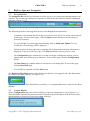
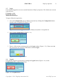
Flagship Automation Ltd. DQCsys Operator User Manual Revision 1.21 For DQCsys Operator Revision 12.00 January 6, 2011 www.DQCsys.com Copyrights © 2011 Flagship Automation Ltd. www.DQCsys.com DQCsys Operator User Manual Revision 1.21 i Document Revision Table Revision Description 1.00 Initial Release 1.10 Major content changes to the following sections: - Section 1: DQCsys Operator Navigation - Section 2:Configuration - Section 7: Process Alarms Updated pictures of the User Interface Improvements 1.20 Updated for Revision 12.00: - Section 2.5: Notes added on Recipe Designation Name - Section 2.6: Notes added on Recipe Precision - Section 4&5: Notes added on Recipe Change Log and Record Display - Section 8: Updated for the new webserver Updated pictures of the User Interface changes 1.21 Changes include: - Section 1: Update to reflect User Interface changes - Section 5: Updated to reflect User Interface changes - Section 7: Updated the alarm color scheme - Section 8.6: Custom Logo Section added Additional minor corrections were made Copyrights © 2011 Flagship Automation Ltd. Date June 11, 2011 September 7, 2011 December 23, 2011 January 6, 2012 www.DQCsys.com DQCsys Operator User Manual Revision 1.21 ii Table of Contents Introduction ......................................................................................................................................... iv DQCsys Operator Requirements ......................................................................................................... iv 1 DQCsys Operator Navigation ...................................................................................................... 1 1.1 Header Section .................................................................... Error! Bookmark not defined. 1.1.1 Header Information ............................................................................................................. 1 1.1.2 Navigation Bar .................................................................. Error! Bookmark not defined. 2 1.2 Login ..................................................................................................................................... 2 1.3 Logout ................................................................................................................................... 2 Configuration ............................................................................................................................... 3 2.1 Accessing DQCsys Configuration Window .......................................................................... 3 2.2 DQCsys Configuration Window Navigation ......................................................................... 4 2.3 Database Connections Page................................................................................................... 4 2.3.1 Database Statuses ........................................................................................................... 5 2.3.2 Test and Save Database Connections ............................................................................. 5 2.2.3 SQL Server Communication Settings ............................................................................ 6 2.4 Users Page ............................................................................................................................. 6 2.4.1 User Access Level .......................................................................................................... 6 2.4.2 Find User ........................................................................................................................ 6 2.4.3 User Creation ................................................................................................................. 7 2.4.4 Edit Users ....................................................................................................................... 7 2.4.5 User Deletion ................................................................................................................. 7 2.5 Setup Information Page ......................................................................................................... 8 2.5.1 2.6 4 Processes Page ....................................................................................................................... 9 2.6.1 Find Process ................................................................................................................... 9 2.6.2 New Process ................................................................................................................... 9 2.6.4 Delete Process ................................................................................................................ 9 2.7 3 Edit Setup Information .................................................................................................. 8 Recipe Fields Page .............................................................................................................. 10 2.7.1 New Recipe Field ......................................................................................................... 10 2.7.2 Edit Recipe Field .......................................................................................................... 11 Process Specification ................................................................................................................. 12 3.1 Specification Settings .......................................................................................................... 12 3.2 Parameters Details ............................................................................................................... 13 The Recipe Database ................................................................................................................. 14 4.1 Accessing Recipe Database ................................................................................................. 14 4.2 Select Recipe ....................................................................................................................... 15 4.3 Find Recipe.......................................................................................................................... 15 Copyrights © 2011 Flagship Automation Ltd. www.DQCsys.com DQCsys Operator User Manual Revision 1.21 4.4 New Recipe ......................................................................................................................... 15 4.5 Copy Recipe ........................................................................................................................ 15 4.6 Rename Recipe .................................................................................................................... 16 4.7 Edit Each Process Parameter Values ................................................................................... 16 4.8 Recipe Record Display ........................................................................................................ 17 4.9 Edit Recipe Info................................................................................................................... 17 4.10 5 6 7 8 iii Load Recipe into Manage Recipe Window ..................................................................... 18 Further Recipe Management ...................................................................................................... 19 5.1 Edit Recipe Data .................................................................................................................. 19 5.2 Save Recipe Data................................................................................................................. 19 5.3 Recipe Auto Update............................................................................................................. 20 5.4 Recipe Record Display ........................................................................................................ 20 5.5 Load Recipe into DQCsys Operator .................................................................................... 20 5.6 Update Process Controls ..................................................................................................... 21 5.7 Update All Process Controls................................................................................................ 21 The Process Page ....................................................................................................................... 22 7-1 Enabling a Process............................................................................................................... 22 6.2 Clear a Specific Process ...................................................................................................... 23 7-3 Clear All Processes .............................................................................................................. 23 Process Alarms ........................................................................................................................... 24 7.1 Global Alarms...................................................................................................................... 24 7.2 Specific Alarms ................................................................................................................... 24 7.2.1 X-Bar Specification Alarm.......................................................................................... 25 7.2.2 X-Bar Control Limit..................................................................................................... 25 7.2.3 Range Control Limit .................................................................................................... 25 7.3 Alarm Log ........................................................................................................................... 26 7.4 Reset Alarms........................................................................................................................ 26 7.5 Reset All Alarms .................................................................................................................. 26 Web Server ................................................................................................................................. 27 8.1 Requirements ........................................................................................................................... 27 8.1.1 Opening Ports on Windows Firewall ................................................................................ 27 8.2 How to View Remotely ............................................................................................................ 31 8.3 WebStation Main Page ............................................................................................................. 31 8.4 Process Webpage ...................................................................................................................... 32 8.5 Auto Update ............................................................................................................................. 32 8.6 Custom Logo ............................................................................................................................ 32 Copyrights © 2011 Flagship Automation Ltd. www.DQCsys.com DQCsys Operator User Manual Revision 1.21 iv Introduction Welcome to DQCsys Operator User Manual. This manual will cover the features and usage of DQCsys Operator, software designed for distributed quality control systems. However, it does not cover the installation and first-time configuration, Please see DQCsys Operator Quick Start Guide to get started on using DQCsys Operator. DQCsys Operator Requirements The following sections list the requirements to run DQCsys Operator. A Flagship Protection Key is required to run the full version of DQCsys Operator. Contact us at [email protected] to acquire a key. Please note that the DEMO version will exit automatically after 10 minutes of run time. Software Requirements The following listed software is available free to download and is required for DQCsys Operator to run properly. HASP Driver is the driver used for the protection key. It must be installed on every computer that the protection key is used. Microsoft SQL Server Express Edition is the program the DQCsys system uses to store information. The server must be configured for SQL Server Authentication. LabVIEW Run-Time Engine 2010 is required to be installed on computers that will be remotely accessing DQCsys Operator. See 9 Remote Access for more details on this feature. System Requirements The hardware requirements for the supported operating systems, Windows XP Pro SP3 and Windows 7 Pro, are listed below. Operating System: Windows XP Pro SP3 CPU Required: 1.5 GHz or faster Memory Required: 1 GB RAM or higher required Monitor Required: 1280x1024 capable monitor Installation and Operation: 4G or higher free hard drive space required Operating System: Windows 7 Pro CPU Required: 1.5 GHz or faster Memory Required: 2 GB RAM or higher required Monitor Required: 1280x1024 capable monitor Installation and Operation: 4G or higher free hard drive space required Copyrights © 2011 Flagship Automation Ltd. www.DQCsys.com CHAPTER 1 1 DQCsys Operator Navigation 1.1 Navigation Bar DQCsys Operator 1 The Navigation Bar on DQCsys Operator provides access to its various pages through buttons and selectors. The current page displayed on Operator is indicated by the button or selector highlight in light blue. (Figure 1.1-1) Figure 1.1-1: DQCsys Operator’s Navigation Bar The following describes each page that can be access through the navigation bar. - A summary of all plotted data for each process can be viewed in five at a time when selected a main page. To access these pages, click the Main selector and then select the group of processes of interest. - To cycle through every main page automatically, click on Main Auto Update. Every 4 second, the next main page will be displayed. - Each process has its own page where incoming data is plotted and statistical information is displayed. To access a process’s page, click Process and then select a process’s page. - The Configuration page contains access to the user login, configuration options, project management, and various process functions. To access this page, click the Configuration button - The Raw Data page contains tables of each process’s incoming data. To access this page, click the Raw Data page. - To exit DQCsys Operator, click the Exit button. The Database Write Fault alarm is also displayed on this bar. It is triggered red when data cannot be written to the Data database, see figure 1.1-2. Figure 1.1-2: Database Write Fault Alarm, currently green indicating data can be written to the Data database. 1.2 Version Display On the Configuration page, the version of DQCsys Operator is displayed as seen in Figure 1.2.-1. This information includes the current revision of Operator, the serial number of the Protection Key, and the number of processes licenced according to the key. Figure 1.2-1: Database Write Fault Alarm Copyrights © 2011 Flagship Automation Ltd. www.DQCsys.com CHAPTER 1 1.3 DQCsys Operator 2 Login Users must be logged in to access essential functions of DQCsys Operator. The default user account is given below: Username: Admin Password: flagship Access Level: Manager To login, follow the steps below: 1. Go to the Configuration page on DQCsys Operator by clicking the Configuration button located on the navigation bar (Figure 1.3-1). Figure 1.2-1: The Configuration button on DQCsys Operator’s navigation bar. 2. Next, click the Login button, (Figure 1.3-1). Figure 1.3-1: The Login Button. 3. Enter a valid username and password on the Login window (Figure 1.3-2). Please note that the password is case sensitive. When done, click the Login Figure 1.3-2: The Login Window 1.4 Logout Users that are logged in can logout by clicking the Logout button (Figure 1.4-1) on the Configuration page of DQCsys Operator. Figure 1.4-1: Logout Button Copyrights © 2011 Flagship Automation Ltd. www.DQCsys.com CHAPTER 2 2 Configuration 3 Configuration DQCsys Operator can be configured by the database connections, the setup information, and the processes. This is the location where new processes can be added. Users must have an access level of a Manager to configure DQCsys Operator. 2.1 Accessing DQCsys Configuration Window The DQCsys Configuration window allows configuration of database connection, setup information, and processes. This window can be accessed by the following steps. 1. Login to an authorized user account. See 1.2 Login for more details. 2. Click the Configuration button on the Configuration tab of DQCsys Operator. (Figure 2.11) Figure 2.1.1: The Manage User and Configuration buttons. 3. A popup appears warning that continuing may reinitialize the program. Click OK. 4. The DQC Configuration window will appear.(Figure 2.1-2) Figure 2.1-2: The DQC Configuration window Copyrights © 2011 Flagship Automation Ltd. www.DQCsys.com CHAPTER 2 2.2 Configuration 4 DQCsys Configuration Window Navigation There are five steps in DQC Configuration. They are the Database Connection, Users, Setup Information, Processes, and Project Fields steps. Each step has its own page which can be accessed by the Steps side bar (Figure 2.2-1). Figure 2.2-1: The Steps side bar The steps that are enabled have a green circle adjacent to their label. In order to enable the next step, the current step must be completed successfully. The next or previous page can also be accessed by clicking the Next or Back buttons located at the bottom of DQC Configuration window. (Figure 2.2-2) Figure 2.2-2: Back, Next, and Exit buttons Clicking Exit will close the window if all the steps are enabled. If not, a message will appear indicating that the configuration must be completed. However, the option to exit DQCsys Operator is given. Note: Any changes made in the DQCsys Configuration will restart DQCsys Operator. 2.3 Database Connections Page DQCsys Operator uses four databases to save process data, recipes, setup configuration, and its internal user system. Each connection to a database can be configured on the Database Connections page of the DQC Configuration window. (Figure 2.3-1) Figure 2.3-1: Database Connections page Copyrights © 2011 Flagship Automation Ltd. www.DQCsys.com CHAPTER 2 Configuration 5 2.3.1 Database Statuses The Database Connection Information table list-box displays the Server Path, SQL Username and Status of each database connection. Each status is explained below: Missing: Failed: Passed: Indicates that the connection to the database does not exist. Indicates that the connection to the database has failed. Indicates that the connection to the database has passed. 2.3.2 Test and Save Database Connections DQCsys Operator uses data link files (.UDL) to connect to each database. The following steps describe how to test and save each database connection individually on the Database Connections page. 1. First select a database by clicking its row on the Database Connection Information table. (Figure 2.3.2-1) The selected database’s row is highlighted in blue. Figure 2.3.2-1: The Recipe Database is selected 2. Enter a valid Server Path, SQL User name, and Password. The server path is the address of the SQL Server. If the server does not already contain the selected database, it will be automatically created. Note: The common format for the server path is the following: the name of the computer that has the SQL Express Server, followed by a backslash “\” and then, the SQL server name which is usually ‘SQLEXPRESS”. Warning: Please see DQCsys Operator Quick Start-up Guide for the proper setup of the SQL Server. 3. Make sure that the Use same connection information for all databases checkbox is unchecked. (Figure 2.3.2-2) Figure 2.3.2-2: The Use same connection information for all databases checkbox is unchecked. Note: When using a single server to contain all four databases, the connection information for each database will be the same. For convenience, check on the Use same connection information for all databases checkbox. All the database connections can now be tested or saved using the same inputted Server Path, SQL Username, and Password. 4. Click the Save button to save any changes made or the Test button to check that the connection information is correct before making any permanent changes. Copyrights © 2011 Flagship Automation Ltd. www.DQCsys.com CHAPTER 2 Configuration 6 2.2.3 SQL Server Communication Settings Depending on the location of the SQL Server that is being connected to, the Write Delay and Connection Timeout may need to be adjusted. (Figure 2.3.3-1) Figure 2.3.3-1: SQL Server Communication Settings The Write Delay is the number of seconds before the data obtained from each processes is sent to the SQL Server. The default value is 30 seconds. This value may be adjusted according to how frequently DQCsys Operator obtains data from each process. The Connection Timeout is the number of seconds before the attempt to connect to the SQL Server fails. The default value is 5 seconds. When connecting to remove servers, this value may need to be increased. 2.4 Users Page DQCsys Operator uses an internal user system to regulate accesses to the configuration options. The user accounts can be modified in the User page of the DQCsys Configuration window. To access this page, click on Users on the Steps side bar. This page is only accessible once all the database connections have passed. (Figure 2.4-1) Figure 2.4-1: The Users Page Note: For the description of each Access Level, please see 2.4.1 User Access Level. 2.4.1 User Access Level The amount of features that can be accessed by a user account is specified by one of the three access levels listed below Operator: limited to finding and loading recipe from the database. Supervisor: has access to full recipe functions. Manager: has access to full recipe functions, user management, and DQCsys Operator configuration. 2.4.2 Find User To search for a user, click Find User. A dialog will appear asking to enter the username to search. When done, click OK. Then, the username will be selected on the User Database table if it was found. Copyrights © 2011 Flagship Automation Ltd. www.DQCsys.com CHAPTER 2 Configuration 7 2.4.3 User Creation New users can be created by clicking the New User button. The Create a New User window will appear. Enter the user’s information to the appropriate fields. When finished, click OK. (Figure 2.4.3-1) Figure 2.4-3: The Create a New User Window 2.4.4 Edit Users User’s account information can be edited by the following steps: 1. Select a user by clicking on its username in the User Database table. (Figure 3.4-1) The selected user will be highlighted blue. 2. Click Edit User to open the Edit User window. The Access Level, First Name, Last Name, and Password field can be added. Note: There must be at least one manager account at all times. When editing the only manager, the Access Level cannot be changed. 2.4.5 User Deletion Unwanted Users can be by the following steps: 1. Select a user by clicking on its username in the User Database table. (Figure 3.4-1) The selected user will be highlighted blue. 1. A confirmation window will appear. Click the Delete button to proceed. Warning: Deleting a user is permanent. Copyrights © 2011 Flagship Automation Ltd. www.DQCsys.com CHAPTER 2 2.5 Configuration 8 Setup Information Page Each machine is distinguished between other machines by its Setup Information. This information contains the Division, Factory, Machine Tag, Machine’s Serial Number, the Machine's Full Name, and the Recipe Designation. The Setup Information can be modified on the Setup Information page of the DQC Configuration window. To access this page, click on Setup Information on the Steps side bar. This page is accessible once all the database connections have passed. (Figure 2.5-1) Figure 2.5-1: The Setup Information Page. 2.5.1 Edit Setup Information To edit the machine’s Setup Information, click Edit Setup Information. The Edit Setup Information window will appear. (Figure 2.5.1-1) When done, click OK to save the Setup Information. Note: The Recipe Designation Name specifies how recipes will be called. In this manual, the recipe designation name used will be project. The Machine Tag field will be automatically generated. Figure 2.5.1-1: The Edit Setup Information Configuration Window Copyrights © 2011 Flagship Automation Ltd. www.DQCsys.com CHAPTER 2 2.6 Configuration 9 Processes Page DQCsys Operator’s data processing is structured by processes. Each process has its own individual stream of incoming data, plots, statistical computation, recipe and alarms. Processes can be added, renamed, and deleted on the Process page on the DQCsys Configuration window. To access this page, click on Process on the Setups side bar of the window. This page is only accessible once all the database connections have passed and the Setup Information has been filled. The Process List table displays each process’s number, name, the number of data records stored in the process’s table in the Data database, and the recipe precision. The recipe precision indicates the number of decimals used for the process’s parameters in each recipe. The selected process has its row highlighted blue. (Figure 2.6-1) Figure 2.6-1: The Processes Section on the DQC Configuration Window 2.6.1 Find Process To search for a process, click Find User. A dialog will appear asking to enter the name of the process to search. When done, click OK. Then, the Process will be selected on the Process List table if it was found. 2.6.2 New Process To add a new Process, click New Process. The Add New Process window will appear. Enter the Process Name and the Recipe Precision and click OK. The recipe precision indicates the number of decimal places used for the process’s parameters in each recipe. For instance, a recipe precision of 2 will allow that process’s control limit in the recipe to be set to 10.54. Note: The highest recipe precision that can be set is 3. The maximum number of process that can be added depends on the licence used. 2.6.3 Edit Process To edit a process, first select it by clicking its row on the Process List table. Next, click Edit and make the necessary changes on the Rename Process window. When done, click OK. Warning: Be sure that the changes made to the name of the process are still relevant to any pre-existing data currently stored in that process. This would avoid confusion later when viewing this data. 2.6.4 Delete Process To delete a process, first select it by clicking its row on the Process List table can be deleted by the following steps. Next, click the Delete Process button. On the Delete Process window, enter “DELETE” in the field and click OK to confirm. Warning: Deleting a process will permanently remove all data records and process’s recipes. Copyrights © 2011 Flagship Automation Ltd. www.DQCsys.com CHAPTER 2 2.7 Configuration 10 Recipe Fields Page Recipe Fields are custom fields that specify addition information about each Recipe. Recipe also contains each process’s own recipe which specifies how incoming data will be processed. Recipe Fields can be only added or modified on the Recipe Fields page on the DQCsys Configuration window. To access this page, click on Recipe Fields on the Steps side bar of the window. This page is only accessible once all the database connections have passed and the Setup Information has been filled. The Recipe Fields List table displays each recipe field’s number, name, type, and status. There are 10 available recipe fields that can be used. The three types a Recipe Field can be are a string/text field, a selector field, a number field. (Figure 2.7-1) Figure 2.7-1: The Recipe Fields page 2.7.1 New Recipe Field To create a new Recipe Field, click New Field. On the New – Recipe Field window the field’s name can be entered and the field’s type can be chosen. If the selector field type is chosen, the Selector Items list-box will appear. To add new items, click Add Item. Enter the new item’s name and click OK. Newly added items will be highlighted in light blue. (Figure 2.7.1-1) The Field Preview provides a preview of how the field will behave. When done, click OK. Warning: Once the Project Field is created, the field type cannot be changed and any selector items cannot be modified or removed. Figure 2.7.1-1: The New – Recipe Field Window Copyrights © 2011 Flagship Automation Ltd. www.DQCsys.com CHAPTER 2 Configuration 11 2.7.2 Edit Recipe Field To edit a Recipe Field, first select it by clicking its row on the Process List table. Next, click Edit Field. On the Edit – Recipe Field, the field’s name can be changed. New items can be added if the field is a selector by clicking Add Item. Enter the new item’s name and click OK. Newly added items will be highlighted in light blue. The Field Preview provides a preview of how the field will behave. When done, click OK. Copyrights © 2011 Flagship Automation Ltd. www.DQCsys.com CHAPTER 3 3 Process Specification 12 Process Specification DQCsys Operator allows customization of process parameters and specifications which is organized in what are called Recipes. 3.1 Specification Settings Each process specification has two modes: the Fixed Controls or Delta Controls modes. This option affects the following specification parameters: Upper Spec., X-Bar UCL, X-Bar LCL, and Lower Spec. Fixed Controls: The actual values for Upper Spec., X-Bar UCL, X-Bar LCL, and Lower Spec are independent from X-bar CL. These values are static. Delta Controls: The actual values for Upper Spec., X-Bar UCL, X-Bar LCL, and Lower Spec are dependent of Xbar CL. The entered values for the affected controls are the amount of change the actual desired value differs with X-bar CL. For example, If Upper Spec. has a value of 25 and X-bar CL has a value of 25, the actual Upper Spec value is 25 + 25 = 50. See Figure 3.1-1. Figure 3.1-1: Process 1 and Process 2 Controls result in the same values but different use different settings. Copyrights © 2011 Flagship Automation Ltd. www.DQCsys.com CHAPTER 3 3.2 Process Specification 13 Parameters Details The following describes each parameters of a process speciation: Parameter Upper Spec. (US) Lower Spec. (LS) X-Bar UCL X-Bar CL X-Bar LCL Range UCL Range CL Range LCL # of Sample SPP # of Bars Full Name Upper Speciation Lower Speciation X-Bar Upper Control Limit X-Bar Control Limit X-Bar Lower Control Limit Range Upper Control Limit Range Control Limit Range Lower Control Limit Total number of Samples Samples per Point Number of Bars Copyrights © 2011 Flagship Automation Ltd. Applies to… X-Bar & Histogram Chart X-Bar & Histogram Chart X-Bar Chart X-Bar Chart X-Bar Chart Range Chart Range Chart Range Chart Histogram Chart X-Bar & Range Chart Histogram Chart www.DQCsys.com CHAPTER 4 4 The Recipe Database 14 The Recipe Database DQCsys Operator uses a database to store different configurations of each process’s parameters. These are organized in recipe which contain a global set of information that apply to all processes. 4.1 Accessing Recipe Database The Access Recipe Database window allows to manage recipes and to edit the each of the recipe’s parameters. This window can be accessed by the following steps: 1. Login to a user account with manager or supervisor privileges. See section 1.2 Login for more details. 2. Click the Access Recipe button on the Configuration tab of DQCsys Operator. The Manage Recipe window (Figure 4.1-1) will appear. For details on this window, see 6 Manage Recipe. Figure 4.1-1: The Manage Recipe Window 3. Click the Access Database button. The Access Recipe Database window will appear. (Figure 4.1-2) Figure 4.1-2: The Access Recipe Database Window: The “Test” recipe is currently selected. Copyrights © 2011 Flagship Automation Ltd. www.DQCsys.com CHAPTER 4 4.2 The Recipe Database 15 Select Recipe Recipes are listed in the centred list-box in the Access Recipe Database window. They can be selected by clicking on a recipe’s name from the Recipe List-box (Figure 4.2-1). The selected recipe is highlighted in blue. Figure 4.2-1: The Recipe List-box: The “Test” Recipe is selected. 4.3 Find Recipe Recipes can be searched for in the Access Recipe Database window by the following steps: 1. Click the Find button on the Access Recipe Database window. (Figure 4.1-2) The Enter Recipe popup will appear. 2. Enter the recipe’s name to search for in the Enter Recipe popup. Click Find to continue. 3. If the recipe exists, it will be automatically selected in the Recipe List-box. 4.4 New Recipe New recipes can be created in the Access Recipe Database window by the following steps: Note: when renaming a process, the Recipe Data/Time field will be updated (Figure 4.8-1). 1. Click the New button on the Access Recipe Database window. (Figure 4.1-2) The Create New Recipe popup will appear. 2. Enter a unique recipe name in the Create New Recipe popup. Click Create Recipe to continue. 3. A popup will indicate if the recipe was created successful. The new recipe will also appear in the Recipe List-box. 4.5 Copy Recipe Recipes can be duplicated in the Access Recipe Database window by following the procedure below: 1. Select the desired recipe from the Recipe List-box on Access Recipe Database window. (Figure 4.2-1) See 4.2 Select Recipe for more details. 2. Click the Copy button on the Access Recipe Database window. (Figure 4.1-2) Enter New Recipe Name popup will appear. 3. Enter a new unique recipe name in the Enter Recipe popup. Click OK to continue. 4. A popup will indicate if the recipe was copied successful. The copied recipe will also appear in the Recipe list-box. Copyrights © 2011 Flagship Automation Ltd. www.DQCsys.com CHAPTER 4 4.6 The Recipe Database 16 Rename Recipe Recipes can be renamed in the Access Recipe Database window by following the procedure below: 1. Select the desired recipe from the Recipe List-box on Access Recipe Database window. (Figure 4.2-1) See 4.2 Select Recipe for more details. 2. Click the Rename button on the Access Recipe Database window. (Figure 4.1-2) The Enter Recipe Name popup will appear. 3. Enter a new unique recipe name in the Enter Recipe Name popup. Click OK to continue. 4. A popup will indicate if the recipe was renamed successful. The recipe’s name in the Recipe list-box will also be updated. 4.7 Edit Each Process Parameter Values Each process parameter can be edited in the Access Recipe Database window by the following steps: 1. Select the desired recipe from the Recipe List-box on Access Recipe Database window. (Figure 4.2-1) See 4.2 Select Recipe for more details. 2. Click on a parameter value on the multi-column list-box in the Access Recipe Database window. (Figure 4.7-1) Enter new value for that parameter and click on anywhere other than parameter. Figure 4.7-1: The Multi-Column List-Box: Process 1 X-Bar UCL is being edited. Note: Press the Enter or the Down keys to edit the next parameter. Press the Up key to edit the previous parameter. 3. Repeat this process for any other parameter. Once complete, click Save to save all changes made to the recipe. (Figure 4.7-3) Figure 4.7-3: The Save button. 4. The Recipe Change Log dialog will then appear. Enter the reason for the change and click OK. By not entering any reason, an error message will appear, click OK and once again click OK to finish without entering any reason. 5. The Recipe Revision and Comments will be updated (Figure 4.8-1). Copyrights © 2011 Flagship Automation Ltd. www.DQCsys.com CHAPTER 4 4.8 The Recipe Database 17 Recipe Record Display The Recipe Record Display as shown in figure 4.8-1 indicates the creation date/time of the recipe, its latest revision number, who created the recipe, and the latest recipe comments of the current selected recipe. Figure 4.8-1: The Recipe Record Display. 4.9 Edit Recipe Info The Recipe Info can be edited on the Recipe Info column (Figure 4.9-1) after changes are made, click Save to save them. (Figure 4.7-3) To configure the fields used by the Recipe Info column, see 2.7 Recipe Fields Page. Figure 4.9-1: The Recipe Info Column Copyrights © 2011 Flagship Automation Ltd. www.DQCsys.com CHAPTER 4 The Recipe Database 18 4.10 Load Recipe into Manage Recipe Window The selected recipe can be loaded into the Manage Recipe window from the Access Recipe Database window by the following steps: Please note that the recipe can then be directly loaded into DQCsys Operator by clicking on the Load button on Manage Recipe window (Figure 4.10-1). 1. Select a recipe from the Recipe List-box on Access Recipe Database window. (Figure 4.21) See 4.2 Select Recipe for more details. 2. Click OK. The selected recipe is loaded into the Manage Recipe window (Figure 4.10-1) . Figure 4.10-1: The Manage Recipe Window: The Test Recipe Loaded Copyrights © 2011 Flagship Automation Ltd. www.DQCsys.com CHAPTER 5 5 Further Recipe Management 19 Further Recipe Management DQCsys Operator provides an alternate layout for editing recipes using the Manage Recipe window. Process Parameters can be also trimmed without necessarily updating the changes to the database. See 5 The Recipe Database for accessing and loading a recipe to the Manage Recipe window. (Figure 6-1) Figure 6-1: The Manage Recipe Window 5.1 Edit Recipe Data The recipe information and process specification can be changed on the Manage Recipe window. To change the recipe settings, click on the combo box located below the title of each process’s module and select the recipe setting. (Figure 5.1-1) See 3.1 Specification Settings for details on the recipe setting behaviours. Figure 5.1-1: Change Specification Setting 5.2 Save Recipe Data The loaded recipe data on the Manage Recipe window can be saved after being edited by clicking the Save button (Figure 5.2-1). A confirmation popup will appear, click OK to save. Figure 5.2-1: The Save button on the Manage Recipe window. The Recipe Change Log dialog will then appear. Enter the reason for the change and click OK. By not entering any reason, an error message will appear, click OK and once again click OK to finish without entering any reason. The Recipe Revision and Comments will be updated (Figure 5.4-1). Copyrights © 2011 Flagship Automation Ltd. www.DQCsys.com CHAPTER 5 5.3 Further Recipe Management 20 Recipe Auto Update The behaviour of how recipes are loaded from the Manage Recipe window into DQCsys Operator, through the Recipe Auto Update checkbox (Figure 5.3.1) on the Manage Recipe window. Enabling this feature will automatically update the specification of each process’s plots when a recipe is loaded to the DQCsys Operator. Figure 5.3.1: The Recipe Auto Update Checkbox 5.4 Recipe Record Display The Recipe Record Display as shown in figure 5.4-1 indicates the creation date/time of the recipe, its latest revision number, who created the recipe, and the latest recipe comments of the current selected recipe. This display is also visible on the Configuration page of DQCsys Operator. Figure 5.4-1: The Recipe Record Display. 5.5 Load Recipe into DQCsys Operator Recipes can be loaded from the Manage Recipe window into DQCsys Operator by the following steps: 1. Click the Load button on the Manage Recipe window. (Figure 5.5-1) Figure 5.5-1: The Load Button. 2. The Manage Recipe window will close and the recipe is loaded into DQCsys Operator (Figure 5.5-2) Figure 5.5-2: The Configuration page of DQCsys Operator Copyrights © 2011 Flagship Automation Ltd. www.DQCsys.com CHAPTER 5 5.6 Further Recipe Management 21 Update Process Controls To update a specific process’s graph control after making changes to its recipes, click the corresponding Update button (Figure 5.6-1) located on the Configuration tab of DQCsys Operator Figure 5.6-1: The Update Button for Process 1 Controls. The current process’s graph controls are displayed on the tab labelled by the process’s name. See Figure 5.6-2. Figure 5.6-2: The X-Bar Chart Controls on Process 1 tab 5.7 Update All Process Controls To update every process’s graph control simultaneously after making changes to the loaded recipe, click the Update All button on the Configuration tab of DQCsys Operator. (Figure 5.7-1) Figure 5.7-1: The Update All Button for Process 1 Controls. Copyrights © 2011 Flagship Automation Ltd. www.DQCsys.com CHAPTER 6 6 The Process Page 22 The Process Page The Process Page (Figure 6-1) monitors and analyses incoming data for a particular process. To access a process’s page, click the tab labelled by the name of the corresponding process on DQCsys Operator. Figure 6-1: The Process Page for “Process 1”. 7-1 Enabling a Process The On/Off button on each process’s tab on DQCsys Operator enables or disables a process. If this button is labelled “ON”, the process is currently enabled. (Figure 6.1-1) When a process is enabled, DQCsys Operator will then accept incoming process data. Figure 6.1-1: The On/Off Button All Process can be turned on or off by clicking the All ON or All OFF on the Configuration page. (Figure 6.1-2) Figure 6.1-2: The All ON and All OFF Buttons Copyrights © 2011 Flagship Automation Ltd. www.DQCsys.com CHAPTER 6 6.2 The Process Page 23 Clear a Specific Process To clear the data displayed on a particular process’s charts and alarms, click the Clear button (Figure 6.2-1) on the corresponding process’s tab. A confirmation popup will appear. Click OK. Figure 6.2-1: The Clear Button 7-3 Clear All Processes To clear the data displayed on all process’s charts and alarms, click the yellow All button (Figure 6.3-1) located next to the Clear button on any process tab. A confirmation popup will appear. Click OK. This can also be done on the Configuration page by clicking Clear All button. (Figure 6.3-2) Figure 6.3-1: The Yellow All Button. Figure 6.3-2: The Clear All Button Copyrights © 2011 Flagship Automation Ltd. www.DQCsys.com CHAPTER 7 7 Process Alarms 24 Process Alarms Alarms provide a real-time feedback whether the incoming data into DQCsys Operator exceed the specifications of the recipe. Each process has four alarms: General, X-bar Specification, X-bar CL Limit, and Range CL Limit. 7.1 Global Alarms Each process’s global alarm can be accessed on any process page by clicking Global Alarms. (Figure 7.1-1) A process’s global alarm is triggered when one of its specific alarms have been also triggered. If only the X-bar CL Limit Alarm triggered, the global alarm will be yellow. If X-bar Specification Alarm and or Range CL Limit Alarm are either triggered, the global alarm will be red. Figure 7.1-1: The Global Alarms button. Figure 7.1-2: The Process 7.2 Specific Alarms A process’s specific alarms are visible on the Main page or (Figure 7.2-1) the process’s own page (Figure 7.2.1-1). Figure 7.2-1 Process 1’s specific alarms; X-bar Specification, X-bar CL Limit, and Range CL Limit Alarms on the Main tab. Copyrights © 2011 Flagship Automation Ltd. www.DQCsys.com CHAPTER 7 Process Alarms 25 7.2.1 X-Bar Specification Alarm The X-Bar Specification Alarm is triggered red if a point on the X-Bar chart is outside the Upper and Lower Specification. The point that triggered this alarm is coloured red on the X-bar/I-MR Chart. 7.2.2 X-Bar Control Limit The X-Bar Control Limit Alarm is triggered yellow if a point on the X-Bar chart is outside the Upper and Lower Control Limits. The point that triggered this alarm is coloured yellow on the Xbar/I-MR Chart. (Figure 7.2.1-1) Figure 7.2.1-1: The Control Limit Alarms is triggered. 7.2.3 Range Control Limit The Range Control Limit Alarm is triggered red if a point on the Range chart is outside the Upper and Lower Control Limits. The point that triggered this alarm is coloured red on the Range Chart. (Figure 7.2.3-1) Figure 7.2.3-1: Range Control Limit is triggered. Copyrights © 2011 Flagship Automation Ltd. www.DQCsys.com CHAPTER 7 7.3 Process Alarms 26 Alarm Log Each process’s alarm log is displayed on their own process page. To view a process’s alarm log, click the Alarm Log on that process’s page. (Figure 7.3-1)] Figure 7.3-1: The Alarm Log button A Process’s Alarm Log provides a more detailed presentation of an activated alarm. It includes the data point number where the alarm has been triggered on the X-bar and Range Charts. Process shifts are also indicated on the Alarm Log. (Figure 7.3-2) Figure 7.3-2: The Alarm Log field 7.4 Reset Alarms To reset a specific process’s alarms, click the Reset Button (Figure 7.4-1) on the corresponding process’s tab. Figure 7.4-1: The Reset Button. 7.5 Reset All Alarms To reset the alarms of every process simultaneously, click the green All button (Figure 7.5-1) located next to the Reset button on any process tab. This can also be done on the Configuration page by clicking Reset All button. (Figure 7.5-2) Figure 7.5-1: The Green All Button. Figure 7.5-2: The Rest All Button Copyrights © 2011 Flagship Automation Ltd. www.DQCsys.com CHAPTER 8 8 Web Server 27 Web Server The data processed by DQCsys Operator can be view remotely through the web browser. This section will describe how to use this feature. 8.1 Requirements The following lists the requirements to allow others to view the data being processed by Operator using their web browser. Both computers, the one running and the one viewing DQCsys Operator, must be connected to the same network. The computer name or the IP address of the computer running Operator must be known by the person viewing Operator remotely. DQCsys Operator must be currently running. The firewall of the computer running Operator must have port 80 opened. Check Windows Firewall as it is most commonly used. For troubleshooting purposes, you may want to turn firewall temporarily. 8.1.1 Opening Ports on Windows Firewall This section will guide you on opening port 80 in Windows Firewall on Windows XP Pro SP3 and Windows 7 Pro if you wish to allow other computers accessed the data being processed by Operator through the web browser. The following steps will guide you in opening a port in Windows XP Pro SP3: 1. Click the Start button. Then click Control Panel on the start menu. (Figure 8.1.1-1) Figure 8.1.1-1: Accessing the Control Panel Window Copyrights © 2011 Flagship Automation Ltd. www.DQCsys.com CHAPTER 8 Web Server 28 2. The Control Panel window will appear. Make sure the Control Panel is set to Classical View. Scroll to find and click on the Windows Firewall icon and text. Figure 8.1.1-2: Accessing the Windows Firewall button. 3. The Windows Firewall window (Figure 8.1.1-3) will appear. Make sure the On option is selected and the Don’t allow exceptions checkbox is not checked. Then, click the Exceptions tab. Please note: For troubleshooting purposes, to turn the firewall off is an option. Just, select the Off option and click OK. Figure 8.1.1-3: The Windows Firewall window Copyrights © 2011 Flagship Automation Ltd. www.DQCsys.com CHAPTER 8 Web Server 29 4. Click the Add Port… button on the Exceptions tab of the Windows Firewall window. The Add a Port window (Figure 8.1.1-4) will appear. Enter the following information and click OK: Name: DQCsys Operator Web Server Port number: 80 Figure 8.1.1-4: The Add a Port Window. 5. On the Windows Firewall window, click OK. The following steps will guide you in opening a port in Windows 7 Pro: 1. Click the Start Button and search for Windows Firewall on the Start Menu’s search bar. The Windows Firewall with Advanced Security item will appear. Click it. (Figure 8.1.1-5) Figure 8.1.1-5: Accessing Windows Firewall with Advanced Security window. 2. Click on Inbound Rules and then right click and select New Rule… (Figure 8.1.1- 6) Copyrights © 2011 Flagship Automation Ltd. www.DQCsys.com CHAPTER 8 Web Server 30 Figure 8.1.1-6: Accessing New Inbound Rules Wizard. 3. The New Inbound Rules Wizard appears, select Port (Figure 8.1.1-6) and then click Next on the New Inbound Rules Wizard. Figure 8.1.1-6: Selecting Port on the New Inbound Rules Wizard 4. Then select Specific local ports, and then enter “80” (Figure 8.1.1-7). When finished, click Next. Figure 8.1.1-7: Select Specific local ports. 5. Continue clicking Next on the New Inbound Rules Wizard window. On the last step of the wizard, enter “DQCsys Operator Web Server” as the name of this inbound rule and click Finished. Copyrights © 2011 Flagship Automation Ltd. www.DQCsys.com CHAPTER 8 Web Server 31 8.2 How to View Remotely The following steps will guide you in accessing DQCsys Operator remotely. Before starting, be sure to meet the requirements on 8.1 Requirements. 1. Open your web browser of your choice. Windows Internet Explorer will be used in this example. 2. Go to one of the following address below replacing COMPUTER with either the computer name or IP address of the machine running DQCsys Operator. (Figure 8.21) http://COMPUTER http://COMPUTER:80 http://COMPUTER/index.html Figure 8.2-1: Example address where the computer running DQCsys Operator has the IP address: 192.168.1.135 8.3 WebStation Main Page On the main webpage, scroll down to view each a summary of each process which includes the Xbar Chart, Histogram, Process Status and Alarms. To quickly go to a process’s summary; click the process’s name in the Station Status table as seen in Figure 8.3-1. Figure 8.3-1: The DQCsys Operator WebStation Main Page Copyrights © 2011 Flagship Automation Ltd. www.DQCsys.com CHAPTER 8 Web Server 32 8.4 Process Webpage On each process’s webpage, its process alarm log and range chart can be additionally viewed. Also, larger images of the X-bar/I-MR chart and Histogram are displayed on this page. To visit a process’s web page, click the hyperlinked process’s name. For instance, in Figure 8.4-1, clicking on the link indicated by the red box will take you to Process 1’s web page. Figure 8.4-1: Process 1’s summary on the Main Page. To return to the main webpage, click on the DQCsys Operator WebStation Link, see Figure 8.4-2. Figure 8.4-2: The DQCsys Operator WebStation link 8.5 Auto Update To have the page automatically refreshing itself, click the Set Auto Update ON link; see Figure 8.5-3. To turn this feature off click the Set Auto Update OFF link. The most current data on the webserver will be displayed when reloading any page on the webserver. Figure 8.5-3: The Set Auto Update ON link 8.6 Custom Logo A custom logo can be placed on the top left of every page on the webserver by placing a JPEG image file called “logo.jpg” in the My Documents folder. The resolution of the image should be 308px x 80px. Figure 8.6-1: The grey box indicates the size and location of the custom logo on the webpage. Copyrights © 2011 Flagship Automation Ltd. www.DQCsys.com