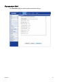
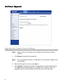
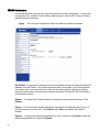
1
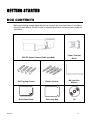
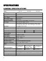
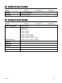
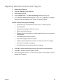
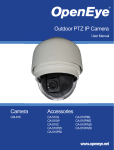
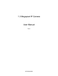
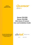
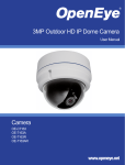
2MP Outdoor IR IP Bullet Camera
User Manual
Camera
CM-722I
CM-722AI
CM-722VF
www.openeye.net
2
2MP IR IP Bullet Camera (CM-722 Series)
User Manual
Manual Edition 31051AC – JULY 2013
©2013, OPENEYE
All Rights Reserved.
No part of this documentation may be reproduced in any means, electronic or mechanical, for any
purpose, except as expressed in the Software License Agreement. OpenEye shall not be liable for
technical or editorial errors or omissions contained herein. The information in this document is
subject to change without notice.
The information in this publication is provided “as is” without warranty of any kind. The entire risk
arising out of the use of this information remains with recipient. In no event shall OPENEYE be
liable for any direct, consequential, incidental, special, punitive, or other damages whatsoever
(including without limitation, damages for loss of business profits, business interruption or loss of
business information), even if OPENEYE has been advised of the possibility of such damages and
whether in an action or contract or tort, including negligence.
This documentation is copyrighted. All other rights are reserved to OPENEYE. OPENEYE, and
OpenEye, are registered trademarks of OPENEYE in the United States and elsewhere; Windows,
and Windows XP Embedded are registered trademarks of Microsoft Corporation. All other brand
and product names are trademarks or registered trademarks of the respective owners.
OPENEYE
Liberty Lake, WA ● U.S.A.
31051AC
3
Important Safeguards
1.
Read Instructions
Read all of the safety and operating instructions before using the product.
2.
Retain Instructions
Save these instructions for future reference.
3.
Attachments / Accessories
Do not use attachments or accessories unless recommended by the appliance
manufacturer as they may cause hazards, damage product and void warranty.
4.
Installation
Do not place or mount this product in or on an unstable or improperly supported
location. Improperly installed product may fall, causing serious injury to a child or
adult, and damage to the product. Use only with a mounting device
recommended by the manufacturer, or sold with the product. To insure proper
mounting, follow the manufacturer's instructions and use only mounting
accessories recommended by manufacturer.
5.
Power source
This product should be operated only from the type of power source indicated on
the marking label.
Precautions
Operating
•
Before using, make sure power supply and others are properly connected.
•
While operating, if any abnormal condition or malfunction is observed, stop
using the camera immediately and then contact your local dealer.
Handling
4
•
Do not disassemble or tamper with parts inside the camera.
•
Do not drop or subject the camera to shock and vibration as this can
damage camera.
•
Do not block the cooling holes on the bracket. This camera has a cooling
fan inside the housing. Blocking the cooling holes will cause heat to build up
and cause malfunction.
•
Care must be taken when you clean the clear dome cover. Scratches and
dust will ruin the image quality of your camera. Do not use strong or
abrasive detergents when cleaning the camera body. Use a dry cloth to
clean the camera when it is dirty. In case the dirt is hard to remove, use a
mild detergent and wipe the camera gently.
Installation and Storage
•
Install electricity wiring carefully. Please note that input electricity to the unit
is at tolerance of DC 12V/AC 24V ± 10%. The camera is capable of surge
protection; ensure AC power model unit is grounded appropriately against
damage by heavy current or electric shock.
•
Do not install the camera in areas of extreme temperatures in excess of the
allowable range. ( -40°F ~ 122°F / -40°C ~ 50°C)
•
Avoid installing in humid or dusty places. The relative humidity must be
below 90%.
•
Avoid installing in places where radiation is present.
•
Avoid installing in places where there are strong magnetic fields and electric
signals.
•
Avoid installing in places where the camera would be subject to strong
vibrations.
•
Never face the camera toward the sun. Do not aim at bright objects.
Whether the camera is in use or not, never aim it at the sun or other
extremely bright objects. Otherwise the camera may be smeared and
damaged.
Regulation
This device complies with Part 15 of the FCC Rules. Operation is subject to
the following two conditions: (1) this device may not cause harmful
interference, and (2) this device must accept any interference received,
including interference that may cause undesired operation.
This symbol on the product or on its packaging indicates that this product
shall not be treated as household waste in accordance with Directive
2002/96/EC. Instead it shall be handed over to the applicable collection point
for the recycling of electrical and electronic equipment. By proper waste
handling of this product you ensure that it has no negative consequences for
the environment and human health, which could otherwise be caused if this
product is thrown into the garbage bin. The recycling of materials will help to
conserve natural resources.
For more details information about recycling of this product, please contact
your local city office, your household waste disposal service or the shop
where you purchased the product.
Compliance is evidenced by written declaration from our suppliers, assuring that any
potential trace contamination levels of restricted substances are below the maximum level
set by EU Directive 2002/95/EC, or are exempted due to their application.
31051AC
5
Warning
DANGEROUS HIGH VOLTAGES ARE PRESENT INSIDE THE ENCLOSURE.
DO NOT OPEN THE CABINET.
REFER SERVICING TO QUALIFIED PERSONNEL ONLY.
Caution
CAUTION
RISK OF ELECTRIC SHOCK
DO NOT OPEN
CAUTION: TO REDUCE THE RISK OF ELECTRIC SHOCK,
DO NOT REMOVE COVER (OR BACK).
NO USER-SERVICEABLE PARTS INSIDE.
REFER SERVICING TO QUALIFIED SERVICE PERSONNEL.
6
TABLE OF CONTENTS
Introduction ................................................................................................................................... 10
Overview .................................................................................................................................... 10
Product Features ................................................................................................................... 10
Getting Started .............................................................................................................................. 11
Box Contents .............................................................................................................................. 11
Camera Overview ....................................................................................................................... 12
Dimensions ............................................................................................................................ 12
Connections ........................................................................................................................... 13
Micro SD Card Slot and Reset Button.................................................................................... 14
Installing the Desiccant .......................................................................................................... 16
Installation ..................................................................................................................................... 17
Power and Ethernet Connection ................................................................................................. 17
Power Connection.................................................................................................................. 17
Ethernet Cable Connection .................................................................................................... 17
Ceiling Installation ...................................................................................................................... 18
Lens Adjustment ......................................................................................................................... 19
Locate Camera............................................................................................................................... 20
OpenEye Network Camera manager.......................................................................................... 20
Installation .............................................................................................................................. 20
Starting Network Camera Manager........................................................................................ 20
Device Addressing ................................................................................................................. 21
Finding Network Devices .................................................................................................. 21
Setup & Configuration .................................................................................................................. 22
Connecting to the Camera .......................................................................................................... 22
Resetting the Camera ............................................................................................................ 22
Administrator/User Privileges ................................................................................................. 22
Connecting a Stream ............................................................................................................. 23
Connecting Over the Internet ................................................................................................. 24
Viewer Software ......................................................................................................................... 25
Viewer Tabs ........................................................................................................................... 25
Home ..................................................................................................................................... 26
CM-722I and CM-722VF Models....................................................................................... 26
CM-722AI .......................................................................................................................... 27
31051AC
7
System ................................................................................................................................... 28
System .............................................................................................................................. 28
Security ............................................................................................................................. 29
Admin Password .......................................................................................................... 29
Add User ...................................................................................................................... 30
Delete user ................................................................................................................... 30
Edit user ....................................................................................................................... 30
Network ............................................................................................................................. 31
Get IP address automatically (DHCP) .......................................................................... 31
Use fixed IP address .................................................................................................... 32
DDNS ................................................................................................................................ 33
Mail ................................................................................................................................... 34
FTP ................................................................................................................................... 35
Application ........................................................................................................................ 36
Motion Detection ............................................................................................................... 38
Storage Management........................................................................................................ 42
Recording.......................................................................................................................... 43
Snapshot ........................................................................................................................... 44
Information ........................................................................................................................ 45
System Log .................................................................................................................. 45
View User Information ....................................................................................................... 46
View User Privilege ...................................................................................................... 46
Parameter List ................................................................................................................... 47
Software Upgrade ............................................................................................................. 48
Upgrading the Camera Viewer Software ...................................................................... 48
Maintenance...................................................................................................................... 50
Video and Audio Streaming Settings ..................................................................................... 51
Video Format..................................................................................................................... 51
Text Overly Settings ..................................................................................................... 51
Video Rotate Type........................................................................................................ 52
Video Compression ........................................................................................................... 53
Video OCX Protocol .......................................................................................................... 54
Multicast Mode ............................................................................................................. 54
Frame Rate Control........................................................................................................... 55
Video Mask ....................................................................................................................... 56
Audio ................................................................................................................................. 57
Transmission Mode ...................................................................................................... 57
Server Gain Setting ...................................................................................................... 58
8
Bit Rate ........................................................................................................................ 58
Camera .................................................................................................................................. 59
Exposure ........................................................................................................................... 59
White Balance ................................................................................................................... 60
Backlight Setting ............................................................................................................... 60
Brightness ......................................................................................................................... 60
Sharpness ......................................................................................................................... 60
Contrast ............................................................................................................................ 61
Saturation.......................................................................................................................... 61
Digital Zoom ...................................................................................................................... 61
IR Function ........................................................................................................................ 61
TV System ........................................................................................................................ 61
Logout .................................................................................................................................... 61
Specifications ................................................................................................................................ 62
Camera Specifications ................................................................................................................ 62
IR Specifications ......................................................................................................................... 63
IP Specifications ......................................................................................................................... 63
Appendix A .................................................................................................................................... 64
Set Up Internet Security ............................................................................................................. 64
Setting Internet Security Level to Default ............................................................................... 64
Adjusting ActiveX Controls and Plug-ins ................................................................................ 65
31051AC
9
INTRODUCTION
OVERVIEW
The OpenEye CM-722 series is a collection of 2MP outdoor IP bullet cameras built to
provide superior video quality. All CM-722 cameras utilize MJPEG or H.264 compression
to provide video at resolutions up to 1080p (2MP) and are capable of dual and quad
streaming at 720p (1MP). Each camera in the CM-722 series is equipped with 23 IR LEDs
and a mechanical IR cut filter for true day/night operation, allowing the camera to record
high-resolution images at 0 Lux.
The CM-722I is equipped with all the standard features of the CM-722 line, while the CM722AI includes a motorized lens and the CM-722VF includes a varifocal lens.
The CM-722 series is designed to operate in extreme conditions in a tamper-resistant
housing. It is equipped with an integrated heater, allowing operation in temperatures as
low as -40°F (-40°C). CM-722 cameras can be powered via 24vAC, 12vDC, or a PoE
switch. 24vAC power is required to operate the on-board heater.
Product Features
10
•
ONVIF™ compliant
•
H.264 / MJPEG quad streaming
•
2MP resolution (1080p HD)
•
IP66 weatherproof rating
•
True Day/Night
•
On-board heater
•
23 IR LEDs
GETTING STARTED
BOX CONTENTS
Before proceeding, please check that the box contains the items listed here. If any item is
missing or has defects, DO NOT install or operate the product and contact your dealer for
assistance.
CM-722 Series Camera (Cable included)
31051AC
Power Terminal
Block
Self Tapping Screws
Plastic Anchors
M4 Inner Hex
Wrench
Quick Start Guide
Desiccant Bag
CD
11
CAMERA OVERVIEW
Before installing or connecting the camera, please refer to this section, including an
overview of the all-in-one cable for reference.
Dimensions
10.5” (266.7 mm)
2.75” (69.9 mm)
12
•
Length – 10.5 inches (84 mm)
•
Width – 2.75 inches (69.9 mm)
•
Height – 3.25 inches (82.55 mm)
Connections
No.
Item
Pin
Definition
1
Network (with PoE)
-
RJ-45 connector w/ LED
2
Power (3-pin Terminal
Block)
1
AC 24V-1
DC (-)
2
GND
Reserved
3
AC 24V-2
DC (+)
1
ALM_DI-
2
ALM_DI+
3
ALM_DO-
4
ALM_DO+
Pink
Line In/Mic In
Green
Line Out
-
Video out
3
Alarm I/O
Remarks
Power connection
Alarm connection
4
5
31051AC
Audio I/O
BNC
Two-way audio
transmission
13
Micro SD Card Slot and Reset Button
Use these photos to reach the Micro SD card slot, reboot button, and factory default button.
14
1.
Unscrew the camera housing to remove front cover.
2.
Micro SD card slot
31051AC
3.
Factory default button
4.
Reboot Button
15
Installing the Desiccant
To prevent condensation on the glass cover of the CM-722, OpenEye recommends
placing the desiccant in the camera before installation and replacing the desiccant each
time the front cover is opened.
16
1.
Unfasten the screw on the camera housing and remove the front cover
2.
Carefully tear open the aluminum desiccant envelope and remove the desiccant.
3.
Remove paper backing from the adhesive strip on the desiccant packet.
4.
Place the desiccant firmly in the position indicated in here.
5.
Reinstall the front cover and fasten the screw.
INSTALLATION
POWER AND ETHERNET CONNECTION
Read the installation instructions before installing and connecting the IP camera.
Power Connection
Make sure that the camera’s power cable is correctly and firmly connected..
Note
OpenEye recommends against using more than one power source at a
time. Do not use a PoE power source when providing the camera with
12vDC or 24vAC power.
Make sure the camera’s power cable is correctly and firmly connected. If using Power
over Ethernet (PoE), make sure Power Sourcing Equipment (PSE) is in use in the
network.
Ethernet Cable Connection
OpenEye recommends using Category 5 Ethernet cable to connect the camera to your
network. For the best transmission quality, the cable length should not exceed 328 feet
(100 meters). Connect a network cable to the camera using the RJ45 input and connect
the other end of the cable to your network switch or recorder.
Note
If you are connecting the camera directly to a recorder, a crossover cable is
necessary for most configurations.
Check the status of the network connection by looking at the link indicator and activity
indicator LEDs. If the LEDs are not lit check your network connection. The green link LED
indicates a network connection and the orange activity LED flashes to indicate network
activity.
31051AC
17
CEILING INSTALLATION
The IR Bullet IP Camera can be installed directly on a wall or ceiling provided it has
enough strength to support the camera.
1.
Remove the IR Bullet IP Camera from packaging
2.
Connect power, Ethernet, Alarm and audio wires from ceiling or wall to the
corresponding connectors of the cameras all-in-one cable.
3.
Fix the camera’s bracket on the ceiling or wall with the three supplied self-tapping
screws.
4.
Use the supplied inner hex wrench and a Phillips screwdriver to loosen the hex
bolt on the side of the bracket mount and the camera housing to adjust the
position of the camera.
Note
18
CM-722 cameras are equipped with a seal inside the housing to prevent
moisture from entering. If you have any concerns about moisture entering
the housing or wall through the cable egress , OpenEye recommends
sealing the opening at the wall and at the base of the camera with silicone
caulking.
LENS ADJUSTMENT
31051AC
1.
Unscrew the camera housing to remove front housing.
2.
Connect the power, audio, and alarm wires to their corresponding connectors.
(Refer to the pin definition table.)
3.
Access the camera browser in order to view images.
4.
Adjust the zoom/focus ring screw on the lens to set the desired zoom and focal
length.
5.
Replace front housing and tighten screw.
19
LOCATE CAMERA
OPENEYE NETWORK CAMERA MANAGER
Use the included Network Camera Manager software to easily find your network cameras
for initial setup. The OpenEye IP Finder software is included on the CD with all OpenEye
IP devices.
Installation
You can install Network Camera Manager on any personal computer (PC) or laptop using
the software CD included with your OpenEye IP camera or by downloading the program
from openeye.net.
Note
Network Camera Manager will only work on PCs or laptops that use a
Windows operating system. It is compatible with Windows XP, Vista, 7, and
8.
Starting Network Camera Manager
After installing the program on your PC or laptop, open the program to begin configuring
your cameras.
To access Network Camera Manager on an OpenEye recorder, you must operate the
recorder in Windows Mode.
20
1.
In the Live Screen, click Exit.
2.
Click Restart in Windows Mode.
3.
Click OK.
4.
Double-click Network Camera Manager.
Device Addressing
The functions on the Device Addressing tab allow you to find, configure, and view network
cameras.
Finding Network Devices
31051AC
5.
Click Find Devices on the Device Addressing tab.
6.
To narrow your search by Camera Model, Project, or Camera Name, select
your desired criteria from the appropriate lists.
21
SETUP & CONFIGURATION
CONNECTING TO THE CAMERA
1.
Locate the camera using the Network Camera Manager.
2.
Double-click the camera to open the Viewer software in your web browser.
3.
Log in to the camera with the appropriate User Name and Password.
Note
The default User name is Admin and the default Password is1234. The
username and password are case sensitive. OpenEye recommends you
change the Admin password for security reasons.
Resetting the Camera
If it is necessary to reset the camera to the factory default settings, hold down the Reset
button (see Connections) for 30 seconds. This will return all settings, including network
setup, to the factory default. The IP address of the camera will return to 192.168.0.250.
Administrator/User Privileges
The Administrator account has the authority to configure the IP camera and authorize
users’ access to the camera. The User accounts have access to the camera with limited
authority.
22
Connecting a Stream
OpenEye IP cameras are optimized for use with OpenEye recorders, but you can also
connect to your OpenEye IP cameras using third party software like VLC media player
(http://www.videolan.org).
To connect the camera you may need to provide the stream URL. All OpenEye IP
cameras are capable of delivering two RTSP streams, as well as streaming MJPEG over
HTTP. The stream URLs are listed below.
rtsp://<ip address>/mjpeg
rtsp://<ip address>/mpeg4
rtsp://<ipaddress>/h264
http://<ipaddress>:8008
The MJPEG over HTTP stream is identified by a port number. The default port is 8008;
this port can be configured in the cameras Network page:
31051AC
23
Connecting Over the Internet
There are some challenges with connecting to OpenEye IP cameras over WAN (internet)
connections because the camera streams video over RTSP. RTSP is an excellent
protocol for media and is now used on many IP cameras (including OpenEye) as the
default streaming option.
However, RTSP is not suitable for transmission between two locations that are behind
different routers. In this case, the client (for example, the OpenEye HVR or NVR server
software) connects to the camera, then requests a stream. The camera uses that
connection to return a stream, but since the connection originated on the client side and
has now switched to the camera (remote) side, the router does not have any way to
determine where the traffic should be routed, so no video appears at the recorder.
There are three solutions to this:
1.
Connect modems on both sides directly to the recorder and camera. If there is no
router, no network address translation is needed.
2.
Use routers with VPN support and set up a small VPN. Once this is done, the
traffic will be treated as though it were all on the local network.
3.
(Best solution) – Use routers with connection tracking. This is quite easy;
VOIP also uses RTSP and faces the same challenges. If a router is marketed as
having “VOIP Support”, it will have the necessary connection tracking capability
to allow any type of RTSP communication (not just VOIP).
With proper planning and the correct equipment, RTSP cameras CAN stream over the
WAN to a recording device for minimal additional cost and labor.
Please contact OpenEye support if you require any additional information on these topics.
24
VIEWER SOFTWARE
To access the setup menu, you need to install the viewer software on your PC or recorder.
The viewer software will install automatically the first time you connect to the camera. If
your internet browser doesn’t install the viewer software, check the security settings or
ActiveX controls and plug-in settings. For additional information on adjusting the settings
of your Internet Explorer browser contact your system administrator or refer to
openeye.net. If your internet browser asks for permission to install the ActiveX control, you
must allow the ActiveX control to continue the installation.
The first time you connect to a camera, the browser will ask for permission to install the
ActiveX Control necessary to display the camera video. Right-click the information bar and
click Install ActiveX Control to allow the installation. If you experience issues, see
Appendix A: Set Up Internet Security
Viewer Tabs
Home – Monitor live video.
System – Set the host name, system time, root password, and network related settings.
(Admin access only)
Streaming – Modify the video resolution and select the audio compression type.
Camera – Adjust the camera parameters including Exposure, White Balance, Brightness,
Sharpness, Contrast, and Digital Zoom.
Logout – Change user.
31051AC
25
Home
CM-722I and CM-722VF Models
Screen Size Adjustment – Click the screen size buttons to adjust image display size x1/2
and full screen.
Digital Zoom Control – In full screen mode, right-click to activate digital zoom and use
the scroll wheel to zoom in/out.
Talk – Talk allows the local site to talk to the remote site. This function is only available to
Users who have been granted this privilege by the Administrator.
Snapshot – Click the
button, and a JPEG snapshot will automatically be saved in
the appointed place. The default location is: C:\.
Note
26
If you are using Windows Vista or 7, you will need to change the Snapshot
location. Windows UAC does not allow internet programs to write directly to C:\
for security reasons.
CM-722AI
The CM-722AI is equipped with a motorized autofocus lens that makes installation quick
and easy.
There are six main buttons that are used when setting up the CM-722AI:
•
Zoom Tele
•
Zoom Wide
•
Focus Near
•
Focus Far
•
Push AF
•
Reset
Use these buttons to control the camera’s zoom and focus. Click Push AF to
automatically focus the camera. The camera will keep this focus setting until it receives
another command.
Once the CM-716A is installed in the preferred location, use the Zoom and Focus buttons
to set the camera’s field of view and then click the Push AF button to focus the camera.
To return the lens to the default setting, click Reset.
31051AC
27
System
Note
The System tab is only accessible by the Administrator.
System
Host Name – The Host Name is used to identify the camera on your system. If camerabased Motion Detection is enabled and is set to send alarm message by Mail/FTP, the
host name entered here will display in the alarm message.
Time Zone – Select your time zone.
Sync With Computer Time – Select to synchronize the camera date and time with the
connected PC or recorder.
Manual – Set video date and time manually.
Sync with NTP server – Network Time Protocol (NTP) is an alternate way to set your
camera’s clock by synchronizing with an NTP server. Specify the server you wish to
synchronize in the NTP Server box. Then select an Update Interval. For more
information about NTP, visit www.ntp.org.
28
Security
Admin Password
To change the administrator password, type a new password in the Admin Password box
and confirm below.
Note
31051AC
The maximum length of the password is 14 characters. The following
characters are valid: A-Z, a-z, 0-9, !#$%&’-.@^_~.
29
Add User
The user name and passwords are limited to 16 characters. The maximum number of user
accounts is 20.
4.
Type the new User name and Password.
5.
Select the appropriate check boxes to give the user Camera Control, Talk and
Listen permissions.
I/O access – Basic functions that enable users to view video when accessing to the
camera.
Camera control – Allows the User to change camera parameters on the Camera tab.
Talk/Listen – Talk and Listen functions allow the user at the local site (DVR) to
communicate with, the administrator at the remote site.
6.
Click Add.
Delete user
1.
Select the user name on the User Name list
2.
Click Delete to remove the user.
1.
Select the user name on the User Name list
2.
Click Edit to edit the user password and permissions.
3.
Type a new password or the existing password in the User password box
Edit user
30
Note
You must type a password in the User password box to make any changes
to an account.
Note
For security reasons every time the user properties are opened, the access
check boxes are automatically cleared. Make sure you select any user
access options each time you edit the user properties.
Network
You can choose to use a fixed IP address or a dynamic IP address (assigned by a DHCP
server or router) for the camera.
Get IP address automatically (DHCP)
The camera comes preconfigured with a fixed IP address.
Note
31051AC
Every network device has a unique Media Access Control (MAC) address
that can be used for identification. The MAC address is located on the
bottom of each camera, and on the box label (the OpenEye IP Finder also
displays the MAC address for identification). Record your camera’s MAC
address for identification in the future.
31
Use fixed IP address
To set up a new static IP address:
1.
Select the Use fixed IP address option.
2.
Type a new IP address in the IP address box.
3.
Type a new address in the Default Gateway box.
4.
Click Save to confirm the new setting.
When using static IP address to log in to the IP Camera, you can access it either through
OpenEye IP Finder software or type the IP address directly in the address bar of your
internet browser.
General
•
IP address – The IP Address is necessary for network identification.
•
Subnet mask – Used to determine if the destination is in the same subnet.
The default value is 255.255.255.0.
•
Default gateway – Used to forward frames to destinations on different
subnets or for internet access.
•
Primary DNS – The primary domain name server that translates hostnames
into IP addresses.
•
Secondary DNS – A secondary domain name server that backups the
primary DNS.
•
Web Server port – Defines the port that Internet Explorer uses to connect
over the web and view video. If this port is changed then the new port must
be defined when attempting to web connect (ex: if your camera’s IP address
is 192.168.0.100 and you change the web port to 8001, then you must type
http://192.168.0.100:8001 in your browser).
Advanced
•
RTSP port – The default RTSP port is 554; setting range: 1024 ~65535.
•
MJPEG over HTTP port – The default HTTP Port is 8008; setting range:
1024 ~65535.
Note
The MJPEG over HTTP port cannot be the same as the web server port.
Use PPPoE
For PPPoE users, enter the PPPoE username and password into the fields and click
Save to complete the setting.
IPv6 Address Configuration
With IPv6 support, users can use the corresponding IPv6 address for browsing.
Enable IPv6 by checking the box, then click Save to complete the setting.
32
DDNS
DDNS (Dynamic Domain Name Service) is a service that allows a connection to an IP
address using a hostname (URL) address instead of a numeric IP address. Most Internet
Service Providers use Dynamic IP Addressing that frequently changes the public IP
address of your internet connection. This means that when connecting to the camera over
the internet, you need to know if your IP address has changed. DDNS automatically
redirects traffic to your current IP address when using the hostname address.
31051AC
•
Enable DDNS – Select the check box to enable DDNS.
•
Provider – Select a DDNS host from the Provider list.
•
Host name – Type the registered domain name in the field.
•
Username/E-mail – Type the username or e-mail required by the DDNS provider for
authentication.
•
Password/Key – Type the password or key required by the DDNS provider for
authentication.
33
Mail
The camera can send an e-mail via Simple Mail Transfer Protocol (SMTP) when motion is
detected or when the sensor input is activated. SMTP is a protocol for sending e-mail
messages between servers. SMTP is a relatively simple, text-based protocol, where one
or more recipients of a message are specified and the message text is transferred. The
configuration page is shown as follows:
Two sets of SMTP accounts can be configured. Each set includes SMTP Server, Account
Name, Password and E-mail Address settings. For SMTP server, contact your network
service provider for more specific information.
34
FTP
The camera can send alarm message to a specific File Transfer Protocol (FTP) site when
motion is detected or when the sensor input is activated. You can assign alarm message
to up to two FTP sites.
31051AC
1.
Enter the FTP details, which include server, server port, user name, password
and remote folder, in the appropriate boxes.
2.
Click Save when finished.
35
Application
The CM-722 is equipped with one alarm input and one relay output to connect to an alarm
system to catch event images. Refer to Camera Overview > Connections to connect
alarm devices to the IP Camera if needed.
Alarm Switch – Enable or disable the alarm function.
Alarm Type – Select an alarm type, “Normal close” or “Normal open,” that corresponds
with the alarm application.
Alarm Output – Define alarm output signal “high” or “low” as the normal alarm output
status according to the current alarm application.
Triggered Action – Specify alarm actions that will take place when the alarm is triggered.
36
•
Enable Alarm Output – Select to enable relay output on alarm.
•
IR Cut Filter – Select the item and the camera’s IR cut filter (ICR) will be
removed or blocked when an alarm is triggered. The IR function cannot be
set to auto mode if the triggered action is enabled.
•
Send Alarm Message by FTP/E-Mail – Select to send an alarm message to
a configured FTP and/or E-Mail address when an alarm is triggered. When
sending to email, the alarm notification is text only. When sending to FTP,
the alarm notification will upload a text file to the FTP location.
•
Upload Image by FTP – Select to assign an FTP site. When the alarm is
triggered, event images will be uploaded to the configured FTP site at the
rate of one jpeg image per second.
•
Record Stream to SD Card – Select the item and the alarm-triggered
recording will be saved to your micro SD card. The pre-trigger buffer
recording option allows users to check what happened to trigger the alarm.
The pre-trigger buffer time range is from 1 to 3 seconds. Select Upload for
___ Sec to set the recording duration after the alarm is triggered. Select
Upload During Trigger Active to record until the alarm is off. Local
recording needs to be activated in order for this function to be implemented.
•
Upload Image by E-Mail – Select to assign an e-mail address. When the
alarm is triggered, event images will be sent to the configured e-mail
address.
•
Send HTTP notification – Select this item, select the destination HTTP
address, and specify the parameters for event notifications when an alarm is
triggered.
Note
Make sure SMTP or FTP configuration has been completed. See the Mail
and FTP section of this manual for further details.
File Name – Enter a file name in the box, ex. image.jpg. The uploaded image’s file name
format can be set in this section. Please select the one that meets your requirements.
•
Add date/time suffix
File name: imageYYMMDD_HHNNSS_XX.jpg
Y: Year, M: Month, D: Day
H: Hour, N: Minute, S: Second
X: Sequence Number
•
Add sequence number suffix (no maximum value)
File name: imageXXXXXXX.jpg
X: Sequence Number
•
Add sequence number suffix (limited value)
File Name: imageXX.jpg
X: Sequence Number
The file name suffix will end with the value entered in this box. For example,
if the setting is up to “10,” the file name will start from 00, end at 10, and then
start all over again.
Overwrite – The original image on the FTP site will be overwritten by the new uploaded
file with a static filename.
31051AC
37
Motion Detection
Motion Detection allows the camera to detect motion and trigger alarms when motion in
the detected area exceeds the determined sensitivity threshold value.
In the Motion Detection page, there is a motion detection window (red box) displayed on
the Live View Pane. The Motion Detection window defines the motion detection area. To
change the size of the Motion Detection window, drag the edge of the frame to resize.
You can add up to 10 motion detection windows.
38
•
Click Add under the Live View Pane to add a Motion Detection window.
•
To delete a Motion Detection window, use the mouse to select the frame and
click delete.
When motion detection is activated, the Motion pop-up window will open.
When motion is detected, the signals will be displayed on the Motion window as shown
below.
Motion Detection
Turn motion detection on or off. The default setting is Off.
Motion Detection Setting
31051AC
•
Sampling pixel interval [1-10] – Default value is 10, which means system
will take one sampling pixel for every 10 pixels.
•
Detection level [1-100] – Default detection level is 10. This item sets the
detection level for each sampling pixel; the smaller the value, the more
sensitive it is.
•
Sensitivity level [1-100] – The default sensitivity level is 80, which means if
20% or more sampling pixels are detected as changed, the system will
detect motion. The bigger the value, the more sensitive it is. As the
sensitivity value is increased, the red horizontal line in the motion indication
window will be lowered accordingly.
•
Time interval (sec) [0-7200] – The default interval is 10. The value is the
interval between each detected motion event.
39
Triggered Action
You can specify which actions the camera should take when motion is detected.
•
Enable Alarm Output – This will activate the camera’s alarm output.
•
Record Stream to SD Card – Select this item and the motion detection
recording will be stored in the Micro SD/SDHC card when motion is
detected. The pre-trigger buffer time range is 1-3 seconds. Select Upload
for ___ Sec to set the recording duration after motion is triggered. Select
Upload During the Trigger Active to record until the alarm is off.
•
Send Alarm Message by FTP/E-Mail – Select to send an alarm message to
a configured FTP server and/or e-mail address when motion is detected.
When sent to e-mail, the alarm notification is text only. When sending to
FTP, the alarm notification will upload a text file to the FTP location.
•
Upload Image by FTP – Select to assign an FTP site and configure various
parameters as shown in the figure below. When motion is detected, event
images will be uploaded to the appointed FTP site.
•
Upload Image by E-Mail – Select to assign an e-mail address and configure
various parameters as shown in the figure below. When motion is detected,
event images will be sent to the appointed e-mail address.
Note
•
40
Make sure SMTP or FTP configuration has been completed. See the Mail
and FTP sections for more information.
Send HTTP Notification – Check this item, select the destination HTTP
address, and specify the parameters for event notifications by motion
detection. When an alarm is triggered, the notification can be sent to the
specified HTTP server.
File Name – Enter a file name in the box, ex. image.jpg. The uploaded image’s file name
format can be set in this section. Please select the one that meets your requirements.
•
Add date/time suffix
File name: imageYYMMDD_HHNNSS_XX.jpg
Y: Year, M: Month, D: Day
H: Hour, N: Minute, S: Second
X: Sequence Number
•
Add sequence number suffix (no maximum value)
File name: imageXXXXXXX.jpg
X: Sequence Number
•
Add sequence number suffix (limited value)
File Name: imageXX.jpg
X: Sequence Number
The file name suffix will end at the value entered in this box. For example, if
the setting is up to “10,” the file name will start from 00, end at 10, and then
start all over again.
•
31051AC
Overwrite – The original image on the FTP site will be overwritten by the
new uploaded file with a static filename.
41
Storage Management
The CM-722 has an integrated microSD™ card that can be used to record video or
images. The card slot is compatible with a microSD™ card up to 32GB.
Device Information – Displays the storage total size and free space information of the
included microSD™ card.
Device Setting – Allows you to format the microSD card. (You will need to format the card
when using it for the first time.)
Device Cleanup Setting – Use this feature to enable overwrite settings on the SD card.
The camera can remove files from the card after they reach a certain age, or when the
card is a certain percent full.
Recording List – Displays a list of files saved to the card. You can delete files from the
card, or save them to your local PC.
Note
42
If you are using Windows Vista or 7, you will need to change the Snapshot
location. Windows UAC does not allow internet programs to write directly to
C:\ for security reasons.
Recording
The recording schedule allows you to set up scheduled recording to the microSD™ card.
Recording Schedule – The camera can be set up to record continuously until the card is
full (or overwrite old data, see the Storage Management section). The camera can also be
set up to record only during a scheduled time. Select the days that you would like to
record, then input the recording start time and the recording duration.
Activating microSD/SDHC Card Recording – Two types of schedule modes are offered:
Always and Time Frame. You can set up the time frame to fit the recording schedule or
choose Always to activate the microSD/SDHC card to record all the time.
Terminate microSD/SDHC Card Recording – Select Disable to terminate the recording
function.
31051AC
43
Snapshot
The camera supports a JPEG snapshot function. You can specify a storage location for
the snapshot images. The default location is: C:\.
44
Note
If you are using Windows Vista or 7, you will need to change the Snapshot
location. Windows UAC does not allow internet programs to write directly to
C:\ for security reasons.
Note
Make sure the selected file path contains valid characters such as letters
and numbers.
Information
The Information page contains the camera’s System Log, User Information and
Parameter List.
System Log
Click System Log to view the system log file. The content of the file provides useful
information about configuration and connections.
31051AC
45
View User Information
The Administrator can view each user’s login information and privileges on the View User
Information page.
All users for the camera are listed under User information. The example below shows
that the Admin password is 1234 and there is one user named User with the password
4321.
View User Privilege
Select a user account from the list and click get user privacy to view the permissions for
the user account.
46
Parameter List
Click Parameter List to view the system parameter settings.
31051AC
47
Software Upgrade
Upgrading the Camera Viewer Software
Note
1.
Click Browse and select the firmware file.
Note
48
Make sure the new firmware file is available before starting a software
upgrade.
Do not change the file name, or the system will not be able to update to the
new firmware.
2.
Select the file type from the list under Step 2.
3.
Click Upgrade. The system will check the upgrade file, and then upload the file.
The upgrade status bar will display on the page. When it reaches 100%, the
upgrade process is finished and the camera will return to the main page.
When the upgrade process is complete the viewer will return to the Home page. After
updating it is important to make sure the camera viewer software is updated:
31051AC
1.
Close your browser.
2.
Go to the Windows Control Panel and double-click Add or Remove Programs.
Locate the Camera Viewer software on the Currently installed programs list,
and click Remove to uninstall the previous software version.
3.
Open the internet browser again and login to the IP camera. The system will
automatically download the new version of the Camera Viewer software.
49
Maintenance
On the Maintenance page you can export the cameras current configuration, or import the
configuration for a camera. Use the factory default page to reset the IP Camera to factory
default settings if necessary.
Note
Do not import configuration files from different models of cameras.
Set Default –To reset the IP camera to the factory default settings, including the default IP
address, click Set Default. The system will restart after 30 seconds. If you cannot access
the camera menu, you can return the camera to the factory default settings by holding
down the reset button on the camera connection board for 30 seconds. See Connections
for the button location.
Reboot – To restart the IP camera without changing the current camera settings, Click
Reboot.
Export – You can save the system settings by exporting the configuration file (.bin) to a
specified location for future use. Click Export, then Save, and specify the desired
location.
Upload – To copy an existing configuration file to the IP camera, click Browse, select the
desired configuration file, then click Upload.
50
Video and Audio Streaming Settings
On the Streaming tab, you can configure specific video resolution, video compression
mode, video protocol and audio transmission mode.
Video Format
Select the desired video resolution for the camera on the Video Format page. The DVR
will record video based on the resolution selected here.
Text Overly Settings
Set up a text overlay for the transmitted video that can include the date, time, or custom
text.
31051AC
51
Video Rotate Type
You can change the orientation of the video output if necessary.
•
Normal transmits the image as the camera sees it.
•
Flip transmits the image upside down and mirrored.
•
Mirror transmits a mirror image.
•
180 degree transmits the image upside down.
GOP Settings
•
Sets the Group of Pictures (GOP) length for the H.264 streams. Use this to
increase bandwidth if necessary.
H.264 Profile
•
52
Sets the H.264 Profile, or type of H.264 compression, for each H.264
rd
stream. This may need to be changed only if you are using a 3 party NVR
that is not capable of decoding H.264 Main Profile.
Video Compression
You can select an MJPEG/H.264 compression mode on the video compression page
appropriate for your application. You can also select to display compression information
on the Home page.
MJPEG compression settings include:
•
high compression, low bit rate, low quality
•
middle compression, default
•
low compression, high bit rate, high quality
H.264 compression settings include:
•
1024kbps, highest compression, lowest quality
•
2048kbps
•
4096kbps, middle compression, default
•
6144kbps
•
8192kbps, low compression, highest quality
CBR Mode Setting
•
31051AC
The Constant Bit Rate (CBR) mode could be the preferred bit rate mode if
the bandwidth is limited. It is important to take account of image quality if
choosing to use CBR mode
53
Video OCX Protocol
On the Video OCX protocol page, you can select different protocols for streaming media
over the network. In the case of multicast networking, you can select the Multicast mode.
Video OCX protocol setting options include:
•
RTP over UDP
•
RTP over RTSP(TCP)
•
RTSP over HTTP
•
MJPEG over HTTP
Select a mode according to your data delivery requirements. If you are transmitting over
the internet using a router and port forwarding, you need to use RTP over RTSP (UDP).
You also need to forward the RTSP port to the camera (see the network setup page to
find the RTSP port).
Multicast Mode
54
1.
Enter all required data, including multicast IP address, H.264 video port, MJPEG
video port, audio port and TTL into each box.
2.
Click Save to confirm the setting.
Frame Rate Control
Setting the camera to transmit fewer frames can save bandwidth.
Each of the MJPEG and H.264 streams can have a separate frame rate setting from 1 to
30 frames per second
Note
31051AC
When set to 1920 x 1080, the max frame rate decreases to 15 frames per
second.
55
Video Mask
You can use the video mask page to define a privacy mask to keep users from viewing
parts of the image.
You can add two privacy masks and choose a color to obscure the live view from users.
Active Mask Function
•
Add a Mask – Check a video mask checkbox. Use the mouse to drag, drop,
and adjust the mask size and placement.
•
Cancel a Mask – Uncheck the checkbox for the desired mask.
Mask Setting
56
•
Mask Color – Masks can be red, black, white, yellow, green, blue, cyan, and
magenta.
•
Type – Masks can be solid or transparent.
Audio
On the Audio page, the Administrator can select an audio transmission mode and audio
bit rate.
Note
Audio monitoring and recording laws vary from location to location. It is
highly recommended that you consult your local, state and federal laws to
verify that you are in compliance before implementing audio recording.
Transmission Mode
31051AC
•
Full-duplex (Talk and Listen simultaneously) – In Full-duplex mode, the
local and remote sites can communicate with each other simultaneously, i.e.
both sites can speak and be heard at the same time.
•
Half-duplex (Talk or Listen, not at the same time) – In Half-duplex mode,
the local/remote site can only talk or listen to the other site at a time.
•
Simplex (Talk only) – In Talk only Simplex mode, the local/remote site can
only talk to the other site
•
Simplex (Listen only) – The local/remote site can only listen to the other
site.
•
Disable – Turn off the audio transmission function.
57
Server Gain Setting
Set the audio input/output gain levels for sound amplification. The audio gain values
range from 1 to 6. Sound can be turned off if audio gain is set to Mute.
Bit Rate
Selectable audio transmission bit rate include:
16 kbps (G.726)
24 kbps (G.726)
32 kbps (G.726)
40 kbps (G.726)
uLAW (G.711)
ALAW (G.711).
Both uLAW and ALAW signify 64 kbps but in different compression formats. Higher bit
rate will provide higher audio quality and require more bandwidth.
58
Camera
Exposure
The exposure is the amount of light received by the image sensor and is determined by
the width of lens diaphragm opening (iris adjustment), the amount of exposure by the
sensor (shutter speed) and other exposure parameters.
Full Auto Mode
•
In Full Auto mode, the camera’s Shutter Speed, IRIS and AGC (Auto Gain
Control) control circuits work together automatically to set a consistent video
output level. The maximum shutter speed is adjustable from 1/30 to 1 sec.
Auto Iris Mode
•
In Auto Iris mode, shutter speed and AGC circuit will function automatically
in order to achieve a consistent exposure.
Fixed Shutter Mode
•
31051AC
In Fixed Shutter mode, fixed shutter speed are user selected from the
available list. The shutter speed range is from 1/10000 to 1 sec. with 19
options. You can select suitable shutter speed according to the
environmental illumination.
59
White Balance
A camera needs to find reference color temperature, which is a way of measuring the
quality of a light source, for calculating all the other colors. The unit for measuring this
ratio is in Kelvin (K). Users can select one of the White Balance Control modes according
to the operating environment. The following table shows the color temperature of some
light sources for reference.
Light Source
Color Temperature in K
Cloudy Sky
6,000 to 8,000
Noon Sun and Clear Sky
6,500
Household Lighting
2,500 to 3,000
75-watt Bulb
2,820
Candle Flame
1,200 to 1,500
Auto Mode
•
In Auto mode, white balance works within its color temperature range and
calculates the best-fit white balance.
Auto Tracking White Balance (ATWB) Mode
•
In ATWB mode, the white balance will be automatically adjusted while the
color temperature is changing.
Manual Mode
•
In Manual mode, you can change the White Balance value manually,
adjusting the R gain and B gain.
Backlight Setting
Backlight compensation prevents the center object from being too dark in surroundings
where excessive light is behind the object.
Brightness
Adjust the image’s brightness on the camera. The Backlight value is adjustable from -12
(dim) ~ +13 (brightest).
Sharpness
Increasing the sharpness level can make the image looked sharper; it especially
enhances an object’s edge. The value of sharpness is adjustable from +1 ~ +15 (sharpest)
besides to default value.
60
Contrast
Correct the contrast of the entire image by adjusting the Contrast level, ranging from -6 ~
+19.
Saturation
Adjust the saturation of color components in an image through the Saturation function,
which is adjustable from -6 ~ +19.
Digital Zoom
Zoom in to the center of the image.
IR Function
Adjust the IR cut filter settings for Day/Night functionality. When set to Auto the camera
will analyze the video signal and choose when to switch from Day mode to night mode.
When set to On the camera will always be set to night mode, and when set to Off the
camera will always be set to day mode.
When set to Light Sensor the camera will only use the light sensor on the IR LED Array to
determine when to switch to night mode, when set to Light On the camera will always
have the IR LEDs turned on and when set to Light Off, the camera will always have the IR
LEDs off, even when in night mode.
When set to Smart mode, the camera automatically stays in night mode if the IR
illuminators remain on, even if the camera determines that it should switch to day mode.
TV System
Select the video format that matches the present video system.
Logout
Click the Logout tab to change users.
31051AC
61
SPECIFICATIONS
CAMERA SPECIFICATIONS
Model
CM-722I
CM-722AI
CM-722VF
Image Sensor
1/2.7” Progressive CMOS
Imaging DSP
Ambarella A5S
IP Rating
IP66
Type / Format
H.264 / MJPEG
Wide Dynamic Range
Digital WDR
Minimum Illumination
0.2 LUX (Color) / 0.02 LUX (B&W) / 0 LUX (IR LED)
Day / Night
Yes (True Day / Night) + IR LED
Resolution
15IPS @1920 x 1080 (2MP), 30 IPS @ 1280 x 1024 (1.3MP),
30 IPS @ 720p [1280 x 720 / 1MP), 30 IPS @ D1 [720 x 480],
30 IPS @ CIF (352 x 240]
Service Monitor Jack
Yes (BNC)
S/N Ratio
>50dB
Focal Length
4mm fixed
3 ~ 9 mm motorized
3 ~ 9 mm varifocal
Iris Control
F1.5
F1.2
F1.2
Synchronization
–
Video Output
1.0 Vp-p / 75Ω, BNC
White Balance
Manual / AWB / ATW
Auto White Balance Range
2700 K – 7800 K
Backlight Compensation
On/Off
Auto Gain Control
Auto/Manual adjustable through web
Operating Temperature
-40°F ~ 122°F (-40°C ~ 50°C)
Heater
Yes
Power Consumption
5W + 3W (IR LED)
+ 12W (Heater) =
20W
5W + 3W (IR LED)
+ 12W (Heater) +
4W (Lens) = 24W
5W + 3W (IR LED)
+ 12W (Heater) =
20W
Rated Amperage
0.84A (24vAC)
1A (24vAC)
0.84A (24vAC)
Input Voltage
12vDC / 24vAC / PoE
Weight
2.3 lbs (1 kg)
Dimensions
L: 10.5” (266.7 mm) W: 2.375” (60.325 mm) H: 3.5” (88.9 mm)
Housing / Dome Cover
White / Clear
62
IR SPECIFICATIONS
Model
CM-722I
IR LEDs
23 IR LEDs (850nm)
IR Range
Up to 50 ft (15 m)
CM-722AI
CM-722VF
CM-722AI
CM-722VF
IP SPECIFICATIONS
Model
CM-722I
Video Compression
H.264 / MJPEG
Dual Streaming
H.264 ONLY,
MJPEG ONLY,
H.264 + H.264,
H.264 + MJEG,
H.264 + H.264 + H.264,
H.264 + H.264 + MJPEG,
H.264 + H.264 + H.264 + H.264,
H.264 + H.264 + H.264 + MJPEG
Audio In
1
Audio Out
1
Alarm In
1
Alarm Out
1
User Account
20
31051AC
63
APPENDIX A
SET UP INTERNET SECURITY
If the installation of ActiveX Control is blocked, you will need to either set the Internet
Security Level to the default setting, or change the ActiveX controls and plug-ins setting.
Setting Internet Security Level to Default
64
1.
Open Internet Explorer.
2.
Click the Tools tab in the menu bar.
3.
Click Internet Options.
4.
In the Security tab, select the appropriate Internet Zone.
5.
Click Default Level.
6.
Click OK.
7.
Close the browser window. You will need to open a new window in order to
access the IP camera.
Adjusting ActiveX Controls and Plug-ins
1.
Open Internet Explorer.
2.
Click the Tools tab in the menu bar.
3.
Click Internet Options.
4.
Click Custom Level. The Security Settings window will pop up.
5.
Under ActiveX Controls and Plug Ins, set all items to Enable or Prompt.
Items may vary according to your version of Internet Explorer.
ActiveX controls and plug-ins settings:
31051AC
•
Allow previously unused ActiveX controls to run without prompt.
•
Allow Scriptlets.
•
Automatic prompting for ActiveX controls.
•
Binary and script behaviors.
•
Display video and animation on a web page that does not use external
media player.
•
Download signed ActiveX controls.
•
Download unsigned ActiveX controls.
•
Initialize and script ActiveX controls not marked as safe for scripting.
•
Run ActiveX controls and plug-ins.
•
Script ActiveX controls marked safe for scripting.
6.
Click OK to accept the settings and close the Security Settings window.
7.
Click OK to close the Internet Options screen.
8.
Close the browser window. You will need to open a new window in order to
access the IP camera.
65
www.openeye.net
1-888-542-1103
© 2013 OpenEye
All rights reserved. No part of this publication may be reproduced by any means without
written permission from OpenEye. The information in this publication is believed to be
accurate in all respects. However, OpenEye cannot assume responsibility for any
consequences resulting from the use thereof. The information contained herein is subject
to change without notice. Revisions or new editions to this publication may be issued to
incorporate such changes.
31051AC