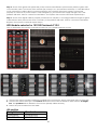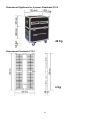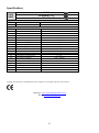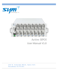
1
Pixelmesh P12,5 ORDERCODE 101390 Congratulations! You have bought a great, innovative product from DMT. The DMT Pixelmesh P12,5 brings excitement to any venue. You can rely on DMT, for more excellent lighting products. We design and manufacture professional light equipment for the entertainment industry. New products are being launched regularly. We work hard to keep you, our customer, satisfied. For more information: [email protected] You can get some of the best quality, best priced products on the market from DMT. So next time, turn to DMT for more great lighting equipment. Always get the best -- with DMT ! Thank you! Showtec DMT Pixelmesh P12,5™ Product Guide Warning ...............................................................................................................................................................................2 Safety Instructions .........................................................................................................................................................2 Operating Determinations ..........................................................................................................................................3 Rigging ............................................................................................................................................................................4 Return Procedure ..........................................................................................................................................................5 Claims ..............................................................................................................................................................................5 Description of the device .................................................................................................................................................6 Features ..........................................................................................................................................................................6 Overview ........................................................................................................................................................................7 Flightcase for 8 Pixelmesh P12,5 screens (101393) ..................................................................................................7 Overall Requirements .......................................................................................................................................................8 Set Up and Operation .......................................................................................................................................................8 Signal- and Powercable Connection .......................................................................................................................9 Setup Beam Angle ......................................................................................................................................................10 Truss Installation ...........................................................................................................................................................10 Setup Possibilities .........................................................................................................................................................11 1. Directly to a PC (via Cat5 max 75m) .............................................................................................................11 2. Via an Optic Tansmitter/Receiver (Distance > 50m) ..................................................................................11 Connecting cables, power supply ..........................................................................................................................12 Communication Wire Facture ..................................................................................................................................12 Making an additional Data cable ..........................................................................................................................12 Separately available (101401): Items included with the Software Bundle ......................................................13 Screen Control System Instruction ...........................................................................................................................14 PC Host Computer ......................................................................................................................................................14 Sender card .................................................................................................................................................................14 Sender card installation .............................................................................................................................................15 LED Studio Control System Installation ....................................................................................................................16 Installation of sending card ......................................................................................................................................18 Extend signal cable ....................................................................................................................................................20 Changing a standard signal to an optic signal ....................................................................................................20 Addressing cabinets ...................................................................................................................................................21 Patching the LED Pixelscreens ..................................................................................................................................23 Working with LED Studio.............................................................................................................................................29 Setting the Clock in LED Studio ................................................................................................................................35 Additional Accessories ..............................................................................................................................................38 Maintenance ....................................................................................................................................................................39 Troubleshooting ...............................................................................................................................................................40 Troubleshooting for LED module ..............................................................................................................................40 Troubleshooting for System .......................................................................................................................................40 Whole display does not work at all .....................................................................................................................40 Dimensions Flightcase for 6 pieces Pixelmesh P12,5 ................................................................................................42 Dimensions Pixelmesh P12,5..........................................................................................................................................42 Specifications ...................................................................................................................................................................43 1 Warning FOR YOUR OWN SAFETY, PLEASE READ THIS USER MANUAL CAREFULLY BEFORE YOUR INITIAL START-UP! Unpacking Instructions Immediately upon receiving this product, carefully unpack the carton and check the contents to ensure that all parts are present, and have been received in good condition. Notify the dealer immediately and retain packing material for inspection if any parts appear damaged from shipping or the carton itself shows signs of mishandling. Save the carton and all packing materials. In the event that a fixture must be returned to the factory, it is important that the fixture be returned in the original factory box and packing. Your shipment includes: • DMT Pixelmesh P12,5 •User manual LED Expected Lifespan LEDs gradually decline in brightness over time. HEAT is the dominant factor that leads to the acceleration of this decline. Packaged in clusters, LEDs exhibit higher operating temperatures than in ideal or singular optimum conditions. For this reason when all color LEDs are used at their fullest intensity, life of the LEDs is significantly reduced. It is estimated that a viable lifespan of 40,000 to 50,000 hours will be achieved under normal operational conditions. If improving on this lifespan expectancy is of a higher priority, place care in providing for lower operational temperatures. This may include climatic-environmental and the reduction of overall projection intensity. Safety Instructions Every person involved with the installation, operation and maintenance of this device has to: be qualified follow the instructions of this manual CAUTION! Be careful with your operations. With a dangerous voltage you can suffer a dangerous electric shock when touching the wires! Before your initial start-up, please make sure that there is no damage caused by transportation. Should there be any, consult your dealer and do not use the device. To maintain perfect condition and to ensure a safe operation, it is absolutely necessary for the user to follow the safety instructions and warning notes written in this manual. Please consider that damages caused by manual modifications to the device are not subject to warranty. This device contains no user-serviceable parts. Refer servicing to qualified technicians only. 2 IMPORTANT: The manufacturer will not accept liability for any resulting damages caused by the nonobservance of this manual or any unauthorized modification to the device. Never let the power-cord come into contact with other cables! Handle the power-cord and all connections with the mains with particular caution! Never remove warning or informative labels from the unit. Do not open the device and do not modify the device. Never use anything to cover the ground contact. Never leave any cables lying around. Do not connect this device to a dimmerpack. Do not shake the device. Avoid brute force when installing or operating the device. Do not switch the device on and off in short intervals. Never use the device during thunderstorms, unplug the device immediately. Avoid flames and do not put close to flammable liquids or gases. Only operate the device after having familiarized with its functions. Always allow free air space of at least 50 cm around the unit for ventilation. Always disconnect power from the mains, when device is not used or before cleaning! Only handle the power-cord by the plug. Never pull out the plug by tugging the power-cord. Make sure that the device is not exposed to extreme heat, moisture or dust. Make sure that the available voltage is not higher than stated on the rear panel. Make sure that the power-cord is never crimped or damaged. Check the device and the powercord from time to time. If the external cable is damaged, it has to be replaced by a qualified technician. If device is dropped or struck, disconnect mains power supply immediately. Have a qualified engineer inspect for safety before operating. If the device has been exposed to drastic temperature fluctuation (e.g. after transportation), do not switch it on immediately. The arising condensation water might damage your device. Leave the device switched off until it has reached room temperature. If your DMT device fails to work properly, discontinue use immediately. Pack the unit securely (preferably in the original packing material), and return it to your DMT dealer for service. The user is responsible for correct positioning and operating of the LED Pixelmesh. The manufacturer will not accept liability for damages caused by the misuse or incorrect installation of this device. This device falls under protection class I. Therefore it is essential to connect the yellow/green conductor to earth. Repairs, servicing and electric connection must be carried out by a qualified technician. For replacement use fuses of same type and rating only. WARRANTY: Till one year after date of purchase. Operating Determinations • This device is not designed for permanent operation. Consistent operation breaks will ensure that the device will serve you for a long time without defects. • The minimum distance between light-output and the illuminated surface must be more than 0.5 meter. • The maximum ambient temperature ta = 45°C must never be exceeded. • The relative humidity must not exceed 50 % with an ambient temperature of 45° C. • If this device is operated in any other way, than the one described in this manual, the product may suffer damages and the warranty becomes void. • Any other operation may lead to dangers like short-circuit, burns, electric shock, crash etc. You endanger your own safety and the safety of others! 3 Rigging Please follow the European and national guidelines concerning rigging, trussing and all other safety issues. Do not attempt the installation yourself ! Always let the installation be carried out by an authorized dealer ! Procedure: If the LED Pixelmesh is lowered from the ceiling or high joists, professional trussing systems have to be used. Use a clamp to mount the LED Pixelmesh, with the riggingmodule (101441/101442), to the trussing system. The LED Pixelmesh must never be fixed swinging freely in the room. The installation must always be secured with a safety attachment, e.g. an appropriate safety net or safety-cable. When rigging, derigging or servicing the device, always make sure, that the area below the installation place is blocked and staying in the area is forbidden. Improper installation can cause serious damage to people and property ! Connection with the mains Connect the device to the mains with the power-plug. Always pay attention, that the right color cable is connected to the right place. International EU Cable UK Cable US Cable Pin L BROWN RED YELLOW/COPPER FASE N BLUE BLACK SILVER NUL YELLOW/GREEN GREEN GREEN EARTH Make sure that the device is always connected properly to the earth! 4 Return Procedure Returned merchandise must be sent prepaid and in the original packing, call tags will not be issued. Package must be clearly labeled with a Return Authorization Number (RMA number). Products returned without an RMA number will be refused. Highlite will not accept the returned goods or any responsibility. Call Highlite 0031-455667723 or mail [email protected] and request an RMA prior to shipping the fixture. Be prepared to provide the model number, serial number and a brief description of the cause for the return. Be sure to properly pack fixture, any shipping damage resulting from inadequate packaging is the customer’s responsibility. Highlite reserves the right to use its own discretion to repair or replace product(s). As a suggestion, proper UPS packing or double-boxing is always a safe method to use. Note: If you are given an RMA number, please include the following information on a piece of paper inside the box: 1) Your name 2) Your address 3) Your phone number 4) A brief description of the symptoms Claims The client has the obligation to check the delivered goods immediately upon delivery for any shortcomings and/or visible defects, or perform this check after our announcement that the goods are at their disposal. Damage incurred in shipping is the responsibility of the shipper; therefore the damage must be reported to the carrier upon receipt of merchandise. It is the customer's responsibility to notify and submit claims with the shipper in the event that a fixture is damaged due to shipping. Transportation damage has to be reported to us within one day after receipt of the delivery. Any return shipment has to be made post-paid at all times. Return shipments must be accompanied with a letter defining the reason for return shipment. Non-prepaid return shipments will be refused, unless otherwise agreed in writing. Complaints against us must be made known in writing or by fax within 10 working days after receipt of the invoice. After this period complaints will not be handled anymore. Complaints will only then be considered if the client has so far complied with all parts of the agreement, regardless of the agreement of which the obligation is resulting. 5 Description of the device Features The Pixelmesh P12,5 is a fabulous LED panel from DMT. • Rental version • Dimensions: 400 x 800 x 59 mm (LxWxH) • Weight: 6 kg • Fullcolor indoor LED screen • Max Power Consumpion: 100W • Average Power Consumption: 34W • Data connection: RJ-45 • Power connection: Dedicated connector • Maximum hanging height: 8m (10 modules) • Easy to mount • Easy to service • Cooling: Convection • Well suited for permanent installations • 5 different angle positions • Ideal size ratio for creative set-ups • Nearly unlimited freedom to build your screen in any shape • The right indoor tool for the most demanding and creative visual designer • Combination of high transparency with a very flexible rigging system which allows for curved shapes with the panels. • Possible to adjust every panel both horizontally or vertically in five different angle positions (15°,7.5°,0°,7.5°,-15°). • Power supply: AC 100 - 230V - 50/60Hz • Refresh rate: Variable <1000Hz • Cabinet area: 0,32m² • Cabinet ratio: 1:2 • LED Lightsource:SMD3528 RGB • Pixel Pitch: 12 mm • Pixels per screen: 32 x 64 • Density (Pixel/m2): 6400 • Viewing Angle: 140˚ Horizontal, 140˚ Vertical • Luminance: 1.200 nits • Transparancy: 35% • Control mode: LED Studio- DVI through PC Sendercard • Operating temperature: 0 ~ 45°C • Operating humidity: 10% - 90% RH • IP Protection rate: IP-44 (INDOOR ONLY) • Mechanical connection: Fastlock system • Flightcase for 8 panels Pixelmesh P12,5 (101393) • Riggingmodule for Pixelmesh Riggingbar for 1 piece Pixelmesh P12,5 (101391) • Riggingmodule for Pixelmesh Riggingbar for 2 pieces Pixelmesh P12,5 (101392) Control • • • • • Software: LED Studio PC system with PCI slot and/or USB port, depending on the sendercard or video processor System: Windows Windows 7 or Windows 8 with video card (NOT included) Applications: Rental installations, small or large, interior / advertising /stage Works with other manufacturer’s software: Arkaos (see page 8) Recommended Arkaos Grand VJ, DMT Vision Express or Arkaos Mediamaster Pro 6 Overview Fig. 1 Flightcase for 8 Pixelmesh P12,5 screens (101393) Fig. 2 7 Overall Requirements • • • • • Operating system: Windows 7 or Windows 8 (compatible with LED Studio 11.78 and later) Processor: Intel Core 2 Duo E6600/AMD Athlon 64 6000+ or faster with at least one free PCI slot Harddisk: 40 GB Memory: 4 Gb or higher Graphic Card: Nvidia Geforce 88xx/ATi Radeon 4xxx or faster with dual display Mode and DVI output For up-to-date information about mediaservers or PC systems suitable for your specific demand, please contact your dealer VIDEO (Arkaos or DMT) In combination with Arkaos or DMT Software, you are able to play video over the Pixelmesh. You only have to connect all panels and run your software. Just click on the following pictures or ordercodes for more information 50227 DMT Vision Express: Easy to use and high performance at an affordable price 50223 Arkaos Grand VJ: Video Mixing Software 50228 Arkaos Media Master: PRO DMX video software for lighting designers Set Up and Operation Before plugging the unit in, always make sure that the power supply matches the product specification voltage. Do not attempt to operate a 120V specification product on 230V power, or vice versa. Always disconnect from electric mains power supply before cleaning or servicing. Damages caused by non-observance are not subject to warranty. The Pixelscreen Pixelmesh P12,5 can only be used indoors. The Pixelscreen Pixelmesh P12,5 can be viewed during night-time as well as day-time. Due to the clever mounting system it is easy to setup. The Pixelscreen Pixelmesh P12,5 excellent design allows you to vary the setup in many shapes and sizes. 8 Signal- and Powercable Connection 9 Setup Beam Angle Truss Installation Riggingbar for 1 piece Pixelmesh P12,5 (Ordercode 101391) Riggingbar for 2 pieces Pixelmesh P12,5 (Ordercode 101392) 10 Setup Possibilities 1. Directly to a PC (via Cat5 max 75m) 2. Via an Optic Tansmitter/Receiver (Distance > 50m) 11 Connecting cables, power supply CAUTION!!! Power supply cables have a high voltage of 240V cables. Extreme precaution should be taken when connecting them to the Pixelscreen. Do not supply power before the whole system is set up and connected properly. Communication Wire Facture C-Side 1 A-Side B-Side 8 B-Side Fig. 3 D-Side Making an additional Data cable A Standard NET CABLE can be used to replace the NET CABLE required to transmit the information for the LED Pixelscreen. Please follow the following instructions in order to create extra NET CABLE. Take a standard net cable (Cat5/ 5E /6) and connect it to the RJ-45 connector just like displayed on the picture. The wires should now be colored as following: 1- white & orange 2- orange 3- white & green 4- blue 5- white & blue 6- green 7- white & brown 8- brown RJ-45 Connector Insert each wire into an RJ-45 connector with the white & orange wire connected to PIN 1, the orange wire connected to the second PIN, etc. Both ends of the NET WIRE are connected in this way. 12 Separately available (101401): Items included with the Software Bundle User manual PC Sender Card DVI cable (DVI to DVI) CD with LED Studio 11.78 Fig. 2 USB cable 13 Screen Control System Instruction Sender card: • Make sure the PC is switched off. Take anti-static precautions, otherwise the entire PC can become damaged. • Install the LED Studio software on the PC. • Install the sender card on the PCI slot of the PC. • Connect the DVI Port of the transmission card and DVI Display Port by DVI Cable. • Connect the USB cable. • Start your PC. • Green LED blinks : DVI receives a video signal • Green LED OFF : DVI receives NO video signal Indicator light on the stage of twinkle status when the modules work normally. Fig. 3 PC Host Computer • PC should contain a Graphic Card with a double output: VGA + DVI output DVI + DVI output Sender card Install the sender card in an available PCI slot in your computer. The sender card is the interface between your PC, LED Studio and the Pixelmesh P12,5. You must use the DVI cable provided to connect from the computers DVI output to the DVI port on the sender card. USB Port Connects to PC and the LED Studio Software. DC External Power Input This input takes the 5V power supply provided. It is only used if the sender card will be operated eternally of the computer. 14 Sender card installation 1) Turn off your computer and disconnect from the powersource. Always take these precautions before opening the case and adding/removing components. Install the LED Studio Software on your PC. 2) Insert the sender card into an available PCI slot in your computer. 3) Connect the DVI output from your computer’s display card to the DVI input on the sender card, using the DVI signal cable provided. 4) Connect your computer’s USB port to the USB port of the sender card, using the included cable provided. 5) Connect the RJ45 OUT 1 to the LED screen. 6) When you want to display 256 row lines, connect the OUT 2 to a second controller. 7) Make sure that all connections are correctly connected, before applying power to the entire system. 8) In order to test the system successfully, it will be necessary to address the controllers correctly. 9) Once the controllers are assigned, turn on the computer and test the system. Fig. 13 Warning When your PC starts up and your screen stays black after connecting the sender card, turn off your computer immediately and disconnect the DVI cable from the sender card. Reboot your PC and when Windows has loaded, reconnect the DVI cable. 15 LED Studio Control System Installation • Put the LED Studio CD in the PC and then enter the installation setup. If not, please double click the CD, choose LED Studio Installation to start the installation. The Display shows LED Studio (see Figure below). Select the English language : Then click OK 16 Fill in your serial number 888888 • The following icon will appear on the desktop after finshing the entire installation: • Double click the Chart Icon to start the following screen: 17 Installation of sending card Graphical Videocard (NOT included !) Sendercard (101401 or 101404) Together with your PC interface + Software (101401) you received a Sender card (part of controller), a DVI connecting cable which connects the DVI output from your graphic card and DVI input in sender card. Also included is a USB cable. Always install the software and the USB driver before installing the card Please insert your sender card in an empty slot on the mainboard of your PC. The sender card from our controller can be recognized by computer only, after you will install LED STUDIO 10 software to your computer. After installation of the sender card, you can connected it with the supplied DVI cable and USB cable. There are 2 interfaces on sthe sender card for data Ethernet cable, you can use one of them to plug in data cable to send signal to LED display. Graphic card and sending card connected together with supplied DVI cable Connect the USB cable to the USB port of the PC and USB port of the sender card The USB cable is used to control the brightness levels and screen size. 18 DVI cable graphic (video) card sender card Make sure the graphic card and sender card are firmly connected. The green and red lamp of the sender card will light up when the two cards work well and receive the video signal on the DVI port. 19 Extend signal cable The longest distance of network cable connecting the sender- and receiver-card without relay, must be less than 75 meter. If it is more than 75 meter, you should use an optic cable or the DMT RP7010 repeater (ordercode 101410). DMT RP7010 repeater (ordercode 101410) Changing a standard signal to an optic signal A B B A Additional Accessories SPUNI001-Single Optic Transmitter+Receiver max 20 Km SPUNI002-Double Optic Transmitter+Receiver max 500 m SPUNI003-Single Optic cable p/m SPUNI004-Double Optic cable p/m See page 38 for more accessories 20 Addressing cabinets Cabinets are addressed from computer, by use of LED STUDIO 10 software. After opening the main widow of LED STUDIO 11, please go to Option and click on it with the left mouse button. A new window will appear, choose Software Setup and click the left mouse button. When the Software Setup window appears on the screen, just type linsn on your computer keyboard. Note: no dialog box will appear on the screen to type it in. After this another new window will open, requesting for a password. Now type the password: 168 21 On the new window go to the Display connection tab, and click on it with left mouse button. The display will show: 22 Patching the LED Pixelscreens If we need to change the amount of panels used in the setup, we have to instruct the software how many cabinets we want to control. We can do this by entering the number of cabinets in our display panel. First input horizontal card = 0; vertical card 0 To reset the settings on your display, enter the number of panels in your setup. 23 As an example we have chosen 4 x 3 cabinets. Please enter the desired number of cabinets you are using in your setup). After setting up the number of cabinets, the display will show: PC Net Cable In First Panel We have to inform receiving card installed in our “first cabinet”, to which Ethernet slot ‘U” or “D” signal cable is connected. ( Signal cable from our computer to LED display panel). The First cabinet is the cabinet to which the data cable from computer is connected. The next step is to inform the receiver card how many pixels are in one cabinet. For the Pixelmesh P12,5 screens, this is 64X72 pixels tell the software which is the first screen and then click on the grey block. Now jump with the arrow keys to the next panel and follow the order in which the screen is wired. 24 Please be sure to select the proper main cable (1 No. sender U cable). 25 Then press “send to receiver” The display will show: And the data will be uploaded to the receiver. Press OK, when this procedure is finished. 26 The display will show: Now “save to receiver” will be lit. Press save to receiver. And the data will be saved to the receiver. 27 After that, the display will show: Press OK. This procedure is finished and you’re ready to go. 28 Working with LED Studio 1) Open LED studio by clicking on the icon. The display shows: 2) Click here to open a new file. 3) Click on new page of program Button. 29 4) Choose a universal program (Loopplay) or normal program (play in order one by one). 5) Click New Window. 30 6) Each program window can play different words, pictures, tables, cartoons, and videos, etc. In total, there are twelve kinds of program windows available. 7) Blue screen = File Play Window 31 8) Click file. 9) Click Add File. 32 10) Choose a file. 11) Click the file you want and press open. 33 12) You now can set up your desired settings in the display area. You can control the width, height, etc. 13) After this you are able to choose more playable files until you are satisfied with the setup. 34 Setting the Clock in LED Studio 1) Open LED studio by clicking on the icon. The display shows: 2) Click here to open a new file. 3) Click on new page of program Button. 35 4) Choose a universal program (Loopplay) or normal program (play in order one by one). 5) Click New Window. 36 6) Click the Date/Time Window 7) If you want to set a clock in the display, open a clock file in the Universal Display and set the specifications of the clock. The clock will be displayed all the time. 37 Additional Accessories 101391-Riggingbar for 1 piece Pixelmesh P12,5 101392-Riggingbar for 2 pieces Pixelmesh P12,5 101394 Powercable 101395 P12,5 Data Inputcable 101396 Data Linkcable 101397 Data-Coupler 101393 MCA-PIXM2 Flightcase for 8x Pixelmesh 101401 DMT S8020 Sender Card 101414 LS-120 Videoprocessor 101412 S6010 HUB for Pixelscreen/Mesh 101416 LS-170 Videoprocessor (incl sender card) 101418 SB-801 Senderbox 101417 LS-180 Videoprocessor (incl sender card) 101419 SD-8 Signaldistributor 38 Maintenance The operator has to make sure that safety-relating and machine-technical installations are to be inspected by an expert after every four years in the course of an acceptance test. The operator has to make sure that safety-relating and machine-technical installations are to be inspected by a skilled person once a year. The following points have to be considered during the inspection: 1. All screws used for installing the device or parts of the device have to be tightly connected and must not be corroded. 2. There may not be any deformations on housings, fixations and installation spots. 3. Mechanically moving parts like axles, eyes and others may not show any traces of wearing. 4. The electric power supply cables must not show any damages or material fatigue. The DMT Pixelscreen Pixelmesh P12,5 requires almost no maintenance. However, you should keep the unit clean for a better product life and performance. Buildup of dust, dirt, smoke particles, fog fluid residues, etc. degrades the panel’s light output. Cleaning schedules for lighting fixtures vary greatly depending on the operating environment. It is therefore impossible to specify precise cleaning intervals for the Pixelscreen. In extreme cases panels may require cleaning after surprisingly few hours of operation. Environmental factors that may result in a need for frequent cleaning include: •Use of smoke or fog machines. •High airflow rates (near air conditioning vents, for example). •Presence of cigarette smoke. •Airborne dust (from stage effects, building structures and fittings or the natural environment at outdoor events, for example). If one or more of these factors is present, inspect panels within their first 25 hours of operation to see whether cleaning is necessary. Check again at frequent intervals. This procedure will allow you to assess cleaning requirements in your particular situation. If in doubt, consult your DMT dealer about a suitable maintenance schedule. Do not use alcohol , abrasive, caustic or solvent-based products for cleaning, as they can damage plastic or painted surfaces. To clean the panel: 1) Disconnect the panel from power and allow it to cool for at least 10 minutes. 2) Vacuum or gently blow away dust and loose particles from the fan blades and grilles in the base of the panel with compressed air. 3) Wipe the outside of the Pixelscreen with a soft, lint-free cloth. Make sure connections are thoroughly dry before linking equipment or supplying electric power. 39 Troubleshooting Troubleshooting for LED module I. II. III. IV. Failure: All LEDs blink. Cause: Connection failure. Solution: Fix the loose places or re-plug. Check or replace the DVI cable. Failure: LED appears dark. Cause : Switching power is inconsistent with LED’s rated voltage. Solution: Make sure switching power is conforming to rated voltage of LED. Failure: LED lamps on a certain circuit are not lit. Cause: 1. Connection direction may be wrong; 2. Cable of output power may be wrongfully connected; 3. Power cables may be reversely plugged or connected. Solution: 1. Remove it and connect it properly; 2. Make sure the red cable is connected to the anode, and black cable to cathode; 3. Find out the reversely connected cables, then connect them correctly. Failure: All LED lamps are not lit. Cause: 1. No power output from switching power; 2. Output cables may be wrongly connected. Solution: 1. Connect the power to the input port of switching power; Troubleshooting for System Whole display does not work at all Step 1: Check if the video (graphic) card is set properly, please refer to the user manual of the graphic card. Step 2: Check the basic connections of the system, example powercables, DVI cable, signal cable sockets, the connection between the master card and PCI slot of computer, USB cable, the connection of serial port lines, etc. Step 3: Check the computer and LED power system for compliance. When the power supply for the LED screen is insufficient and display color is close to white (indicating too much power consumption), images may flash. Before plugging the unit in, always make sure that the power supply matches the product specification voltage. Do not attempt to operate a 120V specification product on 230V power, or vice versa. Step 4: Check if the green LED of sender card flashes regularly. If the LED flashes go to Step 6; if not, please first try to reboot the system once. Before starting up the PC, please check if the green LED of sender card flashes regularly, if so go to Step 2. If not, check if the DVI cable is properly connected. If the green LED is not ON there is no video signal. If the problem is not solved, there is something wrong with the sender card, video card or DVI cable. Fix the probable cause and then repeat Step 3. check the video signal. Check the USB driver on your Windows PC. Use another USB port on your PC to connect your sendercard. If you have choosen “Send to Receiver”and nothing happens, change the output port on the sendercard. Change the cable from A to B or B to A AB After pressing send to receiver and the patch of the panels is still wrong, check the data cables. One of the cables may be damaged. If nothing happens on the Pixelscreen, check power cables. Step 5: Repeat the software setup for the graphic card or reinstall it, until the green LED of the sender card flashes, otherwise, repeat Step 3. 40 Step 6: Check if the green LED (data LED) of the receiver card flashes synchronously with the green LED of the sender card. If not check if the red LED (for power) is on, and continue with Step 7, if the RED LED is not lit, check if the yellow LED (for power protection) is lit, check if the power supply is connected properly or if there is no power output. If the LED lights up, just check if the supply voltage is 5V. If the problem still exists, there is a receiver card failure. Just replace the receiver card and repeat Step 6. Step 7: Check if the signal cable is properly connected or maybe it’s too long (maximum length of signal cable without relay must be less than 75 meters). If the problem still exists, there is a receiver card failure. Replace the receiver card and repeat Step 6. LED Module selector for 101390 Pixelmesh P12.5 How to determine the correct spare LED module for your 101390 Pixelmesh P12.5? Straight Line Quadrant Straight Line Quadrant 1. Choose the correct module number by looking at the connector, arrows and guide pins on the back. 2. Choose the correct LED type. The vertical LED has the four colors stacked on each other in a straight line. The quadrant LED is divided in four sectors (clearly visible sections). 3. Select the part number from the table. LED partition Straight line SPINFI0043 SPINFI00431 Quadrant SPINFI00432 SPINFI00433 41 Dimensions Flightcase for 6 pieces Pixelmesh P12,5 45 Kg Dimensions Pixelmesh P12,5 6 Kg 42 Specifications DATA SHEET 101390 Pixelmesh P12,5 Module 400 x 800 x 59 mm (1) Pixel Parameter NO. Item 1 Pixel Pitch (2) Module Parameter NO. Item 1 Module Size 2 Module Resolution 3 Density 4 Angle of View 5 Luminance/Brightness 6 Optimum Viewing Distance 7 Working Voltage 8 Module Weight 9 Refresh Rate 10 Control System 11 Control Distance 12 Operation Temperature 13 Operation Humidity 14 Protection Rating 15 Certification 16 LED Lightsource 17 LED Arrangement 18 LED Module Replacement 19 Cabinet Area Parameter 12 mm Parameter 400 x 800 x 59 mm (32x64 Pixels) 6400 Pixels/m2 140˚ Horizontal, 140˚ Vertical 1200 Nits 10 - 100m AC 100 - 230V - 50 Hz 6 kg Variable <1000Hz LED Studio - DVI through PC Sendercard <75m 0˚ - 45˚ 10% - 90% RH IP-44 INDOOR ONLY CE SMD3528 RGB 3 in 1 SMD 32 x 16 Pixels 0,32 m2 Design and product specifications are subject to change without prior notice. Website: www.DutchMediaTools.info Email: [email protected] 43 © 2013 DMT.