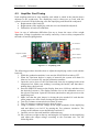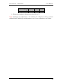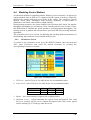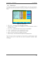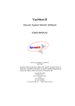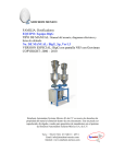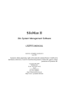
1
Gravimetric Doser
BIGG
5 Gravimans – User Manual
P.O.B. 1122, Afula Illit 18550, Israel
Tel: +972-4-6405857
Fax: +972-4-6405911
[email protected]
www.sysmetric-ltd.com
Manual Number: BIGG5G102
December, 2008
Line Control – 5 Graviman
User Manual
Table of Contents
1.
INTRODUCTION....................................................................................... 4
1.1.
1.2.
1.3.
1.4.
GRAVIMAN UNIT............................................................................................ 4
CONTINUOUS GRAVIMAN WEIGH-UNIT.......................................................... 4
PRINCIPLES OF OPERATION ............................................................................ 4
CREATING A CONTINUOUS DOSING SYSTEM .................................................. 5
2.
SYSTEM OVERVIEW .............................................................................. 6
2.1. CONTROL PANEL............................................................................................ 6
2.2. CONTROL DISPLAY ........................................................................................ 7
2.2.1. Entering Numeric Values ....................................................................... 7
2.2.2. Line Screen ............................................................................................. 8
2.2.3. Dosing Screen ........................................................................................ 9
2.2.4. Operate Screen ..................................................................................... 10
2.2.5. Service Screen ...................................................................................... 11
2.3. GRAVIMAN CONTROL BOX .......................................................................... 12
2.4. GRAVIMAN COMPONENTS ............................................................................ 13
3.
INSTALLATION AND OPERATION ................................................... 14
3.1. OVERVIEW ................................................................................................... 14
3.1.1. Top Flange (holding tank flange)......................................................... 14
3.1.2. Bottom Flange ...................................................................................... 15
3.2. SAFETY PRECAUTIONS ................................................................................. 15
3.3. GRAVIMAN INSTALLATION PROCEDURE ....................................................... 16
3.4. PRINCIPALS OF OPERATION .......................................................................... 17
3.5. UNLOADING AND CLEANING THE SYSTEM .................................................... 17
3.5.1. Cleaning the main channel ................................................................... 18
3.5.2. Cleaning the additive channel .............................................................. 18
4.
MAINTENANCE AND SERVICING..................................................... 19
4.1. TUNING THE HOLDING TANK SENSORS ......................................................... 19
4.1.1. Tuning procedure ................................................................................. 19
4.2. LOAD-CELL CALIBRATION ........................................................................... 20
4.3. AMPLIFIER CARD TUNING ............................................................................ 22
4.4. MODELING CONTROL METHOD.................................................................... 24
4.4.1. Parameters Screen ............................................................................... 24
4.4.2. Filling Thresholds ................................................................................ 25
4.4.3. Calculation Thresholds ........................................................................ 25
4.4.4. Model Screen ........................................................................................ 26
4.4.5. Model results ........................................................................................ 27
4.5. SPEED CALIBRATION.................................................................................... 28
4.5.1. Speed Data Screen ............................................................................... 28
4.5.2. Speed Calibration Screen ..................................................................... 29
4.5.3. Auto Calibration................................................................................... 29
5.
ALARMS ................................................................................................... 30
5.1. ALARMS SCREEN ......................................................................................... 30
5.2. ALARMS LIST ............................................................................................... 31
5.2.1. EX On & Graviman #X Off .................................................................. 31
www.sysmetric-ltd.com
-2-
Line Control – 5 Graviman
5.2.2.
5.2.3.
5.2.4.
5.2.5.
5.2.6.
5.2.7.
5.2.8.
5.2.9.
5.2.10.
5.2.11.
5.2.12.
5.2.13.
5.2.14.
5.2.15.
5.2.16.
5.2.17.
5.2.18.
User Manual
Low Material in Hopper #X ................................................................. 31
Low Material in Graviman #X ............................................................. 31
No Material in Graviman #X ............................................................... 32
Weighing Error in Graviman #X.......................................................... 32
Graviman #X – Screw Capacity too High ............................................ 32
Graviman #X – Screw Capacity too Low ............................................. 33
Additive #X Speed too Fast .................................................................. 33
Additive #X Speed too Slow .................................................................. 33
Additive #X Screw Motor Fault ........................................................ 34
PLC Low battery ............................................................................... 34
Ex Speed too Fast.............................................................................. 34
Unstable Speed.................................................................................. 34
S.D. too Big ....................................................................................... 35
No Pulses .......................................................................................... 35
Formula Over 100% ......................................................................... 35
Pump Over Load ............................................................................... 35
Conveying Failure Channel #X ........................................................ 35
www.sysmetric-ltd.com
-3-
Line Control – 5 Graviman
User Manual
1. Introduction
1.1. Graviman Unit
The Graviman continuous dosing unit is used for keeping track of the raw material
flow by the use of a loss-in-weight method. In this method, the rate of weight
reduction in the weighing bucket of the Graviman is consistently monitored.
The Graviman system features:
• Omron’s industrial Programmable Logic Controller.
• Omron’s color touch screen user interface console.
• Advanced modeling method (as opposed to regular methods such as PID etc.)
to control the speed of the extruder and the screw feeders. The modeling
algorithm has many advantages: high accuracy, immunity to many kinds of
disturbances, non-linear control and very high stability.
• Semi-automatic calibration.
• A combination of hardware and software signal conditioning and filtering
ensures shock and vibration resistant operation.
• No need for tuning or setup when replacing raw materials.
1.2. Continuous Graviman Weigh-unit
The Graviman weigh-unit can be operated in one of two ways:
1. As a single unit fixed straight on the feed throat of the production machine,
working as a continuous weight controller with one type of raw material.
2. As a combined dosing and weighing controlling unit with a number of
Graviman weighing modules. A central unit doses directly into the main outlet
pipe while secondary additive units use screw feeders to dose to the outlet
pipe. The central unit calculates the desired throughput while the secondary
units adjust their screw feeder outputs accordingly.
1.3. Principles of Operation
1. At startup, the system controller (PLC) checks the amount of material in the
weighing-bucket and fills it up as necessary by opening the pneumatic shutter.
2. The weighing-unit provides the PLC with continuous weight readout.
3. During production, when the material weight in the weighing bucket is reduced to
a predetermined minimum level, the pneumatic shutter is opened and the bucket is
refilled.
4. The PLC calculates throughput by using weight data and the RPM of the screw
feeder.
www.sysmetric-ltd.com
-4-
Line Control – 5 Graviman
User Manual
1.4. Creating a Continuous Dosing System
Linking several Graviman units and screw feeders is enough to create a continuous
dosing system. As a dosing system the controller calculates the throughput for each
screw feeder using data from the continuous weigh-unit. Each screw feeder is fixed to
a Graviman weigh-unit making closed loop control a possibility. The central system
controller uses loss-in-weight and screw feeder RPM in order to calculate the
percentage of screw rotation for each channel.
Each screw feeder in the dosing system has to be able to cope with its intended
throughput. The throughput for each channel is a function of batch composition
(material density) and system throughput.
Note: The explanation in this manual and the screen illustrations accompanying it,
refer to a continuous weighing system consisting of five combined Graviman units.
Screen attributes may vary from system to system.
www.sysmetric-ltd.com
-5-
Line Control – 5 Graviman
User Manual
2. System Overview
2.1. Control Panel
Omron NS-5
Display
ALARM
CANCEL
Figure 2.1-1 – Control panel
The control panel of the system consists of the following:
• ALARM CANCEL push-button – used for stopping the system alarm (R11
potential free contact) and to display and toggle unresolved alarms on the
control display.
• Touch screen display for programming and monitoring.
www.sysmetric-ltd.com
-6-
Line Control – 5 Graviman
User Manual
2.2. Control Display
Figure 2.2-1 – Control display
The control display is a color touch-screen panel. Each operation on the display is
carried out by pressing gently on the display. Activating a button is carried out by
pressing gently on the display where the button appears. Changing numeric values is
carried out by pressing gently on the display where the value is written.
2.2.1. Entering Numeric Values
Several screens (e.g. LINE screen) have one or more editable numeric items (e.g. the
percentage of each layer). To modify the value of an item, follow these steps:
1. Select the item that you want to edit by pressing gently on the display where
the item is written. A pop-up screen with a numeric keypad will appear on the
display.
2. Enter the new value using the numeric keypad. If the item has a decimal point,
use the ‘.’ key to move to the fractional part. For example, to enter 12.3, push
‘1’, ‘2’, ‘.’ followed by ‘3’.
3. Press the Enter key to confirm the change. The keypad screen will close and
the item will get the new value.
Cancel editing by pressing the X button in the keypad screen.
Figure 2.2-2 – Numeric keypad
www.sysmetric-ltd.com
-7-
Line Control – 5 Graviman
User Manual
2.2.2. Line Screen
The line screen is the main screen of the system. This screen shows the production
parameters. Press the LINE button to switch the display to the line screen.
Figure 2.2-3 – Line screen
The line screen shows the following data:
• Extruder Capacity – the capacity of the extruder in Kilograms per Hour.
• Dosing Capacity – the set and actual capacity of each channel of the dosing
system in Kilograms per Hour.
• Total – the total amount of material dispensed from the dosing system in
Kilograms.
www.sysmetric-ltd.com
-8-
Line Control – 5 Graviman
User Manual
2.2.3. Dosing Screen
The dosing screen is used for setting the dosing formula of the system. The dosing
formula is the percentage of each channel in the material blend that is fed to the
production machine. Press the DOSING button to switch the display to the dosing
screen.
Figure 2.2-4 – Dosing screen
The dosing screen shows the following data:
• SET – the desired percentage of each channel in the dosing formula.
• RPM – the current RPM of the extruder and the screw feeders of each channel.
• Total – the total amount of material dispensed at each channel.
Enter the required percentage of material from each channel (Ch#2 – Ch#5) and the
percentage of the main channel will adjust itself automatically to make up 100%.
www.sysmetric-ltd.com
-9-
Line Control – 5 Graviman
User Manual
2.2.4. Operate Screen
The operate screen is used for turning on and off the material conveyors. Press the
OPERATE button to switch the display to the operate screen.
Figure 2.2-5 – Dosing screen
Turn on and off the material conveyor for each Graviman (each channel) by pressing
the corresponding switch in the operate screen.
www.sysmetric-ltd.com
- 10 -
Line Control – 5 Graviman
User Manual
2.2.5. Service Screen
The service screen is used for setting different parameters of the system. Press the
SERVICE button to switch the display to the service screen.
Figure 2.2-6 – Dosing screen
In the main service screen set the correct time and date and adjust the brightness and
contrast of the operation display.
Press Calibration, Parameters, Model or Speed buttons to select one of the service
screens. See Maintenance and Servicing chapter for complete details on the different
service screens.
www.sysmetric-ltd.com
- 11 -
Line Control – 5 Graviman
User Manual
2.3. Graviman Control Box
Figure 2.3-1 – Graviman control box
Each Graviman has a control box with the following switches:
1. GRAVIMAN switch with 3 modes:
OPEN – the filling valve is always open (for system drainage)
CLOSE – the filling valve is always closed (for calibration)
AUTO – the filling valve opens and closes automatically to keep the
Graviman supplied with material (normal operation)
2. TEACH – initiating a teach cycle for learning the flow parameters of new
material.
•
•
•
www.sysmetric-ltd.com
- 12 -
Line Control – 5 Graviman
User Manual
2.4. Graviman Components
The continuous weighing-unit provides precise loss-in-weight information from the
weighing bucket to the system’s controller. The unit has been designed to protect the
bucket from all kinds of disturbances. The weigh-unit is made up of three main
components:
1. Outer housing which protects the weighing process from being disturbed in
any way. Two service hatches in the housing facilitate periodic checking and
cleaning of the bucket.
2. Pneumatic shutter to control the weighing bucket filling.
3. Weighing bucket on load-cell which continuously tracks the material flowing
through the system.
The following drawing shows a two channel combined Graviman unit with a
connective screw-feeder:
Figure 2.4-1 – Combined Graviman components (two channels)
1 – Main channel
6 – Additive channel
11 – Screw feeder
2 – Material level sensor
7 – Material level sensor
12 – Center pipe
3 – Pneumatic shutter
8 – Load Cell
4 – Load Cell
9 – Pneumatic shutter
5 – Weighing bucket
10 – Weighing bucket
www.sysmetric-ltd.com
- 13 -
Line Control – 5 Graviman
User Manual
3. Installation and Operation
3.1. Overview
The following is an overview of the steps required to install the Graviman unit and
check that it is working properly. The description assumes some prior technical
knowledge. For more information contact Sysmetric.
When installing this system, a few basic rules must be observed:
• Leave all service hatches clear of obstruction.
• The unit has to be positioned firmly on the feed throat of the production
machine.
• The unit has to be guarded against sources of mechanical damage (forklifts
etc.).
• All conveyors of system materials have to be firmly installed.
The system is composed of several components; the installation procedure consists of
laying them out, checking them, connecting them to the power and air supplies and
then joining them to each other and to the production machine.
The installation procedure includes:
• Unpacking the Graviman components.
• Checking the weighing unit of each channel for damage on delivery.
• Mounting and calibrating the load-cells.
• Mounting the holding tanks.
• Mounting the optional material loaders.
• Mounting the Graviman system onto the throat of the production machine.
3.1.1. Top Flange (holding tank flange)
Vacuum loaders and other material feeding equipment can be attached to this flange
using suitable adapters if needed.
www.sysmetric-ltd.com
- 14 -
Line Control – 5 Graviman
User Manual
3.1.2. Bottom Flange
The flange should be bolted to the throat of the production machine, usually with a
suitable adapter. An optional magnet chamber with a slide-gate, a drainage outlet and
a custom made bottom flange for the machine, can be supplied.
3.2. Safety Precautions
1. Checking and replacement of electrical parts must be performed by qualified
personnel only.
2. Disconnect the electrical power supply before servicing.
3. Disconnect the air supply before servicing pneumatics.
4. The electrical cabinet contains an electrical potential of 220VAC. The key to these
doors should be in the possession of service personnel only.
ATTENTION!
THE PNEUMATIC SHUTTERS OPERATE AUTOMATICALLY AND MAY
CHANGE POSITION WITHOUT WARNING
www.sysmetric-ltd.com
- 15 -
Line Control – 5 Graviman
User Manual
3.3. Graviman Installation procedure
1. Unpack the Graviman components and lay them out in the order that they will be
when assembled. Check for missing components.
2. Visually check all components for delivery damage, pay special attention to the
load-cells.
3. For each channel:
a. Place the dispensing unit on the floor, standing on its bottom flange.
b. Mount the load-cell to the external chassis using the bolts on the load-cell.
The load-cell sits on a ¼” thick spacing plate. Make sure the weighing
hopper is in the middle of the chassis and that it is not touching anything.
Tighten the bolts.
c. Mount the holding tank extension (with the material level sensor) if it has
been packed separately.
d. Mount the material loader (optional) to the top flange.
e. Supply air pressure to the pneumatic shutter and the material loader using
6mm hosing.
f. Make sure the pneumatic shutter solenoid is Normally Closed (an
electrical signal to the solenoid should open the shutter).
g. Check weighing bucket (load-cell) calibration (refer to section 4.2).
4. Mount the Graviman unit onto the throat of the production machine using the
bottom flange and a suitable adapter.
5. Connect electrical signals between the line control system and the production
machine (see electrical wiring list for details).
6. Connect power supply to the system. Make sure the power line is suitably
protected.
www.sysmetric-ltd.com
- 16 -
Line Control – 5 Graviman
User Manual
3.4. Principles of Operation
1. Turn GRAVIMAN switches on all channels to AUTO.
2. Press the TEACH buttons on the additive channels to initiate a teach cycle for the
screw feeders.
3. Turn the CONTROL switch to MANUAL.
4. Press the DOSING button on the operation display and enter the dosing formula
(set the percentage of each channel in the material blend).
5. Press the LINE button on the operation display and enter the initial Line Speed,
extruder’s Capacity and Gram/m.
6. Turn on the production machine.
7. Increase/Decrease the line speed and capacity using the SPEED and EX RMP
switch buttons or by entering values in the operation display.
8. When the production seems to stabilize turn the CONTROL switch to AUTO. The
systems will take control of the extruder’s RPM to maintain the set Gram/m.
9. During operation adjust, if necessary, the Line Speed and Gram/m by entering the
required value in the operation display (the speed can also be adjusted using the
SPEED switch button).
3.5. Unloading and cleaning the system
Cleaning must be accomplished before switching between materials or before
changing additive concentrations. It is also advisable to clean the system before a long
break in operation (depending on the material’s sensitivity to moisture absorption).
Before emptying the Graviman, all external feeders and loaders should be stopped.
Additive Channel
Main Channel
1 – Service door
1 – Service door
2 – Screw drain hatch
Figure 3.5-1 – Two channel system layout
www.sysmetric-ltd.com
- 17 -
Line Control – 5 Graviman
User Manual
3.5.1. Cleaning the main channel
1. Stop material feed to the main channel.
2. When the system alarm No Material in Graviman #1 is displayed on the
operation display turn the GRAVIMAN switch to OFF.
3. Open the main channel service hatch and clean out the weighing bucket with
compressed air.
4. To resume working, start the material loader and turn the GRAVIMAN switch
to AUTO.
3.5.2. Cleaning the additive channel
1. Stop material feed to the additive channel.
2. When the system alarm No Material in Graviman #X is displayed on the
operation display turn the GRAVIMAN switch to OFF.
3. Open the screw feeder drain hatch and let the remaining material empty itself
into any suitable receptacle.
4. Open the additive channel service door and clean out the weighing-bucket
with compressed air.
5. To resume working, start the additive material feed and turn the GRAVIMAN
switch to AUTO.
Note: do not exert any pressure on the weighing buckets. Pressure above 5Kg (10lbs)
will cause damage to the load-cells.
www.sysmetric-ltd.com
- 18 -
Line Control – 5 Graviman
User Manual
4. Maintenance and Servicing
4.1. Tuning the holding tank sensors
The sensors stop and start the feeder system in accordance with material level in the
tank. These capacitive level sensors are connected to the PLC by their Normally
Closed contact. This means that they activate the input to the PLC when the sensor
does not sense material. The sensor has an indicator LED and there are two types: one
where the LED is on when the sensor detects material and one where the LED in on
when the sensors does not detects material. This manual refers to the type of sensors
where the LED is on when material is not detected.
Sensor sensitivity is calibrated using the small screw on the back side of the sensor.
The screw is covered by a plastic cap, which should be removed first. Turn the screw
clockwise to increase sensor sensitivity, and counterclockwise to decrease sensitivity.
Note: It is a common error to turn the cap instead of turning the calibration screw.
This is because the cap has the shape of a screw itself. Be sure to remove the cap first.
4.1.1. Tuning procedure
1. Empty the material from the Graviman.
2. Open the service door and make sure the sensor does not have any raw material in
its vicinity.
3. Turn the sensitivity screw clockwise to increase the sensitivity until the LED lights
up.
4. Slowly turn the sensitivity screw counterclockwise to decrease the sensitivity until
the LED goes out.
5. Turn the screw counterclockwise half a turn more.
6. Check the sensor, a light touch on the front side of the sensor should turn the LED
off, remove your hand and the LED should turn on.
7. Close the service door.
www.sysmetric-ltd.com
- 19 -
Line Control – 5 Graviman
User Manual
4.2. Load-cell Calibration
Load-cell calibration is carried out in order to verify that the load-cell is operating
properly and to make the weight reported by the unit identical to the actual weight of
raw material in the bucket. It is recommended to perform this calibration every six
months. During the calibration procedure, three checks are performed:
• Hysterasis Test – ensures that there’s no friction in the load-cell and weighing
bucket.
• Calibration Test – ensures the correct ratio used by the unit, to convert from
the load-cell voltage output to the actual displayed weight.
• Linearity Test – ensures the linearity of the load-cell.
There are two important points to be noted about these tests:
1. Each of these tests must be performed in order to ensure proper functioning of
the unit.
2. There is no point in performing a test if the unit failed a previous test. For
example, if the unit fails the hysterasis test then there’s no point in performing
the calibration test, because there is some friction (mechanical or otherwise)
that is preventing the load-cell from working properly.
Calibration Procedure:
1. While the production machine is on, turn the GRAVIMAN switch to OFF.
2. When the Graviman bucket is empty of material (the systems will alarm ‘No
Material in Graviman #X’) stop the production machine.
3. Open the service door of the Graviman and clean the weighing bucket with
compressed air. Make sure nothing is touching the bucket, and that there’s
nothing above the load-cell.
4. Press the SERVICE button on the display, then press Calibrate and then select
the desired Graviman #. The display switches over to the calibration screen of
the selected Graviman. This screen has the following fields:
• Ampl. – displays the weighing amplifier output voltage.
• Mass – shows the actual net weight.
• Ref – the reference weight used in the calibration procedure.
• TARE – this button sets the zero point of the load-cell.
• CAL – this button calibrates the weighing.
Figure 4.2-1 – Calibration Screen
www.sysmetric-ltd.com
- 20 -
Line Control – 5 Graviman
User Manual
5. When there is no load in the bucket, the voltage display Ampl should show
0.00±0.1V. If the value exceeds this tolerance, make sure the weighing bucket
is empty and has no forces exerted on it. If the value is still not zero, perform
amplifying card calibration (see 4.3) and perform a complete calibration
procedure).
6. Install the calibration tray and wait 10 seconds for the weight to stabilize.
Press TARE so the unit can “learn” the weight of an empty bucket. The Mass
value should show 0 (zero).
7. Hysterasis test – gently press the weighing bucket and release it. The value
Mass should increase and then drop back to zero, meaning that it returned to
its original weight. Allow a tolerance of 2 grams. Gently pull the bucket up
and let go of it, the value should now drop below zero, and then return to zero.
8. Calibration test – press TARE to counter any residual effects from the
hysterasis check. Put a reference weight on the calibration tray. The weight of
the reference weight must be known within 1g. Make sure the Ref value
matches that of the reference weight, or change the Ref value accordingly. If
the load-cell is calibrated, the Mass value should match that of the Ref value
(allow a tolerance of 2 grams). If the weight reported matches that of the
reference weight, skip to step 10. If not, perform steps 5-8 again, before
continuing to step 9. The reason for redoing steps 5-8 is that it’s not likely that
the conversion factor has changed because the amplifying card’s gain is very
stable and so is the load-cell.
9. Calibration – after performing steps 1 through 8, while the reference weight is
still on the tray, press CAL. The unit calibrates itself and the Mass value will
match the Ref value (±1g).
10. Linearity test – place a weight that is different from the weight used for the
calibration, on the tray. Check that the Mass value matches that of the new
weight. This can be repeated with additional reference weights to verify the
whole range.
11. Remove the calibration tray, close the service door and exit the calibration
screen by pressing any of the menu buttons.
www.sysmetric-ltd.com
- 21 -
Line Control – 5 Graviman
User Manual
4.3. Amplifier Card Tuning
Each weighing-unit has its own amplifier card which is suited in the junction boxes
adjacent to the weigh-units. The amplifying card is factory-set to work with the
system’s load-cell. In the following cases the amplifying card should be readjusted:
• Replacement of the load-cell.
• Replacement of the amplifying card (the new card should be adjusted).
• Difficulties in load-cell calibration.
Note: in case of calibration difficulties first try to locate the cause of the weight
digression. Voltage irregularities are usually caused by a loose or dirty component in
the load-cell and weighing bucket.
Cal Trimmer
Gain Jumper
Output Terminals
0Volt
0-10Volt
Zero Trimmer
Offset Jumpers
Figure 4.3-1 – Amplifying Card
The following procedure describes how to adjust the amplifying card to work with the
load-cell:
1. While the production machine is on, turn the GRAVIMAN switch to OFF.
2. When the Graviman bucket is empty of material (the system will alarm No
Material in Graviman #X) stop the production machine.
3. Open the service door of the Graviman and clean the weighing bucket with
compressed air. Make sure nothing is touching the bucket, and that there’s
nothing above the load-cell.
4. Press the SERVICE button on the display, then press Calibrate and then select
the desired Graviman #. The display switches over to the calibration screen of
the selected Graviman. Open the Graviman junction box and gain access to the
amplifying card
5. Make sure that the gain jumper is closing the pins marked 10¹ and that the
offset jumpers are at the center closing the pins marked 0.
6. Turn Zero trimmer counterclockwise about 20 turns.
7. Turn Cal trimmer counterclockwise about 20 turns.
8. Using a voltmeter, read the voltage at the output terminals of the amplifying
card and adjust it to 0±0.1V by turning the Zero trimmer clockwise. The
voltage at the calibrate screen should also read 0±0.1V.
9. Open the service door and install the calibration tray.
10. Put a reference weight on the tray and using the Cal trimmer on the amplifying
card adjust the output voltage according to the Graviman size. See the
following table:
www.sysmetric-ltd.com
- 22 -
Line Control – 5 Graviman
User Manual
Graviman Size
8 Liter 25 Liter 40 Liter
Reference Weight 1.000kg 4.000kg 4.000kg
2Volt
2Volt
1Volt
Voltage
11. Perform the standard calibration procedure (See 4.2).
Note: amplifying card adjustment is no substitute for calibration. Always perform
calibration after amplifying card adjustment, even if exact calibration is not needed.
www.sysmetric-ltd.com
- 23 -
Line Control – 5 Graviman
User Manual
4.4. Modeling Control Method
An advanced method of controlling named ‘Modeling Control Method’ (as opposed to
regular methods such as PID etc.) is employed by the system in order to control the
speed of the extruder and each screw feeder in the system. The ‘Modeling Control
Method’ boasts many advantages: high accuracy, immunity to many kinds of
disturbance, non-linear control and very high stability.
During normal operation, the system samples each Graviman and ‘learns’ the angular
throughput (throughput per revolution) of the extruder and the screw feeders. It uses
this information to calculate the speeds needed to yield appropriate throughputs. The
learning process is gradual and relevant data is processed and selected using statistical
algorithms.
The system has two service screens for adjusting and checking different parameters of
the modeling: the parameters screen and the model screen.
4.4.1. Parameters Screen
To switch to the parameters screen press the SERVICE button, enter the password
4321, press Parameters and select the desired Graviman by pressing the
corresponding Parameters # button.
Figure 4.4-1 – Parameters screen
1. Fill Level – start of fill cycle. See table below for recommended values.
2. Close Level – end of fill cycle. See table below for recommended values.
Graviman Size 8 Liter 25 Liter 40 Liter
500gr
2.00kg
4.00kg
Fill level
2000gr 8.00kg 16.00kg
Close level
3. Bucket – the current material weight in the weighing bucket.
4. Minimum screw.c – typical minimum for a given screw and material. This value
has to be learned: run the screw without interruption and collect some typical
results, multiply by 0.75 and type onto the screen.
www.sysmetric-ltd.com
- 24 -
Line Control – 5 Graviman
User Manual
5. Maximum screw.c – typical maximum for a given screw and material. This value
has to be learned: run the screw without interruption and collect some typical
results, multiply by 1.5 and type onto the screen.
6. Set dm – set partial derivative of mass (loss-in-weight). This parameter is the
minimum mass factor for calculations. Recommended value is 0.050Kg.
7. Set dr – set partial derivative of revolutions (a constant times screw revolutions).
This parameter is the minimum screw revolutions threshold for calculation.
Recommended value is 10z.
4.4.2. Filling Thresholds
Material in the weighing bucket is constantly decreased in relation to screw feeder
throughput. The pneumatic shutter is automatically opened in order to refill the bucket
every time material dwindles. All calculations are suspended during the fill cycle
because the measured weight does not reflect screw throughput.
During the critical fill cycle, the system controls the screw speed using previously
accumulated data.
The data from the beginning of a fill cycle and the data from the end of a fill cycle
should allow at least 30 seconds of uninterrupted operation between one fill cycle to
the next.
4.4.3. Calculation Thresholds
Screw throughput is not calculated continuously. A number of statistical tools assist in
determining the ‘sampling timing and rate’ of material weight and screw revolutions
needed to perform the calculation and build the control model.
The operator can determine the Set dm and Set dr that affect the timing of throughput
calculation. A fast rate of calculation will result in rapid assessments, but the outcome
will be erratic owing to the nature of the process. A slow rate of calculation will result
in good average accuracy but will fall short on the learning rate of the system.
Correct tuning of the parameters will result in a calculation being performed every 3
to 10 seconds with a standard deviation of about 2% (standard deviation results are
displayed).
www.sysmetric-ltd.com
- 25 -
Line Control – 5 Graviman
User Manual
4.4.4. Model Screen
To switch to the model screen press the SERVICE button, enter the password 4321,
press Model and select the desired Graviman by pressing the corresponding Model #
button.
Figure 4.4-2 – Model screen
1. Last screw.c – last result of screw throughput calculation.
2. Average screw.c – average screw throughput by the last ten legitimate results of
throughput calculation.
3. Screw.c S.D. – standard deviation of the average screw throughput.
4. Act dm – actual derivative values calculated by the system.
5. Act dr – actual derivative values calculated by the system.
6. RPM – the current extruder/screw RPM in percentage.
7. Bucket Weight – the current material weight in the weighing bucket.
The correct ratio of the two parameters, Set dm and Set dr, should result in actual
values, Act dm and Act dr, just above the derived ‘calculation’ threshold. Adjust
accordingly.
www.sysmetric-ltd.com
- 26 -
Line Control – 5 Graviman
User Manual
4.4.5. Model results
1. General – each calculation produces a result of dosing screw throughput (grams)
per revolution. The result is converted to a normalized percentage scale (RPM)
based on full-scale screw ratings.
2. Erroneous result – result (Last screw.c) is compared to minimum and maximum
values (Minimum screw.c, Maximum screw.c). This check allows disqualification
of samples that occurred during disturbances. If the deviation continues for 3
consecutive samplings, a warning is issued: Graviman #X – Screw Capacity too
Low/High.
3. Normal control calculation – good samples are analyzed statistically. Average
(Average screw.c) and standard deviation (Screw.c S.D.) results are used in further
analysis. The results are passed through a high order digital filter that screens out
high frequencies and allows the system to adjust itself to rapidly fluctuating
material flow conditions.
www.sysmetric-ltd.com
- 27 -
Line Control – 5 Graviman
User Manual
4.5. Speed Calibration
To switch to the speed calibration screens press the SERVICE button, enter the
password 4321, press Speed and select DATA or Calibration screen by pressing the
corresponding button.
4.5.1.
Speed Data Screen
Figure 4.5-1 – Speed data screen
1. Maximum speed – is the calculated maximum line speed. This value is calculated
based on the speed calibration.
2. Analog speed – the current line speed according to the analog input.
3. Digital speed – is the calculated line speed according to the digital pulses. This
value is averaged over 30 seconds and thus it is accurate only when the line speed
has not been changed for at least 30 seconds.
4. S.d. speed – the standard deviation of the line speed in percentage units. This
value is calculated when the line is in automatic calibration.
5. Ramp rate – defines the time in seconds for ramping the production throughput
from 0 to 100%.
6. Length p.distance – the circumference in millimeters of the roll where the digital
speed sensor is installed.
7. Pulse per Rev – the number of pulses that the digital speed sensor generates per
one revolution of the roll where it is installed.
www.sysmetric-ltd.com
- 28 -
Line Control – 5 Graviman
4.5.2.
User Manual
Speed Calibration Screen
Figure 4.5-2 – Speed data screen
1. Manual Calibrate – manually calibrating the line speed. This calibration can be
only be carried out when the automatic calibration is disabled. There are two ways
to manually calibrate the line speed:
a. Measure the actual line speed with a measuring device and enter that value
in the Manual Calibrate field.
b. Copy the Digital speed value to the Manual Calibrate value.
2. Max S.D. – the speed standard deviation alarm threshold. When S.d. speed is
higher than Max S.D. the system will alarm.
3. Auto Cal. Range – defines the allowed range of automatic calibration.
4. Digital speed – is the calculated line speed according to the digital pulses. This
value is averaged over 30 seconds and thus it is accurate only when the line speed
has not been changed for at least 30 seconds.
4.5.3. Auto Calibration
The control system uses the analog speed for calculating the line speed in order to
maintain the set gram-per-meter. The analog speed, calculated from the nip-roll’s
motor driver reference voltage, tends to vary with time and does not maintain
stability. When the system is set to automatic calibration mode it uses the digital
speed sensor to continuously calibrate the analog speed and, by that, maintaining the
correct extruders speed and correct gram-per-meter.
To enable automatic mode press the Auto Calibrate switch button in the control
display. Pressing the button again will disable the automatic mode.
www.sysmetric-ltd.com
- 29 -
Line Control – 5 Graviman
User Manual
5. Alarms
An alarm condition exists whenever the system recognizes that something has gone
wrong. When an alarm condition occurs the unit does the following:
• The alarm relay (potential free contact) is closed, thereby, allowing any siren
or main alarm indicator to be activated. Consult the wiring list for details on
how to connect this contact. Pressing the ALARM CANCEL button opens the
relay but, if the alarm condition continues, the contact closes again after 1
minute.
• While the alarm is active, a corresponding alarm message is displayed on the
display. Pressing the ALARM CANCEL button also deletes this message.
Further pressing the ALARM CANCEL button toggles the alarm messages of
all active alarms.
• The alarm indicator on the operator panel keeps blinking until the alarm is
resolved.
• The system keeps trying to make the correct line production as if an alarm
never occurred.
5.1. Alarms Screen
The system creates an alarm log. Press the ALARM button on the display to switch to
the alarm log screen.
Figure 5.1-1 – Alarms screen
The alarm log shows which alarms were active with start and end time of each alarm.
www.sysmetric-ltd.com
- 30 -
Line Control – 5 Graviman
User Manual
5.2. Alarms List
5.2.1.
EX On & Graviman #X Off
Meaning:
The specified channel needs to dose material but the Graviman switch is off (X
represents the channel number).
Possible causes:
1. The set percentage of the specified channel is more the 0% but the Graviman
switch is off.
Action:
1. If the channel is not supposed to dose material, set the percentage of the
specified channel to 0% in the dosing formula.
2. If the channel is supposed to dose material turn the Graviman switch to AUTO.
5.2.2.
Low Material in Hopper #X
Meaning:
Material level in the holding tank is below the sensor level (X represents the channel
number).
Possible causes:
1. Tank loader malfunction.
2. Source silo is empty.
3. Tank sensor faulty.
Action:
1. Check loader and pipes. Is the loader switched on? Is there a blockage
or leakage?
2. Check vacuum pump. Isolating switch off? Tripped overload?
3. Check source silo for lack of material or blockage. Is the material
moist?
4. Make sure the air pressure is within 6-8bars.
5. Check and tune the tank sensor (see section 4.1).
5.2.3.
Low Material in Graviman #X
Meaning:
The Graviman failed to fill the weighing bucket with material (X represents the
channel number).
Possible causes:
1. Tank loader is off.
2. Fill valve malfunction.
3. Material blockage.
www.sysmetric-ltd.com
- 31 -
Line Control – 5 Graviman
User Manual
Action:
1. Turn the loader switched on.
2. Check the fill valve. Make sure the air pressure is within 6-8bars and
that the valve can open freely.
3. Search for material blockage.
5.2.4.
No Material in Graviman #X
Meaning:
No material in the weighing-bucket (X represents the channel number).
Possible causes:
1. Tank loader is off.
2. Fill valve malfunction.
3. Material blockage.
Action:
1. Turn the loader switch on.
2. Check the fill valve. Make sure the air pressure is within 6-8bars and
that the valve can open freely.
3. Search for material blockage.
5.2.5.
Weighing Error in Graviman #X
Meaning:
Channel ‘X’ reporting excessive weight in the weighing bucket (X represents the
channel number).
Possible causes:
1. Material overflow in the weighing bucket.
2. Load-cell is dirty or not calibrated.
Action:
1. Check compressed air pressure. Make sure the pressure is 6-8Bar.
2. Clean the load-cell if necessary.
3. Calibrate the load-cell.
5.2.6.
Graviman #X – Screw Capacity too High
Meaning:
Channel ‘X’ screw feeder capacity is too high, Last screw.c is higher than Maximum
screw.c (X represents the channel number).
Possible causes:
1. Weight per volume of a new material is high compared to the previous
material.
2. Screw feeder is the wrong size.
www.sysmetric-ltd.com
- 32 -
Line Control – 5 Graviman
User Manual
3. Malfunction in the screw feeder speed controller
Action:
1. Tune the modeling parameter Maximum screw.c.
2. Replace the screw. Retune the modeling parameters.
5.2.7.
Graviman #X – Screw Capacity too Low
Meaning:
Channel ‘X’ screw feeder capacity is too low, Last screw.c is lower than Minimum
screw.c (X represents the channel number).
Possible causes:
1. Weight per volume of a new material is low compared to the previous material.
2. Screw feeder is the wrong size.
3. Malfunction in the screw feeder speed controller.
4. Dirty or worn components in the motor, screw or shaft.
Action:
1. Tune the modeling parameter Minimum screw.c.
2. Replace the screw. Retune the modeling parameters.
3. Clean the screw and screw motor. Check the bearings and other parts for
excessive wear.
5.2.8.
Additive #X Speed too Fast
Meaning:
Channel ‘X’ screw feeder speed is too high (X represents the channel number).
Possible causes:
1. The line throughput is too high.
2. Screw feeder is the wrong size.
3. Malfunction in the screw feeder speed controller.
Action:
1. Decrease the line throughput (reduce line speed)
2. Replace the screw with a bigger one. Retune the modeling parameters.
5.2.9.
Additive #X Speed too Slow
Meaning:
Channel ‘X’ screw feeder speed is too low (X represents the channel number).
Possible causes:
1. The line throughput is too low.
2. Screw feeder is the wrong size.
3. Malfunction in the screw feeder speed controller.
www.sysmetric-ltd.com
- 33 -
Line Control – 5 Graviman
User Manual
Action:
1. Increase the line throughput (increase line speed)
2. Replace the screw with a smaller one. Retune the modeling parameters.
5.2.10.
Additive #X Screw Motor Fault
Meaning:
The screw feeder motor driver at channel ‘X’ is malfunctioning (X represents the
channel number).
Possible causes:
The motor driver is malfunctioning.
Action:
Replace the motor driver
5.2.11. PLC Low battery
Meaning:
PLC memory backup battery is low on charge. If it is not replaced in time, the PLC
could lose its program and memory contents.
Action:
Replace the PLC memory backup battery within a week.
5.2.12. Ex Speed too Fast
Meaning:
The extruder speed is too fast.
Possible causes:
The line throughput is too high.
Action:
Decrease the line throughput (reduce line speed)
5.2.13. Unstable Speed
Meaning:
The digital speed sensor indicates unstable line speed when the system is in automatic
speed calibration mode.
Action:
1. Disable the automatic speed calibration mode.
2. Search and fix the cause of the line speed instability. Usually the line speed
instability is a consequence of unstable nip-roll speed.
3. Re-enable the automatic mode.
www.sysmetric-ltd.com
- 34 -
Line Control – 5 Graviman
User Manual
5.2.14. S.D. too Big
Meaning:
The standard deviation digital line speed is too big, S.d. speed is higher the Max S.D.
Action:
1. Disable the automatic speed calibration mode.
2. Search and fix the cause of the line speed instability. Usually the line speed
instability is a consequence of unstable nip-roll speed.
3. Enable again the automatic mode.
5.2.15. No Pulses
Meaning:
The system does not receive pulses from the digital speed sensor.
Possible causes:
1. Electrical wire is disconnected.
2. Sensor malfunction.
Action:
1. Check the electrical wiring to the digital speed sensor.
2. Replace the digital speed sensor.
5.2.16. Formula Over 100%
Meaning:
The dosing formula sums to more then 100%.
Action:
Check the dosing formula and set a correct formula.
5.2.17. Pump Over Load
Meaning:
The vacuum pump motor overload protection has tripped.
Action:
1. Clean the air filter.
2. Call a qualified electrician to check the pump motor.
5.2.18. Conveying Failure Channel #X
Meaning:
The conveyor on channel #X has failed to load material 3 times running. (X represents
the channel number).
Action:
1. Check loader and pipes. Is there a blockage or leak?
www.sysmetric-ltd.com
- 35 -
Line Control – 5 Graviman
User Manual
2. Check vacuum pump. Isolating switch off? Tripped overload?
3. Check source silo for lack of material or blockage. Is the material moist?
Note: for further information about maintenance and troubleshooting vacuum system
please refer to the Loaders Series S230,S300,S380 operation manual.
www.sysmetric-ltd.com
- 36 -