1
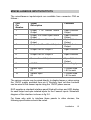
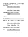
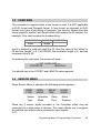
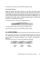
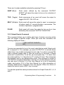
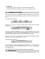
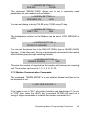
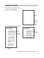
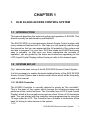
CHAPTER 1 1. ELID EL2200 ACCESS CONTROL SYSTEM 1.1 INTRODUCTION This manual describes the technical setting and operation of EL2200. This should normally be performed by qualified staff. The ELID EL2200 is a microprocessor based Access Control system with many advanced features built in. We hope you will patiently read through this manual so that you can appreciate the full potential of the system and are able to program it on your own. ELID has made the EL2200 extremely easy to program, so that once you have understood the principle of operation, you are guided by the menu and instructions appearing on the LCD (Liquid Crystal Display) without having to refer to this manual again. 1.2 SYSTEM SET-UP Fig 1 shows the basic set-up of the ELID EL2200 Access Control System. It is first necessary to explain the basic building blocks of the ELID EL2200 Access Control System and to define certain terms which will be frequently used in this manual. 1.2.1 EL2200 Controller The EL2200 Controller is normally referred to simply as "the controller". This is the heart of the system which houses the central processor and performs all the control functions. The Controller has a LCD (Liquid Crystal Display) which is like a small screen and can show 2 lines of 20 characters each. You can interact with the controller during programming by using the 16 keys under the LCD. The Controller has a number of connectors at the back for linking to other devices in the system. 1.2.2 ELID EL2200 Access Control System 1 Reader/Reader-Keypad Readers are for reading the ID number encoded on the identification card. Keypads are to allow users to key in their PIN code. Keypads are necessary when the more secure mode of operation, that is Card + PIN, is required. Most reader units are also equipped with status indications. ELID offers a wide range of readers which may be used in EL2200. Some of these are listed below:a) PIN Keypad ER3 - Matrix PIN keypad ER3S - Serial keypad with 4 seven-segment display b) Magnetic Readers ER5B - Magnetic swipe reader without PIN keypad ER5 - Magnetic swipe reader with PIN keypad ER5S - Magnetic swipe reader with PIN keypad and 4 sevensegment display ER4 - Magnetic insert reader, flash mounting ER4S - Magnetic insert reader with PIN keypad and 4 sevensegment display, surface mounting c) Wiegand Readers ER14 - Wiegand key insert reader ER15 - Wiegand swipe reader ER16 - Wiegand card insert reader d) Proximity Readers ER25H- Short range proximity reader ER27H- Mid range proximity reader ER29H- Long range proximity reader e) Bar code Readers ER35 - Bar code swipe reader with keypad ER35S - Bar code swipe reader with serial keypad and 4 sevensegment display ELID EL2200 Access Control System 2 f) Smart card Reader ER44 - Smart card reader, with Wiegand interface, flash mounting ER46S - Smart card reader, Wiegand interface, with serial PIN keypad & 4-digit LED display This manual does not contain an exhaustive list of all the readers, nor does it provide detailed technical information on how they can be connected to work with EL2200. Drawings for connection for readers will be found in the installation diagrams that accompany the readers. The most widely used reader is the magnetic reader. This reader can read codes encoded in a credit-card size magnetic card. There are 2 methods of reading, either by swiping the card down a slot (called swipe reader), or inserting the card in a slot, and then pulling it out (called the insert readers). Other types of readers are Wiegand readers - which use special wires buried in cards as coding bits; proximity readers - which are able to read codes without contact; bar code readers - which are based on standard bar-code technology; and smart card readers - which have IC's embedded in the plastic cards. Often, the reader unit comes equipped with a keypad similar to a telephone keypad. This keypad allows the user to key in the PIN (Personal Identification Number) code. This gives added security to the system in that the door will only open if the card plus the PIN code match, just like an ATM system. For some installations, there is both an entry reader and an exit reader. The entry reader is to gain access into the secure area whereas the exit reader is for coming out of the secure area. Sometimes, instead of an exit reader, a push-button is used. This exit push button is installed in the secure area. Users simply press the button to come out. Note that the exit reader is not equipped with a keypad since PIN codes are not necessary. The reader unit is usually equipped with either LEDs (Light Emitting Diodes) or 7-segment displays to indicate to users what is happening at the reader. ELID offers basically 2 types of readers, namely parallel type and serial type. Parallel type of readers are equipped with LED displays and require 14 wires. Serial readers are equipped with 4 seven-segment displays and require only 8 wires. ELID EL2200 Access Control System 3 For parallel readers, where LED's are used to indicate the status of the equipment, the display and their interpretation are as follows :Normal Red flashing, green off Valid card swiped Waiting for PIN entry Correct PIN entered Door is activated Invalid card or wrong PIN Both lights off Programming mode Both lights off. Green light on, Red light off Both red and green lights on. For Wiegand or Proximity Readers, if PIN keypad is not used, one indicator on the Reader itself will be used to display status. In normal condition, the light will blink. When a card is properly read and the door is activated, the light turns color and will remain steady. The exact color depends on the model. For serial readers using 4 seven-segment display, the indications for different status are as follows:E-RD If the card has unrecognizable codes, which may be due to swiping the card incorrectly, or damage to the card, the display will show "E-RD", which means Error - Read. E-CC - If the card's customer code does not match the controller's customer code, the display will show "E- CC", which means Error Customer Code. E-IC If the number is not found in the memory, the display will show "E-IC", which means Error - Invalid Card. E-CA of time, If the number is found in the memory, but the time zone category the card is such that it cannot enter the door at this particular the display will show "E-CA", which means Error - Category. ELID EL2200 Access Control System 4 E-NE not If the controller is set to "Inhibit Access" mode, then only certain category of users can gain entry. All cards of lower category will be granted entry, and the display will show "E-NE", Error - No Entry. E-AP If the controller is set to Anti- passback mode, and an antipassback violation occurs, the display will show E-AP. PIN If the controller requires PIN number to be entered. E-IP This indicates that an incorrect PIN number has been entered. GO This indicates that the door has been unlocked. 1.2.3 Door Sensor The door sensor is a device for detecting whether the door is open or closed. It is linked to the Controller. 1.2.4 Electric Door Lock The electric door lock is an electromagnetic device used to lock or unlock a door. When the device is "activated", the door can be opened. When it is "deactivated", it cannot be opened. There are many different types of door locks in use depending on the type of door it has to control. The door lock is controlled by the EL2200 Controller. 1.2.5 Miscellaneous Inputs/Outputs The Controller may optionally be connected to an interface panel where various types of alarm outputs, control outputs and status inputs are connected. These are briefly mentioned below. If your installation does not use these devices, ignore this section. a) Input Sensors : The EL2200 Controller has 2 input points that may be connected to other equipment to monitor their status. These points are referred to as Input Sensor Points #1 and #2. ELID EL2200 Access Control System 5 b) Outputs : EL2200 is equipped with 7 outputs. Out of these, 6 outputs may be individually programmed to be operated by any input condition. In addition, EL2200 can also operate in the EL2000 emulation mode, in which case, the 7 outputs are automatically configured as follows:I) GP Outputs (General Purpose Outputs) :2 output points may be connected to other equipment to control their operation. These 2 points are referred to as GP Output #1 and GP Output #2. I) Door Shunt Output :This is an output point which is activated each time there is a valid entry and will only deactivate when the door is closed. It can be used to shunt a door alarm contact monitored by a separate alarm system. I) Sensor Armed Output :The input sensors described previously may be used as burglar alarm inputs. In this case, you can arm or disarm the points. When the points are armed, the sensor armed output is switched on (activated). This point can only be connected to an LED indicator light. I) Duress Alarm Outputs :If the user is forced to open the door, (under duress) he can key in a special code which will cause the Duress Alarm Output to be activated. I) Door Open Alarm Output :If the door is forced open without using a card or exit push button or if a door is left open, the door open alarm output is activated. I) Sensor Alarm Output :If a sensor input is activated, then, unless the point is disarmed within the programmed delay period, the sensor alarm output is activated. This output is usually connected to a sounder to alert the occurrence of a break-in. 1.2.6 ELID EL2200 Access Control System 6 Power Supply The ELID EL2200 Access Control System operates on 12V supply, usually with a battery back up. The 12V power supply must have adequate charging capacity, with transient filtering and low-volt cut off. ELID offers EP33 speciafically for working with EL2200. 1.2.7 Printer Up to 64 EL2200 Controllers may be linked together by 4 wires to a printer for on-line printing (which means that every time something happens at the door, the printer will immediately print out details of the event) or once-aday printing or report printing. Note that you need to have a Communicator (such as EL71C Parallel Communicator) installed between the Communication bus and the printer. Depending on your requirement, you can choose EL71C, or EL72 Communicator. 1.2.8 Linking to Personal Computer Instead of a printer, you can link the ELID EL2200 System to a Personal Computer running ELIDsof 2000PRO software. This will allow you to perform a wide range of supervisory/control functions from the computer. The ELIDsof 2200PRO software will run on most IBM 286 / 386 /486 Personal Computers, or true compatible. 1.3 ELID EL2200 Access Control System 7 CARDS There are 4 types of cards used in ELID EL2200 Access Control System. Master Card : A unique set of master card is supplied with each Controller. This card allows the user to enter into the programming mode. Engineering Card : Certain programming functions are relevant only during installation and should not be tampered with thereafter except by engineering staff. The Engineering Card allows entry into engineering programming mode. Special Card : Holders of Special Cards are allowed to arm/disarm inputs and activate/deactivate outputs subject to valid card and valid time zone. User Card : These cards are issued to ordinary users. The above card distinctions apply to Magnetic cards, ELID-Hughes proximity cards and Bar-code cards. The cards are clearly printed with a 2letter identification to show which type they belong to. MC = Master card EC = Engineering card SC = Special card UC = User card For Wiegand and Proximity cards with standard 26-bit Wiegand format, only 2 fields of data are coded, the Customer code field and the ID (Identity number) field. Hence the usage of cards is slightly different. a) The Master card also acts as the Engineering Card. b) Cards with ID code less than 60,000 are automatically classified by the controller as User cards. c) Cards with ID code equal to or greater than 60,000 are automatically classified by the controller as Special Cards. 1.4 ELID EL2200 Access Control System 8 GETTING STARTED If you are using ELID EL2200 Access Control System for the first time, we would recommend that you borrow or purchase an EL2200 Demonstration Set which comes fully wired with the following :* Miniature door with electric lock, door knob and door contact * EL2200 Controller * ER5S Magnetic Reader/Keypad * Power supply and battery backup (2.4AH/12V) * EL70B Communicator * ELIDsofPRO software * Full set of manuals This will allow you to learn the programming operation of the equipment immediately. you will also be able to confirm the connection requirement by checking the drawings given in chapter 2 with that implemented on the demonstration set. 1.5 PROGRAMMING 2 sets of programming are required to put an ELID EL2200 system into service. The first set is referred to as Engineering Programming and the second as User Programming. You should perform Engineering Programming first as described in chapter 3 of this manual. After that you should perform User Programming as described in chapter 3 of the User Manual. When you are happy with all the settings you have entered, you should save the values in the EEPROM by performing the Save Parameter Command described in section 3.6 of this Manual. ELID EL2200 Access Control System 9 CHAPTER 2 2. INSTALLATION This chapter describes the wiring arrangement and the installation procedure. You should begin by removing the cover of EL2200 Controller by releasing the screw at the bottom of the Controller and lifting the cover from the bottom end. Note that you also need to remove 2 connectors, one for the LCD and one for the membrane switch. Note the orientation of the connectors when you remove them so that you will know how to fix them back. In order to mount the Controller base plate to the wall, you need to remove the Controller PCB by removing the 4 nuts holding it. Note that 6 groups of wires come into the Controller (see fig 2.1). The detailed wiring of these 6 groups are discussed below :- 2.1 READER AND KEYPAD INSTALLATION EL2200 can support 2 types of "IN" readers, referred to as parallel readers and serial readers, irrespective of whether they are magnetic, Wiegand, Bar-code, Proximity, Smart card, or whether they are of the insert type or swipe type. The parallel type uses a matrix keypad (7 wires) and a reader with 2 LED display (7 wires). Hence the total number of wires is 14. The keypad wires are connected to CN12 and the reader wires are connected to CN8. For example, ER5 is a parallel reader. Installation 10 The serial type uses extra electronics to multiplex keypad reading and 4 seven-segment display functions. The entire unit only uses 8 wires and must be connected to CN7. All reader/keypads with the suffix -S (e.g. ER5S) belong to this type. Note that only the "IN" reader can have the option of using serial reader. The "OUT" reader is always a parallel reader and connected to CN9. 2.1.1 Magnetic Reader/Keypad ( Fig 2.1 & Fig 2.2 ) ER5, ER5S, ER5B Magnetic Reader/Keypad are meant for surface mounting. Select a location near the door with sufficient space for a person to swipe his card without obstructing the door passage. The reader should be installed at a convenient height from the floor. Ensure that wiring from this unit to the EL2200 Controller is not unnecessarily difficult and obstructed. Dismantle ER5 by removing the bottom screw and lifting up the cover from the bottom end, as the top end is hooked to the base, and cannot be removed until the bottom part of the cover is lifted up. You may completely dismantle the cover by unplugging certain connectors. Note the orientation of the connectors, so that when you connect them back, you will not make a mistake. The wiring from ER5 Reader to EL2200 Controller is as shown in fig 2.1 and Fig 2.2. Fig 2.1 is too large to put into one page, so it is split into 2 drawings, labelled as Fig 2.1 /1 and Fig 2.1 /2. Note that the color of the wires follow the standard resistor code, so that there is less chances of making a mistake. There are 2 separate cables, each with 7 wires. One of them, marked "K" is for connecting the keypad, and should be screwed in to CN12 on the EL2200 controller. The other cable, marked "R" is for the "Entry" reader, and should be connected to CN8 on the EL2200 controller. Installation 11 The wiring for ER5S serial reader is also shown in fig 2.2b. There is only 1 cable of 8 wires provided in the reader. You should connect the 8 wires to CN12. Note that this cable is provided by ELID and is 6 ft long. It is not advisable to extend this cable because of interference and cable impedance matching. If you need to mount the reader more than 10 feet away, make a new cable using 8-core shielded, non-twisted cable. You can also purchase such cables from ELID. Note that you cannot use ER5 and ER5S simultaneously as the "entry" reader. You must choose either ER5 or ER5S. The wiring for ER5B exit reader is shown in fig 2.1. This reader has no keypad, since there is no necessity for using PIN on exit. Thus, there is only 1 cable of 7 wires, and this is connected to CN9. 2.1.2 Wiegand Reader (Fig 2.3) Wiegand Readers such as ER14, ER15 etc. have only 5 wires instead of 7 wires. The wiring diagram for Wiegand Readers is shown in fig 2.3. Depending on the model, the cable color may differ. You should check the signal name (5V, GND, DATA0, DATA1, LED) before making the connection. 2.1.3 Proximity Reader (Fig 2.4) Connection diagram for different models of ELID-HUGHES Proximity readers to EL2200 is given in fig 2.4(a), (b) and (c). Other brands of Proximity Reader can also work with EL2200 provided they use Wiegand interface. In such cases, identify the signal names (V+, GND, DATA0, DATA1, LED) and wire them according to signal names. It is necessary to check the voltage and current required for the proximity reader. If the voltage is 12 volts, follow the wiring of fig 2.4(b). Ensure that current taken by the reader is not more than 0.3A at 12V. If the current rating exceeds the above, or if the reader requires 24V, then you should provide a separate linear power supply (Fig 2.4(c)). Follow carefully the installation precautions of the manufacturer of the reader, otherwise, you may not be able to achieve the range specified. 2.1.4 Installation 12 Keypad Interface ELID provides ER3 parallel keypad and ER3S serial keypad for use with Wiegand and proximity readers. The wiring is as shown in fig 2.5(a) and fig 2.5(b). If you are using your own keypad for linking to CN12 Connector on EL2200, the keypad must be of the Matrix type with connection as in fig 2.5(a). 2.2 ELECTRIC DOOR LOCK, DOOR SENSE AND EXIT PUSH BUTTON-INSTALLATION The electric door lock is activated by a relay located on the PCB. In EL2000 series, a 12V supply is available from the relay contacts. This is NOT so in EL2200, which gives volt-free contacts. The relay contact "common" is connected to CN3 pin 2 and the Normally closed (NC) contact to CN3 pin 1. The Normally open (NO) contact is connected to CN3 pin 3. Hence fail-secure locks should be connected across pins 2 and 3 and then in series with the power supply and fail-open locks should be connected across pins 2 and 1 and then in series with the power supply. This power must be taken from the power supply and not from EL2200. (See Fig 2.1b). Ensure that you provide a surge suppression device across the electric lock, such as a diode (if DC supply is used) or a varistor or capacitor (if AC supply is used). If you should choose to use a diode for spike suppression, ensure that the polarity is correct. Although the relay contact is rated at 3A, we recommend that you keep the maximum current to not more than 1.0A. The door sensor (door contact) wires should be connected to CN3 pins 4 and 6. Note that CN3 pin 4 is at 12VDC. The exit push button should be connected between CN3 pin 4 and CN3 pin 5. It should be a normally open contact. Note the type of door contact you have installed. EL2200 is factory set to read door-open-contact-open type of door sensor. If it is of the reverse type, you will have to change the setting according to the procedures Installation 13 described in section 3.1.3.If you do not need an exit push-button, do not wire it in. 2.3 Installation 14 MISCELLANEOUS INPUTS/OUTPUTS The miscellaneous inputs/outputs are available from connector CN2 as follows :CN2 Pin Number 1 Signal Description Comment 4 Output 1 or Duress Alarm Output Output 2 or Door Open Alarm Output Output 3 or Sensor Alarm Output Output 4 or Door Shunt Output 5 Output 5 or GP Output 1 Open Collector Output Open Collector Output Open Collector Output Door Collector Output Open Collector 6 Output 6 or GP Output 2 Open Collector 7 Sensor Armed Output 8 12VDC Open Collector Output Power Supply 9 Sensor Input #1 Sensor Input #2 13 Kohm load > 8V to work 13 Kohm load > 8V to work 2 3 10 The various outputs may be wired directly to display lamps or relays using the 12VDC supply provided from pin 8. Similarly input volt-free contacts can be wired to the sensor inputs using the 12VDC power source. ELID supplies a standard interface panel fitted with relays and LED display for each output and opto-isolated inputs for the 2 sensor inputs. Schematic diagram of this interface is shown in fig 2.6. For those who wish to interface these panels to other devices, the following specifications should be noted. Installation 15 a) Open Collector Output has maximum sinking capacity of 200MA. Maximum voltage that can be applied externally is 35VDC. b) For sensor inputs, the input impedance is 13 Kohm. Minimum voltage needed to guarantee sensor alarm activation is 8VDC. c) 12VDC available at pin 8 has maximum current rating of 0.3 Amp. 2.4 POWER SUPPLY The power supply required by EL2200 is 12VDC. It must be fed into connector CN10 pins 5 and 6. Positive end is to be connected to PIN 5, and negative end is to be connected to PIN 6. A fuse rated at 1A is connected immediately after this and feeds all other devices. Note that the 12VDC available at CN2/pin 8 and CN3/pin 4 are merely rectified and smoothed voltage from the input supply. 2.5 WORKING WITH PRINTER OR PC EL2200 has a serial port available at pin 1, 2, 3, 4 of connector CN10. This port is configured as a multidrop and hence can be wired in parallel with up to 16 Controllers. The serial port allows EL2200 to be connected to a printer for direct print out in the stand-alone mode or to a PC running software such as ELIDsof for centralized supervision and control. In either case, you will require a communicator to convert the multidrop signals to RS232 signals, or parallel printer signals. ELID offers many different models of communicators. The purpose of the communicator is to convert the multidrop signals to RS232 signals. Choice of which type of communicator to use depends on 2 factors:a) Number of buses, with each bus capable of taking 16 controllers. b) Whether PC or Printer is required. Installation 16 For stand-alone operation with printer, you should choose EL71C for one bus (16 controllers) and EL72 for 4 buses (64 controllers). For network operation with PC, you should choose EL70B for 1 bus (16 controllers), EL75 for 2 buses (32 controllers) and EL72 for 4 buses (64 controllers). 2.6 POWERING UP After you have completed wiring as detailed in the previous section, you are now ready to switch on the power. Before doing so, check the wiring once more. Particularly those in relation to power lines (e.g. CN8/pins 1 and 5 for entry reader power supply, CN9/pins 1 and 5 for exit reader power supply, door lock output CN3/pins 1,2 & 3, CN10/pins 5 and 6 for incoming power supply, CN2/pin 8 for sensor/output power supply). Mistakes in power supply wiring can damage the board electronics. Ensure that you have used the right socket. Put back the Controller cover and switch on the supply. If the fuse blows, you should check your wiring again and ensure that you clear the fault before switching on again. If this is the first time you are switching on the power, you need to perform a "cold start". This is done by holding down buttons F1 and F2 simultaneously while switching the power on. Do not release the F1 and F2 keys until the beep sound is heard, and the display is blank. Immediately upon releasing the 2 keys, the display will show :MAST CARD ENG. CARD CARD TYPE DISP TYPE If you press the <NEXT> key, the screen changes to :EL2000 MODE CONT. SWIPE Pressing the <NEXT> key brings you back to the first screen. Installation 17 The keyboard used on EL2200 consists of 16 keys, most keys have dual functions. A brief description of the use of the keys follows. The keys 0-9 are used for entering numbers as well as letters A-Z. The keys <ESC>, <ENTER>, <F1>, <F2>, <F3>, and <F4> are function keys. F1 to F4 Keys are used for menu selection. Often you will see 4 menus being displayed on the LCD screen, one menu above each of the 4 function keys. Hit the key directly under the menu you want. F1 to F4 Keys are also used during data entry for UP/DOWN scrolling of screen and LEFT/RIGHT manipulation of cursor, as shown by the arrow signs on these keys. The Key <ENTER>, located at bottom right hand corner is for confirming data entry. The key is also used to display the "NEXT" screen, when a menu has more than 4 choices and therefore cannot fit into a single screen. The <ESC> or ESCAPE Key is used for aborting a data entry and also for escaping to the previous level of menu. Thus pressing it a number of times will cause the program to exit from the program mode and return to the run mode. Press F1 key which is right under "MASTER CARD" command, in order to set the master card number. The display will show :>> EL2200 SET-UP << MASTER CARD:000000 The blinking cursor is pointed to the first "0". You should now key in the 6digit master card number followed by the <ENT> key. For example, if the master card has the following marking:MC 01 9999 920258 The number you need to enter is “920258” followed by <ENT>. If you make a mistake, you can correct it by the "<-" key. After you have pressed the <ENT> key, the display will go back to the original menu screen. Installation 18 Press F2 key in order to set the Engineering card number. The display will show :>> EL2200 SET-UP << ENG. CARD :000000 You should key in the Engineering card that is used by your company, ending with <ENT> key to return to the main menu screen. Press F3 key to choose the type of reader and card format you wish to use. >> EL2200 SET-UP << CARD TYPE ELID You can change the card type by pressing "F4" key repeatedly. The various types of readers that you can select are :ELID ABA BAR WIEG PROX - Magnetic reader with ELID card format. Magnetic reader with ABA card free format. Bar code reader, 2 of 5 interleaved ELID format and 3 of 9 format. Wiegand reader, with 26 bit Wiegand format. Proximity reader, with ELID format. Depending on the type of readers you are using, you should set to the appropriate card format. For example, the Wiegand format is used not just for ER15 Wiegand readers, but also Smart card readers (ER44 and ER46D), and certain Proximity readers. When the desired setting is shown, press <ENT> key to accept. Press F4 to select "7-SEGMENT DISPLAY" command. The screen will show:>> EL2200 SET-UP << 7-SEG DISPLAY YES If you are using 7-segment display such as ER5s, leave the answer as YES. If you are using matrix keypad with LED display, then press "F4" once, and the "YES" will change to "NO". Press <ENTER> key to accept the setting. Installation 19 Press <NEXT> key from the main screen, and the display will show the remaining 2 commands of the set up menu, that is "EL2000 MODE" and "CONTINUOUS SWIPE" mode. Press "F1" to select "EL2000 MODE" command. The screen will show :>> EL2000 ALARM OUTPUT << EMULATION NO You can toggle between "YES" and "NO" by repeatedly pressing F4 key. When the setting shows the value you desire, press <ENT> key to accept. If you have chosen "YES", it means that outputs the 6 outputs will emulate EL2000, being used for duress alarm, door open alarm, door shunt, sensor alarm, and sensor armed. If you have set to "NO", then these outputs are General purpose outputs that can be programmed to operate when certain input conditions occur. You can also select whether you want to allow "continuous swiping" or not. If it is set to yes, it means that you are allowed to swipe even when the door is open. If the setting is "NO", then the reading is disabled until the door is closed. After finishing the above set-up, you should press "ESC" key from the main screen to exit. The display will show :** EL2200 VER X.X ** >>Initialize System After about 30 seconds, the date/time should appear on the LCD and the red light on the reader should begin to flash. You should now proceed to the diagnostic tests described in section 3.3 to check that the readers, keypads, door lock, door contact, printer or PC, input sensing points, output control points etc. are all working correctly. Once initialised, the controller will accept the Master card and Engineering card programmed into it and you can proceed according to chapter 3 to program the unit according to your requirement. 2.7 Installation 20 EL2200 CONTROLLER BOARD The essential features of this PCB are shown in fig 2.7. Note the following indicator lights :* The serial transmission monitoring lights - red for transmit and green for receive. When connected to an active communicator, the green LED is always ON, while the red LED will blink when the controller sends data back to the communicator. * Power supply on lamp - to indicate the presence of 12V supply. * Door lock relay LED - to indicate activation of the door lock. * CPU running indicator light - This LED may blink according to the portion of program which is being executed. There is a preset for adjusting the brightness of the LCD display. A CPU reset switch is located at the top right hand corner of the PCB. This is for resetting the CPU. Installation 21 CHAPTER 3 3. ENGINEERING MENU AND PROGRAMMING PROCEDURES To enter into the programming mode, you should swipe the Master Card and key in the PIN Code. Use PIN #2 if the card is magnetic. For other cards, there is only 1 PIN Code. The PIN Code is usually given on a sheet of paper that is packed together with the Master Card. If you are using the IN reader to swipe the Master Card, the door lock is activated to allow you to get into the room where the Controller is located. If you are using the OUT reader, the lock will not be activated. The screen will display :USER MENU ENG. MENU User Menu contains commands for normal operation, and are described in the USER Manual. Engineering Menu contains special set-up commands which are only used by technical staff. This chapter describes all commands in the Engineering Menu. Press the <F2> Key to select the Engineering Menu. The screen will display : ENGINEERING MENU SWIPE ENG. CARD Engineering Menu & Programming Procedures 22 You should swipe the "ENGINEERING CARD". If the card is not valid, the screen goes back to the previous one, displaying the USER MENU and the ENGINEERING MENU. If the correct card is swiped, the following display appears :DOOR CARD SENS OUTP MENU MENU MENU MENU Pressing the <NEXT> Key will display another 4 menus :COMM. MENU MODEM MENU TEST MENU SAVE PARA Pressing the <NEXT> key will show the last command :CLEAR MEM You can switch from one screen to another by repeatedly pressing the <NEXT> Key. 3.1 DOOR MENU Select DOOR Menu by pressing the <F1> Key which is the key just underneath DOOR MENU. You will notice that the screen changes to :L-R TIME | S-AC TIME | DOOR SENS | PUSH BUTTN | Lock Release Time Shunt Door Activation Sense Time Setting Push Button Setting Pressing the <NEXT> key will show another 2 commands :3.1.1 PIN SEL PIN ENTRY Engineering Menu & Programming Procedures 23 Lock Release Time Press the <F1> Key to choose Lock Release Time Setting Command. The display now shows :>> SET L.R TIME << 005 SECONDS Lock release Time is the time duration that you want the electric door lock to remain operated each time it is commanded to turn on. If the door is not opened during this delay time, the door lock will be deactivated and the user cannot open the door unless he swipes his card again. This value is factory set to 005 seconds, but you can change it to any value between 001 second and 200 seconds. Values outside the above range will not be accepted by the Controller. Note that you must enter 3 digit numbers. Hence, 3 seconds must be keyed in as 003 followed by the <ENTER> Key and not 3. The screen then returns to the DOOR Menu display. Note also that you can correct your entry by using the <BACKSPACE> (<F3>) Key. Pressing the <ESC> Key causes the Command to be aborted. 3.1.2 Shunt Activation Time From the DOOR Menu display of section 3.1, pressing the <F2> Key will execute the Shunt Activation Time Command. The LCD will display the following :Set Door Parameter >> SET DOOR PARAM << SHUNT ACT TIME *1 | | Shunt Output Multiple of Activation Delay Lock Release Time Time Engineering Menu & Programming Procedures 24 Each time the door is validly open - as when a valid card is swiped, the Door Shunt Output is activated. The duration of activation may be set as a multiple of the Lock Release time. The multiplication factor can be *1, *2, *4, *8. For example, if the Lock Release Time is set to 5 seconds and the Shunt Activation Time is set to *2, then the Door Shunt Output will be activated for 10 seconds each time a valid door entry occurs. In practice, the Door Shunt Output is used to prevent the triggering of alarm if the same door is wired to an independent burglar alarm panel. In order to change the multiplication factor, press the <F4> Key. Each time the <F4> Key is pressed, the value changes. When the desired value is shown on the screen, press the <ENTER> Key to accept. 3.1.3 Door Sense From the DOOR Menu display, press the <F3> Key. The screen display will show the following :>> SET DOOR PARAM << DOOR SENSOR OPEN This command allows you to select the type of Door-Contact you wish to use, either Door-Open-Contact-Open or Door-Open-Contact-Closed. The Factory setting is Door-Open-Contact-Open (meaning, the sensor contact is open circuit when the door is open; which also implies that the sensor contact is shorted when the door is closed) You can change it to the opposite type, which is Door-Open Contact-Closed by pressing the <F4> Key, which causes the display to change to CLSE and accept it by pressing the <ENTER> Key. 3.1.4 Push Button In many applications, only the IN reader is installed, there is no OUT reader. Instead a push button is connected, which when pressed will cause the door lock to be activated. When the Push Button Command is selected, the display will show :>> SET DOOR PARAM << PUSH BUTTON ON Engineering Menu & Programming Procedures 25 The factory setting is "ON", meaning that opening door by the push button is allowed. Pressing the <F4> Key will cause the display to toggle between "ON" and "OFF". If push button exit is disallowed, you should press the <F4> Key until the display shows "OFF", then press ENTER> Key to accept. 3.1.5 PIN Select Return back to the DOOR Menu as follows :L-R TIME S-AC TIME DOOR SENS PUSH BUTTN Press the <NEXT> Key to display additional menu :PIN SEL PIN ENTRY Note that you can go back to the first screen by pressing the <NEXT> Key again. When the screen shows PIN SEL, press the <F1> Key to select the command. The following display will appear :>> SET DOOR PARAM << PIN COMPARISON PIN 2 This shows that the second PIN Code is chosen. PIN 2 is the factory setting. You can choose to use the other PIN Code (PIN 1) by pressing the <F4> Key followed by the <ENTER> Key. PIN 1 is user definable and PIN 2 is pre-defined. In other words, if you choose PIN 1, you can select your own PIN number for each card. If you choose to use PIN 2, then the PIN is calculated by an algorithm supplied by ELID. 3.1.6 PIN Entry The PIN entry command allows you to set whether you wish to have the facility of opening the door by PIN number (without card). EL2200 allows you to predefine up to 10 such numbers which can be used to open the door. Engineering Menu & Programming Procedures 26 When the command PIN ENTRY is chosen, The display will show :>> SET DOOR PARAM << PIN ENTRY NO You can set to "YES" by pressing F4. 3.2 CARD MENU Go to the main menu screen :DOOR MENU CARD MENU SENS MENU COMM. MENU and press the <F2> Key to choose Card Menu Command. The display will show :DB USER CARD MODE SIZE SIZE Data Base Mode User Database Size Card Offset Choose DB Mode by pressing the <F1> Key. The display shows :>> SET DBASE PARA << CARD WITH NAME NO This command allows you to choose whether the Controller should store name of each card or not. If name is to be stored, you can have 12 characters (including space) per name. The table below shows the options available and the number of Users that can be accomodated :- Engineering Menu & Programming Procedures 27 Mode No Of Users Card ID Card ID + Programmable PIN Card ID + Name Card ID + Programmable PIN + Name Normal 1600 1150 480 430 Extended 3200 2300 960 860 Note that the number of users is determined by the following factors :a) Whether Programmable PIN (PIN1) is set. b) Whether name is required for User Card. c) Whether the data base is set in normal or extended mode. Press the <F4> Key to choose "YES" or "NO" and accept the choice by pressing the <ENTER> Key. To set the Transaction data-base size, press the <F2> Key, and the following display appears :>> SET DBASE PARA << USER DB SIZE NORM If extended card database is to be chosen, you should press the <F4> Key causing the display to change from "NORM" (Normal) to "EXTD" (Extended) followed by the <ENTER> Key. In the normal mode, 2000 transactions are saved. In the extended mode, only 1000 transactions are saved. Note that in the extended mode, the size of the log buffer which stores transaction is reduced to make room for more card users. WARNING : Changing of any of the above parameters will cause card database and transaction database to be erased. Hence DO NOT make any alterations once the system is already set up. Engineering Menu & Programming Procedures 28 3.3 CARD SIZE This command is required when a free format is used. It is NOT applicable to ELID format and Wiegand format. A free format, as opposed to ELID format, may have a long string of numbers. You need to choose from this string a specific position, and length which will become the ID number. For example, if the card contains the number string :12345678 offset 9 0 1 2 3 4 5 6 7 8.9 length And it is desired to read only digit 9 to 13, then the value of the "offset" is 08 and the "length" is 5. For EL2200, the maximum length is 6, and the maximum offset is 40. On entering this command, the screen will show :>> SET CARD SIZE << OFFSET:00 LENGTH:6 You should key in the OFFSET and LENGTH value required. 3.4 SENSOR MENU When Sensor Menu is selected, the following screen appears :SENS OPRN DELAY TYPE MODE TIME | | | Sensor Operation Delay Type Mode Time ALRM DURN | Alarm Duration There are 2 sensor inputs provided in the Controller which may be connected to a wide range of devices. This menu allows you to program the method you wish to use to process the input signals. 3.4.1 Engineering Menu & Programming Procedures 29 Sensor Type The first command, Sensor Type is accessed by pressing the <F1> Key whereupon the following screen will appear :>> SET SENSOR PARAM << #1 SENSOR TYPE NC | | Sensor Input Number NC = Normally Closed Contact NO = Normally Open Contact If the signal comes from a device whose contacts are normally closed in the non-alarm state, you should set the parameter to NC. If it is normally open, you should set to NO by pressing the <F4> key followed by the <ENTER> Key. The setting for the second sensor input will now appear which you can program in the same way. 3.4.2 Operation Mode The second command, Operation Mode. is accessed by pressing the <F2> Key. The display will show :>> SET SENSOR PARAM << #1 SENSOR MODE STAT Sensor Input Number STAT=Status ALRM=Alarm INHB=Inhibit A Sensor Input can be processed as a Status Input or an Alarm Input or an Interlock Inhibit input. A Status Input (such as MOTOR ON/OFF) can be in either states both of which are normal in operation. An Alarm Input (such as a Motion Detector) however is normally in non-alarm state and when it goes to the other state, it is in an abnormal condition and must cause the Sensor Alarm Output to be activated. (which would normally be connected to a Sounder) Engineering Menu & Programming Procedures 30 An alarm output can be "armed" (in operational state) or "disarmed" (in non-operational state) by the user. Inputs can be excluded (Removed from service) or "included" (put into service). These are described in the User Manual. When you wish to interlock the Reader with another door, you are linking the operation of the two doors. in other words, you wish to disable the Reader operation when another door opens, You can do this by using the Interlock Inhibit input. When programmed in the Inhibit mode, each time the sensor input is activated, the Reader will not open the door even when a valid card is swiped. An example is shown in Fig 3.1 where 2 doors, both controlled by EL2200 are interlocked. To select the operational mode, press the <F4> Key, and when the display shows the desired setting, press the <ENTER> Key to accept. The screen will now show the operational mode of the second Sensing Input. Use the <F4> Key to make selection and press the <ENTER> Key to accept. 3.4.3 Delay Time The third command for setting sensor input parameter is Delay Time Setting. Press the <F3> Key and the screen will show :>> SET ALRM TRI.DLY << DELAY 1:00 DELAY 2:00 Delay in seconds Delay in seconds for Sensor Input 1 for Sensor Input 2 Delay Time is only applicable for alarm point and irrelevant to status point. If for example, a delay of 10 seconds is set for Sensor Input #1, which is programmed as an alarm point, then when the point is armed, it will become operational 10 seconds from the time of arming. When an abnormal condition occurs, it will also wait for 10 seconds before activating the Sounder. A point which is excluded cannot be armed. To set the desired Delay Time, key in the value (in 2 digits) which may be any from 00-99 seconds and press the <ENTER> Key. Engineering Menu & Programming Procedures 31 This function is only active in the EL2000 emulation mode. 3.4.4 Alarm Duration When the sensors are armed, and there is an alarm, the sensor alarm output will activate. This sensor output is normally connected to a sounder. The duration of activation of the sounder can be set by this command. If it is set to 000, the sounder will continue until the sensor is disarmed. If it is set to say 300 seconds, then the sounder will continue for 300 seconds or 5 minutes. If the input sensor is still not disarmed after 5 minutes, the sounder will automatically be turned off. On entering into this command, the display will show :>> ALARM DURATION << 000 SECONDS You can set the duration to any value up to 999 seconds. This function is only active in the EL2000 emulation mode. 3.5 OUTPUT MENU The Output Menu consists of 3 commands associated with the control of the general purpose control output points. These output points may be used to switch on electrical equipment such as lights, air-conditioners, pumps etc. On entry into this menu, the screen will display the following :OUTP TYPE OUTP EVENT Output Type Output Event OUTP DURN Output Duration Engineering Menu & Programming Procedures 32 3.5.1 Output Type If the "OUTPUT TYPE" command is selected, the screen will show :>> OUTPUT SELECT << #1 TYPE GP If you press "F4", the display will change from “GP” (general purpose) to "EVNT" (event). In the GP (general purpose) mode, the output can be activated manually by means of a special card, or from a PC or by a timer. In the EVNT (event) mode, the output is also activated by an input event, which may be any of the transaction codes recognized by the unit. As before, set the display to the mode you desire by pressing F4 key, and then accept the selection by pressing the <ENT> key. The second output point is now presented. Repeat the same procedure to set the mode for output point #2. If during the initial SET-UP, you have set the unit to EL2000 OUTPUT EMULATION mode, then only outputs 1 & 2 can be set, since the other 4 outputs are predefined as Duress alarm output, door open alarm output, door shunt output and sensor alarm output. If during the initial SET-UP, you have not set the unit to EL2000 OUTPUT EMULATION mode, then, all the 6 outputs can be set. Thus, you can continue to set OUTPUTS #3, #4, #5, and OUTPUT #6 as a GP point or Event point. If you have selected "GP" mode, the setting is complete, however, if you have selected any of the point to "EVNT" mode, the display will now show :>> OUTPUT SELECT << #1 PATTERN SHRT Engineering Menu & Programming Procedures 33 There are 4 modes available (selected by pressing F4 key) : SHRT (Short) Each event, defined by the command "OUTPUT EVENT" will cause the output to turn on for a duration of 1.. second. TOG (Toggle) Each occurrence of an event will cause the output to toggle ON..OFF..ON..OFF etc . MULT (Multiple) Each event will cause the output to send a succession of pulses, each of 1 second duration in succession. The number of puslses is programmable. PULSE Each event will cause the output to turn on for a time defined by the command "OUTPUT DURATION". 3.5.2 Output Events Command This command allows you to define what type of activity occurring at the door will trigger a specific output. When you enter this command, the following display will show :> DEF OUTPUT EVENTS < #01_ You are now expected to key in the event code that you wish Output point #1 to respond to. If for example, you want OUTPUT #1 to activate when either there is an invalid card swiped (event code 1) or when a wrong PIN code is entered (event code 3), then you must key in the code 1 (invalid card) and 3 (invalid PIN). To do this, you must press key "1" 4 times, then the cursor-right key "->", then the key "3" a total of 4 times. This is because the keypad is now in the alphanumeric mode. This command is similar to LOG EVENT command described in Section 4.5 of User Manual, and you can refer also to Section 2.3 of the User Manual for a list of transaction codes, and section 3.2.4 of the User Manual for a fuller description of entering alphanumeric characters from the keypad. When the choice of events are correct, press <ENT> key to accept. You should repeat the same procedure above for Output Points #2, 3, 4, 5 and 6. Engineering Menu & Programming Procedures 34 Note that if you have chosen any of the points to be "GP" instead of "EVENT", then this command will have no effect on those points. 3.5.3 Output Duration Command The "OUTPUT DURATION" command is to set the duration for which the output point is to stay activated when it is set to the "PULSE" mode. You may set the value from 0 to 999 seconds, individually for each of the 6 outputs. Note that this command will only act on a point that has been set to "EVENT" mode (as opposed to "GP" mode") and to "PULSE" mode (as opposed to "SHRT", "MULT" or "TOG"). On entering this command, the screen will show :#1 > OUTPUT DURATION < 999 SEC Enter in the desired value and press <ENT> to accept. Repeat for Output #2 TO #6 . 3.5.4 Example Of Using EVENT Mode Suppose it is desired to use EL2200 as a time recording terminal, with a buzzer/light to indicate correct swipe and a different buzzer tone for indicating an incorrect swipe. This can be done by using EL2200 with 2 readers, the entry reader for workers coming to work and the exit reader for workers going home. Also connect a buzzer (or green light) to Output #1 (CN2 pins 8 & 6) and another buzzer (or RED light) to Output #2 (CN2 pins 8 & 7). a) LOG EVENT command set this to "0" and "9" so that only valid entry and valid exit are logged. (See section 5.4 of User manual). b) OUTPUT 1 under "OUTP TYPE" command - set to EVENT mode, SHRT under "OUTP EVNT" command - set to "0" and "9" for valid entry and valid exit. Engineering Menu & Programming Procedures 35 c) OUTPUT 2 under "OUTP TYPE" command - set to EVENT mode, MULT under "OUTP EVNT" command - set to "1" for invalid entry/ exit. 3.6 COMMUNICATION MENU This menu which has 2 commands allows the baud rate of the serial communication and the identification number (1-16)of the Controller to be set. The screen looks like this :BAUD RATE UNIT NO ENCR MODE Press the <F1> Key to choose the Baud Rate Setting and the screen changes to :>>> SET COMM. PARA <<< BAUD RATE 2400 The factory setting is 2400 bauds. You can change the baud rate to any of the following 600, 1200, 2400, 4800 by pressing the <F4> Key. When the desired setting is displayed, press the <ENTER> Key to accept. Press the <F2> Key to choose Unit No. This is the identification number and may be set to any value between 1 and 16. The screen looks like this :>>> SET UNIT NO <<< 01 Key in the desired number followed by the <ENTER> Key. For example, to set the Controller to the identification address of 13, key in 13 and press the <ENTER> Key. For `ENCR MODE’ or Encryption Mode setting, see Appendix 1. 3.7 MODEM MENU Engineering Menu & Programming Procedures 36 This set of 8 commands allows you to set up EL2200 so that it can be located in an unmanned remote station, with control remotely sent via modem from a central office via standard telephone lines. In using such a set-up, you need to connect EL2200 to a suitable communicator such as EL70T and then to a Hayes compatible Modem. The modem is then connected to a public phone line. At the Central station, you will need to have a PC running ELIDsof 2000PRO with a modem software. The central office, through the PC software is able to dial up the remote EL2200, and communicate with it. It will be able to perform all programming functions just as if the EL2200 is directly connected to the central office by wires. Furthermore, when there is an abnormal event occurring at the remote site, the EL2200 is able to dial back to the central station, and report the alarm. Fig 3.2 shows a typical set up of such an installation. On entering this menu, the following commands are displayed in 2 screens. Screen #1 Screen #2 MODM MODE MODM ID TEL NO Modem Mode Modem Identity Telephone Number RETRY T.OUT DEF TRAN MODM PARA Retry Time NO RETRY Number of Retry PROG MODM Define Modem Program Transaction Parameter Modem 3.7.1 Modem Set-Up Commands The command "MODM ID" is to allow you to set the Modem identity so that the central station can recognize which site has called back. >>> SET PHONE NO <<< #1_ Engineering Menu & Programming Procedures 37 You can enter in up to 6 alphanumeric characters. The command "TEL. NO" allows you to key in up to 4 alternative phone numbers that EL2200 will sequentially dial when an alarm occurs. >>> SET NO OF RETRY <<< _ You can key in up to 16 digits of alphanumeric characters for each phone number. If EL2200 fails to connect with the central station using the first number, it will attempt the second and so on. The command "NO RETRY" allows you to set the number of retries in the event that connection fails. _ >>> SET TIME OUT <<< SECONDS The maximum number of retry is 10. The command "RETRY T. OUT" sets the duration in seconds that EL2200 will wait for a response from the central station before it retries the connection. >>> SET MODEM ID <<< _ The maximum setting is 999 seconds. The command "DEF TRAN" defines the transaction codes that can cause the EL2200 to dial back to the central station. For example, if door force open alarm (code 4) and wrong PIN (code 3) are to cause dial back to central station, then the values "4" and "3" must be entered into the data field. Up to 16 codes can be defined. Define Automatic Call Back EVENTS Engineering Menu & Programming Procedures 38 >> MODEM SETTING << DIALING PULSE The command "MODM PARA" allows you to set 4 commonly used parameters on your modem unit as follows :>> MODEM SETTING << SPEAKER VOL. LOW You can set dialing to be by PULSE or by TONE using F4 key. >> MODEM SETTING << LINE TYPE DIAL The loudspeaker volume on the Modem can be set to LOW, MEDIUM or HIGH. >> MODEM SETTING << RINGS TO ANSWER 1 You can set the phone line to be DIAL-UP (DIAL) type or LEASE (LEAS) line type. In the later case, the line is permanently connected to the central office without going through switching network. >> MODEM SETTING << ENABLE MODEM YES This sets the number of rings before the modem will intercept an incoming call. The number can be set to 1, 2, 3, 5, 8, 10, 20. 3.7.2 Modem Communication Commands The command "MODM MODE" is to set whether Modem facilities are to be activated or not . >> DEF ACB EVENTS << _ If the mode is set to "NO", all modem functions are deactivated. If it is set to "YES" then, when the <ENT> key is pressed, EL2200 will send out a string of Hayes commands to initialize the modem connected to it. Engineering Menu & Programming Procedures 39 The command "PROG MODM" allows you to send whatever commands you wish to send to the modem. In this mode, EL2200 behaves like a terminal. >> TRANSPARENT MODE << _ 3.8 TEST MENU This menu is used for diagnostic test of the hardware of the system and is useful when you are doing trouble-shooting at site. Eight diagnostic tests are available under this menu allowing testing of Keypad, Reader, Input, Output, 7 Segment, Communication, Memory and Program. The seven commands are displayed in 2 screens as shown below :TEST KEYP | Test Keypad TEST RDR | Test Reader TEST INPS | Test Input TEST OUTPS | Test Output Use the <NEXT> Key to switch between the 2 screens TEST TEST 7SEG COMM. | | Test Test 7-Segment comm. TEST TEST MEM ROM | | Test Test Memory Program 3.8.1 Test Keypad Press the <F1> Key to select the Test Keypad Command and the following screen will be displayed :>>> KEYPAD TEST <<< 123 Engineering Menu & Programming Procedures 40 Press any key and the screen will display the identity of the key pressed as follows :0-9 ENTER or # F1 F2 F3 F4 are displayed as is displayed as is displayed as is displayed as is displayed as is displayed as 0-9 # A B C D Pressing the <ESC> Key will cause exit to main test menu. 3.8.2 Test Reader Press the <F2> Key to select the Test Reader Command and the screen will display the following :>>> READER TEST <<< PLS. SWIPE CARD Please swipe card When a card is swiped, the screen will show :>>> READER TEST <<< OUT READER : 090989 IN or OUT Card Number Reader If a card is unrecognizable, ERROR! is displayed. If the IN reader is used, the word "IN" is displayed instead of OUT. Press the <ESC> Key to exit this command . 3.8.3 Engineering Menu & Programming Procedures 41 Test Input Press the <F3> Key to enter the Test Input Command. The screen will show :>>>> INPUT TEST <<<< DS:1 PB:0 S1:0 S2:0 Door Push Sensor Sensor Sense Button #1 #2 0 = Contact Open 1 = Contact Closed As you change the Contact Condition the display will also change. For example, if the door push button is pressed, the Push Button value becomes 1 and when it is released, it will go to 0. Similarly, as the door is open and closed, the display value for Door Sense will change accordingly. 3.8.4 Test Output Press the <F4> Key to enter the Test Output Command. The screen will show :>>> OUTPUT TEST <<< _ If Key 1 is pressed, the Duress Alarm Output is switched on and the display will show :1 >>> OUTPUT TEST <<< DURESS ALARM If Key 2 is pressed, the Door Open Alarm Output is switched on and the display will show :2 >>> OUTPUT TEST <<< DOOR OPEN ALARM Engineering Menu & Programming Procedures 42 Similarly, with other keys as listed below :3 4 5 6 7 8 9 Sensor Alarm Output Door Shunt Output General Purpose Output #1 General Purpose Output #2 Door Latch Output Reader Red LED Reader Green LED Press the <ESC> Key to exit to main test menu. 3.8.5 Test 7 Segment This command is in the second screen of the test menu. Press the <F1> Key to enter into this command. The screen will show :>> 7-SEGMENT TEST << PRESS * TO ABORT As you press any of the keys on the serial keypad, the value of the key will be displayed on the 7-segment display. Press "*" key to abort. 3.8.6 Test Communication This command is in the second screen of the test menu. Press the <F2> Key to enter into this command. The screen will show :ECHO PRINTER TEST TEST The first test (echo test) is useful when a PC is linked via EL70 or EL71 to the Controller. You should run a communication program such as KERMITon the PC and set it to behave as a terminal. When the Echo Test is executed, everything typed on the keypad of the PC will be sent to the EL2200 Controller and be displayed on the LCD screen. Conversely, if any of the key on the EL2200 panel is pressed, the character will appear on the PC screen . Press the <ESC> Key to exit this command. Engineering Menu & Programming Procedures 43 If the Printer Test is selected, the controller will send a stream of characters out of the serial port. If a printer is connected, it will print a complete character set continuously. If a PC, programmed as a terminal, is connected, it will display a complete set of characters also. Ensure that Baud Rate is properly set before proceeding with the test. 3.8.7 Memory Test When this test is executed, the screen will show :>>>>> RAM TEST <<<<< CONFIRM (ESC/ENT) ? Press the <ENTER> Key to commence testing. The unit will automatically test the various pages of memory by first writing data into it, shift the memory up and then down, and then reading back what has been written in. If all the pages of the Random Access Memory (RAM) are good. The display screen will show :"GOOD RAM!" and exit to main test menu. 3.8.8 Rom Test This tests the contents of the program in the Read Only Memory. The display will show :"PLEASE WAIT........” then flash the Checksum Contents :>>>>> ROM TEST <<<<< CS #1 : $E2 CS #2 : 09 and finally :Engineering Menu & Programming Procedures 44 >>>>> ROM TEST <<<<< GOOD ROM! and exit to main test menu. The checksum value (CS=) may not be the same as that shown above because of software revisions. But if the display shows "GOOD ROM!", it implies that the checksum is correct. 3.9 SAVE PARAMETER This command allows you to save all the parameters that you have programmed in the secondary storage device which will be retained even when power supply is switched off. We suggest that you perform this after you have completed all programming, including time zone programming, described in the User Manual. The screen will show :>>> SAVE MEMORY <<< CONFIRM (ESC/ENT) ? Press the <ENTER> Key to confirm. Note that in so doing, previously saved parameters are written over with the new data. 3.10 CLEAR MEMORY This command clears all memory and should be used only when you suspect corruption of data. All parameters previously programmed in the memory will be erased and the default factory settings assigned. The screen will show : >>> CLEAR MEMORY <<< CONFIRM (ESC/ENT) ? Press the <ENTER> Key to proceed with the Clear Memory Command. Press the <ESC> Key to abort. 3.11 Engineering Menu & Programming Procedures 45 COMMAND SUMMARY This is shown in the chart below :a) SET-UP COMMANDS SET-UP COMMAND MASTER CARD ENGINEERING CARD CARD TYPE 7 SEGMENT DISPLAY EL2000 OUTPUT MODE CONTINUOUS SWIPE b) ENGINEERING COMMANDS DOOR MENU CARD MENU LOCK RELEASE TIME (O to 200 second) DATABASE MODE (card name/no card name) SHUNT ACTIVATION TIME (*1, *2, *4, *8) USER SIZE (normal/extended ) DOOR SENSE (open.closed) CARD SIZE PUSH BUTTON (yes/no ) PIN SELECT (code 1 or 2) PIN ENTRY yes/no) Engineering Menu & Programming Procedures 46 SENSOR MENU MENU SENSOR TYPE (NC/NO) 4800) OPERATION MODE (status/alarm/inhibit) DELAY TIME (0 to 99 seconds) OUTPUT MENU COMMUNICATION OUTPUT TYPE (EVENT/GP) BAUD RATE (600, 1200, OUTPUT EVENTS UNIT NO (1-16) 2400, OUTPUT DURATION (0 to 999 seconds) ALARM DURATION (0 to 999 seconds) MODEM MENU MODEM MODE (yes/no) TEST MENU SAVE PARAMETER CLEAR MEMORY TEST KEYPAD TEST READER MODEM ID TEST INPUT TEL NUMBER TEST OUTPUT NUMBER RETRY TEST 7 SEGMENT RETRY TIME OUT DEFINE TRANSACTION MODEM PARAMETER TEST COMMUNICATION Echo Test Printer Test TEST MEMORY PROGRAM MODEM TEST PROGRAM Engineering Menu & Programming Procedures 47 APPENDIX 1 ENCRYPTION OF TRANSMISSION DATA For more secure protection of data transmission between EL2200 and the PC, execute the ENCR MODE command found in Communication Menu. The screen wil show :>>> SET COMM. PARA <<< DATA ENCRYPTION OFF You can change the setting to ON by pressing “F4”key once, followed by the <ENTER> Key. Note that you can only do this if the Access Control Software you are using on the PC also has the ability for encrypted transmission (such as ELIDsof 2000 PRO). ELID EL2200 Access Control System CHAPTER 1 - ELID EL2200 ACCESS CONTROL SYSTEM 1 1.1 INTRODUCTION 1 1.2 SYSTEM SET-UP 1.2.1 EL2200 Controller 1.2.2 Reader/Reader-Keypad 1.2.3 Door Sensor 1.2.4 Electric Door Lock 1.2.5 Miscellaneous Inputs/Outputs 1.2.6 Power Supply 1.2.7 Printer 1.2.8 Linking to Personal Computer 1 1 2 5 5 5 7 7 7 1.3 CARDS 8 1.4 GETTING STARTED 9 1.5 PROGRAMMING 9 CHAPTER 2 - INSTALLATION 10 2.1 READER AND KEYPAD INSTALLATION 2.1.1 Magnetic Reader/Keypad ( Fig 2.1 & Fig 2.2 ) 2.1.2 Wiegand Reader (Fig 2.3) 2.1.3 Proximity Reader (Fig 2.4) 2.1.4 Keypad Interface 10 11 12 12 13 2.2 ELECTRIC DOOR LOCK, DOOR SENSE AND EXIT PUSH BUTTONINSTALLATION 13 2.3 MISCELLANEOUS INPUTS/OUTPUTS 15 2.4 POWER SUPPLY 16 2.5 WORKING WITH PRINTER OR PC 16 2.6 POWERING UP 17 2.7 EL2200 CONTROLLER BOARD 21 CHAPTER 3 - ENGINEERING MENU AND PROGRAMMING PROCEDURES 22 3.1 DOOR MENU 3.1.1 Lock Release Time 3.1.2 Shunt Activation Time 3.1.3 Door Sense 3.1.4 Push Button 3.1.5 the < PIN Select > 3.1.6 PIN Entry 23 24 24 25 25 26 26 3.2 CARD MENU 27 3.3 CARD SIZE 29 3.4 SENSOR MENU 3.4.1 Sensor Type 3.4.2 Operation Mode 3.4.3 Delay Time 3.4.4 Alarm Duration 29 30 30 31 32 3.5 OUTPUT MENU 3.5.1 Output Type 3.5.2 Output Events Command 3.5.3 Output Duration Command 3.5.4 Example Of Using EVENT Mode 32 33 34 35 35 3.6 COMMUNICATION MENU 36 3.7 MODEM MENU 3.7.1 Modem Set-Up Commands 3.7.2 Modem Communication Commands 36 37 39 3.8 TEST MENU 3.8.1 Test Keypad 3.8.2 Test Reader 3.8.3 Test Input 3.8.4 Test Output 3.8.5 Test 7 Segment 3.8.6 Test Communication 3.8.7 Memory Test 3.8.8 Rom Test 40 40 41 42 42 43 43 44 44 3.9 SAVE PARAMETER 45 3.10 CLEAR MEMORY 45 3.11 COMMAND SUMMARY 46