1
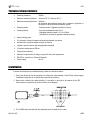
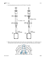
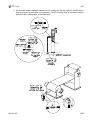
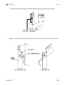
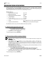
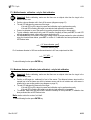
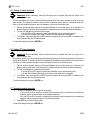
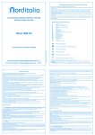
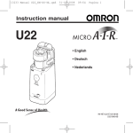
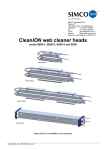
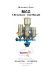
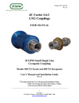
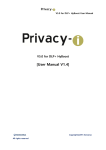
. ENG . US3 Ultrasonic sensor USER’S MANUAL Re S.p.A. US3 Contents Warnings .........................................................................................................................................1 Why to use an ultrasonic sensor...................................................................................................2 Limits of ultrasonic sensors..........................................................................................................2 Applications....................................................................................................................................2 “Pulse-echo” measuring method..................................................................................................3 Factors which influence measurement.........................................................................................3 Technical characteristics...............................................................................................................4 Installation ......................................................................................................................................4 Functioning of the device ..............................................................................................................8 General ....................................................................................................................................................8 Control panel...........................................................................................................................................8 LED bar ...............................................................................................................................................9 Status LED (green)..............................................................................................................................9 “Out of range” LED (red)......................................................................................................................9 Keys.....................................................................................................................................................9 Programming menu......................................................................................................................10 Calibration.....................................................................................................................................11 “Field” calibration by maximum and middle diameter.........................................................................12 “Lab” calibration by maximum diameter and axis...............................................................................13 Configuration of the sensor as distance reader ........................................................................14 Detailed description of the functions..........................................................................................15 F1 - Regulated output type selection (Volt o mA) ..............................................................................15 F2 - Minimum distance calibration (maximum diameter) ...................................................................15 F3 - Middle diameter calibration - only for field calibration................................................................16 F4 - Maximum distance calibration (axis calibration) - only for lab calibration ...................................16 F5 - Setting 1st alarm threshold..........................................................................................................17 F6 - Setting 2nd alarm threshold.........................................................................................................17 F7 - Regulated output inversion.........................................................................................................17 F8 - Led bar mode .............................................................................................................................18 F9 - Thermal probe exclusion ............................................................................................................18 F10 - Exit menu saving the data ........................................................................................................18 Reset .................................................................................................................................................18 Setpoint .........................................................................................................................................19 Electrical and mechanical characteristics..................................................................................20 Mechanical dimensions ...............................................................................................................21 Electrical connection diagrams...................................................................................................22 Guarantee......................................................................................................................................23 I Re S.p.A. US3 Warnings The present manual is for device fitters and operators. It provides indications on the intended use of the device, technical specifications and instructions for installation, adjustment and use. This manual is an integral part of the device and must be kept until the device is decommissioned. It reflects the technical state of the device at the time of its sale. The plant builder may include the present manual in the documentation for plant use. Re S.p.A. reserves the right to update its production and/or manuals without updating products already sold and previous manuals. Since the device forms part of a plant, the plant builder is responsible for ensuring that all parts comply with the laws in force in the country in which it is installed. The device must be fitted and adjusted by qualified technical personnel. It may be moved manually. Information about device recovery The device bears a clear, visible and indelible indication allowing identification of the manufacturer and the separate collection symbol (symbol on side). This symbol, showing a wheelie bin with a cross through it, unequivocally indicates that the device was released after 13.08.2005 and that it must be subject to separate collection. - In European Union member states The device falls within the electrical and electronic equipment category, which must be disposed of not amongst undifferentiated urban waste, but through separate collection. Therefore, at the end of the device’s lifetime, it must be disposed of in conformity with the European standards adopted in the member state in which it was installed. WEEE (Waste Electrical and Electronic Equipment) may be intended for individual, collective or mixed collection and recovery systems at designated centres (for more information contact the relevant local authorities) or may be returned to the distributor when a new item of equipment is purchased. This eliminates or reduces potentially negative effects on the environment deriving from improper use of the equipment or parts of it. For correct waste management, the relevant authorities promote the reduction of final waste disposal by means of re-use, recycling and other forms of recovery to obtain raw materials from waste. In the event of illegal disposal of WEEE, offenders will be punished in accordance with the sanctions established by the member state in which it was installed. - In non-EU countries Recovery and final disposal of the device must be carried out in conformity with the standards in force in the country in which it was installed. It may be advisable to take into account the information provided regarding European Union member states. Rev.02/10/07 1/23 Re S.p.A. US3 Why to use an ultrasonic sensor Ultrasonic sensors are extremely advantageous in comparison with other sensor types: they are able to see every kind of non sound absorbent material and some kind of sound absorbent material; material colour does not interfere with sonar reading; goal object surface does not interfere with sonar reading; ultrasonic sensors work in every environmental conditions (fog, dust, dirty, extremely luminous places or very insufficient lightness); ultrasonic sensors fit to read transparent materials; ultrasonic sensors are able to ignore background disturbs. Limits of ultrasonic sensors They are not suitable for detecting materials particularly good at absorbing sound. They have a relatively low propagation speed, limiting the sensor reading speed. They do not work in water, in high pressure or vacuum environments. They may be affected by the presence of nearby ultrasound sources (e.g.: other ultrasonic sensors or compressed air guns). Applications Laminated materials tension control. Winding and unwinding converting industrial machinery roll diameter measurement (cutter, rotogravure, cutting and winding machines, wrinkling machines). Diameter roll measurement for positioning and working phase starting. Diameter coil measurement (aluminium and sheet). Distance measure. Box inside liquid level measurement. Full and empty box recognition. Rev.02/10/07 2/23 Re S.p.A. US3 “Pulse-echo” measuring method Every 100 milliseconds the US3 sensor emits an ultrasonic pulse at a frequency of 125kHz. The pulse propagates in the air until it hits the target (positioned in front of the sensor) whose distance is to be measured. The pulse is reflected (echo) by the object and picked up by the sensor which, based on the time taken by the echo to return to the sensor and the sound propagation speed, calculates the distance from the object. After the pulse has been generated, the sensor is inhibited for a short time during which it cannot receive the echo. This is a feature common to all “pulse-echo” sensors and defines the minimum distance which can be measured. Factors which influence measurement Although ultrasonic sensors can operate in adverse environmental conditions, it is important to consider several factors which affect measurement quality, so as to achieve the best possible performance: The speed of the sound varies with the temperature, causing a measurement percentage error of around 0.17%/°C. US3 has an internal temperature sensor which allows that error to be compensated for automatically. Big changes in temperature along the measuring path cannot be compensated for and may result in sound diffraction and scattering. Changes in atmospheric pressure do not affect measurements. We strongly advise against the use of ultrasonic sensors in pressurised or vacuum environments, since there may be a significant distortion in the reading. The presence of nebulised liquids or powders in the air attenuates the sound, reducing the maximum reading distance. Draughts may divert the echo and prevent correct measurement. Other ultrasound sources may overlap the echo, causing measurement errors. Moisture may cause a temporary drop in reading sensitivity without damaging the sensor. Do not allow ice to form on the surface of the sensor. Small amounts of dust do not affect measurements. But it is important to keep the sensor clean. Do not paint the surface of the ultrasonic capsule. Clean the sensor with low pressure dry air. Rev.02/10/07 3/23 Re S.p.A. US3 Technical characteristics Operating frequency: 125kHz Minimum measuring distance: 100mm at 25°C (110mm at 50°C ) Maximum measuring distance: 1800mm (for materials which absorb sound: this is reduced in proportion to the degree to which the material absorbs sound) Operating mode: - Diameter reader / Regulator (resolution 0.5mm) 2 analog outputs: - Proportional diametral output 0-10V - Regulated diametral output 0-10V or 4-20mA (possibility of inverting the regulated diametral output) Setpoint analog input 10V reference voltage for setpoint external potentiometer connection Software filter to prevent sudden changes in distance 2 digital outputs for alarms with programmable threshold 10-position multi-purpose LED bar Target present indicator Automatic compensation of change in speed of sound with temperature RS-485 for connection to Personal Computer Power supply: 24V dc Installation To ensure that the device is installed efficiently, follow the instructions below: 1. Even if the device can function properly at a voltage that varies between 18 and 30Vdc, always supply a stabilised voltage that is not affected by network load variations. 2. Never leave a break in the cable shielding. If a connector or joint has to be inserted in the US3 cable, make the connection as shown as shown in the diagram: 3. The CLAMP ferrite provided with the equipment must be applied to the cable. Rev.02/10/07 4/23 Re S.p.A. US3 4. Avoid using single wires connections to the US3 cable, if it is possible. 5. Below is the sensor directivity graph, with an action cone of approximately +/-10°. Install the sensor so that inside said cone there are no: objects other than the target, other ultrasound sources, draughts. Rev.02/10/07 5/23 Re S.p.A. US3 6. Use the metal bracket supplied to support the US3, making sure that the capsule is parallel with the plane at a tangent to the surface to be measured. Connect the sensor body to the nearest machine earth point with a suitable cable, as illustrated below. Rev.02/10/07 6/23 Re S.p.A. US3 7. Be sure that between the sensor body and the machine framework there is electrical continuity 8. Adjust the sensor angle so that the target is at the centre of the action cone. Tighten the knob to secure it. Rev.02/10/07 7/23 Re S.p.A. US3 Functioning of the device General US3 ultrasonic sensor is suitable to read coil diameters: by a simple calibration it is able to convert a distance measure in a coil diameter measure providing a diameter proportional analogue output. It is equipped with an analogue setpoint input which makes US3 a strength self-governing regulation system: you can modify material strength connecting regulated analogue output to a brake and varying the associated tension. Material strength will not change during coil unwinding because brake command tension will be reduced according to diameter. US3 has a second analogue output which varies proportionally to diameter and is not influenced by setpoint input changes, the output can be used to visualize the diameter on a display. Two digital outputs allow the control of relays for activating alarms at diameter values which can be set by the user. A software filter protects the reading against big changes in distance which are not lasting, for example due to coils having an irregular shape. US3 can also function as a distance reader just by using the regulated output inversion. The RS-485 serial port allows rapid sensor configuration using a Personal Computer (with integrated RS485 port or RS-232/RS-485 external converter) and special “US Calibration” software can be downloaded free of charge from the website www.re-spa.com. Control panel LED BAR: for displaying information about the measurement and facilitating navigation in the programming menu LEDs providing useful information about the instrument status KEYS for accessing programming functions Rev.02/10/07 8/23 Re S.p.A. US3 LED bar During programming: shows the number of the function selected, with the corresponding LED lit (the first from the bottom for F1, the second for F2, etc.). Outside programming: indicates the level of the proportional or regulated output depending on the mode set in function F8. Status LED (green) During programming: remains lit Outside programming: flashes. “Out of range” LED (red) During programming: for the meaning of this LED during programming, see the detailed description of the functions. Outside programming: the LED begins flashing quickly if the target moves out of the reading range allowed or cannot be detected by the sensor because it is not there. Keys Outside programming: if pressed for several seconds allows programming to be accessed. ENTER SET During programming: for going to the next function; if pressed with the SET key in function F10, returns you to function F1; if pressed for several seconds in function F10, allows you to exit programming and save the settings; if pressed while field calibration is active, allows output increase/reduction. Outside programming: interrupts LED bar flashing if there was an error saving the settings. During programming: for inverting the value set for functions F1, F7, F8 and F9; for calibrating the parameters in functions F2, F4, F5, F6 and in field calibration; if pressed with the ENTER key in function F10, returns you to function F1. Note: Press ENTER+SET for several seconds outside the programming environment to reset the device, restoring the factory settings. Rev.02/10/07 9/23 Re S.p.A. US3 Programming menu Below is a list summarising the device programming functions available. For more details, see from page 15. To access programming press ENTER for several seconds, the green LED remains lit and the first LED on the LED bar lights up (function F1). To scroll through the menu of the programming functions, use the ENTER key. To return to function F1 go to function F10 and press ENTER+SET. To exit programming go to function F10 and hold down ENTER for several seconds. If the parameters were saved correctly, the LED bar lights scroll, otherwise it begins flashing until you press SET. Function Bar number position Description Keys Value range Factory setting F1 1 Regulated output type selection SET 0→1 0 F2 2 Minimum distance calibration SET 100mm→D.max -1 100mm F3 3 Middle diameter calibration F4 4 Maximum distance calibration SET D.min.+1→1800mm 1800mm F5 5 Setting 1st alarm threshold SET 100mm→1800mm 1600mm F6 6 Setting 2nd alarm threshold SET 100mm→1800mm 1700mm F7 7 Regulated output inversion SET 0→1 0 F8 8 Led bar mode SET 0→1 0 F9 9 Thermal probe exclusion SET 0→1 1 F10 10 Exit menu saving the data ENTER - - Rev.02/10/07 See detailed description of field calibration (page 16) 10/23 Re S.p.A. US3 Calibration To operate as diameter reader / regulator, the US3 ultrasonic sensor must be calibrated. By measuring the distance from the coil, the sensor can measure the coil diameter. In particular, when the coil diameter is at its maximum size the sensor reads the minimum distance. As the diameter is reduced, the distanced measured increases, until the maximum distance corresponding to the minimum diameter (see images below). Rev.02/10/07 11/23 Re S.p.A. US3 “Field” calibration by maximum and middle diameter Where must be done It is a field calibration. Sensor is mechanically installed in its own definitive position. How calibrate Enter the programming menu (see on page 10); Press ENTER to position on function F2; Carry out function F2 for field calibration as described on page 15; Position on function F3 and carry out as described on page 16. Position on function F10 and keep pressed ENTER key to save and exit. Advantages Allows you to set the precise value the output adopts at the intermediate diameter. Disadvantages It is necessary to use a voltmeter. It is necessary to know maximum and middle diameter. Rev.02/10/07 12/23 Re S.p.A. US3 “Lab” calibration by maximum diameter and axis Where must be done The calibration is carried out on lab table before sensor has been mechanically installed in its own position. How calibrate Enter the programming menu (see on page 10); Press ENTER to position on function F2; Carry out function F2 for lab calibration as described on page 15; Position on function F4 and carry out as described on page 16. Position on function F10 and keep pressed ENTER key to save and exit. Advantages It allows to easily calibrate the device in a completely digital way. It is not necessary any measurement instrument. When you order the device if you know the distances between sensor (capsule surface) and maximum diameter coil and between regulator and rotation axis, US3 could be sold already calibrated for the specific application. Disadvantages You must pay attention to position the stiff target (ex. cardboard) as more parallel as possible to the capsule plane. It is necessary to know the distances between sensor (capsule plane) and maximum diameter and between regulator and rotation axis. Attention: the procedure described above could be carried out when sensor has been already mechanically installed in its own definitive position, using two targets, one corresponding to maximum diameter (F2) the other one to rotation axis (F4). Rev.02/10/07 13/23 Re S.p.A. US3 Configuration of the sensor as distance reader To use the sensor as distance reader you have to: enter the programming menu (see on page 10); press ENTER to position on function F7; the red LED shows the current value of the function: - if the red LED is lit the inversion is already enabled, - if the red LED is off the inversion is disabled: press SET key to enable the inversion; position on function F10 and keep pressed ENTER key to save and exit. short-circuit the green and brown wires (as shown in the diagram on page 22, Configuration without setpoint potentiometer section) In this way the 0V regulated output corresponds to the minimum distance, instead the 10V regulated output corresponds to the maximum distance. Rev.02/10/07 14/23 Re S.p.A. US3 Detailed description of the functions Outside programming, the green LED flashes to indicate that the device is operating normally. To access the programming menu, hold down ENTER for several seconds. The green LED will stop flashing and remain lit together with the LED on the LED bar corresponding to function F1. Nominal values are: Regulated diametrical output: Distance from the axis: Distance from the maximum diameter: 1st alarm distance: 2nd alarm distance: Inversion of the regulated diametrical output: Led bar: Instrument serial identification: set on Volt 1,8 meters 10 cm 1,6 meters 1,7 meters disabled set to display the level of the proportional diametrical output 0 (changeable only using Personal Computer). See Calibration section to carry out the first calibration after sensor purchase. F1 - Regulated output type selection (Volt o mA) The red LED shows the current value of the function: - if the red LED is lit the type of output is mA - if the red LED is off the type of output is Volts Press SET key to set the desired value. To select following function press ENTER key. F2 - Minimum distance calibration (maximum diameter) Important: Before calibrating, make sure that there are no objects other than the target in the sensor’s action cone. Lab calibration (sensor not installed in its own working position): position a stiff target (ex. cardboard) in front of the sensor. The distance between target and the capsule has to be the same one which is between sensor and maximum diameter coil once sensor is installed in its own working position (see diagram on page 13). Field calibration (sensor installed in its own working place): position maximum diameter coil in front of the sensor (see diagram on page 12). The red LED indicates the presence of the target: - if the red LED is off the target is present and calibration can be performed correctly - if the red LED is flashing the target is not detected and calibration is impossible To calibrate, make sure that the red LED remains constantly off then press SET; if calibration has been performed the red LED flashes twice. To select following function press ENTER key. Rev.02/10/07 15/23 Re S.p.A. US3 F3 - Middle diameter calibration - only for field calibration Important: Before calibrating, make sure that there are no objects other than the target in the sensor’s action cone. Position a known diameter coil in front off the sensor (diagram on page 12). The red LED indicates the presence of the target: - if the red LED is off the target is present and calibration can be performed correctly - if the red LED is flashing the target is not detected and calibration is impossible Connect a voltmeter to one of the sensor’s two analog outputs (blue wire or orange wire). To start calibration make sure that the red LED remains constantly off then press SET; the red LED will light up and the output voltage will increase starting from 5V. Use the ENTER key to increase or reduce the voltage. When the output reaches the value calculated using the formula shown below, press SET to confirm it. If calibration has been performed the red LED flashes twice. volt = (10 * known diameter [mm]) maximum diameter [mm] Es. If maximum diameter is 1000 mm and known diameter is 400 mm, output must be 4Vdc. volt = (10 * 400) = 4 1000 To select following function press ENTER key. F4 - Maximum distance calibration (axis calibration) - only for lab calibration Important: Before calibrating, make sure that there are no objects other than the target in the sensor’s action cone. Position a stiff target (ex. cardboard) in front of the sensor. The distance between target and the capsule has to be the same one which is between sensor and the coil rotation axis once sensor is installed in its own working position (see diagram on page 13). The red LED indicates the presence of the target: - if the red LED is off the target is present and calibration can be performed correctly - if the red LED is flashing the target is not detected and calibration is impossible To calibrate, make sure that the red LED remains constantly off then press SET; if calibration has been performed the red LED flashes twice. Note: rotation axis is the centre of coil shaft. To select following function press ENTER key. Rev.02/10/07 16/23 Re S.p.A. US3 F5 - Setting 1st alarm threshold Important: Before calibrating, make sure that there are no objects other than the target in the sensor’s action cone. This function allows you to set a threshold diameter below which the sensor activates the first of the two alarm outputs. The output will remain activated until the diameter returns above the threshold value plus 5mm, to prevent sudden activations when the diameter is close to the threshold value. Place a coil with diameter equal to the threshold diameter in front of the sensor (or an obstacle at a distance equal to that which would separate the capsule from the coil with the threshold diameter). The red LED indicates the presence of the target: - if the red LED is off the target is present and calibration can be performed correctly - if the red LED is flashing the target is not detected and calibration is impossible To calibrate, make sure that the red LED remains constantly off then press SET; if calibration has been performed the red LED flashes twice. To select following function press ENTER key. F6 - Setting 2nd alarm threshold Important: Before calibrating, make sure that there are no objects other than the target in the sensor’s action cone. This function allows you to set a second threshold diameter below which the sensor activates the second of the two alarm outputs. The output will remain activated until the diameter returns above the threshold value plus 5mm, to prevent sudden activations when the diameter is close to the threshold value. Place a coil with diameter equal to the threshold diameter in front of the sensor (or an obstacle at a distance equal to that which would separate the capsule from the coil with the threshold diameter). The red LED indicates the presence of the target: - if the red LED is off the target is present and calibration can be performed correctly - if the red LED is flashing the target is not detected and calibration is impossible To calibrate, make sure that the red LED remains constantly off then press SET; if calibration has been performed the red LED flashes twice. To select following function press ENTER key. F7 - Regulated output inversion The red LED shows the current value of the function: - if the red LED is lit the inversion is enabled (the maximum output corresponds to the minimum diameter and the minimum output to the maximum diameter) - if the red LED is off the inversion is disabled (the maximum output corresponds to the maximum diameter and the minimum output to the minimum diameter) Press SET key to set the desired value. To select following function press ENTER key. Rev.02/10/07 17/23 Re S.p.A. US3 F8 - Led bar mode The red LED shows the current value of the function: - if the red LED is lit the LED bar shows the level of the regulated output - if the red LED is off the LED bar shows the level of the proportional output Press SET key to set the desired value. To select following function press ENTER key. F9 - Thermal probe exclusion The red LED shows the current value of the function: - if the red LED is lit the temperature compensation is disabled (the probe is excluded) - if the red LED is off the temperature compensation in enabled (the probe is active) Press SET key to set the desired value. To select following function press ENTER key. It is recommended to exclude the probe when the ambient temperature is between 15° and 25°C or in case of probe malfunctioning. F10 - Exit menu saving the data To return to function F1 press ENTER and SET simultaneously. To exit the programming menu and save the changes, hold down ENTER for several seconds. If there are no errors the LED bar lights scroll and the green LED starts flashing again. If errors are found the LED bar keeps flashing and the changes are not saved. Press SET to stop the flashing, go back into the programming menu and repeat the calibration. If the error persists, contact the technical support team. Reset To reset the sensor hold down ENTER and SET for several seconds while the sensor is outside the programming menu. The LED bar lights will scroll and the function values are returned to the factory settings. If the LED bar keeps flashing after a reset, contact the technical support team. Attention: If during ultrasonic sensor functioning something goes wrong reset functions and calibrate the instrument again. Whenever problems do not disappear please get in touch with our technical assistance office. Rev.02/10/07 18/23 Re S.p.A. US3 Setpoint The input allows to vary US3 sensor output according to your own requirements. Input signal value must be between 0V and 10V. It is also possible to connect an external potentiometer, as indicated in Electrical connection diagram section. Varying setpoint signal, output value will depend on target distance and on input signal, as shown in the following graph. Output value [mA] o [V] 100 % tpo se = in t V 10 50 % oint setp 0 =5 V max Coil diameter If you decide to reverse regulated output (F7 function) setpoint variation will intervene on output itself as shown in the graph below: Output value [mA] o [V] 100 % se tpo int 50 % setp oint = 0 Rev.02/10/07 =1 0V 5V max Coil diameter 19/23 Re S.p.A. US3 Electrical and mechanical characteristics Power supply: 24V dc (18-30V dc including ripple) protection against polarity reversal Mean power: about 2W, at 24Vdc Analog input: 0÷10Vdc for working curve Regulated analog output: 0÷10Vdc (RL>1kΩ) 4÷20mA (RL<300Ω) Proportional analog output: 0÷10Vdc (RL>1kΩ) Alarm outputs: Open Collector 100mA MAX 30Vdc MAX Serial port: RS485 Transmission speed: 9.6kbaud Output updating time: 125 msec Sensor type: piezoelectric transducer Ultrasound frequency: 125kHz Opening angle: +/-10° to the axis Working temperature: 0÷50°C (referred to the sensor ambient) Box material: Aluminium ENAW 6082 Weight: 280 g Cable (5 or 10 m): 10 poles with miniaturized connector Rev.02/10/07 20/23 Re S.p.A. US3 Mechanical dimensions Rev.02/10/07 21/23 Re S.p.A. US3 Electrical connection diagrams Configuration with setpoint potentiometer (see on page 19) +VDC Vref PROP. OUT REG. OUT RED BROWN ORANGE BLUE SETPOINT IN RS485 + (A) RS485 - (B) GREEN ALARM 1 OUT WHITE ALARM 2 OUT YELLOW 0V Setpoint potentiometer VIOLET GREY Coil relè Coil relè Vrelè Vrelè BLACK Configuration without setpoint potentiometer: In this case it’s necessary to link up the green cable to the brown one; if you do not link the cables the regulated analog output (blue wire) is constant and 0Volt (or 4mA). +VDC Vref PROP. OUT REG. OUT BLUE GREEN ALARM 1 OUT WHITE 0V Rev.02/10/07 BROWN ORANGE SETPOINT IN RS485 + (A) RS485 - (B) ALARM 2 OUT Wire colour Red Black White Yellow Orange Blue Green Brown Grey Violet RED Pin 1 8 9 10 4 3 6 5 7 2 VIOLET GREY YELLOW Coil relè Coil relè Vrelè Vrelè BLACK Function Supply 18÷30Vdc 0V Alarm output 1 Alarm output 2 Proportional analog output Regulated analog output Setpoint input 0÷10V Setpoint reference +10Vdc RS485 serial output - (B) RS485 serial output + (A) 22/23 Re S.p.A. US3 Guarantee Re S.p.A. guarantees this device against all defects relative to the materials and manufacturing for a period of 12 months from the date of delivery. Should your device develop operating faults during the guarantee period, please contact the Company’s agent in your country, or, if this is not possible, contact Re S.p.A. directly. The guarantee includes spare parts and labour. It does not include shipment costs for device delivery or recall. The guarantee is invalidated by: improper use of the device incorrect installation faulty electrical connections or power supply lack of maintenance changes or work involving non-original components or carried out by persons without Re S.p.A authorisation complete or partial failure to observe the instructions exceptional events. At the end of the guarantee period, support will be provided by the support network, which will carry out repairs at the current rates. Rev.02/10/07 23/23 Re S.p.A. Controlli Industriali Via Firenze, 3 – 20060 BUSSERO (MI) ITALY Fax (+39) 02 95 03 89 86 Technical support: Tel. (+39) 02 95 24 30.300 - E-mail: [email protected] Sales support: Tel. (+39) 02 95 24 30.200 - E-mail: [email protected] www.re-spa.com Rev. 10/07