1
8LS Three-phase Synchronous Motors User´s Manual
8LS Three-phase Synchronous Motors
User´s Manual
MAMOT2-ENG
Version 1.1
MAMOT2-ENG
8LS Three-phase
Synchronous Motors
User's Manual
Version:
Model No.:
1.1 (November 2005)
MAMOT2-ENG
We reserve the right to change the contents of this manual without warning. The information
contained herein is believed to be accurate as of the date of publication; however, Bernecker +
Rainer Industrie-Elektronik Ges.m.b.H. makes no warranty, expressed or implied, with regards
to the products or the documentation contained within this book. In addition, Bernecker + Rainer
Industrie-Elektronik Ges.m.b.H. shall not be liable in the event of incidental or consequential
damages in connection with or resulting from the furnishing, performance, or use of these
products. The software names, hardware names, and trademarks used in this document are
registered by the respective companies.
8LS Three-phase Synchronous Motors User's Manual V 1.1
1
2
8LS Three-phase Synchronous Motors User's Manual V 1.1
Chapter 1: General Information
Chapter 2: Technical Data
Chapter 3: Installation
Chapter 4: Wiring
Chapter 5: Standards and Certifications
Figure Index
8LS Three-phase Synchronous Motors User's Manual V 1.1
3
4
8LS Three-phase Synchronous Motors User's Manual V 1.1
Table Index
Index
Model Number Index
8LS Three-phase Synchronous Motors User's Manual V 1.1
5
6
8LS Three-phase Synchronous Motors User's Manual V 1.1
Table of Contents
Table of Contents
Chapter 1: General Information ..................................................... 11
1. 8LS Three-phase Synchronous Motors ..............................................................................
1.1 Feedback Systems Specified to Meet your Needs ........................................................
1.2 Embedded Parameter Chip ...........................................................................................
1.3 Smooth Surface .............................................................................................................
1.4 Connection Technology .................................................................................................
1.5 Custom Configurations ..................................................................................................
2. Safety Guidelines ................................................................................................................
2.1 General Information .......................................................................................................
2.2 Intended Use .................................................................................................................
2.3 Transport and Storage ..................................................................................................
2.4 Installation .....................................................................................................................
2.5 Operation .......................................................................................................................
2.5.1 Protection against Touching Electrical Parts ..........................................................
2.5.2 Protection from Dangerous Movements .................................................................
2.5.3 Protection from Burns .............................................................................................
2.6 Organization of Safety Notices ......................................................................................
11
12
13
13
14
14
15
15
16
16
16
17
17
18
19
19
Chapter 2: Technical Data .............................................................. 21
1. 8LS Three-phase Synchronous Motors ..............................................................................
1.1 General Description .......................................................................................................
1.1.1 Cooling Types .........................................................................................................
1.1.2 Sizes .......................................................................................................................
1.1.3 Lengths ...................................................................................................................
1.2 Motor Encoder Systems ................................................................................................
1.2.1 EnDat Encoder ........................................................................................................
1.2.2 Resolver ..................................................................................................................
1.3 Motor Options ................................................................................................................
1.3.1 Rated Speed ...........................................................................................................
1.3.2 Oil Seal ...................................................................................................................
1.3.3 Holding Brake .........................................................................................................
1.3.4 Type of Shaft End ...................................................................................................
1.3.5 Load Capacity of the Shaft End and Bearing ..........................................................
1.3.6 Connection Direction ...............................................................................................
1.3.7 Determining the Order Code for Motor Options (ff) .................................................
1.4 Special Motor Options ...................................................................................................
1.4.1 "Reinforced A side bearing" ....................................................................................
1.5 Order Key ......................................................................................................................
1.5.1 Example Order 1 .....................................................................................................
1.5.2 Example Order 2 .....................................................................................................
1.6 General Motor Data .......................................................................................................
1.7 Terminology and Formula Symbols ...............................................................................
1.7.1 Connection Direction, Bearing ................................................................................
1.7.2 Definitions for Maximum Shaft Load Diagrams .......................................................
1.7.3 Formula Symbols ....................................................................................................
1.8 Motor Data Overview Cooling Type A ...........................................................................
8LS Three-phase Synchronous Motors User's Manual V 1.1
21
21
22
22
22
23
23
24
25
25
26
26
27
28
31
32
33
33
34
35
35
36
38
38
38
39
41
7
Table of Contents
1.9 Motor Data 8LSA2 .........................................................................................................
1.9.1 Technical Data ........................................................................................................
1.9.2 Speed-Torque Characteristic Curves with 400 VAC Supply Voltage ......................
1.9.3 Speed-Torque Characteristic Curves with 230 VAC Supply Voltage ......................
1.9.4 Dimensions .............................................................................................................
1.9.5 Maximum Shaft Load ..............................................................................................
1.10 Motor Data 8LSA3 .......................................................................................................
1.10.1 Technical Data ......................................................................................................
1.10.2 Speed-Torque Characteristic Curves with 400 VAC Supply Voltage ....................
1.10.3 Speed-Torque Characteristic Curves with 230 VAC Supply Voltage ....................
1.10.4 Dimensions ...........................................................................................................
1.10.5 Maximum Shaft Load ............................................................................................
1.11 Motor Data 8LSA4 .......................................................................................................
1.11.1 Technical Data ......................................................................................................
1.11.2 Speed-Torque Characteristic Curves with 400 VAC Supply Voltage ....................
1.11.3 Speed-Torque Characteristic Curves with 230 VAC Supply Voltage ....................
1.11.4 Dimensions ...........................................................................................................
1.11.5 Maximum Shaft Load ............................................................................................
1.12 Motor Data 8LSA5 .......................................................................................................
1.12.1 Technical Data ......................................................................................................
1.12.2 Speed-Torque Characteristic Curves with 400 VAC Supply Voltage ....................
1.12.3 Speed-Torque Characteristic Curves with 230 VAC Supply Voltage ....................
1.12.4 Dimensions ...........................................................................................................
1.12.5 Maximum Shaft Load ............................................................................................
1.13 Motor Data 8LSA6 .......................................................................................................
1.13.1 Technical Data ......................................................................................................
1.13.2 Speed-Torque Characteristic Curves with 400 VAC Supply Voltage ....................
1.13.3 Speed-Torque Characteristic Curves with 230 VAC Supply Voltage ....................
1.13.4 Dimensions ...........................................................................................................
1.13.5 Maximum Shaft Load ............................................................................................
1.14 Motor Data 8LSA7 .......................................................................................................
1.14.1 Technical Data ......................................................................................................
1.14.2 Speed-Torque Characteristic Curves with 400 VAC Supply Voltage ....................
1.14.3 Speed-Torque Characteristic Curves with 230 VAC Supply Voltage ....................
1.14.4 Dimensions ...........................................................................................................
1.14.5 Maximum Shaft Load ............................................................................................
1.15 Motor Data 8LSA8 .......................................................................................................
1.15.1 Technical Data ......................................................................................................
1.15.2 Speed-Torque Characteristic Curves with 400 VAC Supply Voltage ....................
1.15.3 Speed-Torque Characteristic Curves with 230 VAC Supply Voltage ....................
1.15.4 Dimensions ...........................................................................................................
1.15.5 Maximum Shaft Load ............................................................................................
2. Cables .................................................................................................................................
2.1 General Information .......................................................................................................
2.1.1 Prefabricated Cable ................................................................................................
2.2 Motor Cables .................................................................................................................
2.2.1 Order Data ..............................................................................................................
8
47
47
48
50
52
53
54
54
55
57
59
60
61
61
62
64
66
67
68
68
69
71
74
75
76
76
77
79
81
82
83
83
84
85
87
88
89
89
90
92
94
95
96
96
96
97
97
8LS Three-phase Synchronous Motors User's Manual V 1.1
Table of Contents
2.2.2 Technical Data ........................................................................................................ 99
2.3 EnDat Cables .............................................................................................................. 101
2.3.1 Order Data ............................................................................................................ 101
2.3.2 Technical Data ...................................................................................................... 101
2.4 Resolver Cables .......................................................................................................... 103
2.4.1 Order Data ............................................................................................................ 103
2.4.2 Technical Data ...................................................................................................... 103
3. Connectors ....................................................................................................................... 105
3.1 General Information ..................................................................................................... 105
3.2 Motor Connectors ........................................................................................................ 106
3.2.1 Order Data ............................................................................................................ 106
3.2.2 Technical Data for 8PM001.00-1 and 8PM002.00-1 ............................................. 107
3.2.3 Technical Data for 8PM003.00-1 .......................................................................... 108
3.3 Encoder Connectors .................................................................................................... 109
3.3.1 Order Data ............................................................................................................ 109
3.3.2 Technical Data for EnDat Connector 8PE001.00-1 .............................................. 110
3.3.3 Technical Data for Resolver Connector 8PR001.00-1 .......................................... 111
Chapter 3: Installation .................................................................. 113
1. General Information ..........................................................................................................
1.1 Mounting Drive Elements ............................................................................................
1.2 Connection Plugs ........................................................................................................
2. Detailed Dimensions .........................................................................................................
2.1 Detailed Dimensions for "Top" Connection Direction ..................................................
2.1.1 Motor Connector ...................................................................................................
2.1.2 Encoder Connection .............................................................................................
2.2 Detailed Dimensions for "Swiveling" Connection Direction .........................................
2.2.1 Motor Connector ...................................................................................................
2.2.2 Encoder Connection .............................................................................................
2.3 Outer Dimensions of the Connectors ..........................................................................
113
113
114
115
115
115
115
116
116
117
117
Chapter 4: Wiring .......................................................................... 119
1. 8LS Connection Assignments ...........................................................................................
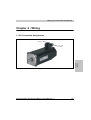
1.1 Motor Cable Connection ..............................................................................................
1.1.1 8LSA2...8LSA7 .....................................................................................................
1.1.2 8LSA8 ...................................................................................................................
1.2 Encoder Cable Connection .........................................................................................
1.2.1 EnDat ....................................................................................................................
1.2.2 Resolver ................................................................................................................
2. Cables ...............................................................................................................................
2.1 Motor Cables ...............................................................................................................
2.1.1 Motor Cable Construction .....................................................................................
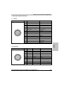
2.1.2 Pin Assignments for 8CMxxx.12-1, 8CMxxx.12-3 .................................................
2.1.3 Cable Schematic for 8CMxxx.12-1, 8CMxxx.12-3 ................................................
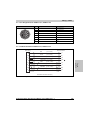
2.1.4 Pin Assignments for 8CMxxx.12-5 ........................................................................
2.1.5 Cable Schematic for 8CMxxx.12-5 .......................................................................
8LS Three-phase Synchronous Motors User's Manual V 1.1
119
120
120
120
121
121
121
122
122
122
123
123
124
124
9
Table of Contents
2.2 EnDat Encoder Cables ................................................................................................
2.2.1 EnDat Encoder Cable Construction ......................................................................
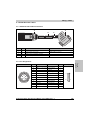
2.2.2 Pin Assignments ...................................................................................................
2.2.3 Cable Schematic ...................................................................................................
2.3 Resolver Cables ..........................................................................................................
2.3.1 Resolver Cable Construction ................................................................................
2.3.2 Pin Assignments ...................................................................................................
2.3.3 Cable Schematic ...................................................................................................
125
125
125
126
127
127
127
128
Chapter 5: Standards and Certifications .................................... 129
1. Valid European Guidelines ...............................................................................................
2. Valid Standards for Servo Motors .....................................................................................
3. International Certifications ................................................................................................
4. Standards, Definitions for Safety Techniques ...................................................................
10
129
129
130
131
8LS Three-phase Synchronous Motors User's Manual V 1.1
Chapter 1
General Information
General Information • 8LS Three-phase Synchronous Motors
Chapter 1 • General Information
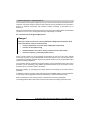
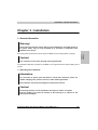
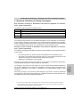
1. 8LS Three-phase Synchronous Motors
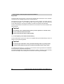
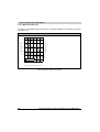
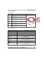
B&R 8LS three-phase synchronous motors have been specially developed for use in highperformance applications. They are now being used to produce consumer goods and products
in the plastic, packaging, metal, food and beverage industries and then palletize them with
material handling systems.
Complete solutions from one source, this requires the right components as well as the right
configuration for the application environment. The large selection of available 8LS three-phase
synchronous motors makes it possible to easily meet conditions such as reducing the variety of
parts, guaranteeing ease of service and maintaining minimum requirements on space.
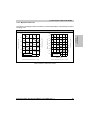
Figure 1: 8LS Three-phase synchronous motors
8LS Three-phase Synchronous Motors User's Manual V 1.1
11
General Information • 8LS Three-phase Synchronous Motors
An optimally configured drive rounds off a successful design. To meet this goal, specialists are
available in B&R subsidiaries all over the world who are eager to share their know-how in the
area of mechatronics.
B&R automation components, the economical combination of mechanics, electronics,
technology and innovation.
1.1 Feedback Systems Specified to Meet your Needs
The 8LS three-phase synchronous motors are available with different encoder systems. As
standard, they are equipped with Heidenhain EnDat encoders. Depending on the application, the
customer can select between normal and high-resolution encoders. Both types are also
available as multi-turn encoders. They allow operation without requiring homing procedures or
additional measurement systems on the work piece. The absolute encoder functions without a
battery and is therefore absolutely maintenance free.
The 8LS three-phase synchronous motors are also available with resolvers for machines with
lower precision and speed requirements.
12
8LS Three-phase Synchronous Motors User's Manual V 1.1
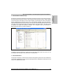
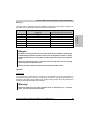
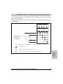
1.2 Embedded Parameter Chip
All relevant mechanical and electrical information and data is stored in the encoder used for the
8LS three-phase synchronous motors. This means that the user doesn't have to make settings
on the servo drive in the field. As soon as the encoder is connected to the servo drive and the
power is applied to the electronics, the motor is automatically identified. The motor sends the
rated and limit parameters to the servo drive. Then the drive automatically determines the current
limits and current control parameters required for optimal control of the motor. The user only has
to optimize the speed and position controller. The integrated start-up environment in
B&R Automation Studio™ provides assistance.
Figure 2: Start-up with B&R Automation Studio™
In addition to start-up assistance, routine service work is also made easier and motors can be
exchanged without having to take extra time to set parameters.
1.3 Smooth Surface
The special construction of the surface of the 8LS three-phase synchronous motors allow them
to be used in applications for the food and beverage branch. Depressions where liquid could
collect were deliberately avoided.
8LS Three-phase Synchronous Motors User's Manual V 1.1
13
Chapter 1
General Information
General Information • 8LS Three-phase Synchronous Motors
General Information • 8LS Three-phase Synchronous Motors
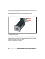
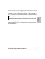
1.4 Connection Technology
The uniform connection technology, the prefabricated cables and the embedded parameter chip
described above allow plug and play operation of the power transmission system.
The angled connectors can be swiveled, which provides the maximum amount of flexibility during
cabling.
Figure 3: Swivel connectors
1.5 Custom Configurations
B&R has already developed successful projects where a custom drive configuration was
required. An example is direct attachment of a pulley to the motor shaft. Using bearings that
withstand the high radial forces required by the construction allows the motor and belt drive to
be easily installed. High-alloy steel is used to keep the shaft diameter small for trouble free
mounting of small belt disks (in spite of heavy loads).
Advantages of B&R drives for your application:
14
•
Easy to install
•
Small installation dimensions
•
Extremely easy to service
•
Lower costs
8LS Three-phase Synchronous Motors User's Manual V 1.1
2. Safety Guidelines
Information:
The following safety guidelines are valid for servo motors and servo drives with
regard to uniform handling independent of the manual where they are listed.
2.1 General Information
B&R servo drives and servo motors have been designed, developed and manufactured for
conventional use in industry. They were not designed, developed and manufactured for any use
involving serious risks or hazards that could lead to death, injury, serious physical damage, or
loss of any kind without the implementation of exceptionally stringent safety precautions.
Such risks include in particular the use of these devices to monitor nuclear reactions in nuclear
power plants, as well as flight control systems, flight safety, the control of mass transportation
systems, medical life support systems, and the control of weapons systems.
Danger!
Servo drives and servo motors can have bare parts with voltages applied (e.g.
terminals) or hot surfaces. Additional sources of danger result from moving
machine parts. Improperly removing the required covers, inappropriate use,
incorrect installation or incorrect operation can result in severe personal injury or
damage to property.
All tasks, such as transport, installation, commissioning and service, are only permitted to be
carried out by qualified personnel. Qualified personnel are persons familiar with transport,
mounting, installation, commissioning and operation of the product and have the respective
qualifications (e.g. IEC 60364). National accident prevention guidelines must be followed.
The safety guidelines, connection descriptions (type plate and documentation), and limit values
listed in the technical data are to be read carefully before installation and commissioning and
must be observed.
Danger!
Handling servo drives and servo motors incorrectly can cause severe personal
injury or damage to property!
8LS Three-phase Synchronous Motors User's Manual V 1.1
15
Chapter 1
General Information
General Information • Safety Guidelines
General Information • Safety Guidelines
2.2 Intended Use
Servo drives are components designed to be installed in electrical systems or machines. They
are not being used as intended unless the machine meets EG regulation 98/37/EG (machine
regulation) as well as regulation 89/336/EWG (EMC regulation).
Servo drives are only permitted to be operated directly on grounded, three-phase industrial
mains (TN, TT power mains). When using them in living areas, shops and small businesses,
additional filtering measures must be implemented by the user.
Danger!
Servo drives are not permitted to be operated directly on IT and TN-S mains with a
grounded phase conductor and protective ground conductor!
The technical data as well as the values for connection and environmental specifications can be
found on the type plate and in the user's manual. The connection and environmental
specifications must be met!
Danger!
Electronic devices are generally not failsafe. If the servo drive fails, the user is
responsible for making sure that the motor is placed in a secure state.
2.3 Transport and Storage
During transport and storage, devices must be protected from excessive stress (mechanical
load, temperature, humidity, aggressive atmosphere, etc.).
Servo drives contain components sensitive to electrostatic charges which can be damaged by
inappropriate handling. It is therefore necessary to provide the required safety precautions
against electrostatic discharges during installation or removal of servo drives.
2.4 Installation
The installation must take place according to the user's manual using suitable equipment and
tools.
Devices may only be installed without voltage applied and by qualified personnel. Before
installation, voltage to the switching cabinet should be switched off and prevented from being
switched on again.
The general safety regulations and national accident prevention guidelines (e.g. VBG 4) must be
observed when working with high voltage systems.
Electrical installation must be carried out according to the relevant guidelines (e.g. line cross
section, fuse, protective ground connection).
16
8LS Three-phase Synchronous Motors User's Manual V 1.1
General Information • Safety Guidelines
Chapter 1
General Information
2.5 Operation
2.5.1 Protection against Touching Electrical Parts
Danger!
To operate servo drives, it is necessary that certain parts are carrying voltages over
42 VDC. A life-threatening electrical shock could occur if you come into contact with
these parts. This could result in death, severe injury, or material damage.
Before turning on a servo drive, make sure that the housing is properly connected to ground
(PE rail). The ground connection must be made, even when testing the servo drive or when
operating it for a short time!
Before turning the device on, make sure that all voltage-carrying parts are securely covered.
During operation, all covers and switching cabinet doors must remain closed.
Control and high power contacts can have voltage applied, even when the motor is not turning.
Touching the contacts when the device is switched on is not permitted.
Before working on servo drives, they must be disconnected from the power mains and prevented
from being switched on again.
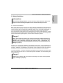
Danger!
After switching off the servo drive, wait until the DC bus discharge time of at least
five minutes has passed. The voltage currently on the DC bus must be measured
between -DC1 and +DC1 with a suitable measuring device before beginning work.
This voltage must be less than 42 V DC to rule out danger. The Run LED going out
does not indicate that voltage is not present on the device!
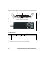
The servo drives are labeled with the following warning:
Figure 4: Warning on the servo drives
8LS Three-phase Synchronous Motors User's Manual V 1.1
17
General Information • Safety Guidelines
The connections for the signal voltages (5 to 30 V) found on the servo drives are isolated circuits.
Therefore, the signal voltage connections and interfaces are only permitted to be connected to
devices or electrical components with sufficient isolation according to IEC 60364-4-41 or
EN 50178.
Never remove the electrical connections from the servo drive with voltage applied. In unfavorable
conditions, arcs can occur causing personal injury and damage to contacts.
2.5.2 Protection from Dangerous Movements
Danger!
Incorrect control of motors can cause unwanted and dangerous movements! Such
incorrect behavior can have various causes:
•
Incorrect installation or an error when handling the components
•
Incorrect or incomplete wiring
•
Defective devices (servo drive, motor, position encoder, cable, brake)
•
Incorrect control (e.g. caused by software error)
Some of these causes can be recognized and prevented by the servo drive using internal
monitoring. However, it is generally possible for the motor shaft to move every time the device
is switched on! Therefore protection of personnel and the machine can only be guaranteed using
higher level safety precautions.
The movement area of machines must be protected to prevent accidental access. This type of
protection can be obtained by using stabile mechanical protection such as protective covers,
protective fences, protective gates or photocells.
Removing, bridging or bypassing these safety features and entering the movement area is
prohibited.
A sufficient number of emergency stop switches are to be installed directly next to the machine.
The emergency stop equipment must be checked before commissioning the machine.
Remove shaft keys on free running motors or prevent them from being catapulted.
The holding brake built into the motors cannot prevent hoists from allowing the load to sink.
18
8LS Three-phase Synchronous Motors User's Manual V 1.1
General Information • Safety Guidelines
Chapter 1
General Information
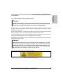
2.5.3 Protection from Burns
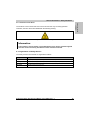
The surfaces of servo drives and servo motors can become very hot during operation.
Therefore, the servo drives are labeled with the following warning:
Figure 5: "Hot surface" warning
Information:
A "hot surface" warning sticker is provided with the servo motors. It must be applied
so that it can be seen at any time after the motor has been mounted.
2.6 Organization of Safety Notices
The safety notices in this manual are organized as follows:
Safety notice
Description
Danger!
Disregarding the safety regulations and guidelines can be life-threatening.
Warning!
Disregarding the safety regulations and guidelines can result in severe injury or major damage to material.
Caution!
Disregarding the safety regulations and guidelines can result in injury or damage to material.
Information:
Important information for preventing errors.
Table 1: Description of the safety notices used in this manual
8LS Three-phase Synchronous Motors User's Manual V 1.1
19
General Information • Safety Guidelines
20
8LS Three-phase Synchronous Motors User's Manual V 1.1
Technical Data • 8LS Three-phase Synchronous Motors
Chapter 2 • Technical Data
1.1 General Description
The three-phase synchronous motors from the 8LS series are permanently excited,
electronically commutated synchronous motors for applications that require excellent dynamic
characteristics and positioning precision as well as compact size and reduced weight.
•
NdFeB permanent magnets
•
Sinusoidal commutation with EnDat encoder or resolver as feedback unit
•
Three-phase winding with star connection
•
Compact sizes result in low weight
•
Minimum moment of inertia because of favorable rotor construction results in very good
dynamic properties
•
High overload capability/peak torque
•
Low torque ripple
•
High dynamic torque at high speeds
•
Long life-span, all motor parts except for bearings are free of wear
•
Direct diversion of lost power generated in the stator over the housing to the flange
•
Preloaded, grooved ball bearings which are sealed on both sides and greased
•
Complete motor system with stall torque ranging from 0.2 Nm to 115 Nm
•
Connection using two circular plugs
•
Controlled by ACOPOS servo drives
Warning!
8LS three-phase synchronous motors are not permitted to be connected directly to
the power mains, they are only permitted to be operated in combination with
ACOPOS servo drives!
8LS Three-phase Synchronous Motors User's Manual V 1.1
21
Chapter 2
Technical Data
1. 8LS Three-phase Synchronous Motors
Technical Data • 8LS Three-phase Synchronous Motors
Warning!
High temperatures can occur on the surface of the 8LS three-phase synchronous
motors (> 100 °C). If necessary, protection against accidental contact should be
installed!
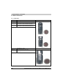
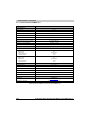
1.1.1 Cooling Types
Cooling Type A
8LS three-phase synchronous motors with cooling type A are self-cooling and have a long, slim
design. The motors must be installed on the cooling surface (= flange).
Caution!
Free convection on the motor housing must be guaranteed!
1.1.2 Sizes
The 8LS three-phase synchronous motors are available in seven different sizes (2 to 8). They
are different regarding dimensions (especially flange dimensions) and power rating.
The various sizes can be differentiated by a number (c) in the model number. The larger the
number, the larger the flange dimensions and power rating for the respective motor.
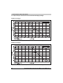
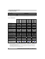
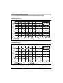
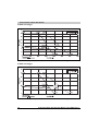
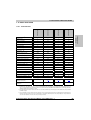
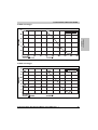
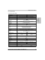
1.1.3 Lengths
The 8LS three-phase synchronous motors are available in up to five different lengths. They have
different power ratings with identical flange dimensions.
The various lengths can be differentiated by a number (d) in the model number.
Overview
Length
Code
Available for Size
Description
2
3
4
5
6
7
8
3
Small rated torque
Yes
Yes
Yes
Yes
Yes
Yes
Yes
4
Medium rated torque
Yes
Yes
Yes
Yes
Yes
Yes
Yes
5
Large rated torque
Yes
Yes
Yes
Yes
Yes
Yes
Yes
6
Extra large rated torque
Yes
Yes
Yes
Yes
Yes
---
Yes
7
Exceptionally large rated torque
---
---
---
Yes
---
---
---
Table 2: Available lengths
22
8LS Three-phase Synchronous Motors User's Manual V 1.1
Technical Data • 8LS Three-phase Synchronous Motors
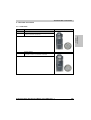
1.2 Motor Encoder Systems
The 8LS three-phase synchronous motors are available with EnDat encoders and also with
resolvers. The encoder system is listed as part of the model number in the form of a 2-digit code
(ee).
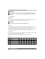
1.2.1 EnDat Encoder
EnDat is a standard developed by Johannes Heidenhain GmbH (www.heidenhain.de),
incorporating the advantages of absolute and incremental position measurement and also offers
a read/write parameter memory in the encoder. With absolute position measurement (absolute
position is read in serially), the homing procedure is usually not required. When necessary, a
multi-turn encoder (4096 revolutions) should be installed. To save costs, a single-turn encoder
and a reference switch can also be used. In this case, a homing procedure must be carried out.
The incremental process allows the short delay times necessary for position measurement on
drives with exceptional dynamic properties. With the sinusoidal incremental signal and the fine
resolution in the EnDat module, a very high positioning resolution is achieved in spite of the
moderate signal frequencies used.
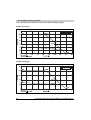
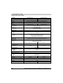
Technical Data
Different types of EnDat encoders can be used depending on the requirements:
Description
Encoder Type
Order Code (ee)
E0 1)
E1 1)
E2 2)
E3 2)
E4 3)
E5 3)
EnDat singleturn
EnDat multi-turn
EnDat singleturn
EnDat multi-turn
EnDat singleturn
EnDat multi-turn
Resolution
Recognizable
Revolutions
512 line
---
4096
Precision
Frequency Limit
32 line
4096
---
4096
±60"
±400"
±60"
≥ 100 kHz (-3 dB)
≥ 6 kHz (-3 dB)
≥ 200 kHz (-3 dB)
Manufacturer
Internet Address
Manufacturer’s
Product ID
---
512 line
Dr. Johannes Heidenhain GmbH
www.heidenhain.de
ECN1313
EQN1325
ECI1317
EQI1329
ECN1113
EQN1125
Table 3: Technical data for EnDat encoders
1) Only available for size 3 to 8 motors.
2) Only available for size 3 to 7 motors.
3) Only available for size 2 motors.
8LS Three-phase Synchronous Motors User's Manual V 1.1
23
Chapter 2
Technical Data
General Information
Technical Data • 8LS Three-phase Synchronous Motors
1.2.2 Resolver
General Information
BRX type resolvers are used in the servo motors. These resolvers are fed with a single
sinusoidal signal (reference signal) and deliver two sinusoidal signals as the result. The
amplitude of these signals change with the angular position (sine or cosine form).
Technical Data
Description
Order Code (ee)
R0
Precision
Non-linearity
± 10 angular minutes
±1 angular minute
Table 4: Technical data for the resolver
24
8LS Three-phase Synchronous Motors User's Manual V 1.1
Technical Data • 8LS Three-phase Synchronous Motors
1.3 Motor Options
•
with various rated speeds
•
with or without oil seal
•
with or without holding brake
•
with a smooth shaft or a keyed shaft
•
with two different connection directions.
The rated speed is listed as part of the model number in the form of a 3-digit code (nnn). The
code represents the rates speed divided by 100.
The respective combination of other motor options is listed in the form of a 2-digit code (ff) as
part of the model number (see section 1.3.7 "Determining the Order Code for Motor Options (ff)"
on page 32).
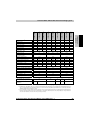
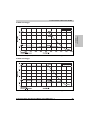
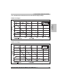
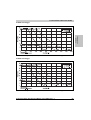
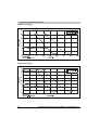
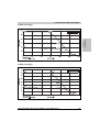
1.3.1 Rated Speed
The 8LS three-phase synchronous motors can be delivered with up to four different rated speeds
depending on the size and length. 1)
Available rated speeds nN [min-1]
Size
2000
3000
4500
2
---
---
---
3
---
Yes
---
Yes
4
---
Yes
---
Yes
5
---
6
---
7
---
8
Length
--3
Yes
5
Yes
--6
7
---
5
Yes
---
---
Yes
---
6
---
Yes
--4
---
---
Yes
---
Yes
3
---
Yes
Yes
Yes
4
6000
Yes
---
---
---
--7
3
4
5
--6
7
3
4
5
6
7
Table 5: Rated speeds available according to size and length
1) Other windings/rated speeds are possible after arrangements have been made with B&R.
8LS Three-phase Synchronous Motors User's Manual V 1.1
25
Chapter 2
Technical Data
Depending on the size and length, the 8LS three-phase synchronous motors can be delivered
Technical Data • 8LS Three-phase Synchronous Motors
1.3.2 Oil Seal
All 8LS three-phase synchronous motors are available with an optional form A oil seal according
to DIN 3760.
When equipped with an oil seal, the motors have IP65 protection according to IEC 60034-5.
Information:
Proper lubrication of the oil seal must be guaranteed throughout the entire lifespan
of the motor.
1.3.3 Holding Brake
All 8LS three-phase synchronous motors can be delivered with a holding brake. It is installed
directly behind the A flange on the motor and is used to hold the motor shaft when no power is
applied to the servo motor.
Functionality
The holding brake is controlled by the ACOPOS servo drive. It uses permanent magnets that are
demagnetized when 24 VDC is applied to a magnet winding. This releases the brake.
The brake is designed as a holding brake. It is not permitted to be used to for operational braking!
If these conditions are met, the brake has a lifespan of approximately 5,000,000 cycles (opening
and closing the brake again is one cycle).
Loaded braking during an emergency stop is permitted - but reduces the lifespan.
Information:
The required brake holding torque is determined based on the occurring load
torque. If the load torque is not sufficiently known, it is recommended to assume a
safety factor of 2.
Warning!
The holding brake is not intended for normal braking. The holding brake does not
provide protection for personnel. The maximum motor torque far exceeds the
holding torque.
26
8LS Three-phase Synchronous Motors User's Manual V 1.1
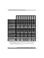
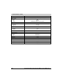
Technical Data • 8LS Three-phase Synchronous Motors
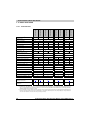
Technical data for the standard holding brake
Size of Motor
4
5
3.2
8
15
32
12
18
24
26
12000
10000
10000
10000
0.33
0.5
0.75
1
Activation Delay ton [ms]
28
29
40
Release Delay toff [ms]
14
19
7
0.12
0.38
0.19
0.3
Holding Torque MBr [Nm]
Installed Load Pon [W]
Highest Speed nmax [min-1]
Installed Current Ion [A]
2
3
2.2
8
6
7
10000
8
130
50
8000
8000
1.08
2.08
50
90
190
10
22
65
0.54
1.66
5.85
53
0.46
0.9
1.6
5.35
Installed Voltage Uon [V]
Chapter 2
Technical Data
Description
24 VDC +6 % / -10 %
Moment of Inertia JBr [kgcm²]
Weight mBr [kg]
Table 6: Technical data for the standard holding brake
Warning!
If the holding brake is not used regularly for a long period of time, we recommend
to periodically check the holding brake because the holding brake could fail in
certain environmental conditions (e.g. humidity, oil vapor).
1.3.4 Type of Shaft End
All 8LS three-phase synchronous motor shafts comply to DIN 748. They can be delivered with a
smooth shaft or a keyed shaft.
Smooth Shaft
A smooth shaft end is used for a force-fit shaft-hub connection that guarantees a zero-play
connection between shaft and hub as well as smooth operation.
Information:
For connection of pinion gears, belt disks or similar drive elements, please use
suitable clamping sets, pressure sleeves or other fastening elements.
Drive elements must be protected against unintentional removal.
The end of the shaft has a threaded center hole which can be used to remove drive elements.
8LS Three-phase Synchronous Motors User's Manual V 1.1
27
Technical Data • 8LS Three-phase Synchronous Motors
Keyed Shaft
The keyed shaft can be used for a form-fit torque transfer with low demands on the shaft-hub
connection and for handling torques with a constant direction.
The keyways for the 8LS three-phase synchronous motors conform to keyway form N1
according to DIN 6885-1. Form A shaft keys that conform to DIN 6885-1 are used. Balancing
motors with keyways is done using the half-key convention according to DIN ISO 8821.
The end of the shaft has a threaded center hole which can be used to mount drive elements with
shaft end disks.
Caution!
The shaft key can be deflected during heavy reverse operation. In extreme cases,
this can cause the shaft end to break!
Smooth shaft ends should be used preferably.
1.3.5 Load Capacity of the Shaft End and Bearing
The 8LS three-phase synchronous motors are equipped with grooved ball bearings which are
sealed on both sides and greased.
Caution!
To ensure proper lubrication of the grooved ball bearings after long storage times,
the motor shaft must be turned a few revolutions manually at least every 2 years.
The radial and axial forces (Fr , Fa) that occur on the shaft end during operation and installation
must be within the specifications listed below.
The bearing elements are not permitted to be subject to shocks or impacts! Incorrect handling
will cause the lifespan of the bearings to be reduced or the bearing to be damaged.
28
8LS Three-phase Synchronous Motors User's Manual V 1.1
Technical Data • 8LS Three-phase Synchronous Motors
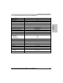
Mounting
The axial forces Fa permitted during the installation of gearboxes, pinion gears, couplings, etc.
depend on the motor size and can be found in the following table:
Motor Size
Permitted Axial Force Fa [N]
Special Motor Option "Reinforced A Side Bearing"
850
---
3
1400
---
4
2300
5050
5
2500
9500
6
2500
9500
7
5500
---
8
9500
18700
Chapter 2
Technical Data
Standard Bearing
2
Table 7: Axial forces permitted during installation
Danger!
Because of the high axial forces on the motor shaft during installation, the bearings
could be damaged and the operation of the motor holding brake could be so heavily
influenced that it has no or only a reduced braking effect. Encoder errors could also
occur.
Therefore, excessive pressure or shocks to the front shaft end or the rear housing
cover should be avoided at all costs.
Loads caused by a hammer definitely exceed the permissible values!
Operation
Radial Force
The radial force Fr on the shaft end is made up of the installation forces (e.g. belt tension on
pulleys) and operational forces (e.g. load torque on the pinion). The maximum radial force Fr
depends on the shaft end type, bearing type, average speed, position where the radial force is
applied and the desired lifespan of the bearings.
Warning!
Excessive radial force can cause premature wear on the bearings or, in extreme
cases, can cause the shaft end to break.
8LS Three-phase Synchronous Motors User's Manual V 1.1
29
Technical Data • 8LS Three-phase Synchronous Motors
Caution!
When installing drive elements on the motor shaft, avoid a hyperstatic arrangement
of the motor shaft bearings. The tolerances that occur cause additional force on the
motor shaft bearings.
This can significantly reduce the bearing's lifespan or damage the bearing!
Axial Force, Shift in Shaft Position caused by Axial Force
The axial force Fa on the shaft end is made up of the installation forces (e.g. stress caused by
installation) and operational forces (e.g. thrust caused by slanted tooth pinions). The maximum
axial force Fa depends on the bearing type and the desired lifespan of the bearings.
The fixed bearing is secured on the A flange with a retaining ring. The floating bearing is
preloaded on the B flange with a spring in the direction of the A flange. Axial forces in the
direction of the B flange can cause the spring bias to be overcome and the shaft is shifted by the
amount of axial play in the bearing (approx. 0.1 - 0.2 mm). This shift can cause problems on
motors with holding brakes or motors with EnDat encoders (E2 and E3). Therefore, no axial
force is permitted in the direction of the B flange when using these motors.
Danger!
The shaft ends of motors with holding brakes are not permitted to have axial loads
applied. Especially axial forces in the direction of the B flange should be prevented
because these forces can cause the brake to fail!
Information:
The shaft ends of motors with EnDat encoders (E2 and E3) are not permitted to have
axial loads applied. Especially axial forces in the direction of the B flange should be
prevented because these forces can cause encoder errors!
30
8LS Three-phase Synchronous Motors User's Manual V 1.1
Technical Data • 8LS Three-phase Synchronous Motors
Determining Permissible Values for Fr and Fa
Information to determine permissible values of Fr and Fa can be taken from the motor data for
the respective three-phase synchronous motors (see section 1.9 "Motor Data 8LSA2" to
section 1.15 "Motor Data 8LSA8"). Permissible values are based on a bearing lifespan of 20000
h (bearing lifespan calculation based on DIN ISO 281).
Simultaneously loading the shaft end with the maximum values of Fr and Fa is not
permitted! Contact B&R if this occurs.
1.3.6 Connection Direction
8LS three-phase synchronous motors can be delivered with "top" connection direction and also
with axial swivel connectors.
8LS Three-phase Synchronous Motors User's Manual V 1.1
31
Chapter 2
Technical Data
Warning!
Technical Data • 8LS Three-phase Synchronous Motors
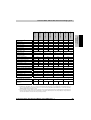
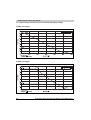
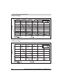
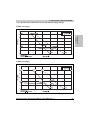
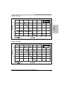
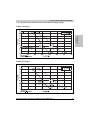
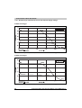
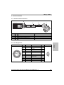
1.3.7 Determining the Order Code for Motor Options (ff)
The respective code (ff) for the order key can be found in the following table:
Motor Options
Connection Direction
Oil Seal
Code for Order Key (ff)
Holding brake
No
No
Normal
Straight (upwards)
No
Yes
Normal
No
No
Normal
Angled (swivel
connector)
No
Yes
Normal
Shaft End
Smooth
C0
Keyed
C1
Smooth
C2
Keyed
C3
Smooth
C6
Keyed
C7
Smooth
C8
Keyed
C9
Smooth
D0
Keyed
D1
Smooth
D2
Keyed
D3
Smooth
D6
Keyed
D7
Smooth
D8
Keyed
D9
Table 8: Order key code (ff) for the motor options
32
8LS Three-phase Synchronous Motors User's Manual V 1.1
Technical Data • 8LS Three-phase Synchronous Motors
1.4 Special Motor Options
The 8LS three-phase synchronous motors can be delivered with the following special motor
options depending on the cooling type, size and length: 1)
•
"Reinforced A side bearing"
1.4.1 "Reinforced A side bearing"
8LS three-phase synchronous motors with special motor option "reinforced A side bearing" can
handle increased radial and axial forces (Fr , Fa) on the end of the shaft.
Information to determine permissible values of Fr and Fa can be taken from the motor data for
the respective 8LS three-phase synchronous motors (see section 1.9 "Motor Data 8LSA2" to
section 1.15 "Motor Data 8LSA8").
The following motor sizes are available with special motor option "reinforced A side bearing":
Available for Motor Size
Special Motor Option
Code (gg)
2
3
4
5
6
7
8
04
---
---
Yes
Yes
Yes
---
Yes
"Reinforced A side bearing"
Table 9: Available motor sizes for special motor option "reinforced A side bearing"
Information:
Motors with special motor option "reinforced A side bearing" have increased values
(in relation to motors with standard bearings) for the dimensions of the motor shaft.
The exact dimensions can be found in the motor data for the respective 8LS threephase synchronous motors (see section 1.9 "Motor Data 8LSA2" to section 1.15
"Motor Data 8LSA8").
1) Other special options must be arranged with B&R.
8LS Three-phase Synchronous Motors User's Manual V 1.1
33
Chapter 2
Technical Data
The respective special motor option is listed as part of the model number in the form of a 2-digit
code (gg). "00" has to be entered if no special motor options are required.
Technical Data • 8LS Three-phase Synchronous Motors
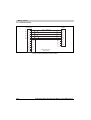
1.5 Order Key
8LS
b
c
d
.
ee
nnn
ff
gg
-
h
Cooling type (see section 1.1.1 "Cooling Types" on page 22)
A ...... self-cooling (no separate surface cooling)
Size (see section 1.1.2 "Sizes" on page 22)
Valid values: 2, 3, 4, 5, 6, 7, 8
Length (see section 1.1.3 "Lengths" on page 22)
3 ......
4 ......
5 ......
6 ......
7 ......
small rated torque
medium rated torque
large rated torque
extra large rated torque
exceptionally large rated torque
Encoder system (see section 1.2 "Motor Encoder Systems" on page 23)
E0 .....EnDat single-turn, 512 lines (ECN1313) 1)
E1 .....EnDat multi-turn, 512 lines (EQN1325), 4096 revolutions 1)
E2 .....EnDat single-turn, 32 lines, inductive (ECI1317) 2)
E3 .....EnDat multi-turn, 32 lines, inductive (EQI1329), 4096 revolutions 2)
E4 .....EnDat single-turn, 512 lines (ECN1113) 3)
E5 .....EnDat multi-turn, 512 lines (EQN1125), 4096 revolutions 3)
R0 .....Resolver
1) Only available for size 3 to 8 motors.
2) Only available for size 3 to 7 motors.
3) Only available for size 2 motors.
Rated speed (see section 1.3 "Motor Options" on page 25)
nnn ......rated speed / 100; e.g.: 030 corresponds to a rated speed of 3000 min-1
Motor Options (see section 1.3 "Motor Options" on page 25)
Special Motor Options (see section 1.4 "Special Motor Options" on page 33) 1)
00 ..... No special motor options
04 ..... Reinforced A side bearing 2)
1) Special motor options must be arranged with B&R.
2) Not available in combination with motor option „Holding brake“.
Motor Version
Valid values: 0
34
8LS Three-phase Synchronous Motors User's Manual V 1.1
Technical Data • 8LS Three-phase Synchronous Motors
1.5.1 Example Order 1
A three-phase synchronous motor (type 8LSA45) with a nominal speed of 3000 min-1 was
selected for an application. Because of the construction, the cables can only be connected on
the top of the motor ("top" connection direction). The motor should also be equipped with a
holding brake, a keyed shaft and a 512 line EnDat single-turn encoder.
The code (nnn) for a rated speed of 3000 min-1 is 030.
The code (ff) for the other options (oil seal, holding brake, keyed shaft and connection direction)
is C3 (see table 8 "Order key code (ff) for the motor options" on page 32).
Therefore the model number for the motor required is: 8LSA45.E0030C300-0
1.5.2 Example Order 2
A three-phase synchronous motor (type 8LSA56) with a nominal speed of 4500 min-1 was
selected for an application. Because of the construction, the cables can only be connected on
the back of the motor (swivel connectors). The motor should also be equipped with a holding
brake, a smooth shaft, an oil seal and a 512 line EnDat multi-turn encoder.
The code (ee) for the encoder system is E1 (see table 3 "Technical data for EnDat encoders" on
page 23).
The code (nnn) for a rated speed of 4500 min-1 is 045.
The code (ff) for the other options (oil seal, holding brake, keyed shaft and connection direction)
is D8 (see table 8 "Order key code (ff) for the motor options" on page 32).
Therefore the model number for the motor required is: 8LSA56.E1045D800-0
8LS Three-phase Synchronous Motors User's Manual V 1.1
35
Chapter 2
Technical Data
The code (ee) for the encoder system is E0 (see table 3 "Technical data for EnDat encoders" on
page 23).
Technical Data • 8LS Three-phase Synchronous Motors
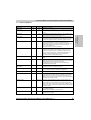
1.6 General Motor Data
Description
Cooling Type A
General Information
C-UR-US Listed
Yes
Electrical Characteristics
Mains Input Voltage on Servo Drive
3 x 400 VAC ... 3 x 480 VAC ± 10 %
Connection Technology
Motor Connector
Encoder Connection
Circular connector from Intercontec
Size 1 (8LSA8: Size 1.5)
Size 1
Thermal Characteristics
Insulation Class according to IEC 60034-1
F
Methods of Cooling according to IEC 60034-6
(IC code)
Self-cooling
No separate surface cooling (IC4A0A0)
Thermal Motor Protection according to
IEC 60034-11
Maximum winding temperature is 145 °C
(limited to 110 °C by the thermal motor protection in ACOPOS servo drive)
Mechanical Characteristics
Vibration severity grade R 1)
Vibration Severity according to IEC 60034-14
Roller Bearing, Dynamic Load Ratings and Rated
Lifespan
Based on DIN ISO 281
Eye Bolt according to DIN 580
For size 8
Shaft End according to DIN 748 2)
Form E
Oil Seal according to DIN 3760
Form A
Key and Keyway according to DIN 6885-1
Keyway form N1; key form A
Balancing the Shaft according to DIN ISO 8821
Half-key arrangement
Mounting Flange according to DIN 42948
Form A
Shaft End Concentricity, Coaxial Properties and
Mounting Flange Plane according to DIN 42955
Tolerance R
Paint
Description
Color
Water-based paint
98160 *IDROLIN/E SM SEMIOPACO NERO RAL 9005-C.452
RAL 9005 flat; shaft end and flange front metallic glossy
Operational Conditions
Rating Class, Operation Mode acc. to IEC 60034-1
S1 - continuous operation
Environmental temperature during operation
-15 °C to +40 °C
Reduction of the Rated Current and Stall Current at
Temperatures above 40 °C
10 % per 10 °C
+55 °C 3)
Maximum Environmental Temperature during
Operation
Relative Humidity During Operation
5 to 95% (non-condensing)
Reduction of the Nominal Current and Stall Current
at Installation Altitudes over 1000 m above Sea
Level
Maximum Installation Altitude
10 % per 1000 m
2000 m 4)
Table 10: General technical data
36
8LS Three-phase Synchronous Motors User's Manual V 1.1
Technical Data • 8LS Three-phase Synchronous Motors
Description
Cooling Type A
Maximum Flange Temperature
65 °C
Protection Standards according to IEC 60034-5
(IP code)
With Optional Oil Seal
IP64
IP65
Construction and Mounting Arrangement Type
according to IEC 60034-7
(IM code)
Horizontal (IM3001)
Vertical, motor hangs on the machine (IM3011)
Vertical, motor stands on the machine (IM3031)
Storage Temperature
Relative Humidity during Storage
Transport Temperature
Relative Humidity during Transport
Chapter 2
Technical Data
Storage and Transport Conditions
-20 to +60 °C
Max. 90%, non-condensing
-20 to +60 °C
Max. 90%, non-condensing
Table 10: General technical data (cont.)
1) Valid for all motors with a shaft height of more than 56 mm.
2) Except motor sizes 2 and 7.
3) Continuous operation of the servo motors at environmental temperatures from +40 °C to max. +55 °C is possible, but results in a shorter
lifespan.
4) Additional requirements are to be arranged with B&R.
8LS Three-phase Synchronous Motors User's Manual V 1.1
37
Technical Data • 8LS Three-phase Synchronous Motors
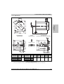
1.7 Terminology and Formula Symbols
1.7.1 Connection Direction, Bearing
Angled (swivel connector)
Connector facing top
Swivel connector
A bearing
Straight (upwards)
B bearing
Table 11: Connection direction terminology, bearings
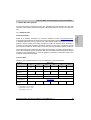
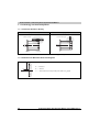
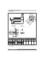
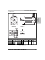
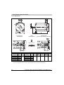
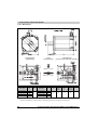
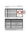
1.7.2 Definitions for Maximum Shaft Load Diagrams
x
Fr
Fa
Fr ............Radial force
Fa ............Axial force
x ..............Distance between motor flange and the point the radial force Fr is applied
Figure 6: Definitions for maximum shaft load diagrams
38
8LS Three-phase Synchronous Motors User's Manual V 1.1
Technical Data • 8LS Three-phase Synchronous Motors
Symbol
Unit
Description
Rated speed
Term
nN
min-1
Rated Speed of the Motor
Rated torque
MN
Nm
The rated torque is output by the motor (n = nN) when the rated current is being
drawn. This is possible for any length of time if the environmental conditions are
correct.
Rated power
PN
kW
The rated power is output by the motor when n = nN. This is possible for any
length of time if the environmental conditions are correct.
Rated current
IN
A
Stall torque
M0
Nm
Stall current
I0
A
The "stall current" is the effective value of the phase current (current in the motor
supply line) for the generation of the "stall torque" at the speed n0. This is
possible for any length of time if the environmental conditions are correct.
The speed n0 must be high enough so that the winding temperature in all
windings is uniform and stationary (n0 = 50 min-1 for B&R motors).
The continuous current is reduced while stationary.
Peak torque
Mmax
Nm
The peak torque is briefly output by the motor when the peak current is being
drawn.
Maximum current
Imax
A
The peak current is the effective value of the phase current (current in the motor
supply line) for the generation of the peak torque. Only possible for a short time.
The peak current is determined by the magnetic circuit.
Exceeding this value for a short time can cause irreversible damage
(demagnetize the magnet material).
a
rad/s²
Maximum acceleration of the motor without load and without brake. Value for
the dynamics of the motor (corresponds to Mmax / J).
Maximum speed
nmax
min-1
Maximum motor speed.
This is a mechanical condition (centrifugal force, bearing wear).
Average speed
naver
min-1
Average speed for one cycle
Torque constant
KT
Nm/A
The torque constant determines the torque created by the motor with 1 Arms
phase current. This value applies at a motor temperature of 20°C. When the
temperature increases, the torque constant is reduced (generally to 10%).
When the current increases, the torque constant is reduced (generally starting
at twice the value of the rated current).
Voltage constant
KE
V/1000min-1
The voltage constant determines the effective value (phase-phase) of the
reverse voltage (EMF) induced by the motor with a speed of 1000 min-1.
This value applies at a motor temperature of 20°C. When the temperature
increases, the voltage constant is reduced (generally to 5 %). When the current
increases, the voltage constant is reduced (generally starting at twice the value
of the rated current).
Stator resistance
R2ph
Ω
Resistance measured in ohms between two motor leads (phase-phase) at
20 °C winding temperature.
On B&R motors, the windings use a star connection.
Stator inductance
L2ph
mH
Winding inductance measured between two motor leads. Stator inductance
depends on the rotor position.
Maximum angular acceleration
without brake
The rated current is the effective value for the phase current (current in the
motor supply line) when generating the rated torque at the rated speed. This is
possible for any length of time if the environmental conditions are correct.
The "stall torque" is output by the motor at the speed n0 and when the "stall
current" is being drawn. This is possible for any length of time if the
environmental conditions are correct. The speed n0 must be high enough so
that the winding temperature in all windings is uniform and stationary
(n0 = 50 min-1 for B&R motors).
The continuous torque is reduced while stationary.
Table 12: Formula symbols
8LS Three-phase Synchronous Motors User's Manual V 1.1
39
Chapter 2
Technical Data
1.7.3 Formula Symbols
Technical Data • 8LS Three-phase Synchronous Motors
Term
Symbol
Unit
Description
Electrical time constant
tel
ms
Corresponds to 1/5 of the time needed for the stator current to stabilize with
constant operating conditions.
Thermal time constant
ttherm
min
Corresponds to 1/5 of the time needed for the motor temperature to stabilize
with constant operating conditions.
Moment of inertia without brake
J
kgcm²
Weight without brake
m
kg
Moment of inertia of brake
JBr
kgcm²
Moment of inertia for the motor without holding brake.
Weight of the motor without holding brake.
Moment of inertia for the built-in holding brake.
Weight of brake
mBr
kg
Weight of the built-in holding brake.
Brake holding torque
MBr
Nm
Minimum torque required to hold the rotor when the brake is activated.
Installed load
Pin
W
Installed load for the built-in holding brake.
Installed current
Iin
A
Installed current for the built-in holding brake.
Installed voltage
Uin
V
Operating voltage for the built-in holding brake.
Activation delay
ton
ms
Delay time required for the holding torque of the brake to be established after
the operating voltage has been removed from the holding brake.
Release delay
toff
ms
Delay time required until the holding torque of the holding brake is reduced by
90% (the brake is released) after the operating voltage has been returned to the
holding brake.
Table 12: Formula symbols (cont.)
40
8LS Three-phase Synchronous Motors User's Manual V 1.1
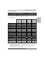
Technical Data • Motor Data Overview Cooling Type A
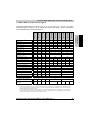
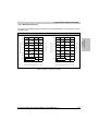
1.8 Motor Data Overview Cooling Type A
8LSA25.ee060ffgg-0
8LSA26.ee060ffgg-0
8LSA33.ee030ffgg-0
8LSA33.ee045ffgg-0
8LSA33.ee060ffgg-0
8LSA34.ee030ffgg-0
8LSA34.ee045ffgg-0
8LSA34.ee060ffgg-0
6000
6000
6000
6000
3000
4500
6000
3000
4500
6000
4
4
4
4
4
4
Rated Torque MN [Nm]
0.17
0.35
0.52
0.69
0.7
0.67
0.6
1.4
1.3
1
Rated Power PN [kW]
0.11
0.22
0.33
0.43
0.22
0.32
0.38
0.44
0.61
0.63
0.48
0.69
0.82
0.96
1.34
1.37
Rated Current IN [A]
0.23
0.48
0.71
0.95
Stall Torque M0 [Nm]
0.2
0.4
0.6
0.8
Stalled Current I0 [A]
0.27
0.55
0.82
1.1
Peak Torque Mmax [Nm]
0.8
1.6
2.4
3.2
1.25
2.5
3.7
5
Maximum Angular Acceleration
without Brake a [rad/s²]
Peak Current Imax [A]
114286
133333
150000
160000
Maximum Speed nmax [min-1]
0.75
0.52
0.77
1.5
1.03
1.03
3
2.22
3.32
1.55
2.06
6
4.43
4.43
85714
6.65
8.87
100000
12000
12000
12000
12000
Torque Constant KT [Nm/A]
0.73
0.73
0.73
0.73
1.46
12000
0.97
0.73
1.46
12000
0.97
0.73
Voltage Constant KE [V/1000 min-1]
43.98
43.98
43.98
43.98
87.96
58.64
43.98
87.96
58.64
43.98
Stator Resistance R2ph [Ω]
190
62
29
20.8
116.9
44.48
27
34
15.56
8.5
Stator Inductance L2ph [mH]
150
75
49.7
37.5
147.5
63.08
36.87
73.12
32.77
18.28
Electrical Time Constant tel [ms]
0.79
1.21
1.71
1.8
1.26
1.4
1.37
2.15
2.2
2.15
15
20
25
30
32
Moment of Inertia without Brake J [kgcm²]
0.07
0.12
0.16
0.2
0.35
0.6
Weight without Brake m [kg]
1.5
1.7
1.9
2.1
1.4
2.2
Moment of Inertia for Brake JBr [kgcm²]
0.12
0.12
0.12
0.12
0.38
0.38
Weight of Brake mBr [kg]
0.19
0.19
0.19
0.19
0.3
0.3
Holding Torque of the Brake MBr [Nm]
2.2
2.2
2.2
2.2
3.2
3.2
Recommended Cable Cross Section for
B&R Motor Cables [mm²] 1)
1.5
99
1.5
99
1.5
99
1.5
99
1.5
99
1.5
99
Recommended ACOPOS Servo Drive
8Vxxxx.00-x 2)
1010
1010
1010
1016
Thermal Time Constant ttherm [min]
1010
35
1016
1016
1022
1045
Table 13: Motor data overview for cooling type A
1) The B&R motor cables with this cable cross section are produced optimally (cables stripped to the correct length) for the recommended ACOPOS servo
drives (see next line). B&R motor cables with other cable cross sections can also be used (within the specified terminal cross section range) and can be
obtained from B&R in the desired design on request.
2) The recommended servo drive is defined for the stall current of the motor; if more than double the stall torque is required during the acceleration phase, the
next larger servo drive should be selected. This recommendation is only a guideline, detailed inspection of the corresponding speed - torque characteristic
curve can result in deviations of the servo drive size (one size larger or smaller).
8LS Three-phase Synchronous Motors User's Manual V 1.1
41
Chapter 2
Technical Data
8LSA24.ee060ffgg-0
Rated Speed nN [min-1]
Number of Poles
8LSA23.ee060ffgg-0
The technical data listed in this section (KE, KT, IN, I0, Imax, R2ph, L2ph, tel, ttherm, m, J) has a
theoretical tolerance range of ±10 %. This is also valid for the speed - torque characteristic
curves represented in the following sections.
8LSA35.ee045ffgg-0
8LSA35.ee060ffgg-0
8LSA36.ee030ffgg-0
8LSA36.ee045ffgg-0
8LSA36.ee060ffgg-0
8LSA43.ee030ffgg-0
8LSA43.ee045ffgg-0
8LSA43.ee060ffgg-0
Rated Speed nN [min-1]
8LSA35.ee030ffgg-0
Technical Data • Motor Data Overview Cooling Type A
3000
4500
6000
3000
4500
6000
3000
4500
6000
Number of poles
4
4
10
Rated Torque MN [Nm]
2.1
1.8
1.6
2.7
2.2
1.8
3.1
2.7
2
Rated Power PN [kW]
0.66
0.85
1.01
0.85
1.04
1.13
0.97
1.27
1.26
Rated Current IN [A]
1.44
1.86
2.20
1.86
2.27
2.47
1.9
2.49
2.46
Stall Torque M0 [Nm]
2.3
Stalled Current I0 [A]
1.58
Peak Torque Mmax [Nm]
2.37
3
3.16
2.07
3.09
9.2
Peak Current Imax [A]
6.8
10.2
Maximum Angular Acceleration
without Brake a [rad/s²]
4.12
2.46
3.7
12
13.6
8.9
13.3
102222
Maximum Speed nmax [min-1]
4
17.73
14.6
21.9
100000
12000
4.91
15.2
29.2
91429
12000
12000
Torque Constant KT [Nm/A]
1.46
0.97
0.73
1.45
0.97
0.73
1.63
1.08
0.81
Voltage Constant KE [V/1000 min-1]
87.96
58.64
43.98
87.96
58.64
43.98
98.43
65.45
49.22
1.36
Stator Resistance R2ph [Ω]
19
8.1
4.5
11.45
5.16
2.9
5.43
2.42
Stator Inductance L2ph [mH]
49.16
21.70
12.29
36.5
16.64
9.45
36.5
16.5
9.2
Electrical Time Constant tel [ms]
2.59
2.68
2.73
3.19
3.23
3.26
6.72
6.83
6.77
Thermal Time Constant ttherm [min]
38
40
25
Moment of Inertia without Brake J [kgcm²]
0.9
1.2
1.87
Weight without Brake m [kg]
3.1
4
3.9
Moment of Inertia for Brake JBr [kgcm²]
0.38
0.38
0.54
Weight of Brake mBr [kg]
0.29
0.29
0.46
Holding Torque of the Brake MBr [Nm]
3.2
3.2
8
1.5
99
1.5
99
1.5
99
Recommended Cable Cross Section for
B&R Motor Cables [mm²] 1)
Recommended ACOPOS Servo Drive
8Vxxxx.00-x 2)
1022
1045
1045
1045
1090
1045
1090
Table 14: Motor data overview for cooling type A (cont.)
1) The B&R motor cables with this cable cross section are produced optimally (cables stripped to the correct length) for the recommended ACOPOS servo
drives (see next line). B&R motor cables with other cable cross sections can also be used (within the specified terminal cross section range) and can be
obtained from B&R in the desired design on request.
2) The recommended servo drive is defined for the stall current of the motor; if more than double the stall torque is required during the acceleration phase, the
next larger servo drive should be selected. This recommendation is only a guideline, detailed inspection of the corresponding speed - torque characteristic
curve can result in deviations of the servo drive size (one size larger or smaller).
42
8LS Three-phase Synchronous Motors User's Manual V 1.1
8LSA44.ee060ffgg-0
8LSA45.ee030ffgg-0
8LSA45.ee045ffgg-0
8LSA45.ee060ffgg-0
8LSA46.ee030ffgg-0
8LSA46.ee045ffgg-0
8LSA46.ee060ffgg-0
3000
4500
6000
3000
4500
6000
3000
4500
6000
Number of Poles
10
10
10
Rated Torque MN [Nm]
4.62
3.6
3
6.16
4.8
4
7.7
6
5
Rated Power PN [kW]
1.45
1.7
1.88
1.94
2.26
2.51
2.42
2.83
3.14
Rated Current IN [A]
2.84
3.33
3.69
3.78
4.43
4.91
4.73
5.54
6.14
Stall Torque M0 [Nm]
6
Stalled Current I0 [A]
3.69
Peak Torque Mmax [Nm]
8
5.54
7.37
4.91
7.39
22.8
Peak Current Imax [A]
21.9
Maximum Angular Acceleration
without Brake a [rad/s²]
9.83
6.14
30.4
32.9
43.8
29.2
43.9
94118
Maximum Speed nmax [min-1]
10
12.28
38
58.3
36.5
95522
12000
9.24
54.8
72.9
97561
12000
12000
Torque Constant KT [Nm/A]
1.63
1.08
0.81
1.63
1.08
0.81
1.63
1.08
0.81
Voltage Constant KE [V/1000 min-1]
98.43
65.45
49.22
98.43
65.45
49.22
98.43
65.45
49.22
Stator Resistance R2ph [Ω]
3.45
1.53
0.86
2.49
1.11
0.67
1.92
0.88
0.48
Stator Inductance L2ph [mH]
24
10.8
6.2
21.8
9.69
5.45
17.44
7.75
4.36
6.96
7.04
7.19
8.76
8.76
8.13
9.08
8.81
9.08
Electrical Time Constant tel [ms]
Thermal Time Constant ttherm [min]
30
35
40
Moment of Inertia without Brake J [kgcm²]
2.73
3.58
4.39
Weight without Brake m [kg]
5.26
6.7
8.1
Moment of Inertia for Brake JBr [kgcm²]
0.54
0.54
0.54
Weight of Brake mBr [kg]
0.46
0.46
0.46
8
8
8
Holding Torque of the Brake MBr [Nm]
Recommended Cable Cross Section for
B&R Motor Cables [mm²] 1)
Recommended ACOPOS Servo Drive
8Vxxxx.00-x 2)
1.5
99
1045
1090
1.5
99
4
99
1.5
99
4
99
1090
1180
1090
1180
Table 15: Motor data overview for cooling type A (cont.)
1) The B&R motor cables with this cable cross section are produced optimally (cables stripped to the correct length) for the recommended ACOPOS servo
drives (see next line). B&R motor cables with other cable cross sections can also be used (within the specified terminal cross section range) and can be
obtained from B&R in the desired design on request.
2) The recommended servo drive is defined for the stall current of the motor; if more than double the stall torque is required during the acceleration phase, the
next larger servo drive should be selected. This recommendation is only a guideline, detailed inspection of the corresponding speed - torque characteristic
curve can result in deviations of the servo drive size (one size larger or smaller).
8LS Three-phase Synchronous Motors User's Manual V 1.1
43
Chapter 2
Technical Data
8LSA44.ee045ffgg-0
Rated Speed nN [min-1]
8LSA44.ee030ffgg-0
Technical Data • Motor Data Overview Cooling Type A
4500
3000
8
8LSA57.ee045ffgg-0
3000
8LSA57.ee030ffgg-0
4500
8
8LSA56.ee045ffgg-0
3000
8LSA56.ee030ffgg-0
4500
8
8LSA55.ee045ffgg-0
3000
8LSA55.ee030ffgg-0
4500
8
8LSA54.ee045ffgg-0
3000
8LSA54.ee030ffgg-0
Rated Speed nN [min-1]
Number of Poles
8LSA53.ee045ffgg-0
8LSA53.ee030ffgg-0
Technical Data • Motor Data Overview Cooling Type A
4500
8
Rated Torque MN [Nm]
3.5
3
7
6
10.5
9
14
12
17.5
15
Rated Power PN [kW]
1.1
1.41
2.2
2.83
3.3
4.24
4.4
5.65
5.5
7.07
Rated Current IN [A]
2.15
2.73
4.29
5.45
6.44
8.18
8.59
10.91
10.74
Stall Torque M0 [Nm]
4
Stalled Current I0 [A]
2.45
8
3.64
Peak Torque Mmax [Nm]
4.91
12
Peak Current Imax [A]
11.3
22
30000
Maximum Speed nmax [min-1]
7.27
7.36
24
15.9
Maximum Angular Acceleration
without Brake a [rad/s²]
12
10.91
9.82
36
33.3
33.8
40000
9000
16
9000
14.55
12.27
48
47.6
45
45000
18.18
60
62.3
53.1
48000
9000
13.64
20
79.7
50420
9000
9000
Torque Constant KT [Nm/A]
1.63
1.1
1.63
1.1
1.63
1.1
1.63
1.1
1.63
1.1
Voltage Constant KE [V/1000 min-1]
98.43
65.97
98.43
65.97
98.43
65.97
98.43
65.97
98.43
65.97
Stator Resistance R2ph [Ω]
9.72
4.97
3.1
1.32
1.6
0.8
1.07
0.56
0.89
0.39
Stator Inductance L2ph [mH]
55.4
28.4
23.34
9.02
14.01
7.03
10.51
5.48
8.5
3.78
Electrical Time Constant tel [ms]
5.7
5.71
7.53
6.83
8.76
8.79
9.82
9.84
9.55
Thermal Time Constant ttherm [min]
36
Moment of Inertia without Brake J [kgcm²]
40
43
48
9.69
50
4
6
8
10
11.9
Weight without Brake m [kg]
10.2
12
14.1
16.4
18.6
Moment of Inertia for Brake JBr [kgcm²]
1.66
1.66
1.66
1.66
1.66
Weight of Brake mBr [kg]
0.9
0.9
0.9
0.9
0.9
Holding Torque of the Brake MBr [Nm]
15
15
15
15
15
Recommended Cable Cross Section for
B&R Motor Cables [mm²] 1)
1.5
99
1.5
99
1.5
99
4
99
4
99
4
99
Recommended ACOPOS Servo Drive
8Vxxxx.00-x 2)
1045
1090
1090
1180
1180
1180
1320
Table 16: Motor data overview for cooling type A (cont.)
1) The B&R motor cables with this cable cross section are produced optimally (cables stripped to the correct length) for the recommended ACOPOS servo
drives (see next line). B&R motor cables with other cable cross sections can also be used (within the specified terminal cross section range) and can be
obtained from B&R in the desired design on request.
2) The recommended servo drive is defined for the stall current of the motor; if more than double the stall torque is required during the acceleration phase, the
next larger servo drive should be selected. This recommendation is only a guideline, detailed inspection of the corresponding speed - torque characteristic
curve can result in deviations of the servo drive size (one size larger or smaller).
44
8LS Three-phase Synchronous Motors User's Manual V 1.1
3000
4500
8
Rated Torque MN [Nm]
11.6
8.9
17.5
10.6
21
10.9
23.2
12
Rated Power PN [kW]
3.64
4.19
5.5
5
6.6
5.14
7.29
5.65
Rated Current IN [A]
7.12
8.09
10.74
9.64
12.88
9.91
14.23
Stall Torque M0 [Nm]
12
Stalled Current I0 [A]
7.36
Peak Torque Mmax [Nm]
20
10.91
12.27
40.8
Peak Current Imax [A]
44
Maximum Angular Acceleration
without Brake a [rad/s²]
62
18.18
69
51000
Maximum Speed nmax [min-1]
24
14.72
68
104
6000
21.82
17.18
25.45
95.2
87
130
104
59130
6000
10.91
28
81.6
57143
149
60637
6000
6000
Torque Constant KT [Nm/A]
1.63
1.
1.63
1.1
1.63
1.1
1.63
1.1
Voltage Constant KE [V/1000 min-1]
98.43
65.97
98.43
65.97
98.43
65.97
98.43
65.97
Stator Resistance R2ph [Ω]
1.6
0.8
0.89
0.39
0.65
0.29
0.5
0.25
Stator Inductance L2ph [mH]
14.01
7.03
8.5
3.78
6.53
2.9
5.29
2.59
Electrical Time Constant tel [ms]
8.76
8.79
9.55
9.69
10.05
10.14
10.58
Thermal Time Constant ttherm [min]
Moment of Inertia without Brake J [kgcm²]
10.57
45
50
55
60
8
11.9
13.8
15.7
Weight without Brake m [kg]
14.1
18.6
20.8
23
Moment of Inertia for Brake JBr [kgcm²]
5.85
5.85
5.85
5.85
Weight of Brake mBr [kg]
1.6
1.6
1.6
1.6
Holding Torque of the Brake MBr [Nm]
32
32
32
32
4
99
4
99
4
99
Recommended Cable Cross Section for
B&R Motor Cables [mm²] 1)
1.5
99
4
99
Recommended ACOPOS Servo Drive
8Vxxxx.00-x 2)
1090
1180
1180
1320
Chapter 2
Technical Data
4500
8
8LSA66.ee045ffgg-0
3000
8LSA66.ee030ffgg-0
4500
8
8LSA65.ee045ffgg-0
3000
8LSA65.ee030ffgg-0
4500
8
8LSA64.ee045ffgg-0
3000
8LSA64.ee030ffgg-0
Rated Speed nN [min-1]
Number of Poles
8LSA63.ee045ffgg-0
8LSA63.ee030ffgg-0
Technical Data • Motor Data Overview Cooling Type A
1180
1320
1180
1320
Table 17: Motor data overview for cooling type A (cont.)
1) The B&R motor cables with this cable cross section are produced optimally (cables stripped to the correct length) for the recommended ACOPOS servo
drives (see next line). B&R motor cables with other cable cross sections can also be used (within the specified terminal cross section range) and can be
obtained from B&R in the desired design on request.
2) The recommended servo drive is defined for the stall current of the motor; if more than double the stall torque is required during the acceleration phase, the
next larger servo drive should be selected. This recommendation is only a guideline, detailed inspection of the corresponding speed - torque characteristic
curve can result in deviations of the servo drive size (one size larger or smaller).
8LS Three-phase Synchronous Motors User's Manual V 1.1
45
8LSA85.ee020ffgg-0
8LSA85.ee020ffgg-0
20
8LSA84.ee030ffgg-0
Rated Torque MN [Nm]
8LSA83.ee030ffgg-0
3000
8LSA75.ee030ffgg-0
4500
6
8LSA74.ee045ffgg-0
3000
8LSA74.ee030ffgg-0
Rated Speed nN [min-1]
Number of Poles
8LSA73.ee045ffgg-0
8LSA73.ee030ffgg-0
Technical Data • Motor Data Overview Cooling Type A
4500
3000
3000
3000
2000
2000
6
6
6
6
6
15
30
27
48.4
72
85
6
14.5
24
Rated Power PN [kW]
6.28
6.83
7.54
7.07
9.42
8.48
15.21
15.08
17.8
Rated Current IN [A]
12.27
13.18
14.72
13.64
18.4
16.56
29.69
29.39
34.69
40
40
69
94
115
23.64
19.63
29.09
24.54
24.54
42.33
38.37
46.94
187
120
204
280
345
171
140
176
102
171
150.6
182
13357
18462
17895
18667
17969
3600
Stall Torque M0 [Nm]
26
Stalled Current I0 [A]
15.95
Peak Torque Mmax [Nm]
32
107
Peak Current Imax [A]
115
Maximum Angular Acceleration
without Brake a [rad/s²]
134
10918
Maximum Speed nmax [min-1]
207
11652
4500
3600
3600
3600
Torque Constant KT [Nm/A]
1.63
6000
1.1
1.63
6000
1.1
1.63
1.63
1.63
2.45
2.45
Voltage Constant KE [V/1000 min-1]
98.43
65.97
98.43
65.97
98.43
98.43
98.43
147.65
147.65
0.12
Stator Resistance R2ph [Ω]
0.46
0.22
0.34
0.16
0.2
0.23
0.1
0.16
Stator Inductance L2ph [mH]
5.55
2.62
4.42
2.2
3.07
5.4
3.11
5.18
4.04
Electrical Time Constant tel [ms]
12.07
11.91
13
13.75
15.35
23.48
31.1
32.38
34.83
Thermal Time Constant ttherm [min]
55
60
65
50
65
80
90
Moment of Inertia without Brake J [kgcm²]
98
115
140
65
114
150
192
Weight without Brake m [kg]
27
30
38
41.5
55
74
92
Moment of Inertia for Brake JBr [kgcm²]
5.85
5.85
5.85
53
53
53
53
Weight of Brake mBr [kg]
1.6
1.6
1.6
5.35
5.35
5.35
5.35
Holding Torque of the Brake MBr [Nm]
32
32
32
130
130
130
130
4
99
4
99
4
99
4 2)
10
100
10
100
10
100
1320
1320
1320
1640
1640
1640
Recommended Cable Cross Section for
B&R Motor Cables [mm²] 1)
Recommended ACOPOS Servo Drive
8Vxxxx.00-x 3)
1180
1320
Table 18: Motor data overview for cooling type A (cont.)
1) The B&R motor cables with this cable cross section are produced optimally (cables stripped to the correct length) for the recommended ACOPOS servo
drives (see next line). B&R motor cables with other cable cross sections can also be used (within the specified terminal cross section range) and can be
obtained from B&R in the desired design on request.
2) Special prefabricated motor cables must be used for this motor / servo drive combination (size of the motor plug is not the standard size). They are available
from B&R on request.
3) The recommended servo drive is defined for the stall current of the motor; if more than double the stall torque is required during the acceleration phase, the
next larger servo drive should be selected. This recommendation is only a guideline, detailed inspection of the corresponding speed - torque characteristic
curve can result in deviations of the servo drive size (one size larger or smaller).
46
8LS Three-phase Synchronous Motors User's Manual V 1.1
Technical Data • Motor Data 8LSA2
1.9 Motor Data 8LSA2
Preferred type 1)
Without holding brake
8LSA25.R0060D000-0
With holding brake
8LSA25.R0060D200-0
1) Preferred types have increased availability for first orders, and conveniance when service is needed. They are equipped as follows:
z Rated speed 6000 min-1 z Resolver z Smooth shaft z Angled connection (swivel connector).
8LSA24.ee060ffgg-0
8LSA25.ee060ffgg-0
8LSA26.ee060ffgg-0
6000
6000
6000
6000
4
4
4
4
Rated Torque MN [Nm]
0.17
0.35
0.52
0.69
Rated Power PN [kW]
0.11
0.22
0.33
0.43
Rated Current IN [A]
0.23
0.48
0.71
0.95
0.8
Rated Speed nN [min-1]
Number of Poles
Stall Torque M0 [Nm]
0.2
0.4
0.6
Stalled Current I0 [A]
0.27
0.55
0.82
1.1
Peak Torque Mmax [Nm]
0.8
1.6
2.4
3.2
Peak Current Imax [A]
1.25
2.5
3.7
5
Maximum Angular Acceleration
without Brake a [rad/s²]
114286
133333
150000
160000
Maximum Speed nmax [min-1]
12000
12000
12000
12000
Torque Constant KT [Nm/A]
0.73
0.73
0.73
0.73
Voltage Constant KE [V/1000 min-1]
43.98
43.98
43.98
43.98
Stator Resistance R2ph [Ω]
190
62
29
20.8
Stator Inductance L2ph [mH]
150
75
49.7
37.5
Electrical Time Constant tel [ms]
0.79
1.21
1.71
1.8
15
20
25
30
Moment of Inertia without Brake J [kgcm²]
0.07
0.12
0.16
0.2
Weight without Brake m [kg]
1.5
1.7
1.9
2.1
Thermal Time Constant ttherm [min]
Moment of Inertia for Brake JBr [kgcm²]
0.12
0.12
0.12
0.12
Weight of Brake mBr [kg]
0.19
0.19
0.19
0.19
Holding Torque of the Brake MBr [Nm]
2.2
2.2
2.2
2.2
Recommended Cable Cross Section for
B&R Motor Cables [mm²] 1)
1.5
99
1.5
99
1.5
99
1.5
99
Recommended ACOPOS Servo Drive
8Vxxxx.00-x 2)
1010
1010
1010
1016
Chapter 2
Technical Data
8LSA23.ee060ffgg-0
1.9.1 Technical Data
Table 19: Technical data for 8LSA2
1) The B&R motor cables with this cable cross section are produced optimally (cables stripped to the correct length) for the recommended ACOPOS servo
drives (see next line). B&R motor cables with other cable cross sections can also be used (within the specified terminal cross section range) and can be
obtained from B&R in the desired design on request.
2) The recommended servo drive is defined for the stall current of the motor; if more than double the stall torque is required during the acceleration phase, the
next larger servo drive should be selected. This recommendation is only a guideline, detailed inspection of the corresponding speed - torque characteristic
curve can result in deviations of the servo drive size (one size larger or smaller).
8LS Three-phase Synchronous Motors User's Manual V 1.1
47
Technical Data • Motor Data 8LSA2
1.9.2 Speed-Torque Characteristic Curves with 400 VAC Supply Voltage
8LSA23.eennnffgg-0
Figure 7: Speed - torque characteristic curve for 8LSA23.eennnffgg-0
8LSA24.eennnffgg-0
Figure 8: Speed - torque characteristic curve for 8LSA24.eennnffgg-0
48
8LS Three-phase Synchronous Motors User's Manual V 1.1
Technical Data • Motor Data 8LSA2
Chapter 2
Technical Data
8LSA25.eennnffgg-0
Figure 9: Speed - torque characteristic curve for 8LSA25.eennnffgg-0
8LSA26.eennnffgg-0
Figure 10: Speed - torque characteristic curve for 8LSA26.eennnffgg-0
8LS Three-phase Synchronous Motors User's Manual V 1.1
49
Technical Data • Motor Data 8LSA2
1.9.3 Speed-Torque Characteristic Curves with 230 VAC Supply Voltage
8LSA23.eennnffgg-0
Figure 11: Speed - torque characteristic curve for 8LSA23.eennnffgg-0
8LSA24.eennnffgg-0
Figure 12: Speed - torque characteristic curve for 8LSA24.eennnffgg-0
50
8LS Three-phase Synchronous Motors User's Manual V 1.1
Technical Data • Motor Data 8LSA2
Chapter 2
Technical Data
8LSA25.eennnffgg-0
Figure 13: Speed - torque characteristic curve for 8LSA25.eennnffgg-0
8LSA26.eennnffgg-0
Figure 14: Speed - torque characteristic curve for 8LSA26.eennnffgg-0
8LS Three-phase Synchronous Motors User's Manual V 1.1
51
Technical Data • Motor Data 8LSA2
1.9.4 Dimensions
A Side Flange Detail
(standard bearing)
Possible
Connection Directions
Straight (top connector)
Angled (swivel connector)
EnDat Feedback
Model number
K0
8LSA23.Exnnnffgg-0
8LSA24.Exnnnffgg-0
8LSA25.Exnnnffgg-0
8LSA26.Exnnnffgg-0
Extension of K0 depending on the Motor Option [mm] 1)
Resolver Feedback
M
Model number
K0
131
8LSA23.R0nnnffgg-0
111
161
8LSA24.R0nnnffgg-0
126
161
8LSA25.R0nnnffgg-0
141
176
8LSA26.R0nnnffgg-0
156
28
M
Holding
brake
Oil
seal
Reinforced
A side bearing
18
23.5
10
---
Table 20: 8LSA2 dimensions
1) If a combination of motor options is used (e.g. holding brake and oil seal), the sum of the extensions for the individual motor options
must be added to K0.
52
8LS Three-phase Synchronous Motors User's Manual V 1.1
Technical Data • Motor Data 8LSA2
1.9.5 Maximum Shaft Load
The values in the diagram below are based on a mechanical lifespan of the bearings of 20,000
operating hours.
Standard Bearing
300
1000
250
1500
200
3000
[min−1]
aver
500
350
average speed n
Maximum radial force Fr [N]
400
Chapter 2
Technical Data
450
4500
6000
150
Frmax (smooth shaft)
F
(shaft key)
100
rmax
0
5
10
15
20
Distance x [mm]
maximum allowed axial force: Famax = 44 N
Table 21: Maximum shaft load for 8LSA2
8LS Three-phase Synchronous Motors User's Manual V 1.1
53
Technical Data • Motor Data 8LSA3
1.10 Motor Data 8LSA3
Preferred type 1)
Without holding brake
8LSA35.E2030D000-0
With holding brake
8LSA35.E2030D200-0
1) Preferred types have increased availability for first orders, and conveniance when service is needed. They are equipped as follows:
z Rated speed 3000 min-1 z EnDat single-turn encoder, 32 lines, inductive z Smooth shaft z Angled connection (swivel connector).
8LSA33.ee045ffgg-0
8LSA33.ee060ffgg-0
8LSA34.ee030ffgg-0
8LSA34.ee045ffgg-0
8LSA34.ee060ffgg-0
8LSA35.ee030ffgg-0
8LSA35.ee045ffgg-0
8LSA35.ee060ffgg-0
8LSA36.ee030ffgg-0
8LSA36.ee045ffgg-0
8LSA36.ee060ffgg-0
Rated Speed nN [min-1]
8LSA33.ee030ffgg-0
1.10.1 Technical Data
3000
4500
6000
3000
4500
6000
3000
4500
6000
3000
4500
6000
Number of Poles
4
4
4
4
Rated Torque MN [Nm]
0.7
0.67
0.6
1.4
1.3
1
2.1
1.8
1.6
2.7
2.2
1.8
Rated Power PN [kW]
0.22
0.32
0.38
0.44
0.61
0.63
0.66
0.85
1.01
0.85
1.04
1.13
Rated Current IN [A]
0.48
0.69
0.82
0.96
1.34
1.37
1.44
1.86
2.2
1.86
2.27
2.47
Stall Torque M0 [Nm]
Stalled Current I0 [A]
0.75
0.52
0.77
Peak Torque Mmax [Nm]
Peak Current Imax [A]
1.5
1.03
1.03
3
2.22
3.32
Maximum Angular Acceleration
without Brake a [rad/s²]
2.06
1.58
6
4.43
4.43
85714
Maximum Speed nmax [min-1]
1.55
2.3
6.65
2.37
3.16
2.07
9.2
8.87
6.8
100000
12000
3
4.12
12
10.2
13.6
8.9
102222
12000
3.09
13.3
17.73
100000
12000
12000
Torque Constant KT [Nm/A]
1.46
0.97
0.73
1.46
0.97
0.73
1.46
0.97
0.73
1.45
0.97
0.73
Voltage Constant KE [V/1000 min-1]
87.96
58.64
43.98
87.96
58.64
43.98
87.96
58.64
43.98
87.96
58.64
43.98
Stator Resistance R2ph [Ω]
116.9
44.48
27
34
15.56
8.5
19
8.1
4.5
11.45
5.16
2.9
Stator Inductance L2ph [mH]
147.5
63.08
36.87
73.12
32.77
18.28
49.16
21.7
12.29
36.5
16.64
9.45
Electrical Time Constant tel [ms]
1.26
1.4
1.37
2.15
2.2
2.15
2.59
2.68
2.73
3.19
3.23
3.26
Thermal Time Constant ttherm [min]
32
35
38
40
Moment of Inertia without Brake J [kgcm²]
0.35
0.6
0.9
1.2
Weight without Brake m [kg]
1.4
2.2
3.1
4
Moment of Inertia for Brake JBr [kgcm²]
0.38
0.38
0.38
0.38
Weight of Brake mBr [kg]
0.3
0.3
0.3
0.3
Holding Torque of the Brake MBr [Nm]
3.2
3.2
3.2
3.2
1.5
99
1.5
99
1.5
99
1.5
99
Recommended Cable Cross Section for
B&R Motor Cables [mm²] 1)
Recommended ACOPOS Servo Drive
8Vxxxx.00-x 2)
1010
1016
1016
1022
1045
1022
1045
1045
1090
Table 22: Technical data for 8LSA3
1) The B&R motor cables with this cable cross section are produced optimally (cables stripped to the correct length) for the recommended ACOPOS servo
drives (see next line). B&R motor cables with other cable cross sections can also be used (within the specified terminal cross section range) and can be
obtained from B&R in the desired design on request.
2) The recommended servo drive is defined for the stall current of the motor; if more than double the stall torque is required during the acceleration phase, the
next larger servo drive should be selected. This recommendation is only a guideline, detailed inspection of the corresponding speed - torque characteristic
curve can result in deviations of the servo drive size (one size larger or smaller).
54
8LS Three-phase Synchronous Motors User's Manual V 1.1
Technical Data • Motor Data 8LSA3
1.10.2 Speed-Torque Characteristic Curves with 400 VAC Supply Voltage
Chapter 2
Technical Data
8LSA33.eennnffgg-0
Figure 15: Speed - torque characteristic curve for 8LSA33.eennnffgg-0
8LSA34.eennnffgg-0
Figure 16: Speed - torque characteristic curve for 8LSA34.eennnffgg-0
8LS Three-phase Synchronous Motors User's Manual V 1.1
55
Technical Data • Motor Data 8LSA3
8LSA35.eennnffgg-0
Figure 17: Speed - torque characteristic curve for 8LSA35.eennnffgg-0
8LSA36.eennnffgg-0
Figure 18: Speed - torque characteristic curve for 8LSA36.eennnffgg-0
56
8LS Three-phase Synchronous Motors User's Manual V 1.1
Technical Data • Motor Data 8LSA3
1.10.3 Speed-Torque Characteristic Curves with 230 VAC Supply Voltage
Chapter 2
Technical Data
8LSA33.eennnffgg-0
Figure 19: Speed - torque characteristic curve for 8LSA33.eennnffgg-0
8LSA34.eennnffgg-0
Figure 20: Speed - torque characteristic curve for 8LSA34.eennnffgg-0
8LS Three-phase Synchronous Motors User's Manual V 1.1
57
Technical Data • Motor Data 8LSA3
8LSA35.eennnffgg-0
Figure 21: Speed - torque characteristic curve for 8LSA35.eennnffgg-0
8LSA36.eennnffgg-0
Figure 22: Speed - torque characteristic curve for 8LSA36.eennnffgg-0
58
8LS Three-phase Synchronous Motors User's Manual V 1.1
Technical Data • Motor Data 8LSA3
Chapter 2
Technical Data
1.10.4 Dimensions
A Side Flange Detail
(standard bearing)
Possible
Connection Directions
Straight (top connector)
Angled (swivel connector)
EnDat Feedback
Model number
K0
8LSA33.Exnnnffgg-0
8LSA34.Exnnnffgg-0
8LSA35.Exnnnffgg-0
8LSA36.Exnnnffgg-0
Resolver Feedback
M
Model number
K0
166
8LSA33.R0nnnffgg-0
117
191
8LSA23.R0nnnffgg-0
142
216
8LSA35.R0nnnffgg-0
167
241
8LSA36.R0nnnffgg-0
192
32
Extension of K0 depending on the Motor Option [mm]
M
Holding
brake
Oil
seal
Reinforced
A side bearing
14.5
45
---
---
Table 23: 8LSA3 dimensions
8LS Three-phase Synchronous Motors User's Manual V 1.1
59
Technical Data • Motor Data 8LSA3
1.10.5 Maximum Shaft Load
The values in the diagram below are based on a mechanical lifespan of the bearings of 20,000
operating hours.
Standard Bearing
500
500
1000
400
1500
average speed n
Maximum radial force Fr [N]
600
aver
[min−1]
700
3000
300
4500
6000
Frmax (smooth shaft)
F
(shaft key)
200
rmax
0
5
10
15
20
25
Distance x [mm]
maximum allowed axial force: Famax = 66 N
Table 24: Maximum shaft load for 8LSA3
60
8LS Three-phase Synchronous Motors User's Manual V 1.1
Technical Data • Motor Data 8LSA4
1.11 Motor Data 8LSA4
Preferred type 1)
Without holding brake
8LSA45.E2030D000-0
With holding brake
8LSA45.E2030D200-0
8LSA43.ee045ffgg-0
8LSA43.ee060ffgg-0
8LSA44.ee030ffgg-0
8LSA44.ee045ffgg-0
8LSA44.ee060ffgg-0
8LSA45.ee030ffgg-0
8LSA45.ee045ffgg-0
8LSA45.ee060ffgg-0
8LSA46.ee030ffgg-0
8LSA46.ee045ffgg-0
8LSA46.ee060ffgg-0
Rated Speed nN [min-1]
8LSA43.ee030ffgg-0
1.11.1 Technical Data
3000
4500
6000
3000
4500
6000
3000
4500
6000
3000
4500
6000
Number of Poles
10
10
10
10
Rated Torque MN [Nm]
3.1
2.7
2
4.62
3.6
3
6.16
4.8
4
7.7
6
5
Rated Power PN [kW]
0.97
1.27
1.26
1.45
1.7
1.88
1.94
2.26
2.51
2.42
2.83
3.14
Rated Current IN [A]
1.9
2.49
2.46
2.84
3.33
3.69
3.78
4.43
4.91
4.73
5.54
6.14
Stall Torque M0 [Nm]
Stalled Current I0 [A]
4
2.46
3.7
Peak Torque Mmax [Nm]
Peak Current Imax [A]
6
4.91
3.69
15.2
14.6
21.9
Maximum Angular Acceleration
without Brake a [rad/s²]
5.54
7.37
4.91
7.39
22.8
29.2
21.9
91429
Maximum Speed nmax [min-1]
8
9.83
6.14
30.4
32.9
43.8
29.2
43.9
94118
12000
10
12.28
38
58.3
36.5
95522
12000
9.24
54.8
72.9
97561
12000
12000
Torque Constant KT [Nm/A]
1.63
1.08
0.81
1.63
1.08
0.81
1.63
1.08
0.81
1.63
1.08
0.81
Voltage Constant KE [V/1000 min-1]
98.43
65.45
49.22
98.43
65.45
49.22
98.43
65.45
49.22
98.43
65.45
49.22
Stator Resistance R2ph [Ω]
5.43
2.42
1.36
3.45
1.53
0.86
2.49
1.11
0.67
1.92
0.88
0.48
Stator Inductance L2ph [mH]
36.5
16.5
9.2
24
10.8
6.2
21.80
9.69
5.45
17.44
7.75
4.36
Electrical Time Constant tel [ms]
6.72
6.83
6.77
6.96
7.04
7.19
8.76
8.76
8.13
9.08
8.81
9.08
Thermal Time Constant ttherm [min]
25
30
35
40
Moment of Inertia without Brake J [kgcm²]
1.87
2.73
3.58
4.39
Weight without Brake m [kg]
3.9
5.26
6.7
8.1
Moment of Inertia for Brake JBr [kgcm²]
0.54
0.54
0.54
0.54
Weight of Brake mBr [kg]
0.46
0.46
0.46
0.46
8
8
8
8
1.5
99
1.5
99
Holding Torque of the Brake MBr [Nm]
Recommended Cable Cross Section for
B&R Motor Cables [mm²] 1)
Recommended ACOPOS Servo Drive
8Vxxxx.00-x 2)
1045
1090
1045
1090
1.5
99
4
99
1.5
99
4
99
1090
1180
1090
1180
Table 25: Technical data for 8LSA4
1) The B&R motor cables with this cable cross section are produced optimally (cables stripped to the correct length) for the recommended ACOPOS servo
drives (see next line). B&R motor cables with other cable cross sections can also be used (within the specified terminal cross section range) and can be
obtained from B&R in the desired design on request.
2) The recommended servo drive is defined for the stall current of the motor; if more than double the stall torque is required during the acceleration phase, the
next larger servo drive should be selected. This recommendation is only a guideline, detailed inspection of the corresponding speed - torque characteristic
curve can result in deviations of the servo drive size (one size larger or smaller).
8LS Three-phase Synchronous Motors User's Manual V 1.1
61
Chapter 2
Technical Data
1) Preferred types have increased availability for first orders, and conveniance when service is needed. They are equipped as follows:
z Rated speed 3000 min-1 z EnDat single-turn encoder, 32 lines, inductive z Smooth shaft z Angled connection (swivel connector).
Technical Data • Motor Data 8LSA4
1.11.2 Speed-Torque Characteristic Curves with 400 VAC Supply Voltage
8LSA43.eennnffgg-0
Figure 23: Speed - torque characteristic curve for 8LSA43.eennnffgg-0
8LSA44.eennnffgg-0
Figure 24: Speed - torque characteristic curve for 8LSA44.eennnffgg-0
62
8LS Three-phase Synchronous Motors User's Manual V 1.1
Technical Data • Motor Data 8LSA4
Chapter 2
Technical Data
8LSA45.eennnffgg-0
Figure 25: Speed - torque characteristic curve for 8LSA45.eennnffgg-0
8LSA46.eennnffgg-0
Figure 26: Speed - torque characteristic curve for 8LSA46.eennnffgg-0
8LS Three-phase Synchronous Motors User's Manual V 1.1
63
Technical Data • Motor Data 8LSA4
1.11.3 Speed-Torque Characteristic Curves with 230 VAC Supply Voltage
8LSA43.eennnffgg-0
Figure 27: Speed - torque characteristic curve for 8LSA43.eennnffgg-0
8LSA44.eennnffgg-0
Figure 28: Speed - torque characteristic curve for 8LSA44.eennnffgg-0
64
8LS Three-phase Synchronous Motors User's Manual V 1.1
Technical Data • Motor Data 8LSA4
Chapter 2
Technical Data
8LSA45.eennnffgg-0
Figure 29: Speed - torque characteristic curve for 8LSA45.eennnffgg-0
8LSA46.eennnffgg-0
Figure 30: Speed - torque characteristic curve for 8LSA46.eennnffgg-0
8LS Three-phase Synchronous Motors User's Manual V 1.1
65
Technical Data • Motor Data 8LSA4
1.11.4 Dimensions
A Side Flange Detail
(standard bearing)
Possible
Connection Directions
A Side Flange Detail
(special motor option "reinforced A side bearing“)
Straight (top connector)
Angled (swivel connector)
EnDat Feedback
Resolver Feedback
Model number
K0
8LSA43.Exnnnffgg-0
8LSA44.Exnnnffgg-0
8LSA45.Exnnnffgg-0
8LSA46.Exnnnffgg-0
M
Extension of K0 depending on the Motor Option [mm]
Model number
K0
185
8LSA43.R0nnnffgg-0
150
205
8LSA44.R0nnnffgg-0
170
229
8LSA45.R0nnnffgg-0
194
249
8LSA46.R0nnnffgg-0
214
58
M
Holding
brake 1)
Oil
seal
Reinforced
A side bearing
23
32
---
15
Table 26: 8LSA4 dimensions
1) Motor option „Holding brake“ cannot be ordered in combination with special motor option „Reinforced A side bearing“.
66
8LS Three-phase Synchronous Motors User's Manual V 1.1
Technical Data • Motor Data 8LSA4
1.11.5 Maximum Shaft Load
The values in the diagrams below are based on a mechanical lifespan of the bearings of 20,000
operating hours.
Standard Bearing
Special Motor Option "Reinforced A Side Bearing"
3000
1200
1000
700
1500
600
500
3000
400
4500
6000
500
2000
1000
1500
1500
3000
1000
4500
6000
Frmax (smooth shaft)
F
(shaft key)
300
F
(smooth shaft)
rmax
Frmax (shaft key)
rmax
0
10
20
Chapter 2
Technical Data
800
−1
average speed naver [min ]
500
900
2500
Maximum radial force Fr [N]
Maximum radial force Fr [N]
1000
−1
average speed naver [min ]
1100
30
0
10
20
30
40
Distance x [mm]
Distance x [mm]
maximum allowed axial force: Famax = 110 N
maximum allowed axial force: Famax = 258 N
Table 27: Maximum shaft load for 8LSA4
8LS Three-phase Synchronous Motors User's Manual V 1.1
67
Technical Data • Motor Data 8LSA5
1.12 Motor Data 8LSA5
Preferred type 1)
Without holding brake
8LSA55.E2030D000-0
With holding brake
8LSA55.E2030D200-0
1) Preferred types have increased availability for first orders, and conveniance when service is needed. They are equipped as follows:
z Rated speed 3000 min-1 z EnDat single-turn encoder, 32 lines, inductive z Smooth shaft z Angled connection (swivel connector).
4500
3000
8LSA57.ee045ffgg-0
3000
8LSA57.ee030ffgg-0
4500
8
8LSA56.ee045ffgg-0
3000
8LSA56.ee030ffgg-0
4500
8
8LSA55.ee045ffgg-0
3000
8LSA55.ee030ffgg-0
4500
8
8LSA54.ee045ffgg-0
3000
8LSA54.ee030ffgg-0
Rated Speed nN [min-1]
Number of Poles
8LSA53.ee045ffgg-0
8LSA53.ee030ffgg-0
1.12.1 Technical Data
4500
8
8
Rated Torque MN [Nm]
3.5
3
7
6
10.5
9
14
12
17.5
15
Rated Power PN [kW]
1.1
1.41
2.2
2.83
3.3
4.24
4.4
5.65
5.5
7.07
Rated Current IN [A]
2.15
2.73
4.29
5.45
6.44
8.18
8.59
10.91
10.74
Stall Torque M0 [Nm]
Stalled Current I0 [A]
4
2.45
3.64
Peak Torque Mmax [Nm]
Peak Current Imax [A]
8
4.91
7.27
12
15.9
33.3
10.91
9.82
47.6
14.55
9000
12.27
62.3
53.1
48000
9000
18.18
60
45
45000
13.64
20
48
33.8
40000
9000
16
36
22
30000
Maximum Speed nmax [min-1]
7.36
24
11.3
Maximum Angular Acceleration
without Brake a [rad/s²]
12
79.7
50420
9000
9000
Torque Constant KT [Nm/A]
1.63
1.1
1.63
1.1
1.63
1.1
1.63
1.1
1.63
1.1
Voltage Constant KE [V/1000 min-1]
98.43
65.97
98.43
65.97
98.43
65.97
98.43
65.97
98.43
65.97
Stator Resistance R2ph [Ω]
9.72
4.97
3.1
1.32
1.6
0.8
1.07
0.56
0.89
0.39
Stator Inductance L2ph [mH]
55.4
28.4
23.34
9.02
14.01
7.03
10.51
5.48
8.5
3.78
Electrical Time Constant tel [ms]
5.7
5.71
7.53
6.83
8.76
8.79
9.82
9.84
9.55
Thermal Time Constant ttherm [min]
Moment of Inertia without Brake J [kgcm²]
36
40
43
9.69
48
50
4
6
8
10
11.9
Weight without Brake m [kg]
10.2
12
14.1
16.4
18.6
Moment of Inertia for Brake JBr [kgcm²]
1.66
1.66
1.66
1.66
1.66
Weight of Brake mBr [kg]
0.9
0.9
0.9
0.9
0.9
Holding Torque of the Brake MBr [Nm]
15
15
15
15
15
Recommended Cable Cross Section for
B&R Motor Cables [mm²] 1)
1.5
99
1.5
99
1.5
99
4
99
4
99
4
99
Recommended ACOPOS Servo Drive
8Vxxxx.00-x 2)
1045
1090
1090
1180
1180
1180
1320
Table 28: Technical data for 8LSA5
1) The B&R motor cables with this cable cross section are produced optimally (cables stripped to the correct length) for the recommended ACOPOS servo
drives (see next line). B&R motor cables with other cable cross sections can also be used (within the specified terminal cross section range) and can be
obtained from B&R in the desired design on request.
2) The recommended servo drive is defined for the stall current of the motor; if more than double the stall torque is required during the acceleration phase, the
next larger servo drive should be selected. This recommendation is only a guideline, detailed inspection of the corresponding speed - torque characteristic
curve can result in deviations of the servo drive size (one size larger or smaller).
68
8LS Three-phase Synchronous Motors User's Manual V 1.1
Technical Data • Motor Data 8LSA5
1.12.2 Speed-Torque Characteristic Curves with 400 VAC Supply Voltage
Chapter 2
Technical Data
8LSA53.eennnffgg-0
Figure 31: Speed - torque characteristic curve for 8LSA53.eennnffgg-0
8LSA54.eennnffgg-0
Figure 32: Speed - torque characteristic curve for 8LSA54.eennnffgg-0
8LS Three-phase Synchronous Motors User's Manual V 1.1
69
Technical Data • Motor Data 8LSA5
8LSA55.eennnffgg-0
Figure 33: Speed - torque characteristic curve for 8LSA55.eennnffgg-0
8LSA56.eennnffgg-0
Figure 34: Speed - torque characteristic curve for 8LSA56.eennnffgg-0
70
8LS Three-phase Synchronous Motors User's Manual V 1.1
Technical Data • Motor Data 8LSA5
Chapter 2
Technical Data
8LSA57.eennnffgg-0
Figure 35: Speed - torque characteristic curve for 8LSA57.eennnffgg-0
1.12.3 Speed-Torque Characteristic Curves with 230 VAC Supply Voltage
8LSA53.eennnffgg-0
Figure 36: Speed - torque characteristic curve for 8LSA53.eennnffgg-0
8LS Three-phase Synchronous Motors User's Manual V 1.1
71
Technical Data • Motor Data 8LSA5
8LSA54.eennnffgg-0
Figure 37: Speed - torque characteristic curve for 8LSA54.eennnffgg-0
8LSA55.eennnffgg-0
Figure 38: Speed - torque characteristic curve for 8LSA55.eennnffgg-0
72
8LS Three-phase Synchronous Motors User's Manual V 1.1
Technical Data • Motor Data 8LSA5
Chapter 2
Technical Data
8LSA56.eennnffgg-0
Figure 39: Speed - torque characteristic curve for 8LSA56.eennnffgg-0
8LSA57.eennnffgg-0
Figure 40: Speed - torque characteristic curve for 8LSA57.eennnffgg-0
8LS Three-phase Synchronous Motors User's Manual V 1.1
73
Technical Data • Motor Data 8LSA5
1.12.4 Dimensions
A Side Flange Detail
(standard bearing)
Possible
Connection Directions
A Side Flange Detail
(special motor option "reinforced A side bearing")
Straight (top connector)
Angled (swivel connector)
EnDat Feedback
Model number
K0
8LSA53.Exnnnffgg-0
8LSA54.Exnnnffgg-0
8LSA55.Exnnnffgg-0
253
8LSA56.Exnnnffgg-0
8LSA57.Exnnnffgg-0
Resolver Feedback
M
Model number
K0
203
8LSA53.R0nnnffgg-0
173
228
8LSA54.R0nnnffgg-0
198
8LSA55.R0nnnffgg-0
223
278
8LSA56.R0nnnffgg-0
248
303
8LSA57.R0nnnffgg-0
273
55
Extension of K0 depending on the Motor Option [mm]
M
Holding
brake 1)
Oil
seal
Reinforced
A side bearing
25
30
---
15
Table 29: 8LSA5 dimensions
1) Motor option „Holding brake“ cannot be ordered in combination with special motor option „Reinforced A side bearing“.
74
8LS Three-phase Synchronous Motors User's Manual V 1.1
Technical Data • Motor Data 8LSA5
1.12.5 Maximum Shaft Load
The values in the diagrams below are based on a mechanical lifespan of the bearings of 20,000
operating hours.
Standard Bearing
Special Motor Option "Reinforced A Side Bearing"
5500
1400
Chapter 2
Technical Data
5000
1500
600
4000
500
3500
1000
3000
1500
2500
3000
4500
Frmax (smooth shaft)
F
(shaft key)
400
3000
2000
4500
Frmax (smooth shaft)
F
(shaft key)
1500
rmax
0
10
−1
average speed naver [min ]
1000
800
4500
Maximum radial force Fr [N]
500
1000
−1
average speed naver [min ]
Maximum radial force Fr [N]
1200
rmax
20
30
40
0
10
20
30
40
50
Distance x [mm]
Distance x [mm]
maximum allowed axial force: Famax = 124 N
maximum allowed axial force: Famax = 474 N
Table 30: Maximum shaft load for 8LSA5
8LS Three-phase Synchronous Motors User's Manual V 1.1
75
Technical Data • Motor Data 8LSA6
1.13 Motor Data 8LSA6
4500
3000
8
8LSA66.ee045ffgg-0
3000
8LSA66.ee030ffgg-0
4500
8
8LSA65.ee045ffgg-0
3000
8LSA65.ee030ffgg-0
4500
8
8LSA64.ee045ffgg-0
3000
Number of Poles
8LSA64.ee030ffgg-0
Rated Speed nN [min-1]
8LSA63.ee045ffgg-0
8LSA63.ee030ffgg-0
1.13.1 Technical Data
4500
8
Rated Torque MN [Nm]
11.6
8.9
17.5
10.6
21
10.9
23.2
12
Rated Power PN [kW]
3.64
4.19
5.5
5
6.6
5.14
7.29
5.65
Rated Current IN [A]
7.12
8.09
10.74
9.64
12.88
9.91
14.23
Stall Torque M0 [Nm]
Stalled Current I0 [A]
12
7.36
Peak Torque Mmax [Nm]
Peak Current Imax [A]
20
10.91
12.27
40.8
44
Maximum Angular Acceleration
without Brake a [rad/s²]
18.18
14.72
68
62
69
51000
Maximum Speed nmax [min-1]
24
6000
21.82
17.18
81.6
104
87
57143
25.45
95.2
130
104
59130
6000
10.91
28
149
60637
6000
6000
Torque Constant KT [Nm/A]
1.63
1.1
1.63
1.1
1.63
1.1
1.63
1.1
Voltage Constant KE [V/1000 min-1]
98.43
65.97
98.43
65.97
98.43
65.97
98.43
65.97
Stator Resistance R2ph [Ω]
1.6
0.8
0.89
0.39
0.65
0.29
0.5
0.25
Stator Inductance L2ph [mH]
14.01
7.03
8.5
3.78
6.53
2.9
5.29
2.59
Electrical Time Constant tel [ms]
8.76
8.79
9.55
9.69
10.05
10.14
10.58
Thermal Time Constant ttherm [min]
45
Moment of Inertia without Brake J [kgcm²]
50
10.57
55
60
8
11.9
13.8
15.7
Weight without Brake m [kg]
14.1
18.6
20.8
23
Moment of Inertia for Brake JBr [kgcm²]
5.85
5.85
5.85
5.85
Weight of Brake mBr [kg]
1.6
1.6
1.6
1.6
Holding Torque of the Brake MBr [Nm]
32
32
32
32
4
99
4
99
4
99
Recommended Cable Cross Section for
B&R Motor Cables [mm²] 1)
1.5
99
4
99
Recommended ACOPOS Servo Drive
8Vxxxx.00-x 2)
1090
1180
1180
1320
1180
1320
1180
1320
Table 31: Technical data for 8LSA6
1) The B&R motor cables with this cable cross section are produced optimally (cables stripped to the correct length) for the recommended ACOPOS servo
drives (see next line). B&R motor cables with other cable cross sections can also be used (within the specified terminal cross section range) and can be
obtained from B&R in the desired design on request.
2) The recommended servo drive is defined for the stall current of the motor; if more than double the stall torque is required during the acceleration phase, the
next larger servo drive should be selected. This recommendation is only a guideline, detailed inspection of the corresponding speed - torque characteristic
curve can result in deviations of the servo drive size (one size larger or smaller).
76
8LS Three-phase Synchronous Motors User's Manual V 1.1
Technical Data • Motor Data 8LSA6
1.13.2 Speed-Torque Characteristic Curves with 400 VAC Supply Voltage
Chapter 2
Technical Data
8LSA63.eennnffgg-0
Figure 41: Speed - torque characteristic curve for 8LSA63.eennnffgg-0
8LSA64.eennnffgg-0
Figure 42: Speed - torque characteristic curve for 8LSA64.eennnffgg-0
8LS Three-phase Synchronous Motors User's Manual V 1.1
77
Technical Data • Motor Data 8LSA6
8LSA65.eennnffgg-0
Figure 43: Speed - torque characteristic curve for 8LSA65.eennnffgg-0
8LSA66.eennnffgg-0
Figure 44: Speed - torque characteristic curve for 8LSA66.eennnffgg-0
78
8LS Three-phase Synchronous Motors User's Manual V 1.1
Technical Data • Motor Data 8LSA6
1.13.3 Speed-Torque Characteristic Curves with 230 VAC Supply Voltage
Chapter 2
Technical Data
8LSA63.eennnffgg-0
Figure 45: Speed - torque characteristic curve for 8LSA63.eennnffgg-0
8LSA64.eennnffgg-0
Figure 46: Speed - torque characteristic curve for 8LSA64.eennnffgg-0
8LS Three-phase Synchronous Motors User's Manual V 1.1
79
Technical Data • Motor Data 8LSA6
8LSA65.eennnffgg-0
Figure 47: Speed - torque characteristic curve for 8LSA65.eennnffgg-0
8LSA66.eennnffgg-0
Figure 48: Speed - torque characteristic curve for 8LSA66.eennnffgg-0
80
8LS Three-phase Synchronous Motors User's Manual V 1.1
Technical Data • Motor Data 8LSA6
Chapter 2
Technical Data
1.13.4 Dimensions
A Side Flange Detail
(standard bearing)
Possible
Connection Directions
A Side Flange Detail
(special motor option "reinforced A side bearing")
Straight (top connector)
Angled (swivel connector)
EnDat Feedback
Model number
K0
8LSA63.Exnnnffgg-0
229
8LSA64.Exnnnffgg-0
279
8LSA65.Exnnnffgg-0
304
8LSA66.Exnnnffgg-0
329
Resolver Feedback
M
55
Model number
K0
8LSA63.R0nnnffgg-0
192
8LSA64.R0nnnffgg-0
242
8LSA65.R0nnnffgg-0
267
8LSA66.R0nnnffgg-0
292
Extension of K0 depending on the Motor Option [mm]
M
Holding
brake 1)
Oil
seal
Reinforced
A side bearing
18
63
---
38
Table 32: 8LSA6 dimensions
1) Motor option „Holding brake“ cannot be ordered in combination with special motor option „Reinforced A side bearing“.
8LS Three-phase Synchronous Motors User's Manual V 1.1
81
Technical Data • Motor Data 8LSA6
1.13.5 Maximum Shaft Load
The values in the diagrams below are based on a mechanical lifespan of the bearings of 20,000
operating hours.
Standard Bearing
Special Motor Option "Reinforced A Side Bearing"
1400
5500
1300
1000
900
1000
800
1500
700
3000
600
4500
500
Frmax (smooth shaft)
F
(shaft key)
400
10
20
500
4000
3500
1000
3000
1500
2500
3000
4500
2000
Frmax (smooth shaft)
F
(shaft key)
1500
rmax
0
4500
30
40
−1
average speed naver [min ]
500
Maximum radial force Fr [N]
Maximum radial force Fr [N]
1100
−1
average speed naver [min ]
5000
1200
rmax
0
10
20
30
40
50
Distance x [mm]
Distance x [mm]
maximum allowed axial force: Famax = 131 N
maximum allowed axial force: Famax = 517 N
Table 33: Maximum shaft load for 8LSA6
82
8LS Three-phase Synchronous Motors User's Manual V 1.1
Technical Data • Motor Data 8LSA7
1.14 Motor Data 8LSA7
20
4500
3000
15
30
6
14.5
24
6
Rated Power PN [kW]
6.28
6.83
7.54
7.07
9.42
Rated Current IN [A]
12.27
13.18
14.72
13.64
18.4
29.09
24.54
Stall Torque M0 [Nm]
Stalled Current I0 [A]
26
15.95
Peak Torque Mmax [Nm]
Peak Current Imax [A]
32
23.64
19.63
171
140
107
115
Maximum Angular Acceleration
without Brake a [rad/s²]
Maximum Speed nmax [min-1]
40
134
10918
187
207
11652
6000
176
13357
6000
4500
Torque Constant KT [Nm/A]
1.63
1.1
1.63
1.1
1.63
Voltage Constant KE [V/1000 min-1]
98.43
65.97
98.43
65.97
98.43
Stator Resistance R2ph [Ω]
0.46
0.22
0.34
0.16
0.2
Stator Inductance L2ph [mH]
5.55
2.62
4.42
2.2
3.07
Electrical Time Constant tel [ms]
12.07
11.91
13
13.75
15.35
Thermal Time Constant ttherm [min]
55
60
65
Moment of Inertia without Brake J [kgcm²]
98
115
140
Weight without Brake m [kg]
27
30
38
Moment of Inertia for Brake JBr [kgcm²]
5.85
5.85
5.85
Weight of Brake mBr [kg]
1.6
1.6
1.6
Holding Torque of the Brake MBr [Nm]
32
32
32
4
99
4
99
4
99
1320
1320
Recommended Cable Cross Section for
B&R Motor Cables [mm²] 1)
Recommended ACOPOS Servo Drive
8Vxxxx.00-x 2)
1180
1320
Chapter 2
Technical Data
3000
8LSA75.ee030ffgg-0
Rated Torque MN [Nm]
4500
6
8LSA74.ee045ffgg-0
3000
Number of Poles
8LSA74.ee030ffgg-0
Rated Speed nN [min-1]
8LSA73.ee045ffgg-0
8LSA73.ee030ffgg-0
1.14.1 Technical Data
Table 34: Technical data for 8LSA7
1) The B&R motor cables with this cable cross section are produced optimally (cables stripped to the correct length) for the recommended ACOPOS servo
drives (see next line). B&R motor cables with other cable cross sections can also be used (within the specified terminal cross section range) and can be
obtained from B&R in the desired design on request.
2) The recommended servo drive is defined for the stall current of the motor; if more than double the stall torque is required during the acceleration phase, the
next larger servo drive should be selected. This recommendation is only a guideline, detailed inspection of the corresponding speed - torque characteristic
curve can result in deviations of the servo drive size (one size larger or smaller).
8LS Three-phase Synchronous Motors User's Manual V 1.1
83
Technical Data • Motor Data 8LSA7
1.14.2 Speed-Torque Characteristic Curves with 400 VAC Supply Voltage
8LSA73.eennnffgg-0
Figure 49: Speed - torque characteristic curve for 8LSA73.eennnffgg-0
8LSA74.eennnffgg-0
Figure 50: Speed - torque characteristic curve for 8LSA74.eennnffgg-0
84
8LS Three-phase Synchronous Motors User's Manual V 1.1
Technical Data • Motor Data 8LSA7
Chapter 2
Technical Data
8LSA75.eennnffgg-0
Figure 51: Speed - torque characteristic curve for 8LSA75.eennnffgg-0
1.14.3 Speed-Torque Characteristic Curves with 230 VAC Supply Voltage
8LSA73.eennnffgg-0
Figure 52: Speed - torque characteristic curve for 8LSA73.eennnffgg-0
8LS Three-phase Synchronous Motors User's Manual V 1.1
85
Technical Data • Motor Data 8LSA7
8LSA74.eennnffgg-0
Figure 53: Speed - torque characteristic curve for 8LSA74.eennnffgg-0
8LSA75.eennnffgg-0
Figure 54: Speed - torque characteristic curve for 8LSA75.eennnffgg-0
86
8LS Three-phase Synchronous Motors User's Manual V 1.1
Technical Data • Motor Data 8LSA7
Chapter 2
Technical Data
1.14.4 Dimensions
A Side Flange Detail
(standard bearing)
Possible
Connection Directions
Straight (top connector)
Angled (swivel connector)
EnDat Feedback
Model number
K0
8LSA73.Exnnnffgg-0
268
8LSA74.Exnnnffgg-0
288
8LSA75.Exnnnffgg-0
328
Resolver Feedback
M
53
Model number
K0
8LSA73.R0nnnffgg-0
240
8LSA74.R0nnnffgg-0
260
8LSA75.R0nnnffgg-0
300
Extension of K0 depending on the Motor Option [mm]
M
Holding
brake
Oil
seal
Reinforced
A side bearing
25
40
---
---
Table 35: 8LSA7 dimensions
8LS Three-phase Synchronous Motors User's Manual V 1.1
87
Technical Data • Motor Data 8LSA7
1.14.5 Maximum Shaft Load
The values in the diagrams below are based on a mechanical lifespan of the bearings of 20,000
operating hours.
Standard Bearing
2500
500
2000
1000
1500
1500
−1
average speed naver [min ]
Maximum radial force Fr [N]
3000
3000
4500
1000
Frmax (smooth shaft)
F
(shaft key)
rmax
0
10
20
30
40
50
Distance x [mm]
maximum allowed axial force: Famax = 287 N
Table 36: Maximum shaft load for 8LSA7
88
8LS Three-phase Synchronous Motors User's Manual V 1.1
Technical Data • Motor Data 8LSA8
1.15 Motor Data 8LSA8
8LSA84.ee030ffgg-0
8LSA85.ee020ffgg-0
8LSA85.ee020ffgg-0
3000
3000
2000
2000
Number of Poles
6
6
6
6
Rated Torque MN [Nm]
27
48.4
72
85
Rated Power PN [kW]
8.48
15.21
15.08
17.8
Rated Current IN [A]
16.56
29.69
29.39
34.69
Rated Speed nN [min-1]
Stall Torque M0 [Nm]
40
69
94
115
Stalled Current I0 [A]
24.54
42.33
38.37
46.94
Peak Torque Mmax [Nm]
120
204
280
345
Peak Current Imax [A]
102
171
150
182
Maximum Angular Acceleration
without Brake a [rad/s²]
18462
17895
18667
17969
Maximum Speed nmax [min-1]
3600
3600
3600
3600
Torque Constant KT [Nm/A]
1.63
1.63
2.45
2.45
Voltage Constant KE [V/1000 min-1]
98.43
98.43
147.65
147.65
Stator Resistance R2ph [Ω]
0.23
0.1
0.16
0.12
Stator Inductance L2ph [mH]
5.4
3.11
5.18
4.04
34.83
23.48
31.1
32.38
Thermal Time Constant ttherm [min]
Electrical Time Constant tel [ms]
50
65
80
90
Moment of Inertia without Brake J [kgcm²]
65
114
150
192
41.5
55
74
92
Weight without Brake m [kg]
Moment of Inertia for Brake JBr [kgcm²]
53
53
53
53
Weight of Brake mBr [kg]
5.35
5.35
5.35
5.35
Holding Torque of the Brake MBr [Nm]
130
130
130
130
Recommended Cable Cross Section for
B&R Motor Cables [mm²] 1)
4 2)
10
100
10
100
10
100
Recommended ACOPOS Servo Drive
8Vxxxx.00-x 3)
1320
1640
1640
1640
Chapter 2
Technical Data
8LSA83.ee030ffgg-0
1.15.1 Technical Data
Table 37: Technical data for 8LSA8
1) The B&R motor cables with this cable cross section are produced optimally (cables stripped to the correct length) for the recommended ACOPOS servo
drives (see next line). B&R motor cables with other cable cross sections can also be used (within the specified terminal cross section range) and can be
obtained from B&R in the desired design on request.
2) Special prefabricated motor cables must be used for this motor / servo drive combination (size of the motor plug is not the standard size). They are available
from B&R on request.
3) The recommended servo drive is defined for the stall current of the motor; if more than double the stall torque is required during the acceleration phase, the
next larger servo drive should be selected. This recommendation is only a guideline, detailed inspection of the corresponding speed - torque characteristic
curve can result in deviations of the servo drive size (one size larger or smaller).
8LS Three-phase Synchronous Motors User's Manual V 1.1
89
Technical Data • Motor Data 8LSA8
1.15.2 Speed-Torque Characteristic Curves with 400 VAC Supply Voltage
8LSA83.eennnffgg-0
Figure 55: Speed - torque characteristic curve for 8LSA83.eennnffgg-0
8LSA84.eennnffgg-0
Figure 56: Speed - torque characteristic curve for 8LSA84.eennnffgg-0
90
8LS Three-phase Synchronous Motors User's Manual V 1.1
Technical Data • Motor Data 8LSA8
Chapter 2
Technical Data
8LSA85.eennnffgg-0
Figure 57: Speed - torque characteristic curve for 8LSA85.eennnffgg-0
8LSA86.eennnffgg-0
Figure 58: Speed - torque characteristic curve for 8LSA86.eennnffgg-0
8LS Three-phase Synchronous Motors User's Manual V 1.1
91
Technical Data • Motor Data 8LSA8
1.15.3 Speed-Torque Characteristic Curves with 230 VAC Supply Voltage
8LSA83.eennnffgg-0
Figure 59: Speed - torque characteristic curve for 8LSA83.eennnffgg-0
8LSA84.eennnffgg-0
Figure 60: Speed - torque characteristic curve for 8LSA84.eennnffgg-0
92
8LS Three-phase Synchronous Motors User's Manual V 1.1
Technical Data • Motor Data 8LSA8
Chapter 2
Technical Data
8LSA85.eennnffgg-0
Figure 61: Speed - torque characteristic curve for 8LSA85.eennnffgg-0
8LSA86.eennnffgg-0
Figure 62: Speed - torque characteristic curve for 8LSA86.eennnffgg-0
8LS Three-phase Synchronous Motors User's Manual V 1.1
93
Technical Data • Motor Data 8LSA8
1.15.4 Dimensions
A Side Flange Detail
(standard bearing)
Possible
Connection Directions
A Side Flange Detail
(special motor option "reinforced A side bearing")
Straight (top connector)
Angled (swivel connector)
EnDat Feedback
Model number
K0
8LSA83.Exnnnffgg-0
8LSA84.Exnnnffgg-0
8LSA85.Exnnnffgg-0
461
8LSA86.Exnnnffgg-0
521
Resolver Feedback
M
Model number
K0
321
8LSA83.R0nnnffgg-0
293
401
8LSA84.R0nnnffgg-0
373
8LSA85.R0nnnffgg-0
433
8LSA86.R0nnnffgg-0
493
64
Extension of K0 depending on the Motor Option [mm]
M
Holding
brake 1)
Oil
seal
Reinforced
A side bearing
36
50
---
16,5
Table 38: 8LSA8 dimensions
1) Motor option „Holding brake“ cannot be ordered in combination with special motor option „Reinforced A side bearing“.
94
8LS Three-phase Synchronous Motors User's Manual V 1.1
Technical Data • Motor Data 8LSA8
1.15.5 Maximum Shaft Load
The values in the diagrams below are based on a mechanical lifespan of the bearings of 20,000
operating hours.
Standard Bearing
Special Motor Option "Reinforced A Side Bearing"
10000
1000
3000
1500
2500
−1
average speed naver [min ]
3500
Maximum radial force Fr [N]
500
4000
−1
average speed naver [min ]
9000
4500
Maximum radial force Fr [N]
Chapter 2
Technical Data
5000
500
8000
7000
1000
6000
1500
5000
3000
3000
4000
2000
Frmax (smooth shaft)
F
(shaft key)
1500
Frmax (smooth shaft)
F
(shaft key)
3000
rmax
0
20
40
rmax
60
0
20
40
60
Distance x [mm]
Distance x [mm]
maximum allowed axial force: Famax = 492 N
maximum allowed axial force: Famax = 966 N
Table 39: Maximum shaft load for 8LSA8
8LS Three-phase Synchronous Motors User's Manual V 1.1
95
Technical Data • Cables
2. Cables
2.1 General Information
B&R offers the cables for 8LS synchronous motors in six different lengths. All cables can be used
for drag chain installations. 1)
To prevent disturbances to encoder signals, the holding brake and temperature sensor wires are
in the motor cable and not in the EnDat or resolver cable.
2.1.1 Prefabricated Cable
Using B&R cables guarantees that the EMC limits are not exceeded. The cables are
prefabricated in the EU and are therefore subject to the strictest quality standards.
Information:
If other cables are used, make sure that they have the same wave parameters and
the same design as the respective B&R cable. If deviations exist, additional
measures are necessary to ensure that EMC guidelines are met.
1) Custom fabrication of motor cables is available on request. For custom fabrication of motor cables, the plug size must be matched to
the motor used!
96
8LS Three-phase Synchronous Motors User's Manual V 1.1
Technical Data • Cables
2.2 Motor Cables
2.2.1 Order Data
Model number
Short description
Image
8CM005.12-1
Motor cable, length 5m, 4 x 1.5mm² + 2 x 2 x 0.75mm², Motor connector
8pin Intercontec socket, can be used in cable drag chains, UL/CSA listed
8CM007.12-1
Motor cable, length 7m, 4 x 1.5mm² + 2 x 2 x 0.75mm², Motor connector
8pin Intercontec socket, can be used in cable drag chains, UL/CSA listed
8CM010.12-1
Motor cable, length 10m, 4 x 1.5mm² + 2 x 2 x 0.75mm², Motor connector
8pin Intercontec socket, can be used in cable drag chains, UL/CSA listed
8CM015.12-1
Motor cable, length 15m, 4 x 1.5mm² + 2 x 2 x 0.75mm², Motor connector
8pin Intercontec socket, can be used in cable drag chains, UL/CSA listed
8CM020.12-1
Motor cable, length 20m, 4 x 1.5mm² + 2 x 2 x 0.75mm², Motor connector
8pin Intercontec socket, can be used in cable drag chains, UL/CSA listed
8CM025.12-1
Motor cable, length 25m, 4 x 1.5mm² + 2 x 2 x 0.75mm², Motor connector
8pin Intercontec socket, can be used in cable drag chains, UL/CSA listed
Chapter 2
Technical Data
Motor cable 1.5 mm² 1)
Motor cable 4 mm² 2)
8CM005.12-3
Motor cable, length 5m, 4 x 4mm² + 2 x 2 x 1mm², Motor connector
8pin Intercontec socket, can be used in cable drag chains, UL/CSA listed
8CM007.12-3
Motor cable, length 7m, 4 x 4mm² + 2 x 2 x 1mm², Motor connector
8pin Intercontec socket, can be used in cable drag chains, UL/CSA listed
8CM010.12-3
Motor cable, length 10m, 4 x 4mm² + 2 x 2 x 1mm², Motor connector
8pin Intercontec socket, can be used in cable drag chains, UL/CSA listed
8CM015.12-3
Motor cable, length 15m, 4 x 4mm² + 2 x 2 x 1mm², Motor connector
8pin Intercontec socket, can be used in cable drag chains, UL/CSA listed
8CM020.12-3
Motor cable, length 20m, 4 x 4mm² + 2 x 2 x 1mm², Motor connector
8pin Intercontec socket, can be used in cable drag chains, UL/CSA listed
8CM025.12-3
Motor cable, length 25m, 4 x 4mm² + 2 x 2 x 1mm², Motor connector
8pin Intercontec socket, can be used in cable drag chains, UL/CSA listed
Motor cable 10 mm² 3)
8CM005.12-5
Motor cable, length 5m, 4 x 10mm² + 2 x 2 x 1.5mm², Motor connector
8pin Intercontec socket, can be used in cable drag chains, UL/CSA listed
8CM007.12-5
Motor cable, length 7m, 4 x 10mm² + 2 x 2 x 1.5mm², Motor connector
8pin Intercontec socket, can be used in cable drag chains, UL/CSA listed
8CM010.12-5
Motor cable, length 10m, 4 x 10mm² + 2 x 2 x 1.5mm², Motor connector
8pin Intercontec socket, can be used in cable drag chains, UL/CSA listed
8CM015.12-5
Motor cable, length 15m, 4 x 10mm² + 2 x 2 x 1.5mm², Motor connector
8pin Intercontec socket, can be used in cable drag chains, UL/CSA listed
8CM020.12-5
Motor cable, length 20m, 4 x 10mm² + 2 x 2 x 1.5mm², Motor connector
8pin Intercontec socket, can be used in cable drag chains, UL/CSA listed
8CM025.12-5
Motor cable, length 25m, 4 x 10mm² + 2 x 2 x 1.5mm², Motor connector
8pin Intercontec socket, can be used in cable drag chains, UL/CSA listed
Table 40: Order data for motor cables
8LS Three-phase Synchronous Motors User's Manual V 1.1
97
Technical Data • Cables
Model number
Short description
Image
Motor cable 35 mm²
8CM005.12-8
Motor cable, length 5m, 4 x 35mm² + 2 x 2 x 1.5mm², can be used in cable
drag chains, UL/CSA listed
8CM007.12-8
Motor cable, length 7m, 4 x 35mm² + 2 x 2 x 1.5mm², can be used in cable
drag chains, UL/CSA listed
8CM010.12-8
Motor cable, length 10m, 4 x 35mm² + 2 x 2 x 1.5mm², can be used in cable
drag chains, UL/CSA listed
8CM015.12-8
Motor cable, length 15m, 4 x 35mm² + 2 x 2 x 1.5mm², can be used in cable
drag chains, UL/CSA listed
8CM020.12-8
Motor cable, length 20m, 4 x 35mm² + 2 x 2 x 1.5mm², can be used in cable
drag chains, UL/CSA listed
8CM025.12-8
Motor cable, length 25m, 4 x 35mm² + 2 x 2 x 1.5mm², can be used in cable
drag chains, UL/CSA listed
Table 40: Order data for motor cables (cont.)
1) Standard fabrication; designed for use with ACOPOS servo drives 8V1010.xx-x, 8V1016.xx-x, 8V1022.00-x, 8V1045.00-x and
8V1090.00-x and motor sizes 2 to 7.
2) Standard fabrication; designed for use with ACOPOS servo drives 8V1180.00-x and 8V1320.00-x and motor sizes 2 to 7.
3) Standard fabrication; designed for use with ACOPOS servo drives 8V1640.00-x and 8V128M.00-x and motor size 8.
98
8LS Three-phase Synchronous Motors User's Manual V 1.1
Technical Data • Cables
2.2.2 Technical Data
1.5 and 4 mm² motor cables
Product ID
Motor cable 1.5 mm²
Motor cable 4 mm²
4 x 1.5 mm² + 2 x 2 x 0.75 mm²
4 x 4 mm² + 2 x 2 x 1 mm²
General Information
Cable Cross Section
Durability
Certification
Oil resistant according to VDE 0472 part 803, as well as standard hydraulic oil
UL AWM Style 20669, 90 °C, 600 V, E63216 and CSA AWM I/II A/B, 90°C, 600 V, FT1 LL46064
Power Lines
1.5 mm², tinned Cu wire
Wire Insulation
Wire Colors
Signal Lines
Chapter 2
Technical Data
Lines
4 mm², tinned Cu wire
Special thermoplastic material
Black, brown, blue, yellow/green
0.75 mm², tinned Cu wire
Wire Insulation
Wire Colors
1 mm², tinned Cu wire
Special thermoplastic material
White, white/red, white/blue, white/green
Cable Structure
Power Lines
Stranding
Shield
Signal Lines
Stranding
Shield
No
No
White with white/red and white/blue with white/green
Separate shielding for pairs, tinned Cu mesh,
optical coverage > 85 % and foil banding
Cable Stranding
With filler elements and foil banding
Cable Shielding
Tinned Cu mesh, optical coverage > 85% and wrapped in isolating fabric
Outer Sheathing
Material
Color
PUR
Orange, similar to RAL 2003 flat
Labeling
BERNECKER + RAINER 4x1.5+2x2x0.75 FLEX
BERNECKER + RAINER 4x4.0+2x2x1.5 FLEX
≤ 14 Ω/km
≤ 29 Ω/km
≤ 5.2 Ω/km
≤ 14 Ω/km
Electrical Characteristics
Conductor Resistance
Power Lines
Signal Lines
Insulation Resistance
> 200 MΩ per km
Isolation Voltage
Wire/Wire
Wire/Shield
3 kV
1 kV
Operating Voltage
Max. 600 V
Mechanical Characteristics
Temperature Range
Moving
Static
Outer Diameter
Flex Radius
-10 °C to +70 °C
-20 °C to +90 °C
12.8 mm ± 0.4 mm
15.8 mm ± 0.5 mm
> 96 mm
> 118.5 mm
≤ 4 m/s
Speed
Acceleration
< 60 m/s²
Flex Cycles
≥ 3,000,000
Weight
0.26 kg/m
0.45 kg/m
Table 41: Technical data for motor cables 1.5 and 4 mm²
8LS Three-phase Synchronous Motors User's Manual V 1.1
99
Technical Data • Cables
10 and 35 mm² motor cables
Product ID
Motor cable 10 mm²
Motor cable 35 mm²
4 x 10 mm² + 2 x 2 x 1.5 mm²
4 x 35 mm² + 2 x 2 x 1.5 mm²
General Information
Cable Cross Section
Durability
Certification
Oil resistant according to VDE 0472 part 803, as well as standard hydraulic oil
UL AWM Style 20669, 90 °C, 600 V, E63216 and CSA AWM I/II A/B, 90°C, 600 V, FT1 LL46064
Lines
Power Lines
10 mm², tinned Cu wire
Wire Insulation
Wire Colors
35 mm², tinned Cu wire
Special thermoplastic material
Black, brown, blue, yellow/green
Signal Lines
Wire Insulation
Wire Colors
1.5 mm², tinned Cu wire
Special thermoplastic material
White, white/red, white/blue, white/green
Cable Structure
Power Lines
Stranding
Shield
Signal Lines
Stranding
Shield
No
No
White with white/red and white/blue with white/green
Separate shielding for pairs, tinned Cu mesh,
optical coverage > 85 % and foil banding
Cable Stranding
With filler elements and foil banding
Cable Shielding
Tinned Cu mesh, optical coverage > 85% and wrapped in isolating fabric
Outer Sheathing
Material
Color
PUR
Orange, similar to RAL 2003 flat
Labeling
BERNECKER + RAINER 4x10.0+2x2x1.5 FLEX
BERNECKER + RAINER 4x35.0+2x2x1.5 FLEX
≤ 2.1 Ω/km
≤ 14 Ω/km
≤ 0.6 Ω/km
≤ 14 Ω/km
Electrical Characteristics
Conductor Resistance
Power Lines
Signal Lines
Insulation Resistance
> 200 MΩ per km
Isolation Voltage
Wire/Wire
Wire/Shield
3 kV
1 kV
Operating Voltage
Max. 600 V
Mechanical Characteristics
Temperature Range
Moving
Static
Outer Diameter
Flex Radius
-10 °C to +70 °C
-20 °C to +90 °C
20.1 mm ± 0.7 mm
32.5 mm ± 1 mm
> 150.8 mm
> 243.8 mm
≤ 4 m/s
Speed
Acceleration
< 60 m/s²
Flex Cycles
≥ 3,000,000
Weight
0.77 kg/m
2.2 kg/m
Table 42: Technical data for motor cables 10 and 35 mm²
100
8LS Three-phase Synchronous Motors User's Manual V 1.1
Technical Data • Cables
2.3 EnDat Cables
2.3.1 Order Data
Model number
EnDat cable, length 5m, 10 x 0.14mm² + 2 x 0.5mm², EnDat connector 17pin Intercontec socket, servo connector 15-pin DSUB plug, can be used in
cable drag chains, UL/CSA listed
Image
8CE007.12-1
EnDat cable, length 7m, 10 x 0.14mm² + 2 x 0.5mm², EnDat connector 17pin Intercontec socket, servo connector 15-pin DSUB plug, can be used in
cable drag chains, UL/CSA listed
8CE010.12-1
EnDat cable, length 10m, 10 x 0.14mm² + 2 x 0.5mm², EnDat connector 17pin Intercontec socket, servo connector 15-pin DSUB plug, can be used in
cable drag chains, UL/CSA listed
8CE015.12-1
EnDat cable, length 15m, 10 x 0.14mm² + 2 x 0.5mm², EnDat connector 17pin Intercontec socket, servo connector 15-pin DSUB plug, can be used in
cable drag chains, UL/CSA listed
8CE020.12-1
EnDat cable, length 20m, 10 x 0.14mm² + 2 x 0.5mm², EnDat connector 17pin Intercontec socket, servo connector 15-pin DSUB plug, can be used in
cable drag chains, UL/CSA listed
8CE025.12-1
EnDat cable, length 25m, 10 x 0.14mm² + 2 x 0.5mm², EnDat connector 17pin Intercontec socket, servo connector 15-pin DSUB plug, can be used in
cable drag chains, UL/CSA listed
Chapter 2
Technical Data
Model number
8CE005.12-1
Table 43: Order data for EnDat cables
2.3.2 Technical Data
Product ID
EnDat Cables
General Information
Cable Cross Section
Durability
Certification
10 x 0.14 mm² + 2 x 0.50 mm²
Oil resistant according to VDE 0472 part 803, as well as standard hydraulic oil
UL AWM Style 20963, 80°C, 30 V, E63216 and CSA AWM I/II A/B, 90°C, 30 V, FT1 LL46064
Lines
Signal Lines
Wire Insulation
Wire Colors
0.14 mm², tinned Cu wire
Special thermoplastic material
Blue, brown, yellow, gray, green, pink, red, black, violet, white
Supply Lines
Wire Insulation
Wire Colors
0.5 mm², tinned Cu wire
Special thermoplastic material
White/green, white/red
Cable Structure
Signal Lines
Stranding
Shield
Green with brown, gray with yellow, white with violet, black with red, pink with blue
No
Supply Lines
Stranding
Shield
White/red with white/green and filler elements
No
Cable Stranding
With foil banding
Table 44: Technical data for EnDat cables
8LS Three-phase Synchronous Motors User's Manual V 1.1
101
Technical Data • Cables
Product ID
EnDat Cables
Cable Shielding
Cu mesh, optical coverage > 85% and wrapped in isolating fabric
Outer Sheathing
Material
Color
Labeling
PUR
RAL 6018
BERNECKER + RAINER 10x0.14+2x0.50 FLEX
Electrical Characteristics
Conductor Resistance
Signal Lines
Supply Lines
≤ 140 Ω/km
≤ 40 Ω/km
Insulation Resistance
> 200 MΩ per km
Isolation Voltage
Wire/Wire
Wire/Shield
1.5 kV
0.8 kV
Operating Voltage
Max. 30 V
Mechanical Characteristics
Temperature Range
Moving
Static
Outer Diameter
Flex Radius
Speed
-10 °C to +70 °C
-20 °C to +90 °C
7.3 mm ± 0.25 mm
> 55 mm
≤ 4 m/s
Acceleration
< 60 m/s²
Flex Cycles
≥ 3,000,000
Weight
0.08 kg/m
Table 44: Technical data for EnDat cables (cont.)
102
8LS Three-phase Synchronous Motors User's Manual V 1.1
Technical Data • Cables
2.4 Resolver Cables
2.4.1 Order Data
Short description
Image
8CR005.12-1
Resolver cable, length 5m, 3 x 2 x 24 AWG/19, resolver plug
12-pin Intercontec socket, servo plug 9-pin DSUB plug, can be used in cable
drag chains, UL/CSA listed
8CR007.12-1
Resolver cable, length 7m, 3 x 2 x 24 AWG/19, resolver plug
12-pin Intercontec socket, servo plug 9-pin DSUB plug, can be used in cable
drag chains, UL/CSA listed
8CR010.12-1
Resolver cable, length 10m, 3 x 2 x 24 AWG/19, resolver plug
12-pin Intercontec socket, servo plug 9-pin DSUB plug, can be used in cable
drag chains, UL/CSA listed
8CR015.12-1
Resolver cable, length 15m, 3 x 2 x 24 AWG/19, resolver plug
12-pin Intercontec socket, servo plug 9-pin DSUB plug, can be used in cable
drag chains, UL/CSA listed
8CR020.12-1
Resolver cable, length 20m, 3 x 2 x 24 AWG/19, resolver plug
12-pin Intercontec socket, servo plug 9-pin DSUB plug, can be used in cable
drag chains, UL/CSA listed
8CR025.12-1
Resolver cable, length 25m, 3 x 2 x 24 AWG/19, resolver plug
12-pin Intercontec socket, servo plug 9-pin DSUB plug, can be used in cable
drag chains, UL/CSA listed
Chapter 2
Technical Data
DModel number
Table 45: Order data for resolver cables
2.4.2 Technical Data
Product ID
Resolver Cables
General Information
Cable Cross Section
Durability
Certification
3 x 2 x 24 AWG/19
Oil resistant according to VDE 0472 part 803, as well as standard hydraulic oil
UL AWM Style 20671, 90 °C, 30 V, E63216 and CSA AWM, 90 °C, 30 V, I/II A/B FT1 LL46064
Lines
Signal Lines
Wire Insulation
Wire Colors
24 AWG/19, tinned Cu wire
Special thermoplastic material
White, brown, green, yellow, gray, pink
Cable Structure
Signal Lines
Stranding
Shield
White with brown, green with yellow, gray with pink
No
Cable Stranding
The 3 pairs together covered by foil banding
Cable Shielding
Cu mesh, optical coverage ≥ 90% and wrapped in isolating fabric
Outer Sheathing
Material
Color
Labeling
PUR
RAL 6018
BERNECKER + RAINER 3x2x24 AWG FLEX
Table 46: Technical data for resolver cables
8LS Three-phase Synchronous Motors User's Manual V 1.1
103
Technical Data • Cables
Product ID
Resolver Cables
Electrical Characteristics
Conductor Resistance 24 AWG
Insulation Resistance
≤ 86 Ω/km
> 200 MΩ per km
Isolation Voltage
Wire/Wire
Wire/Shield
1.5 kV
0.8 kV
Operating Voltage
Max. 30 V
Mechanical Characteristics
Temperature Range
Moving
Static
-10 °C to +80 °C
-40 °C to +90 °C
Outer Diameter
6.5 mm ± 0.2 mm
Flex Radius
Speed
≥ 50 mm
≤ 4 m/s
Acceleration
< 60 m/s²
Flex Cycles
≥ 3,000,000
Weight
0.07 kg/m
Table 46: Technical data for resolver cables (cont.)
104
8LS Three-phase Synchronous Motors User's Manual V 1.1
Technical Data • Connectors
3. Connectors
B&R offers five different motor/encoder connectors for 8LS three-phase synchronous motors. All
connectors have IP67 protection. The metallic housing provides a protective ground connection
on the housing according to VDE 0627. All plastic used in the connector is UL94/V0 listed. High
quality, gold plated cage connector contacts guarantee a high level of contact security even
when reinserted many times.
Information:
Using B&R connectors guarantees that the EMC limits for the connection are not
exceeded. Make sure that connectors are put together correctly including a proper
shield connection.
8LS Three-phase Synchronous Motors User's Manual V 1.1
105
Chapter 2
Technical Data
3.1 General Information
Technical Data • Connectors
3.2 Motor Connectors
3.2.1 Order Data
Model number
Short description
Image
Cable Diameter 9 - 17 mm
8PM001.00-1
Motor plug 8-pin Intercontec socket, crimp range 4 x 0.5-2.5mm² +
4 x 0.06-1.0mm², for cable ø 9-14mm, IP67, UL/CSA listed
8PM002.00-1
Motor plug 8-pin Intercontec socket, crimp range 4 x 2.5-4.0mm² +
4 x 0.06-1.0mm², for cable ø 14-17mm, IP67, UL/CSA listed
8PM001.00-1
8PM002.00-1
Cable Diameter 17 - 26 mm
8PM003.00-1
Motor plug 8-pin Intercontec socket, crimp
range 4 x 1.5-10mm² + 4 x 0.5-2.5mm², for cable ø 17-26mm, IP67,
UL/CSA listed
Table 47: Order data for motor connectors
106
8LS Three-phase Synchronous Motors User's Manual V 1.1
Technical Data • Connectors
3.2.2 Technical Data for 8PM001.00-1 and 8PM002.00-1
Product ID
8PM001.00-1
8PM002.00-1
General Information
Connector Size
Size 1
8 (4 power and 4 signal contacts)
Degree of Pollution
3
Installation Altitude
Up to 2000 m
Insulator
Chapter 2
Technical Data
Contacts
PA 6.6 / PBT, UL94/V0 listed
Contacts
Gold plated brass
Protective Ground Connection on Housing
According to VDE 0627
Protection according to DIN 40050
IP67 when connected
Certifications
UL/CSA
Electrical Characteristics
Overvoltage Category
3
Power Contacts
Rated Current
Rated Voltage
Isolation Voltage (L-L)
Contact Resistance
30 A
630 VAC / VDC
6000 V
<3 mΩ
Signal Contacts
Rated Current
Rated Voltage
Isolation Voltage (L-L)
Contact Resistance
10 A
250 VAC / VDC
2500 V
<5 mΩ
Mechanical Characteristics
Temperature Range
-20 °C to +130 °C
Housing Material
Zinc die cast / brass, nickel plated
Gaskets
FPM / HNBR
Mating Cycles
> 50
Crimp Range
Cable ø
4 x 0.5 - 2.5 mm² + 4 x 0.06 - 1 mm²
4 x 2.5 - 4 mm² + 4 x 0.06 - 1 mm²
9.5 - 14.5 mm
14 - 17 mm
Manufacturer Information
Manufacturer
Internet Address
Manufacturer’s Product ID
INTERCONTEC
www.intercontec.biz
BSTA 108 FR 19 58 0036 000
BSTA 108 FR 35 59 0036 000
Table 48: Technical data for motor connectors 8PM001.00-1 and 8PM002.00-1
8LS Three-phase Synchronous Motors User's Manual V 1.1
107
Technical Data • Connectors
3.2.3 Technical Data for 8PM003.00-1
Product ID
8PM003.00-1
General Information
Connector Size
Size 1.5
Contacts
8 (4 power and 4 signal contacts)
Degree of Pollution
3
Installation Altitude
Up to 2000 m
Insulator
PA 6.6 / PBT, UL94/V0 listed
Contacts
Gold plated brass
Protective Ground Connection on Housing
Protection according to DIN 40050
Certifications
According to VDE 0627
IP67 when connected
UL/CSA
Electrical Characteristics
Overvoltage Category
3
Power Contacts
Rated Current
Rated Voltage
Isolation Voltage (L-L)
Contact Resistance
75 A
630 VAC / VDC
6000 V
<1 mΩ
Signal Contacts
Rated Current
Rated Voltage
Isolation Voltage (L-L)
Contact Resistance
30 A
630 VAC / VDC
4000 V
<3 mΩ
Mechanical Characteristics
Temperature Range
Housing Material
Gaskets
-20 °C to +130 °C
Magnesium die cast / aluminum, nickel plated
FPM / HNBR
Mating Cycles
> 50
Crimp Range
4 x 1.5 - 10 mm² + 4 x 0.5 - 2.5 mm²
Cable ø
17 - 26 mm
Manufacturer Information
Manufacturer
Internet Address
Manufacturer’s Product ID
INTERCONTEC
www.intercontec.biz
CSTA 264 FR 48 25 0001 000
Table 49: Technical data for motor connector 8PM003.00-1
108
8LS Three-phase Synchronous Motors User's Manual V 1.1
Technical Data • Connectors
3.3 Encoder Connectors
3.3.1 Order Data
Model number
Short description
Image
EnDat Connector
EnDat Connector 17 pin Intercontec socket, crimp range 17 x 0.06-1,0mm²,
for cable ø 9-12mm, IP67, UL/CSA listed
Chapter 2
Technical Data
8PE001.00-1
Resolver Connector
8PR001.00-1
Resolver connector 12 pin Intercontec socket, crimp range 12 x
0.06-1,0mm², for cable ø 5.5-10.5mm, IP67, UL/CSA listed
Table 50: Order data for encoder connectors
8LS Three-phase Synchronous Motors User's Manual V 1.1
109
Technical Data • Connectors
3.3.2 Technical Data for EnDat Connector 8PE001.00-1
Product ID
8PE001.00-1
General Information
Connector Size
Size 1
Contacts
17 signal contacts
Degree of Pollution
3
Installation Altitude
Up to 2000 m
Insulator
PA 6.6 / PBT, UL94/V0 listed
Contacts
Gold plated brass
Protective Ground Connection on Housing
Protection according to DIN 40050
Certifications
According to VDE 0627
IP67 when connected
UL/CSA
Electrical Characteristics
Overvoltage Category
Signal Contacts
Rated Current
Rated Voltage
Isolation Voltage (L-L)
Contact Resistance
3
9A
125 V
2500 V
<5 mΩ
Mechanical Characteristics
Temperature Range
Housing Material
Gaskets
-20 °C to +130 °C
Zinc die cast / brass, nickel plated
FPM / HNBR
Mating Cycles
> 50
Crimp Range
17 x 0.06 - 1 mm²
Cable ø
5.5 - 10.5 mm
Manufacturer Information
Manufacturer
Internet Address
Manufacturer’s Product ID
INTERCONTEC
www.intercontec.biz
ASTA 035 FR 11 10 0035 000
Table 51: Technical data for EnDat connector 8PE001.00-1
110
8LS Three-phase Synchronous Motors User's Manual V 1.1
Technical Data • Connectors
3.3.3 Technical Data for Resolver Connector 8PR001.00-1
Product ID
8PR001.00-1
General Information
Connector Size
Size 1
12 signal contacts
Degree of Pollution
3
Installation Altitude
Up to 2000 m
Insulator
PA 6.6 / PBT, UL94/V0 listed
Contacts
Gold plated brass
Protective Ground Connection on Housing
Protection according to DIN 40050
Certifications
Chapter 2
Technical Data
Contacts
According to VDE 0627
IP67 when connected
UL/CSA
Electrical Characteristics
Overvoltage Category
Signal Contacts
Rated Current
Rated Voltage
Isolation Voltage (L-L)
Contact Resistance
3
9A
160 V
2500 V
<5 mΩ
Mechanical Characteristics
Temperature Range
Housing Material
Gaskets
-20 °C to +130 °C
Zinc die cast / brass, nickel plated
FPM / HNBR
Mating Cycles
> 50
Crimp Range
12 x 0.06 - 1 mm²
Cable ø
5.5 - 10.5 mm
Manufacturer Information
Manufacturer
Internet Address
Manufacturer’s Product ID
INTERCONTEC
www.intercontec.biz
ASTA 021 FR 11 10 0035 000
Table 52: Technical data for resolver connector 8PR001.00-1
8LS Three-phase Synchronous Motors User's Manual V 1.1
111
Technical Data • Connectors
112
8LS Three-phase Synchronous Motors User's Manual V 1.1
Installation • General Information
Chapter 3 • Installation
1. General Information
Warning!
Three-phase synchronous motors 8LS are not permitted to be connected directly to
the power mains, they are only permitted to be operated in combination with
ACOPOS servo drives!
Chapter 3
Installation
8LS three-phase synchronous motors must be installed on the cooling surface (= flange).
Caution!
Free convection on the motor housing must be guaranteed!
As specified in DIN 580, eye bolts are available on the upper and lower sides for lifting size 8
motors.
1.1 Mounting Drive Elements
Information:
For connection of pinion gears, belt disks or similar drive elements, please use
suitable clamping sets, pressure sleeves or other fastening elements.
Drive elements must be protected against unintentional removal.
Caution!
The bearing elements are not permitted to be subject to shocks or impacts!
Incorrect handling will cause the lifespan of the bearings to be reduced or the
bearing to be damaged.
8LS Three-phase Synchronous Motors User's Manual V 1.1
113
Installation • General Information
The axial forces Fa permitted during the installation of gearboxes, pinion gears, couplings, etc.
depend on the motor size and can be found in the following table:
Motor Size
Permitted Axial Force Fa [N]
Standard Bearing
Special Motor Option "Reinforced A Side Bearing"
2
850
---
3
1400
---
4
2300
5050
5
2500
9500
6
2500
9500
7
5500
---
8
9500
18700
Table 53: Axial forces permitted during installation
Caution!
When installing drive elements on the motor shaft, avoid a hyperstatic arrangement
of the motor shaft bearings. The tolerances that occur cause additional force on the
motor shaft bearings.
This can significantly reduce the bearing's lifespan or damage the bearing!
The end of the shaft has a threaded center hole which can be used to remove drive elements.
1.2 Connection Plugs
Caution!
The plugs must be connected and fastened correctly.
Incorrectly connecting the plugs and tightening the union nuts can cause problems
and damage the servo motor or ACOPOS servo drive!
114
8LS Three-phase Synchronous Motors User's Manual V 1.1
Installation • Detailed Dimensions
2. Detailed Dimensions
Chapter 3
Installation
U
V
W
2.1 Detailed Dimensions for "Top" Connection Direction
Figure 63: "Top" connection direction
2.1.1 Motor Connector
Motor Size
2
3
4
5
6
7
8
U [mm]
87
142
V [mm]
87 + min. flex radius of the connection cable 1)
142 + min. flex radius of the connection cable 1)
Min. 18
Min. 20
W [mm] 2)
Table 54: Detailed dimensions for "Top" motor connection direction
1) For B&R cables, the min. flex radius can be taken from chapter 2 "Cables".
2) This minimum distance must be met to ensure proper connection and removal of the connection cable.
2.1.2 Encoder Connection
Motor Size
2
3
4
5
6
U [mm]
68
V [mm]
68 + min. flex radius of the connection cable 1)
W [mm] 2)
7
8
Min. 17
Table 55: Detailed dimensions for "Top" encoder connection direction
1) For B&R cables, the min. flex radius can be taken from chapter 2 "Cables".
2) This minimum distance must be met to ensure proper connection and removal of the connection cable.
8LS Three-phase Synchronous Motors User's Manual V 1.1
115
Installation • Detailed Dimensions
2.2 Detailed Dimensions for "Swiveling" Connection Direction
Figure 64: "Swiveling" connection direction
Figure 65: Swivel range of the connectors
2.2.1 Motor Connector
Motor Size
2
T [mm]
3
4
5
6
7
8
39
62,5
U [mm]
95
152
V [mm]
95 + min. flex radius of the connection cable 1)
152 + min. flex radius of the connection cable 1)
Min. 18
Min. 20
W [mm] 2)
Table 56: Detailed Dimensions for "Swiveling" Motor Connection Direction
1) For B&R cables, the min. flex radius can be taken from chapter 2 "Cables".
2) This minimum distance must be met to ensure proper connection and removal of the connection cable.
116
8LS Three-phase Synchronous Motors User's Manual V 1.1
Installation • Detailed Dimensions
2.2.2 Encoder Connection
Motor Size
2
3
4
5
6
T [mm]
39
U [mm]
86
V [mm]
86 + min. flex radius of the connection cable 1)
W [mm] 2)
7
8
Min. 17
Table 57: Detailed Dimensions for "Swiveling" Encoder Connection Direction
1) For B&R cables, the min. flex radius can be taken from chapter 2 "Cables".
2) This minimum distance must be met to ensure proper connection and removal of the connection cable.
2.3 Outer Dimensions of the Connectors
Encoder Connectors
Size 1 (8PM001.00-1, 8PM002.00-1)
Size 1.5 (8PM003.00-1)
Size 1 (8PE001.00-1, 8PR001.00-1)
Only for motor sizes 2 to 7
Only for motor size 8
For all motor sizes
Table 58: Outer dimensions of the connectors
8LS Three-phase Synchronous Motors User's Manual V 1.1
117
Chapter 3
Installation
Motor Connectors
Installation • Detailed Dimensions
118
8LS Three-phase Synchronous Motors User's Manual V 1.1
Wiring • 8LS Connection Assignments
Chapter 4 • Wiring
1. 8LS Connection Assignments
Encoder cable
connection
Chapter 4
Wiring
Motor cable
connection
Figure 66: Overview
8LS Three-phase Synchronous Motors User's Manual V 1.1
119
Wiring • 8LS Connection Assignments
1.1 Motor Cable Connection
1.1.1 8LSA2...8LSA7
Size 1
Pin
3
D
C
2
4
B
A
1
Description
Function
1
U
Motor connection U
4
V
Motor connection V
3
W
Motor connection W
2
PE
Protective ground conductor
A
T+
Temperature +
Temperature -
B
T-
C
B+
Brake +
D
B-
Brake -
Table 59: Pin assignments for motor cable attachment size 1
1.1.2 8LSA8
Size 1.5
Pin
U
V
-
+
W
U
2
1
Description
Function
U
Motor connection U
V
V
Motor connection V
W
W
Motor connection W
PE
Protective ground conductor
1
T+
Temperature +
Temperature -
2
T-
+
B+
Brake +
-
B-
Brake -
Table 60: Pin assignments for motor cable attachment size 1.5
120
8LS Three-phase Synchronous Motors User's Manual V 1.1
Wiring • 8LS Connection Assignments
1.2 Encoder Cable Connection
1.2.1 EnDat
EnDat
11 1
12
2
9
17
13 3
16
8
P
7 15 14 4
6 5
10
Pin
Description
Function
1
Sense +5V
Sense input +5 V
2
---
---
3
---
---
4
Sense COM
Sense input 0 V
5
---
---
6
---
---
7
+5V out / 0.25A
Encoder supply +5 V
8
T
Clock output
9
T\
Clock output inverted
10
COM (1, 3 - 9, 11, 13 - 15)
Encoder supply 0 V
11
---
---
12
B
Channel B
13
B\
Channel B inverted
14
D
Data input
15
A
Channel A
16
A\
Channel A inverted
17
D\
Data inverted
Chapter 4
Wiring
Table 61: Pin assignments for EnDat encoder cable attachment
1.2.2 Resolver
Resolver
9
8
1
7
2 10 12 (E)
3
Pin
11
4
5
6
Description
Function
Typical wire colors for the resolver
1
---
---
---
2
---
---
---
3
S4
Sine input +
Blue
4
S1
Cosine input -
Red
5
R2
Reference output +
black/white (or yellow/white)
6
---
---
---
7
S2
Sine input -
Yellow
8
S3
Cosine input +
Black
9
R1
Reference output -
Red/white
10
---
---
---
11
---
---
---
12
---
---
---
Table 62: Pin assignments for resolver encoder cable attachment
8LS Three-phase Synchronous Motors User's Manual V 1.1
121
Wiring • Cables
2. Cables
2.1 Motor Cables
2.1.1 Motor Cable Construction
white/blue
white/green
white/red
white
brown
blue
black
yellow/green
Pos.
pieces
Description
Note
1
1
Motor lines
4 x 1.5 mm² + 2 x 2 x 0.75 mm²
4 x 4 mm² + 2 x 2 x 1 mm²
4 x 10 mm² + 2 x 2 x 1.5 mm²
4 x 35 mm² + 2 x 2 x 1.5 mm² (not prefabricated)
2
1
Circular connector
BSTA 108 FR 19 58 0036 000 (for 8CMxxx.12-1)
BSTA 108 FR 35 59 0036 000 (for 8CMxxx.12-3)
CSTA 264 FR 48 25 0001 000 (for 8CMxxx.12-5)
3
1
Heat shrink tubing
4
8
Wire tip sleeve
Table 63: Motor cable construction
122
8LS Three-phase Synchronous Motors User's Manual V 1.1
Wiring • Cables
2.1.2 Pin Assignments for 8CMxxx.12-1, 8CMxxx.12-3
Circular connector
3
2
Description
Function
1
U
Motor connection U
4
V
Motor connection V
C
3
W
Motor connection W
2
PE
Protective ground conductor
B
A
T+
Temperature +
Temperature -
D
4
1
Pin
A
B
T-
C
B+
Brake +
D
B-
Brake -
Table 64: Pin assignments for motor cable 8CMxxx.12-1, 8CMxxx.12-3
2.1.3 Cable Schematic for 8CMxxx.12-1, 8CMxxx.12-3
1
4
3
2
A
B
C
D
Wire Tip Sleeves
blue
(1.5 / 4 mm²)
brown
(1.5 / 4 mm²)
black
(1.5 / 4 mm²)
yellow/green (1.5 / 4 mm²)
white
(0.75 / 1 mm²)
white/red
(0.75 / 1 mm²)
white/blue
(0.75 / 1 mm²)
white/green (0.75 / 1 mm²)
U
V
W
PE
T+
Chapter 4
Wiring
Motor Plug
TB+
B-
All shields connected to the plug
Figure 67: Cable schematic for motor cables 8CMxxx.12-1, 8CMxxx.12-3
8LS Three-phase Synchronous Motors User's Manual V 1.1
123
Wiring • Cables
2.1.4 Pin Assignments for 8CMxxx.12-5
Circular connector
Pin
U
V
+
-
U
W
1
2
Description
Function
U
Motor connection U
V
V
Motor connection V
W
W
Motor connection W
PE
Protective ground conductor
1
T+
Temperature +
Temperature -
2
T-
+
B+
Brake +
-
B-
Brake -
Table 65: Pin assignments for motor cables 8CMxxx.12-5
2.1.5 Cable Schematic for 8CMxxx.12-5
Motor Plug
U
V
W
Wire Tip Sleeves
blue
(10 mm²)
brown
(10 mm²)
black
(10 mm²)
yellow/green (10 mm²)
1
2
+
-
white
(1.5 mm²)
white/red
(1.5 mm²)
white/blue
(1.5 mm²)
white/green
(1.5 mm²)
U
V
W
PE
T+
TB+
B-
All shields connected to the plug
Figure 68: Cable schematic for motor cables 8CMxxx.12-5
124
8LS Three-phase Synchronous Motors User's Manual V 1.1
Wiring • Cables
2.2 EnDat Encoder Cables
2.2.1 EnDat Encoder Cable Construction
Pos.
pieces
Description
Note
1
1
Encoder cable
10 x 0.14 mm² + 2 x 0.50 mm²
2
1
Circular connector, 17 pin socket
ASTA 035 FR 11 10 0035 000
3
1
DSUB housing 45°, metal plated, 15-pin plug
4
1
Heat shrink tubing
Table 66: EnDat encoder cable construction
Circular connector
1 11 10
12
9
17
13
16
3
8
4 14 15 7
5 6
2
Pin
Description
Function
Pin
15
A
Channel A
1
10
COM (1, 3 - 9, 11, 13 - 15)
Encoder supply 0 V
2
12
B
Channel B
3
7
+5V out / 0.25A
Encoder supply +5 V
4
14
D
Data input
5
8
T
Clock output
8
16
A\
Channel A inverted
9
4
Sense COM
Sense input 0 V
10
13
B\
Channel B inverted
11
1
Sense +5V
Sense input +5 V
12
17
D\
Data inverted
13
9
T\
Clock output inverted
15
Chapter 4
Wiring
2.2.2 Pin Assignments
DSUB plug
9
1
15
8
Table 67: Pin assignments for EnDat encoder cables
8LS Three-phase Synchronous Motors User's Manual V 1.1
125
Wiring • Cables
2.2.3 Cable Schematic
Circular plug
COM (1, 3 - 9, 11, 13 - 15)
10
+5V out / 0.25A
7
A
15
A\
16
B
12
B\
13
D
14
D\
17
T
8
T\
9
Sense COM
4
SENSE +5V
1
DSUB
white/green
(0.5 mm²)
white/red
(0.5 mm²)
green
(0.14 mm²)
brown
(0.14 mm²)
grey
(0.14 mm²)
yellow
(0.14 mm²)
white
(0.14 mm²)
violet
(0.14 mm²)
black
(0.14 mm²)
red
(0.14 mm²)
pink
(0.14 mm²)
blue
(0.14 mm²)
2
4
1
9
3
11
5
13
8
15
10
12
2
nc
nc
6
3
nc
nc
7
5
nc
nc
14
6
nc
11
nc
Shield connected to
plug housing
Figure 69: Cable schematic for EnDat encoder cables
126
8LS Three-phase Synchronous Motors User's Manual V 1.1
Wiring • Cables
2.3 Resolver Cables
2.3.1 Resolver Cable Construction
Pos.
pieces
Description
Note
1
1
Encoder cable
3 x 2 x 24 AWG/19
2
1
Circular connector, 12 pin socket
ASTA 021 FR 11 10 0035 000
3
1
DSUB housing 45°, metal plated, 9 pin plug
4
1
Kink protection
Table 68: Resolver cable construction
Circular connector
8
9
1
7
6
12 (E) 10 2
11
5
4
3
Pin
Description
Function
Pin
1
---
2
---
3
S4
Sine input +
3
4
S1
Cosine input -
4
5
R2
Reference output +
5
6
---
7
S2
Sine input -
7
8
S3
Cosine input +
8
Reference output -
9
9
R1
10
---
11
---
12
---
Chapter 4
Wiring
2.3.2 Pin Assignments
DSUB plug
7
8
9
3
4
5
Table 69: Pin assignments for resolver cable
8LS Three-phase Synchronous Motors User's Manual V 1.1
127
Wiring • Cables
2.3.3 Cable Schematic
Circular Plug
R1
DSUB
9
R2
5
S2
7
S4
3
S1
4
S3
8
pink
(AWG 24)
gray
(AWG 24)
9
5
yellow (AWG 24)
7
green (AWG 24)
3
white (AWG 24)
4
brown (AWG 24)
8
1
nc
nc
1
2
nc
nc
2
6
nc
nc
6
11
nc
10
nc
12
nc
Shield connected to
plug housing
Figure 70: Cable schematic for resolver cables
128
8LS Three-phase Synchronous Motors User's Manual V 1.1
Standards and Certifications • Valid European Guidelines
Chapter 5 • Standards and Certifications
1. Valid European Guidelines
•
EMC guidelines 89/336/EWG
•
Low-voltage guidelines 73/23/EWG
•
Machine guidelines 98/37/EG
2. Valid Standards for Servo Motors
Description
EN 60034-1
Rotating electrical machines
• Part 1: measurement and operational behavior
EN 60034-5
Rotating electrical machines
• Part 5: Degrees of protection provided by the integral design of rotating electrical machines (IP code)
EN 60034-6
Rotating electrical machines
• Part 6: Methods of cooling (IC code)
EN 60034-7
Rotating electrical machines
• Part 7: Classification of types of construction, mounting arrangements and terminal box position (IM code)
IEC 60034-11
Rotating electrical machines
• Part 11: Built-in thermal protection
EN 60034-14
Rotating electrical machines
• Part 14: Mechanical vibration of certain machines with shaft heights 56 mm and higher; measurement, evaluation
and limits of vibration
DIN ISO 281
Roller Bearing, Dynamic Load Ratings and Rated Lifespan
DIN 580
Lifting eye bolts
DIN 748
Cylindrical shaft ends for electrical machines
DIN 3760
Rotary oil seals
DIN 6885-1
Drive type fastenings without taper action; keys, keyways, deep pattern
DIN ISO 8821
Mechanical vibration; convention for balancing shaft/fittings and key type
DIN 42948
Mounting flanges for electrical machines
DIN 42955
Concentricity of the shaft end, coaxial mounting flanges for rotary electrical machines; tolerances, tests
UL 1004
Standard for Electric Motors
Chapter 5
Standards and
Certifications
Standard
Table 70: Valid standards for servo motors
8LS Three-phase Synchronous Motors User's Manual V 1.1
129
Standards and Certifications • International Certifications
3. International Certifications
B&R products and services comply with the applicable standards. They are international
standards from organizations such as ISO, IEC and CENELEC, as well as national standards
from organizations such as UL, CSA, FCC, VDE, ÖVE, etc. We give special consideration to the
reliability of our products in an industrial environment.
Certifications
USA and Canada
Europe
All 8MS three-phase synchronous motors are tested and listed by Underwriters
Laboratories.
This mark is valid for the USA and Canada and eases certification of your machines and
systems in these areas.
All harmonized EN standards for the valid guidelines are met.
Table 71: International Certifications
130
8LS Three-phase Synchronous Motors User's Manual V 1.1
Standards and Certifications • Standards, Definitions for Safety Techniques
4. Standards, Definitions for Safety Techniques
Stop Functions according to IEC 60204-1/11.98 (electrical equipment for machines,
part 1: general requirements)
The following three stop function categories exist:
Category
Description
0
Stop by immediately switching off the power to the machine drive elements (i.e. uncontrolled stop).
1
A controlled stop, the power to the machine drive elements remains on until the stop procedure is completed. The power is switched
off after the stop is complete.
2
A controlled stop, the power to the machine drive elements is not switched off.
Table 72: Overview of stop function categories
The necessary stop functions must be determined based on a risk evaluation for the machine.
Stop functions in category 0 and category 1 must be able to function regardless of the operating
mode. A category 0 stop must have priority. Stop functions must have priority over assigned start
functions. Resetting the stop function is not permitted to cause a dangerous state.
Emergency stops according to IEC 60204-1/11.98 (electrical equipment for machines,
part 1: general requirements)
The following requirements are valid for emergency stops in addition to the requirements for the
stop functions:
•
It must have priority over all other functions and operations in all operating modes.
•
The power to the machine drive elements which can cause a dangerous state must be
switched off as quickly as possible without creating other dangers.
•
Resetting is not permitted to cause a restart.
For emergency stop function in stop category 0, only hard wired, electromechanical equipment
can be used. Additionally, the function is not permitted to depend on electronic switching logic
(hardware or software) or the transfer of commands via a communication network or data
connection. 1)
When using a category 1 stop function for the emergency stop function, it must be guaranteed
that the power to the machine drive elements is completely switched off. These elements must
be switched off using electromechanical equipment . 1)
1) In accordance to the national foreword for the valid German version of IEC 60204-1/11.98, it is determined that electronic equipment
(and also especially for emergency stop systems) can be used regardless of the stop category, if e.g. it provides the same safety using
the standards EN 954-1 and/or IEC 61508 as required by IEC 60204-1.
8LS Three-phase Synchronous Motors User's Manual V 1.1
131
Chapter 5
Standards and
Certifications
Emergency stops must be category 0 or category 1 stop functions. The necessary stop function
must be determined based on a risk evaluation for the machine.
Standards and Certifications • Standards, Definitions for Safety Techniques
Safety category according to EN 954-1/03.97 (safety of machines - safety related parts of
control systems, part 1: general design principles) 1)
The safety related parts of control systems must meet one or more of the requirements for five
defined safety categories. The safety categories define the required behavior of safety related
controller parts regarding their resistance to errors.
Safety Category
(according to EN 954-1)
Safety integrity
level - SIL
(according to
IEC 61508-2)
B
---
Short description
System Behavior
Safety related parts must be designed and
built so that they can meet the expected
operational requirements.
Caution!
An error can cause the safety function to
fail.
(No specific safety measures are
implemented.)
1
1
Safety related parts must be designed and
built so that only reliable components and
safety principles are used.
Caution!
An error can cause the safety function to
fail.
(e.g. preventing short circuits by using
sufficient distances, reducing the probability
of errors by over-dimensioning components,
defining the failure route - closed-circuit
current principle, etc.)
2
1
Safety related parts must be designed so
that their safety functions are checked in
suitable intervals by the machine controller.
(e.g. automatic or manual check during startup)
3
4
2
3
Caution!
An error between checks can cause the
safety function to fail. If the safety
function fails, it will be recognized during
the check.
Safety related parts must be designed so
that individual errors do not cause the safety
function to fail. Individual errors should - if
possible - be recognized the next time (or
before) the safety function is required.
Caution!
Safety related parts must be designed so
that individual errors do not cause the safety
function to fail. Individual errors must be
recognized the next time (or before) the
safety function is required. If this type of
recognition is not possible, a buildup of
errors is not permitted to cause the safety
function to fail.
Information:
The safety function remains active when
an error occurs. Some, but not all errors
are recognized. A buildup of errors can
cause the safety function to fail.
The safety function remains active when
an error occurs. Errors are recognized in
time to prevent the safety function from
failing.
Table 73: Safety category overview
1) To prevent confusing EN 951-1 categories with IEC 60204-1 stop categories, the term "safety categories" was used in the text shown
above for EN 954-1 categories.
132
8LS Three-phase Synchronous Motors User's Manual V 1.1
Standards and Certifications • Standards, Definitions for Safety Techniques
Selecting the suitable safety category must be done separately for each ACOPOS servo drive
(or for each shaft) based on a risk evaluation. This risk evaluation is a part of the total risk
evaluation for the machine.
The following risk graph (according to EN 954-1, Appendix B) provides a simplified procedure
for risk evaluation:
Safety Category
(according to IEC 954-1)
B
1
2
3
4
Safety integrity level - SIL
(according to IEC 61508-2)
-
1
1
2
3
S1
P1
Starting point for the
risk evaluation of the
safety related parts
of the controller
F1
P2
S2
P1
F2
P2
B, 1 to 4
Safety categories for safety related parts of controllers
Preferred categories
Possible categories which require extra measures
Chapter 5
Standards and
Certifications
Measure which may be over-dimensioned with regard to the actual risk
Figure 71: Risk graph according to EN 954-1, Appendix B
8LS Three-phase Synchronous Motors User's Manual V 1.1
133
Standards and Certifications • Standards, Definitions for Safety Techniques
Begin at the starting point shown and follow the parameters S, F and P to the safety category to
be used.
Parameter S ... Seriousness of injury
S1
Light (usually reversible) injury.
S2
Serious (usually irreversible) injury.
F1
Seldom to slightly more frequent and/or short exposure duration.
F2
Frequent to continuous and/or long exposure duration.
Parameter F ... Frequency and/or duration of the danger exposure
Parameter P ... Possibility to prevent danger
P1
Possible under some conditions.
P2
Nearly impossible.
Table 74: Parameters S, F and P lead you to the safety category to be used
Restart inhibit according to EN 1037/04.96 (Safety of machinery - prevention of
unexpected start-up)
Keeping a machine in an idle state when people are working in the danger zone is one of the
most important requirements for safe operation of machines.
Starting refers to the transition of a machine or its parts from an idle state to moving state. Any
start is unexpected if it is caused by:
•
A start command sent because of a controller failure or because of external influences on
the controller.
•
A start command sent because of incorrect operation of a start element or another part
of the machine.
•
Restoration of power supply after an interruption.
•
External/internal influences on parts of the machine.
To prevent unexpected starting of machines or parts of machines, power should be removed and
dissipated. If this is not practical (e.g. frequent, short work in danger zone), other measures must
be taken:
•
Measures to prevent random start commands.
•
Measures to prevent that random start commands cause unexpected starting.
•
Measures to automatically stop dangerous parts of the machine before a dangerous
situation can be caused by unexpected starting.
134
8LS Three-phase Synchronous Motors User's Manual V 1.1
Figure 1:
Figure 2:
Figure 3:
Figure 4:
Figure 5:
Figure 6:
Figure 7:
Figure 8:
Figure 9:
Figure 10:
Figure 11:
Figure 12:
Figure 13:
Figure 14:
Figure 15:
Figure 16:
Figure 17:
Figure 18:
Figure 19:
Figure 20:
Figure 21:
Figure 22:
Figure 23:
Figure 24:
Figure 25:
Figure 26:
Figure 27:
Figure 28:
Figure 29:
Figure 30:
Figure 31:
Figure 32:
Figure 33:
Figure 34:
Figure 35:
Figure 36:
Figure 37:
Figure 38:
Figure 39:
Figure 40:
Figure 41:
Figure 42:
Figure 43:
Figure 44:
Figure 45:
Figure 46:
Figure 47:
8LS Three-phase synchronous motors ..........................................................
Start-up with B&R Automation Studio™.........................................................
Swivel connectors ..........................................................................................
Warning on the servo drives...........................................................................
"Hot surface" warning.....................................................................................
Definitions for maximum shaft load diagrams ................................................
Speed - torque characteristic curve for 8LSA23.eennnffgg-0 ........................
Speed - torque characteristic curve for 8LSA24.eennnffgg-0 ........................
Speed - torque characteristic curve for 8LSA25.eennnffgg-0 ........................
Speed - torque characteristic curve for 8LSA26.eennnffgg-0 ........................
Speed - torque characteristic curve for 8LSA33.eennnffgg-0 ........................
Speed - torque characteristic curve for 8LSA34.eennnffgg-0 ........................
Speed - torque characteristic curve for 8LSA35.eennnffgg-0 ........................
Speed - torque characteristic curve for 8LSA36.eennnffgg-0 ........................
Speed - torque characteristic curve for 8LSA43.eennnffgg-0 ........................
Speed - torque characteristic curve for 8LSA44.eennnffgg-0 ........................
Speed - torque characteristic curve for 8LSA45.eennnffgg-0 ........................
Speed - torque characteristic curve for 8LSA46.eennnffgg-0 ........................
Speed - torque characteristic curve for 8LSA53.eennnffgg-0 ........................
Speed - torque characteristic curve for 8LSA54.eennnffgg-0 ........................
Speed - torque characteristic curve for 8LSA55.eennnffgg-0 ........................
Speed - torque characteristic curve for 8LSA56.eennnffgg-0 ........................
Speed - torque characteristic curve for 8LSA57.eennnffgg-0 ........................
Speed - torque characteristic curve for 8LSA63.eennnffgg-0 ........................
Speed - torque characteristic curve for 8LSA64.eennnffgg-0 ........................
Speed - torque characteristic curve for 8LSA65.eennnffgg-0 ........................
Speed - torque characteristic curve for 8LSA66.eennnffgg-0 ........................
Speed - torque characteristic curve for 8LSA63.eennnffgg-0 ........................
Speed - torque characteristic curve for 8LSA64.eennnffgg-0 ........................
Speed - torque characteristic curve for 8LSA65.eennnffgg-0 ........................
8LS Three-phase Synchronous Motors User's Manual V 1.1
11
13
14
17
19
38
48
48
49
49
50
50
51
51
55
55
56
56
57
57
58
58
62
62
63
63
64
64
65
65
69
69
70
70
71
71
72
72
73
73
77
77
78
78
79
79
80
135
Figure index
Figure Index
Figure Index
Figure 48:
Figure 49:
Figure 50:
Figure 51:
Figure 52:
Figure 53:
Figure 54:
Figure 55:
Figure 56:
Figure 57:
Figure 58:
Figure 59:
Figure 60:
Figure 61:
Figure 62:
Figure 63:
Figure 64:
Figure 65:
Figure 66:
Figure 67:
Figure 68:
Figure 69:
Figure 70:
Figure 71:
136
Speed - torque characteristic curve for 8LSA66.eennnffgg-0 ........................ 80
Speed - torque characteristic curve for 8LSA73.eennnffgg-0 ........................ 84
Speed - torque characteristic curve for 8LSA74.eennnffgg-0 ........................ 84
Speed - torque characteristic curve for 8LSA75.eennnffgg-0 ........................ 85
Speed - torque characteristic curve for 8LSA73.eennnffgg-0 ........................ 85
Speed - torque characteristic curve for 8LSA74.eennnffgg-0 ........................ 86
Speed - torque characteristic curve for 8LSA75.eennnffgg-0 ........................ 86
Speed - torque characteristic curve for 8LSA83.eennnffgg-0 ........................ 90
Speed - torque characteristic curve for 8LSA84.eennnffgg-0 ........................ 90
Speed - torque characteristic curve for 8LSA85.eennnffgg-0 ........................ 91
Speed - torque characteristic curve for 8LSA86.eennnffgg-0 ........................ 91
Speed - torque characteristic curve for 8LSA83.eennnffgg-0 ........................ 92
Speed - torque characteristic curve for 8LSA84.eennnffgg-0 ........................ 92
Speed - torque characteristic curve for 8LSA85.eennnffgg-0 ........................ 93
Speed - torque characteristic curve for 8LSA86.eennnffgg-0 ........................ 93
"Top" connection direction............................................................................ 115
"Swiveling" connection direction................................................................... 116
Swivel range of the connectors .................................................................... 116
Overview ...................................................................................................... 119
Cable schematic for motor cables 8CMxxx.12-1, 8CMxxx.12-3................... 123
Cable schematic for motor cables 8CMxxx.12-5.......................................... 124
Cable schematic for EnDat encoder cables ................................................. 126
Cable schematic for resolver cables ............................................................ 128
Risk graph according to EN 954-1, Appendix B ........................................... 133
8LS Three-phase Synchronous Motors User's Manual V 1.1
Table 1:
Table 2:
Table 3:
Table 4:
Table 5:
Table 6:
Table 7:
Table 8:
Table 9:
Table 10:
Table 11:
Table 12:
Table 13:
Table 14:
Table 15:
Table 16:
Table 17:
Table 18:
Table 19:
Table 20:
Table 21:
Table 22:
Table 23:
Table 24:
Table 25:
Table 26:
Table 27:
Table 28:
Table 29:
Table 30:
Table 31:
Table 32:
Table 33:
Table 34:
Table 35:
Table 36:
Table 37:
Table 38:
Table 39:
Table 40:
Table 41:
Table 42:
Table 43:
Table 44:
Table 45:
Table 46:
Table 47:
Description of the safety notices used in this manual ......................................... 19
Available lengths ................................................................................................. 22
Technical data for EnDat encoders ..................................................................... 23
Technical data for the resolver ............................................................................ 24
Rated speeds available according to size and length ......................................... 25
Technical data for the standard holding brake .................................................... 27
Axial forces permitted during installation............................................................. 29
Order key code (ff) for the motor options ............................................................ 32
Available motor sizes for special motor option "reinforced A side bearing" ........ 33
General technical data ........................................................................................ 36
Connection direction terminology, bearings ........................................................ 38
Formula symbols ................................................................................................. 39
Motor data overview for cooling type A ............................................................... 41
Motor data overview for cooling type A (cont.) .................................................... 42
Motor data overview for cooling type A (cont.) .................................................... 43
Motor data overview for cooling type A (cont.) .................................................... 44
Motor data overview for cooling type A (cont.) .................................................... 45
Motor data overview for cooling type A (cont.) .................................................... 46
Technical data for 8LSA2 .................................................................................... 47
8LSA2 dimensions .............................................................................................. 52
Maximum shaft load for 8LSA2 ........................................................................... 53
Technical data for 8LSA3 .................................................................................... 54
8LSA3 dimensions .............................................................................................. 59
Maximum shaft load for 8LSA3 ........................................................................... 60
Technical data for 8LSA4 .................................................................................... 61
8LSA4 dimensions .............................................................................................. 66
Maximum shaft load for 8LSA4 ........................................................................... 67
Technical data for 8LSA5 .................................................................................... 68
8LSA5 dimensions .............................................................................................. 74
Maximum shaft load for 8LSA5 ........................................................................... 75
Technical data for 8LSA6 .................................................................................... 76
8LSA6 dimensions .............................................................................................. 81
Maximum shaft load for 8LSA6 ........................................................................... 82
Technical data for 8LSA7 .................................................................................... 83
8LSA7 dimensions .............................................................................................. 87
Maximum shaft load for 8LSA7 ........................................................................... 88
Technical data for 8LSA8 .................................................................................... 89
8LSA8 dimensions .............................................................................................. 94
Maximum shaft load for 8LSA8 ........................................................................... 95
Order data for motor cables ................................................................................ 97
Technical data for motor cables 1.5 and 4 mm² .................................................. 99
Technical data for motor cables 10 and 35 mm² ............................................... 100
Order data for EnDat cables ............................................................................. 101
Technical data for EnDat cables ....................................................................... 101
Order data for resolver cables........................................................................... 103
Technical data for resolver cables .................................................................... 103
Order data for motor connectors ....................................................................... 106
8LS Three-phase Synchronous Motors User's Manual V 1.1
137
Table Index
Table Index
Table Index
Table 48:
Table 49:
Table 50:
Table 51:
Table 52:
Table 53:
Table 54:
Table 55:
Table 56:
Table 57:
Table 58:
Table 59:
Table 60:
Table 61:
Table 62:
Table 63:
Table 64:
Table 65:
Table 66:
Table 67:
Table 68:
Table 69:
Table 70:
Table 71:
Table 72:
Table 73:
Table 74:
138
Technical data for motor connectors 8PM001.00-1 and 8PM002.00-1............. 107
Technical data for motor connector 8PM003.00-1 ............................................ 108
Order data for encoder connectors ................................................................... 109
Technical data for EnDat connector 8PE001.00-1 ............................................ 110
Technical data for resolver connector 8PR001.00-1 ......................................... 111
Axial forces permitted during installation........................................................... 114
Detailed dimensions for "Top" motor connection direction................................ 115
Detailed dimensions for "Top" encoder connection direction ............................ 115
Detailed Dimensions for "Swiveling" Motor Connection Direction..................... 116
Detailed Dimensions for "Swiveling" Encoder Connection Direction................. 117
Outer dimensions of the connectors ................................................................. 117
Pin assignments for motor cable attachment size 1.......................................... 120
Pin assignments for motor cable attachment size 1.5....................................... 120
Pin assignments for EnDat encoder cable attachment ..................................... 121
Pin assignments for resolver encoder cable attachment .................................. 121
Motor cable construction ................................................................................... 122
Pin assignments for motor cable 8CMxxx.12-1, 8CMxxx.12-3.......................... 123
Pin assignments for motor cables 8CMxxx.12-5 ............................................... 124
EnDat encoder cable construction .................................................................... 125
Pin assignments for EnDat encoder cables ...................................................... 125
Resolver cable construction .............................................................................. 127
Pin assignments for resolver cable ................................................................... 127
Valid standards for servo motors ...................................................................... 129
International Certifications................................................................................. 130
Overview of stop function categories ................................................................ 131
Safety category overview .................................................................................. 132
Parameters S, F and P lead you to the safety category to be used .................. 134
8LS Three-phase Synchronous Motors User's Manual V 1.1
Index
Numbers
A
A Side Bearing
See Terminology
Axial Force .................................................30
B
B Side Bearing
See Terminology
Brake
see Holding Brake
C
Cable
Encoder Cables
EnDat ........................................101, 125
Resolver ....................................103, 127
General information ................................96
Motor Cables ..................................97, 122
Certifications ............................................130
Connection Direction
also see Detailed Dimensions
Connection Directions
Swivel connector ....................................38
Top .........................................................38
Connector
see Connectors
Connectors
Encoder Connectors
EnDat ........................................109, 125
Resolver ....................................109, 127
General information ..............................105
Motor Connectors .........................106, 123
D
Danger Warning ........................................ 15
Detailed Dimensions
"Swiveling" Connection Direction ......... 116
"Top" Connection Direction .................. 115
Encoder Connectors ............................ 117
Motor Connectors ................................. 117
Dimensions
Motors
8LSA2 ................................................. 52
8LSA3 ................................................. 59
8LSA4 ................................................. 66
8LSA5 ................................................. 74
8LSA6 ................................................. 81
8LSA8 ................................................. 94
E
Encoder Cables
EnDat ........................................... 101, 125
Resolver ....................................... 103, 127
Encoder Connectors
EnDat ........................................... 109, 125
Resolver ....................................... 109, 127
EnDat Cables
Cable Schematic .................................. 126
Construction ......................................... 125
Order data ............................................ 101
Pin assignments ................................... 125
Technical data ...................................... 101
EnDat Connector
Order data ............................................ 109
Pin assignments ................................... 125
Technical data ...................................... 110
F
Formula Symbols ....................................... 39
G
Guidelines ................................................ 129
8LS Three-phase Synchronous Motors User's Manual V 1.1
139
Index
8LS Three-phase Synchronous Motors .....21
8LSA2 ........................................................47
8LSA3 ........................................................54
8LSA4 ........................................................61
8LSA5 ........................................................68
8LSA6 ........................................................76
8LSA7 ........................................................83
8LSA8 ........................................................89
Outer Dimensions ................................ 117
Index
H
Holding brake
Functionality ...........................................26
Lifespan (cycles) ....................................26
Technical data ........................................27
L
Lengths
see Motors
M
Maximum Shaft Load
8LSA2 .....................................................53
8LSA3 .....................................................60
8LSA4 .....................................................67
8LSA5 .....................................................75
8LSA6 .....................................................82
8LSA7 .....................................................88
8LSA8 .....................................................95
Motor Cables
Cable Schematic ..........................123, 124
Construction .........................................122
Order data ..............................................97
Pin assignments ...........................123, 124
Technical data ........................................99
Motor Characteristic Curves
8LSA2 ...............................................48, 50
8LSA3 ...............................................55, 57
8LSA4 ...............................................62, 64
8LSA5 ...............................................69, 71
8LSA6 ...............................................77, 79
8LSA7 ...............................................84, 85
8LSA8 ...............................................90, 92
Motor Connectors
Order data ............................................106
Pin assignments ...........................123, 124
Technical data ..............................107, 108
Motor Data
see Technical Data
Motor Data, General ..................................36
Motors
Cooling Types ........................................22
Danger Warning .....................................15
Dimensions
140
see Dimensions
Encoder Systems ................................... 23
Example Order ....................................... 35
Holding brake ......................................... 26
Lengths .................................................. 22
Motor Data
Cooling Type A ................................... 41
Mounting ................................................ 16
Order Key ............................................... 34
Safety notices ......................................... 15
Sizes ...................................................... 22
Storage ................................................... 16
Terminology ........................................... 38
Transport ................................................ 16
Mounting ............................................ 16, 113
O
Oil Seal
see Options for Standard Motors
Options for Standard Motors
Connection Directions ............................ 31
Determining the Order Code .................. 32
Holding brake ......................................... 26
Oil Seal ................................................... 26
Rated speed ........................................... 25
Shaft End ............................................... 27
Order data
Motors
Example Order .................................... 35
Order Key ........................................... 34
P
Pin assignments
Cable and Plug ..................................... 122
Preferred type
8LSA2 .................................................... 47
8LSA3 .................................................... 54
8LSA4 .................................................... 61
8LSA5 .................................................... 68
R
Radial Force .............................................. 29
Rated Speed
8LS Three-phase Synchronous Motors User's Manual V 1.1
Index
S
Safety Categories ....................................132
Safety notices ............................................15
Secure restart inhibit ................................131
Servo Motors
See Motors
Shaft End
also see Options for Standard Motors
Design ....................................................27
Keyed .....................................................28
Load Capacity ........................................ 28
Smooth Shaft ......................................... 27
Shaft Key ................................................... 27
Sizes
see Motors
Speed - Torque Characteristic Curves
see Motor Characteristics Curves
Standards
Servo Motors ........................................ 129
Storage ...................................................... 16
Index
see Options for Standard Motors
Resolver Cables
Cable Schematic ..................................128
Construction .........................................127
Order data ............................................103
Pin assignments ...................................127
Technical data ......................................103
Resolver Connector
Order data ............................................109
Pin assignments ...................................127
Technical data ......................................111
Restart inhibit ...........................................131
Risk Evaluation ........................................133
T
Technical data
Motors
8LSA2 ................................................. 47
8LSA3 ................................................. 54
8LSA4 ................................................. 61
8LSA5 ................................................. 68
8LSA6 ................................................. 76
8LSA7 ................................................. 83
8LSA8 ................................................. 89
Terminology ............................................... 38
Transport ................................................... 16
8LS Three-phase Synchronous Motors User's Manual V 1.1
141
Index
142
8LS Three-phase Synchronous Motors User's Manual V 1.1
8
8CE005.12-1.............................................101
8CE007.12-1.............................................101
8CE010.12-1.............................................101
8CE015.12-1.............................................101
8CE020.12-1.............................................101
8CE025.12-1.............................................101
8CM005.12-1 ..............................................97
8CM005.12-3 ..............................................97
8CM005.12-5 ..............................................97
8CM005.12-8 ..............................................98
8CM007.12-1 ..............................................97
8CM007.12-3 ..............................................97
8CM007.12-5 ..............................................97
8CM007.12-8 ..............................................98
8CM010.12-1 ..............................................97
8CM010.12-3 ..............................................97
8CM010.12-5 ..............................................97
8CM010.12-8 ..............................................98
8CM015.12-1 ..............................................97
8CM015.12-3 ..............................................97
8CM015.12-5 ..............................................97
8CM015.12-8 ..............................................98
8CM020.12-1 ..............................................97
8CM020.12-3.............................................. 97
8CM020.12-5.............................................. 97
8CM020.12-8.............................................. 98
8CM025.12-1.............................................. 97
8CM025.12-3.............................................. 97
8CM025.12-5.............................................. 97
8CM025.12-8.............................................. 98
8CR005.12-1 ............................................ 103
8CR007.12-1 ............................................ 103
8CR010.12-1 ............................................ 103
8CR015.12-1 ............................................ 103
8CR020.12-1 ............................................ 103
8CR025.12-1 ............................................ 103
8LSA2......................................................... 47
8LSA3......................................................... 54
8LSA4......................................................... 61
8LSA5......................................................... 68
8LSA6......................................................... 76
8LSA7......................................................... 83
8LSA8......................................................... 89
8PE001.00-1............................................. 109
8PM001.00-1 ............................................ 106
8PM002.00-1 ............................................ 106
8PM003.00-1 ............................................ 106
8PR001.00-1 ............................................ 109
8LS Three-phase Synchronous Motors User's Manual V 1.1
143
Model number index
Model number index
Model number index
144
8LS Three-phase Synchronous Motors User's Manual V 1.1
8LS Three-phase Synchronous Motors User´s Manual
8LS Three-phase Synchronous Motors
User´s Manual
MAMOT2-ENG
Version 1.1