1
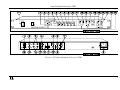
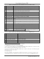
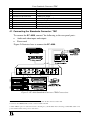
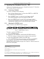
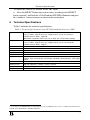
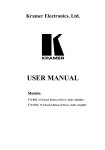
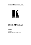
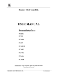
Kramer Electronics, Ltd.
USER MANUAL
Model:
FC-4000
Standards Converter / TBC
Contents
Contents
1
2
3
4
4.1
5
Introduction
Getting Started
Overview
Your Standards Converter / TBC
Connecting the Standards Converter / TBC
Operating Your Standards Converter / TBC
1
1
1
2
5
6
6
Technical Specifications
7
5.1.1
5.1.2
Converting a Standard
Adjusting the CONTROL Levels
6
6
Figures
Figure 1: FC-4000 Standards Converter / TBC
Figure 2: FC-4000 Standards Converter / TBC Connections
Figure 3: SELECT Button Sequence
3
5
6
Tables
Table 1: Front Panel FC-4000 Standards Converter / TBC Features
Table 2: Rear Panel FC-4000 Standards Converter / TBC Features
Table 3: Technical Specifications of the FC-4000 Standards Converter / TBC
4
4
7
i
Introduction
1
Introduction
Dedication by Kramer Electronics since 1981, to the development and
manufacture of high quality video/audio equipment, makes the Kramer line
an integral part of the finest production and presentation facilities in the
world. In recent years, Kramer has redesigned and upgraded most of the line,
making the best even better!
The Kramer line of professional video/audio electronics is one of the most
versatile and complete available, and is a true leader in terms of quality,
workmanship, price/performance ratio and innovation. In addition to our high
quality standards’ converters, we also offer excellent switchers and matrices,
encoders, decoders and transcoders, distribution amplifiers, remote
controllers, processors, interfaces and computer-related products.
Congratulations on purchasing your Kramer FC-4000 Standards Converter /
TBC.
This product is ideal for the following typical applications:
Studio standards conversion
Timebase correction, frame-store synchronization for production and
duplication
Studio color correction
The package includes the following items:
FC-4000 Standards Converter / TBC
Power cord
This user manual
Kramer concise product catalog/CD
2
Getting Started
We recommend that you:
Unpack the equipment carefully and save the original box and packaging
materials for possible future shipment
Review the contents of this user manual
3
Overview
The Kramer FC-4000 Standards Converter / TBC is a high quality standards
converter and Timebase corrector with full proc-amp facilities and a
1
Your Standards Converter / TBC
1
GENLOCK input (for frame synchronization).
In addition, the FC-4000:
Converts between all common standards: PAL (B, D, G, H, I, M, N); NTSC
(4.43, 3.58); and SECAM
Includes 2 sets2 of video inputs: 2 composite and 2 Y/C (s-Video), as well as
the corresponding audio inputs
Includes 3 different video output formats - composite, Y/C (s-Video) and
component video (Y, R-Y, B-Y), as well as an audio output
Is designed so that Y/C (s-Video) takes priority over the composite video
when both composite and Y/C (s-Video) are connected as inputs3
Has AGC4 functionality for processing low quality sub-standard signals
Is digitally synthesized, generating a standard color bar when no video signal
is available on the inputs
Includes a digital comb filter for input system decoding
May be used for frame synchronization5 (for example, enabling the mixing or
processing of video signals)
Includes full digital decoding and encoding with highly integrated digital
processing
To achieve the best performance:
Connect only good quality connection cables, thus avoiding interference,
deterioration in signal quality due to poor matching, and elevated noise levels
(often associated with low quality cables)
Avoid interference from neighboring electrical appliances that may adversely
influence signal quality
Position your Kramer FC-4000 in a location free from moisture and away
from excessive sunlight and dust
4
Your Standards Converter / TBC
Figure 1 illustrates the front and rear panels of the FC-4000. Tables 1 and 2
define the front and rear panels of the FC-4000, respectively.
1 The video input acts as a TBC and can GENLOCK to the sync of another video, therefore synchronizing the 2 asynchronous
video sources
2 Labeled INPUT A and INPUT B, respectively
3 If Y/C (s-Video) is not connected, the composite video will take effect
4 Automatic Gain Control
5 As they use the same sync, color subcarrier frequencies and the same phase
2
KRAMER ELECTRONICS, LTD.
Your Standards Converter / TBC
Figure 1: FC-4000 Standards Converter / TBC
3
Your Standards Converter / TBC
Table 1: Front Panel FC-4000 Standards Converter / TBC Features
#
1
2
3
4
Feature
POWER Switch
OUTPUT Button
INPUT Button
AUTO Button
5
6
7
8
9
10
11
NTSC 3.58 LED Label
NTSC 4.43 LED Label
PAL LED Label
PAL M LED Label
PAL N LED Label
SECAM LED Label
CONT
(CONTRAST) LED
12 BRIGHT
(BRIGHTNESS) LED
13 COLOR LED
14
15
16
17
18
19
HUE LED
SELECT Button
INPUT A LED
INPUT B LED
Input Selector Button
- Button
20 + Button
Function
Illuminated switch supplying power to the unit
1
Press to select the output standard, illuminating the appropriate LED
Press to select the input standard, illuminating the appropriate LED2
Toggles between automatically recognizing the input standard (illuminating the
2
appropriate LED ) and the manual selection mode
Defines the INPUT or OUTPUT NTSC 3.58 standard
Defines the INPUT or OUTPUT NTSC 4.43 standard
Defines the INPUT or OUTPUT PAL (BDGH) standard
Defines the INPUT or OUTPUT PAL M standard
Defines the INPUT or OUTPUT PAL N standard
Defines the INPUT or OUTPUT SECAM standard
3
Select the CONT LED via the SELECT button. Adjust using the + and –
buttons
Select the BRIGHT LED via the SELECT button. Adjust using the + and –
buttons
Select the COLOR LED4 via the SELECT button. Adjust using the + and –
buttons
5
Select the HUE LED via the SELECT button. Adjust using the + and – buttons
Press to select an H PHASE and V PHASE control
Illuminates when selecting INPUT A
Illuminates when selecting INPUT B
Press to select the input source, INPUT A or B
Press to decrease the control level Press the + and – buttons simultaneously
6
to reset the selected CONTROL to its
Press to increase the control level
default value
Table 2: Rear Panel FC-4000 Standards Converter / TBC Features
#
Feature
Function
1
2
3
4
5
6
7
8
INPUT A Y/C 4p Connector
INPUT A CV BNC Connector
INPUT A L and R RCA Connectors
GENLOCK IN BNC Connector
OUTPUT Y BNC Connector
OUTPUT B-Y BNC Connector
OUTPUT L and R RCA Connectors
Power Connector with Fuse
s-Video (Y/C) input
Composite video input
Audio input
GENLOCK source7
Component video output
Component video output
Audio output
230 VAC, 50/60 Hz (115 VAC U.S.A) 5 VA power inlet
1 A green OUTPUT LED is positioned below the appropriate LED label
2 A red INPUT LED is positioned above the appropriate LED label
3 Select both the CONT (CONTRAST) and the BRIGHT (BRIGHTNESS) LEDs (simultaneously) to adjust the horizontal
phase of the TBC input (against GENLOCK input) using the + and – buttons
4 Select both the COLOR and the HUE LEDs (simultaneously) to adjust the vertical phase of the TBC input (against
GENLOCK input) using the + and – buttons
5 For an NTSC input only
6 Reset all the CONTROLS to their default values by simultaneously pressing the + and – buttons for more than 3 seconds
7 The FC-4000 unit functions as a Standards Converter when no video source is connected to the GENLOCK IN connector
4
KRAMER ELECTRONICS, LTD.
Your Standards Converter / TBC
#
Feature
Function
9
10
11
12
13
14
15
16
OUTPUT R-Y BNC Connector
OUTPUT CV BNC Connector
OUTPUT Y/C 4p Connector
Term Hi-Z Switch
GENLOCK LOOP BNC Connector
INPUT B L and R RCA Connectors
INPUT B CV BNC Connector
INPUT B Y/C 4p Connector
Component video output
Composite video output
s-Video (Y/C) output
1
Controls loop termination
2
GENLOCK loop
Audio input
Composite video input
s-Video (Y/C) input
4.1 Connecting the Standards Converter / TBC
To connect the FC-4000, connect3 the following to the rear panel ports:
Audio and video inputs and outputs
Power cord
Figure 2 illustrates how to connect the FC-4000:
Figure 2: FC-4000 Standards Converter / TBC Connections
1 Push down to terminate the line with 75 Ohm. Push up when the line extends to another unit
2 Connect to the GENLOCK IN connector of the next unit in the line
3 Switch OFF the power on each device before connecting it to your FC-4000. After connecting your FC-4000, switch on its
power and then switch on the power on each device
5
Operating Your Standards Converter / TBC
5
Operating Your Standards Converter / TBC
Section 5.1.1 describes how to convert a Standard and section 5.1.2 describes
how to adjust specific Control levels.
5.1.1
Converting a Standard
To convert a Standard, do the following:
1.
Press the Input Selector button1 to select either INPUT A or INPUT B.
The appropriate LED illuminates2.
2.
Press the INPUT button3 to select the desired input standard4.
The red LED illuminates above the appropriate LED label.
3.
Press the OUTPUT button5 to select the desired output standard.
The green LED illuminates below the appropriate LED label and the
selected input standard converts to the selected output standard.
5.1.2
Adjusting the CONTROL Levels
Figure 3 illustrates the SELECT button sequence:
CONT
BRIGHT
COLOR
HUE
H PHASE
V PHASE
Figure 3: SELECT Button Sequence
To adjust a specific CONTROL level:
Press the SELECT button
The appropriate CONT, BRIGHT, COLOR and/or HUE LED illuminates
Press the + button or - button to increase or decrease the current level
To adjust the HORIZONTAL PHASE of the TBC input:
Press the SELECT button one or more times, according to the SELECT
button sequence6, until both the CONT (CONTRAST) and the BRIGHT
(BRIGHTNESS) LEDs illuminate and press the + button or - button to increase or
decrease the current phase
1 Item 18 in Figure 1
2 Item 16 or 17, respectively, in Figure 1
3 Item 3 in Figure 1
4 Or press the AUTO button to automatically recognize the input standard
5 Item 2 in Figure 1
6 For example, if the BRIGHT LED presently illuminates, press the SELECT button 3 times to simultaneously illuminate the
CONT (CONTRAST) and the BRIGHT (BRIGHTNESS) LEDs for HORIZONTAL PHASE
6
KRAMER ELECTRONICS, LTD.
Technical Specifications
To adjust the VERTICAL PHASE of the TBC input:
Press the SELECT button one or more times, according to the SELECT
button sequence1 until both the COLOR and the HUE LEDs illuminate and press
the + button or - button to increase or decrease the current phase
6
Technical Specifications
Table 3 includes the technical specifications:
Table 3: Technical Specifications of the FC-4000 Standards Converter / TBC
Inputs:
Outputs:
AGC:
Decoder:
Encoder:
Input Formats:
Output Formats:
Controls:
Dimensions:
Power Source:
Weight:
Accessories:
2 Composite Video, 1Vpp/75 ohms on BNCs
2 Y/C (s-Video), 1Vpp/75 ohms (Y), 0.3Vpp/75 ohms (C) on 4P connectors
2 Audio-stereo on RCAs, 1Vpp/10K
(When both Composite and Y/C exist on an input, the Y/C input takes priority)
1 Composite Video, 1Vpp/75 ohms on a BNC
1 Y/C (s-Video), 1Vpp/75 ohms (Y), 0.3Vpp/75 ohms (C) on a 4P connector
1 Audio-stereo on RCAs, 1Vpp/1K
Composite Video and (Y) input 0.5 Volts to 2 Volts with AGC acting on sync tip
Digital comb filter on input
Digitally synthesized; with color bar generator when video input is not detected
PAL B/D/G/H/I/M/N, NTSC 3.58, NTSC 4.43 and SECAM
PAL B/D/G/H/I/M/N, NTSC 3.58, NTSC 4.43 and SECAM
Continuous control of contrast, brightness, color saturation, hue (NTSC only), H and
V phase, input selector button, input/output (standards selector) buttons, auto (input)
button
19-inch (W), 7-inch (D) 1U (H) rack-mountable
230 VAC, 50/60 Hz, (115VAC, U.S.A.) 5 VA max
.7kg. (6 lbs.) approx.
Power cord
1 For example, if the BRIGHT LED presently illuminates, press the SELECT button 4 times to simultaneously illuminate the
COLOR and the HUE LEDs for VERTICAL PHASE
7
LIMITED WARRANTY
Kramer Electronics (hereafter Kramer) warrants this product free from defects in material and workmanship under the
following terms.
HOW LONG IS THE WARRANTY
Labor and parts are warranted for three years from the date of the first customer purchase.
WHO IS PROTECTED?
Only the first purchase customer may enforce this warranty.
WHAT IS COVERED AND WHAT IS NOT COVERED
Except as below, this warranty covers all defects in material or workmanship in this product. The following are not covered
by the warranty:
1.
2.
3.
Any product which is not distributed by Kramer, or which is not purchased from an authorized Kramer dealer. If you are
uncertain as to whether a dealer is authorized, please contact Kramer at one of the agents listed in the web site
www.kramerelectronics.com.
Any product, on which the serial number has been defaced, modified or removed.
Damage, deterioration or malfunction resulting from:
i)
Accident, misuse, abuse, neglect, fire, water, lightning or other acts of nature
ii)
Product modification, or failure to follow instructions supplied with the product
iii)
Repair or attempted repair by anyone not authorized by Kramer
iv)
Any shipment of the product (claims must be presented to the carrier)
v)
Removal or installation of the product
vi)
Any other cause, which does not relate to a product defect
vii)
Cartons, equipment enclosures, cables or accessories used in conjunction with the product
WHAT WE WILL PAY FOR AND WHAT WE WILL NOT PAY FOR
We will pay labor and material expenses for covered items. We will not pay for the following:
1.
2.
3.
Removal or installations charges.
Costs of initial technical adjustments (set-up), including adjustment of user controls or programming. These costs are the
responsibility of the Kramer dealer from whom the product was purchased.
Shipping charges.
HOW YOU CAN GET WARRANTY SERVICE
1.
2.
3.
To obtain service on you product, you must take or ship it prepaid to any authorized Kramer service center.
Whenever warranty service is required, the original dated invoice (or a copy) must be presented as proof of warranty coverage,
and should be included in any shipment of the product. Please also include in any mailing a contact name, company, address, and
a description of the problem(s).
For the name of the nearest Kramer authorized service center, consult your authorized dealer.
LIMITATION OF IMPLIED WARRANTIES
All implied warranties, including warranties of merchantability and fitness for a particular purpose, are limited in duration to
the length of this warranty.
EXCLUSION OF DAMAGES
The liability of Kramer for any effective products is limited to the repair or replacement of the product at our option. Kramer
shall not be liable for:
1.
2.
Damage to other property caused by defects in this product, damages based upon inconvenience, loss of use of the product, loss
of time, commercial loss; or:
Any other damages, whether incidental, consequential or otherwise. Some countries may not allow limitations on how long an
implied warranty lasts and/or do not allow the exclusion or limitation of incidental or consequential damages, so the above
limitations and exclusions may not apply to you.
This warranty gives you specific legal rights, and you may also have other rights, which vary from place to place.
NOTE: All products returned to Kramer for service must have prior approval. This may be obtained from your dealer.
This equipment has been tested to determine compliance with the requirements of:
EN-50081:
"Electromagnetic compatibility (EMC);
generic emission standard.
Part 1: Residential, commercial and light industry"
EN-50082:
"Electromagnetic compatibility (EMC) generic immunity standard.
Part 1: Residential, commercial and light industry environment".
CFR-47:
FCC Rules and Regulations:
Part 15: “Radio frequency devices
Subpart B – Unintentional radiators”
CAUTION!
Servicing the machines can only be done by an authorized Kramer technician. Any user who makes changes or modifications to
the unit without the expressed approval of the manufacturer will void user authority to operate the equipment.
Use the supplied DC power supply to feed power to the machine.
Please use recommended interconnection cables to connect the machine to other components.
8
KRAMER ELECTRONICS, LTD.
For the latest information on our products and a list of Kramer
distributors, visit our Web site: www.kramerelectronics.com.
Updates to this user manual may be found at
http://www.kramerelectronics.com/manuals.html.
We welcome your questions, comments and feedback.
Kramer Electronics, Ltd.
Web site: www.kramerelectronics.com
E-mail: [email protected]
P/N: 2900-004011 REV 2