1
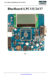
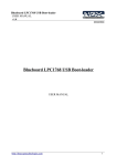
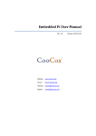
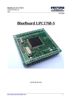
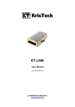
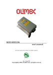
mX-BaseBoard with mX-LPC1343-S
USER MANUAL
v1.0
25/03/2011
mX-BaseBoard with mX-LPC1343-S
USER MANUAL
http://shop.ngxtechnologies.com
1
mX-BaseBoard with mX-LPC1343-S
USER MANUAL
v1.0
25/03/2011
Table of Contents
Introduction..........................................................................................................................................3
Features.................................................................................................................................................3
Getting Started......................................................................................................................................4
Requirement.........................................................................................................................................4
Hardware .........................................................................................................................................4
Software ..........................................................................................................................................4
Setup.....................................................................................................................................................4
Mounting the mX-LPC1343-S Board..............................................................................................4
Validating the mX-BaseBoard..............................................................................................................5
Led Blink.........................................................................................................................................6
LCD ................................................................................................................................................6
SD card............................................................................................................................................6
I2C...................................................................................................................................................6
USB..................................................................................................................................................7
UART ..............................................................................................................................................7
Buzzer..............................................................................................................................................7
Ext Int..............................................................................................................................................8
ADC.................................................................................................................................................8
PS/2..................................................................................................................................................8
ISP Programming..................................................................................................................................9
Compiling the Workspace...................................................................................................................11
Schematics.....................................................................................................................................12
Information.........................................................................................................................................13
Revision History......................................................................................................................13
Legal.........................................................................................................................................13
Disclaimers ..............................................................................................................................13
Trademarks ..............................................................................................................................13
http://shop.ngxtechnologies.com
2
mX-BaseBoard with mX-LPC1343-S
USER MANUAL
v1.0
25/03/2011
Introduction
mX-BaseBoard is a new addition to the BlueBoard line from NGX Technologies. This board
is intended to extend the functionality of the mX-LPC1343-S board. mx-LPC1343-S along with
pinout for LPC1343 includes a on board programmer/debugger which can be used with CoIDE.
mX-BaseBoard can be used to extend the features of the stamp by providing connectors and
interface to various peripherals of the stamp and provide power to the peripheral interface.
Features
•
2x16 with contrast control & back light
•
SD Card connector
•
USB
•
Power Jack
•
Power Switch
•
Reset Button
•
ISP Button
•
External interrupt Button
•
Buzzer
•
Audio Jack
•
PS/2
•
Serial Connector 0
•
Preset for ADC
•
On board EEPROM
http://shop.ngxtechnologies.com
3
mX-BaseBoard with mX-LPC1343-S
USER MANUAL
v1.0
25/03/2011
Getting Started
Before starting you would need the following things handy and ready. For compiling and
debugging programs refer to CoIDE User Guide. The CoIDE User Guide is for Nuvton, the same
procedure follows for NXP. The user needs to select the appropriate part number. Make sure that
you have read the CoIDE user guide carefully before you proceed further.
Requirement
The requirement is put in two sections.
Hardware
•
•
•
•
•
Power adapter – rating 7.5 V, 1 AMP
SD card
USB mini cable
Serial cable
PS/2 Keyboard
Software
•
•
•
PC with Windows OS
Use HyperTerminal as terminal software
mX-LPC1343-S CoIDE workspace from NGX Technologies
Setup
Mounting the mX-LPC1343-S Board
The mX-LPC1343-S board should be mounted on the mX-BaseBoard with a particular
alignment.
http://shop.ngxtechnologies.com
4
mX-BaseBoard with mX-LPC1343-S
USER MANUAL
v1.0
25/03/2011
Improper mounting of the mX-LPC1343-S board on mX-BaseBoard may damage the
mX-LPC1343-S board and / the mX-BaseBoard.
The GND pin on mX-LPC1343-S board should be aligned with the pin 1 of P9 female
header on BaseBoard. Refer to the marking as shown in the image above.
Validating the mX-BaseBoard
Download the workspace as .zip form here.
Download the Binary as .zip form here.
For flashing the Binary files please refer to CooCox CoFlash Quick Start with GUI.
1.You need to flash the mX-LPC1343-S board with the required firmware according
to the functionality.
2. The CooCox CoFlash Quick Start with GUI is for Nuvton, the same procedure
follows for NXP also.
Criteria for valid .bin file for LPC1343
The reserved ARM Cortex-M3 exception vector location 7 (offset 0x0000 001C in the
vector table) should contain the 2’s complement of the check-sum of table entries 0 through 6. This
causes the checksum of the first 8 table entries to be 0. The bootloader code checksums the first 8
locations in sector 0 of the flash. If the result is 0, then execution control is transferred to the user
code.
If the signature is not valid, the auto-baud routine synchronizes with the host via the serial
port (UART) or boots from the USB port (PIO0_3 is sampled HIGH).
http://shop.ngxtechnologies.com
5
mX-BaseBoard with mX-LPC1343-S
USER MANUAL
v1.0
25/03/2011
Led Blink
PORTS used → PORT0
PINS used → PIO0_7
Schematic net name → D2
A sample program to blink is provided, flash the 'mX-LPC1343_blinky.bin' file onto mXLPC1343-S and RESET. The LED (D2) should start blinking.
LCD
PORTS used → PORT2 for Data lines and PORT3 for Control lines.
PINS used → PIO2_6, PIO2_7, PIO2_8 and PIO2_9 for Data lines and PIO3_0, PIO3_1 and
PIO3_2 for Control lines
Schematic net name → LCD_D4, LCD_D5, LCD_D6, LCD_D7, LCD_EN, LCD_RW and
LCD_RS.
A sample program to LCD is provided, flash the 'mX-LPC1343_lcd.bin' file onto mX-LPC1343-S
and RESET. The LCD should display “NGX TECHNOLOGIES”.
SD card
PORTS used → PORT0 for MOSI,MISO and SSEL, PORT2 for SCK.
PINS used → PIO0_9,PIO0_8,PIO2_11 and PIO0_2.
Schematic net name → MOSI, MISO, SSEL and SCK.
A sample program to SD-card is provided, flash the 'mX-LPC1343_sdcard.bin' file onto mXLPC1343-S, insert a SD card and RESET.
On the LCD it should display “SD card - PASS”.
Remove the card and RESET, on the LCD should display “SD card - FAIL”.
I2C
PORTS used → PORT0 for I2C-SDA and I2C-SCL.
PINS used → PIO0_5 and PIO0_4.
Schematic net name → I2C-SDA and I2C-SCL.
A sample program to I2C is provided, flash the 'mX-LPC1343_i2c.bin' file onto mX-LPC1343-S
and RESET. The LCD should displays “I2C - PASS”. Connected to the I2C lines is an EEPROM
device. The program writes and reads back a piece of data to test.
http://shop.ngxtechnologies.com
6
mX-BaseBoard with mX-LPC1343-S
USER MANUAL
v1.0
25/03/2011
USB
Schematic net name → USB_DM and USB_DP.
A sample program to USB is provided, flash the 'mX-LPC1343_usbhid.bin' file onto mXLPC1343-S and RESET, Connect a USB cable to connector J7 with PC. In the device manager in
Windows it should be “HID-compliant device” as shown below.
Press and hold the RESET on the mX-BaseBoard, In the device manager in Windows it should be
“HID-compliant device” as shown below.
UART
PORTS used → PORT1 for TXD and RXD.
PINS used → PIO1_7 and PIO1_6.
Schematic net name → TXD and RXD.
A sample program to UART is provided, flash the 'mX-LPC1343_uart.bin' file onto mXLPC1343-S and RESET, Connect the serial cable to J4 and PC serial port. Open a HyperTerminal
with 115200 baud, 8N1. The typed characters on the keyboard are echoed on the HyperTerminal.
Buzzer
PORTS used → PORT1 for BUZZER.
PINS used → PIO1_11.
Schematic net name → BUZZER.
A sample program to BUZZER is provided, flash the 'mX-LPC1343_buzzer.bin' file onto mXLPC1343-S and RESET,on the mX-BaseBoard a tone is heard from the buzzer. The jumper JP1
should be inserted.
http://shop.ngxtechnologies.com
7
mX-BaseBoard with mX-LPC1343-S
USER MANUAL
v1.0
25/03/2011
Ext Int
PORTS used → PORT0 for EXT_SW.
PINS used → PIO0_7.
Schematic net name → EXT_SW.
A sample program to BUZZER is provided, flash the 'mX-LPC1343_exint.bin' file onto mXLPC1343-S and RESET, on the mX-BaseBoard the BUZZER toggles between ON and OFF when
the button SW6 is pressed.
ADC
PORTS used → PORT1 for ADC.
PINS used → PIO1_4.
Schematic net name → ADC.
A sample program to ADC is provided, flash the 'mX-LPC1343_adc.bin' file onto mX-LPC1343-S
and RESET, vary the pot R14 on the mX-BaseBoard . The change in value is displayed on the LCD.
PS/2
PORTS used → PORT2 for PS2-DATA and PS2-CLK.
PINS used → PIO2_4 and PIO2_5.
Schematic net name → PS2-DATA and PS2-CLK.
A sample program to PS/2 is provided, flash the 'mX-LPC1343_ps2.bin' file onto mX-LPC1343-S
and RESET, connect a PS/2 keyboard to mX-BaseBoard. Type the keys on the keyboard and the
corresponding characters are displayed on the LCD.
http://shop.ngxtechnologies.com
8
mX-BaseBoard with mX-LPC1343-S
USER MANUAL
v1.0
25/03/2011
ISP Programming
Since the LPC1343 has the USB bootloader on the ROM, it is advisable and highly
recommended to use USB interface for programming. If during reset the ISP line is held low and a
USB cable is connected the LPC1343 enumerates as a mass storage device. All the user needs to do
is just drag-n-drop the .bin file in order to program the LPC1343.
ISP using USB interface
The mX-LPC1343-S board can be programmed using USB interface. Connect a USB cable
from the base board (J7) to the PC. On the base board press and hold SW5, then press reset switch
SW4. Release the reset switch SW4 and then release SW5. The device will be detected as a external
storage device.
A file named firmware.bin is already present in this drive. Just delete this firmware.bin and
copy a valid .bin file. The criteria for creating a valid .bin file as follows.
The checksum generated by CoIDE(GCC) is not correct and unless the checksum of the .bin
file is modified, the firmware will be rejected by the USB bootloader. There is a tool to fix the
checksum, To download the free tool click here. To fix the checksum, simply go into the commandline and go to the root folder where both the lpcrc.exe tool and your .bin file are located and Enter
the following command:
lpcrc mX-LPC1343_blinky.bin
http://shop.ngxtechnologies.com
9
mX-BaseBoard with mX-LPC1343-S
USER MANUAL
v1.0
25/03/2011
Reset the board and program should start executing.
ISP using UART interface
LPC1343 also supports ISP over UART. If during reset the ISP line is held low and a USB
cable is NOT connected, the LPC1343 enters into ISP over UART. A flashing tool like Flash
Magic can be used to program the LPC1343.
Unfortunately due to some unknown reason, ISP over UART using mx-lpc1343-S and
mx-baseboard does not seem to work reliably. We are investigating this issue and
should soon have a solution for this. But since the ISP over USB works fine, ISP over
UART not functioning should not be a major issue.
http://shop.ngxtechnologies.com
10
mX-BaseBoard with mX-LPC1343-S
USER MANUAL
v1.0
25/03/2011
Compiling the Workspace
Download the workspace from here and unzip it. Start the CoIDE and Click Project to open
a directory path where the work space is unzipped and open a blinky workspace.
In CoIDE click on the build(or press F7) to build the project.
After building the project initiate debug to download the program to the target. Press F5 to run the
program execution. This blinks the D2 on mX-LPC1343-S board.
http://shop.ngxtechnologies.com
11
mX-BaseBoard with mX-LPC1343-S
USER MANUAL
v1.0
25/03/2011
Schematics
mX BaseBoard
mX-LPC1343-S
http://shop.ngxtechnologies.com
12
mX-BaseBoard with mX-LPC1343-S
USER MANUAL
v1.0
25/03/2011
Information
Revision History
version: v1.0 author: Nagaraj. M. Baddi
Legal
NGX Technologies Pvt. Ltd. provides the enclosed product(s) under the following conditions:
This evaluation board/kit is intended for use for ENGINEERING DEVELOPMENT, DEMONSTRATION, EDUCATION OR
EVALUATION PURPOSES ONLY and is not considered by NGX Technologies Pvt. Ltd to be a finished end-product fit for general
consumer use. Persons handling the product(s) must have electronics training and observe good engineering practice standards. As
such, the goods being provided are not intended to be complete in terms of required design-, marketing-, and/or manufacturingrelated protective considerations, including product safety and environmental measures typically found in end products that
incorporate such semiconductor components or circuit boards. This evaluation board/kit does not fall within the scope of the
European Union directives regarding electromagnetic compatibility, restricted substances (RoHS), recycling (WEEE), FCC, CE or
UL and therefore may not meet the technical requirements of these directives or other related directives.
The user assumes all responsibility and liability for proper and safe handling of the goods. Further, the user indemnifies NGX
Technologies from all claims arising from the handling or use of the goods. Due to the open construction of the product, it is the
user’s responsibility to take any and all appropriate precautions with regard to electrostatic discharge.
EXCEPT TO THE EXTENT OF THE INDEMNITY SET FORTH ABOVE, NEITHER PARTY SHALL BE LIABLE TO THE
OTHER FOR ANY INDIRECT, SPECIAL, INCIDENTAL, OR CONSEQUENTIAL DAMAGES.
NGX Technologies currently deals with a variety of customers for products, and therefore our arrangement with the user is not
exclusive. NGX Technologies assumes no liability for applications assistance, customer product design, software performance, or
infringement of patents or services described herein.
Please read the User’s Guide and, specifically, the Warnings and Restrictions notice in the User’s Guide prior to handling the
product. This notice contains important safety information about temperatures and voltages.
No license is granted under any patent right or other intellectual property right of NGX Technologies covering or relating to any
machine, process, or combination in which such NGX Technologies products or services might be or are used.
Disclaimers
Information in this document is believed to be reliable and accurate. However, NGX Technologies does not give any representations
or warranties, expressed or implied, as to the completeness or accuracy of such information and shall have no liability for the
consequences of use of such information.
NGX Technologies reserves the right to make changes to information published in this document, at any time and without notice,
including without limitation specifications and product descriptions. This document replaces and supercedes all information supplied
prior to the publication hereof.
Trademarks
All referenced trademarks, product names, brands and service names are the property of their respective owners.
http://shop.ngxtechnologies.com
13