1
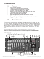
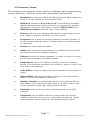
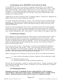
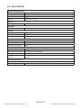
tm
Blizzard Lighting, LLC
www.blizzardlighting.com
Waukesha, WI USA
Copyright (c) 2014
TABLE OF CONTENTS
1. GETTING STARTED
1.1 What’s In The Box?
1.2 Getting It Out Of The Box
1.3 Powering Up!
1.4 Getting A Hold Of Us
3
3
3
3
3
IMPORTANT SAFETY INSTRUCTIONS
1.5 Instructions on Our Instructions
4
4
2. INTRODUCTION
2.1
Features 2.2
General Overview 2.3 Nifty, Spiffy Diagram (front)
2.4 Nifty, Spiffy Photo (back) 2.5 Common Terms
5
5
5
5
6
7
3. OPERATING INSTRUCTIONS
3.1
Setup 3.1.1 Setting Up The System 3.1.2 Fixture Addressing
3.1.3 The LED Display Screen
3.1.4 Resetting The System
3.2 Programming 3.2.1 Entering Programming Mode
3.3 Color/Scene Preset Programming Mode
3.3.1 Creating A New Color/Scene Preset
3.3.2 Color/Scene Preset Delete Mode
3.4 Chase Programming
3.4.1 Creating A New Chase
3.4.2 Inserting a Chase Step
3.4.3 Deleting a Chase Step
3.5 Playback
3.5.1 Manual Control Mode
3.5.2 Color/Scene Preset Mode
3.5.3 Chase Playback Mode
3.5.3.1 Auto Mode
3.5.3.2 Music Mode
3.5.3.2 Manual Mode
3.5.4 Playback Override
3.5.5.1 Strobe Setup
3.5.5.2 Strobe Playback
3.5.6 Blackout
3.6 USB Functions
3.6.1 Data Backup
3.6.2 Data Load
3.6.3 Firmware Update
3.7 Skywire Wireless DMX
3.7.1 Setting Up Skywire Wireless DMX
8
8
8
8
8
9
9
9
9
9
9
10
10
10
10
11
11
11
11
12
12
12
12
13
13
13
4. APPENDIX
4.1 A Quick Lesson On DMX
4.2 Keeping Your KONTROL 6 As Good As New
4.3 Returns (Gasp!) & Shipping Issues
4.5 TECH SPECS!
17
17
18
18
19
Page 2
KONTROL 6 Skywire Manual Rev. A 14
14
14
15
16
Copyright © 2014 Blizzard Lighting, LLC
1. GETTING STARTED
1.1 What’s In The Box?
•
•
•
•
1x KONTROL 6 Skywire™ DMX Controller
1x 9VDC, 300ma (minimum) AC/DC Adaptor
A Warranty Card & Warranty Info
This Lovely User Manual
1.2 Getting It Out Of The Box
We could tell just by lookin’ atcha. You’re a bit of a control freak, aren’t ya? Just kidding! CONGRATULATIONS! You’ve purchased a GREAT little DMX controller! Bravo!
Now that you’ve got your KONTROL 6 Skywire™, you should carefully unpack the box
and check the contents to ensure that all parts are present and in good condition. If
anything looks as if it has been damaged in transit, notify the shipper immediately and
keep the packing material for inspection. Again, please save the carton and all packing
materials. If a fixture must be returned to the factory, it is important that the fixture
be returned in the original factory box and packing.
1.3 Powering Up!
All fixtures must be powered directly off a switched circuit and cannot be run off a
rheostat (variable resistor) or dimmer circuit, even if the rheostat or dimmer
channel is used solely for a 0% to 100% switch.
AC Voltage Switch - Not all fixtures have a voltage select switch, so please verify that
the fixture you receive is suitable for your local power supply. See the label on the
fixture or refer to the fixture’s specifications chart for more information. A fixture’s
listed current rating is its average current draw under normal conditions. Check the
fixture or device carefully to make sure that if a voltage selection switch exists that it is
set to the correct line voltage you will use.
Warning! Verify that the voltage select switch on your unit matches the line
voltage applied. Damage to your fixture may result if the line voltage applied
does not match the voltage indicated on the voltage selector switch. All
fixtures must be connected to circuits with a suitable Ground (Earthing).
Getting A Hold Of Us
If something is wrong, just give us a call or send an email. We’ll be happy to
help, honest.
Blizzard Lighting
N16 W23390 Stoneridge Dr. Ste E
Waukesha, WI 53188 USA
www.blizzardlighting.com
414-395-8365
Email: [email protected]
Disclaimer: The information and specifications contained in this document are subject
to change without notice. Blizzard Lighting™ assumes no responsibility or liability
for any errors or omissions that may appear in this user manual. Blizzard Lighting™
reserves the right to update the existing document or to create a new document to
correct any errors or omissions at any time. You can download the latest version of this
document from www.blizzardlighting.com.
Author:
Date:
Last Edited:
Date:
W. Komassa
12/26/2012
J. Thomas
6/19/2014
Page 3
KONTROL 6 Skywire Manual Rev. A Copyright © 2014 Blizzard Lighting, LLC
IMPORTANT SAFETY INSTRUCTIONS
•
•
•
•
•
•
•
•
•
•
•
•
•
•
Please keep this User Guide for future use. If you sell the unit to someone
else, be sure that they also receive this User Guide.
ALWAYS make sure that you are connecting to the proper voltage, and that
the line voltage you are connecting to is not higher than that stated on the
decal or rear panel of the fixture.
This product is intended for indoor use only.
To prevent risk of fire or shock, do not expose fixture to rain or moisture.
Make sure there are no flammable materials close to the unit while operating.
The unit must be installed in a location with adequate ventilation, at least
20in (50cm) from adjacent surfaces. Be sure that no ventilation slots are
blocked.
ALWAYS disconnect from the power source before servicing or replacing
fuse and be sure to replace with same fuse size and type.
ALWAYS secure fixture using a safety chain. NEVER carry the fixture by its
head. Use its carrying handles.
DO NOT operate at ambient temperatures higher than 104°F (40°C).
In the event of a serious operating problem, stop using the unit immediately. NEVER try to repair the unit by yourself. Repairs carried out by
unskilled people can lead to damage or malfunction. Please contact the
nearest authorized technical assistance center. Always use the same type
spare parts.
NEVER connect the device to a dimmer pack.
Make sure the power cord is never crimped or damaged.
Never disconnect the power cord by pulling or tugging on the cord.
Avoid direct eye exposure to the light source while it is on.
Caution! There are no user serviceable parts inside the unit. Do not open
the housing or attempt any repairs yourself. In the unlikely event your unit
may require service, please contact Blizzard Lighting at [email protected].
1.5 Instructions on Our Instructions
We try to make these manuals easy to read and as fun as reading an instruction manual can be. Because there are buttons, switches, sliders and
knobs galore on most of our products, it makes sense to refer to things in
a consistent fashion. So, when you see text formatted in certain ways, it
should say to you “Hey! Look at me! I MEAN something, dammit!”
Special Text
What It Means
LED
Text displayed on the fixture’s LED control panel
<MENU>
Button <X> to be pressed
MENU --> SHMD
A sequence to be followed
000 <-> 255
A range of values
Page 4
KONTROL 6 Skywire Manual Rev. A Copyright © 2014 Blizzard Lighting, LLC
2. INTRODUCTION
2.1Features
•
•
•
•
•
•
•
•
•
•
•
•
DMX512/1990 Standard
2.4Ghz built-in wireless DMX transmitter
512 auto-assigning frequencies in 7 groups
18 preset scene/color banks, 9 per page
Record up to 18 chases with up to 200 scenes per chase
6 sliders for direct control of channels
Built-in microphone for music mode
Auto mode program controlled by fade time sliders
DMX out: 3-pin XLR
LED information display
Blackout function and instant strobe with variable speed fader
USB Backup/Restore of Data
2.2
General Overview
The controller is a universal intelligent lighting controller. It allows the control of 16 fixtures composed of 12 channels each and up to 18 programmable scenes. Eighteen chase banks can contain up to 200 steps composed of
saved scenes or manual inputs in any order. Programs can be triggered by
music, automatically or manually. All chases can be executed at the same
time.
On the surface you will find various programming tools such as 6
RGBAW+UV universal channel sliders, quick access fixture and scene buttons, and an LED display indicator for easier navigation of controls and
menu functions.
2.3 Nifty, Spiffy Diagram (front)
1
2
3
5
4
10
6
7
8
Page 5
KONTROL 6 Skywire Manual Rev. A 16
15
9
11
12
17
13
18
19
20
14
Copyright © 2014 Blizzard Lighting, LLC
Number
Button/Fader/Connection
Does...
1
Fixture Select Buttons
Fixture selection.
2
Fixture Indicator LEDs
Indicates the fixture(s) currently selected.
3
Scene Select Buttons / LEDs
Universal bump buttons representing scene location for
storage and selection.
4
Chase Select Buttons / LEDs
Universal bump buttons representing chase location for
storage and selection.
5
Channel Faders
Adjusts DMX values - Channel 1-5 may be adjusted after
pressing the respective fixture select button.
6
Edit/REC Button
Enters programming mode, records a step in a chase.
7
Insert/Tap Button
Inserts a step in a chase while in programming mode, or
allows tap control of chases in playback mode.
8
DEL/Clear Button
Deletes Scenes/Chases, clears current fader output.
9
Chase Time Fader
Sets the chase time in AUTO mode, 1=slowest, 10=fastest.
10
Fader Page Select Button
Toggles between control of the first or 2nd 5 DMX channels per fixture
11
Fade Time Fader
Sets the fade time in AUTO mode, 1=fastest, 10=slowest.
12
Strobe Speed Fader
Sets the speed of the strobe, 1=slowest, 10=fastest.
13
Blackout Button & LED
Stops all output from the controller.
14
Strobe Button / LED
Triggers the strobe function (momentary button)
15
Scene/Chase Page Select Buttons
Toggles between control/playback of Scene/Chase Page
A or B.
16
LED Display
Displays pertinent information about the current operation of the controller. See page 9 for more details.
17
LEFT/RIGHT Buttons
Selects the current bank, steps through chases in MANUAL mode, adjusts the sound sensitivity and the length of
time each chase runs when running multiple chases.
18
Run Mode Button & LEDs
Selects between AUTO/MUSIC/MANUAL modes and
displays current operating mode.
19
USB Disk Interface
For attachment of an optional USB disk drive, for backup/
restore of scenes/chases.
20
Mounting Holes
Allows you to securely fasten the controller to the surface
of your choice, also works nicely for holding pens,
pencils, and other small round things you always have
laying around.
21
Power Switch / Wireless (WD) Power Switch
Really? C’mon!
22
DC Power Input Connector
Plug in ONLY the included AC/DC adaptor here.
23
DMX Output Connector
3-pin DMX output - this is where all the magic happens.
24
Recessed Selector Button
To select the operating wireless channel group.
25
7-Color Status LED
Color coded status indicator LED light.
26
Antenna
1/2-wave Antenna.
2.4 Nifty, Spiffy Photo (back)
25
23
22
24
Page 6
KONTROL 6 Skywire Manual Rev. A 26
Copyright © 2014 Blizzard Lighting, LLC
2.5 Common Terms
The following are common terms used in intelligent light programming,
so pay attention! We’ll be using them throughout the manual.
•
Blackout is a state by where all lighting fixtures light output are
set to 0 or off, usually on a temporary basis.
•
DMX-512 stands for Digital MultipleX is an industry standard
digital communication protocol used in entertainment lighting
equipment. For more information read the DMX Primer and
DMX Control Mode Sections later in the manual.
•
Fixture refers to your lighting instrument or other device such
as a fogger or dimmer of which you can control.
•
Programs are a bunch of scenes stacked one after another. It
can be programmed as either a single scene or multiple scenes
in sequence.
•
Scenes are static lighting states.
•
Sliders are a delicious small burger or sandwich, but here they
are used in the same context as faders.
•
Chases can also be called programs. A chase consists of a number of scenes stacked one after another.
•
Stand Alone refers to a fixture’s ability to function independently of an external controller and usually in sync to music, due
to a built in microphone.
•
Fade Slider is used to adjust the time between scenes within a
chase.
•
Speed Slider affects the amount of time a scene will hold its
state. It is also considered a wait time.
•
Shutter/Strobe is a mechanical device in the lighting fixture
that allows you to block the lights path. It is often used to lessen the intensity of the light output and to strobe.
•
Patching refers to the process of assigning fixtures a DMX
channel.
•
Playbacks can be either scenes or chases that are directly
called to execution by the user. A playback can also be considered program memory that can be recalled during a show.
Page 7
KONTROL 6 Skywire Manual Rev. A Copyright © 2014 Blizzard Lighting, LLC
3. OPERATING INSTRUCTIONS
3.1Setup
3.1.1 Setting Up The System
Plug the AC to DC power supply to the system back panel and to the mains
outlet.
Plug in your DMX cable(s) to your intelligent lighting as described in the
fixtures respective manual. For a quick lesson on DMX see the DMX Primer section in the Appendix of this manual.
3.1.2 Fixture Addressing
The controller is programmed to control 12 channels of DMX per fixture,
therefore the fixtures you wish to control with the corresponding FIXTURE
buttons on the unit, must be spaced 12 channels apart.
DMX Start
Address
Fixt. #
Binary DIP Switch
Settings
(SET TO ON POSITION)
Fixt. #
DMX Start
Address
Binary DIP Switch
Settings
(SET TO ON POSITION)
1
1
1
9
97
1, 6, 7
2
13
1, 3, 4
10
109
1, 3, 4, 6, 7
3
25
1, 4, 5
11
121
1, 4, 5, 6, 7
4
37
1, 3, 6
12
133
1, 3, 8
5
49
1, 5, 6
13
145
1, 5, 8
6
61
1, 3, 4, 5, 6
14
157
1, 3, 4, 5, 8
7
73
1, 4, 7
15
169
1, 4, 6, 8
8
85
1, 3, 5, 7
16
181
1, 3, 5, 6, 8
Please refer to your individual fixture’s manual for detailed DMX addressing
instructions. The table above refers to a standard 9-DIP Switch binary configurable device.
3.1.3 The LED Display Screen
KONTROL 6 features a 4-position LED display which provides information
about the current mode, function and status of the controller. The messages
displayed on the screen are detailed here:
LED Display
Means...
S000-S200
When a Chase Preset is selected, displays the current chase scene being played
back. The display will step through chase steps based on the current output mode
(Auto/Music/Manual)
D000-D255
DMX value currently being assigned by the active fixture control fader.
F01.0 - F20.0
While holding down the <STROBE> button, displays the current strobe speed,
1-20 flashes per second
S0.10-S30.0
Chase scene time. From 0.1-30 seconds per step.
F0.00-F30.0
Chase fade time. From 0.1-30 seconds per step.
T0.10-T30.0
Tap tempo time, used in auto control mode.
M001-M100
Sound sensitivity, used in music control mode.
L001-L200
Loop Time. The time a chase will loop before moving to the next selected chase.
01Yc-10No
Displayed when the user selects channels to be used by the strobe function Yc=
Strobe Enabled (Yes), No=Strobe Disabled.
Page 8
KONTROL 6 Skywire Manual Rev. A Copyright © 2014 Blizzard Lighting, LLC
3.1.4 Resetting The System
WARNING: This will reset the controller to its factory defaults. ALL PROGRAMS AND SETTINGS WILL BE ERASED!
1. Turn the unit off.
2. Press and hold <EDIT/REC>, <RUN MODE> & <DEL/CLEAR>
3. Turn the unit on while you continue to hold <EDIT/REC>,<RUN
MODE> & <DEL/CLEAR>
4. The display will read rESr, then ot, then u2.0, then
point, release all 3 buttons.
5. The settings will be reset to factory defaults.
D000. At that
3.2 Programming
Regardless of whether you are programming a chase or scene, you must first
enter programming mode.
3.2.1 Entering Programming Mode
1.
2.
3.
4.
Press and hold <EDIT/REC> for 3 seconds.
The Program/REC LED indicator will blink, indicating programming is
active.
The LED indicators for any previously programmed scenes in the current bank and any previously programmed chases will blink.
Programming mode is now active.
3.3 Color/Scene Preset Programming Mode
This allows the user to create a preset color/scene which can be used to
override current fixture output and may also be used in chase programming.
3.3.1 Creating A New Color/Scene Preset
1.
2.
3.
4.
5.
6.
7.
8.
Enter programming mode as described in Section 3.2.1.
Using the <FIXTURE SELECTOR> button(s), select the fixtures to
include in the Color/Scene Preset.
Adjust the fixture(s) output using <CHANNEL FADERS 1-6> as
desired.
Press <EDIT/REC>.
Select the desired scene page using <SCENE PAGE>.
Press <SCENE 1-9>. All LEDs will flash quickly.
Repeat steps 1-6 to add additional presets if desired.
Hold <EDIT/REC> for 3 seconds to exit programming mode. The
LED indicator above the <EDIT/REC> button will extinguish.
3.3.2 Color/Scene Preset Delete Mode
This allows the user to delete a previously programmed preset color/scene.
1.
2.
3.
Enter programming mode as described in Section 3.2.1.
Select the desired scene bank using <LEFT/RIGHT>.
Hold <DEL/CLEAR>, then press the <SCENE 1-9> button you wish
to delete.
Page 9
KONTROL 6 Skywire Manual Rev. A Copyright © 2014 Blizzard Lighting, LLC
4.
5.
6.
All LEDs will flash 3 times, and the LED indicator for the selected
scene will now remain off. The scene has been deleted.
Repeat steps 2-4 to delete additional presets if desired.
Hold <EDIT/REC> for 3 seconds to exit programming mode. The
LED indicator above the <EDIT/REC> button will extinguish.
3.4 Chase Programming
A chase is a sequence of different scenes or steps which are called one after
another. KONTROL 6 can store up to 18 programs of 200 scenes each.
3.4.1 Creating A New Chase
1.
2.
3.
4.
5.
6.
7.
8.
9.
Enter programming mode as described in Section 3.2.1.
Using the <CHASE 1-9> button, select the chase you wish to program.
Using the <FIXTURE SELECTOR> button(s), select the fixtures to
include in the chase step.
Adjust the fixture(s) output using <CHANNEL FADERS 1-6> as desired, OR, to use a previously programmed scene/color preset:
Select the desired scene bank using <LEFT/RIGHT>.
Press <SCENE 1-9>.
Press <EDIT/REC>. All LEDs will blink 3 times to indicate the first
step has been stored successfully.
Repeat steps 2-6 to store additional steps if desired. Up to 200 steps
may be stored in each chase. If 200 steps have been stored in a
chase and the user attempts to store an additional step, the LED
display will read FULL.
Hold <EDIT/REC> for 3 seconds to exit programming mode. The
LED indicator above the <EDIT/REC> button will extinguish.
NOTE: After scene programming, press the <DEL/CLEAR> button to clear
any output, to avoid inadvertently overwriting a scene/color preset.
3.4.2 Inserting a Chase Step
1.
2.
3.
Enter programming mode as described in Section 3.2.1.
Using the <CHASE 1-9> button, select the chase you wish to modify.
Press the <INSERT/TAP> button. The LED indicator will illuminate
and the current step will display on the LED display. If there are no
steps in the chase, the display will read ST00.
4. Use the <LEFT/RIGHT> buttons to select the position for the inserted step.
5. Using the <FIXTURE SELECTOR> button(s), select the fixtures to
include in the chase step.
6. Adjust the fixture(s) output using <CHANNEL FADERS 1-6> as desired, OR, to use a previously programmed scene/color preset:
7. Select the desired scene bank using <LEFT/RIGHT>.
8. Press <SCENE 1-9>.
9. Press <EDIT/REC>. All LEDs will blink 3 times to indicate the first
step has been stored successfully. If no data has been stored, the
LED display will read NULL.
10. Repeat steps 2-9 to store additional steps if desired. Up to 32 steps
may be stored in each chase. If 32 steps have been stored in a chase
and the user attempts to store an additional step, the LED display will
Page 10
KONTROL 6 Skywire Manual Rev. A Copyright © 2014 Blizzard Lighting, LLC
read FULL.
11. Hold <EDIT/REC> for 3 seconds to exit programming mode. The
LED indicator above the <EDIT/REC> button will extinguish.
3.4.3 Deleting a Chase Step
1.
2.
3.
4.
5.
6.
7.
Enter programming mode as described in Section 3.2.1.
Using the <CHASE 1-9> button, select the chase you wish to modify.
Press the <INSERT/TAP> button. The LED indicator will illuminate
and the current step will display on the LED display. If there are no
steps in the chase, the display will read ST00.
Use the <LEFT/RIGHT> buttons to select the step to delete.
Press the <DEL/CLEAR> button. All LEDs will blink 3 times, indicating the delete has succeeded. The steps following the deleted step
will move up one step, and the chase will be one step shorter. If the
last step is deleted, the previous step will be displayed. If there are
no steps to delete, the LED display will read NULL.
Repeat steps 2-5 to delete additional steps as desired.
Hold <EDIT/REC> for 3 seconds to exit programming mode. The
LED indicator above the <EDIT/REC> button will extinguish.
3.5 Playback
The KONTROL 6 features three different playback modes: Manual Control
Mode, Scene/Color/Scene Preset Mode, and Chase Mode. Additionally, the
user may trigger step changes in chase mode in one of three ways: Automatically (Auto Chase Mode), Via audio signal detection (Music Chase Mode),
or Manually (Manual Chase Mode). We’ll look at all the options now.
3.5.1 Manual Control Mode
Allows the user to create a precise static color using KONTROL 6’s six control
faders.
1.
2.
3.
Ensure that BLACKOUT mode is not selected, IE that the LED indicator above the <BLACKOUT> button is not lit.
Using the <FIXTURE SELECTOR> button(s), select the fixtures to
be controlled.
Adjust the color output using <FADER 1-6> as desired.
3.5.2 Color/Scene Preset Mode
Allows the user to display one of up to 18 previously programmed color preset.
1.
2.
3.
Ensure that BLACKOUT mode is not selected, IE that the LED indicator above the <BLACKOUT> button is not lit.
Select the desired scene page using <SCENE PAGE A/B>.
Select the desired scene/color preset using <SCENE 1-9>.
3.5.3 Chase Playback Mode
Allows the user to display one or more of up to 18 previously programmed
chases in sequence.
Page 11
KONTROL 6 Skywire Manual Rev. A Copyright © 2014 Blizzard Lighting, LLC
1.
2.
3.
4.
5.
Ensure that BLACKOUT mode is not selected, IE that the LED indicator above the <BLACKOUT> button is not lit.
Select the desired scene page using <SCENE PAGE A/B>.
Press <CHASE 1-9> to run a chase directly. The corresponding LED
indicator will illuminate.
If you wish to run additional chases in sequence, select additional
chases to run by again pressing <CHASE 1-9>. The first chase selected will have its LED indicator lit. Subsequently selected chases
will have their LED indicators flash once per second.
Now, select the playback mode for the chase; Auto, Music or Manual.
3.5.3.1 Auto Mode
In auto mode, the chases will automatically move through their individual
steps based on the chase and fade times set using the <CHASE TIME> and
<FADE TIME> faders.
1.
2.
3.
4.
5.
6.
7.
8.
Follow the steps indicated in Section 3.5.3.
Press the <RUN MODE> button until the LED indicator for AUTO
mode is illuminated.
Using the <CHASE TIME> fader, adjust the time each step will be
displayed, between 0.1 and 30 seconds per step. The LED display will
indicate the current time.
Using the <FADE TIME> fader, adjust the time each step will be
displayed, between 0.1 and 30 seconds per step. The LED display will
indicate the current time.
Using the <LEFT/RIGHT> buttons, adjust the number of times to
loop each chase. This function is only applicable when 2 or more
chases are being run in sequence.
Finally, you may override the chase/fade times set using the faders
by using the <INSERT/TAP> button. Press the <INSERT/TAP>
button and the LED indicator will begin to blink.
Press the <INSERT/TAP> button again and the LED indicator will be
extinguished. The amount of time between successive button presses
will be the new chase time.
Adjusting the <CHASE TIME> or <FADE TIME> faders will override
this setting.
3.5.3.2 Music Mode
In music mode, the chases will automatically move through their individual
steps based on the beat detected via the internal microphone.
1.
2.
3.
Follow the steps indicated in Section 3.5.3.
Press the <RUN MODE> button until the LED indicator for MUSIC
mode is illuminated.
Using the <LEFT/RIGHT> buttons, adjust the sound sensitivity to
achieve optimal beat detection.
3.5.3.2 Manual Mode
In manual mode, the chases will move through their individually steps only
when triggered manually by the user.
1.
Follow the steps indicated in Section 3.5.3.
Page 12
KONTROL 6 Skywire Manual Rev. A Copyright © 2014 Blizzard Lighting, LLC
2.
3.
Press the <RUN MODE> button until the LED indicator for MANUAL
mode is illuminated.
Using the <LEFT/RIGHT> buttons, move through the steps in the
selected chase.
3.5.4 Playback Override
Allows the user to manually override the current output while in Color/Scene
Preset or Chase Playback Mode.
1.
2.
3.
4.
Ensure that BLACKOUT mode is not selected, IE that the LED indicator
above the <BLACKOUT> button is not lit.
Using the <FIXTURE SELECTOR> button(s), select the fixtures to be
controlled.
Adjust the color output using <FADER 1-6> as desired.
To return to Color/Scene Preset or Chase Playback Mode, press <DEL/
CLEAR>.
3.5.5.1 Strobe Setup
Allows the user to set the channel/channels which will be controlled by the
strobe function, for each fixture.
1.
2.
3.
4.
5.
6.
7.
8.
Enter programming mode as described in Section 3.2.1.
Press the <STROBE> button.
Using the <FIXTURE SELECTOR> button(s), select the fixtures to
setup.
Using the <LEFT/RIGHT> buttons, select the channel to adjust.
To enable the strobe function on the channel selected, press the
<EDIT/REC> button.
To disable the strobe function on the channel selected, press <DEL/
CLEAR>.
Repeat steps 2-7 to adjust additional channels/fixtures as desired.
Hold <EDIT/REC> for 3 seconds to exit programming mode. The
LED indicator above the <EDIT/REC> button will extinguish.
3.5.5.2 Strobe Playback
Allows the user to strobe the current playback. Note: Strobe operates even
when the <BLACKOUT> button is active.
1.
2.
3.
Press and hold the <STROBE> button. All currently selected/operating fixtures will strobe.
Using the <STROBE SPEED> fader, adjust the strobe speed, from 1
to 20 flashes per second.
Release the <STROBE> button, and strobing will stop.
3.5.6 Blackout
Allows the user to stop all fixture output immediately (except while strobing is
active).
1.
2.
Press the <BLACKOUT> button. All output will cease. The LED indicator will illuminate.
Press the <BLACKOUT> button again, and playback will resume.
Page 13
KONTROL 6 Skywire Manual Rev. A Copyright © 2014 Blizzard Lighting, LLC
3.6 USB Functions
KONTROL 6 is capable of saving/loading scene and chase data from USB
drives, using the USB jack on the unit’s front panel. During USB operation,
KONTROL 6’s LED display will show the following information, depending on
mode.
LED Display
Means...
SAvE
Indicates KONTROL 6 is currently in Data Backup/Save Mode.
LoAd
Indicates KONTROL 6 is currently in Data Load Mode.
UP--
Indicates KONTROL 6 is currently in Firmware Update Mode.
Ft01-Ft16
Displays the current file number to be written/loaded
ot
“OK,” indicates that the current file operation was successful.
FAIL
Indicates that the current file operation was unsuccessful. Try a different USB
device or program.
3.6.1 Data Backup
Allows the user to save scene and chase data to a USB Flash “Thumbdrive.”
1.
Press and hold the <RUN MODE> & <LEFT> buttons to enter Data
Backup Mode.
2.
3.
KONTROL 6’s LED display will show “SAvE.”
Use the <FIXTURE SELECTOR 1-16> buttons to select the file
name, “FILE1 - FILE16.”
Once backup is complete, KONTROL 6 will display the “OK” message
4.
(ot) as indicated above
3.6.2 Data Load
Allows the user to load scene and chase data from a USB Flash “Thumbdrive.”
1.
Press and hold the <RUN MODE> & <RIGHT> buttons to Enter
Data Load Mode.
2.
3.
KONTROL 6’s LED display will show “LoAd.”
Use the <FIXTURE SELECTOR 1-16> buttons to select the file
name, “FILE1 - FILE16.”
Once data load is complete, KONTROL 6 will display the “OK” mes-
4.
sage (ot) as indicated above
3.6.3 Firmware Update
Allows the user to upgrade KONTROL 6’s internal firmware from a USB Flash
“Thumbdrive.”
Page 14
KONTROL 6 Skywire Manual Rev. A Copyright © 2014 Blizzard Lighting, LLC
WARNING: AFTER STARTING FIRMWARE UPGRADE, DO NOT POWER DOWN
KONTROL 6 UNTIL THE UPGRADE FINISHES!!! UNPLUG ALL FIXTURES FROM
KONTROL 6 PRIOR TO PROCEEDING.
1.
2.
3.
4.
5.
Turn the unit off.
With the unit off, press and hold the <EDIT/REC> & <LEFT> buttons.
Continue to hold the button combination until KONTROL 6’s LED display shows “UP--.”
Release the button combination, then press any button to proceed
with the upgrade.
Once upgrade is complete, KONTROL 6 will display the “OK” message
(ot) as indicated above.
Page 15
KONTROL 6 Skywire Manual Rev. A Copyright © 2014 Blizzard Lighting, LLC
3.7.1 Setting Up Skywire™ Wireless DMX
1. Plug the receiver into the “DMX IN” connector of the fixture and verify it is
receiving power (the STATUS LED should illuminate.)
2. Turn on the “WD” wireless DMX power power switch on the back of the controller and verify it is receiving power (the STATUS LED should illuminate.)
3. Press the RECESSED SELECTOR BUTTON on the back of the controller
to select the operating channel group. (The system will store this setting for
future use)
The 7-Color Status LED will change color to indicate the current channel group:
·
·
·
·
·
·
·
GROUP
GROUP
GROUP
GROUP
GROUP
GROUP
GROUP
1:
2:
3:
4:
5:
6:
7:
RED
GREEN
YELLOW
BLUE
VIOLET
CYAN
WHITE
NOTE: “GROUP” number also
corresponds to the “GROUP”
setting on our LightCaster™
wireless DMX transceiver and
wiCICLE™ products.
4. Follow the same procedure on the receiver to select the channel group.
5. The LED will blink RED slowly until communication is established with the
receiver. The status LED on the receiver(s) will flash GREEN slowly until communication is established.
6. Once the clearest channel is auto-selected, the status LEDs will blink quickly
on both the transmitter and receiver. NOTE: The color of the LED DURING operation does not indicate channel group, instead it indicates whether the unit
is transmitting or receiving. That’s It!
Page 16
KONTROL 6 Skywire Manual Rev. A Copyright © 2014 Blizzard Lighting, LLC
4. APPENDIX
4.1 A Quick Lesson On DMX
DMX (aka DMX-512) was created in 1986 by the United States Institute for Theatre
Technology (USITT) as a standardized method for connecting lighting consoles to lighting dimmer modules. It was revised in 1990 and again in 2000 to allow more flexibility.
The Entertainment Services and Technology Association (ESTA) has since assumed
control over the DMX512 standard. It has also been approved and recognized for ANSI
standard classification.
DMX covers (and is an abbreviation for) Digital MultipleXed signals. It is the most common communications standard used by lighting and related stage equipment.
DMX provides up to 512 control “channels” per data link. Each of these channels was
originally intended to control lamp dimmer levels. You can think of it as 512 faders
on a lighting console, connected to 512 light bulbs. Each slider’s position is sent over
the data link as an 8-bit number having a value between 0 and 255. The value 0 corresponds to the light bulb being completely off while 255 corresponds to the light bulb
being fully on.
DMX data is transmitted at 250,000 bits per second using the RS-485 transmission
standard over two wires. As with microphone cables, a grounded cable shield is used to
prevent interference with other signals.
There are five pins on a DMX connector: a wire for ground (cable shield), two wires for
“Primary” communication which goes from a DMX source to a DMX receiver, and two
wires for a “Secondary” communication which goes from a DMX receiver back to a DMX
source. Generally, the “Secondary” channel is not used so data flows only from sources
to receivers. Hence, most of us are most familiar with DMX-512 as being employer over
typical 3-pin “mic cables,” although this does not conform to the defined standard.
DMX is connected using a daisy-chain configuration where the source connects to the
input of the first device, the output of the first device connects to the input of the next
device, and so on. The standard allows for up to 32 devices on a single DMX link.
Each receiving device typically has a means for setting the “starting channel number”
that it will respond to. For example, if two 6-channel fixtures are used, the first fixture
might be set to start at channel 1 so it would respond to DMX channels 1 through 6,
and the next fixture would be set to start at channel 7 so it would respond to channels
7 through 12.
The greatest strength of the DMX communications protocol is that it is very simple
and robust. It involves transmitting a reset condition (indicating the start of a new
“packet”), a start code, and up to 512 bytes of data. Data packets are transmitted
continuously. As soon as one packet is finished, another can begin with no delay if
desired (usually another follows within 1 ms). If nothing is changing (i.e. no lamp levels
change) the same data will be sent out over and over again. This is a great feature of
DMX -- if for some reason the data is not interpreted the first time around, it will be
re-sent shortly.
Not all 512 channels need to be output per packet, and in fact, it is very uncommon
to find all 512 used. The fewer channels are used, the higher the “refresh” rate. It is
possible to get DMX refreshes at around 1000 times per second if only 24 channels are
being transmitted. If all 512 channels are being transmitted, the refresh rate is around
44 times per second.
DMX has become the standard for lighting control. It is flexible, robust, and scalable,
and its ability to control everything from dimmer packs to moving lights to foggers to
lasers makes it an indispensable tool for any lighting designer or lighting performer.
Page 17
KONTROL 6 Skywire Manual Rev. A Copyright © 2014 Blizzard Lighting, LLC
4.2 Keeping Your KONTROL 6 As Good As New
The KONTROL 6 you’ve received is a rugged, tough piece of pro lighting
equipment, and as long as you take care of it, it will take care of you. That
said, like anything, you’ll need to take care of it if you want it to operate as
designed. You should absolutely keep the unit clean, especially if you are
using it in an environment with a lot of dust, fog, haze, wild animals, wild
teenagers or spilled drinks.
Cleaning the surface routinely with a suitable cleaner is useful for keeping the
faders clean and in good operating condition.
In transit, keep the controller in a case. You wouldn’t throw a prized guitar,
drumset, or other piece of expensive gear into a gear trailer without a case,
and similarly, you shouldn’t even think about doing it with your shiny new
lighting controller.
Common sense and taking care of your controller will be the single biggest
thing you can do to keep it running at peak performance and let you worry
about designing a great light show, putting on a great concert, or maximizing
your client’s satisfaction and “wow factor.” That’s what it’s all about, after all!
4.3 Returns (Gasp!)
We’ve taken a lot of precautions to make sure you never even have to worry
about sending a defective unit back, or sending a unit in for service. But,
like any complex piece of equipment designed and built by humans, once in
a while, something doesn’t go as planned. If you find yourself with a fixture
that isn’t behaving like a good little fixture should, you’ll need to obtain a
Return Authorization (RA).
Don’t worry, this is easy. Just send an e-mail to support@blizzardlighting.
com, and we’ll issue you an RA. Then, you’ll need to send the unit to us
using a trackable, pre-paid freight method. We suggest using USPS Priority
or UPS. Make sure you carefully pack the fixture for transit, and whenever
possible, use the original box & packing for shipping.
When returning your controller for service, be sure to include the following:
1.) Your contact information (Name, Address, Phone Number, Email
address).
2.) The RA# issued to you
3.) A brief description of the problem/symptoms.
We will, at our discretion, repair or replace the fixture. Please remember that
any shipping damage which occurs in transit to us is the customer’s responsibility, so pack it well!
4.4 Shipping Issues
Damage incurred in shipping is the responsibility of the shipper,
and must be reported to the carrier immediately upon receipt of the
items. Claims must be made within seven (7) days of receipt.
Page 18
KONTROL 6 Skywire Manual Rev. A Copyright © 2014 Blizzard Lighting, LLC
4.5 TECH SPECS!
Weight & Dimensions
Length
10.2 inches (255 mm)
Width
5.6 inches (142 mm)
Height
2.75 inches (69.5 mm)
Weight
3.25 lbs (1.5 kg)
Power
Operating Voltage
9-12 VDC, .3A (From included power supply)
Thermal
Max. Operating Temp.
104 degrees F (40 degrees C) ambient
Control
Protocol
USITT DMX-512
DMX Channels
192
Output
3-pin XLR Female
USB Data Format
USB Specification
1.0
Disk Format
FAT16 / FAT32 ONLY
Maximum Disk Size
4GB
Wireless Transmitter
Operating Band
2.4Ghz ISM
Max Operating Range
400 Meters (Line of Sight)
Frequency Groups
7
Max Transmission
Power
20dBm
Other Information
4 out of 5 dentists who chew gum also have a small ponytail and an earring.
Warranty
2-year limited warranty.
Page 19
KONTROL 6 Skywire Manual Rev. A Copyright © 2014 Blizzard Lighting, LLC
Page 20
KONTROL 6 Skywire Manual Rev. A Copyright © 2014 Blizzard Lighting, LLC