1
SYSTEM MANAGEMENT CENTER
USER MANUAL
VERSION 1.07
Copyright © 2013 Innovative Electronic Designs, LLC. All Rights Reserved
If this document is distributed with software that includes an end user agreement,this document, as well as the software described in it, is furnished under license and may be used or copied only in accordance with the terms of such license. Except as permitted by any such license,
no part of this document may be reproduced or transmitted in any form or by any means, electronic or mechanical, including photocopying, recording, storage in an information retrieval system, or otherwise, without the prior written permission of Innovative Electronic
Designs, LLC. Please note that the content in this guide is protected under copyright law even if it is not distributed with software that
includes an end user license agreement.
The content of this document is furnished for informational use only and is subject to change without notice. It should not be construed as
a commitment by Innovative Electronic Designs, LLC. Innovative Electronic Designs, LLC assumes no responsibility or liability for any errors or
inaccuracies that may appear in the informational content contained in this document.
Any reference to company names in examples are for demonstration purposes only and are not intended to refer to any actual organization
or an endorsement of any kind.
Innovative Electronic Designs, IED, GLOBALCOM, vACS, 500ACS, 500ACS Announcement Control System, CAS, Courtesy Announcement System, T-CAS, FAS, Flight Announcement System, IED On Call, IED On Call & Design, and LANcom are all registered trademarks or
trademarks of Innovative Electronic Designs, LLC in the United States and/or other countries.
CobraNet is a registered trade mark of Cirrus Logic in the United States and/or other countries.
Microsoft, Windows, Windows Vista, Windows 7, Windows Server, SQL Server, and Internet Explorer are all registered trademarks or trademarks of Microsoft Corporation in the United States and/or other countries.
Innovative Electronic Designs, LLC
9701 Taylorsville Road
Louisville, KY 40299
United States of America
www.iedaudio.com
Document Number: 1250C
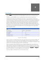
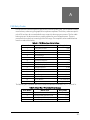
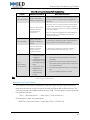
Publication History:
Revision
Publication Date
Comments
1.01
January 16, 2013
Various updates
1.02
April 10, 2013
Added DNA device
1.04
May 9, 2013
Updated DNA device
1.05
June 14, 2013
1.06
August 2, 2013
Updated for software release
1.07
December 10, 2013
Added new action types
Table of Contents
End User License Agreement
iii
Getting Started
1
3
Introduction
System Modes
System Definition Roadmap
Overview Tab
Announcement Activity
Mic & Zone Status
Current Faults
My Devices
Other Devices
6
8
11
11
13
15
16
18
Licensing
23
First Run Setup Wizard
27
Configuration
My System
My Controller
Remote Controllers
Devices
Internal CobraNet Audio Device
1100/1200 Message Server
T9032NS Titan Noise Sensor Device
External 8000 Device
MS528 Graphical Paging Station
MS524 4-Button Paging Station
Display Zone Controller
Display
Titan 9032LVIO Logic/Voltage I/O
Barionet50 Remote Logic/Relay I/O
1200 Logic Input/Relay Output
T9040NLR Noise, Logic & Relay Device
T9016RY / T9032RY Titan Relay Device
1502 Audio Outbox Device
1502 Audio Inbox Device
Annuncicom 100 Device
External Titan Zone
External Titan Source
1100TEL Telephone Interface
1100 Digital Audio Bridge
1522LR Logic/Relay Module
T9160 Digital Amplifier Frame
T9116 Zone Output Device
DNA7800 Series Amplifier
Generic CobraNet Device
SIP Telephone Interface
Action Types
Unused
ActivateEntryCode
CombinedLive
CombinedLive (Advanced)
CombinedPrerecorded
CombinedPrerecorded (Advanced)
Delayed
33
35
38
44
49
52
55
58
59
62
66
69
72
74
79
82
86
90
93
95
97
99
101
102
106
108
111
126
140
151
152
157
159
159
161
161
163
165
166
Delayed - Advanced Properties
DelayedFromAlternateSource
DelayedFromAlternateSource - Advanced Properties
Event
FaultSet
FaultClear
Live
Live - Advanced Properties
LiveFromAlternateSource
LiveFromAlternateSource - Advanced Properties
LiveOrDelayed
LiveOrDelayed - Advanced Properties
Monitor
Monitor - Advanced Properties
Mute
Mute - Advanced Properties
MuteAll
MuteAll - Advanced Properties
Prerecorded
Prerecorded - Advanced Properties
RecordTake
SMS
StopAnnc
TTS (Text-to-Speech)
TTS - Advanced Properties
VisualAlert
168
169
173
174
175
176
176
178
180
182
184
185
187
188
189
190
192
192
194
199
201
202
203
204
206
207
Announcement Classes
209
Zone Groups
213
User Groups
217
Mic Templates
Mic Template Editor
Mic Template Button Editor
Scroll Boxes
Mic Passwords
Scheduled Actions
Schedule
Events
Actions
Event Schedule
Visual Alerts and Wayfinding
Visual Alert Usage
221
222
224
226
229
231
232
239
240
242
243
245
Day / Night Schedule
247
SMS Lists
249
System Supervision
SNMP Endpoints
Fault Descriptions
Windows System Log
Print Configuration
Admin
251
252
253
254
259
261
Software Update
263
Backup / Restore
265
i
Table of Contents
Lifeline Control
269
Users
271
PDRP Languages
275
User Log
277
Debug Utilities
Reboot
File Management
Take Management
Command Shell
Error Counters
NetMon
Debug Messages
Appendices
289
FAS Entry Codes
291
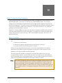
Basic Troubleshooting Guidelines
Basic Principles
Mic Station Control Line Failure (fault type 2)
Titan Amplifier Card Fault (fault type 4)
Titan Amp Frame Internal Card Fault (fault type 4)
Titan Amplifier Frame Environmental Fault (fault type 5)
Communication Channel Fault (fault type 9)
Monitor/Test Point Failure
VoIP User Interface
Scheduled BGM Level Change
Step 1: Configure Zones
Step 2: Configure Input Channel
Step 3: Use BGM Source
ii
279
279
280
282
284
285
285
288
293
293
294
294
295
296
296
297
301
303
304
304
305
End User License Agreement
End User License Agreement
SOFTWARE LICENSE AGREEMENT AND LIMITED WARRANTY
THIS IS A LEGAL AGREEMENT BETWEEN THE USER (“YOU”) AND INNOVATIVE ELECTRONIC DESIGNS (“IED”) RELATING TO SOFTWARE AND DOCUMENTATION (COLLECTIVELY “SOFTWARE”) PROVIDED WITH IED AUDIO COMPONENTS (“PRODUCTS”) OBTAINED FROM IED OR ITS AUTHORIZED CONTRACTORS. BY INSTALLING OR USING THE SOFTWARE, YOU ACKNOWLEDGE THAT YOU HAVE READ AND UNDERSTAND THIS
LICENSE AND AGREE TO BE BOUND BY ITS TERMS
License. In return for payment of the license fee, which is part of the price for the Products, and Your agreement to abide by the terms of this License, IED
grants to You a non-exclusive, non-transferable right to use the Software solely in connection with use of the Products. You may not copy the Software except
for archival or backup purposes. You acknowledge that IED is the sole owner of all rights in the Software (including copyrights, patents, trademarks and other
intellectual property rights), all copies, modifications, enhancements, and derivative works created therefrom, subject only to the license expressly granted
herein. This License does not provide You with ownership of the Software or a copy of it, but only a right of limited use.
Restrictions. You may not reverse engineer or assemble, decompile, decode or otherwise translate the Software. You shall not remove any copyright notice or
other proprietary or restrictive notice or legend contained or included in or on any Software or other material provided by IED, and You shall reproduce, copy
and include all such information on all copies made, including such copies for archivalor backup purposes. You shall use Your best efforts to assist IED in identifying any use, copying or disclosure of any portion of the Software by any of Your present or former personnel contrary to the terms of this License.
Termination. You may terminate this License at any time by returning the Software and all copies and extracts thereof to IED. You are not entitled to a refund
upon Your termination. In addition to other available remedies, IED may, at its option, terminate this License if You fail to pay any fees due or fail to carry out
any other obligation under this License. Upon IED's termination of this License, You are required to return or destroy and certify destruction, as requested by
IED, all copies of the Software in Your possession (whether modified or unmodified). Upon termination, all accrued fees shall he immediately due and payable.
Law; Scope of Agreement. This License shall be governed by the laws of the Commonwealth of Kentucky as it applies to contract made and performed in such
state without giving effect to conflict of law rules. You consent to jurisdiction and venue in the Commonwealth of Kentucky, the courts in Jefferson County, Kentucky, and the U.S. District Court for the Western District of Kentucky in any proceeding arising out of, or relating to, this License or Your use of the Software. If
any term of this License is declared void or unenforceable by any court, such declaration shall have no effect on the remaining terms hereof. No modification of
this License shall be binding on IED unless expressly accepted in writing by IED, This License is the entire agreement concerning the Software between You
and IED, and it supersedes any prior representation or understanding.
iii
End User License Agreement
This page has been intentionally left blank.
iv
Section 1
Getting Started
Introduction
3
Overview Tab
11
Licensing
23
First Run Setup Wizard
27
1
Getting Started
This page has been intentionally left blank.
2
1
Introduction
The System Management Center (SMC) is a browser-based configuration and control application
used to manage GLOBALCOM systems. The SMC is hosted on the hardware for the 1100ACS,
1200ACS, 1100MSG, 1200MSG, and 1100TEL. When used as part of a server-based vACS, it is
hosted on the server that is also hosting the vACS application. Because it is browser-based, all
functions and features available within the SMC can be accessed from any computer on the same
network as long as it has a compatible browser application installed.
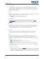
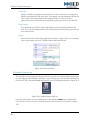
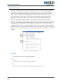
Since the application is hosted as a web page on the device, you simply need to know the IP address
of that device in order to access it from your web browser. Enter the IP address in the address bar of
the browser and you can launch the application. On many systems, a shortcut will be provided on
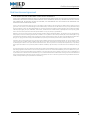
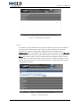
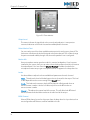
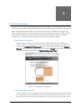
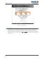
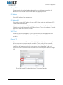
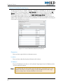
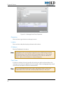
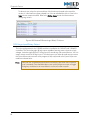
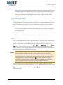
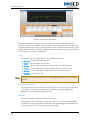
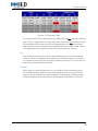
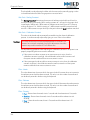
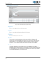
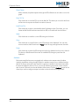
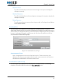
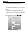
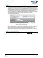
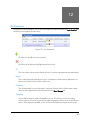
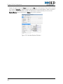
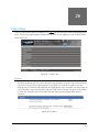
the desktop. Figure 1-1 shows the SMC main window.
Figure 1-1: System Management Center
The SMC interface is divided into three different sections. The Header and Status Bar provide various
status information and overall system interface options. The Configuration Options section of the
interface will change as needed based on the system parameters that you are editing.
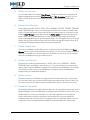
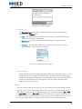
Header
This section of the SMC interface contains various status information as well as general
system commands accessible using icons or buttons as shown in Figure 1-2.
3
Chapter 1: Introduction
Figure 1-2: SMC Header
Fault Icon
This icon will only appear when a fault has been detected by the System Supervision subsystem. Click on it and you will be taken to the Current Faults section located on the
Overview Tab to view the current faults.
Save Icon
This icon will only appear when changes have been made to the configuration and have
not yet been saved. Click the icon to save the changes and send any new settings to
devices.
Help Icon
Click on this icon to open up the help system in a new browser window.
System Address and Version Information
This part of the header displays the current Ethernet address settings of the system. The
IP Address and Netmask settings reflect the address settings detected by the operating
system. The MAC Address is based on the Ethernet interface hardware and cannot be
changed. The System Version field displays the version of the SMC that is currently
installed on your system.
Note:
If the first three fields are ever just blank, check your network connection. If the
system is booted without network connectivity, then the operating system does not
provide any addressing information because the network service is not operating.
Once you have resolved the network issue, you will need to close and reopen the
SMC to get the correct information.
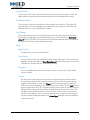
Login / Logout Button
The text on this button will change based on the current login status. If you are logged
in, it will display Logout and you can click it to log out of the system. If no one is logged
in, it will display Login. Click it and you will be prompted to enter a username and
password to log into the system.
4
Chapter 1: Introduction
When a user is logged in, the name of that account will appear immediately to the left of
the Login / Logout button. It will be blank if no user is currently logged in.
Configuration Options Tabs
The SMC is divided into three basic sections that are referred to as "tabs" in this
documentation. Access to each tab is based on permissions assigned to each individual
user account and they are categorized based on system usage and increasing degree of
complexity.
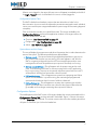
Click on the buttons to take you to the different tabs. The content available in the
Configuration Options section of the application window will change to reflect the
options available within that tab.
• Overview – See "Overview Tab" on page 11
• Configuration – See "Configuration" on page 33
• Admin – See "Admin" on page 261
System Name and Link Status
This text will display the system name and other information that is used to determine the
status of the system. The different possibilities are defined below.
• [System name] – The system name will typically be displayed here in gray text so
you will know which system you are viewing. If this text appears in red, then the
SMC is not getting a response from the vACS service application and you must
investigate the cause of this problem as your system is most likely not running.
• [System name] (Offline) – This will appear with the system name and in a red
color. This indicates that the SMC is communicating with the vACS application,
but it is not running. This may not necessarily indicate a system failure as a vACS
will be offline if a Lifeline has assumed its control functions.
• Lifeline Monitoring – This will appear on a system that is operating as a Lifeline
system. It indicates that it is up and running, but monitoring all programmed
systems and will take over their functions if a failure is detected.
• Lifeline System [x] – This will appear on a system that is operating as a Lifeline
system. It indicates that it has taken over control for the system indicated (as the
[x] variable) and is no longer monitoring other systems for failures.
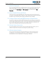
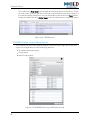
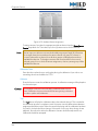
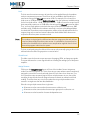
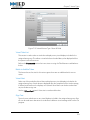
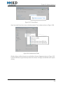
Configuration Options
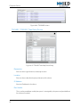
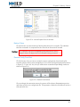
The middle portion of the SMC screen will change to display the content associated with the
Configuration Options Tab you have selected in the header. Figure 1-3 shows this section
when the Overview tab is selected. This section consists of a series of accordion panels that
will open or close when you click on the header bar.
5
Chapter 1: Introduction
Figure 1-3: Configuration Options Panels
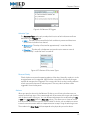
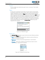
Status Bar
The bottom portion of the SMC screen contains a status bar that displays the current license
status and the current system operating mode. See "Licensing" on page 23 for more
information regarding the details of the items shown on the status bar.
Figure 1-4: Status Bar
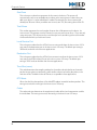
System Modes
The available configuration options available within the SMC will vary based on the hardware
that it is controlling and/or the way the system has been licensed. The four general categories of
different operational modes are outlined below.
Announcement Controller
In this mode, the vACS service is functioning as an announcement controller. It has the
ability to "own" system devices, thus you have access to adding, deleting, and
configuring devices from the SMC when operating in this mode. The majority of this
documentation is dedicated to devices operating in this mode as they have the most
configuration options available.
1100MSG / 1200MSG
This mode is used for the message server devices. In this case, the device will be "owned"
by an Announcement Controller and the parent device will manage the configuration of
the device. Since the parent device will do the configuration, the options available on a
device operating in this mode are very limited. The Configuration tab is not available
and you will find that most of the items on the Overview tab provide very little
information as they are managed on the vACS device. The Admin tab is the only tab of
use for this mode, but typically reserved for debugging only. You will need to log in with
an account with admin privileges to access that tab.
6
Chapter 1: Introduction
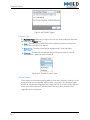
Figure 1-5: Message Server Options
Lifeline
This mode is used for Lifeline devices that monitor other announcement controllers in
the system and will assume their role if a failure is detected. Each announcement
controller in the system will push their configuration file to the Lifeline so the
Configuration tab is not available. You will find that most of the items on the Overview
tab provide very little information as the Lifeline doesn't actually own any devices. The
Admin tab is the only tab of use for this mode and has an additional Lifeline Control
configuration. You will need to log in with an account with admin privileges to access
that tab. See "Lifeline Control" on page 269 for details on configuring systems that are
monitored by the Lifeline.
Figure 1-6: Lifeline Options
7
Chapter 1: Introduction
1100TEL
This mode is used for the VoIP telephone interface device. In this case, the device will be
"owned" by an Announcement Controller and the parent device will manage the
configuration of the device. Since the parent device will do the configuration, the options
available on a device operating in this mode are very limited. The Configuration tab is
not available and you will find that most of the items on the Overview tab provide very
little information as they are managed on the vACS device. The Admin tab is the only tab
of use for this mode, but typically reserved for debugging only. You will need to log in
with an account with admin privileges to access that tab.
System Definition Roadmap
Defining a system is an iterative process that you can perform as required based on the needs of
a particular installation. The exact order and steps are really up to you, but there are certain
dependencies that must be taken into consideration. For example, you need to have
Announcement Classes defined before you start defining Actions as you must pick an
Announcement Class for many of the available action types. You can always go back and add
them as needed, but it helps to plan ahead to minimize the time you must spend switching
between screens.
This roadmap is here to give you a general starting point to guide you through configuring a
new system while describing the various dependencies involved.
1:
Define Users
You need to have at least three (3) users defined for your system with the different levels of
available access. Systems typically ship with three user accounts (user, installer, and admin).
You may use these three user accounts if desired, or you can change them. You can always
add more later as needed.
2:
Configure Local System
You need to configure the My Controller tab to define essential configuration options for
the local controller. If you will have a Lifeline system monitoring this controller, you will need
to come back here to add it once you have defined the Lifeline system in the Remote
Controllers tab. You need to skip the 1200LIR and VoIP configuration at this time. You will
come back and do this when you are ready to define Actions.
3:
Configure Remote Systems
Here you must tell the controller about all the other controllers in your system. You will need
these defined when it comes time to program Actions that go between controllers.
4:
Define Announcement Classes
You must have some Announcement Classes defined in order to define Actions for input
devices. The system will have some defaults already programmed, but you may want to add
more or edit the existing ones as needed. Again, you can always come back and add more
as you have a need.
8
Chapter 1: Introduction
5:
Define User Groups
You will need to define some basic User Groups in order to complete the configuration of
graphical paging stations and the Mic Passwords and Mic Templates sections. You can
skip this step if you do not have any graphical paging stations such as the 528 series
stations.
6:
Define Output Devices
Output devices include 1502AO, T9160, T9116, DNA68xx, T9016RY, T9032RY, T9040NLR
relays, T9032LVIO logic outputs, visual displays, and other devices that are used as system
outputs. Output devices own zone outputs and you must have zones in the system in order
to define Zone Groups and just about any of the Action Types will require zone groups or
zones in order to be completely defined. It is best to add all of your output devices so all
zones will be available when you go to program actions. You will need to return to the output
devices after you have configured input sources in order to assign BGM, adjust levels, and
configure and calibrate ambient analysis and system supervision.
7:
Define Zone Groups
Since you just added the output devices, now is a good time to go in and define the Zone
Groups that you think may be needed for your system. You can always come back here and
add them as needed, but it will save time if you can define as many as you can at this point
so they are available when you go to define actions.
8:
Define Input Devices
Input devices include microphone stations, 1502AI, Titan inputs, T9032LVIO, 1200LIR,
T9040NLR inputs, and ambient noise sensors, etc..) You may need to return to some input
devices again to perform additional configuration based on items added later. On example
will be that you need to return to an MS528 type microphone station to add a default
template after you have defined templates.
9:
Define Actions
This point is where you will define what happens with the inputs and outputs in the system.
You will need to have any input devices defined prior to programming actions for them. You
must have output devices and zone/zone maps defined in order to use them in an action.
10: Define Mic Templates
Mic templates determine the graphical button layout on the microphone stations that have a
graphical display. The buttons defined in the template need to be tied to actions, which must
be defined prior to creating the templates. You will need to go back to the microphone
station configuration to assign a template to each station after you have created the
templates in this step unless you are not using logins for the microphone station. If you are
using logins, then the template is determined by the passwords defined in the next step.
9
Chapter 1: Introduction
11: Define Mic Passwords
If you are not going to lock your microphone stations, then you can skip this step. If you will
require users to log into microphone stations, then you must define passwords for them.
You will need to have User Groups and Mic Templates defined before defining Mic
Passwords.
12: Define Scheduled Actions and Events
These do not link to any other defined actions, but do require any inputs and outputs that
you need to use already be defined. These are usually not defined until very late in the system
installation as you are working with the facility to determine what is needed.
13: Configure Output Levels and BGM Selections on Output Devices
Your specific situation may dictate that BGM settings and output levels are set as required
while you are installing the system. What is critical is that you perform final level adjustments
prior to calibrating the system supervision. Any changes made after that calibration will
require a new set be performed to record the new levels correctly.
14: Calibrate System Supervision
Once all loudspeaker lines have been fully connected and all output levels set, you can
calibrate the supervision sub-system and configure the periodic testing.
15: Calibrate Ambient Analysis
This is one of the last operations to be performed because it requires the system to be
installed and in a normal operating mode prior to calibration. Most of the operations
described above must be complete prior to attempting a calibration.
10
2
Overview Tab
The Overview tab provides access to view system activity and system health. This information is
provided even without logging into the application. A user that logs in will have the additional ability
to control levels and BGM selection for individual audio zones as well as the ability to terminate
active announcements if needed. Figure 2-1 shows the Overview tab selected. Each accordion tab
can be opened or closed by clicking on its title bar to reveal the information contained within each
tab.
Figure 2-1: Overview Tab
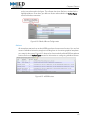
Announcement Activity
This is a list of any announcements that are either active or being held in queue on the local
announcement controller. This list provides some history of past announcements only from the
point where the System Management Center application was launched or from the last time the
Clear Announcements button was selected.
Figure 2-2: Announcement Activity
11
Chapter 2: Overview Tab
Kill
This button is only available when a user is logged in with a permission set of User or higher
and will only appear on announcements that are active. Click this button to kill the active
announcement.
Initiated
This is a date and time stamp of when the announcement was started.
Announcement ID
This is a system-assigned number to identify the announcement. When you move the mouse
pointer over a source as shown in Figure 2-3
Figure 2-3: Announcement ID
Status
This field indicates the current status of the announcement.
• Gone – Indicates that the announcement is finished and will not attempt any
further action.
• Active – Indicates that the announcement is currently routing audio channels
for either a live announcement or prerecorded message.
• Busy – Indicates that the announcement or message is being held in queue for
future playback. This can be either because it is waiting for zones to be freed due
to another active announcement or because it is waiting for additional playbacks
if multiple playbacks are used.
• Ready – This status sometimes appears briefly indicating that all resources have
been secured and the announcement is ready to play. This is immediately
followed by a change to Active status.
Type
This field displays the type of the announcement in the list.
12
Chapter 2: Overview Tab
• Prerecorded – This type of announcement indicates a playback of digitally
recorded audio from the internal sound card. When a Delayed message is
playing back, it becomes a Prerecorded type.
• Delayed – This type indicates that an announcement is in the process of being
recorded for future playback. When it plays back, it becomes a Prerecorded
announcement type.
• Live – This indicates that a live audio route is present between an input source
and one or more output zones.
Zones
This is a list of zones that are included in the announcement.
Source
This number corresponds to the Mic Number of the device that started the announcement.
Clear Announcements
Click this button to clear the announcement activity list. This only clears the list and will not
impact any announcements that are still active.
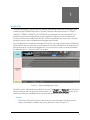
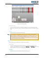
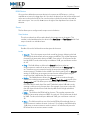
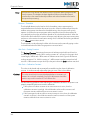
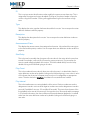
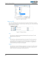
Mic & Zone Status
This tab provides a real-time graphical representation of announcement activity on the local
announcement controller. Input sources are shown on the left with a number that corresponds
to the Mic Number in the device setup. Each output zone is shown on the right with a number
corresponding to the zone number.
Figure 2-4: Mic & Zone Status
Active announcements are easily identified using colors. Output zones that are in use will
appear in a color that matches that of the originating input. Inputs that have communication
faults will be highlighted in red as can be seen in Figure 2-4 for mic number 9.
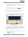
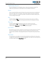
Zone Monitor
Click on any audio zone output to bring up the Zone Monitor window as shown in Figure 2-5
Any adjustments made from this window will be immediately sent to the device.
13
Chapter 2: Overview Tab
Figure 2-5: Zone Monitor
Output Level
This meter indicates the signal level at the currently selected point. A more precise
numerical indication of the level is located immediately below the meter.
Select Monitor Point
You must select one of the three available monitor points for each output channel. The
level meter will indicate the level of the signal at the point selected. This will also change
the point monitored audibly through a local monitor speaker if one is configured.
Monitor Mic
Some microphone station types have a built-in monitor loudspeaker. If you have one
installed in your system, then you can select it from this drop-down list and it will monitor
the selected point. You must have the Monitor Enabled checkbox checked in the
microphone station setup to get a microphone station to appear in the drop-down list.
Levels
Use these sliders to adjust the three available level parameters for each channel.
BGM – This adjusts the level of the background music channel for the output. This level
is also dependant on the current setting of the Overall level.
Duck – This level sets the amount that the BGM channel will be lowered when an
announcement is made. A level of –60 effectively will mute the BGM when an
announcement is made.
Overall – This adjusts the master level of the output. This will affect both BGM and
announcements and should be used to set the main level of the output.
BGM Channel
Select a BGM channel to use for this output from the drop-down list. Input devices that
are configured as a BGM source will be available in this list.
14
Chapter 2: Overview Tab
Mute
Click this checkbox to mute the output of the channel. This will mute all announcements
and BGM, regardless of priority.
OK
Click this button to close the window.
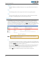
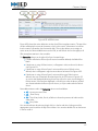
Current Faults
This list displays any current faults in the system. For information on historical logging of faults,
refer to the Windows System Log section of the documentation.
Figure 2-6: Current Faults
ID
This is an index number used to uniquely identify the fault.
Device
This field displays the system device that has reported the fault.
Description
This is a textual description of the fault. Devices report a Fault Type and Fault Number and
the System Management Center uses those two numbers to apply a description as defined in
the System Supervision section of the application.
Fault Type
This is the type number reported by the System Supervision module. The System Management
Center uses this, along with the Fault Number, to apply a description as defined in the
System Supervision section of the application.
Fault Number
This is the fault number reported by the System Supervision module. The System
Management Center uses this, along with the Fault Type, to apply a description as defined
in the System Supervision section of the application.
15
Chapter 2: Overview Tab
Optional
This field will display any additional information, if any, reported by the System Supervision
module.
First
This field displays a date and time stamp of when the fault was originally reported.
Last
As long as a fault condition exists, the System Supervision module will continue to collect
fault reports. This field displays the most recent fault report received.
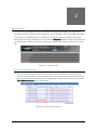
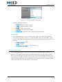
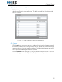
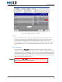
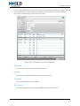
My Devices
This tab displays a list of all devices that are configured in the controller. It also indicates an
overview of device status. If the device is highlighted in red as shown in Figure 2-7, then the
device is not responding on the network. If a device is communicating, but reporting internal
faults, then you will see an exclamation point icon in the Faults column. You can hold the mouse
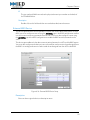
pointer over the icon to reveal a detailed list of the reported faults as shown in Figure 2-9.
Figure 2-7: My Devices
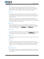
Note:
If you are logged in, then you can double-click on a device in the list to open the
device configuration for that device.
IP
This will display the IP address of the device. If the device is detected, but the IP address does
not match the configuration, then the device will be highlighted with a gold background and
you will see a Resolve button as shown in Figure 2-13.
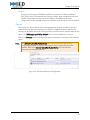
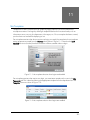
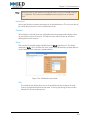
When you click the Resolve button, you will see a window like the one shown in Figure 2-8.
You can choose to set the IP address of the device to match that in the configuration, or
choose to change the configuration to match the IP address of the device.
Click the OK button to update the settings in the device and/or configuration.
16
Chapter 2: Overview Tab
Figure 2-8: Resolve IP Address
Description
This displays the text description of the device from the Description field in the device
configuration.
Faults
If an icon appears in this column, then the device is reporting faults. These faults will be listed
in the Current Faults list, but you can also display a list by hovering the mouse pointer over
the icon to reveal a pop-up window as shown in Figure 2-9
Figure 2-9: Device Fault Pop-up Window
Location
This displays the text description of the device from the Location field in the device
configuration.
Extra Info
This column displays additional information contained within the configuration of each
device. The information listed varies for each type of device, but it is easily readable as each
property is listed with the appropriate title.
17
Chapter 2: Overview Tab
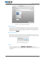
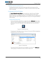
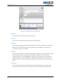
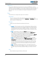
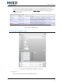
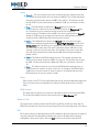
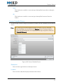
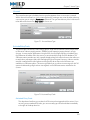
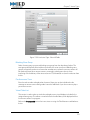
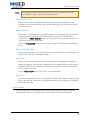
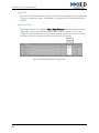
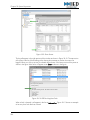
Other Devices
This tab is used to display any devices detected on the network that do not match any of the
configured devices. The system uses a background process, known as the Discovery Service,
that will detect and report any unknown devices on the network. This greatly simplifies the
process of adding and configuring new devices. You simply plug in the new device, wait for it to
appear in the list, and then add it to the system. There are three different configuration
scenarios.
Completely New Device
In this scenario, the system knows nothing of the newly detected device. You simply add
the new device and then configure it as needed.
Replacement Of Existing Device
In this scenario, you are adding a new device to the system that is replacing one that has
already been configured. You will choose which device in the configuration that the
newly discovered device will replace.
Adding a New Device Already Configured in Software
This scenario is similar to the previous, but in this case you have configured the device in
software prior to physically installing the hardware. The process is essentially the same.
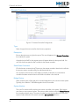
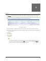
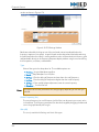
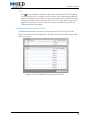
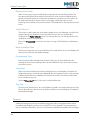
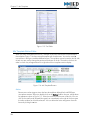
Figure 2-10 shows an MS528 microphone station detected in the Other Devices list. In this
case, the station has been used before because it already has information in the Description,
Location, and Extra Info fields. In this example, our goal is to replace the missing station named
Main Office with this new one.
Figure 2-10: Replacement Device Detected
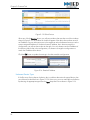
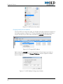
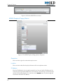
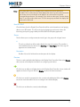
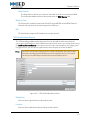
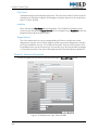
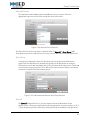
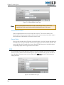
Double-click on the new device and you will be taken to the device configuration window as
shown in Figure 2-11. This is almost identical to the usual device configuration window used
when adding devices in the Devices tab. The difference is that you now have two new options at
the top of the window.
18
Chapter 2: Overview Tab
Figure 2-11: Device Configuration Window
Add as New Device
Select this option to add the discovered device as a completely new device in the system
configuration. It will use the discovered IP address of the device and automatically assign
any additionally required parameters and add it to the devices list. Once added, you can
configure it from the Devices tab.
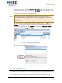
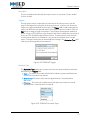
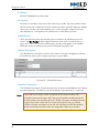
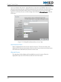
Replace Existing Device
Select this option to use the settings of a device that already appears in the devices list, but
apply them to this newly discovered device. Select the existing device configuration that you
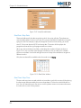
want to use from the drop-down list as shown in Figure 2-12.
Figure 2-12: Select Existing Device
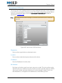
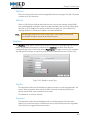
Resolve
This button may appear in either the My Devices or Other Devices tabs when the
discovered IP address is either not configured or does not match the IP address in the device
configuration.
19
Chapter 2: Overview Tab
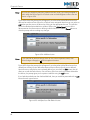
Figure 2-13: Other Devices
When you click the Resolve button, you will see a window that matches one of the windows
shown in Figure 2-14. The window on the left will appear if the device has not been set with
an IP address. You can either enter one in the top box or select the bottom button to use the
system-assigned IP address. If the device has an IP address, but it does not match the
configuration, you will see the window on the right. You can choose to set the IP address of
the device to match that in the configuration, or choose to change the configuration to
match the IP address of the device.
Click the OK button to update the settings in the device and/or configuration.
Figure 2-14: Resolve IP Address
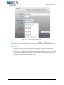
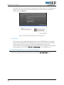
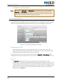
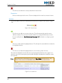
Unknown Device Type
If the Discovery Service detects the device, but is unable to determine the type of device, then
you will see a window like that in Figure 2-15. If this occurs, you must manually set the device
by selecting the appropriate type from the Type drop-down list as shown in Figure 2-16.
20
Chapter 2: Overview Tab
Figure 2-15: Device Configuration
Figure 2-16: Unknown Device Type Selection
21
This page has been intentionally left blank.
22
3
Licensing
The vACS has many different features that are enabled based on the license purchased. Below are
the various features that must be enabled through the license.
Number of Audio Zones
This licensing parameter determines how many audio output zones are allowed on the
system. The number of relay and sign zones do not count towards the total number of zones
in the license. Licensing options are available in 32, 64, 128, or unlimited audio zone
outputs.
Number of Frames
This licensing parameter determines the total number of Titan output frames that are
allowed in the system.
SMS (Short Message Service)
SMS allows the system to send text messages to mobile devices based on a variety of
triggers. This option requires a connection to the Internet and requires a subscription to the
SMS service.
VoIP
This determines if VoIP functionality is enabled on the controller. The 1100ACS-32,
1200ACS-32, 1100MSG, and 1200MSG devices support two (2) VoIP channels and will
have them enabled by default. For additional VoIP channels, you must use the 1100TEL that
supports up to eight (8) channels.
Text-to-Speech
Text-to-speech (TTS) is another software option that must be licensed separately from the
main system software. It is not part of the SMS/vACS license key, but I wanted to mention it
here since it is a system option that must be licensed separately.
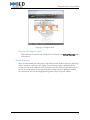
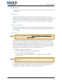
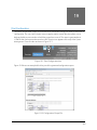
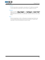
Figure 3-1 shows the main System Management Center (SMC) window. The bottom of the
window displays a status bar that provides you with various licensing information as well as the
current mode of the vACS application. The left portion of the bar indicates the capacities allowed
with the current license. The right portion of the bar indicates the operational mode of the
system.
23
Chapter 3: Licensing
System Modes
vACS
In this mode, the vACS service is functioning as an announcement controller.
MSG
In this mode, the controller is functioning as a message server and is seen as a device by
a vACS controller assigned as this device's owner.
Lifeline Monitoring
In this mode, the vACS service is functioning in Lifeline mode. It will monitor other vACS
controllers in the system and take over the functionality of any vACS controllers that fail.
Lifeline Active
This mode indicates that the controller has detected a failure with one of the vACS
controllers that it was monitoring. It has assumed control of the failed controller's
devices to maintain system functionality.
Transit
This mode indicates that the controller has been licensed for a transit application such
as a subway, light rail, bus, etc.
LANcom
This mode indicates that the controller is functioning as part of a LANcom SCS school
communications system.
Telephone Interface
This mode indicates that the controller is functioning as a VoIP telephone interface unit
such as the 1100TEL.
24
Chapter 3: Licensing
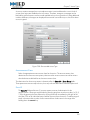
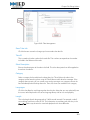
Figure 3-1: SMC Window
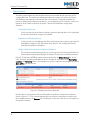
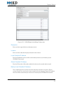
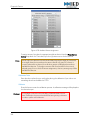
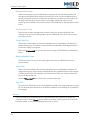
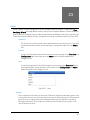
Figure 3-2 shows a detailed view of the system licensing information. This will show you what
capacity and functionality is supported with your current license. This is also where you will
launch the window that allows you to update your license for additional capacity.
Figure 3-2: License Details
Current Zones
This number reflects the actual number of audio zones that are configured in the system.
Licensed
This number reflects the total number of audio zones that are allowed with your current
license. The text will turn red if you attempt to configure more zones than the license allows.
If this text is red, any configured audio zones in excess of the licensed number will not
function.
Current Frames
This number reflects the actual number of Titan audio frames (T9160, T9116, etc) that are
configured in the system.
25
Chapter 3: Licensing
Licensed
This number reflects the total number of Titan frames that are allowed with your current
license. The text will turn red if you attempt to configure more frames than the license allows.
If this text is red, any configured frames in excess of the licensed number will not function.
SMS
This will read True if SMS (Short Message Service) is enabled on the controller. It will read
False if it is not enabled. SMS is used to send text messages to mobile devices.
VOIP
This will read True if VoIP service is enabled on the controller. It will read False if it is not
enabled.
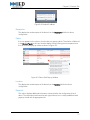
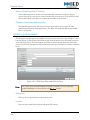
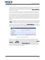
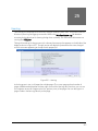
Update License
This text is actually a button. When clicked, it will take you to the license page as shown in
Figure 3-3. This page is used to update your current license. You must provide the systemspecific Challenge key to IED support personnel. They will give you the appropriate
Response key to use for your system. Once you have entered the Response key, click the
Submit License button to update the license.
Figure 3-3: Update License
26
4
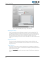
First Run Setup Wizard
The First Run Setup Wizard will appear when the System Management Console is started on a system
for the first time, or if the configuration file has been removed. The wizard will ask you to input some
basic system information and then it will generate a configuration file based on your inputs. This
greatly simplifies the process of configuring a new system and reduces the amount of data that you
must manually configure. You have the option of creating a configuration based on a default
template or you can load a configuration file that you created on another system.
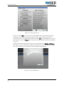
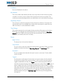
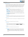
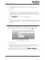
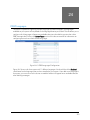
Load Default Configuration
Select this option and you can choose from a list of default configuration templates as
shown in Figure 4-1. Simply select the type of system you wish to configure from the list and
then click the Load Default Configuration button. This will then take you to the Configure
Devices screen as shown in Figure 4-4. You can click the Details button to see a description
of the item currently highlighted in the Default Configuration Files list.
Figure 4-1: Load Default Configuration
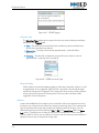
Load Configuration From File
Select this option if you want to load a system configuration from a file that has been created
on another system. This method is useful when you have multiple instances of the vACS in a
system and each one has a similar configuration. You can fully configure one system, and
27
Chapter 4: First Run Setup Wizard
then use that configuration as the starting point for the remaining systems. Once loaded,
you can go in and make the necessary changes.
This is also useful if you are replacing a vACS in a system. If you have maintained a backup
copy of the configuration, you can use it to configure the replacement unit.
Figure 4-2: Load Configuration From File
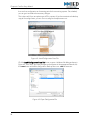
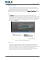
Click the Load Configuration From File button to open a Windows file dialog as shown in
Figure 4-3. From here, you simply navigate to the location of the appropriate file and click
the OPEN button to load the configuration. Backup files use a .VBK file extension.
Figure 4-3: Open Configuration File
28
Chapter 4: First Run Setup Wizard
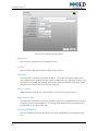
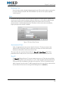
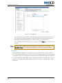
Configure Devices
On this page, you must enter some basic information about the system that you are
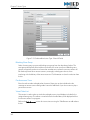
building. Figure 4-4 shows the device configuration page of the wizard.
Figure 4-4: Configure Devices
System Number
Each vACS controller in a system must have a unique number. You enter the number for
this controller in this field. You must reference this number when configuring other
controllers to communicate with this controller. The System Number is synonymous
with the term Group Number that is used for microphone station setup. You must
configure a microphone station with the Group Number of its parent controller.
System IP Address
By default, this field is populated with the current IP address obtained from the operating
system. If you change the address here, it will change the IP address of the controller.
System Netmask
This setting also defaults to the subnet mask setting obtained from the operating system.
Enter a subnet mask for the vACS that is appropriate for your network configuration if
the default is not sufficient. If you change the address here, it will change the subnet
mask of the controller.
Note:
The Internal CobraNet Audio Device has its own network port that must be
configured separately. The System Management Center cannot directly set this
address. Refer to the Internal CobraNet Audio Device documentation for
instructions on setting this address.
29
Chapter 4: First Run Setup Wizard
Inputs / Outputs / Core Devices
From here, you can enter the number of each type of device that you will have in the
system. These devices will be added to the system configuration and automatically be
assigned an IP address consistent with the settings of the System IP Address and
System Netmask.
Any devices that are not added here can be individually added to the system at any time
from the Devices tab of the configuration.
Save System Description & Define Users
Click this button to save the system information that you entered on this page and
continue on to the next page of the wizard.
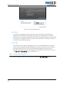
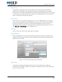
Configure Users
This page allows you to define the default users for the system. There are three (3) security
levels for users and you must define at least one user at each level in order to utilize the
system. More users for each level can be added later as needed.
Admin
A user with this permission level will have access to all system configuration options on
the Admin tab.
Installers
A user with this permission level will have edit access to everything on the Overview and
Configuration tabs. Some features on the Admin tab will not be available to this
category of user.
Users
A user with this permission level will have edit access to items on the Overview tab that
are needed for basic system operation. All functions on the Configuration and Admin
tabs are blocked for this category of user.
30
Chapter 4: First Run Setup Wizard
Figure 4-5: Configure Users
Save Users & Configure Devices
Click this button to save the user configuration and move to the Device Discovery page
of the wizard.
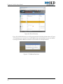
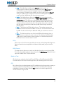
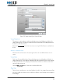
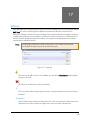
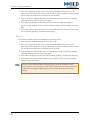
Device Discovery
When the wizard takes you to this page, it will attempt to find the devices that you previously
told the wizard you will have in your system. For some device types, it will automatically
configure the device IP address as well. If it finds devices that match the type of devices you
have in the configuration, but has previously been configured with a different IP address,
you will see them in the list and highlighted in gold as shown in Figure 4-6 below.
31
Chapter 4: First Run Setup Wizard
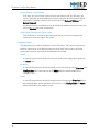
Figure 4-6: Device Discovery
If you click the Resolve button, you will be prompted with the dialog window shown in Figure
4-7. From here, you can elect to use the IP address that was discovered, or you can choose
to change the device address to match the one stored in the configuration file.
Figure 4-7: IP Address Resolution
32
Section 2
Configuration
My System
35
Devices
49
Action Types
157
Announcement Classes
209
Zone Groups
213
User Groups
217
Mic Templates
221
Mic Passwords
229
Scheduled Actions
231
Events
239
Visual Alerts and Wayfinding
243
Day / Night Schedule
247
SMS Lists
249
System Supervision
251
Print Configuration
259
33
Configuration
This page has been intentionally left blank.
34
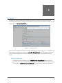
5
My System
This section is where you define certain parameters of the controller as well as define all other
controllers in the system. In order for this controller to communicate with another controller, it must
be defined in the Remote Controllers list.
Figure 5-1: My System Tab
There are three clickable text options located at the upper right corner of Figure 5-1. Clicking on one
of the options will take you to a page in the First Run Setup Wizard to quickly configure the system.
It is not recommended that you use these options if you have already configured devices in the
system.
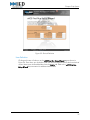
Default Configuration
Clicking on this text will take you to the vACS First Run Setup Wizard page as shown in
Figure 5-2. From here, you can select a default configuration from the list or load one from a
file. Refer to the vACS First Run Setup Wizard documentation for additional information.
35
Chapter 5: My System
Figure 5-2: Default Configuration
Device Definition
Clicking on this text will take you to the vACS First Run Setup Wizard page as shown in
Figure 5-3. From here, you can specify system address information and the number of each
device type in the system. Refer to the vACS First Run Setup Wizard documentation for
additional information.
Note:
36
The Internal CobraNet Audio Device has its own network port that must be
configured separately. The System Management Center cannot directly set this
address. Refer to the Internal CobraNet Audio Device documentation for
instructions on setting this address.
Chapter 5: My System
Figure 5-3: Device Definition
User Definition
Clicking on this text will take you to the vACS First Run Setup Wizard page as shown in
Figure 5-4. From here, you can define initial usernames and passwords for the three levels of
access. More users can be added later from the Admin tab. Refer to the vACS First Run
Setup Wizard documentation for additional information.
37
Chapter 5: My System
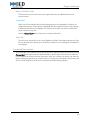
Figure 5-4: User Definition
My Controller
This represents the local controller to which you are currently connected. To edit the local
controller options, select it under the My Controller list. The right section of the window will
change to list the current configuration of the local controller. Any time you make changes to
the local controller, you must click either the OK or CANCEL buttons before attempting to select
anything else.
38
Chapter 5: My System
Figure 5-5: My Controller Configuration
Description
Enter a descriptive text string for the system. This text will appear at the top of the SMC
window to identify which controller page is currently accessed.
Send Reset Command
Click this button to restart the vACS service. Note that this will take the announcement
controller offline for a brief period of time.
Broadcast IP Address
This is the network address to use when broadcasting status messages such as
announcement reports.
External Titan Monitor Test Configuration
This box should be checked when you are using enhanced Titan (T9160) testing functionality
that requires the use of a separate configuration application. This is required when the Endof-Branch (EOB) testing devices are used in conjunction with at T9160 mainframe. When
enabled, the test configuration features are disabled in the T9160 device setup screens of
the SMC.
System Number
Each controller must have a unique system number. Enter the appropriate number here.
When you define this controller in another controllers Remote Controllers list, you will need
to properly reference this system number. This is also the Group Number used to configure
39
Chapter 5: My System
microphone stations to communicate with their parent controller.
Group Offset
This setting alters the method used for CobraNet bundle calculations. Leave this at the
default of 0 unless directed to do otherwise by factory support personnel.
System IP Address
By default, this field is populated with the current IP address obtained from the operating
system. If you change the address here, it will change the IP address of the controller.
Caution!
Changing the address here will require a system reboot if it is different
from the current settings.
System Netmask
This setting also defaults to the subnet mask setting obtained from the operating system. If
you change the address here, it will change the subnet mask of the controller.
Note:
The Internal CobraNet Audio Device has its own network port that must be
configured separately. The System Management Center cannot directly set this
address. Refer to the Internal CobraNet Audio Device documentation for
instructions on setting this address.
WCF Port
This sets the port that the application uses to communicate with other applications and
services. The default is 80 and it should not be changed unless it is required for a custom
installation.
AAS Manager Address
AAS stands for Automated Announcement System. If you have an installation that utilizes an
external announcement manager, such as the Flight Announcement System (FAS), then you
must enter the IP address of that server here. This allows the local controller to receive
announcement commands from that device.
Lifeline System
Select the Lifeline ACS (if used) that will be used to back up this controller from the dropdown list. Click the X icon to the right of the drop-down list to remove the selection. In order
for a system to appear in this list, you must have a system defined as a vACS Lifeline type in
the Remote Controllers list.
Kill Lifeline
This checkbox only applies when a vACS Lifeline is used to backup the local system. When
checked, the local controller will instruct the Lifeline controller to reset and relinquish its
control back to the local controller.
40
Chapter 5: My System
When not checked, you must go to the System Management Center page on the Lifeline
controller and manually relinquish control. You may also send a reset command using the
Send Reset Command button if you select the Lifeline controller in the Remote Controllers
list.
Use Multi 500R Protocol
Check this box if you are installing this controller in a system that has a 510/520ACS that
uses two IEDA500R cards for a 16-bus system instead of the standard 8-bus system.
Max RTP Connections
This property sets the maximum number of simultaneous incoming and outgoing RTP audio
streams that will be allowed by the controller. The maximum number that a single controller
is allowed to support is 8. Managing RTP connections utilizes a large amount of processor
resources, so a lower limit may be required on controllers that are also managing VoIP
telephone lines, text-to-speech, and multiple CobraNet channels for messaging. Note that
this limit only applies to announcements made to and from other controllers using the
routable RTP protocol. It does not impact announcements made using the CobraNet
protocol. A maximum limit of 2 is acceptable in most applications.
Voices
This section configures the Text-to-Speech voices that will be available for selection when
defining a TTS action type. This list is automatically populated with the languages that are
installed on your system.
Note:
TTS engines must be purchased and installed separately and are not included with
the base system software.
Description
This is a read-only description of the installed voice.
Language
Select the language for the voice. Only one voice can be defined for each language.
Thus, you cannot have multiple voices for the same language.
Gender
Select either a male for female voice from the drop-down list.
Speed
This value is used to adjust the speed at which the voice plays. A valid range is from –10
(very slow) to +10 (very fast). The default value is 0 and you can adjust it to meet your
needs. It is recommended that you adjust in increments of 1 until you are satisfied with
the results.
41
Chapter 5: My System
Volume
Select a numerical percentage (0 – 100) to set the volume of the voice. The system will
have default values that are unique to each voice. If the voice defaults to a value of 0,
then you must adjust it yourself. A value between 80 and 90 is a good starting point. This
field can be adjusted for each voice to evenly balance the installed voices with live and
prerecorded announcements.
Bitrate
This field allows you to select between bit rates of 16 or 8. 16 is recommended as it will
provide a higher quality speech rendering. Using a rate of 8 will result in smaller file sizes
and slightly faster rendering times, but at reduced quality.
Sample Rate
This field allows you to select between sample rates of 22000Hz and 16000Hz. 22000Hz
is recommended as it will produce a higher quality speech rendering. Using a sample
rate of 16000Hz will result in smaller file sizes and slightly faster rendering times, but at
reduced quality.
RTP Transmitters
RTP is used as the audio transport between vACS controllers that reside on different VLANs.
Each controller can support up to eight (8) simultaneous RTP connections. An RTP
Transmitter must be defined for each outgoing channel and have a unique multicast IP
address and port combination.
When you configure this controller as a remote controller on another vACS, you must use
the RTP Transmitter information from here to tell the other controller that this controller uses
these RTP Transmitters.
Click the + icon to add a new transmitter to the list. Click the X icon to delete the currently
selected item from the list.
ID
Each transmitter will be assigned its own unique ID number. This is a system-assigned
number and cannot be edited.
Audio Port
This is the RTP port number that will be used along with the multicast group IP address to
uniquely identify the audio channel. This number is automatically calculated by the
system, but can be changed to meet the installation network requirements.
The default port number is calculated using the following formula:
4000 + (1000 x {system number}) + {ID}
For example, transmitters 1 and 2 on system 1 would use ports 5001 and 5002.
Transmitters 1 and 2 on system 2 would use ports 6001 and 6002.
42
Chapter 5: My System
Audio IP
This is the multicast group IP address used by this controller. The default address is
239.192.0.x where x corresponds to the system number. When combined with the port
number, this provides a unique transmitter address. The address and/or port
configuration can be changed to meet the installation network requirements as needed.
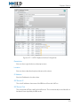
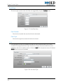
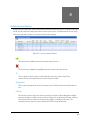
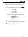
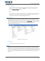
Devices
This section lists various devices that are contained within the local controller. Figure 5-6
shows the devices that are contained in the 1200ACS. Highlight the device and click the
settings icon located at the top of the list or double click on the item to open the editor for the
device. The1200 Logic Input/Relay Output device can be used to launch actions.
Refer to the Devices section of the documentation to learn how to configure each individual
device.
Note:
The Internal CobraNet Audio Device has its own network port that must be
configured separately. The System Management Center cannot directly set this
address. Refer to the Internal CobraNet Audio Device documentation for
instructions on setting this address.
Figure 5-6: My Controller Device Configuration
43
Chapter 5: My System
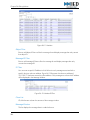
Remote Controllers
Figure 5-7: Remote Controller Configuration
Type
Select the type of remote controller that this entry represents.
Description
Enter a descriptive text string for the system. This text will appear in the Remote Controllers
list to identify the system.
A hyperlink to the SMC for the remote system will appear below the description field. You
can click this link to open the SMC window for the remote controller.
Send Reset Command
Click this button to restart the vACS service on the remote controller. Note that this will take
the announcement controller offline for a brief period of time.
You can also use this to reset a vACS Lifeline controller to relinquish its control after a
controller has been restored when the Kill Lifeline checkbox is not checked.
Bridge Device
Select the device that will be used as the network bridge device to access the remote system.
Typically, this will be the 1100DAB assigned to the local controller.
System Number
This is an ID number used by each announcement controller in the system. Each system
must have a unique system number. The system number is also used as the Group Number
for microphone station setup. The system number for a remote controller must match the
system number defined in the remote controller’s My Controller definition.
44
Chapter 5: My System
Group Offset
This setting alters the method used for CobraNet bundle calculations. Leave this at the
default of 0 unless directed to do otherwise by factory support personnel.
IP Address
This is the IP address of the remote system.
IP Address #2
This is used to identify the IP address of a second CPU when interfacing with a legacy ACS
that has redundant processors.
If the remote controller is a vACS Lifeline type, then you must enter the IP address of the
CobraNet sound card (if installed) in the Lifeline controller. Typically this address is 1 number
higher than the IP address of the controller.
WCF Port
This sets the port that the application uses to communicate with other applications and
services. The default is 80 and it should not be changed unless it is required for a custom
installation.
Remote TX
This number represents the ID number of the CobraNet bundle that the remote controller
will use to send announcements to other controllers. This is used by the local controller,
along with the System Number, to calculate the actual bundle number to receive audio
signals from the remote controller. For most systems, this number will be 1 and can be
found in the Internal CobraNet Audio Device setup on the remote system as shown in Figure
5-8.
Figure 5-8: Internal CobraNet Audio Device Transmitter Channels
45
Chapter 5: My System
Lifeline System
Select the Lifeline ACS (if used) that will be used to back up this controller from the dropdown list. Since one Lifeline ACS may backup multiple controllers, it is important for the local
controller to know which Lifeline ACS will backup each controller to prevent any conflicts.
Click the X icon to the right of the drop-down list to remove the selection. In order for a
system to appear in this list, you must have a system defined as a vACS Lifeline type in the
Remote Controllers list.
Push Takes
If this box is checked, the local controller will transfer new audio and visual takes to the
remote controller as they are added to the local controller. When used appropriately, this
will ensure that all controllers will have the same take files.
You must have this option checked when the remote controller is a Lifeline ACS.
Note:
When multiple playback devices are used, it may take up to one (1) minute for
recorded takes to be transferred to all other playback devices in the system.
Push All Takes
Click this button to immediately copy all audio and visual takes on the local controller to the
remote controller.
Caution!
This option requires the system to transfer very large amounts of data
over the network and will probably load the controller and network to
a point where it may no longer be able to process announcements.
Only use this option in a controlled situation where the system can be
taken offline while the copy is in progress.
Push Config
When checked, the configuration file of the local controller will be copied to the remote
controller each time the configuration is saved. When configuring a remote controller as a
Lifeline, you must check this box to ensure that the Lifeline controller will always have current
configuration data.
RTP Transmitter
This determines the method that the local controller will use to transmit and receive audio to
and from the remote controller. You must select either RTP or CobraNet from the dropdown list. When selecting RTP as the transport method, you must configure the RTP
Transmitters here to match the RTP Transmitter settings in the My Controller definition of
the other controller.
RTP Transmitters
Click the + icon to add a new transmitter to the list. Click the X icon to delete the currently
selected item from the list.
46
Chapter 5: My System
ID
Each transmitter will be assigned its own unique ID number. This is a system-assigned
number and cannot be edited.
Audio Port
This is the RTP port number that will be used along with the multicast group IP address to
uniquely identify the audio channel. This number is automatically calculated by the
system, but can be changed to meet the installation network requirements.
The default port number is calculated using the following formula:
4000 + (1000 x {system number}) + {ID}
For example, transmitters 1 and 2 on system 1 would use ports 5001 and 5002.
Transmitters 1 and 2 on system 2 would use ports 6001 and 6002.
Audio IP
This is the multicast group IP address used by this controller. The default address is
239.192.0.x where x corresponds to the system number. When combined with the port
number, this provides a unique transmitter address. The address and/or port
configuration can be changed to meet the installation network requirements as needed.
47
This page has been intentionally left blank.
48
6
Devices
Devices are the individual hardware components used in the system. Each must first be defined in
the Devices section of the software in order to be used. Once defined, devices can be used as
sources to launch actions, audio inputs available for routing, logic outputs to control other pieces of
hardware, or used as a destination for an announcement or message.
Figure 6-1: Devices
The specific details on configuring a device vary significantly with each type of device. They are
broken down and grouped into five (5) basic categories that share similar functions and properties.
• Aux I/O Devices
• Displays
• Controllers
• Mic Stations
• Amplifiers
Click this icon to add a new device to the system. A new window will appear as shown in
Figure 6-2. Select the device and click the OK button to continue. Clicking the Cancel
button will close the window without adding a new device.
49
Chapter 6: Devices
Figure 6-2: Add a New Device
After you click the OK button, the device will be added to the system and the properties
window for the new device will appear. Figure 6-3 shows the window for a 4-button
microphone station. Configure the properties and click OK to finish adding the new device
to the system. If you click Cancel, the window will close and the device will not be added to
the system.
To add multiple of the selected device type, enter the quantity in the Number of Devices
field. When used, the configuration window that appears will be for the last device added.
You will then need to go into each device and configure it appropriately.
Figure 6-3: New MS524 Device
50
Chapter 6: Devices
By default, only the most commonly used fields are shown when you edit a device’s
properties. Click the Show All Fields button to reveal all available properties. Once the
button has been used, the caption will change to Show Base Fields. You can click it again
to hide the less commonly used fields.
Note:
For simplicity, this documentation covers device setup with all fields shown.
Click this icon to edit the device properties for the currently selected device.
Click this icon to delete the currently selected device.
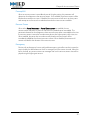
Actions
Certain device types have the ability to trigger actions. Microphone stations and logic input
devices are most commonly used to launch actions. Devices that can use actions will have
buttons that appear in the Actions column of the device list as shown in Figure 6-4. The
button will appear dimmed for those that cannot use actions.
Figure 6-4: Device Actions Button
The details for properties and actions are specific to the type of device. Refer to the device-specific
documentation in this section for details on each device type. For information on configuring
actions, please refer to the Action Types chapter of the documentation.
Apply Configuration Now
Figure 6-5: Apply Configuration Now Button
Some devices will have this button located at the upper left corner of the device properties
window. Click this button to immediately send changes to the device without closing the
window.
51
Chapter 6: Devices
Internal CobraNet Audio Device
This device is found in an 1100ACS, 1200ACS, 1100MSG, or 1200MSG unit. For the 1100ACS
and 1200ACS, it is configured from the My Controller tab as shown in Figure 5-6 of the My
System section. For the 1100MSG and 1200MSG devices, it is configured from the individual
device configuration page as shown in the 1100/1200 Message Server. This device is
responsible for playing back all prerecorded messages, delayed announcements, and text-tospeech (TTS) messages over the network using CobraNet. It is also responsible for recording the
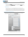
audio used for delayed announcements.
Figure 6-6: Internal CobraNet Audio Device Properties
Description
Enter text here to give the device a descriptive name.
Location
Enter text here to describe the physical location of the device.
IP Address
Enter the IP address for the device. It will usually be 1 digit higher than the IP address of the
unit that contains the device.
Note:
52
This address field only informs the System Management Center and the vACS of the
address of the device. You MUST configure the actual address of the card using a
separate configuration utility described later in this section.
Chapter 6: Devices
CobraNet Transmitters and Receivers
The CobraNet transmitters and receivers are automatically set by the system and the
defaults are sufficient for most applications. The ability to override the defaults is provided
here if it is required.
Configuring the ASI Card IP Address
The Internal CobraNet Audio Device is an internal plug-in card with its own IP address
information with its own configuration utility. The System Management Center cannot
directly configure the card's address information, so it is imperative that you configure the IP
address of the card using the supplied configuration utility if you ever change the IP address
of the controller.
Locating the ASIControl Utility
The Internal CobraNet Audio Device is configured using the ASIControl utility. Unless it
has been inadvertently deleted, there should be a shortcut located on the desktop that
will give you access to the Tools folder. Locate and double-click on the icon shown in
Figure 6-7.
Figure 6-7: Desktop Tools Icon
This will open the Tools folder as shown in Figure 6-8. Locate the ASIControl application
and double-click it to launch the utility.
Figure 6-8: Tools Folder
If you do not have the Tools shortcut on the desktop, you can launch the ASIControl
utility by going to the Windows Start menu as shown in Figure 6-9
53
Chapter 6: Devices
Figure 6-9: ASIControl in Start Menu
Changing the ASI Card IP Address
Once the ASIControl utility has started, you should see the device listed in the top part of
the window as shown in Figure 6-10. This list will display all CobraNet devices that are
on your network, but you will see the card listed with ASI5408 in the Name field.
Figure 6-10: Change ASI IP Address
Right click on the ASI5408 device in the list and you will see the pop-up window as
shown in Figure 6-10. Select the Change IP Address... option to open the window
shown in Figure 6-11.
Figure 6-11: ASI IP Address Configuration Window
54
Chapter 6: Devices
The card must be configured with a static IP address. Use of dynamic IP address is not
supported in the system. Select the Set static IP address radio button as shown in the
figure above and type in the IP address in the IP Address field. Once entered, click the
OK button to set the card to the new IP address. You can click the CANCEL button to
close the window without changing the address.
Note:
The system standard is to set the IP address of the internal CobraNet card to 1
number higher than the address of the controller's Ethernet port. If the controller
has an IP address of 10.2.128.10, then you would set the CobraNet card to
10.2.128.11.
There is one final critical step is required when configuring the Internal CobraNet Audio
Device. You must check to ensure that the card is not configured to auto-assign
CobraNet IP addresses. Go to the Options menu and select Configure Network
Interface and Auto-IP Assignment Range as shown in Figure 6-12
Figure 6-12: ASIControl Options Menu
This will open the window shown in Figure 6-13
Figure 6-13: Disable Dynamic CobraNet IP Address Assignment
1100/1200 Message Server
This device type is used to provide record and playback capacity for prerecorded messages, TTS
messages, and delayed announcements. The 1200MSG version adds eight (8) logic inputs and
eight (8) relays that can be used to launch messages or interface with external systems.
55
Chapter 6: Devices
Figure 6-14: Message Server Device Properties
Description
Enter text here to give the device a descriptive name.
Location
Enter text here to describe the physical location of the device.
IP Address
Enter the IP address for the device.
Note:
This IP address will automatically be assigned to the two VoIP interfaces and the
1200LIR device since they utilize the main network port on the unit. The Internal
CobraNet Audio Device uses its own network port, thus will have a different IP
address. Make sure this IP address is configured properly.
Push Takes
If this box is checked, the local controller will transfer new audio and visual takes to the
message server as they are added to the local controller. When used appropriately, this will
ensure that all controllers will have the same take files.
Note:
56
When multiple playback devices are used, it may take up to one (1) minute for
recorded takes to be transferred to all other playback devices in the system.
Chapter 6: Devices
Push All Takes
Click this button to immediately copy all audio and visual takes on the local controller to the
remote controller.
Caution!
This option requires the system to transfer very large amounts of data
over the network and will probably load the controller and network to
a point where it may no longer be able to process announcements.
Only use this option in a controlled situation where the system can be
taken offline while the copy is in progress.
TTS Enabled
Check this box if the message server has the Text-to-Speech (TTS) option installed. When
enabled, the message server will also create and play TTS messages.
Is 1200
Check this box and the 1200 Logic Input/Relay Output device will be shown in the Devices
list. This enables the logic inputs and relay outputs on the unit when it is a 1200MSG. If it is
an 1100MSG, this option should not be checked.
Note:
Actions for the 1200LIR inputs are configured by accessing the device actions from
the Devices section below.
Devices
This section lists various devices that are contained within the message server. Highlight the
device and click the settings icon located at the top of the list or double click on the item to
open the editor for the device.
Refer to the individual device type configuration in this section of the documentation to learn
how to configure each device.
57
Chapter 6: Devices
T9032NS Titan Noise Sensor Device
Figure 6-15: T9032NS Titan Noise Sensor Device Properties
Description
Enter text here to give the device a descriptive name.
Location
Enter text here to describe the physical location of the device.
IP Address
Enter the IP address for the device here.
Dev Handle
This is a software address used by the system. It is assigned by the system and provided here
for reference if needed.
Frame Number
This is a unique ID number used to identify the Titan frames used in the system. When yo
Noise Sensor Descriptions
This list is used to assign your own descriptive names for each noise sensor. This is the name
that will appear when you assign a sensor to a channel. It is recommended that you use a
name that references the either the name or zone number where the sensor is located.
58
Chapter 6: Devices
ID
This is a read-only field that matches the physical sensor input number on the back of
the T9040NLR device.
Description
Double-click on this field to edit the text used to describe/name the sensor.
External 8000 Device
This device type allows the vACS to operate in a system with an IED 8000 series system. In each
8000, you must configure a source using the EXTERNAL type in the 8000 configuration to allow
it to receive announcement commands from the vACS. You must also configure a zone using
the EXTERNAL type in the 8000 configuration to enable the 8000 to send commands to the
vACS.
This device type enables only the data communications between the vACS and the 8000 system.
You must also configure an audio input source that will be used to receive the audio signal from
the 8000. An analog audio zone is used to send the audio signal from the vACS to the 8000.
Figure 6-16: External 8000 Device Setup
Description
Enter text here to give the device a descriptive name.
59
Chapter 6: Devices
Mic Number
Each input on the device must have its own unique mic number. This is the number used to
identify the input as a usable source within the announcement controller. When you add the
device, each number is automatically defined. It can be changed if needed. Once it has
been defined here, it will appear as an available source when defining actions.
My Node ID
This is the number that is used to identify this controller to one or more 8000 systems. It must
be defined in the 8000 configuration in the channel field of the zone setup as shown in
Figure 6-17. In the example below, the Node ID is 4 and the Zone Type must be set to
EXTERNAL. This is a screenshot of the IED Navigator software used to configure 8000
systems.
Figure 6-17: 8000 Configuration
CoController IP Addresses
Each 8000 system that will be interacting with this controller must have their IP address
entered in this list.
Click this icon to add another controller IP address to the list.
Click this icon to modify the currently selected IP address.
Click this icon to delete the currently selected IP address from the list.
Zones
This list is used to define one or more zones in the local controller that will be used in local
zone groups with actions to trigger remote actions on the 8000. This configures the control
zones, so you must also include the appropriate audio zone in the zone group in order to get
live audio to the 8000.
Click this icon to add another zone to the list.
60
Chapter 6: Devices
Click this icon to delete the currently selected zone from the list.
ID
This ID is used to uniquely identify the zone to the controller. This number is
automatically assigned by the system based on the Start Zone number and the position
of the item in the list.
Description
Enter a textual description of the zone here.
Node ID
This is the Node ID of the 8000 that corresponds to this zone.
Entry Code
This is the entry code number that will be passed from the controller to the 8000 system
that matches the specified Node ID. This number must be defined in the Actions section
of the 8000 configuration. This number corresponds to the Button Number in the 8000
Action definition.
Start Zone
This is the zone number that represents the first zone that the local controller will use to
identify an 8000. The system will automatically use the next available zone number as the
starting zone number when you add a new device. It can be edited here if needed.
Total Zones
This number represents the total number of zones that will be allocated to communicate
with external 8000 systems. Each zone is numbered sequentially based on the start zone
entered in the Start Zone field. Each zone can be used to trigger one action on a single 8000
system.
Actions
The 8000 will send a message to the vACS controller that contains a Node ID number and
an Entry Code number. You must first define an action in the 8000 configuration that
includes the zone defined for this controller. There is a Miscellaneous Parameter field in the
8000 Action definition. The number you enter there is the same number that will be passed
to the vACS and used as the Entry Code to launch an action. You define an action here just
as you would for any other device type. Refer to the Action Types section for instructions on
defining individual actions.
For most announcements that originate from an 8000, you will use the
LiveFromAlternateSource action type.
61
Chapter 6: Devices
Figure 6-18: External 8000 Device Actions
MS528 Graphical Paging Station
Figure 6-19: MS528 Graphical Paging Station Properties
Description
Enter text here to give the station a descriptive name.
Location
Enter text here to describe the physical location of the microphone station.
IP Address
Enter the IP address for the microphone station here. You can find the IP address of the
station by pressing the 4 and 6 buttons simultaneously. This will bring up the information
window on the station display. You can then use the ENTER button to cycle through the
information and find the IP address.
62
Chapter 6: Devices
Mic Model
Select the appropriate version of the 528 used. Available selections are horizontal, vertical,
or horizontal with a gooseneck microphone.
User Group
Select the user groupassociated with the microphone station from the drop-down list. The
list of available groups is defined in the User Groups tab of the software. The name will be
displayed across the top of the microphone station display when the Lock Enabled box is
not checked. When checked, the name on the display is determined by the user as defined in
theMic Passwords tab. This field is optional unless you are using the microphone station in a
system with the Flight Announcement System (FAS) software option.
You can clear the selection in this field by clicking on the X icon to the right of the field.
Mic Template
Select the graphical button template to use for the microphone station. Templates are
defined in theMic Templates tab of the software. This template will be used only when the
Lock Enabled box is not checked. When that box is checked, the template used is
determined by the one assigned to the user in the Mic Passwords tab. If no template is
selected here, the station will use the one specified in the Default Template field in the My
System tab.
You can clear the selection in this field by clicking on the X icon to the right of the field.
Mic Local
Each microphone station can have up to four (4) Mic Local zone groups assigned. Mic Local
zone groups are a method of consistently assigning actions that have destinations that are
relative to the location of the microphone station. Let’s say you always want the push-to-talk
(PTT) button on the microphone station to do a live page to the same zone where the
microphone station is physically located. You would create a single action that has an entry
code of 0 (0 is for the PTT or ANNC buttons) with a zone group destination of Mic Local 1.
You would then assign the Mic Local 1 field in the microphone station setup to correspond
to a zone group programmed with the zone(s) local to that station. Each station can have a
different zone group assigned to the Mic Local 1 field. Since the action references that field
as the destination, it will always go to the local zone group.
This logic can apply to all of the available Mic Local zone group assignments. Mic Local 2
could be used for all immediately adjacent zones. Mic Local 3 could apply to all zones
within the local building. Using this feature allows you to create actions that function relative
to the location of the microphone station that is used to launch the action.
You can clear the selection in this field by clicking on the X icon to the right of the field.
Monitor Enabled
Check this box when using a microphone station with an attached monitor speaker such as
the IEDA528SRM.
63
Chapter 6: Devices
Test Mic Capsule
Check this box if the microphone station uses the 510HH handheld microphone. This
optional model of microphone has a built-in oscillator used to test the function of the
microphone element. Do not check this box if the microphone station has the standard
501HH handheld microphone.
Language
Select the default language for the microphone station from the drop-down list. This selects
the language used to display the various built-in prompts.
Click the X icon to the right of the field to clear the entry.
Lock Enabled
When checked, users are required to login using a password that has been configured in
the Mic Passwords tab. When enabled, the graphical template specified in the Mic
Template field is ignored and the template is determined by the user password.
Login Timeout
When microphone stations require user login, it will also automatically logout after the
interval specified in this field. This value is in seconds and defaults to 15 minutes (900
seconds) if left blank. The maximum value is 4200 seconds (70 minutes).
Mic Number
This is the number used to identify the microphone station within the announcement
controller. It must be a unique number within the local announcement controller.
Sidekick
Up to three (3) expansion stations can be used with a 528 microphone station when
equipped with an IEDA528E expansion board. Select the type of expansion station
connected to each port using the appropriate drop-down list. Available selections are as
follows:
• None – Expansion port is not used.
• FME – An IEDA520FME expansion station with PTT is used.
• Sidekick – An IEDA528SK Sidekick expansion station with 4-buttons and PTT is used.
The PTT on the expansion station will always launch the same action that is assigned to the
PTT of the parent station.
Sidekick Button Configuration
When you configure one of the types to Sidekick, you are presented with a new list like
the one shown in Figure 6-20. This allows you to define actions for each of the 4 buttons
available on the IEDA528SK expansion station. Select a button in the list and then click
64
Chapter 6: Devices
on the icon referenced in the figure. This will open the Action Definition window for the
highlighted button. From here, you define an action as described in the Action Types
section of the documentation.
Figure 6-20: Sidekick Button Configuration
Actions
All microphone stations that are the MS528 type share the same set of actions. You can limit
access to individual actions by simply not including them in the various graphical templates
you create for the system. Figure 6-21 shows a list of actions defined for MS528 microphone
stations. Refer to the Action Types section for information on configuring individual actions.
Figure 6-21: MS528 Actions
65
Chapter 6: Devices
MS524 4-Button Paging Station
Figure 6-22: MS524 4-Button Paging Station Properties
Description
Enter text here to give the station a descriptive name.
Location
Enter text here to describe the physical location of the microphone station.
IP Address
Enter the IP address for the microphone station here.
Mic Number
This is the number used to identify the microphone station within the announcement
controller. It must be a unique number within the local announcement controller.
Note:
The 524 microphone station uses DIP switches to configure the Group Number and
Mic Number on the hardware. They must be set to match the System Number and
Mic Number in the software.
Actions
Actions for 524 microphone stations are divided into Global and Device Specific actions.
Global actions will apply to all 524 microphone stations in the controller. This allows you to
quickly define actions that will be common to all 524 stations. Device Specific actions are
those that are only associated with an individual 524 microphone station. Each button on
the microphone station allows you to edit or define either the Global or Device Specific
actions. If you have a Device Specific action, then it will override the Global action on that
specific microphone station.
66
Chapter 6: Devices
Figure 6-23: MS524 Actions
Figure 6-23 shows the action definition window for a 524 microphone station. The top of the
window will display the name of the station, which in this case is "Information" to indicate
that the station is located at the information desk. This window allows you to assign an
action to each of the available buttons on the 524, or edit Default Actions that apply to all
524 microphone stations in the controller.
The Extra Info column on the right will tell you if several things.
• If neither a Default or Device Specific action have been defined, this field will be
blank.
• If the button is using a Default action, it will appear in italics as shown for button
A in Figure 6-23.
• If the button is using a Device Specific action and there is no Default action
defined, then it will appear in regular text as shown for button B in Figure 6-23.
• If the button is using a Device Specific action and there is a Default action
defined, then you will see both listed as shown for the PTT button in Figure 6-23.
An icon is also displayed indicating that a Device Specific action is overriding the
Default action. Since both are displayed, it will show you what the button will do if
you choose to delete the Device Specific action, or if you need to edit the Default
action.
Some abbreviations used in the Extra Info column are listed below:
• AC – Annnouncement Class
• ZG – Zone Group
• AV – This will say Audio, Visual, or Both to indicate the presence of audio and/or
video takes.
• EC – Entry Code
You can edit a button by selecting (single click) it in the list and then clicking one of the
appropriate icons located at the top of the window. You can also double-click on the button
in the list to edit it.
67
Chapter 6: Devices
Note:
Any time you attempt to add, edit, or delete a button action, you will be prompted to
select either the Device Specific or Default action with a dialog box similar to the one
shown in Figure 6-24.
Figure 6-24 shows the prompt that will appear if you selected to Add or Edit a button that
does not have either a Device Specific or Default action assigned. Note that you can select to
Add either type of action to the button by clicking on the appropriate button. This will take
you to the standard action definition window. Refer to the Action Types section of the
documentation for information on defining individual actions. Click the Cancel button to
close the prompt without making any changes.
Figure 6-24: Add New Action
Note:
If you add, edit or delete a Default action on any 524 microphone station, then
those changes will apply to all 524 microphone stations.
Figure 6-25 shows the prompt that will appear if you selected to Add or Edit a button that
already has a Default action defined but does not have a Device Specific action defined.
Notice that since a Default action is already defined, you now have an Edit button that will
allow you to edit the Default Action. Since a Device Specific action has not been defined for
this button, the prompt gives you the option to add one using the Add button.
If you had selected a button that has both defined, then you would be presented with an Edit
button for each type of action.
Figure 6-25: Add Specific or Edit Default Action
68
Chapter 6: Devices
Figure 6-26 shows the prompt that will appear if you first select a button and then click the
Delete icon. You will be prompted to delete either the Device Specific action for the button or
the Default action. If only one type is defined, then the Delete button will be grayed out as
you cannot delete something that has not been defined.
Note:
If you have a Device Specific action defined for a button and you wish to revert to the
Default action, simply delete the Device Specific action associated with that button.
Figure 6-26: Delete Action
Display Zone Controller
Use this device type to define a group of displays for visual paging. When you are using a text-tospeech (TTS) or prerecorded message, the display will show text that is synchronized to the
audible message. Each display will appear as an available zone in the Zone Group setup and
individual Action configuration.
This allows you to define a group of displays that will be addressed using a broadcast IP address.
For situations where you must individually configure each display, you must add a Display
device type for each individual display that is required. This would be the case if you must
configure displays to show other content when idle or if they are used for wayfinding.
69
Chapter 6: Devices
Figure 6-27: Display Zone Controller Setup
Description
Enter text here to give the device a descriptive name.
Location
Enter text here to describe the physical location of the device(s).
IP Address
Enter an appropriate broadcast IP address that will include all the displays. For example, an
address of 10.2.128.255 will includes all displays with an IP address in the range from
10.2.128.1 through 10.2.128.253.
Start Sign
This is the sign number that represents the first sign in the group. The sign number is treated
like the zone number for audio zones and included in the same list. The system will
automatically use the next available zone number as the starting zone number when you
add a new device. It can be edited here if needed. For example, you have a system that
already has 32 zones. When you add a new Display Zone Controller, the starting zone will
be 33.
Total Signs
This number represents the total number of signs that will be present in this group. Sign
zones do not count towards the total number of zones allowed by the software license.
70
Chapter 6: Devices
Note:
The system allows you to use display zone numbers that match audio zone
numbers. This is useful when you have displays that match up with audio zones and
you always want to include the visual display in any actions that include the
corresponding audio zone. For example, if you have an audio zone 10 and a display
zone 10, you only need to select zone 10 in the zone group and both the display and
audio zone will be used.
Non-IED DDC
Check this box when this Display Zone Controller will be used to broadcast visual paging
data to a non-IED system. This will cause the visual paging text to be sent without the
formatting and queuing tags used by the IED VisDID Visual Display application.
Zones
This list allows you to configure associate each sign in the group with a logical name.
#
This is the number that will be used to identify this sign in the system. This number is
calculated based on the values in the Start Sign and Total Signs fields. Each sign will
appear as an individual zone.
Description
Double-click on this field to edit a text descriptor for the display.
Devices
This list is used to add individual displays to the Display Zone Controller. Refer to the Display
device section of the help for information on configuring each device.
Click this icon to add a new Display device to the Display Zone Controller. A new window will
appear as shown in Figure 6-28 in the Display section of this documentation.
Click this icon to edit the properties for the currently selected display. Refer to the Display
section for more information on how to configure an individual display.
Click this icon to delete the currently selected display.
71
Chapter 6: Devices
Display
This device type is used to configure individual displays. From here, you can configure the
content that will be shown when the display is idle and you can specify which image to show for
a visual alert or wayfinding event.
Figure 6-28: Display Setup
Description
Enter text here to give the display a descriptive name.
Location
Enter text here to describe the physical location of the display.
IP Address
Enter the IP address for the display.
Screens
Click the + icon to add a new screen to the list. Click the X icon to delete the currently
highlighted screen from the list.
Sign
This ID number is used to identify the control processor (internal or external) that is
driving the sign. Some signs have built-in processors. This ID is used to identify the sign
to the system server for content display.
72
Chapter 6: Devices
Zone
This number corresponds to the actual zone number that will be used by the
announcement controller to send visual pages to the display.
Display
This ID number is used to identify the video output that drives this display. For a single
display, this ID will always be 1. For a processor that is driving multiple displays, this ID
will correspond to the monitor output as defined in the Windows setup. This ID is used to
identify the sign to the system server for content display.
Messages
This is a list of content that will be shown on the display when a visual page is not in
progress. A message in the list actually points to either a file or an HTML page that is
either stored on the local machine, or on a server. The display will cycle through the list
in the order based on the ID field.
Figure 6-29: Display Messages
To edit the messages, you will need to double-click on the Messages field in the table for
the display. This will open a new table that you can edit as shown in Figure 6-29. Use the
scroll bar at the bottom to access the individual message fields. The behavior of each
message is configured using the following fields in the table.
•
•
•
•
•
– Click the + icon to add a new message to the list. Click the X icon to
delete the currently highlighted message from the list.
URL – This can be either a link pointing to an HTML page or a media file.
Format – Enter HTML to identify this message as an HTML page. Enter FILE if the
link points to a media file. Valid media file types are .mpg, .mpeg, .wmv, .avi,
.mov, .mp4, .jpg, .jpeg, .gif, .bmp, .png, and .swf.
Count – This is the number of times this message will play before moving on to
the next message in the list.
Priority – This field is currently not implemented.
73
Chapter 6: Devices
• Hold Time – This is the amount of time that this message will stay on the screen
before moving on to the next message. This value is in 60ths of a second. A value
of 300 will hold the image on the display for 5 seconds.
• Refresh – This is the interval, in seconds, between refreshes of the HTML page.
This property has no function when the Format is set to FILE.
Visual Alerts
Visual Alerts are defined as described in the Visual Alerts and Wayfinding section.
There you will create individual alerts and upload the images that will be available for
use in each alert. You will see a list of the available alerts in this field. Select an image for
each alert from the drop-down list. Click the X icon to clear an image selection.
Owner Device
A Display device must be associated with an owner Display Zone Controller device. You can
either add a new display from the Devices list or from within the configuration window of an
individual Display Zone Controller. If you add a new Display directly from the Devices list,
then you will be prompted to add the new Display to an Owner Device when you exit the
properties window as shown in Figure 6-30. Select the appropriate device from the dropdown list and then press the OK button. The Display will now be available for editing from
within the configuration of the owner device.
Figure 6-30: Owner Device Prompt
Titan 9032LVIO Logic/Voltage I/O
The IEDT9032LVIO is a logic input/output device with 32 channels that are configured as either
inputs or outputs. The type of each channel, input or output, is determined in groups of eight (8)
so the following combinations are possible.
• 32 OUT / 0 IN
• 24 OUT / 8 IN
• 16 OUT / 16 IN
• 8 OUT / 24 IN
• 0 OUT / 32 IN
The I/O configuration of the device is determined by the value entered in the Total Relays field.
The channels are configured with outputs first and then inputs. If you decide to use eight (8)
channels for logic outputs, then you would enter a value of 8 in the Total Relays field. This would
configure the device with channels 1 through 8 as logic outputs and 9 through 32 would then be
74
Chapter 6: Devices
available as logic inputs and available to launch actions. If you entered a value of 16 in the Total
Relays field, then channels 1 through 16 would be logic outputs and 17 through 32 would be
inputs.
To configure the device as all logic inputs, just leave the Total Relays field blank. Figure 6-31
shows the setup properties of a device with eight (8) channels configured as outputs.
Figure 6-31: Titan 9032LVIO Logic/Voltage I/O Setup
Note:
You can configure a device with a number of outputs that are not a multiple of 8.
However, doing this will block the remaining channels of that group from use. For
example, you only want to use channels 1 through 4 as outputs. This will block 5
through 8 from use and the first available action source will be input 9.
Description
Enter text here to give the device a descriptive name.
Location
Enter text here to describe the physical location of the device.
IP Address
Enter the IP address for the device
75
Chapter 6: Devices
Dev Handle
This is a software address used by the system. It is assigned by the system and provided here
for reference if needed.
Frame Number
This is a unique ID number used to identify the Titan frames used in the system. When you
add the device, the system will automatically assign the next available frame number.
Mic Number
This is the number used to identify the device as an input device within the announcement
controller. It must be a unique number within the local announcement controller. This
number is automatically assigned when you add the device, but can be edited if necessary.
Pullup Resistor
When checked, the input will detect dry contact closures between the input and the ground
reference on the device. When not checked, the input will activate when it receives a voltage
above a certain threshold.
Start Relay Zone #
This is the zone number that represents the first output logic zone on the device. The system
will automatically use the next available zone number as the starting zone number when you
add a new device. It can be edited here if needed.
Total Relays
This number represents the total number of output logic zones that will be present on this
device. Each output is numbered sequentially based on the start zone entered in the Start
Relay Zone # field.
Note:
You may be wondering why the term “Relays” is used here when we are talking
about logic outputs. The system treats relays and logic outputs in the same manner.
The difference is in the physical hardware and the software really does not care
about the physical hardware interface. For programming simplicity, the term has
been re-used.
Zones
Match To First
This button has no function for this device.
Zone Number
This is the zone number that will be associated with this logic output. This is calculated
based on the values entered in the Start Relay Zone # and Total Relays fields.
76
Chapter 6: Devices
Description
This is a text field used to describe the output function or connection. To edit, doubleclick on the field.
Triggers
If a logic output zone is used as part of a zone map in an announcement, then the
output will energize for the duration of the announcement. It will function this way as
long as no triggers are defined for the output. The Trigger field is used to associate the
output with faults that are reported as part of the System Supervision module. Click the
Edit button to assign a trigger to the output. This will open the assignment window as
shown in Figure 6-32 From here, select a specific fault from the drop-down list and click
the + icon. This will add the selected fault to the list. To remove a fault, select the fault
with the mouse and then click the X icon. You can stack multiple faults on a single
output. The output will activate as determined by the setting in the Activation Type field
when any of the assigned faults are reported.
Figure 6-32: T9032LVIO Triggers
Activation Type
The Activation Type applies only to outputs that function as fault indicators and have
definitions in the Triggers field.
• Solid – The output will activate while the fault condition is present and deactivate
once the fault condition has cleared.
• Momentary – The output will activate for approximately 1 second and then
deactivate.
• Pulsating – The output will cycle between active and inactive states at a rate of
approximately 1 second on and 1 second off.
Figure 6-33: T9032LVIO Activation Types
77
Chapter 6: Devices
Reverse Polarity
Check this box to reverse the operating polarity of the relay. Normally, a relay is in its deenergized state until it is triggered. When this box is checked, it will normally energize
and will de-energize when triggered. This is most useful when a relay is used to indicate
a fault to an external system or indicator panel. That way a fault condition will be
triggered if the unit loses power.
Actions
When you open the Actions for a logic device, you will notice that there are two actions for
each logic input. One is associated with the activation of the input and the other with the
deactivation of the input. You can differentiate between the two by looking for On or Off in
the Logic State field in the Extra Info column. This allows you to create an action that will
remain active while a contact closure is held. To do this, you must define an action to start
the announcement and then a separate action to stop it using the other logic state.
Note:
The T9032LVIO operates slightly different from the 1200LIR in that it has a reference
voltage available in addition to a ground. To control an action using a contact
closure, you must wire the closure between the input and the ground reference on
the terminal connector. When a closure is present between the input and ground, it
will trigger the action programmed for the On logic state. When the closure is
removed, it will trigger the action programmed for the Off logic state. If you wire
between the input and the reference voltage, the logic is reversed. It is
recommended that you only use the ground terminal and NOT use the voltage
reference terminal.
The number in the Entry Code field corresponds to the physical input on the device. Note
that the first available input is not 1 in Figure 6-34. This is because 1 through 8 were defined
to be outputs. The starting input number is determined by the value placed in the Total
Relays field of the device setup.
To edit an action, select the action and then click the edit icon located at the top of the
window. It is the small round gear-shaped icon. You can also double-click on a row in the
Type column to open the editor. Refer to the Action Types section for information on
configuring actions.
Figure 6-34: 9032LVIO Actions
78
Chapter 6: Devices
Barionet50 Remote Logic/Relay I/O
The Barionet 50 is a hardware device manufactured by Barix AG and is natively supported by the
vACS as a remote logic I/O device. The device is has four (4) logic inputs and four (4) relay
outputs.
The Barionet 50 must be configured using its own built-in web server configuration pages.
Consult the Barionet Family Product Manual available for download at www.barix.com.
Note:
The RS-485 and RS-232 features of the Barionet 50 are not supported.
Figure 6-35: Barionet50 Remote Logic/Relay I/O Setup
Description
Enter text here to give the device a descriptive name.
Location
Enter text here to describe the physical location of the device.
IP Address
Enter the IP address for the device
Command Port
This is the port that the vACS will use to communicate with the Barionet 50. It must match
the UDP Command Port number in the Barionet 50 setup.
79
Chapter 6: Devices
Report Port
This is the port that the Barionet 50 will use to send logic input state change messages to the
vACS. It must match the UDP Destination Port in the Barionet 50 setup. You must also put
the IP address of the vACS in the UDP Send Info Address field in the Barionet 50 setup.
Start Relay Zone #
This is the zone number that represents the first output relay on the device. The system will
automatically use the next available zone number as the starting zone number when you
add a new device. It can be edited here if needed.
Total Relays
This number represents the total number of relay zones that will be present on this device.
Each output is numbered sequentially based on the start zone entered in the Start Relay
Zone # field. The default is four (4), but you can define fewer if needed.
Zones
Match To First
This button has no function for this device.
Zone Number
This is the zone number that will be associated with relay. This is calculated based on the
values entered in the Start Relay Zone # and Total Relays fields.
Description
This is a text field used to describe the output function or connection. To edit, doubleclick on the field.
Triggers
If a relay is used as part of a zone map in an announcement, then it will energize for the
duration of the announcement. It will function this way as long as no triggers are
defined for the relay. The Trigger field is used to associate the relay with faults that are
reported as part of the System Supervision module. Click the Edit button to assign a
trigger to the output. This will open the assignment window as shown in Figure 6-36.
From here, select a specific fault from the drop-down list and click the + icon. This will
add the selected fault to the list. To remove a fault, select the fault with the mouse and
then click the X icon. You can stack multiple faults on a single output. The output will
activate as determined by the setting in the Activation Type field when any of the
assigned faults are reported.
80
Chapter 6: Devices
Figure 6-36: Barionet 50 Triggers
Activation Type
The Activation Type applies only to relays that function as fault indicators and have
definitions in the Triggers field.
• Solid – The relay will activate while the fault condition is present and deactivate
once the fault condition has cleared.
• Momentary – The relay will activate for approximately 1 second and then
deactivate.
• Pulsating – The relay will cycle between active and inactive states at a rate of
approximately 1 second on and 1 second off.
Figure 6-37: Barionet 50 Activation Types
Reverse Polarity
Check this box to reverse the operating polarity of the relay. Normally, a relay is in its deenergized state until it is triggered. When this box is checked, it will normally energize
and will de-energize when triggered. This is most useful when a relay is used to indicate
a fault to an external system or indicator panel. That way a fault condition will be
triggered if the unit loses power.
Actions
When you open the Actions for the Barionet 50 device, you will notice that there are two
actions for each logic input. One is associated with the activation of the input and the other
with the deactivation of the input. You can differentiate between the two by looking for On
or Off in the Logic State field in the Extra Info column. This allows you to create an action
that will remain active while a contact closure is held. To do this, you must define an action
to start the announcement and then a separate action to stop it using the other logic state.
The number in the Entry Code field corresponds to the physical input on the device.
81
Chapter 6: Devices
To edit an action, select the action and then click the edit icon located at the top of the
window. It is the small round gear-shaped icon. You can also double-click on a row in the
Type column to open the editor. Refer to the Action Types section for information on
configuring actions.
Figure 6-38: Barionet50 Remote Logic/Relay I/O Actions
1200 Logic Input/Relay Output
This is the configuration for the 1200LIR card that is installed in the 1200ACS and 1200MSG
controllers. This device has eight (8) logic inputs capable of sensing contact closures or logic
voltages. It also has eight (8) form C relay outputs for interfacing with external devices. You can
assign actions to each of the logic inputs. The relay outputs can either be used as output zones
that close while announcements are in progress or they may be tied to the System Supervision
module to indicate faults.
Note:
82
Relay 8 on the 1200LIR board will ALWAYS momentary close when the unit powers
up or is restarted. Care should be taken to not use this relay as an output to trigger
emergency conditions to an external device such as a fire alarm system.
Chapter 6: Devices
Figure 6-39: 1200 Logic Input/Relay Output Setup
Description
Enter text here to give the device a descriptive name.
Location
Enter text here to describe the physical location of the device.
IP Address
Enter the IP address for the device that contains the 1200LIR card. If the device is installed in
the local controller, then you will use the address of the local controller. That address can be
found in the upper right corner of the System Management Center window. If the device is
installed in an external 1200MSG Message Server, then you will need to use the IP address of
that device.
Mic Number
This is the number used to identify the device as an input device within the announcement
controller. It must be a unique number within the local announcement controller. This
number is automatically assigned when you add the device, but can be edited if necessary.
Start Relay Zone #
This is the zone number that represents the first relay zone in the device. The system will
automatically use the next available zone number as the starting zone number when you
add a new device. It can be edited here if needed.
83
Chapter 6: Devices
Total Relays
This number represents the total number of relay zones that will be present on this device.
The device has eight (8) relays that will function as zones and this is the default number when
adding the device. Since relay zones do not count towards the total number of zones used in
the software license, this should always be set to 8.
Poll Rate
The device will automatically transmit any changes of input states to the system as they
occur. The Poll Rate is a backup in the event that a change message is missed. The system
will poll the device for the status of all inputs at the rate entered here. This time is in seconds
and the default is 30 seconds.
Zones
Match To First
This button has no function for this device.
Zone Number
This is the zone number that will be associated with this relay output. This is calculated
based on the values entered in the Start Relay Zone # and Total Relays fields.
Description
This is a text field used to describe the relay function or connection. To edit, double-click
on the field.
Triggers
If a relay zone is used as part of a zone map in an announcement, then the relay will
energize for the duration of the announcement. It will function this way as long as no
triggers are defined for the relay. The Trigger field is used to associate the relay with
faults that are reported as part of the System Supervision module. Click the Edit button to
assign a trigger to the relay. This will open the assignment window as shown in Figure 640. From here, select a specific fault from the drop-down list and click the + icon. This
will add the selected fault to the list. To remove a fault, select the fault with the mouse
and then click the X icon. You can stack multiple faults on a single relay. The relay will
activate as determined by the setting in the Activation Type field when any of the
assigned faults are reported.
84
Chapter 6: Devices
Figure 6-40: 1200LIR Triggers
Activation Type
The Activation Type applies only to relays that function as fault relays and have
definitions in the Triggers field.
• Solid – The relay will activate while the fault condition is present and deactivate
once the fault condition has cleared.
• Momentary – The relay will activate for approximately 1 second and then
deactivate.
• Pulsating – The relay will cycle between active and inactive states at a rate of
approximately 1 second on and 1 second off.
Figure 6-41: 1200LIR Activation Types
Reverse Polarity
Check this box to reverse the operating polarity of the relay. Normally, a relay is in its deenergized state until it is triggered. When this box is checked, it will normally energize
and will de-energize when triggered. This is most useful when a relay is used to indicate
a fault to an external system or indicator panel. That way a fault condition will be
triggered if the unit loses power.
Actions
When you open the Actions for a logic device, you will notice that there are two actions for
each logic input. One is associated with the activation of the input and the other with the
deactivation of the input. You can differentiate between the two by looking for On or Off in
the Logic State field in the Extra Info column. This allows you to create an action that will
remain active while a contact closure is held. To do this, you must define an action to start
the announcement and then a separate action to stop it using the other logic state.
85
Chapter 6: Devices
The number in the Entry Code field corresponds to the physical input on the device. To edit
an action, select the action and then click the edit icon located at the top of the window. It is
the small round gear-shaped icon. You can also double-click on a row in the Type column
to open the editor. Refer to the Action Types section for information on configuring actions.
Figure 6-42: 1200LIR Actions
T9040NLR Noise, Logic & Relay Device
The T9040NLR is a device that combines ambient noise sensor inputs, logic inputs, and relay
outputs into a single device. It has the following capacities:
• 16 ambient noise sensor inputs
• 16 logic inputs
• 8 form C relay outputs
Figure 6-43: T9040NLR Noise, Logic, & Relay Device Setup
86
Chapter 6: Devices
Description
Enter text here to give the device a descriptive name.
Location
Enter text here to describe the physical location of the device.
IP Address
Enter the IP address for the device.
Dev Handle
This is a software address used by the system. It is assigned by the system and provided here
for reference if needed.
Frame Number
This is a unique ID number used to identify the Titan frames used in the system. When you
add the device, the system will automatically assign the next available frame number.
Mic Number
This is the number used to identify the device as an input device within the announcement
controller. It must be a unique number within the local announcement controller. This
number is automatically assigned when you add the device, but can be edited if necessary.
Start Relay Zone #
This is the zone number that represents the first relay zone on the device. The system will
automatically use the next available zone number as the starting zone number when you
add a new device. It can be edited here if needed.
Total Relays
This number represents the total number of relay zones that will be present on this device.
Each output is numbered sequentially based on the start zone entered in the Start Relay
Zone # field. The T9040NLR can have a total of 8 relay zones defined. Fewer can be defined
if necessary.
Zones
Match To First
This button has no function for this device.
Zone Number
This is the zone number that will be associated with this relay output. This is calculated
based on the values entered in the Start Relay Zone # and Total Relays fields.
87
Chapter 6: Devices
Description
This is a text field used to describe the output function or connection. To edit, doubleclick on the field.
Triggers
If a relay zone is used as part of a zone map in an announcement, then the relay will
energize for the duration of the announcement. It will function this way as long as no
triggers are defined for the relay. The Trigger field is used to associate the relay with
faults that are reported as part of the System Supervision module. Click the Edit button to
assign a trigger to the relay. This will open the assignment window as shown in Figure 644. From here, select a specific fault from the drop-down list and click the + icon. This
will add the selected fault to the list. To remove a fault, select the fault with the mouse
and then click the X icon. You can stack multiple faults on a single relay. The relay will
activate as determined by the setting in the Activation Type field when any of the
assigned faults are reported.
Figure 6-44: T9032LVIO Triggers
Activation Type
The Activation Type applies only to outputs that function as fault indicators and have
definitions in the Triggers field.
• Solid – The relay will activate while the fault condition is present and deactivate
once the fault condition has cleared.
• Momentary – The relay will activate for approximately 1 second and then
deactivate.
• Pulsating – The relay will cycle between active and inactive states at a rate of
approximately 1 second on and 1 second off.
Figure 6-45: T9032LVIO Activation Types
88
Chapter 6: Devices
Reverse Polarity
Check this box to reverse the operating polarity of the relay. Normally, a relay is in its deenergized state until it is triggered. When this box is checked, it will normally energize
and will de-energize when triggered. This is most useful when a relay is used to indicate
a fault to an external system or indicator panel. That way a fault condition will be
triggered if the unit loses power.
Noise Sensor Descriptions
This list is used to assign your own descriptive names for each noise sensor. This is the name
that will appear when you assign a sensor to a channel. It is recommended that you use a
name that references the either the name or zone number where the sensor is located.
ID
This is a read-only field that matches the physical sensor input number on the back of
the T9040NLR device.
Description
Double-click on this field to edit the text used to describe/name the sensor.
Actions
Actions are available for the 16 logic inputs on the device. When you open the Actions for
the device, you will notice that there are two actions for each logic input. One is associated
with the activation of the input and the other with the deactivation of the input. You can
differentiate between the two by looking for On or Off in the Logic State field in the Extra
Info column. This allows you to create an action that will remain active while a contact
closure is held. To do this, you must define an action to start the announcement and then a
separate action to stop it using the other logic state.
Note:
The T9040NLR operates slightly different from the 1200LIR in that it has a reference
voltage available in addition to a ground. To control an action using a contact
closure, you must wire the closure between the input and the ground reference on
the terminal connector. When a closure is present between the input and ground, it
will trigger the action programmed for the On logic state. When the closure is
removed, it will trigger the action programmed for the Off logic state. Make sure
you use the ground terminal and NOT the voltage reference terminal.
To edit an action, select the action and then click the edit icon located at the top of the
window. It is the small round gear-shaped icon. You can also double-click on a row in the
Type column to open the editor. Refer to the Action Types section for information on
configuring actions.
89
Chapter 6: Devices
Figure 6-46: T9040NLR Actions
T9016RY / T9032RY Titan Relay Device
Figure 6-47: T90xxRY Titan Relay Device Setup
Description
Enter text here to give the device a descriptive name.
Location
Enter text here to describe the physical location of the device.
IP Address
Enter the IP address for the device.
Dev Handle
This is a software address used by the system. It is assigned by the system and provided here
for reference if needed.
90
Chapter 6: Devices
Frame Number
This is a unique ID number used to identify the Titan frames used in the system. When you
add the device, the system will automatically assign the next available frame number.
Start Relay Zone #
This is the zone number that represents the first relay zone on the device. The system will
automatically use the next available zone number as the starting zone number when you
add a new device. It can be edited here if needed.
Total Relays
This number represents the total number of relay zones that will be present on this device.
Each output is numbered sequentially based on the start zone entered in the Start Relay
Zone # field. The T9016RY can have a total of 16 relay zones defined and the T9032RY can
have a total of 32. Fewer can be defined if necessary.
Zones
Match To First
This button has no function for this device.
Zone Number
This is the zone number that will be associated with this relay output. This is calculated
based on the value entered in the Start Relay Zone # and the relay output number. The
T9016RY has 16 relays and the T9032RY has 32 relays.
Description
This is a text field used to describe the output function or connection. To edit, doubleclick on the field.
Triggers
If a relay zone is used as part of a zone map in an announcement, then the relay will
energize for the duration of the announcement. It will function this way as long as no
triggers are defined for the relay. The Trigger field is used to associate the relay with
faults that are reported as part of the System Supervision module. Click the Edit button to
assign a trigger to the relay. This will open the assignment window as shown in Figure 648. From here, select a specific fault from the drop-down list and click the + icon. This
will add the selected fault to the list. To remove a fault, select the fault with the mouse
and then click the X icon. You can stack multiple faults on a single relay. The relay will
activate as determined by the setting in the Action Type field when any of the assigned
faults are reported.
91
Chapter 6: Devices
Figure 6-48: T90xxRY Triggers
Activation Type
The Activation Type applies only to outputs that function as fault indicators and have
definitions in the Triggers field.
• Solid – The relay will activate while the fault condition is present and deactivate
once the fault condition has cleared.
• Momentary – The relay will activate for approximately 1 second and then
deactivate.
• Pulsating – The relay will cycle between active and inactive states at a rate of
approximately 1 second on and 1 second off.
Figure 6-49: T90xxRY Activation Types
Reverse Polarity
Check this box to reverse the operating polarity of the relay. Normally, a relay is in its deenergized state until it is triggered. When this box is checked, it will normally energize
and will de-energize when triggered. This is most useful when a relay is used to indicate
a fault to an external system or indicator panel. That way a fault condition will be
triggered if the unit loses power.
92
Chapter 6: Devices
1502 Audio Outbox Device
Figure 6-50: 1502 Audio Outbox Device Setup
Description
Enter text here to give the device a descriptive name.
Location
Enter text here to describe the physical location of the device.
IP Address
Enter the IP address for the device here.
Start Zone
This is the zone number that represents the first zone in the device. The system will
automatically use the next available zone number as the starting zone number when you
add a new device. It can be edited here if needed. For example, you have a system that
already has 32 zones. When you add a new 1502AO, the starting zone will be 33.
Total Zones
This number represents the total number of zones that will be present on this device. A
1502AO supports a total of 2 zones, but you may want to set this to 1 if you are only using
one output. This will prevent the unused output from contributing to the total number of
zones allowed with your software license.
93
Chapter 6: Devices
BGM Device
Once you have defined one or more devices in the system as a BGM source, it is then
available as an item in this drop-down list. You select the device from this list that will be used
as the source device for the BGM. You can then select individual channels to be used for
each zone output. You can click the X icon to the right of the drop-down list to clear the
selection.
Zones
This list allows you to configure each output zone in the device.
Zone Number
This is the number that will be used to identify this output zone in the system. This
number is calculated based on the values in the Start Zone and Total Zones fields. Each
output channel is an individual zone.
Description
Double-click on this field to edit a text descriptor for the zone.
Levels
• Overall – This is the master output level control for the zone. Adjusting this level
will change the levels of both announcements and BGM. This number represents
the amount of attenuation relative to 0dBFS. So a value of –30 will attenuate the
level by 30dB. To reduce the level by an additional 10dB, you would enter a value
of –40.
• Emg – This field defines an offset to the Overall level to use when an
announcement is made with an announce class that has the Emergency flag
set. This allows you to increase the level of the output for emergency
announcements. The default value is 6dB. If you use this setting with an Overall
setting of –20dB, then an emergency announcement will be played using an
output level that is 6dB louder than normal announcements.
• Night – This field defines an offset to the Overall level to use when the night
schedule is invoked as programmed in the Day / Night Schedule section of the
Configuration tab. This allows you to decrease the level of the output based on
the time of day for each day of the week. The default value is 0dB and is set by
entering a value to turn the output down. For example, if you enter a value of 6,
then the channel level will be turned down by 6dB when the Night schedule is
placed in effect.
• BGM – This field sets the BGM level for the zone. This number represents the
amount of attenuation relative to 0dBFS. So a value of –30 will attenuate the level
by 30dB. To reduce the level by an additional 10dB, you would enter a value of –
40.
Mute
When checked, the output of the device will be muted.
94
Chapter 6: Devices
BGM Channel
This drop-down list allows you to select an individual channel to use as the zone BGM.
The channels available are for the device selected in the BGM Device field.
Match to First
Click this button to take the three levels (Overall, Emg, and BGM) and the BGM Channel
selection and copy them to the remaining zones in the device.
EQ
Click this button to open the EQ editor for the output channel.
1502 Audio Inbox Device
The 1502 provides two balanced analog inputs that can be used as either announcement
source inputs or BGM inputs. When used as an announcement source, you create actions using
the LiveFromAlternateSource action type to route the input to a zone group. Using logic inputs
to trigger actions, you can route a signal from an external system such as a fire alarm.
Note:
You cannot use the input channels of the 1502AIO as different input source types.
Both inputs are either used as BGM sources or microphone sources. You cannot
use one input as a BGM input and the other as a microphone source.
Figure 6-51: 1502 Audio Inbox Device Setup
Description
Enter text here to give the device a descriptive name.
Location
Enter text here to describe the physical location of the device.
95
Chapter 6: Devices
IP Address
Enter the IP address for the device here.
Mic Number
Each input on the device must have its own unique mic number. This is the number used to
identify the input as a usable source within the announcement controller. When you add the
device, each number is automatically defined. It can be changed if needed. Once it has
been defined here, it will appear as an available source when defining actions.
Is BGM Source
When checked, the system will treat each input on the device as a BGM source for the
system. The Mic Number fields are both blanked out when this is checked as shown in
Figure 6-52. When configured as a BGM source, the device will appear as an available
BGM source for output devices such as the T9160 Digital Amplifier Frame.
Channel Descriptions
This description is used to give a name to each channel. This name will appear in selection
lists for devices when you are configuring outputs to receive BGM.
Figure 6-52: 1502 as BGM source
CobraNet Transmitters
The CobraNet transmitters are automatically set by the system and the defaults are sufficient
for most applications. The ability to override the defaults is provided here if it is required.
Note:
96
If you need to use a single 1502AI to supply BGM to multiple GLOBALCOM
controllers that are on the same vLAN, then you will need to manually override the
bundle numbers. Start by adding the main 1502AI to its parent controller and make
a note of the bundle number that is automatically assigned. Next, you add the
1502AI in the other controllers, but you will manually assign the bundle number in
all of the secondary controllers to the one assigned by the primarry controller.
Chapter 6: Devices
Annuncicom 100 Device
The Annuncicom 100 is a hardware device manufactured by Barix AG and is natively supported
by the vACS as a remote device. The Annuncicom 100 must be configured using its own built-in
web server configuration pages. Consult the Annuncicom Product Manual available for
download at www.barix.com.
Note:
The serial communications and logic I/O features of the Annuncicom 100 are not
supported.
Figure 6-53: Annuncicom 100 Device Setup
Description
Enter text here to give the device a descriptive name.
Location
Enter text here to describe the physical location of the device.
IP Address
Enter the IP address for the device here.
Mic Number
Each input on the device must have its own unique mic number. This is the number used to
identify the input as a usable source within the announcement controller. When you add the
device, each number is automatically defined. It can be changed if needed. Once it has
been defined here, it will appear as an available source when defining actions.
97
Chapter 6: Devices
Start Zone
This is the zone number that represents the first zone in the device. The system will
automatically use the next available zone number as the starting zone number when you
add a new device. It can be edited here if needed. For example, you have a system that
already has 32 zones. When you add a new Annuncicom 100, the starting zone will be 33.
Total Zones
This number represents the total number of zones that will be present on this device. An
Annuncicom 100 supports a total of 2 zones, but you may want to set this to 1 if you are only
using one output. This will prevent the unused output from contributing to the total number
of zones allowed with your software license.
Local Receive Port
This is the port number that the vACS will use to receive audio from the Annuncicom 100. It
must match the destination port in the Annuncicom 100 setup. The default port setting is
3030 and can be left at that for most applications.
Destination Port
This is the port number that the vACS will use to transmit audio to the Annuncicom 100. It
must match the UDP Interface Port set in the Annuncicom 100 setup. The default port
setting is 12301 and can be left at that for most applications.
Time Slice (msec)
This value determines the sampling window for the audio to be included in each network
packet. Larger values increase latency while smaller values may lead to disruptions in the
real-time audio. The default value of 20msec is acceptable in most applications.
RTP Mode
When checked, the data packets will include RTP headers instead of raw data packets. This
setting must match the settings in the Annuncicom 100 setup.
Codec
The codec selection determines the sample size (number of bits) and compression used for
the audio data. This setting must match the setting in the Annuncicom 100 setup.
98
Chapter 6: Devices
Figure 6-54: Annuncicom100 Codec Types
Available codecs are as follows...
• PCMU – PCM µ-Law, 8 bit samples
• PCMA – PCM a-Law, 8 bit samples
• G722 – G.722, 16 bit samples
• IEDPCM – Raw PCM, 16 bit samples
• IEDPCMSW – Raw PCM, 16 bit samples, reversed byte order
Sample Rate
This number defines the number of samples per second used to digitize the audio. This
setting will affect packet size and the network bandwidth used by the audio data. Typical
values for each codec type are listed below. This must match the setting in the Annuncicom
100 setup.
• PCMU or PCMA – 8000
• G722 – 16000
• IEDPCM or IEDPCMSW – 16000 or higher.
External Titan Zone
This is a specialty device that is used when a Titan frame is used at a station in a transit
application. This type of system utilizes a centralized command center that sends messages
down to a series of stations using an audio network. Each station is capable of having a local
source that gets overridden when an announcement is sent to the station from the command
center. The audio is placed on a virtual audio bus on the network and then commands are sent
to each station that is to route the audio bus to local zones.
99
Chapter 6: Devices
Figure 6-55: External Titan Zone Setup
Description
Enter text here to give the device a descriptive name.
Location
Enter text here to describe the physical location of the device.
Start Zone
This is the zone number that represents this device. The system will automatically use the
next available zone number as the starting zone number when you add a new device. It can
be edited here if needed. For example, you have a system that already has 32 zones. When
you add a new External Titan Zone, the zone will be 33.
Output Channel
Select the output channel that will be used for this zone from the drop-down list.
Audio Network Bus
This field sets the audio bus number for installations that utilize networked audio busses that
are typical of transit-type installations. This setting will be determined by the audio network
configuration at the system head-end.
Audio Bus Manager IP
Enter the IP address of the network device that will be responsible for managing the audio
bus.
100
Chapter 6: Devices
Master Device
Select the Titan frame from the drop-down list that contains this audio output.
Pass-Thru Audio Source
If you have any other inputs on the Titan frame selected in the Master Device drop-down list
defined as External Titan Source, then they will be available in this list as a source. The
source selected will be directly routed to this output when announcements or messages are
not being transmitted by the Audio Bus Manager. This allows for a local source to be used
and then overridden by announcements or messages coming from the system head-end.
External Titan Source
Figure 6-56: External Titan Source Setup
Description
Enter text here to give the device a descriptive name.
Location
Enter text here to describe the physical location of the device.
Mic Number
Each input on the device must have its own unique mic number. This is the number used to
identify the input as a usable source within the announcement controller. When you add the
device, each number is automatically defined. It can be changed if needed. Once it has
been defined here, it will appear as an available source when defining actions.
Input Channel
Select the input channel from the drop-down list for this input. This corresponds to the
physical input connector on the Titan frame where this input is connected.
101
Chapter 6: Devices
Audio Network Bus
This field sets the internal audio bus number that allows this input to be available for use as
an audio source within the Titan frame. This number corresponds to the internal Tie Line
number of which there are eight (8) available in each frame. If you are using more than one
(1) External Titan Source input on a frame, each should have its own unique bus assignment
(1-8).
Master Device
Select the Titan frame from the drop-down list that contains this audio input.
Input Transmitter
This field sets the CobraNet transmitter that will be used for this input in order to route its
audio to other devices over the network. Leave this field at the default value of 0 if the input
will only be used locally within the frame. Setting it to 1 or 2 will place this input in one of the
two available output transmitters.
1100TEL Telephone Interface
This device is an additional piece of hardware used to provide additional VoIP telephone
interface lines. It is capable of providing up to eight (8) lines that will prompt the user to select the
actions that they wish to perform by using pre-defined action templates. It can also support up
to 32 direct action extensions that will immediately execute the pre-defined action when the line
answers.
102
Chapter 6: Devices
Figure 6-57: 1100TEL Telephone Interface Configuration
Description
Enter text here to give the device a descriptive name.
Location
Enter text here to describe the physical location of the device.
IP Address
Enter the IP address for the device here.
SIP Server IP
This is the IP address or host name of the PBX that will host this VoIP line.
SIP Server Port
This is the primary SIP port used for the VoIP service. This is automatically set and should not
be edited unless required by the PBX vendor.
103
Chapter 6: Devices
DTMF Payload Number
This determines the DTMF payload number used for the VoIP service. This is automatically
set and should not be edited unless required by the PBX vendor.
DTMF Type
This drop-down list selects the DTMF type used for the VoIP service. This is automatically set
and should not be edited unless required by the PBX vendor.
Prompting Extensions
A prompting extension will answer the line and prompt the user to select what action they
wish to perform. The prompts will play back and tell the user what button to press for an
action or to move to another menu tree level. The prompt tree is implement by creating a
telephone template and then applying that template to the extension.
Ext
This is the extension number that this line will use to connect to the PBX. You must obtain
this information from the PBX provider.
SIP User
This is the user ID that this line will use to connect to the PBX. You must obtain this
information from the PBX provider.
SIP Password
This is the password associated with the SIP User that this line will use to connect to the
PBX. You must obtain this information from the PBX provider.
SIP Port
This determines the SIP port used by this line for the VoIP service. This is automatically set
and should not be edited unless required by the PBX vendor.
RTP Port
This determines the RTP port used by this line for the VoIP service. This is automatically
set and should not be edited unless required by the PBX vendor.
Template
Templates are used to define a series of voice prompts that the user will hear when the
line is answered. Each item in the list is associated with an entry code in the template
definition. Select the template to use for this line from the drop-down list.
Locked
When checked, security is enabled. Access is restricted based on the data entered in
Mic Passwords. Caller ID can be used to automatically login a user calling from a
particular extension. If this is not defined, then the user will be prompted to enter their 4-
104
Chapter 6: Devices
digit password to gain access. If this box is not checked, there will be no security
protection. Refer to the Mic Passwords section of the documentation for more
information.
Direct Action Extensions
When defined, each line will immediately execute the defined action when the line is
answered.
Ext
This is the extension number that this line will use to connect to the PBX. You must obtain
this information from the PBX provider.
SIP User
This is the user ID that this line will use to connect to the PBX. You must obtain this
information from the PBX provider.
SIP Password
This is the password associated with the SIP User that this line will use to connect to the
PBX. You must obtain this information from the PBX provider.
SIP Port
This determines the SIP port used by this line for the VoIP service. This is automatically set
and should not be edited unless required by the PBX vendor.
RTP Port
This determines the RTP port used by this line for the VoIP service. This is automatically
set and should not be edited unless required by the PBX vendor.
Action Performed
This is where you define the action that will be performed when the line answers. You
define the action by clicking on the small yellow gear icon in the list or by double-clicking
on the item in the list. This will open the standard action definition window. Refer to the
Action Types section of the documentation for more information on defining an action.
Locked
When checked, security is enabled. Access is restricted based on the data entered in
Mic Passwords. Caller ID can be used to automatically login a user calling from a
particular extension. If this is not defined, then the user will be prompted to enter their 4digit password to gain access. If this box is not checked, there will be no security
protection. Refer to the Mic Passwords section of the documentation for more
information.
105
Chapter 6: Devices
Devices
The 1100TEL has an internal device used to bridge the VoIP telephone audio to the
CobraNet audio network. This internal card also has an IP address that must be set to one
number higher than the base network IP address of the device. You can configure this
device by either double-clicking on it in the list or highlight it and select the yellow gearshaped icon to open the properties window. Refer to the Internal CobraNet Audio Device
documentation for information on how to configure this device.
Figure 6-58: 1100TEL Devices List
1100 Digital Audio Bridge
This device is an additional piece of hardware used to span a GLOBALCOM system across
different Local Area Networks (LAN) for larger systems. CobraNet is used to transmit and receive
digital audio in a GLOBALCOM system and operates on Layer 2 of the OSI model. Therefore,
the digital audio signal cannot be passed through a router and can only transmit and receive to
other devices located on the same LAN. In order to send and receive digital audio to
GLOBALCOM or 510/520ACS systems located on other networks, you must use one or more
1100 Digital Audio Bridge devices to span the networks. In large systems, you may have an
1100DAB unit for each announcement controller to bridge each controller to a separate intersystem audio network.
106
Chapter 6: Devices
Figure 6-59: 1100DAB Digital Audio Bridge Configuration
Description
Enter text here to give the device a descriptive name.
Location
Enter text here to describe the physical location of the device.
Local CobraNet IP Address
Enter the IP address here that will be used to identify the device on the backup local
GLOBALCOM network.
Global CobraNet IP Address
Enter the IP here that will be used to identify the device to the second audio network.
Backup Local CobraNet IP Address
This is a backup port that can be used when redundant networks are in place. Do not
connect this port to a switch on the same network as the primary port. Enter the IP address
here that will be used to identify the device on the backup local GLOBALCOM network.
107
Chapter 6: Devices
Backup Global CobraNet IP Address
This is a backup port that can be used when redundant networks are in place. Do not
connect this port to a switch on the same network as the primary port. Enter the IP here that
will be used to identify the device to the backup secondary audio network.
CobraNet Transmitters and Receivers
The CobraNet transmitters and receivers are automatically set by the system and the
defaults are sufficient for most applications. The ability to override the defaults is provided
here if it is required.
1522LR Logic/Relay Module
This device has two (2) logic inputs capable of sensing contact closures or logic voltages. It also
has two (2) form C relay outputs for interfacing with external devices. You can assign actions to
each of the logic inputs. The relay outputs can either be used as output zones that close while
announcements are in progress or they may be tied to the System Supervision module to indicate
faults.
Figure 6-60: 1522LR Logic/Relay Module Device Setup
Note:
The 1522LR is not automatically discovered by the system. You must manually
create it by adding it as a new device in the Devices section.
Description
Enter text here to give the device a descriptive name.
Location
Enter text here to describe the physical location of the device.
108
Chapter 6: Devices
IP Address
Enter the IP address for the device.
Mic Number
This is the number used to identify the device as an input device within the announcement
controller. It must be a unique number within the local announcement controller. This
number is automatically assigned when you add the device, but can be edited if necessary.
Start Relay Zone #
This is the zone number that represents the first relay zone on the device. The system will
automatically use the next available zone number as the starting zone number when you
add a new device. It can be edited here if needed.
Total Relays
This number represents the total number of relay zones that will be present on this device.
Each output is numbered sequentially based on the start zone entered in the Start Relay
Zone # field. The 1522LR can have a total of 2 relay zones defined. The total number of
relay zones can be reduced to one if necessary.
Zones
Match To First
This button has no function for this device.
Zone Number
This is the zone number that will be associated with this relay output. This is calculated
based on the values entered in the Start Relay Zone # and Total Relays fields.
Description
This is a text field used to describe the output function or connection. To edit, doubleclick on the field.
Triggers
If a relay zone is used as part of a zone map in an announcement, then the relay will
energize for the duration of the announcement. It will function this way as long as no
triggers are defined for the relay. The Trigger field is used to associate the relay with
faults that are reported as part of the System Supervision module. Click the Edit button to
assign a trigger to the relay. This will open the assignment window as shown in . From
here, select a specific fault from the drop-down list and click the + icon. This will add the
selected fault to the list. To remove a fault, select the fault with the mouse and then click
the X icon. You can stack multiple faults on a single relay. The relay will activate as
determined by the setting in the Activation Type field when any of the assigned faults
are reported.
109
Chapter 6: Devices
Figure 6-61: 1522LR Triggers
Activation Type
The Activation Type applies only to outputs that function as fault indicators and have
definitions in the Triggers field.
• Solid – The relay will activate while the fault condition is present and deactivate
once the fault condition has cleared.
• Momentary – The relay will activate for approximately 1 second and then
deactivate.
• Pulsating – The relay will cycle between active and inactive states at a rate of
approximately 1 second on and 1 second off.
Figure 6-62: 1522LR Activation Types
Reverse Polarity
Check this box to reverse the operating polarity of the relay. Normally, a relay is in its deenergized state until it is triggered. When this box is checked, it will normally energize
and will de-energize when triggered. This is most useful when a relay is used to indicate
a fault to an external system or indicator panel. That way a fault condition will be
triggered if the unit loses power.
Actions
Actions are available for the two logic inputs on the device. When you open the Actions for
the device, you will notice that there are two actions for each logic input. One is associated
with the activation of the input and the other with the deactivation of the input. You can
differentiate between the two by looking for On or Off in the Logic State field in the Extra
Info column. This allows you to create an action that will remain active while a contact
closure is held. To do this, you must define an action to start the announcement and then a
separate action to stop it using the other logic state.
110
Chapter 6: Devices
To edit an action, select the action and then click the edit icon located at the top of the
window. It is the small round gear-shaped icon. You can also double-click on a row in the
Type column to open the editor. Refer to the Action Types section for information on
configuring actions.
Figure 6-63: 1522LR Actions
T9160 Digital Amplifier Frame
Figure 6-64: T9160 Digital Amplifier Frame Setup
Description
Enter text here to give the device a descriptive name.
111
Chapter 6: Devices
Location
Enter text here to describe the physical location of the device.
IP Address
Enter the IP address for the device here.
Dev Handle
This is a software address used by the system. It is assigned by the system and provided here
for reference if needed.
Frame Number
This is a unique ID number used to identify the Titan frames used in the system. When you
add the device, the system will automatically assign the next available frame number.
Start Zone
This is the zone number that represents the first zone in the device. The system will
automatically use the next available zone number as the starting zone number when you
add a new device. It can be edited here if needed. For example, you have a system that
already has 32 zones. When you add a new T9160, the starting zone will be 33.
Total Zones
This number represents the total number of zones that will be present on this device. A
T9160 supports a total of 16 zones, but you may want to reduce the number if all 16 are not
needed. You will want to manage this because the software license has a total number of
audio zones allowed.
For example, if you have a system with a 32 zone license and you have three (3) T9160
frames, you will exceed the maximum of 32 zones allowed by your license. If you are only
using eight (8) zones in each frame, then you can reduce the number of zones in each frame
still have zones available for future expansion.
Is BGM Source
When checked, the system will treat the device as a BGM source for the system. When
configured as a BGM source, the device will appear as an available BGM source for output
devices. The inputs defined using the First BGM Input and # of Channels fields will be
routed over the audio network.
# of Channels
This is the total number of channels that will be used as BGM inputs on the device. The input
channels must be consecutive, so if you specify input 1 in the First BGM Input field and set a
total number of channels at 4, then you will use inputs 1 through 4 as the BGM inputs.
112
Chapter 6: Devices
First BGM Input
This drop-down list allows you to select the first input channel on the device that will be used
as a BGM input.
BGM Device
Once you have defined one or more devices in the system as a BGM source, it is then
available as an item in this drop-down list. You select the device from this list that will be used
as the source device for the BGM. You can then select individual channels to be used for
each zone output. You can click the X icon to the right of the drop-down list to clear the
selection.
Channel Descriptions
This description is used to give a name to each BGM channel that will be sourced from this
device. This name will appear in selection lists for devices when you are configuring outputs
to receive BGM.
Monitor Test
Note:
This button is not available when the External Titan Monitor Test Configuration
checkbox is checked in the My Controller section.
Click this button to open the Monitor Test window for the T9160 as shown in Figure 6-65.
From here, you can configure the supervision parameters of the device, view the latest test
results, or manually execute a test or set. The T9160 generates a test tone that is routed to
each channel and then the level is measured at three places on each channel. The unit tests
the analog output of the DSP before it enters the amplifier, the voltage level at the amplifier
output, and the current drawn as a result of the loudspeaker load.
Three different test signals are provided.
• 400Hz – Ideal for full range cone-type loudspeakers.
• 1kHz – Ideal for horn-type loudspeakers.
• 20kHz – Ideal for periodic supervision since this frequency will be inaudible in
most systems.
Note:
Clicking the OK button on this window will immediately send and save any changes
to the device.
The window contains checkboxes that allow you to enable or disable the test frequencies
either globally or on a per-channel basis. You can also set the test tone output level by
entering a value (in dBFS) in the individual frequency level input boxes.
113
Chapter 6: Devices
Figure 6-65: T9160 Monitor Test
Caution!
Clicking either the Test or Set buttons on the 400Hz or 1kHz will cause
audible tones to be played through the system.
Test
Click one of the test buttons to start a test for that frequency. Once completed, the
results will be shown in the results table as shown in Figure 6-66.
Figure 6-66: Test Results Table
The actual measured values at each point are displayed in the Test column for each test
point. The unit compares the test values measured with the values stored when a system
set was performed. Any variances in the level are displayed in the Var column of the
table. Variances that are outside of the acceptable tolerance are shown in red. Items in
red will generate a fault report that is sent to the system supervisor software.
Set
Click this button to execute a test for the selected frequency, but store the measured
values as a baseline comparison for a system test of the same frequency. You should
run a system set when you know the system is operating correctly. The unit will then use
114
Chapter 6: Devices
these values to determine if there is a fault.
Schedule
Each frequency can be configured to run on a schedule. Scroll to the bottom of the
results table to find the schedule configuration options as shown in Figure 6-67 For
simplicity, only one schedule is shown as enabled. The start/stop times, day-of-week,
and interval options for the other frequencies will appear if their boxes are checked.
Figure 6-67: Test Schedules
Start / Stop Times
You can restrict the times that a test will run based on the times entered in these two
fields. To run continuously, enter 12:00 AM as the start time and 11:59 PM as the stop
time.
Interval
Enter the time (in minutes) between each test.
Note:
If you only want the test to play once per day, you must enter an interval greater
than the difference between the start and stop times. For example, you only want the
400Hz test to play at 3:00 AM when the building is empty. You could enter a start
time of 3:00 AM, a stop time of 3:05 AM, with an interval of 15 minutes. This would
cause the test to only run once at 3:00 AM
115
Chapter 6: Devices
Amplifier Card Slots
Each T9160 mainframe has 9 slots for amplifier cards. Slots 1 through 8 contain the primary
amplifier cards while slot 9 holds an optional backup amplifier card that will automatically
take over for a failed card when configured to operate as such. Each slot has two output
channels, thus consumes two zones that count towards the total number of zones in the
software license, unless you disable them by choosing the correct amplifier card type.
Amplifier Card Type
None – Select this type if the slot does not contain an amplifier card. This will disable
both zones for that slot, thus removing them from the total zone count.
Single Channel – Select this type if the slot contains a single channel amplifier card
such as the T6481, T6471, T6411, or T6441. This type will disable the zone for the
second channel that is available in the slot, thus removing it from the total zone count.
Dual Channel – Select this type if the slot contains a dual channel amplifier card such
as the T6482, T6472, T6412, or T6002.
Backup Enabled
Check this box to enable the backup amplifier card switching for the channel. If the card
fails, it will automatically switch to the backup amplifier card located in slot 9 of the unit.
Match to First
Click this button to take the current settings for slot 1 and apply them to slots 2 through
8.
Zones
This list allows you to configure each output zone in the device.
Zone Number
This is the number that will be used to identify this output zone in the system. This
number is calculated based on the values in the Start Zone and Total Zones fields. Each
output channel in a T9160 is an individual zone.
Description
Double-click on this field to edit a text descriptor for the zone.
Levels
• Overall – This is the master output level control for the zone. Adjusting this level
will change the levels of both announcements and BGM. This number represents
the amount of attenuation relative to 0dBFS. So a value of –30 will attenuate the
level by 30dB. To reduce the level by an additional 10dB, you would enter a value
of –40.
116
Chapter 6: Devices
• Emg – This field defines an offset to the Overall level to use when an
announcement is made with an announce class that has the Emergency flag
set. This allows you to increase the level of the output for emergency
announcements. The default value is 6dB. If you use this setting with an Overall
setting of –20dB, then an emergency announcement will be played using an
output level that is 6dB louder than normal announcements.
• Night – This field defines an offset to the Overall level to use when the night
schedule is invoked as programmed in the Day / Night Schedule section of the
Configuration tab. This allows you to decrease the level of the output based on
the time of day for each day of the week. The default value is 0dB and is set by
entering a value to turn the output down. For example, if you enter a value of 6,
then the channel level will be turned down by 6dB when the Night schedule is
placed in effect.
• BGM – This field sets the BGM level for the zone. This number represents the
amount of attenuation relative to 0dBFS. So a value of –30 will attenuate the level
by 30dB. To reduce the level by an additional 10dB, you would enter a value of –
40.
• Duck – This field controls how much the level of BGM will be reduced when an
announcement is made to the zone. A value of –10 will reduce the BGM level by
10dB when an announcement is made. A value of –60 will effectively mute the
BGM level when an announcement is made.
Delay
Each output on the T9116 has signal delay that can be used for loudspeaker alignment.
Enter a numerical value to represent the number of milliseconds (ms) to use for the
delay.
BGM Channel
This drop-down list allows you to select an individual channel to use as the zone BGM.
The channels available are for the device selected in the BGM Device field and the local
inputs on the back of the T9160 mainframe.
Match to First
Click this button to take the three levels (Overall, BGM, and Duck) Delay and the BGM
Channel selection of the first zone and copy them to the remaining zones in the device.
EQ
Each channel has a nine-band parametric EQ available to adjust the signal as necessary to
meet the needs of the loudspeakers and allow the system to be adjusted to maximize
intelligibility in the acoustic space. Press the EQ button for a channel to open the EQ
window as shown in Figure 6-68.
117
Chapter 6: Devices
Figure 6-68: EQ Settings Window
Bands are selected by clicking on one of the nine band names immediately below the
frequency response curve graph. A specific band can be selected and then adjusted using
the edit boxes below the names. It is also possible to select a filter and edit its frequency, gain
and bandwidth directly in the Frequency Response display window using the mouse to drag
the filter position, cut/boost, or bandwidth.
Type
Select a filter type in the drop-down list. The available options are:
• Peaking – A typical bandpass type filter
• Notch – Sharp bandpass cut-only filter
• Hi Pass – Filter for rolling off frequencies lower than the cutoff frequency
• Lo Pass – Filter for rolling off frequencies higher than the cutoff frequency
• All Pass – Filter used for phase adjustments near the center frequency
• Disabled – Turn this filter off
Note:
The options for the filter parameters will change slightly depending on the filter type
selected.
Center Frequency (Hz)
The center frequency (or cutoff frequency) of the filter is set by entering a numeric value
in the edit box. The frequency parameter can also be changed by dragging the
diamond icon in the graph laterally left or right.
Gain (dB)
This is only available for Peaking and Notch filter types.
The filter gain is set by entering a numeric value (using + or – values for relative dB) in
the edit box. The gain can also be changed by clicking and dragging the diamond icon
for the filter up or down in the frequency response graph.
118
Chapter 6: Devices
Bandwidth (Oct.)
This is only available for Peaking and Notch filter types.
The filter bandwidth is set by entering a numeric value in the edit box. The value used is
measured in Octaves. For example, if a 1/3 octave filter is required then a value of 0.333
would be used. The bandwidth can also be altered using vertical line icons located on
each side of the diamond filter icon in the frequency response graph. Click a line and
move the mouse laterally to change the bandwidth.
Class
This is only available for Hi Pass and Lo Pass filter types.
The mathematical function used to calculate the filter is selected by picking an available
type from the drop-down list box. There are three available class types listed below.
• Butterworth
• Bessel
• Linkwitz-Riley
Slope (dB/Oct.)
This is only available for Hi Pass and Lo Pass filter types.
This value determines the frequency roll-off rate for the filter in decibels per octave.
Available values range from a shallow 6 dB/Octave to a very steep 48 dB/Octave.
Bypass EQ
When checked, this removes the effects of all filter bands from the signal path without
resetting the filters to a flat response curve. When the EQ is bypassed, the signal will
pass through the object without any modifications to the frequency characteristics.
Gain Slider/Edit Box
The EQ provides a small range of gain adjustment in order to compensate for the
overall effect of the EQ curve and allow signal-to-noise ratio and dynamic range to be
maximized. This gain is set by entering a value (in + or – relative dB) in the edit box. It
should only be used within a range from 6dB of attenuation to 6dB of gain.
Set Flat
This button resets all filters to a gain setting of 0dB (flat response) and disables all bands
except for band 1.
Show Phase
When checked, the phase response through the EQ will be shown as a red curve on the
graph.
119
Chapter 6: Devices
Save Local Copy
Click this button to save the EQ curve as an XML file. This allows you to archive the file as
well as save it as a preset and load it into other channels.
Load From File
Click this button to open a standard Windows file dialog window. From here, you can
locate an XML file that has been stored with an EQ curve and load it into the frame.
Get From Frame
Click this button to force the window to reload the current EQ settings from the frame.
Copy
Click this button to copy all of the current EQ settings to the clipboard. You can then
move to another channel and use the Paste button to copy settings between channels.
Paste
Click this button to paste the EQ settings stored on the clipboard to the current channel.
This button will be dimmed if there are no available EQ settings to paste from the
clipboard.
Ambient
Titan series amplifier frames are equipped with ambient noise compensation (Ambient
Analysis) capabilities when paired with a noise sensor collector, such as a T9032NS.
Ambient Analysis adjusts the output attenuation of a channel in response to ambient noise
level measured in the area served by the channel. Anywhere from one (1) to four (4) ambient
noise sensors can be assigned to each channel. Channels can also be slaved to other
channels. Click the Ambient button for the channel you wish to configure to open a window
such as that shown in Figure 6-69.
Figure 6-69: Ambient Analysis
120
Chapter 6: Devices
Attenuation Mode
Each channel can be set to one of three different possible attenuation modes as
described below.
• Fixed – This mode deactivates the ambient noise compensation for this channel.
The channel output level will remain at the level set by the Overall attenuator.
• Automatic – This mode will allow the level of the channel to automatically adjust
based on the ambient noise level as detected by the ambient sensor input. The
level will increase above the Overall attenuator setting as higher ambient noise
levels are detected by the ambient noise sensor. The level will increase by an
amount proportional to the detected level as determined by the Scaling
Constant. The maximum level increase is determined by the Limit slider.
• Slave – This mode will cause the selected channel to follow the ambient noise
compensation settings of another channel. Using this setting allows multiple
outputs on the same T9160 frame to be adjusted by a single sensor or a gang of
sensors. This setting is useful in very large spaces where multiple amplifier
channels are required due to the power load requirements of the loudspeaker
lines. Select the channel that this channel will be slaved to from the drop-down
list.
Note:
A channel can only be slaved to a channel that is located in the same T9160
mainframe.
Program
This level meter displays the real-time audio signal level at the input of the Ambient
Analysis object. This signal is post-EQ and post-delay but does not have the test signal.
Sensors – Level
This level meter displays the real-time sound pressure level (SPL) from the ambient noise
sensor.
Note:
This level is the sum of both the ambient noise in the space and the program audio
from the system. The Ambient Analysis algorithm filters out the audio system’s
contribution to the overall level and provides a real value of ambient noise level to
the system for processing.
Sensors – Threshold
The threshold determines the level at which the ambient noise compensation is
suspended because the level at the sensor is too low. When the detected level from the
ambient noise sensor rises above the threshold setting, then the system will actively
operate. It will filter the system program audio component from the detected level to
accurately adjust the output attenuation based on the calculated noise level. When the
level is below the threshold, the system will stop actively adjusting the output attenuation
and return to the maximum attenuation setting which is the base level setting as defined
by the Overall attenuation control.
121
Chapter 6: Devices
The threshold is set by adjusting the slider with the mouse or by manually typing a value
in the edit box below the slider using a positive numerical value.
Gain Calc – Scaling Constant
The Scaling Constant determines the amount of ambient noise level that will result in
the output level to increase by 1dB. A scaling constant of 1 will result in the output level
increasing by 1dB for each 1dB increase in ambient sensor level. Figure 6-69 shows a
scaling constant of 1.4. With this setting, a 1.4dB increase in ambient sensor level will
result in a 1dB increase in output level up to the point where the Limit has been reached.
Gain Calc – Calibration Constant
This value is calculated and automatically entered during the channel calibration
process. It can be manually adjusted by typing in a new value in the edit box.
Caution!
This value should only be manually adjusted after an automatic calibration has not been completely successful. Adjustments should be
made in very small increments of 2 or 3 dB at a time.
Use the following guidelines when adjusting the calibration constant if the system is not
properly responding after an automatic calibration.
• If the system turns down as soon as an announcement is active, then the
calibration constant is too high. It should be reduced in small increments until
the system remains stable while an announcement is active.
• If the system gets louder as while an announcement is active, then the calibration
constant is too low. It should be increased in small increments until the system
remains stable while an announcement is active.
Filter – Attack
This value determines the rate at which the output level will increase when an increase in
the ambient sensor level has been received. The value is in the number of seconds and
can be directly entered in the box using the keyboard.
Filter – Release
This value determines the rate at which the output level will decrease when a decrease in
the ambient sensor level has been received. The value is in the number of seconds and
can be directly entered in the box using the keyboard.
Filter – Presets
• Fast – Preset where the attack time is 1 second and the release time is 2 seconds.
• Medium – Preset where the attack time is 3 seconds and the release time is 4
seconds.
• Slow – Preset where the attack time is 7 seconds and the release time is 10
seconds.
122
Chapter 6: Devices
Limit
The limit sets the maximum amount of gain that can be applied through the ambient
analysis compensation process. The amount of gain available is determined by the
attenuator setting of the Overall attenuation slider. For example, if the channel out
slider is set to –20dB as shown in Figure 6-69, then the maximum available setting for
the Limit slider will be +20dB. Setting the Limit to +12dB will cause the output level to be
increased by a maximum of 12dB above the setting of the Overall attenuation slider.
Thus, with very loud ambient noise levels the output level will be effectively set to –8dB
and reduced to –20dB when the ambient noise level is very low or has dropped below
the threshold. The ambient noise compensation will be continually adjusted within this
range as long as the noise level remains above the threshold but below the amount
required to drive the system to maximum level.
Note:
The Ambient Analysis algorithm differentiates between program audio and ambient
noise level detected by the ambient noise sensor. It is possible for the sensor level to
be above the threshold with no ambient noise compensation applied when the level
detected is program audio from the system.
The limit is set by adjusting the slider with the mouse or by manually typing a value in the
edit box below the slider using a positive numerical value.
Overall Level
This slider controls the main output attenuator for paging, BGM, and program signals.
The meter indicates the current signal level that is feeding the analog input of the power
amplifier.
Assign Sensors
Clicking on the Assign Sensors button will launch the Ambient Sensor Assignment
window as shown in Figure 6-70. This is where one or more ambient sensors are directly
assigned to control the currently selected channel. Each channel can have one (1) to
four (4) ambient noise sensors assigned. When multiple sensors are use, the system
averages the signal levels from all assigned sensors to obtain an ambient noise level
reading. There are three very critical rules related to using multiple ambient noise
sensors in a single zone that are described below.
Rules for using multiple sensors for a single zone:
• All sensors must be connected to the same sensor collection unit.
• All sensors must be connected to the same input group on the collection unit.
• All sensors must be located in the same loudspeaker zone.
123
Chapter 6: Devices
Figure 6-70: Ambient Sensor Assignment
To assign sensors, first select the appropriate collector device from the Noise Sensor
Device drop-down list. Then select up to four (4) sensors to use for the channel.
Note:
Sensor inputs on collector units are sub-divided into groups of eight (8). All sensors
for a single channel must reside on the same collector unit group. If a sensor is
currently selected for a channel, then all other groups will be grayed out and not
available for selection. To change to a sensor that is not located in the currently
selected group, first un-check all sensor assignments, then any sensor group will be
available for selection.
Calibration Take
Enter the take number that you wish to play during the calibration if you wish to use
something other than the default of 7770.
Calibrate
Press this button to start the calibration process. A calibration message will be played to
the channel output.
Caution!
The ambient noise level in the area being calibrated needs to be at
least 15dB below the sensor threshold level setting during calibration
in order to yield a valid calibration.
Test
The Test button will play the calibration take to the selected channel. This is used after
the calibration process is complete to see if the system correctly differentiates between
program and ambient noise. When the test take is playing and the calibration has been
successful, the level should not change. If the system turns up or down during the test
playback, then either the either the calibration constant should be adjusted or a recalibration should be attempted.
124
Chapter 6: Devices
CobraNet Transmitters and Receivers
The CobraNet transmitters and receivers are automatically set by the system and the
defaults are sufficient for most applications. The ability to override the defaults is provided
here if it is required.
Figure 6-71: T9160 CobraNet Transmitters and Receivers
OK / Cancel
Click the OK button to save any changes you made on this window. It will appear dimmed if
there are no changes to save. Changes made to the EQ, Monitor/Test, of Ambient settings
are saved when you close their respective windows. This OK button may appear grayed out
even if you have made changes in those sub-systems.
Click the CANCEL button to discard any changes you have made to this screen. This will not
undo any changes made to the EQ, Monitor/Test, or Ambient sub-systems.
125
Chapter 6: Devices
T9116 Zone Output Device
Figure 6-72: T9116 Zone Output Device
Description
Enter text here to give the device a descriptive name.
Location
Enter text here to describe the physical location of the device.
IP Address
Enter the IP address for the device here.
Dev Handle
This is a software address used by the system. It is assigned by the system and provided here
for reference if needed.
Frame Number
This is a unique ID number used to identify the Titan frames used in the system. When you
add the device, the system will automatically assign the next available frame number.
126
Chapter 6: Devices
Start Zone
This is the zone number that represents the first zone in the device. The system will
automatically use the next available zone number as the starting zone number when you
add a new device. It can be edited here if needed. For example, you have a system that
already has 32 zones. When you add a new T9116, the starting zone will be 33.
Total Zones
This number represents the total number of zones that will be present on this device. A
T9116 supports a total of 16 zones, but you may want to reduce the number if all 16 are not
needed. You will want to manage this because the software license has a total number of
audio zones allowed.
For example, if you have a system with a 32 zone license and you have three (3) T9116
frames, you will exceed the maximum of 32 zones allowed by your license. If you are only
using eight (8) zones in each frame, then you can reduce the number of zones in each frame
still have zones available for future expansion.
Is BGM Source
When checked, the system will treat the device as a BGM source for the system. When
configured as a BGM source, the device will appear as an available BGM source for output
devices. The inputs defined using the First BGM Input and # of Channels fields will be
routed over the audio network.
# of Channels
This is the total number of channels that will be used as BGM inputs on the device. The input
channels must be consecutive, so if you specify input 1 in the First BGM Input field and set a
total number of channels at 4, then you will use inputs 1 through 4 as the BGM inputs.
First BGM Input
This drop-down list allows you to select the first input channel on the device that will be used
as a BGM input.
BGM Device
Once you have defined one or more devices in the system as a BGM source, it is then
available as an item in this drop-down list. You select the device from this list that will be used
as the source device for the BGM. You can then select individual channels to be used for
each zone output. You can click the X icon to the right of the drop-down list to clear the
selection.
Channel Descriptions
This description is used to give a name to each BGM channel that will be sourced from this
device. This name will appear in selection lists for devices when you are configuring outputs
to receive BGM.
127
Chapter 6: Devices
Monitor Test
Note:
This button is not available when the External Titan Monitor Test Configuration
checkbox is checked in the My Controller section.
Click this button to open the Monitor Test window for the T9116 as shown in Figure 6-73.
From here, you can configure the supervision parameters of the device, view the latest test
results, or manually execute a test or set. The T9116 generates a test tone that is routed to
each channel and then the level is measured at the analog output of each channel.
Three different test signals are provided.
• 400Hz – Ideal for full range cone-type loudspeakers.
• 1kHz – Ideal for horn-type loudspeakers.
• 20kHz – Ideal for periodic supervision since this frequency will be inaudible in
most systems.
Note:
Clicking the OK button on this window will immediately send and save any changes
to the device.
The window contains checkboxes that allow you to enable or disable the test frequencies
either globally or on a per-channel basis.
Figure 6-73: T9116 Monitor Test
Caution!
Clicking either the Test or Set buttons on the 400Hz or 1kHz will cause
audible tones to be played through the system.
Test
Click one of the test buttons to start a test for that frequency. Once completed, the
results will be shown in the results table as shown in Figure 6-74.
128
Chapter 6: Devices
Figure 6-74: Test Results Table
The actual measured values at each point are displayed in the Test column for each test
point. The unit compares the test values measured with the values stored when a system
set was performed. Any variances in the level are displayed in the Var column of the
table. Variances that are outside of the acceptable tolerance are shown in red. Items in
red will generate a fault report that is sent to the system supervisor software.
Set
Click this button to execute a test for the selected frequency, but store the measured
values as a baseline comparison for a system test of the same frequency. You should
run a system set when you know the system is operating correctly. The unit will then use
these values to determine if there is a fault.
Schedule
Each frequency can be configured to run on a schedule. Scroll to the bottom of the
results table to find the schedule configuration options as shown in Figure 6-75 For
simplicity, only one schedule is shown as enabled. The start/stop times, day-of-week,
and interval options for the other frequencies will appear if their boxes are checked.
129
Chapter 6: Devices
Figure 6-75: Test Schedules
Start / Stop Times
You can restrict the times that a test will run based on the times entered in these two
fields. To run continuously, enter 12:00 AM as the start time and 11:59 PM as the stop
time.
Interval
Enter the time (in minutes) between each test.
Note:
If you only want the test to play once per day, you must enter an interval greater
than the difference between the start and stop times. For example, you only want the
400Hz test to play at 3:00 AM when the building is empty. You could enter a start
time of 3:00 AM, a stop time of 3:05 AM, with an interval of 15 minutes. This would
cause the test to only run once at 3:00 AM
Zones
This list allows you to configure each output zone in the device.
Zone Number
This is the number that will be used to identify this output zone in the system. This
number is calculated based on the values in the Start Zone and Total Zones fields. Each
output channel in a T9116 is an individual zone.
Description
Double-click on this field to edit a text descriptor for the zone.
130
Chapter 6: Devices
Levels
• Overall – This is the master output level control for the zone. Adjusting this level
will change the levels of both announcements and BGM. This number represents
the amount of attenuation relative to 0dBFS. So a value of –30 will attenuate the
level by 30dB. To reduce the level by an additional 10dB, you would enter a value
of –40.
• Emg – This field defines an offset to the Overall level to use when an
announcement is made with an announce class that has the Emergency flag
set. This allows you to increase the level of the output for emergency
announcements. The default value is 6dB. If you use this setting with an Overall
setting of –20dB, then an emergency announcement will be played using an
output level that is 6dB louder than normal announcements.
• Night – This field defines an offset to the Overall level to use when the night
schedule is invoked as programmed in the Day / Night Schedule section of the
Configuration tab. This allows you to decrease the level of the output based on
the time of day for each day of the week. The default value is 0dB and is set by
entering a value to turn the output down. For example, if you enter a value of 6,
then the channel level will be turned down by 6dB when the Night schedule is
placed in effect.
• BGM – This field sets the BGM level for the zone. This number represents the
amount of attenuation relative to 0dBFS. So a value of –30 will attenuate the level
by 30dB. To reduce the level by an additional 10dB, you would enter a value of –
40.
• Duck – This field controls how much the level of BGM will be reduced when an
announcement is made to the zone. A value of –10 will reduce the BGM level by
10dB when an announcement is made. A value of –60 will effectively mute the
BGM level when an announcement is made.
Delay
Each output on the T9116 has signal delay that can be used for loudspeaker alignment.
Enter a numerical value to represent the number of milliseconds (ms) to use for the
delay.
BGM Channel
This drop-down list allows you to select an individual channel to use as the zone BGM.
The channels available are for the device selected in the BGM Device field.
Match to First
Click this button to take the three levels (Overall, Emg, BGM, and Duck), Delay and the
BGM Channel selection of the first zone and copy them to the remaining zones in the device.
EQ
Each channel has a nine-band parametric EQ available to adjust the signal as necessary to
meet the needs of the loudspeakers and allow the system to be adjusted to maximize
intelligibility in the acoustic space. Press the EQ button for a channel to open the EQ
131
Chapter 6: Devices
window as shown in Figure 6-76.
Figure 6-76: EQ Settings Window
Bands are selected by clicking on one of the nine band names immediately below the
frequency response curve graph. A specific band can be selected and then adjusted using
the edit boxes below the names. It is also possible to select a filter and edit its frequency, gain
and bandwidth directly in the Frequency Response display window using the mouse to drag
the filter position, cut/boost, or bandwidth.
Type
Select a filter type in the drop-down list. The available options are:
• Peaking – A typical bandpass type filter
• Notch – Sharp bandpass cut-only filter
• Hi Pass – Filter for rolling off frequencies lower than the cutoff frequency
• Lo Pass – Filter for rolling off frequencies higher than the cutoff frequency
• All Pass – Filter used for phase adjustments near the center frequency
• Disabled – Turn this filter off
Note:
The options for the filter parameters will change slightly depending on the filter type
selected.
Center Frequency (Hz)
The center frequency (or cutoff frequency) of the filter is set by entering a numeric value
in the edit box. The frequency parameter can also be changed by dragging the diamond
icon in the graph laterally left or right.
Gain (dB)
This is only available for Peaking and Notch filter types.
132
Chapter 6: Devices
The filter gain is set by entering a numeric value (using + or - values for relative dB) in the
edit box. The gain can also be changed by clicking and dragging the diamond icon for
the filter up or down in the frequency response graph.
Bandwidth (Oct.)
This is only available for Peaking and Notch filter types.
The filter bandwidth is set by entering a numeric value in the edit box. The value used is
measured in Octaves. For example, if a 1/3 octave filter is required then a value of 0.333
would be used. The bandwidth can also be altered using vertical line icons located on
each side of the diamond filter icon in the frequency response graph. Click a line and
move the mouse laterally to change the bandwidth.
Class
This is only available for Hi Pass and Lo Pass filter types.
The mathematical function used to calculate the filter is selected by picking an available
type from the drop-down list box. There are three available class types listed below.
• Butterworth
• Bessel
• Linkwitz-Riley
Slope (dB/Oct.)
This is only available for Hi Pass and Lo Pass filter types.
This value determines the frequency roll-off rate for the filter in decibels per octave.
Available values range from a shallow 6 dB/Octave to a very steep 48 dB/Octave.
Bypass EQ
When checked, this removes the effects of all filter bands from the signal path without
resetting the filters to a flat response curve. When the EQ is bypassed, the signal will
pass through the object without any modifications to the frequency characteristics.
Gain Slider/Edit Box
The EQ provides a small range of gain adjustment in order to compensate for the
overall effect of the EQ curve and allow signal-to-noise ratio and dynamic range to be
maximized. This gain is set by entering a value (in + or - relative dB) in the edit box. It
should only be used within a range from 6dB of attenuation to 6dB of gain.
Set Flat
This button resets all filters to a gain setting of 0dB (flat response) and disables all bands
except for band 1.
Show Phase
When checked, the phase response through the EQ will be shown as a red curve on the
graph.
133
Chapter 6: Devices
Save Local Copy
Click this button to save the EQ curve as an XML file. This allows you to archive the file as
well as save it as a preset and load it into other channels.
Load From File
Click this button to open a standard Windows file dialog window. From here, you can
locate an XML file that has been stored with an EQ curve and load it into the frame.
Get From Frame
Click this button to force the window to reload the current EQ settings from the frame.
Copy
Click this button to copy all of the current EQ settings to the clipboard. You can then
move to another channel and use the Paste button to copy settings between channels.
Paste
Click this button to paste the EQ settings stored on the clipboard to the current channel.
This button will be dimmed if there are no available EQ settings to paste from the
clipboard.
Ambient
Titan series T9116 frames are equipped with ambient noise compensation (Ambient
Analysis) capabilities when paired with a noise sensor collector, such as a T9032NS.
Ambient Analysis adjusts the output attenuation of a channel in response to ambient noise
level measured in the area served by the channel. Anywhere from one (1) to four (4) ambient
noise sensors can be assigned to each channel. Channels can also be slaved to other
channels. Click the Ambient button for the channel you wish to configure to open a window
such as that shown in Figure 6-77.
Figure 6-77: Ambient Analysis
134
Chapter 6: Devices
Attenuation Mode
Each channel can be set to one of three different possible attenuation modes as
described below.
• Fixed – This mode deactivates the ambient noise compensation for this channel.
The channel output level will remain at the level set by the Overall attenuator.
• Automatic – This mode will allow the level of the channel to automatically adjust
based on the ambient noise level as detected by the ambient sensor input. The
level will increase above the Overall attenuator setting as higher ambient noise
levels are detected by the ambient noise sensor. The level will increase by an
amount proportional to the detected level as determined by the Scaling
Constant. The maximum level increase is determined by the Limit slider.
• Slave – This mode will cause the selected channel to follow the ambient noise
compensation settings of another channel. Using this setting allows multiple
outputs on the same T9116 frame to be adjusted by a single sensor or a gang of
sensors. This setting is useful in very large spaces where multiple amplifier
channels are required due to the power load requirements of the loudspeaker
lines. Select the channel that this channel will be slaved to from the drop-down
list.
Note:
A channel can only be slaved to a channel that is located in the same T9116
mainframe.
Program
This level meter displays the real-time audio signal level at the input of the Ambient
Analysis object. This signal is post-EQ and post-delay but does not have the test signal.
Sensors - Level
This level meter displays the real-time sound pressure level (SPL) from the ambient noise
sensor.
Note:
This level is the sum of both the ambient noise in the space and the program audio
from the system. The Ambient Analysis algorithm filters out the audio system’s
contribution to the overall level and provides a real value of ambient noise level to
the system for processing.
Sensors - Threshold
The threshold determines the level at which the ambient noise compensation is
suspended because the level at the sensor is too low. When the detected level from the
ambient noise sensor rises above the threshold setting, then the system will actively
operate. It will filter the system program audio component from the detected level to
accurately adjust the output attenuation based on the calculated noise level. When the
level is below the threshold, the system will stop actively adjusting the output attenuation
and return to the maximum attenuation setting which is the base level setting as defined
by the Overall attenuation control.
135
Chapter 6: Devices
The threshold is set by adjusting the slider with the mouse or by manually typing a value
in the edit box below the slider using a positive numerical value.
Gain Calc - Scaling Constant
The Scaling Constant determines the amount of ambient noise level that will result in
the output level to increase by 1dB. A scaling constant of 1 will result in the output level
increasing by 1dB for each 1dB increase in ambient sensor level.Figure 6-77 shows a
scaling constant of 1.4. With this setting, a 1.4dB increase in ambient sensor level will
result in a 1dB increase in output level up to the point where the Limit has been reached.
Gain Calc - Calibration Constant
This value is calculated and automatically entered during the channel calibration
process. It can be manually adjusted by typing in a new value in the edit box.
Caution!
This value should only be manually adjusted after an automatic calibration has not been completely successful. Adjustments should be
made in very small increments of 2 or 3 dB at a time.
Use the following guidelines when adjusting the calibration constant if the system is not
properly responding after an automatic calibration.
• If the system turns down as soon as an announcement is active, then the
calibration constant is too high. It should be reduced in small increments until
the system remains stable while an announcement is active.
• If the system gets louder as while an announcement is active, then the calibration
constant is too low. It should be increased in small increments until the system
remains stable while an announcement is active.
Filter - Attack
This value determines the rate at which the output level will increase when an increase in
the ambient sensor level has been received. The value is in the number of seconds and
can be directly entered in the box using the keyboard.
Filter - Release
This value determines the rate at which the output level will decrease when a decrease in
the ambient sensor level has been received. The value is in the number of seconds and
can be directly entered in the box using the keyboard.
Filter - Presets
• Fast – Preset where the attack time is 1 second and the release time is 2 seconds.
• Medium – Preset where the attack time is 3 seconds and the release time is 4
seconds.
• Slow – Preset where the attack time is 7 seconds and the release time is 10
seconds.
136
Chapter 6: Devices
Limit
The limit sets the maximum amount of gain that can be applied through the ambient
analysis compensation process. The amount of gain available is determined by the
attenuator setting of the Overall attenuation slider. For example, if the channel out
slider is set to –20dB as shown in Ambient Analysis, then the maximum available setting
for the Limit slider will be +20dB. Setting the Limit to +12dB will cause the output level to
be increased by a maximum of 12dB above the setting of the Overall attenuation slider.
Thus, with very loud ambient noise levels the output level will be effectively set to –8dB
and reduced to –20dB when the ambient noise level is very low or has dropped below
the threshold. The ambient noise compensation will be continually adjusted within this
range as long as the noise level remains above the threshold but below the amount
required to drive the system to maximum level.
Note:
The Ambient Analysis algorithm differentiates between program audio and ambient
noise level detected by the ambient noise sensor. It is possible for the sensor level to
be above the threshold with no ambient noise compensation applied when the level
detected is program audio from the system.
The limit is set by adjusting the slider with the mouse or by manually typing a value in the
edit box below the slider using a positive numerical value.
Overall Level
This slider controls the main output attenuator for paging, BGM, and program signals.
The meter indicates the current signal level that is feeding the analog input of the power
amplifier.
Assign Sensors
Clicking on the Assign Sensors button will launch the Ambient Sensor Assignment
window as shown in Figure 6-78. This is where one or more ambient sensors are directly
assigned to control the currently selected channel. Each channel can have one (1) to
four (4) ambient noise sensors assigned. When multiple sensors are use, the system
averages the signal levels from all assigned sensors to obtain an ambient noise level
reading. There are three very critical rules related to using multiple ambient noise
sensors in a single zone that are described below.
Rules for using multiple sensors for a single zone:
• All sensors must be connected to the same sensor collection unit.
• All sensors must be connected to the same input group on the collection unit.
• All sensors must be located in the same loudspeaker zone.
137
Chapter 6: Devices
Figure 6-78: Ambient Sensor Assignment
To assign sensors, first select the appropriate collector device from the Noise Sensor
Device drop-down list. Then select up to four (4) sensors to use for the channel.
Note:
Sensor inputs on collector units are sub-divided into groups of eight (8). All sensors
for a single channel must reside on the same collector unit group. If a sensor is
currently selected for a channel, then all other groups will be grayed out and not
available for selection. To change to a sensor that is not located in the currently
selected group, first un-check all sensor assignments, then any sensor group will be
available for selection.
Calibration Take
Enter the take number that you wish to play during the calibration if you wish to use
something other than the default of 7770.
Calibrate
Press this button to start the calibration process. A calibration message will be played to
the channel output.
Caution!
138
The ambient noise level in the area being calibrated needs to be at
least 15dB below the sensor threshold level setting during calibration
in order to yield a valid calibration.
Chapter 6: Devices
Test
The Test button will play the calibration take to the selected channel. This is used after
the calibration process is complete to see if the system correctly differentiates between
program and ambient noise. When the test take is playing and the calibration has been
successful, the level should not change. If the system turns up or down during the test
playback, then either the either the calibration constant should be adjusted or a recalibration should be attempted.
CobraNet Transmitters and Receivers
The CobraNet transmitters and receivers are automatically set by the system and the
defaults are sufficient for most applications. The ability to override the defaults is provided
here if it is required.
Figure 6-79: T9116 CobraNet Transmitters and Receivers
139
Chapter 6: Devices
DNA7800 Series Amplifier
Figure 6-80: DNA7800 Series Amplifier Setup
Description
Enter text here to give the device a descriptive name.
Location
Enter text here to describe the physical location of the device.
IP Address
Enter the IP address for the device here.
Start Zone
This is the zone number that represents the first zone in the device. The system will
automatically use the next available zone number as the starting zone number when you
add a new device. It can be edited here if needed. For example, you have a system that
already has 32 zones. When you add a new DNA7800, the starting zone will be 33.
Total Zones
This number represents the total number of zones that will be present on this device. A
DNA7800 supports a total of 4 zones, but you may want to set this to a lower number if you
are not using all outputs. This will prevent the unused output from contributing to the total
number of zones allowed with your software license.
140
Chapter 6: Devices
BGM Device
Once you have defined one or more devices in the system as a BGM source, it is then
available as an item in this drop-down list. You select the device from this list that will be used
as the source device for the BGM. You can then select individual channels to be used for
each zone output. You can click the X icon to the right of the drop-down list to clear the
selection.
Zones
This list allows you to configure each output zone in the device.
Zone Number
This is the number that will be used to identify this output zone in the system. This
number is calculated based on the values in the Start Zone and Total Zones fields. Each
output channel is an individual zone.
Description
Double-click on this field to edit a text descriptor for the zone.
Levels
• Overall – This is the master output level control for the zone. Adjusting this level
will change the levels of both announcements and BGM. This number represents
the amount of attenuation relative to 0dBFS. So a value of –30 will attenuate the
level by 30dB. To reduce the level by an additional 10dB, you would enter a value
of –40.
• Emg – This field defines an offset to the Overall level to use when an
announcement is made with an announce class that has the Emergency flag
set. This allows you to increase the level of the output for emergency
announcements. The default value is 6dB. If you use this setting with an Overall
setting of –20dB, then an emergency announcement will be played using an
output level that is 6dB louder than normal announcements.
• Night – This field defines an offset to the Overall level to use when the night
schedule is invoked as programmed in the Day / Night Schedule section of the
Configuration tab. This allows you to decrease the level of the output based on
the time of day for each day of the week. The default value is 0dB and is set by
entering a value to turn the output down. For example, if you enter a value of 6,
then the channel level will be turned down by 6dB when the Night schedule is
placed in effect.
• BGM – This field sets the BGM level for the zone. This number represents the
amount of attenuation relative to 0dBFS. So a value of –30 will attenuate the level
by 30dB. To reduce the level by an additional 10dB, you would enter a value of –
40.
• Duck – This field controls how much the level of BGM will be reduced when an
announcement is made to the zone. A value of –10 will reduce the BGM level by
10dB when an announcement is made. A value of –60 will effectively mute the
BGM level when an announcement is made.
141
Chapter 6: Devices
Delay
Each channel can be delayed by the amount entered in this field. The value is in
milliseconds with a valid range of 0ms to 25ms in whole millisecond intervals. Setting this
value to 0 removes any signal delay.
BGM Channel
This drop-down list allows you to select an individual channel to use as the zone BGM.
The channels available are for the device selected in the BGM Device field.
Match to First
Click this button to take the three levels (Overall, Emg, Night, and BGM) and the BGM
Channel selection and copy them to the remaining zones in the device.
EQ
Each channel has a EQ module available to adjust the signal as necessary to meet the
needs of the loudspeakers and allow the system to be adjusted to maximize intelligibility in
the acoustic space. Press the EQ button for a channel to open the EQ window as shown in
Figure 6-81.
Figure 6-81: EQ Settings Window
Bands are selected by clicking on one of the nine band names immediately below the
frequency response curve graph. A specific band can be selected and then adjusted using
the edit boxes below the names. It is also possible to select a filter and edit its frequency, gain
and bandwidth directly in the Frequency Response display window using the mouse to drag
the filter position, cut/boost, or bandwidth.
Type
Select a filter type in the drop-down list. The available options for filters 1 through 7 are:
• Peaking – A typical bandpass type filter
• Disabled – Turn this filter off
The available options for the Hi-Pass and Lo-Pass filters are:
142
Chapter 6: Devices
• Hi Pass – Filter for rolling off frequencies lower than the cutoff frequency
• Lo Pass – Filter for rolling off frequencies higher than the cutoff frequency
• Disabled – Turn this filter off
Note:
The options for the filter parameters will change slightly depending on the filter type
selected.
Center Frequency (Hz)
The center frequency (or cutoff frequency) of the filter is set by entering a numeric value
in the edit box. The frequency parameter can also be changed by dragging the
diamond icon in the graph laterally left or right.
Gain (dB)
This is only available for Peaking filter type.
The filter gain is set by entering a numeric value (using + or – values for relative dB) in
the edit box. The gain can also be changed by clicking and dragging the diamond icon
for the filter up or down in the frequency response graph.
Bandwidth (Oct.)
This is only available for Peaking filter type.
The filter bandwidth is set by entering a numeric value in the edit box. The value used is
measured in Octaves. For example, if a 1/3 octave filter is required then a value of 0.333
would be used. The bandwidth can also be altered using vertical line icons located on
each side of the diamond filter icon in the frequency response graph. Click a line and
move the mouse laterally to change the bandwidth.
Class
This is only available for Hi Pass and Lo Pass filter types.
The mathematical function used to calculate the filter is selected by picking an available
type from the drop-down list box. Currently, the only type of filter class available is the
Butterworth type filter.
Slope (dB/Oct.)
This is only available for Hi Pass and Lo Pass filter types.
This value determines the frequency roll-off rate for the filter in decibels per octave.
Available values range from 6 dB/Octave to 18 dB/Octave.
Set Flat
This button resets all filters to a gain setting of 0dB (flat response) and disables all bands
except for band 1.
143
Chapter 6: Devices
Show Phase
When checked, the phase response through the EQ will be shown as a red curve on the
graph.
Save To File
Click this button to save the EQ curve as an XML file. This allows you to archive the file as
well as save it as a preset and load it into other channels.
Load From File
Click this button to open a standard Windows file dialog window. From here, you can
locate an XML file that has been stored with an EQ curve and load it into the frame.
Apply
Click this button to send the current EQ settings to the frame.
Copy
Click this button to copy all of the current EQ settings to the clipboard. You can then
move to another channel and use the Paste button to copy settings between channels.
Paste
Click this button to paste the EQ settings stored on the clipboard to the current channel.
This button will be dimmed if there are no available EQ settings to paste from the
clipboard.
Ambient
DNA series amplifier frames are equipped with ambient noise compensation (Ambient
Analysis) capabilities utilizing the eight (8) built-in ambient sensor inputs. Ambient Analysis
adjusts the output attenuation of a channel in response to ambient noise level measured in
the area served by the channel. One (1) or two (2) ambient noise sensors can be used for
each channel. Channels can also be slaved to other zones. Click the Ambient button for the
channel you wish to configure to open a window such as that shown in Figure 6-82.
144
Chapter 6: Devices
Figure 6-82: Ambient Analysis
Attenuation Mode
Each channel can be set to one of three different possible attenuation modes as
described below.
• Fixed – This mode deactivates the ambient noise compensation for this channel.
The channel output level will remain at the level set by the Overall attenuator.
• Automatic – This mode will allow the level of the channel to automatically adjust
based on the ambient noise level as detected by the ambient sensor input. The
level will increase above the Overall attenuator setting as higher ambient noise
levels are detected by the ambient noise sensor. The level will increase by an
amount proportional to the detected level as determined by the Scaling
Constant. The maximum level increase is determined by the Limit slider.
• Slave – This mode will cause the selected channel to follow the ambient noise
compensation settings of another channel. Using this setting allows multiple
outputs on the same DNA amplifier frame to be adjusted by a single sensor or a
pair of sensors. This setting is useful in very large spaces where multiple amplifier
channels are required due to the power load requirements of the loudspeaker
lines. Select the channel that this channel will be slaved to from the drop-down
list.
Note:
A channel can only be slaved to a channel that is located in the same DNA amplifier
mainframe.
Program
This level meter displays the real-time audio signal level at the input of the Ambient
Analysis object. This signal is post-EQ and post-delay but does not have the test signal.
Sensors – Level
This level meter displays the real-time sound pressure level (SPL) from the ambient noise
sensor.
145
Chapter 6: Devices
Note:
This level is the sum of both the ambient noise in the space and the program audio
from the system. The Ambient Analysis algorithm filters out the audio system’s
contribution to the overall level and provides a real value of ambient noise level to
the system for processing.
Sensors – Threshold
The threshold determines the level at which the ambient noise compensation is
suspended because the level at the sensor is too low. When the detected level from the
ambient noise sensor rises above the threshold setting, then the system will actively
operate. It will filter the system program audio component from the detected level to
accurately adjust the output attenuation based on the calculated noise level. When the
level is below the threshold, the system will stop actively adjusting the output attenuation
and return to the maximum attenuation setting which is the base level setting as defined
by the Overall attenuation control.
The threshold is set by adjusting the slider with the mouse or by manually typing a value
in the edit box below the slider using a positive numerical value.
Gain Calc – Scaling Constant
The Scaling Constant determines the amount of ambient noise level that will result in
the output level to increase by 1dB. A scaling constant of 1 will result in the output level
increasing by 1dB for each 1dB increase in ambient sensor level. Figure 6-82 shows a
scaling constant of 1.4. With this setting, a 1.4dB increase in ambient sensor level will
result in a 1dB increase in output level up to the point where the Limit has been reached.
Gain Calc – Calibration Constant
This value is calculated and automatically entered during the channel calibration
process. It can be manually adjusted by typing in a new value in the edit box.
Caution!
This value should only be manually adjusted after an automatic calibration has not been completely successful. Adjustments should be
made in very small increments of 2 or 3 dB at a time.
Use the following guidelines when adjusting the calibration constant if the system is not
properly responding after an automatic calibration.
• If the system turns down as soon as an announcement is active, then the
calibration constant is too high. It should be reduced in small increments until
the system remains stable while an announcement is active.
• If the system gets louder as while an announcement is active, then the calibration
constant is too low. It should be increased in small increments until the system
remains stable while an announcement is active.
146
Chapter 6: Devices
Filter – Attack
This value determines the rate at which the output level will increase when an increase in
the ambient sensor level has been received. The value is in the number of seconds and
can be directly entered in the box using the keyboard.
Filter – Release
This value determines the rate at which the output level will decrease when a decrease in
the ambient sensor level has been received. The value is in the number of seconds and
can be directly entered in the box using the keyboard.
Filter – Presets
• Fast – Preset where the attack time is 1 second and the release time is 2 seconds.
• Medium – Preset where the attack time is 3 seconds and the release time is 4
seconds.
• Slow – Preset where the attack time is 7 seconds and the release time is 10
seconds.
Limit
The limit sets the maximum amount of gain that can be applied through the ambient
analysis compensation process. The amount of gain available is determined by the
attenuator setting of the Overall attenuation slider. For example, if the channel out
slider is set to –20dB as shown in Figure 6-82, then the maximum available setting for
the Limit slider will be +20dB. Setting the Limit to +12dB will cause the output level to be
increased by a maximum of 12dB above the setting of the Overall attenuation slider.
Thus, with very loud ambient noise levels the output level will be effectively set to –8dB
and reduced to –20dB when the ambient noise level is very low or has dropped below
the threshold. The ambient noise compensation will be continually adjusted within this
range as long as the noise level remains above the threshold but below the amount
required to drive the system to maximum level.
Note:
The Ambient Analysis algorithm differentiates between program audio and ambient
noise level detected by the ambient noise sensor. It is possible for the sensor level to
be above the threshold with no ambient noise compensation applied when the level
detected is program audio from the system.
The limit is set by adjusting the slider with the mouse or by manually typing a value in the
edit box below the slider using a positive numerical value.
Overall Level
This slider controls the main output attenuator for paging, BGM, and program signals.
The meter indicates the current signal level that is feeding the analog input of the power
amplifier.
147
Chapter 6: Devices
Sensor Assignments
Sensor assignments in the DNA amplifier are fixed as listed below. One or two sensors
can be connected and will be averaged to control a channel. The amplifier will
automatically configure itself to use two sensors if a second sensor is attached so there
is no need to enable or disable a sensor.
Sensor inputs are assigned as follows:
• Sensor Inputs 1 and 2 are assigned to Channel 1A
• Sensor Inputs 3 and 4 are assigned to Channel 1B
• Sensor Inputs 5 and 6 are assigned to Channel 2A
• Sensor Inputs 7 and 8 are assigned to Channel 2B
Calibration Take
Enter the take number that you wish to play during the calibration if you wish to use
something other than the default of 7055.
Calibrate
Press this button to start the calibration process. A calibration message will be played to
the channel output.
Caution!
The ambient noise level in the area being calibrated needs to be at
least 15dB below the sensor threshold level setting during calibration
in order to yield a valid calibration.
Test
The Test button will play the calibration take to the selected channel. This is used after
the calibration process is complete to see if the system correctly differentiates between
program and ambient noise. When the test take is playing and the calibration has been
successful, the level should not change. If the system turns up or down during the test
playback, then either the either the calibration constant should be adjusted or a recalibration should be attempted.
Monitor Test
Click this button to open the automated test window for the DNA amplifier as shown in the
following image. From here, you can view test results, initiate a test, calibrate the test points,
and configure the automated testing functions.
148
Chapter 6: Devices
Figure 6-83: DNA Monitor Test Window
Show
The two checkboxes across the top of the window allow you to decide if you want to
show or not show either the inaudible or audible test information for each channel.
When the box is checked, the test will be visible for each channel. When it is not
checked, the test will be hidden for each channel. This is useful if you are not using one
of the available tests. You can suppress displaying information for a test that is not in
use.
Set / Test Buttons
There are two sets of Test / Set buttons at the top of the window. One set is for the
inaudible test and the other for the audible test. Set is used to record the baseline values
for each channel. You must perform a set once you have the system operational and all
loudspeakers attached. The amplifier will store these channel values and compare them
with the results obtained when performing a test. When test values do not match the set
values, then a channel will be faulted.
Caution!
Clicking on the Test or Set buttons for the audible test will result in
tones played to all outputs of the amplifier.
149
Chapter 6: Devices
Inaudible and Audible Test Frequency and Level
Figure 6-84: Test Frequency and Level
You can specify the frequency to be used for the inaudible and audible tests by typing it
into the appropriate edit box. The output level of the test tone for each test is also
adjustable. You change the output level by typing in the output level in the edit box. The
valid range for the test tone is -100 to +3 where +3 will product a tone just shy of driving
the amplifier into clipping.
Frequency
You have the option to individually enable or disable the audible and inaudible tests for
each channel. When the checkbox for a test is checked, it will be performed for that
channel when you click the Test or Set button for the test. If it is not checked, then it will
not read a value for that channel. If the audible test is disabled for a channel, then the
test tone will not be played to that channel.
Speaker Current
These two columns display the actual results of the test. The Set column displays the
reading that was recorded when you calibrated the test using the Set button. The Var
column displays the difference between the recorded set level and the level measured
during the most recent test. This level is the dB above (+) or below (–) the set value for the
channel. When the measured value is beyond a +/– 3dB window, then the point is
considered faulted and it will be displayed with a red background.
Note:
If a "?" is shown, it indicates that data ws not available for that channel. This could
be the case if the test has been disabled for a channel or if no set has been
performed.
Auto-test Enabled for Inaudible
When this box is checked, the inaudible test will execute automatically at the interval
specified in the Interval edit box. This allows for periodic testing of channels without any
disruption in functionality.
Interval
This entry box only appears when the Auto-test Enabled for Inaudible box is checked.
Enter the time (in minutes) for the interval between periodic inaudible tests.
Refresh
Click this button to reload the Test / Set values from the amplifier.
150
Chapter 6: Devices
Apply
Click this button to send the current settings to the amplifier frame without closing the
window.
OK
Click this button to send the current settings to the amplifier frame and close the
window.
Generic CobraNet Device
This device type is used to configure the system to accept a non-IED CobraNet device as a BGM
source.
Note:
The 1522LR is not automatically discovered by the system. You must manually
create it by adding it as a new device in the Devices section. The physical device
must be manually configured with the appropriate settings using other utilities such
as CobraNet Discovery.
Figure 6-85: Generic CobraNet Device
Description
Enter text here to give the device a descriptive name.
Location
Enter text here to describe the physical location of the device.
151
Chapter 6: Devices
Is BGM Source
This box is checked by default, and must be so to allow the system to treat the device as a
BGM source for the system. The device will appear as an available BGM source for output
devices.
# of Channels
This is the total number of channels that will be used as BGM inputs on the device.
(Maximum of 8 channels)
Note:
If you are using a device that has more than one (1) transmitter for more than eight
(8) channels, then you must configure two or more of the Generic CobraNet Device.
Channel Descriptions
This description is used to give a name to each BGM channel that will be sourced from this
device. This name will appear in selection lists for devices when you are configuring outputs
to receive BGM.
Transmitters
This section is where you specify the CobraNet information for the transmitter used by the
device. The settings here must match the settings on the device.
ID
This is an index number used to identify the transmitter in the list. It will be fixed at 1 for
this device and cannot be changed.
Bundle Number
Click to edit the bundle number for the device. You must use the bundle number that
matches the one used by the device.
Type
This should always be set to BGM.
Number of Channels
Enter the number of channels that will be received from the transmitting device here. If
you are not using all eight (8) channels defined in the # of Channels field, you should
change this number to match the number of channels actually being used.
SIP Telephone Interface
This internal software device is used to provide VoIP telephone interface lines for the 1100ACS32, 1200ACS-32, 1100MSG, and 1200MSG devices. It is capable of providing up to two (2)
152
Chapter 6: Devices
lines that will prompt the user to select the actions that they wish to perform by using pre-defined
action templates. It can also support up to 8 direct action extensions that will immediately
execute the pre-defined action when the line answers.
Figure 6-86: SIP Telephone Interface Configuration
Description
Enter text here to give the device a descriptive name.
Location
Enter text here to describe the physical location of the device.
IP Address
Enter the IP address for the device here.
SIP Server IP
This is the IP address or host name of the PBX that will host this VoIP line.
153
Chapter 6: Devices
SIP Server Port
This is the primary SIP port used for the VoIP service. This is automatically set and should not
be edited unless required by the PBX vendor.
DTMF Payload Number
This determines the DTMF payload number used for the VoIP service. This is automatically
set and should not be edited unless required by the PBX vendor.
DTMF Type
This drop-down list selects the DTMF type used for the VoIP service. This is automatically set
and should not be edited unless required by the PBX vendor.
Prompting Extensions
A prompting extension will answer the line and prompt the user to select what action they
wish to perform. The prompts will play back and tell the user what button to press for an
action or to move to another menu tree level. The prompt tree is implement by creating a
telephone template and then applying that template to the extension.
Ext
This is the extension number that this line will use to connect to the PBX. You must obtain
this information from the PBX provider.
SIP User
This is the user ID that this line will use to connect to the PBX. You must obtain this
information from the PBX provider.
SIP Password
This is the password associated with the SIP User that this line will use to connect to the
PBX. You must obtain this information from the PBX provider.
SIP Port
This determines the SIP port used by this line for the VoIP service. This is automatically set
and should not be edited unless required by the PBX vendor.
RTP Port
This determines the RTP port used by this line for the VoIP service. This is automatically
set and should not be edited unless required by the PBX vendor.
Template
Templates are used to define a series of voice prompts that the user will hear when the
line is answered. Each item in the list is associated with an entry code in the template
definition. Select the template to use for this line from the drop-down list.
154
Chapter 6: Devices
Locked
When checked, security is enabled. Access is restricted based on the data entered in
Mic Passwords. Caller ID can be used to automatically login a user calling from a
particular extension. If this is not defined, then the user will be prompted to enter their 4digit password to gain access. If this box is not checked, there will be no security
protection. Refer to the Mic Passwords section of the documentation for more
information.
Direct Action Extensions
When defined, each line will immediately execute the defined action when the line is
answered.
Ext
This is the extension number that this line will use to connect to the PBX. You must obtain
this information from the PBX provider.
SIP User
This is the user ID that this line will use to connect to the PBX. You must obtain this
information from the PBX provider.
SIP Password
This is the password associated with the SIP User that this line will use to connect to the
PBX. You must obtain this information from the PBX provider.
SIP Port
This determines the SIP port used by this line for the VoIP service. This is automatically set
and should not be edited unless required by the PBX vendor.
RTP Port
This determines the RTP port used by this line for the VoIP service. This is automatically
set and should not be edited unless required by the PBX vendor.
Action Performed
This is where you define the action that will be performed when the line answers. You
define the action by clicking on the small yellow gear icon in the list or by double-clicking
on the item in the list. This will open the standard action definition window. Refer to the
Action Types section of the documentation for more information on defining an action.
Locked
When checked, security is enabled. Access is restricted based on the data entered in
Mic Passwords. Caller ID can be used to automatically login a user calling from a
particular extension. If this is not defined, then the user will be prompted to enter their 4-
155
Chapter 6: Devices
digit password to gain access. If this box is not checked, there will be no security
protection. Refer to the Mic Passwords section of the documentation for more
information.
Devices
The SIP Telephone Interface is not capable of owning any devices, so this list will always
remain empty.
156
7
Action Types
An action is a system response that is performed as a result of a stimulus. The response of the action
is determined by the action type. Examples of actions are live pages, pre-recorded messages, SMS
notifications, text-to-speech messages, etc. The system supports a wide variety of stimuli capable of
triggering actions. The most common stimulus is a button or entry code from a microphone station.
Contact closures, time-of-day, and network messages from other systems are all examples of stimuli
available to trigger actions.
Each action requires different parameters to be defined before the action can be used. These
parameters differ for each action type, but there are some common items related to the Action
Definition window as defined below.
Type
This drop-down list contains all of the available action types available for use. Select the
desired action type and the remaining fields on the form will change appropriately.
Copy Action
This button is used to copy all parameters for the currently selected action to the clipboard. It
is used to quickly configure new actions based on one that has already been defined.
Paste Action
This button only appears when there is information stored on the clipboard by using the
Copy Action button. Pressing this button will take the action parameters from the clipboard
and apply them to the currently open action, overwriting any previous settings. Once
pasted, the action can be modified to be different than the original source action.
Description
This is a free text field used to give a logical description to the action.
Show All fields
When an action is selected, only the most commonly used data fields relevant to that action
type are displayed. Press this button to display all available parameters for the selected
action type. This provides access to the other fields for more advanced configuration
situations and will not be needed for most applications.
157
Chapter 7: Action Types
Show Base Fields
The Show All Fields button changes to the Show Base Fields button once it has been
selected to reveal all parameter fields. Press the Show Base Fields button to hide the
parameters that are not required for most applications.
Entry Code
The number entered in this box will correspond to the entry code used at the microphone
station or input number of a logic input device. For logic input devices, it corresponds to the
input on the device. The entry code is fixed to the button number for fixed-button
microphone stations (i.e. IEDA524, IEDA520). It is automatically assigned the next available
valid entry code number for MS528 type microphone stations, but can be manually edited if
needed. Stations can be locked to prevent direct code entry and only allow pre-programmed
button access using graphical button templates.
Use the -> button to the right of the field to automatically select the next available valid entry
code number.
The following ranges are reserved for the optional Flight Announcement System (FAS) and
other specialized functions. Entry codes within these ranges cannot be used for
programming actions.
• 1-9
• 1000-1700
• 9800-9999
• 11000-11099
The range from 1701 through 1800 is a special range that will always prompt the user for a
zone group number. This range is used for actions that have the Use Prompt box checked.
Logic ID (logic input devices only)
For actions on logic input devices (IEDT9032LVIO, IEDT9040NLR, 1200LIR), this
corresponds to the logic input on the device used to trigger the action.
Logic State (logic input devices only)
For actions on logic input devices (IEDT9032LVIO, IEDT9040NLR, 1200LIR), this
corresponds to the logic state on logic input that will trigger the action. When set to ON, the
action will trigger when the logic input is activated. When set to OFF, it will trigger when the
input is deactivated.
OK
Select OK to store the changes and close the window. Note that this does not save or apply
the changes to the system. That must be done using the Save All Changes icon before
moving to another tab.
Cancel
Select Cancel to discard the edits and close the window.
158
Chapter 7: Action Types
Unused
The unused action type is the default action type that appears when a new action is created.
While it has no functional use, it is the starting place for creating a new action by either selecting
a new action type or using the Past Action command. This type also allows a place-holder action
to be defined and reserve an Entry Code for future use.
Figure 7-1: Unused Action Type
ActivateEntryCode
This action type is exclusively used to assign specific Flight Announcement System (FAS) actions
to 524 series 4-button paging stations, 528SK 4-button expansion paging stations, or logic
closures. In many airport applications using the FAS, the initial flight sequence is loaded using
the 528 station located at the ticket counter, or automatically through the FAS database. The
528 series station provides you with a graphic display along with selection buttons that allow you
to easily select messages to play while managing a flight at the gate. However, 4-button stations
are often installed near the jetway door as they typically do not require the full feature set
available in a 528 series station. This action type allows you to continue interacting with the FAS
system while boarding a flight without moving back to the 528 series station installed at the
counter.
Figure 7-2: Activate Entry Code
Activated Entry Code
This drop-down list allows you to select the FAS action to be triggered with the action. If you
are using a non-standard FAS code, you can manually type it into the edit box immediately
to the right of the drop-down list.
159
Chapter 7: Action Types
Caution!
Note:
Only use manually entered codes when directed by IED support personnel.
This action will not work with any FAS messages that require prompting for
information or multiple sequence operations. A full-featured 528 series microphone
station is required for these operations.
Figure 7-3: Activated Entry Code
Next Arrival
Immediately play the next arrival message in the sequence.
Next Departure
Immediately play the next departure message in the sequence.
Pause Departure Automation
If any timers are used in the sequence to automatically play the sequence of departure
messages, this will pause the playback of the sequence. It is resumed when the Next
Departure entry code is activated.
Repeat Last Departure
This will immediately replay the most recently played departure message.
Pause Arrival Automation
If any timers are used in the sequence to automatically play the sequence of arrival
messages, this will pause the playback of the sequence. It is resumed when the Next
Arrival entry code is activated.
Repeat Last Arrival
This will immediately replay the most recently played arrival message.
160
Chapter 7: Action Types
Skip Next Arrival
This will immediately skip over the next arrival message in the sequence and play the
subsequent message.
Skip Next Departure
This will immediately skip over the next departure message in the sequence and play the
subsequent message.
Delete Sequence
This will remove the active sequence from the queue and it will no longer be available at
the microphone station.
CombinedLive
This action type is only available for the MS520 type of microphone station. The action
destination is determined at the time of launch based on the condition of certain buttons on the
station. When you configure the station, you have the option of designating buttons as combine
buttons. A zone group is assigned to each button and then the action destination will be an
accumulation of all selected zone groups.
Figure 7-4: CombinedLive Action Type
Announcement Class
Select the appropriate announcement class for the action. The announcement class
determines the announcement priority relative to other announcements as well as various
other behaviors as defined for each announcement class.
CombinedLive (Advanced)
This action type is only available for the MS520 type of microphone station. The following
properties will only be visible after selecting the Show All Fields button.
161
Chapter 7: Action Types
Figure 7-5: CombinedLive Action Type - Show All Fields
Blanking Zone Group
Select the zone group to use as a blanking zone group from the drop-down list box. The
zone group selected will effectively be muted when this action is executed. Blanking zone
groups are typically used to mute areas that are adjacent to where the announcement will
be made to prevent other announcements, messages, or background music from
interfering with the delivery of the announcement. Click the X icon to clear the selection from
the list.
Pre-Announce Tone
Enter the take number to be played at the start of the action to alert individuals to the
message or announcement being made. Leave this field blank if you do not want to play a
pre-announce tone.
Visual Take List
This section is used to select a visual take to display on any visual displays included in the
assigned zone group. This allows a visual take from the take library to be displayed while a
live announcement is in progress.
Refer to the Take Browser section for instructions on using the Take Browser to add takes to
the list.
162
Chapter 7: Action Types
Match to Audible Takes
This button has no function for this action type as there are no audible takes for a live
announcement.
Visual Alert
Select one of the pre-defined visual alerts to display on any visual displays included in the
assigned zone group. Visual alerts are displayed after the completion of the visual message,
if defined, and remain on the displays until cleared. Visual alerts can also be used without
any visual takes or sign text.
Use the **Clear Alert** item if this action is used to end the alert.
Sign Text
Type in the text to be shown on any visual displays included in the assigned zone group. Sign
text can be used as an alternative to visual takes to define a visual message to accompany a
live message.
CombinedPrerecorded
This action type is only available for the MS520 type of microphone station and is identical to the
Prerecorded action type except that the destination is determined at the time of launch based
on the condition of certain buttons on the station. When you configure the station, you have the
option of designating buttons as combine buttons. A zone group is assigned to each button and
then the action destination will be an accumulation of all selected zone groups.
163
Chapter 7: Action Types
Figure 7-6: CombinedPrerecorded Action Type
Announcement Class
Select the appropriate announcement class for the action. The announcement class
determines the announcement priority relative to other announcements as well as various
other behaviors as defined for each announcement class.
Audio Take List
This section is where the individual audio takes are selected and organized in the proper
playback order. Use the check boxes to turn on or off individual languages. The up / down
arrows to the right are used to change the order of language playback. Refer to the Take
Browser section of the Prerecorded action type for details on adding takes to the message.
Prerecorded messages allow for repeats to be defined as part of the message by using the
following three fields.
Play Count
A message can be played multiple times. Enter the total number of times to play the
message once it has been launched. All messages must play at least once, thus requiring at
least a 1 to be in this field.
164
Chapter 7: Action Types
Indefinite
When checked, the Play Count edit box disappears. This will allow the message to play
continuously at the specified Repeat Interval until it is stopped using a StopAnnc action type
programmed to stop this action.
Repeat Interval
This is the time between successive message playbacks. Positive numbers are used to
designate an interval in minutes while negative numbers are used to designate an interval in
seconds (5 would be 5 minutes, –30 would be 30 seconds). This time is from the start of the
first playback to the start of the next one. If the interval is set to 30 seconds and the message
is 10 seconds in duration, then there will be approximately 20 seconds between playbacks.
CombinedPrerecorded (Advanced)
This action type is only available for the MS520 type of microphone station. The following
properties will only be visible after selecting the Show All Fields button.
Figure 7-7: CombinedPrerecorded Action Type - Show All Fields
165
Chapter 7: Action Types
Blanking Zone Group
Select the zone group to use as a blanking zone group from the drop-down list box. The
zone group selected will effectively be muted when this action is executed. Blanking zone
groups are typically used to mute areas that are adjacent to where the announcement will
be made to prevent other announcements, messages, or background music from
interfering with the delivery of an announcement. Click the X icon to clear the selection from
the list.
Visual Take List
This section is used to select the visual takes to display on any visual displays included in the
assigned zone group. By default, these takes will be set to match any audible takes
configured in the Audio Take List section. For this type of action, you will typically want the
visual takes to match the audio takes.
Refer to the Prerecorded section for instructions on using the Take Browser to add takes to
the list.
Match to Audible Takes
This button will copy the current audio take list to the visual take list so the visual displays will
show text that will match the audible message.
Pre-Announce Tone
Enter the take number to be played at the start of the action to alert individuals to the
message or announcement being made. Leave this field blank if you do not want to play a
pre-announce tone.
Visual Alert
Select one of the pre-defined visual alerts to display on any visual displays included in the
assigned zone group. Visual alerts are displayed after the completion of the visual message,
if defined, and remain on the displays until cleared. Visual alerts can also be used without
any visual takes or sign text.
Use the **Clear Alert** item if this action is used to end the alert.
Sign Text
Type in the text to be shown on any visual displays included in the assigned zone group. Sign
text can be used as an alternative to visual takes to define a visual message to accompany a
prerecorded message.
Delayed
A delayed message is one that is recorded into the system from a microphone station and is
immediately played back once the push-to-talk (PTT) switch is released. If the zones are busy,
then the message will be held in queue until the zones are available for playback of the message.
166
Chapter 7: Action Types
Figure 7-8: Delayed Action Type
Announcement Class
Select the appropriate announcement class for the action. The announcement class
determines the announcement priority relative to other announcements as well as various
other behaviors as defined for each announcement class.
The destination for the announcement is determined by the Zone ID or Zone Group fields.
These parameters are mutually exclusive, thus only one zone destination method may be used.
Zone ID
The Zone ID field specifies one (1) or more system zones as the destination for the
announcement. Zones are entered either by directly typing them into the entry box (i.e 1,2,3,
7,18) or by opening the Zone Selector by clicking the button immediately to the right of the
entry box. Click on an individual zone to add or remove it from the action. To add a range of
zones in the same device, select the first zone and then the last zone in the range while
holding down the SHIFT key.
Zone Group
A zone group is assigned to the action by selecting one of the previously defined zone
groups from the drop-down list. Multiple zone groups can be assigned to an action by
clicking the + button to add more fields, each with its own drop-down selection list. Click the
X icon to remove a zone group field. Once defined, the announcement will play cumulatively
to all zones included in the selected zone groups.
Use Prompt
This feature requires a graphical paging station such as the IEDA528 series microphone
station. When checked, this action will prompt the station user for either the zone code or
zone group code for the action. This gives the operator flexibility to choose the
announcement or message destination at the time of launch. This requires the microphone
station operator to know a valid Zone ID or Zone Group that is available for use.
167
Chapter 7: Action Types
Play Count
A delayed message can be played multiple times. Enter the total number of times to play the
message once it has been recorded. All messages must play at least once, thus requiring at
least a 1 to be in this field.
Indefinite
When checked, the Play Count edit box disappears. This will allow the message to play
continuously at the specified Repeat Interval until it is stopped using a StopAnnc action type
programmed to stop this announcement.
Repeat Interval
This is the time between successive message playbacks. Positive numbers are used to
designate an interval in minutes while negative numbers are used to designate an interval in
seconds (5 would be 5 minutes, –30 would be 30 seconds). This time is from the start of the
first playback to the start of the next one. If the interval is set to 30 seconds and the message
is 10 seconds in duration, then there will be approximately 20 seconds between playbacks.
Delayed - Advanced Properties
The following properties will only be visible after selecting the Show All Fields button.
Figure 7-9: Delayed Action Type - Show All Fields
168
Chapter 7: Action Types
Blanking Zone Group
Select the zone group to use as a blanking zone group from the drop-down list box. The
zone group selected will effectively be muted when this action is executed. Blanking zone
groups are typically used to mute areas that are adjacent to where the announcement will
be made to prevent other announcements, messages, or background music from
interfering with the delivery of an announcement. Click the X icon to clear the selection from
the list.
Pre-Announce Tone
Enter the take number to be played at the start of the action to alert individuals to the
message or announcement being made. Leave this field blank if you do not want to play a
pre-announce tone.
Visual Take List
This section is used to select a visual take to display on any visual displays included in the
assigned zone group. This allows a visual take from the take library to be displayed while the
announcement is in progress.
Refer to the Prerecorded section for instructions on using the Take Browser to add takes to
the list.
Match to Audible Takes
This button has no function for this action type as there are no audible takes for a this type of
action.
Visual Alert
Select one of the pre-defined visual alerts to display on any visual displays included in the
assigned zone group. Visual alerts are displayed after the completion of the visual message,
if defined, and remain on the displays until cleared. Visual alerts can also be used without
any visual takes or sign text.
Use the **Clear Alert** item if this action is used to end the alert.
Sign Text
Type in the text to be shown on any visual displays included in the assigned zone group. Sign
text can be used as an alternative to visual takes to define a visual message to accompany a
delayed announcement.
DelayedFromAlternateSource
When an action is triggered from a microphone station, the audio input source for the
announcement is the microphone station. The DelayedFromAlternateSource action type is used
to activate an announcement using an audio source different from the activating device. For
example, you may have a paging output on a telephone system that provides a line level output
and contact closure. When the system senses the closure, it will record the audio until the
169
Chapter 7: Action Types
closure is released. After which it is played back once the zones are available. Closures are
detected using devices that are not directly associated with an audio input, therefore they must
be defined using a DelayedFromAlternateSource action type if they are to route any audio
signals. In such cases, the source will be the logic device and the Alternate Source will be the
audio input.
Figure 7-10: DelayedFromAlternateSource Action Type
Announcement Class
Select the appropriate announcement class for the action. The announcement class
determines the announcement priority relative to other announcements as well as various
other behaviors as defined for each announcement class.
Alternate Source
This drop-down list box displays all the available sources in the system. Select the
appropriate input source that will be routed as a result of this action.
170
Chapter 7: Action Types
Figure 7-11: Alternate Source Selection
The destination for the announcement is determined by the Zone ID or Zone Group fields.
These parameters are mutually exclusive, thus only one zone destination method may be used.
Zone Group
A zone group is assigned to the action by selecting one of the previously defined zone
groups from the drop-down list. Multiple zone groups can be assigned to an action by
clicking the + icon to add more fields, each with its own drop-down selection list. Click the X
icon to remove a zone group field. Once defined, the announcement will play cumulatively
to all zones included in the selected zone groups.
171
Chapter 7: Action Types
Figure 7-12: DelayedFromAlternateSource Zone Group Selection
Zone ID
The Zone ID field specifies one (1) or more system zones as the destination for the
announcement. Zones are entered either by directly typing them into the entry box (i.e 1,2,3,
7,18) or by opening the Zone Selector by clicking the button immediately to the right of the
entry box. Click on an individual zone to add or remove it from the action. To add a range of
zones in the same device, select the first zone and then the last zone in the range while
holding down the SHIFT key.
Figure 7-13: DelayedFromAlternateSource Zone Selection
Use Prompt
This feature requires a graphical paging station such as the IEDA528 series microphone
station. When checked, this action will prompt the station user for either the zone code or
172
Chapter 7: Action Types
zone group code for the action. This gives the operator flexibility to choose the
announcement or message destination at the time of launch. This requires the microphone
station operator to know a valid Zone ID or Zone Group that is available for use.
Play Count
A delayed message can be played multiple times. Enter the total number of times to play the
message once it has been recorded. All messages must play at least once, thus requiring at
least a 1 to be in this field.
Repeat Interval
This is the time between successive message playbacks. Positive numbers are used to
designate an interval in minutes while negative numbers are used to designate an interval in
seconds (5 would be 5 minutes, –30 would be 30 seconds). This time is from the start of the
first playback to the start of the next one. If the interval is set to 30 seconds and the message
is 10 seconds in duration, then there will be approximately 20 seconds between playbacks.
DelayedFromAlternateSource - Advanced Properties
The following properties will only be visible after selecting the Show All Fields button.
Figure 7-14: DelayedFromAlternateSource Action Type - Show All Fields
173
Chapter 7: Action Types
Blanking Zone Group
Select the zone group to use as a blanking zone group from the drop-down list box. The
zone group selected will effectively be muted when this action is executed. Blanking zone
groups are typically used to mute areas that are adjacent to where the announcement will
be made to prevent other announcements, messages, or background music from
interfering with the delivery of an announcement. Click the X icon to clear the selection from
the list.
Pre-Announce Tone
Enter the take number to be played at the start of the action to alert individuals to the
message or announcement being made. Leave this field blank if you do not want to play a
pre-announce tone.
Visual Take List
This section is used to select a visual take to display on any visual displays included in the
assigned zone group. This allows a visual take from the take library to be displayed while a
live announcement is in progress.
Refer to the Prerecorded section for instructions on using the Take Browser to add takes to
the list.
Match to Audible Takes
This button has no function for this action type as there are no audible takes for a live
announcement.
Visual Alert
Select one of the pre-defined visual alerts to display on any visual displays included in the
assigned zone group. Visual alerts are displayed after the completion of the visual message,
if defined, and remain on the displays until cleared. Visual alerts can also be used without
any visual takes or sign text.
Use the **Clear Alert** item if this action is used to end the alert.
Sign Text
Type in the text to be shown on any visual displays included in the assigned zone group. Sign
text can be used as an alternative to visual takes to define a visual message to accompany a
live message.
Event
Events are used when multiple actions must be performed at the same time as a result of a
common stimulus. See the Events section to learn more about creating events. Once an event
has been created, it is launched by programming it as an action.
174
Chapter 7: Action Types
Figure 7-15: Event Action Type
Event
Select the event to be triggered by this action from the drop-down list. Selecting the X icon
will clear the selected event from the field.
FaultSet
This action type will activate the specified system fault. Once activated, the fault can be viewed in
the status viewer. This action type is typically used with system logic inputs to monitor external
events, such as UPS failures, rack door switches, environmental system failures, etc. FaultSet
events are reported and logged with all other system faults or events and stored in the Windows
System Log. Refer to the System Supervision section for more information on fault reporting
and logging.
Figure 7-16: FaultSet Event
Note:
In order to use this feature, a fault must first be defined in the Device Specific Fault
Descriptions section of the System Supervision configuration.
Fault Number
Enter the fault number that matches the fault to be set.
Fault Type
Enter the fault type that matches the fault to be set.
175
Chapter 7: Action Types
FaultClear
This action type is used to clear a fault that was triggered by using the FaultSet action.
Figure 7-17: FaultClear Event
Fault Number
Enter the fault number that matches the fault to be cleared.
Fault Type
Enter the fault type that matches the fault to be cleared.
Live
A live message is one that is immediately routed from the microphone station to the zones
included in the programmed zone map. If the announcement cannot be made due to zone
availability, then the microphone station will indicate BUSY. The microphone station will indicate
READY when the zones are available.
Figure 7-18: Live Action Type
176
Chapter 7: Action Types
Announcement Class
Select the appropriate announcement class for the action. The announcement class
determines the announcement priority relative to other announcements as well as various
other behaviors as defined for each announcement class.
The destination for the announcement is determined by the Zone ID or Zone Group fields.
These parameters are mutually exclusive, thus only one zone destination method may be used.
Zone ID
The Zone ID field specifies one (1) or more system zones as the destination for the
announcement. Zones are entered either by directly typing them into the entry box (i.e 1,2,3,
7,18) or by opening the Zone Selector by clicking the button immediately to the right of the
entry box. Click on an individual zone to add or remove it from the action. To add a range of
zones in the same device, select the first zone and then the last zone in the range while
holding down the SHIFT key.
Figure 7-19: Live Individual Zone Selection
Zone Group
A zone group is assigned to the action by selecting one of the previously defined zone
groups from the drop-down list as shown in Figure 7-20. Multiple zone groups can be
assigned to an action by clicking the + icon to add more fields, each with its own drop-down
selection list. Click the X icon to remove a zone group field. Once defined, the
announcement will play cumulatively to all zones included in the selected zone groups.
Figure 7-21 shows an announcement with two zone groups assigned.
177
Chapter 7: Action Types
Figure 7-20: Live Zone Group Selection
Figure 7-21: Live Multiple Zone Groups
Use Prompt
This feature requires a graphical paging station such as the IEDA528 series microphone
station. When checked, this action will prompt the station user for either the zone code or
zone group code for the action. This gives the operator flexibility to choose the
announcement or message destination at the time of launch. This requires the microphone
station operator to know a valid Zone ID or Zone Group that is available for use.
Live - Advanced Properties
The following properties will only be visible after selecting the Show All Fields button.
178
Chapter 7: Action Types
Figure 7-22: Live Action Type - Show All Fields
Blanking Zone Group
Select the zone group to use as a blanking zone group from the drop-down list box. The
zone group selected will effectively be muted when this action is executed. Blanking zone
groups are typically used to mute areas that are adjacent to where the announcement will
be made to prevent other announcements, messages, or background music from
interfering with the delivery of the announcement. Click the X icon to clear the selection from
the list.
Pre-Announce Tone
Enter the take number to be played at the start of the action to alert individuals to the
message or announcement being made. Leave this field blank if you do not want to play a
pre-announce tone.
Visual Take List
This section is used to select a visual take to display on any visual displays included in the
assigned zone group. This allows a visual take from the take library to be displayed while a
live announcement is in progress.
Refer to the Prerecorded section for instructions on using the Take Browser to add takes to
the list.
179
Chapter 7: Action Types
Match to Audible Takes
This button has no function for this action type as there are no audible takes for a live
announcement.
Visual Alert
Select one of the pre-defined visual alerts to display on any visual displays included in the
assigned zone group. Visual alerts are displayed after the completion of the visual message,
if defined, and remain on the displays until cleared. Visual alerts can also be used without
any visual takes or sign text.
Use the **Clear Alert** item if this action is used to end the alert.
Sign Text
Type in the text to be shown on any visual displays included in the assigned zone group. Sign
text can be used as an alternative to visual takes to define a visual message to accompany a
live message.
LiveFromAlternateSource
When a live action is triggered from a microphone station, the audio input source for the
announcement is the microphone station. The LiveFromAlternateSource action type is used to
activate an announcement using an audio source different from the activating device. For
example, you may have a fire alarm system where the audio must be routed to a zone group
when a dry contact closure is tripped. When the system senses the closure, it must route the
audio input associated with the fire alarm system. Closures are detected using devices that are
not directly associated with an audio input, therefore they must be defined using a
LiveFromAlternateSource action type if they are to route any audio signals. In such cases, the
source will be the logic device and the Alternate Source will be the audio input.
Figure 7-23: LiveFromAlternateSource Action Type
Announcement Class
Select the appropriate announcement class for the action. The announcement class
determines the announcement priority relative to other announcements as well as various
other behaviors as defined for each announcement class.
180
Chapter 7: Action Types
Alternate Source
This drop-down list box displays all the available sources in the system. Select the
appropriate input source that will be routed as a result of this action.
Figure 7-24: Alternate Source Selection
The destination for the announcement is determined by the Zone ID or Zone Group fields.
These parameters are mutually exclusive, thus only one zone destination method may be used.
Zone Group
A zone group is assigned to the action by selecting one of the previously defined zone
groups from the drop-down list. Multiple zone groups can be assigned to an action by
clicking the + icon to add more fields, each with its own drop-down selection list. Click the X
icon to remove a zone group field. Once defined, the announcement will play cumulatively
to all zones included in the selected zone groups.
Figure 7-25: LiveFromAlternateSource Zone Group Selection
Zone ID
The Zone ID field specifies one (1) or more system zones as the destination for the
announcement. Zones are entered either by directly typing them into the entry box (i.e 1,2,3,
7,18) or by opening the Zone Selector by clicking the button immediately to the right of the
181
Chapter 7: Action Types
entry box. Click on an individual zone to add or remove it from the action. To add a range of
zones in the same device, select the first zone and then the last zone in the range while
holding down the SHIFT key.
Figure 7-26: LiveFromAlternateSource Zone Selection
Use Prompt
This feature requires a graphical paging station such as the IEDA528 series microphone
station. When checked, this action will prompt the station user for either the zone code or
zone group code for the action. This gives the operator flexibility to choose the
announcement or message destination at the time of launch. This requires the microphone
station operator to know a valid Zone ID or Zone Group that is available for use.
LiveFromAlternateSource - Advanced Properties
The following properties will only be visible after selecting the Show All Fields button.
182
Chapter 7: Action Types
Figure 7-27: LiveFromAlternateSource Action Type - Show All Fields
Blanking Zone Group
Select the zone group to use as a blanking zone group from the drop-down list box. The
zone group selected will effectively be muted when this action is executed. Blanking zone
groups are typically used to mute areas that are adjacent to where the announcement will
be made to prevent other announcements, messages, or background music from
interfering with the delivery of an announcement. Click the X icon to clear the selection from
the list.
Pre-Announce Tone
Enter the take number to be played at the start of the action to alert individuals to the
message or announcement being made. Leave this field blank if you do not want to play a
pre-announce tone.
Visual Take List
This section is used to select a visual take to display on any visual displays included in the
assigned zone group. This allows a visual take from the take library to be displayed while a
live announcement is in progress.
Refer to the Prerecorded section for instructions on using the Take Browser to add takes to
the list.
183
Chapter 7: Action Types
Match to Audible Takes
This button has no function for this action type as there are no audible takes for a live
announcement.
Visual Alert
Select one of the pre-defined visual alerts to display on any visual displays included in the
assigned zone group. Visual alerts are displayed after the completion of the visual message,
if defined, and remain on the displays until cleared. Visual alerts can also be used without
any visual takes or sign text.
Use the **Clear Alert** item if this action is used to end the alert.
Sign Text
Type in the text to be shown on any visual displays included in the assigned zone group. Sign
text can be used as an alternative to visual takes to define a visual message to accompany a
live message.
LiveOrDelayed
This type of action will initiate a live announcement if the defined zones are available for the
announcement. If they are not available, then a delayed announcement will be used. The
available setup parameters for this action type are identical to those of a Live action type.
Figure 7-28: LiveOrDelayed Action Type
Announcement Class
Select the appropriate announcement class for the action. The announcement class
determines the announcement priority relative to other announcement as well as various
other behaviors as defined for each announcement class.
The destination for the announcement is determined by the Zone ID or Zone Group fields.
These parameters are mutually exclusive, thus only one zone destination method may be used.
184
Chapter 7: Action Types
Zone ID
The Zone ID field specifies one (1) or more system zones as the destination for the
announcement. Zones are entered either by directly typing them into the entry box (i.e 1,2,3,
7,18) or by opening the Zone Selector by clicking the button immediately to the right of the
entry box. Click on an individual zone to add or remove it from the action. To add a range of
zones in the same device, select the first zone and then the last zone in the range while
holding down the SHIFT key.
Zone Group
A zone group is assigned to the action by selecting one of the previously defined zone
groups from the drop-down list. Multiple zone groups can be assigned to an action by
clicking the + icon to add more fields, each with its own drop-down selection list. Click the X
icon to remove a zone group field. Once defined, the announcement will play cumulatively
to all zones included in the selected zone groups.
Use Prompt
This feature requires a graphical paging station such as the IEDA528 series microphone
station. When checked, this action will prompt the station user for either the zone code or
zone group code for the action. This gives the operator flexibility to choose the
announcement or message destination at the time of launch. This requires the microphone
station operator to know a valid Zone ID or Zone Group that is available for use.
LiveOrDelayed - Advanced Properties
The following properties will only be visible after selecting the Show All Fields button.
185
Chapter 7: Action Types
Figure 7-29: LiveOrDelayed Action Type - Show All Fields
Blanking Zone Group
Select the zone group to use as a blanking zone group from the drop-down list box. The
zone group selected will effectively be muted when this action is executed. Blanking zone
groups are typically used to mute areas that are adjacent to where the announcement will
be made to prevent other announcements, messages, or background music from
interfering with the delivery of an announcement. Click the X icon to clear the selection from
the list.
Pre-Announce Tone
Enter the take number to be played at the start of the action to alert individuals to the
message or announcement being made. Leave this field blank if you do not want to play a
pre-announce tone.
Visual Take List
This section is used to select a visual take to display on any visual displays included in the
assigned zone group. This allows a visual take from the take library to be displayed while the
announcement is in progress.
Refer to the Prerecorded section for instructions on using the Take Browser to add takes to
the list.
186
Chapter 7: Action Types
Match to Audible Takes
This button has no function for this action type as there are no audible takes for a this type of
action.
Visual Alert
Select one of the pre-defined visual alerts to display on any visual displays included in the
assigned zone group. Visual alerts are displayed after the completion of the visual message,
if defined, and remain on the displays until cleared. Visual alerts can also be used without
any visual takes or sign text.
Use the **Clear Alert** item if this action is used to end the alert.
Sign Text
Type in the text to be shown on any visual displays included in the assigned zone group. Sign
text can be used as an alternative to visual takes to define a visual message to accompany
an announcement.
Monitor
The monitor action type is reserved only for hardware devices that support 2-way
communications. You must have a room module or sound reinforcement module located in the
zone to be monitored. The microphone station that initiates the action must also support 2-way
communications. This action will route the microphone signal from the room to the speaker or
earpiece located at the monitoring device. It can also be configured to play a pre-announce
tone when the monitor action is started as well as providing a periodic tone to indicate that the
room is being monitored.
Figure 7-30: Monitor Action Type
Announcement Class
Select the appropriate announcement class for the action. The announcement class
determines the announcement priority relative to other announcements as well as various
other behaviors as defined for each announcement class.
187
Chapter 7: Action Types
Zone ID
The Zone ID field specifies the system zone to be monitored. Only one (1) zone can be
selected at a time and is entered either by directly typing it into the entry box or by opening
the Zone Selector by clicking the button immediately to the right of the entry box. Click on a
zone to add or remove it from the action.
Use Prompt
This feature requires a graphical paging station such as the IEDA528 series microphone
station. When checked, this action will prompt the station user for the zone to be monitored.
This gives the operator flexibility to choose the monitor source at the time of launch. This
requires the microphone station operator to know a valid Zone ID for the room.
Figure 7-31: Monitor Action Type
Monitor - Advanced Properties
The following properties will only be visible after selecting the Show All Fields button.
Figure 7-32: Monitor Action Type - Show All Fields
Pre-Announce Tone
Enter the take number to be played at the start of the action to alert individuals that the
system has begun monitoring the room. Leave this field blank if you do not want to play a
pre-announce tone.
188
Chapter 7: Action Types
Monitoring Tone
Enter the take number to be played approximately every 30 seconds to alert occupants that
the room is being monitored. Leave this field blank if you do not want to play a periodic
monitoring tone.
Mute
The mute action type is used to mute selected zone groups or individual zones. It does this by
activating an announcement that does not have an input source, thus effectively blanking out
other announcements in the specified areas. Because the system treats a mute as an
announcement, it is also assigned a priority. This allows a mute action to be overridden by
higher priority announcements if needed.
Figure 7-33: Mute Zone Groups
Announcement Class
Select the appropriate announcement class for the action. The announcement class
determines the mute priority relative to other announcement as well as various other
behaviors as defined for each announcement class.
The outputs that are muted are determined by the Zone ID or Zone Group fields. These
parameters are mutually exclusive, thus only one zone destination method may be used.
Zone ID
The Zone ID field specifies one (1) or more system zones to mute. Zones are entered either
by directly typing them into the entry box (i.e 1,2,3,7,18) or by opening the Zone Selector by
clicking the button immediately to the right of the entry box. Click on an individual zone to
add or remove it from the action. To add a range of zones in the same device, select the first
zone and then the last zone in the range while holding down the SHIFT key.
189
Chapter 7: Action Types
Figure 7-34: Mute Zone Selection
Zone Group
A zone group is assigned to the action by selecting one of the previously defined zone
groups from the drop-down list. Multiple zone groups can be assigned to an action by
clicking the + icon to add more fields, each with its own drop-down selection list. Click the X
icon to remove a zone group field. Once defined, the mute will be cumulative for all zones
included in the selected zone groups.
Use Prompt
This feature requires a graphical paging station such as the IEDA528 series microphone
station. When checked, this action will prompt the station user for either the zone code or
zone group code for the action. This gives the operator flexibility to choose the mute
destination at the time of launch. This requires the microphone station operator to know a
valid Zone ID or Zone Group that is available for use.
Mute - Advanced Properties
The following properties will only be visible after selecting the Show All Fields button.
190
Chapter 7: Action Types
Figure 7-35: Mute Action Type - Show All Fields
Visual Take List
This section is used to select a visual take to display on any visual displays included in the
assigned zone group. This allows a visual take from the take library to be displayed while a
the system is muted in an area.
Refer to the Prerecorded section for instructions on using the Take Browser to add takes to
the list.
Match to Audible Takes
This button has no function for this action type as there are no audible takes for a mute
action.
Visual Alert
Select one of the pre-defined visual alerts to display on any visual displays included in the
assigned zone group. Visual alerts are displayed after the completion of the visual message,
if defined, and remain on the displays until cleared. Visual alerts can also be used without
any visual takes or sign text.
Use the **Clear Alert** item if this action is used to end the alert.
Sign Text
Type in the text to be shown on any visual displays included in the assigned zone group. Sign
text can be used as an alternative to visual takes to define a visual message to accompany a
live message.
191
Chapter 7: Action Types
MuteAll
This action type is used to mute the entire system. The action is given an Announcement Class
that determines what, if any, other actions can override the mute. For example, if a mute action
is given a medium priority (priority 6) announcement class, then any actions with high (priority 4)
or emergency (priority 2) announcement class will override the mute and be allowed to go
active. This example outlines a case where perhaps background music and general low priority
announcements are blocked due to a special event. High priority and emergency
announcements will still be allowed.
Figure 7-36: Action Types - MuteAll
Figure 7-36 shows the most common use of the MuteAll action type. By using an Emergency
(priority 2) announcement class, all other announcement functions will be blocked. This
example is common when the system must be muted entirely while the fire alarm system takes
over the distribution of emergency messages and/or alert tones.
MuteAll - Advanced Properties
The following properties will only be visible after selecting the Show All Fields button.
192
Chapter 7: Action Types
Figure 7-37: MuteAll Action Type - Show All Fields
Visual Take List
This section is used to select a visual take to display on any visual displays included in the
assigned zone group. This allows a visual take from the take library to be displayed while a
the system is muted in an area.
Refer to the Prerecorded section for instructions on using the Take Browser to add takes to
the list.
Match to Audible Takes
This button has no function for this action type as there are no audible takes for a mute
action.
Visual Alert
Select one of the pre-defined visual alerts to display on any visual displays included in the
assigned zone group. Visual alerts are displayed after the completion of the visual message,
if defined, and remain on the displays until cleared. Visual alerts can also be used without
any visual takes or sign text.
Use the **Clear Alert** item if this action is used to end the alert.
Sign Text
Type in the text to be shown on any visual displays included in the assigned zone group. Sign
text can be used as an alternative to visual takes to define a visual message while a mute is in
progress.
193
Chapter 7: Action Types
Prerecorded
Prerecorded messages offer a wide range of possibilities in providing automated message
playback in a facility. Prerecorded messages are sometimes referred to as assembled messages
because they are created by cascading a series of message segments, known as takes, together
to create the final message. A single take can be the full message, or only a part of a message.
For example, the message text below is an example of a situation where a single take would
encompass the entire message.
“Passengers are reminded that they may carry-on two pieces of luggage. If you have more than
two pieces of luggage, which are oversized, the agent will be happy to check your luggage for
you.”
The system stores this take as a single file and it is indexed with a unique take number. In this
example, the take number is 8210 and it can be played completely using only that take. The next
example uses multiple takes to form a complete message.
“Welcome to Abilene Municipal Airport. For the health and comfort of the traveling public, all
terminals are smoke free. Smoking is permitted at designated curbside areas only. Thank you.”
This example consists of three individual takes that have been assembled together in the Take
Browser to play as a single message. Here are the individual takes.
“Welcome to Abilene Municipal Airport.”
“For the health and comfort of the traveling public, all terminals are smoke free. Smoking is
permitted at designated curbside areas only.”
“Thank you.”
To prevent takes from running together, the system also has takes that are nothing but silence.
These takes are inserted in between individual takes to produce natural pauses in the message.
In addition to silence, the system also contains takes of chimes or alert tones used to draw
attention to the announcement. To produce the final “Welcome...” message, the following takes
will be assembled using the Take Browser.
Take Number Description/Text
9991 1 Second of silence *
629 Welcome to Abilene Municipal Airport.
For the health and comfort of the traveling public, all
7250 terminals are smoke free. Smoking is permitted at designated curbside areas only.
7325 Thank you.
* 1 Second of silence is recommended at the beginning of all PDRP messages.
Once a message has been assembled, it can be played through a variety of methods. Messages
can be programmed to play on a schedule so they will play every few minutes to specific areas of
the facility. Schedules offer flexibility by allowing messages to play only during a certain date
range, certain times of the day, or only on specific days of the week.
A good application example for this feature would be a major event occurring in a city over a
specific weekend. The airport wants to play a special welcome message to people arriving to the
city for the event. The message can be programmed on a schedule that only plays it on the days
where they anticipate many arriving passengers that will be attending the event. They can even
change the message on departure day to play a different message thanking them for their
patronage.
194
Chapter 7: Action Types
Access to certain messages from a microphone station is restricted based on a user’s level of
access when logins are enabled on the mic station. Therefore, emergency messages can be
blocked for general system users but made available only to security personnel. Using additional
interface hardware, messages can be played from external control devices, such as a fire alarm
or security panel.
Figure 7-38: Prerecorded Action Type
Announcement Class
Select the appropriate announcement class for the action. The announcement class
determines the announcement priority relative to other announcements as well as various
other behaviors as defined for each announcement class.
The destination for the announcement is determined by the Zone ID or Zone Group fields.
These parameters are mutually exclusive, thus only one zone destination method may be used.
Zone ID
The Zone ID field specifies one (1) or more system zones as the destination for the
announcement. Zones are entered either by directly typing them into the entry box (i.e 1,2,3,
7,18) or by opening the Zone Selector by clicking the button immediately to the right of the
entry box. Click on an individual zone to add or remove it from the action. To add a range of
zones in the same device, select the first zone and then the last zone in the range while
holding down the SHIFT key.
195
Chapter 7: Action Types
Zone Group
A zone group is assigned to the action by selecting one of the previously defined zone
groups from the drop-down list. Multiple zone groups can be assigned to an action by
clicking the + icon to add more fields, each with its own drop-down selection list. Click the X
icon to remove a zone group field. Once defined, the announcement will play cumulatively
to all zones included in the selected zone groups.
Use Prompt
This feature requires a graphical paging station such as the IEDA528 series microphone
station. When checked, this action will prompt the station user for either the zone code or
zone group code for the action. This gives the operator flexibility to choose the
announcement or message destination at the time of launch. This requires the microphone
station operator to know a valid Zone ID or Zone Group that is available for use.
Prerecorded messages allow for repeats to be defined as part of the message by using the
following three fields.
Play Count
A message can be played multiple times. Enter the total number of times to play the
message once it has been launched. All messages must play at least once, thus requiring at
least a 1 to be in this field.
Indefinite
When checked, the Play Count edit box disappears. This will allow the message to play
continuously at the specified Repeat Interval until it is stopped using a StopAnnc action type
programmed to stop this action.
Repeat Interval
This is the time between successive message playbacks. Positive numbers are used to
designate an interval in minutes while negative numbers are used to designate an interval in
seconds (5 would be 5 minutes, –30 would be 30 seconds). This time is from the start of the
first playback to the start of the next one. If the interval is set to 30 seconds and the message
is 10 seconds in duration, then there will be approximately 20 seconds between playbacks.
Audio Take List
This section is where the individual audio takes are selected and organized in the proper
playback order. Use the check boxes to turn on or off individual languages. The up / down
arrows to the right are used to change the order of language playback.
Take Browser
Click the take browse button located immediately to the right of each audio take list entry
box
to open the Take Browser window as shown in Figure 7-39. From here, individual
takes are located in the Available Takes list and added to the Current Takes list by using the
Append Take and Insert Take buttons.
196
Chapter 7: Action Types
Figure 7-39: Take Browser
Append Take
This button will add the highlighted take in the Available Takes list to the end of the
Current Takes list.
Insert Take
This button will add the highlighted take in the Available Takes list to the Current Takes
list. It is added above the currently highlighted item in the Current Takes list.
Delete Take
This button will remove the highlighted item from the Current Takes list.
Up / Down
Use the Up and Down buttons to move the highlighted item to a different location in the
Current Takes list. The order in the list is the order in which the takes will be played.
PDRP Text
This field will display the text of all takes included in the Current Takes list, thus showing
the complete text of the message. Use any of the language buttons to display the text in
one of the other available languages.
Filter
The Filter entry box allows the takes shown in the Available Takes list to be filtered by a
keyword typed into the Filter box.
197
Chapter 7: Action Types
Figure 7-40: Take Browser
Figure 7-40 shows the list with the word baggage used as a filter keyword. Notice how
the number of displayed messages in each category has been significantly reduced.
Only takes with the word baggage (not case sensitive) in the text are shown.
If you already know the take number, you can type it into the Filter box to quickly locate
the take.
Note:
Flyover help is available for each take. Hovering the mouse pointer over a take in the
Available Takes list will display the complete text of the take in a pop-up window.
Languages
Each available language that is installed in the system requires its own unique list of take
files. The take library has been structured so that the same take numbers for each language
correspond to the same message phrase translated to the appropriate language. Therefore,
once takes have been assembled to create a complete message in one language, it is easy
to play the message in additional languages. Figure 7-41 shows a message using multiple
languages.
198
Chapter 7: Action Types
Figure 7-41: Using Multiple Languages
Because of this feature, it is easiest for the user to create a message in their native language
and then add more languages by clicking the appropriate check box next to the language.
Each language row has a pair of buttons used to change the order in which each language
will play when the message is triggered. The language at the top of the list will play first,
followed by each language activated. Use the up / down arrow buttons to move a language
to a new location in the list.
Prerecorded - Advanced Properties
The following properties will only be visible after selecting the Show All Fields button.
199
Chapter 7: Action Types
Figure 7-42: Prerecorded Action Type - Show All Fields
Blanking Zone Group
Select the zone group to use as a blanking zone group from the drop-down list box. The
zone group selected will effectively be muted when this action is executed. Blanking zone
groups are typically used to mute areas that are adjacent to where the announcement will
be made to prevent other announcements, messages, or background music from
interfering with the delivery of an announcement. Click the X icon to clear the selection from
the list.
SMS Text
Enter the text that will be sent as the message body of the text message. This field is limited to
a maximum of 160 characters.
SMS List
Select an SMS List from the drop-down selection list to receive the message. Multiple SMS
Lists can be added by clicking the + button to add more fields, each with its own drop-down
selection list. Click the X icon to remove an SMS List from the action. Once defined, the
message will be sent to all device numbers in the selected SMS Lists.
200
Chapter 7: Action Types
Note:
SMS Messaging requires an Internet connection. This is a feature that must be
purchased as an option as part of the software license.
Pre-Announce Tone
Enter the take number to be played at the start of the action to alert individuals to the
message or announcement being made. Leave this field blank if you do not want to play a
pre-announce tone.
Visual Take List
This section is used to select the visual takes to display on any visual displays included in the
assigned zone group. By default, these takes will be set to match any audible takes
configured in the Audio Take List section. For this type of action, you will typically want the
visual takes to match the audio takes.
Refer to the Prerecorded section for instructions on using the Take Browser to add takes to
the list.
Match to Audible Takes
This button will copy the current audio take list to the visual take list so the visual displays will
show text that will match the audible message.
Visual Alert
Select one of the pre-defined visual alerts to display on any visual displays included in the
assigned zone group. Visual alerts are displayed after the completion of the visual message,
if defined, and remain on the displays until cleared. Visual alerts can also be used without
any visual takes or sign text.
Use the **Clear Alert** item if this action is used to end the alert.
Sign Text
Type in the text to be shown on any visual displays included in the assigned zone group. Sign
text can be used as an alternative to visual takes to define a visual message to accompany a
prerecorded message.
RecordTake
This action type allows a message take to be recorded and stored on the system using the
specified take number. It can then be used in a pre-recorded action type for playback.
201
Chapter 7: Action Types
Figure 7-43: RecordTake Action Type
Note:
When multiple playback devices are used, it may take up to one (1) minute for
recorded takes to be transferred to all other playback devices in the system.
Announcement Class
Select the appropriate announcement class for the action. The announcement class
determines the announcement priority relative to other announcements as well as various
other behaviors as defined for each announcement class.
Record Take
Enter the take number that will be used to record the take in this field. Use the drop-down list
immediately to the right of the field to select the language that will be used for this take. This
ensures that the take is stored in the correct directory and allows you to record the take in
multiple languages while using the same take number.
SMS
Short Message Service (SMS) allows the system to send text messages to one or more mobile
devices. Once an SMS list has been defined in the system, the SMS action type can be used to
alert individuals of system events or issues. Refer to the SMS Lists section for information on
adding SMS Lists.
Figure 7-44: SMS Action Type
202
Chapter 7: Action Types
SMS Text
Enter the text that will be sent as the message body of the text message. This field is limited to
a maximum of 160 characters.
SMS List
Select an SMS List from the drop-down selection list to receive the message. Multiple SMS
Lists can be added by clicking the + button to add more fields, each with its own drop-down
selection list. Click the X icon to remove an SMS List from the action. Once defined, the
message will be sent to all device numbers in the selected SMS Lists.
Note:
SMS Messaging requires an Internet connection. This is a feature that must be
purchased as an option as part of the software license.
StopAnnc
The StopAnnc action type is used to stop active announcements or messages from any further
activity. For example, a message is created with the Indefinite checkbox checked so the
message will play continuously at the defined Play Interval. A separate action is then created to
stop that specific message. A stop announcement action is defined as shown in Figure 7-45.
Figure 7-45: StopAnnc Action Type
Stop Mic
This drop-down list box lists all available microphone stations currently programmed in the
system. Selecting a station from this list will allow the action to stop any and all active
announcements that were initiated from that station.
Click the X icon to clear the selection.
Stop Action
This drop-down list box lists all available actions currently programmed in the system.
Selecting an action from this list will allow the action to stop the selected action, regardless
of the source that triggered the announcement.
203
Chapter 7: Action Types
Click the X icon to clear the selection.
Note:
Specify either a Stop Mic or a Stop Action for most applications. Selecting both a
Stop Mic and Stop Action will limit the action where it will only stop an action that
was started from a specific microphone station. Specifying both is typically used to
stop actions that were started from logic input devices
TTS (Text-to-Speech)
Text-to-speech (TTS) messages allow the user to type in the text of the desired message and the
optional TTS engine will generate the human-like speech for the message. The system supports
multiple voices and multiple languages, but only one (1) voice per language can be used.
Figure 7-46: TTS (Text-to-Speech) Action Type
Announcement Class
Select the appropriate announcement class for the action. The announcement class
determines the announcement priority relative to other announcements as well as various
other behaviors as defined for each announcement class.
The destination for the announcement is determined by the Zone ID or Zone Group fields.
These parameters are mutually exclusive, thus only one zone destination method may be used.
Zone ID
The Zone ID field specifies one (1) or more system zones as the destination for the
announcement. Zones are entered either by directly typing them into the entry box (i.e 1,2,3,
7,18) or by opening the Zone Selector by clicking the button immediately to the right of the
entry box. Click on an individual zone to add or remove it from the action. To add a range of
zones in the same device, select the first zone and then the last zone in the range while
holding down the SHIFT key.
204
Chapter 7: Action Types
Zone Group
A zone group is assigned to the action by selecting one of the previously defined zone
groups from the drop-down list. Multiple zone groups can be assigned to an action by
clicking the + icon to add more fields, each with its own drop-down selection list. Click the X
icon to remove a zone group field. Once defined, the message will play cumulatively for all
zones included in the selected zone groups.
Use Prompt
This feature requires a graphical paging station such as the IEDA528 series microphone
station. When checked, this action will prompt the station user for either the zone code or
zone group code for the action. This gives the operator flexibility to choose the mute
destination at the time of launch. This requires the microphone station operator to know a
valid Zone ID or Zone Group that is available for use.
TTS Text
Type in the text that will be used to generate the message.
Voice Selection
Select the appropriate voice from this drop-down list box that will be used to generate the
message. The names and number of voices available on the system will vary based on the
options that are installed.
Figure 7-47: TTS (Text-to-Speech) Voice Selection
Play Count
A message can be played multiple times. Enter the total number of times to play the
message once it has been recorded. All messages must play at least once, thus requiring at
least a 1 to be in this field.
205
Chapter 7: Action Types
Indefinite
When checked, the Play Count edit box disappears. This will allow the message to play
continuously at the specified Repeat Interval until it is stopped using a StopAnnc action type
programmed to stop this action.
Repeat Interval
This is the time between successive message playbacks. Positive numbers are used to
designate an interval in minutes while negative numbers are used to designate an interval in
seconds (5 would be 5 minutes, –30 would be 30 seconds). This time is from the start of the
first playback to the start of the next one. If the interval is set to 30 seconds and the message
is 10 seconds in duration, then there will be approximately 20 seconds between playbacks.
TTS - Advanced Properties
The following properties will only be visible after selecting the Show All Fields button.
Figure 7-48: TTS (Text-to-Speech Action Type) - Show All Fields
Blanking Zone Group
Select the zone group to use as a blanking zone group from the drop-down list box. The
zone group selected will effectively be muted when this action is executed. Blanking zone
groups are typically used to mute areas that are adjacent to where the announcement will
be made to prevent other announcements, messages, or background music from
interfering with the delivery of an announcement. Click the X icon to clear the selection from
the list.
206
Chapter 7: Action Types
Pre-Announce Tone
Enter the take number to be played at the start of the action to alert individuals to the
message or announcement being made. Leave this field blank if you do not want to play a
pre-announce tone.
Sign Text
Type in the text to be shown on any visual displays included in the assigned zone group. For
most TTS uses, the sign text will be identical to the TTS text. Two fields are provided for cases
where special phonetic spellings are necessary to get the TTS engine to correctly pronounce
a word.
VisualAlert
This action type is used for cases where you want to start or stop a visual alert when not
including it with any other type of action. A common use is to start a visual alert at the end of a
prerecorded message and then clear it when you play a different prerecorded message. This
action type is provided for situations where you want the visual alert to operate independently of
any other actions.
Figure 7-49: VisualAlert Action Type
The destination for the action is determined by the Zone ID or Zone Group fields. These
parameters are mutually exclusive, thus only one zone destination method may be used.
Zone ID
The Zone ID field specifies one (1) or more system zones as the destination for the action.
Zones are entered either by directly typing them into the entry box (i.e 1,2,3,7,18) or by
opening the Zone Selector by clicking the button immediately to the right of the entry box.
Click on an individual zone to add or remove it from the action. To add a range of zones in
the same device, select the first zone and then the last zone in the range while holding down
the SHIFT key.
207
Chapter 7: Action Types
Zone Group
A zone group is assigned to the action by selecting one of the previously defined zone
groups from the drop-down list. Multiple zone groups can be assigned to an action by
clicking the + icon to add more fields, each with its own drop-down selection list. Click the X
icon to remove a zone group field. Once defined, the action will play cumulatively to all
zones included in the selected zone groups.
Use Prompt
This feature requires a graphical paging station such as the IEDA528 series microphone
station. When checked, this action will prompt the station user for either the zone code or
zone group code for the action. This gives the operator flexibility to choose the
announcement or message destination at the time of launch. This requires the microphone
station operator to know a valid Zone ID or Zone Group that is available for use.
Visual Alert
Select one of the pre-defined visual alerts to display on any visual displays included in the
assigned zone group. Visual alerts remain on the displays until cleared.
Use the **Clear Alert** item if this action is used to end the alert.
208
8
Announcement Classes
Announcement classes are used to define specific behaviors for the actions in the system. Most, but
not all, actions require the assignment of an announcement class. This determines how the action
will interact with other actions in the system as they start and stop.
Figure 8-1: Announcement Classes
Click this button to add a new announcement class to the list.
Click this button to delete the highlighted announcement class from the list.
ID
This is a positive whole number used to identify the announcement class. Each
announcement class defined must have a unique ID number.
Description
This is a text description for the announcement class. Double-click on the field to edit the
text.
Priority
Each announcement class must have a priority level. Lower numbers designate a higher
priority over larger numbers. Announcement classes with a higher priority (lower number)
will override announcements of a lower priority (higher number) in most cases. The
exceptions are any announcement classes with the Pre-empt All selected.
209
Chapter 8: Announcement Classes
Ready Time
When an announcement is initiated from a microphone station with a push-to-talk switch or
button, a green READY light will flash along with a chime. This indicates to the user that the
system is ready for the and they should key the microphone and make the announcement.
The Ready Time specifies how long the system will wait (in seconds) for the user before
killing the announcement request. A typical value for this setting is five (5) seconds.
Warn Time
The system will warn the user that the maximum time limit for the announcement has almost
been reached. It does so by flashing the READY light on the microphone station. Enter the
time (in seconds) to issue the warning before the end of the announcement.
Max Time
This is the maximum time (in seconds) that an announcement can be made from the time
the user keys the microphone. After this time has elapsed, the announcement will be
automatically killed by the system. Typical values for most applications range from 60 (1
minute) to 120 (2 minutes). For no time restrictions, enter a value of 0.
Partial Activation
This parameter determines what the announcement will do if some of the zones required are
busy with announcements of equal or higher priority. When enabled, the announcement will
proceed and activate only those zones that are available or are busy with lower priority
announcements. When disabled, the announcement will indicate that the system is busy
and the user must wait to make the announcement. In the case of delayed or pre-recorded
messages, the system will wait until all zones are available and then play the message.
Lower priority announcements and general informational messages typically allow for
partial activation. This allows scheduled messages to continue at their designated playback
interval while allowing higher priority announcements and messages to continue as needed.
Partial Continuous
This parameter determines what happens when an announcement of higher priority, or one
with Pre-empt All enabled, takes over some of the zones of an active announcement. When
enabled, the announcement will proceed with only the zones that are available. When
disabled, the entire announcement will be terminated and the user will need to restart the
announcement. In the case of delayed and pre-recorded messages, the message will be
killed and placed into a busy state. It will play back from the beginning once the zones are
available.
Preempt All
When enabled, the announcement will always take priority over any other active
announcements, acquiring all needed resources such as zones and playback channels.
After the announcement has started, its priority level is then used to determine what other
announcements may have priority over it.
210
Chapter 8: Announcement Classes
Preempt Kill
When an announcement is overridden by one of a higher priority, this parameter will
determine what happens to that announcement. If it is enabled, the announcement will be
killed and not attempt to re-start. If disabled, the announcement will return to a busy state
and attempt to re-start once the needed zones and other resources are available.
Recover Zones
When either Partial Activation or Partial Continuation are enabled, then an
announcement may start or continue with some of its needed zones unavailable. This
parameter determines what happens to those zones that are either not available at the time
the announcement is started or are taken away by one of a higher priority while it is active.
When enabled, the zones that were taken over by another announcement will be
immediately added back to the active announcement. When disabled, those zones will
remain excluded for the duration of the announcement.
Emergency
Devices with audio outputs have a configurable emergency gain offset used to increase the
output level by the defined amount when an emergency announcement is made. When this
box is checked, any announcements or messages that use this announcement class will be
played using the higher gain amount.
211
This page has been intentionally left blank.
212
9
Zone Groups
The term zone is a rather broad term that generically refers to the outputs of several different types
of devices. An output channel on a Titan T9160 amplifier channel is a zone. A relay output on a
T9016RY or internal 1200LIR is a zone. Visual displays are also treated as an output zone.
Zone groups are collections of individual zones that share a common purpose or logical area.
Individual zones can be included in multiple zone groups as needed. Most systems will include an All
Call zone group that is made up of all output zones in the system. You can program individual zone
groups in a way that best suits your facility. For example, all zones in a building could be a zone
group for building-wide pages. Zones for each floor of a building could be grouped together to
allow quick access to one or more floors of a building. This flexibility makes programming actions
much easier as you only need to specify one or more zone groups in an action and you will get all of
the system output zones that are associated with that area, providing that the zone groups have
been configured correctly.
Figure 9-1: Zone Groups
Figure 9-1 shows a very simple system with only five (5) zone groups. Zone groups are added to the
list by using the + icon. Once a new one has been added, you must configure an ID, description,
and select the zones to be included in the group. Optionally, you can configure zone groups in other
announcement controllers when part of a multi-controller system.
When a zone group is selected with the mouse, it will appear highlighted in the list and the zone
editor window for that group will be displayed below the list as shown in Figure 9-2. Use the check
box for each zone to determine if it will be included in the zone group. Available zones are grouped
according to the device that contains the zones. Each group contains a Select All and Clear All
button to quickly select or clear all available zones within that device.
Clicking on the X icon will delete the currently selected zone group.
213
Chapter 9: Zone Groups
Figure 9-2: Editing Zone Groups
Select this icon to add a new zone group to the list. You may then edit the ID, Description, or
Remote Zone Groups as needed.
Select this icon to delete the currently selected zone group from the list.
ID
This is a zone group ID number that is used by actions in the local system or from remote
systems to reference the zone group used. This number must be unique within the system,
but may be reused in other remote systems. For example, an ID of 101 may be used in
multiple announcement controllers to define an All Call zone group in each frame.
Double-click on this field in order to edit the ID number.
Description
This is a text field used to logically describe the zone group. Double-click on the field in order
to edit. This description should provide a user with sufficient information to be able to
understand the general areas within the facility that are included in the zone group.
Zone Count
This field provides a quick reference of the total number of zones included in the zone group.
This field is calculated by the system and cannot be edited. This number only counts zones
that are part of the local system. It does not include any remote zone groups.
214
Chapter 9: Zone Groups
Remote ZoneGroups
A zone group can include one or more zone groups that are located in other announcement
controllers within a multi-controller system. You make announcements or launch messages
to zones that are owned by other controllers by including them in the Remote ZoneGroups
field of a local zone group.
When an action includes a zone group with a remote zone group defined, it will send an
announcement request to the other systems using the same priority as the one specified in
the action definition in the source controller. The behavior of the action is controlled by the
source controller and the zones in the remote controllers are treated as live zones off of the
source controller. Thus, when a delayed message is recorded on System A, it will open a live
path to the zones included on System B when it plays back. Prerecorded messages are also
played on the source controller while routed live to the remote controller’s zones that are
available.
The source controller will check zone availability on any remote controllers and respond with
a BUSY response if the announcement cannot play in any of the remote controllers. If partial
activation is allowed, the announcement will proceed with those zones that are available.
To add a new remote zone group, double-click in the Remote ZoneGroups field of the zone
group that you wish to edit. This changes the field to display a button as shown in Figure 9-3.
Once it is visible, click the button to open the editor as shown in Figure 9-4.
Figure 9-3: Remote Zone Groups
From here, you can add one or more references to zone groups located in other systems.
Click the + icon to add a new item to the list. Then, select the appropriate system from the
drop-down list in the System column. Remote systems must first be configured as a Remote
Controller in the My Systems tab of the software. Once you have selected a controller,
enter the desired zone group ID in the Remote ZoneGroup ID field. This field is edited by
double-clicking on the field and then typing in the appropriate number. The selected item in
the list can be deleted by clicking on the X icon.
215
Chapter 9: Zone Groups
Figure 9-4: Adding Remote Zone Groups
216
10
User Groups
User Groups are used to assign individual microphone station users and/or microphones to a
group such as a company or service entity. For many systems, this provides identification text to go
along with the graphical paging station displays.
Figure 10-1: User Groups
When a microphone station is assigned to a specific user group, then the text from the Name field
will appear at the top of the station display. Figure 10-2 shows the setup screen for a 528 Graphical
Paging Station type device. The drop-down list for the Company field is populated from the User
Groups list. In this example, IED will appear at the top of the microphone station display.
217
Chapter 10: User Groups
Figure 10-2: MS528 Graphical Paging Station Setup
If a station is locked and requires user logins, then a user group can be associated with the user
from the Company field in the Mic Passwords tab as shown in Figure 10-3. In this case, the user
name as entered in the Name field will display at the top of the graphical display, indicating who is
currently logged into the station.
Figure 10-3: Mic Passwords
User Groups become more critical in systems that utilize the optional Flight Announcement System
(FAS) or other automated systems. In the case of the FAS, members of one group cannot launch
flight messages that belong to a different user group.
Click this icon to add a new user group to the list. It will add a new row to the list as shown in
Figure 10-4. You can then type in an abbreviation and a name in the appropriate fields.
Figure 10-4: Add a new user group
218
Chapter 10: User Groups
Click this icon to delete the highlighted item from the list.
ID
This is a system assigned index number for the user group. This field cannot be edited.
Abbreviation
This field is used to display an abbreviation of the user group or company name. Doubleclick on this field to edit the text.
Name
This is a text field for the name of the group or company. Double-click on this field to edit the
text.
219
This page has been intentionally left blank.
220
11
Mic Templates
Templates are used to create buttons on graphical paging stations such as the 528 series of
microphone stations. You begin by defining a template based on the functional needs, such as
information center, security, fire department, ticket agent, etc. Once a template has been created,
you then have two methods for deploying its use.
For microphone stations that do not require user login, you specify the template in the microphone
station properties accessed from the Devices tab as shown in Figure 11-1. Note that the Lock
Enabled box is not checked, therefore the station will be accessible without a login.
Figure 11-1: Mic template selection when logins are disabled
For microphone stations that require user login, you associate a template with a user in the Mic
Passwords tab. This is done by selecting the appropriate template from the drop-down list in the
Template column as shown in Figure 11-2.
Figure 11-2: Mic template selection when logins are enabled
221
Chapter 11: Mic Templates
The flexibility of using templates assigned to different users allows you to program a system that is
very easy to operate and secure from unauthorized users. A user will have the same access as they
move between different microphone stations. This allows you to grant general users access to page
pre-determined areas and launch specific messages while blocking them from emergency
messages, such as a building evacuation. You could grant such emergency messages to security
and facility management personnel and even give login information to emergency personnel such
as the fire and police departments.
Using templates without logins allows you to define what announcements and messages will be
available at each station. You could program a microphone station in the security office with access
to launch specific security-related messages and make general and emergency announcements.
You program other microphone stations where they can only make announcements and launch
messages to local areas while blocking facility-wide pages.
Using various combinations of templates with microphone station logins provides you with nearly
limitless combinations. You can configure the system where some microphone stations are locked
and others are not. This allows you to tailor the system to meet the needs of the facility by locations
or by individual users.
Mic Template Editor
When you first open the Mic Templates tab, you will see a list of templates currently programmed
for use as shown in Figure 11-3
Figure 11-3: Mic Template Editor
These icons are used to add or delete templates from the list. Click the + icon to add a new
template. Clicking the X icon will delete the currently-selected template.
ID
This is a unique number used to identify the template. It is system-assigned and cannot be
edited by the user.
Description
This is a text field used to name and describe the template. You can edit it by double-clicking
on the field and then typing in a new description. The template named Default Template is
automatically included in a new system. For simple systems, you can simply modify this
template if all microphone stations will have the same template. Use a description that will
allow you to easily identify the template such as, Security, Fire Department, Information,
Gate Agent, etc.
222
Chapter 11: Mic Templates
Button Width
You can adjust the width of all buttons in the template by adjusting this number. The default
button width is 96 pixels. You can increase the width of the buttons if your button labels do
not fit using the default setting. The maximum width is 255 pixels.
Lock Timeout
The value in this field is ignored by the system.
Default Text Color / Default Button Color
When you add new buttons to the template, they are created using these default colors. You
can always edit the individual button colors afterwards, but this speeds up the process and
allows you to define your color scheme before creating the buttons. When you click on the
color button, the color selection window appears as shown in Figure 11-4. Simply click on
the color that you want to use.
The color picker window provides a row of the most recently used colors along the bottom of
the window. This allows you to pick consistent colors when designing templates.
Figure 11-4: Button Color Selection
Text Table
This table contains the text for the prompts that are used by the microphone station. You
can edit the text in the Text column for each prompt if needed.
223
Chapter 11: Mic Templates
Figure 11-5: Text Table
Mic Template Button Editor
When you select a template from the list, it will open a sub-list of the buttons contained within
that template. Figure 11-6 shows a simple template with three buttons. You use the + and X
icons shown in the figure to add and delete buttons. The up/down arrows located on the left side
of each row are used to change the position of the button in the list. The order in the list is the
order in which they will appear down the right side of the microphone station display.
Figure 11-6: Mic Template Buttons
Action
Buttons are used to trigger actions that have already been defined for the MS528 type
microphone stations. When you double-click on the Actions field for a button, a drop-down
list appears as shown in Figure 11-7. Select the action that this button will launch. You can
click on the small round (shaped like a gear) icon immediately to the right of the list to open
the editor window for the selected action. You can delete the action assignment from the
button by clicking the X icon.
224
Chapter 11: Mic Templates
Figure 11-7: Assign an action to a button
EC (Entry Code)
You can directly type in the numeric entry code in this field. Typically, you will select the
action from the drop-down list, but you must use this field when the microphone station is
launching actions that are not part of the local system. This is the case when you are using
the optional Flight Announcement System (FAS) that utilizes the IED Enterprise software suite
with an external SQL database.
Preview
This field displays a simple preview of the button using the selected color scheme and
captions.
Text Color / Button Color
New buttons are created using the colors selected in the Default Text Color / Default
Button Color in the template editor list. You can use the fields here to change the individual
button colors.
Caption Line 1 / Caption Line 2
Each button supports a maximum of two (2) lines of text for the button caption. If the text
entered in the Caption Line 1 field is too wide for the button, it will automatically scroll to the
next line. However, it will probably not separate the way you want, so two fields are provided
so you can specify exactly what you want to appear on each line.
Figure 11-8: Single and 2-line Button Captions
225
Chapter 11: Mic Templates
Scroll Box
This field displays a list of the items contained within the scroll box if the button is defined as
a scroll box button. Double-click this field and you will see an Open Editor button appear.
Click this button to open the scroll box editor. Refer to the Scroll Boxes section that follows
for more information on creating scroll boxes.
Is Logout
When checked, the button will only be used to log the user out of the microphone station. It
will only appear if the microphone station is configured to use logins. If the button is defined,
but the lock feature is disabled in the microphone station setup, then the button will not be
visible.
Scroll Boxes
Scroll boxes allow you to create a list of items from which you scroll through and select. Each
item in the list is then associated with an action or entry code. When a button has a scroll box
defined for it, pressing the button will result in opening the scroll box. You then simply scroll up
and down on the microphone station to select the item you wish to use.
Figure 11-9: Buttons with Scroll Boxes
Figure 11-9 shows a template that has two buttons with scroll boxes. You can see a list of the
items in the Scrollbox column. To create a scroll box for a button or edit an existing one, simply
double-click on the field to gain access to the Open Editor button as shown in Figure 11-10.
Figure 11-10: Scroll Box Editor Button
226
Chapter 11: Mic Templates
Figure 11-11 shows the scroll box editor. From here, you can edit the appearance of the scroll
box and add or remove items from the list. You will see a preview of the scroll box at the bottom
of the window. This is used to help you set the colors for the scroll box. The preview is limited to
show only the first three items in the list and the width setting will not affect the width of the
preview. Click the OK button to save changes and close the window.
Figure 11-11: Scroll Box Editor
No Scroll Box / Define Scroll Box
When you open the editor window, the Define Scroll Box radio button is selected by default.
If you want to remove the scroll box from the button definition, select the No Scroll Box
radio button and then select the OK button.
Title
This is the text that will appear at the top of the scroll box when it is open.
Width
This is the width (in pixels) of the scroll box as it will appear on the microphone station. A
value of 250 is a good width for most applications with a maximum width of 320.
Background Colors / Text Colors
This group of buttons allows you to select the background and text colors of the three
different types of items in a scroll box. Figure 11-12 points out where each type of item will
appear in the scroll box. The selected item will move as you scroll through the list.
Figure 11-12: Scroll Box Item Colors
227
Chapter 11: Mic Templates
These icons are used to add or delete items in the list. Click the + icon to add a new item.
Clicking the X icon will delete the currently-selected item.
Text
This is the text that will appear in the scroll box item list. Double-click this field and type in a
name for the item.
Action
To assign an action to a scroll box item, click in the Action column to open a drop-down list
of available actions. Select the appropriate action from the list as shown in Figure 11-13.
Figure 11-13: Scroll Box Item Action Selection
EC (Entry Code)
You can directly type in the numeric entry code in this field. Typically, you will select the
action from the drop-down list, but you must use this field when the microphone station is
launching actions that are not part of the local system. This is the case when you are using
the optional Flight Announcement System (FAS) that utilizes the IED Enterprise software suite
with an external SQL database.
228
12
Mic Passwords
This section is used to configure user access to microphone stations that have the Lock Enabled box
checked in the microphone station setup.
Figure 12-1: Mic Passwords
Click this icon to add a new user to the list.
Click this icon to delete the highlighted item from the list.
ID
This is an index number used to identify the user. It is system assigned and cannot be edited.
Name
This is a text field used to describe the user. It could be an individual name, department, or
other entity. Double-click this field to edit the text.
Company
This will associate the user with a specific company. Double-click this field to open a dropdown list that is populated with the information in the User Groups tab.
Template
Use this field to assign a graphical template to a user. This is how you will control what
announcements a user can access from a graphical paging station such as an MS528 type
station. When logins are enabled, a user must enter their password to gain access to the
229
Chapter 12: Mic Passwords
microphone station. The graphical template that appears when they access the station is
determined by the selection specified in this field. Double-click the field to open the dropdown list.
Figure 12-2: Template Selection
Phone Numbers
When a number is in this list, the system will automatically login when the number is
matched using caller ID. Use the + icon to add a new number to the currently-selected user.
You can then type in the number in the windows as shown in Figure 12-3. This same window
appears when you select the edit icon. Select the X icon to delete the highlighted number
from the list.
Figure 12-3: Add a Phone Number
Accept Phone Login
When checked, this user will have the ability to access the system from using the VoIP
telephone interface. Leaving this unchecked will block a user from accessing the system via
the telephone while still allowing them access using a microphone station.
Password
This is a numeric password to be used for login. This password can be used from either a
microphone station or telephone interface if enabled.
230
13
Scheduled Actions
Actions created here are played on a schedule rather than triggered from a device. Actions can be
scheduled to play at periodic intervals throughout the day or only on specific days and during a
programmed time window. The most common type of action used on a schedule is a prerecorded
message. By using scheduled actions for prerecorded messages, the system can play various
informational messages in a facility as determined by the management staff.
Figure 13-1: Scheduled Actions
Click this button to add a new action to the list. New actions will automatically open the
action definition window to configure the action as shown in Figure 13-2. This process of
creating the action is identical to creating actions for devices. Refer to the section on Action
Types for details on configuring specific actions.
231
Chapter 13: Scheduled Actions
Figure 13-2: Action Definition Window
Click this button to delete the highlighted scheduled action from the list. Scheduled actions
are highlighted by clicking on the name in the list.
Schedule
When a scheduled action is selected in the list, it displays the Schedule window to the right of the
list. This window provides access to the schedule and action configuration options.
OK
After an edit to the scheduled action has been made, click the OK button to save the
changes and move to a different action. This will not apply the changes to the system. That
must be done using the Save All Changes icon before moving to another tab.
Cancel
Select Cancel to discard the edits.
Action
This field displays the description of the action as entered in the description field of the action
definition window. Click the small yellow icon on the right (Figure 13-3) to open the action
definition window to edit the action parameters. Refer to the section on Action Types for
details on configuring specific actions.
Figure 13-3: Edit Action Icon
232
Chapter 13: Scheduled Actions
Note:
When actions are used as part of a scheduled action, the Entry Code field will be set
to –1 by default. This is correct for embedded actions and you must not edit this
field.
Description
Use this text field to enter a basic description of the scheduled action. This is the text that will
be used to identify the action in the scheduled actions list.
Enabled
When this box is checked, the action will play based on the programmed schedule. When
not checked, the action will not play. This allows actions to be turned on or off without
deleting them from the system.
Mode
There are five (5) schedule modes available from the Mode drop-down list. The default
mode type is Daily, which will allow the action to play every day based on the date and time
window defined. Each mode type is explained below.
Figure 13-4: Scheduled Actions Mode
Daily
This schedule type will play the action at the specified interval every day of the week
within the programmed start and stop dates. It will only play during the time window
defined with the start and stop times.
233
Chapter 13: Scheduled Actions
Figure 13-5: Daily Schedule Mode
Weekly
This mode also allows you to define a date window and a daily time window for the
action to play just like the daily schedule mode. It adds the ability to choose which day(s)
of the week to play the action. A day-of-week selection list appears as shown in Figure
13-6. The action will only play on those days that are checked.
Figure 13-6: Weekly Schedule Mode
Monthly
This mode will only play the action on a specific day of the month. The day is entered in
the Day of the Month field. The action will play on the specified day of the month within
the programmed date range. It will play at the programmed interval during that day in
the programmed time window.
234
Chapter 13: Scheduled Actions
Figure 13-7: Monthly Schedule Mode
Relative
This mode allows you to play the action on a schedule that is relative to the first day of
the month. This allows for scheduled actions such as the first Tuesday of every month.
You enter the relative week number in the Week of the Month field and then check the
box for each day within that week that the action is to play.
Figure 13-8: Relative Schedule Mode
As with the previous modes, the action must have a date window and a time window
configured as well.
Yearly
With this mode, the action will only play on the date entered in the Start Date field. It can
play once at the specified start time, or it can play at the programmed repeat interval
within the programmed time window.
235
Chapter 13: Scheduled Actions
Figure 13-9: Yearly Schedule Mode
Start Date / Stop Date
These two fields specify the date range during which the action will play. These dates are
month and day relative to the current year, thus no year should be included when manually
typing in a date. For example, to play a message for the entire month of May, you would
enter 5/1 for a start date and 5/31 for the stop date. The action will then play at the
programmed interval during the programmed time window.
When you click on the date entry field, a calendar picker window will open as shown in
Figure 13-10. You can either manually type in the date or click on a day in the calendar
picker to set the date. Use the left and right arrows at the top of the calendar to navigate to
different months.
Only the start date will be available when the mode is set to Yearly.
Figure 13-10: Date Picker Window
Start Time / Stop Time
The start and stop times are used to define a time window in which the action will play during
the date range as determined by the start and stop dates. Click on the time field to edit the
time. You can manually type in the time or use the up/down arrows to increase or decrease
the value at the current cursor position.
236
Chapter 13: Scheduled Actions
Figure 13-11: Time Picker Window
Click the small clock icon to the right of the time field to open a time picker drop-down list.
This list allows you to easily select times that are on the hour or half-hour.
Interval (mins)
The interval determines how often the action will play during the specified time window. A
positive whole number will set the playback interval in minutes while negative numbers
indicate an interval in seconds. For example, an entry of 5 would create an interval of five (5)
minutes. An entry of –30 would create an interval of 30 seconds. Intervals are start-to-start
times. Therefore, if you entered a playback interval of 30 seconds and the message was 10
seconds long, there would be 20 seconds between the end of the message and the
beginning of the next cycle.
237
This page has been intentionally left blank.
238
14
Events
Events allow you to trigger multiple actions from a common stimulus. Each event is made up of
multiple actions that are defined specifically for each event. In addition to the basic action definition
properties, each action within the event has an additional property that allows the action to be
launched at a predefined time interval after the initial launch of the action. Events are launched by
programming actions for microphone stations, logic inputs, or other external devices.
Events are ideal for handling complex emergency situations where you need to deliver different
instructions to different areas of the facility, or even different buildings. An event allows you to play
an evacuation message to one area while issuing a warning message to the rest of the facility
instructing occupants to stay in place until the situation has been resolved. This can be combined
with visual alerts to direct occupants to the nearest exit.
Figure 14-1: Events
Programmed events will appear in the events list as shown in Figure 14-1. When an event is
highlighted by selecting it with the mouse, the view is expanded to show the details of the event as
shown in Figure 14-2. This expanded view shows the individual actions assigned to the event and a
play schedule that shows when each action will be triggered within the event.
Figure 14-2: Event Details
Click this icon to add a new event to the list.
239
Chapter 14: Events
Click this icon to delete the currently selected event from the list.
Description
Enter a text descriptor for the event. This text is displayed in the event list to name the event.
Actions
Actions are added, removed, or modified from the actions list using the icons shown in Figure
14-4.
Figure 14-3: Action Icons
Click this icon to add a new action to the event. This will automatically open the action
definition window. Once an action has been added, it is configured identically to actions
that are used by devices. See "Action Types" on page 157 for details on configuring each
action.
This icon is used to edit the highlighted action. This will open the action definition window for
the highlighted action.
Click this icon to delete the highlighted action, thus removing it from the event.
The actions list displays the actions that are currently programmed for the event. Figure 14-4
shows an event with two emergency prerecorded messages to be played to two different areas
(zone groups).
Note:
When actions are used as part of a event, the Entry Code field will be set to –1 by
default. This is correct for embedded actions and you must not edit this field.
Figure 14-4: Actions List
240
Chapter 14: Events
ID
This is a unique action identification number used by the system to store the action. This is
assigned by the system and cannot be edited. Clicking on the column header will sort the
column using the ID number. Clicking will toggle between high-to-low and low-to-high
sorts.
Type
This displays the action type that has been selected for the action. You must open the action
definition window to edit this property.
Description
This displays the description for the action. You must open the action definition window to
edit this property.
Announcement Class
This displays the announcement class assigned to the action. It shows both the name given
to the class and the priority number. You must open the action definition window to edit this
property.
Start Delay
This is the time (in seconds) that the system will wait to launch the action after the event has
started. For example, a value of 60 will cause the system to wait one (1) minute after the
event is started to begin playback of the action. This field is edited directly from the list by
double-clicking on the field and typing in the value.
Play Count
This is the number of times to launch the action within the event. It is edited either from the
action definition window or by double-clicking on the field and typing in a new value. A value
of 0 indicates that the action will repeat continuously until it is stopped by an appropriate
action. This also checks the Indefinite check box in the action definition window.
Play Interval
This is the time between successive playbacks of the action. Positive numbers are used to
designate an interval in minutes while negative numbers are used to designate an interval in
seconds (5 would be 5 minutes, –30 would be 30 seconds). This time is from the start of the
first playback to the start of the next one. If the interval is set to 30 seconds and the message
is 10 seconds in duration, then there will be one 20 seconds between playbacks. It is edited
either from the action definition window or by double-clicking on the field and typing in a
new value.
241
Chapter 14: Events
Extra Info
This column contains a text string that summarizes the main configuration properties of the
action. In the case of prerecorded actions, it displays the take numbers included in the
message along with a flag indicating audible, visual, or both delivery types.
Figure 14-5: Extra Info
Event Schedule
The event schedule shows a time line for the event. It will show you at what point each action will
be launched after the event has been launched. Figure 14-6 shows the event schedule for the
actions that are shown in Figure 14-4. You can see that the Fire Evac Building 11 action will play
every 15 seconds for a total of 10 plays. It also shows the zone group for the action. The In Place
Alarm Building 12 action will start one (1) minute after the initial action launch and repeat at one
(1) minute intervals.
Figure 14-6: Event Schedule
242
15
Visual Alerts and Wayfinding
Visual Alerts allow you to display graphical images on visual displays to provide situational
information to occupants in the facility. Visual Alerts are activated within certain action types and will
remain on the displays until cleared. You can create simple scenarios that display a single static
image on the displays to inform occupants of a certain condition such as a fire or a weather alert.
The system supports more complex scenarios such as displaying directional arrows to guide people
to the nearest emergency exit or to sheltered areas of the facility. In this case, each display is
configured to display a situation-appropriate graphical image.
An action can trigger a single Visual Alert. Within each alert, you can have one or more images to be
shown on displays while the alert is active. In the configuration of each display, you select the
specific image to use for each visual alert.
Figure 15-1: Visual Alerts and Wayfinding
The set of icons next to the Visual Alerts list is used to add, edit, or remove individual alert scenarios
from the system. The icons next to the Images list are used to add or remove individual images from
the highlighted alert.
For the Visual Alerts list...
Click this icon to add a new alert scenario to the list. You will be prompted with a new
window to enter the name.
Click this icon to edit the name of the currently selected alert.
Click this icon to delete the currently selected alert.
243
Chapter 15: Visual Alerts and Wayfinding
For the Images list...
Click this icon to add a new image to the selected Visual Alert scenario.
Click this icon to delete the currently selected image.
Image
This is a small thumbnail preview of the image file selected.
Browse
Click this button to choose the image file to use. This will open a standard Windows open file
dialog window as shown in Figure 15-2. From here, you should locate and open the file that
you wish to use. Once complete, a preview of the file will appear in the Preview field of the
image list.
Figure 15-2: Load Image File
Description
Use this field to enter a text description of the image. Double-click the field to enter/edit the
text.
244
Chapter 15: Visual Alerts and Wayfinding
Visual Alert Usage
Figure 15-3 shows the Visual Alert field as it appears when defining an action. You can see that
the three visual alert scenarios that have been defined in the example in Visual Alerts and
Wayfinding are available for selection. An additional item, **Clear Alert**, is used for an action
that will clear an active alert. Refer to the Action Types section for more details on configuring
system actions.
Figure 15-3: Visual Alert Usage
Figure 15-4 shows the configuration screen for a display device. Here, you see that there is a dropdown selection list for each alert scenario that is defined in the Visual Alerts and Wayfinding list.
Refer to the Devices section for more information on configuring displays in the system. From this
list, you select which image this display will use when each alert is activated.
Figure 15-4: Visual Display Configuration
245
This page has been intentionally left blank.
246
16
Day / Night Schedule
This feature allows you to change the output levels of the system by a pre-defined amount based on
the time-of-day for each day of the week. You have a Day level and a Night level. The Day level is the
Overall level that you have set for each output of the device. You can then define the Night level by
entering an offset amount in the Night column as shown in Figure 16-2. The value in the Night
column will be subtracted from the Overall level to turn the system down during the Night schedule.
Figure 16-1: Day / Night Schedule
Match All To Sunday
Click this button to take the schedule settings for Sunday and copy them to Monday through
Saturday.
Day
This read-only field indicates the day of the week for each schedule.
Enabled
Click this checkbox to enable the Day/Night schedule for each day at the programmed Day
Start and Night Start times. When not checked, the Day Start and Night Start fields will not
display any time values and the level change will not be applied for that day.
Day Start
Enter the time-of-day here where the system will go from the night level to the day level. Enter
the time in 24-hour time format. For example, you would enter "8:00" for 8AM and "20:00"
for 8PM.
247
Chapter 16: Day / Night Schedule
Night Start
Enter the time-of-day here where the system will go from the day level to the night level. Enter
the time in 24-hour time format. For example, you would enter "8:00" for 8AM and "20:00"
for 8PM.
Night Gain Offset
Each output device that is capable of Day / Night Schedule level adjustments will have a
Night field for its zone configuration similar to what is shown in Figure 16-2. You must
configure this level for each zone that you wish to change as part of the schedule. Leaving
the default value of 0 will effectively remove the zone from the schedule.
Figure 16-2: DNA7800 Zones Configuration
248
17
SMS Lists
Short Message Service (SMS) allows the system to send text messages to one or more mobile devices.
SMS Lists are used to create a group of telephone numbers that are then used with action
definitions to determine who will receive a message. This method simplifies management of phone
numbers by providing you with the ability to create a list and then use that list in multiple actions. If
you later need to change the telephone numbers, you simply edit the appropriate list and do not
need to edit any individual actions.
Note:
SMS Messaging requires an Internet connection. This is a feature that must be
purchased as an option as part of the software license.
Figure 17-1: SMS Lists
Click this icon to add a new list. Once added, you can edit the Description field by doubleclicking on the field.
Click this icon to delete the currently selected list.
ID
This is an index number used to reference the list. It is generated by the system and cannot
be edited.
Description
Use this field to enter a descriptive name for the list. This is the name that will be used in the
drop-down lists in other areas of the application where you select individual lists.
249
Chapter 17: SMS Lists
Fault Notify
When checked, members of the list will receive SMS notifications when there is a system
fault.
Phone Numbers
You can enter multiple phone numbers in each list by placing them in the Phone Numbers
column using the icons shown in Figure 17-2.
Figure 17-2: Phone Numbers
Click this button to add a new phone number to the list. You will be prompted with an
entry box as shown in Figure 17-3.
Figure 17-3: Edit a Phone Number
Click this button to edit the highlighted phone number in the list. You will be prompted
with an edit box as shown in Figure 17-3.
Click this button to delete the highlighted phone number in the list.
250
18
System Supervision
The system constantly polls all of the programmed devices for their current status and will report a
fault if a device fails to respond. Titan series amplifier frames also monitor the analog audio outputs
and loudspeaker lines and will report a fault if the tested audio level is out of tolerance. Each
controller is responsible for monitoring its own devices and will report any faults on the Current
Faults section located in the Overview tab of the System Management Center application as shown
in Figure 18-1. In this example, we have a Titan frame with an amplifier card that has failed.
Fault history is recorded in the IED Fault Log located within the Windows System Log. Refer to the
Windows System Log later in this section for details on viewing the IED Fault Log. For larger systems
where you need the ability to view the faults from all controllers from a central location, you can
create an SNMP Endpoint to receive fault messages from all controllers.
Figure 18-1: Current Faults
Figure 18-2: System Supervision
251
Chapter 18: System Supervision
As you can see from Figure 18-2, there are several individual lists in the System Supervision section.
With the exception of the SNMP Endpoints list, they are used to associate a textual description to a
fault message reported from a device. The three lists Generic Fault Descriptions, Specific Fault
Descriptionsand Device Type Specific Fault Descriptions, are configured with the necessary
information for nearly all applications. However, you do have the ability to edit the descriptions if the
installation requires it. The last list, Device Specific Fault Descriptions, will give you a method to
define your own faults based on the usage of specific devices installed in your system.
SNMP Endpoints
The system will send out SNMP messages when faults are detected and when they clear. This
allows you to use a third party SNMP monitoring application to monitor the audio system along
with other network devices within the facility. This also allows a system composed of multiple
vACS units to be monitored using a centralized software monitoring application, often referred
to as an SNMP Trap.
Figure 18-3: SNMP Endpoints
Click this icon to add a new SNMP Endpoint to the list.
Click this icon to delete the currently selected SNMP Endpoint from the list.
IP
Enter the destination IP address for the SNMP Endpoint.
Port
Enter the port number that will be used to send SNMP messages from this controller to the
SNMP Endpoint.
Community
Enter the community name that will be used to send SNMP messages from this controller to
the SNMP Endpoint.
252
Chapter 18: System Supervision
Fault Descriptions
Generic Fault Descriptions
This list is used to describe system faults with an associated device. You will notice that this
list does not contain a Fault Number field. That number is somewhat dependant on the type
of fault, but often associated with the number associated with the device. For example, if
microphone station 8 failed, you would see a fault reported with a Fault Type of 2 and a
Fault Number of 8.
Specific Fault Descriptions
This list provides more detailed descriptions of specific types of faults.
Device Type Specific Fault Descriptions
This list is used for breaking out faults that occur within an individual device. Currently, this is
used to provide descriptions of the various faults that are detected within a T9160 amplifier
mainframe.
Device Specific Fault Descriptions
This section is where you define faults that will be set and cleared by programming Action
Types on a device. While it is possible to program a fault from any device using the FaultSet
and FaultClear action types, the most common application is using logic inputs on a
1200LIR, T9032LVIO, or T9040NLR to monitor external equipment. You can use the logic
inputs to monitor a fault relay on a UPS so any failure gets reported. You could monitor a
door switch so there is a record of any time that the equipment room (or rack) door was
accessed. In Figure 18-4, we have defined a fault to indicate a failure in the system UPS. In
this example, we have not yet assigned it to a device.
Figure 18-4: Device Specific Fault Descriptions
Click this icon to add a new item to the list.
Click this icon to delete the currently selected item from the list.
Description
Enter a textual description for the fault.
253
Chapter 18: System Supervision
Fault Type
Assign a number to categorize the type of this fault. This is useful if you are monitoring
different types of devices with logic inputs. For example, you could assign all UPS failures
to be a type 1 while having door sensors assigned to type 12. This is one of the
parameters that you will need to enter when defining an action to set or clear the fault.
Fault Number
This, combined with the Fault Type, will provide you with a unique ID number for the
fault. This is one of the parameters that you will need to enter when defining an action to
set or clear the fault.
Device
Select the device that will be reporting this fault as shown in Figure 18-5. In this example,
we are using a logic input on a 1200LIR to detect and report the fault.
Figure 18-5: Device Selection
Windows System Log
The controller writes the system faults to the IED Fault Log which is stored created using the builtin system logging tools available in Windows. To get to the log, you must first open the Windows
Event Viewer, which may be available as a shortcut icon on the desktop as shown in Figure 18-6.
Figure 18-6: Windows System Log Icon
If you do not have this icon on your desktop, go to the Windows START menu and open the
Control Panel. In the Control Panel window, locate the Administrative Tools as shown in Figure
18-7
254
Chapter 18: System Supervision
Figure 18-7: Control Panel
Next, locate the Event Viewer icon in the Administrative Tools window as shown in Figure 18-8.
Figure 18-8: Administrative Tools
Double-click on the Event Viewer icon and the Event Viewer will appear as shown in Figure 18-9.
Locate the IED Fault Log as shown by either of the arrows in the figure and double-click to open
the log.
255
Chapter 18: System Supervision
Figure 18-9: Event Viewer
The log will appear in the right portion of the window as shown in Figure 18-10. The top section
of the pane is the list of faults along with a date and time stamp as to when the event was
logged. When you click on an item, the details will be shown in the lower section of the pane as
shown in the figure. New faults will appear as an Error as shown in the figure.
Figure 18-10: IED Fault Log New Fault
When a fault is cleared, it will appear in the list as Information. Figure 18-11 shows an example
of an entry for a fault that has cleared.
256
Chapter 18: System Supervision
Figure 18-11: IED Fault Log Cleared Fault
The log will continue to accrue entries over time, so you may wish to clear the log at some point.
To do this, select Clear Log... from the Action menu as shown in Figure 18-12. This will be
followed by a prompt that allows you to save the log prior to clearing it. You can also save the
log by selecting the Save All Events As... item from the menu.
Figure 18-12: Clear Log
257
This page has been intentionally left blank.
258
19
Print Configuration
The system will generate a report that contains a list of all system settings necessary to document a
configuration. You can use this report to store a paper copy for system documentation or as a
backup should you ever need to re-build the system from scratch. The report is generated as a
.HTML file that can be printed or saved as a file. The print icon appears at the top of the System
Management Center window as shown in Figure 19-1.
Figure 19-1: Print Configuration Icon
Figure 19-2 shows an example of the first part of the generated configuration report.
Figure 19-2: Configuration Output File
259
Chapter 19: Print Configuration
To print the report, choose the Print option from the File menu of the browser. If you wish to save the
file, choose the Save As... option. Saving this file only saves the printable report. It does not save the
data to be used as a backup file. To store a file backup that can be restored, you must use the
Backup/Restore feature located in the Admin section of the software.
Figure 19-3: Windows Explorer File Menu
260
Section 3
Admin
Software Update
263
Backup / Restore
265
Lifeline Control
269
Users
271
PDRP Languages
275
User Log
277
Debug Utilities
279
261
Admin
This page has been intentionally left blank.
262
20
Software Update
You must be logged in as a user with Advanced permissions in order to update the system software.
You access the Software Update screen shown in Figure 20-1 from the Admin tab of the System
Management Center application.
You do not necessarily need to be running the System Management Center application on the local
controller in order to perform the update. You can update the system from any computer that is able
to connect to the controller through the network.
Figure 20-1: Software Update
Click the Update Software button to open the file selection dialog window as shown in Figure 20-2
Figure 20-2: Open Update Package
Navigate to the appropriate directory and highlight an update package. Click the OK button to
begin the update process. The system will stop the necessary services, install the new files, and then
start the new services. This may take a few minutes for larger updates and you will see a progress
window like the one shown in Figure 20-3
263
Chapter 20: Software Update
Figure 20-3: Update Successful
Once you see that the files were successfully installed, click the OK button to close the window. You
can now proceed to update the next package.
Caution!
264
System operation may be interrupted while an update is in progress!
21
Backup / Restore
This section allows you to create a backup of the current system configuration. The configuration is
automatically saved as a .VBK file type on the local system. It also gives you the option of saving it to
a different location or to your local machine if you are accessing the System Management Center
from a remote location. Locally-stored backups are easily restored by clicking the appropriate
Restore button or you can load a backup file from a disk or other removable storage device.
Figure 21-1: Backup / Restore
Backup Config
Click this button to create a new backup configuration file. A local backup will automatically
be saved and a new browser window will appear with the contents of the backup
configuration file as shown in Figure 21-2.
265
Chapter 21: Backup / Restore
Figure 21-2: Internet Explorer Backup File View
At this point, you can close the backup file window if you are only creating a local backup
copy. If you wish to save the backup file to another location, you can do so by saving the file
from the browser window menu bar. Figure 21-3 shows the File menu in Internet Explorer
where you would select the Save As... option to save the file.
Figure 21-3: Internet Explorer File Menu
This will prompt you to select a file location with a dialog window as shown in Figure 21-4. If
you are accessing the System Management Center from another computer, you may want to
store the backup file on your local machine or save it to an external storage device. If you
choose not to do this, the backup file will still be stored on the local controller.
266
Chapter 21: Backup / Restore
Figure 21-4: Internet Explorer Save As Window
Backup Takes
Click this button to create a backup of all the audio takes on the controller. The individual
take files are stored in a compressed archive file and can be restored if needed.
Caution!
This operation may result in degraded system performance while in
progress due to the large amount of information being processed.
Restore Config From Disk
Click this button when you want to restore the system configuration from a backup file
stored on a disk or other remote storage device. You will be warned and prompted as shown
in Figure 21-5. If you click Yes, then you will be shown a standard Open dialog window as
shown in Figure 21-6
Figure 21-5: Restore Confirmation
Once you begin the restoration process, the system will shut down all appropriate services
and restart with the new configuration file. This operation will take the controller off-line for a
short period of time.
267
Chapter 21: Backup / Restore
Figure 21-6: Open File Window
Backup on vACS
This is a list of all backups that are stored on the local controller. The filename is actually a
date/time stamp for the backup. It contains the year, month, day, hour, minute, and second
when the backup was created.
Figure 21-7: Backup / Restore
View
Click this button to display the contents of the backup file in your browser. This will
appear as shown in Figure 21-2.
Delete
Click this button to delete the backup file from the controller. This will not impact the
current operation of the controller. The number of backups that can be kept is only
limited by the amount of available drive space on the controller. It is a good idea to
remove older backups to keep the list manageable.
Restore
Click this button to restore the backup configuration to the system. You will be warned
and prompted to continue since this will delete the current system configuration and
stop the controller from operating for a brief period of time.
268
22
Lifeline Control
This section is only available on the Admin tab for systems that have been licensed as a Lifeline
system. This feature allows an announcement controller to monitor other announcement controllers
in the system for failures. If the Lifeline system detects a failure in one of the announcement
controllers that it has been assigned to monitor, it will take over for the failed controller.
There are three critical steps that must be performed to ensure that the Lifeline feature will work
correctly.
1. Ensure that the Lifeline controller is on the same network or vLAN as all of the primary
controllers that it will monitor.
2. Add the Lifeline controller to each monitored primary announcement controller in each
respective Remote Controllers definition section.
3. Add each monitored primary announcement controller to the Lifeline controller's monitoring list as shown in Figure 22-1.
Figure 22-1: Lifeline Monitoring List
Click this icon to add a new system to the monitoring list.
Click this icon to delete the currently selected system from the monitoring list.
Number
This is the system number for the monitored controller.
IP
Enter the IP address for the monitored controller. This will be the IP address of the network
card in the controller.
269
Chapter 22: Lifeline Control
CobraNet Audio Device IP
Enter the IP address for the CobraNet interface card in the monitored controller. This
address will typically be one number higher than the IP address of the device.
Monitor
When checked, the Lifeline system will monitor the primary announcement controller and
take over if it fails. When not checked, it will no longer monitor the primary controller for
failures. This allows you to temporarily exclude a controller from automatic backup while
you are working on that system.
Alive
This field will display True when it detects that the primary announcement controller is
online. It will switch to False if it can no longer communicate with the primary controller.
Taken Over
This field will display True if the Lifeline has taken over control for this primary
announcement controller. It will display False when it has not taken control and is
monitoring if the Monitoring checkbox is checked for that system.
Force Lifeline
Each primary announcement controller in the monitoring list will have this button. Click this
button to immediately force the Lifeline controller to take over the duties of the primary
announcement controller. It takes approximately 45 to 55 seconds for this process to take
place.
Save Lifeline
Click this button to manually switch control from the Lifeline controller back to the primary
controller if the automatic fail-back has been disabled or if the system was manually forced
into Lifeline mode using the Force Lifeline button.
270
23
Users
When a system is initially configured, it has four (4) default users as shown in . If you ran the First
Run Setup Wizard and used different names, then your list will appear different. There are basically
three (3) different categories of users that have a permission set based on their role as a system user.
These roles are defined below and you configure them on a per-user basis as shown in Figure 23-3.
Advanced
This level is for a user that needs to have administrative access to the system. A user with
this permission level will have access to all system configuration options on the Admin
tab.
Installer
A user with this permission level will have edit access to everything on the Overview and
Configuration tabs. Some features on the Admin tab will not be available to this
category of user.
User
A user with this permission level will have edit access to items on the Overview tab that
are needed for basic system operation. All functions on the Configuration and Admin
tabs are blocked for this category of user.
Figure 23-1: Users
tmpuser
This is a special user that exists in all systems. Should you forget the password to gain access
to the system, then you can utilize the tmpuser account to log into the system. The password
for this account is a special date-sensitive password that you must obtain by contacting
IED support personnel. They will give you the Password-of-the-Day for your system to use
with the tmpuser account.
271
Chapter 23: Users
Click this icon to add a new user. You will be prompted to enter a new user as shown in
Figure 23-2. Type in a new username and click the OK button to add the new user. Selecting
the CANCEL button will close the window without adding the new user.
Note:
Usernames cannot contain any spaces.
Figure 23-2: Add New User
Click this icon to delete the user that is currently highlighted in the list.
User Configuration
When you select a user in the list, the configuration options for that user become available
for editing.
Figure 23-3: User Configuration
First Name
Enter the first name of the user that is associated with this username. This name will
appear at the top of the screen when the user is logged in.
Last Name
Enter the last name of the user that is associated with this username. This name will
appear at the top of the screen when the user is logged in.
272
Chapter 23: Users
User Name
This is the name that you entered when creating the user. This field cannot be edited.
You must delete the user and add a new one in order to change the username.
Password
When you check the Change Password box, the New Password and Confirm Password
fields become active to allow you to change this user's password. Enter the new
password in the two fields and then new password will take effect when you click the OK
button.
Roles
Select the role that best suits this user. Permissions are assigned cumulatively so you
must check all three boxes to give a user full access to the system. The permissions
associated with each role are defined at the top of this topic.
273
This page has been intentionally left blank.
274
24
PDRP Languages
The system is capable of supporting multiple languages for PDRP messages. The languages
available on your system will vary based on the language libraries purchased. This tab allows you to
configure which languages will appear as available selections when defining actions that utilize
PDRP message takes. Refer to the Action Types section of this documentation for information on
configuring actions that utilize the PDRP Languages.
Figure 24-1: PDRP Languages Configuration
Figure 24-1 shows a list for a system with 11 different languages. You should check the Enabled
check boxes for the languages that you have installed on your system. If you add a new language to
the system, you must return to this section to enable it before it will appear as an available selection
when defining messages.
275
This page has been intentionally left blank.
276
25
User Log
The User Log is used to keep a record of any changes made by system users. The system utilizes the
Windows System Log for logging user actions. Refer to the Windows System Log for details on
accessing the log directly or for clearing the log when necessary. You will find the information in a
new log titled IED_User.
The log will record each change event with a date and time stamp that appears on the left side of the
display as shown in Figure 25-1. The right section will display the parameters that were changed
with the username appearing at the top of each property list.
Figure 25-1: User Log
As the log grows in size, it will expand to multiple pages. The current page and total number of
pages available are displayed at the lower right corner of the User Log tab. From here, you can use
the navigation arrows to navigate to the first, previous, next, or last pages. You can also type in a
page number in the box to go directly to that page.
277
This page has been intentionally left blank.
278
26
Debug Utilities
There are several other options available on the Admin tab that are tools used for debugging system
issues. They are all lumped together here because there is not much detail to cover and they will be
infrequently used.
Figure 26-1: Admin Tab
Reboot
This tab provides you with two restart options for the controller. Using this may not be necessary
if you are running the System Management Center (SMC) on the local controller. If you are
working with your monitor and keyboard connected directly to the controller, you may choose to
use the Windows restart command through the START menu. However, this gives you the ability
to restart the controller while connected to the SMC through the web page from another
computer.
Figure 26-2: Reboot
279
Chapter 26: Debug Utilities
Reboot
Click this button to reset the unit. It will shut down the operating system and restart the
device. This will take the controller offline until it has completely restarted and all the
supporting services are fully operational.
Restart Services
The announcement controller functions are managed by what are known as Services in the
Windows operating system. These run in the background and most are started when the
operating system starts while others are started and stopped on an as-needed basis. This
eliminates the possibility of a user inadvertently shutting down a system-critical application.
There are cases where simply restarting all of the services that are operating in the
background is all that is necessary instead of completely restarting the entire controller. The
controller will still be offline while the services are in the process of shutting down and
restarting, but the time is much less than a complete reboot.
File Management
This tab allows you to remotely transfer individual files from a client or server to a vACS located
on the network. Figure 26-3 shows the File Management tab and its major components. The
Path Entry Box is used to specify a directory or complete file path on the vACS. When uploading
a file, this will be the path to place the selected file. When downloading, this is the complete path
and filename that you will download to the local machine.
Figure 26-3: File Management
Download from vACS
Click this button to initiate a transfer of the selected file from the vACS to your local machine.
You must first select the file to transfer by either navigating the file system windows and
selecting the appropriate file, or you can manually type in the complete file path in the Path
280
Chapter 26: Debug Utilities
Entry Box.
Due to system constraints, files downloaded using this method must be transferred as a zip
file. The remote file will be compressed into a file named temp.zip and sent to your local
machine. Upon clicking the button to download the file, Windows will prompt you to specify
what you want to do with the file as shown in Figure 26-4. You can choose to open temp.zip
or save it. It is recommended that you simply choose the Open option which will open the
zip file and display the contents which is the file you want to save as shown in Figure 26-5.
From here, simply use the standard Windows commands to copy the file to the desired
location on the local machine.
Figure 26-4: Temp.zip
Figure 26-5: Contents of Temp.zip File
Upload to vACS
This command will allow you transfer a file from your local computer to the vACS. You must
first enter the path on the remote vACS where the file is to be placed. You must type this path
directly into the Path Entry Box shown in Figure 26-3. For example, if you want to place the
file in the root directory of the C drive, then you would type "C:\" in the Path Entry Box.
281
Chapter 26: Debug Utilities
You then click the Upload to vACS button and you will be prompted with a windows Open
dialog as shown in Figure 26-6. From here, navigate to the file that you wish to transfer and
click the Open button to begin the transfer.
Figure 26-6: Windows Open Dialog
Once the file is complete, you will receive a pop-up window like the one shown in Figure 267. This will tell if the transfer was successful or unsuccessful.
Figure 26-7: Transfer Confirmation
Take Management
Prerecorded action types use a pre-loaded take library to create professional quality messages.
Typically, the take library will be loaded and configured properly based on the languages that
you ordered with your system. This editor is used to edit some of the information associated with
each take if needed. You cannot edit the audio take file here. You are only able to edit the visual
text that corresponds with the audio take file, a few pieces of timing information, and the
category for the take to make it easier to find in the Take Library.
282
Chapter 26: Debug Utilities
Figure 26-8: Take Management
Save Take Info
Click this button to save the changes you have made to the take file.
Take ID
This is a read-only index number for the take file. This number corresponds to the number
included in the filename of the take.
Short Description
Enter a short description of the take in this field. This is the description that will be applied to
the take in the take list.
Category
Select a category for the take from the drop-down list. This will place the take in that
category to ease searching when using the Take Editor to select takes for messages. If the
category does not exist, you can create a new one by entering a new category name in the
box immediately below the drop-down list. Then click the + icon to add the new category.
Languages
Click this checkbox for each language that has this take. Note that you must physically have
the correct take file placed in the correct language library with for it to work properly.
Length
This is the length of each language take in 1/60th second intervals. For example, a take 2
seconds long would use a value of 120. This information is used along with the entry in the
Visual Text field to synchronize the visual take playback with the audible take.
283
Chapter 26: Debug Utilities
Visual Text
Enter the visual text for each language in this field.
OK
After you have made changes, click this button to save them.
Cancel
This button will appear after you have made changes to the take. Click it to discard the
changes.
Command Shell
This tab provides you with direct access to the command-line shell of the operating system. You
will not need this if you are accessing the controller from a monitor and keyboard connected
directly to the controller. If you are accessing the System Management Center web page from
another computer, then this will give you access to key in direct commands if needed.
To utilize this feature, you first type in (or use the past command) the appropriate command in
the top window. Then you must click the appropriate button to send the command in the correct
format.
Figure 26-9: Command Shell
Use Shell Execution
When checked, the command entered will be executed at the Windows shell level and you
will not see a response. This option is only for major system debugging and should only be
used when instructed by IED support personnel.
284
Chapter 26: Debug Utilities
Send Command
This will send the command directly to the command-line shell. This is the equivalent of
typing in the command and pressing the ENTER key if you are directly accessing the
Windows Command Prompt window.
Send XML
When this button is clicked, the command will be sent as an XML-formatted message directly
to the vACS. This is only for sending various debug commands to the vACS service and
should only be used when instructed by IED support personnel.
Error Counters
The vACS maintains several counters that increment each time a certain type of error occurs.
This tab displays the current value for each of those counters. These are a useful aid in tracking
down certain system problems. For example, if you see the Activate Titan counter incrementing
each time an announcement is made, then it may indicate that there is a problem
communicating with a Titan frame.
Figure 26-10: Error Counters
Clear Errors
Click this button to reset all error counters to 0.
NetMon
NetMon is a built-in network monitoring tool used to monitor Ethernet messages sent between
IED devices. This tool is almost exclusively reserved for use by IED personnel, but it is shown here
because you may be asked to use it while communicating with support personnel. Using the tool
is quite simple, but the data displayed by the tool is very complex and beyond the scope of this
document.
285
Chapter 26: Debug Utilities
Figure 26-11: NetMon
Object Filter
Enter a valid object ID here to filter the message list and display messages that only contain
that object ID.
Message ID Filter
Enter a valid message ID here to filter the message list and display messages that only
contain that message ID.
IP Filter
You can enter a specific IP address in this field to view only message associated with a
specific device at a known address. Figure 26-12 illustrates this where an address of
10.2.128.171 has been entered as a filter address. Only messages to or from this IP address
will be displayed in the Message Window.
Figure 26-12: NetMon IP Filter
Clear List
Click this button to clear the contents of the message window.
Message Window
This list displays the message data in a tabular format.
286
Chapter 26: Debug Utilities
Incoming
This field indicates if the message was sent by the host device or if it was received by the
host from another device. Sent indicates that the message was transmitted by the host
while Received indicates it was received by another device.
Time Occurred
This is the system date and time when the message was sent or received.
IP Address
For a Sent message type, this is the destination address for the message. This could also
be a broadcast IP address for certain messages. For a Received message type, this is
the address of the device that originated the message.
Object ID
This field displays the object ID contained within the network message.
Message ID
This field displays the message ID contained within the network message.
Message Number
This field displays the message number contained within the network message.
Data
This is the raw message data in hex format that is contained in the message.
Message Details
You can view more detailed information for an individual message by double-clicking on
it in the Message Window. This will open another window with additional information as
shown in Figure 26-13. If the message uses the IED24 message protocol and the
Interpret checkbox is checked, this display will decode the raw hex data and display the
IED24 message data values. If it cannot be interpreted as an IED24 message, then only
the raw hex data will be displayed.
Figure 26-13: Message Details
287
Chapter 26: Debug Utilities
Debug Messages
This tab is used to display various system messages that can be used for debugging purposes.
The top portion of the tab contains a list of checkboxes that allow you to enable or disable a
specific type of message from appearing in the message window. Using this will cut down
significantly on the amount of data displayed in the window and make it easier for you to track a
series of messages. When a box is checked, then its corresponding message type will be
displayed in the message window. If it is not checked, it will be excluded from the display.
Most of these debug messages are useful to factory personnel only, but there are some
instances where you may need to use them. For example, you could only select the LIR message
type if you are troubleshooting a problem related to a contact closure connected to the built-in
1200LIR board in a 1200ACS unit. This will allow you to verify if the contact closure is being
detected by the unit or not. If it is being detected but not launching an action correctly, then the
problem may be in the way the action is configured. If the closure is not showing up in the debug
window, then it is not being properly detected by the 1200LIR board and could be a connectivity
problem.
Figure 26-14: Debug Messages
Select All
Click this button to check all message type boxes.
Clear All
Click this button to uncheck all message type boxes.
Clear
Click this button to clear the contents of the debug message window.
288
Section 4
Appendices
FAS Entry Codes
291
Basic Troubleshooting Guidelines
293
VoIP User Interface
301
Scheduled BGM Level Change
303
289
Appendices
This page has been intentionally left blank.
290
A
FAS Entry Codes
For systems that utilize the optional Flight Announcement System (FAS), you must define certain
reserved entry codes using the graphical microphone templates. These entry codes are specific
to the FAS and you do not need to define any actions for these announcements. The first table
below gives you the buttons and entry codes to define for most FAS applications. They are
presented in an order that is most logical for FAS usage. The template can be modified to best
meet the needs of the facility.
Table A-1: FAS Microphone Station Buttons
Button Order
Button Text
Entry Code
1
Enter Claim Number
1000
2
Enter Gate Number
1500
3
Next Departure
7
4
Arrival Message
6
5
Pause Sequence
8
6
Repeat Last Departure
9
7
Select Sequence Step
9797
8
Add FAS Language
9799
9
Change Sequence
9798
10
Flight Delayed
see scroll box 1
11
Flight Canceled
see scroll box 2
12
Gate Changed
1007
13
Flight Message
see scroll box 3
14
Security Breach
see scroll box 4
15
Logout
Is Logout checked
The following four (4) tables define the individual scroll boxes for buttons 10, 11, 13, and 14.
Table A-2: Scroll Box 1 Title: Select Delay Message
Item Order
Button Text
Entry Code
1
Departure Delay with Time
1137
2
Departure Delay Unknown Time
1141
3
Arrival Delay with Time
1137
4
Arrival Delay Unknown Time
1142
291
Chapter A: FAS Entry Codes
Table A-3: Scroll Box 2 Title: Select Cancel Message
Item Order
Button Text
Entry Code
1
Arrival Canceled
1078
2
Departure Canceled
1190
Table A-4: Scroll Box 3 Title: Select Flight Message
Item Order
Button Text
Entry Code
1
Overbooked Flight
1110
2
Overweight Flight
1111
3
Inoperative Lavatory
1288
4
Screening of Aircraft
1289
5
Standby Passengers
1048
6
Limited Carry-On Space
1189
7
Carry-On Items
1034
8
All Standby Passengers Cleared
1070
9
International Regulations
1179
Table A-5: Scroll Box 4 Title: Security Breach Message
Item Order
292
Button Text
Entry Code
1
Security Checkpoint Closed
1797
2
Evacuating Airside
1798
3
Cancel Security Checkpoint
1897
4
Re-open Security Checkpoint
1799
5
While Checkpoint Closed
1800
B
Basic Troubleshooting Guidelines
The following information is provided to allow some basic troubleshooting of the equipment in a
digital Paging System, such as the 510/520ACS or 1x00ACS based systems. This includes
components such as digital microphone stations, Titan digital power amplifiers and other Titan
peripheral components. These basic actions could/should be performed before calling the support
contractor or equipment vendor technical support. In the event of one-time or very infrequent
problems, this may be all that is required. However, for repeat problems the technician may want to escalate the problem to the available
technical support resources for further investigation. If possible, this escalation should be done
without taking corrective actions first (e.g., don’t reboot problem equipment, but leave it in a
failed/faulted state). Basic Principles
When an off-normal condition occurs, the most basic externally observable issues to investigate
are: 1. Does the unit have power?
2. Does the unit appear to be operating (internal firmware running)?
3. Is the unit able to communicate over the network?
Some of the steps described below amount to the various ways to determine the above
observations for the different types of equipment encountered. Other actions to further
diagnose or remedy the problem are also presented.
The starting point for a problem investigation could either be a report from a user (e.g.,
microphone station doesn’t work or audio not heard in an area) or a fault reported by the
system supervision portion of the paging system. In the information below, the text of fault
reports that might be observed and the internal type numbers are noted. Note:
All of these investigations assume the equipment had been working and then went
to a non-working or problem state. If instead, somebody recently reconfigured a
device, then the root cause of the problem could be due to a configuration error,
such as a bad IP address or subnet mask, or the wrong microphone ID or group ID
in a microphone station. Investigating configuration errors are not covered in this
document.
293
Chapter B: Basic Troubleshooting Guidelines
Mic Station Control Line Failure (fault type 2)
This is an indication from the Announcement Control System (ACS) that it cannot communicate
with the indicated microphone station. The checks that can be done and possible remedial
actions to further diagnose this condition are listed in Table B-1 below.
Table B-1: Mic Station Communication Checks/Actions
Check
Microphone
Station is
Powered Up
Unit is
Operating
Check Procedure
IED528: Display is lit. Press any key to
take microphone station out of power
saver mode, first.
IED524: Green power indicator in
upper left corner is lit.
IED528: Press and hold both the 1 and
3 keys on the keypad. Microphone
station should display a yellow
background status window. Press the
[Enter] key to go back to the normal
screen.
IED524: Press any key. Busy/Ready
LEDs should light.
Unit is
Communicating
w/ the ACS
IED528: Unit is not displaying a status
box with “Waiting For Host”. Or, when
action is initiated status box “Contacting
Host” does not remain up for several
seconds (a brief flash of this box is OK).
IED524: Pressing PTT switch causes
microphone station to go to active or
busy state.
Remedy Actions
If PoE powered: Check network connection to
the unit
If non-PoE powered: Check that electrical
adapter is connected and plugged into hot
power source.
If no response, reboot the microphone station,
preferably by removing power (e.g., network
cable if PoE), waiting a few seconds and reapplying power. Wait for the microphone
station to boot up and then re-test.* (see note
below)
Verify network connectivity. Possible actions:
1. PING this microphone station from the
same equipment room as the ACS
2. Relocate this microphone station to the
same network switch as the ACS and re-test
connectivity. 3. Seek help from local network administrator
(e.g., network port enabled, properly configured, on the right VLAN, etc.)
* Note: Some network switches can take 30-60 seconds to turn on PoE power after a connection is made. One may have to be patient at this point waiting for the
switch to re-apply power to the network port.
Titan Amplifier Card Fault (fault type 4)
This condition indicates that an amplifier card in a Titan amplifier frame (T9160) is not working. If the Titan amplifier frame has a backup amp card, this failed card could be automatically
backed up (if first/only amplifier in fault). If it is not being backed up, one may see an additional
fault in the system supervision list that says “Faulted Amplifier Not Backed-Up”. One can make
the following checks at the Titan frame:
1. The power LED on the front of the amplifier card is not lit indicating it is not powered up.
2. The power switch on the front of the amp card is in the ON position. One may try switching it to the OFF position and back to ON just in case the switch wasn’t fully in the ON
position previously.
3. The amplifier card is fully seated into the frame and the two retaining screws are fully
screwed down. Remove and re-seat if uncertain.
294
Chapter B: Basic Troubleshooting Guidelines
Note:
Note: If the amplifier card is removed from the Titan frame, this fault will clear and
the automatic backup will stop. If one desires to continue to have audio in the zones
affected by the failed amp card, one should replace the failed amp with a spare
amp, or move the backup amp from slot 9 to the now empty slot
Titan Amp Frame Internal Card Fault (fault type 4)
This condition appears with fault descriptions such as:
• Communication Fault AIO Unit 1 or 2 (Titan IPAU)
• Communication Fault MTC Unit 1 or 2 (Titan IPAU)
• Communication Fault LVIO Unit 1 or 2 (Titan IPAU)
This indicates that one of the several circuit boards in the top portion of a Titan amplifier frame
(T9160) is not communicating properly with the main circuit board in the frame. (AIO, MTC and
LVIO are the card types. There are two of each type card in a T9160 frame, indicated by unit 1 or
unit 2 in the fault description.) There is little that can be diagnosed externally about this
condition. One can try clearing the fault condition by powering down the Titan amplifier frame,
waiting at least 10 seconds and then re-powering the frame. If the condition continues or reappears often, then the manufacturer should be contacted for further investigation or repair of
the frame.
The urgency or criticality of getting a Titan frame with this fault repaired or replaced may depend
on which card is faulted and the tolerance the facility has for partial loss of functionality. For
example, if the error indicates loss of functionality on the upper 8 channels (5A through 8B), and
there are no amps installed in those slots, then perhaps the fault doesn’t hurt anything in the
system, and getting it resolved quickly is not a priority. Below in Table B-2 is a list of what
functions are tied to which internal cards.
Table B-2: T9160 Internal Card Functions
Internal Card
Functions Impacted
Channels 1A through 4B inputs on the back of the frame
Amplifier outputs to channels 1A through 4B
AIO Unit 1
Note: It is possible that an AIO card will continue to pass audio even when the card is
experiencing communication faults. The digital audio to/from the card is passed via a
separate connection. One may wish to evaluate whether audio is still flowing to
determine whether this fault condition is critical or not.
AIO Unit 2
Channels 5A through 8B inputs on the back of the frame
Amplifier outputs to channels 5A through 8B
MTC Unit 1
Supervision of amplifier voltage outputs and speaker line current sensors for channels 1A
through 4B.
MTC Unit 2
Supervision of amplifier voltage outputs and speaker line current sensors for channels 5A
through 8B.
LVIO Unit 1
Supervision of Ground Faults for channels 1A through 4B
295
Chapter B: Basic Troubleshooting Guidelines
Supervision of amplifier good status lines and amplifier temperature sensors for channels
1A through 4B
Supervision of all Fan statuses (1 – 4)
Supervision of amplifier good status and amplifier temperature on the
backup amplifier (slot 9)
Control of power on the backup amplifier (slot 9)
Control of all backup amplifier switching relays.
In summary: Loss of backup amplifier switching functionality.
Supervision of Ground Faults for channels 5A through 8B
LVIO Unit 2
Supervision of amplifier good status lines and amplifier temperature sensors for channels
5A through 8B
Titan Amplifier Frame Environmental Fault (fault type 5)
This condition covers over-temperature on amplifier heat sinks, cooling fan failures and ground
faults on speaker lines. These appear in the system supervision listing with descriptions such as
the following examples:
• Amplifier Card 1 Over Temperature (Titan IPAU)
• Fan 2 Fault (Titan IPAU)
• Channel 3A Ground Fault (Titan IPAU)
For the temperature and fan faults (which may be inter-related), one can do the following
checks at the indicated Titan amplifier frame (T9160):
1. Are fans all running? 2. Any obstructions in the fan vanes?
3. Any foreign objects/sheets covering the air openings (front and back of the frame)?
4. Unusually warm/hot ambient air in the equipment rack of the affected Titan frame?
If desired, the ground fault condition can be verified by removing the speaker line connection
from the back of the amplifier frame and checking the impedance between each speaker line
and earth ground using a multi-meter.
Communication Channel Fault (fault type 9)
This condition indicates that the system supervision software has failed to communicate over the
network to the indicated device. This fault occurs for non-microphone station devices and can
be due to either the unit not being powered up, the unit not operating or a problem in the
network connection to the unit. Table B-3 below lists the checks and possible remedial actions
that can be done to further diagnose this fault condition. In the table, the description “1RU
Titan” indicates all other non-amplifier products like the T9040NLR, T9032LVIO, T9032NS and
similar.
296
Chapter B: Basic Troubleshooting Guidelines
Table B-3: Unit Communication Fault Checks/Actions
Check
Check Procedure
Remedial Actions
Unit is Powered Up
T9160: Green power
indicator on top/front is lit.
T9160: Check that both power cords are firmly pushed in,
the power switch is on and the cords are plugged into a
hot source.
1RU Titan: Green power
indicator on the back
below the network
connector is lit.
Unit is Operating
Unit is
Communicating
over the Network
1RU Titan: If the unit is powered using an external power
supply module, check that the power adapter is plugged
into the unit and into a hot source. Perhaps try substituting
a new power adapter.
If the unit is powered using PoE from a powered Ethernet
switch, verify that it is connected to a port with PoE
enabled and operating.
T9160: System LED
indicator on top/front is
blinking.
If not blinking, try rebooting unit by turning off the power
switch, waiting a few seconds and re-powering.
1RU Titan: System LED
indicator on the back
below the network
connector is blinking
If not blinking, try rebooting unit by removing power,
waiting a few seconds and re-powering.* (see below)
1. Verify network cable
is plugged in.
2. Verify that network connection light is on and
the network traffic light
blinks.
3. Verify the unit can be
PINGed from the
equipment room
where the ACS is
located.
1. Correct any local switch connection issue (switch
powered?)
2. Relocate this unit to the same network switch as the
ACS and/or system supervision server and see if unit
can communicate then.
3. Consult local network administrator to investigate further.
(e.g., port enabled, configured, on VLAN)
* Note: Some network switches can take 30-60 seconds to turn on PoE power after a connection is made. One may have to be patient at this point waiting for the
switch to re-apply power to the network port.
Monitor/Test Point Failure
This condition indicates that the reading for a test point taken during the last automated or
manual test (or last two consecutive tests in the case of a 20K test failure) differs from the “Set
value” by more than the established deviation (e.g., 3 dB). The fault report in system supervision
listing will be of the form:
<Test>: <Zone Description> - <Point Type> (<Device/channel>)
So for example, it might say something like:
20kHz Test: Concourse A North – Amp Output (Titan 1, Channel 1A)
297
Chapter B: Basic Troubleshooting Guidelines
The descriptions will depend on what was entered in Enterprise for the zone descriptions. The
most useful portion of the description in terms of possible follow-up diagnoses is the Point Type
portion. The possible values for this field, what it means and what further investigations might
be done are listed below in Table B-4. Note:
A possible cause of any Monitor/Test fault are configuration changes to the frame
or speakers attached to a frame without re-running the test calibration to get new
Set values. The table below assumes this possible configuration error has already
been addressed.
Table B-4: Monitor/Test Point Types and Actions
Point Type
Meaning
Possible Further Investigation
Internal
Ambient Out
Selector Out
An internal digital domain
(DSP) point. May indicate a problem in the one of the DSPs of the
unit and will have to involve the manufacturer for
resolution.
Amp Input
The analog audio being
fed to the power amp is
out of tolerance.
May indicate an internal problem such as an AIO
board problem. Resolution will have to involve the
manufacturer.
Amp Output
Speaker Circuit
The voltage out of the
power amp is out of
tolerance. The speaker line current
draw is out of tolerance.
1. Is the power amplifier turned off or failed?
2. If Amplifier Input fault also occurring for this channel, then that is the root cause – investigate first.
3. If it is not apparent that amp is failed, one could
try putting a spare/different amp (of the same
model) into the slot and seeing if the fault clears.
1. If Amp Input or Amp Output fault also occurring
for this channel, then that is the root cause –
investigate first.
2. If Ground Fault also occurring for this channel,
then that may be the root cause (ground faults can
cause higher current draws) – investigate first.
3. Speaker line detached from Titan frame or a break
in the line?
4. Some speakers on the line failed? (see below)
If initial investigation determines that the problem may be in a speaker line driven from the Titan
frame or in the speakers attached to that line, one can investigate further using the Circuit Test
feature in the Enterprise software. With this feature, one can turn on a test tone for a selected
amplifier channel and then go out into the zone space and “walk the speaker line” listening for tone
coming out of each speaker. Note:
298
This test tone feature has an automatic time out of a few minutes so it doesn’t get
left on accidentally forever. One may need an assistant at the computer console to
re-start the test tone periodically.
Chapter B: Basic Troubleshooting Guidelines
From the evidence gathered, one may be able to infer whether there are individual speaker problems
or there is a break in the speaker line somewhere. If, it is not desirable to put a tone out to the space
due to the presence of the public in the area at that time, then a substitute may be to assign
background music to that zone (and possibly remove the music from neighboring zones) and then
listen to the individual speakers.
299
This page has been intentionally left blank.
300
C
VoIP User Interface
This appendix will describe how a user will operate the VoIP telephone interface when dialing into the
system on a prompting extension from a VoIP telephone system.
If the extension is configured to be locked, then you will be prompted with the message of "Enter
password" when the line is answered. You then enter your four (4) digit password as configured in
Mic Passwords. You will then hear the following welcome message and the three available options.
"IED GLOBALCOM Telephone Interface."
"For zone page, press 1."
"For zone group page, press 2."
"To initiate an event, press 3."
Note:
If the extension is not configured as locked, you will not be prompted to enter your
password and will be directly prompted for the available options when the line is
answered.
Option 1
This option is used for to initiate a delayed page to an individual zone.
1. Press 1 and you will hear "Enter zone."
2. Enter the zone number. If you wait two seconds before the next entry, it will assume you
are finished with the entry and attempt to use the number you have entered. You can
also use the # button to indicate you are finished.
3. If you entered an invalid number, then you will hear the prompt "Invalid entry" and will
need to attempt to enter the correct one again.
4. If the code is accepted, you will hear a chime and the announcement will go live. Make
the announcement and then hang up when complete.
5. If there is an error or the zone is not available, you will hear "Cannot start announcement, goodbye." and the line will hang up.
Option 2
This option is used to initiate a delayed page to a zone group.
1. Press 2 and you will hear "Enter zone group.
301
Chapter C: VoIP User Interface
2. Enter the zone group number. If you wait two seconds before the next entry, it will
assume you are finished with the entry and attempt to use the number you have entered.
You can also use the # button to indicate you are finished.
3. If you entered an invalid number, then you will hear the prompt "Invalid entry" and will
need to attempt to enter the correct one again.
4. If the code is accepted, you will hear a chime and you can begin recording the
announcement. Make the announcement and then hang up when complete and it will
play.
5. If there is an error and the announcement cannot play back, you will hear "Cannot start
announcement, goodbye." and the line will hang up.
Option 3
This option is used to start the event based on the code you enter.
1. Press 2 and you will hear the prompt "Enter event code."
2. Enter the zone group number. If you wait two seconds before the next entry, it will
assume you are finished with the entry and attempt to use the number you have entered.
You can also use the # button to indicate you are finished.
3. If you entered an invalid number, then you will hear the prompt "Invalid entry" and will
need to attempt to enter the correct one again.
4. If the code is accepted, you will hear "Event Initiated, goodbye." and the event will start.
5. If there is an error and the event cannot start, you will hear "Error Occurred, goodbye"
and the line will disconnect.
Note:
302
There is a chance that the system may hang up on you in the middle of a call or
announcement. This will only occur if all VoIP channels are in use and another call is
received that will trigger a higher priority announcement than you are currently
making.
D
Scheduled BGM Level Change
GLOBALCOM provides you with a method of changing the output level of the system at a scheduled
time through the use of the Day / Night ScheduleDevices that utilize this feature have a Night gain
offset in the zone configuration. This offset is applied to the output when the Night schedule is active.
Thus, you can turn the system down at times when the facility does not require full output.
This setting affects the entire output level of the zone. Therefore, the background music (BGM),
program (PGM) and paging signals will all be turned down when the night schedule is active. What if
you have a situation where you only want the BGM level to turn down while leaving the paging and
PGM levels unaffected?
You accomplish this by processing the BGM signal through a T9160 (or T9116) BEFORE you insert it
into the system. You will need a T6002 card for the T9160 which provides two line outputs instead of
the usual power amplifier card. (The card is not necessary when using a T9116 because it is already
line-level only.) The signal flow is shown in the figure below.
Figure D-1: BGM Wiring for Scheduled Level Control
By doing this, you are running the BGM source through the Titan frame and using two zone outputs
that will function as inputs to the 1502AI Audio Input module. The 1502AI will digitize the BGM
signal and distribute it on the audio network to be used by any of the output devices that are present
on the same network. The system considers these two outputs as Zones which allows you to control
them using the Day / Night Schedule.
Caution!
DO NOT use these zones in a zone group or as a destination for an
action. Also, DO NOT select a BGM channel to either of these two
zones as doing so runs the risk of creating a feedback loop.
303
Chapter D: Scheduled BGM Level Change
Step 1: Configure Zones
In this example, we are going to use two zones in a T9160 frame using a T6002L card loaded in
slot 4 of the mainframe. We have created two zones labeled BGM Controlled and BGM
Uncontrolled. Both are receiving the same mono BGM signal as shown in the previous
diagram. The intent here is to provide two (2) BGM sources that have the same signal. One will
be configured to adjust based on the Day / Night Schedule while the other will not be adjusted.
Figure D-2: T9160 Zone Configuration
In the image above, you will see both zones configured. The BGM Controlled output has a level
of -10 in the Night column. This means that this channel will be turned down by 10dB when the
Night schedule is active. It will return to 0dB of attenuation when the Night schedule is inactive.
The level of the BGM Uncontrolled channel will not change when the Night schedule is active
because its Night level is set to 0.
Step 2: Configure Input Channel
You must select the "Local" input for each BGM channel. Basically, you are telling the T9160
frame to use the local analog input on the back and route it directly through to the output of the
channel on the T6002L card. In our example, the mono analog output of the BGM source has
been wired to inputs 4A and 4B on the back of the frame. You can select either of these channels
to be the BGM source for our BGM output zones.
304
Chapter D: Scheduled BGM Level Change
Figure D-3: Local Source Selection
Step 3: Use BGM Source
Now that the T9160 zones are configured to adjust the levels of the BGM signal, you must
configure the 1502AI as a BGM input device. See "1502 as BGM source" on page 96 for
details on configuring this device. Once complete, you will be able to select the 1502 as a BGM
Device on the Titan amplifier frames, DNA amplifier frames, or 1502AO output modules. The
next images shows a 1502AI named "Audio Inbox" selected as a BGM device in the Titan frame.
You can then select either channel for each output zone on the device.
Figure D-4: BGM Device Selection
305
This page has been intentionally left blank.
306
Innovative Electronic Designs, LLC
9701 Taylorsville Road
Louisville, KY 40299
United States of America
www.iedaudio.com