1
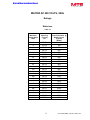
400 Volts, 50HZ 480 Volts, 60HZ 600 Volts, 60HZ USER INSTALLATION MANUAL FORM: MAP-UIM-E REL. July 2013 REV. 015 © 2013 MTE Corporation Matrix AP User Installation Manual IMPORTANT USER INFORMATION NOTICE ® The MTE Corporation Matrix AP Harmonic Filter is designed for harmonic mitigation of 6-pulse inverter drives supplying variable torque loads in a wide variety of applications. The suitability of this filter for a specific application must therefore be determined by the customer. In no event will MTE Corporation assume responsibility or liability for any direct or consequential damages resulting from the use or application of this filter. Nor will MTE Corporation assume patent liability with respect to the use of information, circuits or equipment described in this instruction manual. The Matrix AP Harmonic Filter uses a patent pending Adaptive Passive Harmonic Mitigating Reactor (AP HMR) technology to limit full load current distortion to less than 5% THID and 8% at 30% load. MAPP0320D 1 Form: MAP-TRM-E July 2013 REV. 015 Matrix AP User Installation Manual TABLE OF CONTENTS IMPORTANT USER INFORMATION............................................................................................... 1 TABLE OF CONTENTS .................................................................................................................. 2 INTRODUCTION ............................................................................................................................. 3 SPECIFICATIONS:.......................................................................................................................... 4 AGENCY APPROVALS ..................................................................................................................... 4 PERFORMANCE .............................................................................................................................. 4 ENCLOSURES ................................................................................................................................ 5 WARRANTY .................................................................................................................................... 5 OVER TEMPERATURE SWITCH RATINGS .......................................................................................... 6 INSTALLATION INSTRUCTIONS ................................................................................................ 7 MATRIX AP 400 VOLTS, 50HZ....................................................................................................... 8 RATINGS ....................................................................................................................................... 8 Watts loss................................................................................................................................. 8 REGULATION TABLE ....................................................................................................................... 9 CAPACITOR CURRENTS ................................................................................................................ 10 OPEN STYLE SIZE AND WEIGHTS .................................................................................................. 11 ENCLOSED UNIT SIZE AND W EIGHTS ............................................................................................. 12 MOUNTING PATTERNS............................................................................................................ 13 AP HMR Bolt Hole Mounting Patterns .................................................................................... 13 Capacitor and Cap-panel Bolt Hole Mounting Patterns........................................................... 14 MATRIX AP 480 VOLTS, 60HZ..................................................................................................... 15 RATINGS ..................................................................................................................................... 15 Watts loss............................................................................................................................... 15 REGULATION TABLE ..................................................................................................................... 16 CAPACITOR CURRENTS ................................................................................................................ 17 OPEN STYLE SIZE AND WEIGHTS .................................................................................................. 18 ENCLOSED UNIT SIZE AND W EIGHTS ............................................................................................. 19 MOUNTING PATTERNS............................................................................................................ 20 AP HMR Bolt Hole Mounting Patterns .................................................................................... 20 Capacitor and Cap-panel Bolt Hole Mounting Patterns........................................................... 21 MATRIX AP 600 VOLTS, 60HZ..................................................................................................... 22 RATINGS ..................................................................................................................................... 22 Watts loss............................................................................................................................... 22 REGULATION TABLE ..................................................................................................................... 23 CAPACITOR CURRENTS ................................................................................................................ 24 OPEN STYLE SIZE AND WEIGHTS .................................................................................................. 25 ENCLOSED UNIT SIZE AND W EIGHTS ............................................................................................. 26 MOUNTING PATTERNS............................................................................................................ 27 AP HMR Bolt Hole Mounting Patterns .................................................................................... 27 Capacitor and Cap-panel Bolt Hole Mounting Patterns........................................................... 28 2 Form: MAP-TRM-E July 2013 REV. 015 Matrix AP User Installation Manual AP HMR MOUNTING & TERMINAL LOCATIONS ........................................................................ 29 AP HMR 6 - 44 Amp (400V & 480V)....................................................................................... 29 AP HMR 6 – 34 Amp (600V)................................................................................................... 29 AP HMR 52 - 103 Amp (400V & 480V)................................................................................... 30 AP HMR 44 – 83 Amp (600V)................................................................................................. 30 AP HMR 128 - 320 Amp (400V & 480V) ................................................................................. 31 AP HMR 103 – 208 Amp (600V)............................................................................................. 31 AP HMR 403 - 482 Amp (400V & 480V) ................................................................................. 32 AP HMR 240 – 403 Amp (600V)............................................................................................. 33 AP HMR 636 - 1200 Amp (400V & 480V) ............................................................................... 34 AP HMR 482 – 786 Amp (600V)............................................................................................. 35 CAP-ASSEMBLY MOUNTING & TERMINAL LOCATIONS.......................................................... 36 Figure 20 1 - Three Phase Capacitor................................................................................. 36 Figure 21 3 – High Current Capacitor Panel ....................................................................... 37 ENCLOSED UNIT INTERNAL DETAILS....................................................................................... 38 CAB-12AP.............................................................................................................................. 38 CAB-17AP.............................................................................................................................. 39 CAB-26AP.............................................................................................................................. 40 CAB-26APD ........................................................................................................................... 41 CAB-42AP.............................................................................................................................. 42 CAB-48AP.............................................................................................................................. 43 POWER WIRING CONNECTION .................................................................................................. 44 INPUT AND OUTPUT TERMINAL SPECIFICATIONS ............................................................................. 46 ENCLOSED UNIT INTERCONNECTION DIAGRAM..................................................................... 48 MATRIX AP BASIC SCHEMATIC DIAGRAM ............................................................................... 49 CONTACTOR OPTIONS ............................................................................................................... 50 CONTACTOR COIL SWITCHING CURRENTS............................................................................. 53 STARTUP .................................................................................................................................. 54 SAFETY PRECAUTIONS ................................................................................................................. 54 SEQUENCE OF OPERATION ........................................................................................................... 54 INJURY OR DEATH MAY RESULT IF THE DRIVE SAFETY PRECAUTIONS ARE NOT OBSERVED. DAMAGE TO EQUIPMENT MAY OCCUR IF THE DRIVE STARTUP PROCEDURES ARE NOT OBSERVED ..................................................................................... 54 TROUBLESHOOTING................................................................................................................... 55 MTE MATRIX AP HARMONIC FILTER FIELD CHECKS....................................................................... 56 3 Form: MAP-TRM-E July 2013 REV. 015 Matrix AP User Installation Manual IMPORTANT SAFETY INFORMATION WARNING ONLY A QUALIFIED ELECTRICIAN CAN CARRY OUT THE ELECTRICAL INSTALLATION OF THIS FILTER WARNING High voltage is used in the operation of this filter. Use Extreme caution to avoid contact with high voltage when operating, installing or repairing this filter. INJURY OR DEATH MAY RESULT IF SAFETY PRECAUTIONS ARE NOT OBSERVED. After removing power, allow at least five minutes to elapse and verify that the capacitors have discharged to a safe level before contacting internal components. Connect a DC voltmeter across the capacitor terminals. Start with the meter on the highest scale and progressively switch to a lower scale as the indicated voltage falls below the maximum value of the scale used. WARNING The opening of the branch circuit protective device may be an indication that a fault current has been interrupted. To reduce the risk of fire or electrical shock, current-carrying parts and other components of the filter should be examined and replaced if damaged. WARNING An upstream disconnect/protection device must be used as required by the National Electrical Code (NEC) or governing authority. 1 Form: MAP-UIM-E July 2013 REV. 015 Matrix AP User Installation Manual IMPORTANT SAFETY INFORMATION, CONT. WARNING Even if the upstream disconnect/protection device is open, the drive down stream of the filter may feed back high voltage to the filter. The drive safety instructions must be followed. INJURY OR DEATH MAY RESULT IF SAFETY PRECAUTIONS ARE NOT OBSERVED WARNING The filter must be grounded with a grounding conductor connected to all grounding terminals. WARNING Only spare parts obtained from MTE Corporation or an authorized MTE distributor can be used. WARNING Loose or improperly secured connections may damage or degrade filter performance. Visually inspect and secure all electrical connections before power is applied to the filter. 2 Form: MAP-UIM-E July 2013 REV. 015 Matrix AP User Installation Manual Introduction This manual was specifically developed to assist in the installation and interconnection operation of the MTE Corporation Matrix AP Harmonic Filter. If the equipment is not going to be put into service upon receipt, cover and store the filter in a clean, dry location. After storage, ensure that the equipment is dry and that no condensation or dirt has accumulated on the internal components of the filter before applying power. This manual is intended for use by personnel experienced in the operation and maintenance of electronic drives. Because of the high voltages required by the filter and drive and the potential dangers presented by rotating machinery, it is essential that all personnel involved in the operation and maintenance of this filter know and practice the necessary safety precautions for this type of equipment. Personnel should read and understand the instructions contained in this manual before installing, operating or servicing the filter and the drive to which the filter is connected. Repair/Exchange Procedure MTE Corporation requires a Return Material Authorization Number before it can accept any filters that qualify for return or repair. If problems or questions arise during installation, setup, or operation of the filter, please contact MTE for assistance at: Phone: 262-253-8200 Upon Receipt of this Filter: FAX: 262-253-8222 The MTE AP Harmonic Matrix Filter has been subjected to demanding factory tests before shipment. Carefully inspect the shipping container for damage that may have occurred in transit. Then unpack the filter and carefully inspect for any signs of damage. Save the shipping container for future transport of the filter. In the event of damage, please contact and file a claim with the freight carrier involved immediately. 3 Form: MAP-UIM-E July 2013 REV. 015 Matrix AP User Installation Manual Specifications: Service Conditions Load: 6-pulse variable torque rectifier only Input voltage(s): 480V Version (PN#’s MAPxxxxxD) - 480 VAC +/- 10%, 60 + 0.75 Hz, 3 phase 400V Version (PN#’s MAPxxxxxC) - 400 VAC +/- 10%. 50 + 0.75 Hz. 3 phase 600V Version (PN#’s MAPxxxxxE) - 600 VAC +/- 10%. 60 + 0.75 Hz. 3 phase Input voltage line unbalance: 1% maximum to ensure performance guarantee. Maximum source impedance: 6.00% to ensure performance guarantee. Matrix AP works with Gensets that have source impedance of ~ 15% Minimum source impedance: 1.5% Service Factor: 1.00 Overload: 150% for 1 minute duration with 10% output voltage reduction of nominal of voltage. Ambient Temperature (Operating) Refer to figure 4A for temperature de-rating. Enclosed Filters: Open Panel Filters: Storage Temperature: 320A and above: -40 to +45 degrees C Below 320A: -40 to +40 degrees C -40 to +50 degrees C -40 to +90 degrees C Altitude: 0 to 3300 Feet above sea level. Relative Humidity: 0 to 95% non-condensing Over Voltage: Category ll Agency Approvals UL and cUL listed to UL508 Type MX and CSA-C22.2 No 14-95 File E180243 (3 – 1000 HP, 120VAC through 600 VAC 50, 50/60, 60 Hz Three Phase CE Marked, 400VAC 50 Hz Notes (SCCR): The Short Circuit Current Rating (SCCR) is not required under Exception No.1 of UL508A SB4.2.1 effective 4/25/06. This exception also applies to all the Contactor Options (002, 009, 012, and similar), where the Contactors are separated from the Main Power path by exempt components (such as Reactors) of sufficient Impedance, which is assured in case of the Reactors that are integral components of our Filter. Performance Total Harmonic Current Distortion: 8% MAX at 30% load, 5% MAX at FULL LOAD 4 Form: MAP-UIM-E July 2013 REV. 015 Matrix AP User Installation Manual Enclosures MTE enclosures are designed to provide a degree of protection for electrical components and prevent incidental personnel contact with the enclosed equipment. Depending on the enclosure selected, these enclosures meet the requirements of NEMA 1, 2 or 3R. An approximate cross reference guide between NEMA, UL, CSA and IEC enclosure follows. Type 1 NEMA / IEC IP20 enclosure: Are designed for indoor use and will provide protection against contact with the enclosed equipment. Type 2 NEMA / IEC IP20 enclosure: Are designed for indoor use and will provide protection against contact with the enclosed equipment and provide a degree of protection against limited amounts of falling water and dirt. Type 3R NEMA / IEC IP21 enclosure: Are designed for outdoor use primarily to provide protection against contact with the enclosed equipment and provide a degree of protection against falling rain, sleet, and external ice formation. Warranty Three years from the date of shipment. 5 Form: MAP-UIM-E July 2013 REV. 015 Matrix AP User Installation Manual Over Temperature Switch Ratings Table 1 NC Switch opens at 180 Deg. +/- 5 deg C Current Amps Voltage Contact Load 6 120 AC Resistive Loads 3 120 AC Inductive Loads 3 240 AC Resistive Loads 2.5 240 AC Inductive Loads 8 12 VDC Resistive Loads 4 24 VDC Resistive Loads 6 Form: MAP-UIM-E July 2013 REV. 015 Matrix AP User Installation Manual The capacitor panel must be located in the lowest temperature regions of the enclosure – generally toward the bottom and away from high temperature components. INSTALLATION INSTRUCTIONS Matrix Filters are supplied in the following mechanical configurations: Open Panel Mount Floor mounted general purpose NEMA 2, & 3R cabinets Figures 10 – 35 contain outline drawings for the various ratings and show mounting orientation with bolt patterns. Select a well-ventilated, dust-free area away from direct sunlight, rain or moisture. Do not install in or near a corrosive environment. Avoid locations where the filter would be subjected to excessive vibrations. Include the power dissipation of the filter along with all the other components located in the enclosure to determine the internal temperature rise and cooling requirements of the enclosure. Panel mounted filters are designed for mounting in the vertical plane within the customer’s enclosure. Panel mount units consist of a Harmonic Mitigating Reactor (HMR) and one or more capacitor panel modules referred to as cap-panels on drawings and diagrams. General purpose NEMA 2, and NEMA 3R enclosed filters are designed for floor mounting in the vertical plane in an environment suitable for the enclosure type. Do not install in or near a corrosive environment. Avoid locations where the filter would be subjected to excessive vibrations. Allow a minimum side and back clearance of eight (8) inches and front clearance of thirty-six (36) inches for proper heat dissipation and access. Mount the Harmonic Mitigating Reactor and capacitor module(s) in a location where the ambient temperature does not exceed 50 degrees C. For sufficient ventilation, a general guideline is to allow a side clearance of four (4) inches and a vertical clearance of six (6) inches for proper heat dissipation and access. Minimum clearances depend heavily on airflow within the enclosure. Refer to Article 430 Table 430.91 of the National Electrical code for the selection of the appropriate enclosure Type Number for your application. WARNING Do not install capacitor assembly above/near the Harmonic Mitigating Reactor. Premature or catastrophic failure may occur. 7 Form: MAP-UIM-E July 2013 REV. 015 Matrix AP User Installation Manual MATRIX AP 400 VOLTS, 50Hz Ratings Watts loss Table 10 Maximum Output Amps RMS Efficiency (Typical) (%) 400V Power Dissipation @ Rated Current (Typical) (Watts) 6 97.5% 97.6% 97.9% 98.1% 98.6% 98.7% 98.8% 98.9% 99.0% 99.1% 99.1% 99.2% 99.0% 99.2% 99.2% 99.2% 99.4% 99.4% 99.5% 99.5% 99.6% 99.6% 99.5% 99.6% 114 149 180 206 235 266 298 356 388 459 565 660 973 1,030 1,263 1,423 1,450 1,816 2,008 2,359 2,604 2,974 3,954 4,136 8 11 14 21 27 34 44 52 66 83 103 128 165 208 240 320 403 482 636 786 850 1000 1200 8 Form: MAP-UIM-E July 2013 REV. 015 Matrix AP User Installation Manual MATRIX AP 400 VOLTS, 50Hz Regulation table Table 11 FILTER VOLTAGE REGULATION 400 VAC MAXIMUM OUTPUT VOLTAGE AT NO LOAD RMS PEAK 418 591 MINIMUM OUTPUT VOLTAGE AT FULL LOAD RMS PEAK 384 543 *MAXIMUM PCC VOLTAGE WITH 6% SOURCE IMPEDANCE RMS PEAK 408 577 *Note: PCC is the point of common coupling with the power distribution system 9 Form: MAP-UIM-E July 2013 REV. 015 Matrix AP User Installation Manual MATRIX AP 400 VOLTS, 50Hz Capacitor Currents Table 12 Filter Current Rating Amps RMS 6 8 11 14 21 27 34 44 52 66 83 103 128 165 208 240 320 403 482 636 786 850 1000 1200 Capacitor Current 400V (Typical) Amps RMS 2.145 3.52 4.84 5.39 7.48 10.23 13.145 15.983 19.25 24.904 31.196 38.071 43.978 55.033 72.666 80.63 104.709 138.82 157.553 218.581 271.865 299.255 341.11 420 Note: Ratings are based on IEC AC-3 specifications. 10 Form: MAP-UIM-E July 2013 REV. 015 Matrix AP User Installation Manual MATRIX AP 400 VOLTS, 50Hz Open Style Size and Weights Table 13 Cap-Panel P.N. Capacitor / Capacitor assemblies size Inches Cap Ref. Figure 8.7”H X 8”W X 5.5”D HMR Ref. Figure Figure 10 CAP-350TP 7.5”H X 2.9”D Figure 20 17 8.7”H X 8”W X 5.5”D Figure 10 CAP-351TP 7.5”H X 2.9”D Figure 20 MAPP0011C 26 9.9”H X 9”W X 4.8”D Figure 10 CAP-352TP 7.5”H X 2.9”D Figure 20 14 MAPP0014C 30 9.8”H X 9”W X 5.25”D Figure 10 CAP-353TP 7.5”H X 3.9”D Figure 20 21 MAPP0021C 47 11.7”H X 10.5”W X 6.6”D Figure 10 CAP-342TP 7.5”H X 3.9”D Figure 20 27 MAPP0027C 52 11.7”H X 10.5”W X 7”D Figure 10 CAP-354TP 7.5”H X 4.6”D Figure 20 34 MAPP0034C 62 11.7”H X 10.5”W X 7.6”D Figure 10 CAP-355TP 9.1”H X 4.6”D Figure 20 44 MAPP0044C 74 11.7”H X 10.5”W X 8”D Figure 10 CAP-356TP 9.1”H X 4.6”D Figure 20 52 MAPP0052C 94 14”H X 12”W X 9”D Figure 11 CAP-357TP 10.6”H X 4.6”D Figure 20 66 MAPP0066C 107 14”H X 12”W X 9”D Figure 11 CAP-358TP 10.6”H X 4.6”D Figure 20 83 MAPP0083C 135 14”H X 12”W X 10.9”D Figure 11 CAP-359TP 10.6”H X 4.6”D Figure 20 103 MAPP0103C 145 14”H X 12”W X 10.82”D Figure 11 CAP-360TP 10.6”H X 4.6”D Figure 20 128 MAPP0128C 165 20”H X 15.25”W X 10.7”D Figure 12 594 6.9”H X 16.3”W X 7.6”D Figure 21 165 MAPP0165C 223 20”H X15.25”W X 11.75”D Figure 12 544 7.9”H X 16.3”W X 7.6”D Figure 21 208 MAPP0208C 237 20”H X 15.25”W X 11.85”D Figure 12 543 8.9”H X 16.3”W X7.6”D Figure 21 240 MAPP0240C 327 20”H X 15.25”W X 12.75”D Figure 12 595 7.9”H X 16.3”W X 7.6”D Figure 21 320 MAPP0320C 390 20”H X 15.25”W X 14.8”D Figure 12 596 10.7” X 16.3”W X 7.6”D Figure 21 403 MAPP0403C 433 23.25”H X 15.25”W X13.86”D Figure 13 597 11.5H” X 16.3” X 7.6”D Figure 21 482 MAPP0482C 483 Figure 13 595 7.9”H X 16.3”W X 7.6”D Figure 21 23.25”H X 15.25”W X14.77”D 595 7.9”H X 16.3”W X 7.6”D Figure 21 636 MAPP0636C 736 596 10.7” X 16.3”W X 7.6”D Figure 21 26”H X 24”W X 16.5”D 596 10.7” X 16.3”W X 7.6”D Figure 21 786 MAPP0786C 911 597 11.5H” X 16.3” X 7.6”D Figure 21 26”H X 24”W X 17.8”D 597 11.5H” X 16.3” X 7.6”D Figure 21 596 10.7” X 16.3”W X 7.6”D Figure 21 596 10.7” X 16.3”W X 7.6”D Figure 21 595 7.9”H X 16.3”W X 7.6”D Figure 21 598 10.7H” X 16.3” X 7.6”D Figure 21 598 10.7H” X 16.3” X 7.6”D Figure 21 598 10.7H” X 16.3” X 7.6”D Figure 21 597 11.5H” X 16.3” X 7.6”D Figure 21 597 11.5H” X 16.3” X 7.6”D Figure 21 597 11.5H” X 16.3” X 7.6”D Figure 21 Amps rating Catalog Part Number Total Weight Lbs. HMR Size Inches 6 MAPP0006C 16 8 MAPP0008C 11 850 1000 1200 MAPP0850C MAPP1000C MAPP1200C 983 1137 1297 26”H X 24”W X 20.3”D 26”H X 24”W X 21.7”D 26”H X 24”W X 22.2”D Figure 15 Figure 15 Figure 15 Figure 15 Figure 15 11 Form: MAP-UIM-E July 2013 REV. 015 Matrix AP User Installation Manual MATRIX AP 400 VOLTS, 50Hz Enclosed Unit Size and Weights Table 14 Filter Amps NEMA 2 Enclosure Weight NEMA 3R Enclosure Weight Figure 6 MAPG0006C CAB-12AP2 65 MAPW0006C CAB-12AP3 73 Figure 30 8 MAPG0008C CAB-12AP2 65 MAPW0008C CAB-12AP3 73 Figure 30 11 MAPG0011C CAB-12AP2 75 MAPW0011C CAB-12AP3 82 Figure 30 14 MAPG0014C CAB-12AP2 81 MAPW0014C CAB-12AP3 88 Figure 30 21 MAPG0021C CAB-12AP2 97 MAPW0021C CAB-12AP3 105 Figure 30 27 MAPG0027C CAB-12AP2 104 MAPW0027C CAB-12AP3 111 Figure 30 34 MAPG0034C CAB-12AP2 115 MAPW0034C CAB-12AP3 123 Figure 30 44 MAPG0044C CAB-12AP2 127 MAPW0044C CAB-12AP3 135 Figure 30 52 MAPG0052C CAB-17AP2 174 MAPW0052C CAB-17AP3 181 Figure 31 66 MAPG0066C CAB-17AP2 186 MAPW0066C CAB-17AP3 194 Figure 31 83 MAPG0083C CAB-17AP2 210 MAPW0083C CAB-17AP3 217 Figure 31 103 MAPG0103C CAB-17AP2 221 MAPW0103C CAB-17AP3 228 Figure 31 128 MAPG0128C CAB-26AP2 361 MAPW0128C CAB-26AP3 374 Figure 32 165 MAPG0165C CAB-26AP2 429 MAPW0165C CAB-26AP3 442 Figure 32 208 MAPG0208C CAB-26AP2 444 MAPW0208C CAB-26AP3 457 Figure 32 240 MAPG0240C CAB-26AP2 476 MAPW0240C CAB-26AP3 489 Figure 32 320 MAPG0320C CAB-26APD2 643 MAPW0320C CAB-26APD3 675 Figure 33 403 MAPG0403C CAB-26APD2 637 MAPW0403C CAB-26APD3 669 Figure 33 482 MAPG0482C CAB-42AP2 734 MAPW0482C CAB-42AP3 739 Figure 34 636 MAPG0636C CAB-42AP2 1111 MAPW0636C CAB-42AP3 1116 Figure 34 786 MAPG0786C CAB-42AP2 1260 CAB-42AP3 1264 Figure 34 850 MAPG0850C CAB48AP2 1685 MAPW0786C MAPW0850C CAB-48AP3 1726 Figure 35 1000 MAPG1000C CAB48AP2 1837 MAPW1000C CAB-48AP3 1878 Figure 35 1200 MAPG1200C CAB48AP2 1883 MAPW1200C CAB-48AP3 1924 Figure 35 Note: Weight is shown in pounds 12 Form: MAP-UIM-E July 2013 REV. 015 Matrix AP User Installation Manual MATRIX AP 400 VOLTS, 50Hz MOUNTING PATTERNS AP HMR Bolt Hole Mounting Patterns Table 15 8.7”H X 8”W X 5.5”D Rear Mount Centerline 7”A X 7.2”B Base Mount Centerline 2.8”C X 7.2”E 17 8.7”H X 8”W X 5.5”D 7”A X 7.2”B 2.8”C X 7.2”E Mounting Holes .28” DIA .28” DIA MAPP0011C 26 9.9”H X 9”W X 4.8”D 8.2”A X 8.2”B 2.75”C X 8.2”E .28” DIA Figure 10 MAPP0014C 30 9.8”H X 9”W X 5.25”D 8.15”A X 8.2”B 3.25”C X 8.2”E .28” DIA Figure 10 3.5”C X 9.7”E .28” DIA Figure 10 4”C X 9.7”E .28” DIA Figure 10 Figure 10 Part Number Lbs. Overall Size MAPP0006C 16 MAPP0008C MAPP0021C MAPP0027C 47 52 11.7”H X 10.5”W X 6.6”D 11.7”H X 10.5”W X 7”D 9.8”A X 9.7”B 9.9”A X 9.7”B Figure Figure 10 Figure 10 MAPP0034C 62 11.7”H X 10.5”W X 7.6”D 9.8”A X 9.7”B 4.5”C X 9.7”E .28” DIA MAPP0044C 74 11.7”H X 10.5”W X 8”D 9.8”A X 9.7”B 5”C X 9.7”E .28” DIA Figure 10 MAPP0052C 94 14”H X 12”W X 9”D 12”A X 11”B 5.4”C X 11”E .340” DIA Figure 11 MAPP0066C 107 14”H X 12”W X 9”D 12”A X 11”B 5.9”C X 11”E .340” DIA Figure 11 MAPP0083C 133 14”H X 12”W X 10.9”D 11.96''A x 11''B 6.5”C X 11”E .340” DIA Figure 11 MAPP0103C 144 14”H X 12”W X 10.8”D 12.05'A x 11''B 6.5”C X 11”E .340” DIA Figure 11 MAPP0128C 149 20”H X 15.25”W X 10.7”D 17.37”A X 14”B 6”C X 14”E .413” DIA Figure 12 MAPP0165C 257 20”H X15.25”W X 11.75”D 17.32”A X 14”B 7”C X 14”E .413” DIA Figure 12 MAPP0208C 270 20”H X 15.25”W X 11.85”D 17.47”A X 14”B 7”C X 14”E .413” DIA Figure 12 MAPP0240C 310 20”H X 15.25”W X 12.75”D 17.51”A X 14”B 8”C X 14”E .413” DIA Figure 12 MAPP0320C 397 20”H X 15.25”W X 14.8”D 17.55”A X 14”B 10”C x 14”E .413” DIA Figure 12 MAPP0403C 433 23.25”H X 15.25”W X13.86”D 20.64”A X 14”B 9.2”C x 14”E .413” DIA Figure 13 MAPP0482C 483 23.3”H X 15.25”W X14.77”D 20.60”A X 14”B 10.06”C X 14”E .413” DIA Figure 13 MAPP0636C 793 26”H X 24”W X 16.5”D N/A 9.15”C X 22”E 1” DIA Figure 15 MAPP0786C 970 26”H X 24”W X 17.8”D N/A 10.65”C X 22”E 1” DIA Figure 15 MAPP0850C 1070 26”H X 24”W X 20.03”D N/A 10.65”C X 22”E 1” DIA Figure 15 MAPP1000C 1213 26”H X 24”W X 21.7”D N/A 12.15”C X 22”E 1” DIA Figure 15 MAPP1200C 1365 26”H X 24”W X 22.2”D N/A 13.65”C X 22”E 1” DIA Figure 15 Use the above table and referenced figures to establish suitable reactor mounting. 13 Form: MAP-UIM-E July 2013 REV. 015 Matrix AP User Installation Manual MATRIX AP 400 VOLTS, 50Hz Capacitor and Cap-panel Bolt Hole Mounting Patterns Table 16 Part Number MAPP0006C CAP-350TP Weight Lbs. 1.8 Mounting Holes Figure 7.5”H X 2.9”D Rear Mount Centerline N/A M12 STUD Figure 20 MAPP0008C CAP-351TP 2.2 7.5”H X 2.9”D N/A M12 STUD Figure 20 MAPP0011C CAP-352TP 2.3 7.5”H X 2.9”D N/A M12 STUD Figure 20 MAPP0014C CAP-353TP 2.64 7.5”H X 3.9”D N/A M12 STUD Figure 20 MAPP0021C CAP-342TP 3.2 7.5”H X 3.9”D N/A M12 STUD Figure 20 MAPP0027C CAP-354TP 4.0 7.5”H X 4.6”D N/A M12 STUD Figure 20 MAPP0034C CAP-355TP 4.1 9.1”H X 4.6”D N/A M12 STUD Figure 20 MAPP0044C CAP-356TP 5.0 9.1”H X 4.6”D N/A M12 STUD Figure 20 MAPP0052C CAP-357TP 6.0 10.6”H X 4.6”D N/A M12 STUD Figure 20 MAPP0066C CAP-358TP 6.0 10.6”H X 4.6”D N/A M12 STUD Figure 20 MAPP0083C CAP-359TP 6.45 10.6”H X 4.6”D N/A M12 STUD Figure 20 MAPP0103C CAP-360TP 6.45 10.6”H X 4.6”D N/A M12 STUD Figure 20 MAPP0128C 594 16 6.9”H X 16.3”W X 7.6”D 3.77”A x 15.81”B .280” DIA Figure 21 MAPP0165C 544 18 7.9”H X 16.3”W X 7.6”D 3.77”A x 15.81”B .280” DIA Figure 21 MAPP0208C 543 20 8.9”H X 16.3”W X7.6”D 3.77”A x 15.81”B .280” DIA Figure 21 MAPP0240C 595 18 7.9”H X 16.3”W X 7.6”D 3.77”A x 15.81”B .280” DIA Figure 21 MAPP0320C 596 23 10.7” X 16.3”W X 7.6”D 3.77”A x 15.81”B .280” DIA Figure 21 MAPP0403C 597 23 11.5” X 16.3” X 7.6”D 3.77”A x 15.81”B .280” DIA Figure 21 595 18 7.9”H X 16.3”W X 7.6”D 3.77”A x 15.81”B .280” DIA Figure 21 595 18 7.9”H X 16.3”W X 7.6”D 3.77”A x 15.81”B .280” DIA Figure 21 596 23 10.7” X 16.3”W X 7.6”D 3.77”A x 15.81”B .280” DIA Figure 21 596 23 10.7” X 16.3”W X 7.6”D 3.77”A x 15.81”B .280” DIA Figure 21 597 23 11.5” X 16.3” X 7.6”D 3.77”A x 15.81”B .280” DIA Figure 21 597 23 11.5” X 16.3” X 7.6”D 3.77”A x 15.81”B .280” DIA Figure 21 596 23 10.7” X 16.3”W X 7.6”D 3.77”A x 15.81”B .280” DIA Figure 21 596 23 10.7” X 16.3”W X 7.6”D 3.77”A x 15.81”B .280” DIA Figure 21 595 18 7.9”H X 16.3”W X 7.6”D 3.77”A x 15.81”B .280” DIA Figure 21 598 23 10.7” X 16.3”W X 7.6”D 3.77”A x 15.81”B .280” DIA Figure 21 598 23 10.7” X 16.3”W X 7.6”D 3.77”A x 15.81”B .280” DIA Figure 21 598 23 10.7” X 16.3” X 7.6”D 3.77”A x 15.81”B .280” DIA Figure 21 597 23 11.5” X 16.3” X 7.6”D 3.77”A x 15.81”B .280” DIA Figure 21 597 23 11.5” X 16.3” X 7.6”D 3.77”A x 15.81”B .280” DIA Figure 21 597 23 11.5” X 16.3” X 7.6”D 3.77”A x 15.81”B .280” DIA Figure 21 MAPP0482C MAPP0636C MAPP0786C MAPP0850C MAPP1000C MAPP1200C CAP P.N. Overall Size Note: Units above 403 amps require multiple parallel cap panels. 14 Form: MAP-UIM-E July 2013 REV. 015 Matrix AP User Installation Manual MATRIX AP 480 VOLTS, 60Hz Ratings Watts loss Table 20 Maximum Output Amps RMS Efficiency (Typical) (%) 480V Power Dissipation @ Rated Current (Typical) (Watts) 6 97.5% 97.6% 97.9% 98.1% 98.6% 98.7% 98.8% 98.9% 99.0% 99.1% 99.1% 99.2% 99.0% 99.2% 99.2% 99.2% 99.4% 99.4% 99.5% 99.5% 99.6% 99.6% 99.5% 99.6% 122 158 192 220 251 283 318 379 413 488 600 702 1,035 1,096 1,343 1,514 1,543 1,932 2,137 2,509 2,771 3,163 4,206 4,400 8 11 14 21 27 34 44 52 66 83 103 128 165 208 240 320 403 482 636 786 850 1000 1200 15 Form: MAP-UIM-E July 2013 REV. 015 Matrix AP User Installation Manual MATRIX AP 480 VOLTS, 60Hz Regulation table Table 21 FILTER VOLTAGE REGULATION 480 VAC MAXIMUM OUTPUT VOLTAGE AT NO LOAD RMS PEAK 502 710 MINIMUM OUTPUT VOLTAGE AT FULL LOAD RMS PEAK 460 600 *MAXIMUM PCC VOLTAGE WITH 6% SOURCE IMPEDANCE RMS PEAK 490 693 Note: PCC is the point of common coupling with the power distribution system 16 Form: MAP-UIM-E July 2013 REV. 015 Matrix AP User Installation Manual MATRIX AP 480 VOLTS, 60Hz Capacitor Currents Table 22 Filter Current Rating Amps RMS 6 8 11 14 21 27 34 44 52 66 83 103 128 165 208 240 320 403 482 636 786 850 1000 1200 Capacitor Current 480V (Typical) Amps RMS 1.98 2.64 3.7 4.62 6.93 9.24 11.8 14.52 17.16 22.16 29.2 34.7 39.8 53.2 64.8 72.7 94.5 132.3 141.8 195.6 245.0 265.9 308.6 355.2 Note: Ratings are based on IEC AC-3 specifications. 17 Form: MAP-UIM-E July 2013 REV. 015 Matrix AP User Installation Manual MATRIX AP 480 VOLTS, 60Hz Open Style Size and Weights Table 23 Cap-Panel P.N. Capacitor / Capacitor assemblies size Inches Cap Ref. Figure 8.7”H X 8”W X 5.5”D HMR Ref. Figure Figure 10 CAP-338TP 7.5”H X 2.9”D Figure 20 17 8.7”H X 8”W X 5.5”D Figure 10 CAP-339TP 7.5”H X 2.9”D Figure 20 MAPP0011D 26 9.9”H X 9”W X 4.8”D Figure 10 CAP-349TP 7.5”H X 2.9”D Figure 20 14 MAPP0014D 30 9.8”H X 9”W X 5.25”D Figure 10 CAP-340TP 7.5”H X 2.9”D Figure 20 21 MAPP0021D 47 11.7”H X 10.5”W X 6.6”D Figure 10 CAP-341TP 7.5”H X 3.9”D Figure 20 27 MAPP0027D 52 11.7”H X 10.5”W X 7”D Figure 10 CAP-342TP 7.5”H X 3.9”D Figure 20 34 MAPP0034D 62 11.7”H X 10.5”W X 7.6”D Figure 10 CAP-343TP 7.5”H X 3.9”D Figure 20 44 MAPP0044D 74 11.7”H X 10.5”W X 8”D Figure 10 CAP-344TP 7.5”H X 4.6”D Figure 20 52 MAPP0052D 94 14”H X 12”W X 9”D Figure 11 CAP-345TP 9.2”H X 4.6”D Figure 20 66 MAPP0066D 107 14”H X 12”W X 9”D Figure 11 CAP-346TP 9.2”H X 4.6”D Figure 20 83 MAPP0083D 135 14”H X 12”W X 10.9”D Figure 11 CAP-347TP 10.6”H X 4.6”D Figure 20 103 MAPP0103D 145 14”H X 12”W X 10.82”D Figure 11 CAP-348TP 10.6”H X 4.6”D Figure 20 128 MAPP0128D 165 20”H X 15.25”W X 10.7”D Figure 12 555 6.9”H X 16.3”W X 7.6”D Figure 21 165 MAPP0165D 223 20”H X15.25”W X 11.75”D Figure 12 557 6.9”H X 16.3”W X 7.6”D Figure 21 208 MAPP0208D 237 20”H X 15.25”W X 11.85”D Figure 12 545 7.9”H X 16.3”W X7.6”D Figure 21 240 MAPP0240D 327 20”H X 15.25”W X 12.75”D Figure 12 544 7.9”H X 16.3”W X 7.6”D Figure 21 320 MAPP0320D 390 20”H X 15.25”W X 14.8”D Figure 12 543 8.9” X 16.3”W X 7.6”D Figure 21 403 MAPP0403D 433 23.25”H X 15.25”W X13.86”D Figure 13 562 10.7” X 16.3” X 7.6”D Figure 21 482 MAPP0482D 483 23.25”H X 15.25”W X14.77”D Figure 13 544 7.9”H X 16.3”W X 7.6”D Figure 21 544 7.9”H X 16.3”W X 7.6”D Figure 21 636 MAPP0636D 736 26”H X 24”W X 16.5”D 543 8.9” X 16.3”W X 7.6”D Figure 21 543 8.9” X 16.3”W X 7.6”D Figure 21 786 MAPP0786D 911 26”H X 24”W X 17.8”D 562 10.7” X 16.3” X 7.6”D Figure 21 562 10.7” X 16.3” X 7.6”D Figure 21 543 8.9” X 16.3”W X 7.6”D Figure 21 543 8.9” X 16.3”W X 7.6”D Figure 21 544 7.9”H X 16.3”W X 7.6”D Figure 21 543 8.9” X 16.3”W X 7.6”D Figure 21 543 8.9” X 16.3”W X 7.6”D Figure 21 561 10.7” X 16.3” X 7.6”D Figure 21 562 10.7” X 16.3” X 7.6”D Figure 21 562 10.7” X 16.3” X 7.6”D Figure 21 562 10.7” X 16.3” X 7.6”D Figure 21 Amps rating Catalog Part Number Total Weight Lbs. HMR Size Inches 6 MAPP0006D 16 8 MAPP0008D 11 850 1000 1200 MAPP0850D MAPP1000D MAPP1200D 983 1137 1297 26”H X 24”W X 20.3”D 26”H X 24”W X 21.7”D 26”H X 24”W X 22.2”D Figure 15 Figure 15 Figure 15 Figure 15 Figure 15 18 Form: MAP-UIM-E July 2013 REV. 015 Matrix AP User Installation Manual MATRIX AP 480 VOLTS, 60Hz Enclosed Unit Size and Weights Table 24 Filter Amps NEMA 2 Enclosure Weight NEMA 3R Enclosure Weight Figure 6 MAPG0006D CAB-12AP2 64 MAPW0006D CAB-12AP3 72 Figure 30 8 MAPG0008D CAB-12AP2 65 MAPW0008D CAB-12AP3 73 Figure 30 11 MAPG0011D CAB-12AP2 74 MAPW0011D CAB-12AP3 82 Figure 30 14 MAPG0014D CAB-12AP2 79 MAPW0014D CAB-12AP3 87 Figure 30 21 MAPG0021D CAB-12AP2 97 MAPW0021D CAB-12AP3 105 Figure 30 27 MAPG0027D CAB-12AP2 101 MAPW0027D CAB-12AP3 109 Figure 30 34 MAPG0034D CAB-12AP2 112 MAPW0034D CAB-12AP3 120 Figure 30 44 MAPG0044D CAB-12AP2 125 MAPW0044D CAB-12AP3 133 Figure 30 52 MAPG0052D CAB-17AP2 172 MAPW0052D CAB-17AP3 179 Figure 31 66 MAPG0066D CAB-17AP2 185 MAPW0066D CAB-17AP3 192 Figure 31 83 MAPG0083D CAB-17AP2 209 MAPW0083D CAB-17AP3 217 Figure 31 103 MAPG0103D CAB-17AP2 313 MAPW0103D CAB-17AP3 321 Figure 31 128 MAPG0128D CAB-26AP2 333 MAPW0128D CAB-26AP3 347 Figure 32 165 MAPG0165D CAB-26AP2 392 MAPW0165D CAB-26AP3 406 Figure 32 208 MAPG0208D CAB-26AP2 405 MAPW0208D CAB-26AP3 419 Figure 32 240 MAPG0240D CAB-26AP2 489 MAPW0240D CAB-26AP3 503 Figure 32 320 MAPG0320D CAB-26APD2 630 MAPW0320D CAB-26APD3 656 Figure 33 403 MAPG0403D CAB-26APD2 673 MAPW0403D CAB-26APD3 700 Figure 33 482 MAPG0482D CAB-42AP2 702 MAPW0482D CAB-42AP3 710 Figure 34 636 MAPG0636D CAB-42AP2 1077 MAPW0636D CAB-42AP3 1084 Figure 34 786 MAPG0786D CAB-42AP2 1252 MAPW0786D CAB-42AP3 1260 Figure 34 850 MAPG0850D CAB48AP2 1386 MAPW0850D CAB-48AP3 1393 Figure 35 1000 MAPG1000D CAB48AP2 1640 MAPW1000D CAB-48AP3 1647 Figure 35 1200 MAPG1200D CAB48AP2 1700 MAPW1200D CAB-48AP3 1707 Figure 35 Note: Weight is shown in pounds 19 Form: MAP-UIM-E July 2013 REV. 015 Matrix AP User Installation Manual MATRIX AP 480 VOLTS, 60Hz MOUNTING PATTERNS AP HMR Bolt Hole Mounting Patterns Table 25 8.7”H X 8”W X 5.5”D Rear Mount Centerline 7”A X 7.2”B Base Mount Centerline 2.8”C X 7.2”E 8.7”H X 8”W X 5.5”D 7”A X 7.2”B 2.8”C X 7.2”E Mounting Holes .28” DIA .28” DIA 2.75”C X 8.2”E .28” DIA Figure 10 3.25”C X 8.2”E .28” DIA Figure 10 3.5”C X 9.7”E .28” DIA Figure 10 Figure 10 Part Number Lbs. Overall Size MAPP0006D 16 MAPP0008D 17 MAPP0011D MAPP0014D 26 30 9.9”H X 9”W X 4.8”D 9.8”H X 9”W X 5.25”D 8.2”A X 8.2”B 8.15”A X 8.2”B 9.8”A X 9.7”B Figure Figure 10 Figure 10 MAPP0021D 47 11.7”H X 10.5”W X 6.6”D MAPP0027D 52 11.7”H X 10.5”W X 7”D 9.9”A X 9.7”B 4”C X 9.7”E .28” DIA MAPP0034D 62 11.7”H X 10.5”W X 7.6”D 9.8”A X 9.7”B 4.5”C X 9.7”E .28” DIA Figure 10 MAPP0044D 74 11.7”H X 10.5”W X 8”D 9.8”A X 9.7”B 5”C X 9.7”E .28” DIA Figure 10 MAPP0052D 94 14”H X 12”W X 9”D 12”A X 11”B 5.4”C X 11”E .340” DIA Figure 11 MAPP0066D 107 14”H X 12”W X 9”D 12”A X 11”B 5.9”C X 11”E .340” DIA Figure 11 MAPP0083D 133 15.7”H X 12”W X 10.7”D 11.96''A x 11''B 6.5”C X 11”E .340” DIA Figure 11 MAPP0103D 144 15.7”H X 12”W X 11.1”D 12.05'A x 11''B 6.5”C X 11”E .340” DIA Figure 11 MAPP0128D 149 20”H X 15.25”W X 10.7”D 17.37”A X 14”B 6”C X 14”E .413” DIA Figure 12 MAPP0165D 257 20”H X15.25”W X 11.75”D 17.32”A X 14”B 7”C X 14”E .413” DIA Figure 12 MAPP0208D 270 20”H X 15.25”W X 11.85”D 17.47”A X 14”B 7”C X 14”E .413” DIA Figure 12 MAPP0240D 310 20”H X 15.25”W X 12.75”D 17.51”A X 14”B 8”C X 14”E .413” DIA Figure 12 MAPP0320D 397 20”H X 15.25”W X 14.8”D 17.55”A X 14”B 10”C x 14”E .413” DIA Figure 12 MAPP0403D 433 23.25”H X 15.25”W X13.86”D 20.64”A X 14”B 9.2”C x 14”E .413” DIA Figure 13 MAPP0482D 483 23.3”H X 15.25”W X14.37”D 20.60”A X 14”B 10.06”C X 14”E .413” DIA Figure 13 MAPP0636D 793 26”H X 24”W X 16.5”D N/A 9.15”C X 22”E 1” DIA Figure 15 MAPP0786D 970 26”H X 24”W X 17.8”D N/A 10.65”C X 22”E 1” DIA Figure 15 MAPP0850D 1070 26”H X 24”W X 20.3”D N/A 10.65”C X 22”E 1” DIA Figure 15 MAPP1000D 1213 26”H X 24”W X 21.7”D N/A 12.15”C X 22”E 1” DIA Figure 15 MAPP1200D 1365 26”H X 24”W X 22.2”D N/A 13.65”C X 22”E 1” DIA Figure 15 Use the above table and referenced figures to establish suitable reactor mounting. 20 Form: MAP-UIM-E July 2013 REV. 015 Matrix AP User Installation Manual MATRIX AP 480 VOLTS, 60Hz Capacitor and Cap-panel Bolt Hole Mounting Patterns Table 26 Part Number CAP P.N. MAPP0006D CAP-338TP Weight Lbs. 1.8 Mounting Holes Figure 7.5”H X 2.9”D Rear Mount Centerline N/A M12 STUD Figure 20 MAPP0008D CAP-339TP 1.95 7.5”H X 2.9”D N/A M12 STUD Figure 20 MAPP0011D CAP-349TP 2.1 7.5”H X 2.9”D N/A M12 STUD Figure 20 MAPP0014D CAP-340TP 2.3 7.5”H X 2.9”D N/A M12 STUD Figure 20 MAPP0021D CAP-341TP 2.65 7.5”H X 3.9”D N/A M12 STUD Figure 20 MAPP0027D CAP-342TP 3.2 7.5”H X 3.9”D N/A M12 STUD Figure 20 MAPP0034D CAP-343TP 3.7 7.5”H X 3.9”D N/A M12 STUD Figure 20 MAPP0044D CAP-344TP 4.0 7.5”H X 4.6”D N/A M12 STUD Figure 20 MAPP0052D CAP-345TP 4.1 9.2”H X 4.6”D N/A M12 STUD Figure 20 MAPP0066D CAP-346TP 5.0 9.2”H X 4.6”D N/A M12 STUD Figure 20 MAPP0083D CAP-347TP 6.0 10.6”H X 4.6”D N/A M12 STUD Figure 20 MAPP0103D CAP-348TP 6.45 10.6”H X 4.6”D N/A M12 STUD Figure 20 MAPP0128D 555 16 6.9”H X 16.3”W X 7.6”D 3.77”A x 15.81”B .280” DIA Figure 21 MAPP0165D 557 16 6.9”H X 16.3”W X 7.6”D 3.77”A x 15.81”B .280” DIA Figure 21 MAPP0208D 545 18 7.9”H X 16.3”W X7.6”D 3.77”A x 15.81”B .280” DIA Figure 21 MAPP0240D 544 18 7.9”H X 16.3”W X 7.6”D 3.77”A x 15.81”B .280” DIA Figure 21 MAPP0320D 543 20 8.9” X 16.3”W X 7.6”D 3.77”A x 15.81”B .280” DIA Figure 21 MAPP0403D 562 23 10.7” X 16.3” X 7.6”D 3.77”A x 15.81”B .280” DIA Figure 21 544 18 7.9”H X 16.3”W X 7.6”D 3.77”A x 15.81”B .280” DIA Figure 21 544 18 7.9”H X 16.3”W X 7.6”D 3.77”A x 15.81”B .280” DIA Figure 21 543 20 8.9” X 16.3”W X 7.6”D 3.77”A x 15.81”B .280” DIA Figure 21 543 20 8.9” X 16.3”W X 7.6”D 3.77”A x 15.81”B .280” DIA Figure 21 562 23 10.7” X 16.3” X 7.6”D 3.77”A x 15.81”B .280” DIA Figure 21 562 23 10.7” X 16.3” X 7.6”D 3.77”A x 15.81”B .280” DIA Figure 21 543 20 8.9” X 16.3”W X 7.6”D 3.77”A x 15.81”B .280” DIA Figure 21 543 20 8.9” X 16.3”W X 7.6”D 3.77”A x 15.81”B .280” DIA Figure 21 544 18 7.9”H X 16.3”W X 7.6”D 3.77”A x 15.81”B .280” DIA Figure 21 543 20 8.9” X 16.3”W X 7.6”D 3.77”A x 15.81”B .280” DIA Figure 21 543 20 8.9” X 16.3”W X 7.6”D 3.77”A x 15.81”B .280” DIA Figure 21 561 23 10.7” X 16.3” X 7.6”D 3.77”A x 15.81”B .280” DIA Figure 21 562 23 10.7” X 16.3” X 7.6”D 3.77”A x 15.81”B .280” DIA Figure 21 562 23 10.7” X 16.3” X 7.6”D 3.77”A x 15.81”B .280” DIA Figure 21 562 23 10.7” X 16.3” X 7.6”D 3.77”A x 15.81”B .280” DIA Figure 21 MAPP0482D MAPP0636D MAPP0786D MAPP0850D MAPP1000D MAPP1200D Overall Size Note: Units above 403 amps require multiple parallel cap panels. Use the above table and referenced figures to establish suitable Cap-panel mounting. 21 Form: MAP-UIM-E July 2013 REV. 015 Matrix AP User Installation Manual MATRIX AP 600 VOLTS, 60Hz Ratings Watts loss Table 30 Maximum Output Amps RMS Efficiency (Typical) (%) 600V Power Dissipation @ Rated Current (Typical) (Watts) 6 97.6% 97.8% 98.2% 98.3% 98.7% 98.9% 99.0% 99.1% 99.1% 99.0% 99.1% 99.0% 99.2% 99.3% 99.3% 99.3% 99.4% 99.5% 99.5% 99.6% 99.6% 150 183 205 250 285 304 366 395 494 655 718 1085 1090 1285 1431 1624 2021 2208 2481 2884 3368 8 11 14 21 27 34 44 52 66 83 103 128 165 208 240 320 403 482 636 786 22 Form: MAP-UIM-E July 2013 REV. 015 Matrix AP User Installation Manual MATRIX AP 600 VOLTS, 60Hz Regulation table Table 31 FILTER VOLTAGE REGULATION 600 VAC MAXIMUM OUTPUT VOLTAGE AT NO LOAD RMS PEAK 627 885 MINIMUM OUTPUT VOLTAGE AT FULL LOAD RMS PEAK 575 750 *MAXIMUM PCC VOLTAGE WITH 6% SOURCE IMPEDANCE RMS PEAK 612 864 *Note: PCC is the point of common coupling with the power distribution system 23 Form: MAP-UIM-E July 2013 REV. 015 Matrix AP User Installation Manual MATRIX AP 600 VOLTS, 60Hz Capacitor Currents Table 32 Filter Current Rating Amps RMS 6 8 11 14 21 27 34 44 52 66 83 103 128 165 208 240 320 403 482 636 786 Capacitor Current 600V (Typical) Amps RMS 1.98 2.64 3.7 4.62 6.93 9.24 11.8 14.52 17.16 22.16 29.2 34.7 39.8 53.2 64.8 72.7 94.5 132.3 141.8 195.6 245.0 Note: Ratings are based on IEC AC-3 specifications. 24 Form: MAP-UIM-E July 2013 REV. 015 Matrix AP User Installation Manual MATRIX AP 600 VOLTS, 60Hz Open Style Size and Weights Table 33 Amps rating Catalog Part Number Total Weight Lbs. HMR Size Inches HMR Ref. Figure Cap-Panel P.N. Capacitor / Capacitor assemblies size Inches Cap Ref. Figure 6 MAPP0006E 17 8.7”H X 8”W X 5.5”D Figure 10 CAP-361TP 7.5”H X 2.9”D Figure 20 8 MAPP0008E 26 9.8”H X 9”W X 4.8”D Figure 10 CAP-362TP 7.5”H X 2.9”D Figure 20 11 MAPP0011E 30 9.8”H X 9”W X 5.3”D Figure 10 CAP-363TP 7.5”H X 2.9”D Figure 20 14 MAPP0014E 47 11.7”H X 10.5”W X 6.6”D Figure 10 CAP-364TP 7.5”H X 3.9”D Figure 20 21 MAPP0021E 52 11.7”H X 10.5”W X 7.1”D Figure 10 CAP-365TP 7.5”H X 3.9”D Figure 20 27 MAPP0027E 62 11.7”H X 10.5”W X 7.6”D Figure 10 CAP-366TP 7.5”H X 4.6D Figure 20 34 MAPP0034E 74 11.7”H X 10.5”W X 8.1”D Figure 10 CAP-367TP 7.5”H X 4.6”D Figure 20 44 MAPP0044E 94 14”H X 12”W X 9.89”D Figure 11 CAP-368TP 9.14”H X 4.6”D Figure 20 52 MAPP0052E 107 14”H X 12”W X 10.3”D Figure 11 CAP-369TP 9.14”H X 4.6”D Figure 20 66 MAPP0066E 135 14”H X 12”W X 11”D Figure 11 CAP-370TP 10.6”H X 4.6”D Figure 20 83 MAPP0083E 140 14.1”H X 12”W X 11”D Figure 11 CAP-371TP 10.6”H X 4.6”D Figure 20 103 MAPP0103E 165 20”H X 15.3”W X 10.7”D Figure 12 567 6.9”H X 16.3”W X 7.6”D Figure 21 128 MAPP0128E 223 20”H X 15.3”W X 11.7”D Figure 12 568 6.9”H X 16.3”W X 7.6”D Figure 21 165 MAPP0165E 237 20.1”H X15.3”W X 11.9”D Figure 12 570 6.9”H X 16.3”W X 7.6”D Figure 21 208 MAPP0208E 337 20.1”H X 15.3”W X 13.4”D Figure 12 572 7.9”H X 16.3”W X7.6”D Figure 21 240 MAPP0240E 433 20”H X 15.3”W X 16.1”D Figure 14 574 8.9”H X 16.3”W X 7.6”D Figure 21 320 MAPP0320E 477 23.3”H X 15.3”W X 15.7”D Figure 12 576 10.7” X 16.3”W X 7.6”D Figure 21 403 MAPP0403E 483 23.3”H X 15.3”W X16.1”D Figure 13 578 11.5” X 16.3” X 7.6”D Figure 21 482 MAPP0482E 736 25.8”H X 24”W X16.7”D Figure 16 574 8.9”H X 16.3”W X 7.6”D Figure 21 574 8.9”H X 16.3”W X 7.6”D Figure 21 636 MAPP0636E 911 25.9”H X 24”W X 18.2”D 576 10.7” X 16.3”W X 7.6”D Figure 21 576 10.7” X 16.3”W X 7.6”D Figure 21 786 MAPP0786E 1137 25”H X 24”W X 19.5”D 578 11.5” X 16.3” X 7.6”D Figure 21 578 11.5” X 16.3” X 7.6”D Figure 21 Figure 16 Figure 16 25 Form: MAP-UIM-E July 2013 REV. 015 Matrix AP User Installation Manual MATRIX AP 600 VOLTS, 60Hz Enclosed Unit Size and Weights Table 34 Filter Amps NEMA 2 Enclosure Weight NEMA 3R Enclosure Weight Figure 6 MAPG0006E CAB-12AP2 65 MAPW0006E CAB-12AP3 73 Figure 30 8 MAPG0008E CAB-12AP2 74 MAPW0008E CAB-12AP3 82 Figure 30 11 MAPG0011E CAB-12AP2 79 MAPW0011E CAB-12AP3 87 Figure 30 14 MAPG0014E CAB-12AP2 97 MAPW0014E CAB-12AP3 105 Figure 30 21 MAPG0021E CAB-12AP2 101 MAPW0021E CAB-12AP3 109 Figure 30 27 MAPG0027E CAB-12AP2 112 MAPW0027E CAB-12AP3 120 Figure 30 34 MAPG0034E CAB-12AP2 125 MAPW0034E CAB-12AP3 133 Figure 30 44 MAPG0044E CAB-17AP2 172 MAPW0044E CAB-17AP3 179 Figure 31 52 MAPG0052E CAB-17AP2 185 MAPW0052E CAB-17AP3 192 Figure 31 66 MAPG0066E CAB-17AP2 209 MAPW0066E CAB-17AP3 217 Figure 31 83 MAPG0083E CAB-17AP2 313 MAPW0083E CAB-17AP3 338 Figure 31 103 MAPG0103E CAB-26AP2 333 MAPW0103E CAB-26AP3 358 Figure 32 128 MAPG0128E CAB-26AP2 392 MAPW0128E CAB-26AP3 417 Figure 32 165 MAPG0165E CAB-26AP2 405 MAPW0165E CAB-26AP3 430 Figure 32 208 MAPG0208E CAB-26AP2 489 MAPW0208E CAB-26AP3 514 Figure 32 240 MAPG0240E CAB-26APD2 630 MAPW0240E CAB-26APD3 656 Figure 33 320 MAPG0320E CAB-26APD2 673 MAPW0320E CAB-26APD3 700 Figure 33 403 MAPG0403E CAB-42AP2 702 MAPW0403E CAB-42AP3 710 Figure 34 482 MAPG0482E CAB-42AP2 1077 MAPW0482E CAB-42AP3 1085 Figure 34 636 MAPG0636E CAB-42AP2 1252 MAPW0636E CAB-42AP3 1260 Figure 34 786 MAPG0786E CAB-48AP2 1640 MAPW0786E CAB-48AP3 1647 Figure 35 Note: Weight is shown in pounds. 26 Form: MAP-UIM-E July 2013 REV. 015 Matrix AP User Installation Manual MATRIX AP 600 VOLTS, 60Hz MOUNTING PATTERNS AP HMR Bolt Hole Mounting Patterns Table 35 8.7”H X 8”W X 5.5”D Rear Mount Centerline 7”A X 7.2”B Base Mount Centerline 2.8”C X 7.2”E 8.7”H X 8”W X 5.5”D 8.2”A X 8.2”B 2.8”C X 8.2”E Mounting Holes .28” DIA .28” DIA 3.3”C X 8.2”E .28” DIA Figure 10 3.5”C X 9.7”E .28” DIA Figure 10 4”C X 9.7”E .28” DIA Figure 10 Figure 10 Part Number Lbs. Overall Size MAPP0006E 17 MAPP0008E 26 MAPP0011E MAPP0014E 30 47 9.9”H X 9”W X 4.8”D 9.8”H X 9”W X 5.25”D 8.1”A X 8.2”B 9.9”A X 9.7”B 9.9”A X 9.7”B Figure Figure 10 Figure 10 MAPP0021E 52 11.7”H X 10.5”W X 6.6”D MAPP0027E 62 11.7”H X 10.5”W X 7”D 9.9”A X 9.7”B 4.5”C X 9.7”E .28” DIA MAPP0034E 74 11.7”H X 10.5”W X 7.6”D 9.9”A X 9.7”B 5”C X 9.7”E .28” DIA Figure 10 MAPP0044E 94 11.7”H X 10.5”W X 8”D 12”A X 11”B 5.9”C X 11”E .28” DIA Figure 11 MAPP0052E 107 14”H X 12”W X 9”D 11.6”A X 11”B 6.4”C X 11”E .340” DIA Figure 11 MAPP0066E 135 14”H X 12”W X 9”D 11.8”A X 11”B 6.9”C X 11”E .340” DIA Figure 11 MAPP0083E 140 15.7”H X 12”W X 10.7”D 11.6''A x 11''B 6.9”C X 11”E .340” DIA Figure 11 MAPP0103E 165 15.7”H X 12”W X 11.1”D 17.1 x 14''B 6”C X 14”E .340” DIA Figure 12 MAPP0128E 223 20”H X 15.25”W X 10.7”D 17”A X 14”B 7”C X 14”E .413” DIA Figure 12 MAPP0165E 237 20”H X15.25”W X 11.75”D 17.4”A X 14”B 7”C X 14”E .413” DIA Figure 12 MAPP0208E 337 20”H X 15.25”W X 11.85”D 17.2”A X 14”B 8”C X 14”E .413” DIA Figure 12 MAPP0240E 433 20”H X 15.25”W X 12.75”D 17.3”A X 14”B 10”C X 14”E .413” DIA Figure 14 MAPP0320E 477 20”H X 15.25”W X 14.8”D 20.4”A X 14”B 10”C x 14”E .413” DIA Figure 14 MAPP0403E 483 23.25”H X 15.25”W X13.86”D 20.9”A X 14”B 10”C x 14”E .413” DIA Figure 14 MAPP0482E 736 23.3”H X 15.25”W X14.37”D N/A 9.2”C X 22”E .413” DIA Figure 16 MAPP0636E 911 26”H X 24”W X 16.5”D N/A 10.7”C X 22”E 1” DIA Figure 16 MAPP0786E 1137 26”H X 24”W X 17.8”D N/A 12.2”C X 22”E 1” DIA Figure 16 Use the above table and referenced figures to establish suitable reactor mounting. 27 Form: MAP-UIM-E July 2013 REV. 015 Matrix AP User Installation Manual MATRIX AP 600 VOLTS, 60Hz Capacitor and Cap-panel Bolt Hole Mounting Patterns Table 36 Part Number CAP P.N. MAPP0006E CAP-361TP Weight Lbs. 1.8 Mounting Holes Figure 7.5”H X 2.9”D Rear Mount Centerline N/A M12 STUD Figure 20 MAPP0008E CAP-362TP 1.95 7.5”H X 2.9”D N/A M12 STUD Figure 20 MAPP0011E CAP-363TP 1.95 7.5”H X 2.9”D N/A M12 STUD Figure 20 MAPP0014E CAP-364TP 3.35 7.5”H X 2.9”D N/A M12 STUD Figure 20 MAPP0021E CAP-365TP 3.4 7.5”H X 3.9”D N/A M12 STUD Figure 20 MAPP0027E CAP-366TP 4.6 7.5”H X 3.9”D N/A M12 STUD Figure 20 MAPP0034E CAP-367TP 4.8 7.5”H X 3.9”D N/A M12 STUD Figure 20 MAPP0044E CAP-368TP 5.4 7.5”H X 4.6”D N/A M12 STUD Figure 20 MAPP0052E CAP-369TP 5.5 9.2”H X 4.6”D N/A M12 STUD Figure 20 MAPP0066E CAP-370TP 6.2 9.2”H X 4.6”D N/A M12 STUD Figure 20 MAPP0083E CAP-371TP 6.5 10.6”H X 4.6”D N/A M12 STUD Figure 20 MAPP0103E 567 16 10.6”H X 4.6”D N/A M12 STUD Figure 20 MAPP0128E 568 16 6.9”H X 16.3”W X 7.6”D 3.77”A x 15.81”B .280” DIA Figure 21 MAPP0165E 570 16 6.9”H X 16.3”W X 7.6”D 3.77”A x 15.81”B .280” DIA Figure 21 MAPP0208E 572 18 7.9”H X 16.3”W X7.6”D 3.77”A x 15.81”B .280” DIA Figure 21 MAPP0240E 574 20 7.9”H X 16.3”W X 7.6”D 3.77”A x 15.81”B .280” DIA Figure 21 MAPP0320E 576 23 8.9” X 16.3”W X 7.6”D 3.77”A x 15.81”B .280” DIA Figure 21 MAPP0403E 578 25 10.7” X 16.3” X 7.6”D 3.77”A x 15.81”B .280” DIA Figure 21 574 20 7.9”H X 16.3”W X 7.6”D 3.77”A x 15.81”B .280” DIA Figure 21 574 20 7.9”H X 16.3”W X 7.6”D 3.77”A x 15.81”B .280” DIA Figure 21 576 23 8.9” X 16.3”W X 7.6”D 3.77”A x 15.81”B .280” DIA Figure 21 576 23 8.9” X 16.3”W X 7.6”D 3.77”A x 15.81”B .280” DIA Figure 21 578 25 10.7” X 16.3” X 7.6”D 3.77”A x 15.81”B .280” DIA Figure 21 578 25 10.7” X 16.3” X 7.6”D 3.77”A x 15.81”B .280” DIA Figure 21 MAPP0482E MAPP0636E MAPP0786E Overall Size Note: Units above 403 amps require multiple parallel cap panels. Use the above table and referenced figures to establish suitable Cap-panel mounting. 28 Form: MAP-UIM-E July 2013 REV. 015 Matrix AP User Installation Manual AP HMR MOUNTING & TERMINAL LOCATIONS AP HMR 6 - 44 Amp (400V & 480V) AP HMR 6 – 34 Amp (600V) Figure 10 Refer to the MTE website, www.mtecorp.com, for detailed specifications. 29 Form: MAP-UIM-E July 2013 REV. 015 Matrix AP User Installation Manual AP HMR MOUNTING & TERMINAL LOCATIONS AP HMR 52 - 103 Amp (400V & 480V) AP HMR 44 – 83 Amp (600V) Figure 11 Refer to the MTE website, www.mtecorp.com, for detailed specifications. 30 Form: MAP-UIM-E July 2013 REV. 015 Matrix AP User Installation Manual AP HMR MOUNTING & TERMINAL LOCATIONS AP HMR 128 - 320 Amp (400V & 480V) AP HMR 103 – 208 Amp (600V) Customer Connections to HMR: Output: U2-V2-W2 Input: U1-V1-W1 Figure 12 Refer to the MTE website, www.mtecorp.com, for detailed specifications. 31 Form: MAP-UIM-E July 2013 REV. 015 Matrix AP User Installation Manual AP HMR MOUNTING & TERMINAL LOCATIONS AP HMR 403 - 482 Amp (400V & 480V) Customer Connections to HMR: Output: U2-V2-W2 Input: U1-V1-W1 Figure 13 Refer to the MTE website, www.mtecorp.com, for detailed specifications. 32 Form: MAP-UIM-E July 2013 REV. 015 Matrix AP User Installation Manual AP HMR MOUNTING & TERMINAL LOCATIONS AP HMR 240 – 403 Amp (600V) Customer Connections to HMR: Input: U1-V1-W1 Output: U2-V2-W2 Figure 14 Refer to the MTE website, www.mtecorp.com, for detailed specifications. 33 Form: MAP-UIM-E July 2013 REV. 015 Matrix AP User Installation Manual AP HMR MOUNTING & TERMINAL LOCATIONS AP HMR 636 - 1200 Amp (400V & 480V) Customer Connections to HMR: Input: U1-V1-W1 Output: U2-V2-W2 Figure 15 Refer to the MTE website, www.mtecorp.com, for detailed specifications. 34 Form: MAP-UIM-E July 2013 REV. 015 Matrix AP User Installation Manual AP HMR MOUNTING & TERMINAL LOCATIONS AP HMR 482 – 786 Amp (600V) Customer Connections to HMR: Input: U1-V1-W1 Output: U2-V2-W2 Figure 16 Refer to the MTE website, www.mtecorp.com, for detailed specifications. 35 Form: MAP-UIM-E July 2013 REV. 015 Matrix AP User Installation Manual CAP-ASSEMBLY MOUNTING & TERMINAL LOCATIONS Figure 20 1 - Three Phase Capacitor Refer to the MTE website, www.mtecorp.com, for detailed specifications. Note: Height of capacitor will vary depending on the size of the filter. 36 Form: MAP-UIM-E July 2013 REV. 015 Matrix AP User Installation Manual CAP-ASSEMBLY MOUNTING & TERMINAL LOCATIONS Customer Connections to CAPPANEL: U4-V4-W4 Figure 21 3 – High Current Capacitor Panel Refer to the MTE website, www.mtecorp.com, for detailed specifications. Note: Height of capacitors will vary depending on the size of the filter. 37 Form: MAP-UIM-E July 2013 REV. 015 Matrix AP User Installation Manual ENCLOSED UNIT INTERNAL DETAILS CAB-12AP Figure 30 Refer to the MTE website, www.mtecorp.com, for detailed specifications. Capacitor placement shown for illustrative purposes only. 38 Form: MAP-UIM-E July 2013 REV. 015 Matrix AP User Installation Manual ENCLOSED UNIT INTERNAL DETAILS CAB-17AP Figure 31 Refer to the MTE website, www.mtecorp.com, for detailed specifications. Capacitor placement shown for illustrative purposes only. 39 Form: MAP-UIM-E July 2013 REV. 015 Matrix AP User Installation Manual ENCLOSED UNIT INTERNAL DETAILS CAB-26AP Figure 32 Refer to the MTE website, www.mtecorp.com, for detailed specifications. 40 Form: MAP-UIM-E July 2013 REV. 015 Matrix AP User Installation Manual ENCLOSED UNIT INTERNAL DETAILS CAB-26APD Figure 33 Refer to the MTE website, www.mtecorp.com, for detailed specifications. 41 Form: MAP-UIM-E July 2013 REV. 015 Matrix AP User Installation Manual ENCLOSED UNIT INTERNAL DETAILS CAB-42AP Figure 34 Refer to the MTE website, www.mtecorp.com, for detailed specifications. 42 Form: MAP-UIM-E July 2013 REV. 015 Matrix AP User Installation Manual ENCLOSED UNIT INTERNAL DETAILS CAB-48AP Figure 35 Refer to the MTE website, www.mtecorp.com, for detailed specifications. 43 Form: MAP-UIM-E July 2013 REV. 015 Matrix AP User Installation Manual For filters supplied in general purpose NEMA 2 & 3R cabinets, interconnection between the filter, its power source, and the drive is shown in Figure 41. Refer to Figures 10 to 15 for the location of input, output, ground, and over temperature switch terminals. Table 37 lists the wire range and terminal torque requirements as a function of filter current ratings. Refer to the drive user manual for instructions on interconnecting the drive and motor and the correct start-up procedures for the drive. Power Wiring Connection WARNING Input and output power wiring to the filter should be performed by authorized personnel in accordance with the NEC and all local electrical codes and regulations. Cable lugs and mounting hardware are provided by the customer. Verify that the power source to which the filter is to be connected is in agreement with the nameplate data on the filter. A fused disconnect switch or circuit breaker should be installed between the filter and its source of power in accordance with the requirements of the NEC and all local electrical codes and regulations. Refer to the drive user manual for selection of the correct fuse rating and class. Wiring checks Using Figure 42, visually check the wired components to confirm, verify, and correct wiring. Then, with a multi meter check phase to phase isolation using the 100 K ohm range. The multi meter will read the parallel equivalent of the bleeder resistors after the capacitors initially charge. All phase to phase resistance values should be the same. The filter is suitable for use on a circuit capable of delivering not more than 100K RMS symmetrical amperes at 480 volts maximum when protected by type J, T or RK1 class fuses or a circuit breaker having an interrupting rating not less than 100K RMS symmetrical amperes, 480 volts maximum. WARNING For panel mounted filter applications, interconnection between the filter, its power source, the cap-panels, and the drive is shown in Figure 40. Table 37 lists the wire range and terminal torque requirements as a function of filter current ratings. Use table 37 for selecting conductors that interconnect the HMR and capacitor assemblies. Filters that use multiple cap-panels share total cap current shown on tables 12 and 32. Any extremely low or high resistance readings indicate a mis-wire and may result in damage to filter components if not corrected. Check for the following faults: Capacitor shorted Capacitor bus not connected Capacitor bus to chassis short Paralleling wiring errors Refer to the drive user manual for instructions on interconnecting the drive and motor and the correct start-up procedures for the drive. The filter is designed for use with copper conductors with a minimum temperature rating of 75 degrees C. 44 Form: MAP-UIM-E July 2013 REV. 015 Matrix AP User Installation Manual Mounting Location of Live Parts in NEMA 3R Enclosures - Filters 128A and Larger Power Wiring Connection, Cont. Grounding and Ground Fault Protection The filter must always be grounded with a grounding conductor connected to all ground terminals. WARNING No live parts shall be mounted below 8 inches from the bottom of the enclosure Due to high leakage currents associated with variable frequency drives, ground fault protective devices do not necessarily operate correctly when placed ahead of a Matrix Filter feeding a drive. When using this type of device, its function should be tested in the actual installation. To ensure proper cooling, NEMA 3R enclosures for Matrix AP filters 128 amp and larger do not contain splash guards in the bottom of the enclosure. Over Temperature Switch The temperature switch is provided to annunciate adverse filter heating. Damage to the filter or drive may be avoided by interlocking this switch to shut down the drive or illuminate a service light; see figures 40 and 41 for connection diagrams. Read the vendor drive manual for details in using interlock inputs. 45 Form: MAP-UIM-E July 2013 REV. 015 Matrix AP User Installation Manual Input and Output Terminal Specifications Table 37 Cap-panel Terminals U4-V4-W4 AP HMR Terminals Filter Rating (Amps) Input /Output Power U1-V1-W1 / U2-V2-W2 Wire Range (AWG) 6 8 11 14 21 27 34 44 14 – 6 14 – 6 14 – 6 14 – 6 14 – 6 14 – 6 14 – 6 18 – 4 14 14 14 14 14 14 12 12 23 23 23 23 23 23 23 23 N/A 20 CAP-357TP CAP-345TP CAP-369TP 10 23 N/A 50 CAP-358TP CAP-346TP CAP-370TP 10 23 N/A 16 CAP-359TP CAP-347TP CAP-371TP 10 23 N/A 16 CAP-360TP CAP-348TP 567 8 23 N/A N/A 594 555 568 8 60 N/A N/A 544 557 570 6 60 N/A N/A 543 545 572 4 60 N/A N/A 595 544 574 4 60 N/A N/A 596 543 576 2 60 N/A N/A 597 562 578 1/0 60 N/A N/A N/A N/A N/A N/A 595 595 596 596 597 597 544 544 543 543 562 562 574 754 576 576 578 578 4 4 2 2 1/0 1/0 60 60 60 60 60 60 N/A N/A N/A N/A N/A N/A N/A N/A N/A 596 596 595 598 598 598 597 597 543 543 544 543 543 561 562 562 597 562 N/A N/A N/A N/A N/A N/A N/A N/A N/A 2 2 4 2 2 2 1/0 1/0 1/0 60 60 60 60 60 60 60 60 60 786 Flat copper tab N/A 850 Flat copper tab N/A 1000 Flat copper tab N/A 1200 Flat copper tab N/A 165 208 240 320 403 Terminal Torque (in-lbs.) CAP-361TP CAP-362TP CAP-363TP CAP-364TP CAP-365TP CAP-366TP CAP-367TP CAP-368TP N/A 128 Minimum Interconnect Wire Gauge (AWG) CAP-338TP CAP-339TP CAP-349TP CAP-340TP CAP-341TP CAP-342TP CAP-343TP CAP-344TP Flat copper tab 103 600V Capacitor/ CAPPANEL Part Number CAP-350TP CAP-351TP CAP-352TP CAP-353TP CAP-342TP CAP-355TP CAP-343TP CAP-356TP 636 83 480V Capacitor/ CAPPANEL Part Number Terminal Torque (in-lbs.) 16 16 16 16 16 16 20 20 482 66 400V Capacitor/ CAPPANEL Part Number Terminal Torque (in-lbs.) 16 16 16 16 16 16 16 16 Flat copper tab Flat copper tab Flat copper tab Flat copper tab Flat copper tab Flat copper tab Flat copper tab Flat copper tab Flat copper tab Flat copper tab Flat copper tab 52 U4-V4-W4 interconnect cappanel N/A Note: Cap-panel interconnect wiring specification according to UL508 75° C Table. Note: To prevent flexing or bending of the coil windings attached to AP HMR Flat copper terminal tabs, use two wrenches to tighten customer provided cable mounting hardware. 46 Form: MAP-UIM-E July 2013 REV. 015 Matrix AP User Installation Manual Open Panel Unit Interconnection Diagram Figure 40 47 Form: MAP-UIM-E July 2013 REV. 015 Matrix AP User Installation Manual Enclosed Unit Interconnection Diagram Figure 41 Matrix AP Harmonic Filter 48 Form: MAP-UIM-E July 2013 REV. 015 Matrix AP User Installation Manual Matrix AP Basic Schematic Diagram Figure 42 49 Form: MAP-UIM-E July 2013 REV. 015 Matrix AP User Installation Manual Contactor Options Option -002 Capacitor Contactor This option provides a contactor to disconnect the filter capacitor bank when the drive is not running. The contactor is supplied with NO/NC auxiliary contacts. The contactor coil and auxiliary contacts are wired to a customer terminal block. See page 53 for contactor coil switching characteristics. This option is provided prewired complete for enclosed filters and as loose parts for open panel filters. The above contactor option diagram is provided to help understand the circuit function and does not reflect actual circuit wiring. 50 Form: MAP-UIM-E July 2013 REV. 015 Matrix AP User Installation Manual Option -009 Capacitor Contactor with adjustable pick up and drop out This option provides a contactor to disconnect the filter capacitor bank based on the motor load current. Two current operated switches provide independent adjustment of the pick-up and drop current levels. The switches are preset at the factory for pick up at 35% and drop out at 20% of the filter output current rating. The switches are each field adjustable over a 0 – 100% current range. This option is only available for enclosed filters. The above contactor option diagram is provided to help understand the circuit function and does not reflect actual circuit wiring. 51 Form: MAP-UIM-E July 2013 REV. 015 Matrix AP User Installation Manual Option -012 Capacitor contactor with control transformer This option provides a control transformer to power the capacitor contactor. The contactor is provided with NO/NC auxiliary contacts. For filter ratings 165 amps and above a pilot relay is also provided to limit inrush current below 0.60 amps. Connections are wired to a customer terminal block. This option is only available for enclosed filters. The above contactor option diagram is provided to help understand the circuit function and does not reflect actual circuit wiring. 52 Form: MAP-UIM-E July 2013 REV. 015 Matrix AP User Installation Manual Contactor coil switching currents Table 50 Option 002 The following table indicates the 120 VAC 50/60 Hz current required to switch and hold the various size contactors used in Matrix Filter capacitor switching and bypass options. This data is provided to select the proper switch rating to remotely control the contactor and is consistent for the 400V, 480V, and 600V units. Contactor Currents for 120 VAC 60 Hz coils. Matrix filter current Rating AMPS 6 8 11 14 21 27 34 44 52 66 83 103 128 165 208 240 320 403 482 636 786 850 1000 1200 Capacitor Contactor Option 002 AMPS INRUSH SEALED 0.341 0.341 0.341 0.341 0.341 0.341 0.341 0.341 0.341 0.341 0.341 0.341 0.922 1.70 1.70 2.00 1.41 1.41 2.08 2.08 3.75 3.75 3.75 3.75 53 0.054 0.054 0.054 0.054 0.054 0.054 0.054 0.054 0.054 0.054 0.054 0.054 0.064 0.304 0.304 0.42 0.025 0.025 0.036 0.036 0.036 0.036 0.036 0.036 Form: MAP-UIM-E July 2013 REV. 015 Matrix AP User Installation Manual STARTUP 3. Check that moisture has not condensed on the filter components. If moisture is present, do not proceed with startup until the moisture has been removed. 4. Disconnect the filter output from the drive. 5. Connect the filter to the utility. Safety Precautions Before startup, observe the following warnings and instructions: WARNING WARNING Internal components of the filter are at line potential when the filter is connected to the utility. This voltage is extremely dangerous and may cause death or severe injury if you come in contact with it. Use extreme caution to avoid contact with line voltage when checking for power. INJURY OR DEATH MAY RESULT IF SAFETY PRECAUTIONS ARE NOT OBSERVED. 6. Confirm that line voltage is present at the input terminals (U, V1, W1) of the filter. 7. Confirm that line voltage is present at the output terminals (U2, V2, W2) of the filter and that it is less than or equal to 1.05 times the input voltage. 8. Using a clamp on Amp meter, check input phase currents to verify they are within a 5% match to each other. Use 50% of the values from Tables 12 and 22. 9. Remove power and verify that NO VOLTAGE is present on the filter terminals. 10. Connect the filter output to the drive. 11. Refer to the drive user manual for the drive startup procedure. Observe all safety instructions in the drive user manual. WARNING After disconnecting the utility power, wait at least 5 minutes before doing any work on the filter connections. After removing power, allow at least five minutes to elapse and verify that the capacitors have discharged to a safe level before contacting internal components. Connect a DC voltmeter across the capacitor terminals. Start with the meter on the highest scale and progressively switch to a lower scale as the indicated voltage falls below the maximum value of the scale used. Sequence of Operation 1. Read and follow safety precautions. 2. After installation, ensure that: All filter ground terminals are connected to ground. Power wiring to the utility, drive and motor is in accordance with the power wiring connection diagrams shown in installation instructions section. Use the guidelines of table 30 for power and cap-panel wire gauges. WARNING INJURY OR DEATH MAY RESULT IF THE DRIVE SAFETY PRECAUTIONS ARE NOT OBSERVED. DAMAGE TO EQUIPMENT MAY OCCUR IF THE DRIVE STARTUP PROCEDURES ARE NOT OBSERVED 54 Form: MAP-UIM-E July 2013 REV. 015 Matrix AP User Installation Manual TROUBLESHOOTING WARNING WARNING High voltage is used in the operation of this filter. Use Extreme caution to avoid contact with high voltage when operating, installing or repairing this filter. INJURY OR DEATH MAY RESULT IF SAFETY PRECAUTIONS ARE NOT OBSERVED. When properly installed, this equipment has been designed to provide maximum safety for operating personnel. However, hazardous voltages exist within the confines of the enclosure. Servicing should therefore be performed by qualified personnel only and in accordance with OSHA Regulations. After removing power, allow at least five minutes to elapse and verify that the capacitors have discharged to a safe level before contacting internal components. Connect a DC voltmeter across the capacitor terminals. Start with the meter on the highest scale and progressively switch to a lower scale as the indicated voltage falls below the maximum value of the scale used. To aid in troubleshooting, a schematic diagram is shown in Figure 42 and a list of potential problems and solutions are listed on next page. 55 Form: MAP-UIM-E July 2013 REV. 015 Matrix AP User Installation Manual Troubleshooting, Cont. MTE Matrix AP Harmonic Filter Field Checks 1. Read and understand the voltage appropriate MTE Matrix Filter user manual. These manuals may be downloaded from the www.mtecorp.com web site. Locate figures and drawings for your particular filter and identify the terminal locations. 2. Disconnect all power and remove input power wiring from U1, V1, W1 terminals. 3. Remove VFD drive power connections from filter terminals U2, V2, W2 and any contactor or temperature switch wiring. (For filters using control transformers: remove power fuses on top of transformer.) 4. Visually inspect filter terminals and wiring lugs for signs of heat and corrosion. Contact factory if any wires appear to be missing or cut! 5. Inspect the U4, V4, W4 capacitor interconnect terminals and wiring. 6. Visually inspect all capacitors for signs of case deformation, bowing of the top, leaking oil or terminal damage. Note the CAP- # and date code of any damaged capacitors. 7. Using a multi meter set to read 100K ohms check: a. Phase to phase U1-V1-W1-U1 (mechanically activate contactor if present) after reactor and caps charge reading should be about 40K (total equivalent breeder resistance value) and should be the same for each phase. Open circuit or very low readings indicate a problem. b. Phase to chassis U1- case, V1-case, W1- case; low readings indicate a ground fault problem. 8. Ensure the “disconnect” is safe, then wire the utility power to U1, V1, W1. 9. Apply power and verify that proper output voltage is present on U2, V2, and W2. 10. Using a clamp on amp meter read the filter input current: a. Readings will be 0.5 of the capacitor current listed in tables 12 (400V), 22 (480V) and 32 (600V) for the listed filter current in the user manual (mechanically activate the contactor if the filter is equipped with one). Readings should be the same (+/- 5%) for all phase currents; contact the factory if currents are out of tolerance! b. Open contactor readings will show zero current for all phases. 11. Disconnect filter power and wire the VFD to U2, V2, and W2 as well as any control wiring to the filter contactor or temperature switch. Replace any control transformer fuses. Follow the drive power startup guidelines in the drive manufacturer’s user manual. 56 Form: MAP-UIM-E July 2013 REV. 015 Matrix AP User Installation Manual PROBLEM: Line voltage is not present at the filter output terminals. Possible cause: Power to the filter is turned off. Solution: Turn power on. Possible cause: One or more external line fuses are blown. Solution: Verify the continuity of line fuses in all phases. Replace as necessary. PROBLEM: Full Load Harmonic current distortion exceeds 5% on one or more phases at full load. Possible cause: The capacitor assembly has not been connected. Solution: Check interconnection of capacitor assembly with AP HMR (Figure 40 & 42). Possible cause: A capacitor has failed. Solution: Inspect the tops of all capacitors for bowing. Replace failed capacitors. Possible cause: Source impedance is less than 1.5%. Solution Add a minimum 1.5% impedance line reactor to the filter input. Possible cause: Input source voltage harmonic distortion. Solution Identify equipment causing harmonic voltage distortion and add filters as required or accept elevated THVD. Possible cause: Line voltage unbalance exceeds 1%. Solution: Balance input line voltage to 1% or less. 57 Form: MAP-UIM-E July 2013 REV. 015 Matrix AP User Installation Manual PROBLEM: Filter output voltage is not within specification Possible cause: Filter input voltage is not within specification. Solution: Check the AC input line voltage and verify that it is within tolerance. Refer to the filter service conditions and performance specifications for tolerances. Possible cause: Source impedance is out of tolerance. Solution: Verify that the source impedance is within tolerance. Refer to the filter service conditions and performance specifications for tolerances. Possible cause: One or more Capacitors is damaged. Solution: Visually check capacitor top for distortion or doming. Check for shorts or open caps. Replace failed capacitors. Possible cause: Drive set up parameter does not allow for input filter Solution: Consult drive manufacturer to update setup to accommodate input filter. Possible cause: Input voltage subject to extreme transients such as switching between two voltage sources. Drive faults on over or under voltage. Solution: Source switching is not recommended without proper phase synchronizing or allowing reasonable time delay before transfer to new source. 58 Form: MAP-UIM-E July 2013 REV. 015